
Руководства пользователя
- Руководства пользователя
- Декларация соответствия
Версия —
15.18 MB
2016/11/18
Windows_7_Setup_Guide_DVD
Версия E11428
1.7 MB
2016/03/03
H110M-R User’s manual (English)
Версия DT162
3.81 MB
2015/12/17
Intel 100 Series Ai Suite3 Manual(Traditional Chinese)
Версия DS162
2.64 MB
2015/12/17
Intel 100 Series Ai Suite3 Manual(Spanish)
Версия DR162
2.15 MB
2015/12/17
Intel 100 Series Ai Suite3 Manual(Russian)
Версия DK162
2.73 MB
2015/12/17
Intel 100 Series Ai Suite3 Manual(Korean)
Версия DJ162
3.69 MB
2015/12/17
Intel 100 Series Ai Suite3 Manual(Japanese)
Версия DG162
2.11 MB
2015/12/17
Intel 100 Series Ai Suite3 Manual(German)
Версия DF162
3.54 MB
2015/12/17
Intel 100 Series Ai Suite3 Manual(French)
Версия DE162
2.74 MB
2015/08/25
Intel 100 Series Ai Suite3 Manual(English)
Asus
Loading…
G
- GX90019
- GX950
- GZ70066
- GZ700GX-AD028T
- GZ755GX32
H
- H12
- H100H
- H100HA34
- H100TA4
- H100TAF2
- H100TAL
- H100TAM2
- H101H2
- H101HA2
- H102HA2
- H110A-IM-A2
- H110I-PLUS7
- H110I-PLUS D3
- H110I-PLUS D3/CSM2
- H110M2 D33
- H110M-A9
- H110M-A D36
- H110M-A/DP3
- H110M-A-M.27
- H110M-A-M.2-CSM6
- H110M-C5
- H110M-C23
- H110M-C2-CSM2
- H110M-C/BR4
- H110M-C/BR/CSM4
- H110M-C/CSM3
- H110M-C D34
- H110M-C D3/BR4
- H110M-CS2
- H110M-CS/BR2
- H110M-CS X
- H110M-D6
- H110M-D D38
- H110M-E4
- H110M-E D36
- H110M-E/M.26
- H110M-F4
- H110M-K7
- H110M-K D33
- H110M-KS
- H110M-P
- H110M-PLUS9
- H110M-PLUS D36
- H110M-R2
- H110M-R/C/SI
- H110-PLUS3
- H110S12
- H110S1/CSM2
- H110S22
- H110S2-CSM2
- H110T3
- H110T/CSM2
- H170 GAMING6
- H170I-PLUS D36
- H170I-PRO4
- H170I-PRO/CSM4
- H170M-E D33
- H170M-PLUS
- H170M-PLUS/BR7
- H170M-PLUS/CSM7
- H170-PLUS D3
- H170 pro
- H170-PRO/CSM8
- H170-PRO/USB 3.17
- H270M-PLUS
- H270-PLUS
- H270-PRO
- H310I-IM-A
- H310I-IM-B2
- H310M-A R2.0
- H310M-E R2.0
- H310M-IM-A2
- H310M-K2
- H310M-K R2.0
- H310T
- H310T R2.0
- H3707
- H370-A
- H370-F
- H370-PLUS
- H410M-C
- H410M-C2/CSM
- H410M-CS
- H-410ME
- H410M-F
- H410M-K2
- H410M-R
- H500GV-HC012R3
- H510M-A2
- H510M-C Pro
- H510M-E
- H570M Plus
- H61M
- H61M-A2
- H61-PLUS6
Loading…
Loading…
Nothing found
H110M-R/C/SI
User manual
67 pgs3.98 Mb0
Table of contents
Loading…
…
Asus User manual
Download
Specifications and Main Features
Frequently Asked Questions
User Manual


Loading…
+ 46 hidden pages
You need points to download manuals.
1 point = 1 manual.
You can buy points or you can get point for every manual you upload.
Buy points
Upload your manuals
|
Код: 116626 Извините, товара сейчас нет в наличии
Бесплатная доставка Извините, товара сейчас нет в наличии Сравнить Новости интернет-магазина «Лаукар»:23.04.2025 26.02.2025 17.02.2025 Дополнительная информация в категории Материнская плата:Таблица Авторизованных сервисных центров по брендам. Описание Инструкция Отзывы (0) В интернет-магазине бытовой техники «Лаукар» Вы можете скачать инструкцию к товару Материнская плата Asus H110M-R/C/SI совершенно бесплатно. Все инструкции, представленные на сайте интернет-магазина бытовой техники «Лаукар», предоставляются производителем товара. Для того чтобы скачать инструкцию, Вам необходимо нажать на ссылку «скачать инструкцию», расположенную ниже, а в случае, если ссылки нет, Скачать инструкцию Смотреть инструкцию 
Фирма-производитель оставляет за собой право на внесение изменений в конструкцию, дизайн и комплектацию товара: Материнская плата Asus H110M-R/C/SI. Пожалуйста, сверяйте информацию о товаре с информацией на |
- June 11, 2024
- Asus
Table of Contents
- ASUS H110M-R Micro ATX DDR4 HDMI Motherboard
- Safety Information
- Operation Safety
- About This Guide
- Typography
- Package Contents
- Specifications Summary
- Product introduction
- Rear Panel Connectors
- Central Processing Unit (CPU)
- Installing the CPU
- System Memory
- Installing a DIMM
- Intel® SBB support
- BIOS information
- Entering BIOS Setup at startup
- Entering BIOS Setup after POST
- Exit menu
- Appendices
- Notices
- FAQ’s
- Read User Manual Online (PDF format)
- Download This Manual (PDF format)
ASUS H110M-R Micro ATX DDR4 HDMI Motherboard

Revised Edition V2 March 2016 Copyright © 2016 ASUSTeK COMPUTER INC. All
Rights Reserved. No part of this manual, including the products and software
described in it, may be reproduced, transmitted, transcribed, stored in a
retrieval system, or translated into any language in any form or by any means,
except documentation kept by the purchaser for backup purposes, without the
express written permission of ASUSTeK COMPUTER INC. (“ASUS”).
Product warranty or service will not be extended if:
- The product is repaired, modified or altered unless such repair, modification of alteration is authorized in writing by ASUS;
- The serial number of the product is defaced or missing.
ASUS PROVIDES THIS MANUAL “AS IS” WITHOUT WARRANTY OF ANY KIND, EITHER EXPRESS
OR IMPLIED, INCLUDING BUT NOT LIMITED TO THE IMPLIED WARRANTIES OR CONDITIONS
OF MERCHANTABILITY OR FITNESS FOR A PARTICULAR PURPOSE. IN NO EVENT SHALL
ASUS, ITS DIRECTORS, OFFICERS, EMPLOYEES, OR AGENTS BE LIABLE FOR ANY
INDIRECT, SPECIAL, INCIDENTAL, OR CONSEQUENTIAL DAMAGES (INCLUDING DAMAGES FOR
LOSS OF PROFITS, LOSS OF BUSINESS, LOSS OF USE OR DATA, INTERRUPTION OF
BUSINESS AND THE LIKE), EVEN IF ASUS HAS BEEN ADVISED OF THE POSSIBILITY OF
SUCH DAMAGES ARISING FROM ANY DEFECT OR ERROR IN THIS MANUAL OR PRODUCT.
SPECIFICATIONS AND INFORMATION CONTAINED IN THIS MANUAL ARE FURNISHED FOR
INFORMATIONAL USE ONLY, AND ARE SUBJECT TO CHANGE AT ANY TIME WITHOUT NOTICE,
AND SHOULD NOT BE CONSTRUED AS A COMMITMENT BY ASUS. ASUS ASSUMES NO
RESPONSIBILITY OR LIABILITY FOR ANY ERRORS OR INACCURACIES THAT MAY APPEAR IN
THIS MANUAL, INCLUDING THE PRODUCTS AND SOFTWARE DESCRIBED IN IT.
Products and corporate names appearing in this manual may or may not be
registered trademarks or copyrights of their respective companies, and are
used only for identification or explanation and to the owners’ benefit,
without intent to infringe.
Offer to Provide Source Code of Certain Software
This product contains copyrighted software that is licensed under the General
Public License (“GPL”), under the Lesser General Public License Version
(“LGPL”) and/or other Free Open Source Software Licenses. Such software in
this product is distributed without any warranty to the extent permitted by
the applicable law. Copies of these licenses are included in this product.
Where the applicable license entitles you to the source code of such software
and/or other additional data, you may obtain it for a period of three years
after our last shipment of the product, either
- for free by downloading it from http://support.asus.com/download
- for the cost of reproduction and shipment, which is dependent on the preferred carrier and the location where you want to have it shipped to, by sending a request to:
ASUSTeK Computer Inc. Legal Compliance Dept. 15 Li Te Rd., Beitou, Taipei 112
Taiwan In your request please provide the name, model number and version, as
stated in the About Box of the product for which you wish to obtain the
corresponding source code and your contact details so that we can coordinate
the terms and cost of shipment with you. The source code will be distributed
WITHOUT ANY WARRANTY and licensed under the same license as the corresponding
binary/object code. This offer is valid to anyone in receipt of this
information.
ASUSTeK is eager to duly provide complete source code as required under
various Free Open Source Software licenses. If however, you encounter any
problems in obtaining the full corresponding source code we would be much
obliged if you give us a notification to the email address
gpl@asus.com, stating the product and describing the
problem (please DO NOT send large attachments such as source code archives,
etc. to this email address).
Safety Information
Electrical Safety
- To prevent electrical shock hazards, disconnect the power cable from the electrical outlet before relocating the system.
- When adding or removing devices to or from the system, ensure that the power cables for the devices are unplugged before the signal cables are connected. If possible, disconnect all power cables from the existing system before you add a device.
- Before connecting or removing signal cables from the motherboard, ensure that all power cables are unplugged.
- Seek professional assistance before using an adapter or extension cord. These devices could interrupt the grounding circuit.
- Ensure that your power supply is set to the correct voltage in your area. If you are not sure about the voltage of the electrical outlet you are using, contact your local power company.
- If the power supply is broken, do not try to fix it by yourself. Contact a qualified service technician or your retailer.
Operation Safety
- Before installing the motherboard and adding components, carefully read all the manuals that came with the package.
- Before using the product, ensure all cables are correctly connected and the power cables are not damaged. If you detect any damage, contact your dealer immediately.
- To avoid short circuits, keep paper clips, screws, and staples away from connectors, slots, sockets, and circuitry.
- Avoid dust, humidity, and temperature extremes. Do not place the product in any area where it may be exposed to moisture.
- Place the product on a stable surface.
- If you encounter technical problems with the product, contact a qualified service technician or your retailer.
About This Guide
This user guide contains the information you need when installing and
configuring the motherboard.
How this guide is organized
This guide contains the following parts:
-
Chapter 1 : Product Introduction
This chapter describes the features of the motherboard and the new technology
it supports. It includes descriptions of the switches, jumpers, and connectors
on the motherboard. -
Chapter 2: BIOS information
This chapter discusses changing system settings through the BIOS Setup menus.
Detailed descriptions for the BIOS parameters are also provided.
Where to find more information
Refer to the following sources for additional information and for product and
software updates.
-
ASUS websites
The ASUS website provides updated information on ASUS hardware and software
products. Refer to the ASUS contact information. -
Optional documentation
Your product package may include optional documentation, such as warranty
flyers, that may have been added by your dealer. These documents are not part
of the standard package.
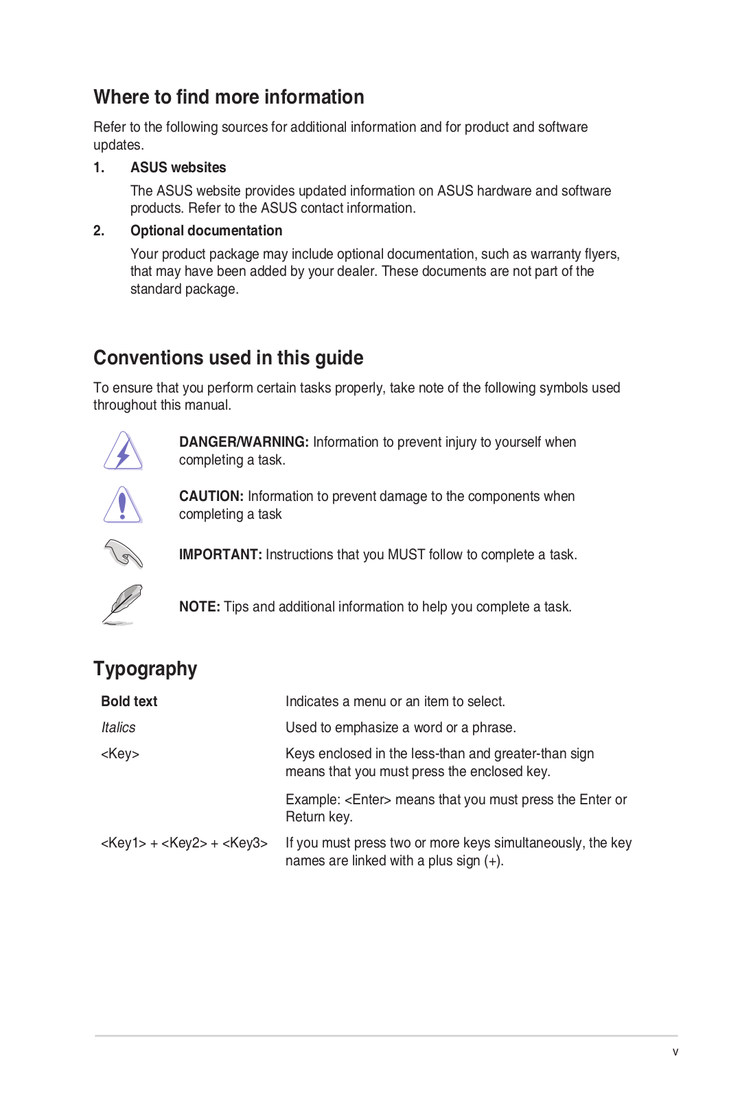
Conventions used in this guide
To ensure that you perform certain tasks properly, take note of the following
symbols used throughout this manual.
DANGER/WARNING: Information to prevent injury to yourself when completing
a task.
CAUTION: Information to prevent damage to the components when completing
a task
IMPORTANT: Instructions that you MUST follow to complete a task.
NOTE: Tips and additional information to help you complete a task.
Typography
- Bold text Indicates a menu or an item to select.
- Italics are Used to emphasize a word or a phrase.
- < Key> Keys enclosed in the less-than and greater-than sign mean that you must press the enclosed key. Example: means that you must press Enter or Return key.
- < Key1> + + If you must press two or more keys simultaneously, the key
names are linked with a plus sign (+).
Package Contents
Check your motherboard package for the following items.
- Motherboard ASUS H110M-R motherboard
- Cables 2 x Serial ATA 6.0 Gb/s cables
- Accessories 1 x I/O Shield
- Application DVD 1 x Support DVD
- Documentation 1 x User Manual
Specifications Summary


Product introduction
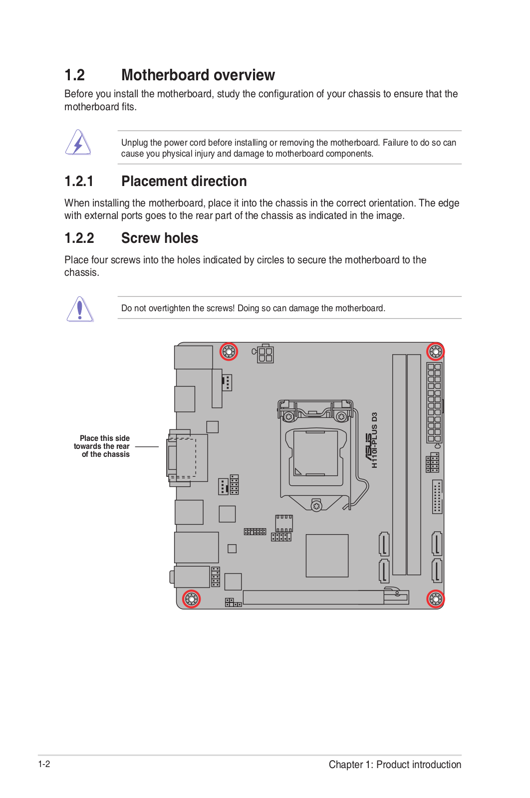
Motherboard overview
- Unplug the power cord from the wall socket before touching any component.
- Before handling components, use a grounded wrist strap or touch a safely grounded object or a metal object, such as the power supply case, to avoid damaging them due to static electricity.
- Before you install or remove any component, ensure that the ATX power supply is switched off or the power cord is detached from the power supply. Failure to do so may cause severe damage to the motherboard, peripherals, or components.
- Unplug the power cord before installing or removing the motherboard. Failure to do so can cause you physical injury and damage to motherboard components


Scan the QR code to get the detailed pin definitions
-
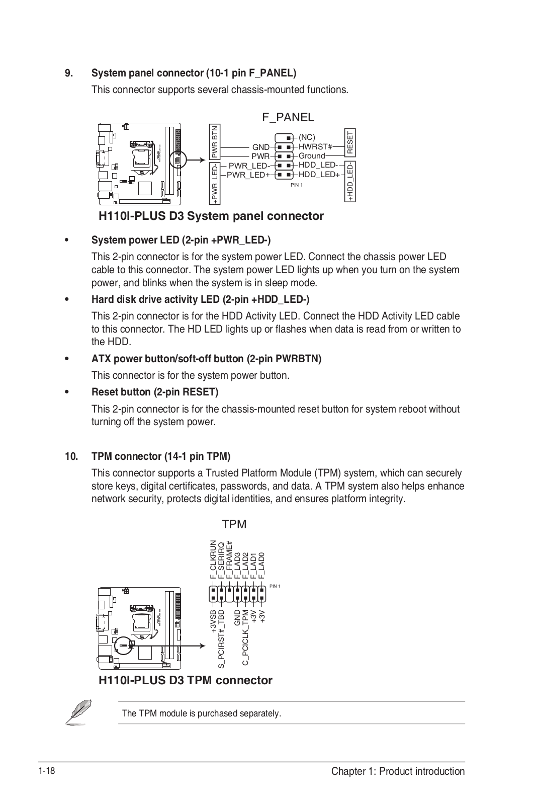
TPM connector (14-1 pin TPM)
This connector supports a Trusted Platform Module (TPM) system, which can
securely store keys, digital certificates, passwords and data. A TPM system
also helps enhance network security, protects digital identities, and ensures
platform integrity. -
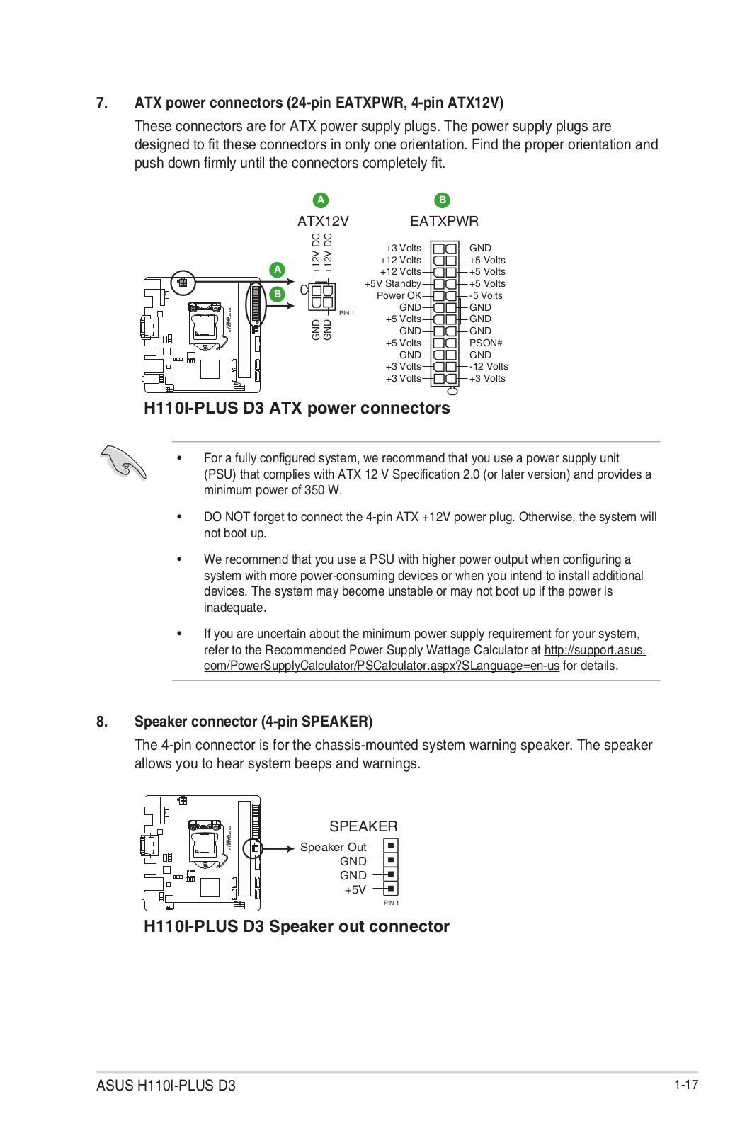
ATX power connectors (24-pin EATXPWR, 4-pin ATX12V)
Correctly orient the ATX power supply plugs into these connectors and push
down firmly until the connectors completely fit.- For a fully configured system, we recommend that you use a power supply unit (PSU) that complies with ATX 12 V Specification 2.0 (or later version) and provides a minimum power of 350 W.
- If you are uncertain about the minimum power supply requirement
for your system, refer to the Recommended Power Supply Wattage Calculator at
http://support.asus.com/PowerSupplyCalculator/PSCalculator.aspx?SLanguage=en-
us for details.
-
Intel® LGA1151 CPU socket
Install Intel® LGA1151 CPU into this surface mount LGA1151 socket, which is
designed for 6th Generation Intel® Core™ i7 / i5 / i3, Pentium®, and Celeron®
processors.
For more details, refer to Central Processing Unit (CPU). -
CPU and chassis fan connectors (4-pin CPU_FAN, 4-pin CHA_FAN)
Connect the fan cables to the fan connectors on the motherboard, ensuring that
the black wire of each cable matches the ground pin of the connector.
Warning Do not forget to connect the fan cables to the fan connectors.
Insufficient air flow inside the system may damage the motherboard components.
These are not jumpers! Do not place jumper caps on the fan connectors! The
CPU_FAN connector supports a CPU fan of a maximum of 1A (12 W) fan power. -
DDR4 DIMM slots
Install 2 GB, 4 GB, 8 GB, and 16 GB unbuffered non-ECC DDR4 DIMMs into these
DIMM sockets. -
Intel® H110 Serial ATA 6.0Gb/s connectors (7-pin SATA6G_1~4)
These connectors connect to Serial ATA 6.0 Gb/s hard disk drives via Serial
ATA 6.0 Gb/s signal cables. -
System panel connector (10-1 pin PANEL)
This connector supports several chassis-mounted functions. -
Chassis intrusion header (4-1 pin CHASSIS)
This header is for a chassis-mounted intrusion detection sensor or switch.
Connect one end of the chassis intrusion sensor or switch cable to this
header. The chassis intrusion sensor or switch sends a high-level signal to
this header when a chassis component is removed or replaced. The signal is
then generated as a chassis intrusion event. By default, the pin labeled
“Chassis Signal” and “Ground” are shorted with a jumper cap. Remove the jumper
caps only when you intend to use the chassis intrusion detection feature. -
Speaker connector (4-pin SPEAKER)
This 4-pin connector is for the chassis-mounted system warning speaker. The
speaker allows you to hear system beeps and warnings. -
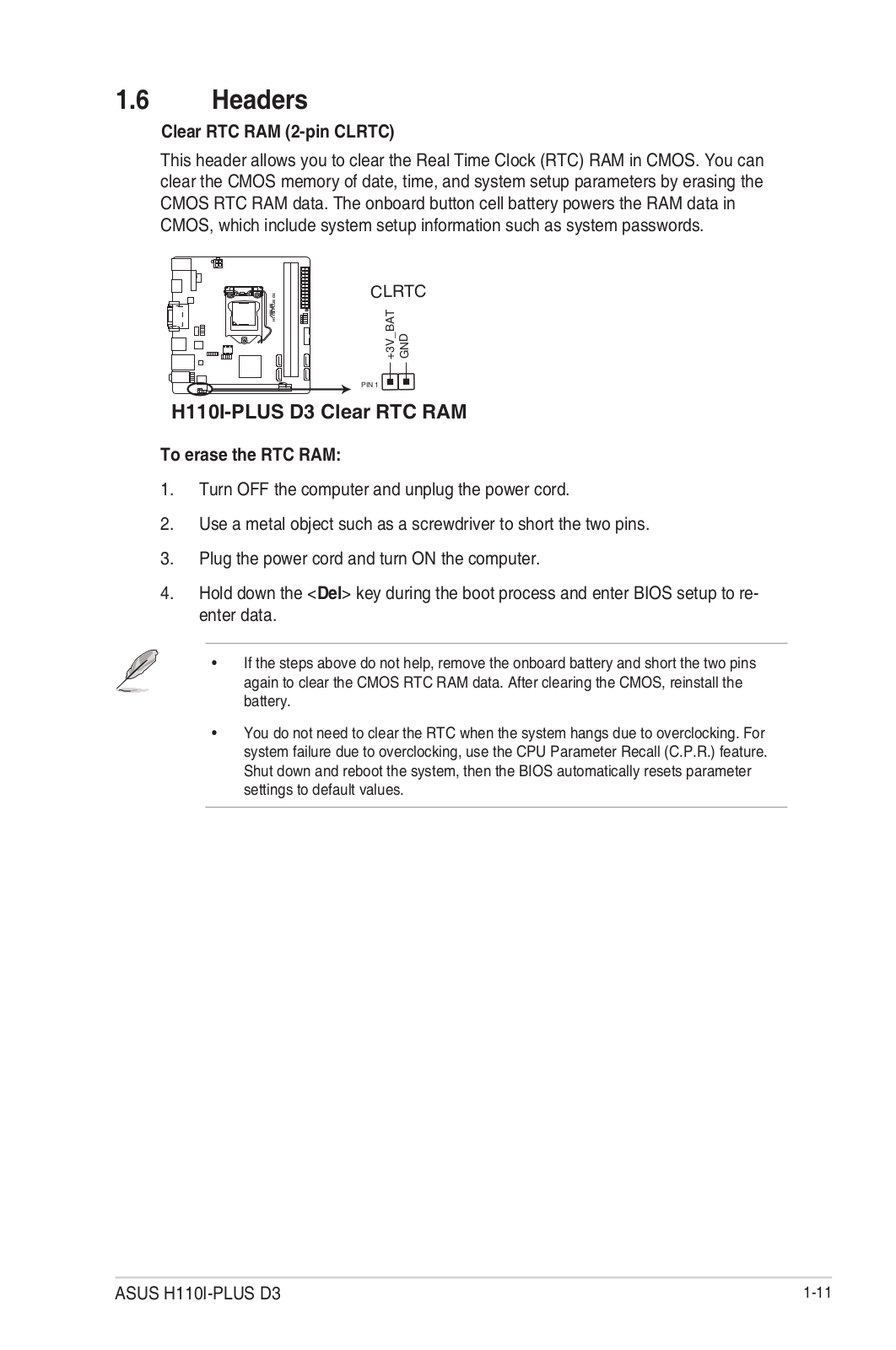
Clear RTC RAM (2-pin CLRTC)
This header allows you to clear the CMOS RTC RAM data of the system setup
information such as date, time, and system passwords.
To erase the RTC RAM: -
Turn OFF the computer and unplug the power cord.
-
Use a metal object such as a screwdriver to short the two pins.
-
Plug the power cord and turn ON the computer.
-
Hold down the key during the boot process and enter BIOS setup to re-enter data.
If the steps above do not help, remove the onboard battery and short the two
pins again to clear the CMOS RTC RAM data. After clearing the CMOS, reinstall
the battery. -
Front panel audio connector (10-1 pin AAFP)
This connector is for a chassis-mounted front panel audio I/O module that
supports either HD Audio or legacy AC`97 audio standard. Connect one end of
the front panel audio I/O module cable to this connector.- We recommend that you connect a high-definition front panel audio module to this connector to avail of the motherboard’s high-definition audio capability.
- If you want to connect a high-definition front panel audio module to this connector, set the Front Panel Type item in the BIOS setup to [HD Audio]. If you want to connect an AC’97 front panel audio module to this connector, set the item to [AC97]. By default, this connector is set to [HD Audio].
-
Serial port connector (10-1 pin COM)
Connect the serial port module cable to this connector, then install the
module to a slot opening at the back of the system chassis. -
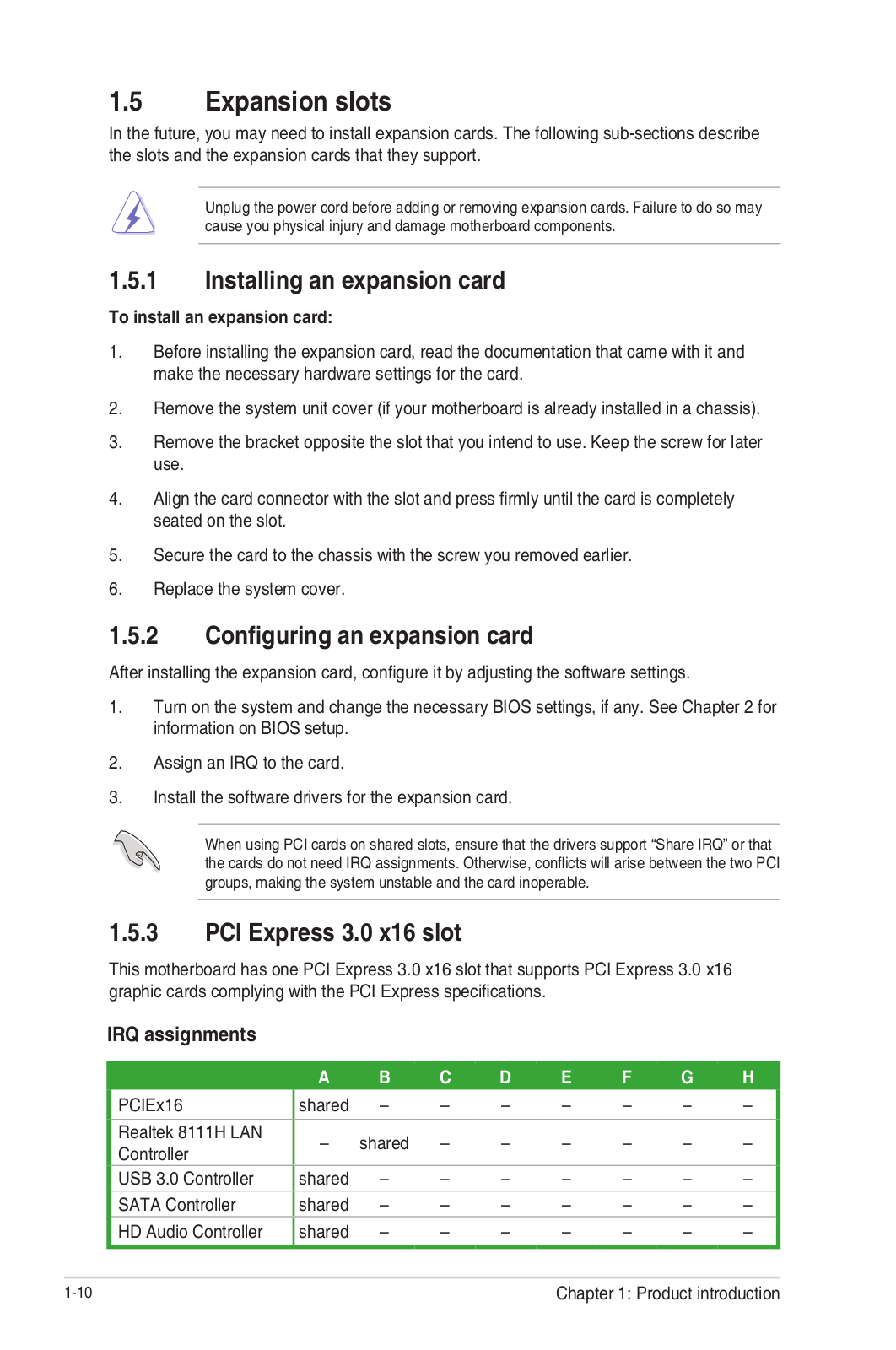
PCI Express 3.0/2.0 x16 slot
This motherboard supports PCI Express 3.0/2.0 x16 graphic cards complying with
the PCI Express specifications. -
PCI Express 2.0 x1 slots
This motherboard has two PCI Express 2.0 x1 slots that support PCI Express x1
network cards, SCSI cards, and other cards that comply with the PCI Express
specifications.
IRQ assignments for this motherboard
When using PCI cards on shared slots, ensure that the drivers
support “Share IRQ” or that the cards do not need IRQ assignments. Otherwise,
conflicts will arise between the two PCI groups, making the system unstable
and the card inoperable. -
LPT connector (26-1 pin LPT)
Connect a parallel port device such as a printer to this LPT (Line Printing
Terminal) connector. -
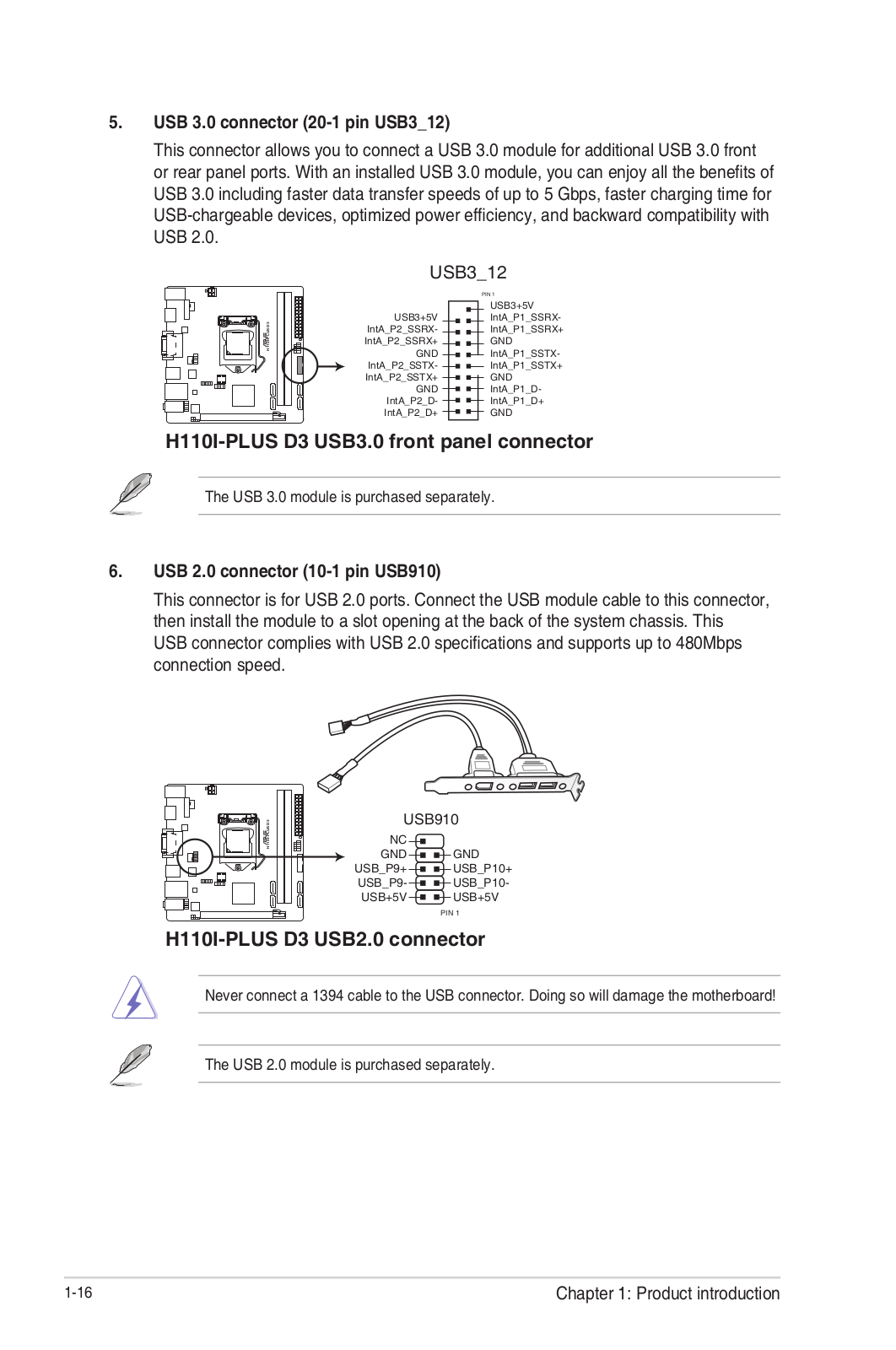
USB 3.0 connector (20-1 pin USB3_12)
Connect a USB 3.0 module to this connector for additional USB 3.0 front or
rear panel ports. This connector complies with USB 3.0 specifications and
provides faster data transfer speeds of up to 5 Gbps, faster charging time for
USB-chargeable devices, optimized power efficiency, and backward compatibility
with USB 2.0 -
USB 2.0 connector (10-1 pin 910)
Connect the USB module cable to this connector, then install the module to a
slot opening at the back of the system chassis. This USB connector complies
with USB 2.0 specifications and supports up to 480Mbps connection speed.

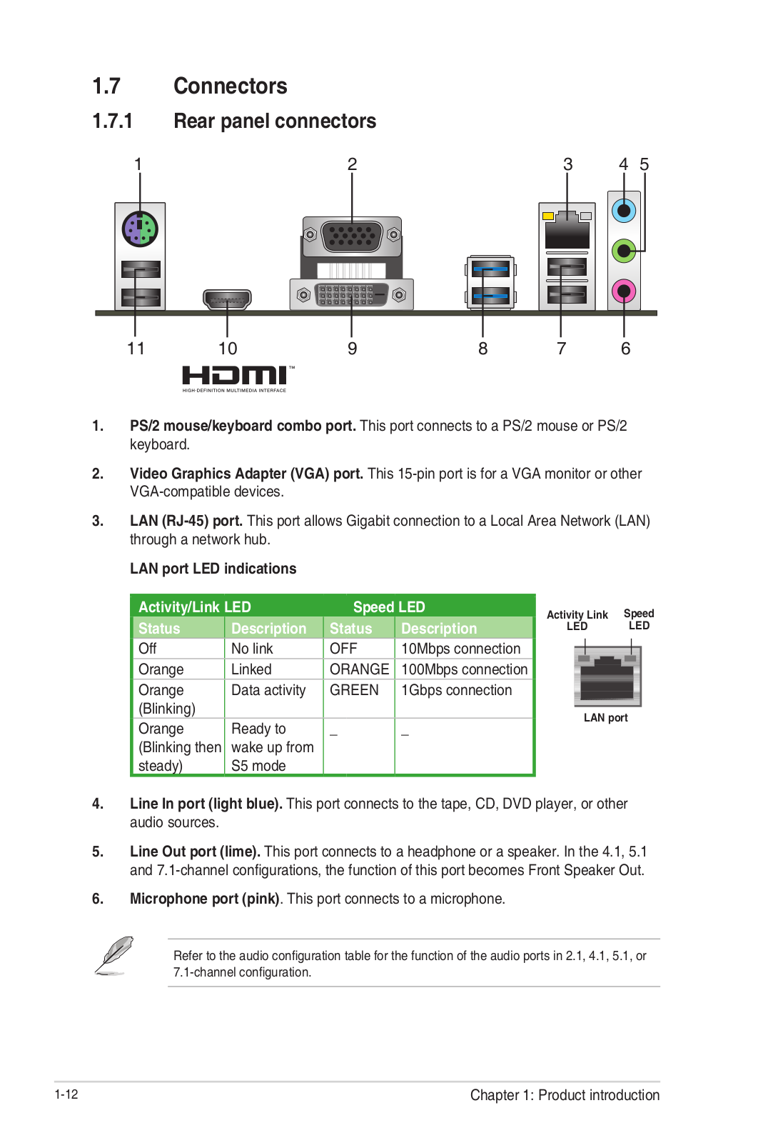
Rear Panel Connectors

- PS/2 mouse port (green). This port is for a PS/2 mouse.
- Video Graphics Adapter (VGA) port. This 15-pin port is for a VGA monitor or other VGA-compatible devices.
- LAN (RJ-45) port. This port allows Gigabit connection to a Local Area Network (LAN) through a network hub.
**LAN port LED indications

**
-
Line In port (light blue). This port connects to the tape, CD, DVD player, or other audio sources.
-
Line Out port (lime). This port connects to a headphone or a speaker. In the 4.1, 5.1 and 7.1-channel configurations, the function of this port becomes Front Speaker Out.
-
Microphone port (pink). This port connects to a microphone.
Refer to the audio configuration table for the function of the audio ports in
2.1, 4.1, 5.1, or 7.1-channel configuration.
Audio 2.1, 4.1, 5.1, or 7.1-channel configuration
To configure a 7.1-channel audio output:
Use a chassis with HD audio module in the front panel to support a
7.1-channel audio output.
-
USB 2.0 ports. These 4-pin Universal Serial Bus (USB) ports are for USB 2.0/1.1 devices.
-
USB 3.0 ports. These 9-pin Universal Serial Bus (USB) ports are for USB 3.0/2.0 devices.
- USB 3.0 devices can only be used for data storage.
- We strongly recommend that you connect USB 3.0 devices to USB 3.0 ports for faster and better performance from your USB 3.0 devices.
- Due to the design of the Intel® 100 series chipset, all USB devices connected to the USB 2.0 and USB 3.0 ports are controlled by the xHCI controller. Some legacy USB devices must update their firmware for better compatibility.
-
HDMI port. This port is for a High-Definition Multimedia Interface (HDMI) connector and is HDCP compliant allowing playback of HD DVD, Blu-Ray, and other protected content.
-
DVI-D port. This port is for any DVI-D compatible device.
DVI-D can not be converted to output from RGB Signal to CRT and is not
compatible with DVI-I. -
PS/2 keyboard port (purple). This port is for a PS/2 keyboard.

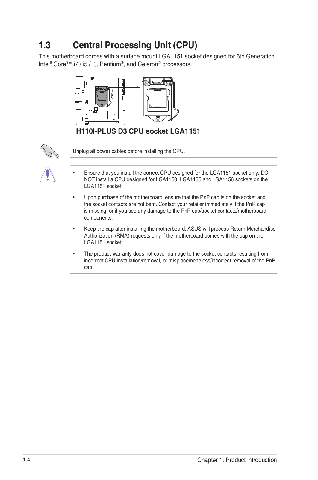
Central Processing Unit (CPU)
This motherboard comes with a surface mount LGA1151 socket designed for 6th
Generation Intel® Core™ i7 / i5 / i3, Pentium®, and Celeron® processors.
Unplug all power cables before installing the CPU.
-
Ensure that you install the correct CPU designed for the LGA1151 socket only. DO NOT install a CPU designed for LGA1150, LGA1155 and LGA1156 sockets on the LGA1151 socket.
-
Upon purchase of the motherboard, ensure that the PnP cap is on the socket and the socket contacts are not bent. Contact your retailer immediately if the PnP cap
is missing, or if you see any damage to the PnP cap/socket
contacts/motherboard components. -
Keep the cap after installing the motherboard. ASUS will process Return Merchandise Authorization (RMA) requests only if the motherboard comes with the cap on the LGA1151 socket.
-
The product warranty does not cover damage to the socket contacts resulting from incorrect CPU installation/removal, or misplacement/loss/incorrect removal of the PnP cap.
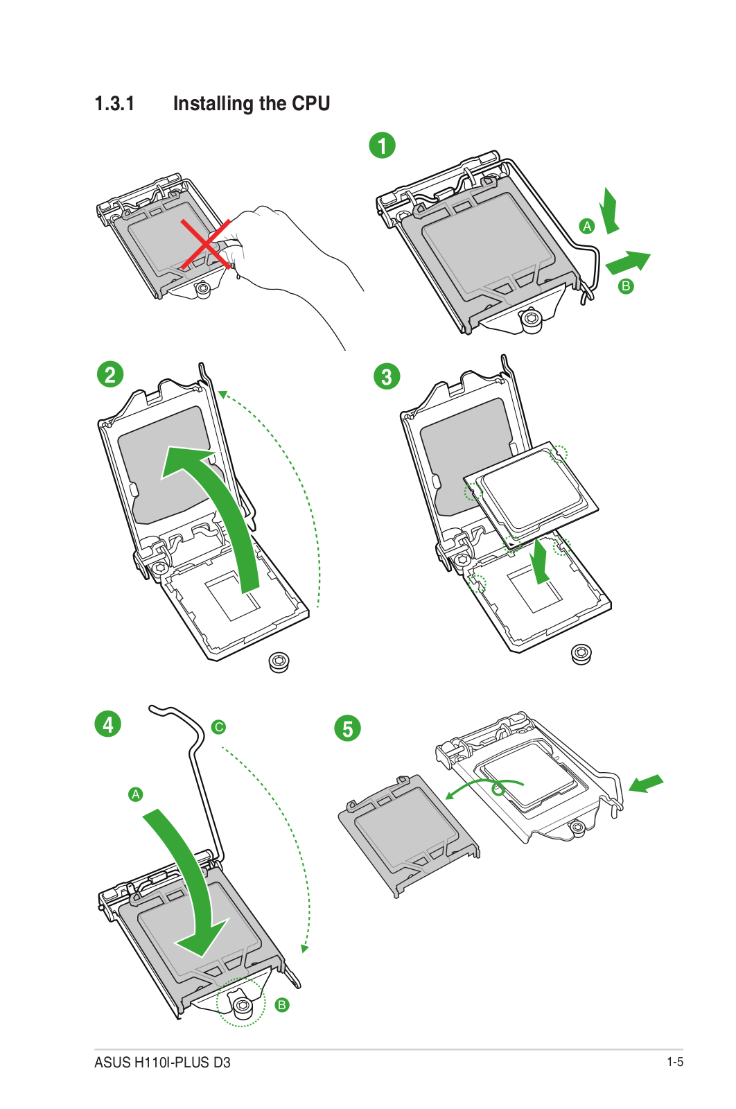
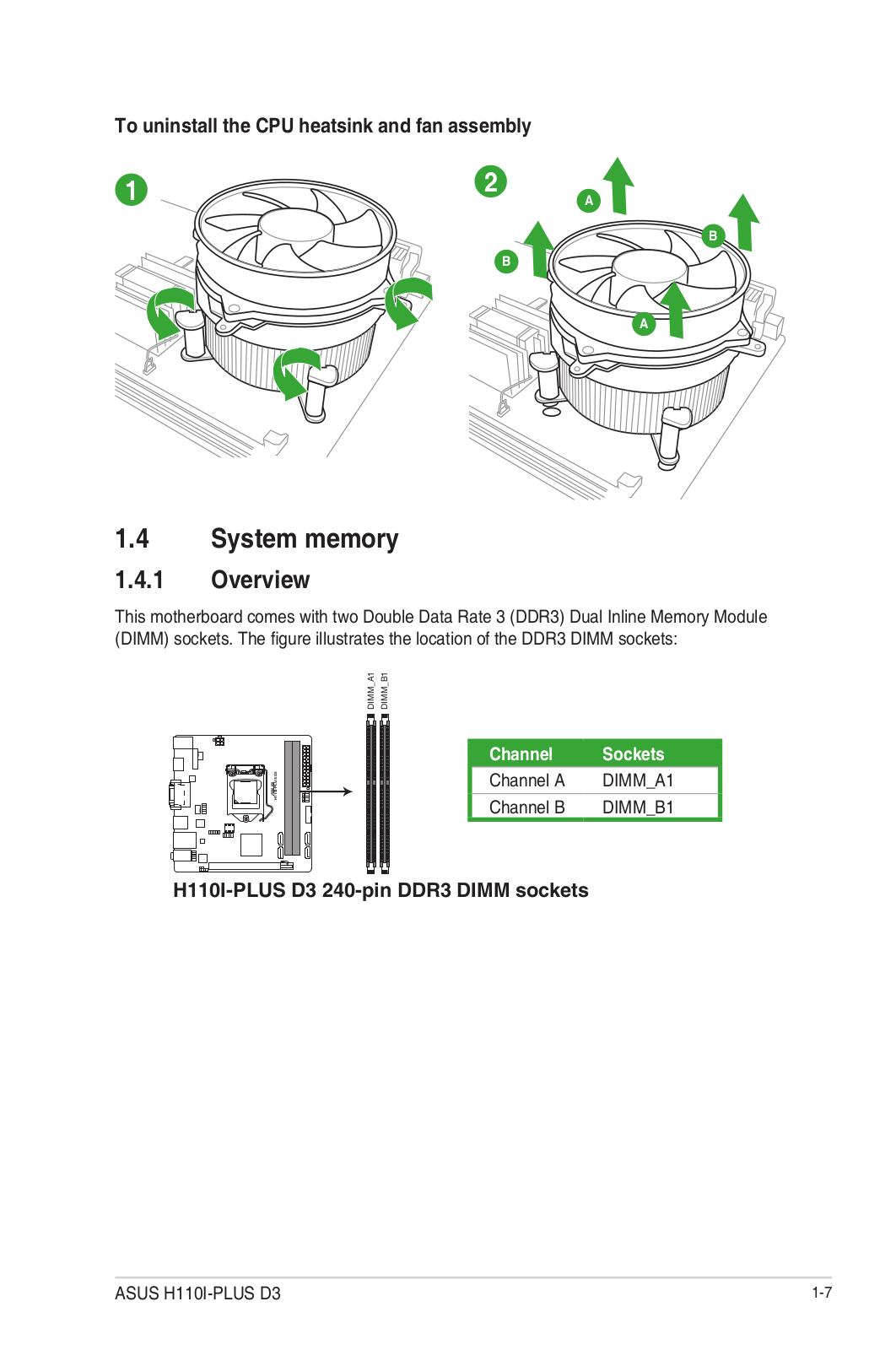
Installing the CPU

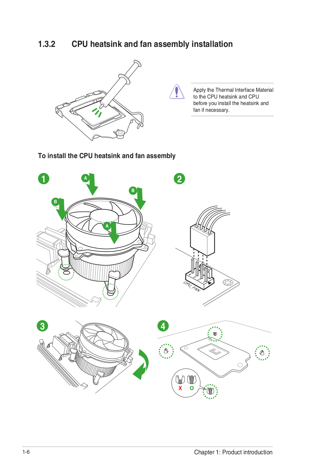
Warning Apply the Thermal Interface Material to the CPU heatsink and CPU
before you install the heatsink and fan if necessary.
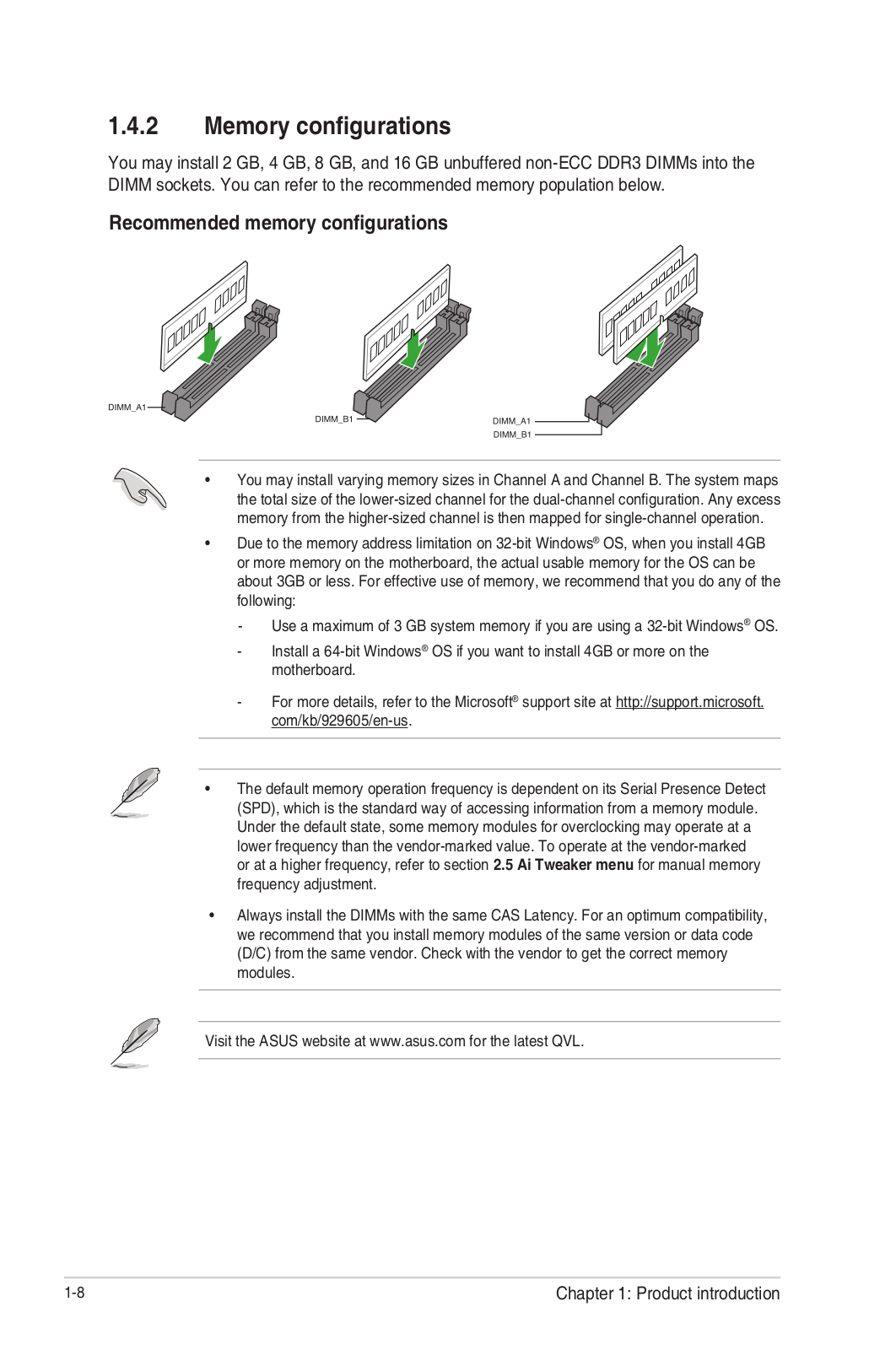
System Memory
Overview
This motherboard comes with two Double Data Rate 4 (DDR4) Dual Inline Memory
Module (DIMM) sockets. The figure illustrates the location of the DDR4 DIMM
sockets:

-
You may install varying memory sizes in Channel A and Channel B. The system maps the total size of the lower-sized channel for the dual-channel configuration. Any excess memory from the higher-sized channel is then mapped for single-channel operation.
-
Always install the DIMMS with the same CAS Latency. For optimum compatibility, we recommend that you install memory modules of the same version or data code
(D/C) from the same vendor. Check with the vendor to get the correct memory
modules. -
According to Intel® CPU spec, DIMM voltage below 1.35V is recommended to protect the CPU.
-
Due to the memory address limitation on 32-bit Windows® OS, when you install 4GB or more memory on the motherboard, the actual usable memory for the OS can be about 3GB or less. For effective use of memory, we recommend that you do any of the following:
- Use a maximum of 3 GB system memory if you are using a 32-bit Windows® OS.
- Install a 64-bit Windows® OS if you want to install 4GB or more on the motherboard.
- For more details, refer to the Microsoft® support site at http://support.microsoft.com/kb/929605/en-us.
Visit the ASUS website at www.asus.com for the latest
QVL.
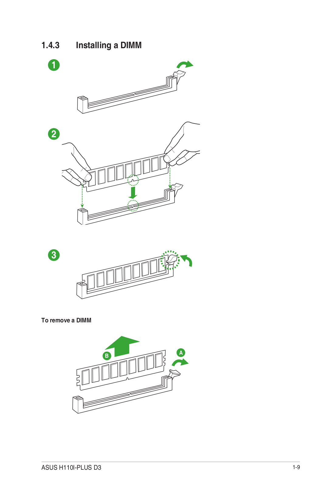
Installing a DIMM

To remove a DIMM
Intel® SBB support
Intel® SBB (Small Business Basics) is an entry software solution that provides
simple, out-of-the-box value for small businesses.
Intel® SBB requires MEI driver (AMT host software kit) to be installed and
running.
Platform requirements:
- Windows® 7 (32/64-bit) / Windows® 8.1 (64-bit) / Windows® 10 (64-bit)
- PCH with 6th-generation Intel® Core™ CPU (100 Series platforms) with 2MB Intel® Management Engine 11.0 firmware installed
CPU and chipsets requirements:
- Intel® Core™ i3 / i5 /i7 with one of these chipsets: H110, B150, H170, Q170
Other requirements:
- Local Administrator rights on the target machine
- Visit the ASUS website at www.asus.com for the latest CPU QVL (Qualified Vendors List).
- Uninstall SBA4.0 before you install and upgrade to the latest version.
BIOS information
- Scan the QR code to view the BIOS update guide.
- Before using the ASUS CrashFree BIOS 3 utility, rename the BIOS file in the removable device into H110MR.CAP.
BIOS setup program
Use the BIOS Setup program to update the BIOS or configure its parameters. The
BIOS screens include navigation keys and brief online help to guide you in
using the BIOS Setup program.
Entering BIOS Setup at startup
To enter BIOS Setup at startup:
Press or during the Power-On Self Test (POST). If you do not
press or , POST continues with its routines.
Entering BIOS Setup after POST
To enter BIOS Setup after POST:
- Press ++ simultaneously.
- Press the reset button on the system chassis.
- Press the power button to turn the system off then back on. Do this option only if you failed to enter BIOS Setup using the first two options.
Warning Using the power button, reset button, or the ++
keys to force reset from a running operating system can cause damage to your
data or system. We recommend you always shut down the system properly from the
operating system.
- The BIOS setup screens shown in this section are for reference purposes only, and may not exactly match what you see on your screen.
- Visit the ASUS website at www.asus.com to download the latest BIOS file for this motherboard.
- If the system becomes unstable after changing any BIOS setting, load the default settings to ensure system compatibility and stability. Select the Load Optimized Defaults item under the Exit menu or press hotkey F5.
- If the system fails to boot after changing any BIOS setting, try to clear the CMOS and reset the motherboard to the default value. See the section Motherboard Overview for information on how to erase the RTC RAM.
BIOS menu screen
The BIOS setup program can be used under two modes: EZ Mode and Advanced Mode.
Press to change between the two modes.
EZ Mode
By default, the EZ Mode screen appears when you enter the BIOS setup program.
The EZ Mode provides you an overview of the basic system information and
allows you to select the display language, system performance mode, fan
profile and boot device priority. To access the Advanced Mode, click Advanced
Mode(F7) or press .
The default screen for entering the BIOS setup program can be changed. Refer
to the Setup Mode item in section 2.8 Boot menu for details.

The boot device options vary depending on the devices you installed to the
system.
Advanced Mode
The Advanced Mode provides advanced options for experienced end-users to
configure the BIOS settings. The figure below shows an example of the Advanced
Mode. Refer to the following sections for the detailed configurations.
To access the EZ Mode, click EzMode(F7) or press .

Search on FAQ
Move your mouse over this button to show a QR code. Scan this QR code with
your mobile device to connect to the ASUS BIOS FAQ web page. You can also scan
the QR code below.
The Exit menu items allow you to load the optimal default values for the BIOS
items, and save or discard your changes to the BIOS items.

-
Load Optimized Defaults
This option allows you to load the default values for each of the parameters
on the Setup menus. When you select this option or if you press , a
confirmation window appears. Select OK to load the default values. -
Save Changes & Reset
Once you are finished making your selections, choose this option from the Exit
menu to ensure the values you selected are saved. When you select this option
or if you press , a confirmation window appears. Select OK to save
changes and exit. -
Discard Changes and Exit
This option allows you to exit the Setup program without saving your changes.
When you select this option or if you press , a confirmation window
appears. Select OK to discard changes and exit. -
Launch EFI Shell from USB drives
This option allows you to attempt to launch the EFI Shell application
(shellx64.efi) from one of the available USB devices.
Appendices
Notices
Federal Communications Commission Statement
This device complies with Part 15 of the FCC Rules. Operation is subject to
the following two conditions:
- This device may not cause harmful interference.
- This device must accept any interference received including interference that may cause undesired operation.
This equipment has been tested and found to comply with the limits for a Class
B digital device, pursuant to Part 15 of the FCC Rules. These limits are
designed to provide reasonable protection against harmful interference in a
residential installation. This equipment generates, uses, and can radiate
radio frequency energy and, if not installed and used in accordance with the
manufacturer’s instructions, may cause harmful interference to radio
communications. However, there is no guarantee that interference will not
occur in a particular installation. If this equipment does cause harmful
interference to radio or television reception, which can be determined by
turning the equipment off and on, the user is encouraged to try to correct the
interference by one or more of the following measures:
- Reorient or relocate the receiving antenna.
- Increase the separation between the equipment and the receiver.
- Connect the equipment to an outlet on a circuit different from that to which the receiver is connected.
- Consult the dealer or an experienced radio/TV technician for help.
Danger: The use of shielded cables for the connection of the monitor to
the graphics card is required to assure compliance with FCC regulations.
Changes or modifications to this unit not expressly approved by the party
responsible for compliance could void the user’s authority to operate this
equipment.
IC: Canadian Compliance Statement
Complies with the Canadian ICES-003 Class B specifications. This device
complies with RSS 210 of Industry Canada. This Class B device meets all the
requirements of Canadian interference-causing equipment regulations. This
device complies with Industry Canada license-exempt RSS standard(s). Operation
is subject to the following two conditions:
- This device may not cause interference, and
- This device must accept any interference, including interference that may cause undesired operation of the device.
Canadian Department of Communications Statement
This digital apparatus does not exceed the Class B limits for radio noise
emissions from digital apparatus set out in the Radio Interference Regulations
of the Canadian
Department of Communications.
This class B digital apparatus complies with Canadian ICES-003.
VCCI: Japan Compliance Statement VCCI Class B Statement
This is a Class B product based on the standard of the VCCI Council. If this
is used near a radio or television receiver in a domestic environment, it may
cause radio interference. Install and use the equipment according to the
instruction manual.
This is a Class B product based on the standard of the VCCI Council. If this
is used near a radio or television receiver in a domestic environment, it may
cause radio interference. Install and use the equipment according to the
instruction manual.
KC: Korea Warning Statement
REACH
Complying with the REACH (Registration, Evaluation, Authorisation, and
Restriction of Chemicals) regulatory framework, we published the chemical
substances in our products at ASUS REACH website at
http://csr.asus.com/english/REACH.htm.
Disposal
- DO NOT throw the motherboard in municipal waste. This product has been designed to enable proper reuse of parts and recycling. This symbol of the crossed-out wheeled bin indicates that the product (electrical and electronic equipment) should not be placed in municipal waste. Check local regulations for the disposal of electronic products.
- DO NOT throw the mercury-containing button cell battery in municipal waste. This symbol of the crossed-out wheeled bin indicates that the battery should not be placed in municipal waste.
ASUS Recycling/Takeback Services
ASUS recycling and takeback programs come from our commitment to the highest
standards for protecting our environment. We believe in providing solutions
for you to be able to responsibly recycle our products, batteries, other
components as well as packaging materials. Please go to
http://csr.asus.com/english/Takeback.htm for detailed recycling information
in different regions.
Google™ License Terms
Copyright© 2014 Google Inc. All Rights Reserved.
Licensed under the Apache License, Version 2.0 (the “License”); you may not
use this file except in compliance with the License. You may obtain a copy of
the License at:
http://www.apache.org/licenses/LICENSE-2.0 Unless required by applicable law
or agreed to in writing, software distributed under the License is distributed
on an “AS IS” BASIS, WITHOUT WARRANTIES OR CONDITIONS OF ANY KIND, either
express or implied. See the License for the specific language governing
permissions and limitations under the License.
AsusTek Inc. hereby declares that this device is in compliance with the
essential requirements and other relevant provisions of CE Directives. Please
see the CE Declaration of Conformity for more details.
ASUS contact information ASUSTeK COMPUTER INC.
- Address 4F, No. 150, Li-Te Rd., Peitou, Taipei 112, Taiwan
- Telephone +886-2-2894-3447
- Fax +886-2-2890-7798
- Web site www.asus.com/
FAQ’s
What is the size of the ASUS H110M-R motherboard?
The ASUS H110M-R is a micro ATX motherboard, which measures 9.0 x 7.2 inches.
What processors are compatible with the ASUS H110M-R motherboard?
The ASUS H110M-R is compatible with 6th and 7th generation Intel Core
i7/i5/i3, Pentium, and Celeron processors.
How many RAM slots does the ASUS H110M-R motherboard have?
The ASUS H110M-R has two DDR4 DIMM slots, which support up to 32GB of system
memory.
What is the maximum RAM speed supported by the ASUS H110M-R motherboard?
The ASUS H110M-R supports DDR4 memory speeds up to 2133MHz.
How many PCIe slots does the ASUS H110M-R motherboard have?
The ASUS H110M-R has one PCIe 3.0 x16 slot and two PCIe 2.0 x1 slots.
What storage devices are supported by the ASUS H110M-R motherboard?
The ASUS H110M-R supports SATA III 6Gb/s storage devices.
What networking options are available on the ASUS H110M-R motherboard?
The ASUS H110M-R has Gigabit Ethernet LAN and Realtek RTL8111H network
controller.
What audio options are available on the ASUS H110M-R motherboard?
The ASUS H110M-R has Realtek ALC887 7.1 Surround Sound High Definition Audio
CODEC.
What type of USB ports are available on the ASUS H110M-R motherboard?
The ASUS H110M-R has six USB 2.0 ports and four USB 3.0 ports.
Does the ASUS H110M-R motherboard support Intel Optane Memory technology?
No, the ASUS H110M-R motherboard does not support Intel Optane Memory
technology.
Download The PDF Link:ASUS H110M-R Micro ATX DDR4 HDMI Motherboard User
Manual
Read User Manual Online (PDF format)
Read User Manual Online (PDF format) >>
Download This Manual (PDF format)
Download this manual >>
На чтение10 мин
Опубликовано
Обновлено
При сборке компьютера важно правильно подключить переднюю панель к материнской плате. В данной статье мы рассмотрим процесс подключения передней панели к материнской плате ASUS H110M R и дадим подробную инструкцию, которая поможет вам выполнить эту задачу с минимальными усилиями.
Передняя панель компьютера включает в себя различные разъемы и кнопки, которые предоставляют удобный доступ к различным функциям. При правильном соединении передней панели с материнской платой вы сможете использовать эти функции без проблем.
Процесс подключения передней панели к материнской плате ASUS H110M R состоит из нескольких шагов. Сначала вам потребуется найти переднюю панель в корпусе компьютера. Обычно она расположена внизу передней панели и прикреплена к корпусу с помощью кабеля.
Содержание
- Подключение передней панели к материнской плате
- Описание материнской платы ASUS H110M R
- Инструкция по подключению передней панели
- Необходимые инструменты и материалы
- Этапы подключения передней панели
- Открытие корпуса компьютера
- Определение разъемов на материнской плате
- Подключение разъемов с передней панели к материнской плате
Подключение передней панели к материнской плате
Для подключения передней панели необходимо сначала найти внутренний разъем на материнской плате. Обычно этот разъем располагается в нижней части платы и обозначен специальной надписью «Front Panel» или «PW».
После того, как вы нашли разъем, необходимо подключить провода от передней панели к соответствующим контактам на разъеме. Обычно на передней панели присутствуют следующие порты и кнопки:
- Power SW — кнопка включения/выключения компьютера
- Reset SW — кнопка сброса
- Power LED — индикатор питания
- HDD LED — индикатор активности жесткого диска
- Audio — разъемы для аудио-устройств
- USB — разъемы для подключения USB-устройств
Внимательно прочитайте инструкции, прилагающиеся к вашей материнской плате, чтобы узнать, какие контакты на разъеме соответствуют каждой кнопке или порту на передней панели.
Обычно провода от передней панели имеют разные цвета, что помогает идентифицировать их. Например, провода от кнопок могут быть разного цвета, а провода от индикаторов — другого цвета.
Подключение передней панели к материнской плате требует аккуратности. Убедитесь, что провода плотно прикреплены к контактам и не перекрывают друг друга. Это поможет избежать возможных проблем с работой компьютера.
После того, как все провода подключены правильно, закройте корпус компьютера и подключите его к источнику питания. Затем включите компьютер и проверьте работу передней панели, нажимая на кнопки и проверяя работу индикаторов.
Теперь вы знаете, как подключить переднюю панель к материнской плате и можете наслаждаться удобством использования всех портов и кнопок на вашем компьютере.
Описание материнской платы ASUS H110M R
Плата имеет форм-фактор Micro ATX, что обеспечивает удобство при установке в корпус. Она оснащена сокетом LGA 1151, который поддерживает процессоры с разъемами LGA 1151.
Кроме того, ASUS H110M R обладает широкими возможностями для расширения: на плате предусмотрены разъемы PCI Express x16 и x1, а также слоты для подключения оперативной памяти типа DDR4. Максимальный объем оперативной памяти составляет 32 ГБ.
Материнская плата поддерживает быструю передачу данных благодаря наличию разъемов USB 3.0. Кроме того, на плате расположены разъемы SATA, что позволяет подключить к ней несколько устройств хранения данных.
ASUS H110M R обладает высоким качеством звука благодаря встроенному аудиокодеку, который обеспечивает многоканальное воспроизведение.
Материнская плата ASUS H110M R отличается надежностью и безопасностью. Она оснащена защитой от перенапряжения и имеет качественные компоненты, которые гарантируют длительное и стабильное функционирование системы.
Инструкция по подключению передней панели
Переднюю панель компьютера можно подключить к материнской плате ASUS H110M R, следуя следующим шагам:
- Откройте корпус компьютера, снимите заднюю крышку и обнаружьте переднюю панель.
- Соскребите остатки термопасты с процессора и радиатора с помощью нитроциллиозного растворителя.
- На передней панели обнаружьте разъемы для подключения к материнской плате. Обычно это разъемы Power SW, Reset SW, HDD LED и Power LED.
- Сравните разъемы на передней панели с разъемами на материнской плате. Убедитесь, что они совпадают по типу и конфигурации.
- Подключите провода от передней панели к соответствующим разъемам на материнской плате. Обратите внимание на правильную полярность подключения проводов.
- Проверьте правильность подключения передней панели, убедившись, что провода надежно закреплены в разъемах и не перекручены.
- Закройте корпус компьютера и зафиксируйте заднюю крышку.
- Подключите компьютер к розетке и включите его. Проверьте работу передней панели, убедившись, что кнопки Power и Reset работают, индикаторы HDD и Power светятся.
Теперь вы успешно подключили переднюю панель к материнской плате ASUS H110M R и можете пользоваться всеми ее функциями.
Необходимые инструменты и материалы
Для подключения передней панели к материнской плате ASUS H110M R вам понадобятся следующие инструменты и материалы:
1. Крестовая отвертка: Вам понадобится крестовая отвертка для откручивания и закручивания винтов.
2. Передняя панель компьютера: Убедитесь, что у вас есть передняя панель компьютера, которую вы хотите подключить.
3. Кабель передней панели (оргкабель): Обычно этот кабель имеет разъемы для подключения различных кнопок и индикаторов передней панели к материнской плате.
4. Руководство пользователя: Приготовьте руководство пользователя материнской платы ASUS H110M R, чтобы иметь подробные инструкции о том, как правильно подключить переднюю панель.
Убедитесь, что у вас есть все необходимые инструменты и материалы перед тем, как приступать к подключению передней панели к материнской плате ASUS H110M R.
Этапы подключения передней панели
- Перед началом подключения передней панели убедитесь, что компьютер выключен и питание отключено. Это необходимо для предотвращения возможности повреждения компонентов материнской платы или корпуса.
- Найдите переднюю панель корпуса компьютера. Обычно передняя панель находится в нижней части передней панели корпуса и содержит различные разъемы и кнопки.
- Найдите соответствующие разъемы на материнской плате для подключения передней панели. Обычно эти разъемы располагаются в нижней части материнской платы и помечены соответствующими обозначениями.
- Посмотрите на провода, идущие от передней панели, и найдите соответствующие маркировки на разъемах материнской платы. Обычно различные провода имеют различные цвета или имеют маркировки (+/-), что помогает определить их местоположение.
- Соотнесите провода от передней панели с разъемами на материнской плате и аккуратно вставьте их в соответствующие разъемы. Убедитесь, что провода вставлены прочно и надежно.
- После подключения всех проводов передней панели, закрепите их с помощью силовых зажимов или зажимов проводов. Это поможет избежать возможности отключения проводов во время работы компьютера.
- Теперь у вас должно быть завершено подключение передней панели к материнской плате. Убедитесь, что все провода находятся в правильном положении и надежно закреплены.
- После завершения подключения передней панели можно подключить питание к компьютеру и включить его. Проверьте корректность работы кнопок и разъемов передней панели.
Обратите внимание, что процесс подключения передней панели может немного отличаться в зависимости от модели материнской платы. Всегда проверяйте инструкции производителя или руководство пользователя для вашей конкретной материнской платы, чтобы получить точные указания по подключению передней панели.
Открытие корпуса компьютера
Для подключения передней панели материнской платы ASUS H110M R необходимо сначала открыть корпус компьютера. Во избежание повреждений компонентов и электростатического разряда, рекомендуется предварительно отключить питание и снять статическое электричество, прикоснувшись к заземленному объекту.
На корпусе компьютера обычно есть специальные винты или защелки, которые необходимо удалить или открыть с помощью отвертки или пальцев. В зависимости от модели корпуса, может понадобиться снять боковую панель или верхнюю крышку.
После того как корпус открыт, можно увидеть внутренние компоненты компьютера, включая материнскую плату. Переднюю панель можно обнаружить внутри корпуса, обычно она располагается в верхней части или рядом с передней панелью.
После обнаружения передней панели на материнской плате, необходимо внимательно рассмотреть разъемы и контакты. Обычно передняя панель подключается с помощью специального разъема, который будет помечен в руководстве или на самой плате. Обратите внимание на расположение пинов и ориентацию разъема, чтобы правильно подключить переднюю панель.
После подключения передней панели к материнской плате, закройте корпус компьютера, зафиксировав его винтами или защелками. Убедитесь, что все винты плотно закреплены, чтобы избежать нежелательных движений и шума во время работы компьютера.
Теперь, когда корпус закрыт, вы можете включить компьютер и проверить работу передней панели. Убедитесь, что все кнопки и порты функционируют должным образом. Если что-то не работает, проверьте подключение передней панели или обратитесь к руководству пользователя материнской платы.
Определение разъемов на материнской плате
Перед тем как приступить к подключению передней панели к материнской плате ASUS H110M R, необходимо уметь определить разъемы на самой плате. Важно понимать их назначение и расположение, чтобы правильно подключить все необходимые провода.
На материнской плате обычно находится несколько разъемов, предназначенных для подключения передней панели корпуса. Некоторые из них могут быть обозначены буквами и символами, а другие — цветами. Разъемы на плате обычно расположены вблизи задней панели, где находятся порты для подключения устройств.
Основные разъемы, которые могут быть на материнской плате, включают:
- USB-разъемы: они могут быть обозначены буквами «USB» или символом «U». Они предназначены для подключения USB-портов на передней панели корпуса. Разъемы USB обычно имеют 9 контактов.
- Аудио-разъемы: они могут быть обозначены буквами «A» или символом «А». Они предназначены для подключения аудио-портов на передней панели корпуса. Обычно на материнской плате может быть несколько аудио-разъемов с разными цветами, обозначающими назначение портов (например, розовый — микрофон, зеленый — наушники).
- Разъемы для светодиодов и кнопок: они могут быть обозначены буквами «HDDLED», «PWRLED», «RESET», «PWR» и т.д. Они предназначены для подключения светодиодов и кнопок с передней панели корпуса, таких как индикатор активности жесткого диска, кнопка сброса и кнопка включения питания.
- Разъемы для вентиляторов: они могут быть обозначены буквами «FAN» или символом «FAN». Они предназначены для подключения вентиляторов системы, которые помогают охлаждать компоненты платы и корпуса.
- Разъемы SATA: они могут быть обозначены буквами «SATA» или символом «SATA». Они предназначены для подключения устройств хранения данных, таких как жесткие диски и оптические приводы.
- Разъемы питания: они могут быть обозначены буквами «ATX_PWR» или символом «PWR». Они предназначены для подключения кабелей питания от блока питания компьютера.
Если вы знаете расположение и назначение разъемов на материнской плате, вы сможете легко подключить переднюю панель корпуса и настроить все соединения согласно потребностям вашего компьютера.
Подключение разъемов с передней панели к материнской плате
Передняя панель компьютерного корпуса обычно имеет несколько разъемов, которые позволяют подключить различные устройства, такие как кнопка питания, светодиодные индикаторы, аудио разъемы и USB порты, к материнской плате. Процесс подключения разъемов достаточно прост и может быть выполнен любым пользователем.
Перед началом подключения следует убедиться, что компьютер выключен и обесточен. Далее, следует найти на материнской плате разъемы для передней панели. Обычно они располагаются в нижней части платы.
Изначально, вам будет необходимо подключить панель кнопки питания. Для этого, вам понадобится найти на материнской плате разъем с надписью «Power SW» или «PWR BTN». После нахождения, вам нужно будет подключить онго провода от передней панели компьютера к соответствующим контактам. Обычно для этого используется двухпиновый разъем.
Далее, следует подключить разъемы светодиодных индикаторов, если они есть на панели передней панели корпуса. Обычно для этого на материнской плате предусмотрены разъемы с надписями «HDD LED» или «Power LED». Во избежание ошибок, следует обратиться к документации вашей материнской платы для получения исчерпывающей информации о разъемах.
Кроме того, передняя панель может иметь аудио разъемы для подключения наушников или микрофона. Для этого, на материнской плате должен быть разъем с надписью «HD Audio» или «AC97 Audio». Также, следует обратиться к документации материнской платы, чтобы подключить разъемы правильно.
Наконец, передняя панель может иметь USB порты. Для подключения USB портов к материнской плате, необходимо найти соответствующие разъемы, которые могут иметь надпись «USB» или «FP_USB». Обычно их на материнской плате несколько. Подключите провода от передней панели к контактам материнской платы.
Как только все разъемы будут подключены, Вы можете закрыть корпус компьютера и завершить процесс сборки. После этого, можно включать компьютер и проверить работоспособность всех подключенных устройств на передней панели.
| Разъем | Контакты | Подключение |
|---|---|---|
| Кнопка питания | 2-пиновый разъем | Подключить провода к разъему «Power SW» или «PWR BTN» |
| Светодиодные индикаторы | 2-пиновый разъем | Подключить провода к разъему «HDD LED» или «Power LED» |
| Аудио разъемы | 2-пиновый или 9-пиновый разъем | Подключить провода к разъему «HD Audio» или «AC97 Audio» |
| USB порты | 4-пиновый разъем | Подключить провода к разъему «USB» или «FP_USB» |