

Motherboard
PRIME
X299-A II

ii
E15936
Revised Edition V2
October 2019
Copyright© 2019 ASUSTeK COMPUTER INC. All Rights Reserved.
No part of this manual, including the products and software described in it, may be reproduced,
transmitted, transcribed, stored in a retrieval system, or translated into any language in any form or by any
means, except documentation kept by the purchaser for backup purposes, without the express written
permission of ASUSTeK COMPUTER INC. (“ASUS”).
Product warranty or service will not be extended if: (1) the product is repaired, modied or altered, unless
such repair, modication of alteration is authorized in writing by ASUS; or (2) the serial number of the
product is defaced or missing.
ASUS PROVIDES THIS MANUAL “AS IS” WITHOUT WARRANTY OF ANY KIND, EITHER EXPRESS
OR IMPLIED, INCLUDING BUT NOT LIMITED TO THE IMPLIED WARRANTIES OR CONDITIONS OF
MERCHANTABILITY OR FITNESS FOR A PARTICULAR PURPOSE. IN NO EVENT SHALL ASUS, ITS
DIRECTORS, OFFICERS, EMPLOYEES OR AGENTS BE LIABLE FOR ANY INDIRECT, SPECIAL,
INCIDENTAL, OR CONSEQUENTIAL DAMAGES (INCLUDING DAMAGES FOR LOSS OF PROFITS,
LOSS OF BUSINESS, LOSS OF USE OR DATA, INTERRUPTION OF BUSINESS AND THE LIKE),
EVEN IF ASUS HAS BEEN ADVISED OF THE POSSIBILITY OF SUCH DAMAGES ARISING FROM ANY
DEFECT OR ERROR IN THIS MANUAL OR PRODUCT.
SPECIFICATIONS AND INFORMATION CONTAINED IN THIS MANUAL ARE FURNISHED FOR
INFORMATIONAL USE ONLY, AND ARE SUBJECT TO CHANGE AT ANY TIME WITHOUT NOTICE,
AND SHOULD NOT BE CONSTRUED AS A COMMITMENT BY ASUS. ASUS ASSUMES NO
RESPONSIBILITY OR LIABILITY FOR ANY ERRORS OR INACCURACIES THAT MAY APPEAR IN THIS
MANUAL, INCLUDING THE PRODUCTS AND SOFTWARE DESCRIBED IN IT.
Products and corporate names appearing in this manual may or may not be registered trademarks or
copyrights of their respective companies, and are used only for identication or explanation and to the
owners’ benet, without intent to infringe.
Offer to Provide Source Code of Certain Software
This product contains copyrighted software that is licensed under the General Public License (“GPL”),
under the Lesser General Public License Version (“LGPL”) and/or other Free Open Source Software
Licenses. Such software in this product is distributed without any warranty to the extent permitted by the
applicable law. Copies of these licenses are included in this product.
Where the applicable license entitles you to the source code of such software and/or other additional data,
you may obtain it for a period of three years after our last shipment of the product, either
(1) for free by downloading it from https://www.asus.com/support/
or
(2) for the cost of reproduction and shipment, which is dependent on the preferred carrier and the location
where you want to have it shipped to, by sending a request to:
ASUSTeK Computer Inc.
Legal Compliance Dept.
15 Li Te Rd.,
Peitou, Taipei 112
Taiwan
In your request please provide the name, model number and version, as stated in the About Box of the
product for which you wish to obtain the corresponding source code and your contact details so that we
can coordinate the terms and cost of shipment with you.
The source code will be distributed WITHOUT ANY WARRANTY and licensed under the same license as
the corresponding binary/object code.
This offer is valid to anyone in receipt of this information.
ASUSTeK is eager to duly provide complete source code as required under various Free Open Source
Software licenses. If however you encounter any problems in obtaining the full corresponding source
code we would be much obliged if you give us a notication to the email address gpl@asus.com, stating
the product and describing the problem (please DO NOT send large attachments such as source code
archives, etc. to this email address).

iii
Contents
Safety information ………………………………………………………………………………………… vi
About this guide ………………………………………………………………………………………….. vii
PRIME X299-A II specifications summary ………………………………………………………. ix
Package contents ……………………………………………………………………………………….. xvi
Installation tools and components ……………………………………………………………… xvii
Chapter 1: Product Introduction
1.1 Before you proceed ………………………………………………………………………..1-1
1.2 Motherboard layout …………………………………………………………………………1-2
1.3 Central Processing Unit (CPU) ………………………………………………………..1-4
1.4 System memory ……………………………………………………………………………..1-5
1.5 Expansion slots ………………………………………………………………………………1-7
1.6 Onboard buttons ……………………………………………………………………………. 1-9
1.7 Onboard jumpers ………………………………………………………………………….1-10
1.8 Onboard LEDs ……………………………………………………………………………… 1-12
1.9 Internal connectors ……………………………………………………………………….1-13
Chapter 2: Basic Installation
2.1 Building your PC system …………………………………………………………………2-1
2.1.1 Motherboard installation …………………………………………………….. 2-1
2.1.2 CPU installation…………………………………………………………………2-3
2.1.3 Cooling system installation…………………………………………………. 2-5
2.1.4 DIMM installation………………………………………………………………. 2-7
2.1.5 ATX power connection ………………………………………………………. 2-8
2.1.6 SATA device connection ……………………………………………………. 2-9
2.1.7 Front I/O connector …………………………………………………………. 2-10
2.1.8 Expansion card installation ………………………………………………. 2-11
2.1.9 M.2 installation ……………………………………………………………….. 2-12
2.1.10 Fan bracket installation ……………………………………………………. 2-13
2.2 BIOS update utility ……………………………………………………………………….. 2-14
2.3 Motherboard rear and audio connections ………………………………………2-16
2.3.1 Rear I/O connection ………………………………………………………… 2-16
2.3.2 Audio I/O connections ……………………………………………………… 2-18
2.4 Starting up for the first time …………………………………………………………..2-20
2.5 Turning off the computer ………………………………………………………………2-20

iv
Chapter 3: BIOS Setup
3.1 Knowing BIOS ………………………………………………………………………………..3-1
3.2 BIOS setup program ……………………………………………………………………….3-2
3.2.1 EZ Mode…………………………………………………………………………..3-3
3.2.2 Advanced Mode ……………………………………………………………….. 3-4
3.2.3 Q-Fan Control ………………………………………………………………….. 3-8
3.2.4 AI OC Guide …………………………………………………………………… 3-10
3.2.5 EZ Tuning Wizard …………………………………………………………… 3-11
3.3 My Favorites …………………………………………………………………………………3-13
3.4 Main menu ……………………………………………………………………………………3-15
3.5 Ai Tweaker menu …………………………………………………………………………..3-15
3.6 Advanced menu ……………………………………………………………………………3-17
3.6.1 CPU Conguration ………………………………………………………….. 3-17
3.6.2 Platform Misc Conguration ……………………………………………… 3-17
3.6.3 System Agent (SA) Conguration ……………………………………… 3-17
3.6.4 PCH Conguration ………………………………………………………….. 3-18
3.6.5 PCH Storage Conguration………………………………………………. 3-18
3.6.6 CPU Storage Conguration………………………………………………. 3-19
3.6.7 Onboard Devices Conguration ………………………………………… 3-19
3.6.8 APM Conguration ………………………………………………………….. 3-20
3.6.9 Network Stack Conguration…………………………………………….. 3-20
3.6.10 HDD/SSD SMART Information …………………………………………. 3-20
3.6.11 USB Conguration ………………………………………………………….. 3-20
3.6.12 Thunderbolt(TM) Conguration …………………………………………. 3-21
3.6.13 PCH-FW Conguration ……………………………………………………. 3-21
3.7 Monitor menu ……………………………………………………………………………….3-21
3.8 Boot menu ……………………………………………………………………………………3-21
3.9 Tool menu ……………………………………………………………………………………. 3-23
3.9.1 ASUS EZ Flash 3 Utility …………………………………………………… 3-23
3.9.2 Secure Erase …………………………………………………………………. 3-24
3.9.3 ASUS User Prole…………………………………………………………… 3-25
3.9.4 ASUS SPD Information ……………………………………………………. 3-25
3.9.5 Graphics Card Information ……………………………………………….. 3-25

v
3.10 Exit menu …………………………………………………………………………………….. 3-26
3.11 Updating BIOS ………………………………………………………………………………3-27
3.11.1 EZ Update ……………………………………………………………………… 3-27
3.11.2 ASUS EZ Flash 3 ……………………………………………………………. 3-28
3.11.3 ASUS CrashFree BIOS 3 …………………………………………………. 3-30
Chapter 4: RAID Support
4.1 RAID configurations ……………………………………………………………………….4-1
4.1.1 RAID denitions ……………………………………………………………….. 4-1
Appendix
Q-Code table ……………………………………………………………………………………………… A-1
Notices …………………………………………………………………………………………………….. A-5
ASUS contact information ………………………………………………………………………… A-10

vi
Safety information
Electrical safety
• To prevent electrical shock hazard, disconnect the power cable from the electrical outlet
before relocating the system.
• When adding or removing devices to or from the system, ensure that the power cables
for the devices are unplugged before the signal cables are connected. If possible,
disconnect all power cables from the existing system before you add a device.
• Before connecting or removing signal cables from the motherboard, ensure that all
power cables are unplugged.
• Seek professional assistance before using an adapter or extension cord. These devices
could interrupt the grounding circuit.
• Ensure that your power supply is set to the correct voltage in your area. If you are not
sure about the voltage of the electrical outlet you are using, contact your local power
company.
• If the power supply is broken, do not try to x it by yourself. Contact a qualied service
technician or your retailer.
Operation safety
• Before installing the motherboard and adding devices on it, carefully read all the manuals
that came with the package.
• Before using the product, ensure all cables are correctly connected and the power
cables are not damaged. If you detect any damage, contact your dealer immediately.
• To avoid short circuits, keep paper clips, screws, and staples away from connectors,
slots, sockets and circuitry.
• Avoid dust, humidity, and temperature extremes. Do not place the product in any area
where it may become wet.
• Place the product on a stable surface.
• If you encounter technical problems with the product, contact a qualied service
technician or your retailer.

vii
About this guide
This user guide contains the information you need when installing and conguring the
motherboard.
How this guide is organized
This guide contains the following parts:
1. Chapter 1: Product Introduction
This chapter describes the features of the motherboard and the new technology it
supports. It includes description of the switches, jumpers, and connectors on the
motherboard.
2. Chapter 2: Basic Installation
This chapter lists the hardware setup procedures that you have to perform when
installing system components.
3. Chapter 3: BIOS Setup
This chapter tells how to change system settings through the BIOS Setup menus.
Detailed descriptions of the BIOS parameters are also provided.
4. Chapter 4: RAID Support
This chapter describes the RAID congurations.
Where to find more information
Refer to the following sources for additional information and for product and software
updates.
1. ASUS website
The ASUS website (www.asus.com) provides updated information on ASUS hardware
and software products.
2. Optional documentation
Your product package may include optional documentation, such as warranty yers,
that may have been added by your dealer. These documents are not part of the
standard package.

viii
Conventions used in this guide
To ensure that you perform certain tasks properly, take note of the following symbols used
throughout this manual.
DANGER/WARNING: Information to prevent injury to yourself when trying to
complete a task.
CAUTION: Information to prevent damage to the components when trying to
complete a task.
IMPORTANT: Instructions that you MUST follow to complete a task.
NOTE: Tips and additional information to help you complete a task.
Typography
Bold text Indicates a menu or an item to select.
Italics
Used to emphasize a word or a phrase.
<Key> Keys enclosed in the less-than and greater-than sign
means that you must press the enclosed key.
Example: <Enter> means that you must press the Enter or
Return key.
<Key1> + <Key2> + <Key3> If you must press two or more keys simultaneously, the key
names are linked with a plus sign (+).

ix
PRIME X299-A II specifications summary
CPU
Optimized for Intel® Core™ X-Series 10000 Processors Family,
Intel® Core™ X-Series Processors Family (6-core above) on LGA
2066 Socket*
Supports Intel® Virtual RAID on CPU (Intel® VROC)
Supports 14nm CPU
Supports Intel® Turbo Boost Max Technology 3.0**
* Refer to www.asus.com for Intel® CPU support list.
** Support of these features depends on the CPU types.
Chipset Intel® X299 Chipset
Memory
Intel® Core™ i9 10000 X-Series CPU
8 x DIMM, max. 256GB, DDR4
4266+(O.C.) / 4133(O.C.) / 4000(O.C.) / 3866(O.C.) / 3800(O.C.)
/ 3733(O.C.) / 3600(O.C.) / 3466(O.C.) / 3400(O.C.) / 3333(O.C.) /
3300(O.C.) / 3200(O.C.) / 3000(O.C.) / 2933 / 2800 / 2666 / 2400 / 2133
MHz, non-ECC, un-buffered memory*
Intel® Core™ i9 9000/7000 and i7 9000/7000 X-Series CPU
8 x DIMM, max. 256GB, DDR4
4266(O.C.) / 4133(O.C.) / 4000(O.C.) / 3600(O.C.) / 3400(O.C.) /
3333(O.C.) / 3300(O.C.) / 3200(O.C.) / 3000(O.C.) / 2800(O.C.) / 2666 /
2400 / 2133 MHz, non-ECC, un-buffered memory*
Quad channel memory architecture
Supports Intel® Extreme Memory Prole (XMP)
* Hyper DIMM support is subject to the physical characteristics of individual CPUs.
Please refer to Memory QVL (Qualified Vendors List) for details.
* If you are using a DIMM with a higher supported frequency than the CPU BCLK
frequency, please enter BIOS and go to Ai Tweaker > DRAM Frequency and set
it to the memory frequency of your DIMM. Please refer to BIOS Setup section for
more information on navigation BIOS.
Expansion slots
48-Lane CPU (Intel® Core™ i9 10000 X-Series CPU)
3 x PCIe 3.0/2.0 x16 slots
(single@x16, dual@x16/x16, triple@x16/x16/x8 mode)
2 x PCIe 3.0/2.0 x1 slots (compatible with PCIe x1 devices)*
44-Lane CPU (Intel® Core™ i9 9000/7000 and i7 9000 X-Series CPU)
3 x PCIe 3.0/2.0 x16 slots
(single@x16, dual@x16/x16, triple@x16/x16/x8 mode)
2 x PCIe 3.0/2.0 x1 slots (compatible with PCIe x1 devices)*
28-Lane CPU (Intel® Core™ i7 7000 X-Series CPU)
2 x PCIe 3.0/2.0 x16 slots (single@x16, dual@x16/x8 mode)**
2 x PCIe 3.0/2.0 x1 slots (compatible with PCIe x1 devices)*
* PCIEX1_1 shares bandwidth with Wi-Fi E Key. PCIEX1_1 is disabled by default.
PCIEX1_2 shares bandwidth with SATA6G_7. PCIEX1_2 is disabled by default.
** PCIEX16_3 will be disabled when using 28-lane CPU.
Multi-GPU
support
Supports NVIDIA® 2-Way & 3-Way/Quad-GPU SLI® Technology
Supports AMD 2-Way & 3-Way/Quad-GPU CrossFireX™ Technology*
* This support depends on the CPU types and VGA cards.
(continued on the next page)

x
PRIME X299-A II specifications summary
(continued on the next page)
Storage
Intel® Core™ i9 10000 X-Series Processors with Intel® Virtual RAID on
CPU (VROC) support
— 1 x M.2_1 Socket 3 with M key, type 2242/2260/2280/22110 storage
devices support (PCIe 3.0 x 4 mode)
— 1 x M.2_3 Socket 3 with M key, type 2242/2260/2280/22110 storage
devices support (PCIe 3.0 x 4 mode)
Intel® Core™ i9 9000/7000 and i7 9000/7000 X-Series Processors with
Intel® Virtual RAID on CPU (VROC) support
— 1 x M.2_3 Socket 3 with M key, type 2242/2260/2280/22110 storage
devices support (PCIe 3.0 x 4 mode)
Intel® X299 Chipset with Intel® Rapid Storage Technology
(RAID 0, 1, 5, 10) support
— 1 x M.2_1 Socket 3 with M key, type 2242/2260/2280/22110 storage
devices support (PCIe 3.0 x 4 mode)*
— 1 x M.2_2 Socket 3 with vertical M key, type 2242/2260/2280/22110
(Support both SATA & PCIe 3.0 x 4 mode)**
— 8 x SATA 6.0 Gb/s ports***
* The M.2_1 PCIe mode source is from X299 Chipset when using 44 and
28-lane CPU.
** The M.2_2 socket shares bandwidth with SATA6G_1 when using M.2 SATA
devices.
*** The SATA6G_7 shares bandwidth with PCIEX1_2.
— The M.2 PCIe mode source from X299 Chipset supports Intel® Optane™
Memory
LAN
Intel® I219-V Gigabit LAN
ASUS LANGuard
ASUS Turbo LAN Utility
Wireless &
Bluetooth
1 x M.2 Socket (Key E), supports type 2230 PCIe Wi-Fi/BT module*
* The Wi-Fi/BT module is purchased separately.
** The Wi-Fi E key shares bandwidth with PCIEX1_1.

xi
PRIME X299-A II specifications summary
(continued on the next page)
Audio
Realtek® S1220A 8-channel high definition audio CODEC featuring
Crystal Sound 3
— Impedance sense for front and rear headphone outputs
— High quality 120dB SNR stereo playback output and 113dB SNR recording
input
— Internal audio Amplier to enhance the highest quality sound for headphone
and speakers
— Power pre-regulator reduces power input noise to ensure consistent
performance
— Unique de-pop circuit to reduce start-up popping noise to audio outputs
— Separate layer for left and right track, ensuring both sound deliver equal
quality
— Audio shielding ensures precise analog/digital separation and greatly
reduced multi-lateral interference
— Premium Japan-made audio capacitors
— Supports up to 32-Bit/192kHz playback*
— Supports jack-detection, multi-streaming, front panel jack-retasking (MIC)
— Optical S/PDIF out port at back I/O
Audio Features
— DTS: X® Ultra
* Due to limitations in HDA bandwidth, 32-Bit/192kHz is not supported for
8-Channel audio. 32-Bit/192kHz is only available under Windows® 10.
USB
Intel® X299 Chipset
— 8 x USB 3.2 Gen 1 ports (4 ports at back panel, 4 ports at mid-board)
— 6 x USB 2.0 ports (2 ports at back panel, 4 ports at mid-board)
ASMedia® USB 3.2 Gen 2 controllers
— 1 x USB 3.2 Gen 2 front panel Type-C™ connector
— 2 x USB 3.2 Gen 2 ports at back panel (1 x USB Type-C™, 1 x Type A)

xii
ASUS Exclusive
Features
<Performance>
5-Way Optimization with AI Overclocking
— AI overclocking: Quickly optimizes your CPU performance based on the
CPU and cooler, achieving results that are extremely close to manual
tuning by experts.
— DIGI+ Power Control
— TPU Insight
— EPU Guidance
— Fan Xpert 4 with FAN Extension Card II support
— Turbo Core App
OC Design: ASUS PRO Clock II Technology
UEFI BIOS
— AI Overclocking Guide
— CrashFree BIOS 3
— EZ Flash 3
— EZ Tuning Wizard
— BIOS FlashBack™
<Connectivity>
— Intel® VROC Ready
— Front USB 3.2 Gen 2 Support
— USB 3.2 Gen 2 Hub Multiple-IN Support
<Gaming>
Armoury Crate
— AURA SYNC
— ASUS NODE: Hardware control interface
— Turbo LAN
<EZ DIY>
Pre-mounted I/O Shield
Q-Design
— ASUS Q-Code
— ASUS Q-Connector
— ASUS Q-DIMM
— ASUS Q-LED (CPU, DRAM, VGA, Boot Device LED)
— ASUS Q-Slot
PRIME X299-A II specifications summary
(continued on the next page)

xiii
PRIME X299-A II specifications summary
Special Features
ASUS SafeSlot
— Protect your graphics card investment
ASUS 5X Protection III
— ASUS SafeSlot Core: Fortied PCIe with solid soldering
— ASUS LANGuard: Protects against LAN surges, lightning strikes and static-
electricity discharges!
— ASUS Overvoltage Protection: World-class circuit-protecting power design
— ASUS Stainless-Steel Back I/O: 3X corrosion-resistance for greater
durability!
— DIGI+ VRM
AI Suite 3
Ai Charger
Thermal Design — ASUS Fan Xpert 4
— Stylish heatsink and 22110 M.2 heatsink design
Back Panel I/O
Ports
1 x PS/2 keyboard/mouse combo port(s)
1 x Optical S/PDIF out
1 x Intel® LAN (RJ45) port (black)
2 x USB 3.2 Gen 2 ports (1 x USB Type-C™, 1 x USB Type-A)
4 x USB 3.2 Gen 1 ports
2 x USB 2.0 ports
1 x BIOS FlashBack™ button
8-channel Audio I/O ports
(continued on the next page)

xiv
PRIME X299-A II specifications summary
Internal I/O
Connectors
1 x USB 3.2 Gen 2 front panel USB Type-C™ connector
2 x USB 3.2 Gen 1 connectors support additional 4 USB ports (19-pin)
2 x USB 2.0 connectors support additional 4 USB ports
1 x M.2_1 Socket 3 with M key, type 2242/2260/2280/22110 storage devices
support (PCIe 3.0 x 4 mode from CPU or X299 Chipset)
1 x M.2_2 Socket 3 with vertical M key, type 2242/2260/2280/22110 storage
devices support (both SATA & PCIe 3.0 x 4 mode from X299 Chipset)
1 x M.2_3 Socket 3 with M key, type 2242/2260/2280/22110 storage devices
support (PCIe 3.0 x 4 mode from CPU)
8 x SATA 6.0Gb/s connectors
1 x 5-pin Thunderbolt header for ASUS ThunderboltEX series support
1 x 4-pin W_PUMP+ connector
1 x 4-pin AIO_PUMP Fan connector
1 x 4-pin CPU Fan connector
1 x 4-pin CPU_OPT Fan connector
2 x 4-pin Chassis Fan connectors
1 x 4-pin M.2 Fan connector
1 x 2-pin Thermal sensor header
1 x NODE connector supports FAN Extension Card II
1 x 24-pin EATX Power connector
2 x 8-pin EATX 12V Power connector
2 x RGB headers
1 x Addressable Gen 2 header
1 x Front panel audio connector (AAFP)
1 x VROC_HW_KEY
1 x System Panel connector (Q-Connector) (FlexKey)
1 x 3-pin CPU_OV header
1 x Q_Code
1 x Clear CMOS header
1 x Power-on button
(continued on the next page)

xv
PRIME X299-A II specifications summary
BIOS 128 Mb Flash ROM, UEFI AMI BIOS, PnP, WfM2.0, SM BIOS 3.2, ACPI 6.2
Manageability WfM 2.0, WOL by PME, PXE
Support DVD
Drivers
ASUS Utilities
EZ Update
Anti-virus software (OEM version)
Operating
System Windows® 10 64-bit
Form Factor ATX Form Factor, 12”x 9.6” (30.5 cm x 24.4 cm)
• Specications are subject to change without notice.
• Visit the ASUS website for the software manual.

xvi
Package contents
Check your motherboard package for the following items.
Motherboard ASUS PRIME X299-A II motherboard
Cables
4 x Serial ATA 6.0 Gb/s cables
1 x Addressable LED extension cable
1 x RGB LED extension cable
Accessories
1 x FAN holder
1 x Q-Connector
1 x M.2 vertical bracket
1 x M.2 screw package
Application DVD Motherboard support DVD
Documentation User manual
If any of the above items is damaged or missing, contact your retailer.
xvii
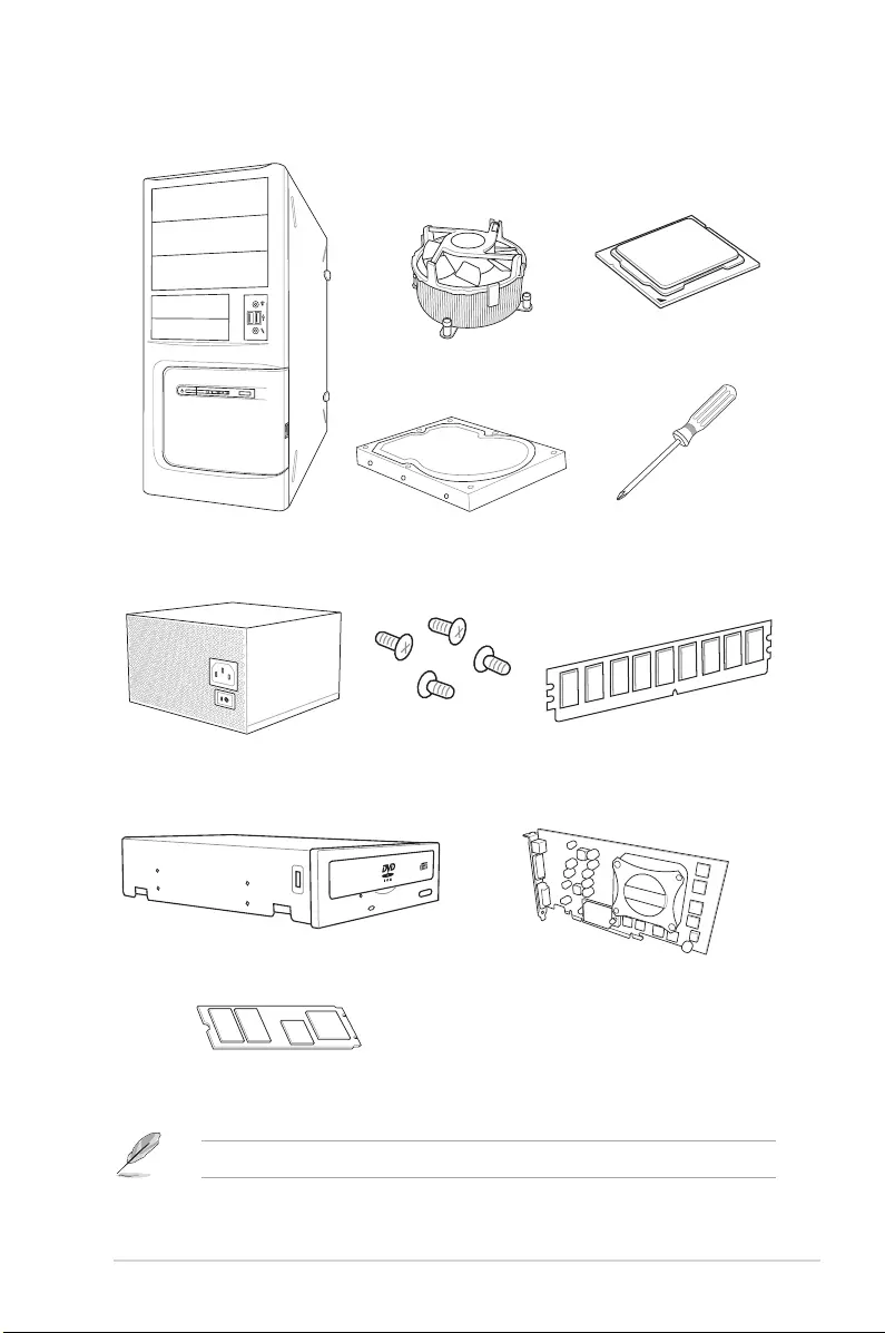
Installation tools and components
The tools and components in the table above are not included in the motherboard package.
PC chassis
Power supply unit
Intel® LGA 2066 compatible CPU Fan
Intel® LGA 2066 CPU
DIMM
SATA hard disk drive
Graphics card
Phillips (cross) screwdriver
SATA optical disc drive (optional)
M.2 SSD module (optional)
1 bag of screws

xviii

ASUS PRIME X299-A II 1-1
Chapter 1
Product Introduction
1
Chapter 1: Product Introduction
• Unplugthepowercordfromthewallsocketbeforetouchinganycomponent.
• Beforehandlingcomponents,useagroundedwriststraportouchasafelygrounded
objectorametalobject,suchasthepowersupplycase,toavoiddamagingthemdue
tostaticelectricity.
• HoldcomponentsbytheedgestoavoidtouchingtheICsonthem.
• Wheneveryouuninstallanycomponent,placeitonagroundedantistaticpadorinthe
bagthatcamewiththecomponent.
• Beforeyouinstallorremoveanycomponent,ensurethattheATXpowersupplyis
switchedofforthepowercordisdetachedfromthepowersupply.Failuretodoso
maycauseseveredamagetothemotherboard,peripherals,orcomponents.
1.1 Before you proceed
Takenoteofthefollowingprecautionsbeforeyouinstallmotherboardcomponentsorchange
anymotherboardsettings.
1-2 Chapter 1: Product Introduction
Chapter 1
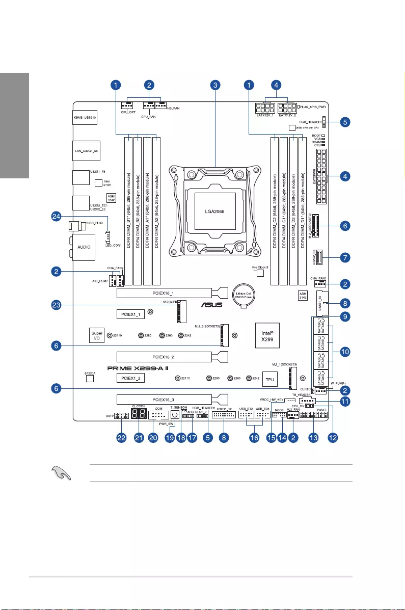
RefertoInternal connectorsandRear panel featuresformoreinformation.
1.2 Motherboard layout

ASUS PRIME X299-A II 1-3
Chapter 1
Layout contents Page
1. DIMMslots 1-5
2. Fanandpumpconnectors 1-22
3. CPUsocket 1-4
4. Powerconnectors 1-23
5. AURARGBLEDconnectors 1-18
6. M.2slot 1-24
7. USB3.2Gen2connector 1-17
8. USB3.2Gen1connectors 1-17
9. ClearRTCRAMjumper 1-10
10. SATA6Gb/sconnectors 1-13
11. Thunderboltconnector 1-14
12. CPUOverVoltagejumper 1-11
13. SystemPanelconnector 1-15
14. Nodeconnector 1-14
15. VROCKeyconnector 1-16
16. USB2.0connector 1-16
17. AddressableRGBLEDconnector 1-19
18. Thermalsensorconnector 1-20
19. Powerbutton 1-9
20. Serialportconnector 1-21
21. Q-CodeLED 1-12
22. FrontPanelAudioconnector 1-21
23. M.2Wi-Fislot 1-25
24. RearI/OCoverLEDconnector 1-20
1-4 Chapter 1: Product Introduction
Chapter 1
1.3 Central Processing Unit (CPU)
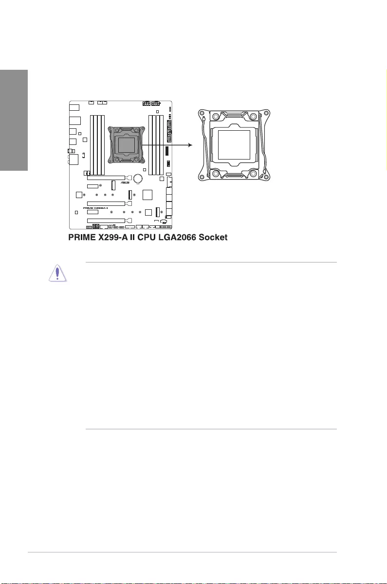
ThemotherboardcomeswithasurfacemountLGA2066socketdesignedfortheIntel®
Core™X-seriesProcessors.
• EnsurethatyouinstallthecorrectCPUdesignedforLGA2066socketonly.DONOT
installaCPUdesignedforothersocketsontheLGA2066socket.
• TheCPUtsinonlyonecorrectorientation.DONOTforcetheCPUintothesocketto
preventbendingtheconnectorsonthesocketanddamagingtheCPU.
• EnsurethatallpowercablesareunpluggedbeforeinstallingtheCPU.
• Uponpurchaseofthemotherboard,ensurethatthePnPcapisonthesocketand
thesocketcontactsarenotbent.ContactyourretailerimmediatelyifthePnPcap
ismissing,orifyouseeanydamagetothePnPcap/socketcontacts/motherboard
components.ASUSwillshoulderthecostofrepaironlyifthedamageisshipment/
transit-related.
• Keepthecapafterinstallingthemotherboard.ASUSwillprocessReturnMerchandise
Authorization(RMA)requestsonlyifthemotherboardcomeswiththecaponthe
LGA2066socket.
• Theproductwarrantydoesnotcoverdamagetothesocketcontactsresultingfrom
incorrectCPUinstallation/removal,ormisplacement/loss/incorrectremovalofthePnP
cap.
ASUS PRIME X299-A II 1-5
Chapter 1
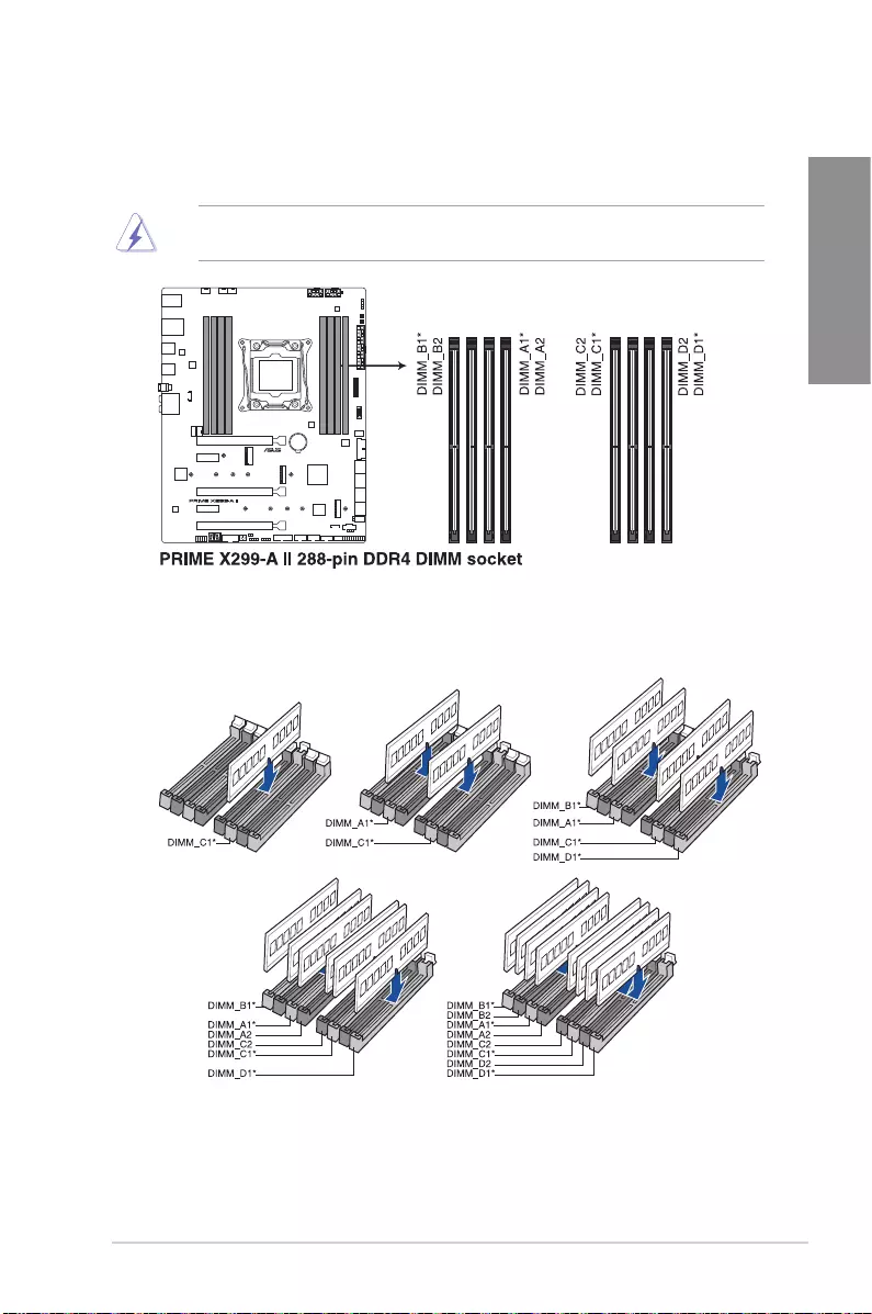
Recommended memory configurations
Intel® Core™ X-series Processors (6-core or above)
1.4 System memory
ThemotherboardcomeswithDualInlineMemoryModules(DIMM)slotsdesignedforDDR4
(DoubleDataRate4)memorymodules.
ADDR4memorymoduleisnotcheddifferentlyfromaDDR,DDR2,orDDR3module.DO
NOTinstallaDDR,DDR2,orDDR3memorymoduletotheDDR4slot.

1-6 Chapter 1: Product Introduction
Chapter 1
Memory configurations
Youmayinstall4GB,8GB,16GB,and32GBunbufferedandnon-ECCDDR4DIMMsinto
theDIMMsockets.
• ThedefaultmemoryoperationfrequencyisdependentonitsSerialPresenceDetect
(SPD),whichisthestandardwayofaccessinginformationfromamemorymodule.
Underthedefaultstate,somememorymodulesforoverclockingmayoperateata
lowerfrequencythanthevendor-markedvalue.
• Forsystemstability,useamoreefcientmemorycoolingsystemtosupportafull
memoryloadoroverclockingcondition.
• AlwaysinstalltheDIMMSwiththesameCASLatency.Foranoptimumcompatibility,
werecommendthatyouinstallmemorymodulesofthesameversionordatacode
(D/C)fromthesamevendor.Checkwiththevendortogetthecorrectmemory
modules.
• VisittheASUSwebsiteforthelatestQVL.
ASUS PRIME X299-A II 1-7
Chapter 1
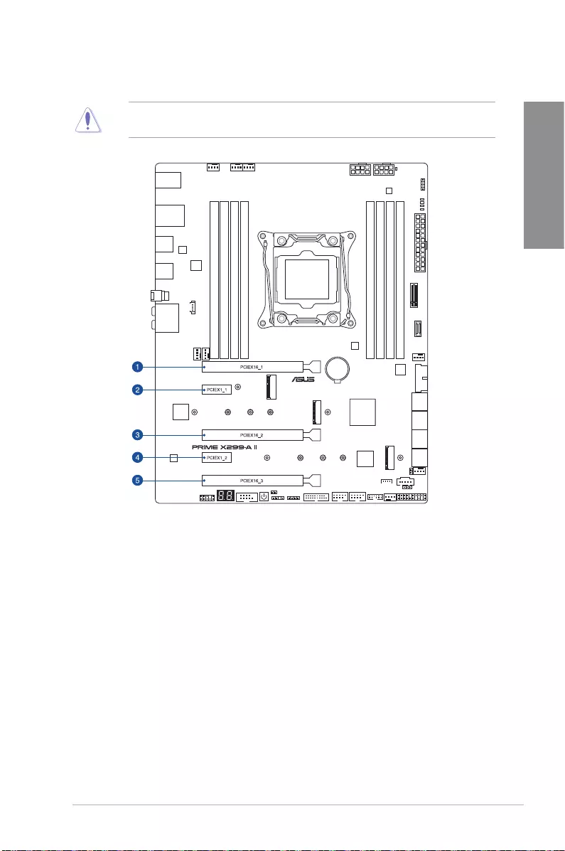
1.5 Expansion slots
Unplugthepowercordbeforeaddingorremovingexpansioncards.Failuretodosomay
causeyouphysicalinjuryanddamagemotherboardcomponents.
1-8 Chapter 1: Product Introduction
Chapter 1
• WerecommendthatyouprovidesufcientpowerwhenrunningCrossFireX™orSLI®
mode.
• Ensuretoconnectboth8-pinpowerplugswhenrunningCrossFireX™orSLI®mode.
• Connectachassisfantothechassisfanconnectorswhenusingmultiplegraphics
cardsforbetterthermalenvironment.
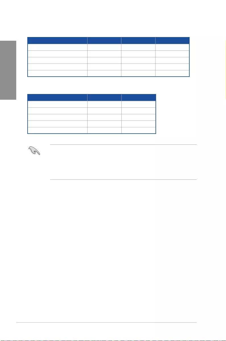
48 and 44-Lane CPUs
28-Lane CPUs
Slot Description Single VGA Dual VGA Triple VGA
1. PCIEX16_1 X16 X16 X16
2. PCIEX1_1 —
3. PCIEX16_2 —X16 X16
4. PCIEX1_2 —
5. PCIEX16_3 — — X8
Slot Description Single VGA Dual VGA
1. PCIEX16_1 X16 X16
2. PCIEX1_1 — —
3. PCIEX16_2 —X8
4. PCIEX1_2 — —
5. PCIEX16_3 — —
ASUS PRIME X299-A II 1-9
Chapter 1
1.6 Onboard buttons
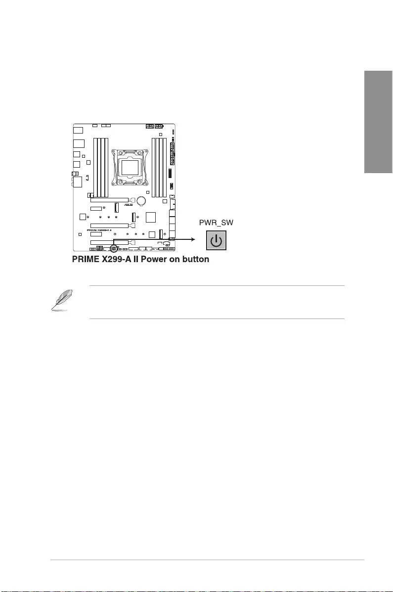
1. Power button
PressthePowerbuttontopowerupthesystem,orputthesystemintosleeporsoft-off
mode(dependingontheoperatingsystemsettings).
Thebuttonalsolightsupwhenthesystemispluggedtoapowersource,indicatingthatyou
shouldshutdownthesystemandunplugthepowercablebeforeremovingorinstallingany
motherboardcomponent.
1-10 Chapter 1: Product Introduction
Chapter 1
1.7 Onboard jumpers
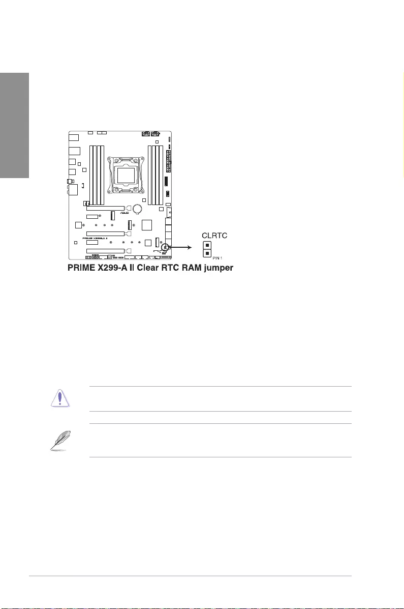
ToerasetheRTCRAM:
1. TurnOFFthecomputerandunplugthepowercord.
2. Short-circuitpin1-2withametalobjectorjumpercapforabout5-10seconds.
3. PlugthepowercordandturnONthecomputer.
4. Holddownthe<Del>keyduringthebootprocessandenterBIOSsetuptore-
enterdata.
DONOTshort-circuitthepinsexceptwhenclearingtheRTCRAM.Short-circuitingor
placingajumpercapwillcausesystembootfailure!
Ifthestepsabovedonothelp,removetheonboardbuttoncellbatteryandmovethejumper
againtocleartheCMOSRTCRAMdata.AfterclearingtheCMOS,reinstallthebuttoncell
battery.
1. Clear RTC RAM jumper
TheClearRTCRAMjumperallowsyoutocleartheRealTimeClock(RTC)RAM
intheCMOS,whichcontainsthedate,time,systempasswords,andsystemsetup
parameters.
ASUS PRIME X299-A II 1-11
Chapter 1
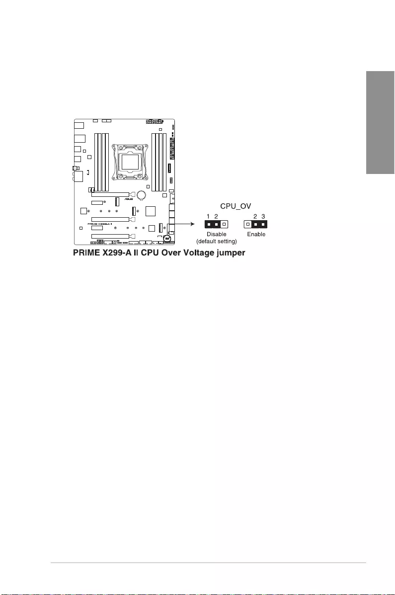
2. CPU Over Voltage jumper
TheCPUOverVoltagejumperallowsyoutosetahigherCPUvoltageforaexible
overclockingsystem(dependingonthetypeoftheinstalledCPU).Settopins2-3to
increasetheCPUvoltagesetting,orsettopins1-2tousethedefaultCPUvoltage
setting.
1-12 Chapter 1: Product Introduction
Chapter 1
1.8 Onboard LEDs
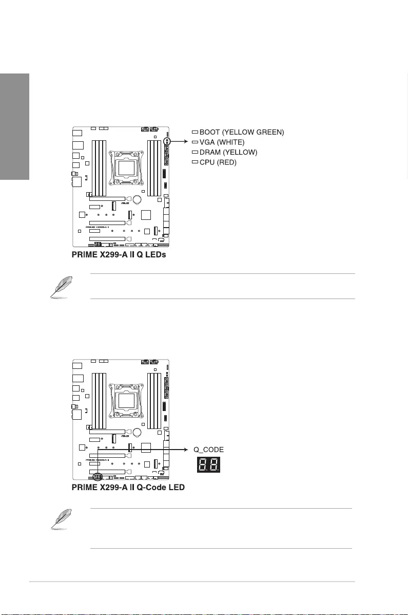
1. Q LEDs
TheQLEDscheckkeycomponents(CPU,DRAM,VGA,andbootingdevices)during
themotherboardbootingprocess.Ifanerrorisfound,thecriticalcomponent’sLED
stayslitupuntiltheproblemissolved.
TheQLEDsprovidethemostprobablecauseofanerrorcodeasastartingpointfor
troubleshooting.Theactualcausemayvaryfromcasetocase.
2. Q-Code LED
TheQ-CodeLEDdesignprovidesyouwitha2-digiterrorcodethatdisplaysthesystem
status.
• TheQ-CodeLEDsprovidethemostprobablecauseofanerrorcodeasastarting
pointfortroubleshooting.Theactualcausemayvaryfromcasetocase.
• PleaserefertotheQ-CodetableintheAppendixsectionformoredetails.
ASUS PRIME X299-A II 1-13
Chapter 1
1.9 Internal connectors
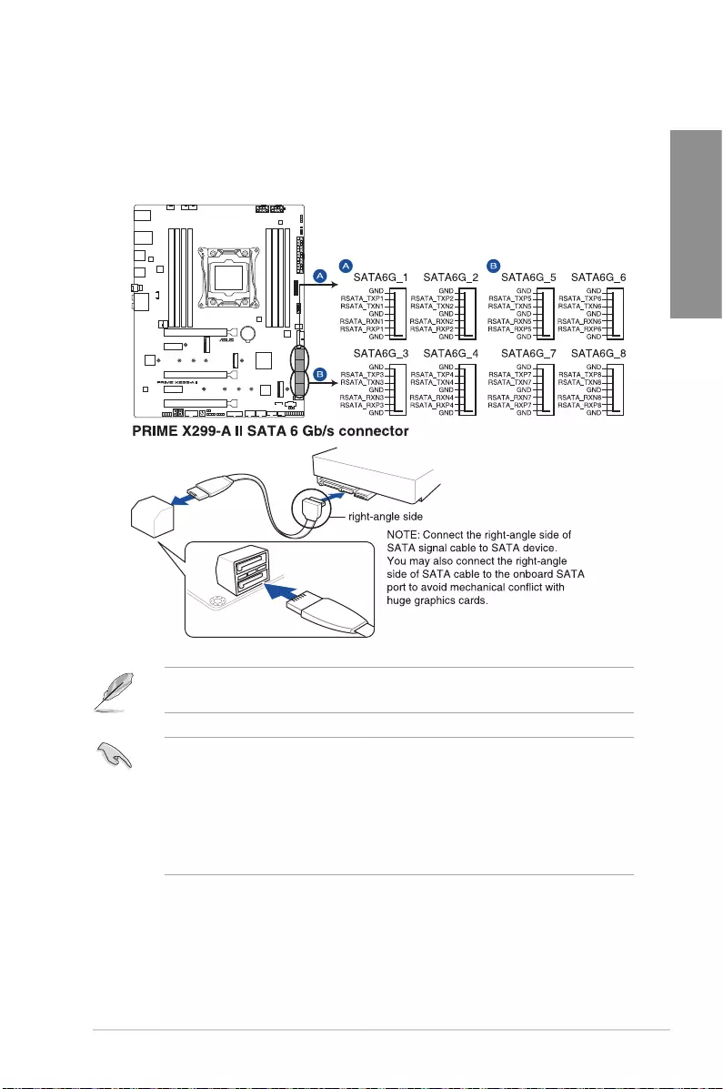
1. SATA 6 Gb/s connectors
TheSATA6Gb/sconnectorallowsyoutoconnectSATAdevicessuchasopticaldisc
drivesandharddiskdrivesviaaSATAcable.
• Theconnectorsaresetto[IRST Mode]bydefault.
• TheM.2_2socketsharesbandwidthwithSATA6G_1portwhenusingM.2SATA
devices.
• TheSATA6G_7portsharesbandwidthwithPCIEX1_2.
• BeforecreatingaRAIDset,refertotheRAID Configuration Guide.Youcan
downloadtheRAID Configuration GuidefromtheASUSwebsite.
IfyouinstalledSATAstoragedevices,youcancreateaRAID0,1,5,and10conguration
withtheIntel®RapidStorageTechnologythroughtheonboardIntel®X299chipset.
1-14 Chapter 1: Product Introduction
Chapter 1
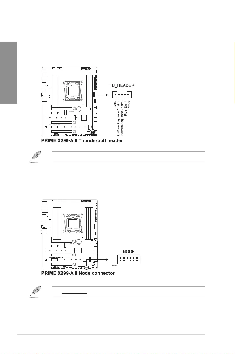
2. Thunderbolt connector
TheThunderboltconnectorallowsyoutoconnectanadd-onThunderboltI/Ocard
thatsupportsIntel’sThunderboltTechnology,allowingyoutoconnectuptosix
Thunderbolt-enableddevicesandaDisplayPort-enableddisplayinadaisy-chain
conguration.
Theadd-onThunderboltI/OcardandThunderboltcablesarepurchasedseparately.
3. Node connector
TheNodeconnectorallowsyoutoconnectNodecompatibledevices.
Visitwww.asus.comformoreinformationaboutthedevicesandthelatestcompatibilitylist.
ASUS PRIME X299-A II 1-15
Chapter 1
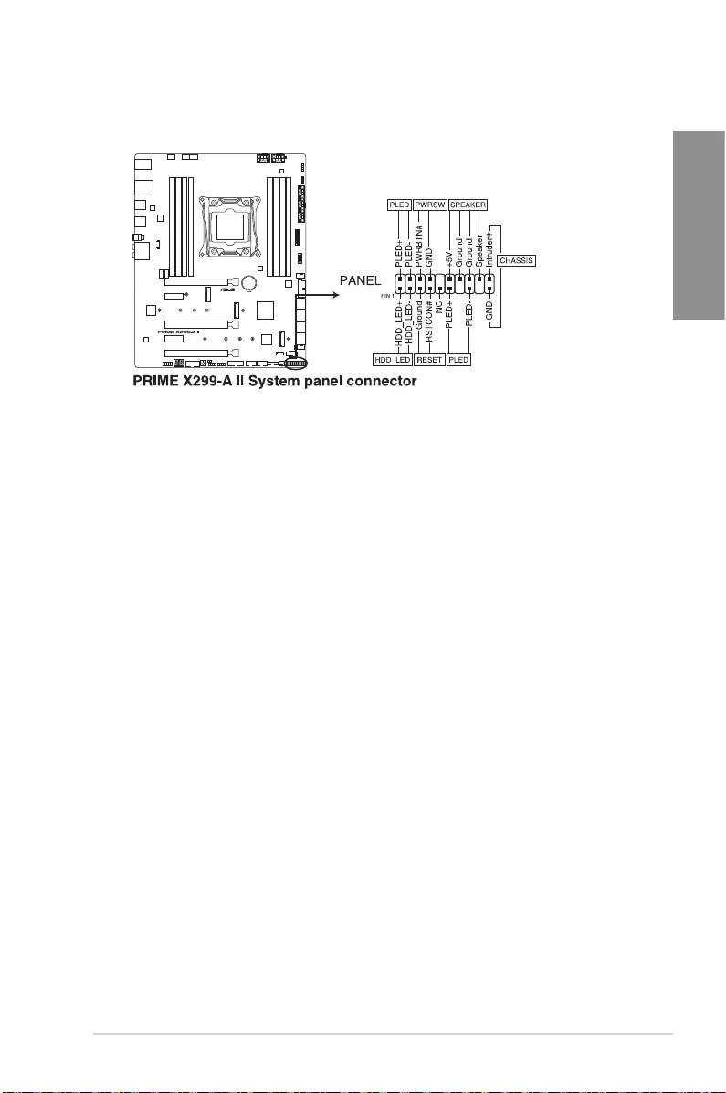
• SystemPowerLEDconnector(PLED)
The2-pinand/or3-1pinconnectorsallowyoutoconnecttheSystemPowerLED.
TheSystemPowerLEDlightsupwhenthesystemisconnectedtoapowersource,or
whenyouturnonthesystempower,andblinkswhenthesystemisinsleepmode.
• StorageDeviceActivityLEDconnector(HDD_LED)
The2-pinconnectorallowsyoutoconnecttheStorageDeviceActivityLED.The
StorageDeviceActivityLEDlightsuporblinkswhendataisreadfromorwrittentothe
storagedeviceorstoragedeviceadd-oncard.
• SystemWarningSpeakerconnector(SPEAKER)
The4-pinconnectorallowsyoutoconnectthechassis-mountedsystemwarning
speaker.Thespeakerallowsyoutohearsystembeepsandwarnings.
• PowerButton/Soft-offButtonconnector(PWRSW)
The3-1pinconnectorallowsyoutoconnectthesystempowerbutton.Pressthe
powerbuttontopowerupthesystem,orputthesystemintosleeporsoft-offmode
(dependingontheoperatingsystemsettings).
• Resetbuttonconnector(RESET)
The2-pinconnectorallowsyoutoconnectthechassis-mountedresetbutton.Pressthe
resetbuttontorebootthesystem.
• Chassisintrusionconnector(CHASSIS)
The2-pinconnectorallowsyoutoconnectthechassis-mountedintrusiondetection
sensororswitch.Thechassisintrusionsensororswitchsendsahigh-levelsignalto
theconnectorwhenachassiscomponentisremovedorreplaced,thesignalisthen
generatedasachassisintrusionevent.
4. System Panel connector
TheSystemPanelconnectorsupportsseveralchassis-mountedfunctions.
1-16 Chapter 1: Product Introduction
Chapter 1
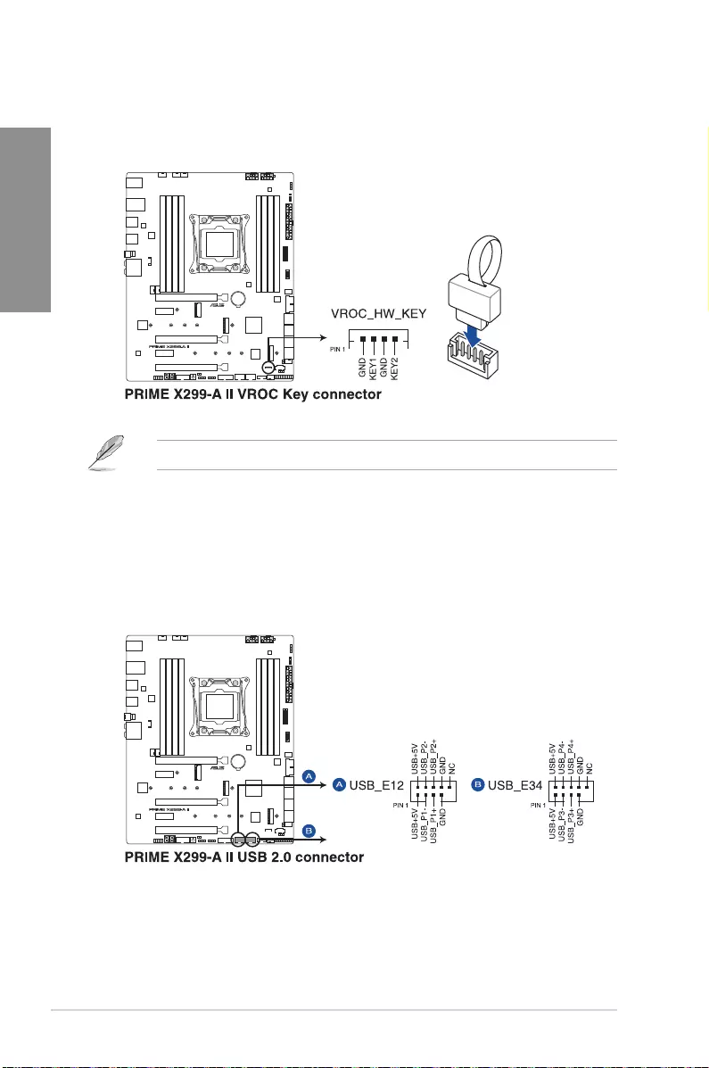
5. VROCKeyconnector
TheVROC(VirtualRaidonCPU)KeyconnectorallowsyoutoconnectaVROC
hardwarekeytoenableadditionalCPURAIDfunctionswithIntel®CPURSTe.
TheVROChardwarekeyispurchasedseparately.
6. USB 2.0 connector
TheUSB2.0connectorallowsyoutoconnectaUSBmoduleforadditionalUSB
2.0ports.TheUSB2.0connectorprovidesdatatransferspeedsofupto480MB/s
connectionspeed.
ASUS PRIME X299-A II 1-17
Chapter 1
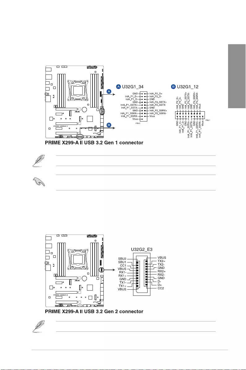
7. USB 3.2 Gen 1 connector
TheUSB3.2Gen1connectorallowsyoutoconnectaUSB3.2Gen1modulefor
additionalUSB3.2Gen1ports.TheUSB3.2Gen1connectorprovidesdatatransfer
speedsofupto5Gb/s
TheUSB3.2Gen1moduleispurchasedseparately.
ThepluggedUSB3.2Gen1devicemayrunonxHCIorEHCImodedependingonthe
operatingsystem’ssetting.
8. USB 3.2 Gen 2 connector
TheUSB3.2Gen2connectorallowsyoutoconnectaUSB3.2Gen2modulefor
additionalUSB3.2Gen2ports.TheUSB3.2Gen2connectorprovidesdatatransfer
speedsofupto10Gb/s.
TheUSB3.2Gen2moduleispurchasedseparately.
1-18 Chapter 1: Product Introduction
Chapter 1
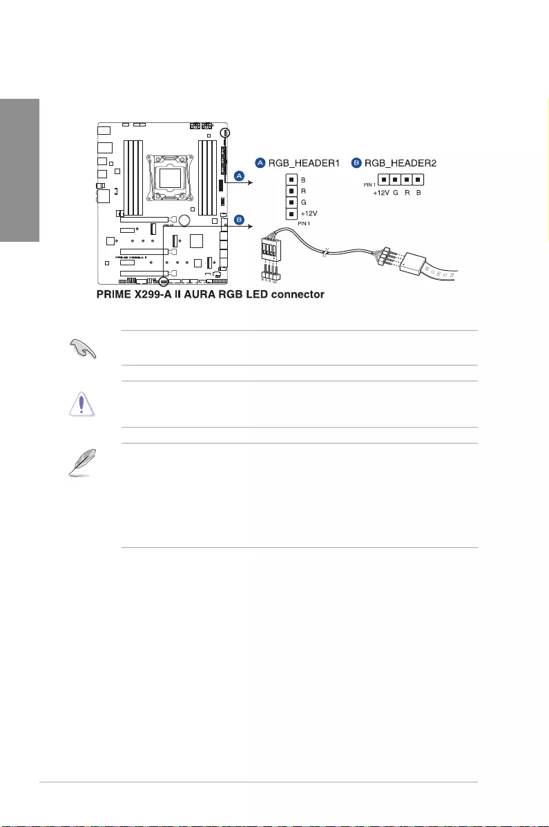
9. AURA RGB LED connector
TheAURARGBLEDconnectorallowsyoutoconnectRGBLEDstrips.
TheAURARGBLEDconnectorsupports5050RGBmulti-colorLEDstrips(12V/G/R/B),
withamaximumpowerratingof3A(12V),andnolongerthan3m.
Beforeyouinstallorremoveanycomponent,ensurethatthepowersupplyisswitchedoff
orthepowercordisdetachedfromthepowersupply.Failuretodosomaycausesevere
damagetothemotherboard,peripherals,orcomponents.
• ActuallightingandcolorwillvarywithLEDstrip.
• IfyourLEDstripdoesnotlightup,checkiftheRGBLEDextensioncableandthe
RGBLEDstripisconnectedinthecorrectorientation,andthe12Vconnectoris
alignedwiththe12Vheaderonthemotherboard.
• TheLEDstripwillonlylightupwhenthesystemispoweredon.
• TheLEDstripispurchasedseparately.
ASUS PRIME X299-A II 1-19
Chapter 1
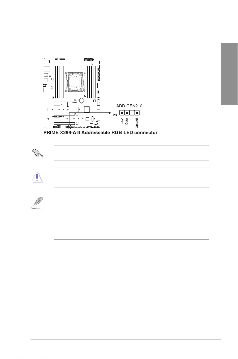
10. Addressable RGB LED connector
TheAddressableRGBLEDconnectorallowsyoutoconnectindividuallyaddressable
RGBWS2812BLEDstripsorWS2812BbasedLEDstrips.
TheAddressableRGBLEDconnectorsupportsWS2812BaddressableRGBLEDstrips
(5V/Data/Ground),withamaximumpowerratingof3A(5V)andamaximumof120LEDs.
Beforeyouinstallorremoveanycomponent,ensurethatthepowersupplyisswitchedoff
orthepowercordisdetachedfromthepowersupply.Failuretodosomaycausesevere
damagetothemotherboard,peripherals,orcomponents.
• ActuallightingandcolorwillvarywithLEDstrip.
• IfyourLEDstripdoesnotlightup,checkiftheaddressableRGBLEDstripis
connectedinthecorrectorientation,andthe5Vconnectorisalignedwiththe5V
headeronthemotherboard.
• TheaddressableRGBLEDstripwillonlylightupwhenthesystemispoweredon.
• TheaddressableRGBLEDstripispurchasedseparately.
1-20 Chapter 1: Product Introduction
Chapter 1
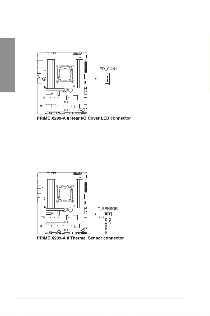
11. Rear I/O Cover LED connector
TheRearI/OCoverLEDconnectorisforconnectingtheLEDboardonyourrearI/O
cover.
12. Thermal Sensor connector
TheThermalSensorconnectorallowsyoutoconnectasensortomonitorthe
temperatureofthedevicesandthecriticalcomponentsinsidethemotherboard.
Connectthethermalsensorandplaceitonthedeviceorthemotherboard’scomponent
todetectitstemperature.
ASUS PRIME X299-A II 1-21
Chapter 1
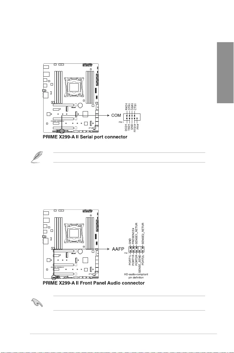
13. Serial Port connector
TheSerial(COM)Portconnectorallowsyoutoconnectaserialportmodule.Connect
theserialportmodulecabletothisconnector,theninstallthemoduletoaslotopening
onthesystemchassis.
Theserialportmoduleispurchasedseparately.
14. Front Panel Audio connector
Thefrontpanelaudioconnectorisforachassis-mountedfrontpanelaudioI/Omodule
thatsupportsHDAudio.ConnectoneendofthefrontpanelaudioI/Omodulecableto
thisconnector.
Werecommendthatyouconnectahigh-denitionfrontpanelaudiomoduletothis
connectortoavailofthemotherboard’shigh-denitionaudiocapability.
1-22 Chapter 1: Product Introduction
Chapter 1
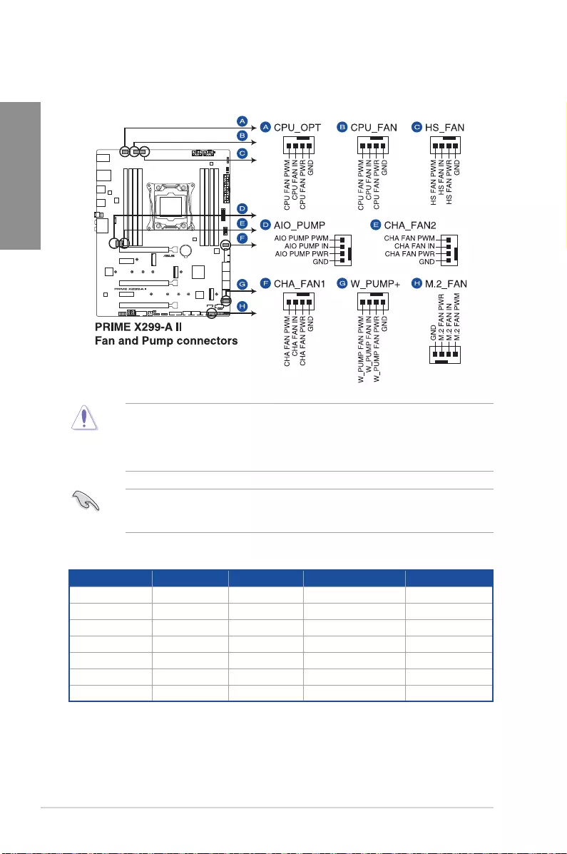
15. Fan and Pump connectors
TheFanandPumpconnectorsallowyoutoconnectfansorpumpstocoolthesystem.
• ConnectthefanofyourwatercoolingkittotheAIO_PUMPconnector.
• W_PUMP+functionsupportdependsonwatercoolingdevice.
• DONOTforgettoconnectthefancablestothefanconnectors.Insufcientairow
insidethesystemmaydamagethemotherboardcomponents.Thesearenotjumpers!
Donotplacejumpercapsonthefanconnectors!
• Ensurethecableisfullyinsertedintotheconnector.
Header Max. Current Max. Power Default Speed Shared Control
CPU_FAN 1A 12W Q-FanControlled A
CPU_OPT 1A 12W Q-FanControlled A
CHA_FAN1 1A 12W Q-FanControlled —
CHA_FAN2 1A 12W Q-FanControlled —
AIO_PUMP 1A 12W Full-Speed —
W_PUMP+ 3A 36W Full-Speed —
HS_FAN 1A 12W Q-FanControlled —
ASUS PRIME X299-A II 1-23
Chapter 1
Ensuretoconnectboth8-pinpowerplugsunderheavyusage.
• WerecommendthatyouuseaPSUwithahigherpoweroutputwhenconguringa
systemwithmorepower-consumingdevices.Thesystemmaybecomeunstableor
maynotbootupifthepowerisinadequate.
• Ifyouwanttousetwoormorehigh-endPCIex16cards,useaPSUwith1000W
powerorabovetoensurethesystemstability.
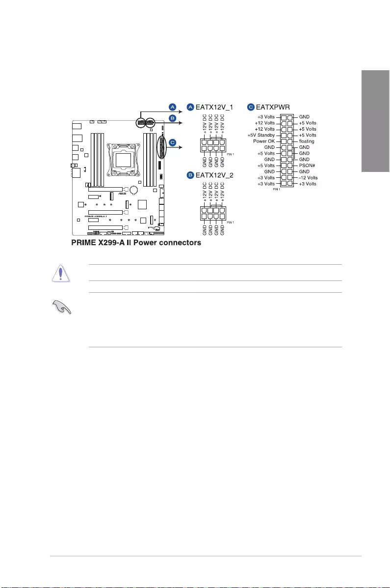
16. Power connectors
ThesePowerconnectorsallowyoutoconnectyourmotherboardtoapowersupply.
Thepowersupplyplugsaredesignedtotinonlyoneorientation,ndtheproper
orientationandpushdownrmlyuntilthepowersupplyplugsarefullyinserted.
1-24 Chapter 1: Product Introduction
Chapter 1
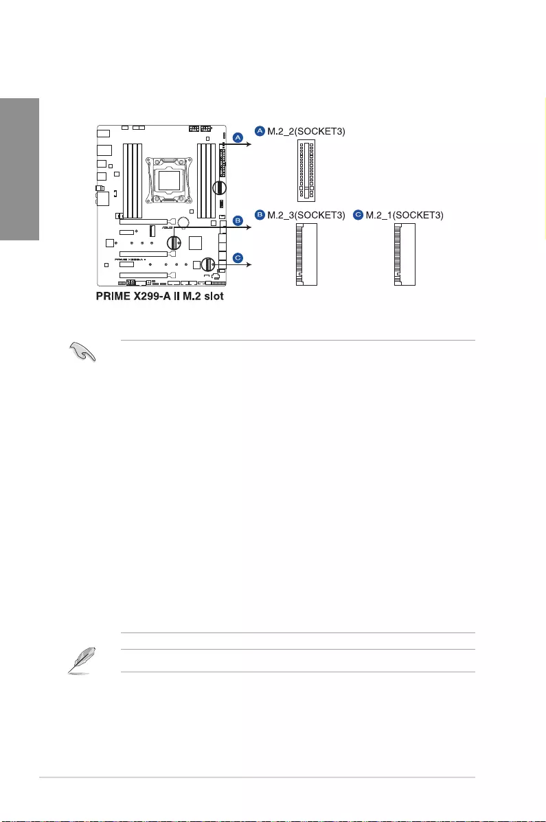
17. M.2 slot
TheM.2slotallowsyoutoinstallM.2devicessuchasM.2SSDmodules.
• For Intel® Core™ i9 10000 X-Series Processors support with Intel® Virtual RAID
on CPU (VROC):
-M.2_1socketsupportsPCIe3.0x4modeMKeydesignandtype2242/2260/
2280/22110PCIestoragedevices.
-M.2_3socketsupportsPCIe3.0x4modeMKeydesignandtype2242/2260/
2280/22110PCIestoragedevices.
• For Intel® Core™ i9 9000/7000 and i7 9000/7000 X-Series Processors support
with Intel® Virtual RAID on CPU (VROC):
-M.2_3socketssupportPCIe3.0x4modeMKeydesignandtype2242/2260/
2280/22110PCIestoragedevices.
• For Intel® X299 Chipset supports with Intel® Rapid Storage Technology
(RAID 0, 1, 5, 10):
-M.2_2socketsupportsPCIe3.0x4modeandSATAmodeverticalMKeydesign
andtype2242/2260/2280/22110PCIeandSATAstoragedevices.TheM.2_2
socketsharesbandwidthwithSATA6G_1portwhenusingM.2SATAdevices.
-M.2_1socketsupportsPCIe3.0x4modeMKeydesignandtype2242/2260/
2280/22110PCIestoragedevices.TheM.2_1PCIemodesourceisfromX299
Chipsetwhenusing44and28-laneCPU.
• TheM.2PCIemodesourcefromX299ChipsetsupportsIntel®OptaneMemory.
TheM.2SSDmoduleispurchasedseparately.
ASUS PRIME X299-A II 1-25
Chapter 1
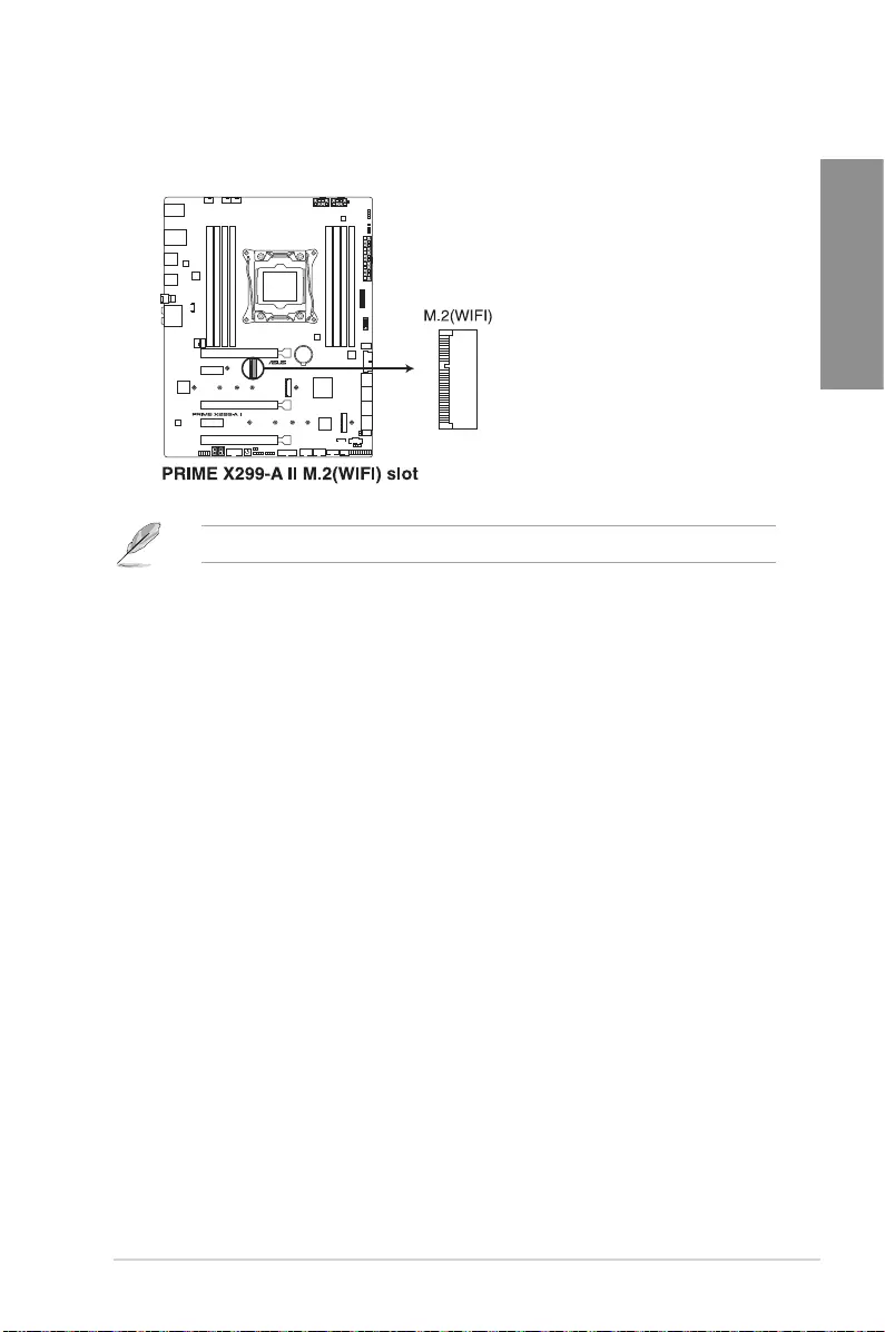
18. M.2Wi-Fislot
TheM.2Wi-FislotallowsyoutoinstallanM.2Wi-Fimodule(E-key,type2230).
TheM.2Wi-Fimoduleispurchasedseparately.

1-26 Chapter 1: Product Introduction
Chapter 1
ASUS PRIME X299-A II 2-1
Chapter 2
Basic Installation
2
2.1 Building your PC system
The diagrams in this section are for reference only. The motherboard layout may vary with
models, but the installation steps are the same for all models.
2.1.1 Motherboard installation
Chapter 2: Basic Installation
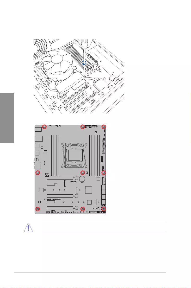
1. Place the motherboard into the chassis, ensuring that its rear I/O ports are aligned to
the chassis’ rear I/O panel.
2-2 Chapter 2: Basic Installation
Chapter 2
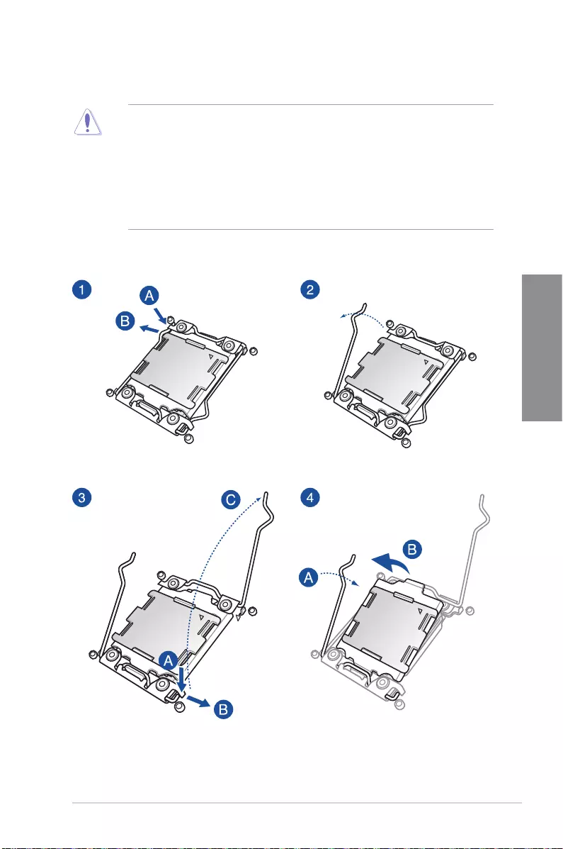
2. Place nine screws into the holes indicated by circles to secure the motherboard to the
chassis.
DO NOT overtighten the screws! Doing so can damage the motherboard.
ASUS PRIME X299-A II 2-3
Chapter 2
2.1.2 CPU installation
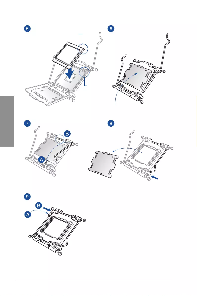
• EnsurethatyouinstallthecorrectCPUdesignedforLGA2066socketonly.
• ASUSwillnotcoverdamagesresultingfromincorrectCPUinstallation/removal,
incorrectCPUorientation/placement,orotherdamagesresultingfromnegligenceby
the user.
• Pleasenotetheorderinopening/closingthedoublelatch.Followtheinstructions
printed on the metal sealing hatch or the illustrations shown below in this manual. The
plasticcapwillpopupautomaticallyoncetheCPUisinplaceandthehatchproperly
sealed down.
2-4 Chapter 2: Basic Installation
Chapter 2
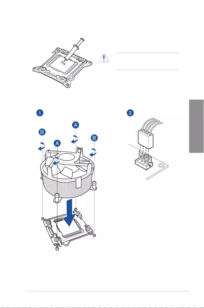
Triangle mark
Triangle
mark
ASUS PRIME X299-A II 2-5
Chapter 2
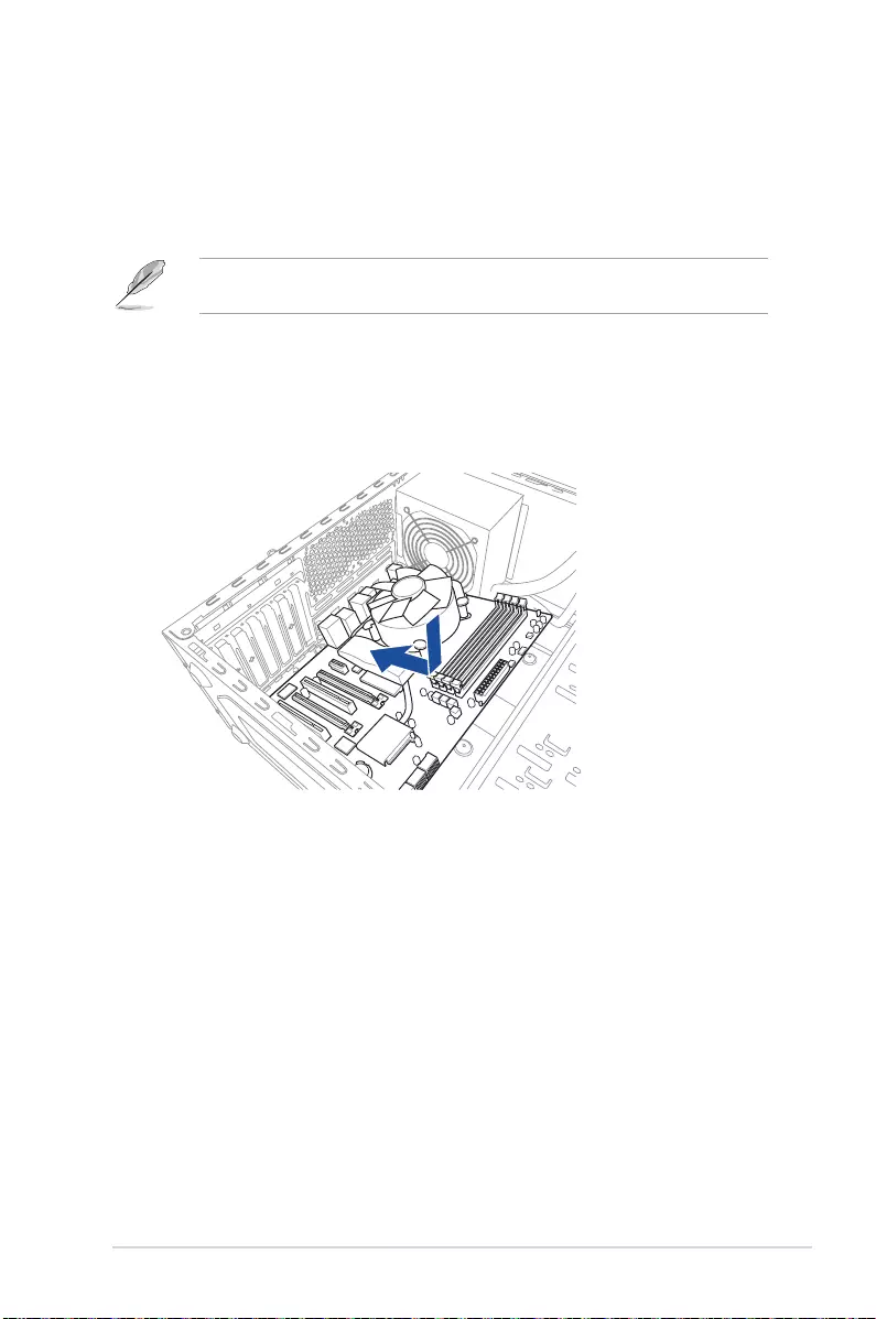
2.1.3 Cooling system installation
ApplytheThermalInterfaceMaterialtothe
CPUheatsinkandCPUbeforeyouinstall
theheatsinkandfan,ifnecessary.
To install the CPU heatsink and fan assembly
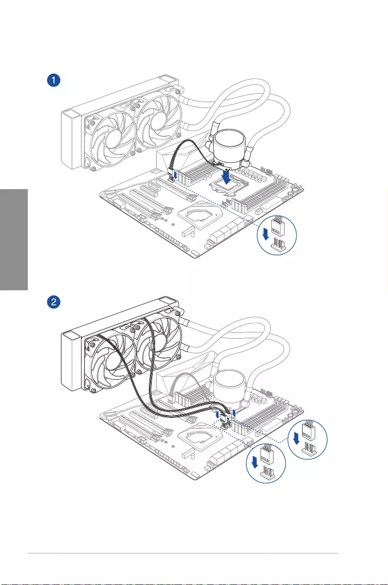
2-6 Chapter 2: Basic Installation
Chapter 2
AIO_PUMP
CPU_OPT
CPU_FAN
To install an AIO cooler
ASUS PRIME X299-A II 2-7
Chapter 2
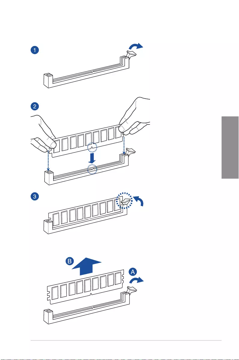
To remove a DIMM
2.1.4 DIMM installation
2-8 Chapter 2: Basic Installation
Chapter 2
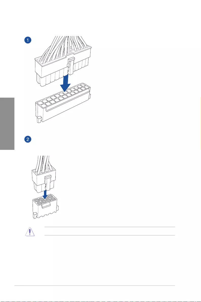
2.1.5 ATX power connection
Ensuretoconnectboth8-pinpowerplugsunderheavyusage.
ASUS PRIME X299-A II 2-9
Chapter 2
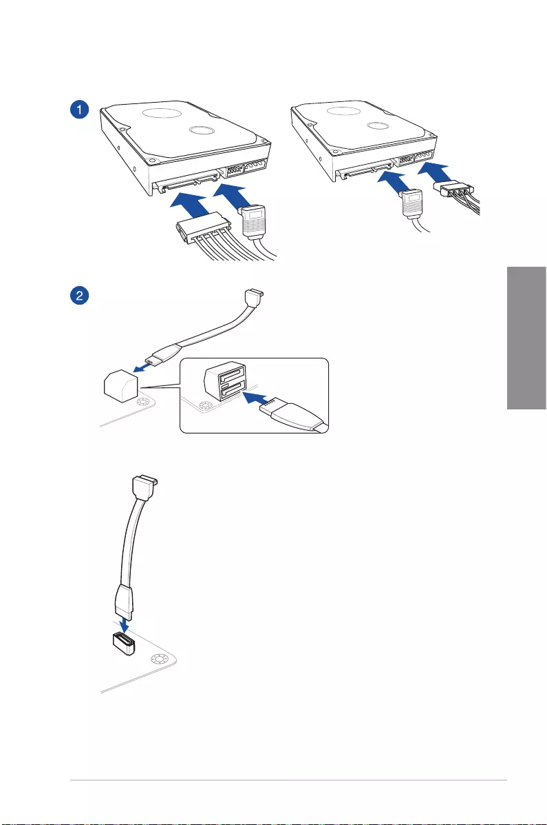
2.1.6 SATA device connection
OR
OR
2-10 Chapter 2: Basic Installation
Chapter 2
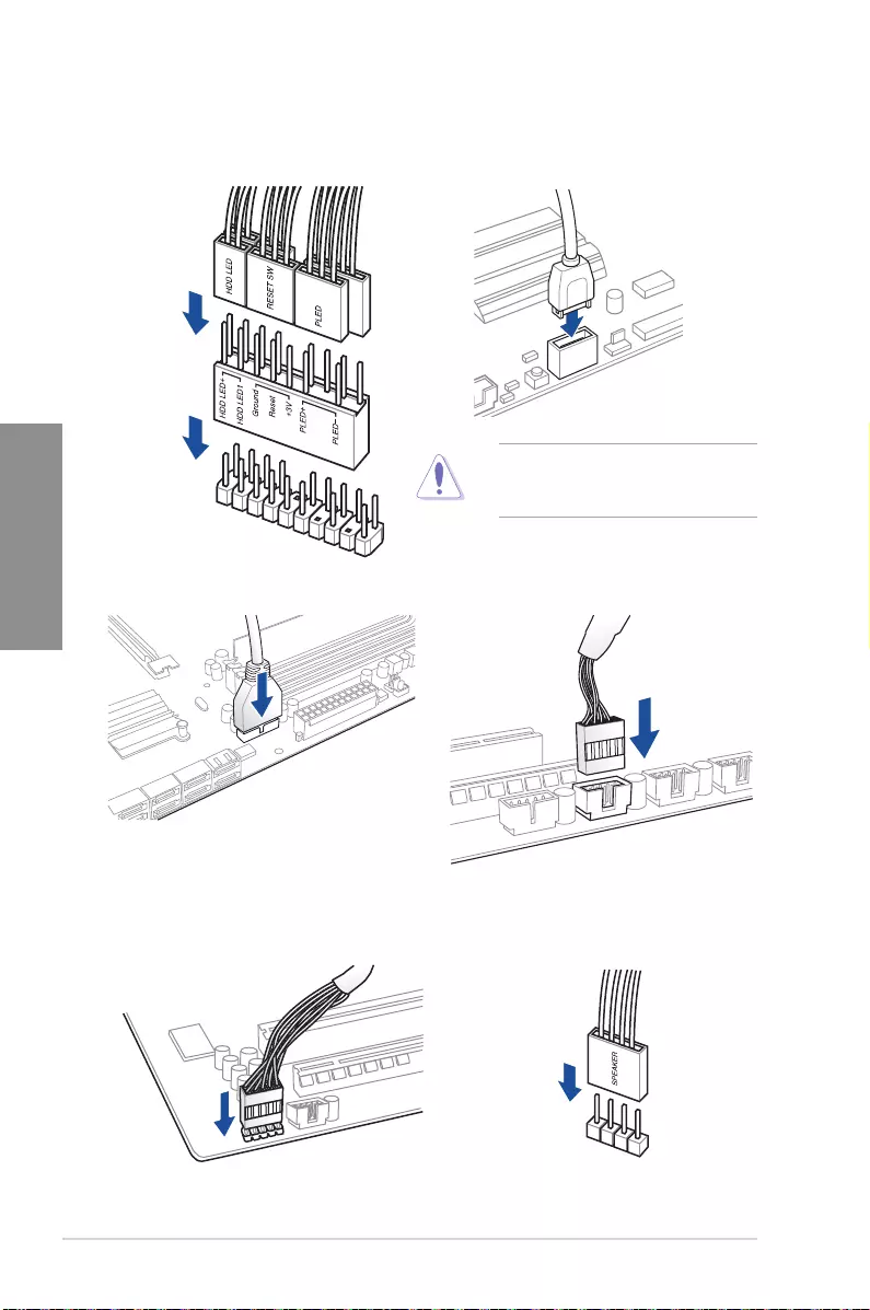
2.1.7 Front I/O connector
USB 3.2 Gen 2
To install USB 3.2 Gen 2 connectorTo install ASUS Q-Connector
Thisconnectorwillonlytinone
orientation. Push the connector until it
clicksintoplace.
USB 2.0
AAFP
To install USB 2.0 connector
To install front panel audio connector
USB 3.2 Gen 1
To install USB 3.2 Gen 1 connector
To install system speaker connector
ASUS PRIME X299-A II 2-11
Chapter 2
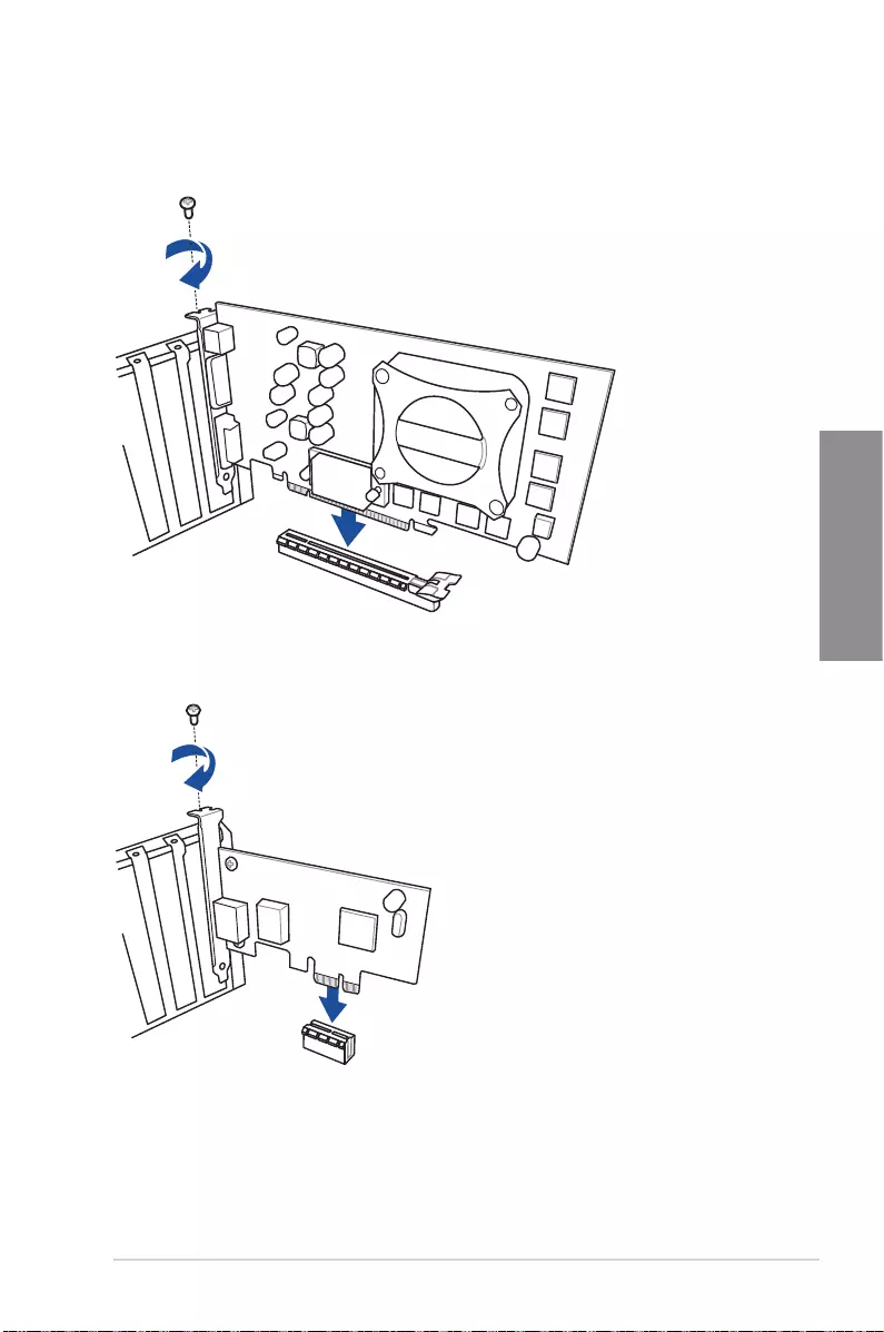
2.1.8 Expansion card installation
To install PCIe x16 cards
To install PCIe x1 cards
2-12 Chapter 2: Basic Installation
Chapter 2
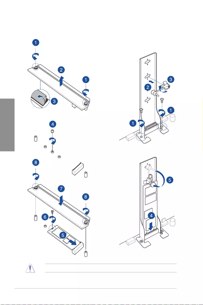
2.1.9 M.2 installation
OR
SupportedM.2typevariespermotherboard.
ASUS PRIME X299-A II 2-13
Chapter 2
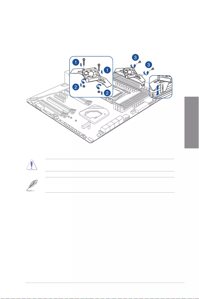
2.1.10 Fan bracket installation
To install the MOS FAN bracket and fan
Whenusinghighperformancesettingswhilstoverclocking,ensuretoinstalltheMOSFAN
bracketforadditionalfan(s).
• Youmayinstall12V(1A,12W),40mmx40mmfans.
• Thefanispurchasedseparately.
2-14 Chapter 2: Basic Installation
Chapter 2
2.2 BIOS update utility
BIOS FlashBack™
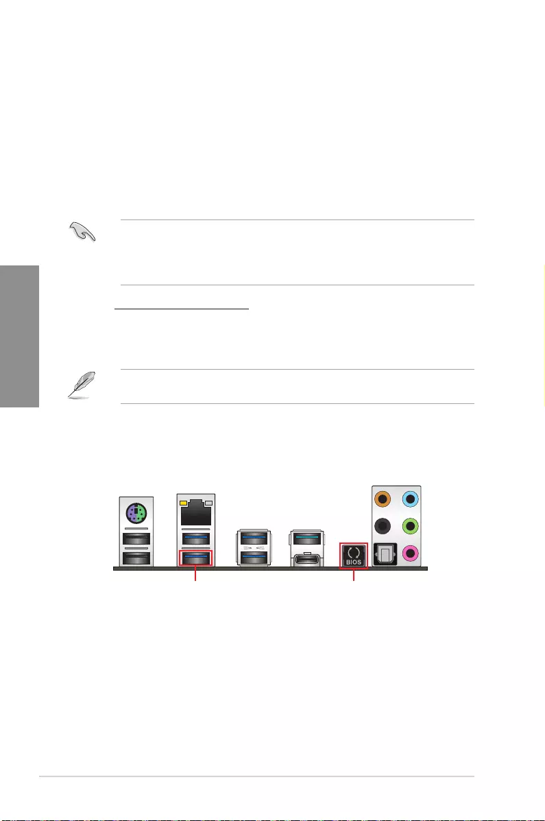
BIOSFlashBack™allowsyoutoeasilyupdatetheBIOSwithoutenteringtheexistingBIOS
oroperatingsystem.SimplyinsertaUSBstoragedevicetotheUSBport(theUSBport
holemarkedingreenontheI/Oshield)thenpresstheBIOSFlashBack™buttonforthree
secondstoautomaticallyupdatetheBIOS.
To use BIOS FlashBack™:
1. InsertaUSBstoragedevicetotheBIOSFlashBack™port.
• WerecommendyoutouseaUSB2.0storagedevicetosavethelatestBIOSversion
for better compatibility and stability.
• Refertosection2.3.1 Rear I/O connectionforthelocationoftheUSBportthat
supportsBIOSFlashBack™.
2. Visithttps://www.asus.com/support/anddownloadthelatestBIOSversionforthis
motherboard.
3. ManuallyrenametheleasX299A2.CAP, or launch the BIOSRenamer.exe
applicationtoautomaticallyrenamethele,thencopyittoyourUSBstoragedevice.
The BIOSRenamer.exeapplicationiszippedtogetherwithyourBIOSlewhenyou
downloadaBIOSleforaBIOSFlashBack™compatiblemotherboard.
4. Shutdownyourcomputer.
5. PresstheBIOSFlashBack™buttonforthreesecondsuntiltheFlashBack™LED
blinksthreetimes,indicatingthattheBIOSFlashBack™functionisenabled.
BIOS FlashBack™ port BIOS FlashBack™ button

ASUS PRIME X299-A II 2-15
Chapter 2
6. Waituntilthelightgoesout,indicatingthattheBIOSupdatingprocessiscompleted.
FormoreBIOSupdateutilitiesinBIOSsetup,refertothesection3.11 Updating BIOS in
Chapter3.
• Donotunplugportabledisk,powersystem,orpresstheCLR_CMOSbuttonwhile
BIOSupdateisongoing,otherwiseupdatewillbeinterrupted.Incaseofinterruption,
please follow the steps again.
• Ifthelightashesforvesecondsandturnsintoasolidlight,thismeansthatthe
BIOSFlashBack™isnotoperatingproperly.Thismaybecausedbyimproper
installationoftheUSBstoragedeviceandlename/leformaterror.Ifthisscenario
happens, please restart the system to turn off the light.
• UpdatingBIOSmayhaverisks.IftheBIOSprogramisdamagedduringtheprocess
andresultstothesystem’sfailuretobootup,pleasecontactyourlocalASUSService
Center.
2-16 Chapter 2: Basic Installation
Chapter 2
2.3 Motherboard rear and audio connections
2.3.1 Rear I/O connection
Rear panel connectors
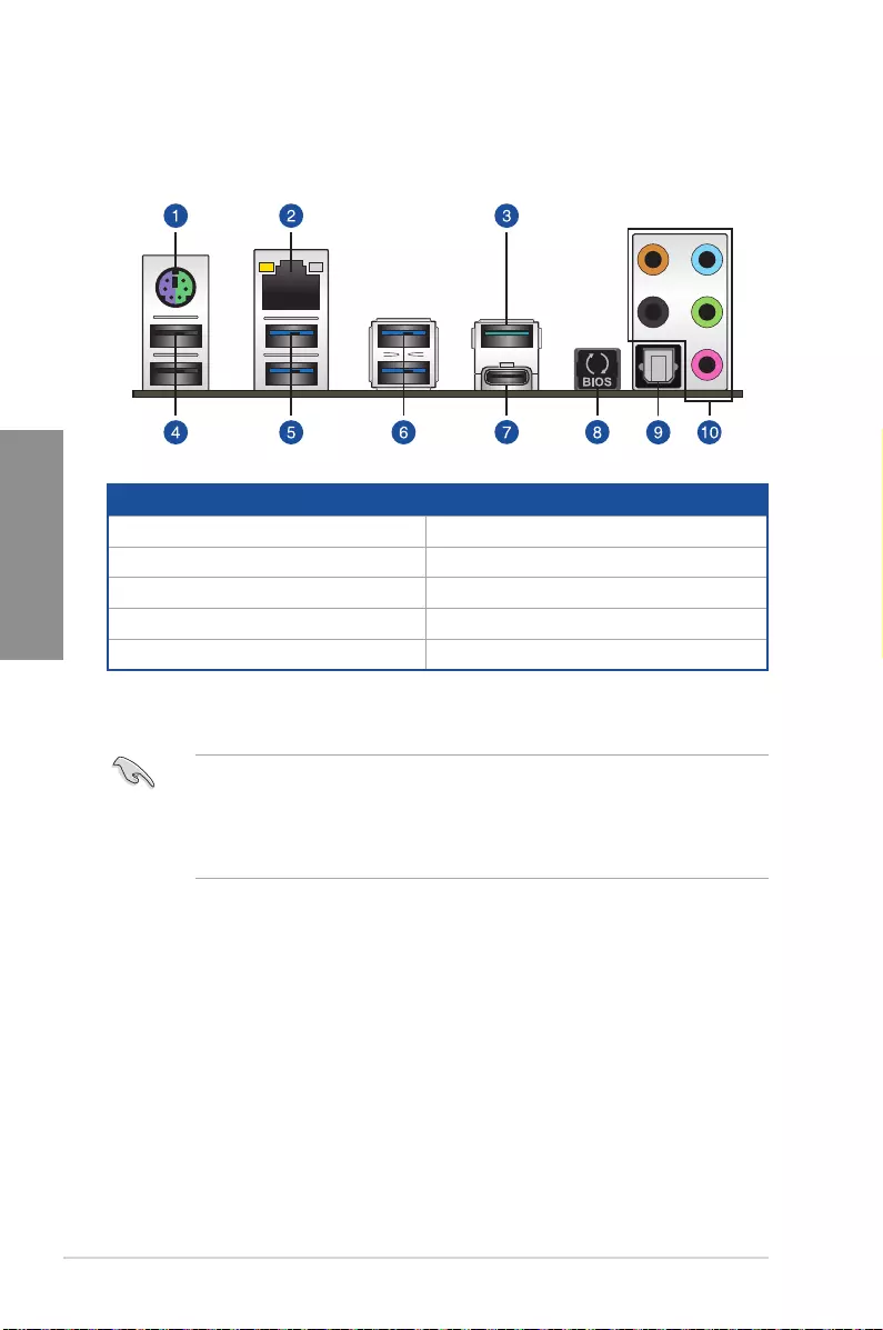
1. PS/2keyboard/mousecomboport 6. USB3.2Gen1ports7and8
2. Intel®LANport(LAN1)* 7. USB3.2Gen2Type-C™portEC1
3. USB3.2Gen2portE2 8. BIOSFlashBack™button
4. USB2.0ports9and10 9. OpticalS/PDIFOutport
5. USB3.2Gen1ports5and6 10. AudioI/Oports**
* and **: Refer to the tables on the next page for LAN port LEDs and audio port definitions.
• USB3.1Gen1/Gen2devicescanonlybeusedasdatastorageonly.
• Westronglyrecommendthatyouconnectyourdevicestoportswithmatchingdata
transferrate.PleaseconnectyourUSB3.2Gen1devicestoUSB3.2Gen1portsand
yourUSB3.2Gen2devicestoUSB3.2Gen2portsforfasterandbetterperformance
for your devices.

ASUS PRIME X299-A II 2-17
Chapter 2
* LAN ports LED indications
ACT/LINK
LED SPEED
LED
LAN port
Activity Link LED Speed LED
Status Description Status Description
Off Nolink Off 10Mbpsconnection
Orange Linked Orange 100Mbpsconnection
Orange(Blinking) Data activity Green 1Gbpsconnection
Orange(Blinking
thensteady)
Readytowakeup
fromS5mode
YoucandisabletheLANcontrollersinBIOS.Duetohardwaredesign,theLAN1port’s
LEDsmaycontinuetoblinkevenwhendisabled.
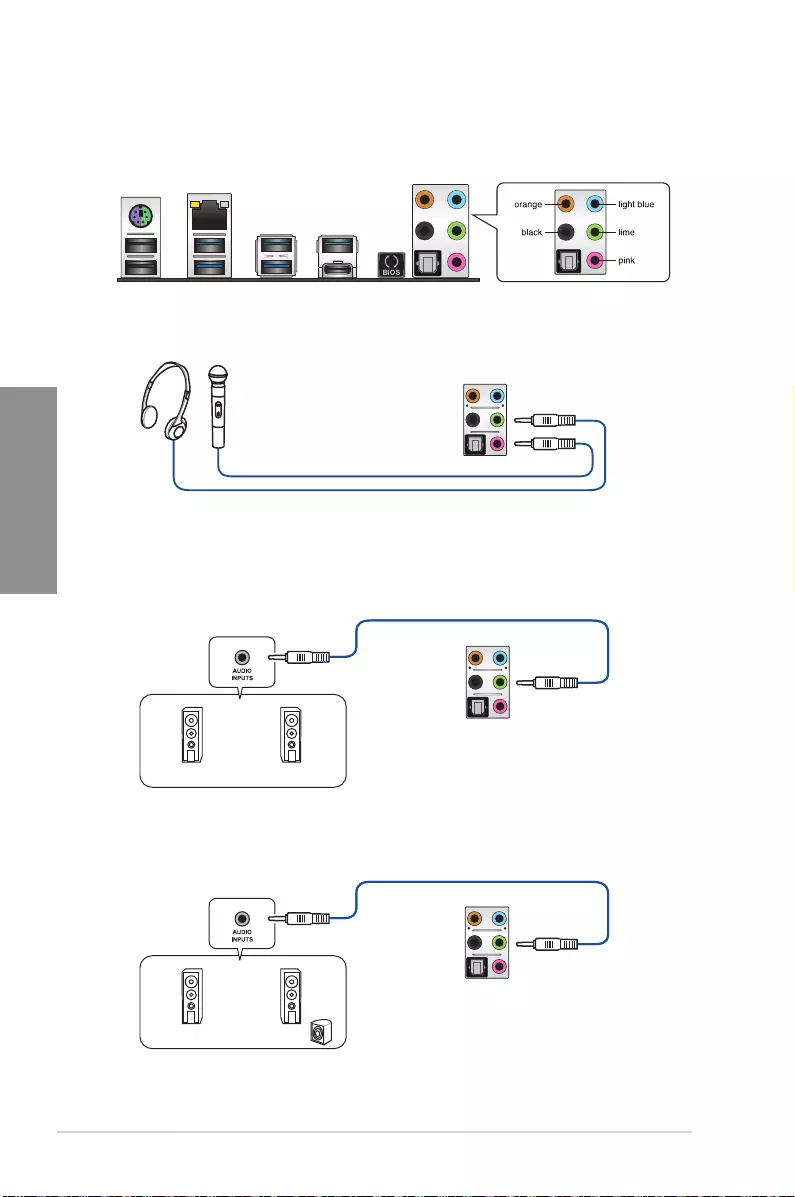
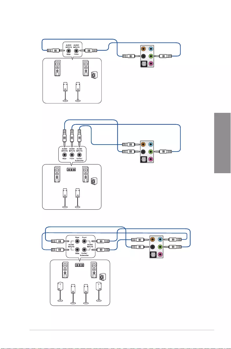
** Audio 2, 4, 5.1 or 7.1-channel configuration
Port Headset
2-channel 4-channel 5.1-channel 7.1-channel
LightBlue LineIn LineIn LineIn SideSpeakerOut
Lime LineOut FrontSpeakerOut FrontSpeakerOut FrontSpeakerOut
Pink MicIn MicIn MicIn MicIn
Orange – – Center/Sub
woofer
Center/Sub
woofer
Black –RearSpeakerOut RearSpeakerOut RearSpeakerOut
2-18 Chapter 2: Basic Installation
Chapter 2
2.3.2 Audio I/O connections
Audio I/O ports
Connect to Headphone and Mic
Connect to Stereo Speakers
Connect to 2-channel Speakers
ASUS PRIME X299-A II 2-19
Chapter 2
Connect to 4-channel Speakers
Connect to 5.1-channel Speakers
Connect to 7.1-channel Speakers

2-20 Chapter 2: Basic Installation
Chapter 2
2.4 Starting up for the first time
1. Aftermakingalltheconnections,replacethesystemcasecover.
2. Ensurethatallswitchesareoff.
3. Connectthepowercordtothepowerconnectoratthebackofthesystemchassis.
4. Connectthepowercordtoapoweroutletthatisequippedwithasurgeprotector.
5. Turn on the devices in the following order:
a. Monitor
b. ExternalSCSIdevices(startingwiththelastdeviceonthechain)
c. Systempower
6. Afterapplyingpower,thesystempowerLEDonthesystemfrontpanelcaselightsup.
ForsystemswithATXpowersupplies,thesystemLEDlightsupwhenyoupressthe
ATXpowerbutton.Ifyourmonitorcomplieswiththe“green”standardsorifithasa
“powerstandby”feature,themonitorLEDmaylightuporchangefromorangetogreen
afterthesystemLEDturnson.
Thesystemthenrunsthepower-onselftests(POST).Whilethetestsarerunning,the
BIOSbeeps(refertotheBIOSbeepcodestable)oradditionalmessagesappearon
thescreen.Ifyoudonotseeanythingwithin30secondsfromthetimeyouturnedon
thepower,thesystemmayhavefailedapower-ontest.Checkthejumpersettingsand
connections or call your retailer for assistance.
BIOS Beep Description
One short beep VGAdetected
Quickbootsettodisabled
Nokeyboarddetected
One continuous beep followed by two
shortbeepsthenapause(repeated)
No memory detected
One continuous beep followed by three
short beeps
NoVGAdetected
One continuous beep followed by four
short beeps
Hardware component failure
7. Atpoweron,holddownthe<Delete>keytoentertheBIOSSetup.Followthe
instructionsinChapter3.
2.5 Turning off the computer
While the system is ON, press the power button for less than four seconds to put the system
onsleepmodeorsoft-offmode,dependingontheBIOSsetting.Pressthepowerswitch
formorethanfoursecondstoletthesystementerthesoft-offmoderegardlessoftheBIOS
setting.

ASUS PRIME X299-A II 3-1
Chapter 3
3
BIOS Setup
Chapter 3: BIOS Setup
3.1 Knowing BIOS
The new ASUS UEFI BIOS is a Unied Extensible Interface that complies with UEFI
architecture, offering a user-friendly interface that goes beyond the traditional keyboard-
only BIOS controls to enable a more exible and convenient mouse input. You can easily
navigate the new UEFI BIOS with the same smoothness as your operating system. The
term “BIOS” in this user manual refers to “UEFI BIOS” unless otherwise specied.
BIOS (Basic Input and Output System) stores system hardware settings such as storage
device conguration, overclocking settings, advanced power management, and boot
device conguration that are needed for system startup in the motherboard CMOS. In
normal circumstances, the default BIOS settings apply to most conditions to ensure
optimal performance. DO NOT change the default BIOS settings except in the following
circumstances:
• An error message appears on the screen during the system bootup and requests you to
run the BIOS Setup.
• You have installed a new system component that requires further BIOS settings or
update.
Inappropriate BIOS settings may result to instability or boot failure. We strongly
recommend that you change the BIOS settings only with the help of a trained service
personnel.
• When downloading or updating the BIOS le, rename it as X299A2.CAP for this
motherboard.
• BIOS settings and options may vary due to different BIOS release versions. Please
refer to the latest BIOS version for settings and options.

3-2 Chapter 3: BIOS Setup
Chapter 3
• The BIOS setup screens shown in this section are for reference purposes only, and
may not exactly match what you see on your screen.
• Ensure that a USB mouse is connected to your motherboard if you want to use the
mouse to control the BIOS setup program.
• If the system becomes unstable after changing any BIOS setting, load the default
settings to ensure system compatibility and stability. Select the Load Optimized
Defaults item under the Exit menu or press hotkey <F5>. See section Exit menu for
details.
• If the system fails to boot after changing any BIOS setting, try to clear the CMOS
and reset the motherboard to the default value. See section Onboard jumpers for
information on how to erase the RTC RAM via the Clear CMOS button.
• The BIOS setup program does not support the Bluetooth devices.
Please visit ASUS website for the detailed BIOS content manual.
BIOS menu screen
The BIOS Setup program can be used under two modes: EZ Mode and Advanced Mode.
You can change modes from Setup Mode in Boot menu or by pressing the <F7> hotkey.
3.2 BIOS setup program
Use the BIOS Setup to update the BIOS or congure its parameters. The BIOS screen
include navigation keys and brief onscreen help to guide you in using the BIOS Setup
program.
Entering BIOS at startup
To enter BIOS Setup at startup, press <Delete> or <F2> during the Power-On Self Test
(POST). If you do not press <Delete> or <F2>, POST continues with its routines.
Entering BIOS Setup after POST
To enter BIOS Setup after POST:
• Press <Ctrl>+<Alt>+<Delete> simultaneously.
• Press the reset button on the system chassis.
• Press the power button to turn the system off then back on. Do this option only if you
failed to enter BIOS Setup using the rst two options.
After doing either of the three options, press <Delete> key to enter BIOS.
ASUS PRIME X299-A II 3-3
Chapter 3
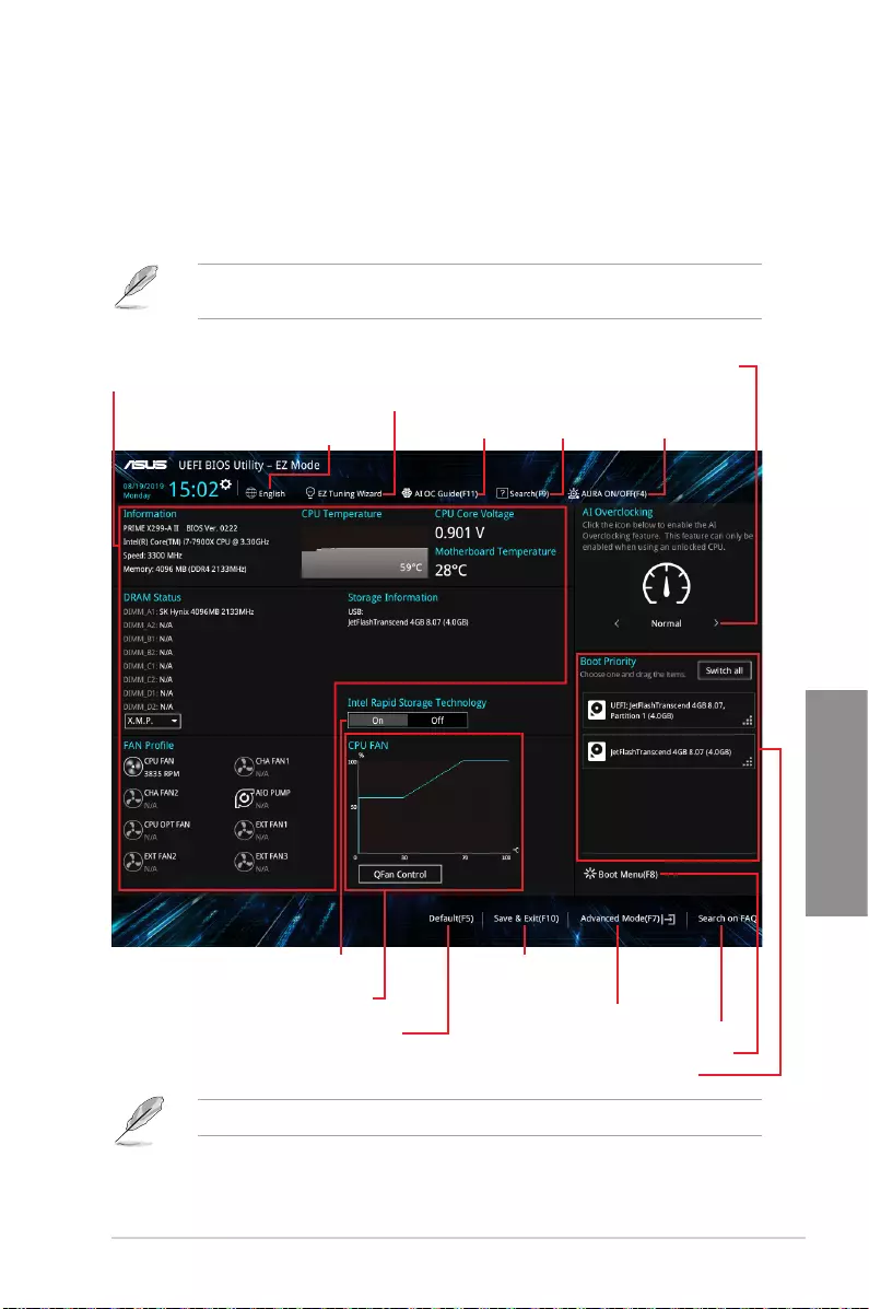
3.2.1 EZ Mode
By default, the EZ Mode screen appears when you enter the BIOS setup program. The EZ
Mode provides you an overview of the basic system information, and allows you to select
the display language, system performance, mode and boot device priority. To access the
Advanced Mode, select Advanced Mode or press the <F7> hotkey for the advanced BIOS
settings.
The default screen for entering the BIOS setup program can be changed. Refer to the
Setup Mode item in section Boot menu for details.
The boot device options vary depending on the devices you installed to the system.
Enables or disables the SATA RAID mode
for Intel Rapid Storage Technology
Selects the display language
of the BIOS setup program
Displays a quick overview
of the system status
Displays the system properties of the selected mode.
Click < or > to switch modes
Loads optimized
default settings
EZ Tuning Wizard
Displays the CPU Fan’s speed. Click
the button to manually tune the fans
Saves the changes
and resets the system
Click to display boot devices
Selects the boot device priority
Click to go to Advanced Mode
Search on the FAQ
Search(F9) AURA ON/OFF(F4)AI OC Guide(F11)
3-4 Chapter 3: BIOS Setup
Chapter 3
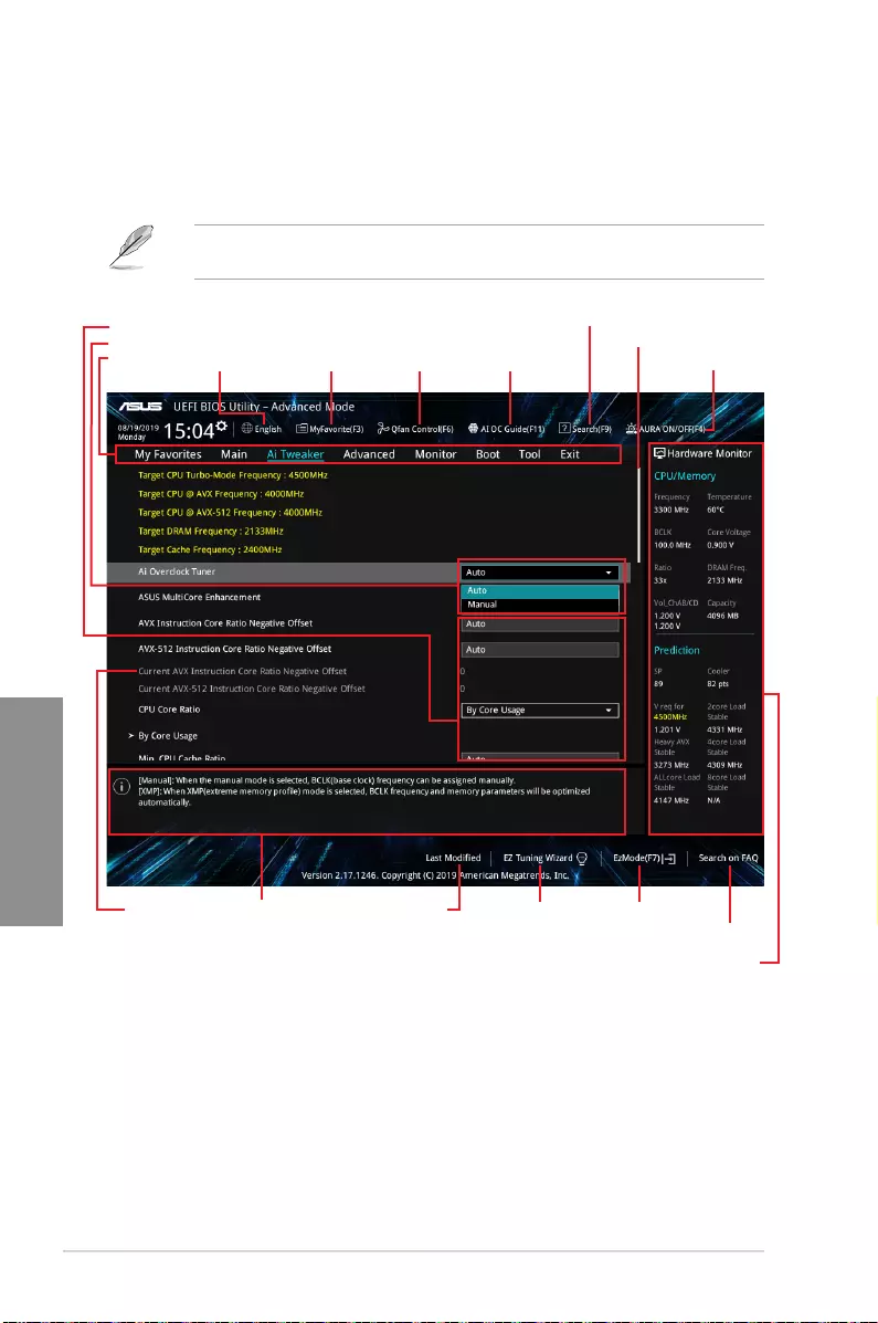
3.2.2 Advanced Mode
The Advanced Mode provides advanced options for experienced end-users to congure
the BIOS settings. The gure below shows an example of the Advanced Mode. Refer to the
following sections for the detailed congurations.
To switch from EZ Mode to Advanced Mode, click Advanced Mode(F7) or press the <F7>
hotkey.
Menu items General help
Menu bar Language Qfan Control(F6)MyFavorite(F3) AI OC Guide(F11) AURA ON/OFF(F4)
Search(F9)
Scroll bar
Pop-up Menu
Configuration fields
Last modified settings EZ Tuning Wizard
Displays a quick overview
of the system status
Search on the FAQ
Go back to EZ Mode

ASUS PRIME X299-A II 3-5
Chapter 3
Menu items
The highlighted item on the menu bar displays the specic items for that menu. For example,
selecting Main shows the Main menu items.
The other items (My Favorites, Ai Tweaker, Advanced, Monitor, Boot, Tool, and Exit) on the
menu bar have their respective menu items.
Submenu items
A greater than sign (>) before each item on any menu screen means that the item has a
submenu. To display the submenu, select the item and press <Enter>.
Language
This button above the menu bar contains the languages that you can select for your BIOS.
Click this button to select the language that you want to display in your BIOS screen.
My Favorites(F3)
This button above the menu bar shows all BIOS items in a Tree Map setup. Select frequently-
used BIOS settings and save it to MyFavorites menu.
Refer to section My Favorites for more information.
Q-Fan Control(F6)
This button above the menu bar displays the current settings of your fans. Use this button to
manually tweak the fans to your desired settings.
Refer to section Q-Fan Control for more information.
AI OC Guide(F11)
This button above the menu bar allows you to view the descriptions of AI overclocking and
enable it.
• Refer to section AI OC Guide for more information.
• This function is only enabled when using an unlocked CPU.
Menu bar
The menu bar on top of the screen has the following main items:
My Favorites For saving the frequently-used system settings and conguration.
Main For changing the basic system conguration
Ai Tweaker For changing the overclocking settings
Advanced For changing the advanced system settings
Monitor For displaying the system temperature, power status, and changing
the fan settings.
Boot For changing the system boot conguration
Tool For conguring options for special functions
Exit For selecting the exit options and loading default settings
3-6 Chapter 3: BIOS Setup
Chapter 3
Search (F9)
This button allows you to search for BIOS items by entering its name, enter the item name to
nd the related item listing.
AURA (F4)
This button allows you to turn the RGB LED lighting or functional LED on or off.
[All On]: All LEDs (Aura or Functional) will be enabled.
[Aura Only]: Aura LEDs will be enabled and functional LEDs will be disabled.
[Aura Off]: Aura LEDs will be disabled, however functional LEDs will still be enabled.
[Stealth Mode]: All LEDs (Aura and Functional) will be disabled.
Search on FAQ
Move your mouse over this button to show a QR code, scan this QR code on your mobile
device to connect to the BIOS FAQ web page of the ASUS support website. You can also
scan the following QR code:
Scroll bar
A scroll bar appears on the right side of a menu screen when there are items that do not t
on the screen. Press the Up/Down arrow keys or <Page Up> / <Page Down> keys to display
the other items on the screen.
General help
At the bottom of the menu screen is a brief description of the selected item. Use <F12> key
to capture the BIOS screen and save it to the removable storage device.
Configuration fields
These elds show the values for the menu items. If an item is user-congurable, you can
change the value of the eld opposite the item. You cannot select an item that is not user-
congurable.
A congurable eld is highlighted when selected. To change the value of a eld, select it and
press <Enter> to display a list of options.
Hot keys
This button contains the navigation keys for the BIOS setup program. Use the navigation
keys to select items in the menu and change the settings.

ASUS PRIME X299-A II 3-7
Chapter 3
EZ Tuning Wizard
This button allows you to view and congure the RAID settings of your system.
Refer to section EZ Tuning Wizard for more information.
Last Modified button
This button shows the items that you last modied and saved in BIOS Setup.
3-8 Chapter 3: BIOS Setup
Chapter 3
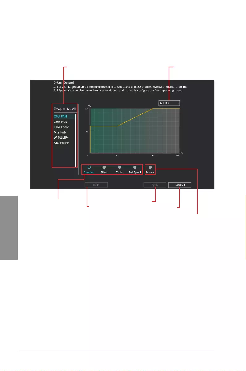
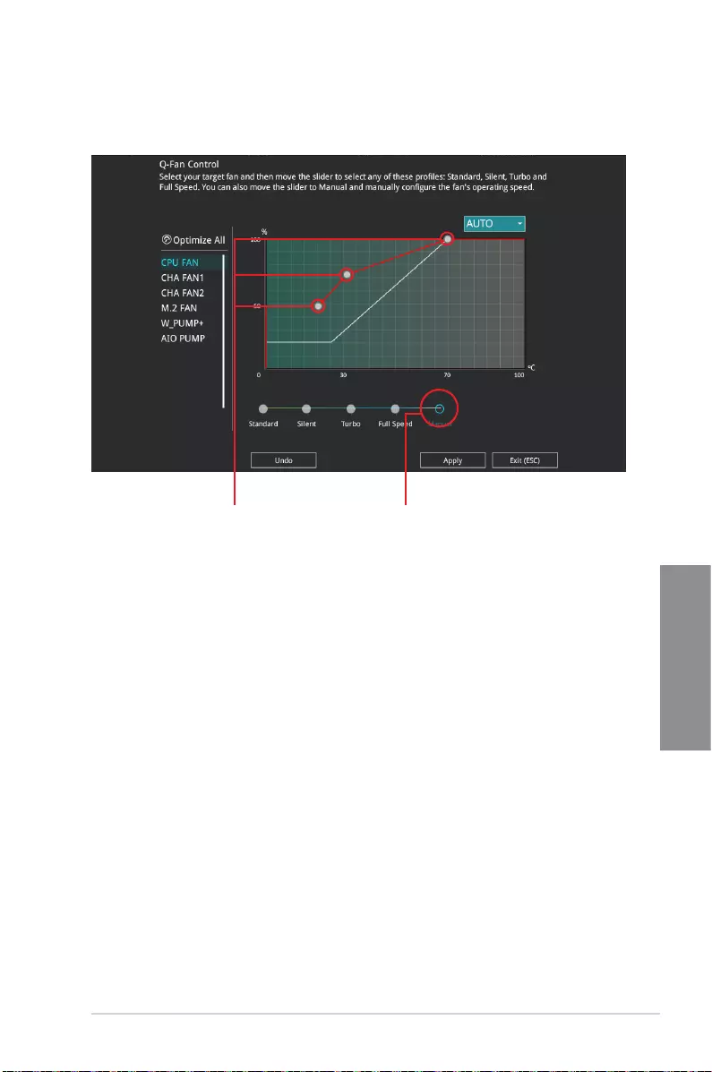
3.2.3 Q-Fan Control
The Q-Fan Control allows you to set a fan prole or manually congure the operating speed
of your CPU and chassis fans.
Click to select a fan to
be configured
Click to undo the
changes
Click to apply the fan setting
Click to go back to main menu
Select a profile to apply to
your fans
Select between
different Q-Fan modes
Select to manually configure
your fans
ASUS PRIME X299-A II 3-9
Chapter 3
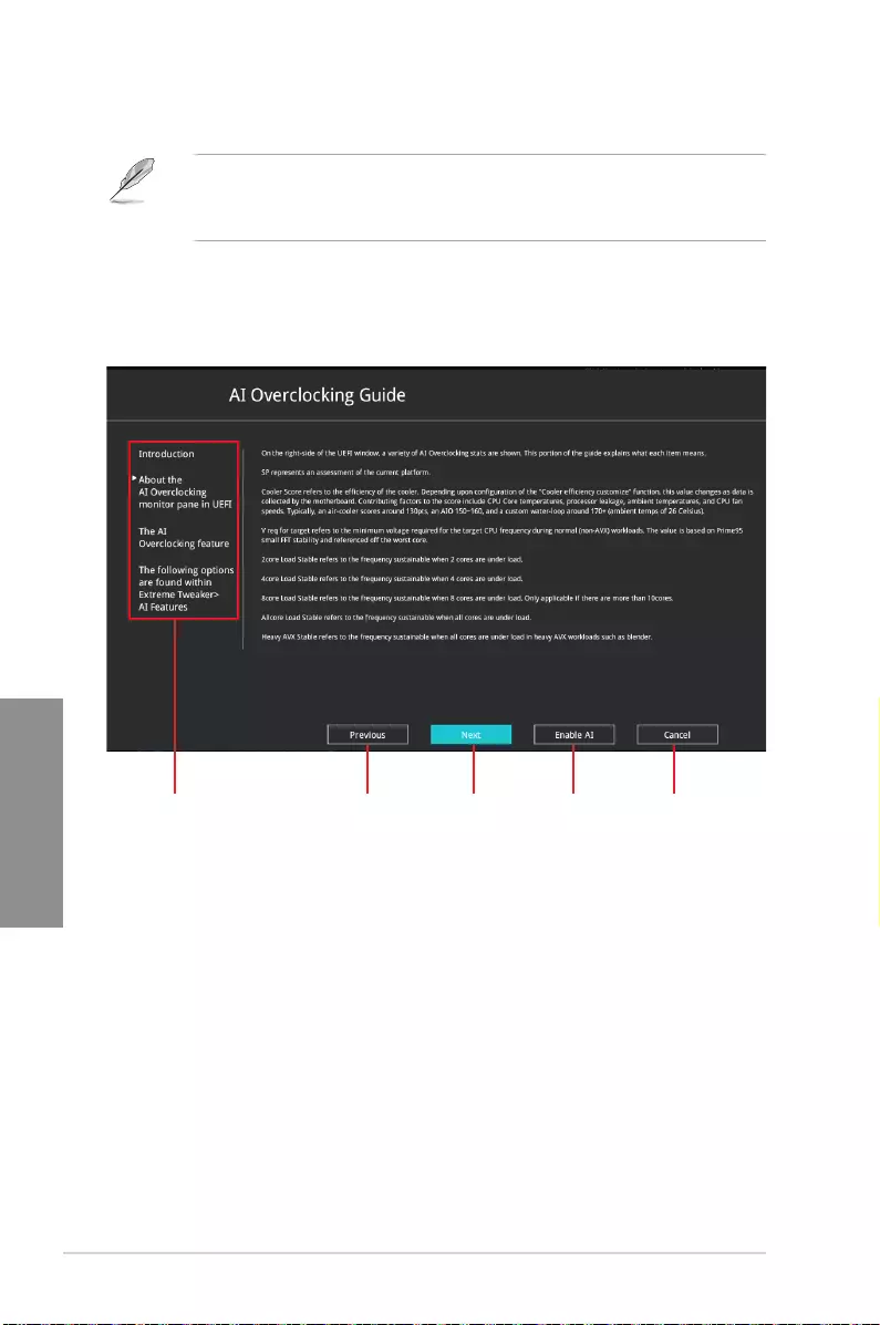
Speed points Select to manually
configure your fans
Configuring fans manually
Select Manual from the list of proles to manually congure your fans’ operating speed.
To congure your fans:
1. Select the fan that you want to congure and to view its current status.
2. Click and drag the speed points to adjust the fans’ operating speed.
3. Click Apply to save the changes then click Exit (ESC).
3-10 Chapter 3: BIOS Setup
Chapter 3
3.2.4 AI OC Guide
• The screenshot shown in this section is for reference purposes only, and may not
exactly match what you see on your screen.
• This function is only enabled when using an unlocked CPU.
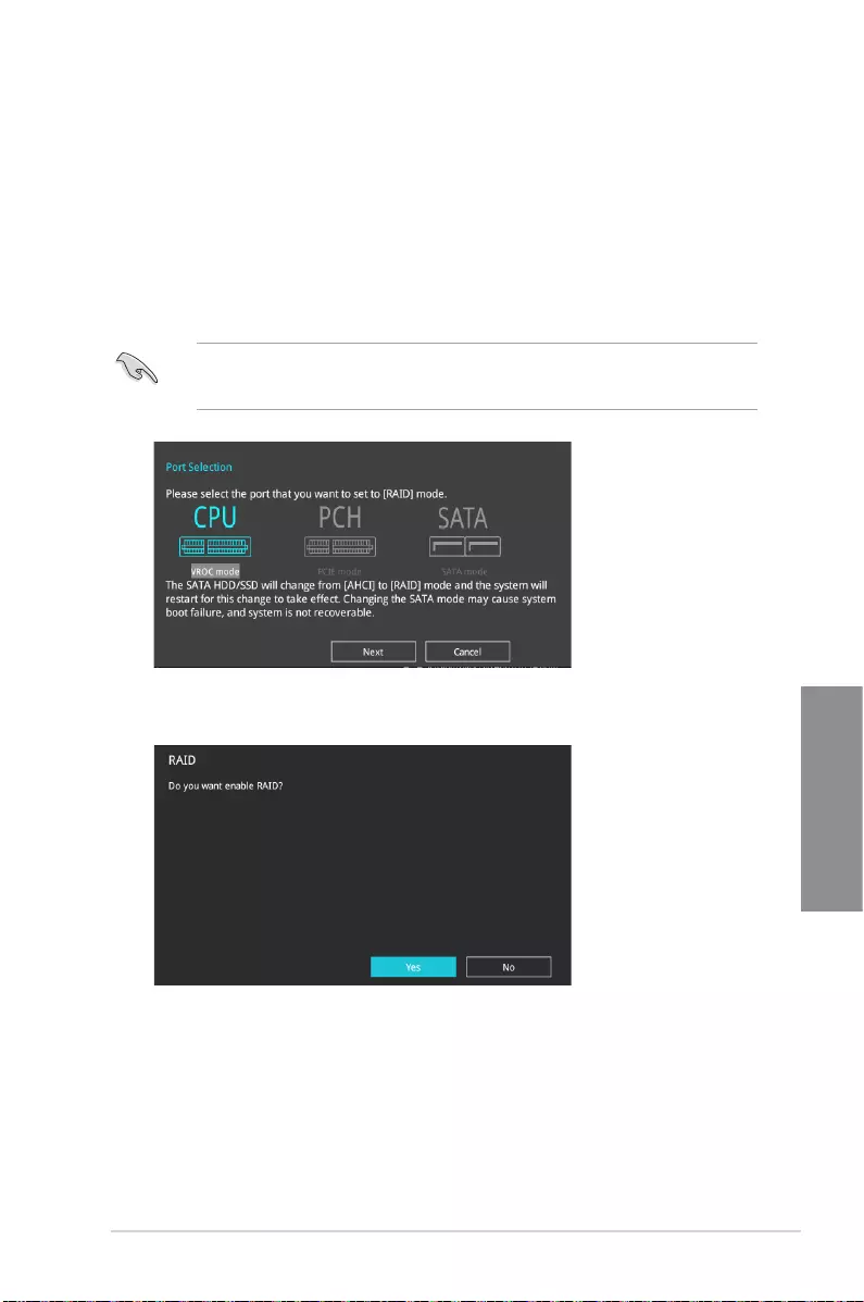
The AI OC Guide allows you to enable the Ai Overclocking feature, or view a quick guide
of the Ai Overclocking feature which highlights the recommended setup procedure and
descriptions of the AI Overclocking.
Clicking on Enable AI will enable AI Overclocking.
Click to view
the next topic in
the quick guide
Click to view the
previous topic in
the quick guide
Quick guide topics Click to go back
to main menu
Click to enable
AI Overclocking
ASUS PRIME X299-A II 3-11
Chapter 3
3.2.5 EZ Tuning Wizard
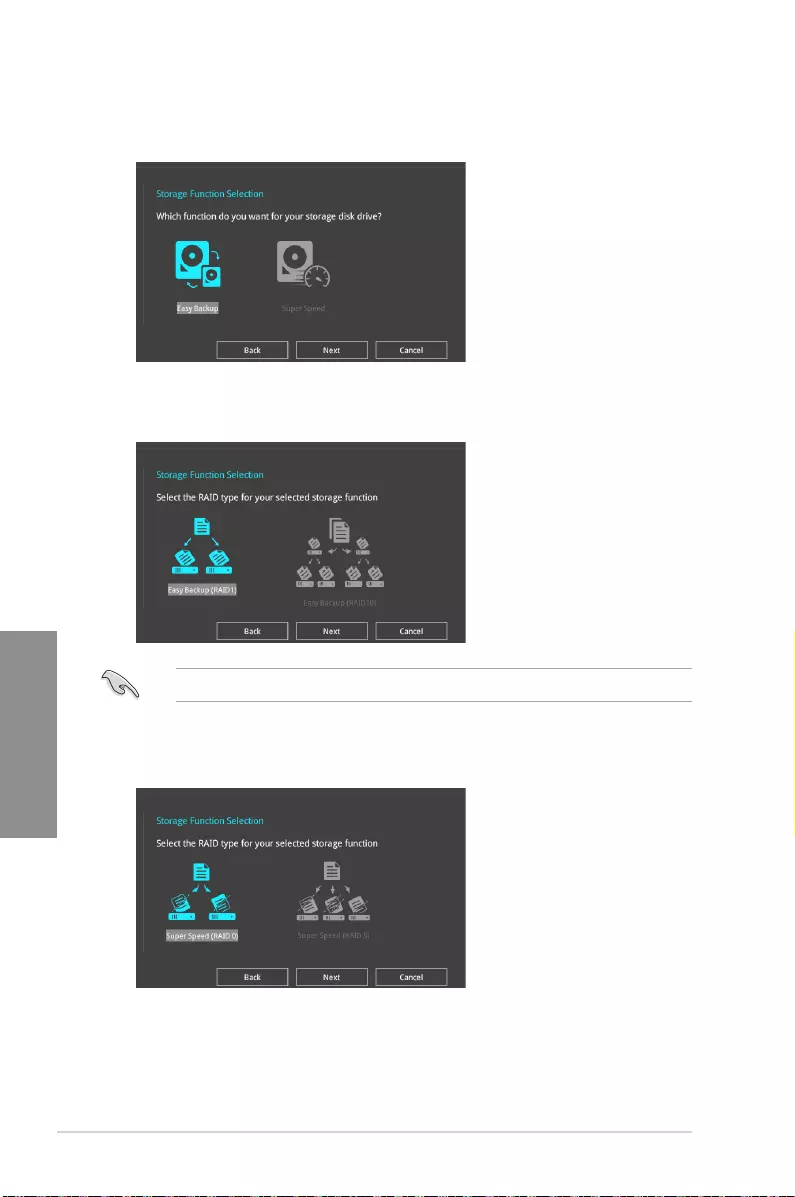
EZ Tuning Wizard allows you to easily set RAID in your system using this feature.
Creating RAID
To create RAID:
1. Click EZ Tuning Wizard from the BIOS screen to open EZ Tuning Wizard screen.
2. Click RAID
then select the port that you want to set to [RAID] mode, CPU, PCH or
SATA, then click Next.
• Ensure that your HDDs have no existing RAID volumes.
• Ensure to connect your HDDs to Intel® SATA connectors.
3. Select Yes to enable RAID.
3-12 Chapter 3: BIOS Setup
Chapter 3
5. After selecting the type of RAID, click Next then click Yes to continue the RAID setup.
6. After the RAID setup is done, click Yes to exit the setup then click OK to reset your
system.
You can only select Easy Backup (RAID 10) if you connect four (4) HDDs.
b. For Super Speed, click Next then select from Super Speed (RAID 0) or Super
Speed (RAID 5).
a. For Easy Backup, click Next then select from Easy Backup (RAID 1) or Easy
Backup (RAID 10).
4. Select the type of storage for your RAID, Easy Backup or Super Speed, then click
Next.
ASUS PRIME X299-A II 3-13
Chapter 3
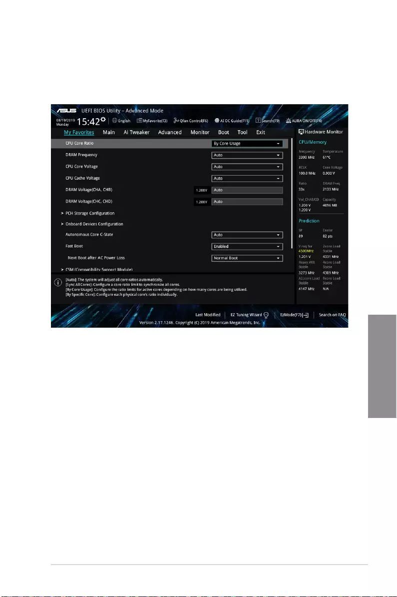
3.3 My Favorites
My Favorites is your personal space where you can easily save and access your favorite
BIOS items. My Favorites comes with several performance, power saving, and fast boot
related items by default. You can personalize this screen by adding or removing items.
3-14 Chapter 3: BIOS Setup
Chapter 3
Adding items to My Favorites
To add BIOS items:
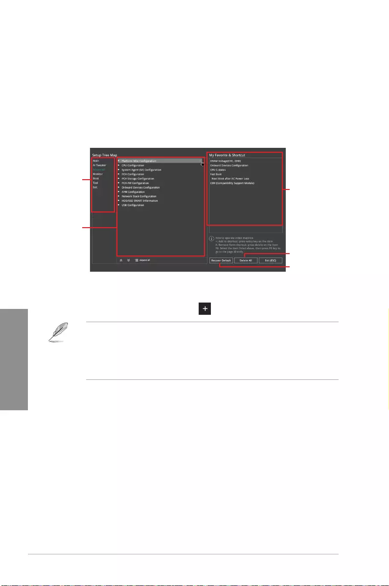
1. Press <F3> on your keyboard or click MyFavorite(F3) from the BIOS screen to open
Setup Tree Map screen.
2. On the Setup Tree Map screen, select the BIOS items that you want to save in My
Favorites screen.
3. Select an item from main menu panel, then click the submenu that you want to save as
favorite from the submenu panel and click or press <Enter> on your keyboard.
You cannot add the following items to My Favorite items:
• Items with submenu options
• User-managed items such as language and boot order
• Conguration items such as Memory SPD Information, system time and date.
4. Click Exit (ESC) or press <Esc> key to close Setup Tree Map screen.
5. Go to My Favorites menu to view the saved BIOS items.
Main menu panel
Submenu panel
Selected shortcut
items
Delete all favorite
items
Recover to default
favorite items

ASUS PRIME X299-A II 3-15
Chapter 3
3.4 Main menu
The Main menu screen appears when you enter the Advanced Mode of the BIOS Setup
program. The Main menu provides you an overview of the basic system information, and
allows you to set the system date, time, language, and security settings.
Security
The Security menu items allow you to change the system security settings.
• If you have forgotten your BIOS password, erase the CMOS Real Time Clock (RTC)
RAM to clear the BIOS password. See section Onboard jumpers for information on
how to erase the RTC RAM via the Clear CMOS button.
• The Administrator or User Password items on top of the screen show the default [Not
Installed]. After you set a password, these items show [Installed].
3.5 Ai Tweaker menu
The Ai Tweaker menu items allow you to congure overclocking-related items.
Be cautious when changing the settings of the Ai Tweaker menu items. Incorrect eld
values can cause the system to malfunction.
The conguration options for this section vary depending on the CPU and DIMM model you
installed on the motherboard.
Ai Overclock Tuner
Allows you to select the CPU overclocking options to achieve the desired CPU internal
frequency. Conguration options:
[Auto] Loads the optimal settings for the system.
[Manual] Allows you to individually set overclocking parameters.
[X.M.P.] If you install memory modules supporting the eXtreme Memory Prole
(X.M.P.) Technology, choose this item to set the proles supported by your
memory modules for optimizing the system performance.
The [X.M.P.] conguration option appears only when you install memory modules
supporting the eXtreme Memory Prole(X.M.P.) Technology.
The following item appears only when you set the Ai Overclocking Tuner to [Manual].
BCLK Frequency
This item allows you to set the BCLK (base clock) frequency to enhance the system
performance. Use the <+> or <-> to adjust the value.
We recommend you to set the value based on the CPU specication, as high BCLK
frequencies may damage the CPU permanently.

3-16 Chapter 3: BIOS Setup
Chapter 3
ASUS MultiCore Enhancement
[Auto] This item allows you to maximize the oveclocking performance optimized
by ASUS core ratio settings.
[Disabled] This item allows you to set to default core ratio settings.
CPU Core Ratio
This item allows you to set the CPU core ratios.
Conguration options: [Auto] [Sync All Cores] [By Core Usage] [By Specic Core]
[AI Optimized]
BCLK Frequency : DRAM Frequency Ratio
[Auto] The BCLK frequency to DRAM frequency ratio will be set to the optimized
setting.
[100:133] The BCLK frequency to DRAM frequency ratio will be set to 100:133.
[100:100] The BCLK frequency to DRAM frequency ratio will be set to 100:100.
DRAM Frequency
This item allows you to set the memory operating frequency. The congurable options vary
with the BCLK (base clock) frequency setting. Select the auto mode to apply the optimized
setting.
If you are using a DIMM with a higher supported frequency than the CPU BCLK frequency,
please enter BIOS and go to Ai Tweaker > DRAM Frequency and set it to the memory
frequency of your DIMM. Please refer to BIOS Setup section for more information on
navigation BIOS.
Internal CPU Power Management
The subitems in this menu allow you to set the CPU ratio and features.
Enhanced Intel SpeedStep Technology
Allows the operating system to dynamically adjust the processor voltage and cores
frequency to decrease the average power consumption and decrease average heat
production.
Conguration options: [Enabled] [Disabled]
Turbo Mode
Allows you to enable your processor cores to run faster than the base operating
frequency when it is below power, current and specication limit. Conguration options:
[Disabled] [Enabled]

ASUS PRIME X299-A II 3-17
Chapter 3
3.6.3 System Agent (SA) Configuration
The items in this menu allow you to adjust the Link Speed for PEG Port and Multi-Monitor.
3.6.1 CPU Configuration
The items in this menu show the CPU-related information that the BIOS automatically
detects.
The items in this menu may vary based on the CPU installed.
Hyper-Threading [ALL]
This item allows a hyper-threading processor to appear as two logical processors, allowing
the operating system to schedule two threads or processors simultaneously.
Conguration options: [Disabled] [Enabled]
CPU Power Management Configuration
This item allows you to manage and congure the CPU’s power.
Enhanced Intel SpeedStep Technology
This item allows more than two frequency to be supported.
Conguration options: [Enabled] [Disabled]
Turbo Mode
This item allows you to automatically set the CPU cores to run faster than the base
operating frequency when it is below the operating power, current and temperature
specication limit.
Conguration options: [Enabled] [Disabled]
Autonomous Core C-State
This item allows you to set the power saving of the CPU states.
Conguration options: [Auto] [Disabled] [Enabled]
3.6 Advanced menu
The Advanced menu items allow you to change the settings for the CPU and other system
devices.
Be cautious when changing the settings of the Advanced menu items. Incorrect eld values
can cause the system to malfunction.
3.6.2 Platform Misc Configuration
The items in this menu allow you to change the ASPM for PCH and SA PCIe.

3-18 Chapter 3: BIOS Setup
Chapter 3
3.6.4 PCH Configuration
The items in this menu allow you to adjust the PCH PCIe speed.
PCI Express Configuration
This item allows you to congure the PCIe slots.
PCIe Speed
This item allows your system to automatically select the PCIe port speed.
Conguration options: [Auto] [Gen 1 (2.5 GT/s)] [Gen 2 (5 GT/s)] [Gen 3 (8 GT/s)]
3.6.5 PCH Storage Configuration
While entering Setup, the BIOS automatically detects the presence of SATA devices. The
SATA Port items show Not Present if no SATA device is installed to the corresponding SATA
port.
SATA Controller(s)
This item allows you to enable or disable the SATA Device.
Conguration options: [Disabled] [Enabled]
SATA Mode Selection
This item allows you to set the SATA conguration.
[AHCI] Set to [AHCI] when you want the SATA hard disk drives to
use the AHCI (Advanced Host Controller Interface). The
AHCI allows the onboard storage driver to enable advanced
Serial ATA features that increases storage performance on
random workloads by allowing the drive to internally optimize
the order of commands.
[Intel RST Premium
(RAID)]
Set to [Intel RST Premium (RAID)] when you want to create a
RAID conguration from the SATA hard disk drives.
SMART Status Check
SMART (Self-Monitoring, Analysis and Reporting Technology) is a monitoring system that
shows a warning message during POST (Power-on Self Test) when an error occurs in the
hard disks.
Conguration options: [On] [Off]
SATA6G_1 — SATA6G_8
SATA6G_1 — SATA6G_8
This item allows you to enable or disable the selected SATA port.
Conguration options: [Disabled] [Enabled]
Hot Plug
These items appears only when the SATA Mode Selection is set to [AHCI] and allows
you to enable or disable SATA Hot Plug Support.
Conguration options: [Disabled] [Enabled]

ASUS PRIME X299-A II 3-19
Chapter 3
HD Audio Controller
This item allows you to use the Azalia High Denition Audio Controller.
Conguration options: [Disabled] [Enabled]
RGB LED lighting
When system is in working state
This item allows you to turn the RGB LED lighting on or off when the system is in the
working state.
Conguration options: [On] [Off]
When system is in sleep, hibernate or soft off states
This item allows you to turn the RGB LED lighting on or off when the system is in the
sleep, hibernate or soft off states.
Conguration options: [On] [Off]
Intel LAN Controller
This item allows you to enable or disable the Intel LAN controller.
Conguration options: [Disabled] [Enabled]
3.6.7 Onboard Devices Configuration
The items in this menu allow you to switch between PCIe Lanes and congure onboard
devices.
3.6.6 CPU Storage Configuration
The items in this menu allow you to congure CPU storage congurations.

3-20 Chapter 3: BIOS Setup
Chapter 3
3.6.8 APM Configuration
The items in this menu allow you to set system wake and sleep settings.
ErP Ready [Disabled]
This item allows you to switch off some power at S4+S5 or S5 to get the system ready for
ErP requirement. When set to [Enabled], all other PME options are switched off.
Conguration options: [Disabled] [Enable(S4+S5)] [Enable(S5)]
3.6.9 Network Stack Configuration
The items in this menu allow you to congure Ipv4 / Ipv6 PXE support.
3.6.10 HDD/SSD SMART Information
This menu displays the SMART information of the connected devices.
NVM Express devices do not support SMART information.
3.6.11 USB Configuration
The items in this menu allow you to change the USB-related features.
The Mass Storage Devices item shows the auto-detected values. If no USB device is
detected, the item shows None.
USB Single Port Control
This item allows you to enable or disable the individual USB ports.
Refer to section Motherboard layout for the location of the USB ports.

ASUS PRIME X299-A II 3-21
Chapter 3
3.7 Monitor menu
The Monitor menu displays the system temperature/power status, and allows you to change
the fan settings.
Q-Fan Configuration
Q-Fan Tuning
Click this item to automatically detect the lowest speed and congure the minimum
duty cycle for each fan.
AIO PUMP/W_PUMP+ Control
[Disabled] Disable the Water Pump control feature.
[Auto] Detects the type of water pump installed and automatically switches
the control modes.
[DC mode] Enable the Water Pump control in DC mode for 3-pin chassis fan.
[PWM mode] Enable the Water Pump control in PWM mode for 4-pin chassis fan.
3.8 Boot menu
The Boot menu items allow you to change the system boot options.
Fast Boot
[Disabled] Allows your system to go back to its normal boot speed.
[Enabled] Allows your system to accelerate the boot speed.
The following items appear only when you set the Fast Boot to [Enabled].
Next Boot after AC Power Loss
[Normal Boot] Returns to normal boot on the next boot after an AC power loss.
[Fast Boot] Accelerates the boot speed on the next boot after an AC power loss.
3.6.12 Thunderbolt(TM) Configuration
The items in this menu allow you to congure Thunderbolt settings.
TBT Root port Selector
This item allows you to select the thunder root port.
Conguration options: [Thunderbolt Disabled] [PCIEX16_1] [PCIEX16_2] [PCIEX16_3]
3.6.13 PCH-FW Configuration
This item allows you to congure the rmware TPM.

3-22 Chapter 3: BIOS Setup
Chapter 3
Boot Configuration
Setup Mode
[Advanced Mode] This item allows you to go to Advanced Mode of the BIOS after
POST.
[EZ Mode] This item allows you to go to EZ Mode of the BIOS after POST.
CSM (Compatibility Support Module)
This item allows you to congure the CSM (Compatibility Support Module) items to fully
support the various VGA, bootable devices and add-on devices for better compatibility.
Launch CSM
[Auto] The system automatically detects the bootable devices and the add-
on devices.
[Enabled] For better compatibility, enable the CSM to fully support the non-UEFI
driver add-on devices or the Windows® UEFI mode.
[Disabled] Disable the CSM to fully support the non-UEFI driver add-on devices
or the Windows® UEFI mode.
The following items appear only when you set the Launch CSM to [Enabled].
Boot Devices Control
This item allows you to select the type of devices that you want to boot.
Conguration options: [UEFI and Legacy OPROM] [Legacy OPROM only]
[UEFI only]
Boot from Network Devices
This item allows you to select the type of network devices that you want to
launch.
Conguration options: [Ignore] [Legacy only] [UEFI driver rst]
Boot from Storage Devices
This item allows you to select the type of storage devices that you want to
launch.
Conguration options: [Ignore] [Legacy only] [UEFI driver rst]
Boot from PCI-E/PCI Expansion Devices
This item allows you to select the type of PCIe/PCI expansion devices that
you want to launch.
Conguration options: [Legacy only] [UEFI driver rst]
Secure Boot
This item allows you to congure the Windows® Secure Boot settings and manage its keys to
protect the system from unauthorized access and malwares during POST.

ASUS PRIME X299-A II 3-23
Chapter 3
Boot Option Priorities
These items specify the boot device priority sequence from the available devices. The
number of device items that appears on the screen depends on the number of devices
installed in the system.
• To access Windows® OS in Safe Mode, press <F8> after POST (Windows® 8 not
supported).
• To select the boot device during system startup, press <F8> when the ASUS Logo
appears.
Boot Override
These items displays the available devices. The number of device items that appears on
the screen depends on the number of devices installed in the system. Click an item to start
booting from the selected device.
3.9 Tool menu
The Tool menu items allow you to congure options for special functions. Select an item then
press <Enter> to display the submenu.
3.9.1 ASUS EZ Flash 3 Utility
This item allows you to run ASUS EZ Flash 3. When you press <Enter>, a conrmation
message appears. Use the left/right arrow key to select between [Yes] or [No], then press
<Enter> to conrm your choice.
For more details, refer to section ASUS EZ Flash 3.
Setup Animator
This item allows you to enable or disable the Setup animator.
Conguration options: [Disabled] [Enabled]
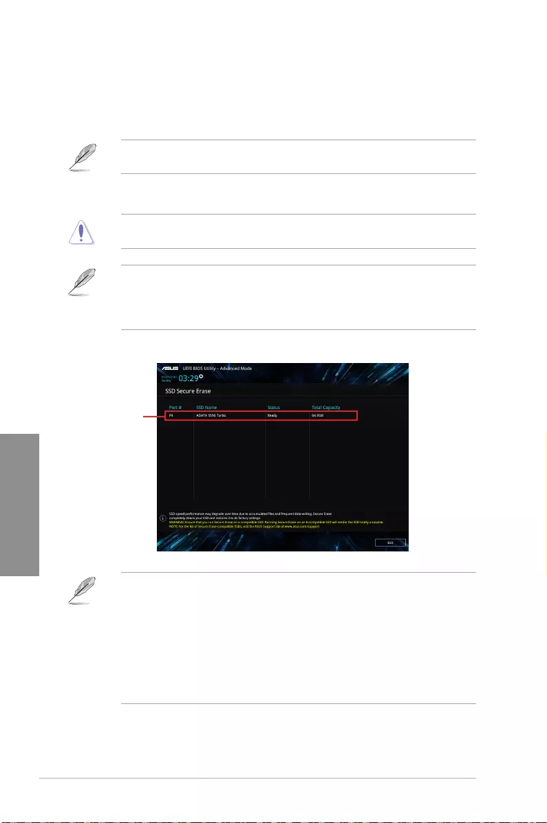
3-24 Chapter 3: BIOS Setup
Chapter 3
3.9.2 Secure Erase
SSD speeds may lower over time as with any storage medium due to data processing.
Secure Erase completely and safely cleans your SSD, restoring it to factory performance
levels.
Secure Erase is only available in AHCI mode. Ensure to set the SATA mode to AHCI. Click
Advanced > PCH Storage Configuration > SATA Mode Selection > AHCI.
To launch Secure Erase, click Tool > Secure Erase on the Advanced mode menu.
Check the ASUS support site for a full list of SSDs tested with Secure Erase. The drive may
become unstable if you run Secure Erase on an incompatible SSD.
• The time to erase the contents of your SSD may take a while depending on its size.
Do not turn off the system during the process.
• Secure Erase is only supported on Intel SATA port. For more information about Intel
SATA ports, refer to section Motherboard layout of this manual.
Status definition:
• Frozen. The frozen state is the result of a BIOS protective measure. The BIOS guards
drives that do not have password protection by freezing them prior to booting. If the
drive is frozen, a power off or hard reset of your PC must be performed to proceed
with the Secure Erase.
• Locked. SSDs might be locked if the Secure Erase process is either incomplete or
was stopped. This may be due to a third party software that uses a different password
dened by ASUS. You have to unlock the SSD in the software before proceeding with
Secure Erase.
Displays the
available SSDs

ASUS PRIME X299-A II 3-25
Chapter 3
3.9.3 ASUS User Profile
This item allows you to save and load BIOS setting proles.
Load from Profile
This item allows you to load the previous BIOS settings saved in the BIOS Flash. Key in the
prole number that saved your BIOS settings, press <Enter>, and then select Yes.
• DO NOT shut down or reset the system while updating the BIOS to prevent the
system boot failure!
• We recommend that you update the BIOS le only coming from the same memory/
CPU conguration and BIOS version.
Profile Name
This item allows you to key in a prole name.
Save to Profile
This item allows you to save the current BIOS settings to the BIOS Flash, and create a
prole. Key in a prole number from one to eight, press <Enter>, and then select Yes.
Load/Save Profile from/to USB Drive
This item allows you to load or save prole from your USB drive, load and save prole to your
USB drive.
3.9.4 ASUS SPD Information
This item allows you to view the DRAM SPD information.
3.9.5 Graphics Card Information
This item displays the information about the graphics card installed in your system.
GPU Post
This item displays the information and recommended conguration for the PCIe slots that the
graphics card is installed in your system.
This feature is only supported on selected ASUS graphics cards.
Bus Interface
This item allows you to select the bus interface.
Conguration options: [PCIEX16_1]

3-26 Chapter 3: BIOS Setup
Chapter 3
3.10 Exit menu
The Exit menu items allow you to load the optimal default values for the BIOS items, and
save or discard your changes to the BIOS items. You can access the EZ Mode from the Exit
menu.
Load Optimized Defaults
This option allows you to load the default values for each of the parameters on the Setup
menus. When you select this option or if you press <F5>, a conrmation window appears.
Select OK to load the default values.
Save Changes & Reset
Once you are nished making your selections, choose this option from the Exit menu to
ensure the values you selected are saved. When you select this option or if you press <F10>,
a conrmation window appears. Select OK to save changes and exit.
Discard Changes & Exit
This option allows you to exit the Setup program without saving your changes. When you
select this option or if you press <Esc>, a conrmation window appears. Select Yes to
discard changes and exit.
Launch EFI Shell from USB drives
This item allows you to attempt to launch the EFI Shell application (shellx64.e) from one of
the available lesystem devices.

ASUS PRIME X299-A II 3-27
Chapter 3
3.11 Updating BIOS
The ASUS website publishes the latest BIOS versions to provide enhancements on system
stability, compatibility,and performance. However, BIOS updating is potentially risky. If
there is no problem using the current version of BIOS, DO NOT manually update the BIOS.
Inappropriate BIOS updating may result to system’s failure to boot. Carefully follow the
instructions in this chapter to update your BIOS when necessary.
Visit http://www.asus.com to download the latest BIOS le for this motherboard.
The following utilities allow you to manage and update the motherboard BIOS setup program.
1. EZ Update: Updates the BIOS in Windows® environment.
2. ASUS EZ Flash 3: Updates the BIOS using a USB ash drive.
3. ASUS CrashFree BIOS 3: Restores the BIOS using the motherboard support DVD or a
USB ash drive when the BIOS le fails or gets corrupted.
3.11.1 EZ Update
The EZ Update is a utility that allows you to update the motherboard BIOS in Windows®
environment.
• EZ Update requires an Internet connection either through a network or an ISP
(Internet Service Provider).
• This utility is available in the support DVD that comes with the motherboard package.
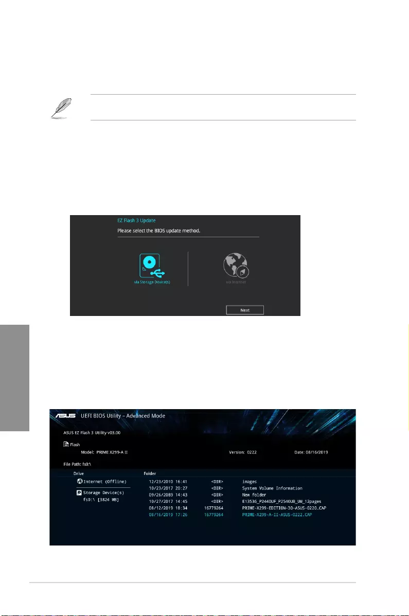
3-28 Chapter 3: BIOS Setup
Chapter 3
3.11.2 ASUS EZ Flash 3
ASUS EZ Flash 3 allows you to download and update to the latest BIOS through the Internet
without having to use a bootable oppy disk or an OS-based utility.
Updating through the Internet varies per region and Internet conditions. Check your local
Internet connection before updating through the Internet.
To update the BIOS by USB:
1. Enter the Advanced Mode of the BIOS setup program. Go to the Tool menu to select
ASUS EZ Flash 3 Utility and press <Enter>.
2. Insert the USB ash disk that contains the latest BIOS le to the USB port.
3. Select via Storage Device(s).
4. Press <Tab> to switch to the Drive eld.
5. Press the Up/Down arrow keys to nd the USB ash disk that contains the latest BIOS,
and then press <Enter>.
6. Press <Tab> to switch to the Folder Info eld.
7. Press the Up/Down arrow keys to nd the BIOS le, and then press <Enter> to perform
the BIOS update process. Reboot the system when the update process is done.
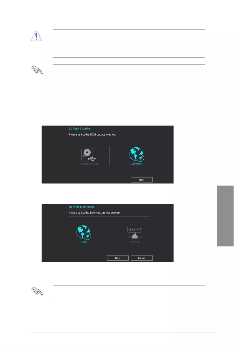
ASUS PRIME X299-A II 3-29
Chapter 3
• This function can support devices such as a USB ash disk with FAT 32/16 format and
single partition only.
• DO NOT shut down or reset the system while updating the BIOS to prevent system
boot failure!
Ensure to load the BIOS default settings to ensure system compatibility and stability. Select
the Load Optimized Defaults item under the Exit menu. See section Exit menu for details.
To update the BIOS by Internet:
1. Enter the Advanced Mode of the BIOS setup program. Go to the Tool menu to select
ASUS EZ Flash 3 Utility and press <Enter>.
2. Select via Internet.
3. Press the Left/Right arrow keys to select an Internet connection method, and then
press <Enter>.
Ensure to load the BIOS default settings to ensure system compatibility and stability. Select
the Load Optimized Defaults item under the Exit menu. See section Exit menu for details.
4. Follow the onscreen instructions to complete the update.
5. Reboot the system when the update process is done.

3-30 Chapter 3: BIOS Setup
Chapter 3
3.11.3 ASUS CrashFree BIOS 3
The ASUS CrashFree BIOS 3 utility is an auto recovery tool that allows you to restore the
BIOS le when it fails or gets corrupted during the updating process. You can restore a
corrupted BIOS le using the motherboard support DVD or a USB ash drive that contains
the BIOS le.
The BIOS le in the motherboard support DVD may be older than the BIOS le published
on the ASUS ofcial website. If you want to use the newer BIOS le, download the le at
https://www.asus.com/support/ and save it to a USB ash drive.
Recovering the BIOS
To recover the BIOS:
1. Turn on the system.
2. Insert the motherboard support DVD to the optical drive, or the USB ash drive
containing the BIOS le to the USB port.
3. The utility automatically checks the devices for the BIOS le. When found, the utility
reads the BIOS le and enters ASUS EZ Flash 3 automatically.
4. The system requires you to enter BIOS Setup to recover the BIOS setting. To ensure
system compatibility and stability, we recommend that you press <F5> to load default
BIOS values.
DO NOT shut down or reset the system while updating the BIOS! Doing so can cause
system boot failure!

ASUS PRIME X299-A II 4-1
Chapter 4
RAID Support
4
Chapter 4: RAID Support
4.1 RAID configurations
The motherboard supports Intel® Rapid Storage Technology with RAID 0, RAID 1, RAID 5,
and RAID 10 solution.
For more information on conguring your RAID sets, please refer to the RAID
Configuration Guide which you can nd at https://www.asus.com/support.
4.1.1 RAID definitions
RAID 0 (Data striping) optimizes two identical hard disk drives to read and write data in
parallel, interleaved stacks. Two hard disks perform the same work as a single drive but at a
sustained data transfer rate, double that of a single disk alone, thus improving data access
and storage. Use of two new identical hard disk drives is required for this setup.
RAID 1 (Data mirroring) copies and maintains an identical image of data from one drive to
a second drive. If one drive fails, the disk array management software directs all applications
to the surviving drive as it contains a complete copy of the data in the other drive. This RAID
conguration provides data protection and increases fault tolerance to the entire system. Use
two new drives or use an existing drive and a new drive for this setup. The new drive must be
of the same size or larger than the existing drive.
RAID 5 stripes both data and parity information across three or more hard disk drives. Among
the advantages of RAID 5 conguration include better HDD performance, fault tolerance, and
higher storage capacity. The RAID 5 conguration is best suited for transaction processing,
relational database applications, enterprise resource planning, and other business systems.
Use a minimum of three identical hard disk drives for this setup.
RAID 10 is data striping and data mirroring combined without parity (redundancy data) having
to be calculated and written. With the RAID 10 conguration you get all the benets of both
RAID 0 and RAID 1 congurations. Use four new hard disk drives or use an existing drive
and three new drives for this setup.

4-2 Chapter 4: RAID Support
Chapter 4

ASUS PRIME X299-A II A-1
Appendix
Appendix
Appendix
Q-Code table
(continued on the next page)
Code Description
00 Not used
01 Power on. Reset type detection (soft/hard).
02 AP initialization before microcode loading
03 System Agent initialization before microcode loading
04 PCH initialization before microcode loading
06 Microcode loading
07 AP initialization after microcode loading
08 System Agent initialization after microcode loading
09 PCH initialization after microcode loading
0B Cache initialization
0C – 0D Reserved for future AMI SEC error codes
0E Microcode not found
0F Microcode not loaded
10 PEI Core is started
11 – 14 Pre-memory CPU initialization is started
15 – 18 Pre-memory System Agent initialization is started
19 – 1C Pre-memory PCH initialization is started
2B – 2F Memory initialization
30 Reserved for ASL (see ASL Status Codes section below)
31 Memory Installed
32 – 36 CPU post-memory initialization
37 – 3A Post-Memory System Agent initialization is started
3B – 3E Post-Memory PCH initialization is started
4F DXE IPL is started
50 – 53 Memory initialization error. Invalid memory type or incompatible memory
speed
54 Unspecied memory initialization error
55 Memory not installed
56 Invalid CPU type or Speed
57 CPU mismatch
58 CPU self test failed or possible CPU cache error
59 CPU micro-code is not found or micro-code update is failed
5A Internal CPU error
5B Reset PPI is not available
5C – 5F Reserved for future AMI error codes

A-2 Appendix
Appendix
Q-Code table
Code Description
E0 S3 Resume is stared (S3 Resume PPI is called by the DXE IPL)
E1 S3 Boot Script execution
E2 Video repost
E3 OS S3 wake vector call
E4 – E7 Reserved for future AMI progress codes
E8 S3 Resume Failed
E9 S3 Resume PPI not Found
EA S3 Resume Boot Script Error
EB S3 OS Wake Error
EC – EF Reserved for future AMI error codes
F0 Recovery condition triggered by rmware (Auto recovery)
F1 Recovery condition triggered by user (Forced recovery)
F2 Recovery process started
F3 Recovery rmware image is found
F4 Recovery rmware image is loaded
F5 – F7 Reserved for future AMI progress codes
F8 Recovery PPI is not available
F9 Recovery capsule is not found
FA Invalid recovery capsule
FB – FF Reserved for future AMI error codes
60 DXE Core is started
61 NVRAM initialization
62 Installation of the PCH Runtime Services
63 – 67 CPU DXE initialization is started
68 PCI host bridge initialization
69 System Agent DXE initialization is started
6A System Agent DXE SMM initialization is started
6B – 6F System Agent DXE initialization (System Agent module specic)
70 PCH DXE initialization is started
71 PCH DXE SMM initialization is started
72 PCH devices initialization
73 – 77 PCH DXE Initialization (PCH module specic)
78 ACPI module initialization
79 CSM initialization
7A – 7F Reserved for future AMI DXE codes
(continued on the next page)

ASUS PRIME X299-A II A-3
Appendix
Q-Code table
Code Description
90 Boot Device Selection (BDS) phase is started
91 Driver connecting is started
92 PCI Bus initialization is started
93 PCI Bus Hot Plug Controller Initialization
94 PCI Bus Enumeration
95 PCI Bus Request Resources
96 PCI Bus Assign Resources
97 Console Output devices connect
98 Console input devices connect
99 Super IO Initialization
9A USB initialization is started
9B USB Reset
9C USB Detect
9D USB Enable
9E – 9F Reserved for future AMI codes
A0 IDE initialization is started
A1 IDE Reset
A2 IDE Detect
A3 IDE Enable
A4 SCSI initialization is started
A5 SCSI Reset
A6 SCSI Detect
A7 SCSI Enable
A8 Setup Verifying Password
A9 Start of Setup
AA Reserved for ASL (see ASL Status Codes section below)
AB Setup Input Wait
AC Reserved for ASL (see ASL Status Codes section below)
AD Ready To Boot event
AE Legacy Boot event
AF Exit Boot Services event
B0 Runtime Set Virtual Address MAP Begin
B1 Runtime Set Virtual Address MAP End
B2 Legacy Option ROM Initialization
B3 System Reset
(continued on the next page)
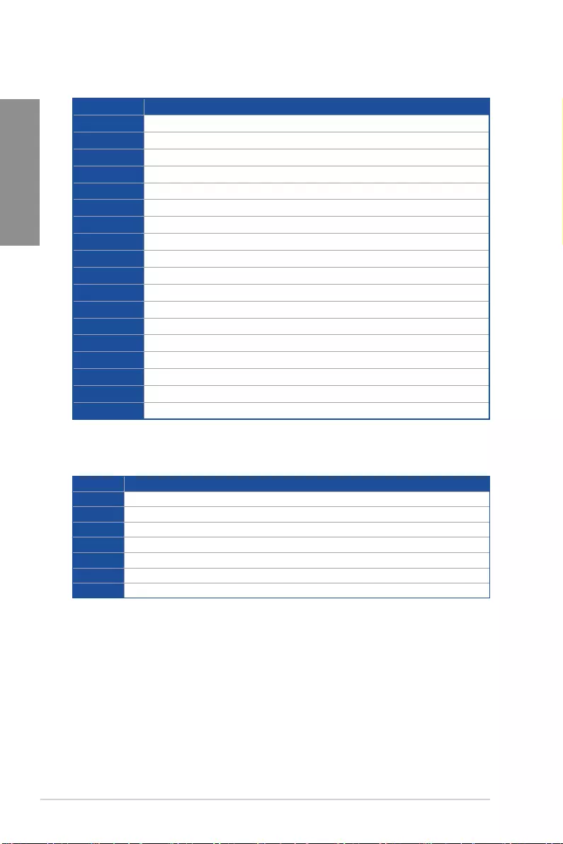
A-4 Appendix
Appendix
Code Description
B4 USB hot plug
B5 PCI bus hot plug
B6 Clean-up of NVRAM
B7 Conguration Reset (reset of NVRAM settings)
B8– BF Reserved for future AMI codes
D0 CPU initialization error
D1 System Agent initialization error
D2 PCH initialization error
D3 Some of the Architectural Protocols are not available
D4 PCI resource allocation error. Out of Resources
D5 No Space for Legacy Option ROM
D6 No Console Output Devices are found
D7 No Console Input Devices are found
D8 Invalid password
D9 Error loading Boot Option (LoadImage returned error)
DA Boot Option is failed (StartImage returned error)
DB Flash update is failed
DC Reset protocol is not available
Q-Code table
ACPI/ASL Checkpoints (under OS)
Code Description
03 System is entering S3 sleep state
04 System is entering S4 sleep state
05 System is entering S5 sleep state
30 System is waking up from the S3 sleep state
40 System is waking up from the S4 sleep state
AC System has transitioned into ACPI mode. Interrupt controller is in PIC mode.
AA System has transitioned into ACPI mode. Interrupt controller is in APIC mode.

ASUS PRIME X299-A II A-5
Appendix
Notices
FCC Compliance Information
Responsible Party: Asus Computer International
Address: 48720 Kato Rd., Fremont, CA 94538, USA
Phone / Fax No: (510)739-3777 / (510)608-4555
This device complies with part 15 of the FCC Rules. Operation is subject to the following
two conditions: (1) This device may not cause harmful interference, and (2) this device must
accept any interference received, including interference that may cause undesired operation.
This equipment has been tested and found to comply with the limits for a Class B digital
device, pursuant to part 15 of the FCC Rules. These limits are designed to provide
reasonable protection against harmful interference in a residential installation. This
equipment generates, uses and can radiate radio frequency energy and, if not installed
and used in accordance with the instructions, may cause harmful interference to radio
communications. However, there is no guarantee that interference will not occur in a
particular installation. If this equipment does cause harmful interference to radio or television
reception, which can be determined by turning the equipment off and on, the user is
encouraged to try to correct the interference by one or more of the following measures:
— Reorient or relocate the receiving antenna.
— Increase the separation between the equipment and receiver.
— Connect the equipment into an outlet on a circuit different from that to which the receiver
is connected.
— Consult the dealer or an experienced radio/TV technician for help.
A-6 Appendix
Appendix
VCCI: Japan Compliance Statement
Class B ITE
KC: Korea Warning Statement
Compliance Statement of Innovation, Science and Economic
Development Canada (ISED)
This device complies with Innovation, Science and Economic Development Canada licence
exempt RSS standard(s). Operation is subject to the following two conditions: (1) this device
may not cause interference, and (2) this device must accept any interference, including
interference that may cause undesired operation of the device.
CAN ICES-3(B)/NMB-3(B)
Déclaration de conformité de Innovation, Sciences et
Développement économique Canada (ISED)
Le présent appareil est conforme aux CNR d’Innovation, Sciences et Développement
économique Canada applicables aux appareils radio exempts de licence. L’exploitation est
autorisée aux deux conditions suivantes: (1) l’appareil ne doit pas produire de brouillage,
et (2) l’utilisateur de l’appareil doit accepter tout brouillage radioélectrique subi, même si le
brouillage est susceptible d’en compromettre le fonctionnement.
CAN ICES-3(B)/NMB-3(B)

ASUS PRIME X299-A II A-7
Appendix
Declaration of compliance for product environmental
regulation
ASUS follows the green design concept to design and manufacture our products, and
makes sure that each stage of the product life cycle of ASUS product is in line with global
environmental regulations. In addition, ASUS disclose the relevant information based on
regulation requirements.
Please refer to http://csr.asus.com/Compliance.htm for information disclosure based on
regulation requirements ASUS is complied with:
EU REACH and Article 33
Complying with the REACH (Registration, Evaluation, Authorisation, and Restriction of
Chemicals) regulatory framework, we published the chemical substances in our products at
ASUS REACH website at http://csr.asus.com/english/REACH.htm.
EU RoHS
This product complies with the EU RoHS Directive. For more details, see
http://csr.asus.com/english/article.aspx?id=35
India RoHS
This product complies with the “India E-Waste (Management) Rules, 2016” and prohibits
use of lead, mercury, hexavalent chromium, polybrominated biphenyls (PBBs) and
polybrominated diphenyl ethers (PBDEs) in concentrations exceeding 0.1% by weight in
homogenous materials and 0.01% by weight in homogenous materials for cadmium, except
for the exemptions listed in Schedule II of the Rule.
Vietnam RoHS
ASUS products sold in Vietnam, on or after September 23, 2011,meet the requirements of
the Vietnam Circular 30/2011/TT-BCT.
Các sản phẩm ASUS bán tại Việt Nam, vào ngày 23 tháng 9 năm2011 trở về sau, đều phải đáp ứng
các yêu cầu của Thông tư 30/2011/TT-BCT của Việt Nam.
Turkey RoHS
AEEE Yönetmeliğine Uygundur
ASUS Recycling/Takeback Services
ASUS recycling and takeback programs come from our commitment to the highest
standards for protecting our environment. We believe in providing solutions for you to
be able to responsibly recycle our products, batteries, other components as well as the
packaging materials. Please go to http://csr.asus.com/english/Takeback.htm for detailed
recycling information in different regions.
A-8 Appendix
Appendix
DO NOT throw the motherboard in municipal waste. This product has been designed to
enable proper reuse of parts and recycling. This symbol of the crossed out wheeled bin
indicates that the product (electrical and electronic equipment) should not be placed in
municipal waste. Check local regulations for disposal of electronic products.
DO NOT throw the mercury-containing button cell battery in municipal waste. This symbol
of the crossed out wheeled bin indicates that the battery should not be placed in municipal
waste.
Regional notice for California
WARNING
Cancer and Reproductive Harm —
www.P65Warnings.ca.gov
Google™ License Terms
Copyright© 2019 Google Inc. All Rights Reserved.
Licensed under the Apache License, Version 2.0 (the “License”); you may not use this le
except in compliance with the License. You may obtain a copy of the License at:
http://www.apache.org/licenses/LICENSE-2.0
Unless required by applicable law or agreed to in writing, software distributed under the
License is distributed on an “AS IS” BASIS, WITHOUT WARRANTIES OR CONDITIONS
OF ANY KIND, either express or implied.
See the License for the specic language governing permissions and limitations under the
License.

ASUS PRIME X299-A II A-9
Appendix
Română ASUSTeK Computer Inc. declară că acest dispozitiv se
conformează cerinţelor esenţiale şi altor prevederi relevante ale directivelor
conexe. Textul complet al declaraţiei de conformitate a Uniunii Europene
se găseşte la:
www.asus.com/support
Srpski ASUSTeK Computer Inc. ovim izjavljuje da je ovaj uređaj u
saglasnosti sa osnovnim zahtevima i drugim relevantnim odredbama
povezanih Direktiva. Pun tekst EU deklaracije o usaglašenosti je dostupan
da adresi:
www.asus.com/support
Slovensky Spoločnosť ASUSTeK Computer Inc. týmto vyhlasuje, že toto
zariadenie vyhovuje základným požiadavkám a ostatým príslušným
ustanoveniam príslušných smerníc. Celý text vyhlásenia o zhode pre štáty
EÚ je dostupný na adrese: www.asus.com/support
Slovenščina ASUSTeK Computer Inc. izjavlja, da je ta naprava skladna z
bistvenimi zahtevami in drugimi ustreznimi določbami povezanih direktiv.
Celotno besedilo EU-izjave o skladnosti je na voljo na spletnem mestu:
www.asus.com/support
Español Por la presente, ASUSTeK Computer Inc. declara que este
dispositivo cumple los requisitos básicos y otras disposiciones pertinentes
de las directivas relacionadas. El texto completo de la declaración de la UE
de conformidad está disponible en: www.asus.com/support
Svenska ASUSTeK Computer Inc. förklarar härmed att denna
enhet överensstämmer med de grundläggande kraven och andra
relevanta föreskrifter i relaterade direktiv. Fulltext av EU-försäkran om
överensstämmelse nns på: www.asus.com/support
Українська ASUSTeK Computer Inc. заявляє, що цей пристрій
відповідає основним вимогам та іншим відповідним положенням
відповідних Директив. Повний текст декларації відповідності стандартам
ЄС доступний на: www.asus.com/support
Türkçe AsusTek Computer Inc., bu aygıtın temel gereksinimlerle ve ilişkili
Yönergelerin diğer ilgili koşullarıyla uyumlu olduğunu beyan eder. AB
uygunluk bildiriminin tam metni şu adreste bulunabilir:
www.asus.com/support
Bosanski ASUSTeK Computer Inc. ovim izjavljuje da je ovaj uređaj usklađen
sa bitnim zahtjevima i ostalim odgovarajućim odredbama vezanih direktiva.
Cijeli tekst EU izjave o usklađenosti dostupan je na: www.asus.com/support
English ASUSTeK Computer Inc. hereby declares that this device is in
compliance with the essential requirements and other relevant provisions of
related Directives. Full text of EU declaration of conformity is available at:
www.asus.com/support
Français AsusTek Computer Inc. déclare par la présente que cet appareil est
conforme aux critères essentiels et autres clauses pertinentes des directives
concernées. La déclaration de conformité de l’UE peut être téléchargée à
partir du site Internet suivant : www.asus.com/support
Deutsch ASUSTeK Computer Inc. erklärt hiermit, dass dieses Gerät mit
den wesentlichen Anforderungen und anderen relevanten Bestimmungen
der zugehörigen Richtlinien übereinstimmt. Der gesamte Text der EU-
Konformitätserklärung ist verfügbar unter: www.asus.com/support
Italiano ASUSTeK Computer Inc. con la presente dichiara che questo
dispositivo è conforme ai requisiti essenziali e alle altre disposizioni pertinenti
con le direttive correlate. Il testo completo della dichiarazione di conformità
UE è disponibile all’indirizzo: www.asus.com/support
Русский Компания ASUS заявляет, что это устройство соответствует
основным требованиям и другим соответствующим условиям
соответствующих директив. Подробную информацию, пожалуйста,
смотрите на www.asus.com/support
Български С настоящото ASUSTeK Computer Inc. декларира, че това
устройство е в съответствие със съществените изисквания и другите
приложими постановления на свързаните директиви. Пълният текст на
декларацията за съответствие на ЕС е достъпна на адрес:
www.asus.com/support
Hrvatski ASUSTeK Computer Inc. ovim izjavljuje da je ovaj uređaj sukladan
s bitnim zahtjevima i ostalim odgovarajućim odredbama vezanih direktiva.
Cijeli tekst EU izjave o sukladnosti dostupan je na: www.asus.com/support
Čeština Společnost ASUSTeK Computer Inc. tímto prohlašuje, že toto
zařízení splňuje základní požadavky a další příslušná ustanovení souvisejících
směrnic. Plné znění prohlášení o shodě EU je k dispozici na adrese:
www.asus.com/support
Dansk ASUSTeK Computer Inc. erklærer hermed, at denne enhed er i
overensstemmelse med hovedkravene og andre relevante bestemmelser i de
relaterede direktiver. Hele EU-overensstemmelseserklæringen kan ndes på:
www.asus.com/support
Nederlands ASUSTeK Computer Inc. verklaart hierbij dat dit apparaat
voldoet aan de essentiële vereisten en andere relevante bepalingen van
de verwante richtlijnen. De volledige tekst van de EU-verklaring van
conformiteit is beschikbaar op: www.asus.com/support
Eesti Käesolevaga kinnitab ASUSTeK Computer Inc, et see seade vastab
asjakohaste direktiivide oluliste nõuetele ja teistele asjassepuutuvatele
sätetele. EL vastavusdeklaratsiooni täielik tekst on saadaval järgmisel
aadressil: www.asus.com/support
Suomi ASUSTeK Computer Inc. ilmoittaa täten, että tämä laite on
asiaankuuluvien direktiivien olennaisten vaatimusten ja muiden tätä
koskevien säädösten mukainen. EU-yhdenmukaisuusilmoituksen koko teksti
on luettavissa osoitteessa: www.asus.com/support
Ελληνικά Με το παρόν, η AsusTek Computer Inc. δηλώνει ότι αυτή η
συσκευή συμμορφώνεται με τις θεμελιώδεις απαιτήσεις και άλλες σχετικές
διατάξεις των Οδηγιών της ΕΕ. Το πλήρες κείμενο της δήλωσης συμβατότητας
είναι διαθέσιμο στη διεύθυνση: www.asus.com/support
Magyar Az ASUSTeK Computer Inc. ezennel kijelenti, hogy ez az eszköz
megfelel a kapcsolódó Irányelvek lényeges követelményeinek és egyéb
vonatkozó rendelkezéseinek. Az EU megfelelőségi nyilatkozat teljes szövege
innen letölthető: www.asus.com/support
Latviski ASUSTeK Computer Inc. ar šo paziņo, ka šī ierīce atbilst saistīto
Direktīvu būtiskajām prasībām un citiem citiem saistošajiem nosacījumiem.
Pilns ES atbilstības paziņojuma teksts pieejams šeit: www.asus.com/support
Lietuvių „ASUSTeK Computer Inc.“ šiuo tvirtina, kad šis įrenginys atitinka
pagrindinius reikalavimus ir kitas svarbias susijusių direktyvų nuostatas. Visą
ES atitikties deklaracijos tekstą galima rasti: www.asus.com/support
Norsk ASUSTeK Computer Inc. erklærer herved at denne enheten er i
samsvar med hovedsaklige krav og andre relevante forskrifter i relaterte
direktiver. Fullstendig tekst for EU-samsvarserklæringen nnes på:
www.asus.com/support
Polski Firma ASUSTeK Computer Inc. niniejszym oświadcza, że
urządzenie to jest zgodne z zasadniczymi wymogami i innymi właściwymi
postanowieniami powiązanych dyrektyw. Pełny tekst deklaracji zgodności UE
jest dostępny pod adresem: www.asus.com/support
Português A ASUSTeK Computer Inc. declara que este dispositivo está em
conformidade com os requisitos essenciais e outras disposições relevantes
das Diretivas relacionadas. Texto integral da declaração da UE disponível em:
www.asus.com/support

A-10 Appendix
Appendix
ASUS contact information
ASUSTeK COMPUTER INC.
Address 4F, No. 150, Li-Te Road, Peitou, Taipei 112, Taiwan
Telephone +886-2-2894-3447
Fax +886-2-2890-7798
Web site www.asus.com
Technical Support
Telephone +86-21-38429911
Fax +86-21-5866-8722, ext. 9101#
Online support http://qr.asus.com/techserv
ASUS COMPUTER INTERNATIONAL (America)
Address 48720 Kato Rd., Fremont, CA 94538, USA
Telephone +1-510-739-3777
Fax +1-510-608-4555
Web site http://www.asus.com/us/
Technical Support
Support fax +1-812-284-0883
Telephone +1-812-282-2787
Online support http://qr.asus.com/techserv
ASUS COMPUTER GmbH (Germany and Austria)
Address Harkort Str. 21-23, 40880 Ratingen, Germany
Fax +49-2102-959931
Web site http://www.asus.com/de
Online contact http://eu-rma.asus.com/sales
Technical Support
Telephone +49-2102-5789555
Support Fax +49-2102-959911
Online support http://qr.asus.com/techserv
View the manual for the Asus PRIME X299-A II here, for free. This user manual comes under the category wall outlets and has been rated by 1 people with an average of a 7.1. This manual is available in the following languages: English. Do you have a question about the Asus PRIME X299-A II?
Ask your question here
Asus PRIME X299-A II specifications
Below you will find the product specifications and the manual specifications of the Asus PRIME X299-A II.
The Asus Prime X299-A II is a high-end desktop motherboard designed for users who require high-core-count processors for demanding tasks. It supports Intel Core X-Series Processors with up to 18 cores and features a robust power design with 12 power stages. The LGA 2066 socket is compatible with processors with a maximum thermal design power of 165 watts.
This motherboard has 8 memory slots supporting up to 256 GB of unbuffered memory, with Intel Extreme Memory Profile (XMP) for enhanced performance. It is also Intel Optane Memory Ready, allowing for faster data access.
The Prime X299-A II offers multiple storage options with support for M.2 and SATA III interfaces. It features next-gen connectivity and intuitive cooling control for optimized performance.
With support for multi-GPU configurations and over 44 PCI Express lanes from the CPU, this motherboard is suitable for users looking to maximize their processing power. The Prime X299-A II is a reliable choice for those seeking a motherboard that can handle CPU-intensive tasks efficiently.
Intel® Optane™ Memory Ready
Yes
Processor manufacturer
Intel
Processor lithography
14 nm
Supported memory types
DDR4-SDRAM
Supported storage drive interfaces
M.2, SATA III
Parallel processing technology support
2-Way SLI, 3-Way CrossFireX, 3-Way SLI, Quad-GPU CrossFireX, Quad-GPU SLI
General
| Brand | Asus |
| Model | PRIME X299-A II | 90MB11F0-M0EAY0 |
| Product | wall outlet |
| EAN | 4718017488594 |
| Language | English |
| Filetype | User manual (PDF) |
Processor special features
| Intel® Optane™ Memory Ready | Yes |
| Intel Extreme Memory Profile (XMP) | Yes |
Processor
| Processor manufacturer | Intel |
| Processor socket | LGA 2066 (Socket R4) |
| Compatible processor series | Intel® Core™ X-series |
| Maximum number of SMP processors | 1 |
| Supported processor sockets | LGA 2066 |
Other features
| Processor lithography | 14 nm |
| HDD size | 2.5/3.5 « |
| Utilities included | Yes |
Memory
| Supported memory types | DDR4-SDRAM |
| Number of memory slots | 8 |
| Memory slots type | DIMM |
| Unbuffered memory | Yes |
| Maximum internal memory | 256 GB |
| Supported memory clock speeds | 2133,2400,2666,2800,2933,3000,3200,3300,3333,3400,3466,3600,3733,3800,3866,4000,4133,4266 MHz |
Storage controllers
| Supported storage drive interfaces | M.2, SATA III |
| RAID levels | 0, 1,5, 10 |
| Supported storage drive types | HDD & SSD |
Graphics
| Parallel processing technology support | 2-Way SLI, 3-Way CrossFireX, 3-Way SLI, Quad-GPU CrossFireX, Quad-GPU SLI |
Expansion slots
| PCI Express x1 (Gen 3.x) slots | 2 |
| PCI Express x16 (Gen 3.x) slots | 3 |
| Number of M.2 (M) slots | 3 |
Internal I/O
| Number of SATA III connectors | 8 |
| USB 3.2 Gen 2 (3.1 Gen 2) connectors | 0 |
| USB 2.0 connectors | 2 |
| USB 3.2 Gen 1 (3.1 Gen 1) connectors | 2 |
| Number of SATA II connectors | 0 |
| Number of Parallel ATA connectors | 0 |
| Number of COM connectors | 1 |
| CPU fan connector | Yes |
| Number of chassis fan connectors | 2 |
| Thunderbolt headers | 1 |
| ATX Power connector (24-pin) | Yes |
| Front panel connector | Yes |
| Front panel audio connector | Yes |
| Number of EATX power connectors | 2 |
Network
| Ethernet LAN | Yes |
| Ethernet interface type | Gigabit Ethernet |
| LAN controller | Intel® I219-V |
| Wi-Fi | No |
Features
| Component for | PC |
| Motherboard form factor | ATX |
| Motherboard chipset family | Intel |
| Motherboard chipset | Intel® X299 |
| Audio output channels | 7.1 channels |
| Cooling type | Passive |
| Power source type | ATX |
| Windows operating systems supported | Windows 10 Education x64, Windows 10 Enterprise x64, Windows 10 Home x64, Windows 10 Pro x64, Windows 10 x64 |
| Audio chip | Realtek ALC S1220A |
Rear panel I/O ports
| PS/2 ports quantity | 1 |
| Ethernet LAN (RJ-45) ports | 1 |
| USB 3.2 Gen 1 (3.1 Gen 1) Type-A ports quantity | 4 |
| USB 2.0 ports quantity | 2 |
| S/PDIF out port | Yes |
| DVI-D ports quantity | 0 |
| Headphone outputs | 1 |
| Microphone in | Yes |
| USB 3.2 Gen 2 (3.1 Gen 2) Type-A ports quantity | 2 |
| USB 3.2 Gen 1 (3.1 Gen 1) Type-C ports quantity | 0 |
| USB 3.2 Gen 2 (3.1 Gen 2) Type-C ports quantity | 0 |
| eSATA ports quantity | 0 |
| Firewire (IEEE 1394) ports | 0 |
| VGA (D-Sub) ports quantity | 0 |
| HDMI ports quantity | 0 |
BIOS
| BIOS type | UEFI AMI |
| BIOS memory size | 128 Mbit |
| System Management BIOS (SMBIOS) version | 3.1 |
| ACPI version | 6.1 |
Weight & dimensions
Packaging content
Logistics data
| Harmonized System (HS) code | 84733020 |
show more
Frequently asked questions
Can’t find the answer to your question in the manual? You may find the answer to your question in the FAQs about the Asus PRIME X299-A II below.
What is the width of the Asus PRIME X299-A II?
The Asus PRIME X299-A II has a width of 305 mm.
What is the depth of the Asus PRIME X299-A II?
The Asus PRIME X299-A II has a depth of 244 mm.
Is the manual of the Asus PRIME X299-A II available in English?
Yes, the manual of the Asus PRIME X299-A II is available in English .
Is your question not listed? Ask your question here
ASUS
Loading…
P
- PRIME-B250M-PLUS
- PRIME-B250-PLUS
- Prime B450M-A3
- Prime B450M-A II2
- Prime B450M-K3
- Prime B450M-K II2
- Prime B450-Plus3
- Prime B460-I Plus2
- Prime B460M-A2
- PRIME B460M-AJ2
- Prime B460M-K2
- Prime B460-Plus2
- Prime B550M-A2
- Prime B550M-A [WI-FI]2
- Prime B550M-K2
- Prime B550-Plus2
- PRIME H270
- PRIME H270M-PLUS/CSM5
- Prime H270-Plus2
- Prime H310I-Plus
- Prime H310I-Plus R2.02
- PRIME H310M2 R2.0/FPT II
- Prime H310M-A R2.02
- Prime H310M-C
- Prime H310M-C R2.0
- Prime H310M-D2
- Prime H310M-D R2.0
- Prime H310M-E2
- PRIME H310M-E/BR
- Prime H310M-E R2.02
- PRIME H310M-E R2.0/BR
- Prime H310M-K R2.0
- PRIME H310M-R R2.0
- Prime H310-Plus R2.0
- Prime H310T
- Prime H370M-Plus2
- Prime H370-Plus
- Prime H410I-Plus
- Prime H410M-A2
- Prime H410M-D2
- Prime H410M-E2
- Prime H410M-K2
- PRIME H410M-R2
- Prime H470M-Plus2
- Prime H470-Plus2
- PRIME J3355I-C
- Prime J4005I-C
- PRIME J4005I-C/BR
- PRIME-Q270M-C2
- PRIME TRX40-PRO
- Prime TRX40-Pro S2
- Prime X299-A
- Prime X299-A II
- Prime X299-Deluxe2
- Prime X299-Deluxe II2
- Prime X299 Edition 30
- prime x370-a
- Prime X370-Pro
- Prime X399-A
- PRIME X470-PRO
- Prime X570-P2
- Prime X570-Pro
- PRIME Z270-A
- PRIME Z270-AR11
- Prime Z270M-Plus2
- PRIME Z270M-PLUS/BR5
- Prime Z270-P2
- Prime Z370-P
- Prime Z370-P II
- Prime Z390-A4
- Prime Z390M-Plus2
- Prime Z390-P
- Prime Z490-A2
- Prime Z490M-Plus2
- Prime Z490-P2
- Prime Z490-V2
- PRL-DL
- PRL-DLS
- PRL-DLS533
- PRO 2300
- PRO 3227
- PRO 35
- PRO 362
- PRO 36S22
- PRO 521
- PRO 721
- PRO 818
- Pro A520M-C2
- Pro B460M-C2
- PRO B53A
- Pro D641SC-I39100030R
- Pro E500 G6
- PRO H310M-R R2.0 WI-FI
- PRO H310M-R R2.0 WI-FI/CSM
- Pro H410M-C2
- Pro H410T2
- Pro P1440FA-FA1476R
- Pro P1510CJA-BQ418R
- Pro Q470M-C
- Pro WS 621-64L SAGE
Loading…
Loading…
Nothing found
Prime X299-A II
Service Manual
106 pgs8.64 Mb0
Table of contents
Loading…
…
ASUS Service Manual
Specifications and Main Features
Frequently Asked Questions
User Manual
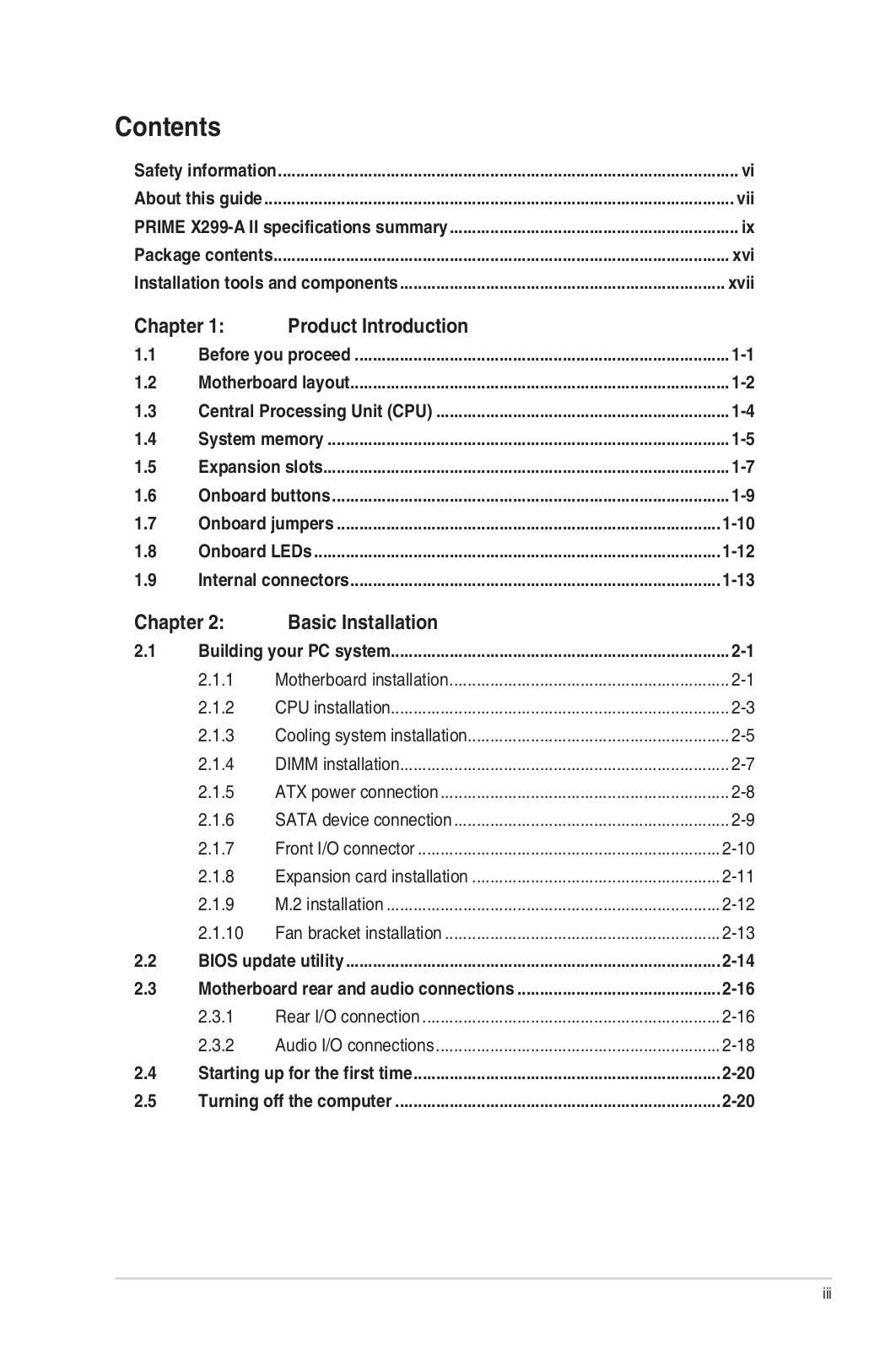
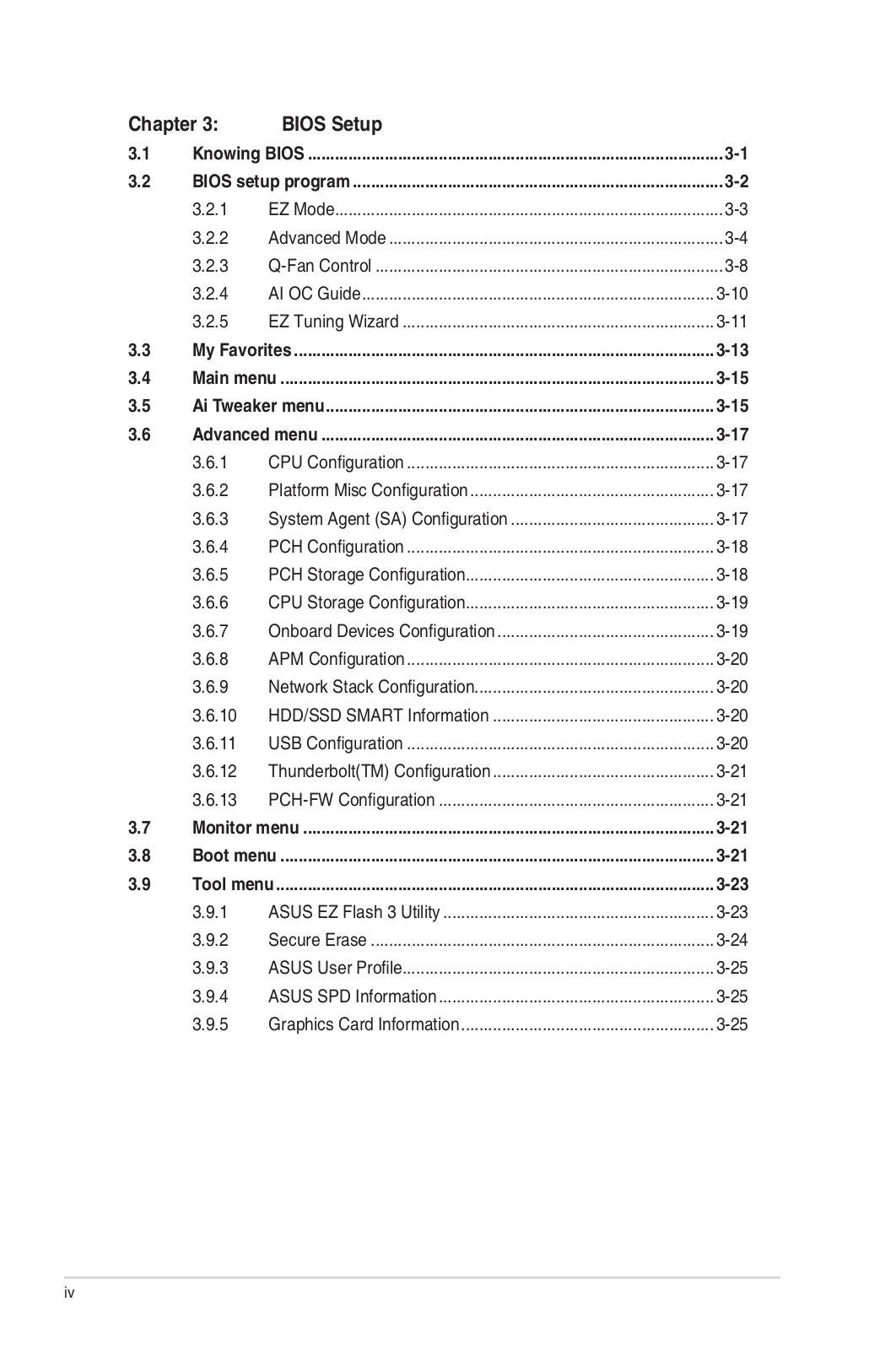
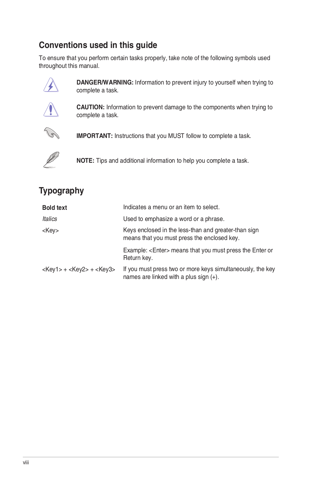
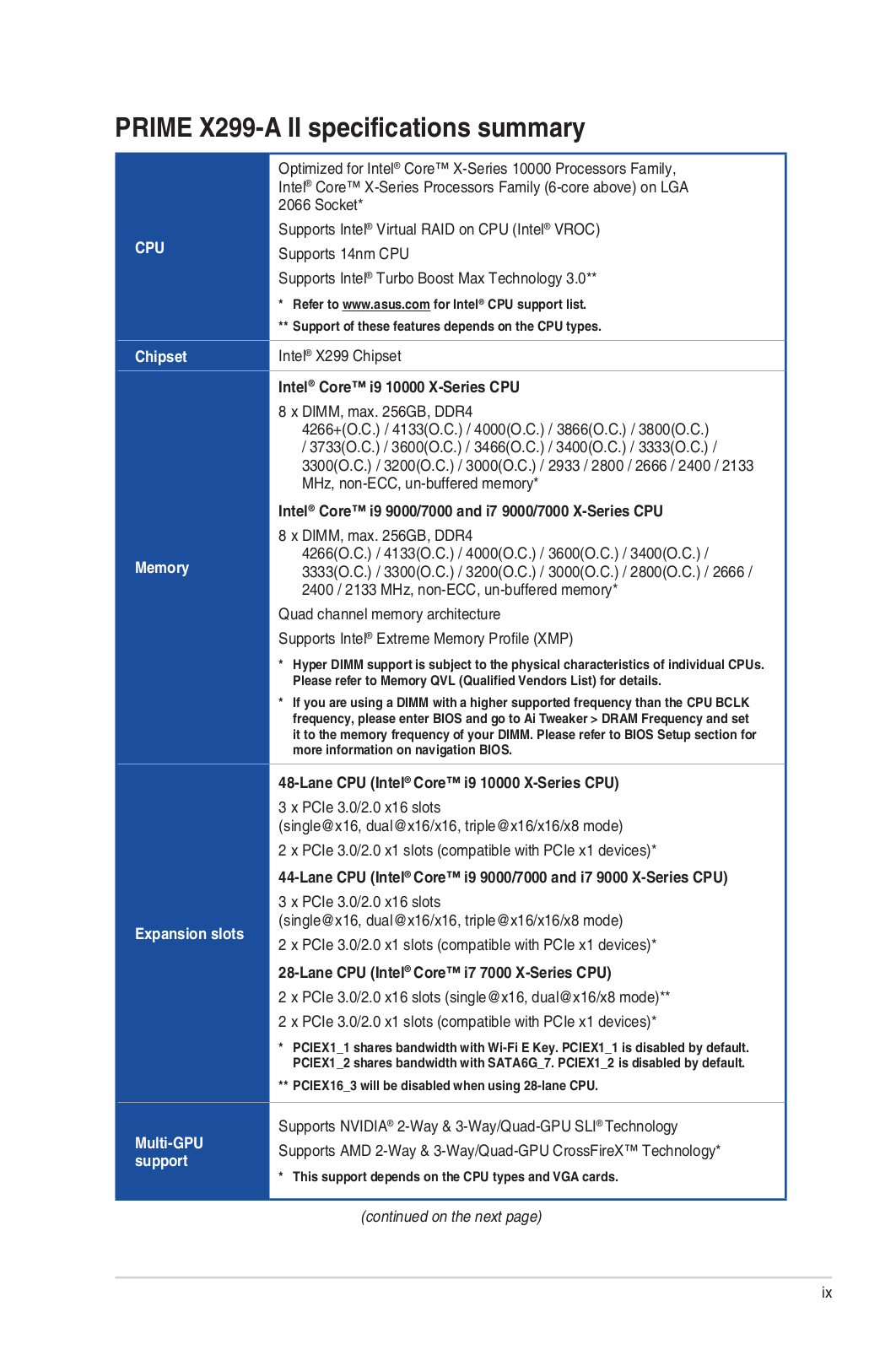
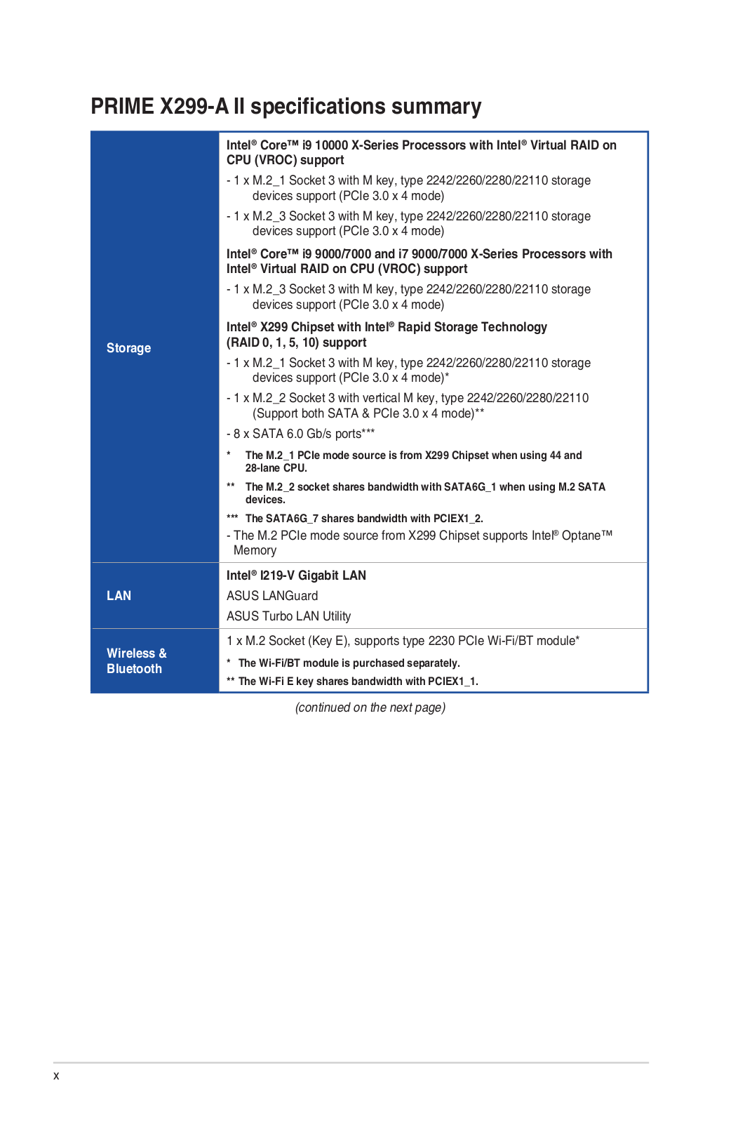
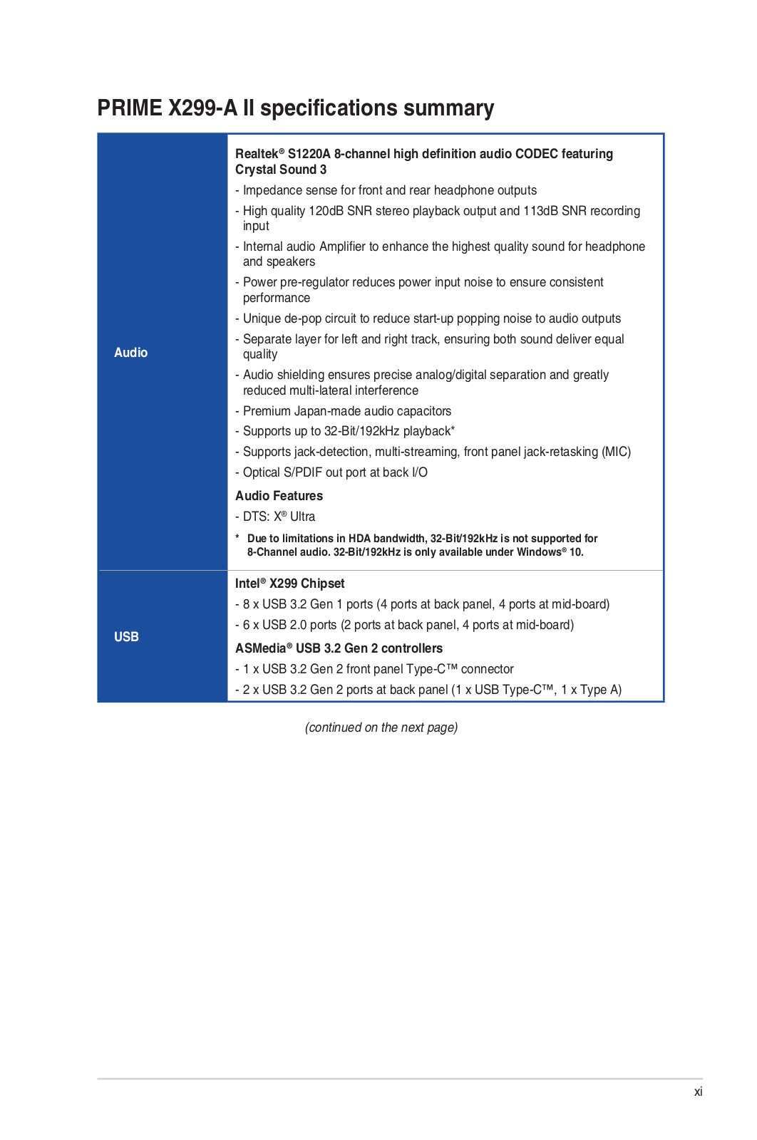
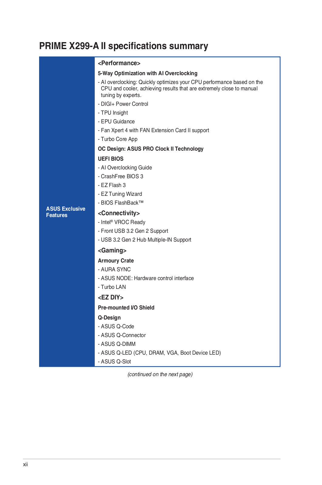
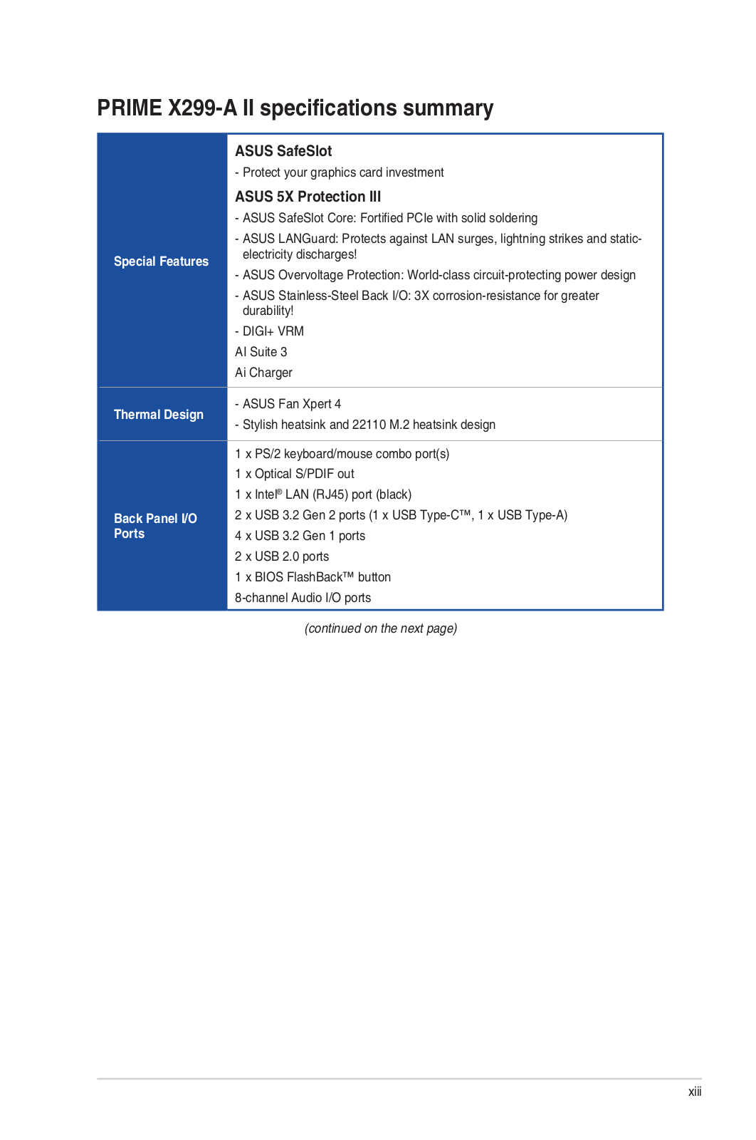
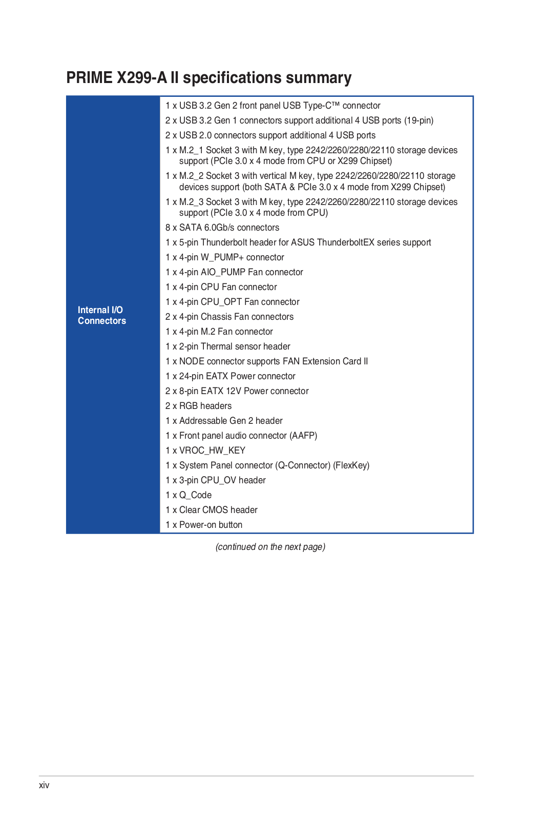
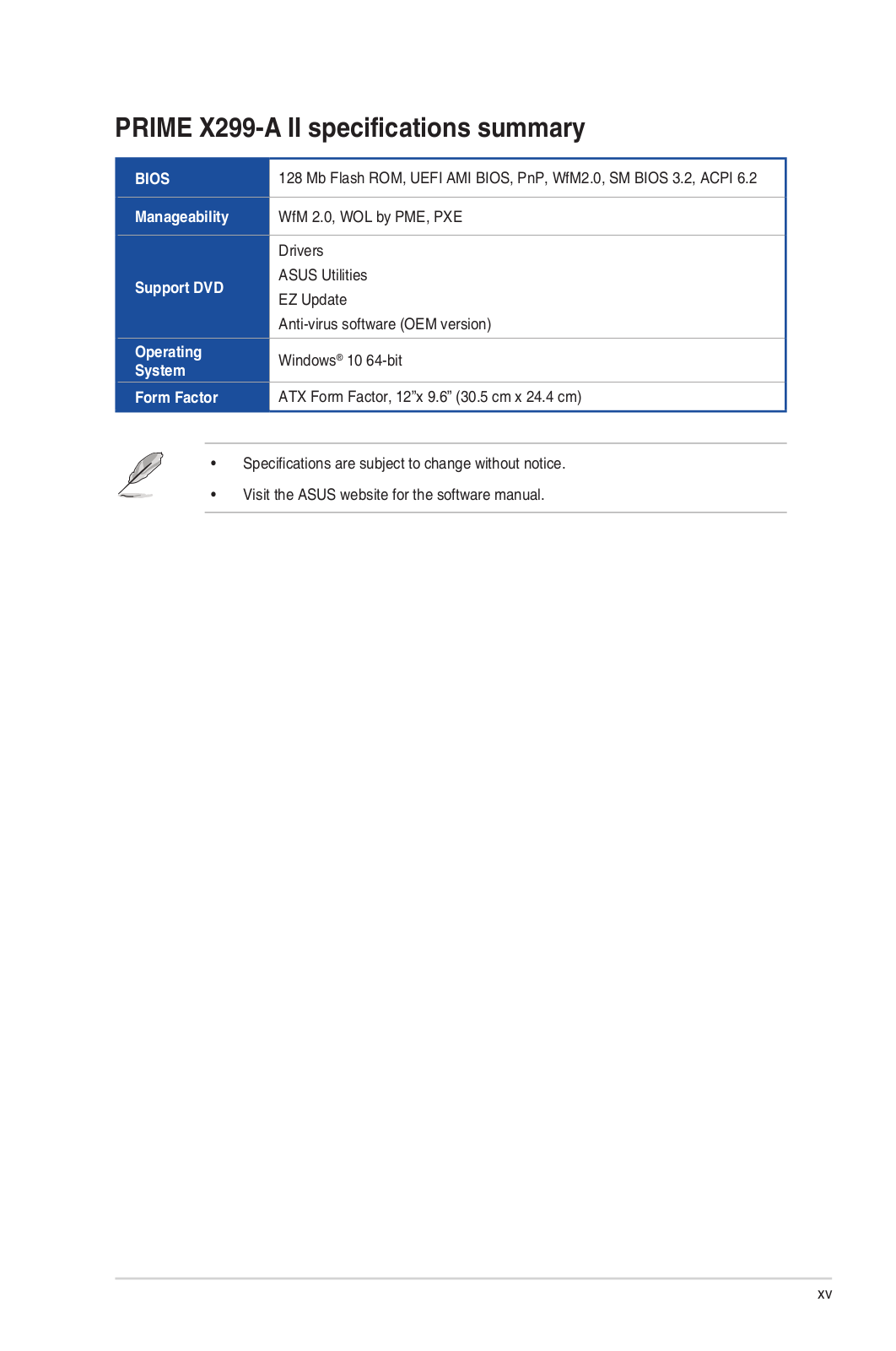
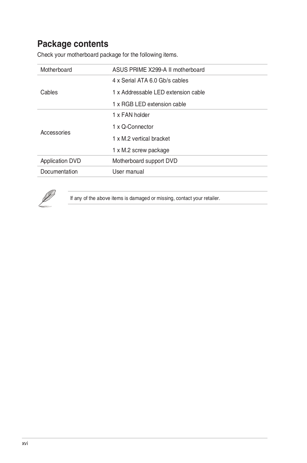
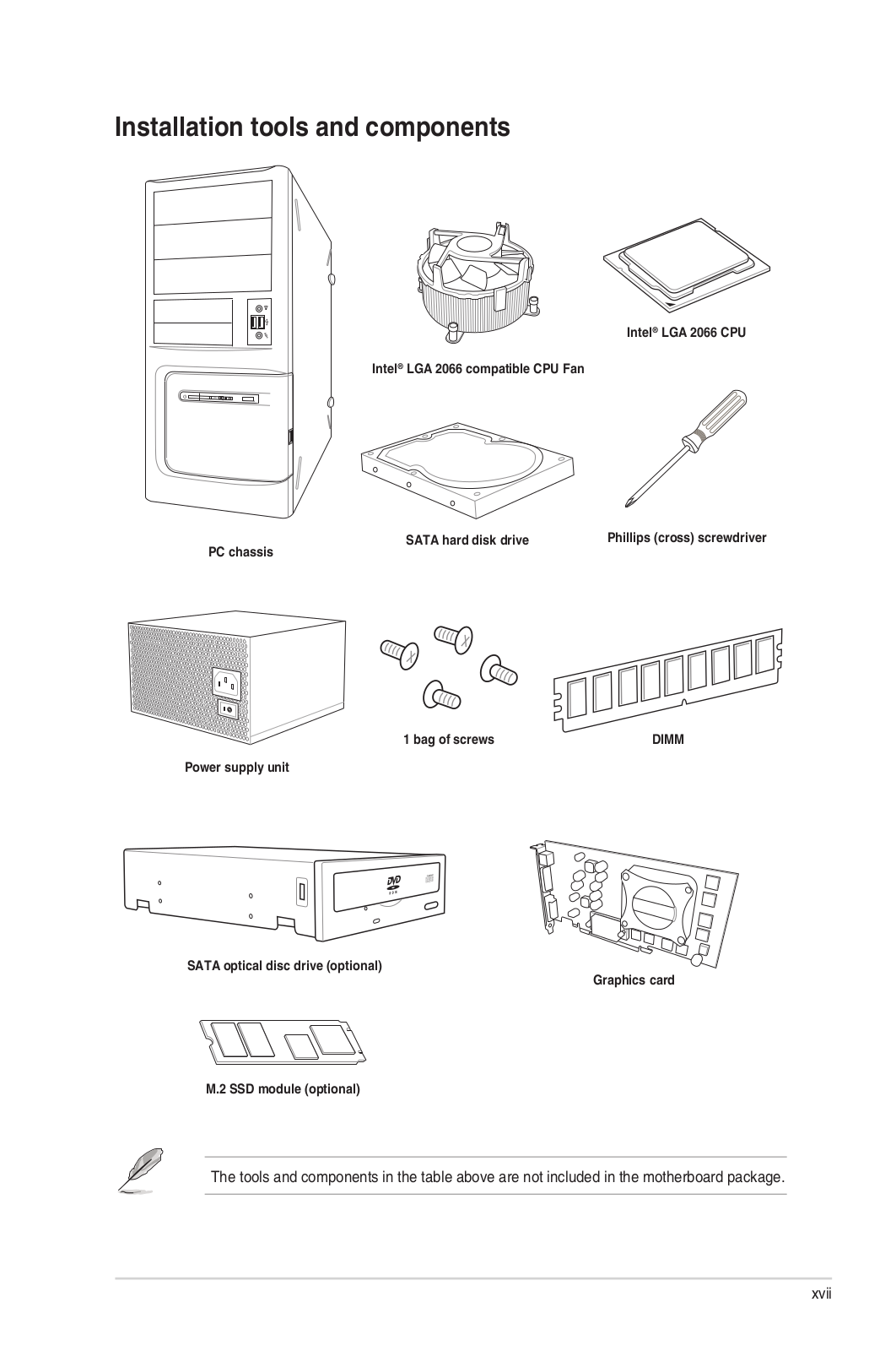

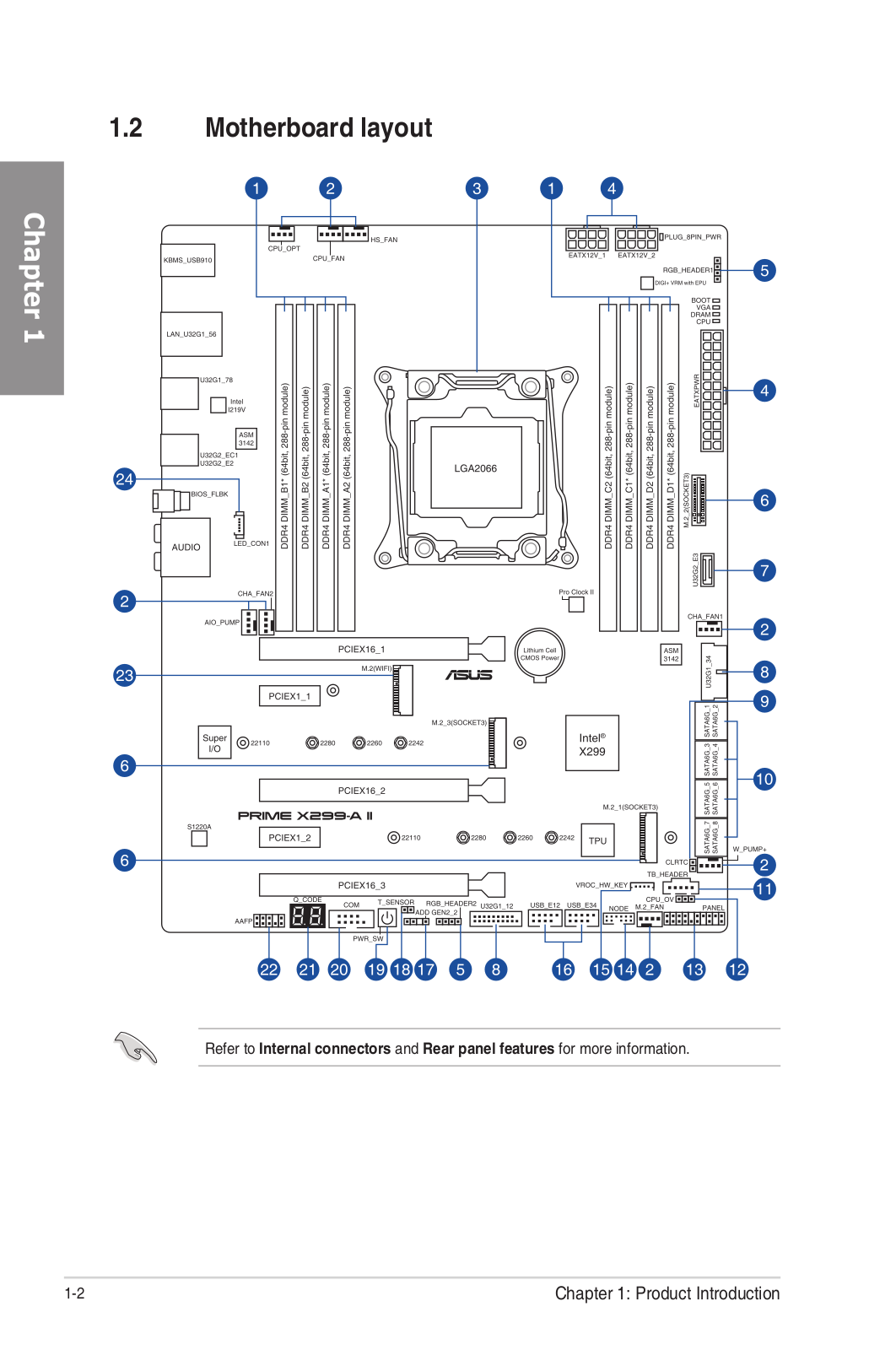
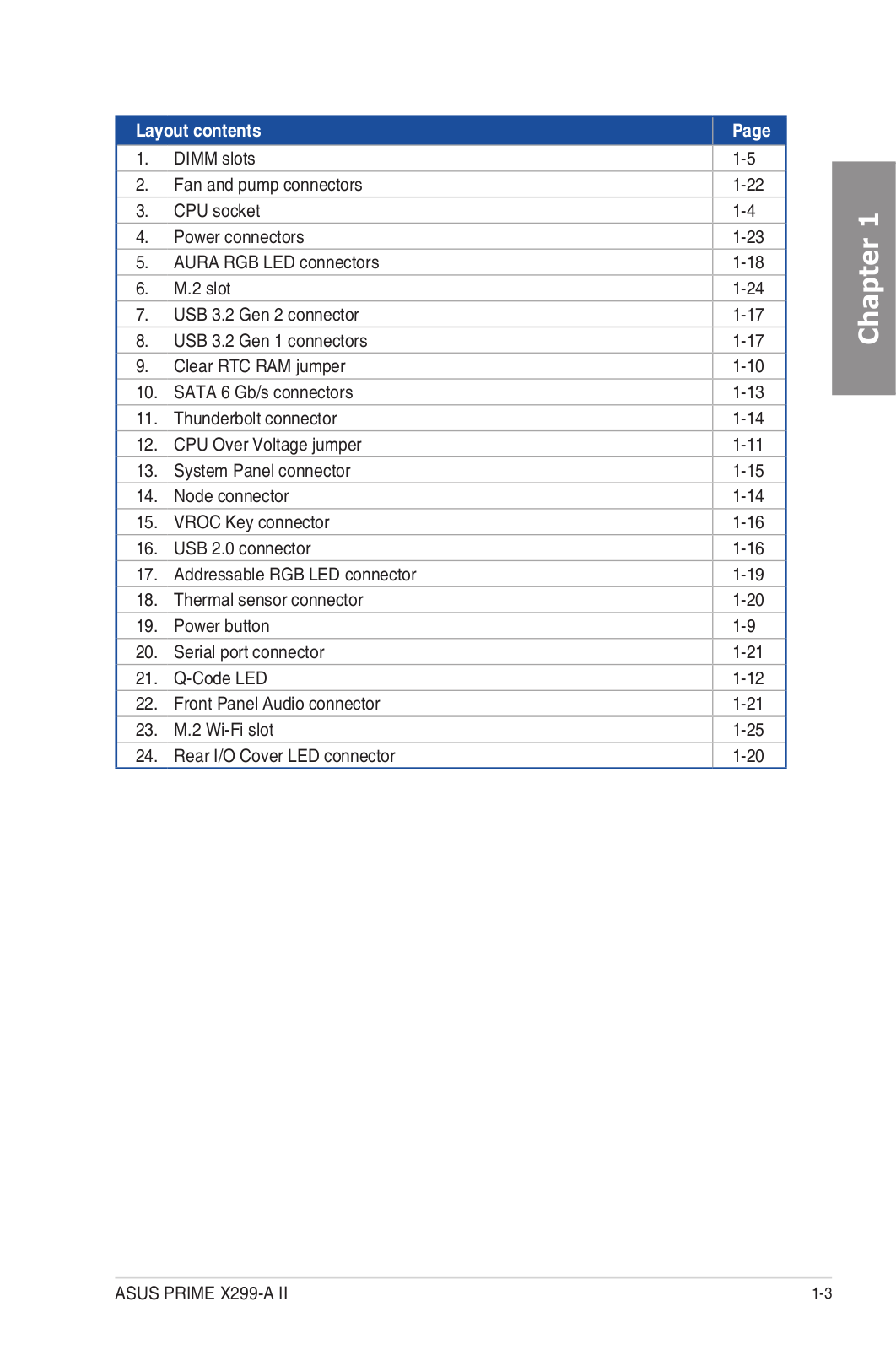
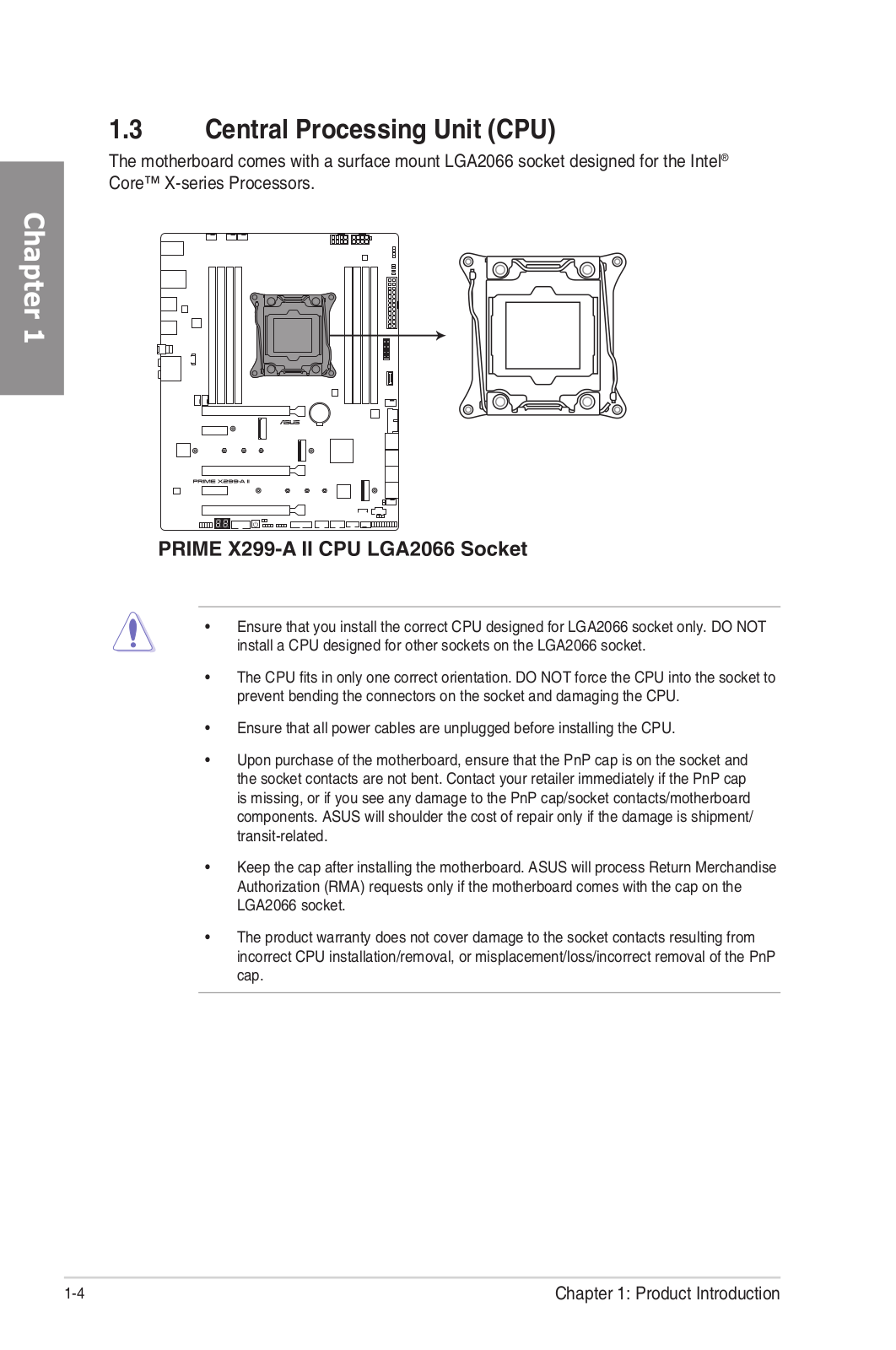
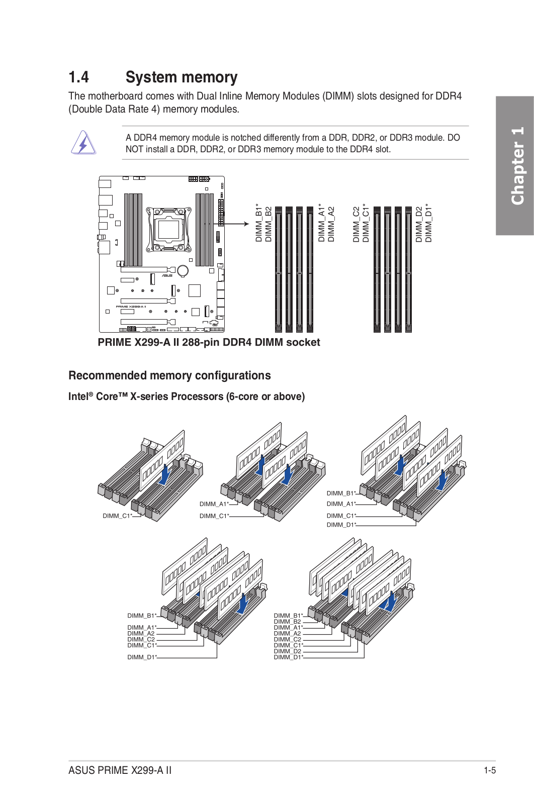
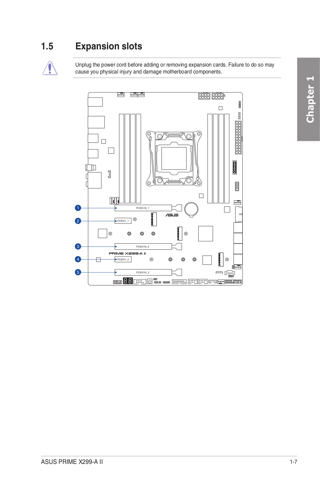
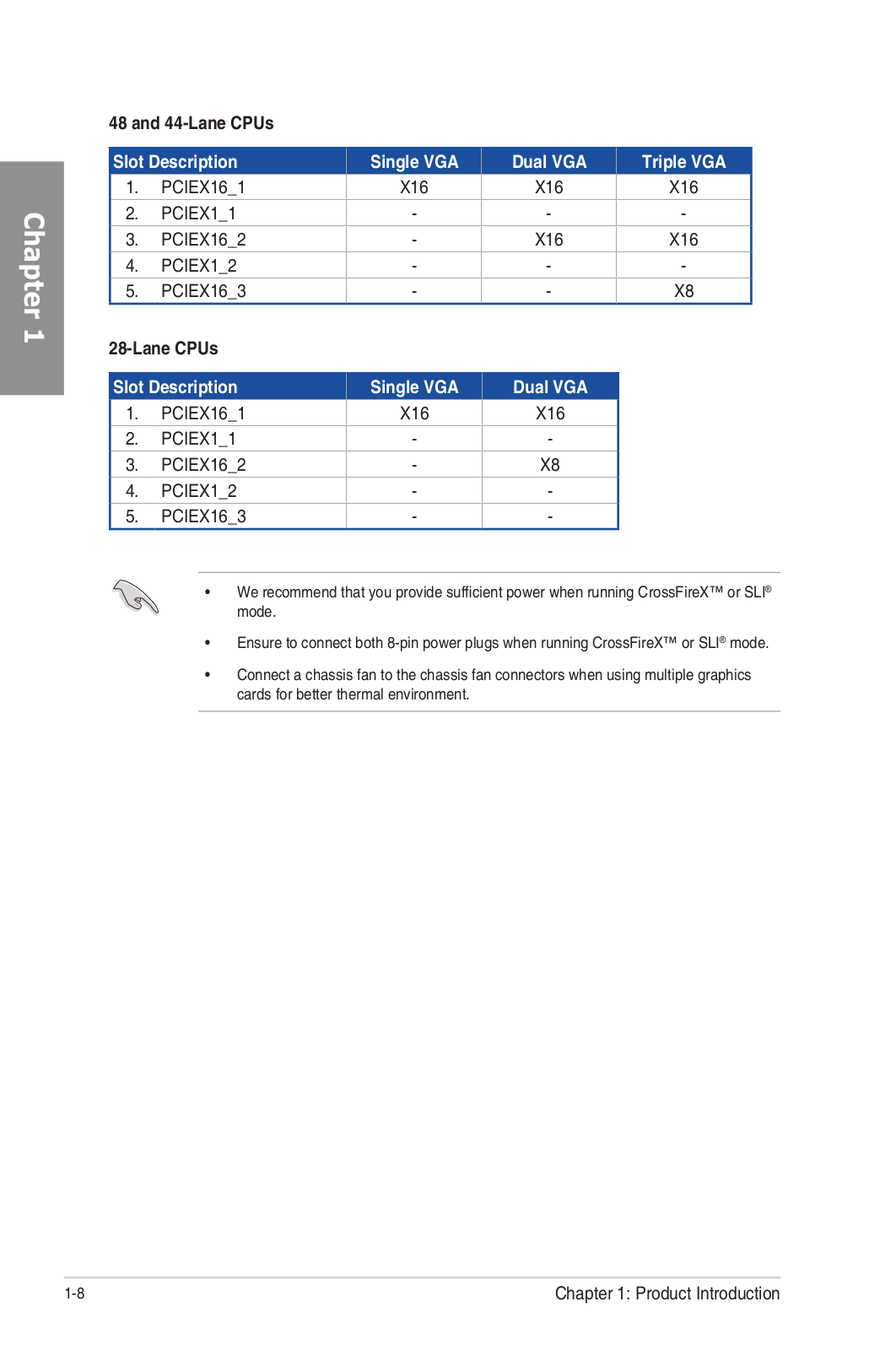
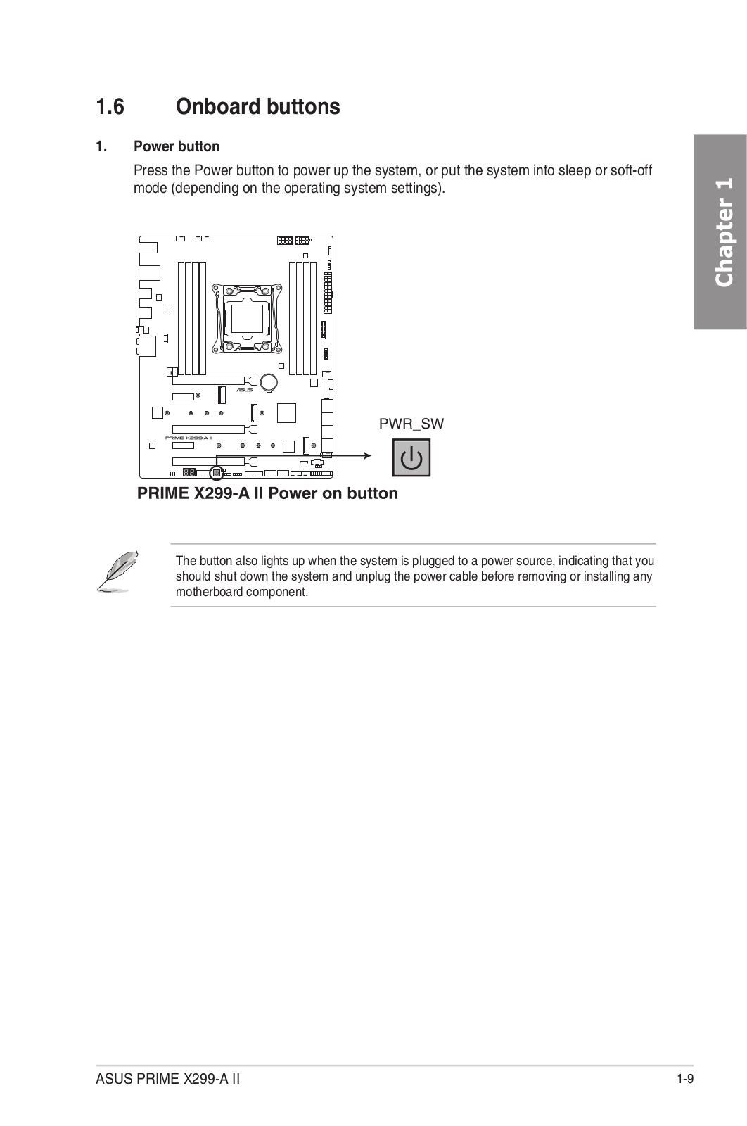
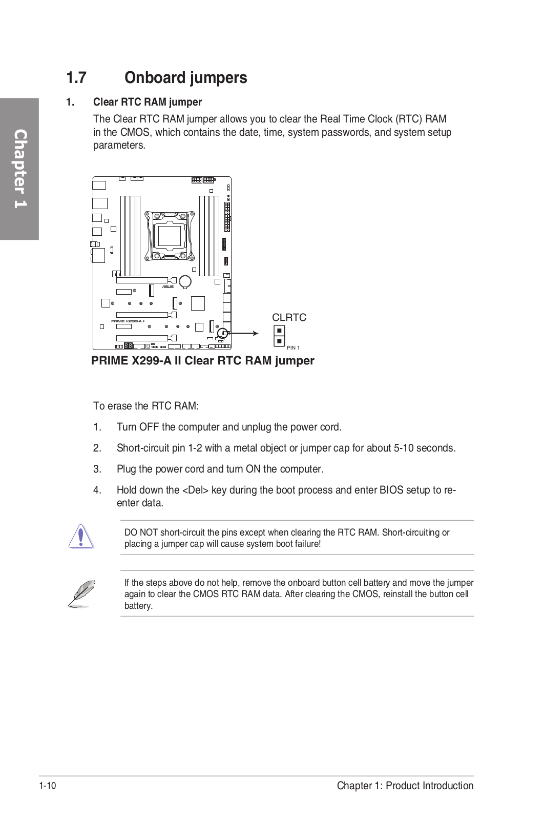
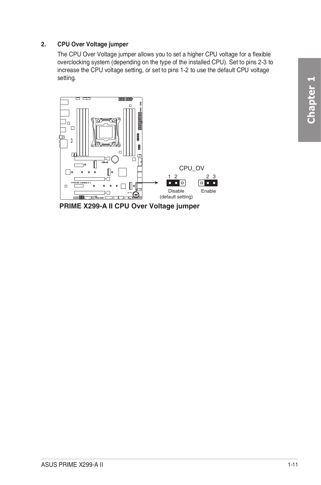
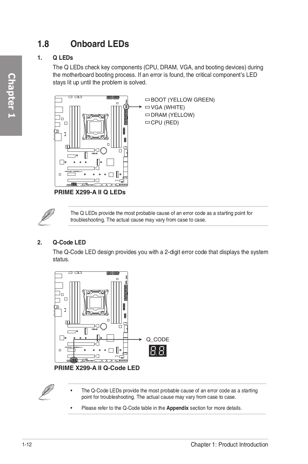
Loading…
+ 76 hidden pages
You need points to download manuals.
1 point = 1 manual.
You can buy points or you can get point for every manual you upload.
Buy points
Upload your manuals
Manufacturer:ASUS
Category:Computers & Peripherals
Device:ASUS Prime X299-A II
Name:PRIME X299 Series DRAM QVL
Language:Multilingual
Pages:10
Size:864.88 KB
Manufacturer:ASUS
Category:Computers & Peripherals
Device:ASUS Prime X299-A II
Name:User’s Manual (French Edition)
Language:Français
Pages:106
Size:7.73 MB
Manufacturer:ASUS
Category:Computers & Peripherals
Device:ASUS Prime X299-A II
Name:User’s Manual (Simplified Chinese Edition)
Language:中文(简体)
Pages:106
Size:8.12 MB
Manufacturer:ASUS
Category:Computers & Peripherals
Device:ASUS Prime X299-A II
Name:User’s Manual (German Edition)
Language:Deutsch
Pages:106
Size:7.05 MB
Manufacturer:ASUS
Category:Computers & Peripherals
Device:ASUS Prime X299-A II
Name:User’s Manual (Traditional Chinese Edition)
Language:中文(繁體)
Pages:104
Size:8.17 MB
Manufacturer:ASUS
Category:Computers & Peripherals
Device:ASUS Prime X299-A II
Name:User’s Manual (Japanese Edition)
Language:日本語
Pages:106
Size:8.75 MB
Manufacturer:ASUS
Category:Computers & Peripherals
Device:ASUS Prime X299-A II
Name:Intel_X299_DEVICE_QVL
Language:Multilingual
Pages:18
Size:884.76 KB
Manufacturer:ASUS
Category:Computers & Peripherals
Device:ASUS Prime X299-A II
Name:User’s Manual (English Edition)
Language:English
Pages:106
Size:8.24 MB
Manufacturer:ASUS
Category:Computers & Peripherals
Device:ASUS Prime X299-A II
Name:PRIME_X299_EDITION_30_device_QVL
Language:Multilingual
Pages:18
Size:683.75 KB
Материнская плата ASUS PRIME X299-A II, LGA 2066, Intel X299, ATX, Ret
- Форм-фактор: ATX
- Сокет: LGA 2066; чипсет: Intel X299
- Несколько видеокарт: SLI/CrossFireX
- Память: 8х DDR4; частотой до 2933 МГц
- Слоты: PCI-E 3.0 x16 х 3, PCI-E x1 х 2
- Разъемы: M.2 х 2
- Сеть: Gigabit Ethernet
Появились вопросы о товаре?
- Форм-фактор: ATX
- Сокет: LGA 2066; чипсет: Intel X299
- Несколько видеокарт: SLI/CrossFireX
- Память: 8х DDR4; частотой до 2933 МГц
- Слоты: PCI-E 3.0 x16 х 3, PCI-E x1 х 2
- Разъемы: M.2 х 2
- Сеть: Gigabit Ethernet
Появились вопросы о товаре?