

Motherboard
ROG STRIX
Z390-E
GAMING

ii
E14841
Revised Edition V2
September 2018
Copyright © 2018 ASUSTeK COMPUTER INC. All Rights Reserved.
No part of this manual, including the products and software described in it, may be reproduced,
transmitted, transcribed, stored in a retrieval system, or translated into any language in any form or by any
means, except documentation kept by the purchaser for backup purposes, without the express written
permission of ASUSTeK COMPUTER INC. (“ASUS”).
Product warranty or service will not be extended if: (1) the product is repaired, modied or altered, unless
such repair, modication of alteration is authorized in writing by ASUS; or (2) the serial number of the
product is defaced or missing.
ASUS PROVIDES THIS MANUAL “AS IS” WITHOUT WARRANTY OF ANY KIND, EITHER EXPRESS
OR IMPLIED, INCLUDING BUT NOT LIMITED TO THE IMPLIED WARRANTIES OR CONDITIONS OF
MERCHANTABILITY OR FITNESS FOR A PARTICULAR PURPOSE. IN NO EVENT SHALL ASUS, ITS
DIRECTORS, OFFICERS, EMPLOYEES OR AGENTS BE LIABLE FOR ANY INDIRECT, SPECIAL,
INCIDENTAL, OR CONSEQUENTIAL DAMAGES (INCLUDING DAMAGES FOR LOSS OF PROFITS,
LOSS OF BUSINESS, LOSS OF USE OR DATA, INTERRUPTION OF BUSINESS AND THE LIKE),
EVEN IF ASUS HAS BEEN ADVISED OF THE POSSIBILITY OF SUCH DAMAGES ARISING FROM ANY
DEFECT OR ERROR IN THIS MANUAL OR PRODUCT.
SPECIFICATIONS AND INFORMATION CONTAINED IN THIS MANUAL ARE FURNISHED FOR
INFORMATIONAL USE ONLY, AND ARE SUBJECT TO CHANGE AT ANY TIME WITHOUT NOTICE,
AND SHOULD NOT BE CONSTRUED AS A COMMITMENT BY ASUS. ASUS ASSUMES NO
RESPONSIBILITY OR LIABILITY FOR ANY ERRORS OR INACCURACIES THAT MAY APPEAR IN THIS
MANUAL, INCLUDING THE PRODUCTS AND SOFTWARE DESCRIBED IN IT.
Products and corporate names appearing in this manual may or may not be registered trademarks or
copyrights of their respective companies, and are used only for identication or explanation and to the
owners’ benet, without intent to infringe.
Offer to Provide Source Code of Certain Software
This product contains copyrighted software that is licensed under the General Public License (“GPL”),
under the Lesser General Public License Version (“LGPL”) and/or other Free Open Source Software
Licenses. Such software in this product is distributed without any warranty to the extent permitted by the
applicable law. Copies of these licenses are included in this product.
Where the applicable license entitles you to the source code of such software and/or other additional data,
you may obtain it for a period of three years after our last shipment of the product, either
(1) for free by downloading it from https://www.asus.com/support/
or
(2) for the cost of reproduction and shipment, which is dependent on the preferred carrier and the location
where you want to have it shipped to, by sending a request to:
ASUSTeK Computer Inc.
Legal Compliance Dept.
15 Li Te Rd.,
Beitou, Taipei 112
Taiwan
In your request please provide the name, model number and version, as stated in the About Box of the
product for which you wish to obtain the corresponding source code and your contact details so that we
can coordinate the terms and cost of shipment with you.
The source code will be distributed WITHOUT ANY WARRANTY and licensed under the same license as
the corresponding binary/object code.
This offer is valid to anyone in receipt of this information.
ASUSTeK is eager to duly provide complete source code as required under various Free Open Source
Software licenses. If however you encounter any problems in obtaining the full corresponding source
code we would be much obliged if you give us a notication to the email address gpl@asus.com, stating
the product and describing the problem (please DO NOT send large attachments such as source code
archives, etc. to this email address).

iii
Contents
Safety information ………………………………………………………………………………………… vi
About this guide ………………………………………………………………………………………….. vii
ROG STRIX Z390-E GAMING specifications summary ……………………………………. ix
Package contents ……………………………………………………………………………………….. xiv
Installation tools and components ……………………………………………………………….. xv
Chapter 1: Product Introduction
1.1 Motherboard overview …………………………………………………………………….1-1
1.1.1 Before you proceed …………………………………………………………… 1-1
1.1.2 Motherboard layout …………………………………………………………… 1-2
1.1.3 Central Processing Unit (CPU) …………………………………………… 1-4
1.1.4 System memory ……………………………………………………………….. 1-5
1.1.5 Expansion slots ………………………………………………………………… 1-7
1.1.6 Onboard buttons and switches…………………………………………….1-9
1.1.7 Jumper ………………………………………………………………………….. 1-10
1.1.8 Onboard LEDs ……………………………………………………………….. 1-12
1.1.9 Internal connectors…………………………………………………………..1-13
Chapter 2: Basic Installation
2.1 Building your PC system …………………………………………………………………2-1
2.1.1 CPU installation…………………………………………………………………2-1
2.1.2 Cooling system installation…………………………………………………. 2-2
2.1.3 Motherboard installation …………………………………………………….. 2-5
2.1.4 DIMM installation………………………………………………………………. 2-6
2.1.5 ATX power connection ………………………………………………………. 2-7
2.1.6 SATA device connection ……………………………………………………. 2-8
2.1.7 Front I/O connector …………………………………………………………… 2-9
2.1.8 Expansion card installation ………………………………………………. 2-10
2.1.9 M.2 installation ……………………………………………………………….. 2-12
2.1.10 Wi-Fi antenna installation …………………………………………………. 2-13
2.1.11 ASUS fan holder installation …………………………………………….. 2-14
2.2 Motherboard rear and audio connections ………………………………………2-15
2.2.1 Rear I/O connection ………………………………………………………… 2-15
2.2.2 Audio I/O connections ……………………………………………………… 2-17
2.3 Starting up for the first time …………………………………………………………..2-19
2.4 Turning off the computer ………………………………………………………………2-19

iv
Chapter 3: BIOS Setup
3.1 Knowing BIOS ………………………………………………………………………………..3-1
3.2 BIOS setup program ……………………………………………………………………….3-2
3.2.1 Advanced Mode ……………………………………………………………….. 3-3
3.2.2 EZ Mode…………………………………………………………………………..3-7
3.2.3 Q-Fan Control ………………………………………………………………….. 3-8
3.2.4 AI OC Guide …………………………………………………………………… 3-10
3.2.5 EZ Tuning Wizard …………………………………………………………… 3-11
3.3 My Favorites …………………………………………………………………………………3-13
3.4 Main menu ……………………………………………………………………………………3-15
3.5 Ai Tweaker menu …………………………………………………………………………..3-15
3.6 Advanced menu ……………………………………………………………………………3-17
3.6.1 Platform Misc Conguration ……………………………………………… 3-17
3.6.2 CPU Conguration ………………………………………………………….. 3-17
3.6.3 System Agent (SA) Conguration ……………………………………… 3-18
3.6.4 PCH Conguration ………………………………………………………….. 3-18
3.6.5 PCH Storage Conguration………………………………………………. 3-18
3.6.6 PCH-FW Conguration ……………………………………………………. 3-19
3.6.7 Onboard Devices Conguration ………………………………………… 3-19
3.6.8 APM Conguration ………………………………………………………….. 3-20
3.6.9 PCI Subsystem Settings ………………………………………………….. 3-20
3.6.10 USB Conguration ………………………………………………………….. 3-20
3.6.11 Network Stack Conguration…………………………………………….. 3-20
3.6.12 NVMe Conguration ………………………………………………………… 3-20
3.6.13 HDD/SSD SMART Information …………………………………………. 3-20
3.7 Monitor menu ……………………………………………………………………………….3-21
3.8 Boot menu ……………………………………………………………………………………3-21
3.9 Tool menu ……………………………………………………………………………………. 3-23
3.9.1 ASUS EZ Flash 3 Utility …………………………………………………… 3-23
3.9.2 ASUS Secure Erase…………………………………………………………3-24
3.9.3 ASUS User Prole…………………………………………………………… 3-25
3.9.4 ASUS SPD Information ……………………………………………………. 3-25
3.9.5 Graphics Card Information ……………………………………………….. 3-25
3.10 Exit menu …………………………………………………………………………………….. 3-26
3.11 Updating BIOS ………………………………………………………………………………3-27
3.11.1 EZ Update ……………………………………………………………………… 3-27
3.11.2 ASUS EZ Flash 3 ……………………………………………………………. 3-28
3.11.3 ASUS CrashFree BIOS 3 …………………………………………………. 3-30

v
Chapter 4: RAID Support
4.1 RAID configurations ……………………………………………………………………….4-1
4.1.1 RAID denitions ……………………………………………………………….. 4-1
Appendix
Notices …………………………………………………………………………………………………….. A-1
ASUS contact information ………………………………………………………………………….. A-7

vi
Safety information
Electrical safety
• To prevent electrical shock hazard, disconnect the power cable from the electrical outlet
before relocating the system.
• When adding or removing devices to or from the system, ensure that the power cables
for the devices are unplugged before the signal cables are connected. If possible,
disconnect all power cables from the existing system before you add a device.
• Before connecting or removing signal cables from the motherboard, ensure that all
power cables are unplugged.
• Seek professional assistance before using an adapter or extension cord. These devices
could interrupt the grounding circuit.
• Ensure that your power supply is set to the correct voltage in your area. If you are not
sure about the voltage of the electrical outlet you are using, contact your local power
company.
• If the power supply is broken, do not try to x it by yourself. Contact a qualied service
technician or your retailer.
Operation safety
• Before installing the motherboard and adding devices on it, carefully read all the manuals
that came with the package.
• Before using the product, ensure all cables are correctly connected and the power
cables are not damaged. If you detect any damage, contact your dealer immediately.
• To avoid short circuits, keep paper clips, screws, and staples away from connectors,
slots, sockets and circuitry.
• Avoid dust, humidity, and temperature extremes. Do not place the product in any area
where it may become wet.
• Place the product on a stable surface.
• If you encounter technical problems with the product, contact a qualied service
technician or your retailer.
• Your motherboard should only be used in environments with ambient temperatures
between 0°C and 40°C.

vii
About this guide
This user guide contains the information you need when installing and conguring the
motherboard.
How this guide is organized
This guide contains the following parts:
• Chapter1:ProductIntroduction
This chapter describes the features of the motherboard and the new technology it
supports. It includes description of the switches, jumpers, and connectors on the
motherboard.
• Chapter2:BasicInstallation
This chapter lists the hardware setup procedures that you have to perform when
installing system components.
• Chapter3:BIOSSetup
This chapter tells how to change system settings through the BIOS Setup menus.
Detailed descriptions of the BIOS parameters are also provided.
• Chapter4:RAIDSupport
This chapter describes the RAID congurations.
Where to find more information
Refer to the following sources for additional information and for product and software
updates.
1. ASUS website
The ASUS website (www.asus.com) provides updated information on ASUS hardware
and software products.
2. Optional documentation
Your product package may include optional documentation, such as warranty yers,
that may have been added by your dealer. These documents are not part of the
standard package.

viii
Conventions used in this guide
To ensure that you perform certain tasks properly, take note of the following symbols used
throughout this manual.
DANGER/WARNING: Information to prevent injury to yourself when trying to
complete a task.
CAUTION: Information to prevent damage to the components when trying to
complete a task.
IMPORTANT: Instructions that you MUST follow to complete a task.
NOTE: Tips and additional information to help you complete a task.
Typography
Bold text Indicates a menu or an item to select.
Italics
Used to emphasize a word or a phrase.
<Key> Keys enclosed in the less-than and greater-than sign
means that you must press the enclosed key.
Example: <Enter> means that you must press the Enter or
Return key.
<Key1> + <Key2> + <Key3> If you must press two or more keys simultaneously, the key
names are linked with a plus sign (+).

ix
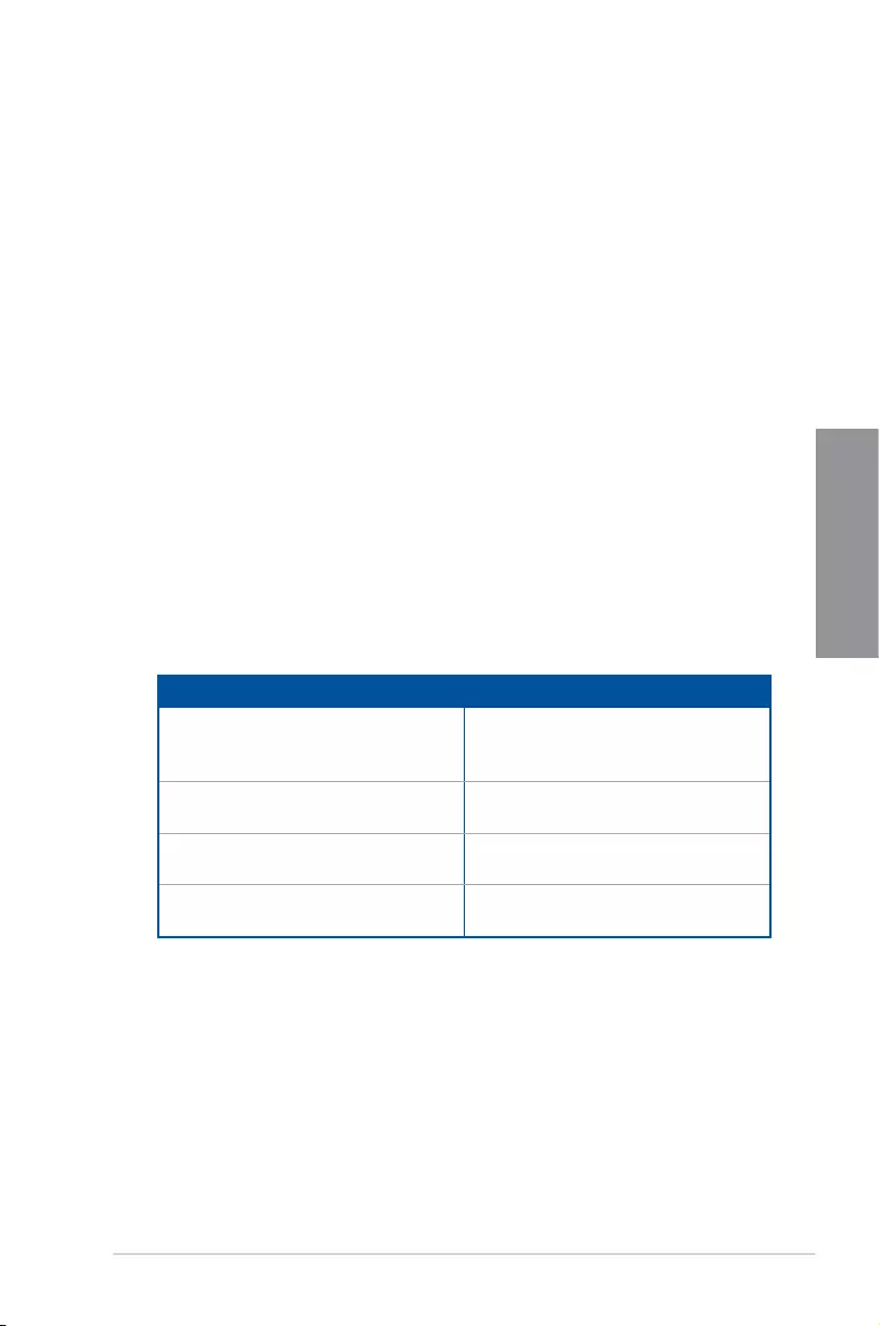
ROG STRIX Z390-E GAMING specifications summary
CPU
Socket 1151 for 9th / 8th Gen Intel® Core™, Pentium® Gold and
Celeron® processors
Supports 14nm CPU
Supports Intel® Turbo Boost Technology 2.0*
* Intel® Turbo Boost Technology 2.0 support depends on the CPU type.
** Refer to www.asus.com for CPU support list.
Chipset Intel® Z390 Chipset
Memory
4 x DIMM, max. 64GB DDR4 4266+(O.C.)* / 4133(OC)* / 4000(OC)*
/ 3866(OC)* / 3733(OC)* / 3600(OC)* / 3466(OC)* / 3400(OC)* /
3333(OC)* / 3300(OC)* / 3200(OC)* / 3000(OC)* / 2800(OC)* /
2666 / 2400 / 2133 MHz, non-ECC, un-buffered memory
Dual channel memory architecture
Supports Intel® Extreme Memory Prole (XMP)
* Hyper DIMM support is subject to the physical characteristics of
individual CPUs. Please refer to Memory QVL(Qualified Vendors List)
for details.
Expansion Slots
Socket 1151 for 9th / 8th Gen Intel® Core™, Pentium® Gold and
Celeron® processors
2 x PCIe 3.0 x16 slots (support x16, x8/x8)
Intel® Z390 Chipset
1 x PCIe 3.0 x16 slot (max. at x4 mode)*
3 x PCIe 3.0 x1 slots
* The PCIe x16_3 slot shares bandwidth with SATA6G_56. The PCIe
x16_3 is set at x2 mode by default.
Graphic
Integrated Graphics Processor — Intel® UHD Graphics support
Multi-VGA output support: HDMI/DisplayPort
— Supports DisplayPort 1.2 with max. resolution 4096 x 2304@60Hz
— Supports HDMI 1.4b with max. resolution 4096 x 2160@30Hz
Multi-GPU Support Supports NVIDIA® 2-Way/Quad-GPU SLI™ Technology
Supports AMD® 3-Way/Quad-GPU CrossFireX™ Technology
Storage
Intel® Z390 Chipset with RAID 0, 1, 5, 10, and Intel Rapid
Storage Technology support
— 1 x M.2_1 Socket 3 with M Key, type 2242/2260/2280
(PCIe 3.0 x4 and SATA modes)*
— 1 x M.2_2 Socket 3 with M Key, type 2242/2260/2280/22110
(supports PCIe 3.0 x4 mode)
— 6 x SATA 6Gb/s ports
— Intel® Optane™ Memory Ready
* When the M.2_1(Socket 3) is operating in SATA mode, SATA port 2
(SATA6G_2) will be disabled.
(continued on the next page)

x
(continued on the next page)
LAN
Intel® I219-V Gigabit LAN- Dual interconnect between the integrated
Media Access Controller (MAC) and physical layer (PHY)
Anti-surge LANGuard
ROG GameFirst V technology
Wireless Data Network
Intel® Wireless-AC 9560
2 x 2 Wi-Fi with MU-MIMO 802.11 a/b/g/n/ac supports dual
frequency band 2.4/5 GHz
Supports channel bandwidth: HT20/HT40/HT80/HT160. Up to
1.73Gbps transfer speed
Bluetooth Bluetooth v5.0
Audio
ROG SupremeFX S1220A 8-Channel High Definition Audio
CODEC
— Supports up to 32-Bit/192kHz playback*
— Impedance sense for front and rear headphone outputs
— High quality 120dB SNR stereo playback output and 113dB SNR
recording input
— SupremeFX Shielding Technology
— Dual OP Ampliers
— Jack-detection, Multi-streaming, and Front Panel Jack-retasking
— Optical S/PDIF out port at back panel
Audio Features:
— Sonic Studio III + Sonic Studio Link
— Sonic Radar III
* Due to limitations in HDA bandwidth, 32-Bit/192kHz is not supported for
8-Channel audio.
USB
Intel® Z390 Chipset
— 1 x USB 3.1 Gen 2 front panel connector
— 4 x USB 3.1 Gen 2 ports
(3 Type-A [red] and 1 Type-C [black] at back panel)
— 4 x USB 3.1 Gen 1 ports
(2 ports at back panel [blue], 2 ports at mid-board)
— 6 x USB 2.0 ports
(2 ports at back panel [black], 4 ports at mid-board)
ROG STRIX Z390-E GAMING specifications summary

xi
(continued on the next page)
ROG Exclusive Features
ROG RAMCache III
ROG GameFirst V
ROG CPU-Z
ROG Overwolf
Special Feature
Aura
— Aura Lighting Control
— Aura RGB Strip Headers
— Aura Lighting Effects Synchronization with compatible ASUS ROG
devices
— Aura Addressable Strip Header
ASUS Dual Intelligent Processors 5-Way Optimization by Dual
Intelligent Processors 5
— 5-Way Optimization tuning perfectly consolidates TPU Insight,
EPU Guidance, DIGI+ VRM, Fan Expert 4, and Turbo App
Gamer’s Guardian
— Procool
— SafeSlot
— DIGI+ VRM
— DRAM Overcurrent Protection
— ESD Guards on VGA, LAN, Audio and USB3.1/2.0 ports
— Highly Durable Components
ASUS Exclusive Features
— Armoury crate
— Pre-mounted I/O Shield
— ASUS NODE: hardware control interface
— OptiMem II
— 3D Printing Friendly design
— AI Suite 3
— MemOK! II
— AI Charger
ASUS EZ DIY
— ASUS CrashFree BIOS 3
— ASUS EZ Flash 3
ASUS Q-Design
— Q-LED (CPU, DRAM, VGA, Boot Device LED)
— Q-Slot
— Q-DIMM
ROG STRIX Z390-E GAMING specifications summary

xii
Back I/O Ports
1 x PS/2 keyboard/mouse combo port
1 x HDMI port
1 x DP port
2 x USB2.0 ports
2 x USB 3.1 Gen 1 ports [blue]
4 x USB3.1 Gen 2 ports
(3 x Type-A [red] and 1 x Type-C ports [black])
1 x Anti-surge LAN (RJ45) port
1 x ASUS Wi-Fi module
(Wi-Fi 802.11 a/b/g/n/ac and Bluetooth v5.0.)
5 x Audio jacks
1 x Optical S/PDIF out
Internal I/O Ports
1 x USB 3.1 Gen 2 front panel connector
1 x USB 3.1 Gen 1 header supports additional 2 USB 3.1 Gen 1
ports
2 x USB 2.0 header supports additional 4 USB 2.0 ports
6 x SATA 6Gb/s ports
1 x M.2 Socket 3 with M Key, type 2242/2260/2280 storage devices
support (both SATA & PCIe 3.0 x 4 modes)
1 x M.2 Socket 3 with M Key, type 2242/2260/2280/22110 storage
devices support (PCIe 3.0 x 4 mode)
1 x 4-Pin CPU FAN connector
1 x 4-Pin CPU_OPT fan connector
2 x 4-Pin Chassis fan connectors
1 x M.2 FAN connector
1 x 4-Pin AIO_PUMP connector
1 x 4-Pin W_PUMP+ connector
1 x EXT_FAN header
1 x Thermal sensor connector
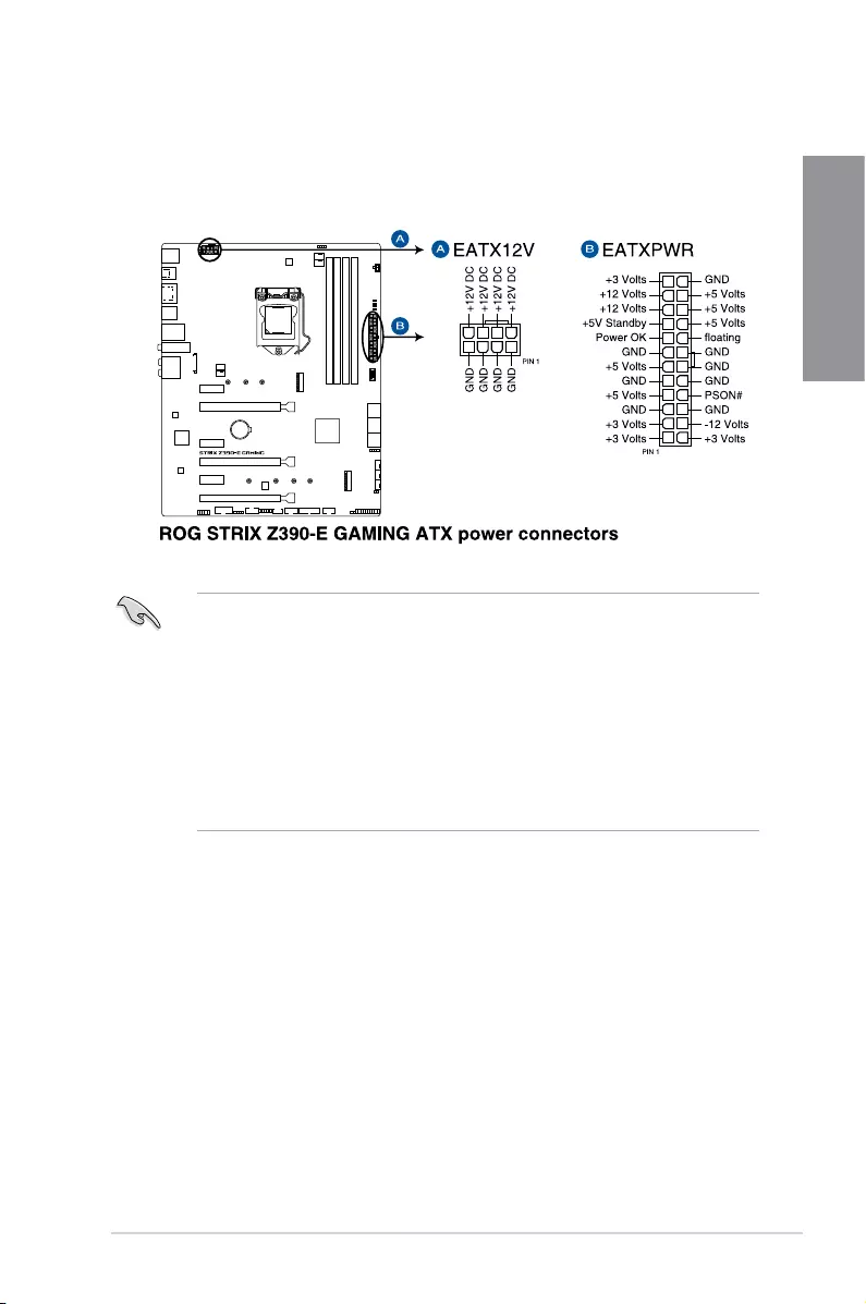
1 x 24-pin EATX power connector
1 x 8-pin EATX 12V power connector
2 x Aura RGB headers
1 x Addressable header
1 x MemOK! II switch
1 x Node connector
1 x Clear CMOS jumper (2-pin)
1 x COM port
1 x TPM header
1 x CPU OV header
1 x Front panel audio connector (AAFP)
1 x System panel connector
(continued on the next page)
ROG STRIX Z390-E GAMING specifications summary

xiii
Specications are subject to change without notice. Please refer to the ASUS website for
the latest specications.
ROG STRIX Z390-E GAMING specifications summary
BIOS 1 x 128 Mb Flash ROM, UEFI AMI BIOS, PnP, DMI3.0,
SM BIOS 3.1, ACPI 6.1
Manageability WOL, PXE
Support DVD
Drivers
ASUS Utilities
EZ Update
Anti-virus software (OEM version)
Operating System Support Windows® 10 64-bit
Form Factor ATX Form Factor, 12” x 9.6” (30.5 cm x 24.4 cm)

xiv
Package contents
Check your motherboard package for the following items.
Motherboard 1 x ROG STRIX Z390-E GAMING motherboard
Cables
2 x 2-in-1 SATA 6Gb/s cables
1 x Thermal sensor cable
1 x Extension cable for RGB strips (80cm)
1 x Extension cable for Addressable LED strips (80cm)
Accessories
1 x ASUS 2×2 dual band Wi-Fi antenna
(Wi-Fi 802.11a/b/g/n/ac compliant)
1 x SLI™ HB Bridge(2-way-M)
1 x M.2 screws package
1 x ROG Strix door hanger
1 x 4010 Fan
1 x Fan screws package
1 x ROG Strix series sticker
1 x Cable ties pack
Application DVD 1 x ROG motherboard support DVD
Documentation 1 x User guide
Others 1 x ROG Strix Thank you card
If any of the above items is damaged or missing, contact your retailer.
xv
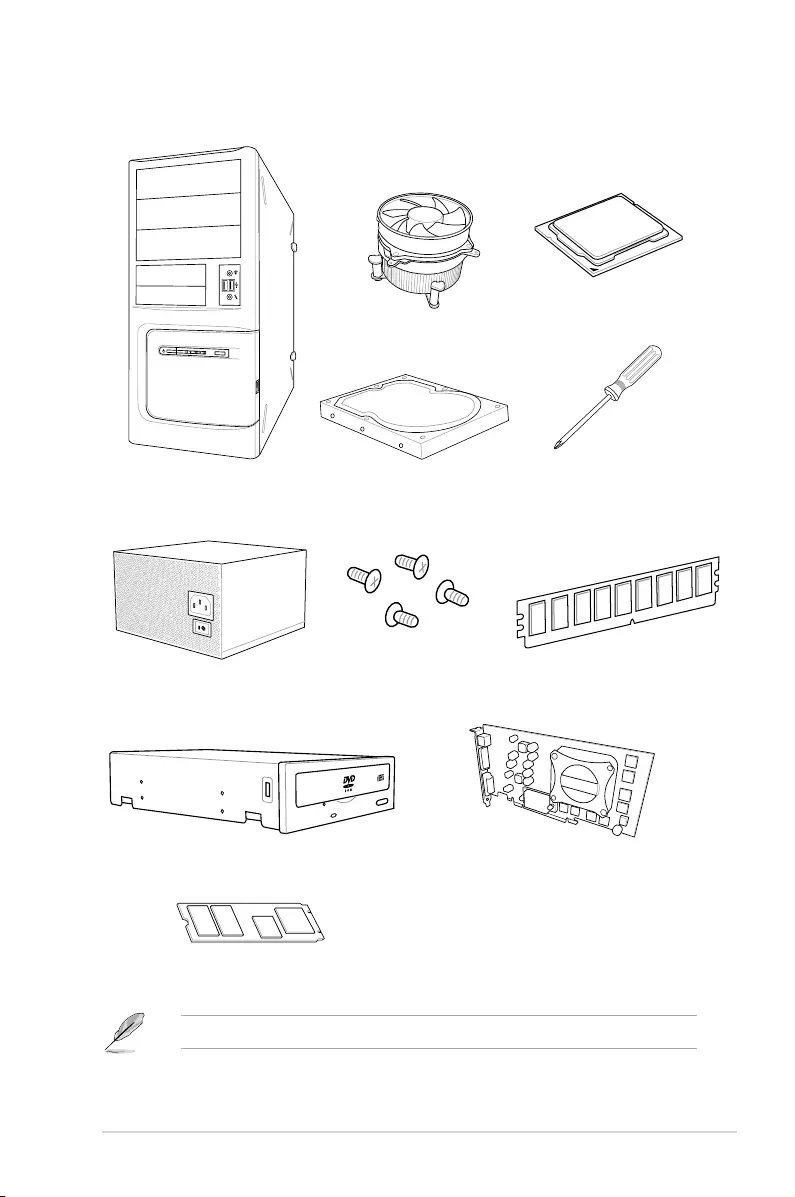
Installation tools and components
PC chassis
Power supply unit
Intel® LGA1151 compatible CPU Fan
Intel® LGA1151 CPU
DIMM
SATA hard disk drive
Graphics card (optional)
Phillips (cross) screwdriver
SATA optical disc drive (optional)
1 bag of screws
The tools and components above are not included in the motherboard package.
M.2 SSD module (optional)

xvi

ROG STRIX Z390-E GAMING 1-1
Chapter 1
Product Introduction
1
Chapter 1: Product Introduction
• Unplugthepowercordfromthewallsocketbeforetouchinganycomponent.
• Beforehandlingcomponents,useagroundedwriststraportouchasafelygrounded
objectorametalobject,suchasthepowersupplycase,toavoiddamagingthemdue
tostaticelectricity.
• HoldcomponentsbytheedgestoavoidtouchingtheICsonthem.
• Wheneveryouuninstallanycomponent,placeitonagroundedantistaticpadorinthe
bagthatcamewiththecomponent.
• Beforeyouinstallorremoveanycomponent,ensurethattheATXpowersupplyis
switchedofforthepowercordisdetachedfromthepowersupply.Failuretodoso
maycauseseveredamagetothemotherboard,peripherals,orcomponents.
1.1 Motherboard overview
1.1.1 Before you proceed
Takenoteofthefollowingprecautionsbeforeyouinstallmotherboardcomponentsorchange
anymotherboardsettings.
1-2 Chapter 1: Product Introduction
Chapter 1
Referto1.1.9Internal connectorsand 2.2.1 Rear I/O connectionformoreinformation
aboutrearpanelconnectorsandinternalconnectors.
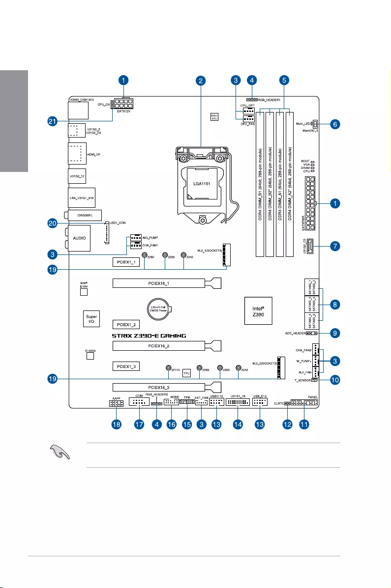
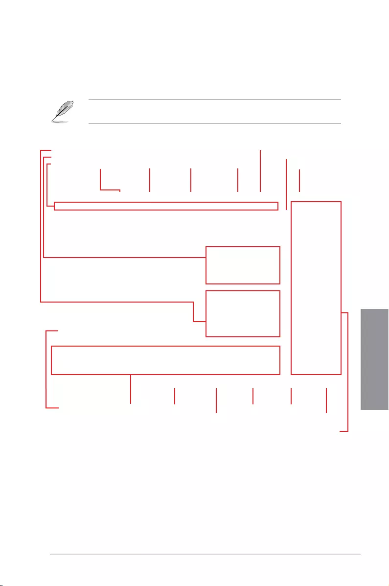
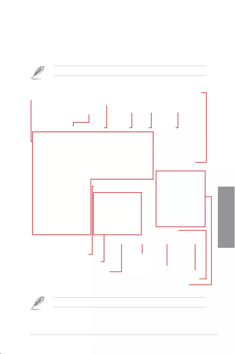
1.1.2 Motherboard layout

ROG STRIX Z390-E GAMING 1-3
Chapter 1
Layout contents
Connectors/Jumpers/Buttons and switches/Slots Page
1. ATXpowerconnectors(24-pinEATXPWR;8-pinEATX12V) 1-19
2. LGA1151CPUSocket 1-4
3. Fanandpumpconnectors(4-pinCPU_FAN;4-pinCPU_OPT;5-pin
EXT_FAN;4-pinW_PUMP+;4-pinAIO_PUMP;4-pinCHA_FAN1-2;4-pin
M.2_FAN)
1-17
4. AURARGBheaders(4-pinRGB_HEADER1-2) 1-22
5. DDR4DIMMslots 1-5
6. MemOK!IIswitch(MemOK!_II) 1-9
7. USB3.1Gen2frontpanelconnector(U31G2_C5) 1-14
8. Intel®Z390SerialATA6Gb/sconnectors(7-pinSATA6G_12;SATA6G_34;
SATA6G_56) 1-13
9. AddressableRGBheader(4-1pinADD_HEADER) 1-23
10. Thermalsensorconnector(2-pinT_SENSOR) 1-16
11. Systempanelconnector(20-3pinPANEL) 1-20
12. ClearRTCRAMjumper(2-pinCLRTC) 1-10
13. USB2.0connectors(10-1pinUSB_E12;USB_1112) 1-16
14. USB3.1Gen1connector(20-1pinU31G1_78) 1-15
15. TPMconnector(14-1pinTPM) 1-18
16. Nodeconnector(12-1pinNODE) 1-18
17. Serialportconnector(10-1pinCOM) 1-24
18. Frontpanelaudioconnector(10-1pinAAFP) 1-14
19. M.2sockets(M.2_1(Socket3);M.2_2(Socket3)) 1-21
20. LEDconnector(8-pinLED1_CON) 1-24
21. CPUOverVoltagejumper(3-pinCPU_OV) 1-11
1-4 Chapter 1: Product Introduction
Chapter 1
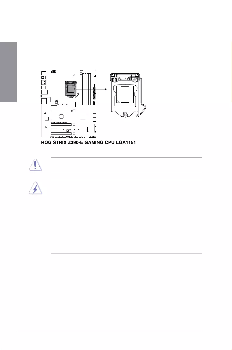
1.1.3 Central Processing Unit (CPU)
ThismotherboardsupportsSocket1151for9th/8thGenIntel®Core™,Pentium®Goldand
Celeron®processors,withmemoryandPCIExpresscontrollersintegratedtosupportdual-
channel(4DIMM)DDR4memoryand16PCIExpress3.0/2.0lanes.
• EnsurethatallpowercablesareunpluggedbeforeinstallingtheCPU.
• Uponpurchaseofthemotherboard,ensurethatthePnPcapisonthesocketand
thesocketcontactsarenotbent.ContactyourretailerimmediatelyifthePnPcap
ismissing,orifyouseeanydamagetothePnPcap/socketcontacts/motherboard
components.ASUSwillshoulderthecostofrepaironlyifthedamageisshipment/
transit-related.
• Keepthecapafterinstallingthemotherboard.ASUSwillprocessReturnMerchandise
Authorization(RMA)requestsonlyifthemotherboardcomeswiththecaponthe
LGA1151socket.
• Theproductwarrantydoesnotcoverdamagetothesocketcontactsresultingfrom
incorrectCPUinstallation/removal,ormisplacement/loss/incorrectremovalofthePnP
cap.
EnsurethatyouinstallthecorrectCPUdesignedforLGA1151socketonly.DONOTinstall
aCPUdesignedforLGA1150,LGA1155,andLGA1156socketsintheLGA1151socket.
ROG STRIX Z390-E GAMING 1-5
Chapter 1
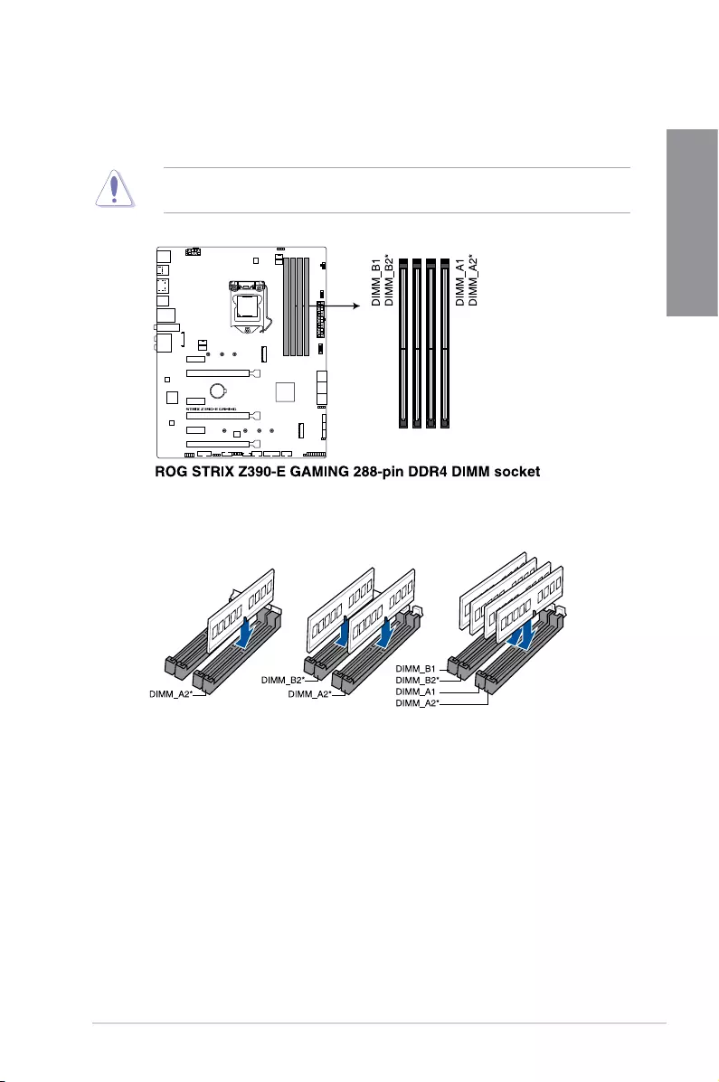
Recommended memory configurations
1.1.4 System memory
ThemotherboardcomeswithfourDoubleDataRate4(DDR4)DualInlineMemoryModules
(DIMM)slots.
ADDR4moduleisnotcheddifferentlyfromaDDR,DDR2,orDDR3module.DONOT
installaDDR,DDR2,orDDR3memorymoduletotheDDR4slot.

1-6 Chapter 1: Product Introduction
Chapter 1
Memory configurations
Youmayinstall2GB,4GB,8GBand16GBunbufferedandnon-ECCDDR4DIMMsinto
theDIMMsockets.
• YoumayinstallvaryingmemorysizesinChannelAandChannelB.Thesystem
mapsthetotalsizeofthelower-sizedchannelforthedual-channelconguration.Any
excessmemoryfromthehigher-sizedchannelisthenmappedforsingle-channel
operation.
• ThismotherboarddoesnotsupportDIMMsmadeupof512Mb(64MB)chipsorless
(MemorychipcapacitycountsinMegabit,8Megabit/Mb=1Megabyte/MB).
• ThedefaultmemoryoperationfrequencyisdependentonitsSerialPresenceDetect
(SPD),whichisthestandardwayofaccessinginformationfromamemorymodule.
Underthedefaultstate,somememorymodulesforoverclockingmayoperateata
lowerfrequencythanthevendor-markedvalue.
• Forsystemstability,useamoreefcientmemorycoolingsystemtosupportafull
memoryload(4DIMMs)oroverclockingcondition.
• AlwaysinstalltheDIMMSwiththesameCASLatency.Foranoptimumcompatibility,
werecommendthatyouinstallmemorymodulesofthesameversionordatacode
(D/C)fromthesamevendor.Checkwiththevendortogetthecorrectmemory
modules.
• VisittheASUSwebsiteforthelatestQVL.
ROG STRIX Z390-E GAMING 1-7
Chapter 1
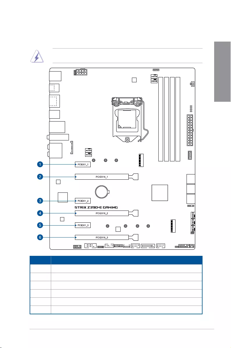
1.1.5 Expansion slots
Unplugthepowercordbeforeaddingorremovingexpansioncards.Failuretodosomay
causeyouphysicalinjuryanddamagemotherboardcomponents.
Slot No. Slot Description
1PCIe3.0x1_1slot
2PCIe3.0x16_1slot
3PCIe3.0x1_2slot
4 PCIe3.0x16_2slot
5 PCIe3.0x1_3slot
6PCIe3.0x16_3slot
1-8 Chapter 1: Product Introduction
Chapter 1
• WerecommendthatyouprovidesufcientpowerwhenrunningCrossFireX™orSLI®
mode.
• ConnectachassisfantothemotherboardconnectorlabeledCHA_FAN1-2when
usingmultiplegraphicscardsforbetterthermalenvironment.
• ThePCIex16_3slotsharesbandwidthwithSATA6G_56.ThePCIex16_3issetatx2
modebydefault.
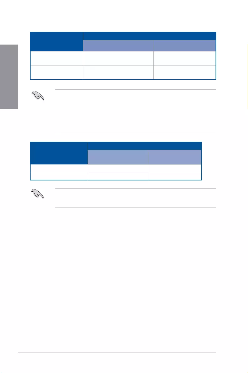
VGA Configuration
PCIe operating mode
PCIEX16_1 PCIEX16_2
SingleVGA/PCIecard x16(RecommendforsingleVGA) N/A
DualVGA/PCIecard x8 x8
• HyperM.2X16seriescardispurchasedseparately.
• EnabletheHyperM.2X16seriescardunderBIOSsettings.
Hyper M.2 X16 card
configuration
PCI Express 3.0 operating mode
PCIEX16_1 PCIEX16_2
2Intel®SSDonCPUsupport —x4+x4
3Intel®SSDonCPUsupport x8+x4+x4 —
ROG STRIX Z390-E GAMING 1-9
Chapter 1
1.1.6 Onboard buttons and switches
Onboardbuttonsandswitchesallowyoutone-tuneperformancewhenworkingonabareor
open-casesystem.Thisisidealforoverclockersandgamerswhocontinuallychangesettings
toenhancesystemperformance.
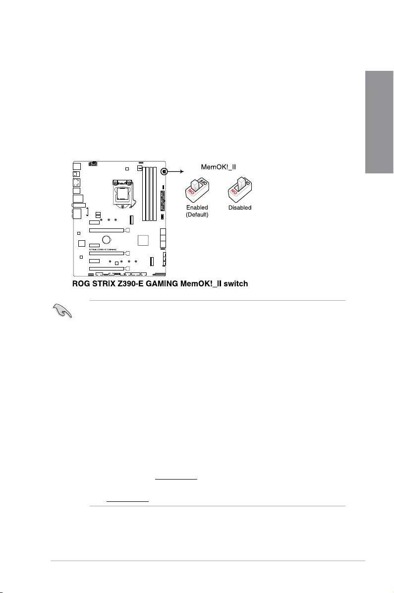
1. MemOK! II switch (MemOK!_II)
InstallingDIMMsthatarenotcompatiblewiththemotherboardmaycausesystem
bootfailure.Theswitchisenabledbydefault,allowingmemoryre-trainingwhenthe
motherboardisunresponsiveduetomemoryproblems.TheMem_LEDwilllightup
whilere-training,andturnoffwhenthere-trainingiscomplete.
• Refertosection1.1.8 Onboard LEDsfortheexactlocationoftheMem_LED.
• TheDRAMLEDalsolightsupwhentheDIMMisnotproperlyinstalled.Turnoffthe
systemandreinstalltheDIMMbeforeusingtheMemOK!IIfunction.
• TheMemOK!IIswitchdoesnotfunctionunderWindows®OSenvironment.
• Duringthetuningprocess,thesystemloadsandtestspretestproles.Ittakesabout
30secondsforthesystemtotestonesetofproles.Ifthetestfails,thesystem
rebootsandteststhenextsetofproles.Thesystemwillrebootmultipletimeswhen
training,oncethesystemhascompletedthetrainingprocesstheMem_LEDwillturn
off,pleaserefrainfromdoinganythingbeforetheMem_LEDturnsoff.
• Duetomemorytuningrequirement,thesystemautomaticallyrebootswheneach
proleistested.
• IfyouturnoffthecomputerandreplaceDIMMsduringthetuningprocess,thesystem
continuesmemorytuningafterturningonthecomputer.Tostopmemorytuning,turn
offthecomputerandunplugthepowercordforabout5–10seconds,thensetthe
MemOK!IIswitchtodisabled.
• EnsuretoreplacetheDIMMswithonesrecommendedintheMemoryQVL(Qualied
VendorsLists)atwww.asus.com.
• WerecommendthatyoudownloadandupdatetothelatestBIOSversionfrom
www.asus.comafterusingtheMemOK!IIfunction.
1-10 Chapter 1: Product Introduction
Chapter 1
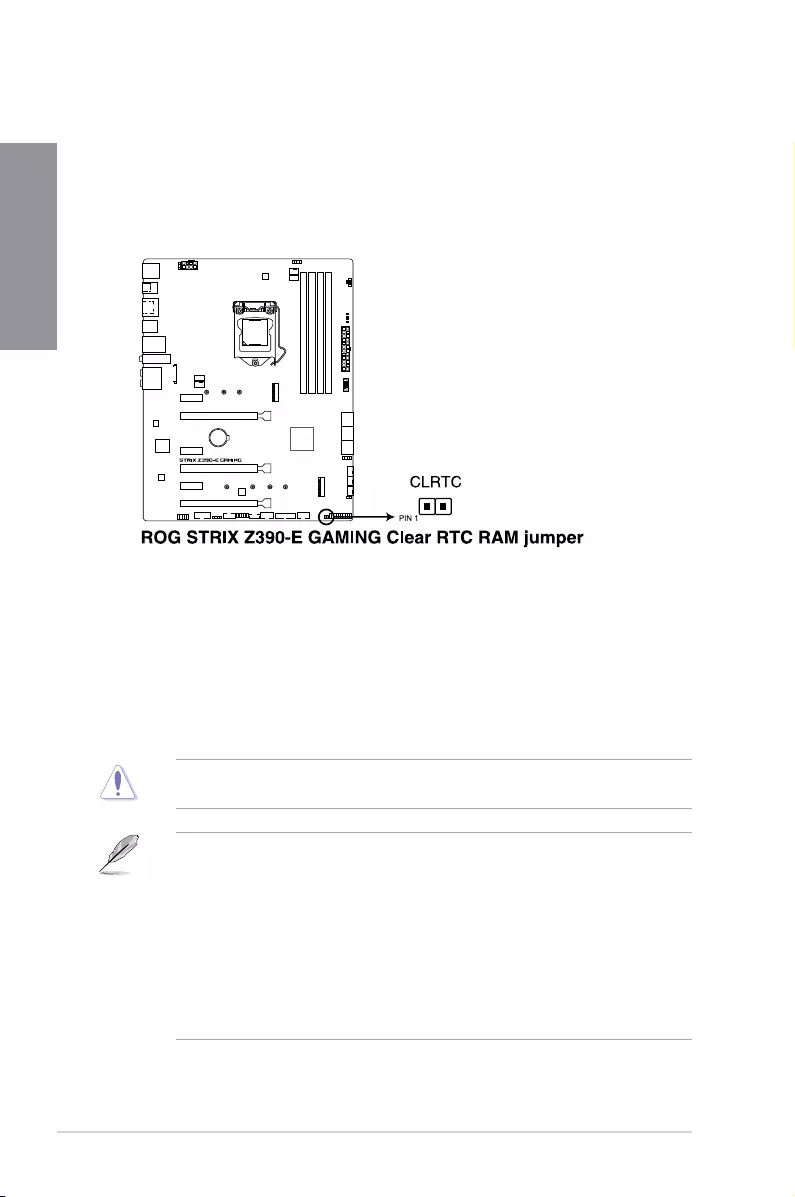
1.1.7 Jumper
1. Clear RTC RAM jumper (2-pin CLRTC)
ThisjumperallowsyoutocleartheRealTimeClock(RTC)RAMinCMOS.Youcan
cleartheCMOSmemoryofdate,time,andsystemsetupparametersbyerasingthe
CMOSRTCRAMdata.TheonboardbuttoncellbatterypowerstheRAMdatain
CMOS,whichincludesystemsetupinformationsuchassystempasswords.
ToerasetheRTCRAM:
1. TurnOFFthecomputerandunplugthepowercord.
2. Short-circuitpin1-2withametalobjectorjumpercapforabout5-10seconds.
3. PlugthepowercordandturnONthecomputer.
4. Holddownthe<Delete>keyduringthebootprocessandenterBIOSsetuptore-enter
data.
ExceptwhenclearingtheRTCRAM,neverplaceametalobjectorjumpercaponthe
CLRTCjumper.Placingametalobjectorjumpercapwillcausesystembootfailure!
• Ifthestepsabovedonothelp,removetheonboardbatteryandplaceametalobject
orjumpercapagaintocleartheCMOSRTCRAMdata.AftertheCMOSclearance,
reinstallthebattery.
• YoudonotneedtocleartheRTCwhenthesystemhangsduetooverclocking.For
systemfailureduetooverclocking,usetheC.P.R.(CPUParameterRecall)feature.
ShutdownandrebootthesystemsotheBIOScanautomaticallyresetparameter
settingstodefaultvalues.
• Duetothechipsetbehavior,ACpoweroffisrequiredtoenableC.P.R.function.You
mustturnoffandturnonthepowersupplyorunplugandplugthepowercordbefore
rebootingthesystem.
ROG STRIX Z390-E GAMING 1-11
Chapter 1
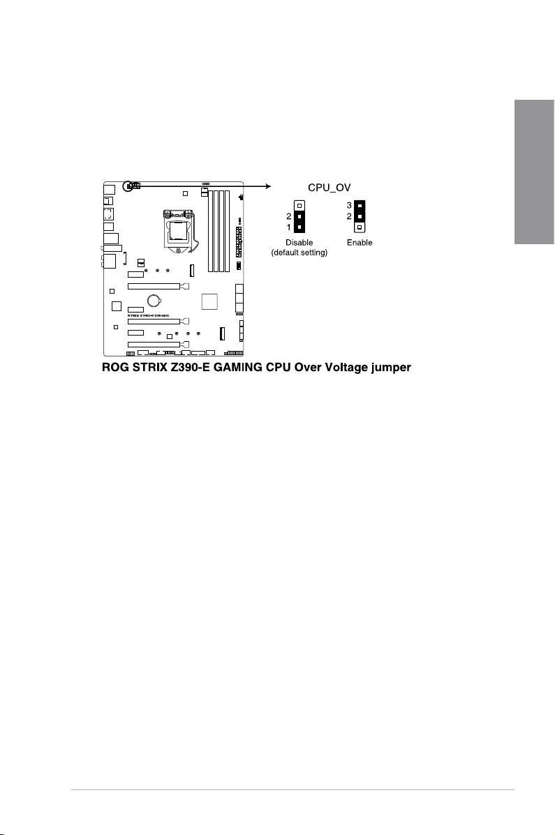
2. CPU Over Voltage jumper (3-pin CPU_OV)
TheCPUOverVoltagejumperallowsyoutosetahigherCPUvoltageforaexible
overclockingsystem,dependingonthetypeoftheinstalledCPU.TogainmoreCPU
voltagesetting,insertthejumpertopins2-3.TogobacktoitsdefaultCPUvoltage
setting,insertthejumpertopins1-2.
1-12 Chapter 1: Product Introduction
Chapter 1
1.1.8 Onboard LEDs
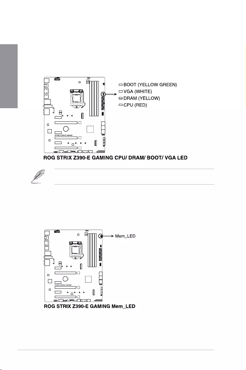
1. Q LEDs (BOOT_LED, VGA_LED, DRAM_LED, CPU_LED)
QLEDscheckkeycomponents(CPU,DRAM,VGAcard,andbootingdevices)in
sequenceduringmotherboardbootingprocess.Ifanerrorisfound,thecorresponding
LEDremainslituntiltheproblemissolved.Thisuser-friendlydesignprovidesan
intuitivewaytolocatetherootproblemwithinseconds.
TheQLEDsprovidethemostprobablecauseofanerrorcodeasastartingpointfor
troubleshooting.Theactualcausemayvaryfromcasetocase.
2. Memory LED (Mem_LED)
TheMem_LEDwilllightupandremainlitwhiletheMemOK!IIfunctionisinuse.When
there-trainingiscomplete,theMem_LEDwillturnoff.
ROG STRIX Z390-E GAMING 1-13
Chapter 1
1.1.9 Internal connectors
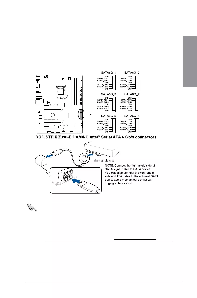
1. Intel® Z390 Serial ATA 6 Gb/s connectors (7-pin SATA6G_12; SATA6G_34;
SATA6G_56)
TheseconnectorsconnecttoSerialATA6Gb/sharddiskdrivesviaSerialATA6Gb/s
signalcables.
IfyouinstalledSerialATAharddiskdrives,youcancreateaRAID0,1,5,and10
congurationwiththeIntel®RapidStorageTechnologythroughtheonboardIntel®
Z390chipset.
• ThePCIex16_3slotsharesbandwidthwithSATA6G_56.ThePCIex16_3issetatx2
modebydefault.
• Theseconnectorsaresetto[AHCI]bydefault.IfyouintendtocreateaSerialATA
RAIDsetusingtheseconnectors,settheSATAModeSelectionitemintheBIOSto
[Intel RST Premium With Intel Optane System Acceleration (RAID)].
• FormoreinformationonconguringyourRAIDsets,pleaserefertotheRAID
Configuration Guidewhichyoucanndathttps://www.asus.com/support.
1-14 Chapter 1: Product Introduction
Chapter 1
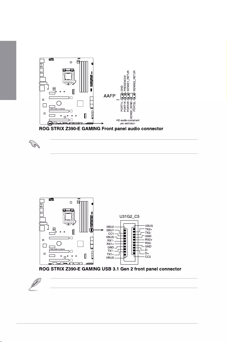
3. USB 3.1 Gen 2 front panel connector (U31G2_C5)
ThisconnectorallowsyoutoconnectaUSB3.1Gen2moduleforadditionalUSB3.1
Gen2ports.ThelatestUSB3.1Gen2connectivityprovidesdatatransferspeedsof
upto10Gbps.
2. Front panel audio connector (10-1 pin AAFP)
Thisconnectorisforachassis-mountedfrontpanelaudioI/Omodulethatsupports
HDAudiostandard.ConnectoneendofthefrontpanelaudioI/Omodulecabletothis
connector.
Werecommendthatyouconnectahigh-denitionfrontpanelaudiomoduletothis
connectortoavailofthemotherboard’shigh-denitionaudiocapability.
TheUSB3.1Gen2moduleispurchasedseparately.
ROG STRIX Z390-E GAMING 1-15
Chapter 1
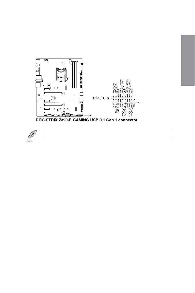
4. USB 3.1 Gen 1 connector (20-1 pin U31G1_78)
ThisconnectorallowsyoutoconnectaUSB3.1Gen1moduleforadditionalUSB
3.1Gen1frontorrearpanelports.WithaninstalledUSB3.1Gen1module,youcan
enjoyallthebenetsofUSB3.1Gen1includingfasterdatatransferspeedsofupto
5Gb/s,fasterchargingtimeforUSB-chargeabledevices,optimizedpowerefciency,
andbackwardcompatibilitywithUSB2.0.
TheUSB3.1Gen1moduleispurchasedseparately.
1-16 Chapter 1: Product Introduction
Chapter 1
Neverconnecta1394cabletotheUSBconnectors.Doingsowilldamagethe
motherboard!
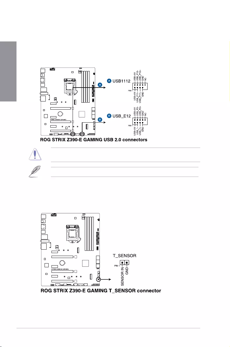
5. USB 2.0 connectors (10-1 pin USB_E12; USB_1112)
TheseconnectorsarefortheUSB2.0ports.ConnecttheUSBmodulecabletothis
connector,theninstallthemoduletoaslotopeningatthebackofthesystemchassis.
ThisUSBconnectorcomplieswithUSB2.0specicationthatsupportsupto480MBps
connectionspeed.
6. Thermal sensor connector (2-pin T_SENSOR)
Thisconnectorisforthethermistorcablethatallowsyoutomonitorthetemperatureof
yourmotherboard’scriticalcomponentsandconnecteddevices.
TheUSB2.0moduleispurchasedseparately.
ROG STRIX Z390-E GAMING 1-17
Chapter 1
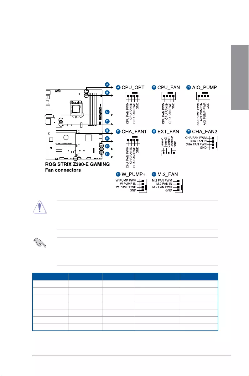
7. Fan and pump connectors (4-pin CPU_FAN; 4-pin CPU_OPT; 5-pin EXT_FAN;
4-pin W_PUMP+; 4-pin AIO_PUMP; 4-pin CHA_FAN1-2; 4-pin M.2_FAN)
Connectthefancablestothefanconnectorsonthemotherboard,ensuringthatthe
blackwireofeachcablematchesthegroundpinoftheconnector.
TheEXT_FANconnectorisonlyforthefanextensioncard.Formoredetailsonthe
fanextensioncard,pleaserefertotheTo install Fan Extension Cardsectioninthis
guide.
Header Max. Current Max. Power Default Speed Shared Control
CPU_FAN 1A 12W Q-FanControlled A
CPU_OPT 1A 12W Q-FanControlled A
CHA_FAN1 1A 12W Q-FanControlled —
CHA_FAN2 1A 12W Q-FanControlled —
AIO_PUMP 1A 12W Full-Speed —
W_PUMP+ 3A 36W Full-Speed —
M.2 1A 12W Q-FanControlled —
• DONOTforgettoconnectthefancablestothefanconnectors.Insufcientairow
insidethesystemmaydamagethemotherboardcomponents.Thesearenotjumpers!
Donotplacejumpercapsonthefanconnectors!
• Ensuretofullyinsertthefancabletothefanconnector.
• TheFANExtensioncardispurchasedseparately.
• W_PUMP+functionsupportdependsonwatercoolingdevice.
• ConnectthefanofyourwatercoolingkittotheW_PUMP+connector.
1-18 Chapter 1: Product Introduction
Chapter 1
Visitwww.asus.comformoreinformationaboutthedevicesandthelatestcompatibilitylist.
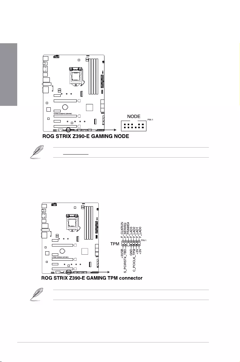
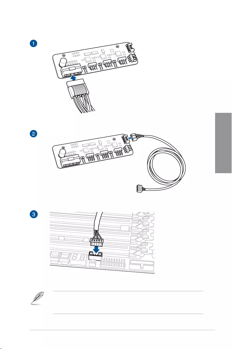
8. Node connector (12-1 pin NODE)
ThisconnectorallowyoutoconnectacompatiblePSUorcontrolacompatiblefan
extensioncard.
9. TPM connector (14-1 pin TPM)
ThisconnectorsupportsaTrustedPlatformModule(TPM)system,whichsecurely
storeskeys,digitalcerticates,passwordsanddata.ATPMsystemalsohelps
enhancenetworksecurity,protectdigitalidentities,andensuresplatformintegrity.
TheTPMmoduleispurchasedseparately.
ROG STRIX Z390-E GAMING 1-19
Chapter 1
• Forafullyconguredsystem,werecommendthatyouuseapowersupplyunit
(PSU)thatcomplieswithATX12VSpecication2.0(orlaterversion)andprovidesa
minimumpowerof350W.
• Donotforgettoconnectthe8-pinEATX12Vpowerplug.Otherwise,thesystemwill
notboot.
• WerecommendthatyouuseaPSUwithahigherpoweroutputwhenconguringa
systemwithmorepower-consumingdevices.Thesystemmaybecomeunstableor
maynotbootupifthepowerisinadequate.
• Ifyouwanttousetwoormorehigh-endPCIex16cards,useaPSUwith1000W
powerorabovetoensurethesystemstability.
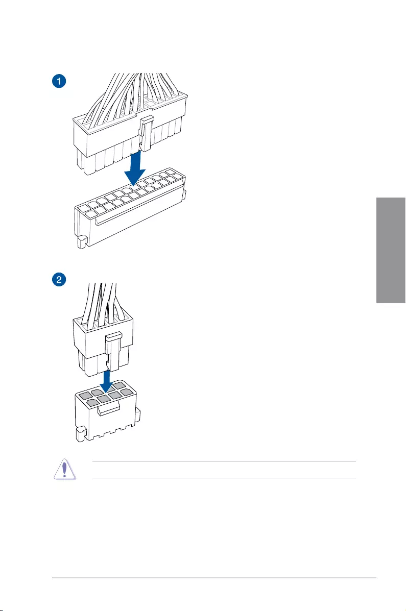
10. ATX power connectors (24-pin EATXPWR; 8-pin EATX12V)
TheseconnectorsareforATXpowersupplyplugs.Thepowersupplyplugsare
designedtottheseconnectorsinonlyoneorientation.Findtheproperorientationand
pushdownrmlyuntiltheconnectorscompletelyt.
1-20 Chapter 1: Product Introduction
Chapter 1
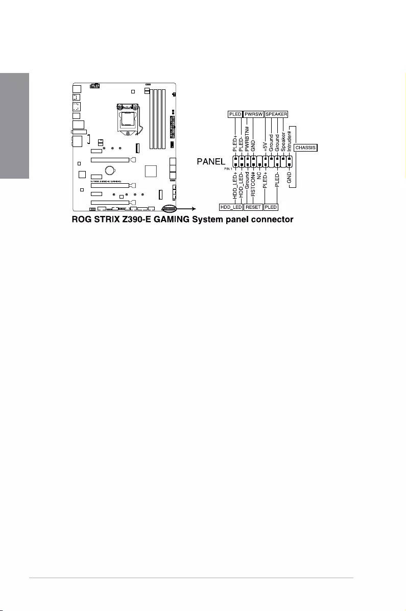
• SystempowerLED(2-pinor3-1pinPLED)
The2-pinor3-1pinconnectorisforthesystempowerLED.Connectthechassis
powerLEDcabletothisconnector.ThesystempowerLEDlightsupwhenyouturnon
thesystempower,andblinkswhenthesystemisinsleepmode.
• HarddiskdriveactivityLED(2-pinHDD_LED)
This2-pinconnectorisfortheHDDActivityLED.ConnecttheHDDActivityLEDcable
tothisconnector.TheHDDLEDlightsuporasheswhendataisreadfromorwritten
totheHDD.
• Systemwarningspeaker(4-pinSPEAKER)
This4-pinconnectorisforthechassis-mountedsystemwarningspeaker.Thespeaker
allowsyoutohearsystembeepsandwarnings.
• ATXpowerbutton/soft-offbutton(2-pinPWRSW)
Thisconnectorisforthesystempowerbutton.Pressingthepowerbuttonturnsthe
systemonorputsthesysteminsleeporsoft-offmodedependingontheoperating
systemsettings.Pressingthepowerswitchformorethanfoursecondswhilethe
systemisONturnsthesystemOFF.
• Resetbutton(2-pinRESET)
This2-pinconnectorisforthechassis-mountedresetbuttonforsystemrebootwithout
turningoffthesystempower.
• Chassisintrusionconnector(2-pinCHASSIS)
Thisconnectorisforachassis-mountedintrusiondetectionsensororswitch.Connect
oneendofthechassisintrusionsensororswitchcabletothisconnector.Thechassis
intrusionsensororswitchsendsahigh-levelsignaltothisconnectorwhenachassis
componentisremovedorreplaced.Thesignalisthengeneratedasachassisintrusion
event.
11. System panel connector (20-3 pin PANEL)
Thisconnectorsupportsseveralchassis-mountedfunctions.
ROG STRIX Z390-E GAMING 1-21
Chapter 1
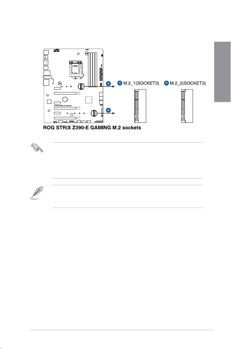
12. M.2sockets(M.2_1(Socket3);M.2_2(Socket3))
ThesesocketsallowyoutoinstallM.2SSDmodules.
• M.2_1socketsupportsPCIe3.0x4andSATAmodeMKeydesignandtype2242/
2260/2280PCIeandSATAstoragedevices.
• M.2_2socketsupportsPCIe3.0x4MKeydesignandtype2242/2260/2280/22110
PCIestoragedevices.
• ThesesocketssupportIRST(Intel®RapidStorageTechnology).
• WhentheM.2_1(Socket3)isoperatinginSATAmode,SATAport2(SATA6G_2)will
bedisabled.
• TheM.2SSDmoduleispurchasedseparately.
1-22 Chapter 1: Product Introduction
Chapter 1
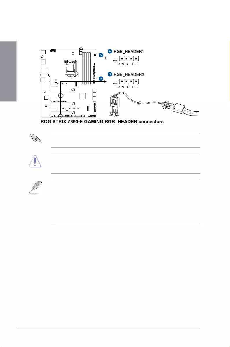
TheRGBheadersupports5050RGBmulti-colorLEDstrips(12V/G/R/B),withamaximum
powerratingof3A(12V),andnolongerthan3m.
Beforeyouinstallorremoveanycomponent,ensurethattheATXpowersupplyisswitched
offorthepowercordisdetachedfromthepowersupply.Failuretodosomaycausesevere
damagetothemotherboard,peripherals,orcomponents.
• ActuallightingandcolorwillvarywithLEDstrips.
• IfyourLEDstripdoesnotlightup,checkiftheRGBLEDextensioncableandthe
RGBLEDstripisconnectedinthecorrectorientation,andthe12Vconnectoris
alignedwiththe12Vheaderonthemotherboard.
• TheLEDstripwillonlylightupwhenthesystemisoperating.
• TheLEDstripsarepurchasedseparately.
13. AURA RGB headers (4-pin RGB_HEADER1-2)
TheseconnectorsareforRGBLEDstrips.
ROG STRIX Z390-E GAMING 1-23
Chapter 1
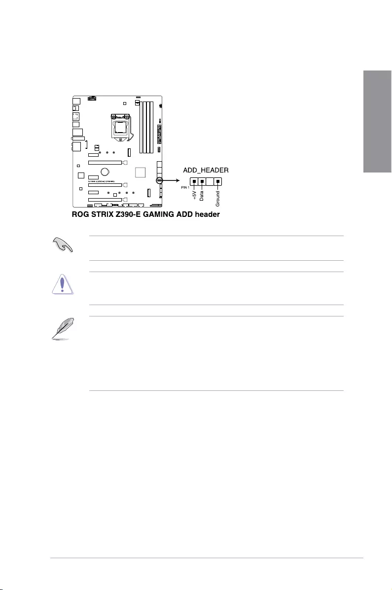
14. Addressable RGB header (4-1 pin ADD_HEADER)
TheseconnectorsareforindividuallyaddressableRGBWS2812BLEDstripsor
WS2812BbasedLEDstrips.
TheaddressableRGBheadersupportsWS2812BaddressableRGBLEDstrips(5V/Data/
Ground),withamaximumpowerratingof3A(5V)andamaximumof120LEDs.
Beforeyouinstallorremoveanycomponent,ensurethattheATXpowersupplyisswitched
offorthepowercordisdetachedfromthepowersupply.Failuretodosomaycausesevere
damagetothemotherboard,peripherals,orcomponents.
• ActuallightingandcolorwillvarywithLEDstrip.
• IfyourLEDstripdoesnotlightup,checkiftheaddressableRGBLEDstripis
connectedinthecorrectorientation,andthe5Vconnectorisalignedwiththe5V
headeronthemotherboard.
• TheaddressableRGBLEDstripwillonlylightupundertheoperatingsystem.
• TheaddressableRGBLEDstripispurchasedseparately.
1-24 Chapter 1: Product Introduction
Chapter 1
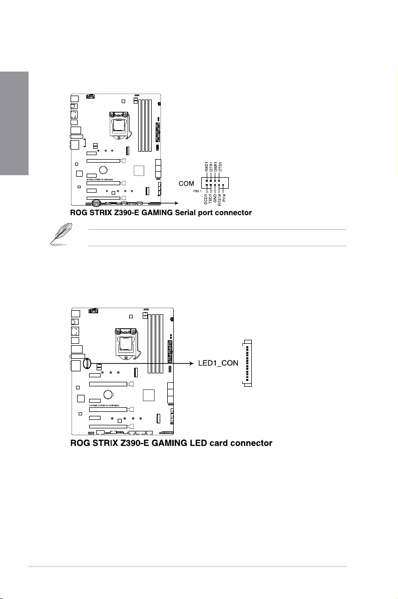
15. Serial port connector (10-1 pin COM)
Thisconnectorisforaserial(COM)port.Connecttheserialportmodulecabletothis
connector,theninstallthemoduletoaslotopeningatthebackofthesystemchassis.
TheCOMmoduleispurchasedseparately.
16. LED connector (8-pin LED1_CON)
ThisLEDconnectorisforconnectingLEDstripsonyourbackI/Ocover.
ROG STRIX Z390-E GAMING 2-1
Chapter 2
2
Basic Installation
2.1 Building your PC system
The diagrams in this section are for reference only. The motherboard layout may vary with
models, but the installation steps are the same for all models.
Chapter 2: Basic Installation
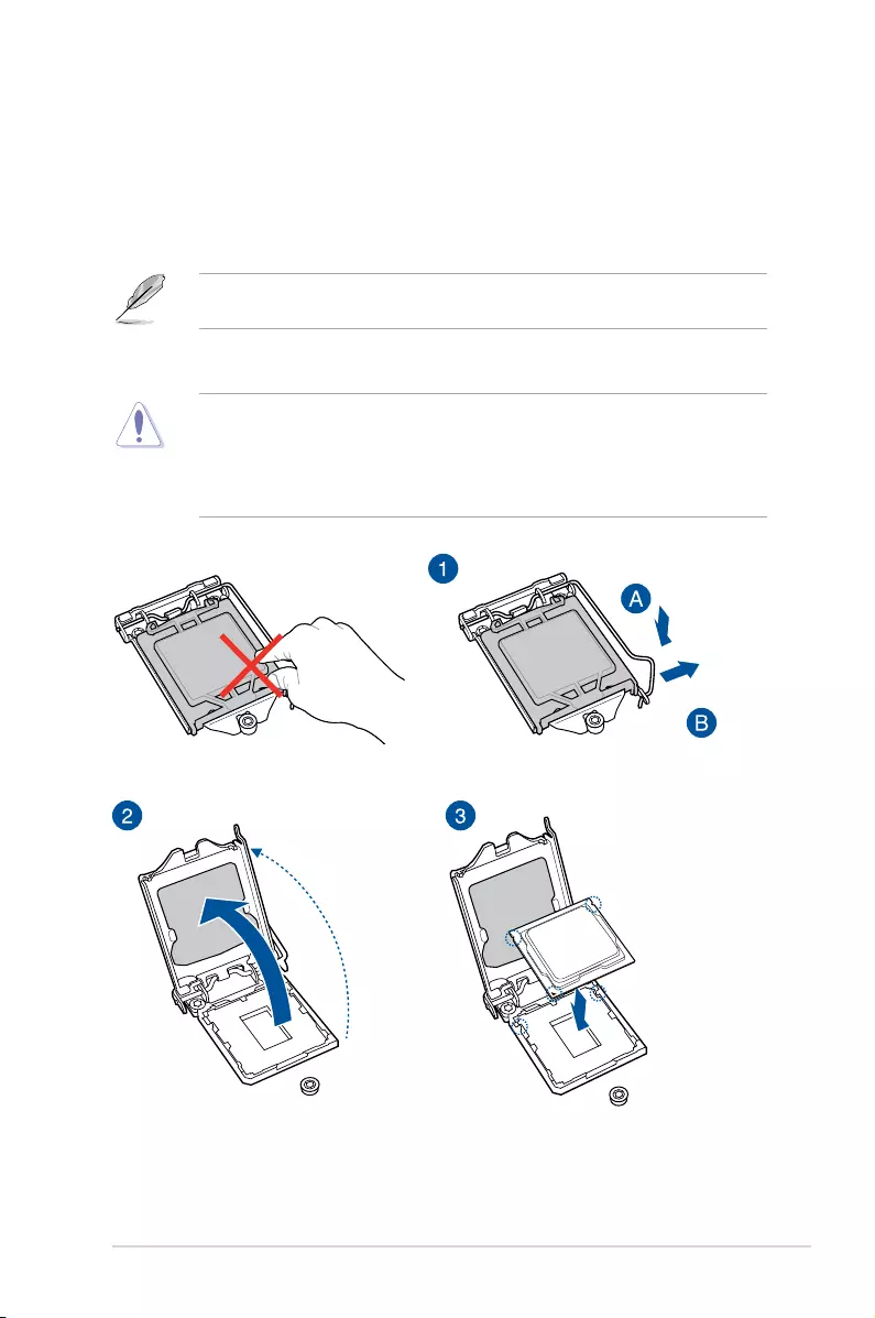
2.1.1 CPU installation
• EnsurethatyouinstallthecorrectCPUdesignedforLGA1151socketonly.DONOT
installaCPUdesignedforLGA1155andLGA1156socketsontheLGA1151socket.
• ASUSwillnotcoverdamagesresultingfromincorrectCPUinstallation/removal,
incorrectCPUorientation/placement,orotherdamagesresultingfromnegligenceby
the user.
2-2 Chapter 2: Basic Installation
Chapter 2
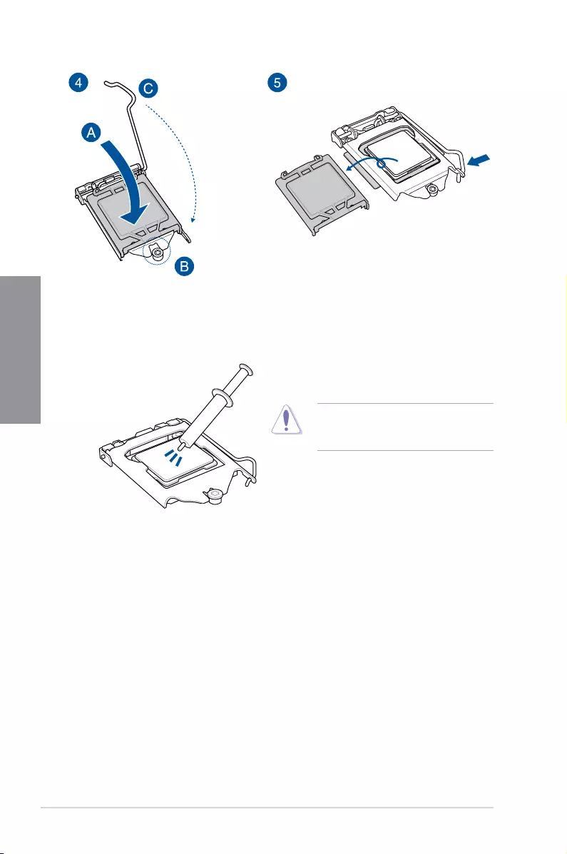
2.1.2 Cooling system installation
ApplyThermalInterfaceMaterialtothe
CPUcoolingsystemandCPUbeforeyou
install the cooling system, if necessary.
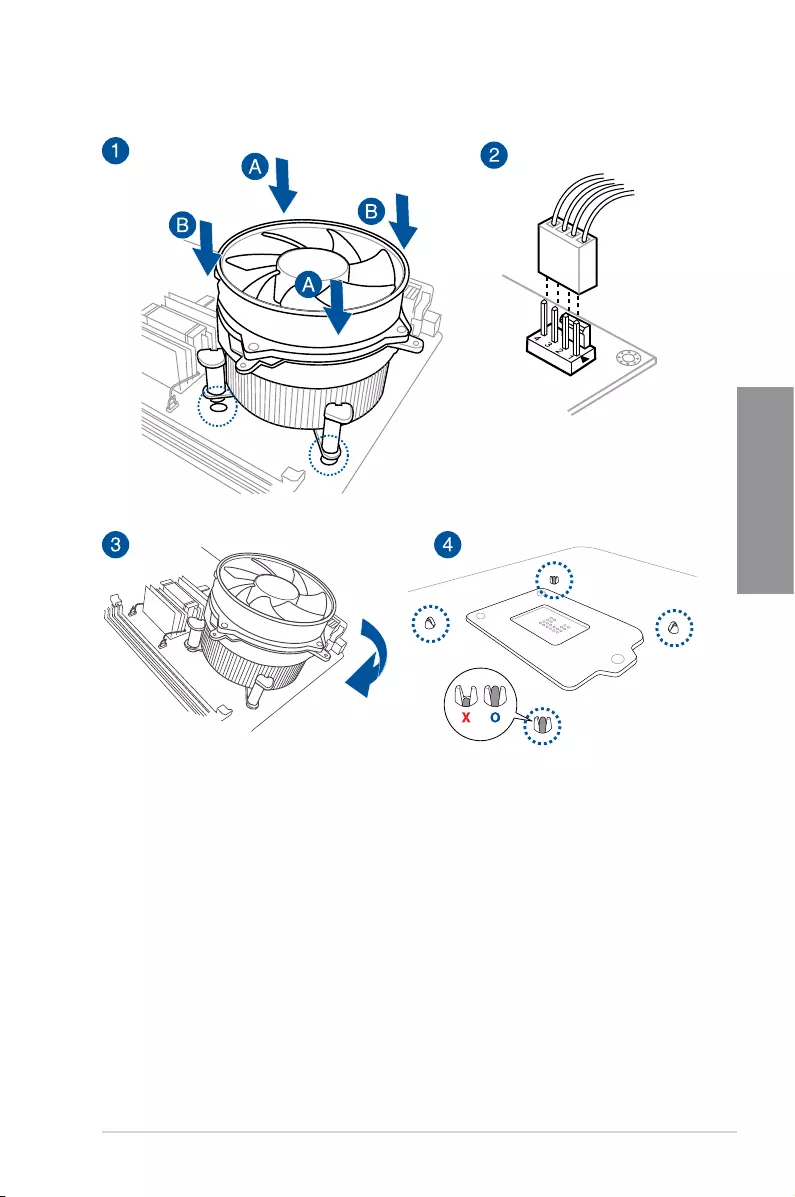
ROG STRIX Z390-E GAMING 2-3
Chapter 2
To install a CPU heatsink and fan assembly
2-4 Chapter 2: Basic Installation
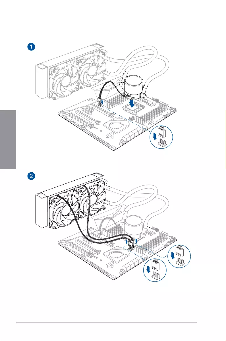
Chapter 2
AIO_PUMP
CPU_OPT
CPU_FAN
To install an AIO cooler
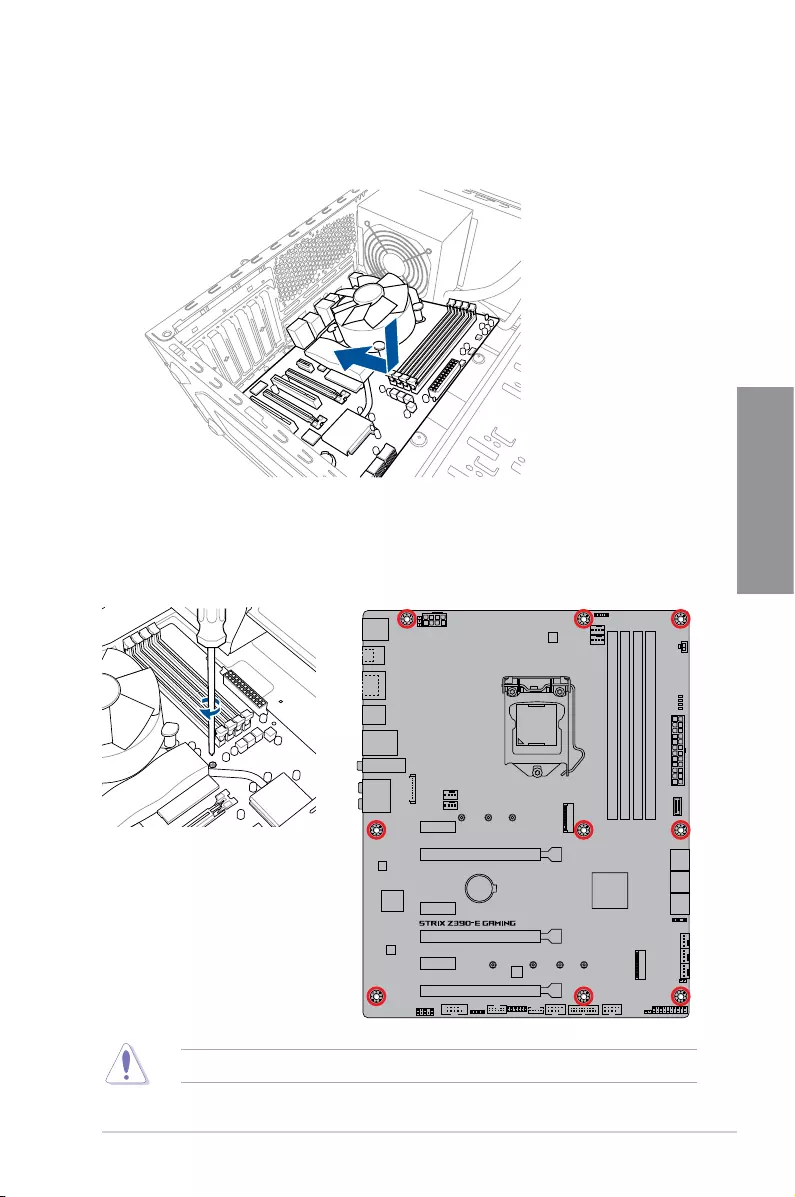
ROG STRIX Z390-E GAMING 2-5
Chapter 2
2. Placenine(9)screwsintotheholesindicatedbycirclestosecurethemotherboardto
the chassis.
DONOTovertightenthescrews!Doingsocandamagethemotherboard.
1. Placethemotherboardintothechassis,ensuringthatitsrearI/Oportsarealignedto
thechassis’rearI/Opanel.
2.1.3 Motherboard installation
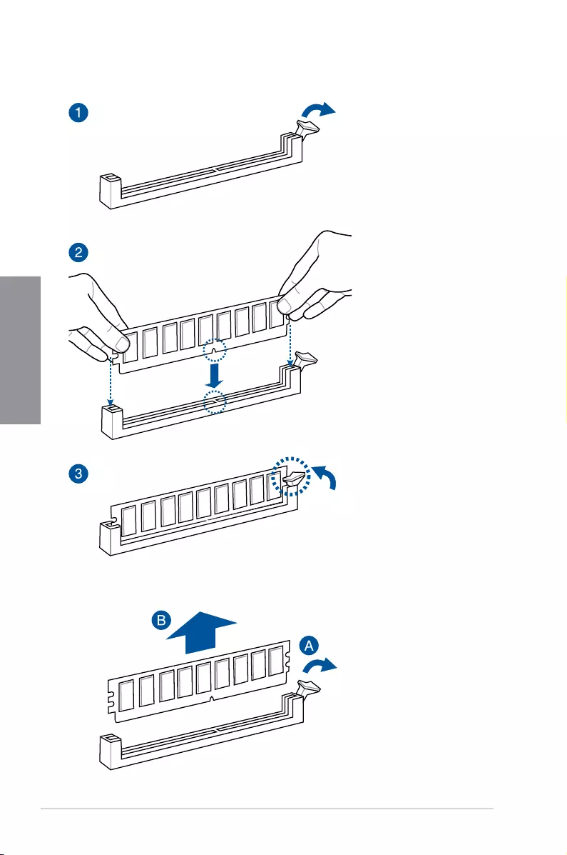
2-6 Chapter 2: Basic Installation
Chapter 2
2.1.4 DIMM installation
To remove a DIMM
ROG STRIX Z390-E GAMING 2-7
Chapter 2
2.1.5 ATX power connection
Ensuretoconnectthe8-pinpowerplug,orconnectboththe8-pinand4-pinpowerplugs.
2-8 Chapter 2: Basic Installation
Chapter 2
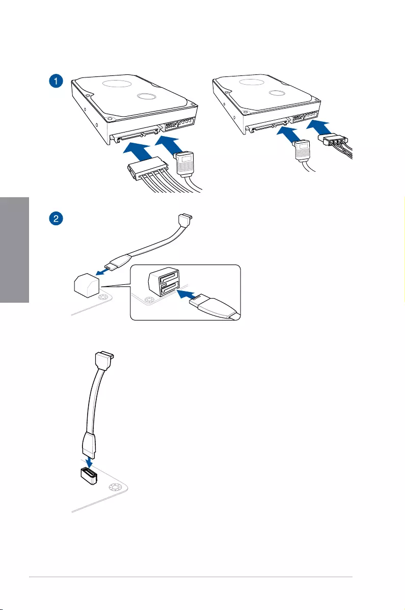
2.1.6 SATA device connection
OR
OR
ROG STRIX Z390-E GAMING 2-9
Chapter 2
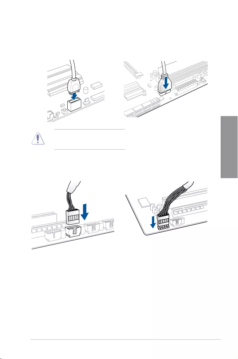
2.1.7 Front I/O connector
USB 3.1 Gen 2
To install USB 3.1 Gen 2 connector
Thisconnectorwillonlytinone
orientation.Pushtheconnectoruntilit
clicksintoplace.
USB 2.0
AAFP
To install USB 2.0 connector To install front panel audio connector
USB 3.1 Gen 1
To install USB 3.1 Gen 1 connector
2-10 Chapter 2: Basic Installation
Chapter 2
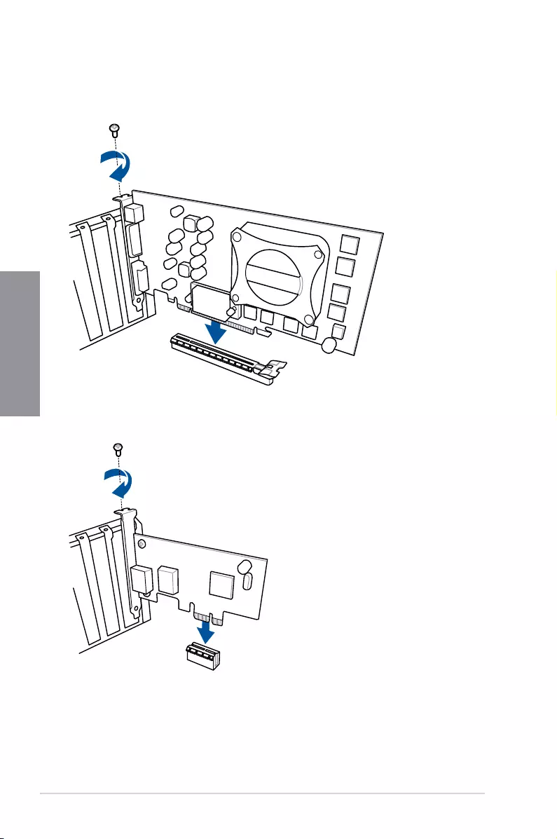
2.1.8 Expansion card installation
To install PCIe x16 cards
To install PCIe x1 cards
ROG STRIX Z390-E GAMING 2-11
Chapter 2
To install FAN EXTENSION CARD
• Theillustrationsinthissectionareforreferenceonly.Themotherboardlayoutmay
vary with models, but the installation steps are the same for all models.
• TheFANExtensioncardispurchasedseparately.
2-12 Chapter 2: Basic Installation
Chapter 2
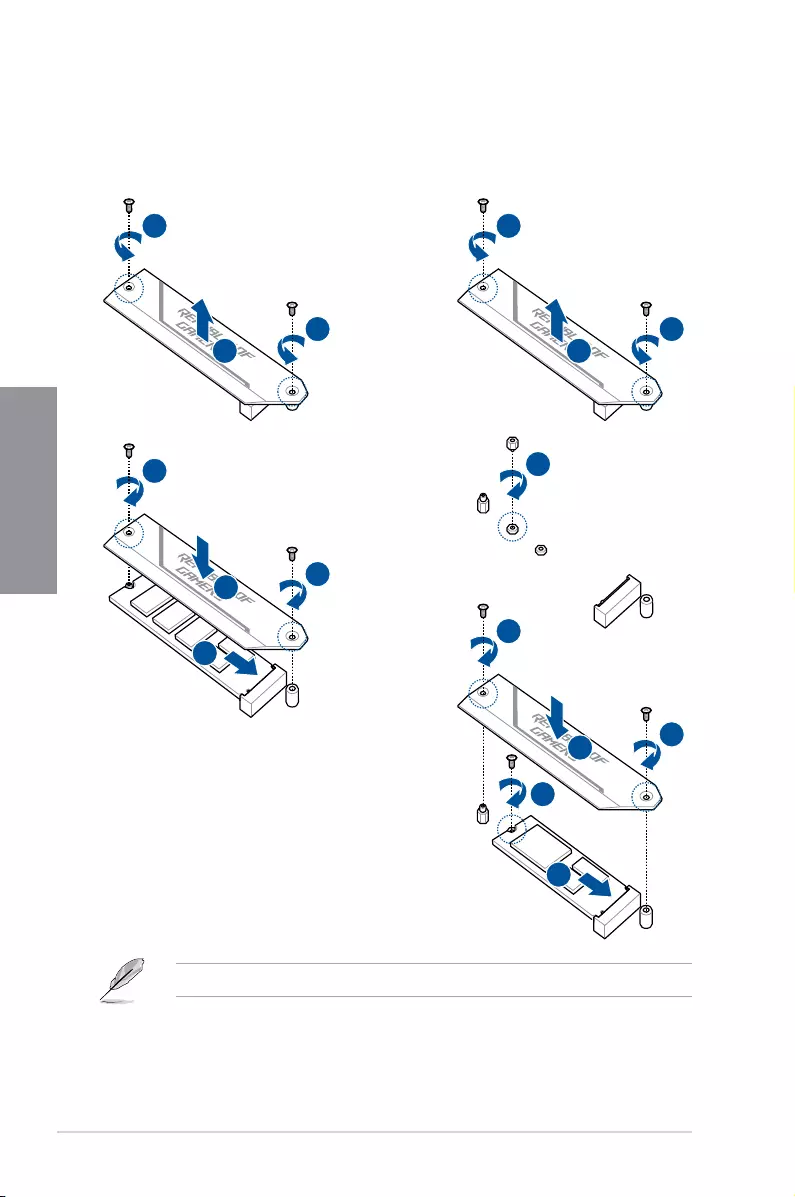
2.1.9 M.2 installation
1
2
1
3
5
5
4
1
2
1
3
4
7
5
7
6
For type 2280 M.2 on M.2_1 socket
or 22110 M.2 on M.2_2 socket
For type 2260 / 2242 M.2 on M.2_1 socket
or 2260 / 2242 / 2280 M.2 on M.2_2 socket
TheM.2ispurchasedseparately.
ROG STRIX Z390-E GAMING 2-13
Chapter 2
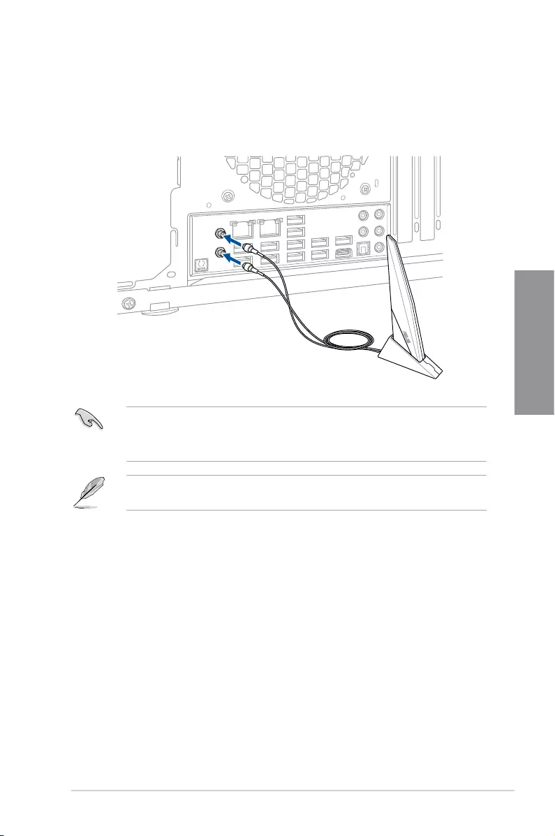
2.1.10 Wi-Fi antenna installation
Installing the ASUS 2×2 dual band W-Fi antenna
ConnectthebundledASUS2×2dualbandWi-FiantennaconnectortotheWi-Fiportsatthe
backofthechassis.
• EnsurethattheASUS2×2dualbandWi-FiantennaissecurelyinstalledtotheWi-Fi
ports.
• Ensurethattheantennaisatleast20cmawayfromallpersons.
Theillustrationaboveisforreferenceonly.TheI/Oportlayoutmayvarywithmodels,but
theWi-Fiantennainstallationprocedureisthesameforallmodels.
2-14 Chapter 2: Basic Installation
Chapter 2
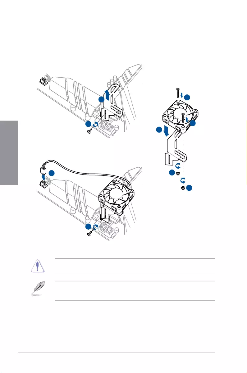
2.1.11 ASUS fan holder installation
To install the ASUS fan holder and fan
Whenusinghighperformancesettingswhilstoverclocking,ensuretoinstallthebundledfan
ontotheMOSfanholder.
• Youmayinstall12V(1A,12W),40mmx40mmfans.
• Ensuretotheusethebundledscrewsthatcamewithyouraccessory.
1
2
5
3
4
4
5
6
7
ROG STRIX Z390-E GAMING 2-15
Chapter 2
2.2 Motherboard rear and audio connections
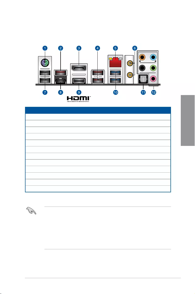
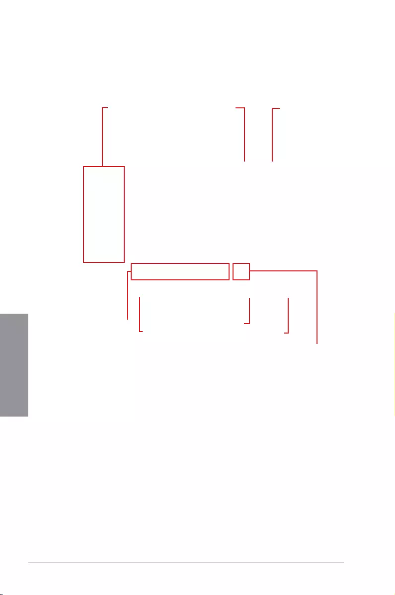
2.2.1 Rear I/O connection
* and ** : Refer to the tables on the next page for LAN port LEDs, and audio port definitions.
Rear panel connectors
1. PS/2mouse/keyboardcomboport
2. USB3.1Gen2Type-Aport3
3. DisplayPort
4. USB3.1Gen2Type-Aports1and2
5. LAN(RJ-45)port*
6. Wi-Fi802.11a/b/g/n/ac,BluetoothV5.0
7. USB2.0Type-Aports13andE3
8. USB3.1Gen2Type-C™portC4
9. HDMIport
10. Intel® USB3.1Gen1ports9and10
11. OpticalS/PDIFOUTport
12. AudioI/Oports**
• USB3.1Gen1/Gen2devicescanonlybeusedasdatastorageonly.
• Westronglyrecommendthatyouconnectyourdevicestoportswithmatchingdata
transferrate.PleaseconnectyourUSB3.1Gen1devicestoUSB3.1Gen1portsand
yourUSB3.1Gen2devicestoUSB3.1Gen2portsforfasterandbetterperformance
for your devices.
• DuetothedesignoftheIntelchipset,allUSBdevicesconnectedtotheUSB3.1Gen
1portsarecontrolledbythexHCIcontroller.SomelegacyUSBdevicesmustupdate
theirrmwareforbettercompatibility.
2-16 Chapter 2: Basic Installation
Chapter 2
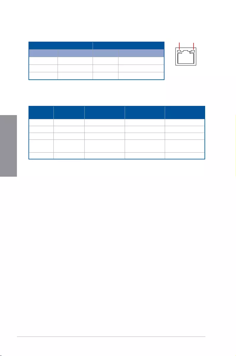
* LAN ports LED indications SPEED
LED
ACT/LINK
LED
LAN port
Activity Link LED Speed LED
Status Description Status Description
OFF Nolink OFF 10Mbpsconnection
ORANGE Linked ORANGE 100Mbpsconnection
BLINKING Dataactivity GREEN 1Gbpsconnection
** Audio 2, 4, 5.1 or 7.1-channel configuration
Port Headset
2-channel 4-channel 5.1-channel 7.1-channel
LightBlue LineIn LineIn LineIn SideSpeakerOut
Lime LineOut FrontSpeakerOut FrontSpeakerOut FrontSpeakerOut
Pink MicIn MicIn MicIn MicIn
Orange – – Center/Sub
woofer
Center/Sub
woofer
Black –RearSpeakerOut RearSpeakerOut RearSpeakerOut
ROG STRIX Z390-E GAMING 2-17
Chapter 2
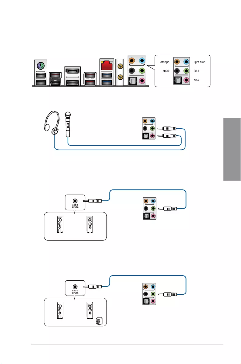
2.2.2 Audio I/O connections
Audio I/O ports
Connect to Headphone and Mic
Connect to Stereo Speakers
Connect to 2-channel Speakers
2-18 Chapter 2: Basic Installation
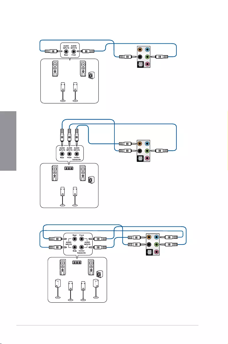
Chapter 2
Connect to 4-channel Speakers
Connect to 5.1-channel Speakers
Connect to 7.1-channel Speakers
ROG STRIX Z390-E GAMING 2-19
Chapter 2
2.3 Starting up for the first time
1. Aftermakingalltheconnections,replacethesystemcasecover.
2. Ensurethatallswitchesareoff.
3. Connectthepowercordtothepowerconnectoratthebackofthesystemchassis.
4. Connectthepowercordtoapoweroutletthatisequippedwithasurgeprotector.
5. Turnonthedevicesinthefollowingorder:
a. Monitor
b. Externalstoragedevices(startingwiththelastdeviceonthechain)
c. Systempower
6. Afterapplyingpower,thesystempowerLEDonthesystemfrontpanelcaselightsup.
ForsystemswithATXpowersupplies,thesystemLEDlightsupwhenyoupressthe
ATXpowerbutton.Ifyourmonitorcomplieswiththe“green”standardsorifithasa
“powerstandby”feature,themonitorLEDmaylightuporchangefromorangetogreen
afterthesystemLEDturnson.
Thesystemthenrunsthepower-onselftests(POST).Whilethetestsarerunning,the
BIOSbeeps(refertotheBIOSbeepcodestable)oradditionalmessagesappearon
thescreen.Ifyoudonotseeanythingwithin30secondsfromthetimeyouturnedon
thepower,thesystemmayhavefailedapower-ontest.Checkthejumpersettingsand
connections or call your retailer for assistance.
BIOS Beep Description
Oneshortbeep
VGAdetected
Quickbootsettodisabled
Nokeyboarddetected
Onecontinuousbeepfollowedbytwo
shortbeepsthenapause(repeated) Nomemorydetected
Onecontinuousbeepfollowedbythree
short beeps NoVGAdetected
Onecontinuousbeepfollowedbyfour
short beeps Hardware component failure
7. Atpoweron,holddownthe<Delete>keytoentertheBIOSSetup.Followthe
instructionsinChapter3.
2.4 Turning off the computer
WhilethesystemisON,pressthepowerbuttonforlessthanfoursecondstoputthesystem
onsleepmodeorsoft-offmode,dependingontheBIOSsetting.Pressthepowerbutton
formorethanfoursecondstoletthesystementerthesoft-offmoderegardlessoftheBIOS
setting.

2-20 Chapter 2: Basic Installation
Chapter 2
ROG STRIX Z390-E GAMING 3-1
Chapter 3
3
BIOS Setup
Chapter 3: BIOS Setup
3.1 Knowing BIOS
The new ASUS UEFI BIOS is a Unied Extensible Interface that complies with UEFI
architecture, offering a user-friendly interface that goes beyond the traditional keyboard-
only BIOS controls to enable a more exible and convenient mouse input. You can easily
navigate the new UEFI BIOS with the same smoothness as your operating system. The
term “BIOS” in this user manual refers to “UEFI BIOS” unless otherwise specied.
BIOS (Basic Input and Output System) stores system hardware settings such as storage
device conguration, overclocking settings, advanced power management, and boot
device conguration that are needed for system startup in the motherboard CMOS. In
normal circumstances, the default BIOS settings apply to most conditions to ensure
optimal performance. DO NOT change the default BIOS settings except in the following
circumstances:
• An error message appears on the screen during the system bootup and requests you to
run the BIOS Setup.
• You have installed a new system component that requires further BIOS settings or
update.
Inappropriate BIOS settings may result to instability or boot failure. We strongly
recommend that you change the BIOS settings only with the help of a trained service
personnel.
• When downloading or updating the BIOS le, rename it as SZ390E.CAP for this
motherboard.
• BIOS settings and options may vary due to different BIOS release versions. Please
refer to the latest BIOS version for settings and options.

3-2 Chapter 3: BIOS Setup
Chapter 3
• The BIOS setup screens shown in this section are for reference purposes only, and
may not exactly match what you see on your screen.
• Ensure that a USB mouse is connected to your motherboard if you want to use the
mouse to control the BIOS setup program.
• If the system becomes unstable after changing any BIOS setting, load the default
settings to ensure system compatibility and stability. Select the Load Optimized
Defaults item under the Exit menu or press hotkey <F5>. See section 3.10 Exit Menu
for details.
• If the system fails to boot after changing any BIOS setting, try to clear the CMOS and
reset the motherboard to the default value. See section 1.1.6 Onboard buttons and
switches for information on how to erase the RTC RAM via the Clear CMOS button.
• The BIOS setup program does not support the Bluetooth devices.
Please visit ASUS website for the detailed BIOS content manual.
BIOS menu screen
The BIOS Setup program can be used under two modes: EZ Mode and Advanced Mode.
You can change modes from Setup Mode in Boot menu or by pressing the <F7> hotkey.
3.2 BIOS setup program
Use the BIOS Setup to update the BIOS or congure its parameters. The BIOS screen
include navigation keys and brief onscreen help to guide you in using the BIOS Setup
program.
Entering BIOS at startup
To enter BIOS Setup at startup, press <Delete> or <F2> during the Power-On Self Test
(POST). If you do not press <Delete> or <F2>, POST continues with its routines.
Entering BIOS Setup after POST
To enter BIOS Setup after POST:
• Press <Ctrl>+<Alt>+<Delete> simultaneously.
• Press the reset button on the system chassis.
• Press the power button to turn the system off then back on. Do this option only if you
failed to enter BIOS Setup using the rst two options.
After doing either of the three options, press <Delete> key to enter BIOS.
ROG STRIX Z390-E GAMING 3-3
Chapter 3
3.2.1 Advanced Mode
The Advanced Mode provides advanced options for experienced end-users to congure
the BIOS settings. The gure below shows an example of the Advanced Mode. Refer to the
following sections for the detailed congurations.
The default screen for entering the BIOS setup program can be changed. Refer to the
Setup Mode item in section Boot menu for details.
Menu items General help
Menu bar Language Qfan Control(F6) AI OC Guide(F11)
MyFavorite(F3) AURA ON/OFF(F4)
Search(F9)
Scroll bar
Pop-up Menu
Configuration fields
Last modified settings Go back to EZ Mode
EZ Tuning Wizard
Hot Keys
Displays a quick overview of the
system status and prediction
Search on the FAQ

3-4 Chapter 3: BIOS Setup
Chapter 3
Menu bar
The menu bar on top of the screen has the following main items:
My Favorites For saving the frequently-used system settings and conguration.
Main For changing the basic system conguration
Ai Tweaker For changing the overclocking settings
Advanced For changing the advanced system settings
Monitor For displaying the system temperature, power status, and changing
the fan settings.
Boot For changing the system boot conguration
Tool For conguring options for special functions
Exit For selecting the exit options and loading default settings
Menu items
The highlighted item on the menu bar displays the specic items for that menu. For example,
selecting Main shows the Main menu items.
The other items (My Favorites, Ai Tweaker, Advanced, Monitor, Boot, Tool, and Exit) on the
menu bar have their respective menu items.
Submenu items
A greater than sign (>) before each item on any menu screen means that the item has a
submenu. To display the submenu, select the item and press <Enter>.
Language
This button above the menu bar contains the languages that you can select for your BIOS.
Click this button to select the language that you want to display in your BIOS screen.
My Favorites(F3)
This button above the menu bar shows all BIOS items in a Tree Map setup. Select frequently-
used BIOS settings and save it to MyFavorites menu.
Refer to section 3.3 My Favorites for more information.
Q-Fan Control(F6)
This button above the menu bar displays the current settings of your fans. Use this button to
manually tweak the fans to your desired settings.
Refer to section 3.2.3 QFan Control for more information.
AI OC Guide(F11)
This button above the menu bar allows you to view the descriptions of AI overclocking and
enable it.
• Refer to section 3.2.4 AI OC Guide for more information.
• This function is only enabled when using an unlocked CPU.
ROG STRIX Z390-E GAMING 3-5
Chapter 3
Search (F9)
This button allows you to search for BIOS items by entering its name, enter the item name to
nd the related item listing.
AURA (F4)
This button allows you to turn the RGB LED lighting or functional LED on or off.
[All On]: All LEDs (Aura or Functional) will be enabled.
[Aura Only]: Aura LEDs will be enabled and functional LEDs will be disabled.
[Aura Off]: Aura LEDs will be disabled, however functional LEDs will still be enabled.
[Stealth Mode]: All LEDs (Aura and Functional) will be disabled.
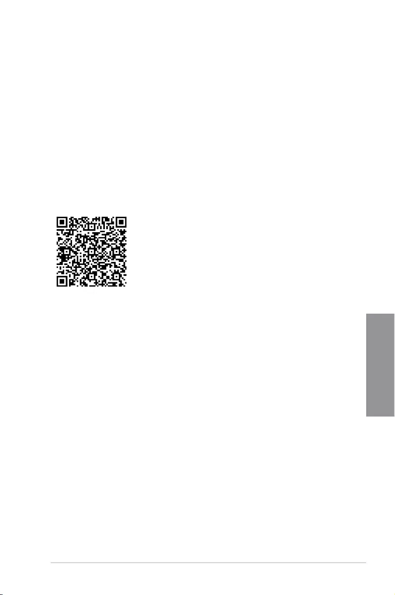
Search on FAQ
Move your mouse over this button to show a QR code, scan this QR code on your mobile
device to connect to the BIOS FAQ web page of the ASUS support website. You can also
scan the following QR code:
Scroll bar
A scroll bar appears on the right side of a menu screen when there are items that do not t
on the screen. Press the Up/Down arrow keys or <Page Up> / <Page Down> keys to display
the other items on the screen.
General help
At the bottom of the menu screen is a brief description of the selected item. Use <F12> key
to capture the BIOS screen and save it to the removable storage device.
Configuration fields
These elds show the values for the menu items. If an item is user-congurable, you can
change the value of the eld opposite the item. You cannot select an item that is not user-
congurable.
A congurable eld is highlighted when selected. To change the value of a eld, select it and
press <Enter> to display a list of options.
Hot keys
This button contains the navigation keys for the BIOS setup program. Use the navigation
keys to select items in the menu and change the settings.

3-6 Chapter 3: BIOS Setup
Chapter 3
EZ Tuning Wizard
This button above the menu bar allows you to view and congure the RAID settings of your
system.
Refer to section 3.2.5 EZ Tuning Wizard for more information.
Last Modified button
This button shows the items that you last modied and saved in BIOS Setup.
ROG STRIX Z390-E GAMING 3-7
Chapter 3
3.2.2 EZ Mode
The EZ Mode provides you an overview of the basic system information, and allows you to
select the display language, system performance, mode and boot device priority. To access
the Advanced Mode, select Advanced Mode or press the <F7> hotkey for the advanced
BIOS settings.
To switch from Advanced Mode to EZ Mode, click EZ Mode(F7) or press the <F7> hotkey.
The boot device options vary depending on the devices you installed to the system.
Selects the display language
of the BIOS setup program
Displays a quick overview
of the system status
Displays the system properties of the selected mode.
Click < or > to switch modes
Loads optimized
default settings
Displays the CPU Fan’s speed. Click
the button to manually tune the fans
Enables or disables the SATA RAID mode
for Intel Rapid Storage Technology Saves the changes
and resets the system
Click to display boot devices
Selects the boot device priority
Click to go to Advanced mode
Search on the FAQ
Search(F9)AI OC Guide(F11)
EZ Tuning Wizard
AURA ON/OFF(F4)
3-8 Chapter 3: BIOS Setup
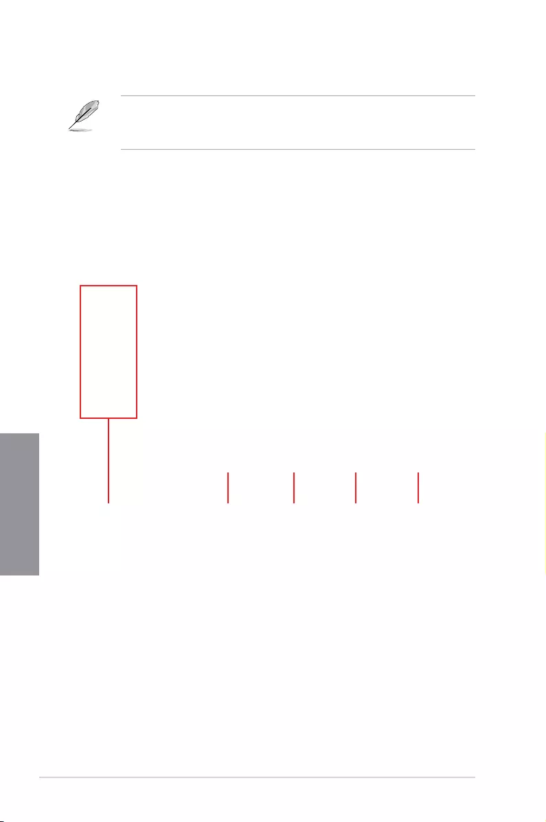
Chapter 3
Click to select a fan to be
configured Click to activate
PWM Mode
Click to undo the
changes
Click to apply the fan setting
Click to go back to main menu
Select a profile to
apply to your fans
Click to activate DC Mode
Select to manually configure
your fans
3.2.3 Q-Fan Control
The QFan Control allows you to set a fan prole or manually congure the operating speed of
your CPU and chassis fans.

ROG STRIX Z390-E GAMING 3-9
Chapter 3
Configuring fans manually
Select Manual from the list of proles to manually congure your fans’ operating speed.
To congure your fans:
1. Select the fan that you want to congure and to view its current status.
2. Click and drag the speed points to adjust the fans’ operating speed.
3. Click Apply to save the changes then click Exit (ESC).
Speed points Select to manually
configure your fans
3-10 Chapter 3: BIOS Setup
Chapter 3
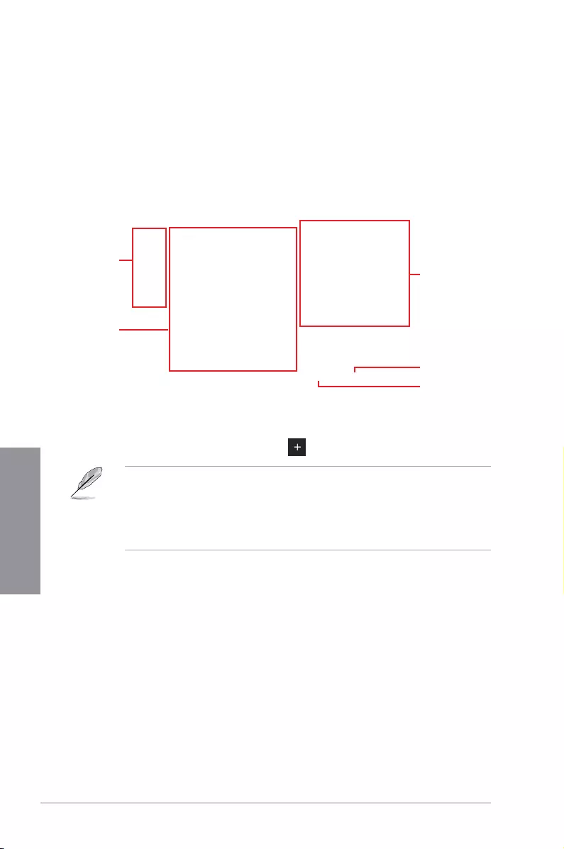
3.2.4 AI OC Guide
• The screenshot shown in this section is for reference purposes only, and may not
exactly match what you see on your screen.
• This function is only enabled when using an unlocked CPU.
The AI OC Guide allows you to enable the Ai Overclocking feature, or view a quick guide
of the Ai Overclocking feature which highlights the recommended setup procedure and
descriptions of the AI Overclocking.
Clicking on Enable AI will enable Ai Overclocking.
Click to view
the next topic in
the quick guide
Click to view the
previous topic in the
quick guide
Quick guide topics Click to go back
to main menu
Click to enable AI
Overclocking

ROG STRIX Z390-E GAMING 3-11
Chapter 3
3.2.5 EZ Tuning Wizard
EZ Tuning Wizard allows you to easily set RAID in your system using this feature.
Creating RAID
To create RAID:
1. Click EZ Tuning Wizard from the BIOS screen to open EZ Tuning Wizard screen.
2. Click Yes
to enable RAID.
• Ensure that your HDDs have no existing RAID volumes.
• Ensure to connect your HDDs to Intel® SATA connectors.
3. Select the port that you want to set to [RAID] mode, PCIE or SATA, then click Next.

3-12 Chapter 3: BIOS Setup
Chapter 3
5. After selecting the type of RAID, click Next then click Yes to continue the RAID setup.
6. After the RAID setup is done, click Yes to exit the setup then click OK to reset your
system.
You can only select Easy Backup (RAID 10) if you connect four (4) HDDs.
b. For Super Speed, click Next then select from Super Speed (RAID 0) or Super
Speed (RAID 5).
a. For Easy Backup, click Next then select from Easy Backup (RAID 1) or Easy
Backup (RAID 10).
4. Select the type of storage for your RAID, Easy Backup or Super Speed, then click
Next.

ROG STRIX Z390-E GAMING 3-13
Chapter 3
3.3 My Favorites
My Favorites is your personal space where you can easily save and access your favorite
BIOS items.
My Favorites comes with several performance, power saving, and fast boot related items by
default. You can personalize this screen by adding or removing items.
3-14 Chapter 3: BIOS Setup
Chapter 3
Adding items to My Favorites
To add BIOS items:
1. Press <F3> on your keyboard or click MyFavorites(F3) from the BIOS screen to open
Setup Tree Map screen.
2. On the Setup Tree Map screen, select the BIOS items that you want to save in My
Favorites screen.
3. Select an item from main menu panel, then click the submenu that you want to save as
favorite from the submenu panel and click or press <Enter> on your keyboard.
You cannot add the following items to My Favorite items:
• Items with submenu options
• User-managed items such as language and boot order
• Conguration items such as Memory SPD Information, system time and date.
4. Click Exit (ESC) or press <Esc> key to close Setup Tree Map screen.
5. Go to My Favorites menu to view the saved BIOS items.
Main menu panel
Submenu panel
Selected shortcut
items
Delete all favorite
items
Recover to default
favorite items

ROG STRIX Z390-E GAMING 3-15
Chapter 3
3.4 Main menu
The Main menu screen appears when you enter the Advanced Mode of the BIOS Setup
program. The Main menu provides you an overview of the basic system information, and
allows you to set the system date, time, language, and security settings.
Security
The Security menu items allow you to change the system security settings.
• If you have forgotten your BIOS password, erase the CMOS Real Time Clock
(RTC) RAM to clear the BIOS password. See section 2.3.1 Rear I/O connection for
information on how to erase the RTC RAM via the Clear CMOS button.
• The Administrator or User Password items on top of the screen show the default [Not
Installed]. After you set a password, these items show [Installed].
3.5 Ai Tweaker menu
The Ai Tweaker menu items allow you to congure overclocking-related items.
Be cautious when changing the settings of the Ai Tweaker menu items. Incorrect eld
values can cause the system to malfunction
The conguration options for this section vary depending on the CPU and DIMM model you
installed on the motherboard.
Ai Overclock Tuner
Allows you to select the CPU overclocking options to achieve the desired CPU internal
frequency. Conguration options:
[Auto] Loads the optimal settings for the system.
[Manual] Allows you to individually set overclocking parameters.
[XMP I] If you install memory modules supporting the eXtreme Memory Prole
(X.M.P.) Technology, choose this item to load the DIMM’s default XMP
memory timings (CL, TRCD, TRP, TRAS) with BCLK frequency and other
memory parameters optimized by ASUS.
[XMP II] If you install memory modules supporting the eXtreme Memory Prole
(X.M.P.) Technology, choose this item to load the DIMM’s complete default
XMP prole.
The [XMP I] and [XMP II] conguration option appears only when you install memory
modules supporting the eXtreme Memory Prole (X.M.P.) Technology.

3-16 Chapter 3: BIOS Setup
Chapter 3
The following item appears only when you set the Ai Overclocking Tuner to [XMP I],
[XMP II], or [Manual].
BCLK Frequency
This item allows you to set the BCLK (base clock) frequency to enhance the system
performance. Use the <+> or <-> to adjust the value.
We recommend you to set the value based on the CPU specication, as high BCLK
frequencies may damage the CPU permanently.
ASUS MultiCore Enhancement
[Auto] This item allows you to maximize the oveclocking performance optimized
by ASUS core ratio settings.
[Disabled] This item allows you to set to default core ratio settings.
CPU Core Ratio
This item allows you to set the CPU core ratios.
Conguration options: [Auto] [Sync All Cores] [Per Core] [AI Optimized]
The [AI Optimized] item appears only when you use an unlocked CPU.
DRAM Frequency
This item allows you to set the memory operating frequency. The congurable options vary
with the BCLK (base clock) frequency setting. Select the auto mode to apply the optimized
setting.
Conguration options: [Auto] [DDR4-800MHz] — [DDR4-8533MHz]
Internal CPU Power Management
The subitems in this menu allow you to set the CPU ratio and features.
Intel(R) SpeedStep(tm)
Allows the operating system to dynamically adjust the processor voltage and cores
frequency to decrease the average power consumption and decrease average heat
production.
Conguration options: [Auto] [Enabled] [Disabled]
Turbo Mode
Allows you to enable your processor cores to run faster than the base operating
frequency when it is below power, current and specication limit. Conguration options:
[Disabled] [Enabled]

ROG STRIX Z390-E GAMING 3-17
Chapter 3
3.6 Advanced menu
The Advanced menu items allow you to change the settings for the CPU and other system
devices.
Be cautious when changing the settings of the Advanced menu items. Incorrect eld values
can cause the system to malfunction.
3.6.2 CPU Configuration
The items in this menu show the CPU-related information that the BIOS automatically
detects.
The items in this menu may vary based on the CPU installed.
CPU Power Management Configuration
This item allows you to manage and congure the CPU’s power.
Intel(R) SpeedStep(tm)
This item allows more than two frequency to be supported.
Conguration options: [Auto] [Enabled] [Disabled]
Turbo Mode
This item allows you to automatically set the CPU cores to run faster than the base
operating frequency when it is below the operating power, current and temperature
specication limit.
Conguration options: [Enabled] [Disabled]
CPU C-States
This item allows you to set the power saving of the CPU states.
Conguration options: [Auto] [Disabled] [Enabled]
3.6.1 Platform Misc Configuration
The items in this menu allow you to change the ASPM for PCH and SA PCI Express.

3-18 Chapter 3: BIOS Setup
Chapter 3
3.6.3 System Agent (SA) Configuration
The items in this menu allow you to adjust the Link Speed for PEG Port and Multi-Monitor.
3.6.4 PCH Configuration
The items in this menu allow you to adjust the PCH PCI Express speed.
PCI Express Configuration
This item allows you to congure the PCI Express slots.
PCIe Speed
This item allows your system to automatically select the PCI Express port speed.
Conguration options: [Auto] [Gen1] [Gen2] [Gen3]
3.6.5 PCH Storage Configuration
While entering Setup, the BIOS automatically detects the presence of SATA devices. The
SATA Port items show Not Present if no SATA device is installed to the corresponding SATA
port.
SMART Self Test
SMART (Self-Monitoring, Analysis and Reporting Technology) is a monitoring system that
shows a warning message during POST (Power-on Self Test) when an error occurs in the
hard disks.
Conguration options: [On] [Off]
SATA Controller(s)
This item allows you to enable or disable the SATA Device.
Conguration options: [Enabled] [Disabled]
SATA Mode Selection
This item allows you to set the SATA conguration.
[AHCI] Set to [AHCI] when you want the SATA hard disk drives to
use the AHCI (Advanced Host Controller Interface). The
AHCI allows the onboard storage driver to enable advanced
Serial ATA features that increases storage performance
on random workloads by allowing the drive to internally
optimize the order of commands.
[ Intel RST Premium With
Intel Optane System
Acceleration(RAID)]
Set to [Intel RST Premium With Intel Optane System
Acceleration(RAID)] when you want to create a RAID
conguration from the SATA hard disk drives.

ROG STRIX Z390-E GAMING 3-19
Chapter 3
3.6.7 Onboard Devices Configuration
The items in this menu allow you to switch between PCIe Lanes and congure onboard
devices.
HD Audio
This item allows you to enable or disable the High Denition Audio.
Conguration options: [Disabled] [Enabled]
Intel LAN Controller
This item allows you to enable or disable the Intel LAN controller.
Conguration options: [Disabled] [Enabled]
LED lighting
When system is in working state
This item allows you to turn the RGB LED lighting on or off when the system is in the
working state.
Conguration options: [On] [Off]
When system is in sleep, hibernate or soft off states
This item allows you to turn the RGB LED lighting on or off when the system is in the
sleep, hibernate or soft off states.
Conguration options: [On] [Off]
M.2_1 Configuration
[Auto] Auto-detects the M.2 device mode. If a SATA device is detected,
SATA6G_2 will be disabled.
[SATA] Only supports M.2 SATA devices. Please note that SATA6G_2 port cannot
be used in this mode.
[PCIE] Only supports M.2 PCIE devices.
PCIEX16_3 Bandwidth
[X2 Mode] Run at X2 mode with SATA6G_56 enabled.
[X4 Mode] Run at X4 mode for higher performance with SATA6G_56 disabled.
3.6.6 PCH-FW Configuration
This item allows you to congure the rmware TPM.
SATA6G_1(Black) — SATA6G_6(Black)
SATA6G_1(Black) — SATA6G_6(Black)
This item allows you to enable or disable the selected SATA port.
Conguration options: [Disabled] [Enabled]
Hot Plug
These items appears only when the SATA Mode Selection is set to [AHCI] and allows
you to enable or disable SATA Hot Plug Support.
Conguration options: [Disabled] [Enabled]

3-20 Chapter 3: BIOS Setup
Chapter 3
3.6.8 APM Configuration
The items in this menu allow you to set system wake and sleep settings.
3.6.9 PCI Subsystem Settings
SR-IOV Support [Disabled]
This option enables or disables Single Root IO Virtualization Support if the system has SR-
IOV capable PCIe devices.
Conguration options: [Disabled] [Enabled]
ErP Ready
This item allows you to switch off some power at S4+S5 or S5 to get the system ready for
ErP requirement. When set to [Enabled], all other PME options are switched off.
Conguration options: [Disabled] [Enable(S4+S5)] [Enable(S5)]
3.6.13 HDD/SSD SMART Information
The items in this menu display the SMART information of the connected devices.
NVM Express devices do not support SMART information.
3.6.11 Network Stack Configuration
The items in this menu allow you to congure Ipv4 / Ipv6 PXE support.
3.6.10 USB Configuration
The items in this menu allow you to change the USB-related features.
The Mass Storage Devices item shows the auto-detected values. If no USB device is
detected, the item shows None.
USB Single Port Control
This item allows you to enable or disable the individual USB ports.
Refer to section 1.1.2 Motherboard layout for the location of the USB ports.
3.6.12 NVMe Configuration
This menu displays the NVMe controller and Drive information of the connected devices.

ROG STRIX Z390-E GAMING 3-21
Chapter 3
3.7 Monitor menu
The Monitor menu displays the system temperature/power status, and allows you to change
the fan settings.
Q-fan Configuration
Qfan Tuning
Click this item to automatically detect the lowest speed and congure the minimum
duty cycle for each fan.
W_PUMP+ Control/AIO PUMP Control
[Disabled] Disable the Water Pump control feature.
[Auto] Detects the type of water pump installed and automatically switches
the control modes.
[DC mode] Enable the Water Pump control in DC mode for 3-pin chassis fan.
[PWM mode] Enable the Water Pump control in PWM mode for 4-pin chassis fan.
3.8 Boot menu
The Boot menu items allow you to change the system boot options.
Boot Configuration
Fast Boot
[Disabled] Allows your system to go back to its normal boot speed.
[Enabled] Allows your system to accelerate the boot speed.
The following items appear only when you set the Fast Boot to [Enabled].
Next Boot after AC Power Loss
[Normal Boot] Returns to normal boot on the next boot after an AC power
loss.
[Fast Boot] Accelerates the boot speed on the next boot after an AC
power loss.

3-22 Chapter 3: BIOS Setup
Chapter 3
Setup Mode
[Advanced Mode] This item allows you to go to Advanced Mode of the BIOS after
POST.
[EZ Mode] This item allows you to go to EZ Mode of the BIOS after POST.
CSM (Compatibility Support Module)
This item allows you to congure the CSM (Compatibility Support Module) items to fully
support the various VGA, bootable devices and add-on devices for better compatibility.
Launch CSM
[Enabled] For better compatibility, enable the CSM to fully support the non-UEFI
driver add-on devices or the Windows® UEFI mode.
[Disabled] Disable the CSM to fully support the non-UEFI driver add-on devices
or the Windows® UEFI mode.
The following items appear only when you set the Launch CSM to [Enabled].
Boot Device Control
This item allows you to select the type of devices that you want to boot.
Conguration options: [UEFI and Legacy OPROM] [Legacy OPROM only]
[UEFI only]
Boot from Network Devices
This item allows you to select the type of network devices that you want to
launch.
Conguration options: [Ignore] [Legacy only] [UEFI driver rst]
Boot from Storage Devices
This item allows you to select the type of storage devices that you want to
launch.
Conguration options: [Ignore] [Legacy only] [UEFI driver rst]
Boot from PCI-E/PCI Expansion Devices
This item allows you to select the type of PCI-E/PCI expansion devices that
you want to launch.
Conguration options: [Legacy only] [UEFI driver rst]
Secure Boot
This item allows you to congure the Windows® Secure Boot settings and manage its keys to
protect the system from unauthorized access and malwares during POST.

ROG STRIX Z390-E GAMING 3-23
Chapter 3
Boot Option Priorities
These items specify the boot device priority sequence from the available devices. The
number of device items that appears on the screen depends on the number of devices
installed in the system.
• To access Windows® OS in Safe Mode, press <F8> after POST (Windows® 8 not
supported).
• To select the boot device during system startup, press <F8> when the ASUS Logo
appears.
Boot Override
These items displays the available devices. The number of device items that appears on
the screen depends on the number of devices installed in the system. Click an item to start
booting from the selected device.
3.9 Tool menu
The Tool menu items allow you to congure options for special functions. Select an item then
press <Enter> to display the submenu.
Setup Animator
This item allows you to enable or disable the Setup animator.
Conguration options: [Enabled] [Disabled]
3.9.1 ASUS EZ Flash 3 Utility
This item allows you to run ASUS EZ Flash 3. When you press <Enter>, a conrmation
message appears. Use the left/right arrow key to select between [Yes] or [No], then press
<Enter> to conrm your choice.
For more details, refer to section 3.11.2 ASUS EZ Flash 3.
3-24 Chapter 3: BIOS Setup
Chapter 3
3.9.2 ASUS Secure Erase
SSD speeds may lower over time as with any storage medium due to data processing. ASUS
Secure Erase completely and safely cleans your SSD, restoring it to factory performance
levels.
ASUS Secure Erase is only available in AHCI mode. Ensure to set the SATA mode to
AHCI. Click Advanced > SATA Configuration > SATA Mode > AHCI.
To launch ASUS Secure Erase, click Tool > ASUS Secure Erase on the Advanced mode
menu.
Check the ASUS support site for a full list of SSDs tested with ASUS Secure Erase. The
drive may become unstable if you run ASUS Secure Erase on an incompatible SSD.
The time to erase the contents of your SSD may take a while depending on its size. Do not
turn off the system during the process.
Status definition:
• Frozen. The frozen state is the result of a BIOS protective measure. The BIOS guards
drives that do not have password protection by freezing them prior to booting. If the
drive is frozen, a power off or hard reset of your PC must be performed to proceed
with the ASUS Secure Erase.
• Locked. SSDs might be locked if the ASUS Secure Erase process is either
incomplete or was stopped. This may be due to a third party software that uses a
different password dened by ASUS. You have to unlock the SSD in the software
before proceeding with ASUS Secure Erase.
Displays the
available SSDs

ROG STRIX Z390-E GAMING 3-25
Chapter 3
Load Profile
This item allows you to load the previous BIOS settings saved in the BIOS Flash. Key in the
prole number that saved your BIOS settings, press <Enter>, and then select Yes.
• DO NOT shut down or reset the system while updating the BIOS to prevent the
system boot failure!
• We recommend that you update the BIOS le only coming from the same memory/
CPU conguration and BIOS version.
Profile Name
This item allows you to key in a prole name.
Save to Profile
This item allows you to save the current BIOS settings to the BIOS Flash, and create a
prole. Key in a prole number from one to eight, press <Enter>, and then select Yes.
Load/Save Profile from/to USB Drive
This item allows you to load or save prole from your USB drive, load and save prole to your
USB drive.
3.9.3 ASUS User Profile
This item allows you to save and load multiple BIOS settings proles.
3.9.5 Graphics Card Information
This item displays the information about the graphics card installed in your system.
GPU Post
This item displays the information and recommended conguration for the PCIE slots that the
graphics card is installed in your system.
This feature is only supported on selected ASUS graphics cards.
Bus Interface
This item allows you to select the bus interface.
Conguration options: [PCIEX16_1]
3.9.4 ASUS SPD Information
This item allows you to view the DRAM SPD information.

3-26 Chapter 3: BIOS Setup
Chapter 3
3.10 Exit menu
The Exit menu items allow you to load the optimal default values for the BIOS items, and
save or discard your changes to the BIOS items. You can access the EZ Mode from the Exit
menu.
Load Optimized Defaults
This option allows you to load the default values for each of the parameters on the Setup
menus. When you select this option or if you press <F5>, a conrmation window appears.
Select OK to load the default values.
Save Changes & Reset
Once you are nished making your selections, choose this option from the Exit menu to
ensure the values you selected are saved. When you select this option or if you press <F10>,
a conrmation window appears. Select OK to save changes and exit.
Discard Changes and Exit
This option allows you to exit the Setup program without saving your changes. When you
select this option or if you press <Esc>, a conrmation window appears. Select Yes to
discard changes and exit.
Launch EFI Shell from USB drives
This item allows you to attempt to launch the EFI Shell application (shellx64.e) from one of
the available lesystem devices.

ROG STRIX Z390-E GAMING 3-27
Chapter 3
3.11 Updating BIOS
The ASUS website publishes the latest BIOS versions to provide enhancements on system
stability, compatibility,and performance. However, BIOS updating is potentially risky. If
there is no problem using the current version of BIOS, DO NOT manually update the BIOS.
Inappropriate BIOS updating may result to system’s failure to boot. Carefully follow the
instructions in this chapter to update your BIOS when necessary.
Visit http://www.asus.com to download the latest BIOS le for this motherboard.
The following utilities allow you to manage and update the motherboard BIOS setup program.
1. EZ Update: Updates the BIOS in Windows® environment.
2. ASUS EZ Flash 3: Updates the BIOS using a USB ash drive.
3. ASUS CrashFree BIOS 3: Restores the BIOS using the motherboard support DVD or a
USB ash drive when the BIOS le fails or gets corrupted.
3.11.1 EZ Update
The EZ Update is a utility that allows you to update the motherboard BIOS in Windows®
environment.
• EZ Update requires an Internet connection either through a network or an ISP
(Internet Service Provider).
• This utility is available in the support DVD that comes with the motherboard package.

3-28 Chapter 3: BIOS Setup
Chapter 3
3.11.2 ASUS EZ Flash 3
ASUS EZ Flash 3 allows you to download and update to the latest BIOS through the Internet
without having to use a bootable oppy disk or an OS-based utility.
Updating through the Internet varies per region and Internet conditions. Check your local
Internet connection before updating through the Internet.
To update the BIOS by USB:
1. Enter the Advanced Mode of the BIOS setup program. Go to the Tool menu to select
ASUS EZ Flash Utility and press <Enter>.
2. Insert the USB ash disk that contains the latest BIOS le to the USB port.
3. Select via Storage Device(s).
4. Press <Tab> to switch to the Drive eld.
5. Press the Up/Down arrow keys to nd the USB ash disk that contains the latest BIOS,
and then press <Enter>.
6. Press <Tab> to switch to the Folder Info eld.
7. Press the Up/Down arrow keys to nd the BIOS le, and then press <Enter> to perform
the BIOS update process. Reboot the system when the update process is done.

ROG STRIX Z390-E GAMING 3-29
Chapter 3
• This function can support devices such as a USB ash disk with FAT 32/16 format and
single partition only.
• DO NOT shut down or reset the system while updating the BIOS to prevent system
boot failure!
Ensure to load the BIOS default settings to ensure system compatibility and stability. Select
the Load Optimized Defaults item under the Exit menu. See section 3.10 Exit Menu for
details.
To update the BIOS by Internet:
1. Enter the Advanced Mode of the BIOS setup program. Go to the Tool menu to select
ASUS EZ Flash Utility and press <Enter>.
2. Select via Internet.
3. Press the Left/Right arrow keys to select an Internet connection method, and then
press <Enter>.
Ensure to load the BIOS default settings to ensure system compatibility and stability. Select
the Load Optimized Defaults item under the Exit menu. See section 3.10 Exit Menu for
details.
4. Follow the onscreen instructions to complete the update.
5. Reboot the system when the update process is done.
3-30 Chapter 3: BIOS Setup
Chapter 3
3.11.3 ASUS CrashFree BIOS 3
The ASUS CrashFree BIOS 3 utility is an auto recovery tool that allows you to restore the
BIOS le when it fails or gets corrupted during the updating process. You can restore a
corrupted BIOS le using the motherboard support DVD or a USB ash drive that contains
the BIOS le.
The BIOS le in the motherboard support DVD may be older than the BIOS le published
on the ASUS ofcial website. If you want to use the newer BIOS le, download the le at
https://www.asus.com/support/ and save it to a USB ash drive.
Recovering the BIOS
To recover the BIOS:
1. Turn on the system.
2. Insert the motherboard support DVD to the optical drive, or the USB ash drive
containing the BIOS le to the USB port.
3. The utility automatically checks the devices for the BIOS le. When found, the utility
reads the BIOS le and enters ASUS EZ Flash 3 automatically.
4. The system requires you to enter BIOS Setup to recover the BIOS setting. To ensure
system compatibility and stability, we recommend that you press <F5> to load default
BIOS values.
DO NOT shut down or reset the system while updating the BIOS! Doing so can cause
system boot failure!

ROG STRIX Z390-E GAMING 4-1
Chapter 4
RAID Support
4
4.1 RAID configurations
The motherboard comes with the Intel® Rapid Storage Technology that supports RAID 0,
RAID 1, RAID 5 and RAID 10 conguration.
For more information on conguring your RAID sets, please refer to the RAID
Configuration Guide which you can nd at https://www.asus.com/support.
4.1.1 RAID definitions
RAID 0 (Data striping) optimizes two identical hard disk drives to read and write data in
parallel, interleaved stacks. Two hard disks perform the same work as a single drive but at a
sustained data transfer rate, double that of a single disk alone, thus improving data access
and storage. Use of two new identical hard disk drives is required for this setup.
RAID 1 (Data mirroring) copies and maintains an identical image of data from one drive to
a second drive. If one drive fails, the disk array management software directs all applications
to the surviving drive as it contains a complete copy of the data in the other drive. This RAID
conguration provides data protection and increases fault tolerance to the entire system. Use
two new drives or use an existing drive and a new drive for this setup. The new drive must be
of the same size or larger than the existing drive.
RAID 5 stripes both data and parity information across three or more hard disk drives. Among
the advantages of RAID 5 conguration include better HDD performance, fault tolerance, and
higher storage capacity. The RAID 5 conguration is best suited for transaction processing,
relational database applications, enterprise resource planning, and other business systems.
Use a minimum of three identical hard disk drives for this setup.
RAID 10 is data striping and data mirroring combined without parity (redundancy data) having
to be calculated and written. With the RAID 10 conguration you get all the benets of both
RAID 0 and RAID 1 congurations. Use four new hard disk drives or use an existing drive
and three new drives for this setup.
Chapter 4: RAID Support

4-2 Chapter 4: RAID Support
Chapter 4

ROG STRIX Z390-E GAMING A-1
Appendix
Appendix
Appendix
Notices
FCC Compliance Information
Responsible Party: Asus Computer International
Address: 48720 Kato Rd., Fremont, CA 94538, USA
Phone / Fax No: (510)739-3777 / (510)608-4555
Identification of the assembled product: INTEL 9560NGW
Identication of the modular components used in the assembly:
Model Name: 9560NGW FCC ID: PD99560NG
This device complies with part 15 of the FCC Rules. Operation is subject to the following
two conditions: (1) This device may not cause harmful interference, and (2) this device must
accept any interference received, including interference that may cause undesired operation.
This equipment has been tested and found to comply with the limits for a Class B digital
device, pursuant to part 15 of the FCC Rules. These limits are designed to provide
reasonable protection against harmful interference in a residential installation. This equipment
generates, uses and can radiate radio frequency energy and, if not installed and used in
accordance with the instructions, may cause harmful interference to radio communications.
However, there is no guarantee that interference will not occur in a particular installation. If
this equipment does cause harmful interference to radio or television reception, which can be
determined by turning the equipment off and on, the user is encouraged to try to correct the
interference by one or more of the following measures:
— Reorient or relocate the receiving antenna.
— Increase the separation between the equipment and receiver.
— Connect the equipment into an outlet on a circuit different from that to which the receiver is
connected.
— Consult the dealer or an experienced radio/TV technician for help.
RF exposure warning
This equipment must be installed and operated in accordance with provided instructions and
the antenna(s) used for this transmitter must be installed to provide a separation distance of
at least 20 cm from all persons and must not be co-located or operating in conjunction with
any other antenna or transmitter. End-users and installers must be provide with antenna
installation instructions and transmitter operating conditions for satisfying RF exposure
compliance.

A-2 Appendix
Appendix
Compliance Statement of Innovation, Science and Economic
Development Canada (ISED)
This device complies with Innovation, Science and Economic Development Canada licence
exempt RSS standard(s). Operation is subject to the following two conditions: (1) this device
may not cause interference, and (2) this device must accept any interference, including
interference that may cause undesired operation of the device.
Operation in the band 5150–5250 MHz is only for indoor use to reduce the potential for
harmful interference to co-channel mobile satellite systems.
CAN ICES-3(B)/NMB-3(B)
Déclaration de conformité de Innovation, Sciences et
Développement économique Canada (ISED)
Le présent appareil est conforme aux CNR d’Innovation, Sciences et Développement
économique Canada applicables aux appareils radio exempts de licence. L’exploitation est
autorisée aux deux conditions suivantes : (1) l’appareil ne doit pas produire de brouillage,
et (2) l’utilisateur de l’appareil doit accepter tout brouillage radioélectrique subi, même si le
brouillage est susceptible d’en compromettre le fonctionnement.
La bande 5150–5250 MHz est réservée uniquement pour une utilisation à l’intérieur an de
réduire les risques de brouillage préjudiciable aux systèmes de satellites mobiles utilisant les
mêmes canaux.
CAN ICES-3(B)/NMB-3(B)
VCCI: Japan Compliance Statement
Class B ITE
KC: Korea Warning Statement
ROG STRIX Z390-E GAMING A-3
Appendix
REACH
Complying with the REACH (Registration, Evaluation, Authorisation, and Restriction of
Chemicals) regulatory framework, we published the chemical substances in our products at
ASUS REACH website at http://csr.asus.com/english/REACH.htm.
DO NOT throw the motherboard in municipal waste. This product has been designed to
enable proper reuse of parts and recycling. This symbol of the crossed out wheeled bin
indicates that the product (electrical and electronic equipment) should not be placed in
municipal waste. Check local regulations for disposal of electronic products.
DO NOT throw the mercury-containing button cell battery in municipal waste. This symbol
of the crossed out wheeled bin indicates that the battery should not be placed in municipal
waste.
ASUS Recycling/Takeback Services
ASUS recycling and takeback programs come from our commitment to the highest standards
for protecting our environment. We believe in providing solutions for you to be able to
responsibly recycle our products, batteries, other components as well as the packaging
materials. Please go to http://csr.asus.com/english/Takeback.htm for detailed recycling
information in different regions.
Regional notice for California
WARNING
Cancer and Reproductive Harm —
www.P65Warnings.ca.gov
Google™ License Terms
Copyright© 2018 Google Inc. All Rights Reserved.
Licensed under the Apache License, Version 2.0 (the “License”); you may not use this le
except in compliance with the License. You may obtain a copy of the License at:
http://www.apache.org/licenses/LICENSE-2.0
Unless required by applicable law or agreed to in writing, software distributed under the
License is distributed on an “AS IS” BASIS, WITHOUT WARRANTIES OR CONDITIONS OF
ANY KIND, either express or implied.
See the License for the specic language governing permissions and limitations under the
License.

A-4 Appendix
Appendix
NCC: Taiwan Wireless Statement
經型式認證合格之低功率射頻電機,非經許可,公司、商號或使用者均不得擅自變更頻
率、加大功率或變更原設計之特性及功能。低功率射頻電機之使用不得影響飛航安全及干
擾合法通信;經發現有干擾現象時,應立即停用,並改善至無干擾時方得繼續使用。前項
合法通信,指依電信法規定作業之無線電通信。低功率射頻電機須忍受合法通信或工業、
科學及醫療用電波輻射性電機設備之干擾。
應避免影響附近雷達系統之操作。
Japan RF Equipment Statement
屋外での使用について
本製品は、5GHz帯域での通信に対応しています。電波法の定めにより5.2GHz、5.3GHz帯域の電
波は屋外で使用が禁じられています。
法律および規制遵守
本製品は電波法及びこれに基づく命令の定めるところに従い使用してください。日本国外では、
その国の法律または規制により、本製品の使用ができないことがあります。このような国では、本
製品を運用した結果、罰せられることがありますが、当社は一切責任を負いかねますのでご了承
ください。
Précautions d’emploi de l’appareil :
a. Soyez particulièrement vigilant quant à votre sécurité lors de l’utilisation de cet appareil
dans certains lieux (les avions, les aéroports, les hôpitaux, les stations-service et les
garages professionnels).
b. Évitez d’utiliser cet appareil à proximité de dispositifs médicaux implantés. Si
vous portez un implant électronique (stimulateurs cardiaques, pompes à insuline,
neurostimulateurs…), veuillez impérativement respecter une distance minimale de 15
centimètres entre cet appareil et l’implant pour réduire les risques d’interférence.
c. Utilisez cet appareil dans de bonnes conditions de réception pour minimiser le niveau
de rayonnement. Ce n’est pas toujours le cas dans certaines zones ou situations,
notamment dans les parkings souterrains, dans les ascenseurs, en train ou en voiture
ou tout simplement dans un secteur mal couvert par le réseau.
d. Tenez cet appareil à distance du ventre des femmes enceintes et du bas-ventre des
adolescents.

ROG STRIX Z390-E GAMING A-5
Appendix
Forenklet EU-overensstemmelseserklæring
ASUSTeK Computer Inc. erklærer hermed at denne enhed er i
overensstemmelse med hovedkravene og øvrige relevante bestemmelser i
direktivet 2014/53/EU. Hele EU-overensstemmelseserklæringen kan ndes på
https://www.asus.com/support/
Wi-Fi, der bruger 5150-5350 MHz skal begrænses til indendørs brug i lande,
der er anført i tabellen:
Vereenvoudigd EU-conformiteitsverklaring
ASUSTeK Computer Inc. verklaart hierbij dat dit apparaat voldoet aan de
essentiële vereisten en andere relevante bepalingen van Richtlijn 2014/53/
EU. De volledige tekst van de EU-conformiteitsverklaring is beschikbaar op
https://www.asus.com/support/
De WiFi op 5150-5350MHz zal beperkt zijn tot binnengebruik voor in de tabel
vermelde landen:
Lihtsustatud EÜ vastavusdeklaratsioon
Käesolevaga kinnitab ASUSTek Computer Inc, et seade vastab direktiivi
2014/53/EÜ olulistele nõuetele ja teistele asjakohastele sätetele. EL
vastavusdeklaratsiooni täistekst on saadaval veebisaidil
https://www.asus.com/support/
Sagedusvahemikus 5150-5350 MHz töötava WiFi kasutamine on järgmistes
riikides lubatud ainult siseruumides:
Eurooppa — EY:n vaatimustenmukaisuusvakuutus
ASUSTek Computer Inc. ilmoittaa täten, että tämä laite on direktiivin 2014/53/
EU olennaisten vaatimusten ja muiden asiaankuuluvien lisäysten mukainen.
Koko EY:n vaatimustenmukaisuusvakuutuksen teksti on luettavissa
osoitteessa https://www.asus.com/support/
5 150 — 5 350 MHz:in taajuudella toimiva WiFi on rajoitettu sisäkäyttöön
taulukossa luetelluissa maissa:
ASUSTek Computer Inc
2014/53/EU
.https://www.asus.com/support/
WiFi 5150-5350
Απλοποιημένη Δήλωση Συμμόρφωσης ΕΕ
Διά του παρόντος η ASUSTek Computer Inc. δηλώνει ότι αυτή η συσκευή
είναι σύμμορφη με τις βασικές προϋποθέσεις και άλλες σχετικές διατάξεις της
Οδηγίας 2014/53/ΕE. Το πλήρες κείμενο της δήλωσης συμμόρφωσης της ΕΕ
είναι διαθέσιμο στη διεύθυνση https://www.asus.com/support/
Το WiFi που λειτουργεί στη ζώνη 5150-5350MHz περιορίζεται για χρήση σε
εσωτερικούς χώρους για τις χώρες που αναφέρονται στον παρακάτω πίνακα:
2014/53/EU
5150-5350MHzWi-Fi
Egyszerűsített EU megfelelőségi nyilatkozat
Az ASUSTek Computer Inc. ezennel kijelenti, hogy ez az eszköz megfelel az
2014/53/EU sz. irányelv alapvető követelményeinek és egyéb vonatkozó
rendelkezéseinek. Az EU megfelelőségi nyilatkozat teljes szövegét a
következő weboldalon tekintheti meg: https://www.asus.com/support/
Az 5150-5350 MHz-es sávban működő Wi-Fi-t beltéri használatra kell
korlátozni az alábbi táblázatban felsorolt országokban:
Pernyataan Kesesuaian UE yang Disederhanakan
ASUSTeK Computer Inc. dengan ini menyatakan bahwa perangkat ini
memenuhi persyaratan utama dan ketentuan relevan lainnya yang terdapat
pada Petunjuk 2014/53/EU. Teks lengkap pernyataan kesesuaian EU tersedia
di: https://www.asus.com/support/
WiFi yang Beroperasi pada 5150-5350 MHz akan terbatas untuk penggunaan
dalam ruangan di negara yang tercantum dalam tabel
Vienkāršota ES atbilstības paziņojums
ASUSTeK Computer Inc. ar šo paziņo, ka šī ierīce atbilst Direktīvas
2014/53/ES būtiskajām prasībām un citiem citiem saistošajiem nosacījumiem.
Pilns ES atbilstības paziņojuma teksts pieejams šeit:
https://www.asus.com/support/
Wi-Fi darbība 5150–5350MHz ir jāierobežo lietošanai telpās valstīs, kuras
norādītas tālāk.
Simplied EU Declaration of Conformity
ASUSTek Computer Inc. hereby declares that this device is in compliance
with the essential requirements and other relevant provisions of Directive
2014/53/EU. Full text of EU declaration of conformity is available at
https://www.asus.com/support/
The WiFi operating in the band 5150-5350MHz shall be restricted to indoor
use for countries listed in the table below:
Déclaration simpliée de conformité de l’UE
ASUSTek Computer Inc. déclare par la présente que cet appareil est conforme
aux critères essentiels et autres clauses pertinentes de la directive 2014/53/
EU. La déclaration de conformité de l’UE peut être téléchargée à partir du site
internet suivant : https://www.asus.com/support/
Dans la plage de fréquence 5150-5350 MHz, le Wi-Fi est restreint à une
utilisation en intérieur dans les pays listés dans le tableau ci-dessous:
Vereinfachte EU-Konformitätserklärung
ASUSTek COMPUTER INC erklärt hiermit, dass dieses Gerät mit den
grundlegenden Anforderungen und anderen relevanten Bestimmungen
der Richtlinie 2014/53/EU übereinstimmt. Der gesamte Text der EU-
Konformitätserklärung ist verfügbar unter: https://www.asus.com/support/
Der WLAN-Betrieb im Band von 5150-5350 MHz ist für die in der unteren
Tabelle aufgeführten Länder auf den Innenbereich beschränkt:
Dichiarazione di conformità UE semplicata
ASUSTek Computer Inc. con la presente dichiara che questo dispositivo è
conforme ai requisiti essenziali e alle altre disposizioni pertinenti con la
direttiva 2014/53/EU. Il testo completo della dichiarazione di conformità UE è
disponibile all’indirizzo: https://www.asus.com/support/
L’utilizzo della rete Wi-Fi con frequenza compresa nell’intervallo 5150-
5350MHz deve essere limitato all’interno degli edici per i paesi presenti
nella seguente tabella:
Упрощенное заявление о соответствии европейской директиве
ASUSTek Computer Inc. заявляет, что устройство соответствует основным
требованиям и другим соответствующим условиям директивы 2014/53/EU.
Полный текст декларации соответствия ЕС доступен на
https://www.asus.com/support/
Работа WiFi в диапазоне частот 5150-5350 должна быть ограничена
использованием в помещениях для стран, перечисленных в таблице ниже:
ASUSTek Computer
2014/53/EU
https://www.asus.com/support/
5150-5350 WiFi
Опростена декларация за съответствие на ЕС
С настоящото ASUSTek Computer Inc. декларира, че това устройство е
в съответствие със съществените изисквания и другите приложими
постановления на свързаната Директива 2014/53/EC. Пълният текст на ЕС
декларация за съвместимост е достъпен на адрес
https://www.asus.com/support/
WiFi, работеща в диапазон 5150-5350MHz, трябва да се ограничи до
употреба на закрито за страните, посочени в таблицата по-долу:
Declaração de Conformidade UE Simplicada
ASUSTek Computer Inc. declara que este dispositivo está em conformidade
com os requisitos essenciais e outras disposições relevantes relacionadas às
diretivas 2014/53/UE. O texto completo da declaração de conformidade CE
está disponível em https://www.asus.com/support/
O WiFi operando na banda 5150-5350MHz deve ser restrito para uso interno
para os países listados na tabela abaixo:
Pojednostavljena EU Izjava o sukladnosti
ASUSTeK Computer Inc. ovim izjavljuje da je ovaj uređaj sukladan s bitnim
zahtjevima i ostalim odgovarajućim odredbama direktive 2014/53/EU. Cijeli
tekst EU izjave o sukladnosti dostupan je na https://www.asus.com/support/
WiFi koji radi na opsegu frekvencija 5150-5350 MHz bit će ograničen na
upotrebu u zatvorenom prostoru u zemljama na donjem popisu:
Zjednodušené prohlášení o shodě EU
Společnost ASUSTek Computer Inc. tímto prohlašuje, že toto zařízení splňuje
základní požadavky a další příslušná ustanovení směrnice 2014/53/ EU. Plné
znění prohlášení o shodě EU je k dispozici na adrese
https://www.asus.com/support/
V zemích uvedených v tabulce je provoz sítě Wi-Fi ve frekvenčním rozsahu 5
150 — 5 350 MHz povolen pouze ve vnitřních prostorech:
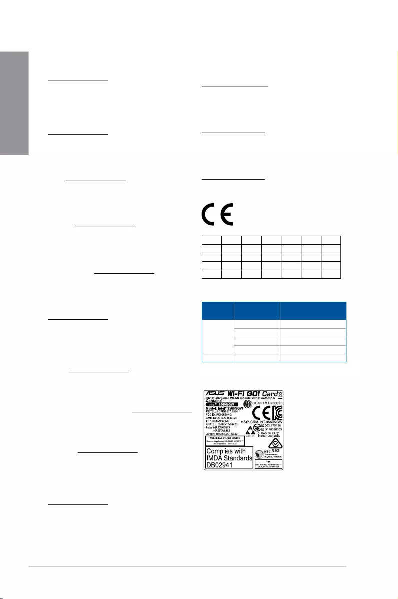
A-6 Appendix
Appendix
Supaprastinta ES atitikties deklaracija
Šiame dokumente bendrovė „ASUSTek Computer Inc.“ pareiškia, kad šis
prietaisas atitinka pagrindinius reikalavimus ir kitas susijusias Direktyvos
2014/53/ES nuostatas. Visas ES atitikties deklaracijos tekstas pateikiamas čia:
https://www.asus.com/support/
Toliau nurodytose šalyse „WiFi“ ryšiu, veikiančiu 5 150–5 350 MHz dažnio
juostoje, galima naudotis tik patalpose:
Ovaj uređaj može da se koristi u državama navedenim ispod:
Forenklet EU-samsvarserklæring
ASUSTek Computer Inc. erklærer herved at denne enheten er i samsvar med
hovedsaklige krav og andre relevante forskrifter i direktivet 2014/53/EU.
Fullstendig tekst for EU-samsvarserklæringen nnes på:
https://www.asus.com/support/
Wi-Fi-området 5150–5350 MHz skal begrenses til innendørs bruk for landene
som er oppført i tabellen:
Uproszczona deklaracja zgodności UE
Firma ASUSTek Computer Inc. niniejszym oświadcza, że urządzenie to jest
zgodne z zasadniczymi wymogami i innymi właściwymi postanowieniami
dyrektywy 2014/53/EU. Pełny tekst deklaracji zgodności UE jest dostępny pod
adresem https://www.asus.com/support/
W krajach wymienionych w tabeli działanie sieci Wi-Fi w paśmie 5150–
5350MHz powinno być ograniczone wyłącznie do pomieszczeń:
Declaração de Conformidade Simplicada da UE
A ASUSTek Computer Inc. declara que este dispositivo está em conformidade
com os requisitos essenciais e outras disposições relevantes da Diretiva
2014/53/UE. O texto integral da declaração de conformidade da UE está
disponível em https://www.asus.com/support/
A utilização das frequências WiFi de 5150 a 5350MHz está restrita a
ambientes interiores nos países apresentados na tabela:
Declarație de conformitate UE, versiune simplicată
Prin prezenta, ASUSTek Computer Inc. declară că acest dispozitiv este în
conformitate cu reglementările esențiale și cu celelalte prevederi relevante
ale Directivei 2014/53/UE. Textul complet al declarației de conformitate UE
este disponibil la adresa https://www.asus.com/support/
Pentru ţările listate în tabelul de mai jos, reţelele WiFi care funcţionează în
banda de frecvenţă de 5.150-5.350 MHz trebuie utilizate doar în interior:
Pojednostavljena Deklaracija o usaglašenosti EU
ASUSTek Computer Inc. ovim izjavljuje da je ovaj uređaj usaglašen sa
osnovnim zahtevima i drugim relevantnim odredbama Direktive 2014/53/EU.
Ceo tekst Deklaracije o usaglašenosti EU dostupan je na lokaciji
https://www.asus.com/support/
WiFi koji radi u frekventnom opsegu od 5150 MHz do 5350 MHz ograničen
je isključivo na upotrebu u zatvorenom prostoru za zemlje navedene u
tabeli ispod:
Zjednodušené vyhlásenie o zhode platné pre EÚ
Spoločnosť ASUSTek Computer Inc. týmto vyhlasuje, že toto zariadenie je
v súlade so základnými požiadavkami a ďalšími príslušnými ustanoveniami
smernice č. 2014/53/EÚ. Plné znenie vyhlásenia o zhode pre EÚ je k dispozícii
na lokalite https://www.asus.com/support/
Činnosť WiFi v pásme 5150 — 5350 MHz bude obmedzená na použitie vo
vnútornom prostredí pre krajiny uvedené v tabuľke nižšie:
Poenostavljena izjava EU o skladnosti
ASUSTek Computer Inc. tukaj izjavlja, da je ta naprava skladna s temeljnimi
zahtevami in drugimi relevantnimii določili Direktive 2014/53/EU. Polno
besedilo izjave EU o skladnosti je na voljo na https://www.asus.com/support/
WiFi, ki deluje v pasovnem območju 5150–5350MHz, mora biti v državah,
navedenih v spodnjem seznamu, omejen na notranjo uporabo:
Declaración de conformidad simplicada para la UE
Por la presente, ASUSTek Computer Inc. declara que este dispositivo cumple
los requisitos básicos y otras disposiciones pertinentes de la directiva
2014/53/EU. En https://www.asus.com/support/ está disponible el texto
completo de la declaración de conformidad para la UE.
La conexión WiFi con una frecuencia de funcionamiento de 5150-5350 MHz
se restringirá al uso en interiores para los países enumerados en la tabla:
Förenklad EU-försäkran om överensstämmelse
ASUSTek Computer Inc. deklarerar härmed att denna enhet överensstämmer
med de grundläggande kraven och andra relevanta bestämmelser i direktiv
2014/53/EU. Fullständig text av EU-försäkran om överensstämmelse nns på
https://www.asus.com/support/
WiFi som använder 5150-5350 MHz kommer att begränsas för användning
inomhus i de länder som anges i tabellen:
ประกาศเกี่ยวกับความสอดคล้องของสหภาพยุโรปแบบย่อ
ASUSTek Computer Inc.
ขอประกาศในที่นี้ว่าอุปกรณ์นี้มีความสอดคล้องกับความ
ต้องการที่จำาเป็นและเงื่อนไขที่เกี่ยวข้องอื่น ๆ ของบทบัญญัติข้อกำาหนด
2014/53/EU เนื้อหาที่สมบูรณ์ของประกาศความสอดคล้องกับ EU มีอยู่ที่
https://www.asus.com/support/
การทำางานของ WiFi ที่ 5150-5350MHz
ถูกจำากัดให้ใช้ในอาคารสำาหรับประเทศที่แสดงในตาราง
Basitleştirilmiş AB Uyumluluk Bildirimi
ASUSTek Computer Inc., bu aygıtın 2014/53/EU Yönergesinin temel
gereksinimlerine ve diğer ilgili hükümlerine uygun olduğunu bildirir. AB
uygunluk bildiriminin tam metni şu adreste bulunabilir:
https://www.asus.com/support/
5150-5350 MHz arasındaki WiFi çalışması, tabloda listelenen ülkeler için iç
mekân kullanımıyla kısıtlanacaktır.
Спрощена декларація про відповідність нормам ЄС
ASUSTek Computer Inc. заявляє, що цей пристрій відповідає основним
вимогам та іншим відповідним вимогам Директиви 2014 / 53 / EU.
Повний текст декларації відповідності нормам ЄС доступний на
https://www.asus.com/support/
Робота Wi-Fi на частоті 5150-5350 МГц обмежується використанням у
приміщенні для країн, поданих у таблиці нижче:
AT BE BG CZ DK EE FR
DE IS IE IT EL ES CY
LV LI LT LU HU MT NL
NO PL PT RO SI SK TR
FI SE CH UK HR
Intel® 9560 NGW output power table:
Function Frequency Maximum Output Power
(EIRP)
WiFi
2400 — 2483.5 MHz 16.63 dBm
5150 — 5350 MHz 17.62 dBm
5470 — 5725 MHz 17.62 dBm
5725 — 5850 MHz 8.41 dBm
Bluetooth 2400 — 2483.5 MHz 8.73 dBm
For the standard EN 300 440 V2.1.1, if this device operates in
5725-5875 MHz, it will be considered as a receiver category 2.

ROG STRIX Z390-E GAMING A-7
Appendix
ASUS contact information
ASUSTeK COMPUTER INC.
Address 4F, No. 150, Li-Te Road, Peitou, Taipei 112, Taiwan
Telephone +886-2-2894-3447
Fax +886-2-2890-7798
Web site www.asus.com
Technical Support
Telephone +86-21-38429911
Fax +86-21-5866-8722, ext. 9101#
Online support http://qr.asus.com/techserv
ASUS COMPUTER INTERNATIONAL (America)
Address 48720 Kato Rd., Fremont, CA 94538, USA
Telephone +1-510-739-3777
Fax +1-510-608-4555
Web site http://www.asus.com/us/
Technical Support
Support fax +1-812-284-0883
Telephone +1-812-282-2787
Online support http://qr.asus.com/techserv
ASUS COMPUTER GmbH (Germany and Austria)
Address Harkort Str. 21-23, 40880 Ratingen, Germany
Fax +49-2102-959931
Web site http://www.asus.com/de
Online contact http://eu-rma.asus.com/sales
Technical Support
Telephone +49-2102-5789555
Support Fax +49-2102-959911
Online support http://qr.asus.com/techserv

A-8 Appendix
Appendix
Manuals.eu
- Manuals.eu
- ASUS
- Computers & Peripherals
- Motherboards
- Intel platform
- ROG STRIX Z390-E GAMING
- Z390 Series Feature Manual
×
1
2
3
4
5
6
7
8
9
10
11
12
13
14
15
16
17
18
19
20
21
22
23
24
25
26
27
28
29
30
31
32
33
34
35
36
37
38
39
40
41
42
43
44
45
46
47
48
49
50
51
52
53
54
55
56
57
58
59
60
61
62
63
64
65
66
67
68
69
70
71
72
⟨
⟩
Copyright © Manuals.eu
Agreement
Privacy Policy
Contact us
Asus
Loading…
S
- STRIX-GTX1050TI-O4G-GAMING
- STRIX-GTX1080TI 11G GAMING
- STRIX-GTX750TI-OC-2GD52
- STRIX-GTX960-DC2OC-2GD52
- STRIX-GTX970-DC2OC-4GD54
- STRIX-GTX980-DC2OC-4GD52
- STRIX-H270F
- STRIX-R9285-DC2OC-2GD52
- Strix Scope TKL Gundam LTD
- Strix Soar2
- STRIX TACTIC PRO34
- Strix TRX40-E Gaming4
- STRIX TRX40-XE GAMING4
- STRIX X299-E GAMING6
- Strix X299-E Gaming II6
- STRIX X299-XE GAMING2
- STRIX X370-F GAMING4
- STRIX X370-I GAMING4
- STRIX X399-E GAMING4
- STRIX X470-F GAMING5
- STRIX X470-I GAMING7
- Strix X570-E Gaming6
- Strix X570-F Gaming6
- Strix X570-I Gaming6
- STRIX X99
- STRIX X99 GAMING7
- STRIX XF 120
- Strix XG17AHP23
- Strix XG17AHPE21
- Strix XG248Q24
- Strix XG258Q26
- Strix XG279Q22
- Strix XG279Q-G22
- Strix XG279Q Gundam edition22
- Strix XG27UQ23
- STRIX XG27VQ23
- Strix XG27WQ22
- Strix XG32VC29
- Strix XG32VQ25
- STRIX XG32VQR25
- Strix XG35VQ25
- Strix XG438Q25
- Strix XG43UQ
- Strix XG43VQ
- Strix XG49VQ25
- STRIX Z270E GAMING10
- STRIX Z270F
- Strix Z270F Gaming10
- Strix Z270F Gaming RG
- Strix Z270G Gaming6
- Strix Z270H Gaming8
- STRIX Z270I
- STRIX Z270-I GAMING9
- STRIX Z370-E GAMING4
- STRIX Z370-F GAMING3
- STRIX Z370-G GAMING3
- STRIX Z370-H GAMING3
- STRIX Z370-I GAMING4
- STRIX Z390-E GAMING4
- STRIX Z390-F GAMING5
- STRIX Z390-H GAMING3
- STRIX Z390-I GAMING7
- STRIX Z490-A GAMING7
- STRIX Z490-E GAMING5
- STRIX Z490-F GAMING4
- STRIX Z490-G GAMING7
- STRIX Z490-H GAMING5
- STRIX Z490-I GAMING5
- STRIX Z590-A GAMING WIFI4
- Strix Z590-E Gaming3
- Strix Z590-F Gaming2
- STRIX Z590-I GAMING WIFI5
- STYLUS
- STYLUS E7303
- SURROUNDVIEW
- SV1
- SV1T5
- SV1TS
- SV4252
- SV425-Y2
- SV427
- SV465
- SV467
- SV5552
- SV557
- sw1
- SW10029
- SW2882
- SW5094
- SW6072
- SW6428
- SW6951
- SW7300
- SW7360
- SW7431
- SW7493
- SW7510
- SW7685
- SW7780
- SW7825
Loading…
Loading…
Nothing found
STRIX Z390-E GAMING
User’s Manual
78 pgs7.12 Mb0
User’s Manual [fr]
100 pgs6.18 Mb0
User’s Manual [zh]
98 pgs6.63 Mb0
User’s Manual [zh]
96 pgs6.74 Mb0
Table of contents
Loading…
…
Asus User’s Manual [fr]
Download
Specifications and Main Features
Frequently Asked Questions
User Manual

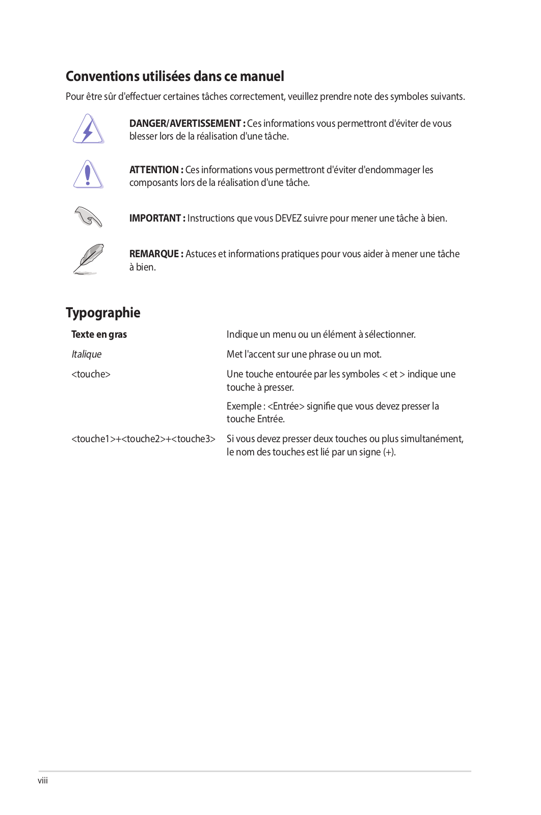
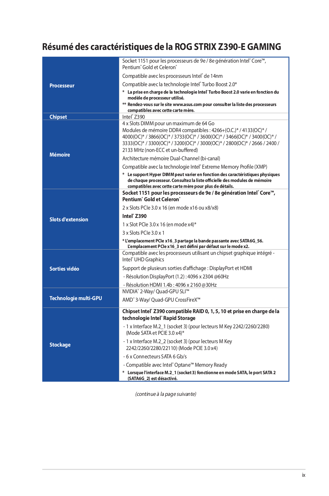
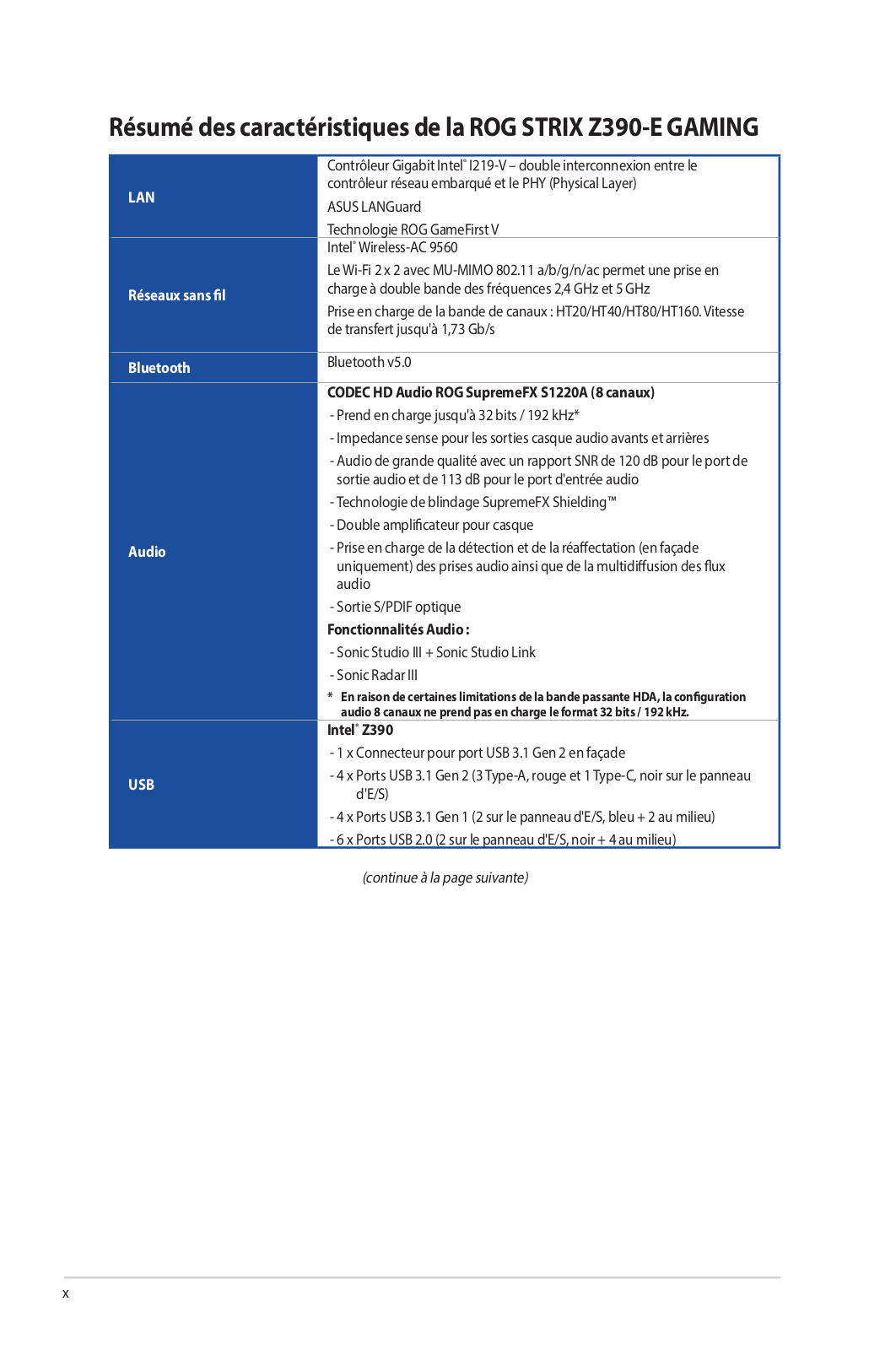
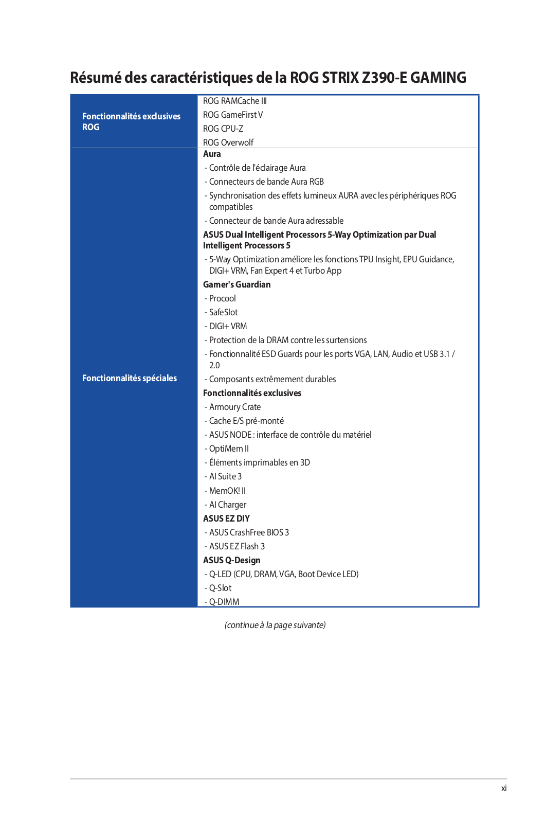
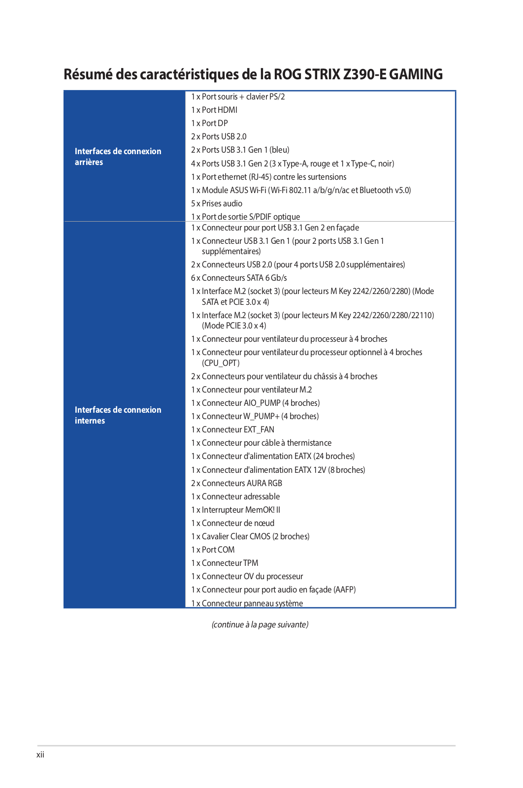
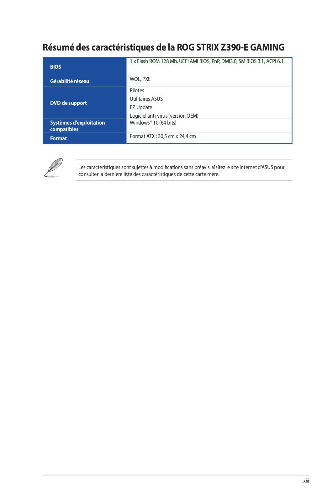
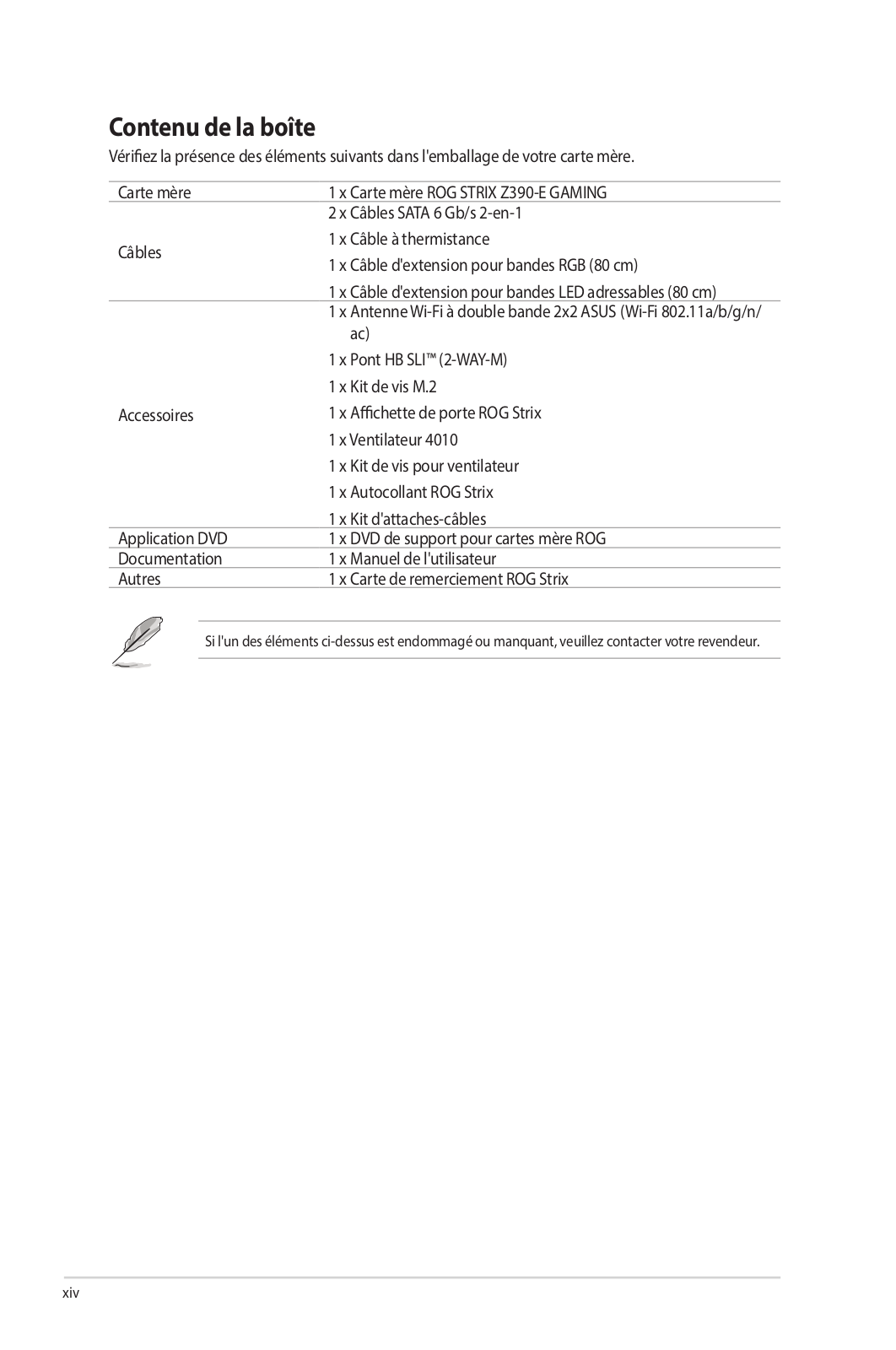
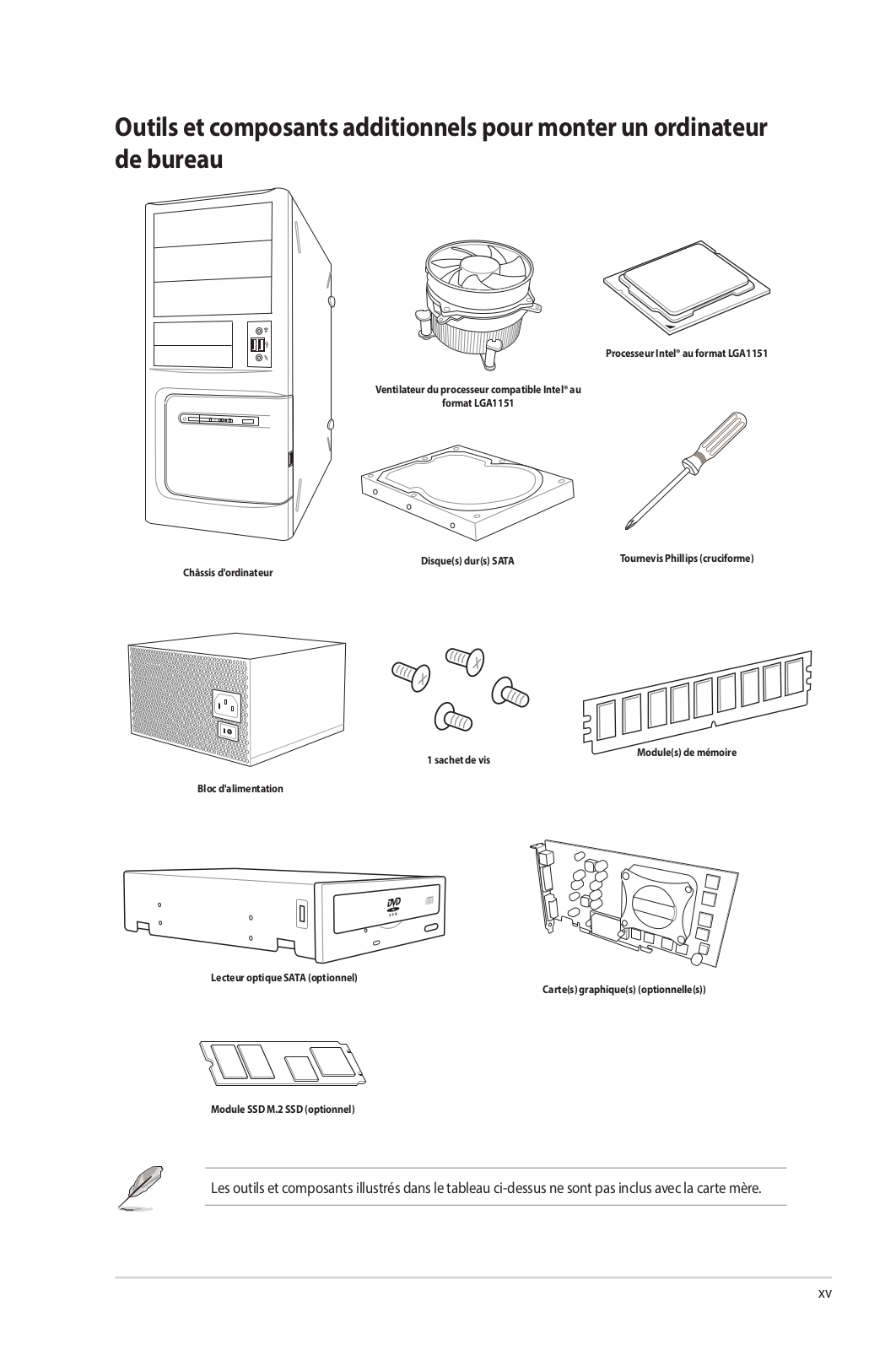

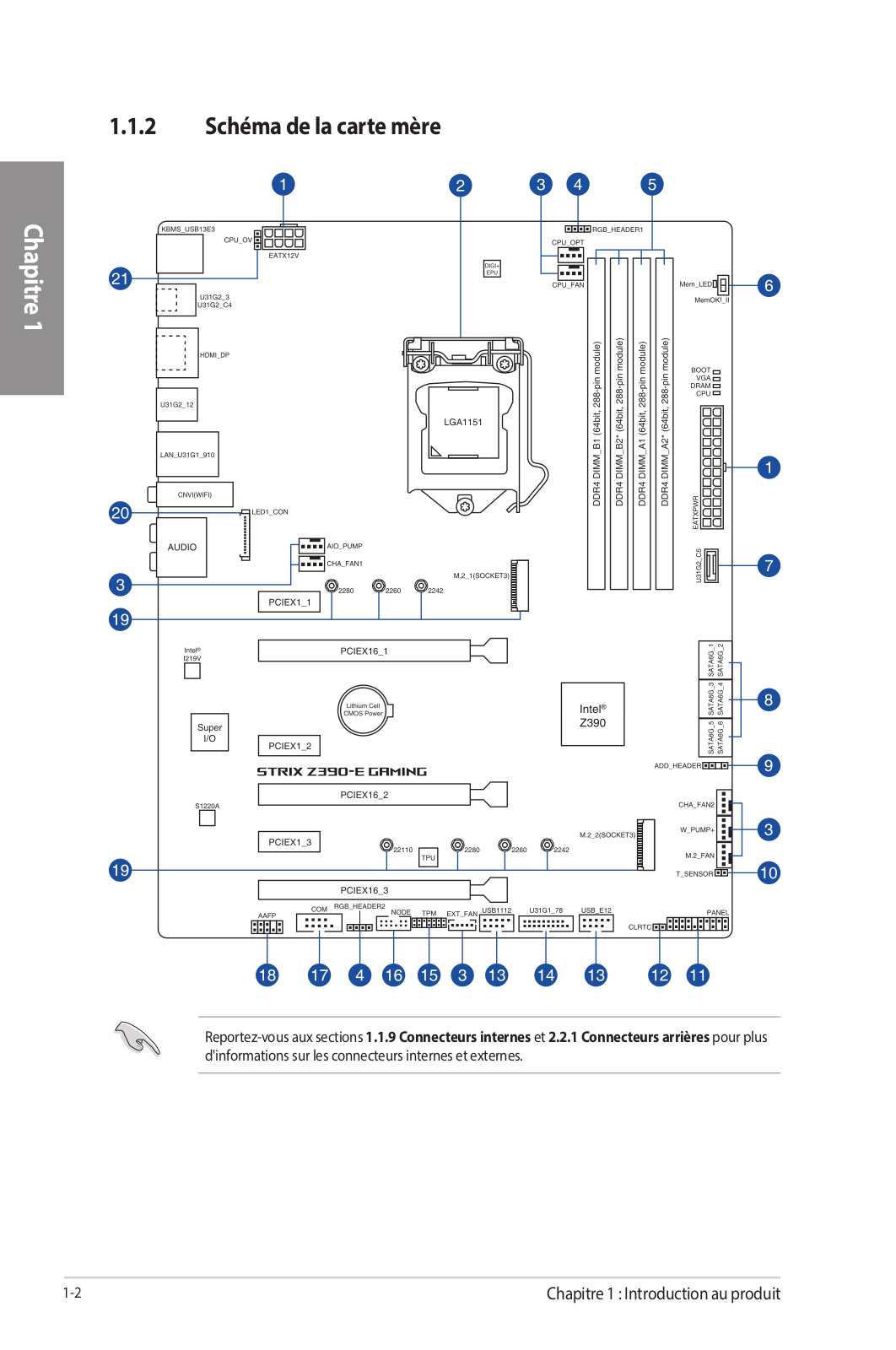
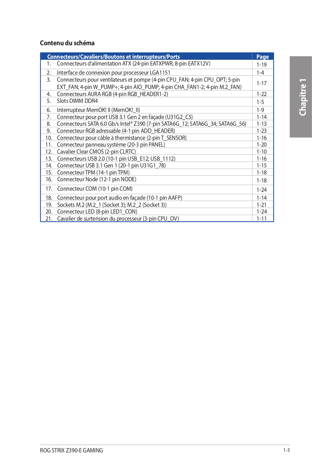
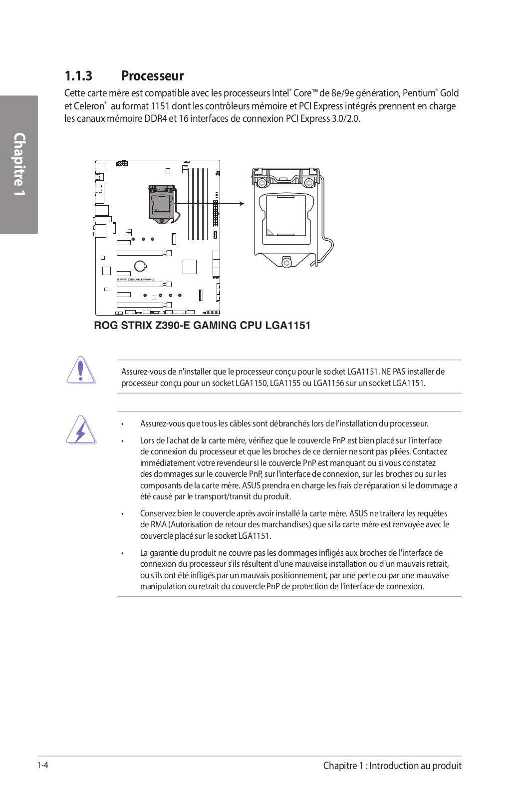
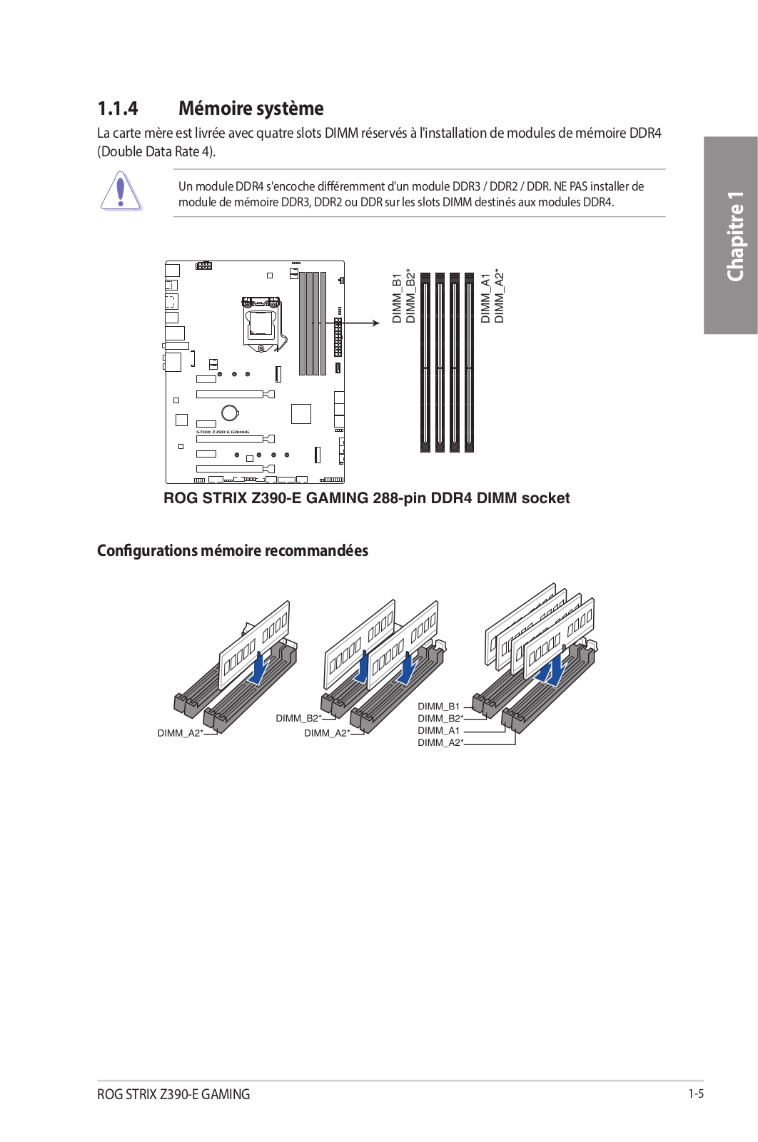
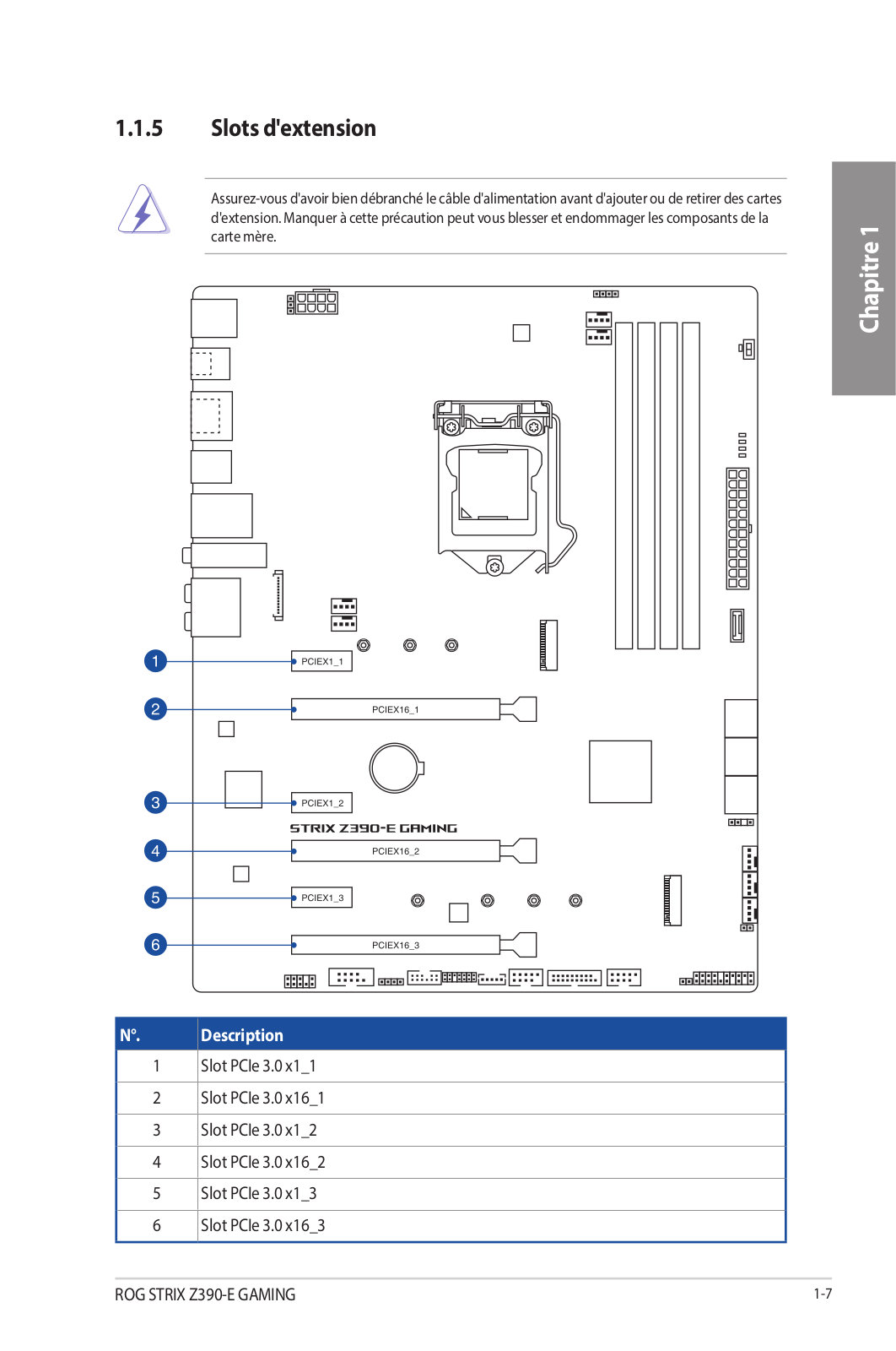
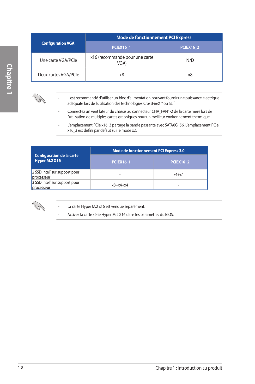
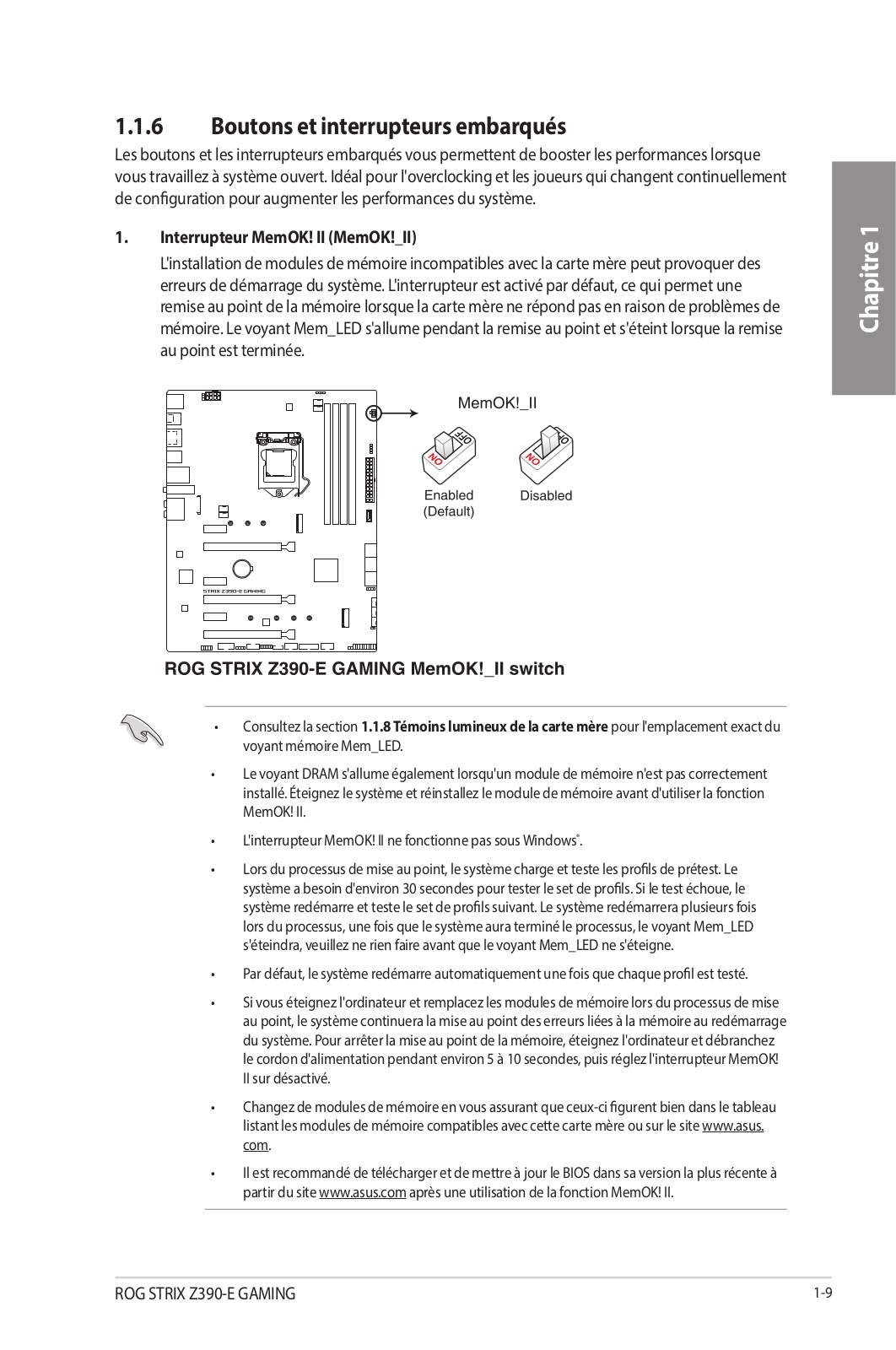
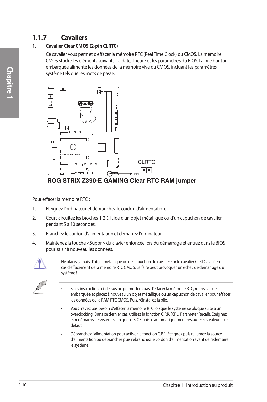
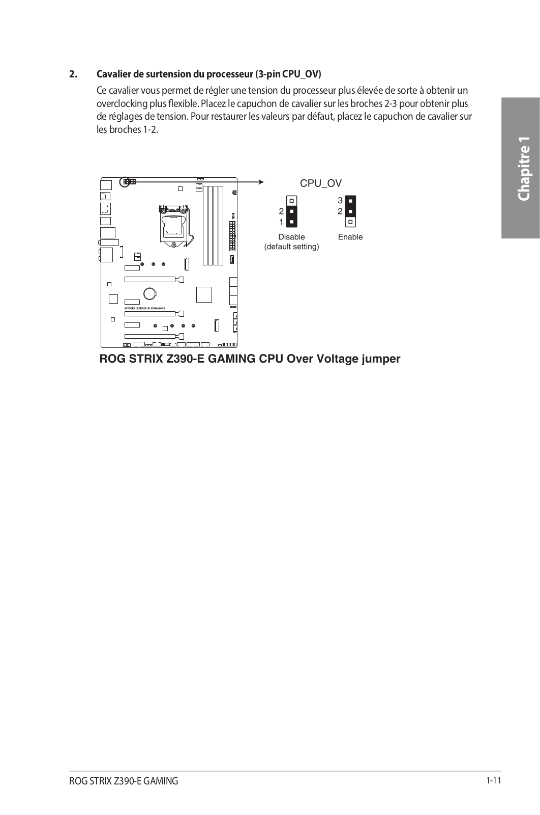
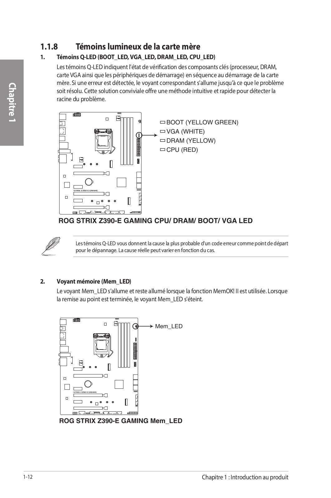
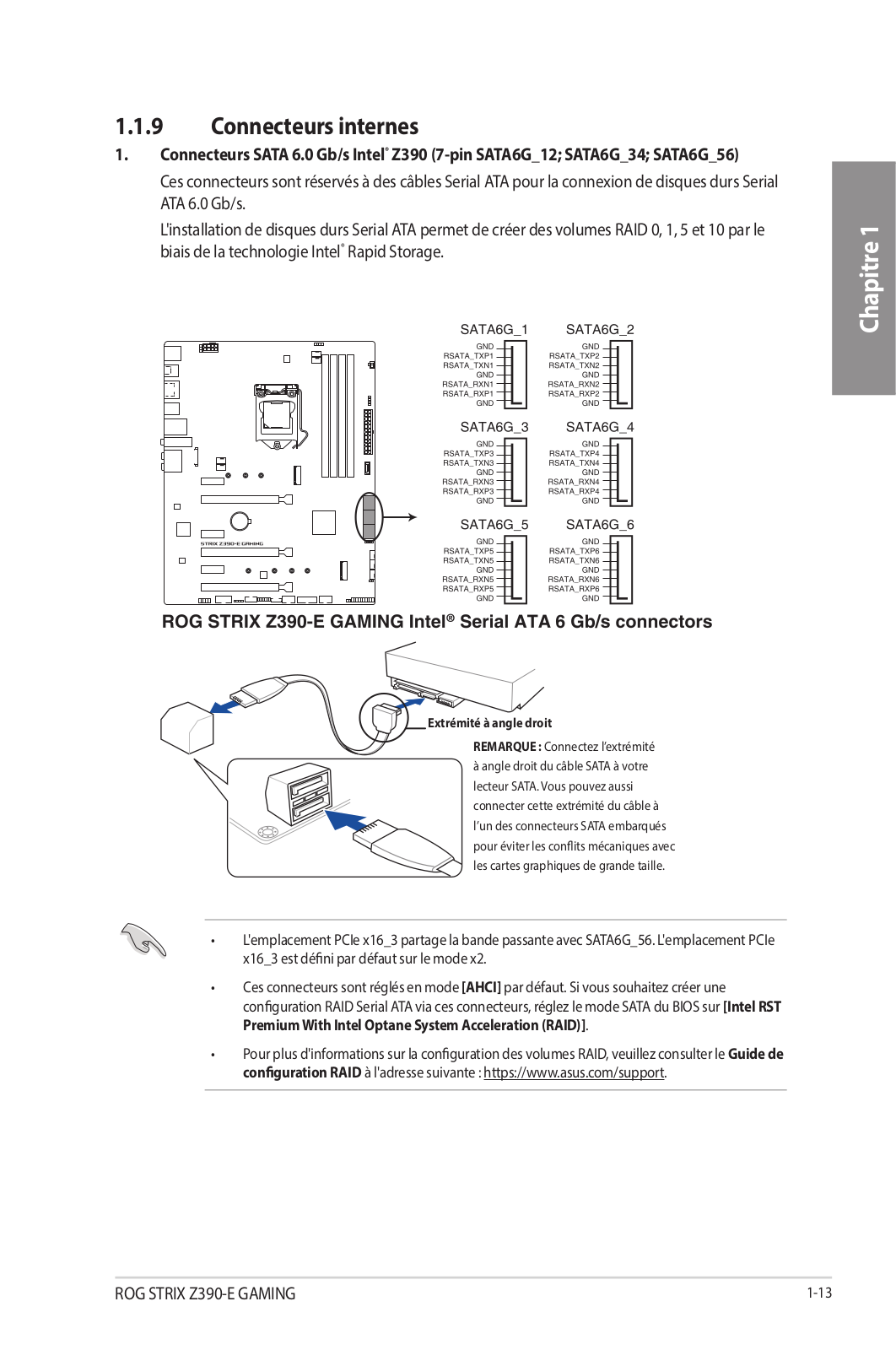
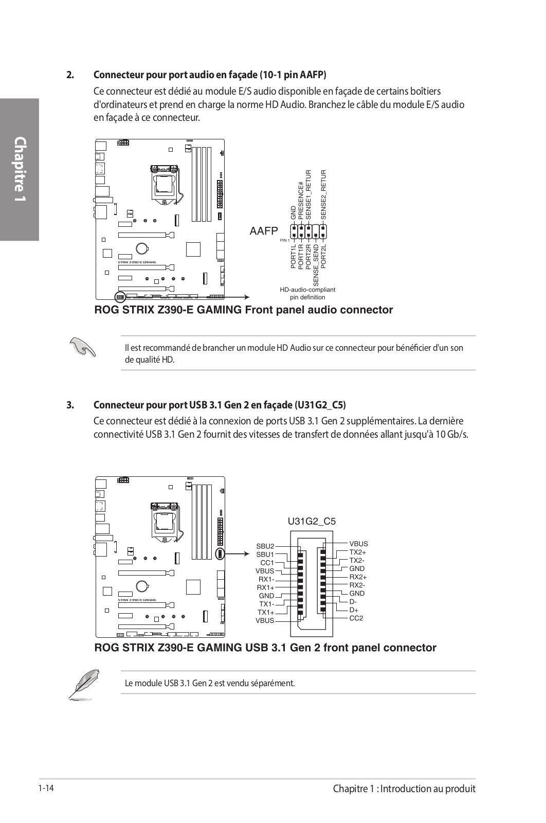
Loading…
+ 70 hidden pages
You need points to download manuals.
1 point = 1 manual.
You can buy points or you can get point for every manual you upload.
Buy points
Upload your manuals
E14841
Revised Edition V2
September 2018
Copyright © 2018 ASUSTeK COMPUTER INC. All Rights Reserved.
No part of this manual, including the products and software described in it, may be reproduced,
transmitted, transcribed, stored in a retrieval system, or translated into any language in any form or by any
means, except documentation kept by the purchaser for backup purposes, without the express written
permission of ASUSTeK COMPUTER INC. («ASUS»).
Product warranty or service will not be extended if: (1) the product is repaired, modified or altered, unless
such repair, modification of alteration is authorized in writing by ASUS; or (2) the serial number of the
product is defaced or missing.
ASUS PROVIDES THIS MANUAL «AS IS» WITHOUT WARRANTY OF ANY KIND, EITHER EXPRESS
OR IMPLIED, INCLUDING BUT NOT LIMITED TO THE IMPLIED WARRANTIES OR CONDITIONS OF
MERCHANTABILITY OR FITNESS FOR A PARTICULAR PURPOSE. IN NO EVENT SHALL ASUS, ITS
DIRECTORS, OFFICERS, EMPLOYEES OR AGENTS BE LIABLE FOR ANY INDIRECT, SPECIAL,
INCIDENTAL, OR CONSEQUENTIAL DAMAGES (INCLUDING DAMAGES FOR LOSS OF PROFITS,
LOSS OF BUSINESS, LOSS OF USE OR DATA, INTERRUPTION OF BUSINESS AND THE LIKE),
EVEN IF ASUS HAS BEEN ADVISED OF THE POSSIBILITY OF SUCH DAMAGES ARISING FROM ANY
DEFECT OR ERROR IN THIS MANUAL OR PRODUCT.
SPECIFICATIONS AND INFORMATION CONTAINED IN THIS MANUAL ARE FURNISHED FOR
INFORMATIONAL USE ONLY, AND ARE SUBJECT TO CHANGE AT ANY TIME WITHOUT NOTICE,
AND SHOULD NOT BE CONSTRUED AS A COMMITMENT BY ASUS. ASUS ASSUMES NO
RESPONSIBILITY OR LIABILITY FOR ANY ERRORS OR INACCURACIES THAT MAY APPEAR IN THIS
MANUAL, INCLUDING THE PRODUCTS AND SOFTWARE DESCRIBED IN IT.
Products and corporate names appearing in this manual may or may not be registered trademarks or
copyrights of their respective companies, and are used only for identification or explanation and to the
owners’ benefit, without intent to infringe.
Offer to Provide Source Code of Certain Software
This product contains copyrighted software that is licensed under the General Public License («GPL»),
under the Lesser General Public License Version («LGPL») and/or other Free Open Source Software
Licenses. Such software in this product is distributed without any warranty to the extent permitted by the
applicable law. Copies of these licenses are included in this product.
Where the applicable license entitles you to the source code of such software and/or other additional data,
you may obtain it for a period of three years after our last shipment of the product, either
(1) for free by downloading it from https://www.asus.com/support/
or
(2) for the cost of reproduction and shipment, which is dependent on the preferred carrier and the location
where you want to have it shipped to, by sending a request to:
ASUSTeK Computer Inc.
Legal Compliance Dept.
15 Li Te Rd.,
Beitou, Taipei 112
Taiwan
In your request please provide the name, model number and version, as stated in the About Box of the
product for which you wish to obtain the corresponding source code and your contact details so that we
can coordinate the terms and cost of shipment with you.
The source code will be distributed WITHOUT ANY WARRANTY and licensed under the same license as
the corresponding binary/object code.
This offer is valid to anyone in receipt of this information.
ASUSTeK is eager to duly provide complete source code as required under various Free Open Source
Software licenses. If however you encounter any problems in obtaining the full corresponding source
code we would be much obliged if you give us a notification to the email address gpl@asus.com, stating
the product and describing the problem (please DO NOT send large attachments such as source code
archives, etc. to this email address).
ii
Инструкция
Посмотреть инструкция для Asus Rog Strix Z390-E Gaming бесплатно. Руководство относится к категории материнские платы, 3 человек(а) дали ему среднюю оценку 7.6. Руководство доступно на следующих языках: английский. У вас есть вопрос о Asus Rog Strix Z390-E Gaming или вам нужна помощь?
Задайте свой вопрос здесь
Ниже вы найдете технические характеристики изделия и руководства по эксплуатации Asus Rog Strix Z390-E Gaming.
Материнская плата Asus Rog Strix Z390-E Gaming поддерживает операционные системы Windows 10 и предназначена для ПК. Используется чипсет Intel Z390. Форм-фактор платы — ATX с шириной 305 мм и глубиной 244 мм. В мотеринской плате интегрирован звук с выходными каналами 7.1. В BIOS используется тип UEFI AMI с объемом памяти 16 Мбит. ACPI версии 6.1. Кабели SATA входят в комплект поставки вместе с инструкцией на русском языке. Также есть два USB-разъема 2.0.
Поддерживаемые типы памяти
DDR4-SDRAM
Поддерживаемые операционные системы Windows
Windows 10
Главная
| Бренд | Asus |
| Модель | Rog Strix Z390-E Gaming | 90MB0YF0-M0EAY1 |
| Изделие | материнская плата |
| EAN | 0192876122839, 4718017122832 |
| Язык | английский |
| Тип файла | Руководство пользователя (PDF) |
Память
| Поддерживаемые типы памяти | DDR4-SDRAM |
| Тип слотов памяти | DIMM |
| Количество слотов памяти | 4 |
| Небуферизованная память | Да |
| Максимальная внутренняя память | 64 GB |
| Поддерживаемые частоты памяти | 2133,2400,2666,2800,3000,3200,3300,3333,3400,3466,3600,3733,3866,4000,4133,4266 MHz |
| Каналы памяти | Dual-channel |
Свойства
| Поддерживаемые операционные системы Windows | Windows 10 |
| Комплектующие для | ПК |
| Семейство чипсета материнской платы | Intel |
| Чипсет материнской платы | Intel Z390 |
| Формат материнской платы | ATX |
| Выходные звуковые каналы | 7.1 канала |
Вес и размеры
| Ширина | 305 mm |
| Глубина | 244 mm |
BIOS
| Тип BIOS | UEFI AMI |
| Размер памяти BIOS | 16 Mbit |
| Версия ACPI | 6.1 |
| Перемычка Clear CMOS | Да |
Содержимое упаковки
| Поставляемые кабели | SATA |
| Инструкция | Да |
Внутренние порты
| Разъемы USB 2.0 | 2 |
| Разъемы USB 3.2 Gen 1 (3.1 Gen 1) | 1 |
| Разъемы USB 3.2 Gen 2 (3.1 Gen 2) | 1 |
| Количество разъемов SATA III | 6 |
| Количество разъемов SATA II | 0 |
| Количество параллельных разъемов ATA (PATA) | 0 |
| Разъем вентилятора центрального процессора | Да |
| Количество разъемов вентилятора корпуса | 2 |
| Разъем питания ATX (24-конт.) | Да |
| Количество разъемов питания EATX | 1 |
Слоты расширения
| Количество M.2 (M) слотов | 2 |
| Слоты PCI Express x1 (поколение 3.x) | 3 |
| Слоты PCI Express x16 (поколение 3.x) | 3 |
Порты на задней панели
| Количество портов USB 2.0 | 2 |
| Количество портов USB 3.2 Gen 1 (3.1 Gen 1) Type-A | 2 |
| Количество портов USB 3.2 Gen 1 (3.1 Gen 1) Type-С | 0 |
| Количество портов USB 3.2 Gen 2 (3.1 Gen 2) Type-A | 3 |
| Количество портов USB 3.2 Gen 2 (3.1 Gen 2) Type-С | 1 |
| Количество портов Ethernet LAN ( RJ-45) | 1 |
| Количество портов eSATA | 0 |
| Количество портов PS/2 | 0 |
| Порты FireWire | 0 |
| Количество портов VGA (D-Sub) | 0 |
| Количество HDMI портов | 1 |
| Количество портов DVI-D | 0 |
| Количество портов DisplayPort | 1 |
| Порт выхода S/PDIF | Да |
| Линейные выходы наушников | 1 |
| Линейный вход микрофона | Да |
Сеть
| Bluetooth | Да |
| Версия Bluetooth | 5.0 |
| Wi-Fi | Да |
| Wi-Fi стандартов | 802.11a, Wi-Fi 5 (802.11ac), 802.11b, 802.11g, Wi-Fi 4 (802.11n) |
| Подключение Ethernet | Да |
| Контроллер LAN | Intel® I219-V |
Контроллеры хранения данных
Особые свойства процессора
| Intel® Optane™ Memory Ready | Да |
| Intel® InTru™ 3D Technology | Да |
| Intel® Insider™ | Да |
| Intel® Quick Sync Video Technology | Да |
| Intel Clear Video HD Technology | Да |
| экстремальный профиль памяти Intel | Да |
| Технология Intel Turbo Boost | 2.0 |
Графический адаптер
| Поддержка технологии параллельной обработки | 2-Way SLI, 3-Way CrossFireX |
| Максимальное разрешение | 4096 x 2160 пикселей |
| Видеокарта | HD Graphics |
| Семейство графического адаптера | Intel |
Процессор
| Производитель процессора | Intel |
| Совместимые серии процессоров | Intel Celeron, Intel Pentium |
| Сокет процессора | LGA 1151 (разъем H4) |
показать больше
Часто задаваемые вопросы
Не можете найти ответ на свой вопрос в руководстве? Вы можете найти ответ на свой вопрос ниже, в разделе часто задаваемых вопросов о Asus Rog Strix Z390-E Gaming.
Какая ширина Asus Rog Strix Z390-E Gaming?
Asus Rog Strix Z390-E Gaming имеет ширину 305 mm.
Какая толщина Asus Rog Strix Z390-E Gaming?
Asus Rog Strix Z390-E Gaming имеет толщину 244 mm.
Инструкция Asus Rog Strix Z390-E Gaming доступно в русский?
К сожалению, у нас нет руководства для Asus Rog Strix Z390-E Gaming, доступного в русский. Это руководство доступно в английский.
Не нашли свой вопрос? Задайте свой вопрос здесь