

Motherboard
TUF GAMING
Z590-PLUS WIFI

ii
E17660
First Edition
January 2021
Copyright © 2021 ASUSTeK COMPUTER INC. All Rights Reserved.
No part of this manual, including the products and software described in it, may be reproduced,
transmitted, transcribed, stored in a retrieval system, or translated into any language in any form or by
any means, except documentation kept by the purchaser for backup purposes, without the express
written permission of ASUSTeK COMPUTER INC. (“ASUS”).
Product warranty or service will not be extended if: (1) the product is repaired, modified or altered, unless
such repair, modification of alteration is authorized in writing by ASUS; or (2) the serial number of the
product is defaced or missing.
ASUS PROVIDES THIS MANUAL “AS IS” WITHOUT WARRANTY OF ANY KIND, EITHER EXPRESS
OR IMPLIED, INCLUDING BUT NOT LIMITED TO THE IMPLIED WARRANTIES OR CONDITIONS OF
MERCHANTABILITY OR FITNESS FOR A PARTICULAR PURPOSE. IN NO EVENT SHALL ASUS, ITS
DIRECTORS, OFFICERS, EMPLOYEES OR AGENTS BE LIABLE FOR ANY INDIRECT, SPECIAL,
INCIDENTAL, OR CONSEQUENTIAL DAMAGES (INCLUDING DAMAGES FOR LOSS OF PROFITS,
LOSS OF BUSINESS, LOSS OF USE OR DATA, INTERRUPTION OF BUSINESS AND THE LIKE),
EVEN IF ASUS HAS BEEN ADVISED OF THE POSSIBILITY OF SUCH DAMAGES ARISING FROM
ANY DEFECT OR ERROR IN THIS MANUAL OR PRODUCT.
SPECIFICATIONS AND INFORMATION CONTAINED IN THIS MANUAL ARE FURNISHED FOR
INFORMATIONAL USE ONLY, AND ARE SUBJECT TO CHANGE AT ANY TIME WITHOUT NOTICE,
AND SHOULD NOT BE CONSTRUED AS A COMMITMENT BY ASUS. ASUS ASSUMES NO
RESPONSIBILITY OR LIABILITY FOR ANY ERRORS OR INACCURACIES THAT MAY APPEAR IN
THIS MANUAL, INCLUDING THE PRODUCTS AND SOFTWARE DESCRIBED IN IT.
Products and corporate names appearing in this manual may or may not be registered trademarks or
copyrights of their respective companies, and are used only for identification or explanation and to the
owners’ benefit, without intent to infringe.

iii
Contents
Safety information ………………………………………………………………………………………… iv
About this guide ……………………………………………………………………………………………. v
TUF GAMING Z590-PLUS WIFI specifications summary …………………………………. vi
Connectors with shared bandwidth ……………………………………………………………….. x
Package contents …………………………………………………………………………………………. xi
Installation tools and components ……………………………………………………………….. xii
Chapter 1: Product Introduction
1.1 Before you proceed ………………………………………………………………………..1-1
1.2 Motherboard layout …………………………………………………………………………1-2
Chapter 2: Basic Installation
2.1 Building your PC system …………………………………………………………………2-1
2.1.1 CPU installation…………………………………………………………………2-1
2.1.2 Cooling system installation………………………………………………….2-3
2.1.3 DIMM installation……………………………………………………………….2-5
2.1.4 M.2 installation ………………………………………………………………….2-6
2.1.5 Motherboard installation ……………………………………………………2-11
2.1.6 ATX power connection …………………………………………………….. 2-12
2.1.7 SATA device connection ………………………………………………….. 2-13
2.1.8 Front I/O connectors ………………………………………………………..2-14
2.1.9 Expansion card installation ……………………………………………….2-15
2.1.10 Wi-Fi antenna installation ………………………………………………….2-17
2.2 Motherboard rear and audio connections ………………………………………2-18
2.2.1 Rear I/O connection ………………………………………………………… 2-18
2.2.2 Audio I/O connections ……………………………………………………… 2-19
2.3 Starting up for the first time …………………………………………………………..2-22
2.4 Turning off the computer ………………………………………………………………2-22
Chapter 3: BIOS and RAID Support
3.1 Knowing BIOS ………………………………………………………………………………..3-1
3.2 BIOS Setup program ……………………………………………………………………….3-2
3.3 EZ Update ………………………………………………………………………………………3-2
3.4 ASUS EZ Flash 3 …………………………………………………………………………….3-3
3.5 ASUS CrashFree BIOS 3 ………………………………………………………………….3-4
3.6 RAID configurations ……………………………………………………………………….3-5
Appendix
Notices …………………………………………………………………………………………………….. A-1
Warranty ……………………………………………………………………………………………………. A-8
ASUS contact information ………………………………………………………………………… A-10

iv
Safety information
Electrical safety
• To prevent electrical shock hazard, disconnect the power cable from the electrical
outlet before relocating the system.
• When adding or removing devices to or from the system, ensure that the power cables
for the devices are unplugged before the signal cables are connected. If possible,
disconnect all power cables from the existing system before you add a device.
• Before connecting or removing signal cables from the motherboard, ensure that all
power cables are unplugged.
• Seek professional assistance before using an adapter or extension cord. These
devices could interrupt the grounding circuit.
• Ensure that your power supply is set to the correct voltage in your area. If you are not
sure about the voltage of the electrical outlet you are using, contact your local power
company.
• If the power supply is broken, do not try to fix it by yourself. Contact a qualified service
technician or your retailer.
Operation safety
• Before installing the motherboard and adding devices on it, carefully read all the
manuals that came with the package.
• Before using the product, ensure all cables are correctly connected and the power
cables are not damaged. If you detect any damage, contact your dealer immediately.
• To avoid short circuits, keep paper clips, screws, and staples away from connectors,
slots, sockets and circuitry.
• Avoid dust, humidity, and temperature extremes. Do not place the product in any area
where it may become wet.
• Place the product on a stable surface.
• If you encounter technical problems with the product, contact a qualified service
technician or your retailer.
• Your motherboard should only be used in environments with ambient temperatures
between 0°C and 40°C.

v
About this guide
This user guide contains the information you need when installing and configuring the
motherboard.
How this guide is organized
This guide contains the following parts:
• Chapter 1: Product Introduction
This chapter describes the features of the motherboard and the new technology it
supports. It includes description of the switches, jumpers, and connectors on the
motherboard.
• Chapter 2: Basic Installation
This chapter lists the hardware setup procedures that you have to perform when
installing system components.
• Chapter 3: BIOS and RAID Support
This chapter tells how to boot into the BIOS, upgrade BIOS using the EZ Flash Utility
and support on RAID.
Where to find more information
Refer to the following sources for additional information and for product and software
updates.
1. ASUS website
The ASUS website (www.asus.com) provides updated information on ASUS hardware
and software products.
2. Optional documentation
Your product package may include optional documentation, such as warranty flyers,
that may have been added by your dealer. These documents are not part of the
standard package.
Conventions used in this guide
To ensure that you perform certain tasks properly, take note of the following symbols used
throughout this manual.
CAUTION: Information to prevent damage to the components and injuries to
yourself when trying to complete a task.
IMPORTANT: Instructions that you MUST follow to complete a task.
NOTE: Tips and additional information to help you complete a task.

vi
TUF GAMING Z590-PLUS WIFI specifications summary
CPU
Intel® Socket LGA1200 for 11th Gen Intel® Core™ processors & 10th Gen
Intel® Core™, Pentium® Gold and Celeron® Processors
Supports Intel® 14 nm CPU
Supports Intel® Turbo Boost Technology 2.0 and Intel® Turbo Boost Max
Technology 3.0**
* Refer to www.asus.com for CPU support list.
** Intel® Turbo Boost Max Technology 3.0 support depends on the CPU types.
Chipset Intel® Z590 Chipset
Memory
4 x DIMM, Max. 128GB, DDR4 5133(OC)5000(OC)/4800(OC)/4700(OC)/
4600(OC)/4500(OC)/4400(OC) /4266(OC)/4133(OC)/4000(OC)/
3866(OC)/3733(OC)/3600(OC)/3466(OC)/3400(OC)/3333(OC)/3200/
3000/2933/2800/2666/2400/2133 MHz Non-ECC, Un-buffered Memory*
Dual Channel Memory Architecture
Supports Intel® Extreme Memory Profile (XMP)
OptiMem II
* 10th Gen Intel® CoreTM i7/ i9 processors support 2933/2800/2666/2400/2133
natively, others will run at the maximum transfer rate of DDR4 2666MHz.
* 11th Gen Intel® processors support 3200/2933/2800/2666/2400/2133 natively.
* Refer to www.asus.com for the Memory QVL (Qualified Vendors Lists), and
memory frequency support depends on the CPU types.
Graphics
1 x DisplayPort 1.4**
1 x HDMITM 2.0***
* Graphics specifications may vary between CPU types.
** Intel® 11th & 10th Gen processors support DisplayPort 1.4 with max. resolution
of 4096 x 2304 @60Hz. Please refer to www.intel.com for any updates.
*** Only Intel® 11th Gen processors, support HDMI™ 2.0 with max. resolution
of 4K@60Hz, others would only support HDMI™ 1.4 with max. resolution of
4K@30Hz. Please refer to www.intel.com for any update.
**** VGA resolution support depends on processors’ or graphic cards’ resolution.
Expansion Slots
Intel® 11th & 10th Gen Processors
1 x PCIe 4.0/3.0 x16 slot*
— Intel® 11th Gen processors support PCIe 4.0 x16
— Intel® 10th Gen processors support PCIe 3.0 x16
Intel® Z590 Chipset
1 x PCIe 3.0 x16 slot (supports x4 mode)
2 x PCIe 3.0 x1 slots
* Enable RST PCIe Storage Remapping for PCH attached PCIe slots to activate
Intel® Optane Memory.
Storage
Total supports 3 x M.2 slots and 6 x SATA 6Gb/s ports
Intel® 11th Gen Processors
M.2_1 slot (Key M), type 2242/2260/2280/22110
— Only Intel® 11th Gen processors support PCIe 4.0 x4 mode, this slot
will be disabled for other CPUs
Intel® Z590 Chipset
M.2_2 slot (Key M), type 2242/2260/2280/22110
(supports PCIe 3.0 x4 & SATA modes)***
M.2_3 slot (Key M), type 2242/2260/2280
(supports PCIe 3.0 x4 & SATA modes)****
6 x SATA 6Gb/s ports
(continued on the next page)

vii
TUF GAMING Z590-PLUS WIFI specifications summary
Storage
* Raid function for PCIe mode SSD in Intel® Rapid Storage Technology is
available with either
1. Intel® SSDs installed in both CPU-attached and PCH-attached slots, or
2. any other 3rd party SSDs installed in PCH-attached slots.
** To enable Intel® Optane™ Memory (Hybrid Storage device), it must be
installed in PCH-attached slots with Intel® Rapid Storage Technology.
*** M.2_2 shares bandwidth with SATA6G_2. When M.2_2 runs SATA mode,
SATA6G_2 will be disabled.
**** M.2_3 shares bandwidth with SATA6G_56. When M.2_3 is occupied,
SATA6G_56 will be disabled.
Ethernet 1 x Intel® I225-V 2.5Gb Ethernet
TUF LANGuard
Wireless & Bluetooth
Intel® Wi-Fi 6
2×2 Wi-Fi 6 (802.11 a/b/g/n/ac/ax)
Supports 2.4/5GHz frequency band
Bluetooth v5.0 or later
USB
Rear USB (Total 7 ports)
1 x USB 3.2 Gen 2×2 port (1 x USB Type-C®)
2 x USB 3.2 Gen 2 ports (2 x Type-A)
2 x USB 3.2 Gen 1 ports (2 x Type-A)
2 x USB 2.0 ports (2 x Type-A)
Front USB (Total 7 ports)
1 x USB 3.2 Gen 1 connector (suppports USB Type-C®)
1 x USB 3.2 Gen 1 header supports additional 2 USB 3.2 Gen 1 ports
2 x USB 2.0 headers support additional 4 USB 2.0 ports
Audio
Realtek ALC S1200A 7.1 Surround Sound High Definition Audio
CODEC
— Supports: Jack-detection, Multi-streaming, Front Panel Jack-retasking
— Supports up to 24-Bit/192 kHz playback
Audio Features
— Audio Shielding
— Rear optical S/PDIF out port
— Premium Japanese audio capacitors
— Dedicated audio PCB layers
— Audio cover
Back Panel I/O Ports
1 x USB 3.2 Gen 2×2 port (1 x USB Type-C®)
2 x USB 3.2 Gen 2 ports (2 x Type-A)
2 x USB 3.2 Gen 1 ports (2 x Type-A)
2 x USB 2.0 ports (2 x Type-A)
1 x DisplayPort
1 x HDMITM port
1 x ASUS Wi-Fi Module
1 x Intel® I225-V 2.5Gb Ethernet port
5 x Audio jacks
1 x Optical S/PDIF out port
1 x PS/2 Keyboard/Mouse combo port
(continued on the next page)

viii
TUF GAMING Z590-PLUS WIFI specifications summary
Internal I/O Connectors
Fan and cooling-related
1 x 4-pin CPU Fan header
1 x 4-pin CPU OPT Fan header
1 x 4-pin AIO Pump header
3 x 4-pin Chassis Fan headers
Power related
1 x 24-pin Main Power connector
1 x 8-pin +12V Power connector
1 x 4-pin +12V Power connector
Storage related
3 x M.2 slots (Key M)
6 x SATA 6Gb/s ports
USB
1 x USB 3.2 Gen 1 connector (supports USB Type-C®)
1 x USB 3.2 Gen 1 header supports additional 2 USB 3.2 Gen 1 ports
2 x USB 2.0 headers support additional 4 USB 2.0 ports
Miscellaneous
2 x AURA Addressable Gen 2 headers
2 x AURA RGB headers
1 x Clear CMOS header
1 x COM Port header
1 x Front Panel Audio header (AAFP)
1 x 20-3 pin System Panel header with Chassis intrude function
1 x ThunderboltTM header
Special Features
ASUS TUF PROTECTION
— DIGI+ VRM (- Digital power design with DrMOS)
— Enhanced DRAM Overcurrent Protection
— TUF LANGuard
— Overvoltage Protection
ASUS Q-Design
— M.2 Q-Latch
— Q-DIMM
— Q-LED (CPU [red], DRAM [yellow], VGA [white], Boot Device [yellow
green])
— Q-Slot
ASUS Thermal Solution
— M.2 heatsink
— VRM heatsink design
ASUS EZ DIY
— ProCool
— Pre-mounted I/O shield
— SafeSlot
AURA Sync
— AURA RGB headers
— Addressable Gen 2 RGB headers
(continued on the next page)
ix
TUF GAMING Z590-PLUS WIFI specifications summary
Software Features
ASUS Exclusive Software Features
Armoury Crate
— AURA Creator
— AURA Sync
— Two-Way AI Noise Cancelation
AI Suite 3
— Performance And Power Saving Utility
TurboV Evo
EPU
DIGI + VRM
Fan Xpert 4
— EZ update
TUF GAMING CPU-Z
AI Charger
ASUS Turbo LAN
DAEMON Tools
DTS Custom for GAMING Headsets
MyASUS
Norton Anti-virus software (Free Trial version)
WinRAR
UEFI BIOS
ASUS EZ DIY
— ASUS CrashFree BIOS 3
— ASUS EZ Flash 3
— ASUS UEFI BIOS EZ Mode
BIOS 192 (128+64) Mb Flash ROM, UEFI AMI BIOS
Manageability WOL by PME, PXE
Operating System Windows® 10 64-bit
Form Factor ATX Form Factor
12 inch x 9.6 inch (30.5 cm x 24.4 cm)
• Specifications are subject to change without notice. Please
refer to the ASUS website for the latest specifications.
• MyASUS offers a variety of support features such as helping
to troubleshoot issues, optimizing product performance,
integrating ASUS software, and recovery drive creation.
Please scan the QR Code for installation guide and FAQ.
x
Connectors with shared bandwidth
DDR4 DIMM_A1 (64bit, 288-pin module)
DDR4 DIMM_A2* (64bit, 288-pin module)
DDR4 DIMM_B1 (64bit, 288-pin module)
DDR4 DIMM_B2* (64bit, 288-pin module)
DIGI+
VRM
ASM
1442K
AIO_PUMP
CHA_FAN2
CHA_FAN3
CHA_FAN1
CPU_FAN CPU_OPT
CLRTC
M.2_1(SOCKET3)
M.2_2(SOCKET3)
M.2_3(SOCKET3)
RGB_HEADER1
PANEL
AAFP
SATA6G_1 SATA6G_2
SATA6G_3
128Mb
BIOS
64Mb
BIOS
SATA6G_4
SATA6G_5
RGB_HEADER2
ADD_GEN 2_2
SATA6G_6
ATX_12V_1ATX_12V_2
LGA1200
ATX_PWR
U32G1_910
Intel®
Z590
Intel®
I225-V
BATTERY
LAN_U32G2_34
CNVI(WIFI)
KBMS
_USB1112
HDMI
_DP
AUDIO
Super
I/O
PCIEX1_1
228022602242
2280
2280
22110
22110
2260 2242
22602242
PCIEX1_2
PCIEX16_2
PCIEX16_1
USB_E34USB_E12
M.2_2(SOCKET3)
PCIE SATA IRST
3.0 X4 PCH-attachedV
M.2_1(SOCKET3)
PCIE SATA IRST
4.0 X4 CPU-attachedX
COM TB_HEADER
U32G2X2_1
U32G1_78
U32_5
BOOT
VGA
DRAM
CPU
ADD_GEN 2_1
B
B
A
A
M.2_3(SOCKET3)
PCIE SATA IRST
3.0 X4 PCH-attached
V
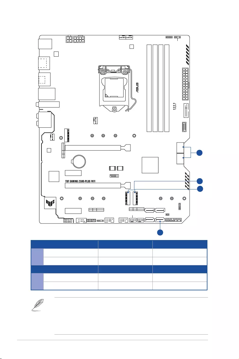
Configuration 1 [Default] 2
AM.2_2 PCIe x4 mode SATA
SATA6G_2 V —
Configuration 1 [Default] 2
BM.2_3 V —
SATA6G_56 — V
• M.2_2 shares bandwidth with SATA6G_2. When M.2_2 runs SATA mode,
SATA6G_2 will be disabled.
• M.2_3 shares bandwidth with SATA6G_56. When M.2_3 is occupied, SATA6G_56
will be disabled.
• Please adjust BIOS setting for changing onboard device configuration.
xi
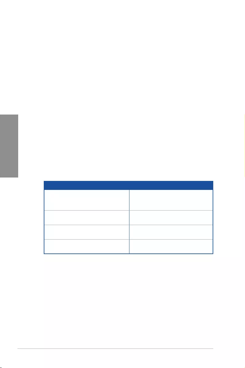
Package contents
Check your motherboard package for the following items.
Motherboard 1 x TUF GAMING Z590-PLUS WIFI motherboard
Cables 2 x SATA 6Gb/s cables
Miscellaneous
1 x ASUS Wi-Fi moving antennas
2 x M.2 Rubber Packages
1 x M.2 SSD screw package
1 x TUF Gaming sticker
Installation Media 1 x Support DVD
Documentation 1 x TUF Certification card
1 x User manual
If any of the above items is damaged or missing, contact your retailer.
xii
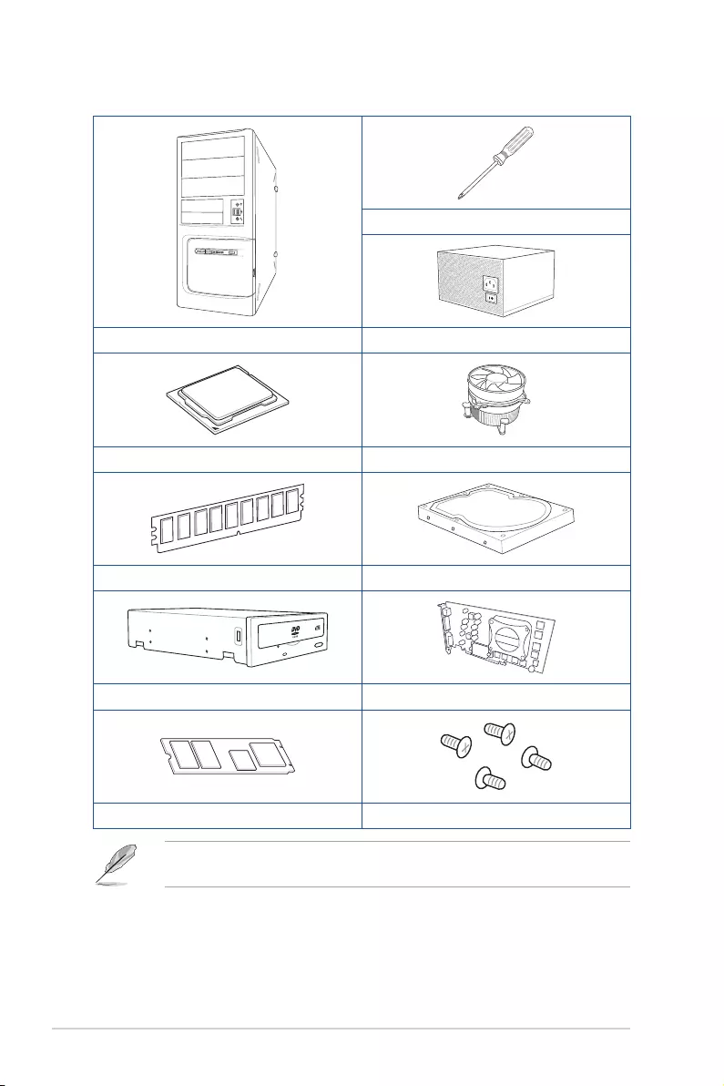
Installation tools and components
Phillips (cross) screwdriver
PC chassis Power supply unit
Intel® LGA 1200 CPU Intel® LGA 1200 compatible CPU Fan
DDR4 DIMM SATA hard disk drive
SATA optical disc drive (optional) Graphics card (optional)
M.2 SSD module (optional) 1 Bag of screws
The tools and components in the table above are not included in the motherboard
package.

TUF GAMING Z590-PLUS WIFI 1-1
Chapter 1
Product Introduction
1
Chapter 1: Product Introduction
• Unplug the power cord from the wall socket before touching any component.
• Before handling components, use a grounded wrist strap or touch a safely grounded
object or a metal object, such as the power supply case, to avoid damaging them due
to static electricity.
• Hold components by the edges to avoid touching the ICs on them.
• Whenever you uninstall any component, place it on a grounded antistatic pad or in
the bag that came with the component.
• Before you install or remove any component, ensure that the ATX power supply is
switched off or the power cord is detached from the power supply. Failure to do so
may cause severe damage to the motherboard, peripherals, or components.
1.1 Before you proceed
Take note of the following precautions before you install motherboard components or
change any motherboard settings.
1-2 Chapter 1: Product Introduction
Chapter 1
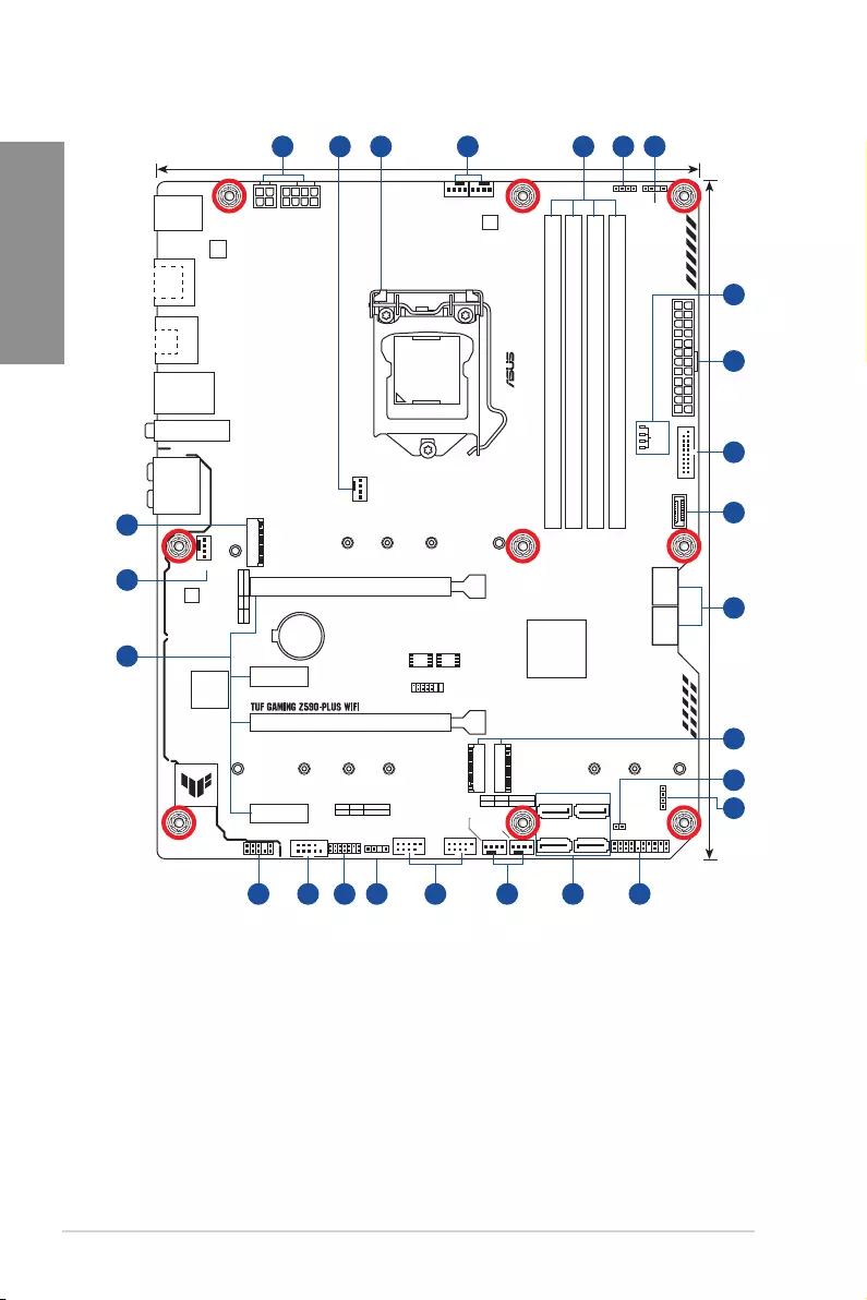
1.2 Motherboard layout
DDR4 DIMM_A1 (64bit, 288-pin module)
DDR4 DIMM_A2* (64bit, 288-pin module)
DDR4 DIMM_B1 (64bit, 288-pin module)
DDR4 DIMM_B2* (64bit, 288-pin module)
DIGI+
VRM
ASM
1442K
AIO_PUMP
CHA_FAN2
CHA_FAN3
CHA_FAN1
CPU_FAN CPU_OPT
CLRTC
M.2_1(SOCKET3)
M.2_2(SOCKET3)
M.2_3(SOCKET3)
RGB_HEADER1
PANEL
AAFP
SATA6G_1 SATA6G_2
SATA6G_3
128Mb
BIOS
64Mb
BIOS
SATA6G_4
SATA6G_5
RGB_HEADER2
ADD_GEN 2_2
SATA6G_6
ATX_12V_1ATX_12V_2
LGA1200
ATX_PWR
U32G1_910
Intel®
Z590
Intel®
I225-V
BATTERY
LAN_U32G2_34
CNVI(WIFI)
KBMS
_USB1112
HDMI
_DP
AUDIO
Super
I/O
PCIEX1_1
228022602242
2280
2280
22110
22110
2260 2242
22602242
PCIEX1_2
PCIEX16_2
PCIEX16_1
USB_E34USB_E12
M.2_2(SOCKET3)
PCIE SATA IRST
3.0 X4 PCH-attachedV
M.2_1(SOCKET3)
PCIE SATA IRST
4.0 X4 CPU-attachedX
M.2_3(SOCKET3) PCIE SATA IRST
3.0 X4 PCH-attached
V
COM TB_HEADER
U32G2X2_1
U32G1_78
24.4cm(9.6in)
30.5cm(12in)
U32_5
BOOT
VGA
DRAM
CPU
ADD_GEN 2_1
8
7
12
6
18
5
9
14 17 1115
3
5 214 11124
7
13
4 1610
4
6
TUF GAMING Z590-PLUS WIFI 1-3
Chapter 1
Layout contents Page
1. CPU socket 1-4
2. DIMM slots 1-5
3. Expansion slots 1-7
4. Fan and Pump headers 1-9
5. Power connectors 1-10
6. M.2 slots (SOCKET 3) 1-11
7. SATA 6Gb/s ports 1-12
8. USB 3.2 Gen 1 Front Panel connector 1-13
9. USB 3.2 Gen 1 header 1-14
10. USB 2.0 headers 1-15
11. AURA Addressable Gen2 headers 1-16
12. AURA RGB headers 1-17
13. Clear CMOS header 1-18
14. COM Port header 1-19
15. Front Panel Audio header 1-19
16. System Panel header 1-20
17. ThunderboltTM header 1-21
18. Q-LEDs 1-21
1-4 Chapter 1: Product Introduction
Chapter 1
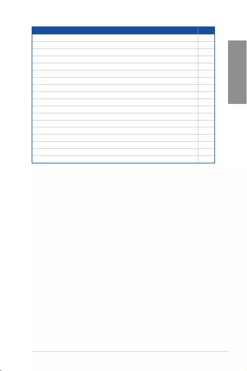
1. CPU socket
The motherboard comes with a LGA1200 socket designed for 11th Gen Intel® Core™
processors & 10th Gen Intel® Core™, Pentium® Gold and Celeron® Processors.
LGA1200
• Ensure that you install the correct CPU designed for LGA1200 socket only. DO NOT
install a CPU designed for other sockets on the LGA1200 socket.
• The CPU fits in only one correct orientation. DO NOT force the CPU into the socket
to prevent bending the connectors on the socket and damaging the CPU.
• Ensure that all power cables are unplugged before installing the CPU.
• Upon purchase of the motherboard, ensure that the PnP cap is on the socket and
the socket contacts are not bent. Contact your retailer immediately if the PnP cap
is missing, or if you see any damage to the PnP cap/socket contacts/motherboard
components. ASUS will shoulder the cost of repair only if the damage is shipment/
transit-related.
• Keep the cap after installing the motherboard. ASUS will process Return
Merchandise Authorization (RMA) requests only if the motherboard comes with the
cap on the LGA1200 socket.
• The product warranty does not cover damage to the socket contacts resulting from
incorrect CPU installation/removal, or misplacement/loss/incorrect removal of the
PnP cap.
TUF GAMING Z590-PLUS WIFI 1-5
Chapter 1
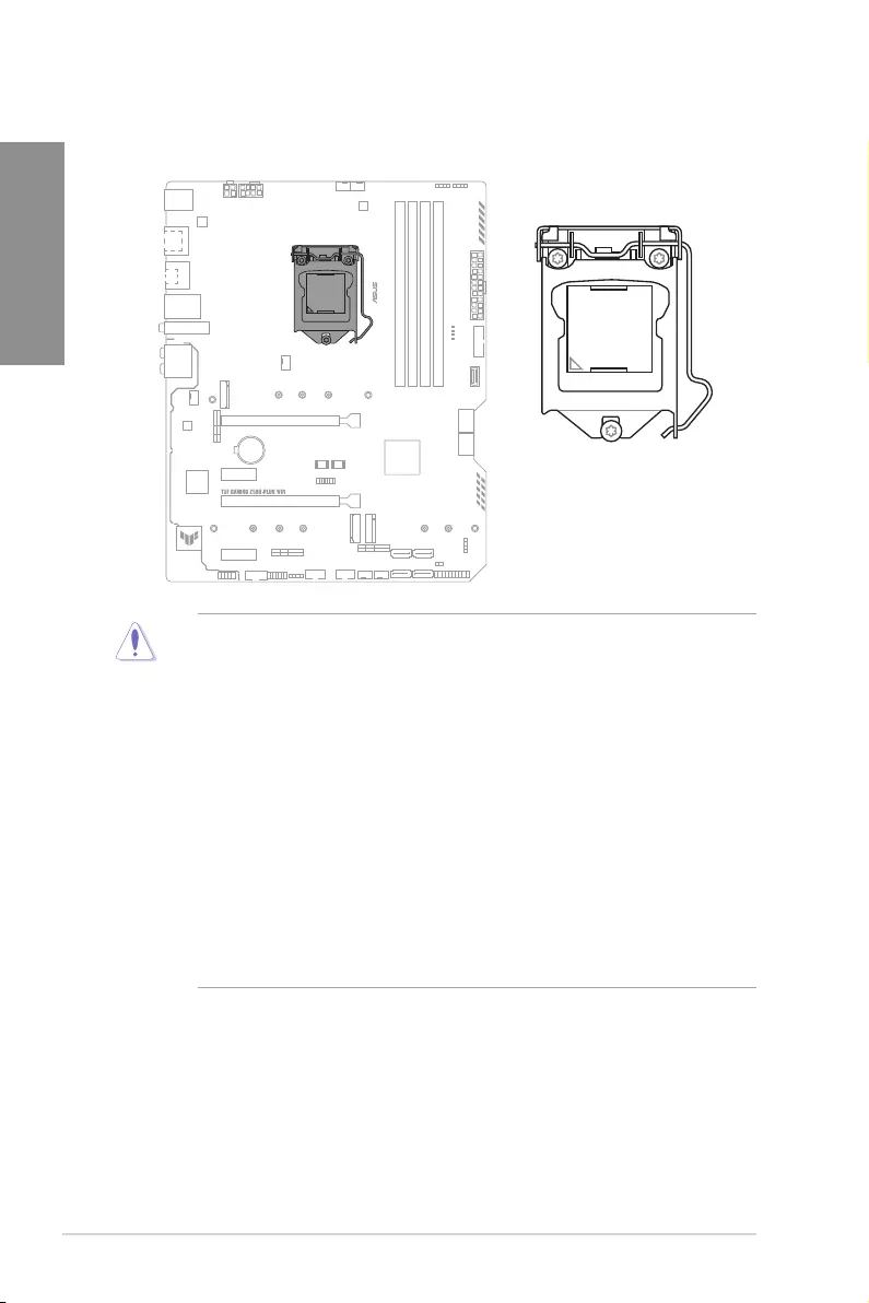
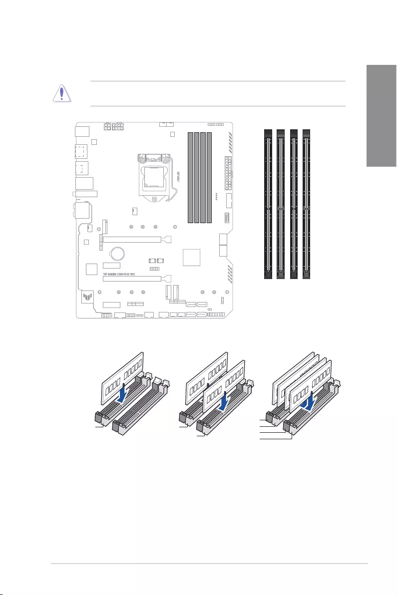
2. DIMM slots
The motherboard comes with Dual Inline Memory Modules (DIMM) slots designed for DDR4
(Double Data Rate 4) memory modules.
A DDR4 memory module is notched differently from a DDR, DDR2, or DDR3 module. DO
NOT install a DDR, DDR2, or DDR3 memory module to the DDR4 slot.
DIMM_A1
DIMM_A2*
DIMM_B1
DIMM_B2*
Recommended memory configurations
DIMM_A1
DIMM_A2*DIMM_A2*
DIMM_B2*
DIMM_A2*
DIMM_B1
DIMM_B2*

1-6 Chapter 1: Product Introduction
Chapter 1
Memory configurations
You may install 1 GB, 2 GB, 4 GB, 8 GB, 16 GB, and 32 GB unbuffered and non-ECC DDR4
DIMMs into the DIMM sockets.
You may install varying memory sizes in Channel A and Channel B. The system maps
the total size of the lower-sized channel for the dual-channel configuration. Any excess
memory from the higher-sized channel is then mapped for single-channel operation.
• The default memory operation frequency is dependent on its Serial Presence Detect
(SPD), which is the standard way of accessing information from a memory module.
Under the default state, some memory modules for overclocking may operate at a
lower frequency than the vendor-marked value.
• For system stability, use a more efficient memory cooling system to support a full
memory load or overclocking condition.
• Always install the DIMMS with the same CAS Latency. For an optimum compatibility,
we recommend that you install memory modules of the same version or data code
(D/C) from the same vendor. Check with the vendor to get the correct memory
modules.
• Refer to www.asus.com for the Memory QVL (Qualified Vendors Lists), and memory
frequency support depends on the CPU types.
TUF GAMING Z590-PLUS WIFI 1-7
Chapter 1
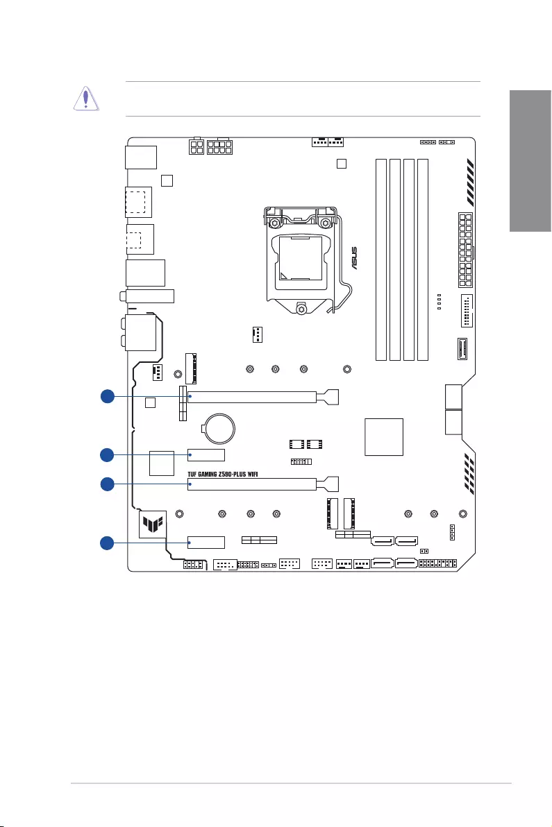
3. Expansion slots
Unplug the power cord before adding or removing expansion cards. Failure to do so may
cause you physical injury and damage motherboard components.
1
2
3
4
PCIEX1_1
PCIEX1_2
PCIEX16_2
PCIEX16_1
1-8 Chapter 1: Product Introduction
Chapter 1
Recommended VGA configuration
Slot Description Single VGA Dual VGA
1. PCIe 4.0 x16_1 x16 x16
3. PCIe 3.0 x16_2 — x4
Connect a chassis fan to the chassis fan connectors when using multiple graphics cards
for better thermal environment.
PCIe bifurcation & M.2 settings in PCIe x16 slots (from CPU)
PCIe bifurcation & M.2 settings in PCIe x16 slots (from CPU)
Slot Description Quantity of identifiable Intel M.2 SSD (pcs)
PCIe 4.0 x16_1 3 (x8+x4+x4)
M.2_1* 1 (x4)
• The Hyper M.2 X16 series card is sold separately.
• Ensure to install the Hyper M.2 X16 series card to PCIe 4.0 x16_1. If you wish to
connect a display, we suggest using the internal VGA or installing a VGA card to
PCIe 3.0 x16_2, which will run at x4.
• Enable the Hyper M.2 X16 series card under BIOS settings.
* Only support on Intel® 11th Gen processors
TUF GAMING Z590-PLUS WIFI 1-9
Chapter 1
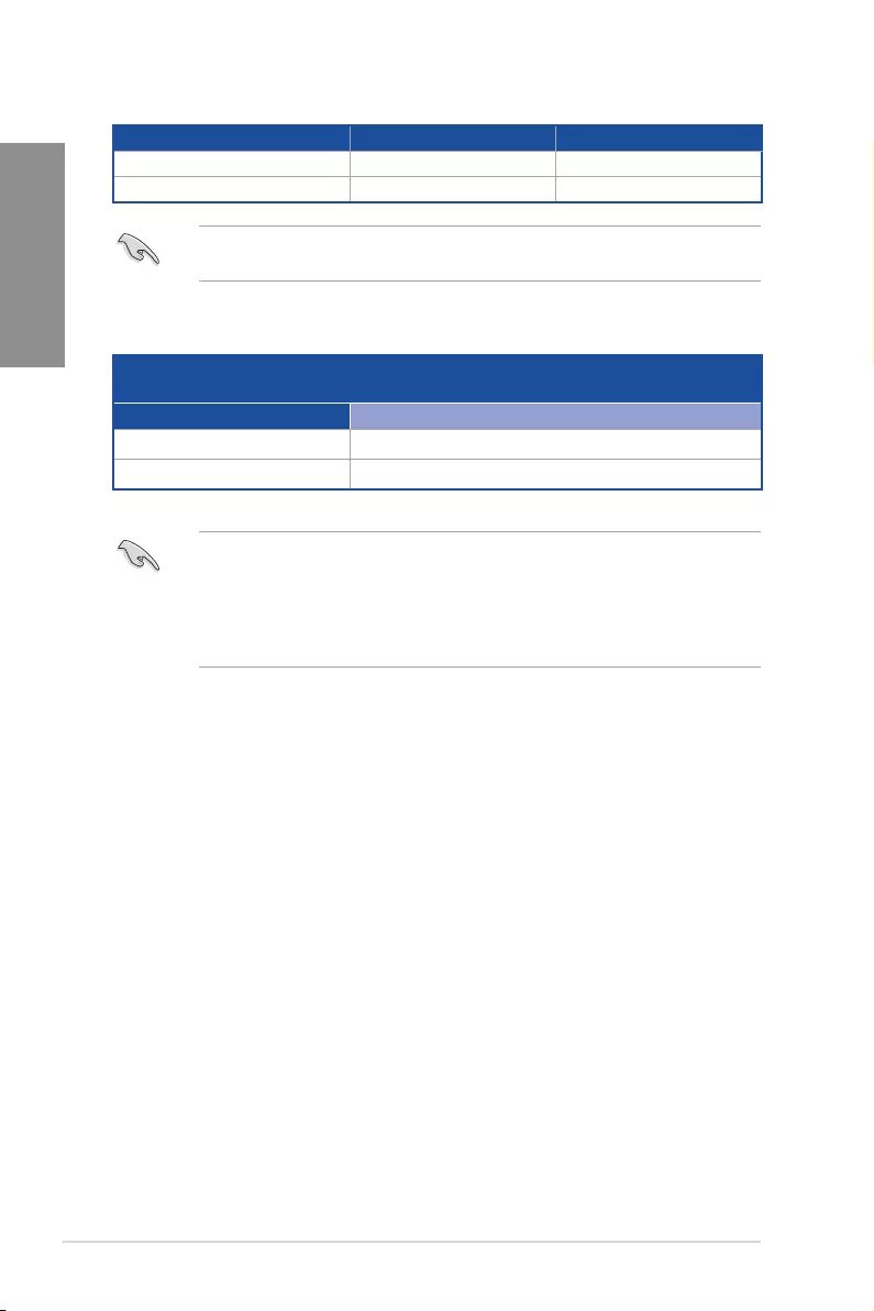
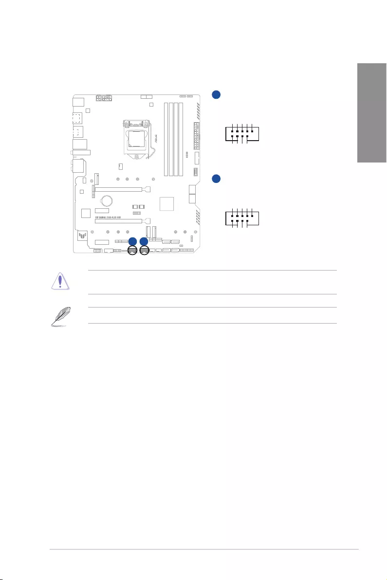
4. Fan and Pump headers
The Fan and Pump headers allow you to connect fans or pumps to cool the system.
FAN PWM
FAN IN
FAN PWR
GND
GND
FAN PWR
FAN IN
FAN PWM
GND
FAN PWR
FAN IN
FAN PWM
CPU_FAN
CPU_OPT
AIO_PUMP
CHA_FAN1
CHA_FAN2
CHA_FAN3
A B
A
B
C
E
D
F
C
E F
D
• DO NOT forget to connect the fan cables to the fan headers. Insufficient air flow inside
the system may damage the motherboard components. These are not jumpers! Do not
place jumper caps on the fan headers!
• Ensure the cable is fully inserted into the header.
Header Max. Current Max. Power Default Speed Shared Control
CPU_FAN 1A 12W Q-Fan Controlled A
CPU_OPT 1A 12W Q-Fan Controlled A
CHA_FAN1 1A 12W Q-Fan Controlled —
CHA_FAN2 1A 12W Q-Fan Controlled —
CHA_FAN3 1A 12W Q-Fan Controlled —
AIO_PUMP 1A 12W Full-Speed
1-10 Chapter 1: Product Introduction
Chapter 1
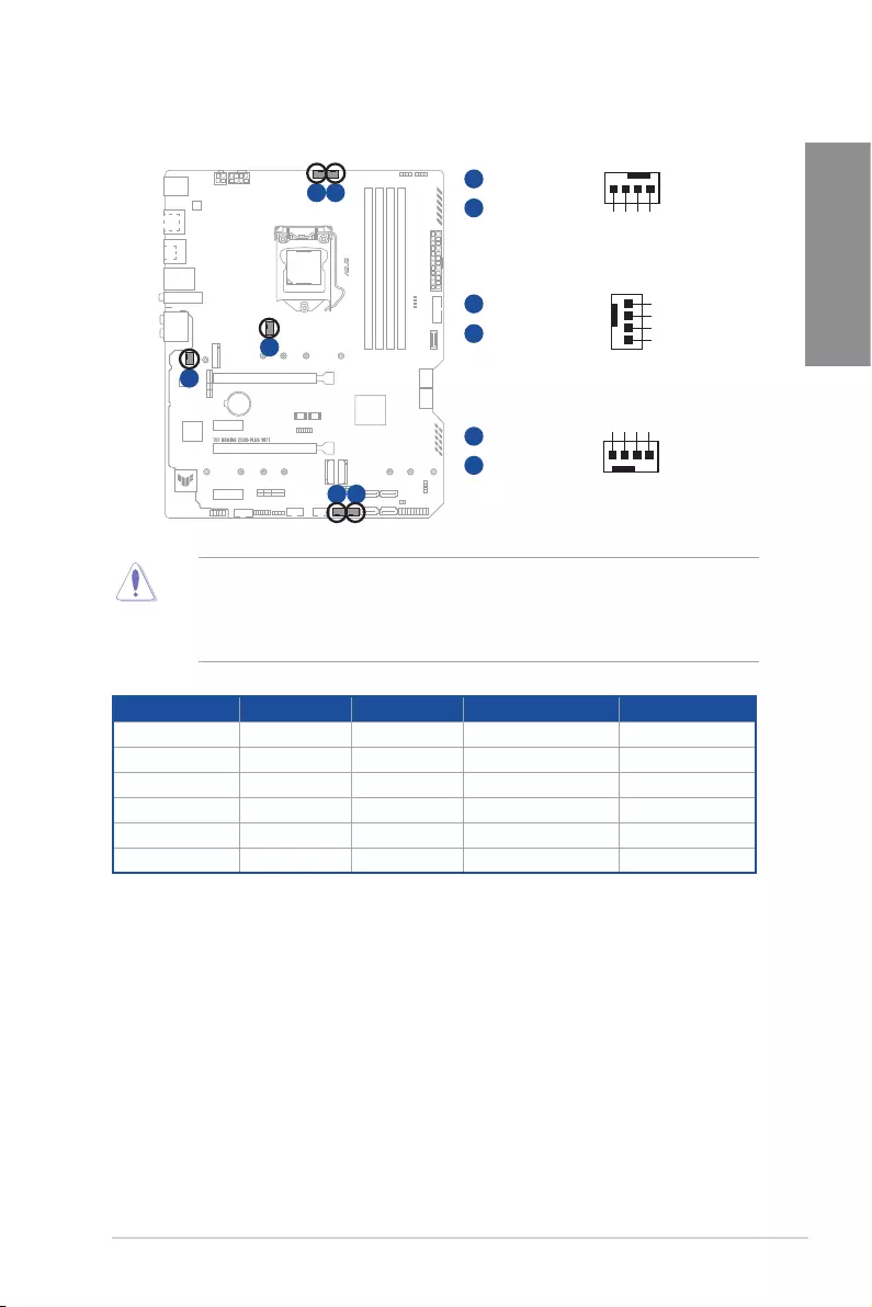
5. Power connectors
These Power connectors allow you to connect your motherboard to a power supply.
The power supply plugs are designed to fit in only one orientation. Find the proper
orientation and push down firmly until the power supply plugs are fully inserted.
A
A
C
B
B
ATX_12V_1
ATX_12V_2
+12V DC
+12V DC
+12V DC
+12V DC
GND
GND
GND
GND
ATX_PWR
PIN 1
PIN 1
GND
+5 Volts
+5 Volts
+5 Volts
-5 Volts
GND
GND
GND
PSON#
GND
-12 Volts
+3 Volts
+3 Volts
+12 Volts
+12 Volts
+5V Standby
Power OK
GND
+5 Volts
GND
+5 Volts
GND
+3 Volts
+3 Volts
C
PIN 1
GND
GND
+12V DC
+12V DC
Ensure to connect the 8-pin power plug.
• For a fully configured system, we recommend that you use a power supply unit
(PSU) that complies with ATX 12V Specification 2.0 (or later version) and provides a
minimum power of 350 W.
• We recommend that you use a PSU with a higher power output when configuring a
system with more power-consuming devices. The system may become unstable or
may not boot up if the power is inadequate.
• If you want to use two or more high-end PCI Express x16 cards, use a PSU with
1000W power or above to ensure the system stability.
TUF GAMING Z590-PLUS WIFI 1-11
Chapter 1
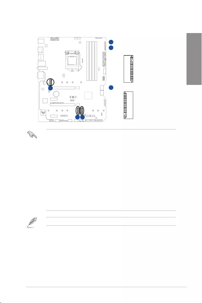
6. M.2 slots
The M.2 slots allow you to install M.2 devices such as M.2 SSD modules.
M.2_2(SOCKET3)
M.2_1(SOCKET3)
M.2_3(SOCKET3)
A
C
B
A
C
B
• M.2_1 slot (Key M), type 2242/2260/2280/22110 (Only Intel
®
11
th
Gen processors
support PCIe 4.0 x4 mode, this slot will be disabled for other CPUs).
• M.2_2 slot (Key M), type 2242/2260/2280/22110 (supports PCIe 3.0 x4 & SATA modes).
• M.2_3 slot (Key M), type 2242/2260/2280 (supports PCIe 3.0 x4 & SATA modes).
• M.2_2 shares bandwidth with SATA6G_2. When M.2_2 runs SATA mode, SATA6G_2
will be disabled.
• M.2_3 shares bandwidth with SATA6G_56. When M.2_3 is occupied, SATA6G_56
will be disabled.
• Raid function for PCIe mode SSD in Intel® Rapid Storage Technology is available
with either
1. Intel® SSDs installed in both CPU-attached and PCH-attached slots, or
2. any other 3rd party SSDs installed in PCH-attached slots.
• To enable Intel® Optane™ Memory (Hybrid Storage device), it must be installed in
PCH-attached slots with Intel® Rapid Storage Technology.
The M.2 SSD module is purchased separately.
1-12 Chapter 1: Product Introduction
Chapter 1
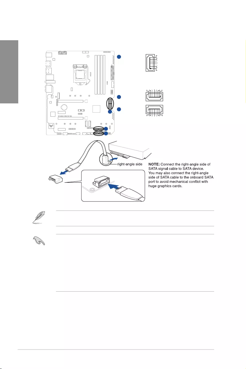
7. SATA 6Gb/s ports
The SATA 6Gb/s ports allow you to connect SATA devices such as optical disc drives
and hard disk drives via a SATA cable.
SATA6G_4
SATA6G_3
SATA6G_5
SATA6G_6
B
A
SATA6G_2
SATA6G_1
C
GND
RSATA_TXP
RSATA_TXN
GND
RSATA_RXN
RSATA_RXP
GND
GND
RSATA_TXP
RSATA_TXN
GND
RSATA_RXN
RSATA_RXP
GND
GND
RSATA_RXP
RSATA_RXN
GND
RSATA_TXN
RSATA_TXP
GND
B
A
C
If you installed SATA storage devices, you can create a RAID 0, 1, 5, and 10 configuration
with the Intel® Rapid Storage Technology through the onboard Intel® Z590 chipset.
• The slots are set to [AHCI Mode] by default. If you intend to create a SATA RAID set
using these connectors, set the SATA Mode item in the BIOS to [Intel RST Premium
With Intel Optane System Acceleration(RAID)].
• When a device in SATA mode is installed on the M.2_2 socket, SATA6G_2 port
cannot be used.
• When a device is installed on the M.2_3 socket, SATA6G_56 ports cannot be used.
• Before creating a RAID set, refer to the RAID Configuration Guide. You can
download the RAID Configuration Guide from the ASUS website.
TUF GAMING Z590-PLUS WIFI 1-13
Chapter 1
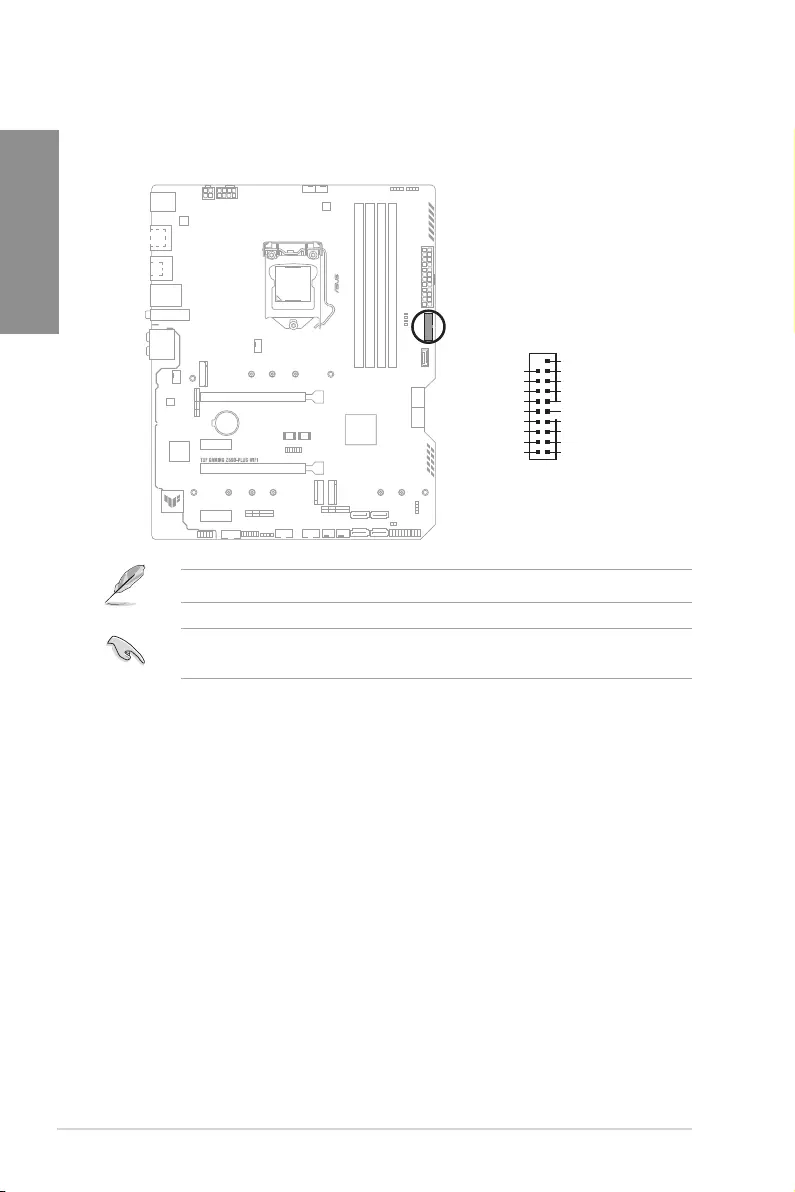
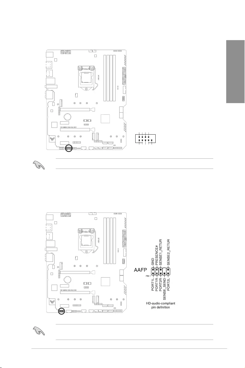
8. USB 3.2 Gen 1 Front Panel connector
The USB 3.2 Gen 1 connector (supports USB Type-C®) allows you to connect a USB
3.2 Gen 1 module for an additional USB 3.2 Gen 1 Type-C® port. The USB 3.2 Gen 1
connector provides data transfer speeds of up to 5 Gb/s.
U32_5
SBU2
SBU1
CC1
VBUS
RX1-
RX1+
GND
TX1-
TX1+
VBUS
VBUS
TX2+
TX2-
GND
RX2+
RX2-
GND
D-
D+
CC2
The USB 3.2 Gen 1 module is purchased separately.
1-14 Chapter 1: Product Introduction
Chapter 1
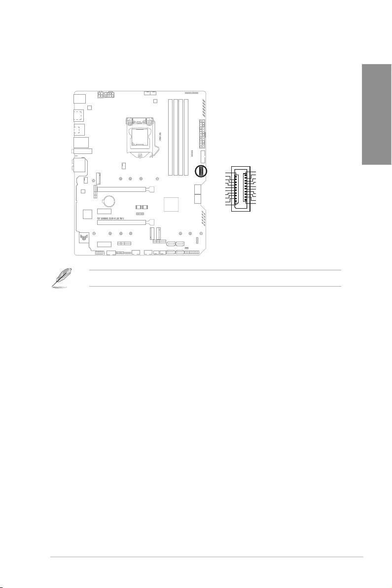
9. USB 3.2 Gen 1 header
The USB 3.2 Gen 1 header allows you to connect a USB 3.2 Gen 1 module for
additional USB 3.2 Gen 1 ports. The USB 3.2 Gen 1 header provides data transfer
speeds of up to 5 Gb/s.
U32G1_910
USB3+5V
IntA_P1_SSRX-
IntA_P1_SSRX+
GND
IntA_P1_SSTX-
IntA_P1_SSTX+
GND
IntA_P1_D-
IntA_P1_D+
GND
PIN 1
USB3+5V
IntA_P2_SSRX-
IntA_P2_SSRX+
GND
IntA_P2_SSTX-
IntA_P2_SSTX+
GND
IntA_P2_D-
IntA_P2_D+
A
The USB 3.2 Gen 1 module is purchased separately.
The plugged USB 3.2 Gen 1 device may run on xHCI or EHCI mode depending on the
operating system’s setting.
TUF GAMING Z590-PLUS WIFI 1-15
Chapter 1
10. USB 2.0 headers
Connect the USB module cable to these connectors, then install the module to a slot
opening at the front of the system chassis. These USB headers comply with USB 2.0
specifications and support up to 480 Mbps connection speed.
USB_E34
USB+5V
USB_P3-
USB_P3+
GND
NC
USB+5V
USB_P4-
USB_P4+
GND
PIN 1
USB_E12
USB+5V
USB_P1-
USB_P1+
GND
NC
USB+5V
USB_P2-
USB_P2+
GND
PIN 1
AB
A
B
DO NOT connect a 1394 cable to the USB connectors. Doing so will damage the
motherboard!
The USB 2.0 module is purchased separately.
1-16 Chapter 1: Product Introduction
Chapter 1
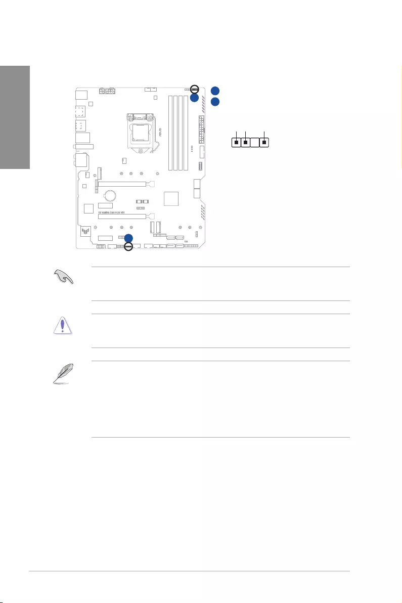
11. AURA Addressable Gen2 headers
The Addressable Gen2 headers allow you to connect individually addressable RGB
WS2812B LED strips or WS2812B based LED strips.
+5V
Data
Ground
PIN 1
ADD_GEN 2_1
ADD_GEN 2_2
A
A
B
B
The Addressable Gen2 headers support WS2812B addressable RGB LED strips (5V/
Data/Ground), with a maximum power rating of 3A (5V), and the addressable headers on
this board can handle a combined maximum of 500 LEDs.
Before you install or remove any component, ensure that the power supply is switched off
or the power cord is detached from the power supply. Failure to do so may cause severe
damage to the motherboard, peripherals, or components.
• Actual lighting and color will vary with LED strip.
• If your LED strip does not light up, check if the addressable RGB LED strip is
connected in the correct orientation, and the 5V connector is aligned with the 5V
header on the motherboard.
• The addressable RGB LED strip will only light up when the system is powered on.
• The addressable RGB LED strip is purchased separately.
TUF GAMING Z590-PLUS WIFI 1-17
Chapter 1
12. AURA RGB LED headers
The AURA RGB LED headers allow you to connect RGB LED strips.
RGB_HEADER2
RGB_HEADER1
PIN 1
+12V
G
R
B
PIN 1
+12V G R B
A
A
B
B
The AURA RGB LED headers support 5050 RGB multi-color LED strips (12V/G/R/B), with
a maximum power rating of 3A (12V).
Before you install or remove any component, ensure that the power supply is switched off
or the power cord is detached from the power supply. Failure to do so may cause severe
damage to the motherboard, peripherals, or components.
• Actual lighting and color will vary with LED strip.
• If your LED strip does not light up, check if the RGB LED extension cable and the
RGB LED strip is connected in the correct orientation, and the 12V connector is
aligned with the 12V header on the motherboard.
• The LED strip will only light up when the system is powered on.
• The LED strip is purchased separately.
1-18 Chapter 1: Product Introduction
Chapter 1
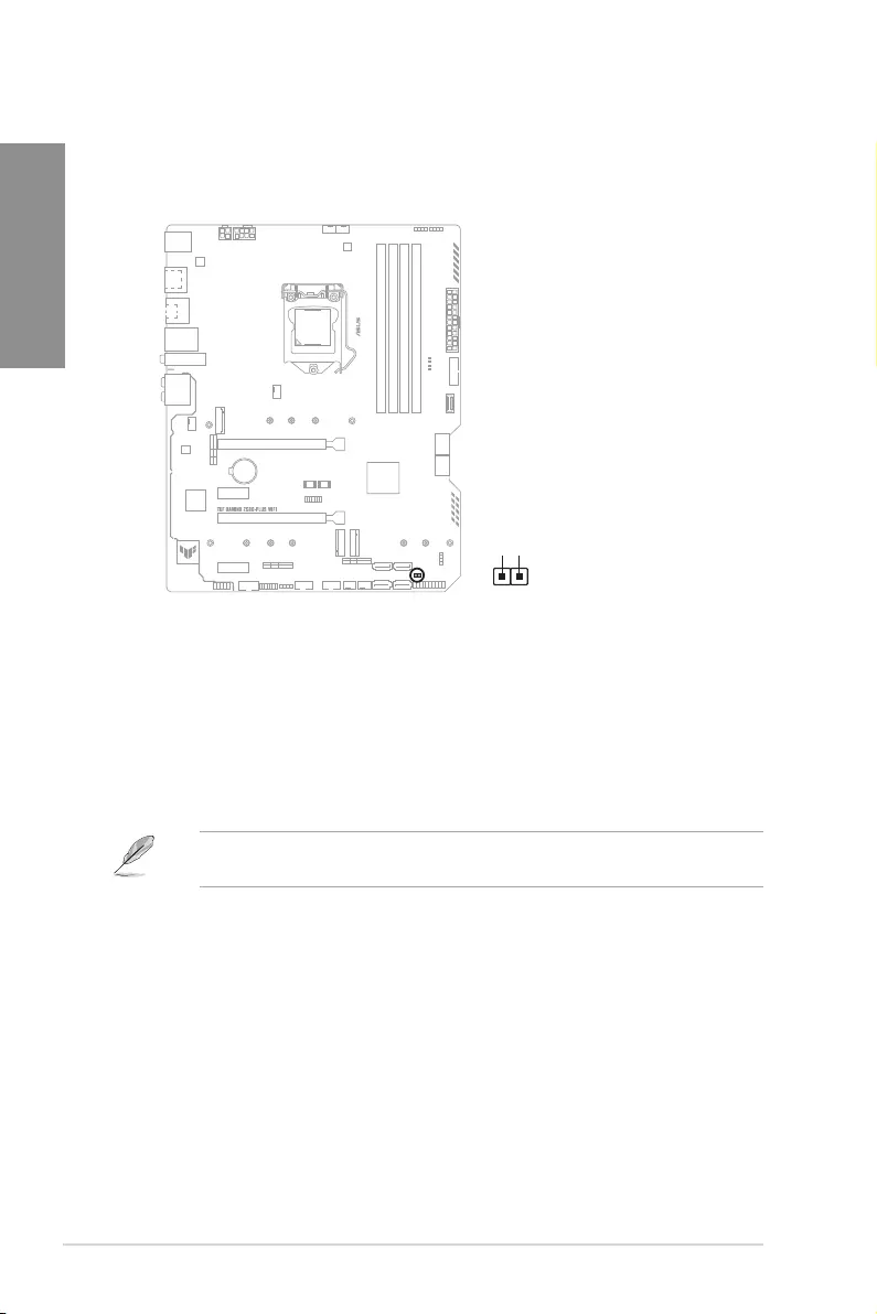
13. Clear CMOS header
This header allows you to clear the Real Time Clock (RTC) RAM in CMOS. You can
clear the CMOS memory of date, time, and system setup parameters by erasing the
CMOS RTC RAM data. The onboard button cell battery powers the RAM data in
CMOS, which include system setup information such as system passwords.
CLRTC
+3V_BAT
GND
PIN 1
To erase the RTC RAM:
1. Turn OFF the computer and unplug the power cord.
2. Use a metal object such as a screwdriver to short the two pins.
3. Plug the power cord and turn on the computer.
4. Hold down the <Del> key during the boot process and enter BIOS Setup to re-
enter data.
If the steps above do not help, remove the onboard battery and short the two pins again to
clear the CMOS RTC RAM data. After clearing the CMOS, reinstall the battery.
TUF GAMING Z590-PLUS WIFI 1-19
Chapter 1
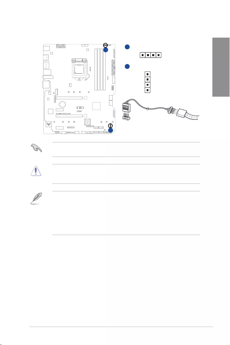
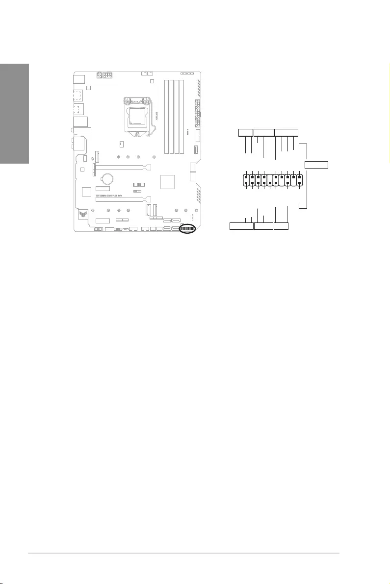
15. Front Panel Audio header
The front panel audio header is for a chassis-mounted front panel audio I/O module
that supports HD Audio. Connect one end of the front panel audio I/O module cable to
this header.
We recommend that you connect a high-definition front panel audio module to this
connector to avail of the motherboard’s high-definition audio capability.
14. COM Port header
This connector is for a serial (COM) port. Connect the serial port module cable to this
connector, then install the module to a slot opening at the back of the system chassis.
PIN 1
COM
DCD
TXD
GND
RTS
RI
RXD
DTR
DSR
CTS
The COM module is purchased separately.
1-20 Chapter 1: Product Introduction
Chapter 1
16. System Panel header
The System Panel header supports several chassis-mounted functions.
PLED
PLED
SPEAKER
CHASSIS
HDD_LED
PWRSW
RESET
PIN 1
PLED+
PLED-
PWRBTN#
GND
+5V
Ground
Ground
Speaker
Intruder#
HDD_LED+
HDD_LED-
Ground
RSTCON#
NC
PLED+
PLED-
GND
PANEL
• System Power LED header (PLED)
The 2-pin header allows you to connect the System Power LED. The System Power
LED lights up when the system is connected to a power source, or when you turn on
the system power, and blinks when the system is in sleep mode.
• Storage Device Activity LED header (HDD_LED)
The 2-pin header allows you to connect the Storage Device Activity LED. The Storage
Device Activity LED lights up or blinks when data is read from or written to the storage
device or storage device add-on card.
• System Warning Speaker header (SPEAKER)
The 4-pin header allows you to connect the chassis-mounted system warning
speaker. The speaker allows you to hear system beeps and warnings.
• Power Button/Soft-off Button header (PWRSW)
The 3-1 pin header allows you to connect the system power button. Press the
power button to power up the system, or put the system into sleep or soft-off mode
(depending on the operating system settings).
• Reset button header (RESET)
The 2-pin header allows you to connect the chassis-mounted reset button. Press the
reset button to reboot the system.
• Chassis intrusion header (2-pin CHASSIS)
This header is for a chassis-mounted intrusion detection sensor or switch. Connect
one end of the chassis intrusion sensor or switch cable to this header. The chassis
intrusion sensor or switch sends a high-level signal to this connector when a chassis
component is removed or replaced. The signal is then generated as a chassis
intrusion event.
TUF GAMING Z590-PLUS WIFI 1-21
Chapter 1
17. ThunderboltTM header
The ThunderboltTM header allows you to connect an add-on ThunderboltTM I/O card
that supports Intel’s ThunderboltTM Technology, allowing you to connect up to six
ThunderboltTM-enabled devices and a DisplayPort-enabled display in a daisy-chain
configuration.
PIN 1
FORCE_PWR
GND
SLP_S3#
SLP_S5#
GND
RTD3_SW
I2C_SCL
I2C_SDA
I2C_IRQ#
RTD3_POWER_EN
S_SLP_S0#_IDLE
PERST_N
WAKE#
TB_HEADER
• The add-on Thunderbolt
TM
I/O card and Thunderbolt
TM
cables are purchased separately.
• Please visit the official website of your purchased ThunderboltTM card for more details
on compatibility.
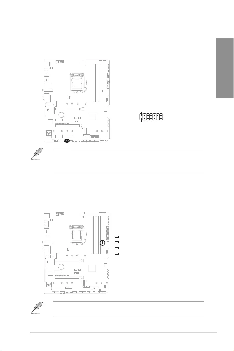
18. Q-LEDs
The Q-LEDs check key components (CPU, DRAM, VGA, and booting devices) during
the motherboard booting process. If an error is found, the critical component’s LED
stays lit up until the problem is solved.
BOOT (YELLOW GREEN)
VGA (WHITE)
DRAM (YELLOW)
CPU (RED)
The Q-LEDs provide the most probable cause of an error code as a starting point for
troubleshooting. The actual cause may vary from case to case.

1-22 Chapter 1: Product Introduction
Chapter 1
TUF GAMING Z590-PLUS WIFI 2-1
Chapter 2
2
Basic Installation
2.1 Building your PC system
The diagrams in this section are for reference only. The motherboard layout may vary with
models, but the installation steps are the same for all models.
Chapter 2: Basic Installation
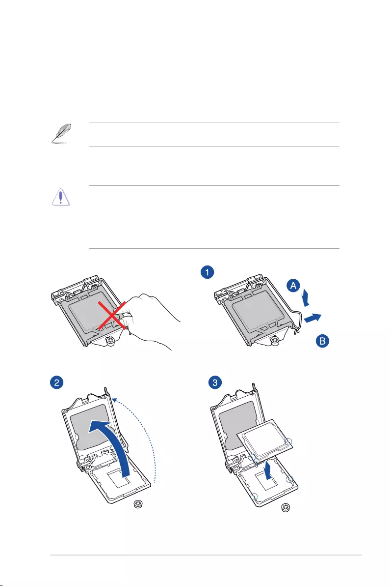
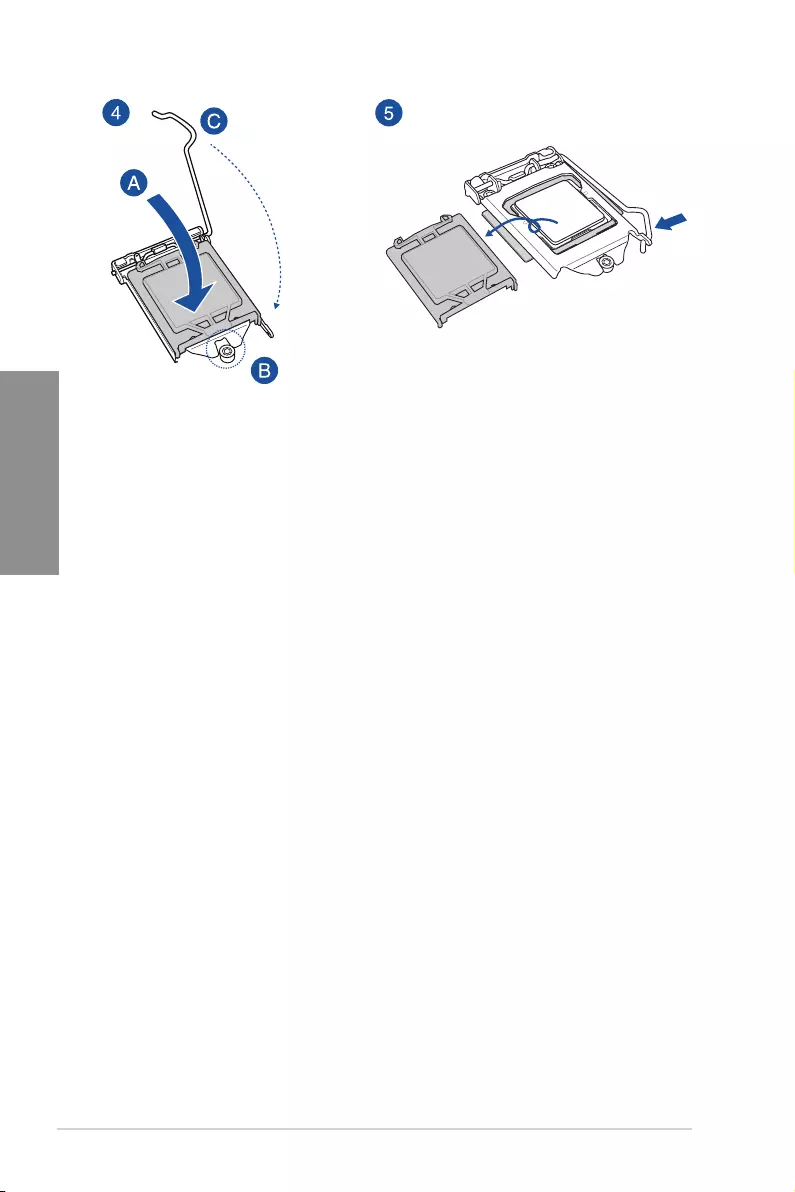
2.1.1 CPU installation
• Ensure that you install the correct CPU designed for LGA1200 socket only. DO
NOT install a CPU designed for LGA1155, LGA1156, and LGA1151 sockets on the
LGA1200 socket.
• ASUS will not cover damages resulting from incorrect CPU installation/removal,
incorrect CPU orientation/placement, or other damages resulting from negligence by
the user.
2-2 Chapter 2: Basic Installation
Chapter 2
TUF GAMING Z590-PLUS WIFI 2-3
Chapter 2
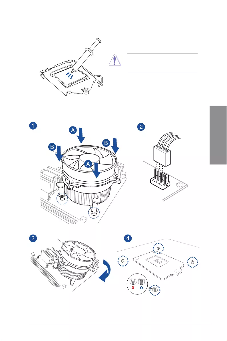
2.1.2 Cooling system installation
To install a CPU heatsink and fan assembly
Apply Thermal Interface Material to the
CPU cooling system and CPU before you
install the cooling system, if necessary.
2-4 Chapter 2: Basic Installation
Chapter 2
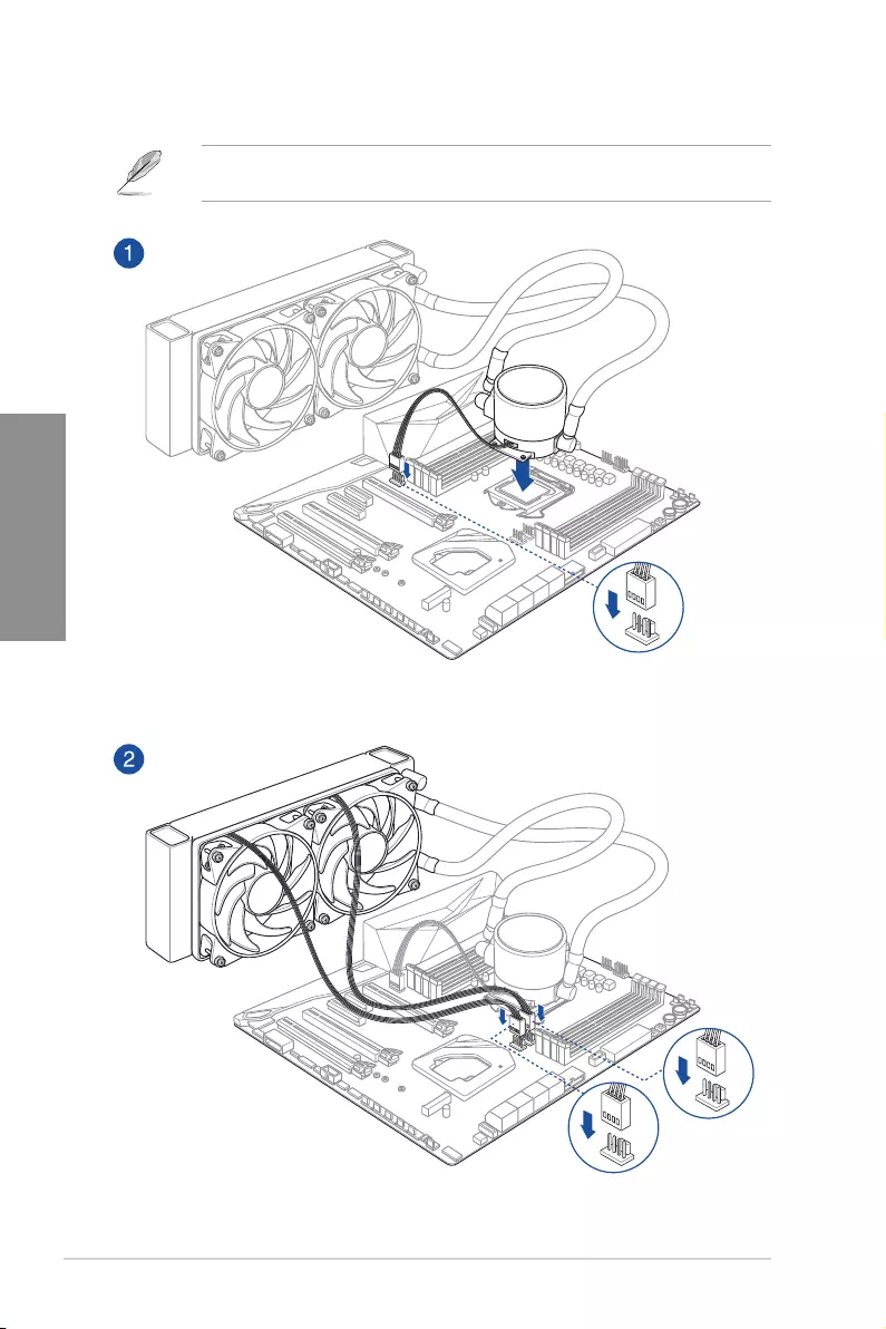
AIO_PUMP
CPU_OPT
CPU_FAN
To install an AIO cooler
If you wish to install an AIO cooler, we recommend installing the AIO cooler after installing
the motherboard into the chassis.
TUF GAMING Z590-PLUS WIFI 2-5
Chapter 2
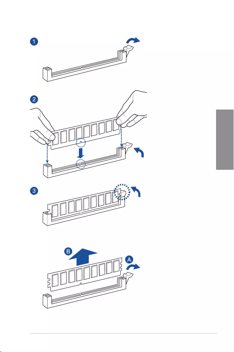
2.1.3 DIMM installation
To remove a DIMM
2-6 Chapter 2: Basic Installation
Chapter 2
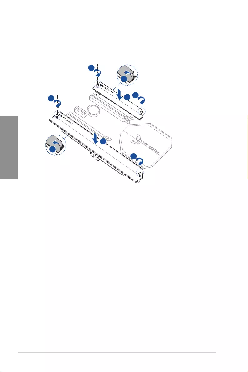
2.1.4 M.2 installation
Supported M.2 type varies per motherboard.
• The illustrations only show the installation steps for a single M.2 slot, the steps are
the same for the other M.2 slots if you wish to install an M.2 to another M.2 slot.
• Use a Phillips screwdriver when removing or installing the screws or screw stands
mentioned in this section.
• The M.2 is purchased separately.
When installing an M.2 to the M.2 slot, you may need to use the removable screw stand.
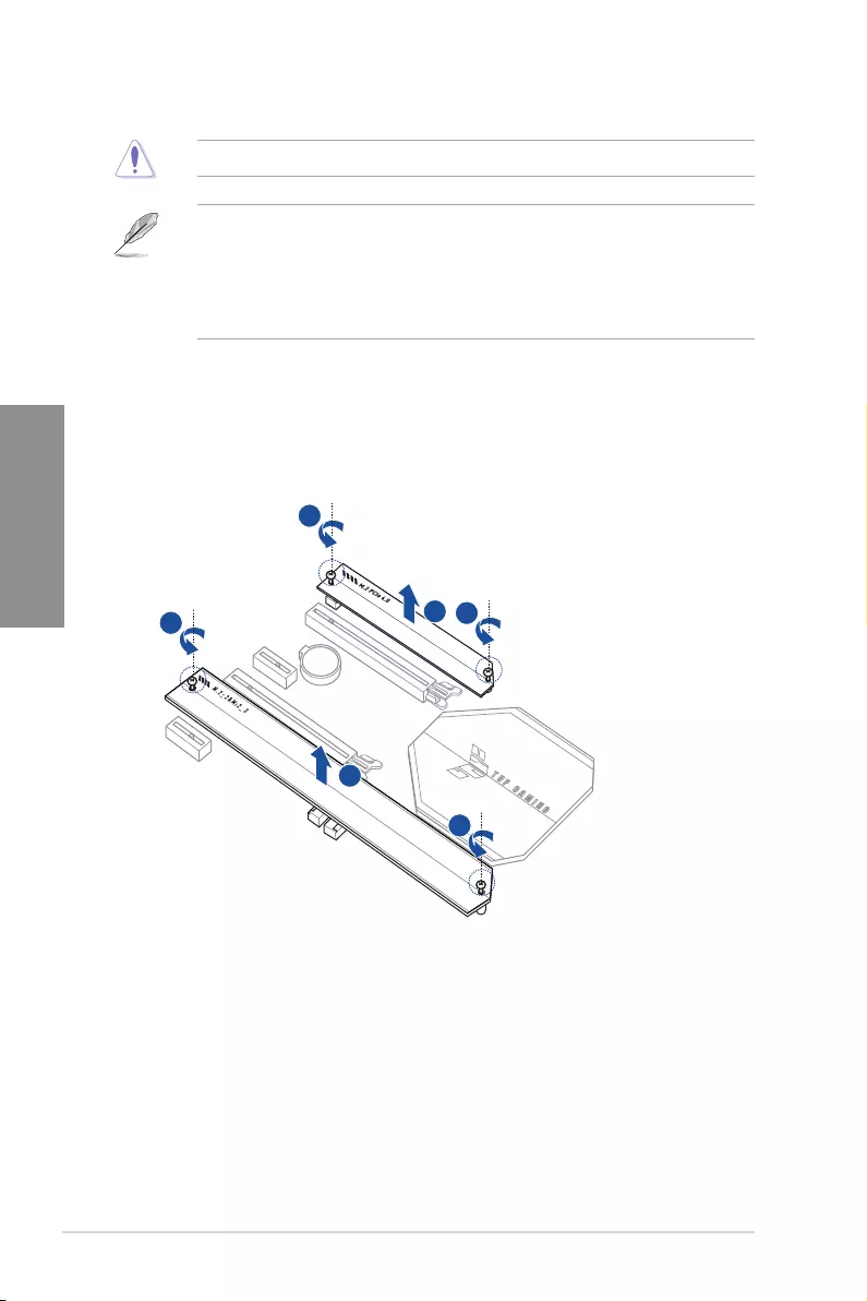
1. Remove the screws from the heatsink.
2. Remove the heatsink.
2
2
1
1
1
1
TUF GAMING Z590-PLUS WIFI 2-7
Chapter 2
3. Install your M.2 to your M.2 slot.
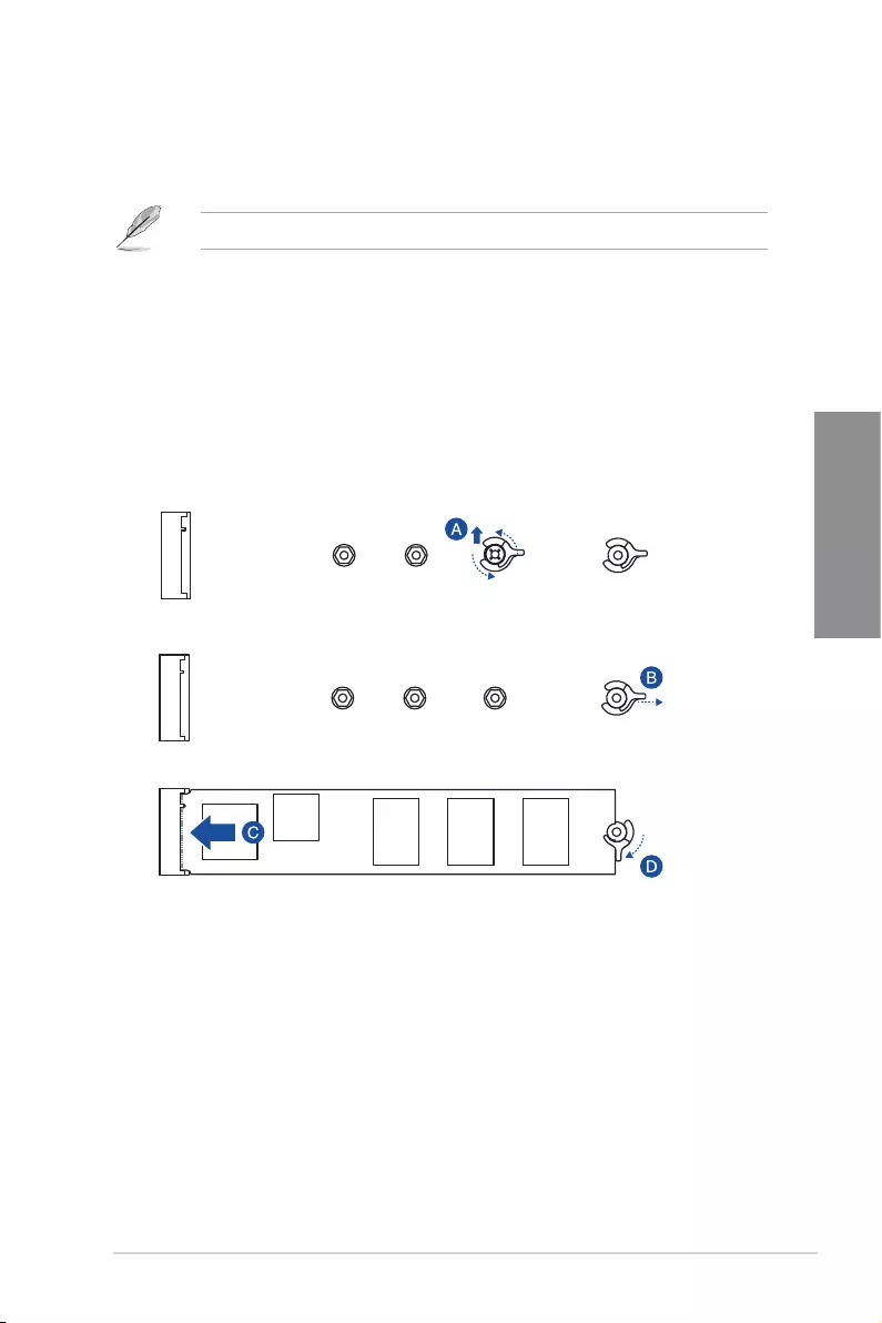
For M.2_1
• To install an M.2 to the maximum length
For M.2_1: Type 22110 M.2
A. (optional) Remove the pre-installed removable M.2 Q-Latch screw at the 2280
length screw hole.
B. Rotate and adjust the M.2 Q-latch so that the handle points away from the M.2
slot.
C. Install your M.2 to the M.2 slot.
D. Rotate the M.2 Q-Latch towards the right to secure the M.2 in place.
2-8 Chapter 2: Basic Installation
Chapter 2
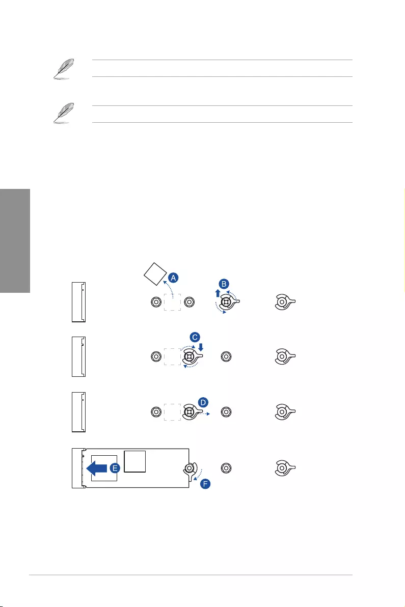
• To install an M.2 using the removable M.2 Q-Latch screw
For M.2_1: Type 2242, 2260, 2280 M.2
A. (optional) Remove the M.2 rubber pad.
Follow this step only if you wish to install an M.2 to type 2242.
B. (optional) If required, remove the pre-installed removable M.2 Q-Latch screw at
the 2280 length screw hole.
C. Install the M.2 Q-Latch to the M.2 length screw hole you wish to install your M.2
to.
D. Rotate and adjust the M.2 Q-latch so that the handle points away from the M.2
slot.
E. Install your M.2 to the M.2 slot.
F. Rotate the M.2 Q-Latch towards the right to secure the M.2 in place.
TUF GAMING Z590-PLUS WIFI 2-9
Chapter 2
For M.2_2 and M.2_3
The steps may differ between installing M.2 of different lengths, please refer to the
different types and their installation steps below:
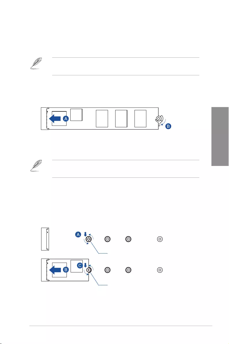
• To install an M.2 to the maximum length the M.2 slot supports
For M.2_2: Type 22110 M.2
For M.2_3: Type 2280 M.2
A. Install your M.2 to the M.2 slot.
B. Rotate the M.2 Q-Latch towards the right to secure the M.2 in place.
• To install an M.2 using the removable screw stand
For M.2_2: Type 2242, 2260, 2280 M.2
For M.2_3: Type 2242, 2260 M.2
A. Install the bundled removable screw stand to the M.2 length screw hole you wish
to install your M.2 to.
B. Install your M.2 to the M.2 slot.
C. Secure your M.2 using the bundled removable screw stand’s screw.
Removable screw stand
Removable screw stand’s screw
2-10 Chapter 2: Basic Installation
Chapter 2
4. Remove the plastic film from the thermal pads on the bottom of the heatsink.
5. Replace the heatsink.
6. Secure the heatsink using the screws removed previously.
4
4
6
6
6
6
5
5
TUF GAMING Z590-PLUS WIFI 2-11
Chapter 2
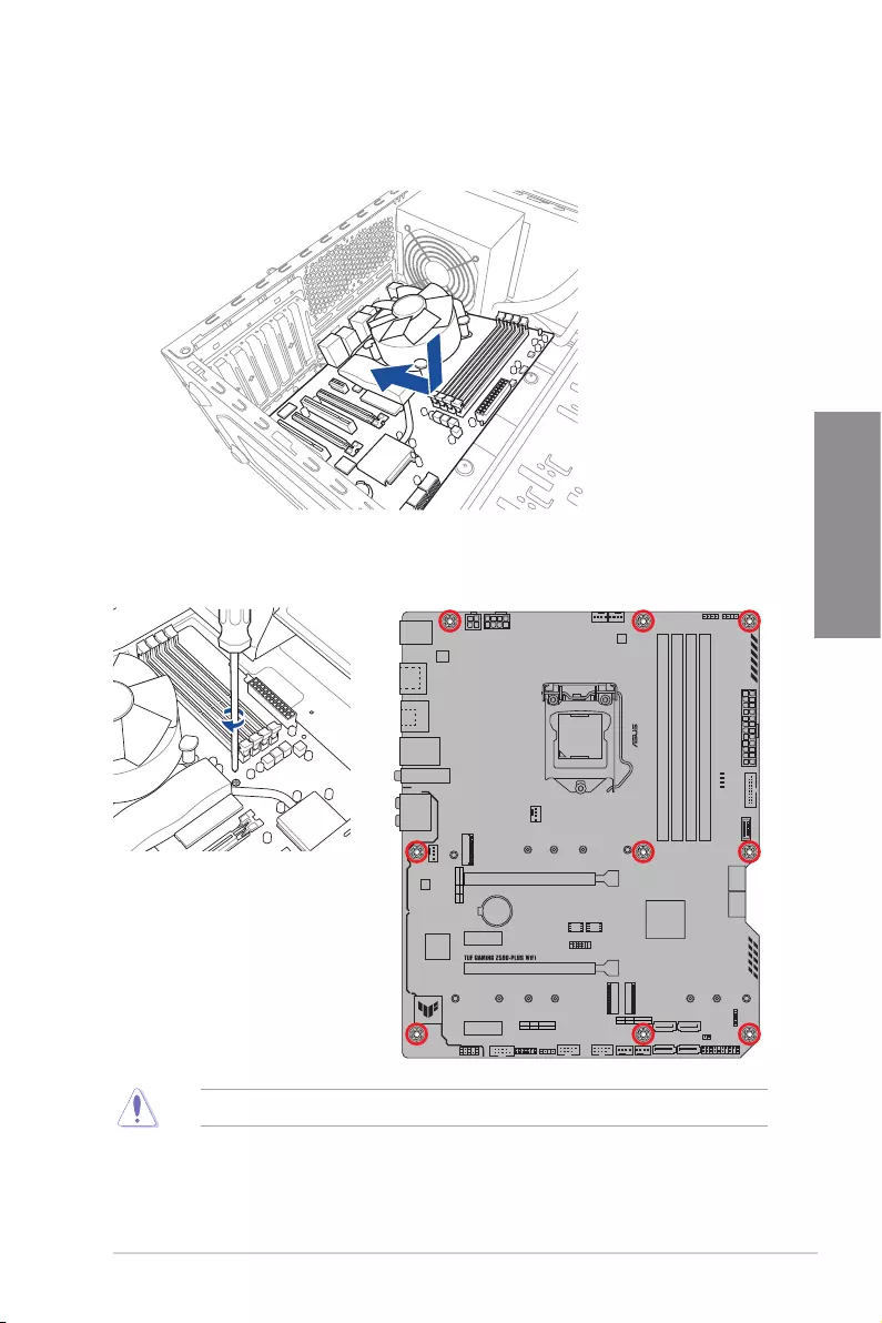
1. Place the motherboard into the chassis, ensuring that its rear I/O ports are aligned to
the chassis’ rear I/O panel.
2.1.5 Motherboard installation
2. Place nine (9) screws into the holes indicated by circles to secure the motherboard to
the chassis.
DO NOT over tighten the screws! Doing so can damage the motherboard.
2-12 Chapter 2: Basic Installation
Chapter 2
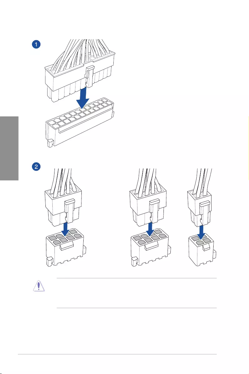
2.1.6 ATX power connection
OR AND
• DO NOT connect the 4-pin power plug only, the motherboard may overheat under
heavy usage.
• Ensure to connect the 8-pin power plug, or connect both the 8-pin and 4-pin power
plugs.
TUF GAMING Z590-PLUS WIFI 2-13
Chapter 2
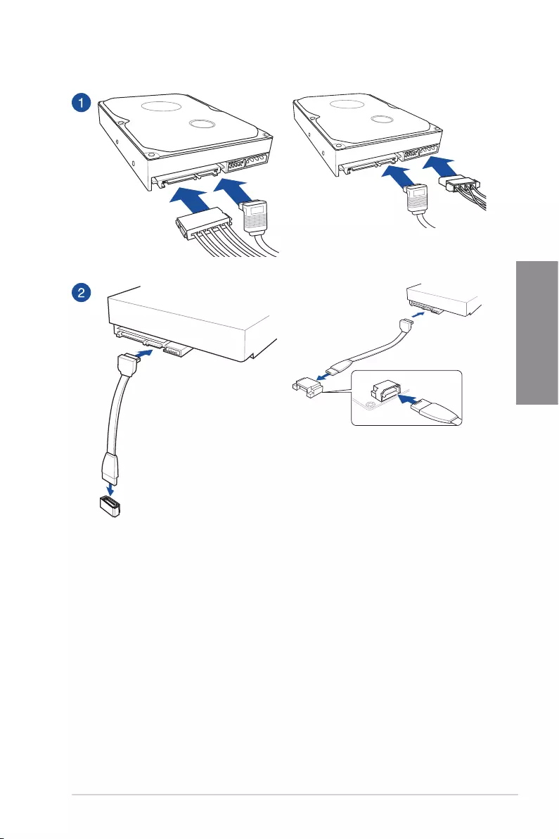
2.1.7 SATA device connection
OR
OR
2-14 Chapter 2: Basic Installation
Chapter 2
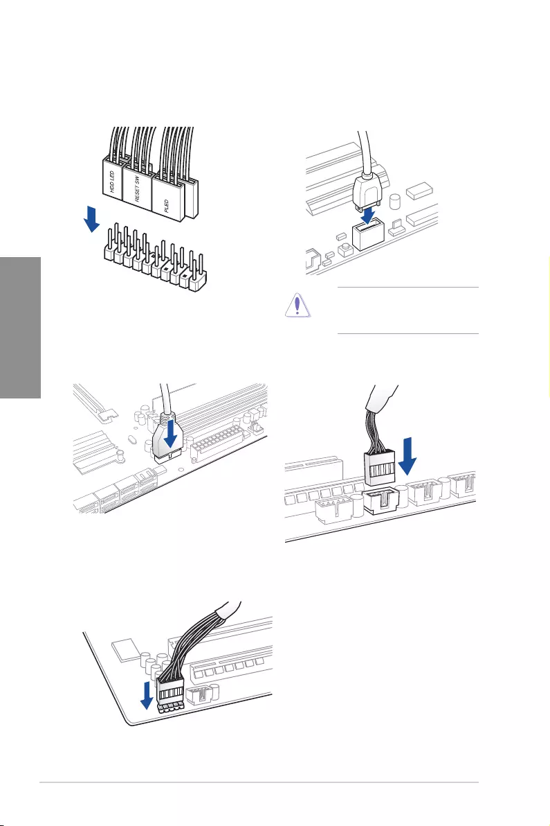
2.1.8 Front I/O connectors
USB 3.2 Gen 1 (USB Type-C®)
To install USB 3.2 Gen 1 connector
(USB Type-C®)
This connector will only fit in one
orientation. Push the connector
until it clicks into place.
USB 2.0
AAFP
To install USB 2.0 connector
To install front panel audio connector
USB 3.2 Gen 1
To install USB 3.2 Gen 1 connector
To install the front panel header
TUF GAMING Z590-PLUS WIFI 2-15
Chapter 2
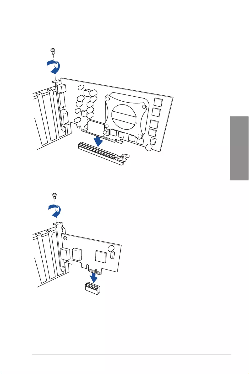
2.1.9 Expansion card installation
To install PCIe x16 cards
To install PCIe x1 cards
2-16 Chapter 2: Basic Installation
Chapter 2
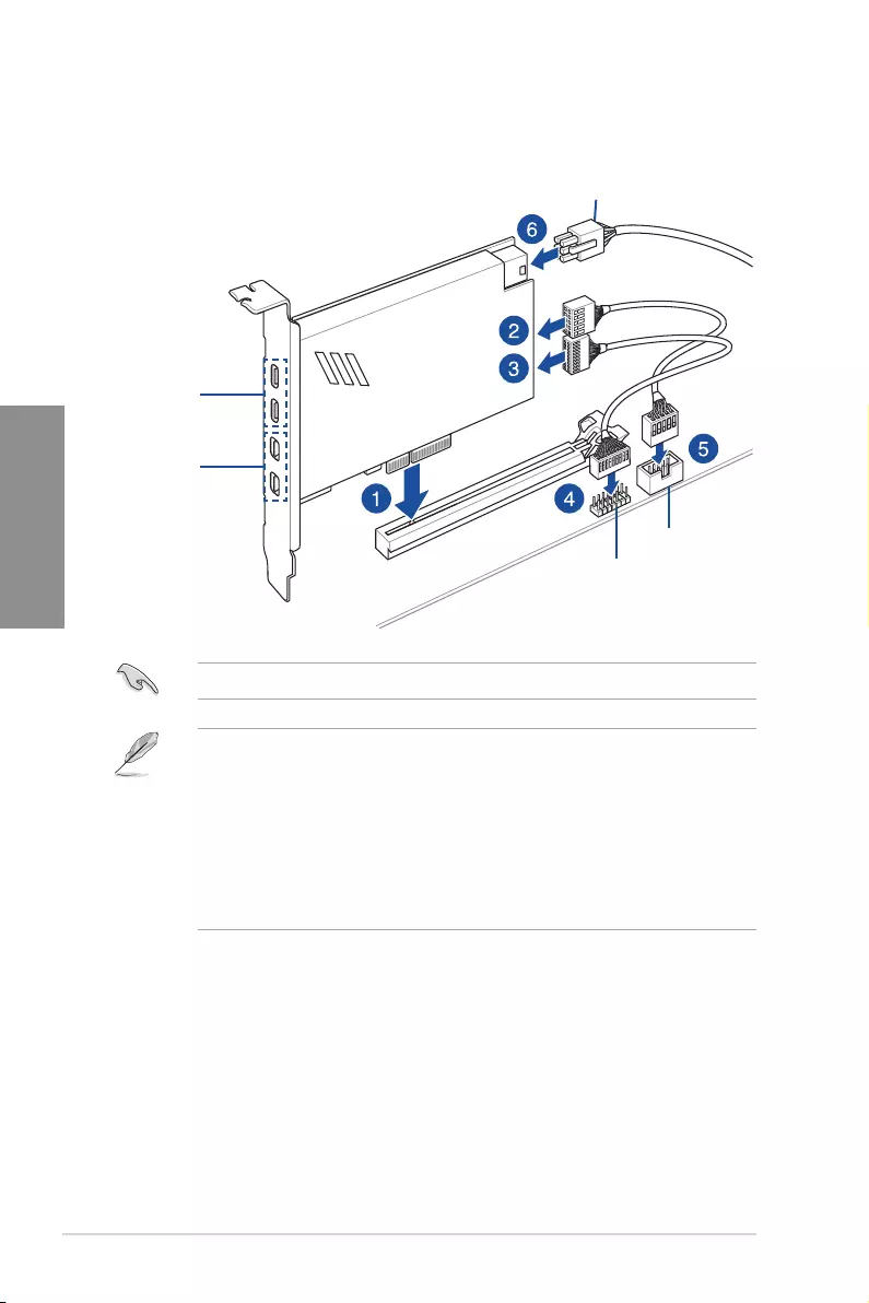
ThunderboltTM header
USB Type-C®
port connects to
ThunderboltTM
devices
MiniDP in port
connects to DP
out port on the
motherboard
or a VGA card
USB 2.0 header
6-pin PCIe power connector
Ensure to install the ThunderboltTM series card to a PCIe slot from PCH.
• Step 6 is optional, please connect a 6-pin PCIe power connector when you wish to
use the USB Type-C® port ThunderboltTM quick charge feature to charge a 5V or
more device.
• The TypeC_1 port can support up to 20V devices, and the TypeC_2 port can support
up to 9V devices when the 6-pin PCIe power connector is connected.
• The ThunderboltTM card is sold separately.
• Please visit the official website of your purchased ThunderboltTM card for more details
on compatibility.
To install ThunderboltTM series card
TUF GAMING Z590-PLUS WIFI 2-17
Chapter 2
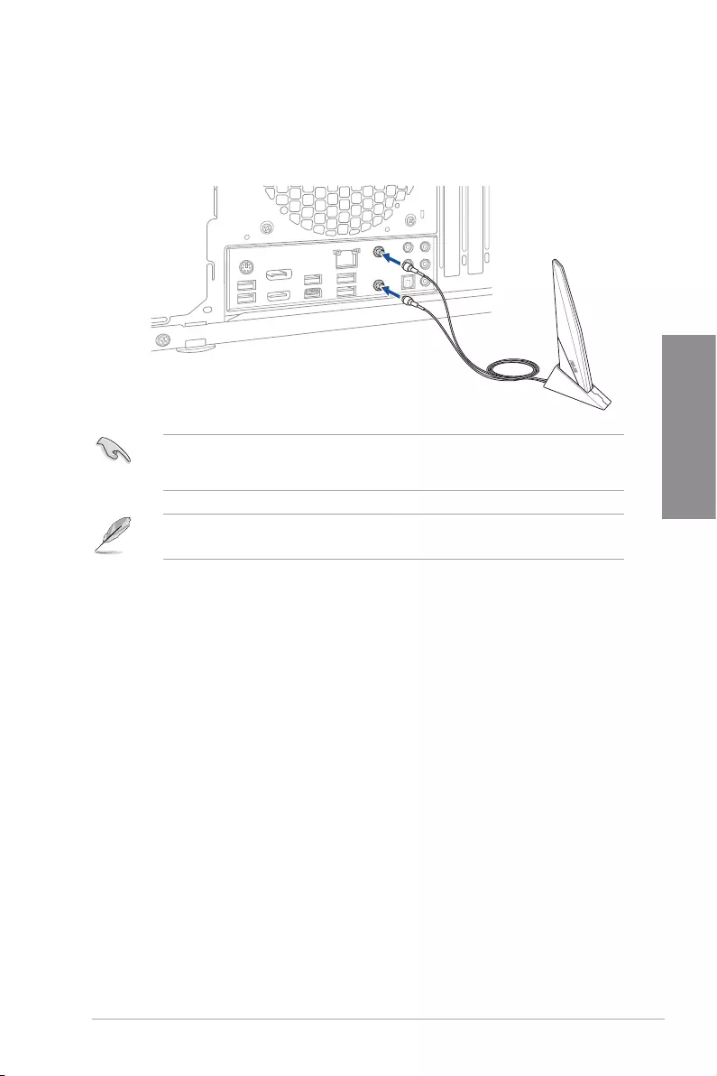
2.1.10 Wi-Fi antenna installation
Installing the ASUS Wi-Fi antennas
Connect the bundled ASUS Wi-Fi antennas connector to the Wi-Fi ports at the back of the
chassis.
• Ensure that the ASUS Wi-Fi antennas are securely installed to the Wi-Fi ports.
• Ensure that the antennas are at least 20 cm away from all persons.
The illustration above is for reference only. The I/O port layout may vary with models, but
the Wi-Fi antennas installation procedure is the same for all models.
2-18 Chapter 2: Basic Installation
Chapter 2
2.2 Motherboard rear and audio connections
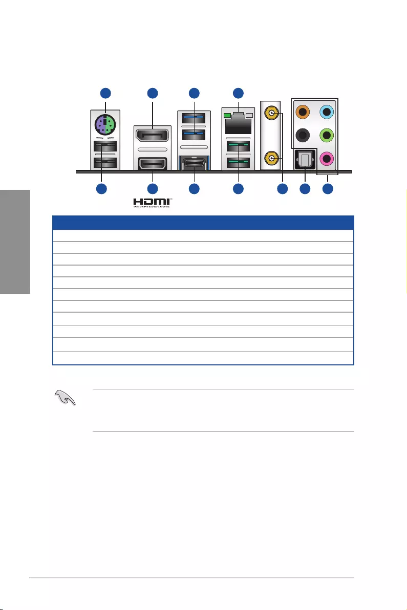
2.2.1 Rear I/O connection
Rear panel connectors
1. PS/2 mouse/keyboard combo port
2. DisplayPort
3. USB 3.2 Gen 1 Type-A ports
4. Ethernet (RJ-45) port*
5. USB 2.0 Type-A ports
6. HDMI™ port
7. USB 3.2 Gen 2×2 port (USB Type-C®)
8. USB 3.2 Gen 2 Type-A ports
9. Wi-Fi module
10. Optical S/PDIF OUT port
11. Audio jacks**
* and ** : Refer to the tables on the next page for LAN port LEDs, and audio port definitions.
We strongly recommend that you connect your devices to ports with matching data transfer
rate. Please connect your USB 3.2 Gen 1 devices to USB 3.2 Gen 1 ports and your USB
3.2 Gen 2 devices to USB 3.2 Gen 2 ports for faster and better performance for your
devices.
4
8 95
3
7 11106
21
TUF GAMING Z590-PLUS WIFI 2-19
Chapter 2
** Audio 2, 4, 5.1 or 7.1-channel configuration
Port Headset
2-channel 4-channel 5.1-channel 7.1-channel
Light Blue Line In Line In Line In Side Speaker Out
Lime Line Out Front Speaker Out Front Speaker Out Front Speaker Out
Pink Mic In Mic In Mic In Mic In
Orange – –
Center/Sub woofer Center/Sub woofer
Black – Rear Speaker Out Rear Speaker Out Rear Speaker Out
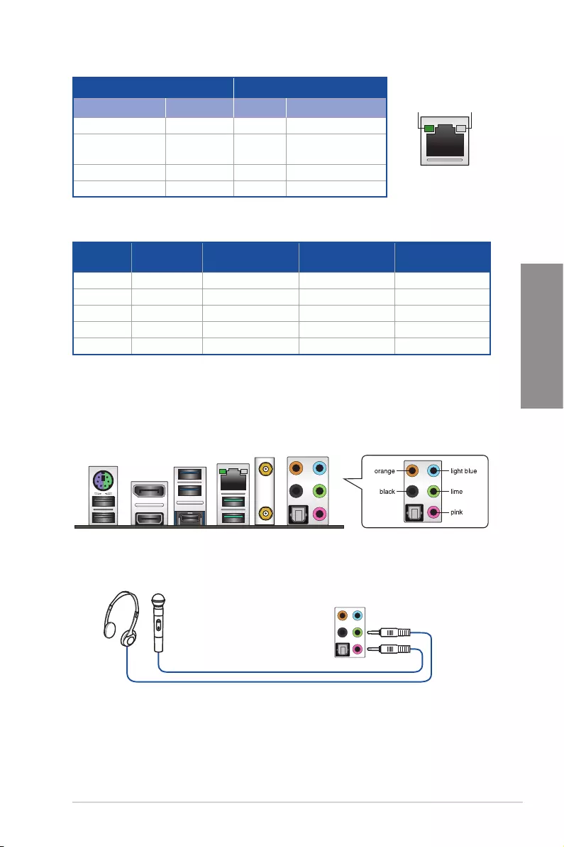
* Intel® I225-V 2.5Gb Ethernet port LED indications
2.2.2 Audio I/O connections
Audio I/O ports
Connect to Headphone and Mic
ACT/LINK
LED SPEED
LED
LAN port
Activity Link LED Speed LED
Status Description Status Description
OFF No link OFF No link
GREEN BLINKING Data activity OFF 100 Mbps / 10 Mbps
connection
GREEN BLINKING Data activity GREEN 2.5 Gbps connection
GREEN BLINKING Data activity ORANGE 1 Gbps connection
2-20 Chapter 2: Basic Installation
Chapter 2
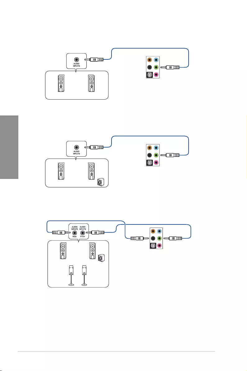
Connect to Stereo Speakers
Connect to 2-channel Speakers
Connect to 4-channel Speakers
TUF GAMING Z590-PLUS WIFI 2-21
Chapter 2
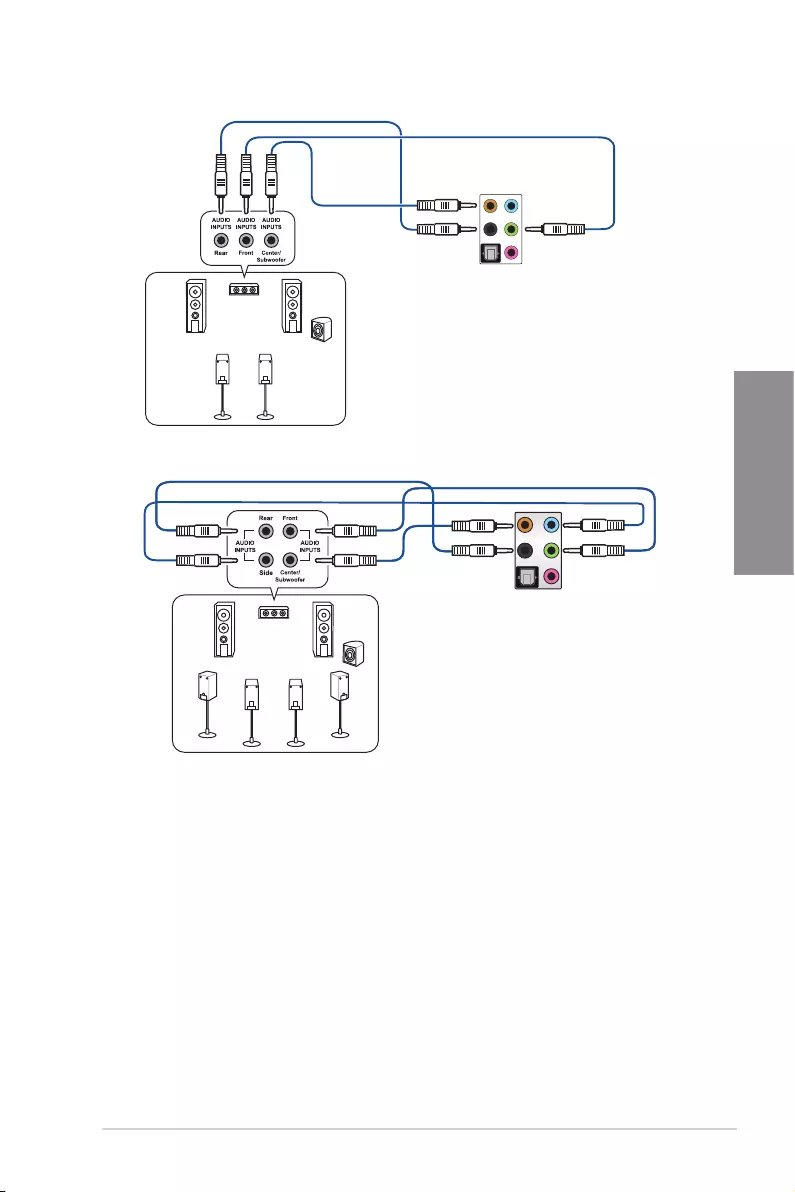
Connect to 5.1-channel Speakers
Connect to 7.1-channel Speakers
2-22 Chapter 2: Basic Installation
Chapter 2
2.3 Starting up for the first time
1. After making all the connections, replace the system case cover.
2. Ensure that all switches are off.
3. Connect the power cord to the power connector at the back of the system chassis.
4. Connect the power cord to a power outlet that is equipped with a surge protector.
5. Turn on the devices in the following order:
a. Monitor
b. External SCSI devices (starting with the last device on the chain)
c. System power
6. After applying power, the system power LED on the system front panel case lights
up. For systems with ATX power supplies, the system LED lights up when you press
the ATX power button. If your monitor complies with the “green” standards or if it has
a “power standby” feature, the monitor LED may light up or change from orange to
green after the system LED turns on.
The system then runs the power-on self tests (POST). While the tests are running,
the BIOS beeps (refer to the BIOS beep codes table) or additional messages appear
on the screen. If you do not see anything within 30 seconds from the time you turned
on the power, the system may have failed a power-on test. Check the jumper settings
and connections or call your retailer for assistance.
BIOS Beep Description
One short beep
VGA detected
Quick boot set to disabled
No keyboard detected
One continuous beep followed by two
short beeps then a pause (repeated) No memory detected
One continuous beep followed by three
short beeps No VGA detected
One continuous beep followed by four
short beeps Hardware component failure
7. At power on, hold down the <Delete> key to enter the BIOS Setup. Follow the
instructions in Chapter 3.
2.4 Turning off the computer
While the system is ON, press the power button for less than four seconds to put the system
on sleep mode or soft-off mode, depending on the BIOS setting. Press the power button
for more than four seconds to let the system enter the soft-off mode regardless of the BIOS
setting.
TUF GAMING Z590-PLUS WIFI 3-1
Chapter 3
For more details on BIOS and RAID configurations, please refer to www.asus.com/
support.
3.1 Knowing BIOS
The new ASUS UEFI BIOS is a Unified Extensible Interface that complies with UEFI
architecture, offering a user-friendly interface that goes beyond the traditional keyboard-
only BIOS controls to enable a more flexible and convenient mouse input. You can easily
navigate the new UEFI BIOS with the same smoothness as your operating system. The
term “BIOS” in this user manual refers to “UEFI BIOS” unless otherwise specified.
BIOS (Basic Input and Output System) stores system hardware settings such as storage
device configuration, overclocking settings, advanced power management, and boot
device configuration that are needed for system startup in the motherboard CMOS. In
normal circumstances, the default BIOS settings apply to most conditions to ensure
optimal performance. DO NOT change the default BIOS settings except in the following
circumstances:
• An error message appears on the screen during the system bootup and requests you
to run the BIOS Setup.
• You have installed a new system component that requires further BIOS settings or
update.
Inappropriate BIOS settings may result to instability or boot failure. We strongly
recommend that you change the BIOS settings only with the help of a trained
service personnel.
BIOS settings and options may vary due to different BIOS release versions. Please refer
to the latest BIOS version for settings and options.
3
BIOS and RAID Support
Chapter 3: BIOS and RAID Support
For more information on BIOS configurations, please refer to
https://www.asus.com/support, or download the BIOS manual
by scanning the QR code.

3-2 Chapter 3: BIOS Setup
Chapter 3
3.2 BIOS Setup program
Use the BIOS Setup to update the BIOS or configure its parameters. The BIOS screens
include navigation keys and brief onscreen help to guide you in using the BIOS Setup
program.
Entering BIOS at startup
To enter BIOS Setup at startup, press <Delete> or <F2> during the Power-On Self Test
(POST). If you do not press <Delete> or <F2>, POST continues with its routines.
Entering BIOS Setup after POST
To enter BIOS Setup after POST:
• Press <Ctrl>+<Alt>+<Delete> simultaneously.
• Press the reset button on the system chassis.
• Press the power button to turn the system off then back on. Do this option only if you
failed to enter BIOS Setup using the first two options.
After doing either of the three options, press <Delete> key to enter BIOS.
• Ensure that a USB mouse is connected to your motherboard if you want to use the
mouse to control the BIOS Setup program.
• If the system becomes unstable after changing any BIOS setting, load the default
settings to ensure system compatibility and stability. Select the Load Optimized
Defaults item under the Exit menu or press hotkey <F5>.
• If the system fails to boot after changing any BIOS setting, try to clear the CMOS and
reset the motherboard to the default value.
• The BIOS Setup program does not support Bluetooth devices.
BIOS menu screen
The BIOS Setup program can be used under two modes: EZ Mode and Advanced Mode.
You can change modes from Setup Mode in Boot menu or by pressing the <F7> hotkey.
3.3 EZ Update
The EZ Update is a utility that allows you to update the motherboard BIOS in Windows®
environment.
EZ Update requires an Internet connection either through a network or an ISP (Internet
Service Provider).

TUF GAMING Z590-PLUS WIFI 3-3
Chapter 3
3.4 ASUS EZ Flash 3
The ASUS EZ Flash 3 feature allows you to update the BIOS without using an OS-based
utility.
Ensure to load the BIOS default settings to ensure system compatibility and stability.
Select the Load Optimized Defaults item under the Exit menu or press hotkey <F5>.
To update the BIOS by USB:
• This function can support devices such as a USB flash disk with FAT 32/16 format
and single partition only.
• DO NOT shut down or reset the system while updating the BIOS to prevent system
boot failure!
1. Insert the USB flash disk that contains the latest BIOS file to the USB port.
2. Enter the Advanced Mode of the BIOS Setup program. Go to the Tool menu to select
ASUS EZ Flash 3 Utility and press <Enter>.
3. Press the Left/Right arrow keys to switch to the Drive field.
4. Press the Up/Down arrow keys to find the USB flash disk that contains the latest
BIOS, and then press <Enter>.
5. Press the Left/Right arrow keys to switch to the Folder field.
6. Press the Up/Down arrow keys to find the BIOS file, and then press <Enter> to
perform the BIOS update process. Reboot the system when the update process is
done.
3-4 Chapter 3: BIOS Setup
Chapter 3
3.5 ASUS CrashFree BIOS 3
The ASUS CrashFree BIOS 3 utility is an auto recovery tool that allows you to restore the
BIOS le when it fails or gets corrupted during the updating process. You can restore a
corrupted BIOS le using a USB ash drive that contains the BIOS le.
Recovering the BIOS
1. Download the latest BIOS version for this motherboard from
https://www.asus.com/support/.
2. Rename the BIOS file as ASUS.CAP or TGZ590PW.CAP and copy the renamed
BIOS file to a USB flash drive.
3. Turn on the system.
4. Insert the USB flash drive containing the BIOS file to a USB port.
5. The utility automatically checks the devices for the BIOS file. When found, the utility
reads the BIOS file and enters ASUS EZ Flash 3 automatically.
6. The system requires you to enter BIOS Setup to recover the BIOS setting. To ensure
system compatibility and stability, we recommend that you press <F5> to load default
BIOS values.
DO NOT shut down or reset the system while updating the BIOS! Doing so can cause
system boot failure!
TUF GAMING Z590-PLUS WIFI 3-5
Chapter 3
3.6 RAID configurations
The motherboard comes with the Intel® Rapid Storage Technology that supports RAID 0,
RAID 1, RAID 5 and RAID 10 configuration.
RAID definitions
RAID 0 (Data striping) optimizes two identical hard disk drives to read and write data in
parallel, interleaved stacks. Two hard disks perform the same work as a single drive but at a
sustained data transfer rate, double that of a single disk alone, thus improving data access
and storage. Use of two new identical hard disk drives is required for this setup.
RAID 1 (Data mirroring) copies and maintains an identical image of data from one drive to
a second drive. If one drive fails, the disk array management software directs all applications
to the surviving drive as it contains a complete copy of the data in the other drive. This RAID
configuration provides data protection and increases fault tolerance to the entire system.
Use two new drives or use an existing drive and a new drive for this setup. The new drive
must be of the same size or larger than the existing drive.
RAID 5 stripes both data and parity information across three or more hard disk drives.
Among the advantages of RAID 5 configuration include better HDD performance, fault
tolerance, and higher storage capacity. The RAID 5 configuration is best suited for
transaction processing, relational database applications, enterprise resource planning, and
other business systems. Use a minimum of three identical hard disk drives for this setup.
RAID 10 is data striping and data mirroring combined without parity (redundancy data)
having to be calculated and written. With the RAID 10 configuration you get all the benefits
of both RAID 0 and RAID 1 configurations. Use four new hard disk drives or use an existing
drive and three new drives for this setup.
For more information on configuring your RAID sets, please
refer to the RAID Configuration Guide which you can find at
https://www.asus.com/support, or by scanning the QR code.

3-6 Chapter 3: BIOS Setup
Chapter 3

TUF GAMING Z590-PLUS WIFI A-1
Appendix
Appendix
Appendix
Notices
FCC Compliance Information
Responsible Party: Asus Computer International
Address: 48720 Kato Rd., Fremont, CA 94538, USA
Phone / Fax No: (510)739-3777 / (510)608-4555
Identification of the assembled product: INTEL Wi-Fi 6 AX201
Identification of the modular components used in the assembly:
Model Name: Wi-Fi 6 AX201 FCC ID: PD99560NG
This device complies with part 15 of the FCC Rules. Operation is subject to the following
two conditions: (1) This device may not cause harmful interference, and (2) this device must
accept any interference received, including interference that may cause undesired operation.
This equipment has been tested and found to comply with the limits for a Class B digital
device, pursuant to part 15 of the FCC Rules. These limits are designed to provide
reasonable protection against harmful interference in a residential installation. This
equipment generates, uses and can radiate radio frequency energy and, if not installed
and used in accordance with the instructions, may cause harmful interference to radio
communications. However, there is no guarantee that interference will not occur in a
particular installation. If this equipment does cause harmful interference to radio or television
reception, which can be determined by turning the equipment off and on, the user is
encouraged to try to correct the interference by one or more of the following measures:
— Reorient or relocate the receiving antenna.
— Increase the separation between the equipment and receiver.
— Connect the equipment into an outlet on a circuit different from that to which the receiver
is connected.
— Consult the dealer or an experienced radio/TV technician for help.
RF exposure warning
This equipment must be installed and operated in accordance with provided instructions and
the antenna(s) used for this transmitter must be installed to provide a separation distance of
at least 20 cm from all persons and must not be co-located or operating in conjunction with
any other antenna or transmitter. End-users and installers must be provide with antenna
installation instructions and transmitter operating conditions for satisfying RF exposure
compliance.
HDMI Compliance Statement
The terms HDMI, HDMI High-Definition Multimedia Interface, and the HDMI Logo are
trademarks or registered trademarks of HDMI Licensing Administrator, Inc.
A-2 Appendix
Appendix
Compliance Statement of Innovation, Science and Economic
Development Canada (ISED)
This device complies with Innovation, Science and Economic Development Canada licence
exempt RSS standard(s). Operation is subject to the following two conditions: (1) this device
may not cause interference, and (2) this device must accept any interference, including
interference that may cause undesired operation of the device.
Operation in the band 5150–5250 MHz is only for indoor use to reduce the potential for
harmful interference to co-channel mobile satellite systems.
CAN ICES-003(B)/NMB-003(B)
Déclaration de conformité de Innovation, Sciences et
Développement économique Canada (ISED)
Le présent appareil est conforme aux CNR d’Innovation, Sciences et Développement
économique Canada applicables aux appareils radio exempts de licence. L’exploitation est
autorisée aux deux conditions suivantes : (1) l’appareil ne doit pas produire de brouillage,
et (2) l’utilisateur de l’appareil doit accepter tout brouillage radioélectrique subi, même si le
brouillage est susceptible d’en compromettre le fonctionnement.
La bande 5150–5250 MHz est réservée uniquement pour une utilisation à l’intérieur afin de
réduire les risques de brouillage préjudiciable aux systèmes de satellites mobiles utilisant
les mêmes canaux.
CAN ICES-003(B)/NMB-003(B)
VCCI: Japan Compliance Statement
Class B ITE
Japan JATE
本製品は電気通信事業者(移動通信会社、固定通信会社、インターネットプロバイダ等)の通信回
線(公衆無線LANを含む)に直接接続することができません。本製品をインターネットに接続する
場合は、必ずルーター等を経由して接続してください。
KC: Korea Warning Statement

TUF GAMING Z590-PLUS WIFI A-3
Appendix
Google™ License Terms
Copyright© 2021 Google Inc. All Rights Reserved.
Licensed under the Apache License, Version 2.0 (the “License”); you may not use this file
except in compliance with the License. You may obtain a copy of the License at:
http://www.apache.org/licenses/LICENSE-2.0
Unless required by applicable law or agreed to in writing, software distributed under the
License is distributed on an “AS IS” BASIS, WITHOUT WARRANTIES OR CONDITIONS
OF ANY KIND, either express or implied.
See the License for the specific language governing permissions and limitations under the
License.
NCC: Taiwan Wireless Statement
「取得審驗證明之低功率射頻器材,非經核准,公司、商號或使用者均不得擅自變更頻
率、加大功率或變更原設計之特性及功能。低功率射頻器材之使用不得影響飛航安全及
干擾合法通信;經發現有干擾現象時,應立即停用,並改善至無干擾時方得繼續使用。
前述合法通信,指依電信管理法規定作業之無線電通信。低功率射頻器材須忍受合法通
信或工業、科學及醫療用電波輻射性電機設備之干擾。」
* 應避免影響附近雷達系統之操作。
Japan RF Equipment Statement
屋外での使用について
本製品は、5GHz帯域での通信に対応しています。電波法の定めにより5.2GHz、5.3GHz帯域の電
波は屋外で使用が禁じられています。
法律および規制遵守
本製品は電波法及びこれに基づく命令の定めるところに従い使用してください。日本国外では、
その国の法律または規制により、本製品の使用ができないことがあります。このような国では、本
製品を運用した結果、罰せられることがありますが、当社は一切責任を負いかねますのでご了承
ください。
Précautions d’emploi de l’appareil :
a. Soyez particulièrement vigilant quant à votre sécurité lors de l’utilisation de cet
appareil dans certains lieux (les avions, les aéroports, les hôpitaux, les stations-
service et les garages professionnels).
b. Évitez d’utiliser cet appareil à proximité de dispositifs médicaux implantés. Si
vous portez un implant électronique (stimulateurs cardiaques, pompes à insuline,
neurostimulateurs…), veuillez impérativement respecter une distance minimale de 15
centimètres entre cet appareil et l’implant pour réduire les risques d’interférence.
c. Utilisez cet appareil dans de bonnes conditions de réception pour minimiser le niveau
de rayonnement. Ce n’est pas toujours le cas dans certaines zones ou situations,
notamment dans les parkings souterrains, dans les ascenseurs, en train ou en voiture
ou tout simplement dans un secteur mal couvert par le réseau.
d. Tenez cet appareil à distance du ventre des femmes enceintes et du bas-ventre des
adolescents.

A-4 Appendix
Appendix
Declaration of compliance for product environmental
regulation
ASUS follows the green design concept to design and manufacture our products, and
makes sure that each stage of the product life cycle of ASUS product is in line with global
environmental regulations. In addition, ASUS disclose the relevant information based on
regulation requirements.
Please refer to http://csr.asus.com/Compliance.htm for information disclosure based on
regulation requirements ASUS is complied with:
EU REACH and Article 33
Complying with the REACH (Registration, Evaluation, Authorisation, and Restriction of
Chemicals) regulatory framework, we published the chemical substances in our products at
ASUS REACH website at http://csr.asus.com/english/REACH.htm.
EU RoHS
This product complies with the EU RoHS Directive. For more details, see
http://csr.asus.com/english/article.aspx?id=35
India RoHS
This product complies with the “India E-Waste (Management) Rules, 2016” and prohibits
use of lead, mercury, hexavalent chromium, polybrominated biphenyls (PBBs) and
polybrominated diphenyl ethers (PBDEs) in concentrations exceeding 0.1% by weight in
homogenous materials and 0.01% by weight in homogenous materials for cadmium, except
for the exemptions listed in Schedule II of the Rule.
Vietnam RoHS
ASUS products sold in Vietnam, on or after September 23, 2011,meet the requirements of
the Vietnam Circular 30/2011/TT-BCT.
Các sản phẩm ASUS bán tại Việt Nam, vào ngày 23 tháng 9 năm2011 trở về sau, đều phải đáp ứng
các yêu cầu của Thông tư 30/2011/TT-BCT của Việt Nam.
Turkey RoHS
AEEE Yönetmeliğine Uygundur
ASUS Recycling/Takeback Services
ASUS recycling and takeback programs come from our commitment to the highest
standards for protecting our environment. We believe in providing solutions for you to
be able to responsibly recycle our products, batteries, other components as well as the
packaging materials. Please go to http://csr.asus.com/english/Takeback.htm for detailed
recycling information in different regions.
TUF GAMING Z590-PLUS WIFI A-5
Appendix
DO NOT throw the motherboard in municipal waste. This product has been designed to
enable proper reuse of parts and recycling. This symbol of the crossed out wheeled bin
indicates that the product (electrical and electronic equipment) should not be placed in
municipal waste. Check local regulations for disposal of electronic products.
DO NOT throw the mercury-containing button cell battery in municipal waste. This symbol
of the crossed out wheeled bin indicates that the battery should not be placed in municipal
waste.
Regional notice for California
WARNING
Cancer and Reproductive Harm —
www.P65Warnings.ca.gov

A-6 Appendix
Appendix
Forenklet EU-overensstemmelseserklæring
ASUSTeK Computer Inc. erklærer hermed at denne enhed er i
overensstemmelse med hovedkravene og øvrige relevante bestemmelser i
direktivet 2014/53/EU. Hele EU-overensstemmelseserklæringen kan findes
på https://www.asus.com/support/
Wi-Fi, der bruger 5150-5350 MHz skal begrænses til indendørs brug i lande,
der er anført i tabellen:
Vereenvoudigd EU-conformiteitsverklaring
ASUSTeK Computer Inc. verklaart hierbij dat dit apparaat voldoet aan de
essentiële vereisten en andere relevante bepalingen van Richtlijn 2014/53/
EU. De volledige tekst van de EU-conformiteitsverklaring is beschikbaar op
https://www.asus.com/support/
De WiFi op 5150-5350MHz zal beperkt zijn tot binnengebruik voor in de
tabel vermelde landen:
Lihtsustatud EÜ vastavusdeklaratsioon
Käesolevaga kinnitab ASUSTek Computer Inc, et seade vastab direktiivi
2014/53/EÜ olulistele nõuetele ja teistele asjakohastele sätetele. EL
vastavusdeklaratsiooni täistekst on saadaval veebisaidil
https://www.asus.com/support/
Sagedusvahemikus 5150-5350 MHz töötava WiFi kasutamine on järgmistes
riikides lubatud ainult siseruumides:
Eurooppa — EY:n vaatimustenmukaisuusvakuutus
ASUSTek Computer Inc. ilmoittaa täten, että tämä laite on direktiivin
2014/53/EU olennaisten vaatimusten ja muiden asiaankuuluvien lisäysten
mukainen. Koko EY:n vaatimustenmukaisuusvakuutuksen teksti on
luettavissa osoitteessa https://www.asus.com/support/
5 150 — 5 350 MHz:in taajuudella toimiva WiFi on rajoitettu sisäkäyttöön
taulukossa luetelluissa maissa:
ASUSTek Computer Inc
2014/53/EU
.https://www.asus.com/support/
WiFi 5150-5350
Απλοποιημένη Δήλωση Συμμόρφωσης ΕΕ
Διά του παρόντος η ASUSTek Computer Inc. δηλώνει ότι αυτή η συσκευή
είναι σύμμορφη με τις βασικές προϋποθέσεις και άλλες σχετικές διατάξεις
της Οδηγίας 2014/53/ΕE. Το πλήρες κείμενο της δήλωσης συμμόρφωσης της
ΕΕ είναι διαθέσιμο στη διεύθυνση https://www.asus.com/support/
Το WiFi που λειτουργεί στη ζώνη 5150-5350MHz περιορίζεται για χρήση σε
εσωτερικούς χώρους για τις χώρες που αναφέρονται στον παρακάτω πίνακα:
2014/53/EU
5150-5350MHzWi-Fi
Egyszerűsített EU megfelelőségi nyilatkozat
Az ASUSTek Computer Inc. ezennel kijelenti, hogy ez az eszköz megfelel az
2014/53/EU sz. irányelv alapvető követelményeinek és egyéb vonatkozó
rendelkezéseinek. Az EU megfelelőségi nyilatkozat teljes szövegét a
következő weboldalon tekintheti meg: https://www.asus.com/support/
Az 5150-5350 MHz-es sávban működő Wi-Fi-t beltéri használatra kell
korlátozni az alábbi táblázatban felsorolt országokban:
Pernyataan Kesesuaian UE yang Disederhanakan
ASUSTeK Computer Inc. dengan ini menyatakan bahwa perangkat ini
memenuhi persyaratan utama dan ketentuan relevan lainnya yang terdapat
pada Petunjuk 2014/53/EU. Teks lengkap pernyataan kesesuaian EU tersedia
di: https://www.asus.com/support/
WiFi yang Beroperasi pada 5150-5350 MHz akan terbatas untuk penggunaan
dalam ruangan di negara yang tercantum dalam tabel
Vienkāršota ES atbilstības paziņojums
ASUSTeK Computer Inc. ar šo paziņo, ka šī ierīce atbilst Direktīvas
2014/53/ES būtiskajām prasībām un citiem citiem saistošajiem
nosacījumiem. Pilns ES atbilstības paziņojuma teksts pieejams šeit:
https://www.asus.com/support/
Wi-Fi darbība 5150–5350MHz ir jāierobežo lietošanai telpās valstīs, kuras
norādītas tālāk.
Simplified EU Declaration of Conformity
ASUSTek Computer Inc. hereby declares that this device is in compliance
with the essential requirements and other relevant provisions of Directive
2014/53/EU. Full text of EU declaration of conformity is available at
https://www.asus.com/support/
The WiFi operating in the band 5150-5350MHz shall be restricted to indoor
use for countries listed in the table below:
Déclaration simplifiée de conformité de l’UE
ASUSTek Computer Inc. déclare par la présente que cet appareil est
conforme aux critères essentiels et autres clauses pertinentes de la directive
2014/53/EU. La déclaration de conformité de l’UE peut être téléchargée à
partir du site internet suivant : https://www.asus.com/support/
Dans la plage de fréquence 5150-5350 MHz, le Wi-Fi est restreint à une
utilisation en intérieur dans les pays listés dans le tableau ci-dessous:
Vereinfachte EU-Konformitätserklärung
ASUSTek COMPUTER INC erklärt hiermit, dass dieses Gerät mit den
grundlegenden Anforderungen und anderen relevanten Bestimmungen
der Richtlinie 2014/53/EU übereinstimmt. Der gesamte Text der EU-
Konformitätserklärung ist verfügbar unter: https://www.asus.com/support/
Der WLAN-Betrieb im Band von 5150-5350 MHz ist für die in der unteren
Tabelle aufgeführten Länder auf den Innenbereich beschränkt:
Dichiarazione di conformità UE semplificata
ASUSTek Computer Inc. con la presente dichiara che questo dispositivo è
conforme ai requisiti essenziali e alle altre disposizioni pertinenti con la
direttiva 2014/53/EU. Il testo completo della dichiarazione di conformità UE
è disponibile all’indirizzo: https://www.asus.com/support/
L’utilizzo della rete Wi-Fi con frequenza compresa nell’intervallo 5150-
5350MHz deve essere limitato all’interno degli edifici per i paesi presenti
nella seguente tabella:
Упрощенное заявление о соответствии европейской директиве
ASUSTek Computer Inc. заявляет, что устройство соответствует основным
требованиям и другим соответствующим условиям директивы 2014/53/
EU. Полный текст декларации соответствия ЕС доступен на
https://www.asus.com/support/
Работа WiFi в диапазоне частот 5150-5350 должна быть ограничена
использованием в помещениях для стран, перечисленных в таблице ниже:
ASUSTek Computer
2014/53/EU
https://www.asus.com/support/
5150-5350 WiFi
Опростена декларация за съответствие на ЕС
С настоящото ASUSTek Computer Inc. декларира, че това устройство е
в съответствие със съществените изисквания и другите приложими
постановления на свързаната Директива 2014/53/EC. Пълният текст на
ЕС декларация за съвместимост е достъпен на адрес
https://www.asus.com/support/
WiFi, работеща в диапазон 5150-5350MHz, трябва да се ограничи до
употреба на закрито за страните, посочени в таблицата по-долу:
Declaração de Conformidade UE Simplificada
ASUSTek Computer Inc. declara que este dispositivo está em conformidade
com os requisitos essenciais e outras disposições relevantes relacionadas às
diretivas 2014/53/UE. O texto completo da declaração de conformidade CE
está disponível em https://www.asus.com/support/
O WiFi operando na banda 5150-5350MHz deve ser restrito para uso interno
para os países listados na tabela abaixo:
Pojednostavljena EU Izjava o sukladnosti
ASUSTeK Computer Inc. ovim izjavljuje da je ovaj uređaj sukladan s bitnim
zahtjevima i ostalim odgovarajućim odredbama direktive 2014/53/EU. Cijeli
tekst EU izjave o sukladnosti dostupan je na https://www.asus.com/support/
WiFi koji radi na opsegu frekvencija 5150-5350 MHz bit će ograničen na
upotrebu u zatvorenom prostoru u zemljama na donjem popisu:
Zjednodušené prohlášení o shodě EU
Společnost ASUSTek Computer Inc. tímto prohlašuje, že toto zařízení splňuje
základní požadavky a další příslušná ustanovení směrnice 2014/53/ EU. Plné
znění prohlášení o shodě EU je k dispozici na adrese
https://www.asus.com/support/
V zemích uvedených v tabulce je provoz sítě Wi-Fi ve frekvenčním rozsahu 5
150 — 5 350 MHz povolen pouze ve vnitřních prostorech:
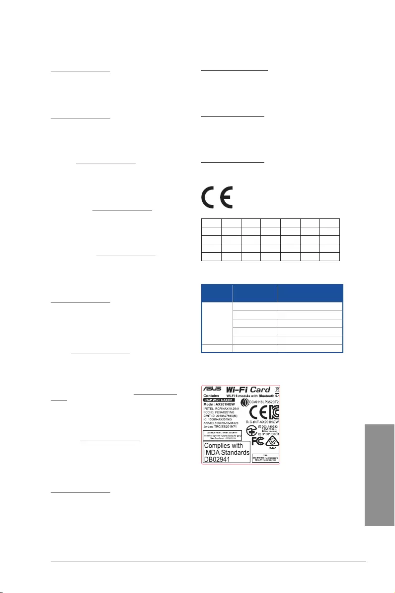
TUF GAMING Z590-PLUS WIFI A-7
Appendix
Supaprastinta ES atitikties deklaracija
Šiame dokumente bendrovė „ASUSTek Computer Inc.“ pareiškia, kad šis
prietaisas atitinka pagrindinius reikalavimus ir kitas susijusias Direktyvos
2014/53/ES nuostatas. Visas ES atitikties deklaracijos tekstas pateikiamas čia:
https://www.asus.com/support/
Toliau nurodytose šalyse „WiFi“ ryšiu, veikiančiu 5 150–5 350 MHz dažnio
juostoje, galima naudotis tik patalpose:
Forenklet EU-samsvarserklæring
ASUSTek Computer Inc. erklærer herved at denne enheten er i samsvar med
hovedsaklige krav og andre relevante forskrifter i direktivet 2014/53/EU.
Fullstendig tekst for EU-samsvarserklæringen finnes på:
https://www.asus.com/support/
Wi-Fi-området 5150–5350 MHz skal begrenses til innendørs bruk for landene
som er oppført i tabellen:
Uproszczona deklaracja zgodności UE
Firma ASUSTek Computer Inc. niniejszym oświadcza, że urządzenie to jest
zgodne z zasadniczymi wymogami i innymi właściwymi postanowieniami
dyrektywy 2014/53/EU. Pełny tekst deklaracji zgodności UE jest dostępny
pod adresem https://www.asus.com/support/
W krajach wymienionych w tabeli działanie sieci Wi-Fi w paśmie 5150–
5350MHz powinno być ograniczone wyłącznie do pomieszczeń:
Declaração de Conformidade Simplificada da UE
A ASUSTek Computer Inc. declara que este dispositivo está em
conformidade com os requisitos essenciais e outras disposições relevantes
da Diretiva 2014/53/UE. O texto integral da declaração de conformidade da
UE está disponível em https://www.asus.com/support/
A utilização das frequências WiFi de 5150 a 5350MHz está restrita a
ambientes interiores nos países apresentados na tabela:
Declarație de conformitate UE, versiune simplificată
Prin prezenta, ASUSTek Computer Inc. declară că acest dispozitiv este în
conformitate cu reglementările esențiale și cu celelalte prevederi relevante
ale Directivei 2014/53/UE. Textul complet al declarației de conformitate UE
este disponibil la adresa https://www.asus.com/support/
Pentru ţările listate în tabelul de mai jos, reţelele WiFi care funcţionează în
banda de frecvenţă de 5.150-5.350 MHz trebuie utilizate doar în interior:
Pojednostavljena Deklaracija o usaglašenosti EU
ASUSTek Computer Inc. ovim izjavljuje da je ovaj uređaj usaglašen sa
osnovnim zahtevima i drugim relevantnim odredbama Direktive 2014/53/
EU. Ceo tekst Deklaracije o usaglašenosti EU dostupan je na lokaciji
https://www.asus.com/support/
WiFi koji radi u frekventnom opsegu od 5150 MHz do 5350 MHz ograničen
je isključivo na upotrebu u zatvorenom prostoru za zemlje navedene u
tabeli ispod:
Zjednodušené vyhlásenie o zhode platné pre EÚ
Spoločnosť ASUSTek Computer Inc. týmto vyhlasuje, že toto zariadenie je
v súlade so základnými požiadavkami a ďalšími príslušnými ustanoveniami
smernice č. 2014/53/EÚ. Plné znenie vyhlásenia o zhode pre EÚ je k dispozícii
na lokalite https://www.asus.com/support/
Činnosť WiFi v pásme 5150 — 5350 MHz bude obmedzená na použitie vo
vnútornom prostredí pre krajiny uvedené v tabuľke nižšie:
Poenostavljena izjava EU o skladnosti
ASUSTek Computer Inc. tukaj izjavlja, da je ta naprava skladna s temeljnimi
zahtevami in drugimi relevantnimii določili Direktive 2014/53/EU. Polno
besedilo izjave EU o skladnosti je na voljo na https://www.asus.com/
support/
WiFi, ki deluje v pasovnem območju 5150–5350MHz, mora biti v državah,
navedenih v spodnjem seznamu, omejen na notranjo uporabo:
Declaración de conformidad simplificada para la UE
Por la presente, ASUSTek Computer Inc. declara que este dispositivo cumple
los requisitos básicos y otras disposiciones pertinentes de la directiva
2014/53/EU. En https://www.asus.com/support/ está disponible el texto
completo de la declaración de conformidad para la UE.
La conexión WiFi con una frecuencia de funcionamiento de 5150-5350 MHz
se restringirá al uso en interiores para los países enumerados en la tabla:
Förenklad EU-försäkran om överensstämmelse
ASUSTek Computer Inc. deklarerar härmed att denna enhet överensstämmer
med de grundläggande kraven och andra relevanta bestämmelser i direktiv
2014/53/EU. Fullständig text av EU-försäkran om överensstämmelse finns på
https://www.asus.com/support/
WiFi som använder 5150-5350 MHz kommer att begränsas för användning
inomhus i de länder som anges i tabellen:
ประกาศเกี่ยวกับความสอดคล้องของสหภาพยุโรปแบบย่อ
ASUSTek Computer Inc.
ขอประกาศในที่นี้ว่าอุปกรณ์นี้มีความสอดคล้องกับความ
ต้องการที่จำาเป็นและเงื่อนไขที่เกี่ยวข้องอื่น ๆ ของบทบัญญัติข้อกำาหนด
2014/53/EU เนื้อหาที่สมบูรณ์ของประกาศความสอดคล้องกับ EU มีอยู่ที่
https://www.asus.com/support/
การทำางานของ WiFi ที่ 5150-5350MHz
ถูกจำากัดให้ใช้ในอาคารสำาหรับประเทศที่แสดงในตาราง
Basitleştirilmiş AB Uyumluluk Bildirimi
ASUSTek Computer Inc., bu aygıtın 2014/53/EU Yönergesinin temel
gereksinimlerine ve diğer ilgili hükümlerine uygun olduğunu bildirir. AB
uygunluk bildiriminin tam metni şu adreste bulunabilir:
https://www.asus.com/support/
5150-5350 MHz arasındaki WiFi çalışması, tabloda listelenen ülkeler için
iç mekân kullanımıyla kısıtlanacaktır.
Спрощена декларація про відповідність нормам ЄС
ASUSTek Computer Inc. заявляє, що цей пристрій відповідає основним
вимогам та іншим відповідним вимогам Директиви 2014 / 53 / EU.
Повний текст декларації відповідності нормам ЄС доступний на
https://www.asus.com/support/
Робота Wi-Fi на частоті 5150-5350 МГц обмежується використанням у
приміщенні для країн, поданих у таблиці нижче:
AT BE BG CZ DK EE FR
DE IS IE IT EL ES CY
LV LI LT LU HU MT NL
NO PL PT RO SI SK TR
FI SE CH UK HR
Intel® Wi-Fi 6 AX201 output power table:
Function Frequency Maximum Output Power
(EIRP)
WIFI
2412 — 2472 MHz 17.19 dBm
5150 — 5250 MHz 20.31 dBm
5250 — 5350 MHz 20.23 dBm
5470 — 5725 MHz 20.32 dBm
5725 — 5850 MHz 11.58 dBm
Bluetooth 2402 — 2480 MHz 10.35 dBm
For the standard EN 300 440, if this device operates in 5725-5875 MHz,
it will be considered as a receiver category 2.
Contains

A-8 Appendix
Appendix
EN: ASUS Guarantee Information
• ASUS offers a voluntary manufacturer’s Commercial Guarantee.
• ASUS reserves the right to interpret the provisions of the ASUS
Commercial Guarantee.
• This ASUS Commercial Guarantee is provided independently and
in addition to the statutory Legal Guarantee and in no way affects
or limits the rights under the Legal Guarantee.
For all the guarantee information, please visit
https://www.asus.com/support.
CZ: Informace o záruce společnosti ASUS
• Společnost ASUS nabízí dobrovolnou komerční záruku výrobce.
• Společnost ASUS si vyhrazuje právo vykládat ustanovení
komerční záruky společnosti ASUS.
• Tato komerční záruka společnosti ASUS je poskytována nezávisle
a jako doplněk zákonné záruky a žádným způsobem neovlivňuje
ani neomezuje práva vyplývající ze zákonné záruky.
Všechny informace o záruce najdete na adrese
https://www.asus.com/cz/support/.
CR: Informacije o ASUS jamstvu
• ASUS dragovoljno nudi komercijalno proizvođačko jamstvo.
• ASUS zadržava prava na tumačenje odredbi ASUS komercijalnog
jamstva.
• Ovo ASUS komercijalno jamstvo daje se neovisno i kao dodatak
zakonskom jamstvu i ni na koji način ne ograničuje prava iz okvira
zakonskog jamstva.
Sve informacije o jamstvu potražite na
https://www.asus.com/support.
DU: ASUS-garantie-informatie
• SUS biedt een vrijwillige commerciële garantie van de fabrikant.
• ASUS behoudt zich het recht voor om de bepalingen van de
commerciële garantie van ASUS uit te leggen.
• Deze commerciële garantie van ASUS wordt onafhankelijk en
als aanvulling op de statutaire Wettelijke garantie geboden en
beïnvloedt of beperkt in geen geval de rechten onder de wettelijke
garantie.
Voor alle informatie over de garantie, gaat u naar
https://www.asus.com/nl/support/.
I: Informativa sulla Garanzia ASUS
• ASUS offre una Garanzia Commerciale volontaria del produttore.
• ASUS si riserva il diritto di interpretare le disposizioni della
Garanzia Commerciale ASUS.
• La presente Garanzia Commerciale ASUS viene fornita in modo
indipendente e in aggiunta alla Garanzia Legale prevista per
legge e non pregiudica o limita in alcun modo i diritti previsti dalla
Garanzia Legale.
Per tutte le informazioni sulla garanzia, visitare
https://www.asus.com/it/support.
EE: Teave ASUS-e garantii kohta
• ASUS pakub vabatahtlikku tasulist tootjagarantiid.
• ASUS jätab endale õiguse tõlgendada ASUS-e tasulise garantii
tingimusi.
• See ASUS-e tasuline garantii on sõltumatu lisagarantii seadusega
kehtestatud garantiile ega mõjuta mingil määral seadusega
kehtestatud garantiid ning seadusega kehtestatud garantii
piiranguid.
Vaadake garantiiga seotud teavet veebisaidilt
https://www.asus.com/ee/.
GK: Πληροφορίες εγγύησης ASUS
• Η ASUS προσφέρει μια εθελοντική Εμπορική εγγύηση κατασκευαστή.
• Η ASUS διατηρεί το δικαίωμα ερμηνείας των διατάξεων της Εμπορικής
εγγύησης ASUS.
• Αυτή η Εμπορική εγγύηση ASUS παρέχεται ανεξάρτητα και
επιπροσθέτως της θεσμικής Νομικής εγγύησης και σε καμία περίπτωση
δεν επηρεάζει ή περιορίζει τα δικαιώματα βάσει της Νομικής εγγύησης.
Για όλες τις πληροφορίες εγγύησης, επισκεφθείτε τη διεύθυνση
https://www.asus.com/gr-el/.
DA: ASUS garantioplysninger
• ASUS tilbyder en valgfri handelsmæssig garanti.
• ASUS forbeholder sig retten til at fortolke bestemmelserne i ASUS’
handelsmæssige garanti.
• Denne handelsmæssige garanti fra ASUS tilbydes uafhængigt,
som en tilføjelse til den lovbestemte juridiske garanti og den
påvirker eller begrænser på ingen måde rettighederne i den
juridiske garanti.
Alle garantioplysningerne kan findes på
https://www.asus.com/dk/support/.
HUG: ASUS garanciális információk
• Az ASUS önkéntes gyártói kereskedelmi garanciát kínál.
• Az ASUS fenntartja magának a jogot, hogy értelmezze az ASUS
kereskedelmi garanciára vonatkozó rendelkezéseket.
• Ezt a kereskedelmi garanciát az ASUS függetlenül és a törvényes
garancia mellett nyújtja és semmilyen módon nem befolyásolja,
vagy korlátozza a jogi garancia nyújtotta jogokat.
A garanciára vonatkozó teljes körű információkért látogasson el a
https://www.asus.com/hu/support/ oldalra.
BG: Информация за гаранцията от ASUS
• ASUS предлага доброволна търговска гаранция от производителя.
• ASUS си запазва правото да тълкува условията на търговската
гаранция на ASUS.
• Тази търговска гаранция на ASUS се предлага независимо от
и в допълнение на законовата гаранция. Тя по никакъв начин
не оказва влияние върху правата на потребителя в законовата
гаранция и по никакъв начин не ги ограничава.
За цялостна информация относно гаранцията, моля, посетете
https://www.asus.com/support.
LV: ASUS garantijas informācija
• ASUS piedāvā brīvprātīgu ražotāja komerciālo garantiju.
• ASUS patur tiesības interpretēt ASUS komerciālās garantijas
noteikumus.
• Šī ASUS komerciālā garantija tiek piedāvāta neatkarīgi un
papildus likumā noteiktajai juridiskajai garantijai, un tā nekādi
neietekmē vai neierobežo juridiskajā garantijā noteiktās tiesības.
Lai iegūtu informāciju par garantiju, apmeklējiet vietni
https://www.asus.com/lv/.
F: Garantie ASUS
• ASUS fournit une garantie commerciale en tant que garantie
volontaire du fabricant.
• ASUS se réserve le droit d’interpréter et de clarifier les
informations relatives à la garantie commerciale ASUS.
• Cette garantie commerciale ASUS est fournie indépendamment
et parallèlement à la garantie légale, elle n’affecte ou ne limite
d’aucune façon les droits acquis par la garantie légale.
Pour plus d’informations sur la garantie, consultez le site
https://www.asus.com/fr/support/.
G: ASUS Garantieinformationen
• ASUS bietet eine freiwillige Warengarantie des Herstellers an.
• ASUS behält sich das Recht zur Auslegung der Bestimmungen in
der ASUS Warengarantie vor.
• Diese ASUS Warengarantie wird unabhängig und zusätzlich zur
rechtmäßigen gesetzlichen Garantie gewährt und beeinträchtigt
oder beschränkt in keiner Weise die Rechte aus der gesetzlichen
Garantie.
Die vollständigen Garantieinformationen finden Sie unter
https://www.asus.com/de/support/.
R: Информация о гарантии ASUS
• ASUS предлагает добровольную гарантию от производителя.
• ASUS оставляет за собой право интерпретирование положений
гарантии ASUS.
• Настоящая гарантия ASUS никоим образом не ограничивает Ваши
права, предусмотренные локальным законодательством.
Для получения полной информации о гарантии посетите
https://www.asus.com/ru/support/.
Warranty
LT: Informacija apie ASUS garantiją
• ASUS siūlo savanorišką komercinę gamintojo garantiją.
• ASUS pasilieka teisę savo nuožiūra aiškinti šios komercinės ASUS
garantijos nuostatas.
• Ši komercinė ASUS garantija suteikiama nepriklausoma, be
įstatyminės teisinės garantijos, ir jokiu būdu nepaveikia ar
neapriboja teisinės garantijos suteikiamų teisių.
Norėdami gauti visą informaciją apie garantiją, apsilankykite
https://www.asus.com/lt/.
PL: Informacje o gwarancji firmy ASUS
• Firma ASUS oferuje dobrowolną gwarancję handlową producenta.
• Firma ASUS zastrzega sobie prawo do interpretacji warunków
gwarancji handlowej firmy ASUS.
• Niniejsza gwarancja handlowa firmy ASUS jest udzielana
niezależnie, jako dodatek do wymaganej ustawowo gwarancji
prawnej i w żaden sposób nie wpływa na prawa przysługujące na
mocy gwarancji prawnej ani ich nie ogranicza.
Wszelkie informacje na temat gwarancji można znaleźć na stronie
https://www.asus.com/pl/support.
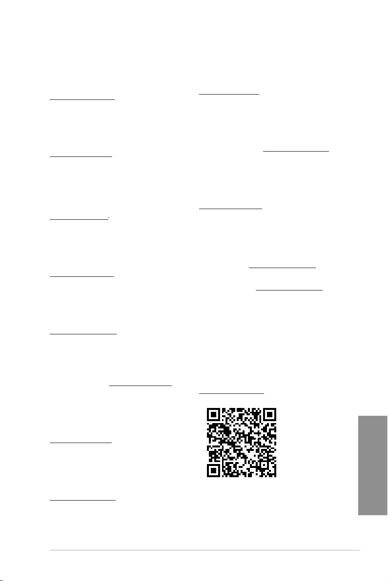
TUF GAMING Z590-PLUS WIFI A-9
Appendix
TR: ASUS Garanti Bilgileri
• ASUS, gönüllü olarak üretici Ticari Garantisi sunar.
• ASUS, ASUS Ticari Garantisinin hükümlerini yorumlama hakkını
saklı tutar.
• Bu ASUS Ticari Garantisi, bağımsız olarak ve hukuki Yasal
Garanti’ye ek olarak sağlanır ve hiçbir şekilde Yasal Garanti
kapsamındaki hakları etkilemez veya sınırlandırmaz.
Tüm garanti bilgileri için lütfen https://www.asus.com/tr/support adresini
ziyaret edin.
MX: Garantía y Soporte
Esta Garantía aplica en el país de compra. Usted acepta que en esta
garantía:
• Los procedimientos de servicio pueden variar en función del país.
• Algunos servicios y/o piezas de reemplazo pudieran no estar
disponibles en todos los países.
• Algunos países pueden tener tarifas y restricciones que se
apliquen en el momento de realizar el servicio, visite el sitio de
soporte de ASUS en https://www.asus.com/mx/support/ para ver
más detalles.
• Si tiene alguna queja o necesidad de un centro de reparación local
o el periodo de garantía del producto ASUS, por favor visite el sitio
de Soporte de ASUS en https://www.asus.com/mx/support/ para
mayores detalles.
Información de contacto ASUS
Esta garantía está respaldada por:
ASUSTeK Computer Inc.
Centro de Atención ASUS +52 (55) 1946-3663
SL: Informacije o garanciji ASUS
• ASUS ponuja prostovoljno tržno garancijo proizvajalca.
• ASUS si pridržuje pravico do razlage določb tržne garancije
družbe ASUS.
• Ta tržna garancija družbe ASUS je na voljo neodvisno in kot
dodatek zakonsko predpisani pravni garanciji ter na noben način
ne vpliva na pravice, ki jih zagotavlja pravna garancija, oziroma jih
omejuje.
Vse informacije o garanciji najdete na spletnem mestu
https://www.asus.com/support.
SK: Informácie o záruke ASUS
• ASUS ponúka dobrovoľnú obchodnú záruku výrobcu.
• ASUS si vyhradzuje právo interpretovať ustanovenia obchodnej
záruky ASUS.
• Táto obchodná záruka ASUS je poskytnutá nezávisle a navyše
k zákonnej záruke a v žiadnom prípade neovplyvňuje ani
neobmedzuje tieto práva podľa tejto zákonnej záruky.
Všetky ďalšie informácie o záruke nájdete na
https://www.asus.com/sk/support.
ES: Información de garantía de ASUS
• ASUS ofrece una garantía comercial voluntaria del fabricante.
• ASUS se reserva el derecho de interpretar las disposiciones de
esta garantía comercial de ASUS.
• Esta garantía comercial de ASUS se proporciona de forma
independiente y adicional a la garantía estatutaria y de ninguna
manera afecta a los derechos bajo la garantía legal ni los limita.
Para obtener toda la información sobre la garantía, visite
https://www.asus.com/ES/support/.
FI: ASUS-takuutiedot
• ASUS tarjoaa vapaaehtoisen valmistajan kaupallisen takuun.
• ASUS pidättää oikeuden tulkita ASUS-kaupallisen takuun ehdot.
• Tämä ASUS-kaupallinen takuu tarjotaan itsenäisesti lakisääteisen
oikeudellisen takuun lisäksi eikä se vaikuta millään tavoin laillisen
takuun oikeuksiin tai rajoita niitä.
Saadaksesi kaikki takuutiedot, siirry osoitteeseen
https://www.asus.com/fi/support.
NW: Informasjon om ASUS-garanti
• ASUS tilbyr som produsent en frivillig kommersiell garanti.
• ASUS forbeholder seg retten til å tolke bestemmelsene i ASUS sin
kommersielle garanti.
• ASUS sin kommersielle garanti gis uavhengig og i tillegg til den
lovbestemte juridiske garantien, og verken påvirker eller begrenser
rettighetene under den juridiske garantien på noen måte.
Du finner fullstendig informasjon om garanti på
https://www.asus.com/no/support/.
SB: Informacije o ASUS garanciji
• ASUS nudi dobrovoljnu proizvođačku komercijalnu garanciju.
• ASUS zadržava pravo da tumači odredbe svoje ASUS
komercijalne garancije.
• Ova ASUS komercijalna garancija daje se nezavisno, kao dodatak
zakonskoj pravnoj garanciji, i ni ka koji način ne utiče na i ne
ograničava prava data pravnom garancijom.
Za sve informacije o garanciji, posetite
https://www.asus.com/support/.
SW: ASUS garantiinformation
• ASUS erbjuder en frivillig kommersiell tillverkningsgaranti.
• ASUS förbehåller sig rätten att tolka bestämmelserna i ASUS
kommersiella garanti.
• Denna kommersiella garanti från ASUS tillhandahålles separat
och som tillägg till den lagstadgade garantin, och påverkar eller
begränsar på intet sätts rättigheterna under den lagstadgade
garantin.
För all garantiinformation, besök https://www.asus.com/se/support/.
UA: Інформація про Гарантію ASUS
• ASUS пропонує добровільну Комерційну Гарантію виробника.
• ASUS застерігає за собою право тлумачити положення Комерційної
Гарантії ASUS
• Цю Комерційну Гарантію надано незалежно і на додаток до
обов’язкової Законної Гарантії; вона жодним чином не впливає на
права за Законною Гарантією і не обмежує їх.
Всю інформацію про гарантію подано тут:
https://www.asus.com/ua/support.
BP: Informações de garantia ASUS
Esta garantia aplica-se ao período definido pela garantia legal (90
dias) mais o período de garantia comercial oferecido pela ASUS.
Por exemplo: 12M significa 12 meses de garantia no total (3 meses
de garantia legal mais 9 meses de garantia contratual), 24 meses
significa 24 meses de garantia no total (3 meses de garantia legal
mais 21 meses de garantia contratual) e 36 meses significa 36 meses
de garantia no total (3 meses de garantia legal e 33 de garantia
contratual) a contar da data da garantia declarada (Data de Início
da Garantia).
Para todas as informações de garantia, visite
https://www.asus.com/br/support/.
PG: Informações de Garantia ASUS
• A ASUS oferece uma Garantia Comercial voluntária do fabricante.
• A ASUS reserva o direito de interpretar as disposições da
Garantia Comercial da ASUS.
• Esta Garantia Comercial da ASUS é fornecida de forma
independente além da Garantia Legal estatutária e não afeta nem
limita de qualquer forma os direitos estabelecidos na Garantia
Legal.
Para consultar todas as informações sobre a garantia, visite
https://www.asus.com/pt/support/.
RO: Informații despre garanția ASUS
• ASUS oferă o garanție comercială voluntară a producătorului.
• ASUS își rezervă dreptul de a interpreta prevederile garanției
comerciale ASUS.
• Această garanție comercială ASUS este oferită independent și în plus
față de garanția obligatorie legal și nu afectează sau limitează în niciun
fel drepturile acordate conform garanției legale.
Pentru toate informațiile legate de garanție, vizitați
https://www.asus.com/ro/support.

A-10 Appendix
Appendix
ASUS contact information
ASUSTeK COMPUTER INC.
Address 1F., No. 15, Lide Rd., Beitou Dist., Taipei City 112, Taiwan
Telephone +886-2-2894-3447
Fax +886-2-2890-7798
Web site https://www.asus.com
Technical Support
Telephone +86-21-38429911
Online support https://qr.asus.com/techserv
ASUS COMPUTER INTERNATIONAL (America)
Address 48720 Kato Rd., Fremont, CA 94538, USA
Telephone +1-510-739-3777
Fax +1-510-608-4555
Web site https://www.asus.com/us/
Technical Support
Support fax +1-812-284-0883
Telephone +1-812-282-2787
Online support https://qr.asus.com/techserv
ASUS COMPUTER GmbH (Germany and Austria)
Address Harkortstrasse 21-23, 40880 Ratingen, Germany
Web site https://www.asus.com/de
Online contact https://www.asus.com/support/Product/ContactUs/
Services/questionform/?lang=de-de
Technical Support
Telephone (DE) +49-2102-5789557
Telephone (AT) +43-1360-2775461
Online support https://www.asus.com/de/support
-
-
Инструкции по эксплуатации
-
Материнские платы
-
ASUS
-
TUF Gaming Z590-PLUS WIFI
-
Инструкция по эксплуатации
| Языки: |
Французский |
|---|---|
| Страницы: | 69 |
| Описание: | TUF GAMING Z590-PLUS WIFI User’s Manual ( French Edition ) |
Стр.
из
результат(ов) по запросу ««
×
|
|
NoDevice
Loading…
-
« Назад
Ctrl + ←
-
Вперёд »
Ctrl + →
Мануал подходит для устройств
-
ASUS TUF Gaming Z590-PLUS WIFI
ATX, сокет Intel LGA1200, чипсет Intel Z590, память 4xDDR4 до 5133 МГц, слоты: 2xPCIe x16 4.0 и 3.0, 2xPCIe x1, 3xM.2
Нет в наличии и под заказ
-
Следить за суперценой и добавить в избранное
График цен
от
207,47 р.
–24%
Суперцена
Мы каждый день анализируем цены и помечаем все выгодные предложения за
последние 60 дней
Характеристики
|
Общая информация |
|
| Дата выхода на рынок | 2021 г. |
|
Технические характеристики |
|
| Поддержка процессоров | Intel |
| Встроенный процессор | |
| Сокет | LGA1200 |
| Чипсет | Intel Z590 |
| Форм-фактор | ATX |
| Подсветка | |
|
Память |
|
| Тип памяти | DDR4 |
| Количество слотов памяти | 4 |
| Максимальный объём памяти | 128GB |
| Режим памяти | двухканальный |
| Максимальная частота памяти | 5 133 МГц (ОС) |
| Дополнительные характеристики ОЗУ | |
|
Слоты расширения |
|
| Версия PCI Express | 4.0 и 3.0 |
| Всего PCI Express x16 | 2 |
| Всего PCI Express x1 | 2 |
| Всего PCI Express x4 | |
| Всего PCI Express x8 | |
| Дополнительные характеристики PCI | 1 x PCIe 4.0/3.0 x16 + 1 x PCIe 3.0 x16 (max. x4)
Intel 11th & 10th Gen Processors Intel Z590 Chipset |
|
Интерфейсы накопителей |
|
| M.2 | 3 |
| Спецификации накопителей | Intel 11th Gen процессоры M.2_1 слот (Key M), type 2242/2260/2280/22110 только Intel 11th процессоры поддерживают PCIe 4.0 x4 режим, слот недоступен для остальных поколений процессоров Intel Z590 чипсет |
| SATA 3.0 | 6 |
| SATA 2.0 | |
| RAID | 0,1,5,10 |
| mSATA | |
| SAS | |
|
Сеть и связь |
|
| Слот для модуля Wi-Fi | |
| Wi-Fi | |
| Bluetooth | |
| Ethernet | 1x 2.5 Гбит/с (Intel I225-V) |
|
Аудио и Видео |
|
| Поддержка встроенной графики | |
| Поддержка SLi/CrossFire | CrossFireX |
| Встроенный звук | Realtek ALC S1200A |
| Звуковая схема | 7.1 |
|
Разъемы на задней панели |
|
| USB 2.0 | 2 |
| USB 3.2 Gen1 Type-A (5 Гбит/с) | 2 |
| USB 3.2 Gen2 Type-A (10 Гбит/с) | 2 |
| USB 3.2 Gen1 Type-C (5 Гбит/с) | |
| USB 3.2 Gen2 Type-C (10 Гбит/с) | |
| USB 3.2 Gen 2×2 (20 Гбит/с) | 1 |
| USB-C (Thunderbolt 3) | |
| USB-C (Thunderbolt 4) | |
| Цифровой выход S/PDIF | 1 |
| Аудио (3.5 мм jack) | 5 |
| COM | |
| LPT | |
| PS/2 | 1 |
| DisplayPort | 1 (1.4) |
| mini DisplayPort | |
| VGA (D-Sub) | |
| DVI | |
| HDMI | 1 |
|
Внутренние разъемы |
|
| USB 2.0 | 2 (4 порта) |
| USB 3.2 Gen1 Type-A (5 Гбит/с) | 1 (2 порта) |
| USB 3.2 Gen2 Type-A (10 Гбит/с) | |
| USB 3.2 Gen1 Type-C (5 Гбит/с) | 1 |
| USB 3.2 Gen2 Type-C (10 Гбит/с) | |
| USB 3.2 Gen 2×2 (20 Гбит/с) | |
| Thunderbolt 3 | 1 |
| Thunderbolt 4 | |
| Цифровой выход S/PDIF | |
| COM | 1 |
| LPT | |
| Разъемы для вентилятора ЦП | 2 |
| Разъемы для СЖО | 1 |
| Разъемы для корпусных вентиляторов | 3 |
| Разъемы для подсветки ARGB 5В | 2 |
| Разъемы для подсветки RGB 12В | 2 |
|
Габариты |
|
| Длина | 305 мм |
| Ширина | 244 мм |
Заметили неточность в описании?
Вышеприведенная информация получена из открытых источников,
в том числе с официальных сайтов и из каталогов
производителей.
При получении заказа ОБЯЗАТЕЛЬНО обращайте внимание на важные для
вас параметры и характеристики приобретаемого товара.
В случае выявления несовпадений в описании товара
вы можете обратиться за консультацией и помощью
в нашу
службу поддержки.
Все опубликованные в данном каталоге материалы являются
собственностью ООО «Онлайнер», любая публикация или копирование
(полное или частичное) без предварительного согласия запрещены.
Обратите внимание:
Может понадобится обновление BIOS для обеспечения работоспособности вашего процессора.
Описание, наименование и товарный знак сформированы
в информационных целях на основе данных из открытых источников:
с официального интернет-магазина за рубежом.
Условие по вознаграждению агента см в п. 2.3.4. Агентского договора
Таможенная пошлина
Таможенная пошлина и сборы
0₽
- Описание
-
Отзывы
-
Оплата
-
Доставка
Игровая материнская плата с чипсетом Intel Z590: процессорный разъем LGA 1200, форм-фактор ATX, 16 силовых модулей DrMOS, PCIe 4.0, три слота M.2, 2.5G Ethernet (контроллер Intel), HDMI, DisplayPort, USB 3.2 Gen2х2 Type-C, SATA 6 Гбит/с, фронтальный порт USB 3.2 Gen1 Type-C, поддержка Thunderbolt 4, синхронизируемая подсветка Aura.
Характеристики
Процессор
Процессорный разъём
LGA1200
Производитель поддерживаемых процессоров
Intel
Поддерживаемые процессоры
Core i9 / Core i7 / Core i5 / Core i3 / Pentium / Celeron
Чипсет
Производитель чипсета
Intel
Оперативная память
Поддерживаемая память
DDR4
Количество слотов под память
4
Количество каналов памяти
2
Частота работы памяти, МГц
5133(OC)/5000(OC)/4800(OC)/4700(OC)/4600(OC)/4500(OC)/4400(OC) /4266(OC)/4133(OC)/4000(OC)/3866(OC)/3733(OC)/3600(OC)/3466(OC)/3400(OC)/3333(OC)/3200/3000/2933/2800/2666/2400/2133
Поддержка профилей памяти
XMP
Максимальный объём памяти, ГБ
128
Слоты расширения
Режим работы слотов PCI-E x16
x16 + x4
Версия шины для слотов PCI-E x16
4.0 (x16) + 3.0 (x4)
Накопители
Разъёмы M.2 M Key для SSD дисков
3
Параметры разъёмов M.2
1x M Key Type 2242/2260/2280/22110 PCI-Е 4.0 x4, 1x M Key Type 2242/2260/2280 SATA & PCI-Е 3.0 x4, 1x M Key Type 2242/2260/2280/22110 SATA & PCI-Е 3.0 x4
Интерфейсы
Портов USB 2.0 на задней панели
2
Порты USB 3.0 (3.1 Gen 1)
5
Портов USB 3.0 (3.1 Gen 1) Type A на задней панели
2
Портов USB 3.0 (3.1 Gen 1) Type C на задней панели
—
Портов USB 3.1 (Gen 2) Type A на задней панели
2
Портов USB 3.1 (Gen 2) Type C на задней панели
1
Портов COM на задней панели
—
Сеть
Сетевой контроллер
Intel I225-V
Звук
Звуковой контроллер
Realtek ALC S1200A
Количество каналов звука
8
S/PDIF оптический выход
есть
Видео
Типоразмер
Коннектор питания, pin
24+8+4
Конструкция
Пассивное охлаждение
есть
Дополнительно
Поддержка Intel Optane
есть
Система подсветки
Aura Sync RGB
Отзывов пока нет — станьте первым, кто расскажет о товаре!
У нас можно оплатить заказ банковской картой.
Доставка товаров осуществляется курьером или на пункт выдачи заказов.
Удобный способ доставки можно выбрать при оформлении заказа.
Срок доставки может увеличиваться в зависимости от особенностей международных перевозок и региона доставки.
Условия об ориентировочных сроках доставки указаны в правилах пользования и условиях агентского договора.
| Общее количество интерфейсов USB
Общее количество интерфейсов USB USB (Universal Serial Bus — универсальная последовательная шина) — самый распространенный на сегодня интерфейс передачи данных для периферийных устройств, таких как мышки, клавиатуры, принтеры и многое другое. X |
14 |
| Количество интерфейсов USB на задней панели
Количество интерфейсов USB на задней панели USB (Universal Serial Bus — универсальная последовательная шина) — самый распространенный на сегодня интерфейс передачи данных для периферийных устройств, таких как мышки, клавиатуры, принтеры и многое другое. X |
7 |
| Общее количество интерфейсов USB 3.0
Общее количество интерфейсов USB 3.0 USB 3.0 — интерфейс, обеспечивающий теоретическую передачу данных до 5 Гбит/с. Следует отметить, что на практике очень редко получается найти устройства с такой фактической пропускной способностью. Является развитием стандарта USB 2.0 и полностью совместим с предыдущими версиями USB (1.0, 1.1. 2.0). X |
0 |
| Количество интерфейсов USB 3.0 на задней панели
Количество интерфейсов USB 3.0 на задней панели USB 3.0 — интерфейс, обеспечивающий теоретическую передачу данных до 5 Гбит/с. Следует отметить, что на практике очень редко получается найти устройства с такой фактической пропускной способностью. Является развитием стандарта USB 2.0 и полностью совместим с предыдущими версиями USB (1.0, 1.1. 2.0). X |
5 |
| Общее количество интерфейсов FireWire (IEEE1394a)
Общее количество интерфейсов FireWire (IEEE1394a) Firewire — интерфейс, предназначенный для обмена информацией между компьютером и различными электронными устройствами. X |
0 |
| Количество интерфейсов FireWire (IEEE1394a) на задней панели
Количество интерфейсов FireWire (IEEE1394a) на задней панели Firewire — интерфейс, предназначенный для обмена информацией между компьютером и различными электронными устройствами. X |
0 |
| Общее количество интерфейсов FireWire (IEEE1394b)
Общее количество интерфейсов FireWire (IEEE1394b) Firewire — интерфейс, предназначенный для обмена информацией между компьютером и различными электронными устройствами. X |
0 |
| Количество интерфейсов FireWire (IEEE1394b) на задней панели
Количество интерфейсов FireWire (IEEE1394b) на задней панели Firewire — интерфейс, предназначенный для обмена информацией между компьютером и различными электронными устройствами. X |
0 |
| Количество разъемов Thunderbolt на задней панели
Количество разъемов Thunderbolt на задней панели Thunderbolt — интерфейс, предназначенный для подключения периферийных устройств к компьютеру. Скорость передачи данных до 20 Гбит/с. X |
0 |
| Выход S/PDIF
Выход S/PDIF S/PDIF (Sony/Philips Digital Interface) — интерфейс, предназначенный для передачи аудиосигнала без преобразования в аналоговый сигнал, что позволяет избежать потерь в качестве. Используется для подключения акустических систем. X |
есть |
| Общее количество COM-портов
Общее количество COM-портов COM-порт (serial port — последовательный порт, COM-порт от англ. communications port) – порт, используемый для подключения к компьютеру мобильных телефонов и других периферийных устройств. В настоящее время используется очень редко из-за низкой скорости передачи данных. X |
0 |
| Количество COM-портов на задней панели
Количество COM-портов на задней панели COM-порт (serial port — последовательный порт, COM-порт от англ. communications port) – порт, используемый для подключения к компьютеру мобильных телефонов и других периферийных устройств. В настоящее время используется очень редко из-за низкой скорости передачи данных. X |
0 |
| Интерфейс GAME/MIDI
Интерфейс GAME/MIDI GAME/MIDI (Musical Instrument Digital Interface — цифровой интерфейс музыкальных инструментов) — интерфейс для подключения игровых манипуляторов, а также устройства с MIDI-интерфейсом, (синтезаторы). X |
нет |
| Интерфейс LPT
Интерфейс LPT LPT (Line Print Terminal) — параллельный интерфейс, предназначенный для подключения периферийных устройств к компьютеру. В основном, используется для подключения принтеров и других внешних устройств. Также может применяться для организации сети между компьютерами, программирования микроконтроллеров и пр.. X |
нет |
| Интерфейс LPT на задней панели
Интерфейс LPT на задней панели LPT (Line Print Terminal) — параллельный интерфейс, предназначенный для подключения периферийных устройств к компьютеру. В основном, используется для подключения принтеров и других внешних устройств. Также может применяться для организации сети между компьютерами, программирования микроконтроллеров и пр.. X |
нет |
| Компонентный видеовыход на задней панели
Компонентный видеовыход на задней панели Компонентный видеовыход используется для передачи аналогового видеосигнала. Интерфейс обычно выглядит как 3 порта RCA («тюльпан»). Позволяет обмениваться информацией со старыми видеоустройствами. X |
нет |
| Интерфейс D-Sub (VGA) на задней панели
Интерфейс D-Sub (VGA) на задней панели D-Sub (VGA) используется для передачи аналогового видеосигнала на монитор. При передаче данных возможно наличие шумов на видео. На данный момент устарел, используется для совместимости со старыми устройствами вывода видеоинформации (мониторы, проекторы и пр.). X |
нет |
| Интерфейс DVI на задней панели
Интерфейс DVI на задней панели DVI (Digital Visual Interface – цифровой видео интерфейс) используется для передачи цифрового видеосигнала на устройства вывода (мониторы, проекторы и пр.). На видео нет помех и шумов. X |
нет |
| Интерфейс DisplayPort
Интерфейс DisplayPort DisplayPort — стандарт интерфейса для передачи аудио и видео сигналов на цифровые дисплеи (в основном на мониторы). Displayport имеет на данный момент самую большую пропускную способность, но в большинстве случаев это ни к чему. DisplayPort использовался для передачи видеосигнала в Mac устройствах, но вскоре был вытеснен интерфейсом Thunderbolt (имеющим одинаковый с DisplayPort внешний вид и обратную совместимость). Сейчас в основном устанавливается на профессиональных видеокартах (для работы с графикой). X |
есть |
| Интерфейс HDMI на задней панели
Интерфейс HDMI на задней панели HDMI (High Definition Multimedia Interface – мультимедиа интерфейс высокой четкости) используется для передачи цифровых сигналов видео и аудио через единый кабель. В основном применяется для подключения к телевизорам. Поддерживает защиту от нелегального копирования. X |
есть |
| Количество интерфейсов eSATA на задней панели
Количество интерфейсов eSATA на задней панели eSATA (External SATA – внешний SATA) — последовательный интерфейс передачи данных, предназначенный для подключения внешних устройств, в основном, жестких дисков. Аналогичен интерфейсу SATA II, но отличается формой коннектора и расположен на задней панели. Поддерживает режим «горячей замены», скорость передачи данных до 3 Гбит/с. X |
0 |
| Количество интерфейсов eSATAp на задней панели
Количество интерфейсов eSATAp на задней панели eSATAp — комбинированный интерфейс eSATA и USB. Позволяет подключать как устройства с eSATA коннектором, так и с USB. X |
0 |
| Интерфейс PS/2 для клавиатуры
Интерфейс PS/2 для клавиатуры PS/2 — порт, предназначенный для подключения клавиатуры и мыши. На данный момент устарел (вытеснен USB), используется для совместимости со старыми клавиатурами и мышками. X |
есть |
| Интерфейс PS/2 для мыши
Интерфейс PS/2 для мыши PS/2 — порт, предназначенный для подключения клавиатуры и мыши. На данный момент устарел (вытеснен USB), используется для совместимости со старыми клавиатурами и мышками. X |
есть |
| Интерфейс PS/2 для клавиатуры на задней панели
Интерфейс PS/2 для клавиатуры на задней панели PS/2 — порт, предназначенный для подключения клавиатуры и мыши. На данный момент устарел (вытеснен USB), используется для совместимости со старыми клавиатурами и мышками. X |
есть |
| Интерфейс PS/2 для мыши на задней панели
Интерфейс PS/2 для мыши на задней панели PS/2 — порт, предназначенный для подключения клавиатуры и мыши. На данный момент устарел (вытеснен USB), используется для совместимости со старыми клавиатурами и мышками. X |
есть |
| Коаксиальный выход на задней панели
Коаксиальный выход на задней панели Коаксиальный выход на задней панели — интерфейс для передачи цифрового аудиосигнала. X |
нет |
| Оптический выход на задней панели
Оптический выход на задней панели Оптический выход на задней панели — интерфейс для передачи цифрового аудиосигнала. В отличие от коаксиального интерфейса для передачи сигнала используется свет, что позволяет защитить его от электромагнитных помех. X |
есть |