
Руководства пользователя
- Руководства пользователя
- Декларация соответствия
Версия T12783
10.7 MB
2018/02/11
TUF X299 MARK 1 User’s Manual (Traditional Chinese )
Версия C12783
10.26 MB
2018/02/11
TUF X299 MARK 1 User’s Manual (Simplified Chinese )
Версия G12783
8.23 MB
2017/11/22
TUF X299 MARK 1 User’s Manual(German)
Версия F12783
8.23 MB
2017/07/12
TUF X299 MARK 1 User’s Manual(French)
Версия C12783
10.25 MB
2017/07/06
TUF X299 MARK 1 User’s Manual(Simplified Chinese)
Версия T12783
10.7 MB
2017/07/06
TUF X299 MARK 1 User’s Manual(Traditional Chinese)
Версия E12783
12.34 MB
2017/07/06
TUF X299 MARK 1 User’s Manual(English)
Версия J12783
7.55 MB
2017/07/05
TUF X299 MARK 1 User’s Manual(Japanese)
Версия Q12783
1.45 MB
2017/06/20
TUF X299 MARK 1 Quick Start Guide for Multiple Languages

Motherboard
TUF X299
MARK 1

ii
E12783
First Edition
June 2017
Copyright© 2017 ASUSTeK COMPUTER INC. All Rights Reserved.
No part of this manual, including the products and software described in it, may be reproduced,
transmitted, transcribed, stored in a retrieval system, or translated into any language in any form or by any
means, except documentation kept by the purchaser for backup purposes, without the express written
permission of ASUSTeK COMPUTER INC. (“ASUS”).
Product warranty or service will not be extended if: (1) the product is repaired, modied or altered, unless
such repair, modication of alteration is authorized in writing by ASUS; or (2) the serial number of the
product is defaced or missing.
ASUS PROVIDES THIS MANUAL “AS IS” WITHOUT WARRANTY OF ANY KIND, EITHER EXPRESS
OR IMPLIED, INCLUDING BUT NOT LIMITED TO THE IMPLIED WARRANTIES OR CONDITIONS OF
MERCHANTABILITY OR FITNESS FOR A PARTICULAR PURPOSE. IN NO EVENT SHALL ASUS, ITS
DIRECTORS, OFFICERS, EMPLOYEES OR AGENTS BE LIABLE FOR ANY INDIRECT, SPECIAL,
INCIDENTAL, OR CONSEQUENTIAL DAMAGES (INCLUDING DAMAGES FOR LOSS OF PROFITS,
LOSS OF BUSINESS, LOSS OF USE OR DATA, INTERRUPTION OF BUSINESS AND THE LIKE),
EVEN IF ASUS HAS BEEN ADVISED OF THE POSSIBILITY OF SUCH DAMAGES ARISING FROM ANY
DEFECT OR ERROR IN THIS MANUAL OR PRODUCT.
SPECIFICATIONS AND INFORMATION CONTAINED IN THIS MANUAL ARE FURNISHED FOR
INFORMATIONAL USE ONLY, AND ARE SUBJECT TO CHANGE AT ANY TIME WITHOUT NOTICE,
AND SHOULD NOT BE CONSTRUED AS A COMMITMENT BY ASUS. ASUS ASSUMES NO
RESPONSIBILITY OR LIABILITY FOR ANY ERRORS OR INACCURACIES THAT MAY APPEAR IN THIS
MANUAL, INCLUDING THE PRODUCTS AND SOFTWARE DESCRIBED IN IT.
Products and corporate names appearing in this manual may or may not be registered trademarks or
copyrights of their respective companies, and are used only for identication or explanation and to the
owners’ benet, without intent to infringe.
Offer to Provide Source Code of Certain Software
This product contains copyrighted software that is licensed under the General Public License (“GPL”),
under the Lesser General Public License Version (“LGPL”) and/or other Free Open Source Software
Licenses. Such software in this product is distributed without any warranty to the extent permitted by the
applicable law. Copies of these licenses are included in this product.
Where the applicable license entitles you to the source code of such software and/or other additional data,
you may obtain it for a period of three years after our last shipment of the product, either
(1) for free by downloading it from https://www.asus.com/support/
or
(2) for the cost of reproduction and shipment, which is dependent on the preferred carrier and the location
where you want to have it shipped to, by sending a request to:
ASUSTeK Computer Inc.
Legal Compliance Dept.
15 Li Te Rd.,
Beitou, Taipei 112
Taiwan
In your request please provide the name, model number and version, as stated in the About Box of the
product for which you wish to obtain the corresponding source code and your contact details so that we
can coordinate the terms and cost of shipment with you.
The source code will be distributed WITHOUT ANY WARRANTY and licensed under the same license as
the corresponding binary/object code.
This offer is valid to anyone in receipt of this information.
ASUSTeK is eager to duly provide complete source code as required under various Free Open Source
Software licenses. If however you encounter any problems in obtaining the full corresponding source
code we would be much obliged if you give us a notication to the email address gpl@asus.com, stating
the product and describing the problem (please DO NOT send large attachments such as source code
archives, etc. to this email address).

iii
Contents
Safety information ………………………………………………………………………………………… vi
About this guide ………………………………………………………………………………………….. vii
TUF X299 MARK 1 specifications summary …………………………………………………… ix
Package contents ……………………………………………………………………………………….. xiv
Installation tools and components ……………………………………………………………….. xv
Chapter 1: Product Introduction
1.1 Motherboard overview …………………………………………………………………….1-1
1.1.1 Before you proceed …………………………………………………………… 1-1
1.1.2 Motherboard layout …………………………………………………………… 1-2
1.1.3 Central Processing Unit (CPU) …………………………………………… 1-4
1.1.4 System memory ……………………………………………………………….. 1-5
1.1.5 Expansion slots ………………………………………………………………… 1-7
1.1.6 Onboard buttons and switches……………………………………………. 1-9
1.1.7 Jumpers ………………………………………………………………………… 1-11
1.1.8 Onboard LEDs ……………………………………………………………….. 1-13
1.1.9 Internal connectors…………………………………………………………..1-14
Chapter 2: Basic Installation
2.1 Building your PC system …………………………………………………………………2-1
2.1.1 Motherboard installation …………………………………………………….. 2-1
2.1.2 CPU installation…………………………………………………………………2-3
2.1.3 CPU heatsink and fan assembly installation …………………………. 2-5
2.1.4 DIMM installation………………………………………………………………. 2-6
2.1.5 ATX power connection ………………………………………………………. 2-7
2.1.6 SATA device connection ……………………………………………………. 2-8
2.1.7 Front I/O connector …………………………………………………………… 2-9
2.1.8 Expansion Card installation………………………………………………. 2-10
2.1.9 M.2 installation ……………………………………………………………….. 2-11
2.2 BIOS update utility ……………………………………………………………………….. 2-12
2.3 Motherboard rear and audio connections ………………………………………2-13
2.3.1 Rear I/O connection ………………………………………………………… 2-13
2.3.2 Audio I/O connections ……………………………………………………… 2-15
2.4 Starting up for the first time …………………………………………………………..2-17
2.5 Turning off the computer ………………………………………………………………2-17

iv
Chapter 3: BIOS Setup
3.1 Knowing BIOS ………………………………………………………………………………..3-1
3.2 BIOS setup program ……………………………………………………………………….3-2
3.2.1 EZ Mode…………………………………………………………………………..3-3
3.2.2 Advanced Mode ……………………………………………………………….. 3-4
3.2.3 QFan Control…………………………………………………………………….3-7
3.2.4 EZ Tuning Wizard …………………………………………………………….. 3-9
3.3 My Favorites …………………………………………………………………………………3-12
3.4 Main menu ……………………………………………………………………………………3-14
3.5 Ai Tweaker menu …………………………………………………………………………..3-14
3.6 Advanced menu ……………………………………………………………………………3-16
3.6.1 CPU Conguration ………………………………………………………….. 3-16
3.6.2 Platform Misc Conguration ……………………………………………… 3-16
3.6.3 System Agent (SA) Conguration ……………………………………… 3-16
3.6.4 PCH Conguration ………………………………………………………….. 3-17
3.6.5 PCH Storage Conguration………………………………………………. 3-17
3.6.6 CPU Storage Conguration………………………………………………. 3-18
3.6.7 Onboard Devices Conguration ………………………………………… 3-18
3.6.8 APM Conguration ………………………………………………………….. 3-19
3.6.9 Network Stack Conguration…………………………………………….. 3-19
3.6.10 HDD/SSD SMART Information …………………………………………. 3-19
3.6.11 USB Conguration ………………………………………………………….. 3-19
3.6.12 Thunderbolt(TM) Conguration …………………………………………. 3-19
3.6.13 PCH-FW Conguration ……………………………………………………. 3-20
3.7 Monitor menu ……………………………………………………………………………….3-20
3.8 Boot menu ……………………………………………………………………………………3-20
3.9 Tool menu ……………………………………………………………………………………. 3-22
3.9.1 ASUS EZ Flash 3 Utility …………………………………………………… 3-22
3.9.2 Secure Erase …………………………………………………………………. 3-23
3.9.3 ASUS Overclocking Prole ………………………………………………. 3-24
3.9.4 ASUS SPD Information ……………………………………………………. 3-24
3.9.5 Graphics Card Information ……………………………………………….. 3-24
3.10 Exit menu …………………………………………………………………………………….. 3-25
3.11 Updating BIOS ………………………………………………………………………………3-26
3.11.1 EZ Update ……………………………………………………………………… 3-26
3.11.2 ASUS EZ Flash 3 ……………………………………………………………. 3-27
3.11.3 ASUS CrashFree BIOS 3 …………………………………………………. 3-29

v
Chapter 4: RAID Support
4.1 RAID configurations ……………………………………………………………………….4-1
4.1.1 RAID denitions ……………………………………………………………….. 4-1
4.1.2 Installing storage devices …………………………………………………… 4-2
4.1.3 Intel® Rapid Storage Technology in UEFI BIOS …………………….. 4-2
4.1.4 Intel® Virtual Raid on CPU in UEFI BIOS ……………………………… 4-6
4.1.5 Intel® Rapid Storage Technology Option ROM utility ……………. 4-12
4.2 Creating a RAID driver disk …………………………………………………………..4-16
4.2.1 Creating a RAID driver disk in Windows® …………………………… 4-16
Appendix
Notices …………………………………………………………………………………………………….. A-1
ASUS contact information ………………………………………………………………………….. A-7

vi
Safety information
Electrical safety
• To prevent electrical shock hazard, disconnect the power cable from the electrical outlet
before relocating the system.
• When adding or removing devices to or from the system, ensure that the power cables
for the devices are unplugged before the signal cables are connected. If possible,
disconnect all power cables from the existing system before you add a device.
• Before connecting or removing signal cables from the motherboard, ensure that all power
cables are unplugged.
• Seek professional assistance before using an adapter or extension cord. These devices
could interrupt the grounding circuit.
• Ensure that your power supply is set to the correct voltage in your area. If you are not
sure about the voltage of the electrical outlet you are using, contact your local power
company.
• If the power supply is broken, do not try to x it by yourself. Contact a qualied service
technician or your retailer.
Operation safety
• Before installing the motherboard and adding devices on it, carefully read all the manuals
that came with the package.
• Before using the product, ensure all cables are correctly connected and the power cables
are not damaged. If you detect any damage, contact your dealer immediately.
• To avoid short circuits, keep paper clips, screws, and staples away from connectors,
slots, sockets and circuitry.
• Avoid dust, humidity, and temperature extremes. Do not place the product in any area
where it may become wet.
• Place the product on a stable surface.
• If you encounter technical problems with the product, contact a qualied service
technician or your retailer.

vii
About this guide
This user guide contains the information you need when installing and conguring the
motherboard.
How this guide is organized
This guide contains the following parts:
1. Chapter 1: Product Introduction
This chapter describes the features of the motherboard and the new technology it
supports. It includes description of the switches, jumpers, and connectors on the
motherboard.
2. Chapter 2: Basic Installation
This chapter lists the hardware setup procedures that you have to perform when
installing system components.
3. Chapter 3: BIOS Setup
This chapter tells how to change system settings through the BIOS Setup menus.
Detailed descriptions of the BIOS parameters are also provided.
4. Chapter 4: RAID Support
This chapter describes the RAID congurations.
Where to find more information
Refer to the following sources for additional information and for product and software
updates.
1. ASUS website
The ASUS website (www.asus.com) provides updated information on ASUS hardware
and software products.
2. Optional documentation
Your product package may include optional documentation, such as warranty yers,
that may have been added by your dealer. These documents are not part of the
standard package.

viii
Conventions used in this guide
To ensure that you perform certain tasks properly, take note of the following symbols used
throughout this manual.
DANGER/WARNING: Information to prevent injury to yourself when trying to
complete a task.
CAUTION: Information to prevent damage to the components when trying to
complete a task.
IMPORTANT: Instructions that you MUST follow to complete a task.
NOTE: Tips and additional information to help you complete a task.
Typography
Bold text Indicates a menu or an item to select.
Italics
Used to emphasize a word or a phrase.
<Key> Keys enclosed in the less-than and greater-than sign
means that you must press the enclosed key.
Example: <Enter> means that you must press the Enter or
Return key.
<Key1> + <Key2> + <Key3> If you must press two or more keys simultaneously, the key
names are linked with a plus sign (+).

ix
TUF X299 MARK 1 specifications summary
CPU
Intel® Core™ X-Series Processors Family on LGA 2066 Socket*
Supports 14nm CPU
Supports Intel® Turbo Boost Max Technology 3.0**
* Refer to www.asus.com for Intel® CPU support list.
** Support of these features depends on the CPU types.
Chipset Intel® X299 Chipset
Memory
Intel® Core™ X-Series Processors (6-core or above)
— 8 x DIMM, max. 128GB DDR4 4133+(O.C.) / 3600(O.C.)* / 3400(O.C.)* /
3333(O.C.)* / 3300(O.C.)* / 3200(O.C.)* / 3000(O.C.)* / 2800(O.C.)* /
2666 MHz, non-ECC, un-buffered memory
— Quad channel memory architecture
Intel® Core™ X-Series Processors (4-core)
— 4 x DIMM, max. 64GB, DDR4 4133+(O.C.) / 3600(O.C.)* / 3400(O.C.)* /
3333(O.C.)* / 3300(O.C.)* / 3200(O.C.)* / 3000(O.C.)* / 2800(O.C.)* /
2666 MHz, non-ECC, un-buffered memory
— Dual channel memory architecture
Supports Intel® Extreme Memory Prole (XMP)
* Hyper DIMM support is subject to the physical characteristics of individual CPUs.
Please refer to Memory QVL (Qualified Vendors List) for details.
Expansion slots
44-Lane CPU
3 x PCI Express 3.0/2.0 x16 slots (single@x16, dual@x16/x16, triple@x16/x16/x8 mode)
2 x PCI Express 3.0/2.0 x4 slots (PCIEX4_1 max. at x1 mode, PCIEX4_2 max. at
x4 mode)*
28-Lane CPU
2 x PCI Express 3.0/2.0 x16 slots (single@x16, dual@x16/x8 mode)
1 x PCI Express 3.0/2.0 x16 slot (PCIEX16_3 max. at x1 mode)**
2 x PCI Express 3.0/2.0 x4 slots (PCIEX4_1 max. at x1 mode, PCIEX4_2 max. at
x4 mode)*
16-Lane CPU
2 x PCI Express 3.0/2.0 x16 slots (single@x16, dual@x8/x8 mode)
1 x PCI Express 3.0/2.0 x16 slot (PCIEX16_3 max. at x1 mode)**
2 x PCI Express 3.0/2.0 x4 slots (PCIEX4_1 max. at x1 mode, PCIEX4_2 max. at
x4 mode)*
* PCIEX4_2 shares bandwidth with SATA6G_5/6/7/8.
** PCIEX16_3 shares bandwidth with PCIEX4_1
Multi-GPU
support
Supports NVIDIA® 2-Way/Quad-GPU SLI™ Technology (with 2 PCIex16
graphics card)/ 3-Way SLI™ Technology*
Supports AMD® 3-Way/Quad-GPU CrossFireX™ Technology
* Support depends on the CPU types and VGA cards.
(continued on the next page)

x
TUF X299 MARK 1 specifications summary
Storage
Intel® X299 Chipset with RAID 0, 1, 5, 10 and Intel Rapid Storage
Technology 15 support
— 1 x M.2_1 Socket 3 with M key, type 2242/2260/2280 storage devices
support (both SATA & PCIE 3.0 x 4 mode)
— 1 x M.2_2 Socket 3 with vertical M Key, type 2242/2260/2280/22110
(Support PCIe storage device only)
— Ready for Intel® Optane™ Memory
— 8 x SATA 6.0 Gb/s ports**
— Supports Intel® Smart Response Technology
* SATA6G_5/6/7/8 share bandwidth with PCIEX4_2.
Back Panel I/O
Ports
1 x TUF Detective USB port
1 x USB BIOS Flashback Button
1 x Optical S/PDIF out
2 x LAN (RJ45) ports
1 x USB 3.1 Gen 2 port (teal blue, Type A)
1 x USB 3.1 Gen 2 port (Type C)
4 x USB 3.1 Gen 1 ports
4 x USB 2.0/1.1 ports (black, one supports USB BIOS Flashback)
8-channel Audio I/O ports
Bluetooth Bluetooth V4.0 LE
Audio
Realtek® S1220A 8-Channel High Definition Audio CODEC
— Power pre-regulator reduces power input noise to ensure consistent
performance
— Separate layer for left and right track, ensuring both sound deliver equal
quality
— Impedance sense for front and rear headphone outputs
— Audio shielding ensures precise analog/digital separation and greatly
reduced multi-lateral interference
— Internal audio Amplier to enhance the highest quality sound for
headphone and speakers
— Unique de-pop circuit to reduce start-up popping noise to audio outputs
— Premium Japan-made audio capacitors provides warm, natural, and
immersive sound with exceptional clarity and delity
— High quality 120dB SNR stereo playback output (Line-out@back) & 113dB
SNR recording input (Line-in) support
— Supports up to 32-Bit/192kHz playback*
— DTS® Headphone:X
— DTS® Connect
— Supports jack-detection, multi-streaming, front panel jack-retasking (MIC)
— Optical S/PDIF out port at back I/O
* Due to limitations in HDA bandwidth, 32-Bit/192kHz is not supported for
8-Channel audio.
(continued on the next page)

xi
TUF X299 MARK 1 specifications summary
(continued on the next page)
LAN
Gigabit Intel LAN connection- 802.3az Energy Efcient Ethernet (EEE)
appliance
Intel® I219-V Gigabit LAN- Dual interconnect between the integrated Media
Access Controller (MAC) and physical layer (PHY)
Intel® I211 Gigabit LAN controller
TUF LANGuard
ASUS Turbo LAN Utility
ASUS Features
— USB BIOS Flashback
— TPU
— EPU
— AURA SYNC
— ASUS UEFI BIOS EZ Mode featuring friendly graphics user interface
— Turbo LAN to experience smooth online gaming with lower pings and less
lags
— Intel® VROC Ready
— AI Suite 3
— ASUS Q-Connector
— ASUS Q-Shield
— ASUS Q-LED (CPU, DRAM, VGA, Boot Device LED)
— ASUS Q-Slot
— ASUS Q-DIMM
— ASUS O.C. Prole
— ASUS CrashFree BIOS 3
— EZ Update
— ASUS EZ Flash 3
— Multi-language BIOS
USB
Intel® X299 Chipset
— 8 x USB 3.1 Gen 1 ports (4 ports @mid-board, 4 port @back panel, blue)
— 6 x USB 2.0/1.1 ports (2 ports @mid-board, 4 port @back panel, black)
ASMedia® USB 3.1 Gen 2 controllers- supports 3A power output
— 1 x USB 3.1 Gen 2 front panel connector*
— 1 x USB 3.1 Gen 2 ports @back panel (teal blue, Type A)
— 1 x USB 3.1 Gen 2 port @back panel (Type C)

xii
TUF X299 MARK 1 specifications summary
(continued on the next page)
Exclusive TUF
Features
“Ultimate COOL!” Thermal Solution
— TUF Thermal Armor
— TUF Thermal Radar 3
— TUF ICe
“We Got Your Back!” Shape Force
— TUF Fortier
— ASUS SafeSlot
— TUF VGA holder
“TUF ENGINE!” Power Design
— 8+2 Digital Phase Power Design
— TUF Components (10K Ti-Cap, TUF Chokes & MOSFET; certied by
military-standard)
“Safe & Stable!” Guardian Angel
— TUF Detective 2
— TUF ESD Guards 2
— Dust Defenders
— MemOK!
Internal I/O
connectors
2 x USB 3.1 Gen 1 connectors support additional 4 USB ports (19-pin)
1 x USB 2.0/1/1 connector supports additional 2 USB ports
1 x M.2_1 Socket 3 (for M Key, type 2242/2260/2280 devices)
1 x Vertical M.2_2 Socket 3 (for M Key, type 2242/2260/2280/22110 devices)
8 x SATA 6.0Gb/s connectors
1 x CPU Fan connector (4-pin) for both 3-pin(DC mode) and 4-pin (PWM
mode) CPU coolers control with auto detection support
1 x CPU OPT Fan connector (4-pin)
1 x W_Pump+ header (4-pin)
5 x Chassis Fan connectors (4-pin) for both 3-pin (DC mode) and 4-pin
(PWM mode) coolers control
1 x H_AMP_FAN (4-pin) for both 3-pin (DC mode) and 4-pin
(PWM mode) control
1 x Assistant Fan connector (4-pin)
1 x Front panel audio connector (AAFP)
1 x Thunderbolt header (5-pin) for ASUS ThunderboltEX series support
1 x 24-pin EATX Power connector
1 x 8-pin EATX 12V Power connector
1 x 4-pin EATX 12V Power connector
1 x System Panel (Q-Connector)
1 x COM port
1 x MemOK! button
1 x Clear CMOS jumper
3 x T_Sensor (Thermal Sensor) headers
xiii
BIOS Features
128 Mb Flash ROM, UEFI AMI BIOS, PnP, DMI3.0, WfM2.0, SM BIOS 3.0,
ACPI 6.0, Multi-language BIOS, ASUS EZ Flash 3, CrashFree BIOS 3, F11
EZ Tuning Wizard, F6 Qfan Control, F3 My Favorites, Last Modied log,
F12 PrintScreen and ASUS DRAM SPD (Serial Presence Detect) memory
information
Manageability WfM 2.0, DMI 3.0, WOL by PME, PXE
Support DVD
contents
Drivers
ASUS Utilities
EZ Update
Anti-virus software (OEM version)
Operating
system support Windows® 10 64-bit
Form factor ATX Form Factor, 12” x 9.6” (30.5 cm x 24.4 cm)
• Specications are subject to change without notice.
• Visit the ASUS website for the software manual.
TUF X299 MARK 1 specifications summary

xiv
Package contents
Check your motherboard package for the following items.
Motherboard ASUS TUF X299 MARK 1 motherboard
Cables 4 x Serial ATA 6.0 Gb/s cables
Accessories
1 x SLI HB BRIDGE(2-WAY-M)
1 x SLI BRIDGE(3-WAY)
1 x Q-Connector
1 x M.2 vertical bracket
1 x M.2 screw package
1 x ASUS Q-Shield
1 x TUF VGA holder
1 x TUF Dongle
1 x TUF INSIDE sticker
1 x STAY COOL BE TUF sticker
1 x TUF accessory package
— 3 x PCIe x16 slot dust covers
— 1 x PCIe x4 slot dust covers
Application DVD Motherboard support DVD
Documentation
1 x User manual
1 x TUF 5 Year Warranty manual (by region)
1 x TUF Certication card
If any of the above items is damaged or missing, contact your retailer.
xv
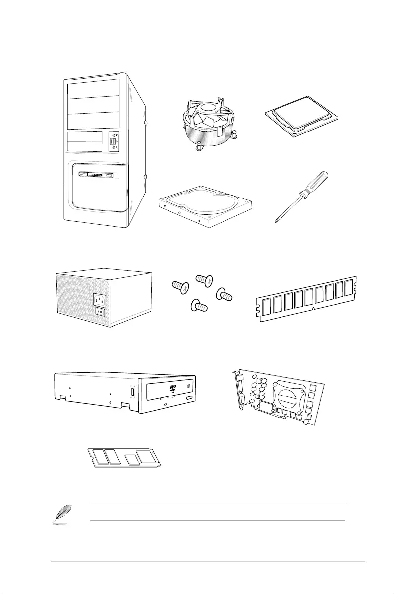
Installation tools and components
The tools and components in the table above are not included in the motherboard package.
PC chassis
Power supply unit
Intel® LGA 2066 compatible CPU Fan
Intel® LGA 2066 CPU
DIMM
SATA hard disk drive
Graphics card
Phillips (cross) screwdriver
SATA optical disc drive (optional)
M.2 SSD module (optional)
1 bag of screws

xvi

ASUS TUF X299 MARK 1 1-1
Chapter 1
Product Introduction
1
Chapter 1: Product Introduction
• Unplugthepowercordfromthewallsocketbeforetouchinganycomponent.
• Beforehandlingcomponents,useagroundedwriststraportouchasafelygrounded
objectorametalobject,suchasthepowersupplycase,toavoiddamagingthemdue
tostaticelectricity.
• HoldcomponentsbytheedgestoavoidtouchingtheICsonthem.
• Wheneveryouuninstallanycomponent,placeitonagroundedantistaticpadorinthe
bagthatcamewiththecomponent.
• Beforeyouinstallorremoveanycomponent,ensurethattheATXpowersupplyis
switchedofforthepowercordisdetachedfromthepowersupply.Failuretodoso
maycauseseveredamagetothemotherboard,peripherals,orcomponents.
1.1 Motherboard overview
1.1.1 Before you proceed
Takenoteofthefollowingprecautionsbeforeyouinstallmotherboardcomponentsorchange
anymotherboardsettings.
1-2 Chapter 1: Product Introduction
Chapter 1
Referto1.1.9 Internal connectorsand2.3.1 Rear I/O connectionformoreinformation
aboutrearpanelconnectorsandinternalconnectors.
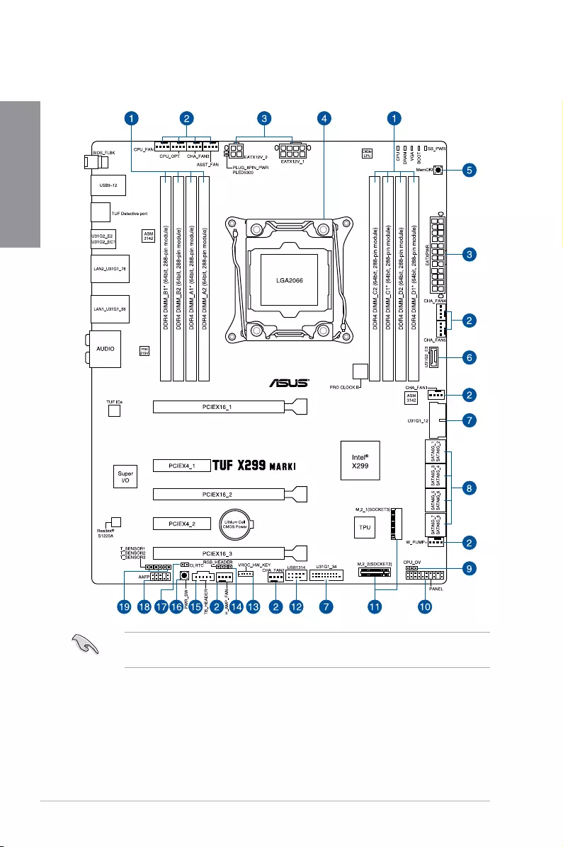
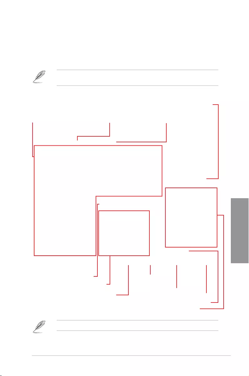
1.1.2 Motherboard layout

ASUS TUF X299 MARK 1 1-3
Chapter 1
Layout contents
Connectors/Jumpers/Buttons and switches/Slots Page
1. DDR4DIMMslots 1-5
2. CPU,CPUoptional,assistant,waterpump+,highamp,andchassisfan
connectors(4-pinCPU_FAN;4-pinCPU_OPT;4-pinASST_FAN;4-pin
W_PUMP+;4-pinH_AMP_FAN;4-pinCHA_FAN1-5)
1-18
3. ATXpowerconnectors(24-pinEATXPWR;8-pinEATX12V_1;4-pin
EATX12V_2)
1-19
4. LGA2066CPUsocket 1-4
5. MemOK!button 1-9
6. USB3.1Gen2frontpanelconnector(U31G2_E3) 1-15
7. USB3.1Gen1connectors(20-1pinU31G1_12;U31G1_34) 1-16
8. Intel®SerialATA6Gb/sconnectors(7-pinSATA6G_12;SATA6G_34;
SATA6G_56;SATA6G_78)
1-14
9. CPUOverVoltagejumper(3-pinCPU_OV) 1-12
10. Systempanelconnector(20-3pinPANEL) 1-20
11. M.2sockets(M.2_1(Socket3);M.2_2(Socket3)) 1-22
12. USB2.0connector(10-1pinUSB1314) 1-17
13. VROC_HW_KEYconnector(4-pinVROC_KEY) 1-21
14. RGBheader(4-pinRGB_HEADER) 1-23
15. Thunderboltheader(5-pinTB_HEADER) 1-21
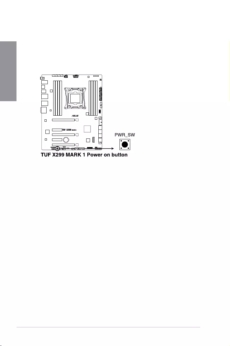
16. Power-onbutton 1-10
17. ClearRTCRAMjumper(2-pinCLRTC) 1-11
18. Frontpanelaudioconnector(10-1pinAAFP) 1-15
19. Thermalsensorconnector(2-pinT_SENSOR1-3) 1-17
1-4 Chapter 1: Product Introduction
Chapter 1
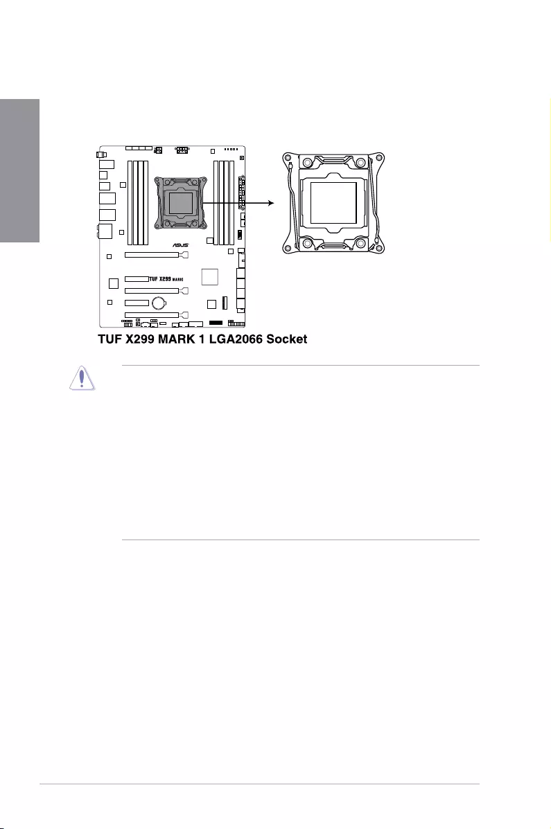
1.1.3 Central Processing Unit (CPU)
ThemotherboardcomeswithasurfacemountLGA2066socketdesignedfortheIntel®
Core™X-seriesProcessors.
• EnsurethatallpowercablesareunpluggedbeforeinstallingtheCPU.
• Uponpurchaseofthemotherboard,ensurethatthePnPcapisonthesocketand
thesocketcontactsarenotbent.ContactyourretailerimmediatelyifthePnPcap
ismissing,orifyouseeanydamagetothePnPcap/socketcontacts/motherboard
components.ASUSwillshoulderthecostofrepaironlyifthedamageisshipment/
transit-related.
• Keepthecapafterinstallingthemotherboard.ASUSwillprocessReturnMerchandise
Authorization(RMA)requestsonlyifthemotherboardcomeswiththecaponthe
LGA2066socket.
• Theproductwarrantydoesnotcoverdamagetothesocketcontactsresultingfrom
incorrectCPUinstallation/removal,ormisplacement/loss/incorrectremovalofthePnP
cap.
ASUS TUF X299 MARK 1 1-5
Chapter 1
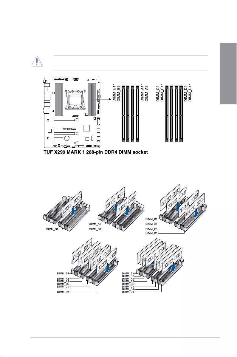
Recommended memory configurations
Intel® Core™ X-series Processors (6-core or above)
1.1.4 System memory
ThemotherboardcomeswitheightDDR4(DoubleDataRate4)DualInlineMemoryModules
(DIMM)slots.
ADDR4moduleisnotcheddifferentlyfromaDDR,DDR2,orDDR3module.DONOT
installaDDR,DDR2,orDDR3memorymoduletotheDDR4slot.
1-6 Chapter 1: Product Introduction
Chapter 1
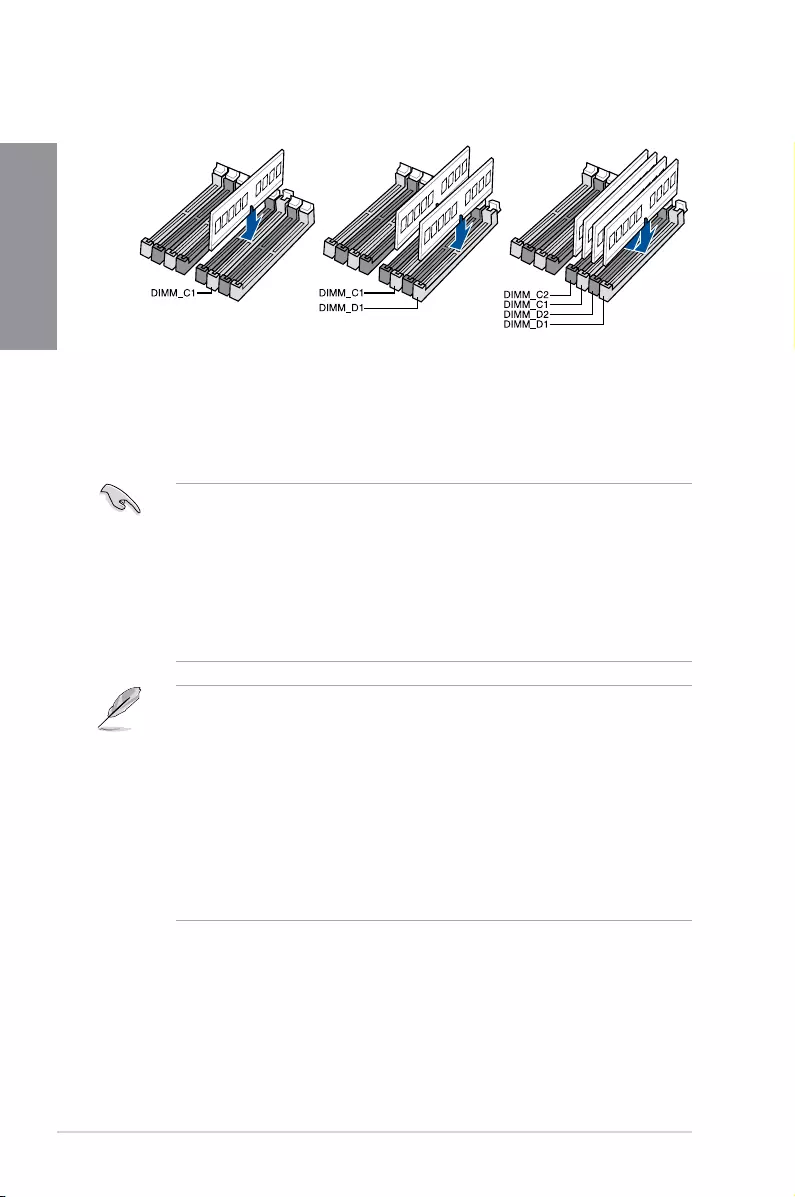
Memory configurations
Youmayinstall2GB,4GB,8GBand16GBunbufferedandnon-ECCDDR4DIMMsinto
theDIMMsockets.
• ForIntel®Core™X-SeriesProcessors(4-core),youmayinstallvaryingmemorysizes
inChannelCandChannelD.Thesystemmapsthetotalsizeofthelower-sized
channelforthedual-channelconguration.Anyexcessmemoryfromthehigher-sized
channelisthenmappedforsingle-channeloperation.
• ForIntel®Core™X-SeriesProcessors(6-coreorabove),youmayinstallvarying
memorysizesinChannelA,ChannelB,ChannelC,andChannelD.Thesystem
mapsthetotalsizeofthelower-sizedchannelforthequad-channelconguration.
Anyexcessmemoryfromthehigher-sizedchannelisthenmappedforsingle-channel
operation.
• ThedefaultmemoryoperationfrequencyisdependentonitsSerialPresenceDetect
(SPD),whichisthestandardwayofaccessinginformationfromamemorymodule.
Underthedefaultstate,somememorymodulesforoverclockingmayoperateata
lowerfrequencythanthevendor-markedvalue.
• Forsystemstability,useamoreefcientmemorycoolingsystemtosupportafull
memoryload(8DIMMs)oroverclockingcondition.
• AlwaysinstalltheDIMMSwiththesameCASLatency.Foranoptimumcompatibility,
werecommendthatyouinstallmemorymodulesofthesameversionordatacode
(D/C)fromthesamevendor.Checkwiththevendortogetthecorrectmemory
modules.
• VisittheASUSwebsiteforthelatestQVL.
Intel® Core™ X-series Processors (4-core)
ASUS TUF X299 MARK 1 1-7
Chapter 1
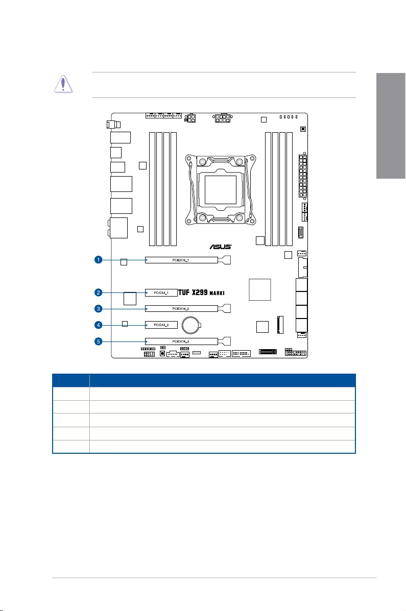
1.1.5 Expansion slots
Unplugthepowercordbeforeaddingorremovingexpansioncards.Failuretodosomay
causeyouphysicalinjuryanddamagemotherboardcomponents.
Slot No. Slot Description
1PCIE3.0/2.0x16_1slot
2PCIE3.0/2.0x4_1slot
3PCIE3.0/2.0x16_2slot
4PCIE3.0/2.0x4_2slot
5PCIE3.0/2.0x16_3slot

1-8 Chapter 1: Product Introduction
Chapter 1
WerecommendthatyouprovidesufcientpowerwhenrunningCrossFireX™orSLI™
mode.
PCI Express 3.0 operating mode
VGA / PCIe
configuration
Single VGA /
PCIe card
Dual VGA /
PCIe cards
Triple VGA /
PCIe cards
PCIe 3.0/2.0 x16_1
x16
(singleVGA
recommended)
x16 x16
PCIe 3.0/2.0 x16_2 N/A x16 x16
PCIe 3.0/2.0 x16_3 N/A N/A x8
PCI Express 3.0 operating mode
VGA / PCIe
configuration
Single VGA /
PCIe card
Dual VGA /
PCIe cards
PCIe 3.0/2.0 x16_1 x16(singleVGA
recommended) x16
PCIe 3.0/2.0 x16_2 N/A x8
PCIe 3.0/2.0 x16_3 N/A N/A
PCI Express 3.0 operating mode
VGA / PCIe
configuration
Single VGA /
PCIe card
Dual VGA /
PCIe cards
PCIe 3.0/2.0 x16_1 x16(singleVGA
recommended) x8
PCIe 3.0/2.0 x16_2 N/A x8
PCIe 3.0/2.0 x16_3 N/A N/A
44-Lane CPUs
28-Lane CPUs
16-Lane CPUs
ASUS TUF X299 MARK 1 1-9
Chapter 1
1.1.6 Onboard buttons and switches
Onboardbuttonsandswitchesallowyoutone-tuneperformancewhenworkingonabareor
open-casesystem.Thisisidealforoverclockersandgamerswhocontinuallychangesettings
toenhancesystemperformance.
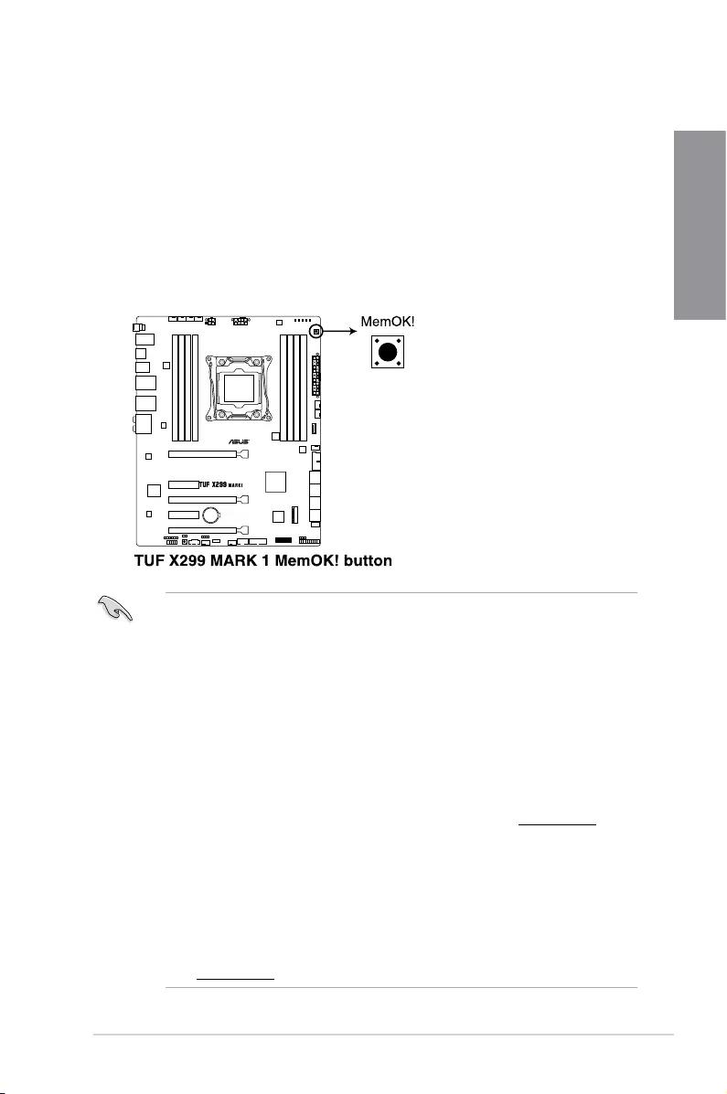
1. MemOK! button
InstallingDIMMsthatarenotcompatiblewiththemotherboardmaycausesystemboot
failure.IfthesystemfailstobootduringPOSTstageandtheDRAM_LEDnearthe
MemOK!buttonlightscontinuously,presstheMemOK!buttonuntiltheDRAM_LED
startsblinking.Systemwillbeginautomaticmemorycompatibilitytuningandrebootfor
successfulboot.
• Refertosection1.1.8 Onboard LEDsfortheexactlocationoftheDRAM_LED.
• TheDRAM_LEDalsolightsupwhentheDIMMisnotproperlyinstalled.Turnoffthe
systemandreinstalltheDIMMbeforeusingtheMemOK!function.
• TheMemOK!buttondoesnotfunctionunderWindows®OSenvironment.
• Duringthetuningprocess,thesystemloadsandtestsfailsafememorysettings.It
takesabout30secondsforthesystemtotestonesetoffailsafesettings.Ifthetest
fails,thesystemrebootsandteststhenextsetoffailsafesettings.Theblinkingspeed
oftheDRAM_LEDincreases,indicatingdifferenttestprocesses.
• Duetomemorytuningrequirement,thesystemautomaticallyrebootswheneach
timingsetistested.IftheinstalledDIMMsstillfailtobootafterthewholetuning
process,theDRAM_LEDlightscontinuously.ReplacetheDIMMswithones
recommendedintheMemoryQVL(QualiedVendorsLists)atwww.asus.com.
• IfyouturnoffthecomputerandreplaceDIMMsduringthetuningprocess,thesystem
continuesmemorytuningafterturningonthecomputer.Tostopmemorytuning,turn
offthecomputerandunplugthepowercordforabout5–10seconds.
• IfyoursystemfailstobootupduetoBIOSoverclocking,presstheMemOK!button
tobootandloadtheBIOSdefaultsettings.AmessagewillappearduringPOST
remindingyouthattheBIOShasbeenrestoredtoitsdefaultsettings.
• WerecommendthatyoudownloadandupdatetothelatestBIOSversionfrom
www.asus.comafterusingtheMemOK!function.
1-10 Chapter 1: Product Introduction
Chapter 1
2. Power-on button
Themotherboardcomeswithapower-onbuttonthatallowsyoutopoweruporwake
upthesystem.TheStandbyPowerLED(SB_PWR)alsolightsupwhenthesystemis
pluggedtoapowersourceindicatingthatyoushouldshutdownthesystemandunplug
thepowercablebeforeremovingorinstallinganymotherboardcomponent.
ASUS TUF X299 MARK 1 1-11
Chapter 1
1.1.7 Jumpers
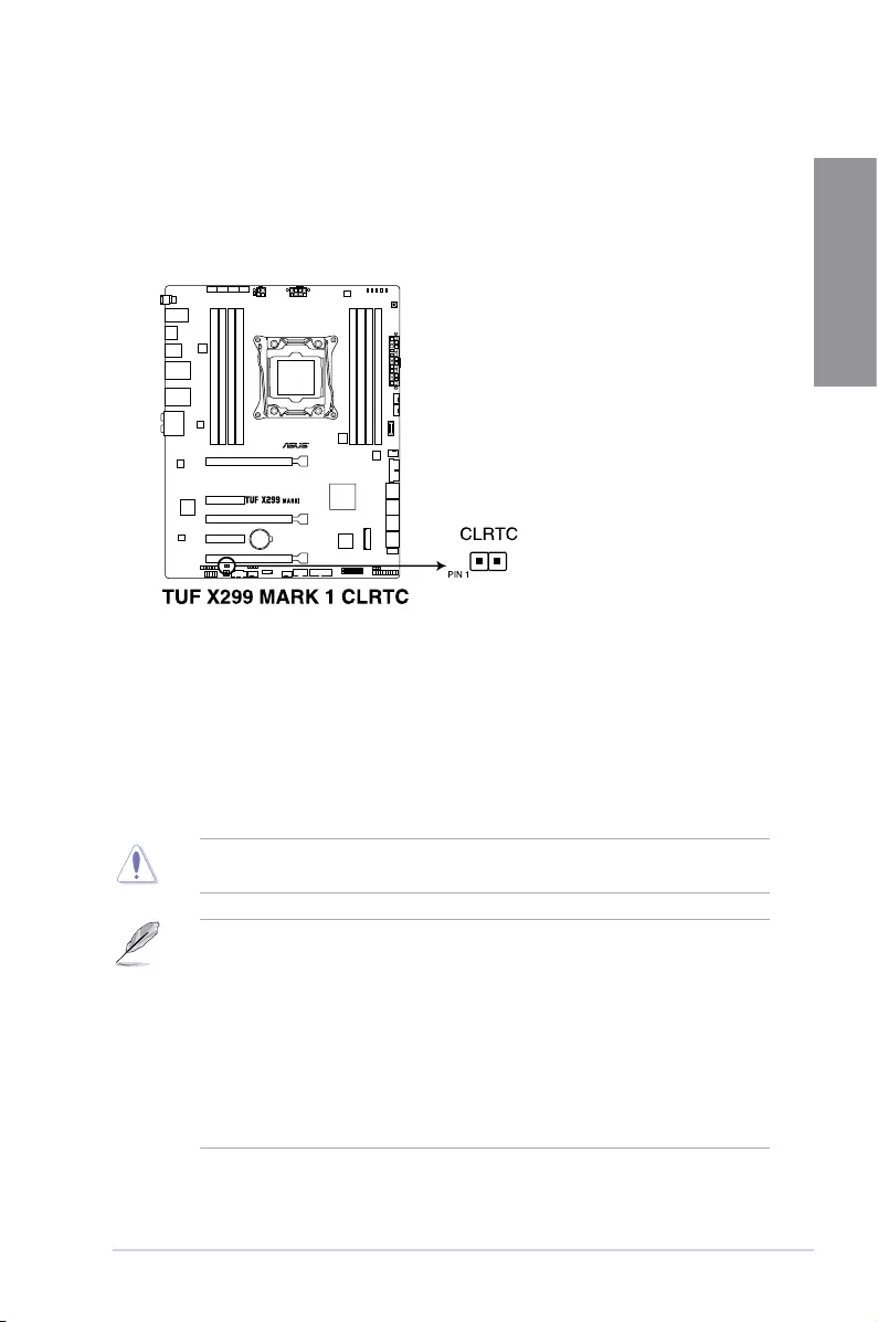
1. Clear RTC RAM jumper (2-pin CLRTC)
ThisjumperallowsyoutocleartheRealTimeClock(RTC)RAMinCMOS.Youcan
cleartheCMOSmemoryofdate,time,andsystemsetupparametersbyerasingthe
CMOSRTCRAMdata.TheonboardbuttoncellbatterypowerstheRAMdatain
CMOS,whichincludesystemsetupinformationsuchassystempasswords.
ToerasetheRTCRAM:
1. TurnOFFthecomputerandunplugthepowercord.
2. Short-circuitpin1-2withametalobjectorjumpercapforabout5-10seconds.
3. PlugthepowercordandturnONthecomputer.
4. Holddownthe<Delete>keyduringthebootprocessandenterBIOSsetuptore-enter
data.
ExceptwhenclearingtheRTCRAM,neverplaceametalobjectorjumpercaponthe
CLRTCjumper.Placingametalobjectorjumpercapwillcausesystembootfailure!
• Ifthestepsabovedonothelp,removetheonboardbatteryandplaceametalobject
orjumpercapagaintocleartheCMOSRTCRAMdata.AftertheCMOSclearance,
reinstallthebattery.
• YoudonotneedtocleartheRTCwhenthesystemhangsduetooverclocking.For
systemfailureduetooverclocking,usetheC.P.R.(CPUParameterRecall)feature.
ShutdownandrebootthesystemsotheBIOScanautomaticallyresetparameter
settingstodefaultvalues.
• Duetothechipsetbehavior,ACpoweroffisrequiredtoenableC.P.R.function.You
mustturnoffandturnonthepowersupplyorunplugandplugthepowercordbefore
rebootingthesystem.
1-12 Chapter 1: Product Introduction
Chapter 1
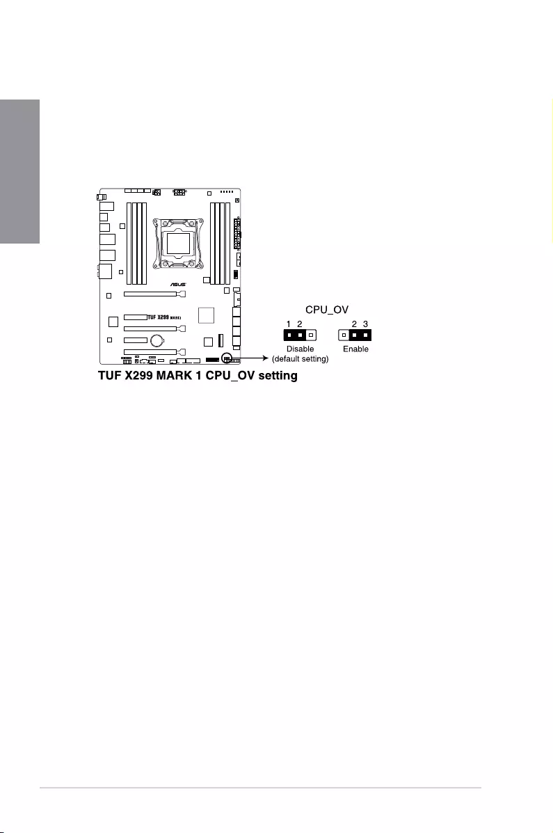
2. CPU Over Voltage jumper (3-pin CPU_OV)
TheCPUOverVoltagejumperallowsyoutosetahigherCPUvoltageforaexible
overclockingsystem,dependingonthetypeoftheinstalledCPU.TogainmoreCPU
voltagesetting,insertthejumpertopins2-3.TogobacktoitsdefaultCPUvoltage
setting,insertthejumpertopins1-2.
ASUS TUF X299 MARK 1 1-13
Chapter 1
1.1.8 Onboard LEDs
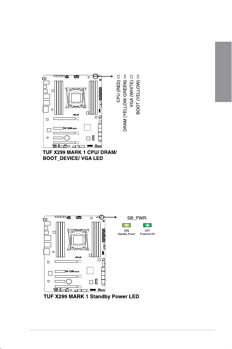
1. POST State LEDs
ThePOSTStateLEDsprovidethestatusofthesekeycomponentsduringPOST
(Power-OnSelf-Test):CPU,memorymodules,VGAcard,andharddiskdrives.Ifan
errorisfound,thecriticalcomponent’sLEDstayslitupuntiltheproblemissolved.
2. Standby Power LED
ThemotherboardcomeswithastandbypowerLED.TheLEDlightsuptoindicatethat
thesystemisON,insleepmode,orinsoft-offmode.Thisisareminderthatyoushould
shutdownthesystemandunplugthepowercablebeforeremovingorplugginginany
motherboardcomponent.TheillustrationbelowshowsthelocationoftheonboardLED.
1-14 Chapter 1: Product Introduction
Chapter 1
1.1.9 Internal connectors
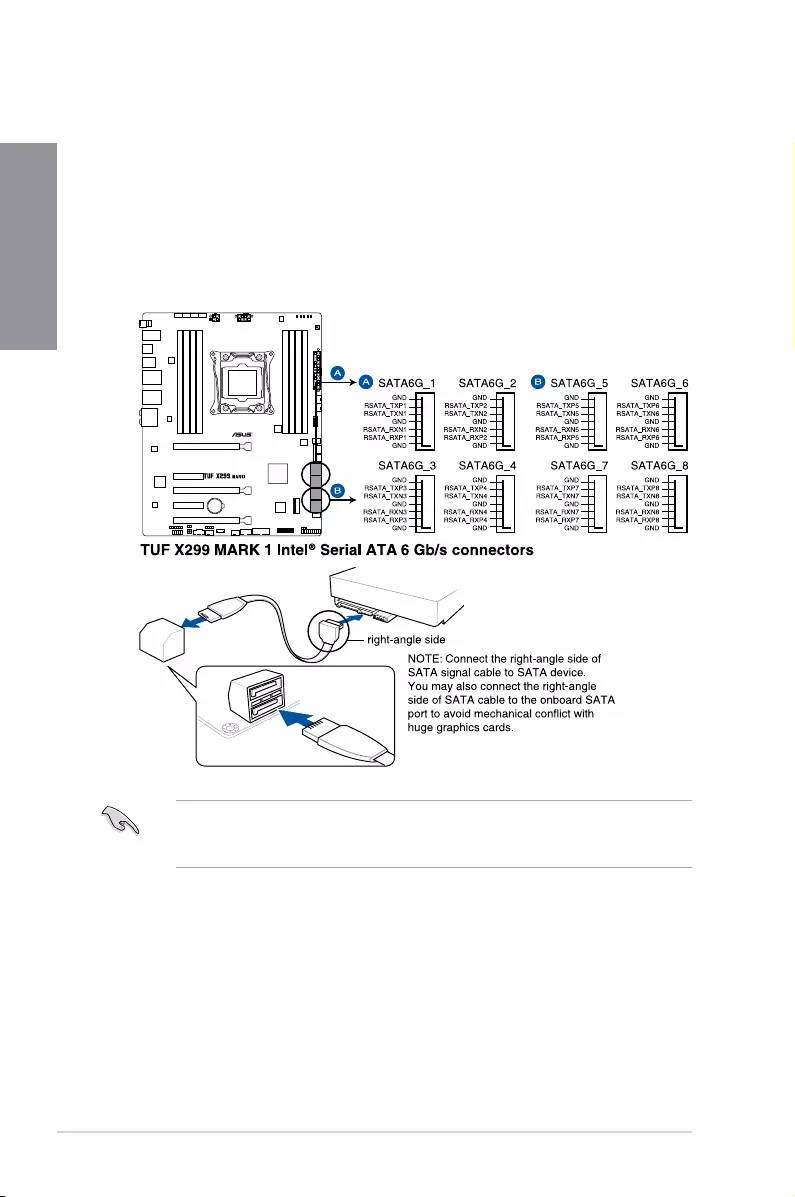
1. Intel® Serial ATA 6 Gb/s connectors (7-pin SATA6G_12; SATA 6G_34;
SATA 6G_56; SATA 6G_78)
TheseconnectorsconnecttoSerialATA6Gb/sharddiskdrivesviaSerialATA6Gb/s
signalcables.
IfyouinstalledSerialATAharddiskdrives,youcancreateaRAID0,1,5,and10
congurationwiththeIntel®RapidStorageTechnologythroughtheonboardIntel®
X299chipset.
Theseconnectorsaresetto[AHCI Mode]bydefault.IfyouintendtocreateaSerialATA
RAIDsetusingtheseconnectors,settheSATAModeitemintheBIOSto[Intel RST
Premium With Intel Optane System Acceleration (RAID)].
ASUS TUF X299 MARK 1 1-15
Chapter 1
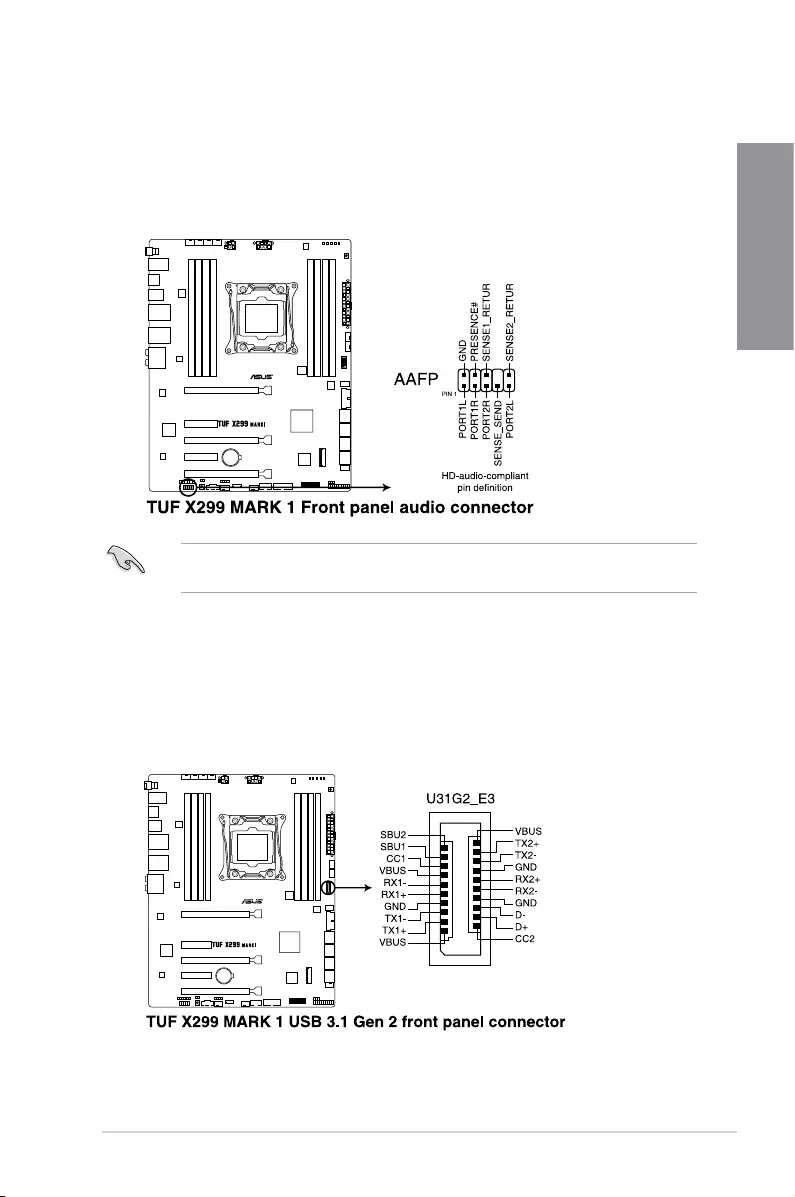
2. Front panel audio connector (10-1 pin AAFP)
Thisconnectorisforachassis-mountedfrontpanelaudioI/OmodulethatsupportsHD
Audio.ConnectoneendofthefrontpanelaudioI/Omodulecabletothisconnector.
Werecommendthatyouconnectahigh-denitionfrontpanelaudiomoduletothis
connectortoavailofthemotherboard’shigh-denitionaudiocapability.
3. USB 3.1 Gen 2 front panel connector (U31G2_E3)
ThisconnectorallowsyoutoconnectaUSB3.1Gen2moduleforadditionalUSB3.1
Gen2ports.ThelatestUSB3.1Gen2connectivityprovidesdatatransferspeedsof
upto10Gbps.
1-16 Chapter 1: Product Introduction
Chapter 1
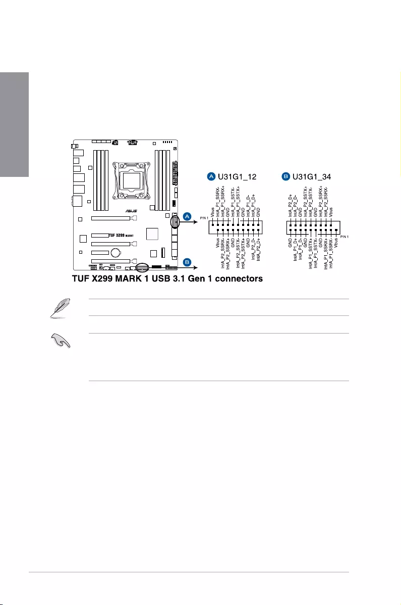
4. USB 3.1 Gen 1 connectors (20-1 pin U31G1_12; U31G1_34)
TheseconnectorsallowyoutoconnectaUSB3.1Gen1moduleforadditionalUSB
3.1Gen1frontorrearpanelports.WithaninstalledUSB3.1Gen1module,youcan
enjoyallthebenetsofUSB3.1Gen1includingfasterdatatransferspeedsofupto
5Gb/s,fasterchargingtimeforUSB-chargeabledevices,optimizedpowerefciency,
andbackwardcompatibilitywithUSB2.0.
TheUSB3.1Gen1moduleispurchasedseparately.
• EnsuretoinstalltherelateddrivertofullyusetheUSB3.1Gen1portsunder
Windows®7.
• ThepluggedUSB3.1Gen1devicemayrunonxHCIorEHCImodedependingonthe
operatingsystem’ssetting.
ASUS TUF X299 MARK 1 1-17
Chapter 1
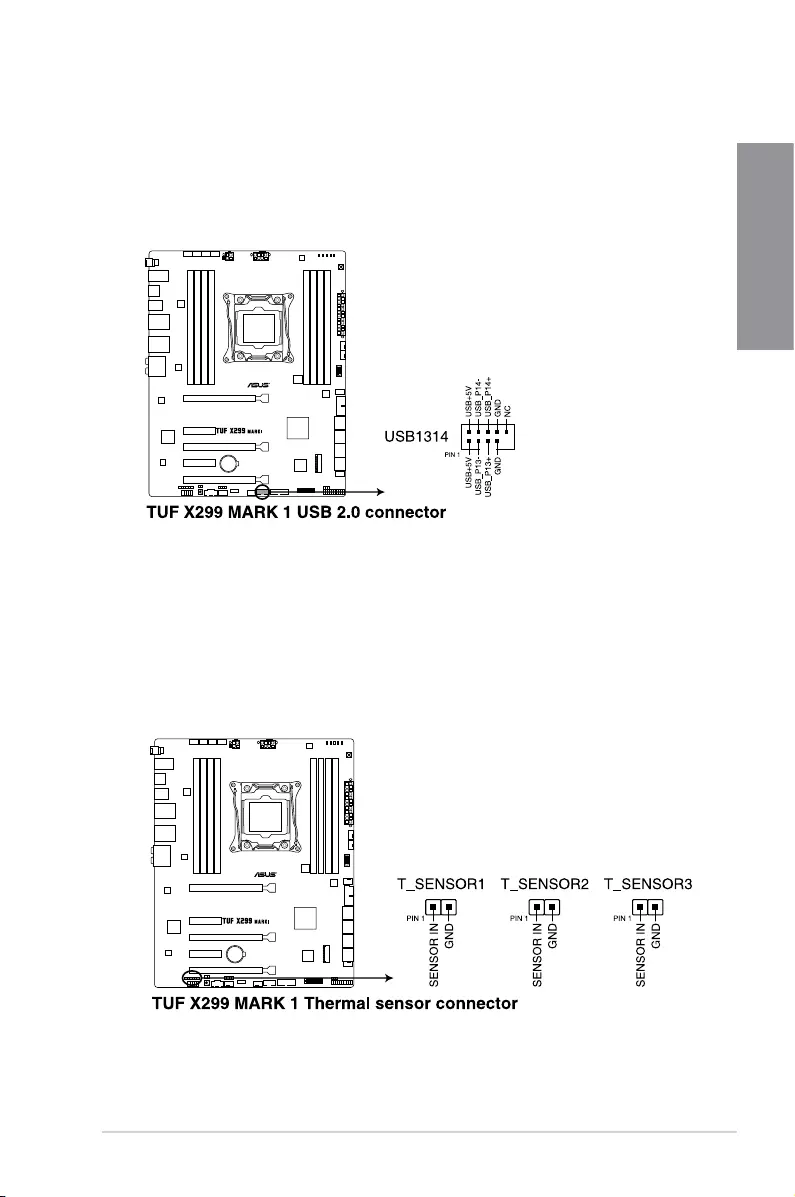
5. USB 2.0 connector (10-1 pin USB1314)
ThisconnectorisforUSB2.0ports.ConnecttheUSBmodulecabletothisconnector,
theninstallthemoduletoaslotopeningatthebackofthesystemchassis.ThisUSB
connectorcomplieswithUSB2.0specicationthatsupportsupto480Mb/sconnection
speed.
6. Thermal sensor connector (2-pin T_SENSOR1-3)
Theseconnectorsareforthethermistorcablethatmonitorsthetemperatureofthe
devicesandthecriticalcomponentsinsidethemotherboard.Connectthethermistor
cableandplacethesensoronthedeviceorthemotherboard’scomponenttodetectits
temperature.
1-18 Chapter 1: Product Introduction
Chapter 1
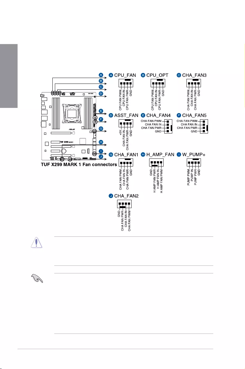
7. CPU, CPU optional, assistant, water pump+, high amp, and chassis fan
connectors (4-pin CPU_FAN; 4-pin CPU_OPT; 4-pin ASST_FAN; 4-pin W_PUMP+;
4-pin H_AMP_FAN; 4-pin CHA_FAN1-5)
Connectthefancablestothefanconnectorsonthemotherboard,ensuringthatthe
blackwireofeachcablematchesthegroundpinoftheconnector.
• TheCPU_FANconnectorsupportstheCPUfanofmaximum1A(12W)fanpower.
• TheCPU_FAN,CHA_FANandASST_FANconnectorssupporttheTUFThermal
Radar3feature.
• ForbetterQ-Fanfunctions,werecommendusing4-pinPWMfanswhenyouconnect
powerfulfans(1Aorabove)ontotheH_AMP_FANconnector.
• EnsuretodisableQ-Fanfunctionsifyouwanttoconnectpowerful3-pinDCfans(1A
orabove)ontotheH_AMP_FANconnector.
• W_PUMP+functionsupportdependsonwatercoolingdevice.
• DONOTforgettoconnectthefancablestothefanconnectors.Insufcientairow
insidethesystemmaydamagethemotherboardcomponents.Thesearenotjumpers!
Donotplacejumpercapsonthefanconnectors!
• EnsurethattheCPUfancableissecurelyinstalledtotheCPUfanconnector.
ASUS TUF X299 MARK 1 1-19
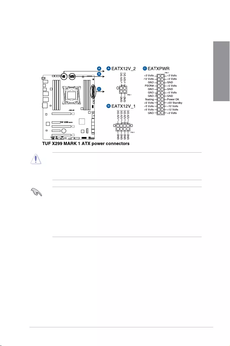
Chapter 1
8. ATX power connectors (24-pin EATXPWR; 8-pin EATX12V_1; 4-pin EATX12V_2)
TheseconnectorsareforATXpowersupplyplugs.Thepowersupplyplugsare
designedtottheseconnectorsinonlyoneorientation.Findtheproperorientationand
pushdownrmlyuntiltheconnectorscompletelyt.
• DONOTconnectthe4-pinpowerplugonly,themotherboardmayoverheatunder
heavyusage.
• Ensuretoconnectthe8-pinpowerplug,orconnectboththe8-pinand4-pinpower
plugs.
• Forafullyconguredsystem,werecommendthatyouuseapowersupplyunit
(PSU)thatcomplieswithATX12VSpecication2.0(orlaterversion)andprovidesa
minimumpowerof350W.
• WerecommendthatyouuseaPSUwithahigherpoweroutputwhenconguringa
systemwithmorepower-consumingdevices.Thesystemmaybecomeunstableor
maynotbootupifthepowerisinadequate.
• Ifyouwanttousetwoormorehigh-endPCIExpressx16cards,useaPSUwith
1000Wpowerorabovetoensurethesystemstability.
1-20 Chapter 1: Product Introduction
Chapter 1
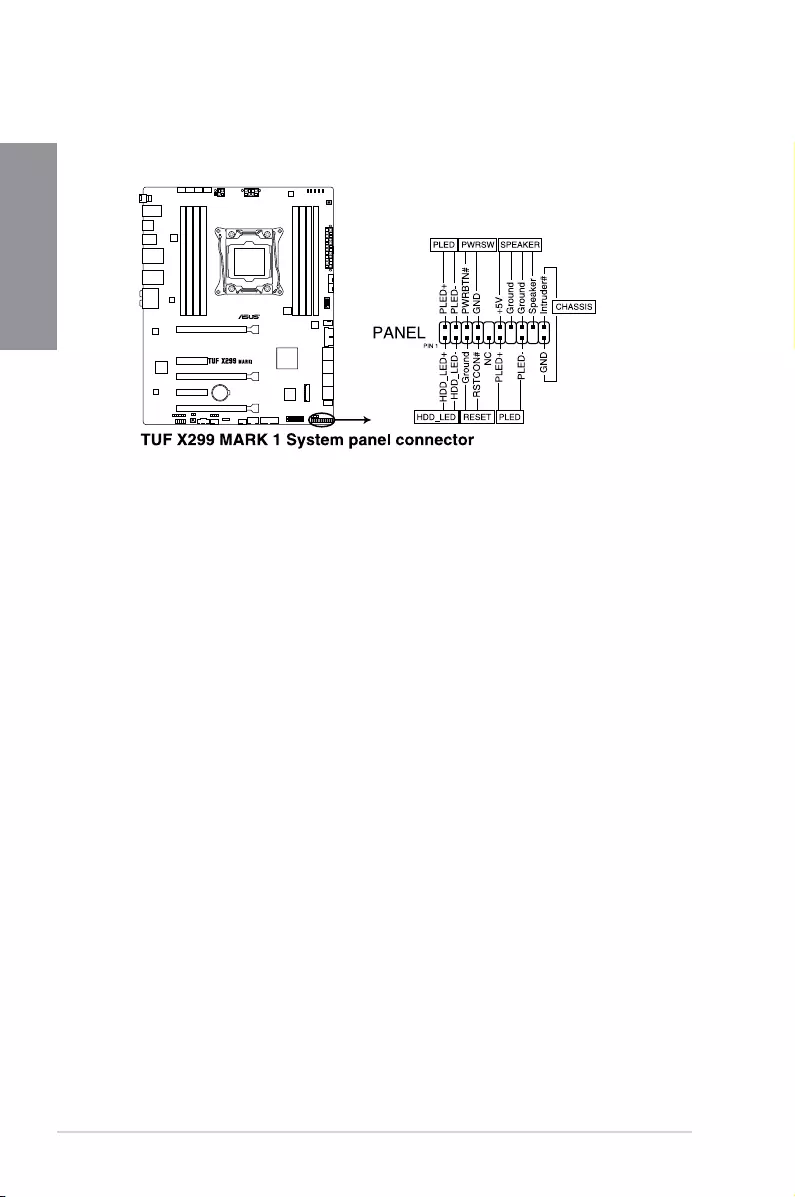
• SystempowerLED(2-pinor3-1pinPLED)
The2-pinor3-1pinconnectorisforthesystempowerLED.Connectthechassis
powerLEDcabletothisconnector.ThesystempowerLEDlightsupwhenyouturnon
thesystempower,andblinkswhenthesystemisinsleepmode.
• HarddiskdriveactivityLED(2-pinHDD_LED)
This2-pinconnectorisfortheHDDActivityLED.ConnecttheHDDActivityLEDcable
tothisconnector.TheHDDLEDlightsuporasheswhendataisreadfromorwritten
totheHDD.
• Systemwarningspeaker(4-pinSPEAKER)
This4-pinconnectorisforthechassis-mountedsystemwarningspeaker.Thespeaker
allowsyoutohearsystembeepsandwarnings.
• ATXpowerbutton/soft-offbutton(2-pinPWRSW)
Thisconnectorisforthesystempowerbutton.Pressingthepowerbuttonturnsthe
systemonorputsthesysteminsleeporsoft-offmodedependingontheoperating
systemsettings.Pressingthepowerswitchformorethanfoursecondswhilethe
systemisONturnsthesystemOFF.
• Resetbutton(2-pinRESET)
This2-pinconnectorisforthechassis-mountedresetbuttonforsystemrebootwithout
turningoffthesystempower.
• Chassisintrusionconnector(2-pinCHASSIS)
Thisconnectorisforachassis-mountedintrusiondetectionsensororswitch.Connect
oneendofthechassisintrusionsensororswitchcabletothisconnector.Thechassis
intrusionsensororswitchsendsahigh-levelsignaltothisconnectorwhenachassis
componentisremovedorreplaced.Thesignalisthengeneratedasachassisintrusion
event.
9. System panel connector (20-3 pin PANEL)
Thisconnectorsupportsseveralchassis-mountedfunctions.
ASUS TUF X299 MARK 1 1-21
Chapter 1
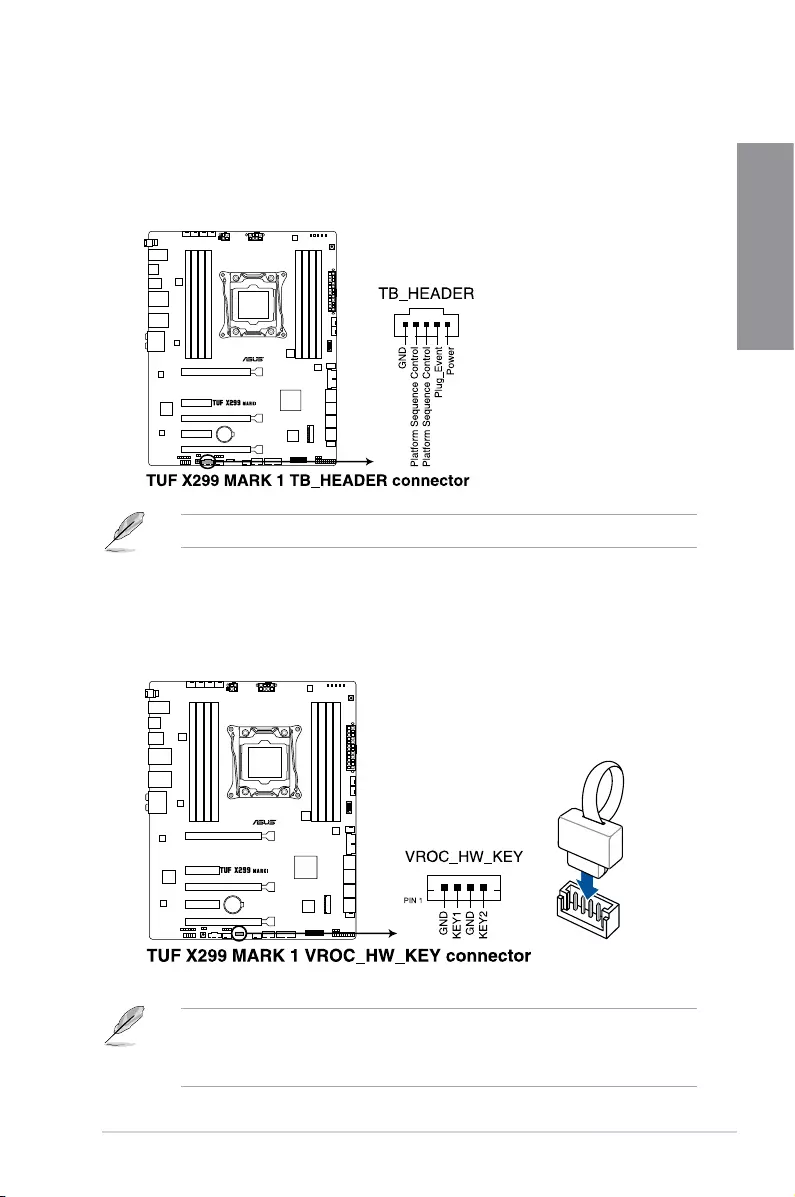
10. Thunderbolt header (5-pin TB_HEADER)
Thisconnectorisfortheadd-onThunderboltI/OcardthatsupportsIntel’sThunderbolt
Technology,allowingyoutoconnectuptosixThunderbolt-enableddevicesanda
DisplayPort-enableddisplayinadaisy-chainconguration.
Theadd-onThunderboltI/OcardandThunderboltcablesarepurchasedseparately.
11. VROC_HW_KEY connector (4-pin VROC_KEY)
ThisconnectorallowsyoutoconnectaKEYmoduletoenableCPURAIDfunctions
withIntel®CPURSTe.
• TheKEYmoduleispurchasedseparately.
• DuetoCPUbehavior,CPURAIDfunctionswithIntel®CPURSTeonlysupportsIntel®
Core™X-seriesProcessors(6-coreorabove)andIntel®SSDmodules.

1-22 Chapter 1: Product Introduction
Chapter 1
12. M.2sockets(M.2_1(Socket3);M.2_2(Socket3))
ThesesocketsallowyoutoinstallM.2SSDmodules.
• M.2_1socketsupportsPCIe3.0x4andSATAmodeMKeydesignandtype2242/
2260/2280PCIeandSATAstoragedevices.
• M.2_2socketsupportsPCIe3.0x4MKeydesignandtype2242/2260/2280/22110
PCIestoragedevices.
• ThesesocketssupportIRST(Intel®RapidStorageTechnology).
TheM.2SSDmoduleispurchasedseparately.
ASUS TUF X299 MARK 1 1-23
Chapter 1
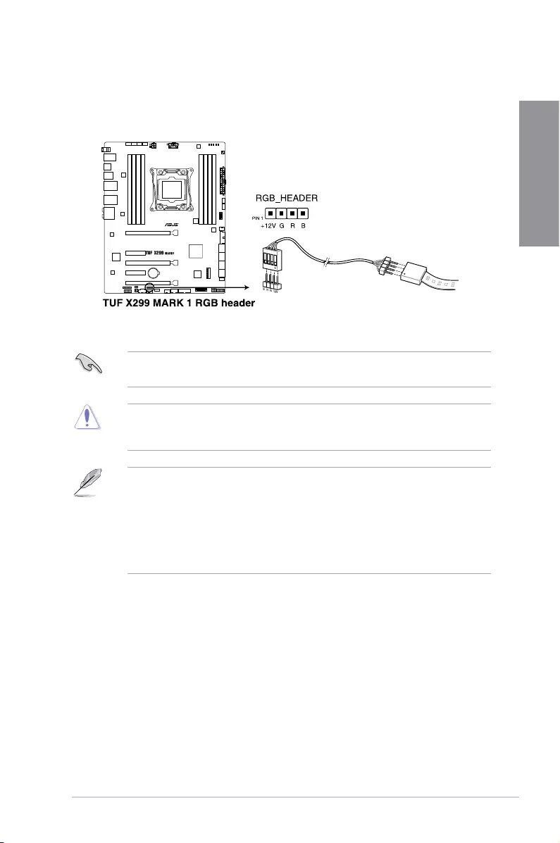
13. RGB header (4-pin RGB_HEADER)
ThisconnectorisforRGBLEDstrips.
TheRGBheadersupports5050RGBmulti-colorLEDstrips(12V/G/R/B),withamaximum
powerratingof2A(12V),andnolongerthan2m.
Beforeyouinstallorremoveanycomponent,ensurethattheATXpowersupplyisswitched
offorthepowercordisdetachedfromthepowersupply.Failuretodosomaycausesevere
damagetothemotherboard,peripherals,orcomponents.
• ActuallightingandcolorwillvarywithLEDstrip.
• IfyourLEDstripdoesnotlightup,checkiftheRGBLEDextensioncableandthe
RGBLEDstripisconnectedinthecorrectorientation,andthe12Vconnectoris
alignedwiththe12Vheaderonthemotherboard.
• TheLEDstripwillonlylightupundertheoperatingsystem.
• TheLEDstripispurchasedseparately.

1-24 Chapter 1: Product Introduction
Chapter 1
ASUS TUF X299 MARK 1 2-1
Chapter 2
Basic Installation
2
Chapter 2: Basic Installation
2.1 Building your PC system
The diagrams in this section are for reference only. The motherboard layout may vary with
models, but the installation steps are the same for all models.
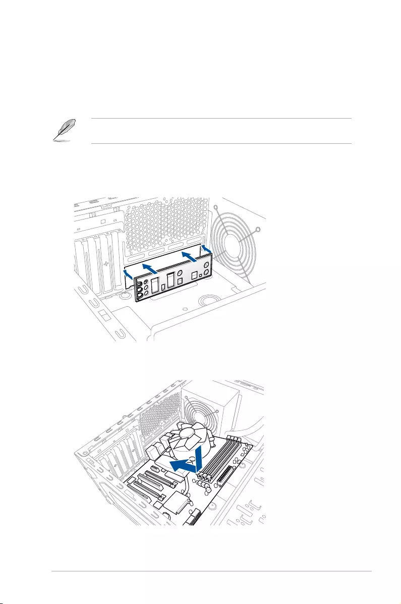
2.1.1 Motherboard installation
1. Install the ASUS Q-Shield to the chassis rear I/O panel.
2. Place the motherboard into the chassis, ensuring that its rear I/O ports are aligned to
the chassis’ rear I/O panel.
2-2 Chapter 2: Basic Installation
Chapter 2
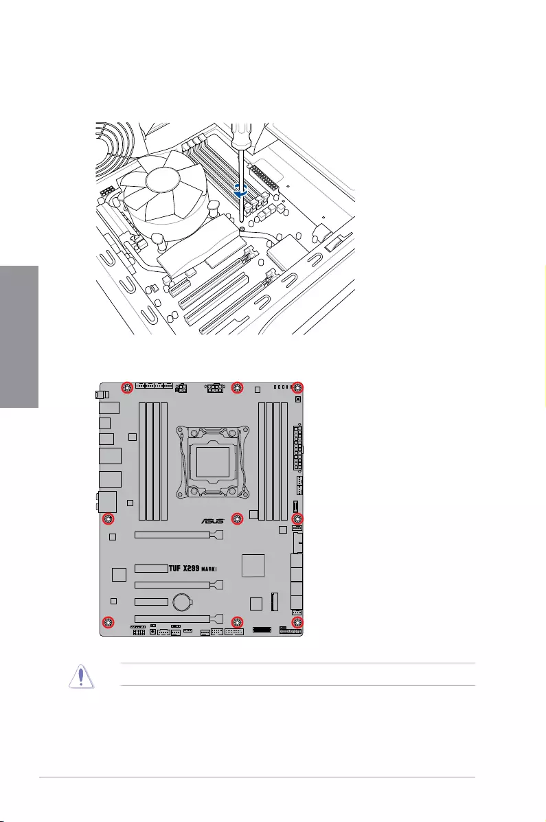
3. Place nine screws into the holes indicated by circles to secure the motherboard to the
chassis.
DO NOT overtighten the screws! Doing so can damage the motherboard.
ASUS TUF X299 MARK 1 2-3
Chapter 2
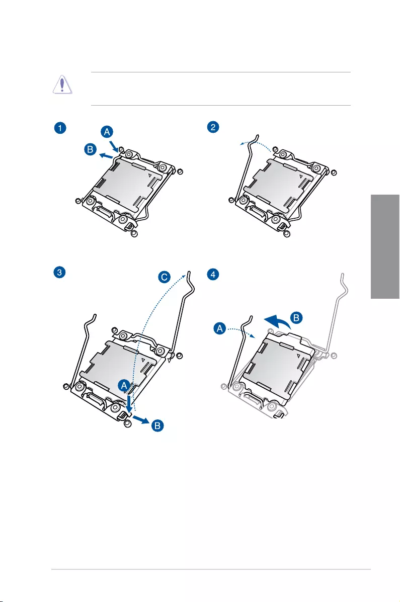
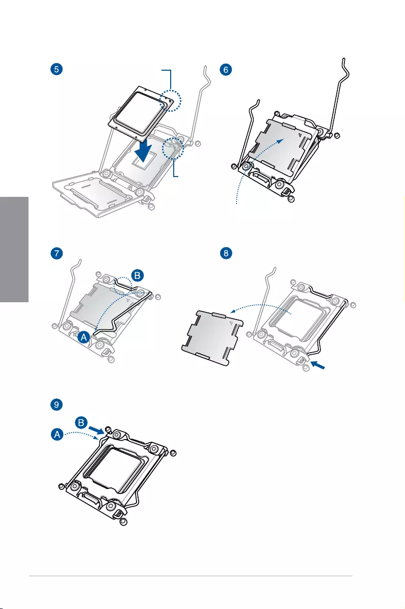
2.1.2 CPU installation
Please note the order in opening/ closing the double latch. Follow the instructions printed
on the metal sealing hatch or the illustrations shown below in this manual. The plastic cap
will pop up automatically once the CPU is in place and the hatch properly sealed down.
2-4 Chapter 2: Basic Installation
Chapter 2
Triangle mark
Triangle
mark
ASUS TUF X299 MARK 1 2-5
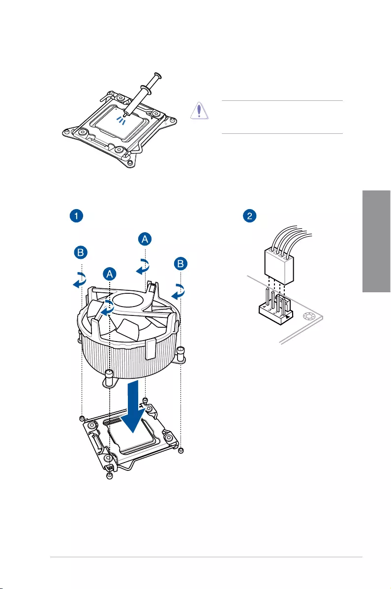
Chapter 2
2.1.3 CPU heatsink and fan assembly installation
Apply the Thermal Interface Material to the
CPU heatsink and CPU before you install
the heatsink and fan, if necessary.
To install the CPU heatsink and fan assembly
2-6 Chapter 2: Basic Installation
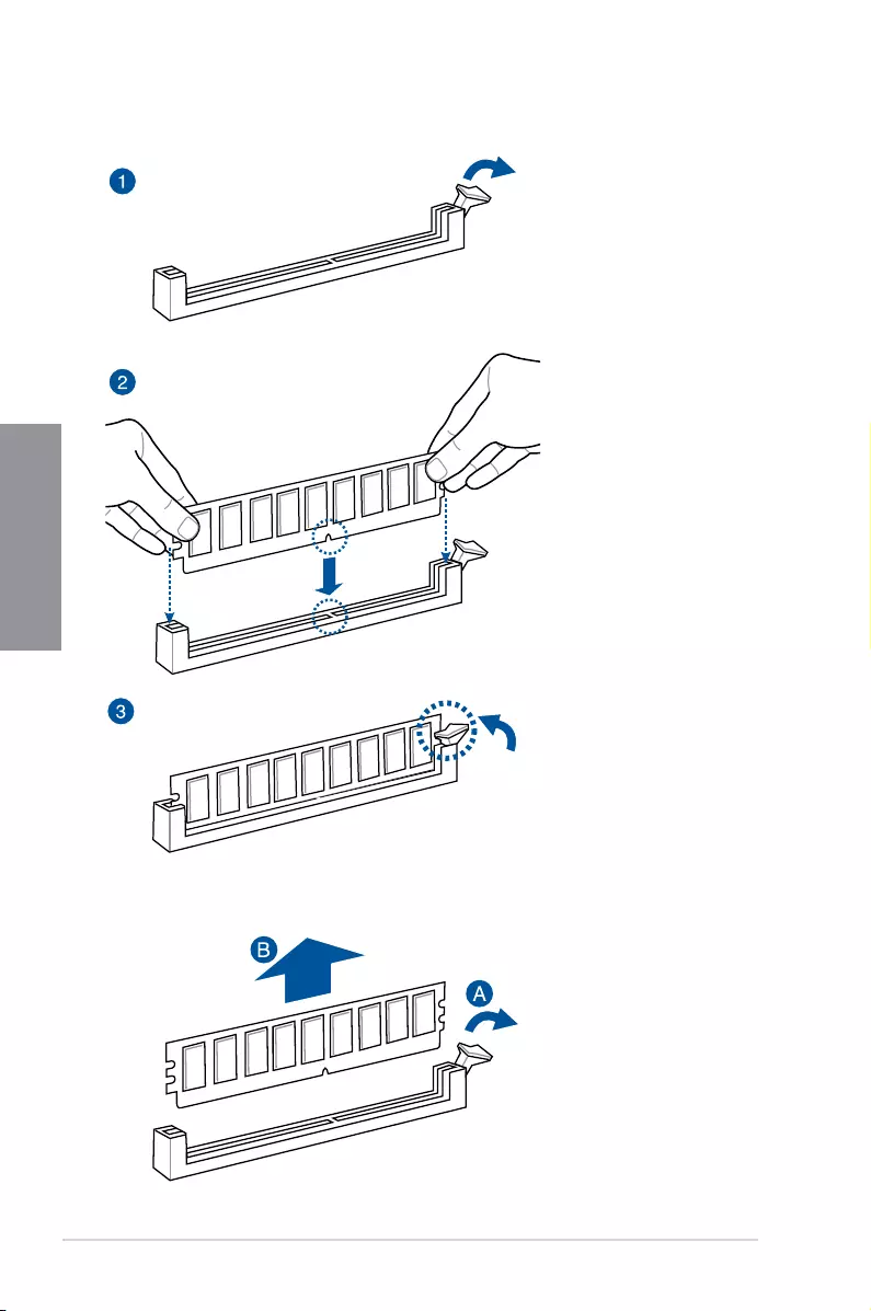
Chapter 2
To remove a DIMM
2.1.4 DIMM installation

ASUS TUF X299 MARK 1 2-7
Chapter 2
2.1.5 ATX power connection
OR AND
• DONOTconnectthe4-pinpowerplugonly,themotherboardmayoverheatunder
heavy usage.
• Ensuretoconnectthe8-pinpowerplug,orconnectboththe8-pinand4-pinpower
plugs.
2-8 Chapter 2: Basic Installation
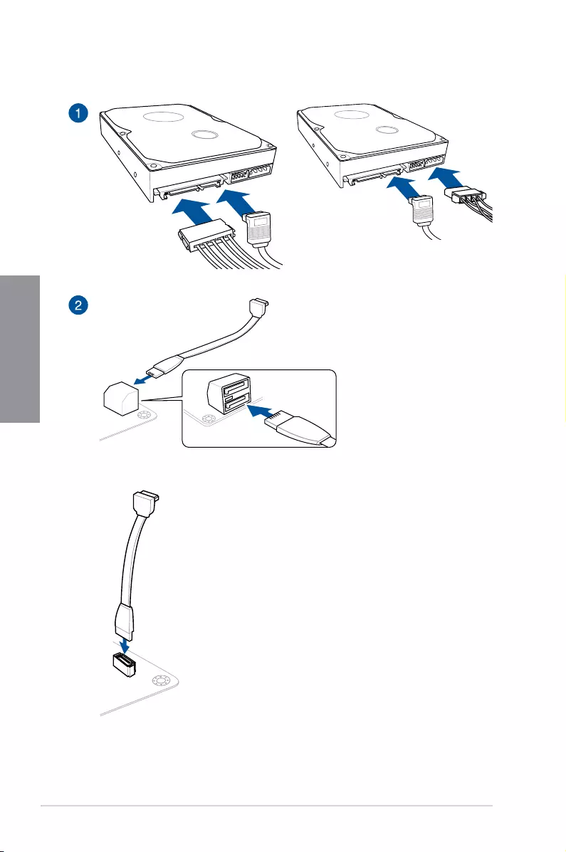
Chapter 2
2.1.6 SATA device connection
OR
OR
ASUS TUF X299 MARK 1 2-9
Chapter 2
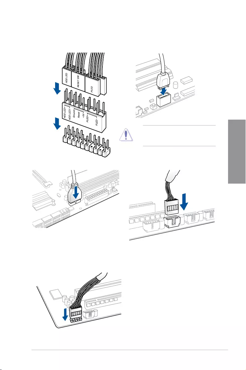
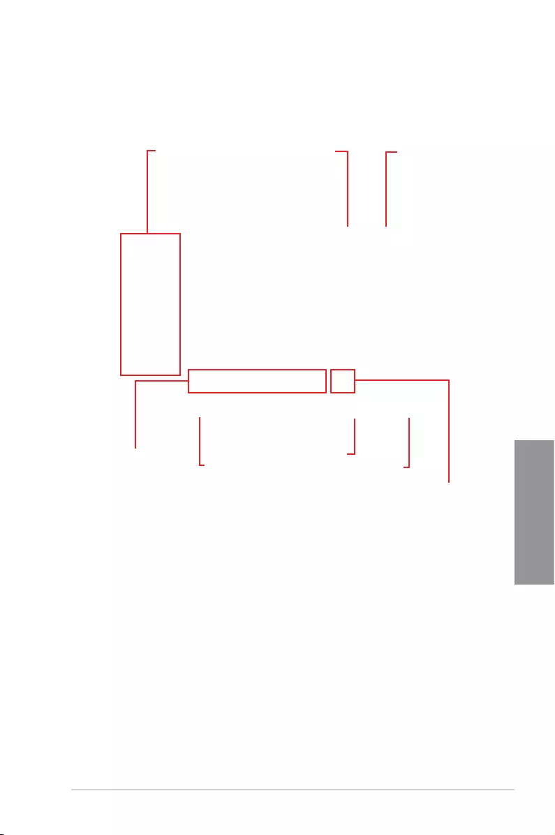
2.1.7 Front I/O connector
USB 3.1 Gen 2
To install USB 3.1 Gen 2 connectorTo install ASUS Q-Connector
Thisconnectorwillonlytinone
orientation. Push the connector until it
clicks into place.
USB 2.0
AAFP
To install USB 2.0 connector
To install front panel audio connector
USB 3.1 Gen 1
To install USB 3.1 Gen 1 connector
2-10 Chapter 2: Basic Installation
Chapter 2
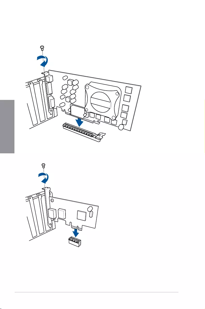
2.1.8 Expansion Card installation
To install PCIe x16 cards
To install PCIe x1 cards
ASUS TUF X299 MARK 1 2-11
Chapter 2
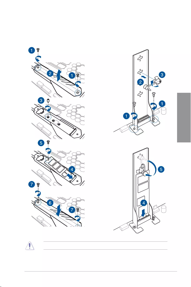
2.1.9 M.2 installation
6
OR
Supported M.2 type varies per motherboard.
2-12 Chapter 2: Basic Installation
Chapter 2
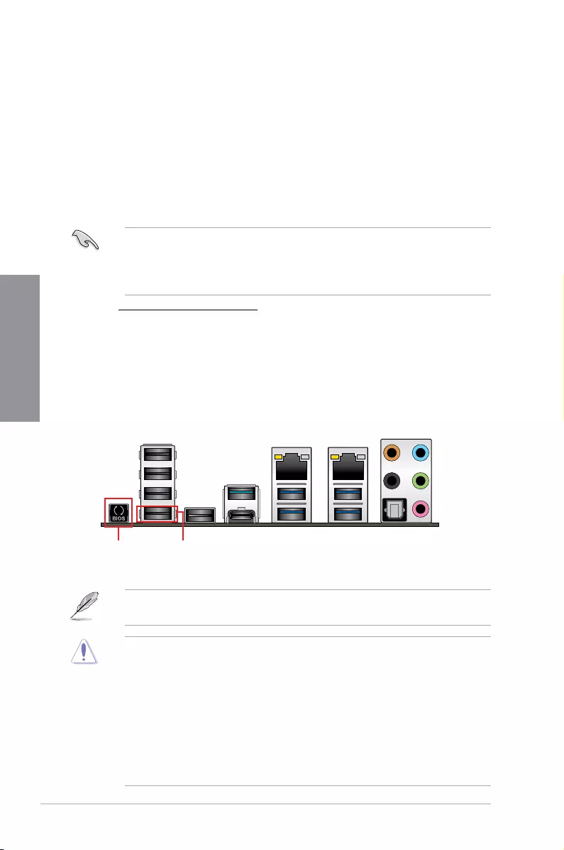
2.2 BIOS update utility
USB BIOS Flashback
USB BIOS Flashback allows you to easily update the BIOS without entering the existing
BIOS or operating system. Simply insert a USB storage device to the USB port (the USB port
hole marked in green on the I/O shield) then press the USB BIOS Flashback button for three
seconds to automatically update the BIOS.
To use USB BIOS Flashback:
1. Insert a USB storage device to the USB Flashback port.
• WerecommendyoutouseaUSB2.0storagedevicetosavethelatestBIOSversion
for better compatibility and stability.
• Refertosection2.3.1 Rear I/O connection for the location of the USB port that
supports USB BIOS Flashback.
2. Visit https://www.asus.com/support/ and download the latest BIOS version for this
motherboard.
3. RenametheleasX299TUF1.CAP, then copy it to your USB storage device.
4. Shut down your computer.
5. PresstheBIOSFlashbackbuttonforthreesecondsuntiltheFlashbackLEDblinks
three times, indicating that the BIOS Flashback function is enabled.
• Donotunplugportabledisk,powersystem,orpresstheCLR_CMOSbuttonwhile
BIOS update is ongoing, otherwise update will be interrupted. In case of interruption,
please follow the steps again.
• Ifthelightashesforvesecondsandturnsintoasolidlight,thismeansthat
the BIOS Flashback is not operating properly. This may be caused by improper
installationoftheUSBstoragedeviceandlename/leformaterror.Ifthisscenario
happens, please restart the system to turn off the light.
• UpdatingBIOSmayhaverisks.IftheBIOSprogramisdamagedduringtheprocess
and results to the system’s failure to boot up, please contact your local ASUS Service
Center.
For more BIOS update utilities in BIOS setup, refer to the section 3.11 Updating BIOS in
Chapter 3.
USB BIOS Flashback portBIOS Flashback button
6. Waituntilthelightgoesout,indicatingthattheBIOSupdatingprocessiscompleted.
ASUS TUF X299 MARK 1 2-13
Chapter 2
2.3 Motherboard rear and audio connections
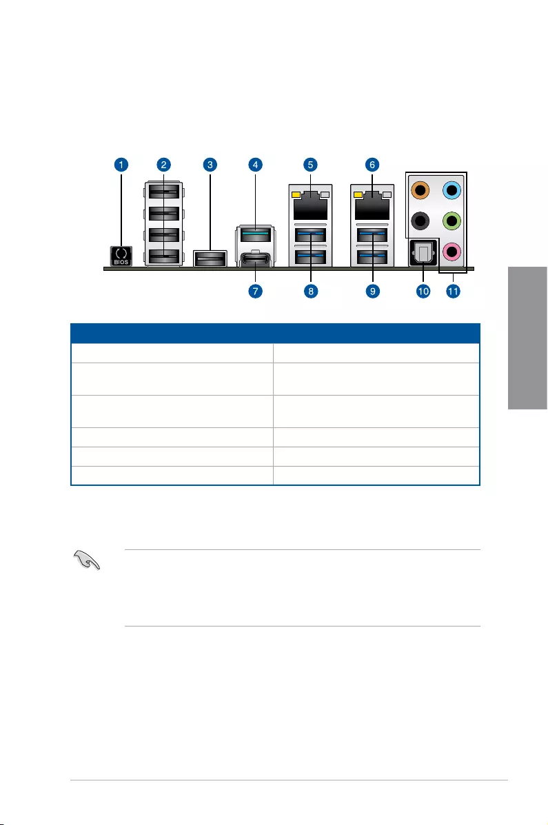
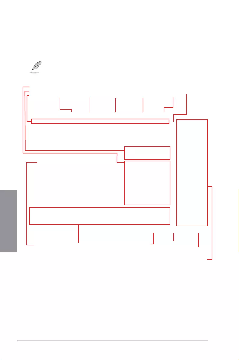
2.3.1 Rear I/O connection
*and **: Refer to the tables on the next page for LAN port LEDs, and audio port definitions.
Rear panel connectors
1. USB BIOS Flashback button 7. USB3.1Gen2Type-C™portEC1
2. USB 2.0 ports 9-12 (bottom port
supports USB BIOS Flashback)
8. USB3.1Gen1ports7and8
3. TUF Detective port (supports TUF
Detective 2 only)
9. USB 3.1 Gen 1 ports 5 and 6
4. USB3.1Gen2Type-AportE2 10. Optical S/PDIF Out port
5. Intel® LAN port (LAN2)* 11. Audio I/O ports**
6. Intel® LAN port (LAN1)*
• USB3.1Gen1/Gen2devicescanonlybeusedasdatastorageonly.
• Westronglyrecommendthatyouconnectyourdevicestoportswithmatchingdata
transfer rate. Please connect your USB 3.1 Gen 1 devices to USB 3.1 Gen 1 ports and
your USB 3.1 Gen 2 devices to USB 3.1 Gen 2 ports for faster and better performance
for your devices.
2-14 Chapter 2: Basic Installation
Chapter 2
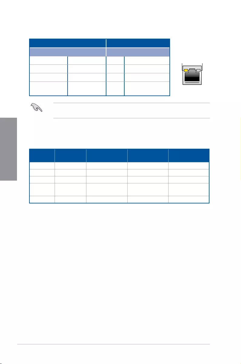
* LAN ports LED indications
ACT/LINK
LED SPEED
LED
LAN port
Activity Link LED Speed LED
Status Description Status Description
Off No link Off 10 Mbps connection
Orange Linked Orange 100 Mbps connection
Orange (Blinking) Data activity Green 1 Gbps connection
Orange (Blinking
then steady)
Readytowakeup
from S5 mode
You can disable the LAN controllers in BIOS. Due to hardware design, the LAN1 port’s
LEDsmaycontinuetoblinkevenwhendisabled.
** Audio 2, 4, 6 or 8-channel configuration
Port Headset
2-channel 4-channel 6-channel 8-channel
Light Blue Line In Line In Line In Side Speaker Out
Lime Line Out Front Speaker Out Front Speaker Out Front Speaker Out
Pink Mic In Mic In Mic In Mic In
Orange – – Center/Sub
woofer
Center/Sub
woofer
Black – RearSpeakerOut RearSpeakerOut RearSpeakerOut
ASUS TUF X299 MARK 1 2-15
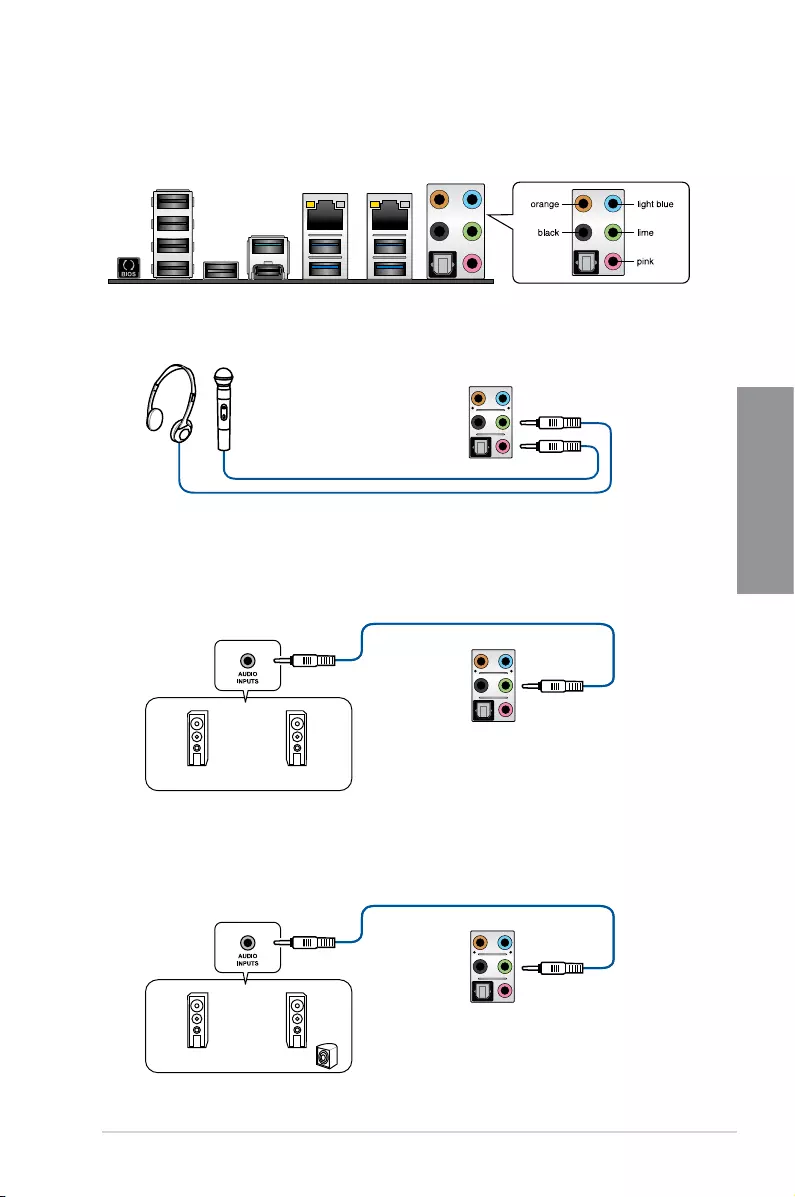
Chapter 2
2.3.2 Audio I/O connections
Audio I/O ports
Connect to Headphone and Mic
Connect to Stereo Speakers
Connect to 2 Speakers
2-16 Chapter 2: Basic Installation
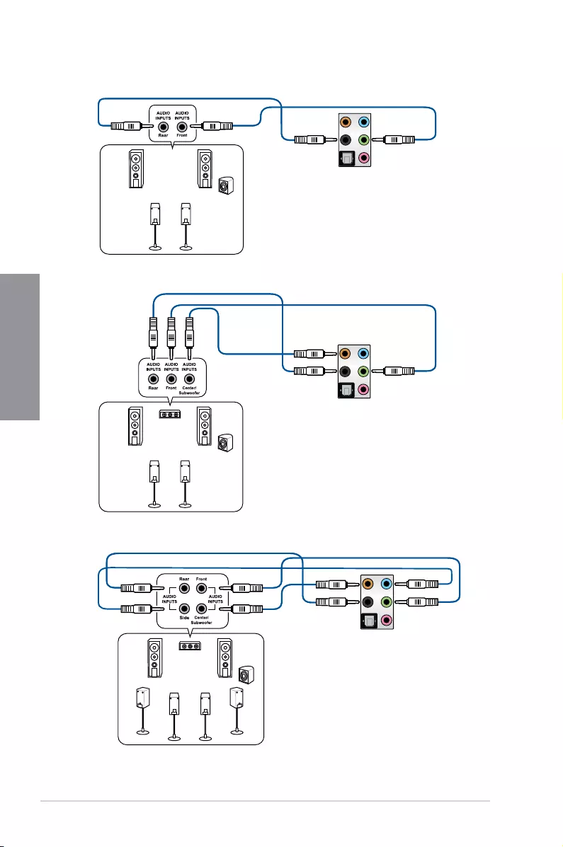
Chapter 2
Connect to 4 Speakers
Connect to 6 Speakers
Connect to 8 Speakers
ASUS TUF X299 MARK 1 2-17
Chapter 2
2.4 Starting up for the first time
1. After making all the connections, replace the system case cover.
2. Ensurethatallswitchesareoff.
3. Connect the power cord to the power connector at the back of the system chassis.
4. Connect the power cord to a power outlet that is equipped with a surge protector.
5. Turn on the devices in the following order:
a. Monitor
b. ExternalSCSIdevices(startingwiththelastdeviceonthechain)
c. System power
6. Afterapplyingpower,thesystempowerLEDonthesystemfrontpanelcaselightsup.
ForsystemswithATXpowersupplies,thesystemLEDlightsupwhenyoupressthe
ATX power button. If your monitor complies with the “green” standards or if it has a
“powerstandby”feature,themonitorLEDmaylightuporchangefromorangetogreen
afterthesystemLEDturnson.
Thesystemthenrunsthepower-onselftests(POST).Whilethetestsarerunning,the
BIOS beeps (refer to the BIOS beep codes table) or additional messages appear on
the screen. If you do not see anything within 30 seconds from the time you turned on
the power, the system may have failed a power-on test. Check the jumper settings and
connections or call your retailer for assistance.
BIOS Beep Description
One short beep
VGA detected
Quick boot set to disabled
No keyboard detected
One continuous beep followed by two
short beeps then a pause (repeated)
No memory detected
One continuous beep followed by three
short beeps
No VGA detected
One continuous beep followed by four
short beeps
Hardware component failure
7. At power on, hold down the <Delete> key to enter the BIOS Setup. Follow the
instructions in Chapter 3.
2.5 Turning off the computer
WhilethesystemisON,pressthepowerbuttonforlessthanfoursecondstoputthesystem
on sleep mode or soft-off mode, depending on the BIOS setting. Press the power switch
for more than four seconds to let the system enter the soft-off mode regardless of the BIOS
setting.

2-18 Chapter 2: Basic Installation
Chapter 2

ASUS TUF X299 MARK 1 3-1
Chapter 3
The new ASUS UEFI BIOS is a Unied Extensible Interface that complies with UEFI
architecture, offering a user-friendly interface that goes beyond the traditional keyboard-
only BIOS controls to enable a more exible and convenient mouse input. You can easily
navigate the new UEFI BIOS with the same smoothness as your operating system. The
term “BIOS” in this user manual refers to “UEFI BIOS” unless otherwise specied.
BIOS (Basic Input and Output System) stores system hardware settings such as storage
device conguration, overclocking settings, advanced power management, and boot
device conguration that are needed for system startup in the motherboard CMOS. In
normal circumstances, the default BIOS settings apply to most conditions to ensure
optimal performance. DO NOT change the default BIOS settings except in the following
circumstances:
• An error message appears on the screen during the system bootup and requests you
to run the BIOS Setup.
• You have installed a new system component that requires further BIOS settings or
update.
Inappropriate BIOS settings may result to instability or boot failure. We strongly
recommend that you change the BIOS settings only with the help of a trained service
personnel.
• When downloading or updating the BIOS le, rename it as X299TUF1.CAP for this
motherboard.
• BIOS settings and options may vary due to different BIOS release versions. Please
refer to the latest BIOS version for settings and options.
BIOS Setup
3
3.1 Knowing BIOS
Chapter 3: BIOS Setup

3-2 Chapter 3: BIOS Setup
Chapter 3
• The BIOS setup screens shown in this section are for reference purposes only, and
may not exactly match what you see on your screen.
• Ensure that a USB mouse is connected to your motherboard if you want to use the
mouse to control the BIOS setup program.
• If the system becomes unstable after changing any BIOS setting, load the default
settings to ensure system compatibility and stability. Select the Load Optimized
Defaults item under the Exit menu or press hotkey <F5>. See section 3.10 Exit Menu
for details.
• If the system fails to boot after changing any BIOS setting, try to clear the CMOS and
reset the motherboard to the default value. See section 1.1.6 Onboard buttons and
switches for information on how to erase the RTC RAM via the Clear CMOS button.
• The BIOS setup program does not support the Bluetooth devices.
Please visit ASUS website for the detailed BIOS content manual.
BIOS menu screen
The BIOS Setup program can be used under two modes: EZ Mode and Advanced Mode.
You can change modes from Setup Mode in Boot menu or by pressing the <F7> hotkey.
3.2 BIOS setup program
Use the BIOS Setup to update the BIOS or congure its parameters. The BIOS screen
include navigation keys and brief onscreen help to guide you in using the BIOS Setup
program.
Entering BIOS at startup
To enter BIOS Setup at startup, press <Delete> or <F2> during the Power-On Self Test
(POST). If you do not press <Delete> or <F2>, POST continues with its routines.
Entering BIOS Setup after POST
To enter BIOS Setup after POST:
• Press <Ctrl>+<Alt>+<Delete> simultaneously.
• Press the reset button on the system chassis.
• Press the power button to turn the system off then back on. Do this option only if you
failed to enter BIOS Setup using the rst two options.
After doing either of the three options, press <Delete> key to enter BIOS.
ASUS TUF X299 MARK 1 3-3
Chapter 3
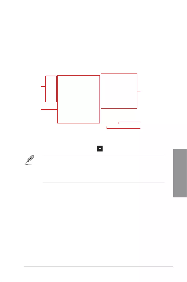
3.2.1 EZ Mode
The EZ Mode provides you an overview of the basic system information, and allows you to
select the display language, system performance, mode and boot device priority. To access
the Advanced Mode, select Advanced Mode or press the <F7> hotkey for the advanced
BIOS settings.
The default screen for entering the BIOS setup program can be changed. Refer to the
Setup Mode item in section Boot menu for details.
The boot device options vary depending on the devices you installed to the system.
Selects the display language
of the BIOS setup program
Displays the CPU/motherboard temperature,
CPU voltage output, CPU/chassis/power fan
speed, and SATA information
Displays the system properties of the selected mode.
Click < or > to switch EZ System Tuning modes
Loads optimized
default settings
Creates storage RAID and
configures system overclocking
Displays the CPU Fan’s speed. Click
the button to manually tune the fans
Enables or disables the SATA RAID mode
for Intel Rapid Storage Technology Saves the changes
and resets the system
Click to display boot devices
Selects the boot device priority
Click to go to Advanced mode
Search on the FAQ
3-4 Chapter 3: BIOS Setup
Chapter 3
3.2.2 Advanced Mode
The Advanced Mode provides advanced options for experienced end-users to congure
the BIOS settings. The gure below shows an example of the Advanced Mode. Refer to the
following sections for the detailed congurations.
To switch from EZ Mode to Advanced Mode, click Advanced Mode(F7) or press the <F7>
hotkey.
Menu items General help
Menu bar Language Hot Keys
Qfan Control(F6)
MyFavorite(F3) EZ Tuning Wizard(F11)
Scroll barPop-up Menu
Configuration fields
Last modified settings Go back to EZ Mode
Displays the CPU temperature,
CPU, and memory voltage output
Search on the FAQ

ASUS TUF X299 MARK 1 3-5
Chapter 3
Menu bar
The menu bar on top of the screen has the following main items:
My Favorites For saving the frequently-used system settings and conguration.
Main For changing the basic system conguration
Ai Tweaker For changing the overclocking settings
Advanced For changing the advanced system settings
Monitor For displaying the system temperature, power status, and changing the
fan settings.
Boot For changing the system boot conguration
Tool For conguring options for special functions
Exit For selecting the exit options and loading default settings
Menu items
The highlighted item on the menu bar displays the specic items for that menu. For example,
selecting Main shows the Main menu items.
The other items (My Favorites, Ai Tweaker, Advanced, Monitor, Boot, Tool, and Exit) on the
menu bar have their respective menu items.
Submenu items
A greater than sign (>) before each item on any menu screen means that the item has a
submenu. To display the submenu, select the item and press <Enter>.
Language
This button above the menu bar contains the languages that you can select for your BIOS.
Click this button to select the language that you want to display in your BIOS screen.
My Favorites (F3)
This button above the menu bar shows all BIOS items in a Tree Map setup. Select frequently-
used BIOS settings and save it to MyFavorites menu.
Refer to section 3.3 My Favorites for more information.
Q-Fan Control (F6)
This button above the menu bar displays the current settings of your fans. Use this button to
manually tweak the fans to your desired settings.
Refer to section 3.2.3 QFan Control for more information.
EZ Tuning Wizard (F11)
This button above the menu bar allows you to view and tweak the overclocking settings of
your system. It also allows you to change the motherboard’s SATA mode from AHCI to RAID
mode.
Refer to section 3.2.4 EZ Tuning Wizard for more information.

3-6 Chapter 3: BIOS Setup
Chapter 3
Search on FAQ
Move your mouse over this button to show a QR code, scan this QR code on your mobile
device to connect to the BIOS FAQ web page of the ASUS support website. You can also
scan the following QR code:
Hot keys
This button above the menu bar contains the navigation keys for the BIOS setup program.
Use the navigation keys to select items in the menu and change the settings.
Scroll bar
A scroll bar appears on the right side of a menu screen when there are items that do not t
on the screen. Press the Up/Down arrow keys or <Page Up> / <Page Down> keys to display
the other items on the screen.
General help
At the bottom of the menu screen is a brief description of the selected item. Use <F12> key
to capture the BIOS screen and save it to the removable storage device.
Configuration fields
These elds show the values for the menu items. If an item is user-congurable, you can
change the value of the eld opposite the item. You cannot select an item that is not
user-congurable.
A congurable eld is highlighted when selected. To change the value of a eld, select it and
press <Enter> to display a list of options.
Last Modified button
This button shows the items that you last modied and saved in BIOS Setup.
ASUS TUF X299 MARK 1 3-7
Chapter 3
3.2.3 QFan Control
The QFan Control allows you to set a fan prole or manually congure the operating speed of
your CPU and chassis fans.
Click to select a fan to be
configured Click to activate
PWM Mode
Click to undo the
changes
Click to apply the fan setting
Click to go back to main menu
Select a profile to apply to
your fans
Click to activate DC Mode
Select to manually configure
your fans

3-8 Chapter 3: BIOS Setup
Chapter 3
Speed points Select to manually
configure your fans
Configuring fans manually
Select Manual from the list of proles to manually congure your fans’ operating speed.
To congure your fans:
1. Select the fan that you want to congure and to view its current status.
2. Click and drag the speed points to adjust the fans’ operating speed.
3. Click Apply to save the changes then click Exit (ESC).

ASUS TUF X299 MARK 1 3-9
Chapter 3
3.2.4 EZ Tuning Wizard
EZ Tuning Wizard allows you to easily overclock your CPU and DRAM, computer usage, and
CPU fan to their best settings. You can also set RAID in your system using this feature.
RAID setup
OC Tuning
To start OC Tuning:
1. Press <F11> on your keyboard or click from the BIOS screen to open
EZ Tuning Wizard screen.
2. Click OC
then click Next.
3. Select a PC scenario Daily Computing or Gaming/Media Editing, then click Next.
OC setup

3-10 Chapter 3: BIOS Setup
Chapter 3
Creating RAID
To create RAID:
1. Press <F11> on your keyboard or click from the BIOS screen to open
EZ Tuning Wizard screen.
2. Click Yes
to enable RAID.
• Ensure that your HDDs have no existing RAID volumes.
• Ensure to connect your HDDs to Intel® SATA connectors.
3. Select the port that you want to set to [RAID] mode, PCIE or SATA, then click Next.
4. Select a Main Cooling System BOX cooler, Tower cooler, Water cooler, or I’m not
sure, then click Next.
5. After selecting the Main Cooling System, click Next then click Yes to start the OC
Tuning.

ASUS TUF X299 MARK 1 3-11
Chapter 3
5. After selecting the type of RAID, click Next then click Yes to continue the RAID setup.
6. After the RAID setup is done, click Yes to exit the setup then click OK to reset your
system.
You can only select Easy Backup (RAID 10) if you connect four (4) HDDs.
b. For Super Speed, click Next then select from Super Speed (RAID 0) or Super
Speed (RAID 5).
a. For Easy Backup, click Next then select from Easy Backup (RAID 1) or Easy
Backup (RAID 10).
4. Select the type of storage for your RAID, Easy Backup or Super Speed, then click
Next.

3-12 Chapter 3: BIOS Setup
Chapter 3
3.3 My Favorites
My Favorites is your personal space where you can easily save and access your favorite
BIOS items. My Favorites comes with several performance, power saving, and fast boot
related items by default. You can personalize this screen by adding or removing items.
ASUS TUF X299 MARK 1 3-13
Chapter 3
Adding items to My Favorites
To add BIOS items:
1. Press <F3> on your keyboard or click from the BIOS screen to open
Setup Tree Map screen.
2. On the Setup Tree Map screen, select the BIOS items that you want to save in My
Favorites screen.
3. Select an item from main menu panel, then click the submenu that you want to save as
favorite from the submenu panel and click or press <Enter> on your keyboard.
You cannot add the following items to My Favorite items:
• Items with submenu options
• User-managed items such as language and boot order
• Conguration items such as Memory SPD Information, system time and date.
4. Click Exit (ESC) or press <Esc> key to close Setup Tree Map screen.
5. Go to My Favorites menu to view the saved BIOS items.
Main menu panel
Submenu panel
Selected shortcut
items
Delete all favorite
items
Recover to default
favorite items

3-14 Chapter 3: BIOS Setup
Chapter 3
3.4 Main menu
The Main menu screen appears when you enter the Advanced Mode of the BIOS Setup
program. The Main menu provides you an overview of the basic system information, and
allows you to set the system date, time, language, and security settings.
Security
The Security menu items allow you to change the system security settings.
• If you have forgotten your BIOS password, erase the CMOS Real Time Clock (RTC)
RAM to clear the BIOS password. See section 1.1.6 Onboard buttons and switches
for information on how to erase the RTC RAM via the Clear CMOS button.
• The Administrator or User Password items on top of the screen show the default [Not
Installed]. After you set a password, these items show [Installed].
3.5 Ai Tweaker menu
The Extreme Tweaker menu items allow you to congure overclocking-related items.
Be cautious when changing the settings of the Extreme Tweaker menu items. Incorrect
eld values can cause the system to malfunction
The conguration options for this section vary depending on the CPU and DIMM model you
installed on the motherboard.
Ai Overclock Tuner
Allows you to select the CPU overclocking options to achieve the desired CPU internal
frequency. Conguration options:
[Auto] Loads the optimal settings for the system.
[Manual] Allows you to individually set overclocking parameters.
[X.M.P.] If you install memory modules supporting the eXtreme Memory Prole
(X.M.P.) Technology, choose this item to set the proles supported by your
memory modules for optimizing the system performance.
The [X.M.P.] conguration option appears only when you install memory modules
supporting the eXtreme Memory Prole(X.M.P.) Technology.
The following item appears only when you set the Ai Overclocking Tuner to [Manual].
BCLK Frequency
This item allows you to set the BCLK (base clock) frequency to enhance the system
performance. Use the <+> or <-> to adjust the value.
We recommend you to set the value based on the CPU specication, as high BCLK
frequencies may damage the CPU permanently.

ASUS TUF X299 MARK 1 3-15
Chapter 3
ASUS MultiCore Enhancement
[Auto] This item allows you to maximize the oveclocking performance optimized
by ASUS core ratio settings.
[Disabled] This item allows you to set to default core ratio settings.
CPU Core Ratio
This item allows you to set the CPU core ratios.
Conguration options: [Auto] [Sync All Cores] [By Core Usage]
BCLK Frequency : DRAM Frequency Ratio
[Auto] The BCLK frequency to DRAM frequency ratio will be set to the optimized
setting.
[100:133] The BCLK frequency to DRAM frequency ratio will be set to 100:133.
[100:100] The BCLK frequency to DRAM frequency ratio will be set to 100:100.
DRAM Frequency
This item allows you to set the memory operating frequency. The congurable options vary
with the BCLK (base clock) frequency setting. Select the auto mode to apply the optimized
setting.
Conguration options: [Auto] [DDR4-800MHz] — [DDR4-4266MHz]
TPU
This item allows you to automatically overclock the CPU and DRAM frequencies and voltage
for an enhanced system performance.
[Keep Current Settings] Keep the current settings without changing anything.
[TPU I] Applies air cooling overclocking conditions.
[TPU II] Applies water cooling overclocking conditions.
Ensure to use water cooling device before selecting [TPU II].
Internal CPU Power Management
The subitems in this menu allow you to set the CPU ratio and features.
Intel(R) SpeedStep(tm)
Allows the operating system to dynamically adjust the processor voltage and cores
frequency to decrease the average power consumption and decrease average heat
production.
Conguration options: [Auto] [Enabled] [Disabled]
Turbo Mode
Allows you to enable your processor cores to run faster than the base operating
frequency when it is below power, current and specication limit. Conguration options:
[Disabled] [Enabled]

3-16 Chapter 3: BIOS Setup
Chapter 3
3.6.3 System Agent (SA) Configuration
The items in this menu allow you to adjust the Link Speed for PEG Port and Multi-Monitor.
3.6.1 CPU Configuration
The items in this menu show the CPU-related information that the BIOS automatically
detects.
The items in this menu may vary based on the CPU installed.
Hyper-threading
This item allows a hyper-threading processor to appear as two logical processors, allowing
the operating system to schedule two threads or processors simultaneously.
Conguration options: [Disabled] [Enabled]
CPU Power Management Configuration
This item allows you to manage and congure the CPU’s power.
Intel(R) SpeedStep(tm)
This item allows more than two frequency to be supported.
Conguration options: [Auto] [Enabled] [Disabled]
Turbo Mode
This item allows you to automatically set the CPU cores to run faster than the base
operating frequency when it is below the operating power, current and temperature
specication limit.
Conguration options: [Enabled] [Disabled]
CPU C-States
This item allows you to set the power saving of the CPU states.
Conguration options: [Auto] [Disabled] [Enabled]
3.6 Advanced menu
The Advanced menu items allow you to change the settings for the CPU and other system
devices.
Be cautious when changing the settings of the Advanced menu items. Incorrect eld values
can cause the system to malfunction.
3.6.2 Platform Misc Configuration
The items in this menu allow you to change the ASPM for PCH and SA PCI Express.

ASUS TUF X299 MARK 1 3-17
Chapter 3
3.6.4 PCH Configuration
The items in this menu allow you to adjust the PCH PCI Express speed.
PCI Express Configuration
This item allows you to congure the PCI Express slots.
PCIe Speed
This item allows your system to automatically select the PCI Express port speed.
Conguration options: [Auto] [Gen1 (2.5 GT/s)] [Gen2 (5 GT/s)] [Gen3 (8 GT/s)]
3.6.5 PCH Storage Configuration
While entering Setup, the BIOS automatically detects the presence of SATA devices. The
SATA Port items show Not Present if no SATA device is installed to the corresponding SATA
port.
SATA Controller(s)
This item allows you to enable or disable the SATA Device.
Conguration options: [Disabled] [Enabled]
SATA Mode Selection
This item allows you to set the SATA conguration.
[AHCI] Set to [AHCI] when you want the SATA hard disk drives to
use the AHCI (Advanced Host Controller Interface). The
AHCI allows the onboard storage driver to enable advanced
Serial ATA features that increases storage performance on
random workloads by allowing the drive to internally optimize
the order of commands.
[Intel RST Premium
With Intel Optane
System Acceleration
(RAID)]
Set to [Intel RST Premium With Intel Optane System
Acceleration (RAID)] when you want to create a RAID
conguration from the SATA hard disk drives.
SMART Self Test
SMART (Self-Monitoring, Analysis and Reporting Technology) is a monitoring system that
shows a warning message during POST (Power-on Self Test) when an error occurs in the
hard disks.
Conguration options: [On] [Off]
SATA6G_1 — SATA6G_8
SATA6G_1 — SATA6G_8
This item allows you to enable or disable the selected SATA port.
Conguration options: [Disabled] [Enabled]
Hot Plug
These items appears only when the SATA Mode Selection is set to [AHCI] and allows
you to enable or disable SATA Hot Plug Support.
Conguration options: [Disabled] [Enabled]

3-18 Chapter 3: BIOS Setup
Chapter 3
HD Audio Controller
This item allows you to use the Azalia High Denition Audio Controller.
Conguration options: [Disabled] [Enabled]
PCIEX16_3 & PCIEX4_1 Switch Function
[Auto] If a device is detected in PCIEX16_3, PCIEX16_3 will be enabled and
PCIEX4_1 will be disabled.
[X4_1 mode] Enable PCIEX4_1 to X4 mode and PCIEX16_3 will be disabled.
PCIEX4_2 & SATA6G_5~8 Switch Function
[Auto (X2 mode)] If a device is detected in PCIEX4_2, PCIEX4_2 will be enabled and
SATA6G_78 will be disabled
[X4 mode] Enable PCIEX4_2 to X4 mode and SATA6G_5~8 will be disabled.
USB Type C Power Switch
[Auto] The system will automatically detect your USB Type C devices and provide
suitable power if needed.
[Enabled] The USB Type C port will always provide power to your devices.
RGB LED lighting
When system is in working state
This item allows you to turn the RGB LED lighting on or off when the system is in the
working state.
Conguration options: [On] [Off]
When system is in sleep, hibernate or soft off states
This item allows you to turn the RGB LED lighting on or off when the system is in the
sleep, hibernate or soft off states.
Conguration options: [On] [Off]
Intel LAN Controller
This item allows you to enable or disable the Intel LAN controller.
Conguration options: [Disabled] [Enabled]
3.6.7 Onboard Devices Configuration
The items in this menu allow you to switch between PCIe Lanes and congure onboard
devices.
3.6.6 CPU Storage Configuration
The items in this menu allow you to congure CPU storage congurations.
• This menu will appear only when an Intel® Core™ X-series Processors (6-core or
above) is installed.
• Due to CPU behavior, CPU RAID functions with Intel® CPU RSTe only supports Intel®
Core™ X-series Processors (6-core or above) and Intel® SSD modules.

ASUS TUF X299 MARK 1 3-19
Chapter 3
3.6.8 APM Configuration
The items in this menu allow you to set system wake and sleep settings.
ErP Ready [Disabled]
This item allows you to switch off some power at S4+S5 or S5 to get the system ready for
ErP requirement. When set to [Enabled], all other PME options are switched off.
Conguration options: [Disabled] [Enable(S4+S5)] [Enable(S5)]
3.6.9 Network Stack Configuration
The items in this menu allow you to congure Ipv4 / Ipv6 PXE support.
3.6.10 HDD/SSD SMART Information
This menu displays the SMART information of the connected devices.
NVM Express devices do not support SMART information.
3.6.11 USB Configuration
The items in this menu allow you to change the USB-related features.
The Mass Storage Devices item shows the auto-detected values. If no USB device is
detected, the item shows None.
USB Single Port Control
This item allows you to enable or disable the individual USB ports.
Refer to section 1.1.2 Motherboard layout for the location of the USB ports.
3.6.12 Thunderbolt(TM) Configuration
The items in this menu allow you to congure Thunderbolt settings.
TBT Root port Selector
This item allows you to select the thunder root port.
Conguration options: [Thunderbolt Disabled] [PCIE16_1] [PCIE16_2] [PCIE4_2]

3-20 Chapter 3: BIOS Setup
Chapter 3
3.7 Monitor menu
The Monitor menu displays the system temperature/power status, and allows you to change
the fan settings.
Q-fan Configuration
Q-fan Tuning
Click this item to automatically detect the lowest speed and congure the minimum
duty cycle for each fan.
AIO PUMP / W_PUMP+ Control
[Disabled] Disable the Water Pump control feature.
[Auto] Detects the type of water pump installed and automatically switches
the control modes.
[DC mode] Enable the Water Pump control in DC mode for 3-pin chassis fan.
[PWM mode] Enable the Water Pump control in PWM mode for 4-pin chassis fan.
3.8 Boot menu
The Boot menu items allow you to change the system boot options.
Fast Boot
[Disabled] Allows your system to go back to its normal boot speed.
[Enabled] Allows your system to accelerate the boot speed.
The following items appear only when you set the Fast Boot to [Enabled].
Next Boot after AC Power Loss
[Normal Boot] Returns to normal boot on the next boot after an AC power loss.
[Fast Boot] Accelerates the boot speed on the next boot after an AC power loss.
3.6.13 PCH-FW Configuration
This item allows you to congure the rmware TPM.

ASUS TUF X299 MARK 1 3-21
Chapter 3
Boot Configuration
Setup Mode
[Advanced Mode] This item allows you to go to Advanced Mode of the
BIOS after POST.
[EZ Mode] This item allows you to go to EZ Mode of the BIOS after POST.
CSM (Compatibility Support Module)
This item allows you to congure the CSM (Compatibility Support Module) items to fully
support the various VGA, bootable devices and add-on devices for better compatibility.
Launch CSM
[Auto] The system automatically detects the bootable devices and the add-
on devices.
[Enabled] For better compatibility, enable the CSM to fully support the non-UEFI
driver add-on devices or the Windows® UEFI mode.
[Disabled] Disable the CSM to fully support the non-UEFI driver add-on devices
or the Windows® UEFI mode.
The following items appear only when you set the Launch CSM to [Enabled].
Boot Devices Control
This item allows you to select the type of devices that you want to boot.
Conguration options: [UEFI and Legacy OPROM] [Legacy OPROM only]
[UEFI only]
Boot from Network Devices
This item allows you to select the type of network devices that you want to
launch.
Conguration options: [Ignore] [Legacy only] [UEFI driver rst]
Boot from Storage Devices
This item allows you to select the type of storage devices that you want to
launch.
Conguration options: [Ignore] [Legacy only] [UEFI driver rst]
Boot from PCI-E/PCI Expansion Devices
This item allows you to select the type of PCI-E/PCI expansion devices that
you want to launch.
Conguration options: [Legacy only] [UEFI driver rst]
Secure Boot
This item allows you to congure the Windows® Secure Boot settings and manage its keys to
protect the system from unauthorized access and malwares during POST.

3-22 Chapter 3: BIOS Setup
Chapter 3
Boot Option Priorities
These items specify the boot device priority sequence from the available devices. The
number of device items that appears on the screen depends on the number of devices
installed in the system.
• To access Windows® OS in Safe Mode, press <F8> after POST (Windows® 8 not
supported).
• To select the boot device during system startup, press <F8> when the ASUS Logo
appears.
Boot Override
These items displays the available devices. The number of device items that appears on
the screen depends on the number of devices installed in the system. Click an item to start
booting from the selected device.
3.9 Tool menu
The Tool menu items allow you to congure options for special functions. Select an item then
press <Enter> to display the submenu.
Setup Animator
This item allows you to enable or disable the Setup animator.
Conguration options: [Disabled] [Enabled]
3.9.1 ASUS EZ Flash 3 Utility
This item allows you to run ASUS EZ Flash 3. When you press <Enter>, a conrmation
message appears. Use the left/right arrow key to select between [Yes] or [No], then press
<Enter> to conrm your choice.
For more details, refer to section 3.11.2 ASUS EZ Flash 3.

ASUS TUF X299 MARK 1 3-23
Chapter 3
3.9.2 Secure Erase
SSD speeds may lower over time as with any storage medium due to data processing.
Secure Erase completely and safely cleans your SSD, restoring it to factory performance
levels.
Secure Erase is only available in AHCI mode. Ensure to set the SATA mode to AHCI. Click
Advanced > PCH Storage Configuration > SATA Mode Selection > AHCI.
To launch Secure Erase, click Tool > Secure Erase on the Advanced mode menu.
Check the ASUS support site for a full list of SSDs tested with Secure Erase. The drive may
become unstable if you run Secure Erase on an incompatible SSD.
• The time to erase the contents of your SSD may take a while depending on its size.
Do not turn off the system during the process.
• Secure Erase is only supported on Intel SATA port. For more information about Intel
SATA ports, refer to section 1.1.2 Motherboard layout of this manual.
Status definition:
• Frozen. The frozen state is the result of a BIOS protective measure. The BIOS
guards drives that do not have password protection by freezing them prior to booting.
If the drive is frozen, a power off or hard reset of your PC must be performed to
proceed with the Secure Erase.
• Locked. SSDs might be locked if the Secure Erase process is either incomplete
or was stopped. This may be due to a third party software that uses a different
password dened by ASUS. You have to unlock the SSD in the software before
proceeding with Secure Erase.
Displays the
available SSDs

3-24 Chapter 3: BIOS Setup
Chapter 3
3.9.3 ASUS Overclocking Profile
This item allows you to store or load multiple BIOS settings.
Load from Profile
This item allows you to load the previous BIOS settings saved in the BIOS Flash. Key in the
prole number that saved your BIOS settings, press <Enter>, and then select Yes.
• DO NOT shut down or reset the system while updating the BIOS to prevent the
system boot failure!
• We recommend that you update the BIOS le only coming from the same memory/
CPU conguration and BIOS version.
Profile Name
This item allows you to key in a prole name.
Save to Profile
This item allows you to save the current BIOS settings to the BIOS Flash, and create a
prole. Key in a prole number from one to eight, press <Enter>, and then select Yes.
Load/Save Profile from/to USB Drive
This item allows you to load or save prole from your USB drive, load and save prole to your
USB drive.
3.9.4 ASUS SPD Information
This item allows you to view the DRAM SPD information.
3.9.5 Graphics Card Information
This item displays the information about the graphics card installed in your system.
GPU Post
This item displays the information and recommended conguration for the PCIE slots that the
graphics card is installed in your system.
This feature is only supported on selected ASUS graphics cards.
Bus Interface
This item allows you to select the bus interface.
Conguration options: [PCIEX16_1] [PCIEX16_2] [PCIEX16_3] [PCIEX16_4]

ASUS TUF X299 MARK 1 3-25
Chapter 3
3.10 Exit menu
The Exit menu items allow you to load the optimal default values for the BIOS items, and
save or discard your changes to the BIOS items. You can access the EZ Mode from the Exit
menu.
Load Optimized Defaults
This option allows you to load the default values for each of the parameters on the Setup
menus. When you select this option or if you press <F5>, a conrmation window appears.
Select OK to load the default values.
Save Changes & Reset
Once you are nished making your selections, choose this option from the Exit menu to
ensure the values you selected are saved. When you select this option or if you press <F10>,
a conrmation window appears. Select OK to save changes and exit.
Discard Changes & Exit
This option allows you to exit the Setup program without saving your changes. When you
select this option or if you press <Esc>, a conrmation window appears. Select Yes to
discard changes and exit.
Launch EFI Shell from filesystem device
This item allows you to attempt to launch the EFI Shell application (shellx64.e) from one of
the available lesystem devices.

3-26 Chapter 3: BIOS Setup
Chapter 3
3.11 Updating BIOS
The ASUS website publishes the latest BIOS versions to provide enhancements on system
stability, compatibility,and performance. However, BIOS updating is potentially risky. If
there is no problem using the current version of BIOS, DO NOT manually update the BIOS.
Inappropriate BIOS updating may result to system’s failure to boot. Carefully follow the
instructions in this chapter to update your BIOS when necessary.
Visit http://www.asus.com to download the latest BIOS le for this motherboard.
The following utilities allow you to manage and update the motherboard BIOS setup program.
1. EZ Update: Updates the BIOS in Windows® environment.
2. ASUS EZ Flash 3: Updates the BIOS using a USB ash drive or through the Internet.
3. ASUS CrashFree BIOS 3: Restores the BIOS using the motherboard support DVD or a
USB ash drive when the BIOS le fails or gets corrupted.
3.11.1 EZ Update
The EZ Update is a utility that allows you to update the motherboard BIOS in Windows®
environment.
• EZ Update requires an Internet connection either through a network or an ISP
(Internet Service Provider).
• This utility is available in the support DVD that comes with the motherboard package.

ASUS TUF X299 MARK 1 3-27
Chapter 3
3.11.2 ASUS EZ Flash 3
ASUS EZ Flash 3 allows you to download and update to the latest BIOS through the Internet
without having to use a bootable oppy disk or an OS-based utility.
Updating through the Internet varies per region and Internet conditions. Check your local
Internet connection before updating through the Internet.
To update the BIOS by USB:
1. Enter the Advanced Mode of the BIOS setup program. Go to the Tool menu to select
ASUS EZ Flash Utility and press <Enter>.
2. Insert the USB ash disk that contains the latest BIOS le to the USB port.
3. Select by USB.
4. Press <Tab> to switch to the Drive eld.
5. Press the Up/Down arrow keys to nd the USB ash disk that contains the latest BIOS,
and then press <Enter>.
6. Press <Tab> to switch to the Folder Info eld.
7. Press the Up/Down arrow keys to nd the BIOS le, and then press <Enter> to perform
the BIOS update process. Reboot the system when the update process is done.

3-28 Chapter 3: BIOS Setup
Chapter 3
• This function can support devices such as a USB ash disk with FAT 32/16 format and
single partition only.
• DO NOT shut down or reset the system while updating the BIOS to prevent system
boot failure!
Ensure to load the BIOS default settings to ensure system compatibility and stability. Select
the Load Optimized Defaults item under the Exit menu. See section 3.10 Exit Menu for
details.
To update the BIOS by Internet:
1. Enter the Advanced Mode of the BIOS setup program. Go to the Tool menu to select
ASUS EZ Flash Utility and press <Enter>.
2. Select by Internet.
3. Press the Left/Right arrow keys to select an Internet connection method, and then
press <Enter>.
Ensure to load the BIOS default settings to ensure system compatibility and stability. Select
the Load Optimized Defaults item under the Exit menu. See section 3.10 Exit Menu for
details.
4. Follow the onscreen instructions to complete the update.
5. Reboot the system when the update process is done.

ASUS TUF X299 MARK 1 3-29
Chapter 3
3.11.3 ASUS CrashFree BIOS 3
The ASUS CrashFree BIOS 3 utility is an auto recovery tool that allows you to restore the
BIOS le when it fails or gets corrupted during the updating process. You can restore a
corrupted BIOS le using the motherboard support DVD or a USB ash drive that contains
the BIOS le.
The BIOS le in the motherboard support DVD may be older than the BIOS le published
on the ASUS ofcial website. If you want to use the newer BIOS le, download the le at
https://www.asus.com/support/ and save it to a USB ash drive.
Recovering the BIOS
To recover the BIOS:
1. Turn on the system.
2. Insert the motherboard support DVD to the optical drive, or the USB ash drive
containing the BIOS le to the USB port.
3. The utility automatically checks the devices for the BIOS le. When found, the utility
reads the BIOS le and enters ASUS EZ Flash 3 automatically.
4. The system requires you to enter BIOS Setup to recover the BIOS setting. To ensure
system compatibility and stability, we recommend that you press <F5> to load default
BIOS values.
DO NOT shut down or reset the system while updating the BIOS! Doing so can cause
system boot failure!

3-30 Chapter 3: BIOS Setup
Chapter 3

ASUS TUF X299 MARK 1 4-1
Chapter 4
4
RAID Support
Chapter 4: RAID Support
4.1 RAID configurations
The motherboard supports Intel® Rapid Storage Technology with RAID 0, RAID 1, RAID 5,
and RAID 10 solution.
If you want to install a Windows® operating system to a hard disk drive included in a RAID
set, you have to create a RAID driver disk and load the RAID driver during OS installation.
Refer to section 4.2 Creating a RAID driver disk for details.
4.1.1 RAID definitions
RAID 0 (Data striping) optimizes two identical hard disk drives to read and write data in
parallel, interleaved stacks. Two hard disks perform the same work as a single drive but at a
sustained data transfer rate, double that of a single disk alone, thus improving data access
and storage. Use of two new identical hard disk drives is required for this setup.
RAID 1 (Data mirroring) copies and maintains an identical image of data from one drive to
a second drive. If one drive fails, the disk array management software directs all applications
to the surviving drive as it contains a complete copy of the data in the other drive. This RAID
conguration provides data protection and increases fault tolerance to the entire system. Use
two new drives or use an existing drive and a new drive for this setup. The new drive must be
of the same size or larger than the existing drive.
RAID 5 strips both data and parity information across three or more hard disk drives. Among
the advantages of RAID 5 conguration include better HDD performance, fault tolerance, and
higher storage capacity. The RAID 5 conguration is best suited for transaction processing,
relational database applications, enterprise resource planning, and other business systems.
Use a minimum of three identical hard disk drives for this setup.
RAID 10 is data striping and data mirroring combined without parity (redundancy data) having
to be calculated and written. With the RAID 10 conguration you get all the benets of both
RAID 0 and RAID 1 congurations. Use four new hard disk drives or use an existing drive
and three new drives for this setup.

4-2 Chapter 4: RAID Support
Chapter 4
4.1.2 Installing storage devices
The motherboard supports Serial ATA hard disk drives and PCIE SSD storage devices. For
optimal performance, install identical drives of the same model and capacity when creating a
disk array.
Refer to Chapter 2 for details on installing storage devices to your motherboard.
4.1.3 Intel® Rapid Storage Technology in UEFI BIOS
To enter the Intel® Rapid Storage Technology in UEFI BIOS:
1. Enter the BIOS Setup during POST.
2. Go to the Advanced menu > PCH Storage Configuration, then press <Enter>.
3. Set the SATA Mode Selection item to [Intel RST Premium With Intel Optane System
Acceleration (RAID)].
If you are using PCIE storage devices, ensure to enable all the PCIE Storage RAID
Support items.
4. Go to the Boot menu > CSM (Compatibility Support Module) > Launch CSM, then
set the item to [Disabled].
5. Save your changes and exit the BIOS Setup, then enter the BIOS Setup again.
6. Go to the Advanced menu > Intel(R) Rapid Storage Technology, then press <Enter>
to display the Intel® Rapid Storage Technology menu.
Refer to Chapter 3 for details on entering and navigating through the BIOS Setup.
Due to chipset limitation, when SATA ports are set to RAID mode, all SATA ports run at
RAID mode together.

ASUS TUF X299 MARK 1 4-3
Chapter 4
Creating a RAID set
To create a RAID set:
1. From the Intel® Rapid Storage Technology menu, select Create RAID Volume and
press <Enter>. The following screen appears:
2. When the Name item is selected, enter a name for the RAID set and press <Enter>.
3. When the RAID Level item is selected, press <Enter> to select the RAID level to
create, and then press <Enter>.
4. Under Select Disks, press <Enter> and select X for the disks you want to include in
the RAID set.

4-4 Chapter 4: RAID Support
Chapter 4
5. When the Strip Size item is selected, press <Enter> to select strip size for the RAID
array (for RAID 0, 10 and 5 only), and then press <Enter>. The available strip size
values range from 4 KB to 128 KB. The following are typical values:
— RAID 0: 128 KB
— RAID 10: 64 KB
— RAID 5: 64 KB
We recommend a lower strip size for server systems, and a higher strip size for multimedia
computer systems used mainly for audio and video editing.
6. When the Capacity (MB) item is selected, enter the RAID volume capacity that you
want and press <Enter>. The default value indicates the maximum allowed capacity.
7. When the Create Volume item is selected, press <Enter> to create the RAID volume
and return to the Intel® Rapid Storage Technology menu.

ASUS TUF X299 MARK 1 4-5
Chapter 4
Deleting a RAID set
Be cautious when deleting a RAID set. You will lose all data on the hard disk drives when
you delete a RAID set.
To delete a RAID set:
1. From the Intel® Rapid Storage Technology menu, select the RAID volume you want to
delete and press <Enter>. The following screen appears:
2. When the Delete item is selected, press <Enter>, then select Yes to delete the RAID
volume and return to the Intel® Rapid Storage Technology menu, or select No to
cancel.

4-6 Chapter 4: RAID Support
Chapter 4
4.1.4 Intel® Virtual Raid on CPU in UEFI BIOS
This feature requires a KEY module to enable CPU RAID functions with Intel® CPU RSTe.
• The KEY module is purchased separately.
• The HYPER M.2 X16 Card is purchased separately.
• Due to CPU behavior, CPU RAID functions with Intel® CPU RSTe only supports Intel®
Core™ X-series Processors (6-core or above) and Intel® SSD modules.
• Refer to section 1.1.9 Internal connectors for the location of the VROC_HW_KEY
connector.
Due to hardware design, your motherboard does not support CPU RAID congurations as
OS drives.
To enter the Intel® Virtual Raid on CPU in UEFI BIOS:
1. Enter the BIOS Setup during POST.
2. Go to the Boot menu > CSM (Compatibility Support Module) > Launch CSM, then
set the item to [Disabled].
3. Go to the Advanced menu > CPU Storage Configuration, then set the PCIE slot(s)
that you have installed the Hyper M.2 X16 Card(s) or PCIE X4 SSD Card(s) to Hyper
M.2 X16 or PCIE X4 SSD Card correspondingly.
4. Save your changes and exit the BIOS Setup, then enter the BIOS Setup again.
5. Go to the Advanced menu > Intel(R) Virtual Raid on CPU > All Intel VMD
Controllers, then press <Enter> to display the Intel® Virtual Raid on CPU menu.
Refer to Chapter 3 for details on entering and navigating through the BIOS Setup.

ASUS TUF X299 MARK 1 4-7
Chapter 4
Creating a RAID set
To create a RAID set:
1. From the Intel® Virtual Raid on CPU menu, select Create RAID Volume and press
<Enter>. The following screen appears:
2. When the Name item is selected, enter a name for the RAID set and press <Enter>.
3. When the RAID Level item is selected, press <Enter> to select the RAID level to
create, and then press <Enter>.
4. When the Enable RAID spanned over VMD Controllers item is selected, press
<Enter> and select X to enable this function.
5. Under Select Disks, press <Enter> and select X for the disks you want to include in the
RAID set.

4-8 Chapter 4: RAID Support
Chapter 4
6. When the Strip Size item is selected, press <Enter> to select strip size for the RAID
array (for RAID 0, 10 and 5 only), and then press <Enter>. The available strip size
values range from 4 KB to 128 KB. The following are typical values:
— RAID 0: 128 KB
— RAID 10: 64 KB
— RAID 5: 64 KB
We recommend a lower strip size for server systems, and a higher strip size for multimedia
computer systems used mainly for audio and video editing.
7. When the Capacity (MB) item is selected, enter the RAID volume capacity that you
want and press <Enter>. The default value indicates the maximum allowed capacity.
8. When the Create Volume item is selected, press <Enter> to create the RAID volume
and return to the Intel® Rapid Storage Technology menu.

ASUS TUF X299 MARK 1 4-9
Chapter 4
Deleting a RAID set
Be cautious when deleting a RAID set. You will lose all data on the hard disk drives when
you delete a RAID set.
To delete a RAID set:
1. From the Intel® Virtual Raid on CPU menu, select the RAID volume you want to delete
and press <Enter>. The following screen appears:
2. When the Delete item is selected, press <Enter>, then select Yes to delete the RAID
volume and return to the Intel® Virtual Raid on CPU menu, or select No to cancel.

4-10 Chapter 4: RAID Support
Chapter 4
Installing the RAID controller driver during Windows® 10 OS installation
After creating the RAID sets, you are now ready to install an operating system to the
independent drives or bootable array. This part provides the instructions on how to install the
RAID controller drivers during OS installation.
To install the RAID controller driver when installing Windows® 10 OS:
1. Boot the computer using the Windows® 10 OS installation disc. Follow the screen
instructions to start installing Windows® 10.
2. When prompted to choose a type of installation, click Custom: Install Windows only
(advanced).
3. Click Load Driver.

ASUS TUF X299 MARK 1 4-11
Chapter 4
4. A message appears, reminding you to insert the installation media containing the driver
of the RAID controller driver. If you have only one optical drive installed in your system,
eject the Windows OS installation disc and replace with the motherboard Support DVD
into the optical drive. Click Browse to continue.
5. Locate the driver in the corresponding folder of the Support DVD then click OK to
continue.
6. Select the RAID controller driver you need from the list and click Next.
7. When the system nishes loading the RAID driver, replace the motherboard Support
DVD with the Windows Server installation disc. Select the drive to install Windows and
click Next.
8. Setup then proceeds with the OS installation. Follow screen instructions to continue.
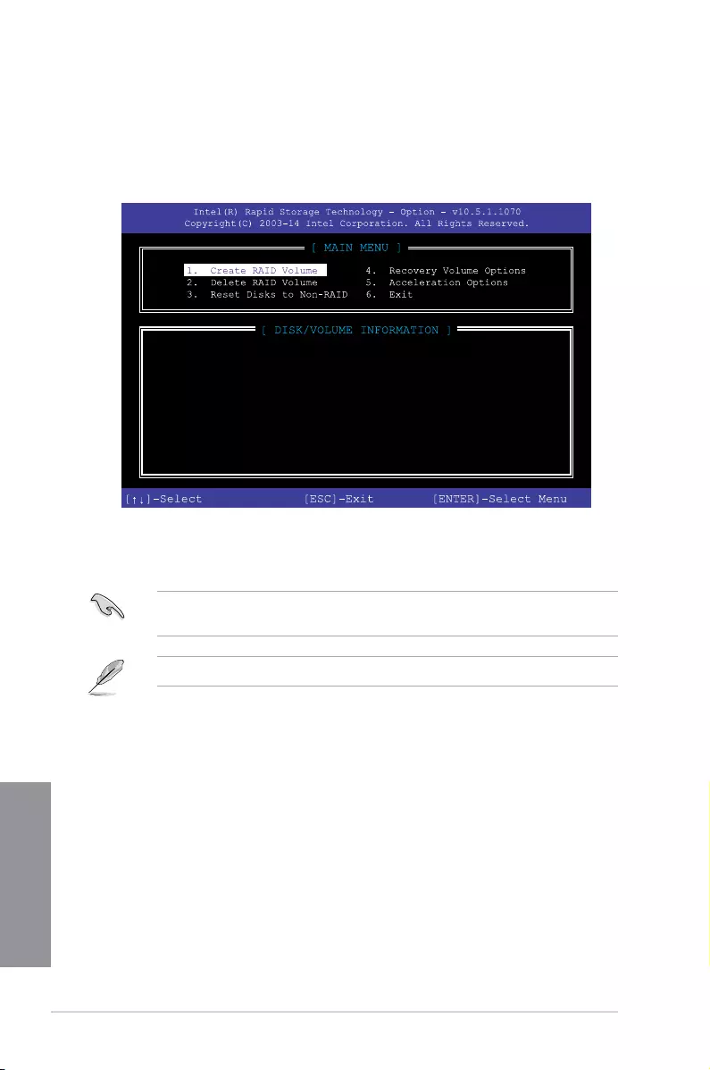
4-12 Chapter 4: RAID Support
Chapter 4
4.1.5 Intel® Rapid Storage Technology Option ROM utility
To enter the Intel® Rapid Storage Technology Option ROM utility:
1. Turn on the system.
2. During POST, press <Ctrl> + <I> to display the utility main menu.
The navigation keys at the bottom of the screen allow you to move through the menus
and select the menu options.
The RAID BIOS setup screens shown in this section are for reference only and may not
exactly match the items on your screen.
The utility supports maximum four hard disk drives for RAID conguration.
RAID Volumes:
None defined.
Physical Devices:
Port Device Model Serial # Size Type/Status(Vol ID)
0 ST3160812AS 9LS0HJA4 149.0GB Non-RAID Disk
1 ST3160812AS 9LS0F4HL 149.0GB Non-RAID Disk
2 ST3160812AS 3LS0JYL8 149.0GB Non-RAID Disk
3 ST3160812AS 9LS0BJ5H 149.0GB Non-RAID Disk

ASUS TUF X299 MARK 1 4-13
Chapter 4
Creating a RAID set
To create a RAID set:
1. From the utility main menu, select 1. Create RAID Volume and press <Enter>. The
following screen appears:
2. Enter a name for the RAID set and press <Enter>.
3. When the RAID Level item is selected, press the up/down arrow key to select a RAID
level to create, and then press <Enter>.
4. When the Disks item is selected, press <Enter> to select the hard disk drives you want
to include in the RAID set. The SELECT DISKS screen appears:
Enter a unique volume name that has no special characters
and is 16 characters or less.
[HELP]
Name: Volume 0
RAID Level: aaaaaaaaaaaaaaa
Disks: dssdsdsds
Strip Size:aaaaaaaaaaaaaaaa
Capacity:aaaaaaaaaaaaaa
Sync:aaaaaaaaaa
Create volume
[SELECT DISKS]
Port Device Model Serial # Size Status
0 ST3160812AS 9LS0HJA4 149.0GB Non-RAID Disk
1 ST3160812AS 9LS0F4HL 149.0GB Non-RAID Disk
2 ST3160812AS 3LS0JYL8 149.0GB Non-RAID Disk
3 ST3160812AS 9LS0BJ5H 149.0GB Non-RAID Disk
Select 2 to 6 to use in creating the volume.
[↑↓]-Prev/Next [SPACE]-SelectDisk [ENTER]-Done

4-14 Chapter 4: RAID Support
Chapter 4
5. Use the up/down arrow key to select a drive, and then press <Space> to select. A
small triangle marks the selected drive. Press <Enter> after completing your selection.
6. Use the up/down arrow key to select the strip size for the RAID array (for RAID 0, 10
and 5 only), and then press <Enter>. The available strip size values range from 4 KB to
128 KB. The following are typical values:
— RAID 0: 128 KB
— RAID 10: 64 KB
— RAID 5: 64 KB
We recommend a lower strip size for server systems, and a higher strip size for multimedia
computer systems used mainly for audio and video editing.
7. When the Capacity item is selected, enter the RAID volume capacity that you want
and press <Enter>. The default value indicates the maximum allowed capacity.
8. When the Create Volume item is selected, press <Enter>. The following warning
message appears:
9. Press <Y> to create the RAID volume and return to the main menu, or <N> to go back
to the CREATE VOLUME menu.
WARNING: ALL DATA ON SELECTED DISKS WILL BE LOST.
Are you sure you want to create this volume? (Y/N)

ASUS TUF X299 MARK 1 4-15
Chapter 4
Deleting a RAID set
Be cautious when deleting a RAID set. You will lose all data on the hard disk drives when
you delete a RAID set.
To delete a RAID set:
1. From the utility main menu, select 2. Delete RAID Volume and press <Enter>. The
following screen appears:
2. Use the up/down arrow key to select the RAID set you want to delete, and then press
<Delete>. The following warning message appears:
3. Press <Y> to delete the RAID set and return to the utility main menu, or press <N> to
return to the DELETE VOLUME menu.
Deleting a volume will reset the disks to non-RAID.
WARNING: ALL DISK DATA WILL BE DELETED.
(This does not apply to Recovery volumes)
[HELP]
[DELETE VOLUME MENU]
Name Level Drives Capacity Status Bootable
Volume0 RAID0 (Stripe) 2 298.0GB Normal Yes
[↑↓]-Select [ESC]-Previous Menu [DEL]-Delete Volume
ALL DATA IN THE VOLUME WILL BE LOST!
(This does not apply to Recovery volumes)
Are you sure you want to delete “Volume0”? (Y/N):
[DELETE VOLUME VERIFICATION]

4-16 Chapter 4: RAID Support
Chapter 4
Exiting the Intel® Rapid Storage Technology Option ROM utility
To exit the utility:
1. From the utility main menu, select 6. Exit, then press <Enter>. The following warning
message appears:
2. Press <Y> to exit or press <N> to return to the utility main menu.
Are you sure you want to exit? (Y/N):
4.2 Creating a RAID driver disk
4.2.1 Creating a RAID driver disk in Windows®
To install the RAID driver for Windows® OS:
1. During the OS installation, click Load Driver to allow you to select the installation
media containing the RAID driver.
2. Insert the USB ash drive with RAID driver into the USB port or the support DVD into
the optical drive, and then click Browse.
3. Click the name of the device you’ve inserted, go to Drivers > RAID, and then select
the RAID driver for the corresponding OS version. Click OK.
4. Follow the succeeding screen instructions to complete the installation.
Before loading the RAID driver from a USB ash drive, you have to use another computer
to copy the RAID driver from the support DVD to the USB ash drive.
To set up a Windows® UEFI operating system under RAID mode, ensure to load the UEFI
driver for your optical drive.

ASUS TUF X299 MARK 1 A-1
Appendix
Appendix
Notices
Federal Communications Commission Statement
This device complies with Part 15 of the FCC Rules. Operation is subject to the following two
conditions:
• This device may not cause harmful interference.
• This device must accept any interference received including interference that may cause
undesired operation.
This equipment has been tested and found to comply with the limits for a Class B digital
device, pursuant to Part 15 of the FCC Rules. These limits are designed to provide
reasonable protection against harmful interference in a residential installation. This
equipment generates, uses and can radiate radio frequency energy and, if not installed
and used in accordance with manufacturer’s instructions, may cause harmful interference
to radio communications. However, there is no guarantee that interference will not occur
in a particular installation. If this equipment does cause harmful interference to radio or
television reception, which can be determined by turning the equipment off and on, the user
is encouraged to try to correct the interference by one or more of the following measures:
• Reorient or relocate the receiving antenna.
• Increase the separation between the equipment and receiver.
• Connect the equipment to an outlet on a circuit different from that to which the receiver
is connected.
• Consult the dealer or an experienced radio/TV technician for help.
The use of shielded cables for connection of the monitor to the graphics card is required
toassurecompliancewithFCCregulations.Changesormodicationstothisunitnot
expressly approved by the party responsible for compliance could void the user’s authority
to operate this equipment.
Appendix

A-2 Appendix
Appendix
Compliance Statement of Innovation, Science and Economic
Development Canada (ISED)
This Class B digital apparatus complies with Canadian ICES-003, RSS-210, and CAN ICES-
3(B)/NMB-3(B).
This device complies with Industry Canada license exempt RSS standard(s). Operation is
subject to the following two conditions: (1) this device may not cause interference, and (2)
this device must accept any interference, including interference that may cause undesired
operation of the device.
Déclaration de conformité de Innovation, Sciences et
Développement économique Canada (ISED)
Cet appareil numérique de classe B est conforme aux normes canadiennes ICES-003, RSS-
210 et CAN ICES-3(B)/NMB-3(B).
Cet appareil est conforme aux normes CNR exemptes de licence d’Industrie Canada. Le
fonctionnement est soumis aux deux conditions suivantes : (1) cet appareil ne doit pas
provoquer d’interférences et (2) cet appareil doit accepter toute interférence, y compris celles
susceptibles de provoquer un fonctionnement non souhaité de l’appareil.
VCCI: Japan Compliance Statement
KC: Korea Warning Statement
Class B ITE
ASUS TUF X299 MARK 1 A-3
Appendix
REACH
Complying with the REACH (Registration, Evaluation, Authorisation, and Restriction of
Chemicals) regulatory framework, we published the chemical substances in our products at
ASUS REACH website at http://csr.asus.com/english/REACH.htm.
DO NOT throw the motherboard in municipal waste. This product has been designed to
enable proper reuse of parts and recycling. This symbol of the crossed out wheeled bin
indicates that the product (electrical and electronic equipment) should not be placed in
municipal waste. Check local regulations for disposal of electronic products.
DO NOT throw the mercury-containing button cell battery in municipal waste. This symbol
of the crossed out wheeled bin indicates that the battery should not be placed in municipal
waste.
ASUS Recycling/Takeback Services
ASUS recycling and takeback programs come from our commitment to the highest standards
for protecting our environment. We believe in providing solutions for you to be able to
responsibly recycle our products, batteries, other components as well as the packaging
materials. Please go to http://csr.asus.com/english/Takeback.htm for detailed recycling
information in different regions.
Regional notice for California
WARNING
Cancer and Reproductive Harm —
www.P65Warnings.ca.gov
RF exposure warning
This equipment must be installed and operated in accordance with provided instructions and
the antenna(s) used for this transmitter must be installed to provide a separation distance of
at least 20 cm from all persons and must not be co-located or operating in conjunction with
any other antenna or transmitter. End-users and installers must be provide with antenna
installation instructions and transmitter operating conditions for satisfying RF exposure
compliance.

A-4 Appendix
Appendix
FCC Bluetooth Wireless Compliance
The antenna used with this transmitter must not be co-located or operated in conjunction with
any other antenna or transmitter subject to the conditions of the FCC Grant.
Bluetooth Industry Canada Statement
This Class B device meets all requirements of the Canadian interference-causing equipment
regulations.
Cet appareil numérique de la Class B respecte toutes les exigences du Règlement sur le
matériel brouilleur du Canada.
NCC: Taiwan Wireless Statement
Japan RF Equipment Statement
屋外での使用について
本製品は、5GHz帯域での通信に対応しています。電波法の定めにより5.2GHz、5.3GHz帯域の電
波は屋外で使用が禁じられています。
法律および規制遵守
本製品は電波法及びこれに基づく命令の定めるところに従い使用してください。日本国外では、
その国の法律または規制により、本製品の使用ができないことがあります。このような国では、本
製品を運用した結果、罰せられることがありますが、当社は一切責任を負いかねますのでご了承
ください。
Google™ License Terms
Copyright© 2017 Google Inc. All Rights Reserved.
LicensedundertheApacheLicense,Version2.0(the“License”);youmaynotusethisle
except in compliance with the License. You may obtain a copy of the License at:
http://www.apache.org/licenses/LICENSE-2.0
Unless required by applicable law or agreed to in writing, software distributed under the
License is distributed on an “AS IS” BASIS, WITHOUT WARRANTIES OR CONDITIONS OF
ANY KIND, either express or implied.
SeetheLicenseforthespeciclanguagegoverningpermissionsandlimitationsunderthe
License.

ASUS TUF X299 MARK 1 A-5
Appendix
Forenklet EU-overensstemmelseserklæring
ASUSTeK Computer Inc. erklærer hermed at denne enhed er i
overensstemmelse med hovedkravene og øvrige relevante bestemmelser i
direktivet 2014/53/EU. Hele EU-overensstemmelseserklæringen kan ndes på
https://www.asus.com/support/
Wi-Fi, der bruger 5150-5350 MHz skal begrænses til indendørs brug i lande,
der er anført i tabellen:
Vereenvoudigd EU-conformiteitsverklaring
ASUSTeK Computer Inc. verklaart hierbij dat dit apparaat voldoet aan de
essentiële vereisten en andere relevante bepalingen van Richtlijn 2014/53/
EU. De volledige tekst van de EU-conformiteitsverklaring is beschikbaar op
https://www.asus.com/support/
De WiFi op 5150-5350MHz zal beperkt zijn tot binnengebruik voor in de tabel
vermelde landen:
Lihtsustatud EÜ vastavusdeklaratsioon
Käesolevaga kinnitab ASUSTek Computer Inc, et seade vastab direktiivi
2014/53/EÜ olulistele nõuetele ja teistele asjakohastele sätetele. EL
vastavusdeklaratsiooni täistekst on saadaval veebisaidil
https://www.asus.com/support/
Sagedusvahemikus 5150-5350 MHz töötava WiFi kasutamine on järgmistes
riikides lubatud ainult siseruumides:
Eurooppa — EY:n vaatimustenmukaisuusvakuutus
ASUSTek Computer Inc. ilmoittaa täten, että tämä laite on direktiivin 2014/53/
EU olennaisten vaatimusten ja muiden asiaankuuluvien lisäysten mukainen.
Koko EY:n vaatimustenmukaisuusvakuutuksen teksti on luettavissa
osoitteessa https://www.asus.com/support/
5 150 — 5 350 MHz:in taajuudella toimiva WiFi on rajoitettu sisäkäyttöön
taulukossa luetelluissa maissa:
ASUSTek Computer Inc
2014/53/EU
.https://www.asus.com/support/
WiFi 5150-5350
Απλοποιημένη Δήλωση Συμμόρφωσης ΕΕ
Διά του παρόντος η ASUSTek Computer Inc. δηλώνει ότι αυτή η συσκευή
είναι σύμμορφη με τις βασικές προϋποθέσεις και άλλες σχετικές διατάξεις της
Οδηγίας 2014/53/ΕE. Το πλήρες κείμενο της δήλωσης συμμόρφωσης της ΕΕ
είναι διαθέσιμο στη διεύθυνση https://www.asus.com/support/
Το WiFi που λειτουργεί στη ζώνη 5150-5350MHz περιορίζεται για χρήση σε
εσωτερικούς χώρους για τις χώρες που αναφέρονται στον παρακάτω πίνακα:
2014/53/EU
5150-5350MHzWi-Fi
Egyszerűsített EU megfelelőségi nyilatkozat
Az ASUSTek Computer Inc. ezennel kijelenti, hogy ez az eszköz megfelel az
2014/53/EU sz. irányelv alapvető követelményeinek és egyéb vonatkozó
rendelkezéseinek. Az EU megfelelőségi nyilatkozat teljes szövegét a
következő weboldalon tekintheti meg: https://www.asus.com/support/
Az 5150-5350 MHz-es sávban működő Wi-Fi-t beltéri használatra kell
korlátozni az alábbi táblázatban felsorolt országokban:
Pernyataan Kesesuaian UE yang Disederhanakan
ASUSTeK Computer Inc. dengan ini menyatakan bahwa perangkat ini
memenuhi persyaratan utama dan ketentuan relevan lainnya yang terdapat
pada Petunjuk 2014/53/EU. Teks lengkap pernyataan kesesuaian EU tersedia
di: https://www.asus.com/support/
WiFi yang Beroperasi pada 5150-5350 MHz akan terbatas untuk penggunaan
dalam ruangan di negara yang tercantum dalam tabel
Vienkāršota ES atbilstības paziņojums
ASUSTeK Computer Inc. ar šo paziņo, ka šī ierīce atbilst Direktīvas
2014/53/ES būtiskajām prasībām un citiem citiem saistošajiem nosacījumiem.
Pilns ES atbilstības paziņojuma teksts pieejams šeit:
https://www.asus.com/support/
Wi-Fi darbība 5150–5350MHz ir jāierobežo lietošanai telpās valstīs, kuras
norādītas tālāk.
Simplied EU Declaration of Conformity
ASUSTek Computer Inc. hereby declares that this device is in compliance
with the essential requirements and other relevant provisions of Directive
2014/53/EU. Full text of EU declaration of conformity is available at
https://www.asus.com/support/
The WiGig operating in the band 57-66GHz shall be restricted from xed
outdoor installations for countries listed in the table below:
Déclaration simpliée de conformité de l’UE
ASUSTek Computer Inc. déclare par la présente que cet appareil est conforme
aux critères essentiels et autres clauses pertinentes de la directive 2014/53/
EU. La déclaration de conformité de l’UE peut être téléchargée à partir du site
internet suivant : https://www.asus.com/support/
Dans la plage de fréquence 5150-5350 MHz, le Wi-Fi est restreint à une
utilisation en intérieur dans les pays listés dans le tableau ci-dessous:
Vereinfachte EU-Konformitätserklärung
ASUSTek COMPUTER INC erklärt hiermit, dass dieses Gerät mit den
grundlegenden Anforderungen und anderen relevanten Bestimmungen
der Richtlinie 2014/53/EU übereinstimmt. Der gesamte Text der EU-
Konformitätserklärung ist verfügbar unter: https://www.asus.com/support/
Der WLAN-Betrieb im Band von 5150-5350 MHz ist für die in der unteren
Tabelle aufgeführten Länder auf den Innenbereich beschränkt:
Dichiarazione di conformità UE semplicata
ASUSTek Computer Inc. con la presente dichiara che questo dispositivo è
conforme ai requisiti essenziali e alle altre disposizioni pertinenti con la
direttiva 2014/53/EU. Il testo completo della dichiarazione di conformità UE è
disponibile all’indirizzo: https://www.asus.com/support/
L’utilizzo della rete Wi-Fi con frequenza compresa nell’intervallo 5150-
5350MHz deve essere limitato all’interno degli edici per i paesi presenti
nella seguente tabella:
Упрощенное заявление о соответствии европейской директиве
ASUSTek Computer Inc. заявляет, что устройство соответствует основным
требованиям и другим соответствующим условиям директивы 2014/53/EU.
Полный текст декларации соответствия ЕС доступен на
https://www.asus.com/support/
Работа WiFi в диапазоне частот 5150-5350 должна быть ограничена
использованием в помещениях для стран, перечисленных в таблице ниже:
ASUSTek Computer
2014/53/EU
https://www.asus.com/support/
5150-5350 WiFi
Опростена декларация за съответствие на ЕС
С настоящото ASUSTek Computer Inc. декларира, че това устройство е
в съответствие със съществените изисквания и другите приложими
постановления на свързаната Директива 2014/53/EC. Пълният текст на ЕС
декларация за съвместимост е достъпен на адрес
https://www.asus.com/support/
WiFi, работеща в диапазон 5150-5350MHz, трябва да се ограничи до
употреба на закрито за страните, посочени в таблицата по-долу:
Declaração de Conformidade UE Simplicada
ASUSTek Computer Inc. declara que este dispositivo está em conformidade
com os requisitos essenciais e outras disposições relevantes relacionadas às
diretivas 2014/53/UE. O texto completo da declaração de conformidade CE
está disponível em https://www.asus.com/support/
O WiFi operando na banda 5150-5350MHz deve ser restrito para uso interno
para os países listados na tabela abaixo:
Pojednostavljena EU Izjava o sukladnosti
ASUSTeK Computer Inc. ovim izjavljuje da je ovaj uređaj sukladan s bitnim
zahtjevima i ostalim odgovarajućim odredbama direktive 2014/53/EU. Cijeli
tekst EU izjave o sukladnosti dostupan je na https://www.asus.com/support/
WiFi koji radi na opsegu frekvencija 5150-5350 MHz bit će ograničen na
upotrebu u zatvorenom prostoru u zemljama na donjem popisu:
Zjednodušené prohlášení o shodě EU
Společnost ASUSTek Computer Inc. tímto prohlašuje, že toto zařízení splňuje
základní požadavky a další příslušná ustanovení směrnice 2014/53/ EU. Plné
znění prohlášení o shodě EU je k dispozici na adrese
https://www.asus.com/support/
V zemích uvedených v tabulce je provoz sítě Wi-Fi ve frekvenčním rozsahu 5
150 — 5 350 MHz povolen pouze ve vnitřních prostorech:
A-6 Appendix
Appendix
Supaprastinta ES atitikties deklaracija
Šiame dokumente bendrovė „ASUSTek Computer Inc.“ pareiškia, kad šis
prietaisas atitinka pagrindinius reikalavimus ir kitas susijusias Direktyvos
2014/53/ES nuostatas. Visas ES atitikties deklaracijos tekstas pateikiamas čia:
https://www.asus.com/support/
Toliau nurodytose šalyse „WiFi“ ryšiu, veikiančiu 5 150–5 350 MHz dažnio
juostoje, galima naudotis tik patalpose:
Forenklet EU-samsvarserklæring
ASUSTek Computer Inc. erklærer herved at denne enheten er i samsvar med
hovedsaklige krav og andre relevante forskrifter i direktivet 2014/53/EU.
Fullstendig tekst for EU-samsvarserklæringen nnes på:
https://www.asus.com/support/
Wi-Fi-området 5150–5350 MHz skal begrenses til innendørs bruk for landene
som er oppført i tabellen:
Uproszczona deklaracja zgodności UE
Firma ASUSTek Computer Inc. niniejszym oświadcza, że urządzenie to jest
zgodne z zasadniczymi wymogami i innymi właściwymi postanowieniami
dyrektywy 2014/53/EU. Pełny tekst deklaracji zgodności UE jest dostępny pod
adresem https://www.asus.com/support/
W krajach wymienionych w tabeli działanie sieci Wi-Fi w paśmie 5150–
5350MHz powinno być ograniczone wyłącznie do pomieszczeń:
Declaração de Conformidade Simplicada da UE
A ASUSTek Computer Inc. declara que este dispositivo está em conformidade
com os requisitos essenciais e outras disposições relevantes da Diretiva
2014/53/UE. O texto integral da declaração de conformidade da UE está
disponível em https://www.asus.com/support/
A utilização das frequências WiFi de 5150 a 5350MHz está restrita a
ambientes interiores nos países apresentados na tabela:
Declarație de conformitate UE, versiune simplicată
Prin prezenta, ASUSTek Computer Inc. declară că acest dispozitiv este în
conformitate cu reglementările esențiale și cu celelalte prevederi relevante
ale Directivei 2014/53/UE. Textul complet al declarației de conformitate UE
este disponibil la adresa https://www.asus.com/support/
Pentru ţările listate în tabelul de mai jos, reţelele WiFi care funcţionează în
banda de frecvenţă de 5.150-5.350 MHz trebuie utilizate doar în interior:
Pojednostavljena Deklaracija o usaglašenosti EU
ASUSTek Computer Inc. ovim izjavljuje da je ovaj uređaj usaglašen sa
osnovnim zahtevima i drugim relevantnim odredbama Direktive 2014/53/EU.
Ceo tekst Deklaracije o usaglašenosti EU dostupan je na lokaciji
https://www.asus.com/support/
WiFi koji radi u frekventnom opsegu od 5150 MHz do 5350 MHz ograničen
je isključivo na upotrebu u zatvorenom prostoru za zemlje navedene u
tabeli ispod:
Zjednodušené vyhlásenie o zhode platné pre EÚ
Spoločnosť ASUSTek Computer Inc. týmto vyhlasuje, že toto zariadenie je
v súlade so základnými požiadavkami a ďalšími príslušnými ustanoveniami
smernice č. 2014/53/EÚ. Plné znenie vyhlásenia o zhode pre EÚ je k dispozícii
na lokalite https://www.asus.com/support/
Činnosť WiFi v pásme 5150 — 5350 MHz bude obmedzená na použitie vo
vnútornom prostredí pre krajiny uvedené v tabuľke nižšie:
Poenostavljena izjava EU o skladnosti
ASUSTek Computer Inc. tukaj izjavlja, da je ta naprava skladna s temeljnimi
zahtevami in drugimi relevantnimii določili Direktive 2014/53/EU. Polno
besedilo izjave EU o skladnosti je na voljo na https://www.asus.com/support/
WiFi, ki deluje v pasovnem območju 5150–5350MHz, mora biti v državah,
navedenih v spodnjem seznamu, omejen na notranjo uporabo:
Declaración de conformidad simplicada para la UE
Por la presente, ASUSTek Computer Inc. declara que este dispositivo cumple
los requisitos básicos y otras disposiciones pertinentes de la directiva
2014/53/EU. En https://www.asus.com/support/ está disponible el texto
completo de la declaración de conformidad para la UE.
La conexión WiFi con una frecuencia de funcionamiento de 5150-5350 MHz
se restringirá al uso en interiores para los países enumerados en la tabla:
Förenklad EU-försäkran om överensstämmelse
ASUSTek Computer Inc. deklarerar härmed att denna enhet överensstämmer
med de grundläggande kraven och andra relevanta bestämmelser i direktiv
2014/53/EU. Fullständig text av EU-försäkran om överensstämmelse nns på
https://www.asus.com/support/
WiFi som använder 5150-5350 MHz kommer att begränsas för användning
inomhus i de länder som anges i tabellen:
ประกาศเกี่ยวกับความสอดคล้องของสหภาพยุโรปแบบย่อ
ASUSTek Computer Inc.
ขอประกาศในที่นี้ว่าอุปกรณ์นี้มีความสอดคล้องกับความ
ต้องการที่จำาเป็นและเงื่อนไขที่เกี่ยวข้องอื่น ๆ ของบทบัญญัติข้อกำาหนด
2014/53/EU เนื้อหาที่สมบูรณ์ของประกาศความสอดคล้องกับ EU มีอยู่ที่
https://www.asus.com/support/
การทำางานของ WiFi ที่ 5150-5350MHz
ถูกจำากัดให้ใช้ในอาคารสำาหรับประเทศที่แสดงในตาราง
Basitleştirilmiş AB Uyumluluk Bildirimi
ASUSTek Computer Inc., bu aygıtın 2014/53/EU Yönergesinin temel
gereksinimlerine ve diğer ilgili hükümlerine uygun olduğunu bildirir. AB
uygunluk bildiriminin tam metni şu adreste bulunabilir:
https://www.asus.com/support/
5150-5350 MHz arasındaki WiFi çalışması, tabloda listelenen ülkeler için iç
mekân kullanımıyla kısıtlanacaktır.
Спрощена декларація про відповідність нормам ЄС
ASUSTek Computer Inc. заявляє, що цей пристрій відповідає основним
вимогам та іншим відповідним вимогам Директиви 2014 / 53 / EU.
Повний текст декларації відповідності нормам ЄС доступний на
https://www.asus.com/support/
Робота Wi-Fi на частоті 5150-5350 МГц обмежується використанням у
приміщенні для країн, поданих у таблиці нижче:
AT BE BG CZ DK EE FR
DE IS IE IT EL ES CY
LV LI LT LU HU MT NL
NO PL PT RO SI SK TR
FI SE CH UK HR
RED RF output power table
Function Frequency Maximum Output Power
(EIRP)
Bluetooth 2402-2480 MHz -5 dBm

ASUS TUF X299 MARK 1 A-7
Appendix
ASUS contact information
ASUSTeK COMPUTER INC.
Address 4F, No. 150, Li-Te Road, Peitou, Taipei 112, Taiwan
Telephone +886-2-2894-3447
Fax +886-2-2890-7798
Web site www.asus.com
Technical Support
Telephone +86-21-38429911
Fax +86-21-5866-8722, ext. 9101#
Online support http://qr.asus.com/techserv
ASUS COMPUTER INTERNATIONAL (America)
Address 800 Corporate Way, Fremont, CA 94539, USA
Telephone +1-510-739-3777
Fax +1-510-608-4555
Web site http://www.asus.com/us/
Technical Support
Support fax +1-812-284-0883
Telephone +1-812-282-2787
Online support http://qr.asus.com/techserv
ASUS COMPUTER GmbH (Germany and Austria)
Address Harkort Str. 21-23, 40880 Ratingen, Germany
Fax +49-2102-959931
Web site http://www.asus.com/de
Online contact http://eu-rma.asus.com/sales
Technical Support
Telephone +49-2102-5789555
Support Fax +49-2102-959911
Online support http://qr.asus.com/techserv
A-8 Appendix
Appendix
DECLARATION OF CONFORMITY
Compliance Information Statement
Per FCC Part 2 Section 2. 1077(a)
Responsible Party Name:
Asus Computer International
Address: 800 Corporate Way, Fremont
, CA 94539.
Phone/Fax No: (510)739-3777/(510)608-4555
hereby declares that the product
Product Name : Motherboard
Model Number : TUF X299 MARK 1
Conforms to the following specifications:
FCC Part 15, Subpart B, Unintentional Radiators
Supplementary Information:
This device complies with part 15 of the FCC Rules. Operation is subject to the
following two conditions: (1) This device may not cause harmful interference,
and (2) this device must accept any interference received, including interference
that may cause undesired operation.
ASUS
Loading…
T
- TUF50560
- TUF56560
- TUF70560
- TUF76560
- TUF-A172
- TUF-A520M-Plus2
- TUF-B450M-Plus
- TUF-B450M-Pro2
- TUF-B460M-Plus4
- TUF-B460-Plus2
- TUF-B460-Pro2
- TUF-B550M-Plus3
- TUF-B550-Plus3
- TUF-Bronze
- TUF-F15
- TUF-FX504GE-DM479
- TUF-FX505DT-HN582T2
- TUF-FX505DY-BQ1412
- TUF-FX705DT-H7116T2
- TUF-FX705GE-EW096T
- TUF-GAMING-450B
- TUF-GAMING-750B
- TUF Gaming FX705DU-AU029
- TUF Gaming FX705DU-AU034
- TUF Gaming FX705DU-AU035T
- TUF Gaming FX705DY-AU048T
- TUF Gaming FX705GD-EW081T
- TUF Gaming FX705GD-EW082T
- TUF Gaming FX705GD-EW084
- TUF Gaming FX705GD-EW217T
- TUF Gaming FX705GE-EW177T
- TUF Gaming FX705GE-EW228
- TUF Gaming FX705GM-EW010T
- TUF Gaming GT301
- TUF Gaming GT501
- TUF Gaming GT501VC
- TUF Gaming H3
- TUF Gaming H470-Pro2
- TUF Gaming H470-Pro [WI-FI]2
- TUF Gaming H5
- TUF Gaming H5 Lite2
- TUF Gaming H72
- TUF Gaming H7 Core
- TUF Gaming H7 Wireless
- TUF Gaming K3
- TUF Gaming K52
- TUF Gaming LC
- TUF Gaming M5
- TUF Gaming VG249Q1R
- TUF Gaming VG24VQ
- TUF Gaming VG27AQ
- TUF Gaming VG27WQ1B
- TUF Gaming X3 RX Radeon 5700 XT
- TUF Gaming X570-Plus
- TUF GAMING X570-PLUS (WI-FI)
- TUF Gaming X570-Pro [WI-FI]2
- TUF Gaming Z490-Plus2
- TUF Gaming Z490-Plus [WI-FI]2
- TUF-GTX1650-4GD6-GAMING
- TUF-GTX1650-4GD6-P-GAMING
- TUF-GTX1650-O4GD6-GAMING
- TUF-GTX1650-O4GD6-P-GAMING
- TUF H310M-Plus Gaming
- TUF H310M-PLUS GAMING/BR
- TUF H310M-Plus Gaming R2.02
- TUF H310-Plus Gaming
- TUF H370-Pro Gaming2
- TUF H370-Pro Gaming [WI-FI]2
- TUF H7
- TUF K7
- TUF M3
- TUF-RTX2060-6G-GAMING
- TUF-RTX2060-O6G-GAMING
- TUF Sabertooth X58
- TUF Sabertooth X79
- TUF Sabertooth X99
- TUF VG259Q
- TUF VG27VQ
- TUF X299 Mark 12
- TUF X299 Mark 2
- TUF X470-PLUS GAMING2
- TUF Z270 MARK 12
- TUF Z270 MARK 23
- TUF Z370-Plus Gaming
- TUF Z370-PRO GAMING
- TUF Z390M-Pro Gaming
- TUF Z390M-Pro Gaming [WI-FI]2
- TUF Z390-Plus Gaming2
- TUF Z390-Plus Gaming [WI-FI]2
- TUF Z390-Pro Gaming2
- TURBO-GTX1060-6G
- TURBO-RTX2070-8G-EVO
- TURBO-RTX2080S-8G-EVO
- TUSIM
- TUSL23
- TUSL2-C2
- TUSL2-M2
- TUV4X
- TUWEM
- TV ET2221IUTHB017K
Loading…
Loading…
Nothing found
TUF X299 Mark 1
operation manual
112 pgs12.94 Mb0
Service Manual [de]
112 pgs8.63 Mb0
Table of contents
Loading…
…
ASUS operation manual
Download
Specifications and Main Features
Frequently Asked Questions
User Manual


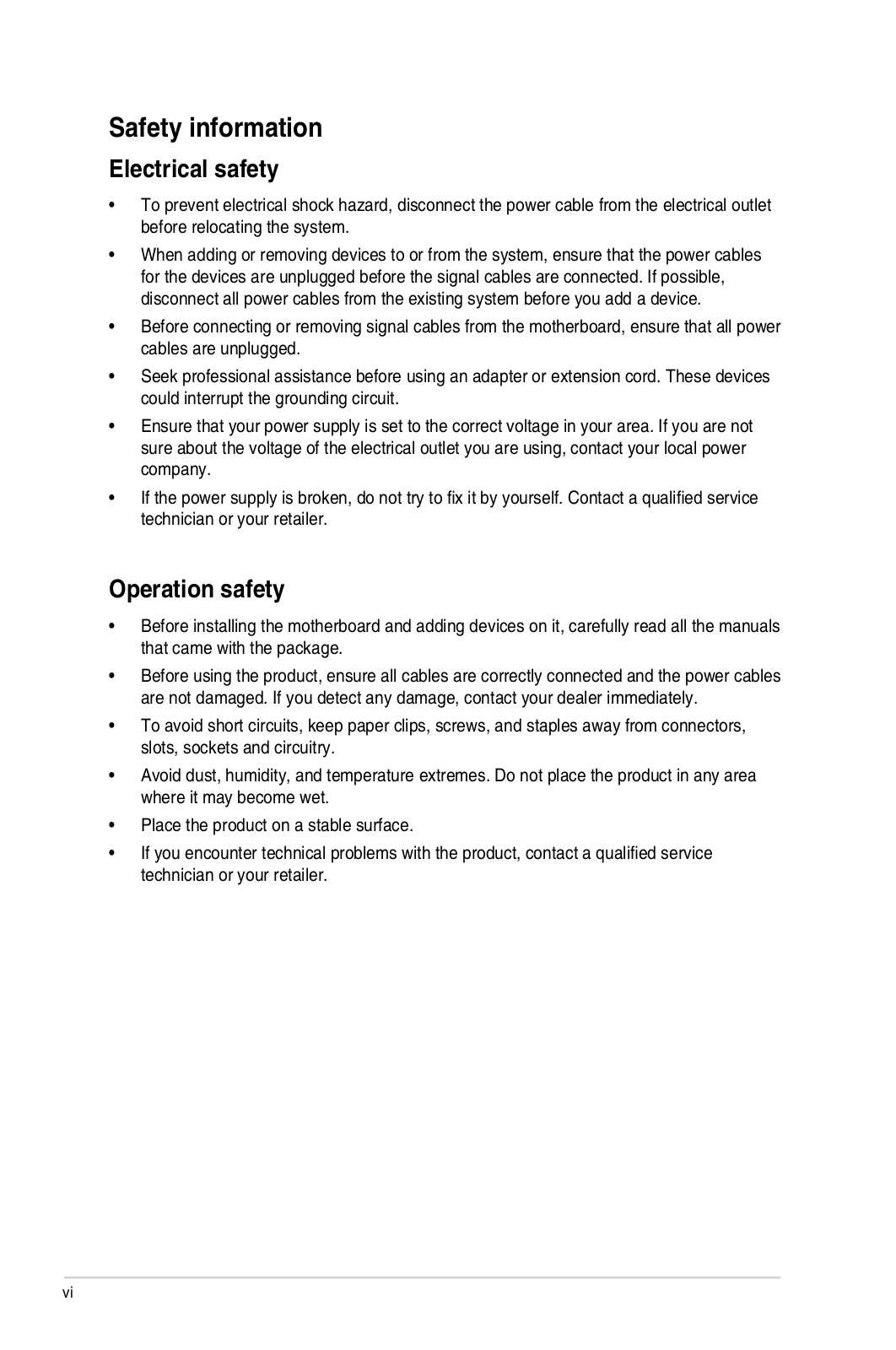
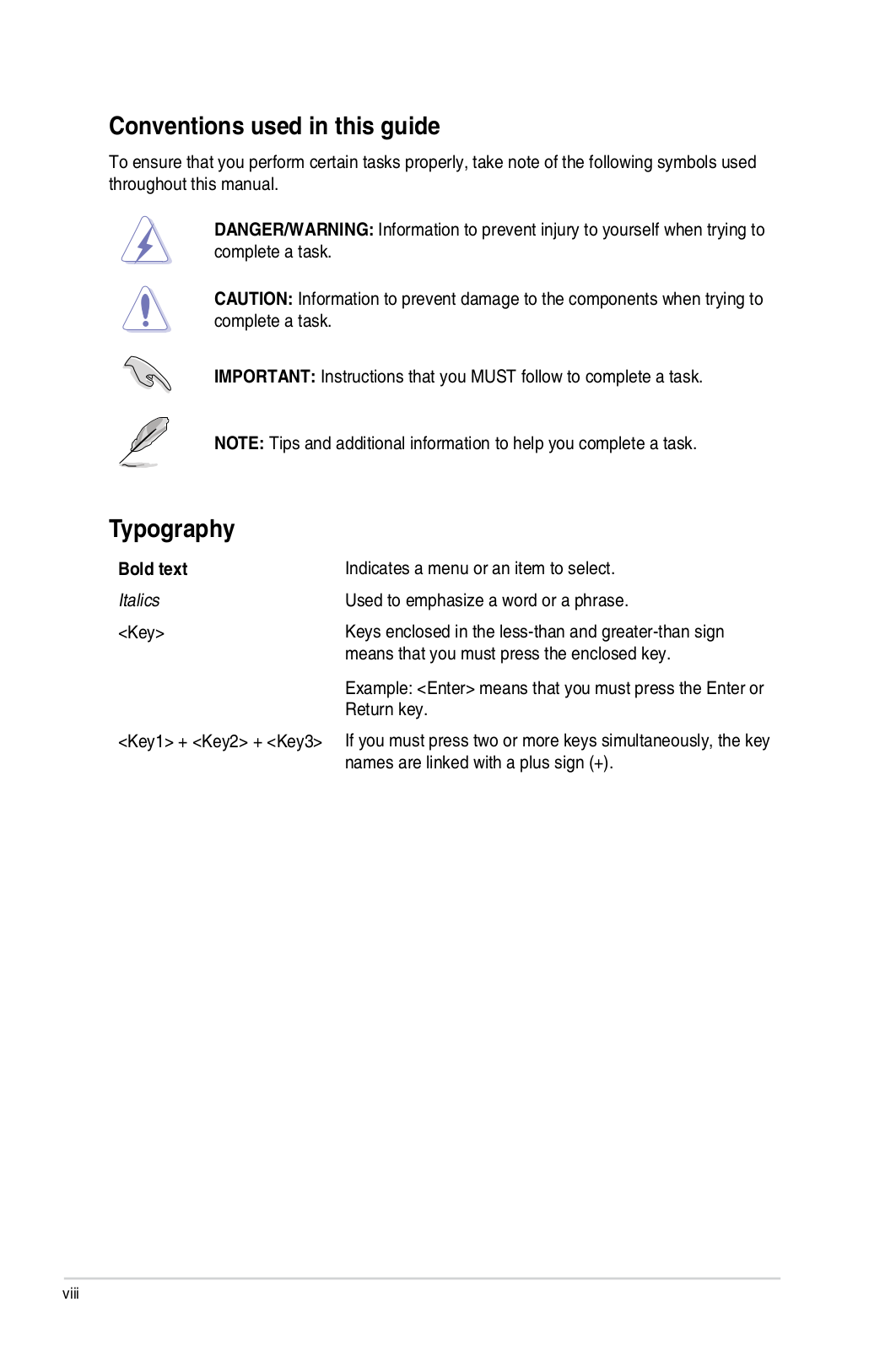
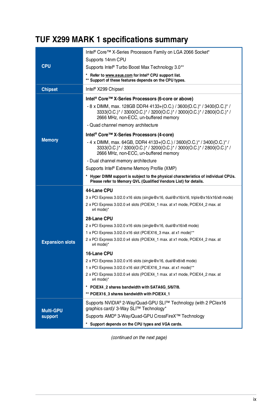
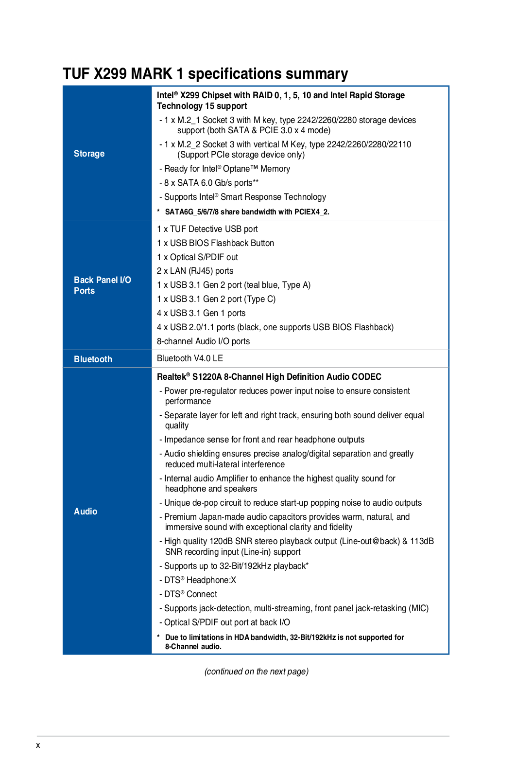
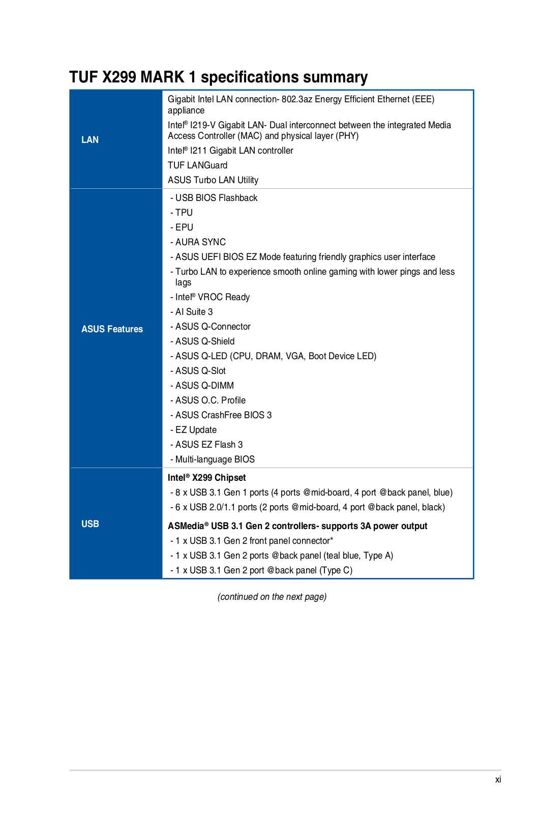
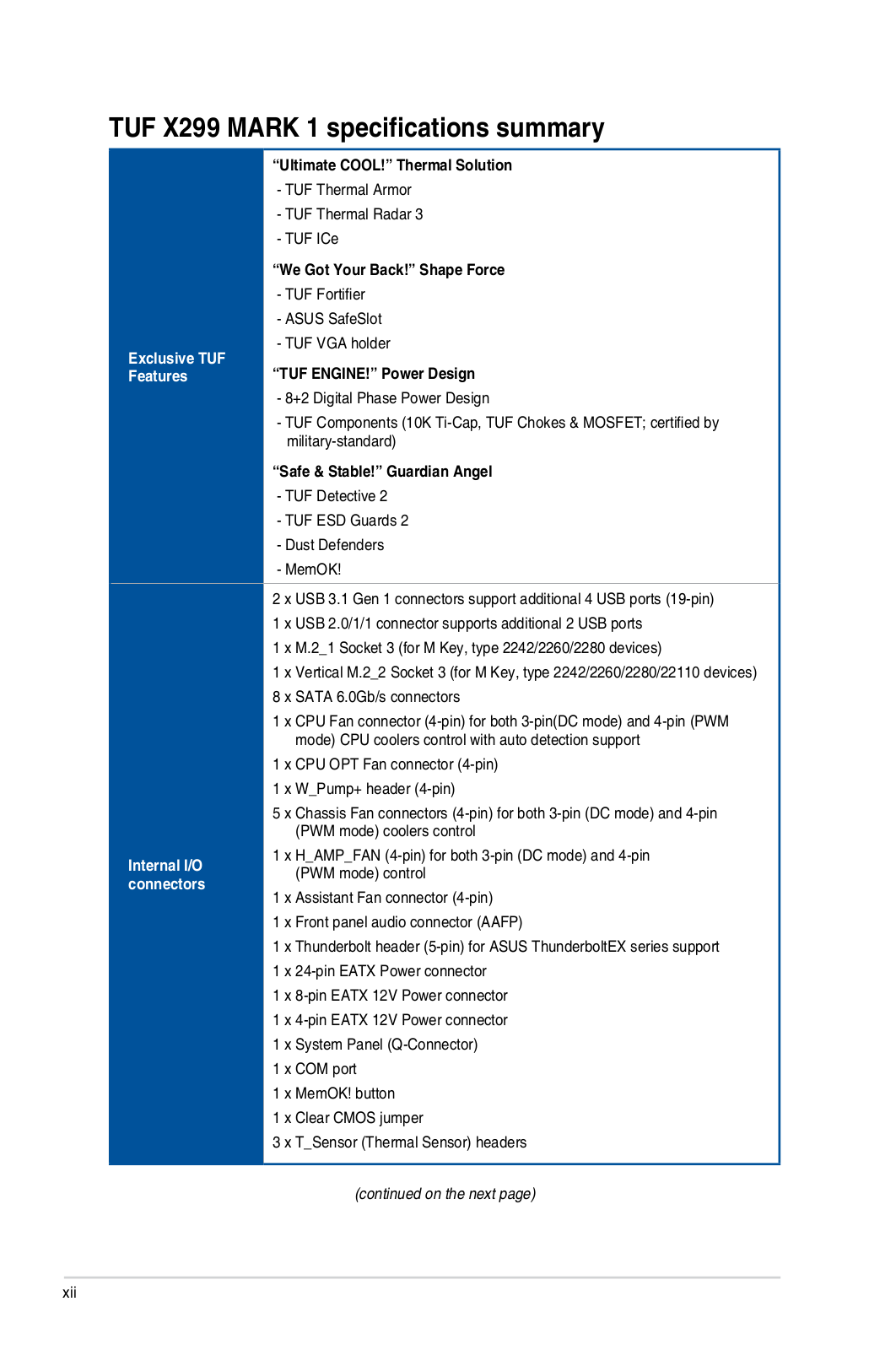
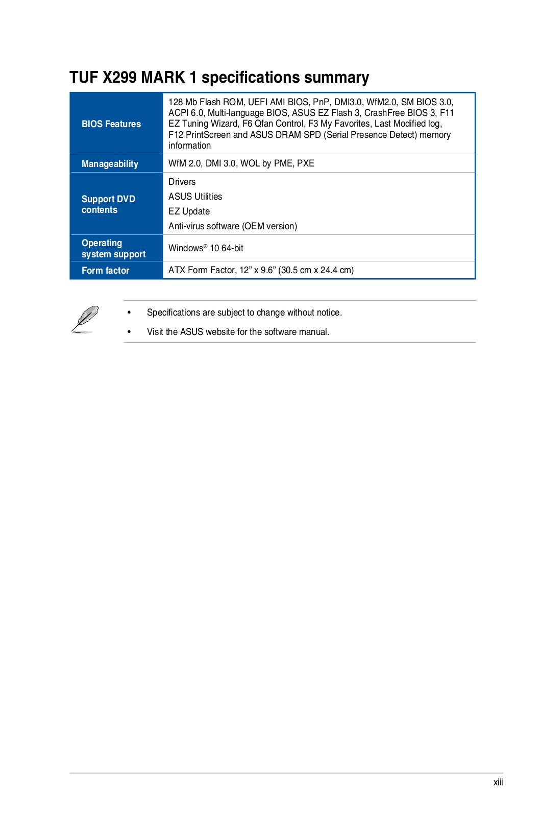
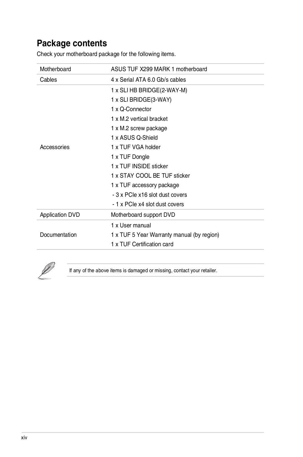
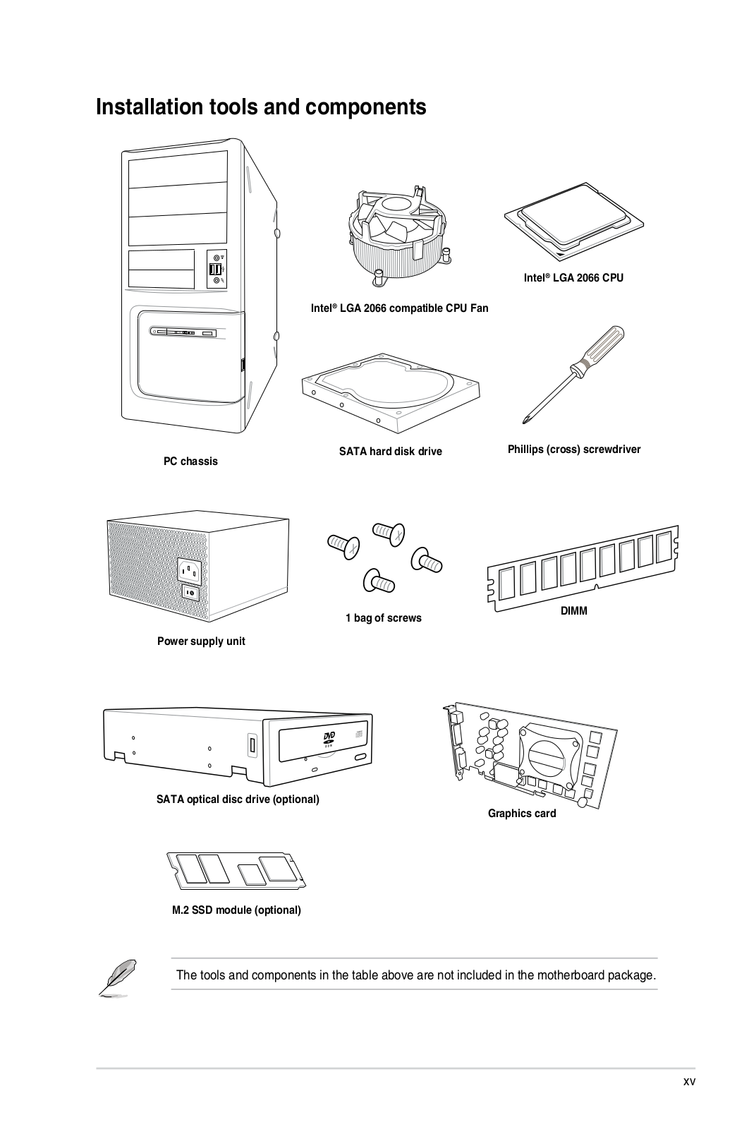


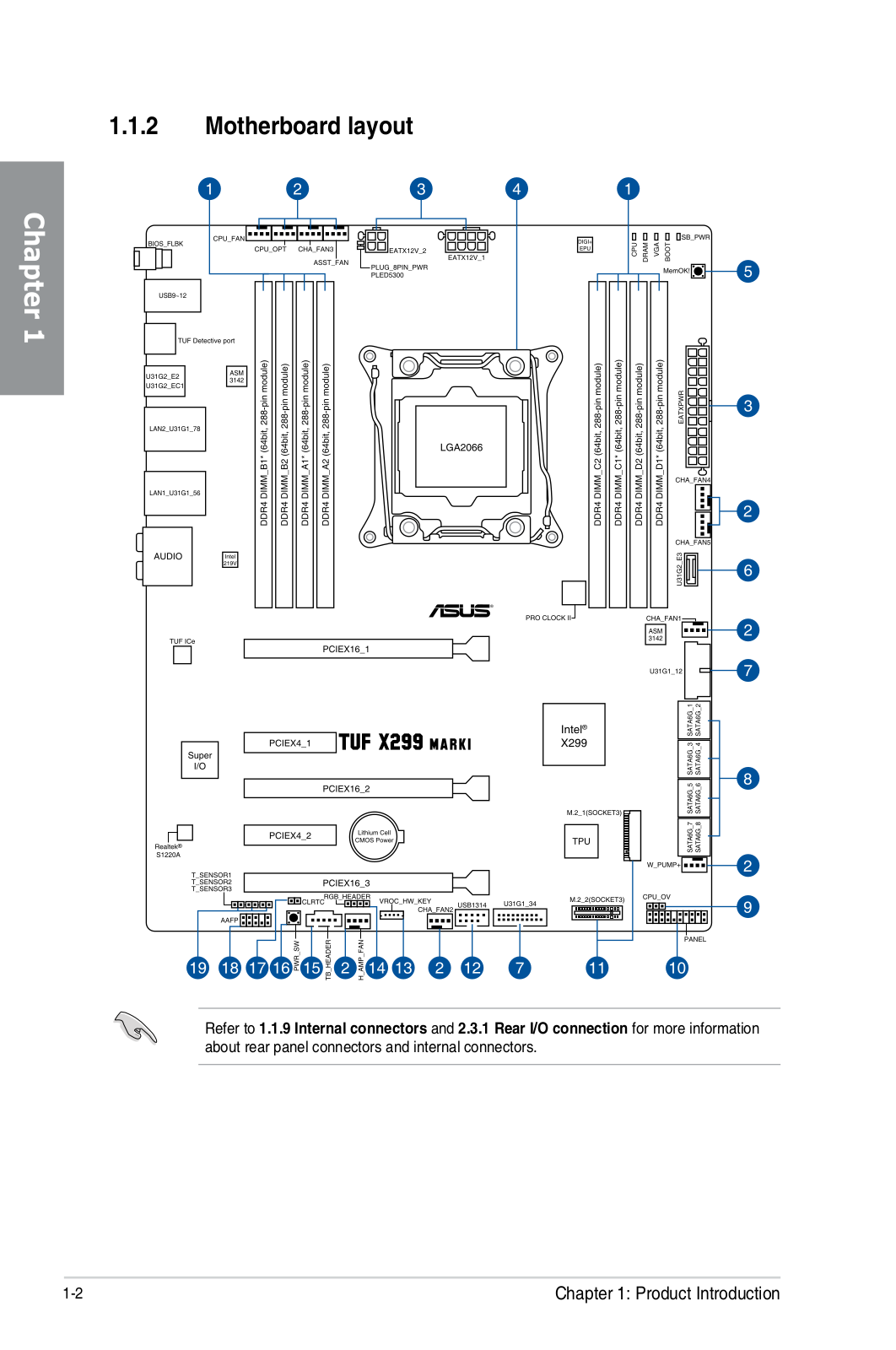
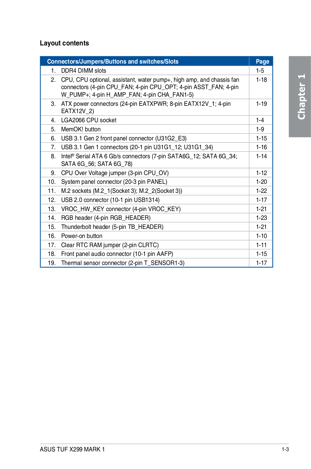
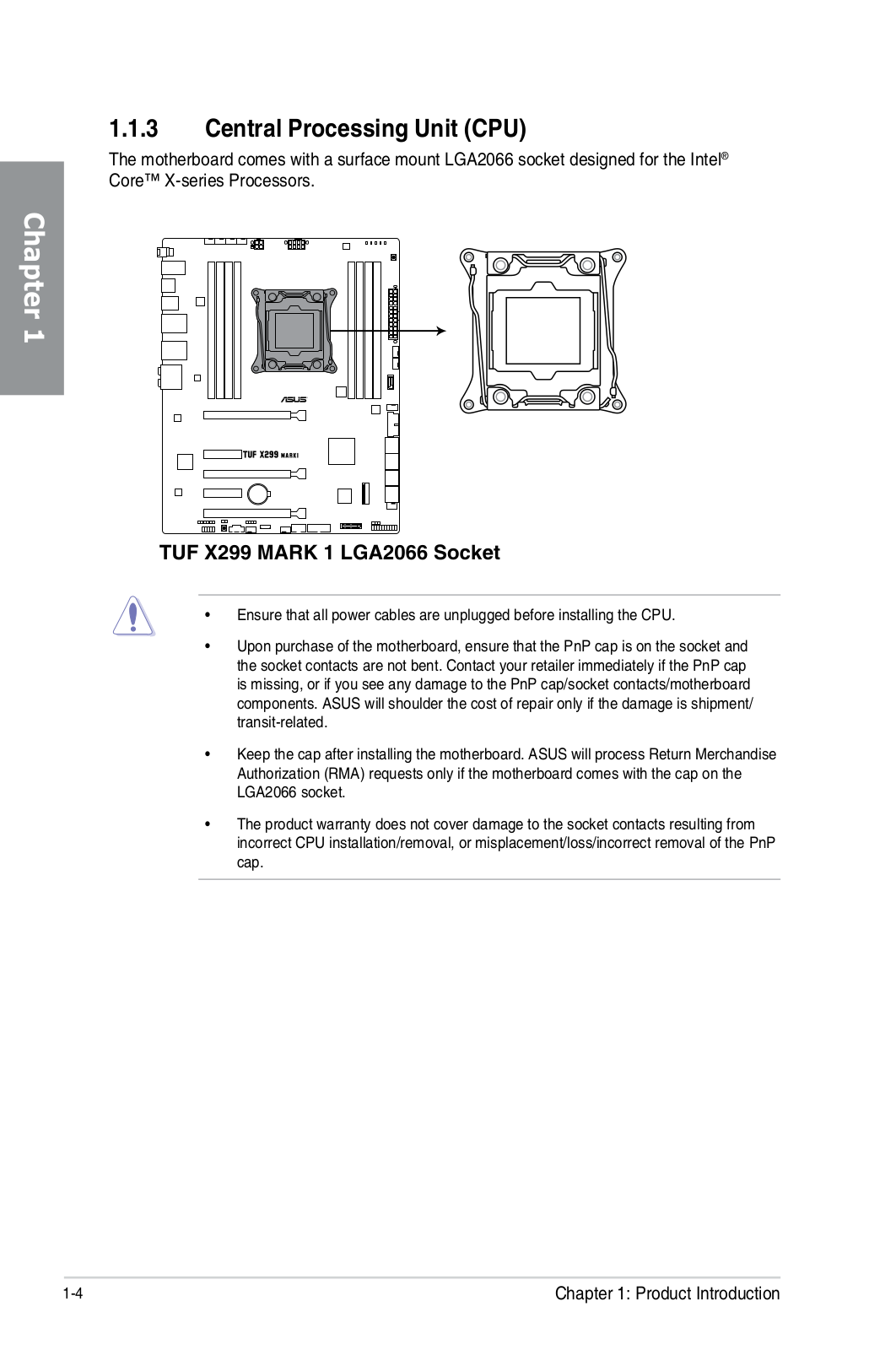
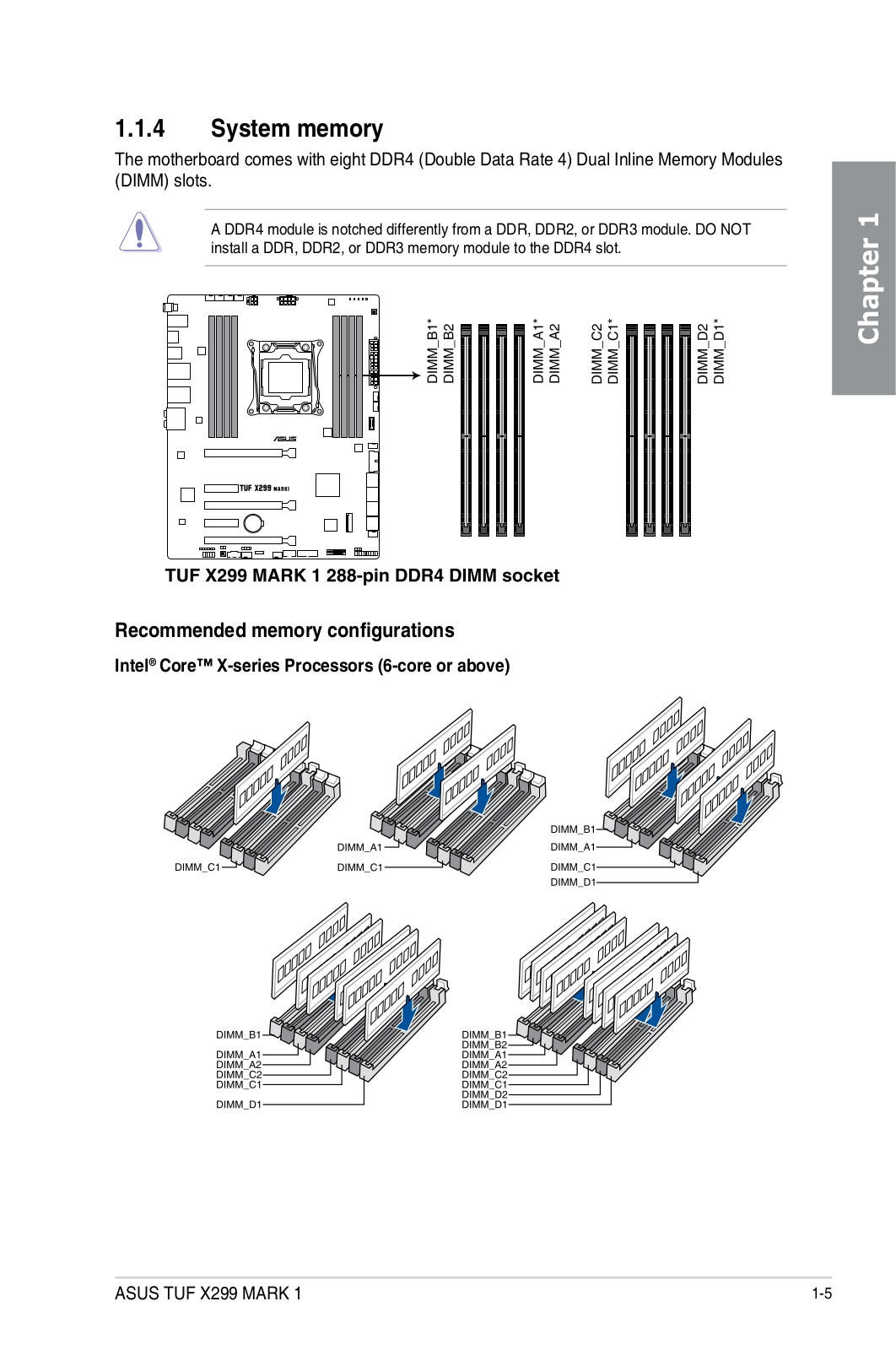
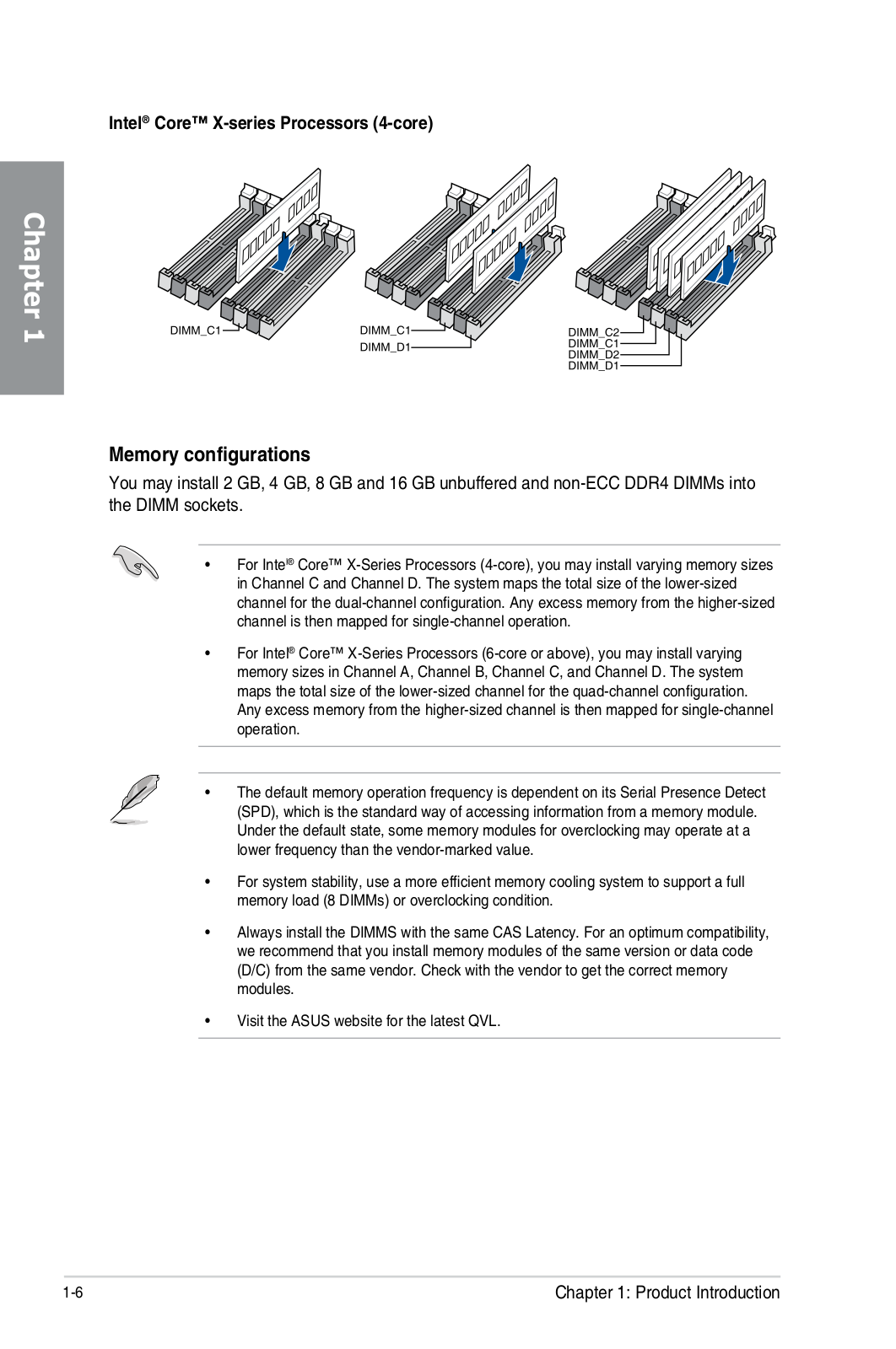
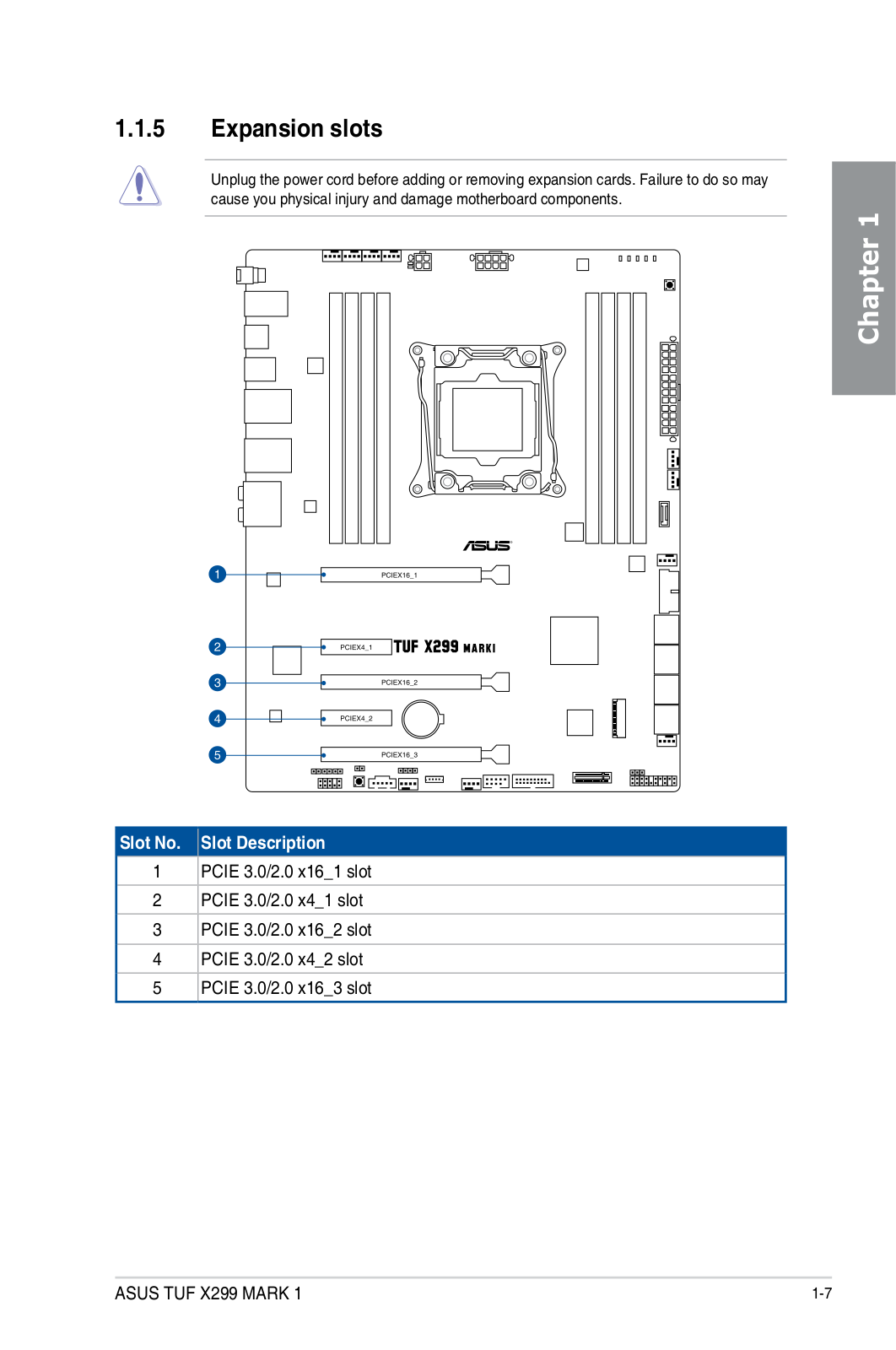
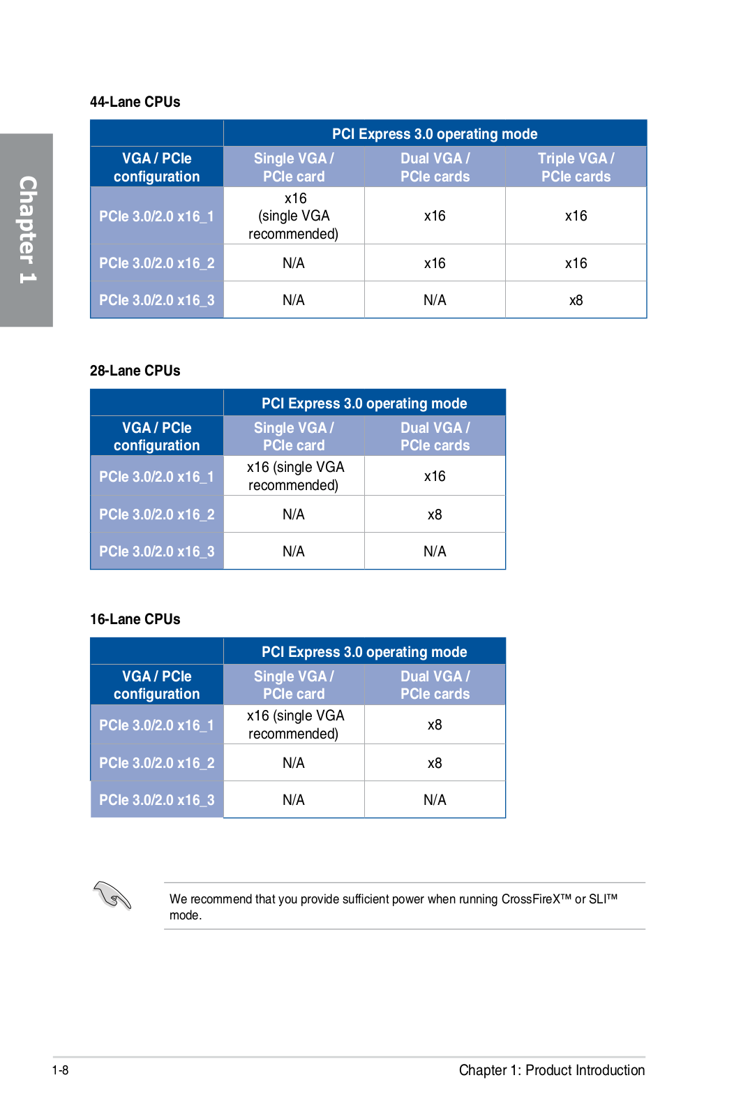
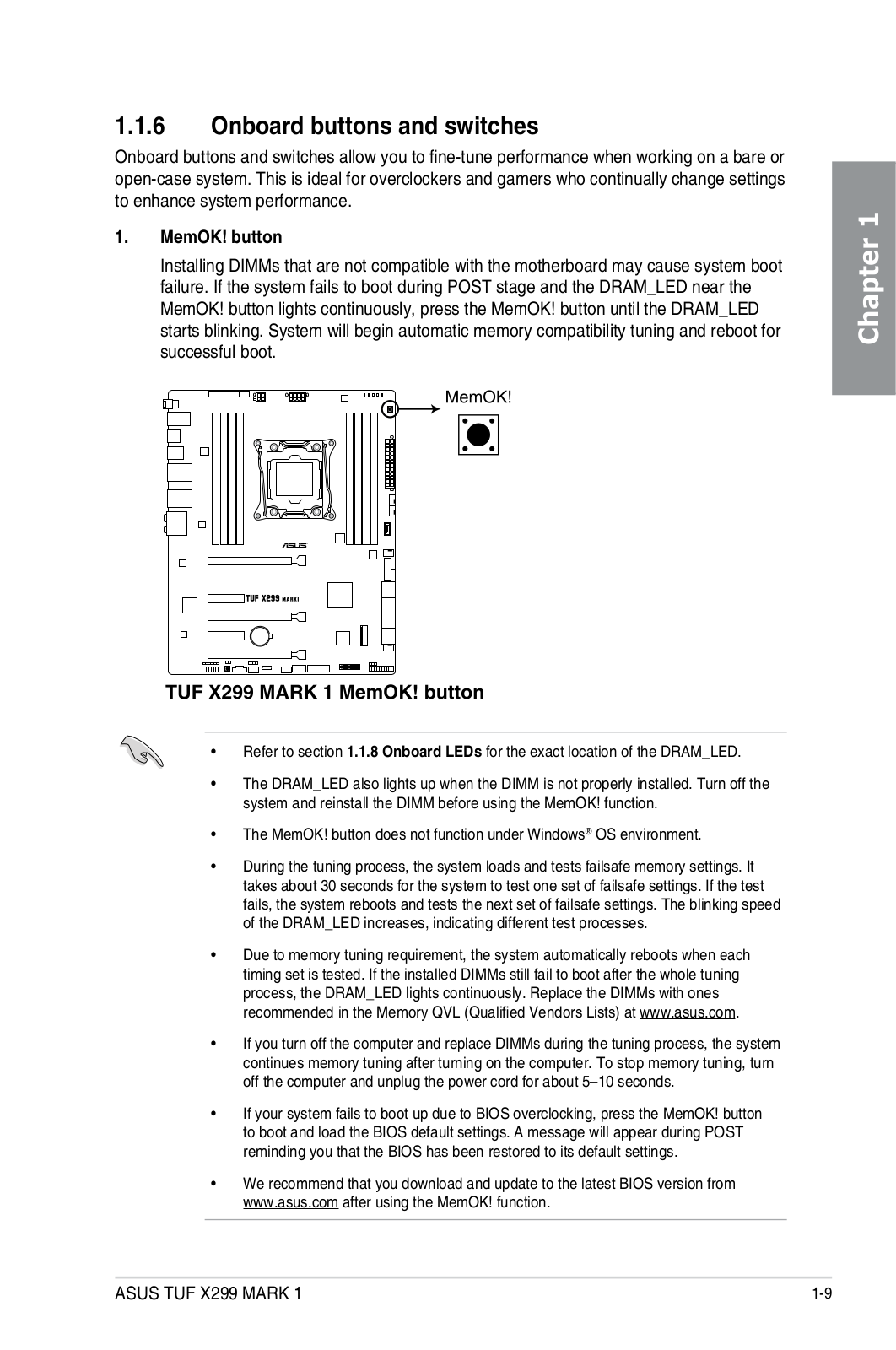
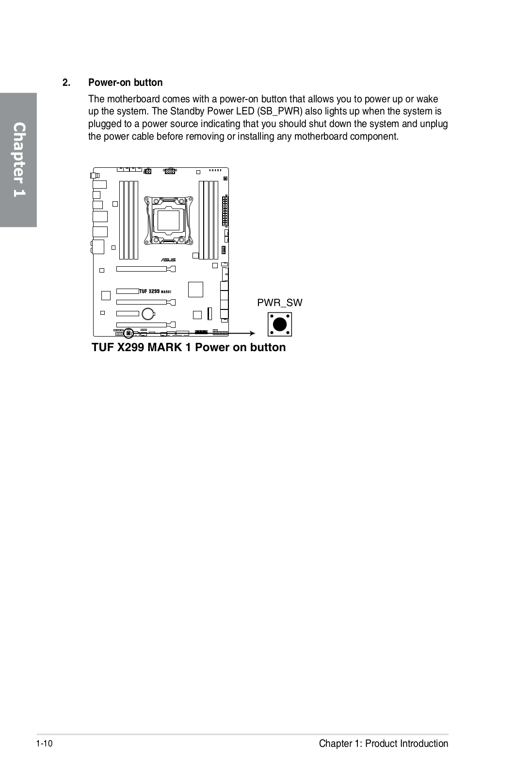
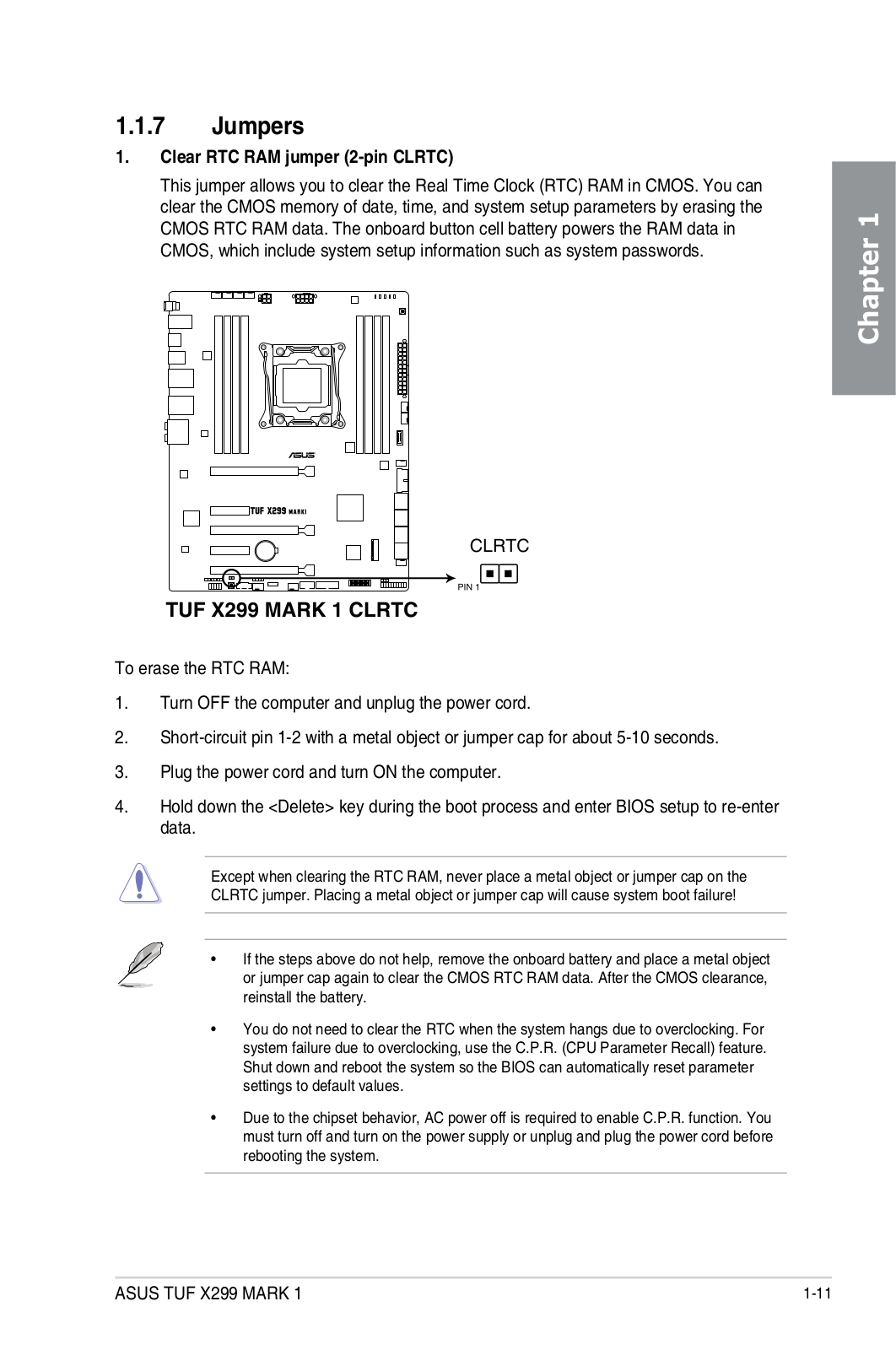
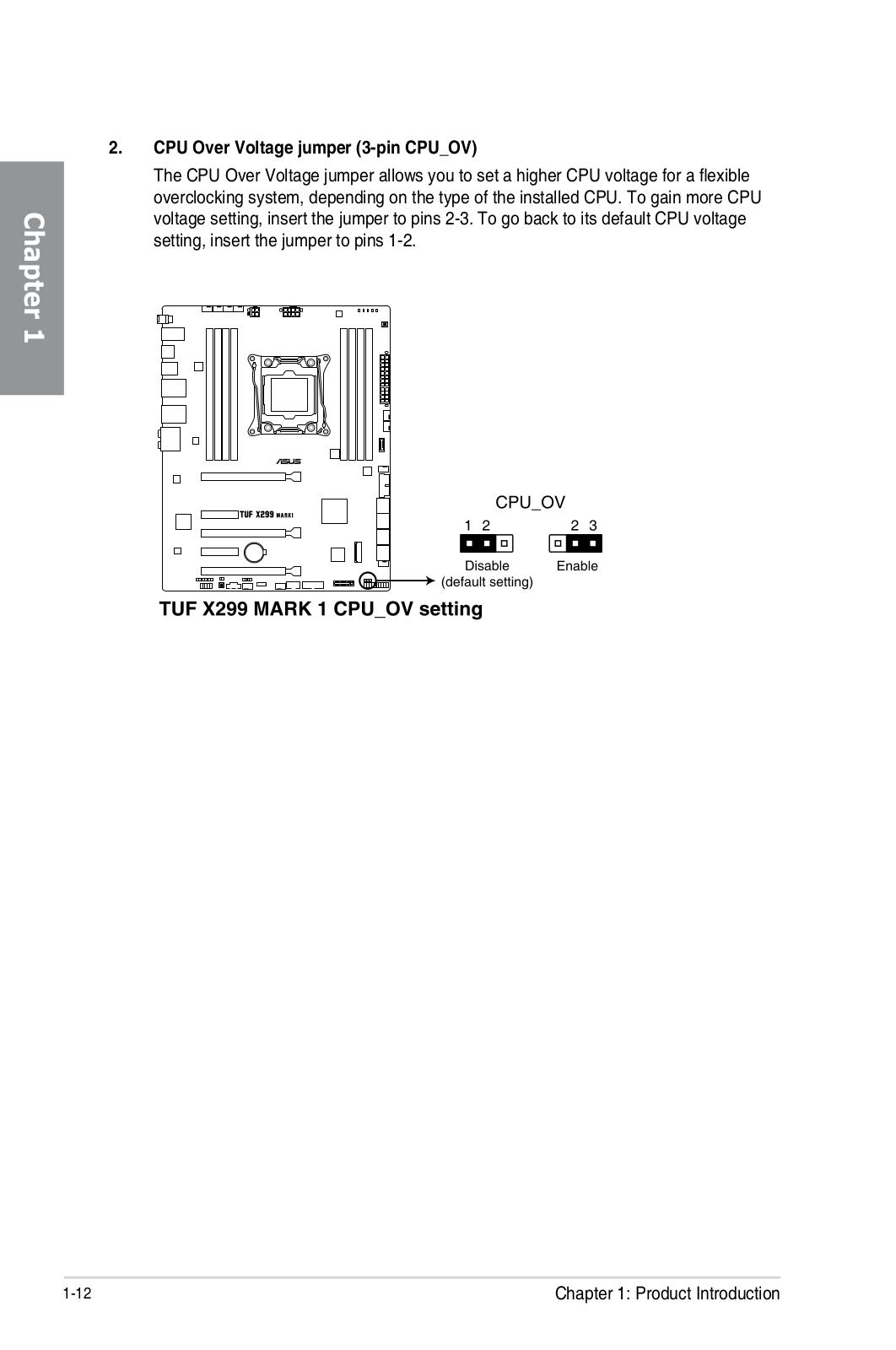
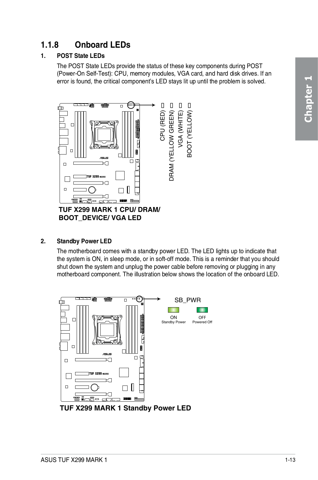
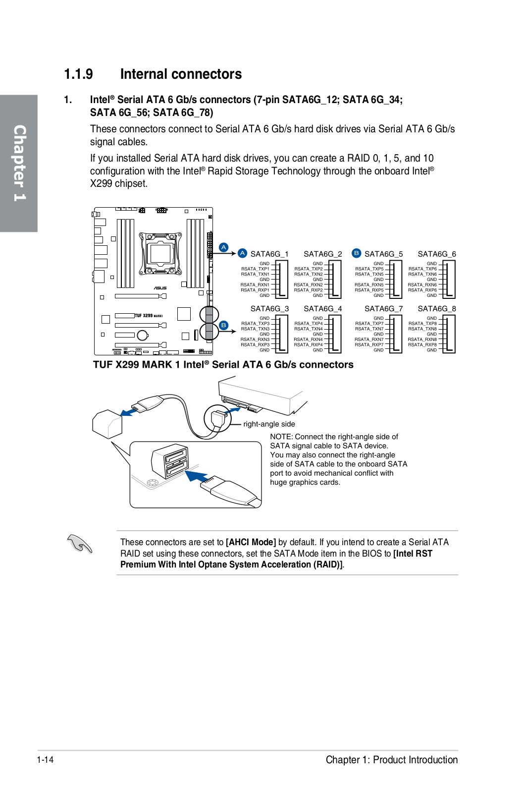
Loading…
+ 82 hidden pages
You need points to download manuals.
1 point = 1 manual.
You can buy points or you can get point for every manual you upload.
Buy points
Upload your manuals
Manuals.eu
- Manuals.eu
- ASUS
- Computers & Peripherals
- Motherboards
- Intel platform
- TUF X299 MARK 1
- User’s Manual(English)
×
1
2
3
4
5
6
7
8
9
10
11
12
13
14
15
16
17
18
19
20
21
22
23
24
25
26
27
28
29
30
31
32
33
34
35
36
37
38
39
40
41
42
43
44
45
46
47
48
49
50
51
52
53
54
55
56
57
58
59
60
61
62
63
64
65
66
67
68
69
70
71
72
73
74
75
76
77
78
79
80
81
82
83
84
85
86
87
88
89
90
91
92
93
94
95
96
97
98
99
100
101
102
103
104
105
106
107
108
109
110
111
112
⟨
⟩
Copyright © Manuals.eu
Agreement
Privacy Policy
Contact us
FAQ: Types of Manuals and Their Contents
Asus TUF X299 MARK 1 Manuals come in various types, each serving a specific purpose to help users effectively operate and maintain their devices. Here are the common types of Asus TUF X299 MARK 1 User Guides and the information they typically include:
- User Manuals: Provide comprehensive instructions on how to use the device, including setup, features, and operation. They often include troubleshooting tips, safety information, and maintenance guidelines.
- Service Instructions: Designed for technicians and repair professionals, these manuals offer detailed information on diagnosing and repairing issues with the device. They include schematics, parts lists, and step-by-step repair procedures.
- Installation Guides: Focus on the installation process of the device, providing detailed instructions and diagrams for proper setup. They are essential for ensuring the device is installed correctly and safely.
- Maintenance Manuals: Provide guidance on routine maintenance tasks to keep the device in optimal condition. They cover cleaning procedures, part replacements, and regular servicing tips.
- Quick Start Guides: Offer a concise overview of the essential steps needed to get the device up and running quickly. They are ideal for users who need immediate assistance with basic setup and operation.
Each type of Asus TUF X299 MARK 1 instruction is designed to address specific needs, ensuring users have the necessary information to use, maintain, and repair their devices effectively.
Related Instructions for Asus TUF X299 MARK 1:
1
X205T
E-manual Asus X205T User Manual (E-manual), @N6U1Y1
110
691
139
3
PIKE 2008 IMR
72
433
74
4
E45M1-M PRO
Guía de inicio rápido PDF User Manual (@271M7P), Asus E45M1-M PRO Motherboard (Wed 11.2024)
12
433
104
5
MZ27A Series
28
1376
344
7
PN30
Operation & user’s manual Asus Desktop Operation & user’s manual (File: asus-pn30-operation-user-s-manual-88, 18th Sep 2024)
88
1051
179
8
RT-N12+ B1
Quick start manual PDF User Manual (@DNNE9S), Asus RT-N12+ B1 Network Router (19th Nov 2024)
2
1395
279
9
W193T
Service manual PDF Manual (@S13HT3), Asus W193T Monitor (Friday 04-10-2024)
109
326
53
Motherboard Devices by Other Brands:
|
ASROCK G31DE Specifications Manual: ASROCK G31DE (E81158, Upd.Tuesday 04-02-2025) Detail Specification 04 Feb 2025 | 2 |
|
|
SMSC LAN9514 Datasheet User Guide: SMSC LAN9514 (VI7B2Q, Upd.16.04.2025) SMSC LAN9514 16 Apr 2025 | 47 |
|
|
Gigabyte GA-MA69VM-S2 Operation & User’s Manual GA-MA69VM-S2 Operation & user’s manual — 5FJH2Q GA-MA69VM-S2 12 Sep 2024 | 88 |
|
|
Intel AP440FX Technical Product Specification Intel Motherboard Technical product specification (File: intel-ap440fx-technical-product-specification-74, Saturday 04-01-2025) AP440FX Motherboard 04 Jan 2025 | 74 |
Categories:
Cell Phone Accessories
All-in-one pcs
Network Accessory
Led projector
Microphone
Security Sensors