
D-Link
DGS-1216T Инструкция по эксплуатации
Популярность:
2612 просмотры
Подсчет страниц:
61 страницы
Тип файла:
Размер файла:
1.7 Mb

Руководство по эксплуатации интернет коммутатор D-Link DGS-1216T 16-Port
скачать мануал на русском языке 16-ти портовый интернет коммутатор D-Link DGS-1216T
Инструкция по эксплуатации для пользователя интернет коммутатор D-Link DGS-1216T 16-Port содержит информацию о распаковке и установке. Распаковка устройства не сложная, но требует определенной сноровки и знаний, которые можно получить из справочника для пользователя, прилагаемого в комплекте. Откройте упаковочные коробки коммутатора и аккуратно распакуйте его.
При установке учитывайте следующие указатели: Установите коммутатор в достаточно прохладном и сухом месте. Смотрите технический спецификации для приемлемой температуры и влажности эксплуатации диапазоны. Установите коммутатор в месте, свободном от сильного электромагнитного поля генераторы (например, двигатели), вибрации, пыли и прямого воздействия солнечных лучей. Оставьте не менее 10 см свободного пространства в передней и задней части втулки для вентиляции. Объедините коммутатор с прилагаемыми винтами. Затем используйте винты, прилагаемые к стойке для оборудования, для крепления каждого их них. Переключатель расположен в стойке. Установите коммутатор в стойку.
Инструкция подключение сетевого кабеля. Коммутатор поддерживает 1000 Мбит / с Gigabit Ethernet, который работает в режиме автосогласования режим и 10 Мбит / с Ethernet или 100 Мбит / с Fast Ethernet, которые работает как в полудуплексном, так и в полнодуплексном режиме и гигабитном режиме 1000 Мбит / с Ethernet работает в дуплексном режиме, используя четыре пары кабелей категории 5. Эти порты RJ-45 являются портами типа Auto-MDI. Переключатель может автоматически преобразовать в тип MDI-II или MDI-X, так что вы можете просто сделать легкий соединение, не беспокоясь, если вы используете стандарт или перекрестный кабель RJ45.
Мощность переменного тока. Коммутатор использовал источник питания переменного тока 100-240В переменного тока, 50-60 Гц. выключатель питания расположен на задней панели устройства рядом с источником переменного тока разъем питания и системный вентилятор. Блок питания коммутатора будет автоматически адаптируется к местному источнику питания и может быть включен без подключения какого-либо или всех кабелей сегмента локальной сети.
Повышенная скорость и дополнительная пропускная способность, предлагаемые Gigabit Ethernet важно справиться с узкими местами сети, которые часто развиваться по мере того, как компьютеры и их шины становятся быстрее и все больше пользователей используют приложения, которые генерируют больше трафика. Обновление ключевых компонентов, такие как ваша магистраль и серверы к Gigabit Ethernet могут значительно улучшить время отклика сети, а также значительно ускорить трафик между вашими подсетями.
Gigabit Ethernet обеспечивает быстрое соединение по оптоволокну для поддержки видеоконференцсвязь, сложная обработка изображений и другие подобные данные Приложения. Аналогично, поскольку передача данных происходит в 10 раз быстрее, чем Fast Ethernet, серверы, оснащенные сетевыми картами Gigabit Ethernet, способны выполнить 10 раз количество операций за то же количество времени. Кроме того, феноменальная пропускная способность обеспечивается Gigabit Ethernet является наиболее экономически эффективным методом, чтобы воспользоваться сегодня и завтрашнее стремительно улучшающееся межсетевое взаимодействие с коммутацией и маршрутизацией технологии. И с ожидаемыми достижениями в ближайшие годы кремниевая технология и цифровая обработка сигналов, которые позволят Гигабитный Ethernet в конечном итоге будет работать по неэкранированной витой паре (UTP) кабели, оснащающие вашу сеть мощным 1000-Мбит / с магистральное серверное соединение создает гибкую основу для следующее поколение продуктов сетевых технологий.
Технология Fast Ethernet. Растущее значение ЛВС и усложнение приложения для настольных компьютеров подпитывают потребность в высоких производительность сетей. Ряд технологий высокоскоростной локальной сети было предложено обеспечить большую пропускную способность и улучшить время отклика клиент / сервер. Среди них 100BASE-T (Fast Ethernet) обеспечивает бесперебойную, плавную эволюцию от текущая технология 10BASE-T. Неразрывный и гладкий характер эволюции и доминирующая потенциальная рыночная база, практически гарантирует экономичный и высокопроизводительный Fast Ethernet решения. Поскольку 100 Мбит / с Fast Ethernet совместим со всеми другими 10 Мбит / с Ethernet среды, он обеспечивает простое обновление и требует преимущество существующих инвестиций в оборудование, программное обеспечение и обучение персонала.
Технология переключения. Еще один подход к выходу за пределы технологии Ethernet это развитие технологии коммутации. Переключатель мостов. Пакеты Ethernet на уровне MAC-адреса протокола Ethernet передача между подключенным Ethernet или Fast Ethernet LAN сегменты. Коммутация является экономически эффективным способом увеличения общей сети емкость доступна пользователям в локальной сети. Переключатель увеличивается емкость и снижает нагрузку на сеть путем разделения локальной области сеть на разные сегменты, которые не конкурируют друг с другом для пропускной способности сети. Переключатель действует как высокоскоростной селективный мост между отдельные сегменты. Переключатель, не мешая другим сегменты, автоматически перенаправляет трафик, который должен идти от одного сегмент к другому. При этом общая емкость сети составляет умножить, сохраняя при этом ту же сеть и адаптер карты.
Инструкция и технология коммутации LAN является заметным улучшением по сравнению с предыдущее поколение сетевых мостов, которые характеризовались более высокие задержки. Маршрутизаторы также использовались, чтобы сегментировать локальную область сети, но стоимость маршрутизатора, настройка и обслуживание требуется сделать роутеры относительно непрактичными. Сегодня коммутаторы идеальны решение большинства видов проблем перегруженности локальной сети.
VLAN (виртуальная локальная сеть). VLAN — это группа конечных станций, которые не ограничены физическое местоположение и может общаться, как если бы общий эфир домен, локальная сеть. Основной утилитой использования VLAN является уменьшение задержка и необходимость в маршрутизаторах, используя вместо этого более быстрое переключение. Другая утилита VLAN включает в себя: Безопасность, Безопасность повышается с уменьшением возможностей в подслушивание в широковещательной сети, потому что данные будут переключаться только тем конфиденциальным пользователям в сети VLAN. Снижение затрат, VLAN могут быть использованы для создания нескольких широковещательных домены, что исключает необходимость дорогих маршрутизаторов. VLAN на основе порта (или группы портов) является распространенным методом реализация VLAN, и это тот, который поставляется в коммутаторе.
Характеристики коммутатора D-Link. G Порты Gigabit Ethernet с автоматическим согласованием 16 ? 10/100/1000 Мбит / с Ports Все порты RJ45 поддерживают автоматический MDI / MDIX, поэтому нет необходимости используйте перекрестные кабели или порт восходящей связи Полудуплексный режим передачи для скорости соединения 10 Мбит / с и 100Mbps. Полнодуплексный режим передачи для скорости соединения 10 Мбит / с, 100 Мбит / с и 1000 Мбит / с Speed Скорость приема и передачи по проводам Capability Возможность схемы хранения и пересылки для поддержки скорости адаптация и обеспечение целостности данных.
Поздравляем с покупкой 16-портового DGS-1216T 10/100/1000 Мбит / с Gigabit Ethernet + 2-портовый мини-GBIC Web Smart Переключатель. Это устройство объединяет 1000 Мбит / с Gigabit Ethernet, 100 Мбит / с Возможности сетей Fast Ethernet и Ethernet 10 Мбит / с гибкий пакет. В этом руководстве рассказывается, как установить и настроить DGS-1216T. Web Smart Switch. Условия Usage в этом руководстве термин «Переключатель» (заглавная буква первой буквы) относится к вашему DGS-1216T Web Smart Switch и «переключатель» (первая буква в нижнем регистре) относится к другим коммутаторам Ethernet.
В этой инструкции пользователя описываются функции DGS-1216T и некоторые справочная информация о Ethernet Fast Ethernet Gigabit Ethernet технология переключения. Технология Gigabit Ethernet Gigabit Ethernet является расширением IEEE 802.3 Ethernet, использующим та же структура пакета, формат и поддержка протокола CSMA CD, полный дуплекс, управление потоком и объекты управления, но с десятикратным увеличение теоретической пропускной способности более 100 Мбит / с Fast Ethernet и 100-кратное увеличение по сравнению с 10-Мбит / с Ethernet. Так как это совместимо со всеми сетевыми средами 10 Мбит / с и 100 Мбит / с, гигабит Ethernet обеспечивает простое обновление без потери. Существующие инвестиции компании в оборудование, программное обеспечение и обучение персонала.
скачать файл
download user’s guide D-Link DGS-1216T File-Size: 1,7 Мб

Table of Contents D-Link Web Smart Switch User Manual
Table of Contents
Table of Contents …………………………………………………………………………………………………………………………… i
About This Guide…………………………………………………………………………………………………………………………… 1
Online Resources…………………………………………………………………………………………………………………………. 1
Terms/Usage……………………………………………………………………………………………………………………………….. 1
Copy Right and Trademarks…………………………………………………………………………………………………………..1
Hardware Installation …………………………………………………………………………………………………………………….. 2
Step1: Unpacking…………………………………………………………………………………………………………………………. 2
Step2: Switch Installation………………………………………………………………………………………………………………. 2
Desktop or Shelf Installation……………………………………………………………………………………………………….. 2
Rack Installation……………………………………………………………………………………………………………………….. 2
Step 3 – Plugging in the AC Power Cord…………………………………………………………………………………………. 3
Power Failure …………………………………………………………………………………………………………………………… 3
Getting Started………………………………………………………………………………………………………………………………. 4
Management Options……………………………………………………………………………………………………………………. 4
Using Web-based Management Utility……………………………………………………………………………………………..4
Supported Web Browsers ………………………………………………………………………………………………………….. 4
Connecting to the Switch……………………………………………………………………………………………………………. 4
Login Web-based Management Utility ………………………………………………………………………………………….5
Smart Wizard ………………………………………………………………………………………………………………………………. 5
Web-based Management Utility………………………………………………………………………………………………………5
SmartConsole Utility………………………………………………………………………………………………………………………5
Product Introduction……………………………………………………………………………………………………………………… 7
DGS-1216T…………………………………………………………………………………………………………………………………. 7
Front Panel………………………………………………………………………………………………………………………………. 7
Rear Panel……………………………………………………………………………………………………………………………….. 8
DGS-1224T…………………………………………………………………………………………………………………………………. 8
Front Panel………………………………………………………………………………………………………………………………. 8
Rear Panel……………………………………………………………………………………………………………………………….. 9
DGS-1224TP……………………………………………………………………………………………………………………………….. 9
Front Panel………………………………………………………………………………………………………………………………. 9
Rear Panel……………………………………………………………………………………………………………………………… 10
DGS-1248T……………………………………………………………………………………………………………………………….. 10
Front Panel…………………………………………………………………………………………………………………………….. 10
Rear Panel……………………………………………………………………………………………………………………………… 11
SmartConsole Utility ……………………………………………………………………………………………………………………. 12
SmartConsole Settings ………………………………………………………………………………………………………………..12
Utility Settings………………………………………………………………………………………………………………………….12
Log………………………………………………………………………………………………………………………………………… 13
Trap………………………………………………………………………………………………………………………………………. 13
File…………………………………………………………………………………………………………………………………………13
Help………………………………………………………………………………………………………………………………………. 14
Device Configurations…………………………………………………………………………………………………………………. 15
Add(+), Delete(-) and Discover the device………………………………………………………………………………….. 17
Device List…………………………………………………………………………………………………………………………………. 18
Configuration………………………………………………………………………………………………………………………………. 19
Smart Wizard Configuration…………………………………………………………………………………………………………. 19
Password Settings…………………………………………………………………………………………………………………… 19
i

Table of Contents D-Link Web Smart Switch User Manual
SNMP Settings……………………………………………………………………………………………………………………….. 20
System Settings………………………………………………………………………………………………………………………. 21
Identifying the Web-based Management Utility………………………………………………………………………………. 22
Tool Menu…………………………………………………………………………………………………………………………………. 22
Reset …………………………………………………………………………………………………………………………………….. 22
Configure Backup & Restore……………………………………………………………………………………………………..23
Firmware Backup and Upload…………………………………………………………………………………………………… 23
System Reboot……………………………………………………………………………………………………………………….. 24
Setup Menu………………………………………………………………………………………………………………………………..24
System > System Settings ………………………………………………………………………………………………………..24
System > Trap Settings……………………………………………………………………………………………………………. 25
System > Port Settings……………………………………………………………………………………………………………..26
System > SNMP Settings…………………………………………………………………………………………………………. 26
System > Password Access Control………………………………………………………………………………………….. 28
Configuration > Jumbo Frame……………………………………………………………………………………………………28
Configuration > 802.1Q VLAN…………………………………………………………………………………………………… 28
Configuration >Asymmetric VLAN……………………………………………………………………………………………… 29
Configuration > 802.1Q Management VLAN………………………………………………………………………………..31
Configuration > Trunking………………………………………………………………………………………………………….. 31
Configuration > IGMP Snooping ……………………………………………………………………………………………….. 31
Configuration > 802.1D Spanning Tree………………………………………………………………………………………. 33
Configuration > Port Mirroring…………………………………………………………………………………………………… 34
Configuration > Power Saving…………………………………………………………………………………………………… 35
Power over Ethernet (PoE) > PoE Port Settings (Only for DGS-1224TP)………………………………………..35
Power over Ethernet (PoE) > PoE System Settings (Only for DGS-1224TP) …………………………………..36
QoS > 802.1p/DSCP Priority Settings………………………………………………………………………………………… 37
Security > Trusted Host…………………………………………………………………………………………………………….38
Security > Safeguard Engine……………………………………………………………………………………………………..39
Security > Broadcast Storm Control…………………………………………………………………………………………… 39
Security > 802.1X Settings……………………………………………………………………………………………………….. 40
Security > Mac Address Table > Static Mac ………………………………………………………………………………..41
Security > Mac Address Table > Dynamic Forwarding Table………………………………………………………… 41
Monitoring > Statistics……………………………………………………………………………………………………………… 42
Monitoring > Cable Diagnostics ………………………………………………………………………………………………… 42
Appendix A — Ethernet Technology…………………………………………………………………………………………………. 1
Gigabit Ethernet Technology …………………………………………………………………………………………………………. 1
Fast Ethernet Technology……………………………………………………………………………………………………………… 1
Switching Technology…………………………………………………………………………………………………………………… 1
Power over Ethernet (PoE)……………………………………………………………………………………………………………. 1
Appendix B — Technical Specifications …………………………………………………………………………………………… 3
Hardware Specifications ……………………………………………………………………………………………………………….. 3
Key Components / Performance…………………………………………………………………………………………………. 3
Port Functions …………………………………………………………………………………………………………………………..3
Physical & Environment …………………………………………………………………………………………………………….. 3
Emission (EMI) Certifications……………………………………………………………………………………………………… 3
Safety Certifications……………………………………………………………………………………………………………………3
Features……………………………………………………………………………………………………………………………………… 3
L2 Features ……………………………………………………………………………………………………………………………… 3
VLAN………………………………………………………………………………………………………………………………………. 3
iiii

Table of Contents D-Link Web Smart Switch User Manual
QoS (Quality of Service)…………………………………………………………………………………………………………….. 3
Security……………………………………………………………………………………………………………………………………. 3
Management…………………………………………………………………………………………………………………………….. 3
iii
About This Guide D-Link Web Smart Switch User Manual
About This Guide
This guide provides instructions to install D-Link Gigabit Ethernet Web Smart Switches DGS1216T/24T/24TP/48T, how to use the SmartConsole Utility, and to configure Web-based Management Utility
step-by-step.
Note: The model you have purchased may
appear slightly different from the illustrations
shown in the document. Refer Product
Instruction and Technical Specification section
for detailed information about your switch, its
components, network connections, and technical
specifications.
This guide is mainly divided into four parts:
1. Hardware Installation: Step-by-step hardware installation procedures
2. Getting Started: A startup guide for basic switch installation and settings
3. Smart Console Utility: An introduction to the central management system
4. Configuration: Information about the function descriptions and configuration settings
Online Resources
The website addresses are not prefixed with http:// because most of the current web browsers do not need it.
If you are using an older web browser, you may have to append http:// in the web address.
For the latest information about the Web Smart Switches, e-mail:
Resource Website
D-Link
Technical Support
www.dlink.com.tw
tsd.dlink.com.tw
Terms/Usage
In this guide, the term “Switch” (first letter is capitalized) refers to the Smart Switch, and “switch” (first letter in
lower case) refers to other Ethernet switches. Some technologies refer to terms “switch”, “bridge” and
“switching hubs” interchangeably, and both are commonly accepted for Ethernet switches.
A NOTE Alerts you to supplementary
information.
A CAUTION indicates potential property damage
or personal injury.
Copy Right and Trademarks
Information in this document is subjected to change without notice.
© 2007 D-Link Corporation. All rights reserved.
Reproduction in any manner whatsoever without the written permission of D-Link Corporation is strictly
forbidden.
Trademarks used in this text: D-Link and the D-LINK logo are trademarks of D-Link Corporation; Microsoft
and Windows are registered trademarks of Microsoft Corporation.
Other trademarks and trade names may be used in this document to refer to either the entities claiming the
marks and names or their products. D-Link Corporation disclaims any proprietary interest in trademarks and
trade names other than its own.
1
1 Hardware Installation D-Link Web Smart Switch User Manual
1 Hardware Installation
This chapter provides unpacking and installation information for the D-Link Web-Smart Switch.
Step1: Unpacking
Open the shipping carton and carefully unpack its contents. Please consult the packing list located in the
User Manual to make sure all items are present and undamaged. If any item is missing or damaged, please
contact your local D-Link reseller for replacement.
One D-Link Web-Smart Switch
One AC power cord
Four rubber feet
Screws and two mounting brackets
One Multi-lingual Getting Started Guide
User’s Guide CD with SmartConsole Utility program
If any item is found missing or damaged, please contact the local reseller for replacement.
Step2: Switch Installation
For safe switch installation and operation, it is recommended that you:
Visually inspect the power cord to see that it is secured fully to the AC power connector.
Make sure that there is proper heat dissipation and adequate ventilation around the switch.
Do not place heavy objects on the switch.
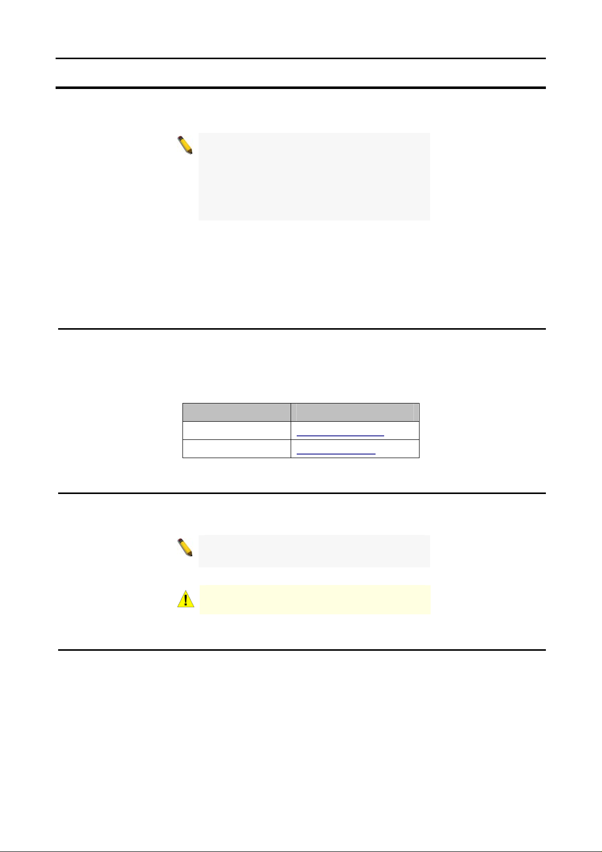
Desktop or Shelf Installation
When installing the switch on a desktop or shelf, the rubber feet included with the device must be attached
on the bottom at each corner of the device’s base. Allow enough ventilation space between the device and
the objects around it.
Figure 1 – Attach the adhesive rubber pads to the bottom
Rack Installation
The switch can be mounted in an EIA standard size 19-inch rack, which can be placed in a wiring closet with
other equipment. To install, attach the mounting brackets to the switch’s side panels (one on each side) and
secure them with the screws provided (please note that these brackets are not designed for palm size
switches).
Figure 2 – Attach the mounting brackets to the Switch
22
1 Hardware Installation D-Link Web Smart Switch User Manual
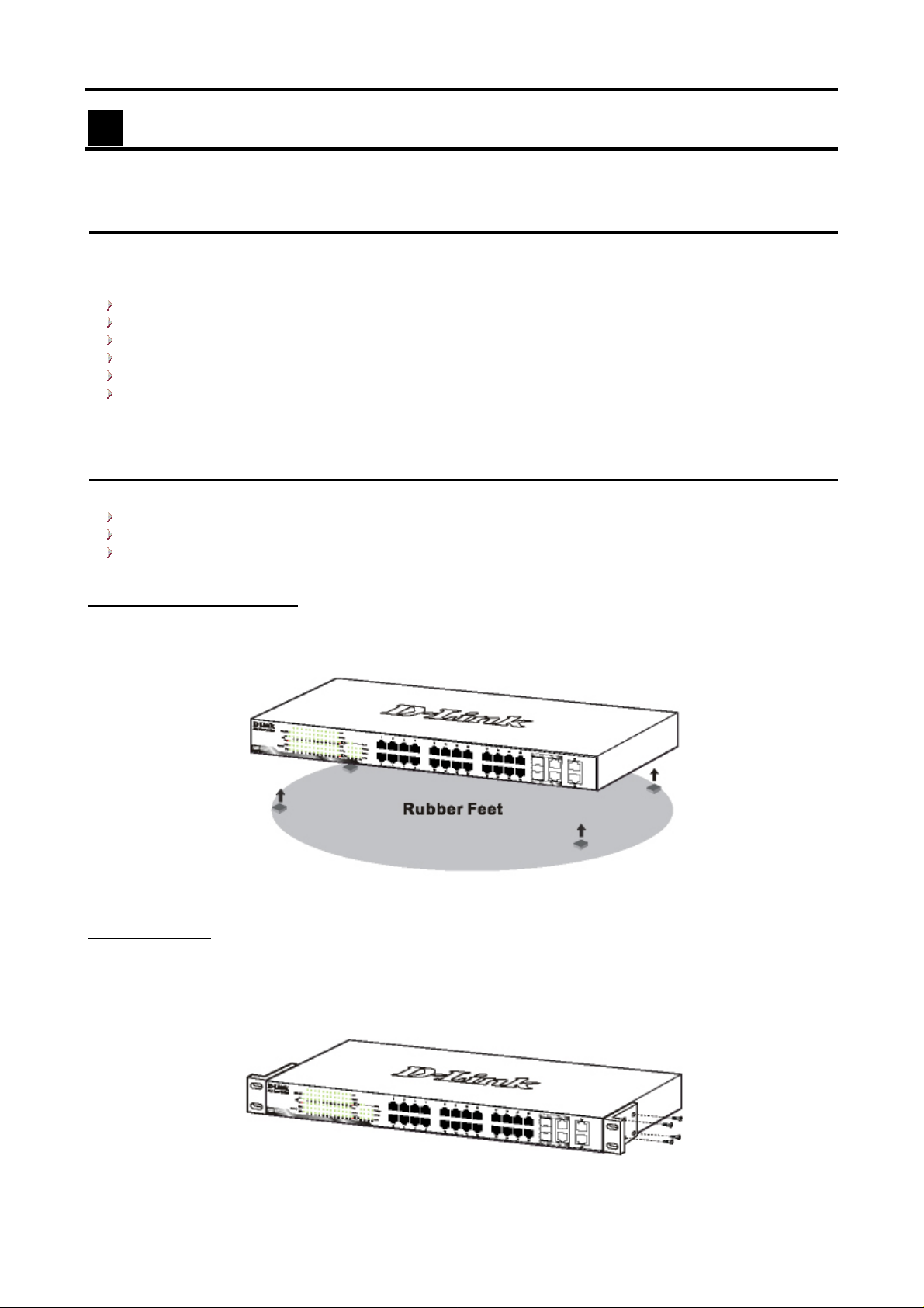
Then, use the screws provided with the equipment rack to mount the switch in the rack.
Figure 3 – Mount the Switch in the rack or chassis
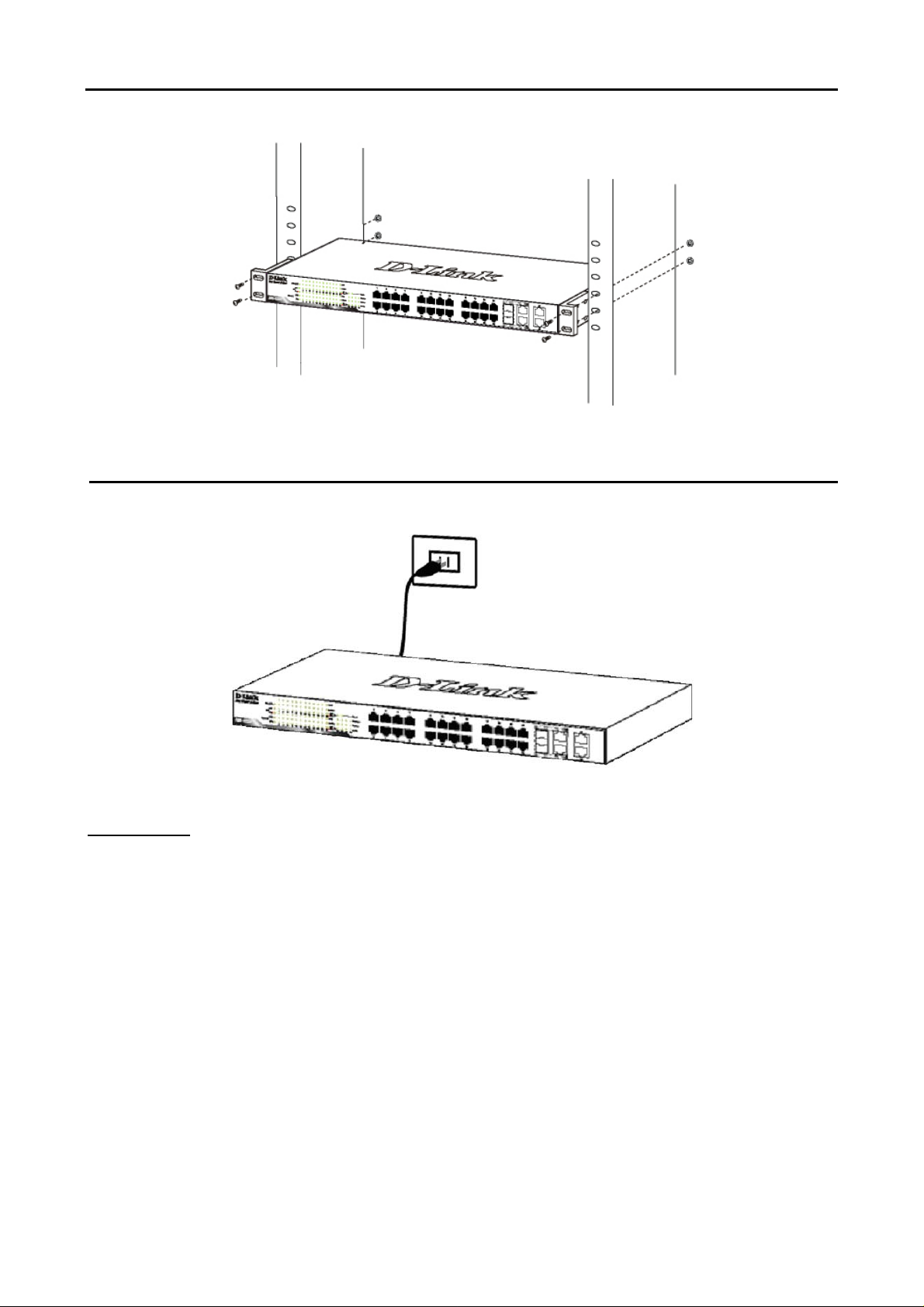
Step 3 – Plugging in the AC Power Cord
Users may now connect the AC power cord into the rear of the switch and to an electrical outlet (preferably
one that is grounded and surge protected).
Figure 4 –Plugging the switch into an outlet
Power Failure
As a precaution, the switch should be unplugged in case of power failure. When power is resumed, plug the
switch back in.
3
2 Getting Started D-Link Web Smart Switch User Manual
2 Getting Started
This chapter guides you how to get into and introduces the management interface of D-Link Web-Smart
Switch.
Management Options
The D-Link Web Smart Switch can be managed through any port on the device by using the Web-based
Management Utility or through any PC using the SmartConsole Utility.
If you want to manage only one D-Link Web Smart Switch, the Web-Based Management Utility is the better
option. Each switch must be assigned its own IP Address, which is used for communication with Web-Based
Management Utility or an SNMP network manager and the PC should have an IP address in the same range
as the switch.
However, if you want to manage multiple D-Link Web Smart Switches, the SmartConsole Utility is the better
option. Using the SmartConsole Utility, you don’t need to change the IP address of your PC and it is easy to
start the initial setting of multiple Smart Switches.
Please refer to the following detailed installation instructions for the Web-Based Management Utility and the
SmartConsole Utility.
Using Web-based Management Utility
After a successful physical installation, you can configure the Switch, monitor the LED panel, and display
statistics graphically using a web browser.
Supported Web Browsers
The embedded Web-based Management Utility currently supports the following web bro wsers:
Microsoft Internet Explorer ver. 6.0, 5.5
Mozilla ver. 1.7.12, 1.6
Firefox ver. 1.5, 1.0.7
Netscape ver. 8.0.4, 7.2
Opera ver. 8.5, 7.6
Safari ver. 2.0.2
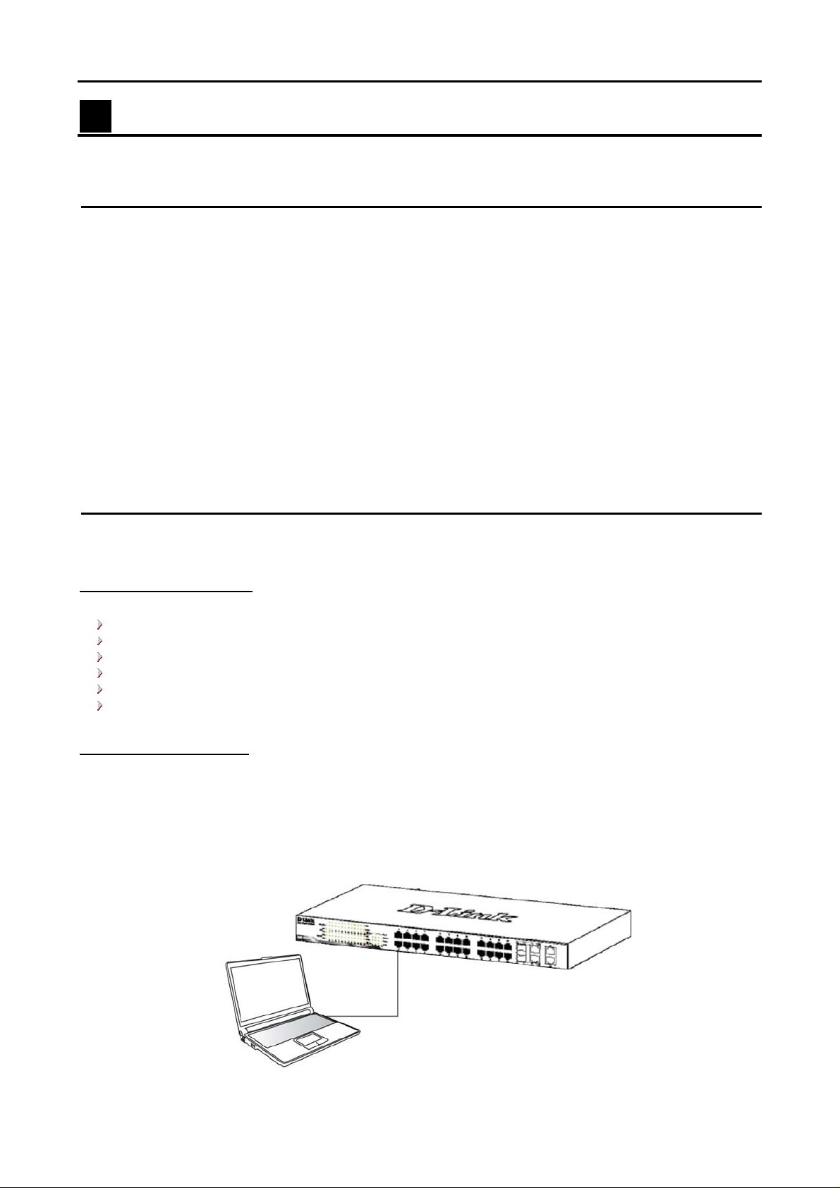
Connecting to the Switch
You need the following equipment to begin the web configuration of your device:
1. A PC with a RJ-45 Ethernet connection
2. A standard Ethernet cable
Connect the Ethernet cable to any of the ports on the front panel of the switch and to the Ethernet port on the
PC.
Figure 5 –Connected Ethernet cable
44
2 Getting Started D-Link Web Smart Switch User Manual
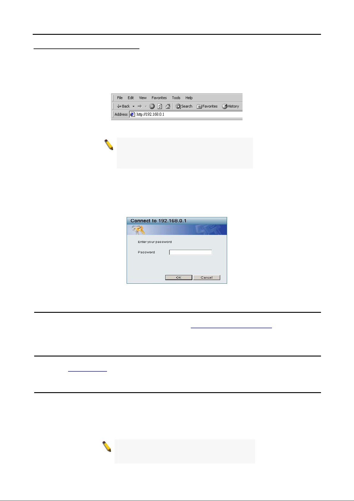
Login Web-based Management Utility
In order to login and configure the switch via an Ethernet connection, the PC must have an IP address in the
same subnet as the switch. For example, if the switch has an IP address of 192.168.0.1, the PC should have
an IP address of 192.168.0.x (where x is a number between 2 and 254), and a subnet mask of
255.255.255.0. There are two ways to login the Web-based Management Utility, you may click the Web
Access button at the top of the SmartConsole Utility or open your web browser and enter 192.168.0.1 (the
factory-default IP address) in the address box. Then press <Enter>
Figure 6 –Enter the IP address 192.168.0.1 in the web browser
NOTE: The switch’s factory default IP address is
192.168.0.1 with a subnet mask of
255.255.255.0 and a default gateway of
192.168.0.254.
The web configuration can also be accessed through the SmartConsole Utility. Open the SmartConsole
Utility and double-click the switch as it appears in the Monitor List. This will automatically load the web
configuration in your web browser.
When the following login box appears, enter the password then press OK to entering the Web-based
Management Utility. The default password is Admin.
Figure 7 – Log in screen
Smart Wizard
Before entering the Web-based Management Utility, When The Smart Wizard will guide you to quick
configure the D-Link Web Smart Switch. Please refer to Samrt Wizard Configuration
configurations.
section for detail
Web-based Management Utility
After clicking the Exit button in Smart Wizard, you will enter the Web-based Management Utility. Please refer
to Chapter 5 Configuration for detail configurations.
SmartConsole Utility
The SmartConsole Utility included on the installation CD is a program for discovering Smart Switches with
the same L2 network segment connected to your PC. This tool is only for computers running Windows 2000,
Windows XP, and Windows Vista x64/86 operating systems. There are two options for the installation of
SmartConsole Utility, one is through the autorun program on the installation CD and the other is manual
installation.
NOTE: Please be sure to remove any existing
SmartConsole Utility from your PC before
installing the latest SmartConsole Utility.
5

2 Getting Started D-Link Web Smart Switch User Manual
Option 1: Follow these steps to install the SmartConsole Utility via the autorun program on the installation
CD.
1. Insert the Utility CD into your CD-Rom Drive.
2. The autorun program will pop up autom atically
3. Simply click on the ”Install SmartConsole Utility” button and an installation wizard will guide you through
the process.
4. After successfully installing the SmartConsole Utility, you can open the utility by clicking Start >
Programs > D-Link SmartConsole Utility.
5. Just connect the Smart Switch to the same L2 network segment of your PC and use the SmartConsole
Utility to discover the Smart Switches.
Option 2: Follow these steps to install the SmartConsole Utility manually.
1. Insert the Utility CD into your CD-Rom Drive.
2. From the Start menu on the Windows desktop, choose Run.
3. In the Run dialog box, type D:\D-Link SmartConsole Utility\setup.exe (where D:\ represents the drive
letter of your CD-Rom) and click OK.
4. Follow the on-screen instruction s to install the utility.
5. Upon completion, go to Start > Programs > D-Link SmartConsole Utility and open the SmartConsole
Utility.
6. Just connect the Smart Switch to the same L2 network segment of your PC and use the SmartConsole
Utility to discover the Smart Switches.
For a detailed look at SmartConsole’s functions, please refer to Chapter 4 SmartConsole Utility
66
3 Product Introduction D-Link Web Smart Switch User Manual
3 Product Introduction
Thank you and congratulations on your purchase of D-Link Web Smart Switch Products.
D-Link’s next generation Web Smart Gigabit switch series blends plug-and-play simplicity with exceptional
performance and reliability for small and medium-sized business (SMB) networking. All models are housed in
a new style rack-mount metal case with easy-to-view front panel diagnostic LEDs, and provide advance
features including up to two or four combo SFP fiber connections, network security, traffic segmentation,
QoS and versatile management. Some of the advanced features include:
A Switch for Each Business Size: With three models (16, 24 and 48) Gigabit ports to choose from, this
series provides flexible choices for different network size requirements. Since Gigabit copper ports capable
of connecting to your existing Cat.5 twisted-pair
reconfiguration process. In addition supports auto-detection of MDI/MDIX, bringing inexpensive and easy
Gigabit connection to the desktops. Each switch provides two or four combo SFP slots for flexible connection
to a fiber backbone or servers. All the SFP slots support 100M and 1000M dual speed fiber connections.
Extensive Layer 2 Features: Implemented as complete L2 devices, these switches include functions such
as Jumbo frame support, IGMP snooping, port mirroring, Spanning Tree, port trunks. The IEEE 802.3x flow
control function allows your servers to directly connect to the switch for fast, reliable data transfer.
Traffic Segmentation and QoS: The switches support 802.1Q VLAN standard tagging by prioritizing traffic
and
to enhance network security
bandwidth-sensitive applications such as streaming multimedia and VoIP in network. These functions allow
switches to work seamlessly with VLAN and 802.1p traffic in network. Asymmetric VLAN is implemented in
these switches for a more efficient use of shared resources such as server or gateway devices.
Network Security: D-Link’s innovative Safeguard Engine function protects the switches against traffic
flooding caused by virus attacks. Additional features like MAC address filters screen access to the network.
They support 802.1X port-based authentication, allowing network to be configured with external RADIUS
servers.
Versatile Management: The new generation of Gigabit web smart switches provides growing businesses
simple and easy management of
management interface that allows administrators to remotely control their network down to the port level. The
SmartConsole easily allows customers to discover multiple D-Link web smart switches with the same L2
network segment connected to user’s local PC. With this utility, users do not need to change the IP address
of PC and also provides easy initial setting of smart switches. The switches with the same L2 network
segment connected to user’s local PC are displayed on the screen for instant access. It allows extensive
switch configuration setting, and basic configuration of discovered devices such as password change,
firmware upgrade.
In addition, users can also use the built-in MIB browser to poll the switches for information about their status
end traps of abnormal events. MIB support allows users to integrate the switches with third-party
s
and
devices for management in an SNMP environment.
performance. Also support 802.1p priority queues, enabling users to run
eir network using an intuitive SmartConsole utility or a Web-Based
th
cable,
these switches eliminate the need of a complex
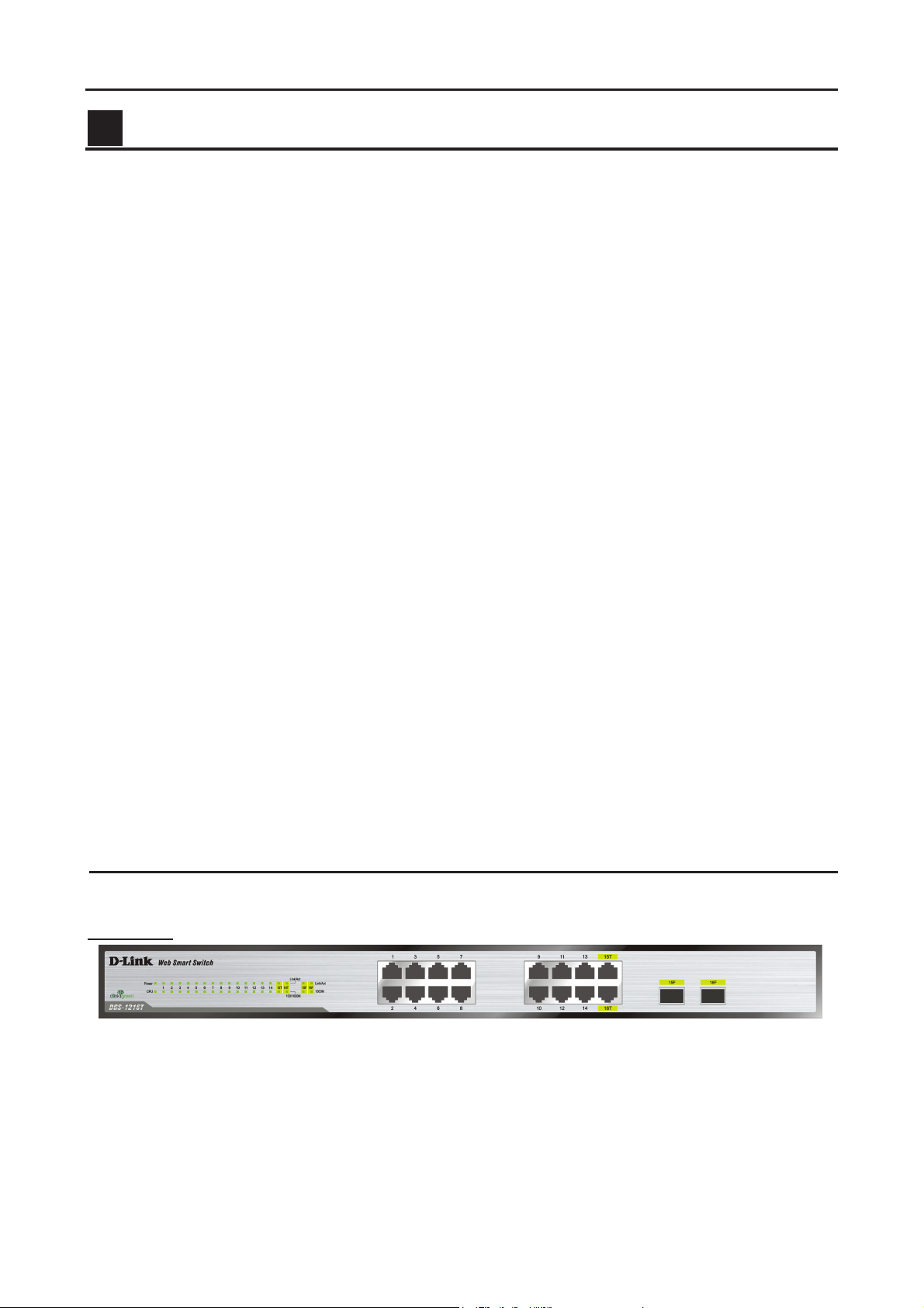
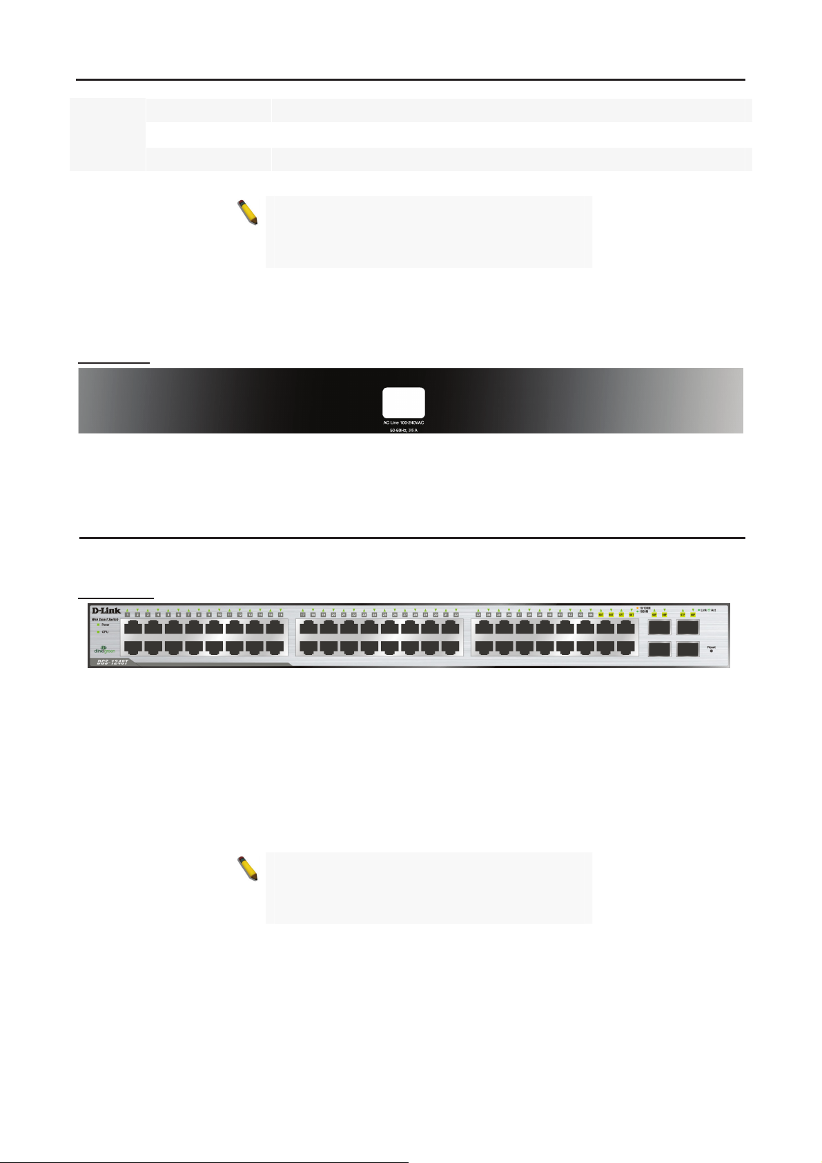
DGS-1216T
16 Port 10/100/1000BaseT with 2 Combo SFP Smart Switch
Front Panel
Power LED: The Power LED flashes when the Switch is connected to a power source.
CPU LED: When the CPU LED is blinking, then the switch is in the normal condition. If the CPU LED is off or
stays in solid light state that means the system might have crashed or firmware upgrade has failed.
Port Link/Act LED (1-14, 15T/F, 16T/F): The Link/Act LED flashes which indicates a network link through
the corresponding port. Blinking state indicates that the Switch is either sending or receiving data to the port.
Figure 8 – DGS-1216T Front Panel
7
3 Product Introduction D-Link Web Smart Switch User Manual
NOTE: On DGS-1216T, the MiniGBIC ports 15F
and 16F are shared with normal RJ-45 ports 15T
and 16T. When MiniGBIC port is used, the RJ-45
port cannot be used.
100/1000M LED (1-14, 15T, 16T): A steady green light denotes a valid 1000Mbps link on the corresponding
port, a steady orange light denotes a valid 10 or 100Mbps link on the port. These LEDs will remain dark if
there is no link/activity on the port.
1000M LED (15F, 16F): The 1000M LED sign lights up when the corresponding port is running on 1000Mbps.
These LEDs will remain dark if there is no link/activity on the port.
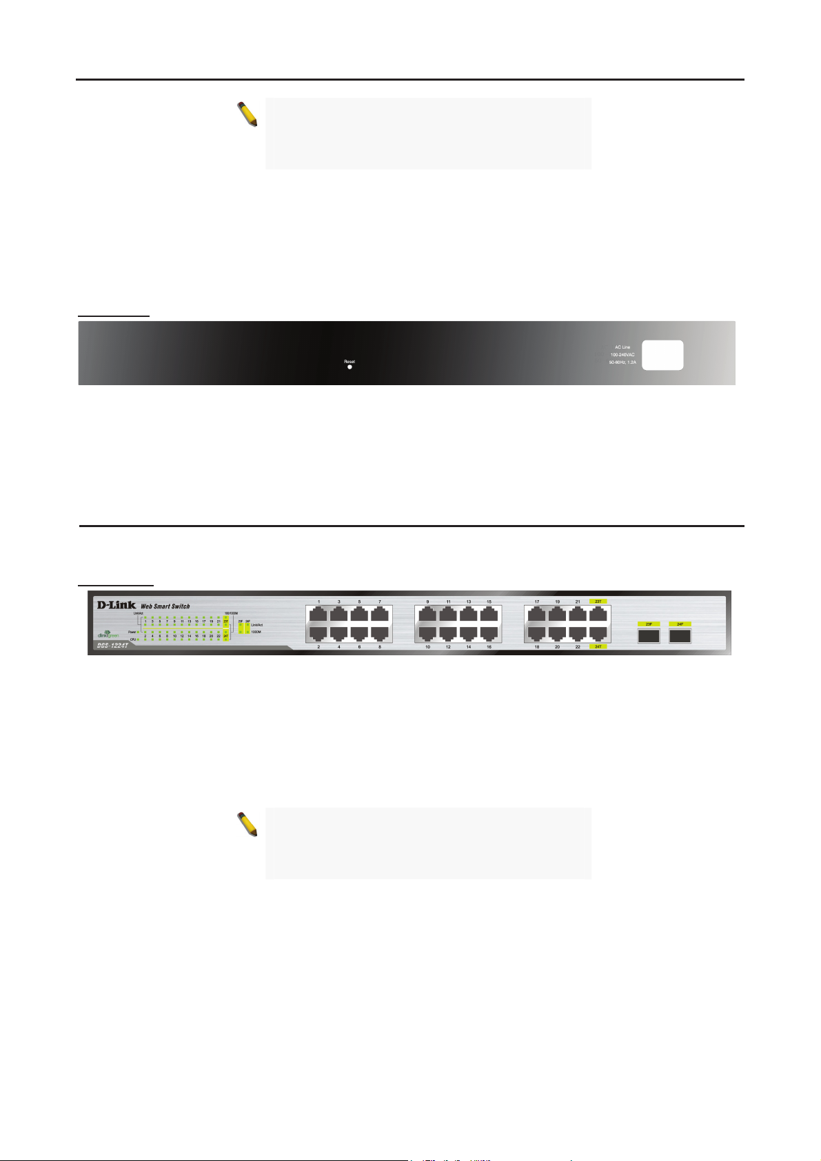
Rear Panel
Reset: By pressing the Reset button the Switch will change back to the default configuration and all changes
will be lost.
Power: The power port is where to connect the AC power cord.
Figure 9 – DGS-1216T Rear Panel
DGS-1224T
24 Port 10/100/1000BaseT with 2 Combo SFP Smart Switch
Front Panel
Power LED: The Power LED flashes when the Switch is connected to a power source.
CPU LED: When the CPU LED is blinking, then the switch is in the normal condition. If the CPU LED is off or
stays in solid light state that means the system might have crashed or firmware upgrade has failed.
Port Link/Act LED (1-22, 23T/F, 24T/F): The Link/Act LED flashes which indicates a network link through
the corresponding port. Blinking state indicates that the Switch is either sending or receiving data to the port.
100/1000M LED (1-22, 23T, 24T): The 100/1000M LED lights up in steady green denotes a valid 1000Mbps
link on the corresponding port, a steady orange light denotes a valid 10 or 100Mbps link on the port. These
LEDs will remain dark if there is no link/activity on the port.
1000M LED (23F, 24F): The 1000M LED sign lights up when the corresponding port is running on 1000Mbps.
These LEDs will remain dark if there is no link/activity on the port.
Figure 10 – DGS-1224T Front Panel
NOTE: On DGS-1224T, the MiniGBIC ports 23F
and 24F are shared with normal RJ-45 ports 23T
and 24T. When MiniGBIC port is used, the RJ-45
port cannot be used.
88

3 Product Introduction D-Link Web Smart Switch User Manual
Rear Panel
Figure 11 – DGS-1224T Rear Panel
Reset: By pressing the Reset button the Switch will change back to the default configuration and all changes
will be lost.
Power: The power port is where to connect the AC power cord.
DGS-1224TP
24 Port 10/100/1000BaseT PoE with 4 Combo SFP Smart Switch
Front Panel
Power LED: The Power LED flashes when the Switch is connected to a power source.
Power Max LED: The Power Max lights up when the system power resource remain ≦15.4W, in the
meantime, system will not provide power to the additional PoE PD inserted.
CPU LED: When the CPU LED is blinking, then the switch is in the normal condition. If the CPU LED is off or
stays in solid light state that means the system might have crashed or firmware upgrade has failed.
Fan Error LED: The FAN LED shows the status of the fans, light off indicates all fans work fine and the red
light indicates that one or multiple fans are working abnormally.
Mode Button: To select the mode of port LED, the Link/Act and PoE LED under the mode button will solid
green to indicate which mode is selected.
LED (1-20, 21T~24T): The port LED will indicate Link/Act or PoE status of this port depending on the
Port
LED mode you selected:
Figure 12 – DGS-1224TP Front Panel
Mode Color Status
Link/Act
Off The corresponding port is link down
Solid Green The corresponding port is link up at 1000Mbps
Blinking Green Data is sending or receiving on corresponding port at 1000Mbps
Solid Orange The corresponding port is link up at 10Mbps or 100Mbps
Blinking Orange Data is sending or receiving on corresponding port at 10Mbps or 100Mbps
PoE
Off No power feeding or no PD found on corresponding port
Solid Green The corresponding port is providing standard 48V power to the PD
Solid Orange PoE error has occurred at this port. You may check the detailed information
for the errors on the PoE Port Setting
Utility.
Port LED (21F~24F): The port LED will indicate Link/Act of this port:
Mode Color Status
Off The corresponding port is link down Link/Act
Solid Green The corresponding port is link up at 1000Mbps
9
page in Web-based Management
3 Product Introduction D-Link Web Smart Switch User Manual
Blinking Green Data is sending or receiving on corresponding port at 1000Mbps
Solid Orange The corresponding port is link up at 100Mbps
Blinking Orange Data is sending or receiving on corresponding port at 100Mbps
NOTE: On DGS-1224TP, the MiniGBIC ports 21F
to 24F are shared with normal RJ-45 ports 21T to
24T. When MiniGBIC port is used, the RJ-45 port
cannot be used.
Reset: By pressing the Reset button the Switch will change back to the default configuration and all changes
will be lost.
Rear Panel
Power: The power port is where to connect the AC power cord.
Figure 13 – DGS-1224TP Rear Panel
DGS-1248T
48 Port 10/100/1000BaseT with 4 Combo SFP Smart Switch
Front Panel
Power LED: The Power LED flashes when the Switch is connected to a power source.
CPU LED: When the CPU LED is blinking, then the switch is in the normal condition. If the CPU LED is off or
stays in solid light state that means the system might have crashed or firmware upgrade has failed.
Port LED (1-44, 45-48T/F): The port LED lights up in steady green denotes a valid 1000Mbps link on the
port, and blinking green light indicates activity on the port (at 1000Mbps). A steady orange light denotes a
valid 10 or 100Mbps link on the port while a blinking orange light indicates activity on the port (at 100Mbps).
These LEDs will remain dark if there is no link/activity on the port.
Figure 14 – DGS-1248T Front Panel
NOTE: On DGS-1248T, the MiniGBIC ports 45F to
48F are shared with normal RJ-45 ports 45T to
48T. When MiniGBIC port is used, the RJ-45 port
cannot be used.
Reset: By pressing the Reset button the Switch will change back to the default configuration and all changes
will be lost.
1100

3 Product Introduction D-Link Web Smart Switch User Manual
Rear Panel
Figure 15 – DGS-1248T Rear Panel
Power: The power port is where to connect the AC power cord.
11
4 SmartConsole Utility D-Link Web Smart Switch User Manual
4 SmartConsole Utility
D-Link SmartConsole Utility allows the administrator to quickly discover all D-Link smart switches which are
in the same domain the PC, collect traps and log messages, and quick access to some basic configurations
of the switch.
The SmartConsole Utility is divided into three parts, Device Configurations at the top, Device List, and
SmartConsole Settings at the left.
Figure 16 – SmartConsole Utility
SmartConsole Settings
The SmartConsole Settings at the left has five icons, Utility Settings, Log, Trap, File, and Help.
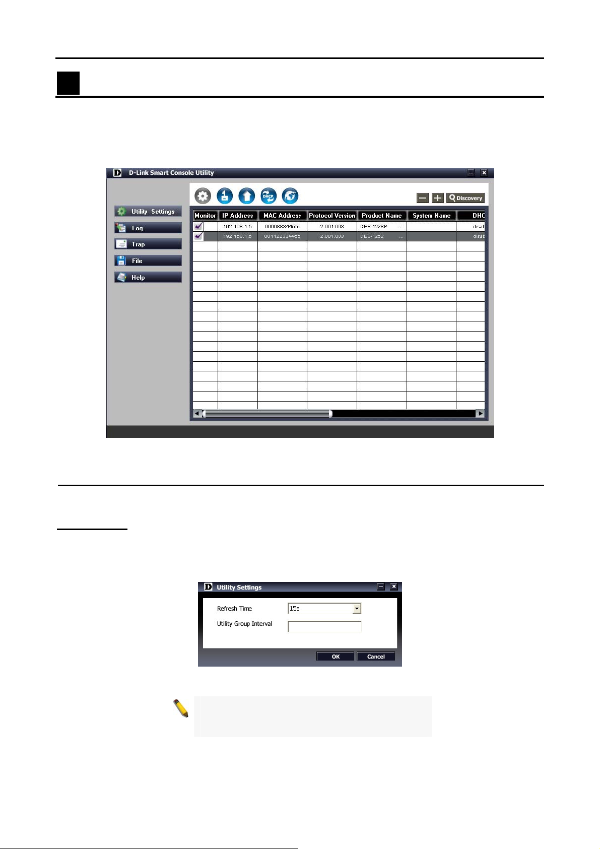
Utility Settings
By clicking on this icon the Utility Settings window will pop up. Refresh time refreshes the devices which
were selected as monitored device in the Device List. Choices include 15 secs, 30 secs, 1mins, 2mins and
5 mins for selecting the monitoring time intervals. Utility Group Interval establishes the intervals (in
seconds) that the Switch will be discovered in the SmartConsole Device List.
Figure 17 – SmartConsole Utility Settings
NOTE: If the Group Interval is set to 0, IGMP
snooping must be disabled or the Web-Smart
Switch will not be discovered.
1122
Loading…
Хорошее руководство по эксплуатации
Законодательство обязывает продавца передать покупателю, вместе с товаром, руководство по эксплуатации D-Link DGS-1216T. Отсутствие инструкции либо неправильная информация, переданная потребителю, составляют основание для рекламации в связи с несоответствием устройства с договором. В законодательстве допускается предоставлении руководства в другой, чем бумажная форме, что, в последнее время, часто используется, предоставляя графическую или электронную форму инструкции D-Link DGS-1216T или обучающее видео для пользователей. Условием остается четкая и понятная форма.
Что такое руководство?
Слово происходит от латинского «instructio», тоесть привести в порядок. Следовательно в инструкции D-Link DGS-1216T можно найти описание этапов поведения. Цель инструкции заключается в облегчении запуска, использования оборудования либо выполнения определенной деятельности. Инструкция является набором информации о предмете/услуге, подсказкой.
К сожалению немного пользователей находит время для чтения инструкций D-Link DGS-1216T, и хорошая инструкция позволяет не только узнать ряд дополнительных функций приобретенного устройства, но и позволяет избежать возникновения большинства поломок.
Из чего должно состоять идеальное руководство по эксплуатации?
Прежде всего в инструкции D-Link DGS-1216T должна находится:
— информация относительно технических данных устройства D-Link DGS-1216T
— название производителя и год производства оборудования D-Link DGS-1216T
— правила обслуживания, настройки и ухода за оборудованием D-Link DGS-1216T
— знаки безопасности и сертификаты, подтверждающие соответствие стандартам
Почему мы не читаем инструкций?
Как правило из-за нехватки времени и уверенности в отдельных функциональностях приобретенных устройств. К сожалению само подсоединение и запуск D-Link DGS-1216T это слишком мало. Инструкция заключает ряд отдельных указаний, касающихся функциональности, принципов безопасности, способов ухода (даже то, какие средства стоит использовать), возможных поломок D-Link DGS-1216T и способов решения проблем, возникающих во время использования. И наконец то, в инструкции можно найти адресные данные сайта D-Link, в случае отсутствия эффективности предлагаемых решений. Сейчас очень большой популярностью пользуются инструкции в форме интересных анимаций или видео материалов, которое лучше, чем брошюра воспринимаются пользователем. Такой вид инструкции позволяет пользователю просмотреть весь фильм, не пропуская спецификацию и сложные технические описания D-Link DGS-1216T, как это часто бывает в случае бумажной версии.
Почему стоит читать инструкции?
Прежде всего здесь мы найдем ответы касательно конструкции, возможностей устройства D-Link DGS-1216T, использования отдельных аксессуаров и ряд информации, позволяющей вполне использовать все функции и упрощения.
После удачной покупки оборудования/устройства стоит посвятить несколько минут для ознакомления с каждой частью инструкции D-Link DGS-1216T. Сейчас их старательно готовят или переводят, чтобы они были не только понятными для пользователя, но и чтобы выполняли свою основную информационно-поддерживающую функцию.
Описание
Рекомендованная замена — DGS-1210-16
Коммутаторы серии Web Smart следующего поколения представляют собой экономически эффективное решение для сетей малого и среднего бизнеса (SMB) и обеспечивают надежность и простоту установки, основанную на технологии Plug and Play. Корпус коммутаторов данной серии выполнен в новом стиле с улучшенной панелью индикаторов состояния. Расширенный функционал коммутаторов включает до 4 комбо-портов 1000BASE-T/SFP, функции обеспечения безопасности, сегментации трафика, QoS и гибкое управление.
16 портов Gigabit Ethernet
Коммутатор DGS-1216T оборудован 16 портами Gigabit Ethernet, 2 из которых являются комбо-портами 1000BASE-T/SFP для гибкого подключения к магистрали сети или серверам. Порты на основе витой пары поддерживают автоопределение полярности MDI/MDIX, обеспечивая простоту подключения рабочих станций.
Расширенные функции 2-го уровня
Являясь устройствами 2 уровня, коммутаторы включают в себя такие функции, как поддержка Jumbo-фреймов, IGMP snooping, зеркалирование портов, Spanning Tree и агрегирование портов для повышения производительности и отказоустойчивости сети.
Сегментация трафика и QoS
Коммутаторы поддерживают протокол 802.1Q VLAN Tagging для сегментации трафика по группам для повышения безопасности и производительности сети. Они также поддерживают очереди приоритетов 802.1p, позволяя пользователям использовать в сети чувствительные к задержкам приложения, такие как потоковое аудио и видео, и VoIP. Эти функции позволяют коммутаторам работать в сетях с применением VLAN и 802.1p..
Сетевая безопасность
Коммутаторы поддерживают статическую таблицу МАС-адресов для ограничения доступа к сети. Аутентификация 802.1x на основе портов, позволяет использовать внешний RADIUS-сервер для авторизации пользователей. Дополнительные функции, такие как D-Link Safeguard Engine защищают коммутатор от вредоносного трафика, вызванного активностью вирусов/червей.
Гибкое управление
Коммутатор настраивается и управляется через утилиту SmartConsole или Web-интерфейс. SmartConsole обеспечивает простой доступ с локального ПК к коммутатору, при этом пользователям не требуется вводить IP-адрес и маску подсети. Кроме того, все доступные коммутаторы сети будут отображены на одном экране утилиты. Web-интерфейс позволяет получить доступ к коммутатору из любого места сети или удаленно с помощью Web-браузера. Это позволяет повсеместно настраивать конфигурацию коммутатора, а также сохранять конфигурационный файл для его дублирования на других коммутаторах.
Кроме того, пользователи могут использовать встроенные MIB для опроса состояния коммутатора и для отсылки сообщений о нештатных событиях. Поддержка MIB позволяет пользователям интегрировать коммутаторы с другими устройствами сторонних производителей в единую среду SNMP-управления.
Характеристики
-
Общие
- IEEE 802.3 10BASE-T Ethernet (медный кабель на витой паре)
- IEEE 802.3u 100BASE-TX Fast Ethernet (медный кабель на витой паре)
- IEEE 802.3ab 1000BASE-T Gigabit Ethernet (медный кабель на витой паре)
- IEEE 802.3z Gigabit Ethernet (оптоволоконный кабель)
- Автосогласование ANSI/IEEE 802.3 NWay
- Управление потоком 802.3х
- Зеркалирование портов
Количество портов
- 14 портов 10/100/1000BASE-T
- 2 комбо-порта 10/100/1000BASE-T/SFP
При использовании SFP соответствующие порты 10/100/1000 BASE-T блокируются
Протокол
CSMA/CD
Скорость передачи данных
- Ethernet:
10 Мбит/с (полудуплексный режим)
20 Мбит/с (полнодуплексный режим) - Fast Ethernet:
100 Мбит/с (полудуплексный режим)
200 Мбит/с (полнодуплексный режим) - Gigabit Ethernet:
2000 Мбит/с (полнодуплексный режим)Топология сети
- UTP Cat. 5, Cat. 5e (100 м макс.)
- EIA/TIA-568 100-Ом STP (100 м макс.)
Полный/полу дуплекс
- Полный/полу дуплекс для скорости 10/100 Мбит/с
- Полный дуплекс для скорости Gigabit
Интерфейс обмена данными
Автоопределение MDI/MDIX для всех портов на витой паре
Индикаторы
- Power/CPU (для устройства)
- Link/Act, 100Mbps , 1000Mbps (для порта 10/100/1000BASE-T)
- Link/Act, 1000Mbps (для слота SFP)
Программное обеспечение
Функции 2 уровня
- IGMP snooping: поддержка 64 многоадресных групп (Multicast Groups)
- Default flooding для портов не подключившихся к многоадресной группе
- 802.1D Spanning Tree
Агрегирование портов: до 6 групп на устройство, до 8 портов на группуVLAN
- Стандарт 802.1Q VLAN (VLAN Tagging)
- До 256 статических групп VLAN
QoS (Качество обслуживания)
- Стандарт очередей приоритетов 802.1p
- До 4 очередей для каждого порта
- Поддержка метода WRR для обработки очередей
Безопасность
- Управление доступом 802.1x на основе портов
- Управление широкополосным штормом: пороговая величина 8 Кб, 16 Кб, 32K, 64 Кб, 128 Кб, 512 Кб, 1024 Кб, 2048 Кб, 4096 Кб в секунду
- D-Link Safeguard Engine для защиты CPU от широковещательной/многоадресной/одноадресной рассылки
Управление
- Web-интерфейс или утилита SmartConsole
- Поддержка SNMP
- DHCP-клиент
- Настройка прерываний для IP-адреса назначения, системных событий, событий порта на оптоволокне, событий порта на витой паре
- Управление доступом к порту
- Настройка резервного копирования/восстановления на основе Web-интерфейса
- Настройка резервного копирования/восстановления программного обеспечения на основе Web-интерфейса
- Обновление программного обеспечения с помощью утилиты SmartConsole
- Перезагрузка
MIB
- RFC 1213 MIB-II
- D-Link Enterprise Private MIB
Производительность
Пропускная способность коммутатора
32 Гбит/с
Метод коммутации
Store-and-forward
Таблица MAC-адресов
8 Кб записей на устройство
Изучение MAC-адресов
- До 256 статических записей MAC-адресов
- Включение/отключение автоизучения MAC-адресов
Фильтрация пакетов/Скорость передачи (полудуплексный режим)
Максимум 1,488,095 pps для каждого порта
Буфер RAM
512 Кб на устройство
Jumbo-фреймы
10 240 байт
Стандарты порта и функции
Сертификаты
Заказ
Настраиваемый коммутатор Gigabit Ethernet
DGS-1216T 16 портов 10/100/1000BASE-T , 2 комбо SFP (Mini GBIC)
Дополнительные мини GBIC SFP трансиверы
DEM-310GT SFP трансивер для 1000BASE-LX, одномодовый кабель, макс. расстояние 10 км, 3.3В
DEM-311GT SFP трансивер для 1000BASE-SX, многомодовый кабель, макс. расстояние 550 м, 3.3В
DEM-314GT SFP трансивер для 1000BASE-LHX, одномодовый кабель, макс. расстояние 40 км, 3.3В
DEM-315GT SFP трансивер для 1000BASE-ZX, одномодовый кабель, макс. расстояние 80 км, 3.3В
Изображения
DGS-1216T
Вид спередиВид сзади
Загрузки
Общее описание
Обновления от 19.05.2008
Обновления от 25.04.2008
Обновления от 01.02.2006
Обновления от 29.11.2004
SNMP от 13.02.2008
SNMP от 27.09.2006
SNMP от 01.02.2006
Руководство пользователя для ревизии D
Руководство пользователя для ревизии B
Руководство пользователя для ревизии С
Руководство пользователя для ревизии A
Краткое руководство по установке для ревизии B
Мы предлагаем следующие способы доставки товара:
Самовывоз из пункта выдачи
Самостоятельное получение заказа в пункте выдачи. Дата и время получения заранее согласуется с менеджером магазина.
Отгрузка товара юридическим лицам осуществляется только при наличии печати или правильно оформленной и заполненной доверенности, наличии паспорта получателя.
Курьерская доставка по Москве
Доставка по адресу покупателя или до пункта приема транспортной компании в г. Москве. Дата и время доставки заранее согласуется с менеджером магазина.
Доставка транспортной компанией по России
Доставка транспортной компанией по России до пункта выдачи транспортной компании или до конечного адреса покупателя.
Мы предлагаем следующие способы оплаты товара:
Оплата наличными
Оплата за наличный расчет для физических и юридических лиц. После внесения денежных средств Покупатель подписывает товаросопроводительные документы и получает кассовый чек.
Безналичная оплата
Мы работаем с физическими и юридическими лицами за безналичный расчёт со 100% предоплатой с оформлением всех предусмотренных законодательством документов. Счёт на оплату направляется Покупателю на электронную почту после запроса счета через форму на сайте либо по электронной почте. Цена на заказанный товар действительна в течение 2 дней с момента оформления Заказа.
Электронные способы
Оплата Заказа электронными способами, в т.ч. банковскими картами. Оплата Заказа данным способом доступна запросом ссылки на оплату у нашего менеджера.
Если у вас возникнут вопросы по оформлению заказа, вы можете обратиться к нам, позвонив по телефону +7 495 179-33-83 или связавшись по электронной почте sale@ru-dlink.com. Мы гарантируем оперативный ответ на ваш запрос и предоставление наилучших условий от официального поставщика D-LINK.
Запрос цены или КП
Мы предоставляем официальную гарантию на всю продукцию.
Сервис расширенной гарантии включает в себя:
- Приемку в сервисном центра для выполнения диагностики дефекта.
- Ремонт.
- Бесплатную доставку клиенту.
В рамках дополнительной программы оборудование D-LINK может быть поставлено с расширенной гарантией D-LINK. Cрок расширенной гарантии D-LINK – 12 месяцев с даты регистрации партнером продажи данного оборудования в базе данных компании D-LINK. По желанию клиента расширенная гарантия может быть продлена на следующие 12 месяцев по истечению первоначального срока или приобретена сразу на 24 или 36 месяцев.
Контакты гарантийного отдела:
Телефон: +7 495 179-33-83
E-mail: sale@ru-dlink.com
Получить КП / Счет
Для расчета коммерческого предложения или получения счета на поставку оборудования D-LINK оставьте заявку в форме ниже или свяжитесь с отделом продаж по телефону +7 495 179-33-83 или электронной почте sale@ru-dlink.com. Мы гарантируем оперативный ответ на ваш запрос и предоставление наилучших условий от официального поставщика D-LINK.
Специалист по решениям D-LINK:
- Окажет профессиональную консультацию.
- Сообщит вашу цену на продукцию.
- Сообщит информацию об актуальных акциях и скидках.
- Подскажет ближайшее к вам отделение с наличием нужной продукции.
- Согласует с вами возможную дату и время доставки.
Запрос цены или КП