
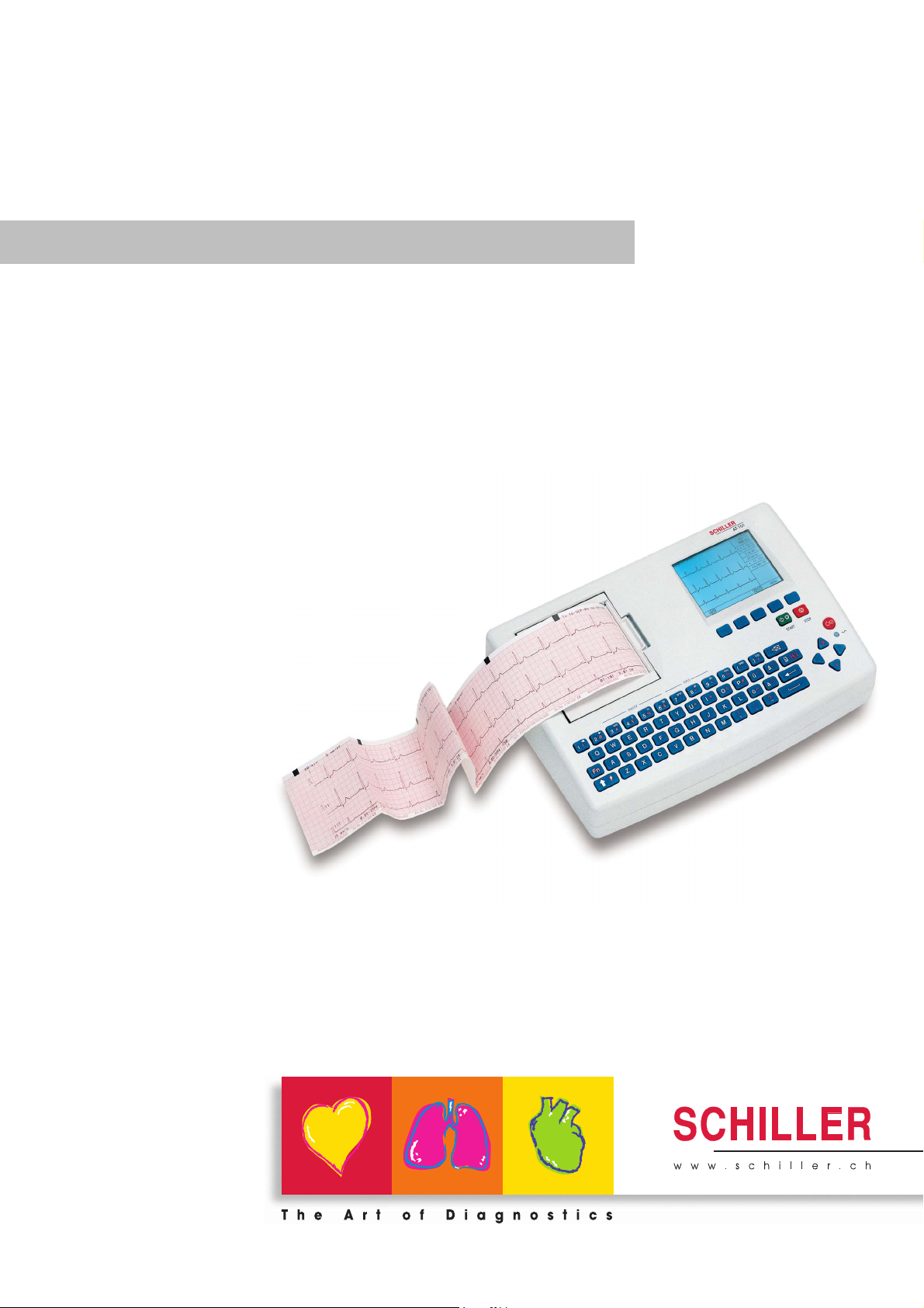
AT-101
AT-101
12-Channel ECG Unit
Art.-no.: 2.510526 Rev.: c *2.510526*
User Guide

Sales and Service Information
The SCHILLER sales and service centre network is world-wide. For the address
of your local distributor, contact your nearest SCHILLER subsidiary. In case of difficulty a complete list of all distributors and subsidiaries is provided on our internet
site: http://www.schiller.ch.
Sales information can also be obtained from:
sales@schiller.ch
Address Headquarters
SCHILLER AG Phone: +41 (0) 41 766 42 42
Altgasse 68 Fax: +41 (0) 41 761 08 80,
CH-6341 Baar, Switzerland E-mail: sales@schiller.ch
Web: www.schiller.ch
Artikel-Nr.: 2.510526 Rev.: c
Issue date: 25.05.05

AT-101
User Guide
Contents
1 Safety notes ……………………………………….3
1.1 Responsibility of the User ………………………………………….. 3
1.2 Intended Use ……………………………………………………………… 3
1.3 Organisational Measures…………………………………………….. 3
1.4 Safety-conscious Operation………………………………………… 4
1.5 Safety Facilities ………………………………………………………….. 4
1.6 Operation with other Devices ………………………………………. 5
1.7 Maintenance……………………………………………………………….. 5
1.8 Safety Symbols and Pictograms………………………………….. 6
1.8.1 Used symbols in this document ………………………………………………… 6
1.8.2 Used symbols on the device …………………………………………………….. 7
1.9 Terms of Warranty………………………………………………………. 8
2 Introduction ……………………………………….9
2.1 Features……………………………………………………………………… 9
2.1.1 Standard Features ………………………………………………………………….. 9
2.1.2 Optional Features……………………………………………………………………. 9
2.2 Operating Philosophy Overview ………………………………… 10
2.2.1 Initiating Functions or Tasks …………………………………………………… 10
2.2.2 Main Components of the AT-101 …………………………………………….. 11
2.2.3 Back Panel…………………………………………………………………………… 11
2.3 Keypad……………………………………………………………………… 12
2.4 LCD Screen ………………………………………………………………. 14
3 Operation ………………………………………… 15
3.1 Start-up and Initial Preparation ………………………………….. 15
3.1.1 Connecting AT-101 ……………………………………………………………….. 15
3.1.2 Battery Operation………………………………………………………………….. 16
3.1.3 Switching ON and OFF ………………………………………………………….. 16
3.1.4 Isolating the Mains Supply ……………………………………………………… 16
3.1.5 Potential Equalisation…………………………………………………………….. 16
3.1.6 Inserting Printing Paper …………………………………………………………. 17
3.1.7 LCD contrast adjustment………………………………………………………… 17
3.2 Entering Patient Data ………………………………………………… 18
4 Resting ECG ……………………………………. 19
4.1 Electrode Placement …………………………………………………. 19
4.2 Further Lead Combinations……………………………………….. 21
4.2.1 Nehb Leads………………………………………………………………………….. 21
4.2.2 Electrode Positions for Additional Leads…………………………………… 22
Art.-no.: 2.510526 Rev.: c
4.2.3 Electrodes and Neutral Electrodes Identification and
Colour Code…………………………………………………………………………. 23
4.3 Skin/Electrode Resistance…………………………………………. 24
4.3.1 High Electrode Resistance Indication ………………………………………. 24
4.3.2 Electrode and Patient cable Check (Lead Test)…………………………. 24
4.4 Modes of Operation and Procedural
Page 1

AT-101
Overview…………………………………………………………………… 25
4.4.1 Automatic Mode……………………………………………………………………. 26
4.4.2 Manual Mode ……………………………………………………………………….. 27
4.4.3 Screen (and Manual Printout) Settings …………………………………….. 28
4.5 Memory (option)………………………………………………………… 30
4.5.1 Transmitting the Recordings…………………………………………………… 31
5 Setup ………………………………………………..32
5.1 Entering the SETUP Menu …………………………………………. 32
5.1.1 Navigating in the Setup Screens……………………………………………… 32
5.2 ECG Settings…………………………………………………………….. 33
5.2.1 Automatic Format 1 and 2 Internal Printer ………………………………… 34
5.2.2 Automatic Format 1 and 2 External Printer……………………………….. 35
5.2.3 Filters ………………………………………………………………………………….. 36
5.2.4 Interpretation (Only with version C) …………………………………………. 37
5.2.5 Leads ………………………………………………………………………………….. 38
5.2.6 General (only with version m = Memory) ………………………………….. 38
5.3 System Settings………………………………………………………… 39
5.3.1 Unit……………………………………………………………………………………… 40
5.3.2 Communication ……………………………………………………………………. 41
5.3.3 Communication with SCM………………………………………………………. 42
5.3.4 Test and Information……………………………………………………………… 43
5.3.4.1 Print Setup …………………………………………………………………………… 44
5.3.4.2 Communications Test ……………………………………………………………. 45
5.3.4.3 Installing New Software Options (Upgrade)………………………………. 45
5.3.4.4 Update the Software ……………………………………………………………… 45
5.3.4.5 Default Settings…………………………………………………………………….. 46
6 Care & Maintenance ………………………….47
6.1 Service interval …………………………………………………………. 47
6.2 Communication (RS-232) Test……………………………………. 47
6.3 Maintenance interval for the battery …………………………… 48
6.3.1 Charging the battery …………………………………………………………….. 48
6.3.2 Battery disposal ……………………………………………………………………. 48
6.4 Changing the fuse and mains voltage ………………………… 49
6.5 Cleaning……………………………………………………………………. 50
6.5.1 Cleaning the Casing………………………………………………………………. 50
6.5.2 Cleaning the Patient Cable …………………………………………………….. 50
6.5.3 Cleaning the Thermal Print Head…………………………………………….. 50
6.6 Replacing the Recording Paper …………………………………. 51
6.6.1 Thermal Paper Handling ………………………………………………………… 51
6.7 Fault-Finding …………………………………………………………….. 52
6.7.1 Accessories and Disposables …………………………………………………. 53
7 Technical Data ………………………………….54
7.1 System ……………………………………………………………………… 54
7.2 Technical Data for ECG……………………………………………… 55
7.3 Safety Standards ………………………………………………………. 56
8 Index ………………………………………………..57
Art.-no.: 2.510526 Rev.: c
Page 2
Safety notes 1
AT-101 User Guide Responsibility of the User 1.1
1 Safety notes
1.1 Responsibility of the User
V This device must only be used by qualified doctors or trained medical personnel.
V The numerical and graphical results and any interpretation given must be exami-
ned with respect to the overall clinical condition of the patient and the general recorded data quality.
V The indications given by this equipment are not a substitute for regular checking
of vital functions.
V Specify the competencies of the personnel for operation and repair.
V Ensure that personnel have read and understood these operating instructions. In
particular this chapter “safety notes» must be read and understood.
V Have damaged or missing components replaced immediately.
V The operator is responsible for compliance with all applicable accident prevention
regulations and safety regulations.
1.2 Intended Use
V The AT-101 is a 12-channel, ECG device used for the recording, analysis and
evaluation of ECG Recordings. Recordings made with the AT-101 can be used
as a diagnostic aid for heart function and heart conditions. The AT-101 is designed for indoor use and can be used for all patients of both sexes, all races, and
all ages.
V There is no danger for patients with pacemaker.
V Only operate the device in accordance with the specified technical data.
V The device is not designed for sterile use nor is it designed for outdoor use.
V Do not use this unit in areas where there is any danger of explosion or in the
presence of flammable gases such as anaesthetic agents.
V This unit is CF classified and defibrillation protected only when the original
patient cable is used. However, as a safety precaution when possible, remove
electrodes before defibrillation.
V This product is not designed for internal use.This product is not designed for di-
rect cardiac application.
1.3 Organisational Measures
V Before using the unit, ensure that an introduction regarding the unit functions and
the safety precautions has been provided by a medical product representative.
V Keep these operating instructions in an accessible place for reference when re-
quired. Make sure that they are always complete and legible.
V Observe the operating instructions and maintenance instructions.
V These operating instructions do not override any statutory or local regulations, or
Art.-no.: 2.510526 Rev.: c
procedures for the prevention of accidents and environmental protection.
Page 3
1 Safety notes
1.4 Safety-conscious Operation
1.4 Safety-conscious Operation
1.5 Safety Facilities
AT-101
V Make sure that the staff has read and understood the operating instructions — par-
ticularly the «Safety Notes» chapter.
V Do not touch the unit casing during defibrillation.
V To ensure patient safety, none of the electrodes including the neutral electrode,
nor the patient or any person with simultaneous patient contact, must come in
contact with conductive parts, even when these are earthed.
V Immediately report any changes that impair safety (including operating beha-
viour) to the person responsible.
V Do not place any liquids on the unit. If liquid should be spilled over the device,
immediately disconnect the device from the mains and wipe it. The device must
be serviced before reusing.
V Only connect the original SCHILLER patient cable to the patient socket.
V Operating the device without the correctly rated fuse, or with defective cables,
constitutes a danger to life. Therefore:
– Do not operate the unit if the earth connection is suspect or if the mains lead is
damaged or suspected of being damaged.
– Damaged cable connections and connectors must be replaced
immediately.
– The electrical safety devices, such as fuses, must not be altered.
– Ruptured fuses must only be replaced with the same type and rating as the ori-
ginal.
Page 4
Art.-no.: 2.510526 Rev.: c
Safety notes 1
AT-101 User Guide Operation with other Devices 1.6
1.6 Operation with other Devices
V Use only accessories and other parts recommended or supplied by SCHILLER
AG. Use of other than recommended or supplied parts may result in injury, inaccurate information and/or damage to the unit.
V Ancillary equipment connected to the analogue and/or digital interfaces must be
certified according to the respective IEC standards (e.g. IEC/EN 60950 for data
processing equipment and IEC/EN 60601-1 for medical equipment). Furthermore
all configurations shall comply with the valid version of the system standard IEC/
EN 60601-1-1. Everybody who connects additional equipment to the signal input
part or signal output part configures a medical system, and is therefore responsible that the system complies with the requirements of the valid version of the system standard IEC/EN 60601-1-1. If in doubt, consult the technical service department or your local representative.
– EC/EN 60601-1-1 states that the patient must remain at least 1.5 meters clear
of the unit. If this is not possible, a safety isolating transformer must be installed.
V Any other equipment used with the patient must use the same common earth as
the AT-101.
V Precautions must be observed when using high frequency devices. Use the spe-
cial high frequency SCHILLER patient cable to avoid possible signal interference
during ECG acquisition.
V There is no danger when using the ECG unit simultaneously with electrical stimu-
lation equipment. However, the stimulation units should only be used at a sufficient distance from the electrodes. If in doubt, the patient should be disconnected from the device.
V If the patient cable should become defective after defibrillation, an electrode be-
comes displaced, or an electrode resistance is too high, a lead-off indication is
displayed in the upper right part of the screen and an acoustic alarm given.
V If the device is a part of a medical system, the original SCHILLER patient cable
must only be used with, and connected to, the patient connector on the AT-101.
1.7 Maintenance
V Danger of electric shock! Do not open the device. No serviceable parts inside.
Refer servicing to qualified technician authorised by SCHILLER only.
V Before cleaning and to isolate the mains power supply, switch the unit off and dis-
connect it from the mains by removing the plug.
V Do not use high temperature sterilisation processes
(such as autoclaving). Do not use E-beam or gamma radiation sterilisation.
V Do not use solvent or abrasive cleaners on either the unit or cable assemblies.
V Do not, under any circumstances, immerse the unit or cable assemblies in liquid.
Art.-no.: 2.510526 Rev.: c
Page 5
1 Safety notes
1.8 Safety Symbols and Pictograms
1.8 Safety Symbols and Pictograms
1.8.1 Used symbols in this document
AT-101
The safety level is classified according ANSI Z535.4. The following overview shows
the used safety symbols and pictograms used in this manual.
For a direct danger which could lead to severe personal injury or to death.
For a possibly dangerous situation, which could lead to heavy bodily injury or to death.
For a possibly dangerous situation which could lead to personal injury. This symbol is
also used to indicate possible damage to property.
For general safety notes as listed in this chapter.
Used for electrical dangers, warnings and other notes in regarding operation with electricity.
Note For possibly dangerous situations, which could lead to damages to property or
system failure. Important or helpful user information
Reference to other guidelines
Page 6
Art.-no.: 2.510526 Rev.: c
Safety notes 1
AT-101 User Guide Safety Symbols and Pictograms 1.8
1.8.2 Used symbols on the device
Potential equalization
CF symbol. This unit is classified safe for internal and external use. However, It is only
defibrillation protected when used with the original SCHILLER patient cable!
Inappropriate disposal can lead to environmental pollution.
Units/components and accessories no longer required can be returned to SCHILLER
AG for disposal. Alternatively, the unit should be disposed of in a municipally approved recycling centre.
Notified body of the CE certification (TÜV P.S.)
Attention: Consult accompanying documents.
Art.-no.: 2.510526 Rev.: c
Page 7

1 Safety notes
1.9 Terms of Warranty
AT-101
1.9 Terms of Warranty
The SCHILLER AT-101 is warranted against defects in material and manufacture for
the duration of one year (as from date of purchase). Excluded from this guarantee is
damage caused by an accident or as a result of improper handling. The warranty entitles free replacement of the defective part. Any liability for subsequent damage is excluded. The warranty is void if unauthorized or unqualified persons attempt to make
repairs.
In case of a defect, send the apparatus to your dealer or directly to the manufacturer.
The manufacturer can only be held responsible for the safety, reliability, and performance of the apparatus if:
• assembly operations, extensions, readjustments, modifications, or repairs are carried out by persons authorized by him, and
• the SCHILLER AT-101 and approved attached equipment is used in accordance
with the manufacturers instructions.
There are no Express or implied warranties which extend beyond the warranties hereinabove set forth. SCHILLER makes no warranty of merchantability or fitness for a
particulare purpose with respect to the product or parts therefof.
This equipment has been tested and found to comply with the limits for a class A digital device, pursuant to both Part 15 of the FCC (Federal Communications Commission) Rules and the radio interference regulations of the Canadian Department of
Communications. These limits are designed to provide reasonable protection against
harmful interference when the equipment is operated in a commercial environment.
This equipment generates, uses and can radiate radio frequency energy and, if not
installed and used in accordance with this instruction manual, may cause harmful interference to radio communications. Operation of this equipment in a residential area
is likely to cause harmful interference in which case the user will be required to correct
the interference at his own expense.
Page 8
Art.-no.: 2.510526 Rev.: c

Introduction 2
AT-101 User Guide Features 2.1
2 Introduction
2.1 Features
The SCHILLER AT-101 is a 12-channel ECG unit designed to record, display, and
analyse resting ECGs. The unit has been extensively researched to give an ergonomic, clear interface that‘s easy to use without compromising functionality. The AT-101
has the following features:
2.1.1 Standard Features
• Alphanumeric keypad and dedicated soft key interface for easy, user friendly
operation.
• Integral thermal quality printer with various user defined print format
options.
• Measurements and average cycles with automatic and manual printout of the recording.
2.1.2 Optional Features
• External printers
• ECG Interpretation
• Memory for up to 40 recordings
• Thrombolysis
• SCHILLER Communication modul (SCM) for data transmission to server via:
– Ethernet
– Modem (option)
Art.-no.: 2.510526 Rev.: c
Page 9

2 Introduction
2.2 Operating Philosophy Overview
2.2 Operating Philosophy Overview
AT-101
There are broadly four types of data display as follows:
Data Acquisition and ECG
Recording Screen
In this screen the real-time ECG is displayed. From this screen a continuous printout
can be initiated and/or an auto recording can be made. In auto mode 10 seconds of
ECG data is analysed and averaged and the results given on a printout. The format
and data of an auto mode printout is independent of the screen display, and is defined
in the setup screens. (See paragraph 5.2 page 34).
An auto mode recording can also be stored in the memory for later print or
transmission.
Memory Screen In this screen stored recordings can be accessed, printed and transmitted.
Patient Data Screen Patient data entry via the keypad.
Data Entry and Setup In these screens all system settings are made.
2.2.1 Initiating Functions or Tasks
Most functions and tasks are initiated by the 5 softkeys (1) situated immediately below
the LCD. The function of the softkeys varies according to the screen displayed and is
displayed on the LCD immediately above the key itself.
During data acquisition, further dedicated function keys are provided to make an auto
mode recording (START) and to stop a manual printout (STOP). The top line of the
alphanumeric keypad, additionally enables direct settings of lead group, trace speed
and sensitivity, filter on/off and other functions, for both the real-time display and
(manual) printout.
LEAD
TEST
1
Fig. 2.1 Start-up screen
MANUAL
HR:
78 / min
FILTER OFF
MENU
Art.-no.: 2.510526 Rev.: c
Page 10

Introduction 2
AT-101 User Guide Operating Philosophy Overview 2.2
2.2.2 Main Components of the AT-101
(1) LCD Display
(2) Softkey control
(3) Keypad and dedicated function keys
(4) Printer
1
2
3
4
2.2.3 Back Panel
V All externally connected hardware must be approved by SCHILLER. Connection
of any hardware not approved by SCHILLER is at the owner‘s risk. The unit guarantee may also be invalid. See also safety note paragraph 1.6.
(1) Patient cable connector
(2) LPT connector for the connection of an external printer
(3) RS-232 for connection of a modem or a PC for export of stored recordings
(4) Mains connector (with fuse above)
(5) RJ11 Modem connector with SCM (option)
(6) Potential equalisation stud
(7) RJ45 connector for Ethernet with SCM (option)
2
Art.-no.: 2.510526 Rev.: c
1
3
4
5
6
7
Page 11

2 Introduction
2.3 Keypad
2.3 Keypad
HR:
78 / min
FILTER OFF
AT-101
LEAD
TEST
2
MANUAL
MENU
3
1
(1) Softkeys — the function of these keys changes depending on the screen display-
ed. The function of these keys is shown on the screen above the keys. If nothing
is written above a softkey, it has no function for the current screen.
(2) Auto Mode recording (in Auto mode 1). Press the SHIFT followed by the START
key (2) for auto mode 2.
(3) STOP printout
Page 12
Art.-no.: 2.510526 Rev.: c

17
Introduction 2
AT-101 User Guide Keypad 2.3
4 5 6 7 8 9 10 11 12 13
16
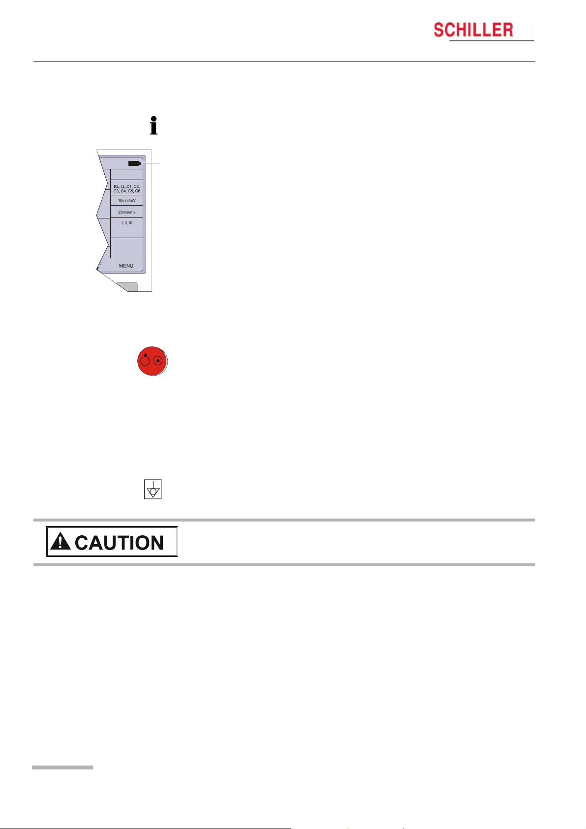
(4) The top figures on the number keys ‘1‘and ‘2‘(designated < and >), change the
lead group displayed on the screen, forward and backward resp.
(5) Auto sensitivity key — automatically sets the ECG printout sensitivity (in AUTO
mode only) to the best setting for the signal strength (5mm/mV or 10mm/mV)
(6) The top figures on the number keys designated 5, 10, and 20 set the sensitivity
of the ECG both on the screen and on the (manual) printout. The sensitivity is
5, 10 or 20 mm / mV.
(7) The top figures on the number keys designated 5/10, 25, and 50 set the speed
of the ECG both on the screen and on the (manual) printout. The speed on the
screen can only be set to 25 or 50 mm/s. The speed of the manual printout can
be 5, 10, 25 or 50 mm/s. The 5 and 10 mm/s settings are both on the same key
which toggles the two speeds.
(8) Inserts a 1mV reference marker on the screen and printout. Recentres the trace.
(9) Toggles the QRS beeper ON/ OFF
(10) Myogram filter ON / OFF. The cutoff frequency can be user defined in ‘Setup‘.
(11) Delete last typed character.
(12) Patient data key. Press this key to enter a new patient or modify the data for the
current one.
1415
The patient data screen, or the ECG screen is the first screen displayed on initial
switch on. This is set for user preference in the SYSTEM SETTINGS/UNIT (see
page 41).
(13) ON / OFF Key
(14) Mains Indicator — lit when mains connected.
(15) Press the function key (16) and the UP/DOWN arrows to adjust screen contrast.
When entering patient data use the LEFT/RIGHT arrow keys to move the cursor
in the data field. Use the UP/DOWN arrow keys to go up/down to the next data
entry
Art.-no.: 2.510526 Rev.: c
(16) Shift key to select capital letters.
(17) Function Key. When pressed before another key, initiates the second function
of that key.
For example, second letters on the keypad -, é, è, ç, Ø, ›, @ etc., are entered
by holding the function key before pressing the letter key.
Page 13
2 Introduction
2.4 LCD Screen
AT-101
2.4 LCD Screen
The display will vary according to the current task being carried out. In all screens
however, the top and bottom lines always display the same information: the top line
displays system information, and the bottom line always gives the softkey options.
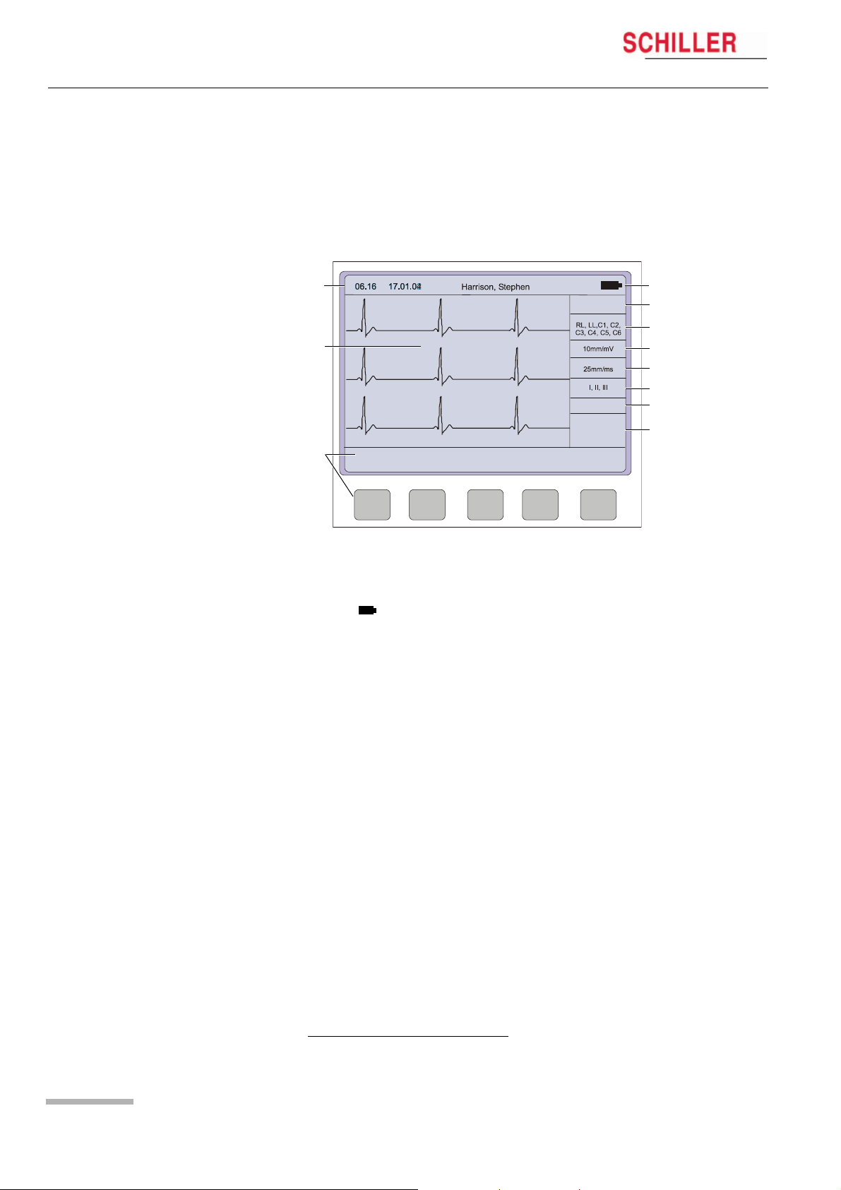
The following is an example of a typical resting ECG screen.
1
HR:
78 / min
~
4
5
2
6
7
8
FILTER OFF
9
10
3
LEAD
TEST
MANUAL
MENU
Items 1, 2 and 3 are in the same position for all screens.
(1) Top line — time, date, patient name, and current power source — mains (~), or bat-
tery ( ). When battery capacity is limited the battery symbol flashes.
(2) Data acquisition area or data entry area.
(3) Softkey designation. Pressing the key below the text carries out the function in-
dicated. The options available will change according to the screen displayed.
Items 4 to 10 are specific for ECG acquisition only:
Page 14
(4) Current Heart Rate (averaged over 4 beats and refreshed every 2 seconds).
The HR is also given on a manual printout. Note that with an auto mode printout
the HR is averaged over the full 10 seconds of the recording.
(5) Electrode connections — when an electrode indication flashes (an audible alarm
is also given), it indicates that the electrode resistance is too high. The electrode(s) must be reapplied.
(6) Sensitivity 5, 10 or 20 mm/mV. Change the sensitivity with the keys 3 (auto), 4,
5 and 6. An ‘A‘ in this box indicates that automatic sensitivity is selected (auto
mode printout only).
(7) Speed 25 or 50 mm/s. Change the speed with the keys 8 and 9.
(8) Lead indication (leads currently displayed on the screen). Change the lead
group with the < and > keys on the keypad.
1
Myogram Filter indication — ‘Filter ON’ or ‘Filter OFF’. The filter is applied with
(9)
the filter key.
(10) Area for system messages or instructions.
1.The frequency of the filter cutoff is defined on page 37 menu Filters.
Art.-no.: 2.510526 Rev.: c
Operation 3
AT-101 User Guide Start-up and Initial Preparation 3.1
3Operation
3.1 Start-up and Initial Preparation
V Danger of electrical shock. Do not operate the unit if the earth connection is su-
spect or if the mains lead is damaged or suspected of being
damaged.
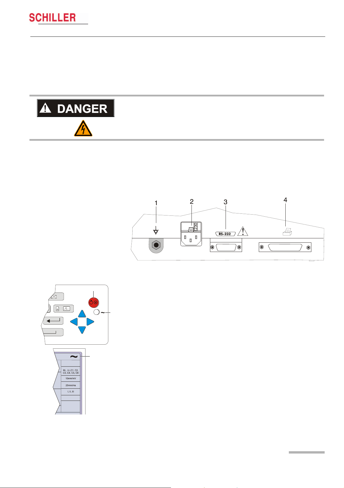
3.1.1 Connecting AT-101
(1) Potential equalisation
(2) Mains connection (100 — 115 or 220 — 240 V)
(3) RS-232 (see safety note paragraph 1.6)
(4) Printer (see safety note paragraph 1.6)
Fig. 3.1 AT-101 back panel
1. Check Voltage setting (2) 115 or 230 V. Refer to chapter 6.4 for the mains voltage.
5
6
7
HR:
78 / min
Art.-no.: 2.510526 Rev.: c
FILTER OFF
2. Connect the power cable at the rear of the unit.
The mains indicator lamp (6) is always lit when the unit is connected to the mains
supply. If the unit is switched on, the relevant symbol is displayed on the LCD (7)
Leave the AT-101 connected to the mains for 7 hours to fully charge the battery.
3. Connect the potential equalisation cable and all other necessary cables at the
rear of the AT-101.
4. Press the on/off button (5). The patient data or the ECG acquisition screen is displayed (see paragraph 5.3.1.)
5. Check the settings according to chapters 5.
6. Connect the patient cable on the right side panel.
Page 15
3Operation
3.1 Start-up and Initial Preparation
3.1.2 Battery Operation
HR:
78 / min
FILTER OFF
1
AT-101
Important
The unit can either be operated from the mains supply or from the built-in rechargeable battery. The power source is indicated on the top line of the LCD. The internal battery provides power for up to 3 hours.
• When the unit is running on battery power a battery symbol (1) is displayed.
• When working from battery power, the unit is automatically switched off after 5 minutes (30 seconds if battery capacity is limited) if no key is pressed.
• for Battery recharging refer to chapter 6.3.
• The unit can remain connected to the mains supply without damage to either the
battery or the unit.
3.1.3 Switching ON and OFF
« The AT-101 is switched ON and OFF with the ON/OFF key.
3.1.4 Isolating the Mains Supply
To isolate the power supply, remove the mains plug from the wall socket.
(see Fig. 3.1)
3.1.5 Potential Equalisation
The potential equalisation stud (see Fig. Fig. 3.1) at the rear of the unit can be used
to equalise the ground potential of the AT-101 to that of all mains powered equipment
in the vicinity. Use the hospital or building common ground
V To prevent the possibility of leakage current when an external printer is connec-
ted, always ensure that the mains lead, or the potential equalisation (next to the
mains connector), is attached to the AT-101
A yellow/green ground cable for connection to the potential equalisation stud is supplied as an option (Article number 2.310005).
Page 16
Art.-no.: 2.510526 Rev.: c
Operation 3
AT-101 User Guide Start-up and Initial Preparation 3.1
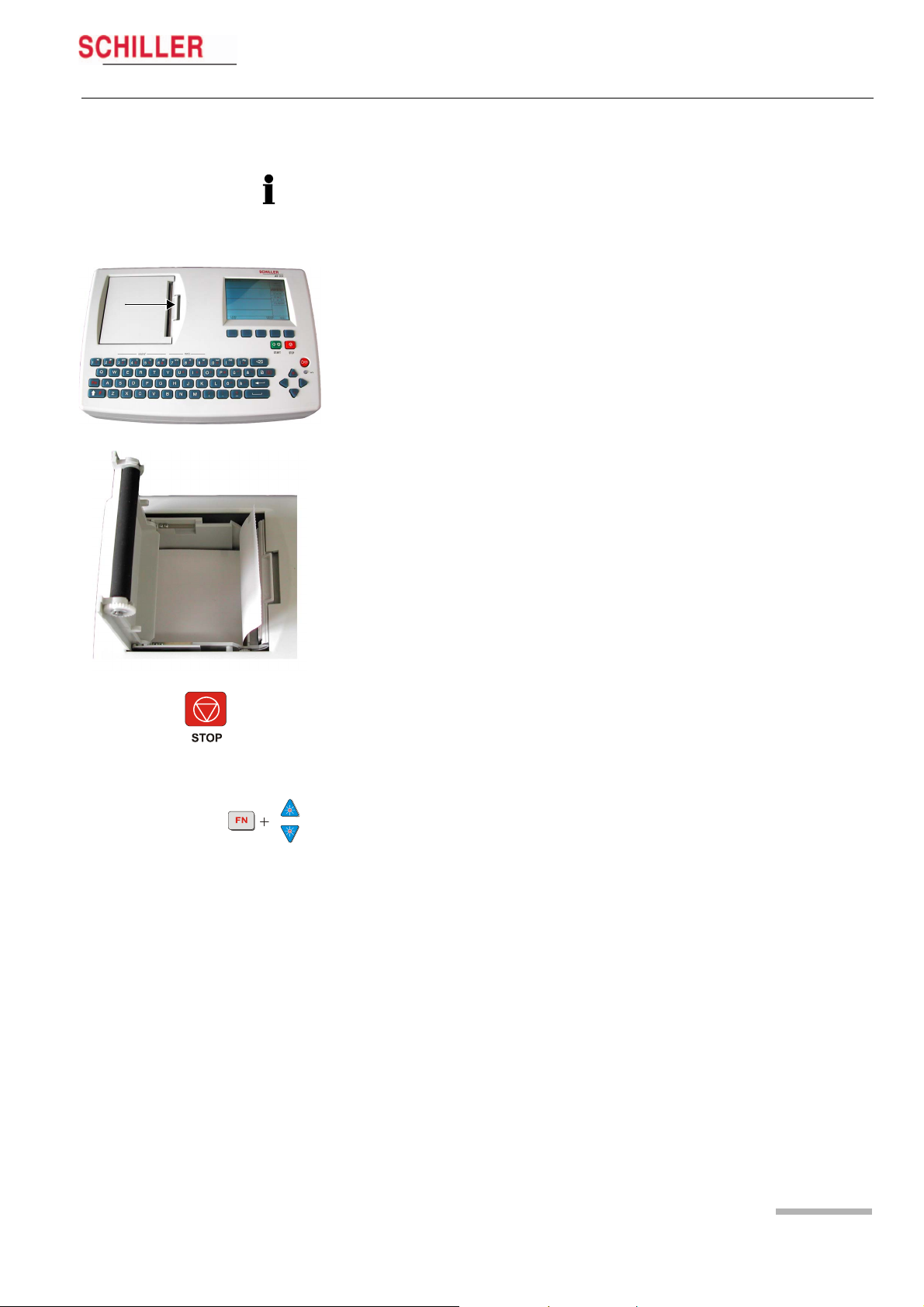
3.1.6 Inserting Printing Paper
Important
The device is delivered without printing paper installed. Only use original SCHILLER
printing paper. The thermo-paper is sensitive to heat, humidity and chemical vapours.
Store the paper in a cool and dry area.
1. Press the locking catch (1) to the right.
1
2. Open the printer door upward.
3. Insert paper and pull it down.
4. Close the cover. Be sure that the paper lies exactly between the rails.
5. Press the STOP key to transport the paper to the start position.
3.1.7 LCD contrast adjustment
« Press the function key FN and the UP/DOWN arrows to adjust screen contrast.
Art.-no.: 2.510526 Rev.: c
Page 17
Loading…
Schiller AT 101 Service manual
- Addeddate
- 2020-05-20 09:06:06
- Classification
- Clinical;Cardiac Equipment;Electrocardiograph (ECG EKG);Welch Allyn Schiller ECG EKG;Schiller AT-101
- Identifier
- manual_Schiller_AT-101_-_Service_manual
- Identifier-ark
- ark:/13960/t8dg5hx17
- Ocr
- ABBYY FineReader 11.0 (Extended OCR)
- Page_number_confidence
- 98.46
- Ppi
- 300
- Scanner
- Internet Archive Python library 1.9.0
comment
Reviews
There are no reviews yet. Be the first one to
write a review.
216
Views
DOWNLOAD OPTIONS
Temporarily Unavailable
DAISY
For users with print-disabilities
Uploaded by
Sketch the Cow
on
-
-
Основные технические характеристики прибора
-
Schiller
AT-101
— 3-канальный
портативный электрокардиограф с
синхронной регистрацией 12 отведений.
Прибор предназначен для эксплуатации
в условиях неотложной помощи,
а также в стационарных условиях
лечебно-профилактических учреждений.
Внешний вид прибора изображен на
рисунке 15.
Рис.
15.
Электрокардиограф
Schiller
AT-101.
Основные
технические характеристики
электрокардиографа Schiller
AT-101
приведены
ниже:
-
Размеры:
290×198×76 мм, масса – 2.6 кг. -
Отведения,
регистрируемые электрокардиографом:
I;
II;
III;
αVR;
αVL;
αVF;
V
и D,
A,
I
по Нэбу. -
Чувствительность
ξ: 5, 10, 20 мм/мВ. -
Скорость
подачи бумаги V: 5, 10, 25 и 50 мм/с.
Стандартные
характеристики:
-
буквенно-цифровая
клавиатура и выделенные функциональные
клавиши для простого удобного управления; -
встроенный
высококачественный термопринтер с
различными опциями формата печати,
определяемые пользователем; -
измерения
и усредненные циклы с возможностью
автоматической и ручной распечатки
регистрации.
Дополнительные
возможности:
-
внешний
принтер; -
интерпретация
ЭКГ; -
память
на 40 регистраций; -
передача
данных в ПК.
Кабель
отведений предназначен для подключения
электродов, наложенных на тело пациента,
к электрокардиографу. Кабель отведений
состоит из десяти проводов, соответствующих
числу электродов и оканчивающихся
штырями. Биоэлектрические
сигналы через кабель отведений подаются
на вход усилительного блока
электрокардиографа.
Все
электродные провода имеют цветокодировку;
нужно следовать руководству для снятия
ЭКГ в тех или иных отведениях, чтобы
соединить каждый провод с соответствующим
электродом.
Электроды,
накладываемые на конечности, представляют
собой клипсы, для монтажа которых не
требуется больших усилий. Грудные
электроды выполнены в грушевидном
исполнении. Всего в комплекте кардиографа
4 электрода на конечности и 6 грудных.
Для
уменьшения сопротивления кожи человека
следует использовать
контактный высокопроводящий гель. Слой
геля наносится на кожу в месте наложения
электрода.
Электрокардиограф
может работать как от сети, так и от
встроенного аккумулятора. Встроенный
аккумулятор гарантирует до 3 часов
работы.
-
Структурная схема и основные элементы
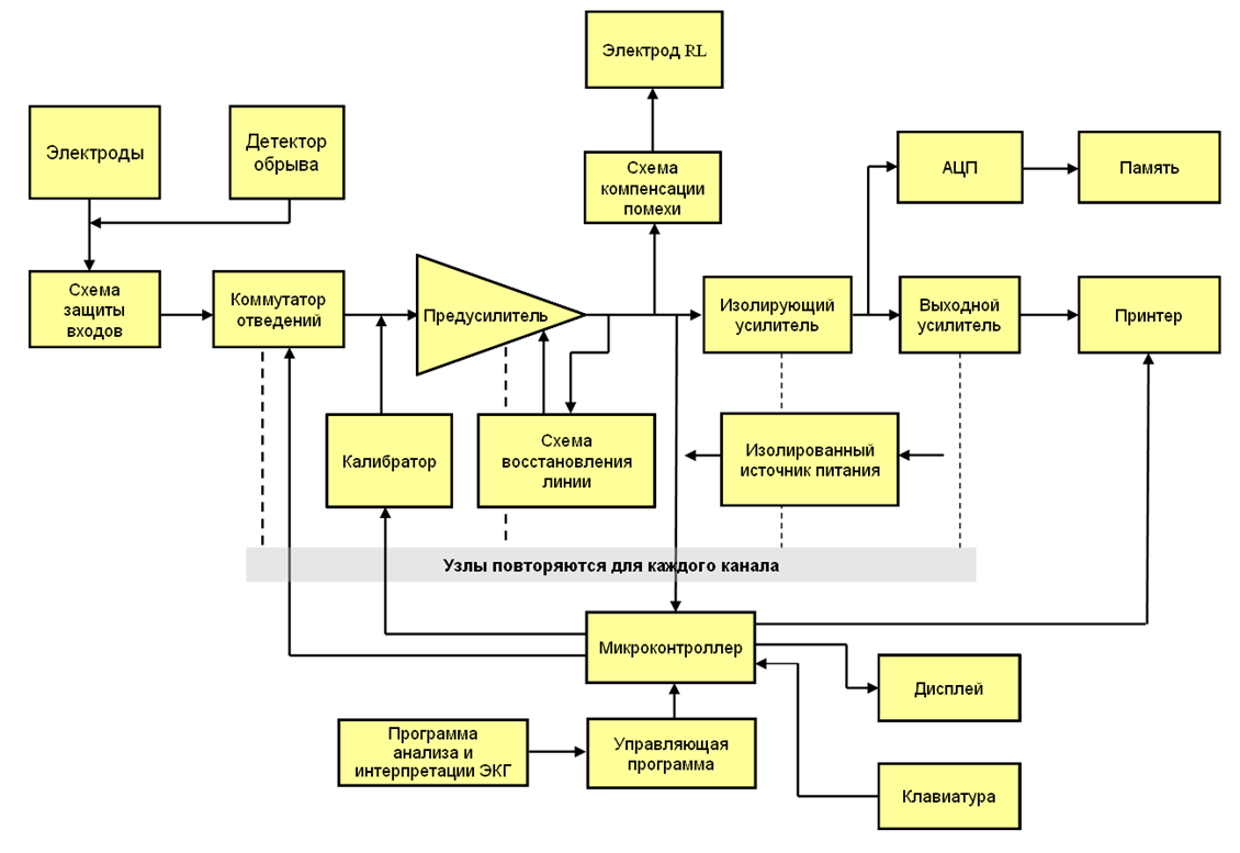
Рис.16.
Блок-схема типичного клинического
электрокардиографа.
Схема
защиты.
Эта схема обеспечивает защиту входных
цепей электрокардиографа от высоких
напряжений.
Коммутатор
отведений.
Все электроды подключаются к усилителю
через коммутатор отведений, который
выбирает два электрода либо электрод
и псевдоэлектрод, подключаемые к входам
каждого канала усиления. Псевдоэлектроды,
такие как объединенный электрод Вильсона,
также формируются в этом блоке.
Коммутатором отведений управляет
оператор либо микроконтроллер. В
автоматическом режиме каждое из 12
отведений записывается в течение
небольшого времени, например 10 секунд.
Калибратор.
Калибровочный сигнал с амплитудой 1
мВ может быть временно
подключен
к входу электрокардиографа
для его проверки.
Предусилитель.
Осуществляет
начальное усиление сигнала ЭКГ.
Должен
иметь очень большое входное сопротивление
и
КОСС. Обычно используется инструментальный
усилитель. Часто имеет переключаемый
коэффициент усиления.
Блок
изоляции.
Формирует
гальванический барьер между цепями,
присоединенными к пациенту, и остальной
частью схемы. Даже если
на пациента случайно будет подано
сетевое напряжение, гальванический
барьер предотвращает протекание опасного
тока на землю самописца или компьютера.
Схема
компенсации синфазной помехи.
Электрод RL
подключается
либо к земле усилителя, либо к схеме
компенсации помехи.
Выходной
усилитель мощности.
Усиливает ЭКГ до входного уровня
самописца. Часто позволяет добавлять
постоянное смещение на выходе, чтобы
управлять положением записи на бумаге.
Блок
памяти.
Многие современные электрокардиографы
не только записывают ЭКГ на бумаге, но
и сохраняют в памяти. Для этого сигнал
подается на аналогово-цифровой
преобразователь (АЦП), и цифровые отсчеты
заносятся в память. Вместе с ними
сохраняется информация о пациенте,
введенная с клавиатуры. Все это происходит
под управлением микроконтроллера.
Микроконтроллер.
Управляет работой электрокардиографа
в целом. Когда оператор выбирает тот
или иной режим работы, вызывается
соответствующая программа. Например,
можно заставить прибор записать три
10-секундных фрагмента шести фронтальных
отведений, а затем три 10-секундных
фрагмента шести грудных отведений. В
некоторых электрокардиографах
микроконтроллер осуществляет также
анализ ЭКГ: определение частоты сердечных
сокращений, распознавание определенных
аритмий, определение электрических
осей зубцов ЭКГ и временных интервалов
между зубцами.
Самописец
или принтер.
Осуществляет запись или распечатку ЭКГ
на бумаге. Также распечатывает имя
пациента, другую
информацию,
введенную оператором, и результаты
автоматического анализа ЭКГ. В прошлом
использовались аналоговые самописцы,
современные приборы используют
термопечать или электростатические
принтеры, в которых единственным
механическим узлом является подача
бумаги, а печатающая головка неподвижна.
Электроды
для снятия биопотенциалов с поверхности
тела представляют собой токопроводящие
(обычно металлические) круглые или
прямоугольные пластинки небольшой
площади. Электроды укрепляются на теле
с помощью клипс или резиновыми присосками.
Для уменьшения сопротивления кожи
человека используют электродный
контактный гель с высокой электропроводностью.
Все
электроды подключаются к усилителю
через коммутатор отведений, который
выбирает два электрода либо электрод
и псевдоэлектрод, подключаемые к входам
каждого канала усиления. Псевдоэлектроды,
такие как объединенный электрод Вильсона,
также формируются в этом блоке.
Система
усиления биопотенциалов (включающая
предусилитель и усилитель мощности)
должна обеспечивать без существенных
искажений усиление снимаемых с электродов
биопотенциалов для их последующей
регистрации.
С
выхода усилителя усиленные биопотенциалы
поступают на регистрирующее устройство.
С помощью регистратора биопотенциалы
представляются в виде записанной тем
или иным образом кривой, которая может
быть подвергнута последующему анализу.
Наибольшее распространение получили
чернильная и тепловая запись.
Для
получения графической зависимости
изменений биопотенциалов во времени
бумажная лента должна протягиваться с
постоянной скоростью. Такое протягивание
обеспечивается лентопротяжным механизмом
с электроприводом. Скорость протягивания
определяется частотным спектром
биопотенциалов и обычно составляет 25
и 50 мм/с.
Все
большее значение сейчас начинают играть
цифровые способы записи информации.
При этом роль регистратора выполняет
электронная память компьютера или
самого электрокардиографа. Для этого
сигнал усилителя преобразуется в
цифровой код. Частота дискретизации
берется такой, чтобы по мгновенным
выборкам напряжения можно было бы
восстановить форму интересующих кривых
изменения потенциала. При таком подходе
к выходу усилителя биопотенциалов
подключается аналого-цифровой
преобразователь. Его сигналы записываются
в память кардиографа и через соответствующий
интерфейс могут быть переданы в память
компьютера. Из нее информация может
быть выведена на экран монитора или
подвергнута соответствующей обработке.
III. Электрокардиограф
Schiller
AT-101. Порядок
выполнения работы
-
Подготовка
электрокардиографа к работе-
Подключить
электрокардиограф к сети питания. -
Наложить
электроды на пациента. -
Включить
электрокардиограф.
-
-
Запись
электрокардиограммы
2.1.
Создать нового пациента, ввести его
данные: ФИО, дату рождения, рост, вес и
т.д.
2.2.
Войти в Экран
получения данных и регистрации ЭКГ
2.3.
Выбрать регистрируемые отведения (I,
II,
III)
2.4.
Включить миографический фильтр.
2.5.
Выставить скорость лентопротяжного
механизма 25 mm/s.
2.6.
Записать ЭКГ.
-
Обработка
записей ЭКГ
3.1.
Для всех трех отведений произвести
измерение высоты h зубцов ЭКГ. По
измеренной высоте h,
при заданной чувствительности вычислить
разность потенциалов:
U=h/S,
мВ, соответствующую каждому зубцу
3.2.
Результаты занести в табл. 2.
Табл.
2. Амплитуда зубцов в отведениях.
|
Зубцы |
I |
II |
III |
Норма, |
||||||
|
h, |
S, |
U, |
h, |
S, |
U, |
h, |
S, |
U, |
||
|
P |
0,05 |
|||||||||
|
Q |
0 |
|||||||||
|
R |
0,6 |
|||||||||
|
S |
0 |
|||||||||
|
T |
0,25 |
Примечание:
коэффициент усиления электрокардиографа
должен быть одинаковым в I и III отведениях.
3.3.
Произвести измерение длительности
временных интервалов ЭКГ для I
отведения. Для этого расстояния между
соответствующими зубцами (рис.1),
измеренные по ЭКГ, разделить на скорость
V
движения ленты (скорость записи).
3.4.
Результаты занести в табл. 2.
Табл.
3. Интервалы времени между зубцами в
отведении.
|
Интервал |
P |
QRS |
Q |
R |
|
V, |
||||
|
l, |
||||
|
t, |
||||
|
Норма, |
0,12 |
0,06 |
0,35 |
0,3 |
3.5.
Определить частоту пульса пациента по
длительности интервала R–R.
Примечание:
ЧСС в норме составляет 60 – 90 уд./мин.
,
где 60 – число секунд в минуте, R-R’ –
длительность интервала, выраженная в
секундах.
3.6.
По данным таблицы 1 вычислить проекции
ИЭВС для некоторого среднего положения
сердца в ходе сокращения. Значения
проекций вычисляются следующим образом:
OX
= R
– (Q+S),
где
Q,
R,
S
– амплитуды зубцов (Q,
S
– положительные величины).
Вычислить
значения проекций ИЭВС для первого и
третьего отведений: OX1
и OX3.
Построение ИЭВС по двум проекциям
ведется не в привычной прямоугольной
(декартовой) системе координат, а в
гексагональной, связанной с треугольником
Эйнтховена. Эта особенность не меняет
сути самих построений. Построения,
которые необходимо выполнить,
иллюстрируются схемой, изображенной
на рис. 17.
ПР
– правая рука
ЛР
– левая рука
ЛН
– левая нога
Рис.
17. Построение ИЭВС.
Направление
построенного ИЭВС в медицинской
литературе часто называют средней
электрической осью сердца. Средняя
электрическая ось близка к анатомической
оси сердца. Считается нормой, когда угол
α наклона этой оси лежит в пределах 30
-690.
3.7.
Определить направление ИЭВС и вычислить
значение угла α, полученного при
построениях, измерить с помощью
транспортира и сравнить с показателем
нормы.
Примечание:
построение средней электрической оси
сердца в треугольнике Эйнтховена следует
выполнить на миллиметровой бумаге.
Соседние файлы в предмете [НЕСОРТИРОВАННОЕ]
- #
- #
- #
- #
- #
- #
- #
- #
- #
- #
- #
Schiller AT-101 Service handbook
- Schiller
- Medical Equipment
- Service handbook for Schiller AT-101
- schiller-at-101-service-handbook-66_manual.pdf
- 66 |
Pages Preview:
Document Transcription:
See Details
Download
Электрокардиограф Schiller CARDIOVIT AT-101 регистрирует ЭКГ по 12 каналам в автоматическом и ручном режимах. Малогабаритный и легкий, данный прибор прост в применении и используется бригадами скорой помощи на выездах благодаря возможности автономной работы от аккумулятора. Также применяется в стационарах и на дому.
Данная модель располагает встроенным термопринтером для быстрой печати измерений и четким ЖК-дисплеем с подсветкой. Печать возможна и с внешнего принтера: CARDIOVIT AT-101 имеет специальные порты и разъемы для подключения к внешним устройствам, в том числе к ПК для передачи данных.
Вводить информацию о пациентах удобно с алфавитно-цифровой клавиатуры, интегрированной в корпус. Имеются и клавиши быстрого доступа к основным функциям устройства.
В электрокардиограф Schiller CARDIOVIT AT-101 предустановлена программа измерения ЭКГ, в том числе таких параметров, как амплитуда, интервалы, электрические оси и др. Опционально устройство оснащается программой анализа ЭКГ для детей и взрослых, памятью на 40 измерений, программой тромболизиса. При желании, в прибор может быть встроено программное обеспечение SEMA для управления данными.
Весит аппарат всего 2,6 кг, в комплект с устройством входит сумка для удобной переноски и хранения.
Основные преимущества:
- Четкий ЖК-дисплей с подсветкой;
- Алфавитно-цифровая клавиатура;
- Регистрация ЭКГ в 12 отведениях;
- Передача данных на ПК;
- Встроенный термопринтер;
- Печать на внешнем принтере в формате А4;
- Память на 40 измерений ЭКГ;
- Работа от аккумулятора до 6 часов;
- Программа измерения «М»;
- Малогабаритный и легкий;
- Широкие опциональные возможности;
- Сумка в комплекте.
Характеристики
|
Количество регистрируемых каналов |
3 |
|
Отведения |
12 |
|
Размеры |
29 х 19,8 х 7,6 см |
|
Вес |
2,6 кг |
|
Дисплей |
ЖК, 320 х 240 пикселей (76 х 57 мм) |
|
Память |
40 ЭКГ (опция) |
|
Автономная работа |
от аккумулятора, до 6 ч в режиме ожидания, 3 ч эксплуатации или 20 регистраций ЭКГ с распечаткой |
|
Электропитание |
220-240 В, 50/60 Гц |
|
Дополнительные функции и характеристики |
Программа измерения ЭКГ — Да, Программа тромболизиса — Опция, Программа интерпретации ЭКГ — Опция, • Программа управления данными SEMA — Опция |
|
Модель |
CARDIOVIT AT-101 |
|
Страна производства |
Швейцария |