
Перейти к контенту
Материнские платы Gigabyte
- Размер инструкции: 16.85 Мб
- Формат файла: pdf
Если вы потеряли инструкцию от материнской платы Gigabyte GA H55 UD3H rev 1 3, можете скачать файл для просмотра на компьютере или печати.
Инструкция для материнской платы Gigabyte GA H55 UD3H rev 1 3 на русском языке. В руководстве описаны возможности и полезные функции, а также правила эксплуатации. Перед использованием внимательно ознакомьтесь с инструкцией.
Чтобы не читать всю инструкцию вы можете выполнить поиск по содержимому внутри инструкции и быстро найти необходимую информацию. Рекомендации по использованию помогут увеличить срок службы материнской платы Gigabyte GA H55 UD3H rev 1 3. Если у вас появилась проблема, то найдите раздел с описанием неисправностей и способами их решения. В нем указаны типичные поломки и способы их решения.
-
Драйверы
15
-
Инструкции по эксплуатации
15
Языки:
Gigabyte GA-H55-UD3H инструкция по эксплуатации
(72 страницы)
- Языки:Венгерский, Греческий, Испанский, Итальянский, Немецкий, Польский, Португальский, Русский, Турецкий, Французский, Чешский
-
Тип:
PDF -
Размер:
18.6 MB -
Описание:
Installation Guidebook
На NoDevice можно скачать инструкцию по эксплуатации для Gigabyte GA-H55-UD3H. Руководство пользователя необходимо для ознакомления с правилами установки и эксплуатации Gigabyte GA-H55-UD3H. Инструкции по использованию помогут правильно настроить Gigabyte GA-H55-UD3H, исправить ошибки и выявить неполадки.
-
Страница 1
GA-H55-UD3H LGA1 156 socket motherboard for Intel ® Core ™ i7 processor family/ Intel ® Core ™ i5 processor family/ Intel ® Core ™ i3 processor family User’s Manual Rev . 1001 12ME-H55UD3H-1001R[…]
-
Страница 2
Motherboard GA-H55-UD3H Dec. 1 1, 2009 Dec. 1 1, 2009 Motherboard GA-H55-UD3H[…]
-
Страница 3
Copyright © 2009 GIGA-BYTE TECHNOLOGY CO., L TD. All rights reserved. The trademarks mentioned in this manual are legally registered to their respective owners. Disclaimer Information in this manual is protected by copyright laws and is the property of GIGABYTE. Changes to the specifications and feature s in this manual may be made by GIGABYTE wit[…]
-
Страница 4
— 4 — T able of Contents Box Contents ……………………………………………………………………………………………………. 6 Optional Items ………………………………………………………………………………………………….. 6 GA-H55-UD3H Motherboard Layout …………………………..[…]
-
Страница 5
— 5 — Chapter 3 Drivers Installation ……………………………………………………………………………. 59 3-1 Installing Chipset Drivers ……………………………………………………………………. 59 3-2 Application Software ……………………………………………………………………….[…]
-
Страница 6
— 6 — Box Contents GA-H55-UD3H motherboard Motherboard driver disk User’s Manual Quick Installation Guide One IDE cable T wo SA T A 3Gb/s cables I/O Shield Optional Items Floppy disk drive cable (Part No. 12CF1-1FD001-7*R) 2-port USB 2.0 bracket (Part No. 12CR1-1UB030-5*R) 2-port SA T A power cable (Part No. 12CF1-2SERPW -0*R) S/PDIF In cable […]
-
Страница 7
— 7 — GA-H55-UD3H Motherboard Layout KB_USB CPU_F AN A TX_12V A TX CD_IN F_AUDIO AUDIO B_BIOS PCIEX4 PCIEX1 IDE SPDIF_I DDR3_1 DDR3_3 DDR3_2 DDR3_4 BA T F_P ANEL F_USB2 COMA IT8720 Intel ® H55 SA T A2_1 SA T A2_3 SA T A2_5 SA T A2_0 SA T A2_2 SA T A2_4 CLR_CMOS CODEC M_BIOS PCI1 PCIEX16 SPDIF_O F_USB1 SYS_F AN1 LGA1 156 GA-H55-UD3H PWR_F AN OPTICA[…]
-
Страница 8
— 8 — Block Diagram (Note) Y ou can use only one of the onboard digital graphics ports (e.g. HDMI and DVI-D) for output when in the BIOS Setup program or when during the POST screens. Center/Subwoofer Speaker Out Line Out MIC Line In S/PDIF In S/PDIF Out Side Speaker Out Surround Speaker Out CODEC PS/2 KB/Mouse LGA1 156 CPU DMI Interface 4 PCI PCI […]
-
Страница 9
— 9 — Hardware Installation 1- 1 Installation Pr ecautions Th e mo the rb oar d co nt ain s nu me rou s de li ca te e lec tr oni c ci rc uit s an d co mp one nt s wh ic h ca n become damaged as a result of electrostatic discharge (ESD). Prior to installation, carefully read the user’s manual and follow these procedures: • Prio r to instal[…]
-
Страница 10
Hardware Installation — 10 — 1- 2 Product Specications CPU Support for an Intel ® Core ™ i7 series processor/Intel ® Core ™ i5 series processor/ Intel ® Core ™ i3 series processor in the LGA1 156 package (Go to GIGABYTE’s website for the latest CPU support list.) L3 cache varies with CPU Chipset Intel ® H55 Express Chi[…]
-
Страница 11
— 1 1 — Hardware Installation USB Chipset: — Up to 12 USB 2.0/1.1 ports (8 on the back panel, 4 via the USB brackets connected to the internal USB headers) Internal 1 x 24-pin A TX main power connector Connectors 1 x 4-pin A TX 12V power connector 1xoppydiskdriveconnector 1 x IDE connector 6 x SA TA 3Gb[…]
-
Страница 12
Hardware Installation — 12 — BIOS 2x64Mbitash Use of licensed A WARD BIOS Support for DualBIOS ™ PnP 1.0a, DMI 2.0, SM BIOS 2.4, ACPI 1.0b Unique Features Support for @BIOS Support for Q-Flash Support for Xpress BIOS Rescue Support for Download Center Support for Xpress Install Support fo[…]
-
Страница 13
— 13 — Hardware Installation 1-3 Installing the CPU and C PU Cooler 1-3 -1 I nsta lling t he CPU A. Locate the alignment keys on the motherboard CPU socket and the notches on the CPU. Read the following guidelines before you begin to install the CPU: • Make sure that the motherboard supports the CPU. (Go to GIGABYTE’s website for the late[…]
-
Страница 14
Hardware Installation — 14 — Step 1: Gently press the CPU socket lever handle down and away from the socket with your nger . Then completely lift the CPU socket lever and the metal load plate will be lifted as well. Step 3: HoldtheCPUwithyourthumbandindexngers. Align the CPU pin one markin[…]
-
Страница 15
— 15 — Hardware Installation 1-3 -2 I nsta lling t he CPU Coo ler Follow the steps below to correctly install the CPU cooler on the motherboard. (The following procedure uses Intel ® boxed cooler as the example cooler .) Step 1: Apply an even and thin layer of thermal grease on the surface of the installed CPU. Male Push Pin Female Push Pin The T […]
-
Страница 16
Hardware Installation — 16 — 1- 4 -1 Du al Chann el Me mor y Cong urat ion This motherboard provides four DDR3 memory socket s and support s Dual Chann el T echnology. After the memory is installed, the BIOS will automatically detect the specications and capacity of the memory . En — abling Dual Ch[…]
-
Страница 17
— 17 — Hardware Installation 1- 4 -2 In sta lling a M emo r y Notch DDR3 DIMM Before installing a memory module, make sure to turn off the computer and unplug the power cord from the power outlet to prevent damage to the memory module. DDR3 and DDR2 DIMMs are not compatible to each other or DDR DIMMs. Be sure to install DDR3 DIMMs on this motherboa[…]
-
Страница 18
Hardware Installation — 18 — 1-5 Installing an Expansion Card Follow the steps below to correctly install your expansion card in the expansion slot. 1. Locate an expansion slot that supports your card. Remove the metal slot cover from the chassis back panel. 2. Align the card with the slot, and press down on the card until it is fully seated in the[…]
-
Страница 19
— 19 — Hardware Installation 1-6 Back Panel Connectors USB 2.0/1.1 Port TheUSBport supportstheUSB 2.0/1.1specication.Use thisportfor USBdevicessuchas aUSBkey — board/mouse,USBprinter ,USBashdriveandetc. PS/2 Keyboard and PS/2 Mouse Port Use this port to connect a P[…]
-
Страница 20
Hardware Installation — 20 — Center/Subwoofer Speaker Out Jack (Orange) Usethisaudiojacktoconnectcenter/subwooferspeakersina5.1/7.1-channelaudioconguration. Rear Speaker Out Jack (Black) Usethisaudiojacktoconnectrearspeakersina7.1-channelaudioconguration. Side […]
-
Страница 21
— 21 — Hardware Installation 1- 7 Inter nal Connectors Read the following guidelines before connecting external devices: • First make sure your devices are compliant with the connectors you wish to connect. • Befor e i nstal ling th e de vice s, b e s ure to tur n off th e de vices a nd y our com puter. Un plug the power cord from the pow[…]
-
Страница 22
Hardware Installation — 22 — G.QBOFM 13 1 24 12 A TX A TX: PinNo. Denition 13 3.3V 14 -12V 15 GND 16 PS_ON (soft On/Off) 17 GND 18 GND 19 GND 20 -5V 21 +5V 22 +5V 23 +5V (Only for 2×12-pi n A TX) 24 GND ( On ly for 2x 12- pi n A TX) PinNo. Denition 1 3.3V 2 3.3V 3 GND 4 +5V 5 GND 6 +5V 7 GND 8 Power Good 9 5VSB (stand by +5V) 10 +[…]
-
Страница 23
— 23 — Hardware Installation 3/4/5) CPU_F AN/SYS_F AN1/SYS_FAN2/PWR_F AN (Fan Headers) The motherboard has a 4-pin CPU fan header (CPU_FAN), a 4-pin (SYS_FAN2) and two 3-pin (SYS_ F AN1) system fan headers, and a 3-pin power fan header (PWR_FAN). Most fan headers possess a foolproof insertion design. When connecting a fan cable, be sure to connect […]
-
Страница 24
Hardware Installation — 24 — 7) IDE (IDE Connector) The IDE connector supports up to two IDE devices such as hard drives and optical drives. Before attach- ing the IDE cable, locate the foolproof groove on the connector. If you wish to connect two IDE devices, remember to set the j umpers and th e cabli ng acco rding t o the role of the IDE devices[…]
-
Страница 25
— 25 — Hardware Installation 9) F_P ANEL (Front Panel Header) Conne ct the power sw itch, res et switc h, s peake r , ch assis in trusio n s witch/ senso r an d s ystem sta tus indicator on the chassis to this header according to the pin assignments below. Note the positive and negative pins before connecting the cables. • PW (Power Switch, Red):[…]
-
Страница 26
Hardware Installation — 26 — 10) F_AUDIO (Front Panel Audio Header) ThefrontpanelaudioheadersupportsIn telHighDenitionaudio(HD)andAC’97audio. Y oumayconnect your chassis front panel audio module to this header. Make sure the wire assignments of the module con — nector match the pin assi[…]
-
Страница 27
— 27 — Hardware Installation 12) SPDIF_I (S/PDIF In Header) This header supports digital S/PDIF In and can connect to an audio device that supports digital audio out via an optional S/PDIF In cable. For purchasing the optional S/PDIF In cable, please contact the local dealer . PinNo. Denition 1 Power 2 SPDIFI 3 GND PinNo. Denition[…]
-
Страница 28
Hardware Installation — 28 — 14) F_USB1/F_USB2 (USB Headers) Theheaders conform to USB2.0/1.1 specication. Each USBheader can providetwo USB ports viaan optional USB bracket. For purchasing the optional USB bracket, please contact the local dealer . G.QBOFM 10 9 2 1 PinNo. Denition […]
-
Страница 29
— 29 — Hardware Installation 16) BA T (BA TTER Y) Thebatteryprovidespowertokeepthevalues(suchasBIOScongurations,date,and timeinformation) in the CMOS when the computer is turned off. Replace the battery when the battery voltage drops to a low level, or the CMOS values may not be accurate or may[…]
-
Страница 30
Hardware Installation — 30 — 18) PHASE LED The nu mber of li ght ed LEDs in dica tes th e CP U l oad ing. The hi gher th e C PU loa ding , t he more th e numberoflightedLEDs.T oenable thePhaseLEDdisplay function,pleaserst enableDynamicEnergy Saver ™ 2. Refer to Chapter 4, «Dynamic Energy […]
-
Страница 31
— 31 — BIOS Setup BIOS (Basic In put and Output Sys tem) records ha rdware param eters of the syste m in the CMO S on th e motherboard. Its major functions include conducting the Power-On Self-T est (POST) during system startup, saving syste m par ameters and loadin g ope rating system , etc . BIO S in cludes a BIOS Setup program tha t allows th[…]
-
Страница 32
BIOS Setup — 32 — 2-1 Startup Screen The following screens may appear when the computer boots. A. The LOGO Screen (Default) B. The POST Screen Function Keys: <T AB>: POST SCREEN Press the <T ab> key to show the BIOS POST screen. T o show the BIOS POST screen at system start- up, refer to the instructions on the Full Screen LOGO Show ite[…]
-
Страница 33
— 33 — BIOS Setup 2-2 The Main Menu Once you enter the BIOS Setup program, the Main Menu (as shown below) appears on the screen. Use ar- row keys to move among the items and press <Enter> to accept or enter a sub-menu. (Sample BIOS V ersion: E7) Main Menu Help The on-screen description of a highlighted setup option is displayed on the bottom […]
-
Страница 34
BIOS Setup — 34 — The Functions of the <F1 1> and <F12> keys (For the Main Menu Only) F1 1: Save CMOS to BIOS This function allows you to save the current BIOS settings to a prole. Y ou can create up to 8 proles (Prole 1-8) and name each p[…]
-
Страница 35
— 35 — BIOS Setup 2-3 MB Intelligent T weaker(M.I.T .) Whether the system will work stably with the overclock/overvoltage settings you made is dependent on your overall system congurations. Incorrectly doing overclock/overvoltage may result in dam — age to CPU, chipset, or memory and reduce the useful life of the[…]
-
Страница 36
BIOS Setup — 36 — CPU Clock Ratio Allows you to alter the clock ratio for the installed CPU. The adjustable range is dependent on the CPU being installed. CPU Frequency Displays the current operating CPU frequency . (Note) This item is present only if you install a CPU that supports this feature. For more information about Intel CPUs’ unique f[…]
-
Страница 37
— 37 — BIOS Setup (Note) This item is present only if you install a CPU that supports this feature. For more information about Intel CPUs’ unique features, please visit Intel’s website. C3/C6/C7 State Support (Note) Allows you to determine whether to let the CPU enter C3/C6/C7 mode in system halt state. When en- abled, the CPU core freque[…]
-
Страница 38
BIOS Setup — 38 — (Note) This item appears only if you install a memory module that supports this feature. Extreme Memory Prole (X.M.P .) (Note) Allows the BIOS to read the SPD data on XMP memory module(s) to enhance memory performance when enabled. Disabled Disables this function. (Default) Prole1 UsesProle1settings. Pro?[…]
-
Страница 39
— 39 — BIOS Setup CMOS Setup Utility-Copyright (C) 1984-2009 A ward Software Advanced Memory Settings higf : Move Enter: Select +/-/PU/PD: V alue F10: Save ESC: Exit F1: General Help F5: Previous V alues F6: Fail-Safe Defaults F7: Optimized Defaults Item Help Menu Level ExtremeMemoryProle(X.M.P .) (Note) [Disabled] System […]
-
Страница 40
BIOS Setup — 40 — CMOS Setup Utility-Copyright (C) 1984-2009 A ward Software Channel A T iming Settings higf : Move Enter: Select +/-/PU/PD: V alue F10: Save ESC: Exit F1: General Help F5: Previous V alues F6: Fail-Safe Defaults F7: Optimized Defaults Item Help Menu Level >>>>> Channel A Standard T iming Control x CAS La[…]
-
Страница 41
— 41 — BIOS Setup t FAW Options are: Auto (default), 1~63. Command Rate(CMD) Options are: Auto (default), 1~3. >>>>> Channel A/B Misc T iming Control Static tRD Options are: Auto (default), 1~31. Advanced V oltage Settings >>> CPU Load-Line Calibration Ena bl es or di sa ble s Loa d- Lin e C al ibr at ion . Ena bl ing th[…]
-
Страница 42
BIOS Setup — 42 — >>> DRAM DRAM V oltage The default is Auto . DRAM T ermination The default is Auto . Ch-A Data VRef. The default is Auto . Ch-B Data VRef. The default is Auto . Ch-A Address VRef. The default is Auto . Ch-B Address VRef. The default is Auto . Miscellaneous Settings CMOS Setup Utility-Copyright (C) 1984-2009 A ward Sof[…]
-
Страница 43
— 43 — BIOS Setup This section provides information on the BIOS version, CPU base clock, CPU frequency , memory frequency , total memory size , CPU temperature, Chipset temperature, Vcore, and memory voltage. CMOS Setup Utility-Copyright (C) 1984-2009 A ward Software MB Intelligent T weaker(M.I.T .) higf : Move Enter: Select +/-/PU/PD: V alue F10: […]
-
Страница 44
BIOS Setup — 44 — Date (mm:dd:yy) Setsthesystemdate.Thedateformatisweek(re ad-only),month,dateandyear .Selectthedesiredeld and use the up arrow or down arrow key to set the date. Time (hh:mm:ss) Sets the system time. For example, 1 p.m. is 13:0:0. Select?[…]
-
Страница 45
— 45 — BIOS Setup The following elds display your harddrive specications. If you wish to enter the parameters manually , refer to the information on the hard drive. Capacity Approximate capacity of the currently installed hard drive. Cylinder Number of cylinders. Head Number of heads. Precom[…]
-
Страница 46
BIOS Setup — 46 — (Note) This item is present only if you install a CPU that supports this feature. For more information about Intel CPUs’ unique features, please visit Intel’s website. 2-5 Advanced BIOS Features Hard Disk Boot Priority Species the sequence of loading the operating system from the inst[…]
-
Страница 47
— 47 — BIOS Setup HDD S.M.A.R.T . Capability Enables or disables the S.M.A.R.T . (Self Monitoring and Reporting T echnology) capability of your hard drive. This feature allows your system to report read/write errors of the hard drive and to issue warnings when a third party hardware monitor utility is installed. (Default: Disabled) Limit CPUID Max.[…]
-
Страница 48
BIOS Setup — 48 — 2-6 Integrated Peripherals SA T A AHCI Mode (Intel H55 Chipset) AllowsyoutodecidewhethertoconguretheSA T AcontrollerintegratedintheIntelH55Chipsetto AHCI mode. IDE CongurestheSA T A controllertoIDEmode.(Default) AHCI Congures[…]
-
Страница 49
— 49 — BIOS Setup Onboard H/W LAN Enables or disables the onboard LAN function. (Default: Enabled) If you wish to install a 3rd party add-in network card instead of using the onboard LAN, set this item to Disabled . Green LAN When the onboard LAN function and Green LAN are enabled, the system will dynamically detect if a LAN cable is connected or n[…]
-
Страница 50
BIOS Setup — 50 — Onboard LAN Boot ROM Allows you to decide whether to activate the boot ROM integrated with the onboard LAN chip. (Default: Disabled) Onboard IDE Controller (iTE IT8213 Chip) Enables or disables the IDE controller integrated in the iTE IT8213 chip. (Default: Enabled) Onboard Serial Port 1 Enables or disables the […]
-
Страница 51
— 51 — BIOS Setup ACPI Suspend T ype Speciesthe ACPIsleepstatewhenthesystementerssuspend. S1(POS) Enables the system to enter the ACPI S1 (Power on Suspend) sleep state. In S1 sleep state, the system appears suspended and stays in a low power mode. The system can be resumed at any time. S3(STR) Enables the syste[…]
-
Страница 52
BIOS Setup — 52 — (Note) Supported on Windows 7/Vista operating system only . Date (of Month)Alarm: T urn on the system at a specic time on each day or on a specic day in a month. Time (hh: mm: ss) Alarm: Set the time at which the system will be powered on automatica lly . Note[…]
-
Страница 53
— 53 — BIOS Setup Reset Case Open Status Keeps or clears the record of previous chassis intrusion status. Enabled clears the record of previous chassis intrusion status and the Case Opened eldwillshow»No»atnextboot.(Default:Disabled) Case Opened Displays the detection status of the chassis intrusion detection[…]
-
Страница 54
BIOS Setup — 54 — CPU Smart F AN Mode Specieshowtocontrol CPUfanspeed.Thisitemiscongurable onlyif CPU Smart F AN Control is set to Enabled . Auto Lets the BIOS automatically detect the type of CPU fan installed and sets the optimal CPU fan control mode. (Default) Voltage Sets Voltage mode for a 3-pin[…]
-
Страница 55
— 55 — BIOS Setup Press <Enter> on this item and then press the <Y> key to load the safest BIOS default settings. In case system instability occurs, you may try to load Fail-Safe defaults, which are the safest and most stable BIOS settings for the motherboard. 2-9 Load Fail-Safe Defaults Press <Enter> on this item and then press t[…]
-
Страница 56
BIOS Setup — 56 — Press <Enter> on this item and type the password with up to 8 characters and then press <Enter>. Y ou will berequestedtoconrmthepassword.T ypethepasswordagainandpress<Enter>. The BIOS Setup program allows you to specify two separate passwords: Supervisor Password When a s[…]
-
Страница 57
— 57 — BIOS Setup Press <Enter> on this item and press the <Y> key . This saves the changes to the CMOS and exits the BIOS Setup program. Press <N> or <Esc> to return to the BIOS Setup Main Menu. 2-12 Save & Exit Setup Press <Enter> on this item and press the <Y> key . This exits the BIOS Setup without saving[…]
-
Страница 58
BIOS Setup — 58 -[…]
-
Страница 59
— 59 — Drivers Installation 3-1 Installing Chipset Drivers Chapter 3 Drivers Installation • Beforeinstallingthedrivers,rstinstalltheoperatingsystem. • After installing the operating system, insert the motherboard driver disk into your optical drive. The driver Autorun screen is automatically displayed which look[…]
-
Страница 60
Drivers Installation — 60 — 3-2 Application Software This page displays all the utilities and applications that GIGABYTE develops and some free software. Y ou can click the Install button on the right of an item to install it. 3-3 T echnical Manuals This page provides GIGABYTE’s application guides, content descriptions for this driver disk, an[…]
-
Страница 61
— 61 — Drivers Installation 3-4 Contact For the detailedcontact information of the GIGABYTE T aiwan headquarter or worldwidebranch ofces, click the URL on this page to link to the GIGABYTE website. 3-5 System This page provides the basic system information.[…]
-
Страница 62
Drivers Installation — 62 — 3-6 Download Center T o upd ate the BIOS, drivers, or applications, click the Download Center button to link to the GIGABYTE website. The latest version of the BIOS, drivers, or applications will be displayed. 3-7 New Utilities This page provides a quick link to GIGABYTE’s lately developed utilities for users to ins[…]
-
Страница 63
— 63 — Unique Features 4-1 Xpress Recovery2 Chapter 4 Unique Features Xp re s s R e co ve r y2 i s a u ti l it y th at a ll o ws y ou t o q u ic kl y co m pr es s an d back up your system data and perform restoration of it. Supporting NTFS, F A T32, and F A T16 le systems, Xpress Recovery2 can back up data on […]
-
Страница 64
Unique Features — 64 — Step 3: Wh en p ar t it io ni n g y ou r ha r d d ri v e, ma k e s u re to leave unallocated space (10 GB or more is recom- mended; actual size requirements vary , depending on the amount of data) and begin the installation of the operating system. Step 1: Select BACKUP to start backing up your hard drive data. Step 4: Aft er[…]
-
Страница 65
— 65 — Unique Features D. Using the Restore Function in Xpress Recovery2 E. Removing the Backup F . Exiting Xpress Recovery2 Sel ec t RESTORE t o res to re th e b ack up to y our h ard d riv e i n case the system breaks down. The RESTORE option will not be present if no backup is created before. Select REBOOT to exit Xpress Recovery2. Step 2: After[…]
-
Страница 66
Unique Features — 66 — 4-2 BIOS Update Utilities GI GA BY T E m ot he r bo ar ds p ro vi de t wo u ni qu e BI OS u pd at e to ol s, Q -F la sh ™ a n d @ BI OS ™ . G I GA BY TE Q-Flash and @BIOS are easy-to-use and allow you to update the BIOS without the need to enter MS-DOS mod e. Addi tion all y , th is mot herb oar d f eatu res th e D ual BI[…]
-
Страница 67
— 67 — Unique Features B. Updating the BIOS When updating the BIOS, choose the locati on whe re the BIOS le is saved . The following proce dure as — sumesthatyousavetheBIOSletoaoppydisk. Step 1: 1. InserttheoppydiskcontainingtheBIOS?[…]
-
Страница 68
Unique Features — 68 — Step 4: Press <Esc> and then <Enter> to exit Q-Flash and reboot the system. As the system boots, you should see the new BIOS version is present on the POST screen. Step 5: During the POST , press <Delete> to enter BIOS Setup. Select Load Optimized Defaults and press <Enter> to load BIOS defaults. Syste[…]
-
Страница 69
— 69 — Unique Features 4-2-2 Updating the BIOS with the @BIOS Utility A. Before Y ou Begin 1. In Windows, close all applications and TSR (T erminate and Stay Resident) programs. This helps prevent unexpected failures when performing a BIOS update. 2. Du ring the BIOS updat e p rocess, ensu re t he I nternet con nection is stab le and do N OT int er[…]
-
Страница 70
Unique Features — 70 — 4-3 EasyT une 6 GIGABYTE’s EasyTune 6 is a simple and easy-to-use interface that allows users to ne-tune their system settings or do overclock/overvoltage in Windows environment. The user-friendly EasyTune 6 interface also includes tabbed pages for CPU and memory informa[…]
-
Страница 71
— 71 — Unique Features 4-4 Dynamic Energy Saver ™ 2 GIGABYTE Dynamic Energy Saver ™ 2 (Note 1) is a revolutionary technology that delivers unparalleled power savings with a click of the button. Featuring an advanced proprietary hardware and software design, GIGA- BYTE Dynamic Energy Saver ™ 2isabletoprovideexceptionalpower?[…]
-
Страница 72
Unique Features — 72 — B. T otal Mode In T otal Mode, users are able to see how much total power savings they have accumulated in a set period of time since activating Dynamic Energy Saver ™ 2 for th ersttime (Note 3) . (Note 1) Before using the Dynamic Energy Saver ™ 2 function, make sure the CPU Enhanced Halt (C1E) and CPU EIST Funct[…]
-
Страница 73
— 73 — Unique Features 4-5 Q-Share Q-Share is an easy and convenient data sharing too l. After conguring your LAN connection settings and Q-Share, you are able to share your data with computers on the same network, making full use of Internet resources. Directions for using Q-Share After installing Q-Share from the mother[…]
-
Страница 74
Unique Features — 74 — 4-6 Smart 6 ™ GIGABYTE Smart 6 ™ (Note 1) is designed with user-friendliness i n mind, and offers a comb ination of 6 innovative software utilities that provide easier and smarter PC system management. Smart 6 ™ allows you to speed up systemperformance,reduceboot-up time,manageasecureplatform […]
-
Страница 75
— 75 — Unique Features SMART Recovery With SMART Recovery, users can quickly create backups of changed data les (Note 2) or copy les from a specic backup on P A T A and SA T Ahard drives (partitioned on NTFS le system) in Windows Vista. SMART DualBIOS S[…]
-
Страница 76
Unique Features — 76 — (Note 1) When launching Smart 6 ™ forthersttime,thesystemwillrequestyoutosetupapassword.Thispasswordisrequiredwhen you activate SMART DualBIOS or when you want to make changes to the SMAR T Recorder or SMART TimeLock settings. (Note2) Thechangeddata?[…]
-
Страница 77
— 77 — Unique Features 4-7 Auto Green Auto Green is an easy-to-use tool that provides users with simple options to enable system power savings via a Bluetooth cell phone. When the phone is out of the range of the computer’s Bluetooth receiver , the sys- temwillenterthespeciedpowersavingmode. Sele cti ng a sys tem ene[…]
-
Страница 78
Unique Features — 78 -[…]
-
Страница 79
— 79 — Appendix 5-1-1 Conguring 2/4/5.1/7.1-Channel Audio The motherboard provides six audio jacks on the back pan el wh ich s upp ort 2 /4/ 5.1 /7. 1- cha nne l (Note) a ud io. The picture to the right shows the default audio jack assignments. The integrated HD (High Definition) audio provides jack retasking capability that allows the user to c[…]
-
Страница 80
Appendix — 80 — Step 2: Connect an audio device to an audio jack. The The cur- rent connected device is dialog box appears. Select the device according to the type of device you connect. Then click OK . Step 3: On the Speakers s creen, cli ck the Speak er C ongur a — tion tab. In the Speaker Conguration list, select Stereo , Quadraphonic , 5.[…]
-
Страница 81
— 81 — Appendix 5-1-2 Conguring S/PDIF In/Out A. S/PDIF In The S/PDIF In cable (optional) allows you to input digital audio signals to the computer for audio processing. 1. Installing the S/PDIF In Cable: 2. Conguring S/PDIF In: On the Digital Input screen, click the Default Format tab to select the default format. Click OK to complete. (Note[…]
-
Страница 82
Appendix — 82 — B. S/PDIF Out The S/PDIF Out jack can transmit audio signals to an external decoder for decoding to get the best audio quality . 1. Connecting a S/PDIF Out Cable: 2. Conguring S/PDIF Out: On the Digital Output screen, click the Default Format tab and then select the sample rate and bit depth. Click OK to complete. Connect a S/PDI[…]
-
Страница 83
— 83 — Appendix 5-1-3 Conguring Microphone Recording Step 1: After installing the audio driver , the HD Audio Manager icon willappearinthe noticationarea.Double-click the icon to access the HD Audio Manager . Step 2: Connect your mi crophone to the Mic in jack (pink) on th e b ac k pa ne l o r th e M ic i n ja ck (p in[…]
-
Страница 84
Appendix — 84 — Step 5: After comp leting the sett ings above, cli ck Start , point to All Programs , point to Accessories , and then click Sound Recorder to begin the sound recording. Step 1: Locate the V olume icon in the notication area and right-click on this icon. Select Recording Devices . Step 2: On the Recording tab, r[…]
-
Страница 85
— 85 — Appendix Step 3: When the Stereo Mix item appears, right-click on this item and select Enable . Then set it as the default de- vice. Step 4: Now you can access the HD Audio Manager tocong — ure Stereo Mix and use Sound Recorder to record the sound. 5-1-4 Using the Sound Recorder A. Recording Sound 1. Make sure you have connected th[…]
-
Страница 86
Appendix — 86 — 5-2 T roubleshooting 5-2-1 Frequently Asked Questions T o read more F AQs for your motherboard, please go to the Support&DownloadsMotherboardFAQ page on GIGABYTE’s website. Q: In the BIOS Setup program, why are some BIOS options missing? A: Some advanced options are hidden in the BIOS Setup program. Press <Delete> t[…]
-
Страница 87
— 87 — Appendix 5-2-2 T roubleshooting Procedure If you encounter any troubles during system startup, follow the troubleshooting procedure below to solve the problem. ST ART A Turn off the power . Remove all peripherals, connecting cables, and power cord etc. Isolate the short circuit. Secure the CPU cooler on the CPU. Connect the CPU cooler power […]
-
Страница 88
Appendix — 88 — If the pro cedur e a bove is una ble to solv e y our prob lem, co ntact th e p lace of pur chase or lo cal dealer for help. Or go to the Support&DownloadsT echnical Service Zone page to submit your question. Our customer service staff will reply you as soon as possible. The power supply , CPU or CPU socket might fail. The keybo[…]
-
Страница 89
— 89 — Appendix 5-3 Regulatory Statements Regulatory Notices This document m ust not be copied without our written permission, and the cont ents there of must not be imparted to a third party nor be used for any unauthorized purpose. Contravention will be prosecuted. We believe that the information contained herein was accurate in all respects at t[…]
-
Страница 90
Appendix — 90 — Finally , we suggest that you practice other environmentally friendly actions by understanding and using the energy-saving features of this product (where applicable), recycling the inner and outer packaging (including shipping containers) this product was delive red in, and by disposing of or recycling used batteries properly . Wit[…]
-
Страница 91
— 91 — Appendix[…]
-
Страница 92
Appendix — 92 -[…]
-
Страница 93
— 93 — Appendix[…]
-
Страница 94
Appendix — 94 -[…]
-
Страница 95
— 95 — Appendix Contact Us • GIGA-BYTE TECHNOLOGY CO., L TD. Address: No.6, Bau Chiang Road, Hsin-Tien, T aipei 231, T aiwan TEL: +886-2-8912-4000 F AX: +886-2-8912-4003 T ech. and Non-T ech. Support (Sales/Marketing) : http://ggts.gigabyte.com.tw WEB address (English): http://www .gigabyte.com.tw WEB address (Chinese): http://www .gigabyte.tw ?[…]
-
Страница 96
Appendix — 96 — • G.B.T . TECHNOLOGY TRADING GMBH — Germany WEB address : http://www .gigabyte.de • G.B.T . TECH. CO., L TD. — U.K. WEB address : http://www .giga-byte.co.uk • Giga-Byte T echnology B.V . — The Netherlands WEB address : http://www .giga-byte.nl • GIGABYTE TECHNOLOGY FRANCE — France WEB address : http://www .gigabyte.fr • S[…]
28-02-2010
Выпустив новые процессоры Core i5/Core i3 со встроенным графическим ядром, компания Intel выпустила и новые наборы системной логики Intel H57, H55 и Q57 Express для работы с ними. Отличительные особенности этих чипсетов мы рассматривали в обзоре материнской платы Intel DH55TC. Другие компании-производители материнских плат сразу же взяли на вооружение эти наборы системной логики и представили свои решения на их основе. Компания GIGABYTE выпустила целых четыре платы – на любой вкус, цвет и кошелек. Один из этих четырех продуктов от GIGABYTE мы рассмотрели в обзоре платы GIGABYTE GA-H55-UD2H, а сегодня проведем более детальное ее сравнение с героиней нашего обзора – материнской платой GIGABYTE GA-H55-UD3H.
Спецификация материнской платы GIGABYTE GA-H55-UD3H:
|
Производитель |
GIGABYTE |
|
Модель |
GA-H55-UD3H |
|
Чипсет |
Intel H55 Express |
|
Процессорный разъем |
Socket LGA1156 |
|
Поддерживаемые процессоры |
Intel Core i7/Intel Core i5/Intel Core i3 процессоры под сокет LGA1156 |
|
Используемая память |
DDR3 2200+/1800/1600/1333/1066/800 MГц |
|
Слоты расширения |
1 x PCI Express x1 |
|
MultiGPU |
ATI CrossFireX technology |
|
Дисковая подсистема |
6 x SATA 3.0 Гб/с |
|
LAN |
Гигабитный сетевой LAN контроллер Realtek 8111D |
|
Звуковая подсистема |
8-канальный High-Definition Audio кодек Realtek ALC889 |
|
Питание |
24-контактный разъем питания ATX |
|
Охлаждение |
Пассивная система охлаждения, состоящая из алюминиевых радиаторов и тепловой трубки |
|
Разъемы для вентиляторов |
1 x CPU |
|
Внешние порты I/O |
1 x PS/2 Клавиатура или мышь |
|
Внутренние порты I/O |
1 x CD in |
|
BIOS |
2 x 16 Мбит ПЗУ |
|
Фирменные технологии |
— @BIOS |
|
Форм-фактор Размеры, мм |
ATX |
|
Сайт производителя |
http://gigabyte.com/ Новый BIOS можно скачать со страницы поддержки. |
Все цены на GIGABYTE GA-H55-UD3H
Данный продукт попал в нашу тестовую лабораторию в виде инженерного сэмпла, поэтому оценить упаковку «вживую» мы не можем. Немного обидно, но не велика потеря – именитые производители всегда красиво «заворачивают» свои изделия. А вот комплектацию хотелось бы увидеть, но, увы, не судьба, придется довериться в этом вопросе производителю. По заверению компании GIGABYTE материнская плата GA-H55-UD3H в обязательном порядке будет комплектоваться:
- руководством пользователя;
- инструкцией по быстрой сборке системы;
- одним кабелем IDE;
- двумя кабелями SATA;
- заглушкой задней панели I/O Shield;
- диском с драйверами и утилитами.
Также опционально в коробке с платой пользователи смогут найти:
- FDD кабель;
- два USB 2.0 порта на дополнительном выносном модуле;
- два кабеля питания SATA;
- S/PDIF In кабель;
- COM-порт кабель.
Назвать комплект поставки большим конечно нельзя, но практически все необходимое в нем есть. Еще бы в гарантированный комплект поставки добавили переходники питания SATA, а не относили их к опциональным компонентам, и был бы хороший минимальный набор.
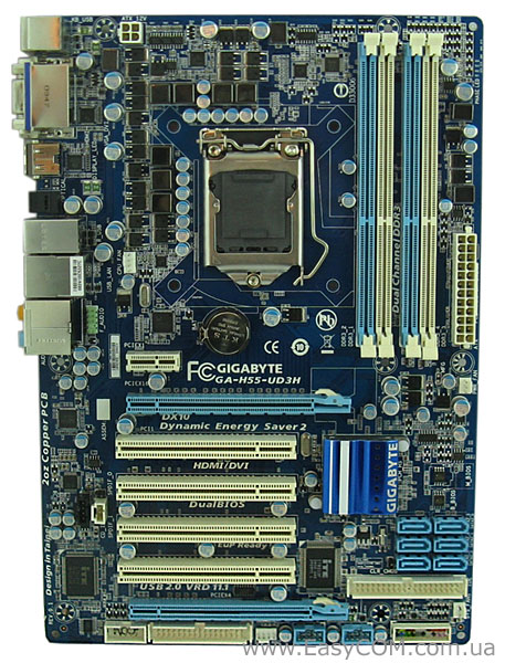
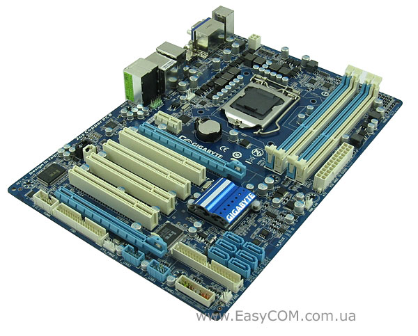
Материнская плата выполнена в полноразмерном форм-факторе ATX на текстолите «фирменного» синего цвета с белыми и голубыми разъемами. Первый взгляд вызывает только положительные эмоции – приятная, не режущая глаз цветовая гамма дает о себе знать. Но давайте «смотреть в корень» и рассмотрим GIGABYTE GA-H55-UD3H более внимательно. Все разъемы для подключения смещены к краям платы и проблем с эргономичной укладкой проводов не возникнет. Немного непривычно расположение батарейки – практически по центру платы, но это просто непривычно и не более.
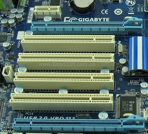
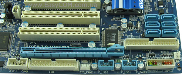
Для установки плат расширения материнская плата оборудована одним разъемом PCI Express x16 2.0, который обслуживается непосредственно центральным процессором, разъемом PCI Express x1, разъемом PCI Express x4 и четырьмя разъемами PCI, которые обслуживает чипсет. Как видите, возможности чипсета в этом плане использованы полностью – у GIGABYTE GA-H55M-UD2H такое было невозможно ввиду использованного форм-фактора microATX. Вообще складывается впечатление, что эту плату делали «для нас» – возможность установки максимально допустимого количества старых добрых и, что не маловажно, очень распространенных плат PCI у нас очень актуальна.
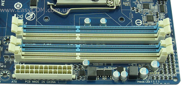
Установка модулей памяти стандарта DDR3 осуществляется в четыре 240-контактных разъема DIMM. Память может работать в двухканальном режиме, максимальный объем одного модуля составляет 4 ГБ. А вот с максимальной частотой работы модулей не все ясно – на сайте компании указана максимальная частота 2200 МГц в режиме разгона, а в руководстве пользователя при тех же условиях только 1666 МГц. Где правда, пока не ясно, поэтому возьмем за основу меньшее значение и лучше потом будем приятно удивлены, чем разочарованы.
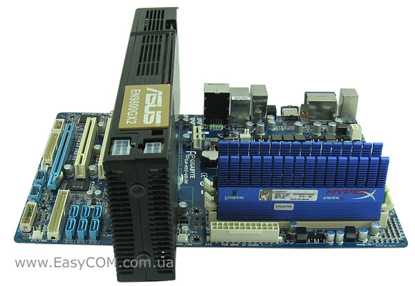
Установка длинной видеокарты проблем не вызывает – защелки памяти не блокируются, никакие разъемы не перекрываются. Все-таки размер платы имеет значение.
Раз уж речь зашла о видеокартах, то стоит отметить поддержку материнской платой технологии ATI CrossFireX, пусть и не в самом производительном режиме х16+х4. Однако слоты PCI Express x16 находятся на таком расстоянии друг от друга, что, вероятнее всего, режим ATI CrossFireX удастся активировать только программным путем, что, вкупе с асимметричностью х16+х4 сводит на нет практичность реализации. Таким образом, второй слот PCI Express x16, использующий только 4 линии чипсета, может быть использован для установки различных контроллеров или расширения рабочего стола с помощью простейшей видеокарты.
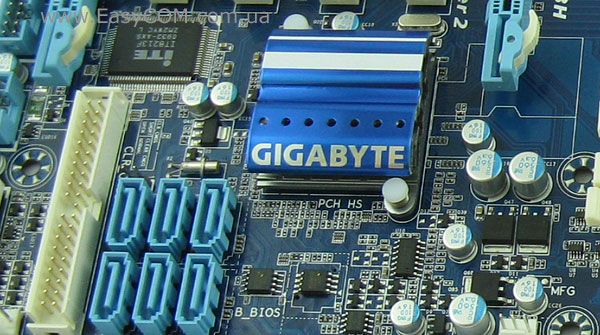
Система охлаждения, примененная на плате, проста и незамысловата – один небольшой низкопрофильный алюминиевый радиатор на чипсете, накрытый декоративной пластиной с названием компании. Вроде бы радиатор и маленький, но, учитывая низкое энергопотребление чипсета Intel H55 Express, он прекрасно справляется с охлаждением – во время тестирования радиатор был чуть теплым. Единственным небольшим недостатком можно считать использование для крепления радиатора ненадежных подпружиненных пластмассовых клипс.

Схема питания, примененная на плате GIGABYTE GA-H55-UD3H, такая же, как на плате GIGABYTE GA-H55M-UD2H – ядро центрального процессора питается четырьмя фазами, которыми управляет ШИМ-контроллер ISL6334, соответствующий стандарту VR 11.1. На материнской плате применена технология энергосбережения Dynamic Energy Saver Advanced, позволяющая отключать часть фаз при низкой нагрузке на процессор. Для удобства пользователей количество активных в данный момент фаз можно определить по светодиодному индикатору, расположенному в верхнем правом углу платы. Питание встроенных в процессор контроллера памяти и видеоядра осуществляется по трехфазной схеме, работой которой управляет ШИМ-контроллер ISL6322G в связке с ITE IT8275E. Модули памяти питаются однофазной схемой. Стоит так же отметить, что на всей плате применены конденсаторы только с твердым электролитом и дроссели с закрытым сердечником. Единственным недостатком системы питания GIGABYTE GA-H55-UD3H можно считать четырехконтактный разъем питания ATX12V, не позволяющий пропускать через себя очень большие токи, поэтому долговременный экстремальный разгон четырехъядерного ЦП на этой плате категорически противопоказан.
Дисковая подсистема состоит из 6 портов SATA II, реализованных силами чипсета, и порта IDE для подключения двух PATA-устройств UltraDMA 133/100/66, выполненного на специализированном контроллере IT8213. Для подключения периферии предлагается использовать 12 портов USB 2.0, контроллер которых встроен в чипсет. Как видите, в отличие от GIGABYTE GA-H55M-UD2H, на плате не реализованы порты e-SATA и IEEE 1394a, а жаль.
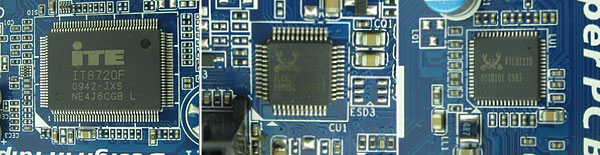
Поддержка COM-порта и интерфейса FDD выполнена на стандартном для таких случаев микроконтроллере ITE IT8720F. Звуковая подсистема реализована на качественном HD-кодеке 8-канального звука Realtek ALC889. Сетевые соединения обслуживает LAN-контроллер Realtek 8111D, который обеспечивает скорость соединения до 1000 Mбит/с.
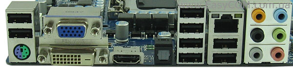
Задняя панель материнской платы GIGABYTE GA-H55-UD3H несет следующие порты:
- порт PS/2 для подключения клавиатуры или мыши;
- VGA и DVI видеовыходы;
- интерфейс высокой четкости HDMI;
- оптический выход S/PDIF;
- восемь разъемов USB;
- разъем RJ45 для сетевых соединений;
- 6 аналоговых разъемов для подключения 8-канального звука.
BIOS
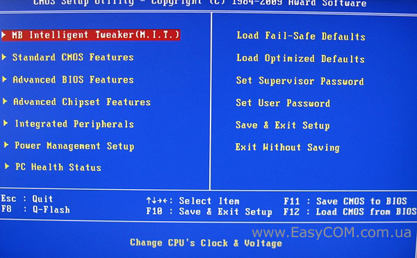
BIOS материнской платы GIGABYTE GA-H55-UD3H основан на коде, написанном компанией Award. Все настройки, необходимые для разгона системы, находятся в самой первой вкладке «MB Intelligent Tweaker(M.I.T.)»
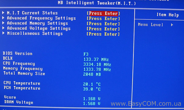
Только зайдя в меню, мы видим 5 подменю и небольшой системный монитор, который показывает нам текущую версию BIOS, частоты шины, процессора и памяти, а также напряжение на ядре процессора и модулях памяти и температуру ЦП и чипсета.
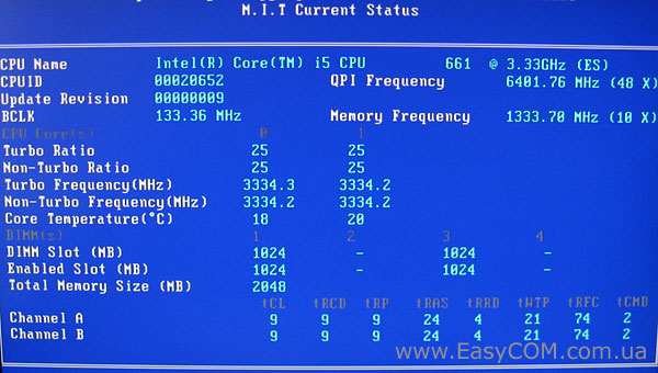
Первое подменю M.I.T. Current Status информационное, показывающее текущие настройки системы.
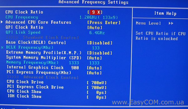
Название второго подменю Advanced Frequency Settings говорит само за себя – здесь собраны все настройки, связанные с частотой.
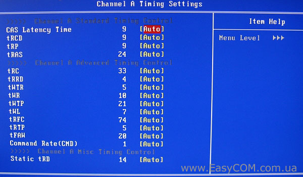
Третье подменю Advanced Memory Settings посвящено настройкам таймингов оперативной памяти.
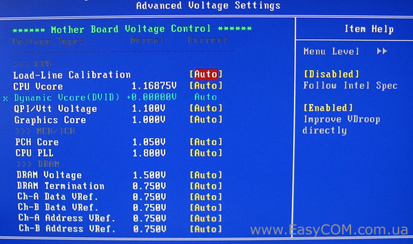
Дальше идет подменю Advanced Voltage Settings. Опять же из названия видно, что в нем собраны настройки, позволяющие изменять напряжения питания практически на всех важных элементах. Значения напряжений можно выбрать самому, а можно поставить в режим «Auto», чтобы система сама выбрала оптимальные значения. Выделение розовым цветом опасных и красным критических значений поможет вам не вывести из строя материнскую плату или комплектующие.
Для удобства и наглядности настраиваемые параметры сведены в таблицу:
|
Параметр |
Название меню |
Диапазон |
Шаг |
|
Множитель частоты процессора |
CPU Clock Ratio |
9-26 |
1 |
|
Множитель шины QPI |
QPI Clock Ratio |
12-48 |
4 |
|
Частота системной шины, МГц |
BCLK Frequency |
100 – 600 МГц |
1МГц |
|
Делитель для памяти |
System Memory Multipllier (SPD) |
6, 8, 10 |
|
|
Частота шины PCI Express |
PCI Express Frequency |
90 – 150 МГц |
1 МГц |
|
Амплитуда сигналов процессора |
CPU Clock Drive |
700 — 1000 мВ |
100 мВ |
|
Амплитуда сигналов шины PCI Express |
PCI Express Clock Drive |
700 — 1000 мВ |
100 мВ |
|
CPU Clock Skew |
0 – 750 пс |
50 пс |
|
|
IOH Clock Skew |
0 – 750 пс |
50 пс |
|
|
Задержки ОЗУ |
CAS Latency, tRCD, tRP, tRAS, tRRD, tWTR, tWR, tWTP, tRFC, tRTP, tRAW, CMD, tRD |
||
|
Напряжение на ядре процессора |
CPU Vcore |
0,50000 — 1,9 В |
0,00625 В |
|
Напряжение на шине QPI/Vtt |
QPI/Vtt Voltage |
1,050 — 1,49 В |
0,02 В |
|
На графическом ядре процессора |
Graphics core |
0,2 – 1,68 В |
0,02 В |
|
Напряжение на чипсете |
PCH Core |
0,95 – 1,5 В |
0,02 В |
|
Напряжение питания ФАПЧ |
CPU PLL |
1,6 — 2,54 В |
0,02 В |
|
Напряжение на модулях памяти |
DRAM Voltage |
1,3 — 2,6 В |
0,02 В |
|
DRAM Termination |
0,45 — 1,55 В |
0,025 В |
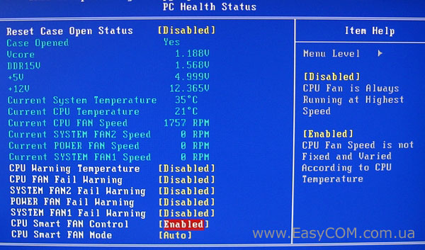
Системный монитор расположен на вкладке «PC Health Status». В нем можно проконтролировать температуры центрального процессора и материнской платы, напряжения на ядре процессора, памяти и линиях питания +5В и +12В, просмотреть скорость вращения вентиляторов, а также задать опасную температуру процессора. К сожалению, технология управления скоростью вращения вентиляторов поддерживается только для процессорного кулера.
Тестирование
Для тестирования материнской платы GIGABYTE GA-H55-UD3H использовалось следующее оборудование.
|
Процессор |
Intel Core i5 661 (LGA1156, 3,33 ГГц, L3 4 МБ) |
|
Кулер |
Scythe Kama Angle Rev. B |
|
Оперативная память |
2x DDR3-2000 1024 МБ Kingston HyperX KHX16000D3T1K3/3GX |
|
Видеокарта |
ASUS EN9800GX2/G/2DI/1G GeForce 9800 GX2 1ГБ GDDR3 PCI-E 2.0 |
|
Жесткий диск |
Seagate Barracuda 7200.12 ST3500418AS, 500 ГБ, SATA-300, NCQ |
|
Оптический привод |
ASUS DRW-1814BLT SATA |
|
Блок питания |
Seasonic SS-650JT Active PFC, 650 Вт, 120 мм вентилятор |
|
Корпус |
CODEGEN M603 MidiTower, 2х 120 мм вентилятора на вдув/выдув |
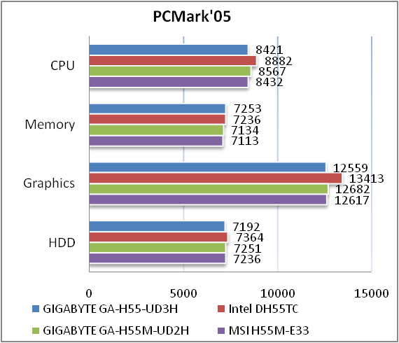
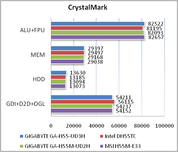
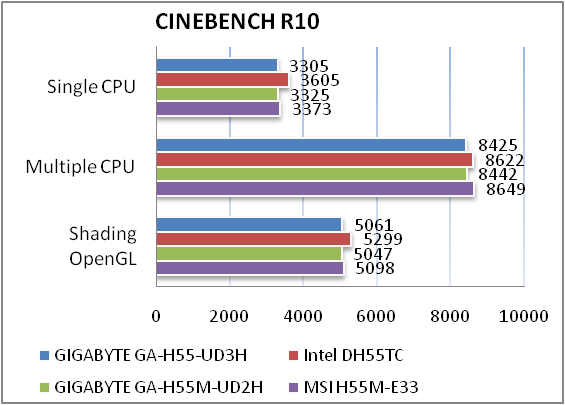
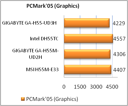
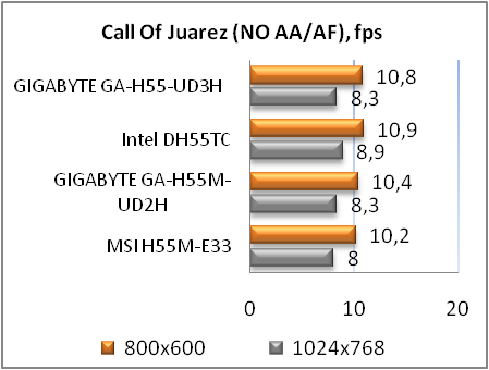
Материнская плата GIGABYTE GA-H55-UD3H имеет уровень производительности примерно такой же, как и ее соперники. Это говорит нам о хорошо отлаженной версии BIOS, но, к сожалению, чуда не произошло, и своими показателями эта материнская плата повторила возможности GIGABYTE GA-H55-UD2H, немного уступив «референсной» плате Intel DH55TC.
Тестирование интегрированного видеоядра
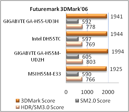
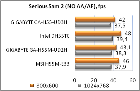
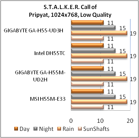
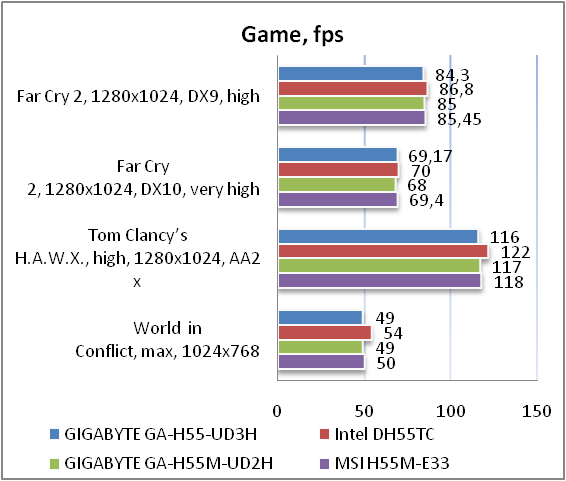
Чуда не произошло и при проверке возможностей встроенной в процессор видеокарты — все повторяется, как и в предыдущих тестах. Но поскольку встроенное видео больше ориентировано на использование в офисных компьютерах или мультимедийных центрах, то его производительности будет вполне достаточно для этих целей.
Возможности разгона
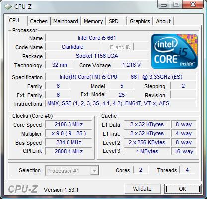
Шину тестового процессора удалось поднять до 234 МГц. Это на 4 МГц выше, чем у GIGABYTE GA-H55-UD2H, и на данный момент является рекордом. Таким образом, плата GIGABYTE GA-H55-UD3H имеет хороший разгонный потенциал в случае установки процессоров на ядре Clarkdale, но особенности системы питания не позволят его применить и с четырехъядерными процессорами на Lynnfield.
Тестирование звукового тракта на основе кодека Realtek ALC889
Общие результаты (RightMark Audio Analyzer)
Режим работы 16-bit, 44,1 kHz
|
Неравномерность АЧХ (в диапазоне 40 Гц — 15 кГц), дБ |
+0.60, -0.28 |
Хорошо |
|
Уровень шума, дБ (А) |
-91.0 |
Очень хорошо |
|
Динамические диапазон, дБ (А) |
91.0 |
Очень хорошо |
|
Гармонические искажения, % |
0.0055 |
Очень хорошо |
|
Гармонические искажения + шум, дБ(A) |
-68.8 |
Средне |
|
Интермодуляционные искажения + шум, % |
0.044 |
Хорошо |
|
Взаимопроникновение каналов, дБ |
-76.2 |
Очень хорошо |
|
Интермодуляции на 10 кГц, % |
0.033 |
Хорошо |
|
Общая оценка |
Очень хорошо |
Режим работы 24-bit, 192 kHz
|
Неравномерность АЧХ (в диапазоне 40 Гц — 15 кГц), дБ |
+0.46, -0.16 |
Очень хорошо |
|
Уровень шума, дБ (А) |
-93.9 |
Очень хорошо |
|
Динамический диапазон, дБ (А) |
93.9 |
Очень хорошо |
|
Гармонические искажения, % |
0.0035 |
Очень хорошо |
|
Гармонические искажения + шум, дБ(A) |
-84.5 |
Хорошо |
|
Интермодуляционные искажения + шум, % |
0.0080 |
Очень хорошо |
|
Взаимопроникновение каналов, дБ |
-75.1 |
Очень хорошо |
|
Интермодуляции на 10 кГц, % |
0.0061 |
Отлично |
|
Общая оценка |
Очень хорошо |
Обвязка звукового кодека выполнена на довольно высоком уровне и в общем зачете аудио-кодек Realtek ALC889 получает оценку «очень хорошо». Качества его звучания будет вполне достаточно для подавляющего большинства пользователей.
Выводы
Материнская плата GIGABYTE GA-H55-UD3H оставила неоднозначное впечатление, особенно если учесть ее минимальные функциональные различия с GIGABYTE GA-H55-UD2H. Но вот эти-то различия и оставили двойственность впечатления. С одной стороны, материнская плата имеет отличные возможности расширения и неплохой разгонный потенциал, прекрасно подойдет как для офисного компьютера, так и домашнего мультимедийного центра или даже игрового компьютера начального или среднего уровня. Но, с другой стороны, плата лишилась таких полезных портов как eSATA и IEEE1394, а ведь найти для них место больших проблем не составляло – ведь на меньшей по размеру плате место нашлось. Так же GIGABYTE GA-H55-UD3H лишилась интерфейса высокой четкости DisplayPort. И все-таки, несмотря на это, продукт получился довольно интересный и своего покупателя обязательно найдет.
Достоинства:
- качественный 8-канальный звуковой кодек;
- три типа видеовыходов (VGA, DVI, HDMI);
- большие возможности расширения;
- высокий разгонный потенциал.
Недостатки:
- отсутствие поддержки FireWire (IEEE1394), eSATA и DisplayPort;
- минимальный комплект поставки;
- использование четырехконтактного разъема питания ATX12V;
- совсем условная поддержка ATI CrossFireX.
Автор: Александра Пацуй
Выражаем благодарность компании GIGABYTE за предоставленную для тестирования материнскую плату.
Выражаем благодарность компаниям Intel, Kingston, Scythe и Sea Sonic за предоставленное для тестового стенда оборудование.
Описание
Характеристики
Технические характеристики материнской платы GigaByte GA-H55-UD3H
Socket
LGA1156
LGA1156
смотреть в других:
Поддерживаемые процессоры
Intel Core i3/Core i5
Чипсет
Intel H55
Intel H55
смотреть в других:
Тип памяти
DDR3 DIMM
DDR3 DIMM
смотреть в других:
Частота памяти
800 — 2133 МГц
Поддержка двухканального режима
есть
Поддержка трехканального режима
нет
Поддержка четырехканального режима
нет
Максимальный объем памяти
Поддержка PCI Express 2.0
есть
Поддержка SLI/CrossFire
CrossFire X
CrossFire X
смотреть в других:
Ethernet
1000 Мбит/с, на основе Realtek RTL8111D
Аудио контроллер
HDA, на основе Realtek ALC889
Основной разъем питания
24-pin
Разъем питания процессора
8-pin
Восстановление BIOS
Award c возможностью аварийного восстановления
Поддержка Hyper-Threading
есть
Физические параметры (нетто)
Размеры (брутто, см)
33x26x7
Отзывы 0
Комментарии 0
Обзоры 0
Гарантия
Материнская плата GigaByte GA-H55-UD3H – цена, наличие, характеристики, отзывы и условия доставки по Москве и России.
Купить материнскую плату GigaByte GA-H55-UD3H можно на сайте KNS Москва заполнив форму заказа в корзине.
Для получения квалифицированной консультации о товаре звоните специалистам компании KNS Москва или задайте вопрос в чате.