

GA-990XA-UD3
User’s Manual
Rev. 1001
12ME-990XAU3-1001R

May 13, 2011
Motherboard
GA-990XA-UD3
May 13, 2011
Motherboard
GA-990XA-UD3
Copyright
© 2011 GIGA-BYTE TECHNOLOGY CO., LTD. All rights reserved.
The trademarks mentioned in this manual are legally registered to their respective owners.
Disclaimer
Information in this manual is protected by copyright laws and is the property of GIGABYTE.
Changes to the specications and features in this manual may be made by GIGABYTE with—
out prior notice. No part of this manual may be reproduced, copied, translated, transmitted, or
published in any form or by any means without GIGABYTE’s prior written permission.
Documentation Classications
In order to assist in the use of this product, GIGABYTE provides the following types of documentations:
For quick set-up of the product, read the Quick Installation Guide included with the product.
For detailed product information, carefully read the User’s Manual.
For product-related information, check on our website at:
http://www.gigabyte.com
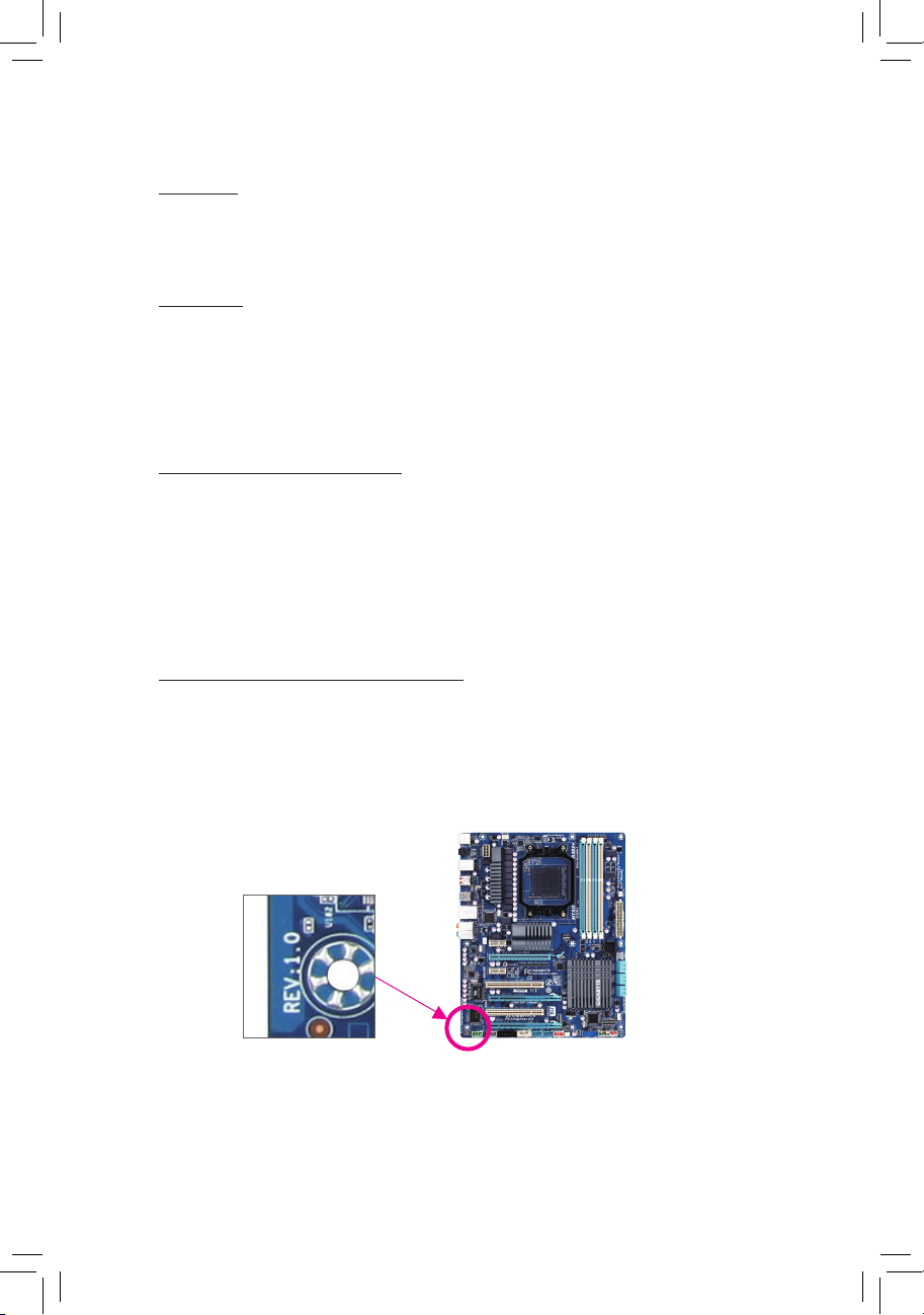
Identifying Your Motherboard Revision
The revision number on your motherboard looks like this: «REV: X.X.» For example, «REV: 1.0»
means the revision of the motherboard is 1.0. Check your motherboard revision before updating
motherboard BIOS, drivers, or when looking for technical information.
Example:

— 4 —
Table of Contents
Box Contents …………………………………………………………………………………………………….6
Optional Items …………………………………………………………………………………………………..6
GA-990XA-UD3 Motherboard Layout ……………………………………………………………………7
GA-990XA-UD3 Motherboard Block Diagram ………………………………………………………..8
Chapter 1 Hardware Installation ………………………………………………………………………….9
1-1 Installation Precautions …………………………………………………………………………9
1-2 Product Specications ………………………………………………………………………… 10
1-3 Installing the CPU and CPU Cooler ……………………………………………………… 13
1-3-1 Installing the CPU ………………………………………………………………………………………13
1-3-2 Installing the CPU Cooler ……………………………………………………………………………15
1-4 Installing the Memory ………………………………………………………………………….16
1-4-1 Dual Channel Memory Conguration ……………………………………………………………16
1-4-2 Installing a Memory …………………………………………………………………………………..17
1-5 Installing an Expansion Card ………………………………………………………………. 18
1-6 Setup of AMD CrossFireX™ Conguration……………………………………………… 19
1-7 Back Panel Connectors ………………………………………………………………………. 20
1-8 Internal Connectors ……………………………………………………………………………. 22
Chapter 2 BIOS Setup ……………………………………………………………………………………..31
2-1 Startup Screen ………………………………………………………………………………….. 32
2-2 The Main Menu …………………………………………………………………………………. 33
2-3 MB Intelligent Tweaker(M.I.T.) ……………………………………………………………… 35
2-4 Standard CMOS Features …………………………………………………………………… 41
2-5 Advanced BIOS Features …………………………………………………………………… 43
2-6 Integrated Peripherals ………………………………………………………………………… 45
2-7 Power Management Setup ………………………………………………………………….. 49
2-8 PC Health Status ……………………………………………………………………………….. 51
2-9 Load Fail-Safe Defaults ………………………………………………………………………. 53
2-10 Load Optimized Defaults …………………………………………………………………….. 53
2-11 Set Supervisor/User Password ……………………………………………………………. 54
2-12 Save & Exit Setup ……………………………………………………………………………… 55
2-13 Exit Without Saving ……………………………………………………………………………. 55

— 5 —
Chapter 3 Drivers Installation …………………………………………………………………………….57
3-1 Installing Chipset Drivers ……………………………………………………………………. 57
3-2 Application Software ………………………………………………………………………….. 58
3-3 Technical Manuals ……………………………………………………………………………… 58
3-4 Contact …………………………………………………………………………………………….. 59
3-5 System …………………………………………………………………………………………….. 59
3-6 Download Center ………………………………………………………………………………. 60
3-7 New Utilities ……………………………………………………………………………………… 60
Chapter 4 Unique Features ……………………………………………………………………………….61
4-1 Xpress Recovery2 ……………………………………………………………………………… 61
4-2 BIOS Update Utilities …………………………………………………………………………. 64
4-2-1 Updating the BIOS with the Q-Flash Utility …………………………………………………….64
4-2-2 Updating the BIOS with the @BIOS Utility …………………………………………………….67
4-3 EasyTune 6 ………………………………………………………………………………………. 68
4-4 Easy Energy Saver ……………………………………………………………………………. 69
4-5 Q-Share ……………………………………………………………………………………………. 71
4-6 SMART Recovery………………………………………………………………………………. 72
4-7 Auto Green ……………………………………………………………………………………….. 73
4-8 Cloud OC …………………………………………………………………………………………. 74
Chapter 5 Appendix …………………………………………………………………………………………75
5-1 Conguring SATA Hard Drive(s) ………………………………………………………….. 75
5-1-1 Conguring SATA Controllers ……………………………………………………………………..75
5-1-2 Installing the SATA RAID/AHCI Driver and Operating System ………………………….81
5-2 Conguring Audio Input and Output ……………………………………………………… 85
5-2-1 Conguring 2/4/5.1/7.1-Channel Audio ………………………………………………………….85
5-2-2 Conguring S/PDIF Out ………………………………………………………………………………87
5-2-3 Enabling the Dolby Home Theater Function …………………………………………………..88
5-2-4 Conguring Microphone Recording ………………………………………………………………89
5-2-5 Using the Sound Recorder ………………………………………………………………………….91
5-3 Troubleshooting…………………………………………………………………………………. 92
5-3-1 Frequently Asked Questions ……………………………………………………………………….92
5-3-2 Troubleshooting Procedure …………………………………………………………………………93
— 6 —
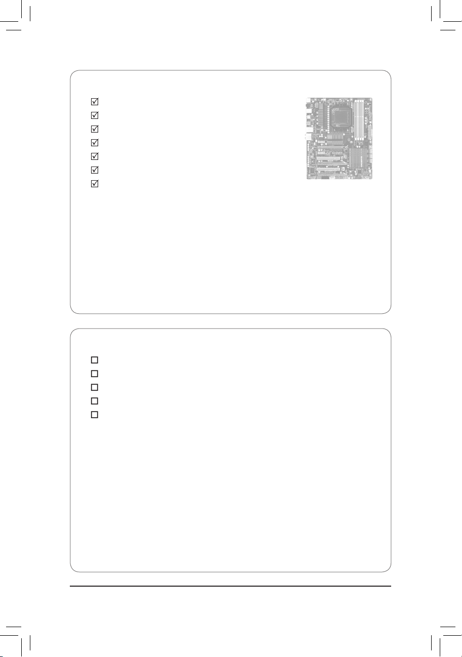
Box Contents
GA-990XA-UD3 motherboard
Motherboard driver disk
User’s Manual
Quick Installation Guide
Four SATA cables
I/O Shield
One 2-Way SLI bridge connector
(Note)
Optional Items
2-port USB 2.0 bracket (Part No. 12CR1-1UB030-5*R)
2-port SATA power cable (Part No. 12CF1-2SERPW-0*R)
COM port cable (Part No. 12CF1-1CM001-3*R)
2-port IEEE 1394a bracket (Part No. 12CF1-1IE008-0*R)
3.5″ Front Panel with 2 USB 3.0/2.0 ports (Part No. 12CR1-FPX582-0*R)
• The box contents above are for reference only and the actual items shall depend on the product package you obtain.
The box contents are subject to change without notice.
• The motherboard image is for reference only.
(Note) To enable NVIDIA SLI technology, you need SLI-supported graphics cards, BIOS, and driver. For more
details, please go to GIGABYTE’s website.
— 7 —
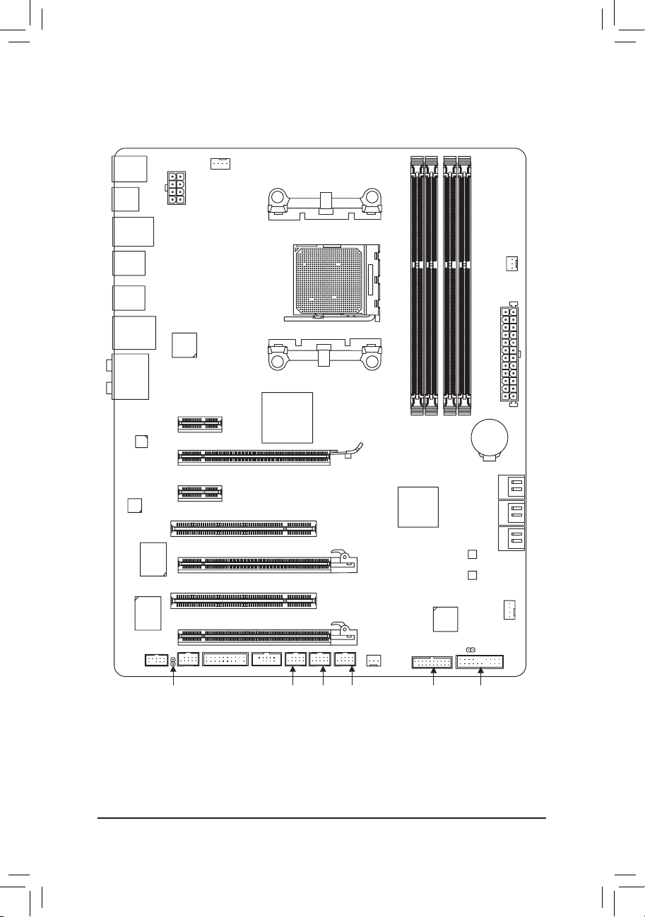
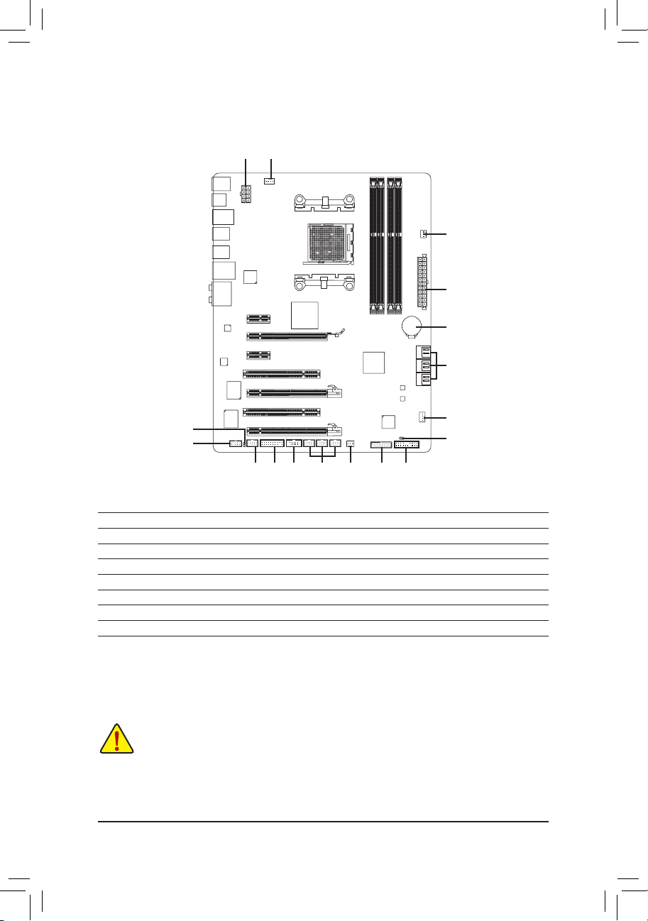
GA-990XA-UD3 Motherboard Layout
KB_MS_USB
CPU_FAN
ATX
GA-990XA-UD3
AUDIO
SYS_FAN1
PCIEX1_1
(Note)
DDR3_4
DDR3_2
ATX_12V
AMD 990X
AMD SB950
PCI1
CODEC
BAT
PCI2
F_USB2
B_BIOS
F_PANEL
M_BIOS
F_USB1
PCIEX16
R_USB
CLR_CMOS
SPDIF_O
Socket AM3+
Realtek
RTL8111E
iTE
IT8720
Etron
EJ168
OPTICAL
USB_1394
R_USB30
USB_LAN
DDR3_3
DDR3_1
PWR_FAN
SATA3_0
SATA3_1
SATA3_2
SATA3_3
SATA3_4
SATA3_5
Etron
EJ168
F_USB30
SYS_FAN2
F_USB3
COMA
F_AUDIO
TPM
F_1394
VIA
VT6308
PCIEX1_2
PCIEX8
PCIEX4
(Note) Due to a hardware limitation, the PCIEX1_1 slot can only accommodate a shorter PCI Express x1
expansion card. For a longer expansion card, use other expansion slots.
— 8 —
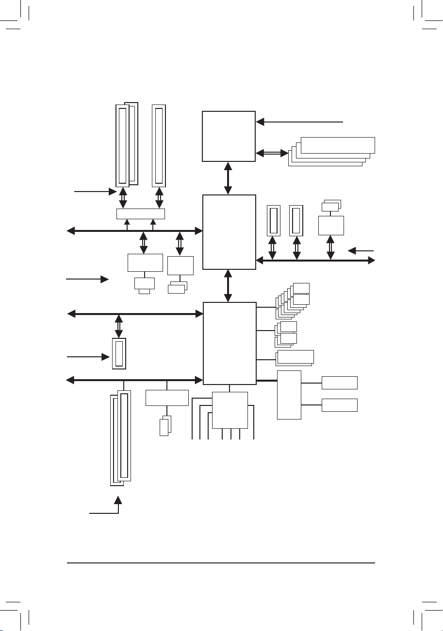
GA-990XA-UD3 Motherboard Block Diagram
AM3+/AM3 CPU
Hyper Transport Bus
AMD 990X
2 PCI
PCI Bus
PCI CLK
(33 MHz)
PCIe CLK
(100 MHz)
PCI Express Bus
CPU CLK+/- (200 MHz)
Dual BIOS
COM Port
LPC
Bus
1 PCI Express x4
DDR3 2000(O.C.)/1866/1600/1333/1066 MHz
6 SATA 6Gb/s
LAN
RJ45
x4
PS/2 KB/Mouse
14 USB 2.0/1.1Ports
iTE
IT8720
Realtek
RTL8111E
x1
2 USB 3.0/2.0
Etron
EJ168
x1
Dual Channel Memory
PCIe CLK
(100 MHz)
1 PCI Express x162 PCI Express x8
Switch
or
x8 x16
x1
2 USB 3.0/2.0
PCI Express Bus
2 PCI Express x1
x1
x1
PCIe CLK
(100 MHz)
Etron
EJ168
VIA VT6308
2 IEEE 1394a
Center/Subwoofer Speaker Out
Line Out
MIC
Line In
S/PDIF Out
Side Speaker Out
Surround Speaker Out
CODEC
AMD SB950
PCI Express Bus
PCIe CLK
(100 MHz)

— 9 — Hardware Installation
1-1 Installation Precautions
The motherboard contains numerous delicate electronic circuits and components which can
become damaged as a result of electrostatic discharge (ESD). Prior to installation, carefully read
the user’s manual and follow these procedures:
• Prior to installation, do not remove or break motherboard S/N (Serial Number) sticker or
warranty sticker provided by your dealer. These stickers are required for warranty validation.
• Always remove the AC power by unplugging the power cord from the power outlet before
installing or removing the motherboard or other hardware components.
• When connecting hardware components to the internal connectors on the motherboard,
make sure they are connected tightly and securely.
• When handling the motherboard, avoid touching any metal leads or connectors.
• It is best to wear an electrostatic discharge (ESD) wrist strap when handling electronic com-
ponents such as a motherboard, CPU or memory. If you do not have an ESD wrist strap,
keep your hands dry and rst touch a metal object to eliminate static electricity.
• Prior to installing the motherboard, please have it on top of an antistatic pad or within an
electrostatic shielding container.
• Before unplugging the power supply cable from the motherboard, make sure the power sup-
ply has been turned off.
• Before turning on the power, make sure the power supply voltage has been set according to
the local voltage standard.
• Before using the product, please verify that all cables and power connectors of your hard-
ware components are connected.
• To prevent damage to the motherboard, do not allow screws to come in contact with the
motherboard circuit or its components.
• Make sure there are no leftover screws or metal components placed on the motherboard or
within the computer casing.
• Do not place the computer system on an uneven surface
.
• Do not place the computer system in a high-temperature environment.
• Turning on the computer power during the installation process can lead to damage to sys-
tem components as well as physical harm to the user.
• If you are uncertain about any installation steps or have a problem related to the use of the
product, please consult a certied computer technician.
Chapter 1 Hardware Installation
Hardware Installation — 10 —
1-2 Product Specications
CPU AM3+ Socket:
— AMD AM3+ FX processors
— AMD AM3 Phenom™ II processors/ AMD Athlon™ II processors
(Go to GIGABYTE’s website for the latest CPU support list.)
Hyper Transport
Bus
5200 MT/s
Chipset
North Bridge: AMD 990X
South Bridge: AMD SB950
Memory 4 x 1.5V DDR3 DIMM sockets supporting up to 32 GB of system memory
* Due to Windows 32-bit operating system limitation, when more than 4 GB of physical
memory is installed, the actual memory size displayed will be less than 4 GB.
Dual channel memory architecture
Support for DDR3 2000 (O.C.)/1866/1600/1333/1066 MHz memory modules
* To support a DDR3 1866 MHz (and above) memory, you must install an AM3+ CPU
rst.
(Go to GIGABYTE’s website for the latest supported memory speeds and memory
modules.)
Audio Realtek ALC889 codec
High Denition Audio
2/4/5.1/7.1-channel
Support for Dolby
®
Home Theater
Support for S/PDIF Out
LAN 1 x Realtek RTL8111E chip (10/100/1000 Mbit)
Expansion Slots 1 x PCI Express x16 slot, running at x16 (PCIEX16)
* For optimum performance, if only one PCI Express graphics card is to be installed,
be sure to install it in the PCIEX16 slot.
1 x PCI Express x16 slot, running at x8 (PCIEX8)
* The PCIEX8 slot shares bandwidth with the PCIEX16 slot. When the PCIEX8 slot
is populated, the PCIEX16 slot will operate at up to x8 mode.
1 x PCI Express x16 slot, running at x4 (PCIEX4)
2 x PCI Express x1 slots
(All PCI Express slots conform to PCI Express 2.0 standard.)
2 x PCI slots
Multi-Graphics
Technology
Support for AMD CrossFireX
™
technology (PCIEX16 and PCIEX8)
* The PCIEX16 slot operates at up to x8 mode when AMD CrossFireX™ is enabled.
Storage Interface South Bridge:
— 6 x SATA 6Gb/s connectors supporting up to 6 SATA 6Gb/s devices
— Support for RAID 0, RAID 1, RAID 5, RAID 10, and JBOD
USB South Bridge:
— Up to 14 USB 2.0/1.1 ports (8 ports on the back panel, 6 ports available
through the internal USB headers)
2 x Etron EJ168 chips:
— Up to 4 USB 3.0/2.0 ports (2 ports on the back panel, 2 ports available
through the internal USB headers)
— 11 — Hardware Installation
IEEE 1394 VIA VT6308 chip:
— Up to 2 IEEE 1394a ports (1 port on the back panel, 1 port available through
the internal IEEE 1394a header)
Internal
Connectors
1 x 24-pin ATX main power connector
1 x 8-pin ATX 12V power connector
6 x SATA 6Gb/s connectors
1 x CPU fan header
2 x system fan headers
1 x power fan header
1 x front panel header
1 x front panel audio header
1 x S/PDIF Out header
3 x USB 2.0/1.1 headers
1 x USB 3.0/2.0 header
1 x IEEE 1394a header
1 x serial port header
1 x clearing CMOS jumper
1 x Trusted Platform Module (TPM) header
Back Panel
Connectors
1 x PS/2 keyboard/mouse port
1 x optical S/PDIF Out connector
1 x IEEE 1394 port
8 x USB 2.0/1.1 ports
2 x USB 3.0/2.0 ports
1 x RJ-45 port
6 x audio jacks (Center/Subwoofer Speaker Out/Rear Speaker Out/Side Speaker
Out/Line In/Line Out/Microphone)
I/O Controller iTE IT8720 chip
Hardware
Monitor
System voltage detection
CPU/System temperature detection
CPU/System/Power fan speed detection
CPU overheating warning
CPU/System/Power fan fail warning
CPU/System fan speed control
* Whether the CPU/system fan speed control function is supported will depend on
the CPU/system cooler you install.
BIOS 2 x 32 Mbit ash
Use of licensed AWARD BIOS
Support for DualBIOS
™
PnP 1.0a, DMI 2.0, SM BIOS 2.4, ACPI 1.0b
Hardware Installation — 12 —
Unique Features Support for @BIOS
Support for Q-Flash
Support for Xpress BIOS Rescue
Support for Download Center
Support for Xpress Install
Support for Xpress Recovery2
Support for EasyTune
* Available functions in EasyTune may differ by motherboard model.
Support for Easy Energy Saver
Support for Smart Recovery
Support for Auto Green
Support for ON/OFF Charge
Support for Cloud OC
Support for 3TB+ Unlock
Support for Q-Share
Bundled
Software
Norton Internet Security (OEM version)
Operating
System
Support for Microsoft
®
Windows 7/Vista/XP
Form Factor ATX Form Factor; 30.5cm x 24.4cm
* GIG ABYTE reser ves the right to make any changes to the product specications and product-related informat ion
without prior notice.
— 13 — Hardware Installation
1-3 Installing the CPU and CPU Cooler
1-3-1 Installing the CPU
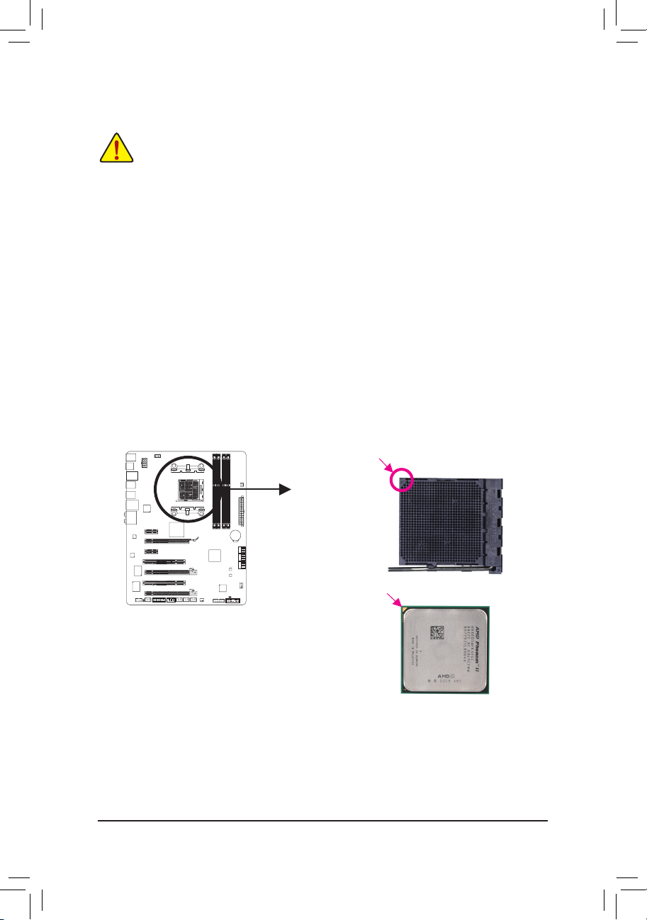
A. Locate the pin one (denoted by a small triangle) of the CPU socket and the CPU.
Read the following guidelines before you begin to install the CPU:
• Make sure that the motherboard supports the CPU.
(Go to GIGABYTE’s website for the latest CPU support list.)
• Always turn off the computer and unplug the power cord from the power outlet before installing
the CPU to prevent hardware damage.
• Locate the pin one of the CPU. The CPU cannot be inserted if oriented incorrectly. (Or you may
locate the notches on both sides of the CPU and alignment keys on the CPU socket.)
• Apply an even and thin layer of thermal grease on the surface of the CPU.
• Do not turn on the computer if the CPU cooler is not installed, otherwise overheating and dam-
age of the CPU may occur.
• Set the CPU host frequency in accordance with the CPU specications. It is not recommended
that the system bus frequency be set beyond hardware specications since it does not meet the
standard requirements for the peripherals. If you wish to set the frequency beyond the standard
specications, please do so according to your hardware specications including the CPU, graphics card, memory, hard drive, etc.
AM3+/AM3 CPU
A Small Triangle Marking
Denotes CPU Pin One
AM3+ Socket
A Smal l Triangle Mark
Denotes Pin One of the
Socket

Hardware Installation — 14 —
B. Follow the steps below to correctly install the CPU into the motherboard CPU socket.
• Before installing the CPU, make sure to turn off the computer and unplug the power cord from the
power outlet to prevent damage to the CPU.
• Do not force the CPU into the CPU socket. The CPU cannot t in if oriented incorrectly. Adjust the
CPU orientation if this occurs.
Step 1:
Completely lift up the CPU socket locking lever.
Step 2:
Align the CPU pin one (small triangle marking) with the triangle mark
on the CPU socket and gently insert the CPU into the socket. Make
sure that the CPU pins t perfectly into their holes. Once the CPU is
positioned into its socket, place one nger down on the middle of the
CPU, lowering the locking lever and latching it into the fully locked
position.
CPU Socket
Locking Lever
— 15 — Hardware Installation
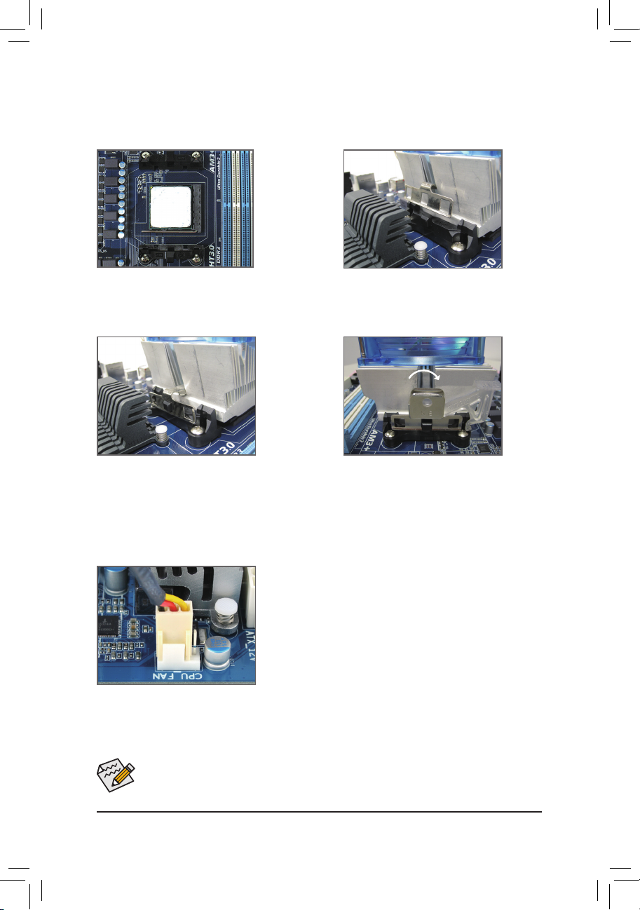
1-3-2 Installing the CPU Cooler
Follow the steps below to correctly install the CPU cooler on the CPU. (The following procedure uses the
GIGABYTE cooler as the example.)
Step 1:
Apply an even and thin layer of thermal grease
on the surface of the installed CPU.
Step 2:
Place the CPU cooler on the CPU.
Step 3:
Hook the CPU cooler clip to the mounting lug
on one side of the retention frame. On the other
side,push straight down on the the CPU cooler
clip to hook it to the mounting lug on the retention frame.
Step 4:
Turn the cam handle from the left side to the
right side (as the picture above shows) to lock
into place. (Refer to your CPU cooler installation
manual for instructions on installing the cooler.)
Step 5:
Finally, attach the power connector of the CPU cooler to the CPU
fan header (CPU_FAN) on the motherboard.
Use extreme care when removing the CPU cooler because the thermal grease/tape between the
CPU cooler and CPU may adhere to the CPU. Inadequately removing the CPU cooler may damage
the CPU.
Hardware Installation — 16 —
1-4 Installing the Memory
Read the following guidelines before you begin to install the memory:
• Make sure that the motherboard supports the memory. It is recommended that memory of the
same capacity, brand, speed, and chips be used.
(Go to GIGABYTE’s website for the latest supported memory speeds and memory modules.)
• Always turn off the computer and unplug the power cord from the power outlet before installing
the memory to prevent hardware damage.
• Memory modules have a foolproof design. A memory module can be installed in only one direction. If you are unable to insert the memory, switch the direction.
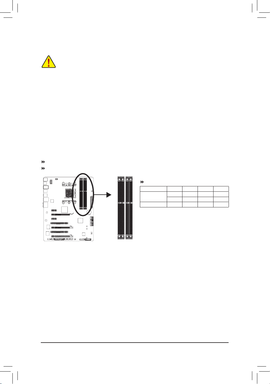
1-4-1 Dual Channel Memory Conguration
This motherboard provides four DDR3 memory sockets and supports Dual Channel Technology. After the
memory is installed, the BIOS will automatically detect the specications and capacity of the memory. Enabling Dual Channel memory mode will double the original memory bandwidth.
The four DDR3 memory sockets are divided into two channels and each channel has two memory sockets as
following:
Channel 0: DDR3_2, DDR3_4
Channel 1: DDR3_1, DDR3_3
Due to CPU limitations, read the following guidelines before installing the memory in Dual Channel mode.
1. Dual Channel mode cannot be enabled if only one DDR3 memory module is installed.
2. When enabling Dual Channel mode with two or four memory modules, it is recommended that
memory of the same capacity, brand, speed, and chips be used and installed in the same colored
DDR3 sockets for optimum performance. when enabling Dual Channel mode with two memory modules, we recommend that you install them in the DDR3_1 and DDR3_2 sockets.
DDR3_4
DDR3_2
DDR3_3
DDR3_1
Dual Channel Memory Congurations Table
(SS=Single-Sided, DS=Double-Sided, «- -«=No Memory)
DDR3_4 DDR3_2 DDR3_3 DDR3_1
Two Modules — — DS/SS — — DS/SS
DS/SS — — DS/SS — —
Four Modules DS/SS DS/SS DS/SS DS/SS
— 17 — Hardware Installation
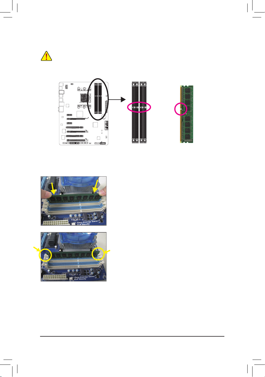
1-4-2 Installing a Memory
Notch
Before installing a memory module, make sure to turn off the computer and unplug the power
cord from the power outlet to prevent damage to the memory module.
DDR3 and DDR2 DIMMs are not compatible to each other or DDR DIMMs. Be sure to install
DDR3 DIMMs on this motherboard.
DDR3 DIMM
A DDR3 memory module has a notch, so it can only t in one direction. Follow the steps below to correctly
install your memory modules in the memory sockets.
Step 1:
Note the orientation of the memory module. Spread the retaining
clips at both ends of the memory socket. Place the memory module
on the socket. As indicated in the picture on the left, place your ngers on the top edge of the memory, push down on the memory and
insert it vertically into the memory socket.
Step 2:
The clips at both ends of the socket will snap into place when the
memory module is securely inserted.
Hardware Installation — 18 —
1-5 Installing an Expansion Card
Read the following guidelines before you begin to install an expansion card:
• Make sure the motherboard supports the expansion card. Carefully read the manual that came
with your expansion card.
• Always turn off the computer and unplug the power cord from the power outlet before installing
an expansion card to prevent hardware damage.
Follow the steps below to correctly install your expansion card in the expansion slot.
1. Locate an expansion slot that supports your card. Remove the metal slot cover from the chassis back panel.
2. Align the card with the slot, and press down on the card until it is fully seated in the slot.
3. Make sure the metal contacts on the card are completely inserted into the slot.
4. Secure the card’s metal bracket to the chassis back panel with a screw.
5. After installing all expansion cards, replace the chassis cover(s).
6. Turn on your computer. If necessary, go to BIOS Setup to make any required BIOS changes for your
expansion card(s).
7. Install the driver provided with the expansion card in your operating system.
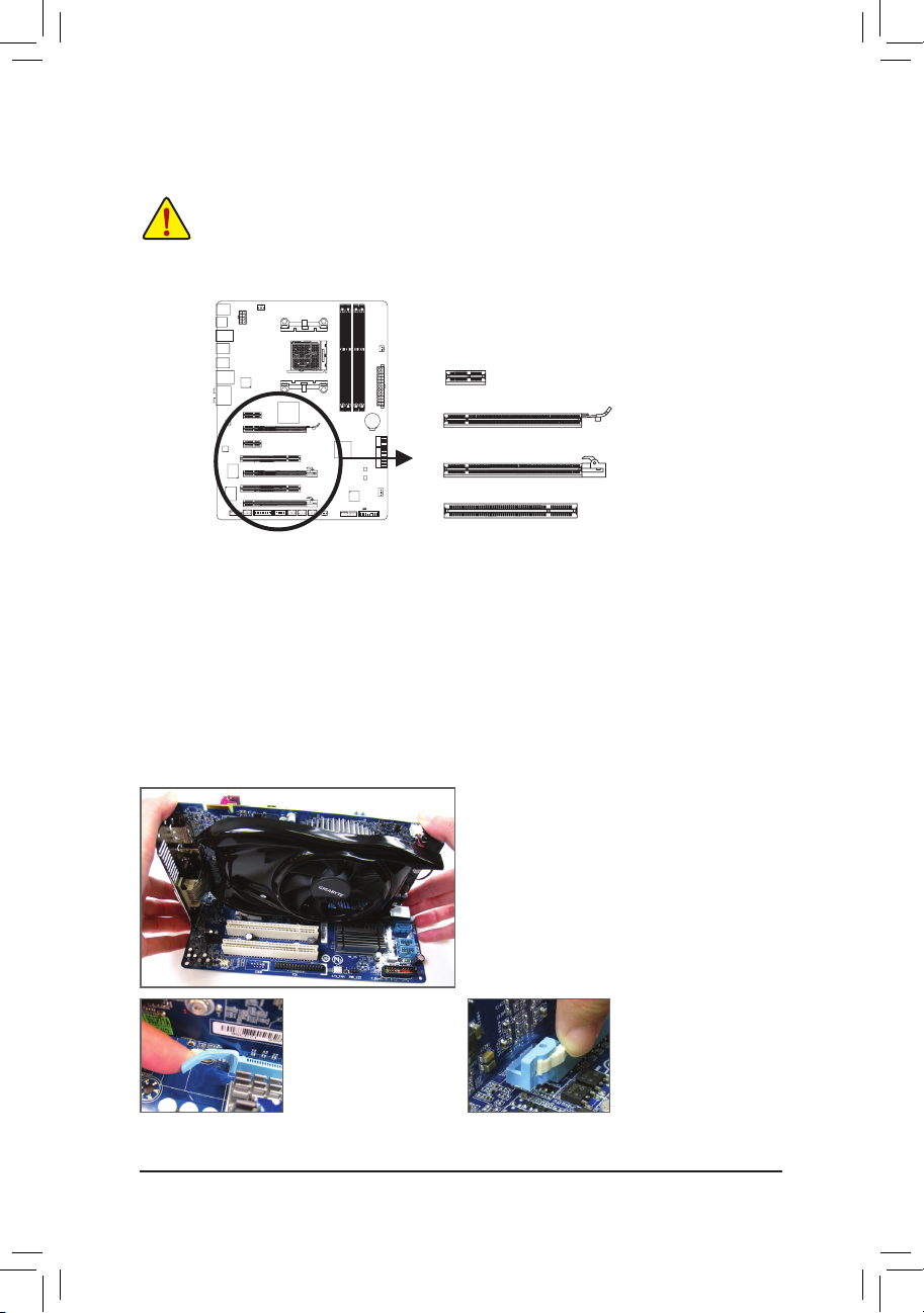
Example: Installing and Removing a PCI Express Graphics Card:
PCI Slot
PCI Express x1 Slot
PCI Express x16 Slot (PCIEX16)
PCI Express x16 Slot (PCIEX8/PCIEX4)
• Installing a Graphics Card:
Gently push down on the top edge of the card until
it is fully inserted into the PCI Express slot. Make
sure the card is securely seated in the slot and
does not rock.
• Removing the Card from
the PCIEX16 Slot:
Gently push back on the
lever on the slot and then
lift the card straight out
from the slot.
• Removing the Card from
the PCIEX8/PCIEX4 Slot:
Press the latch at the end
of the PCI Express slot to
release the card and then
pull the card straight up
from the slot.
— 19 — Hardware Installation
1-6 Setup of AMD CrossFireX™ Conguration
Procedure and driver screen for enabling CrossFireX technology may differ by graphics cards and driver version. Refer to the
manual that came with your graphics cards for more information about enabling CrossFireX technology.
(Note) The bridge connector(s) may be needed or not depending on your graphics cards.
A. System Requirements
— Windows 7, Windows Vista or Windows XP operating system
— A CrossFireX-supported motherboard with two PCI Express x16 slots and correct driver
— Two CrossFireX-ready graphics cards of identical brand and chip and correct driver
— CrossFireX bridge connector(s)
(Note)
— A power supply with sufcient power is recommended (Refer to the manual of your graphics cards for
the power requirement)
B. Connecting the Graphics Cards
Step 1:
Observe the steps in «1-5 Installing an Expansion Card» and install two CrossFireX graphics cards on the
PCIEX16 and PCIEX8 slots.
Step 2:
Insert the CrossFireX bridge connector(s)
(Note)
in the CrossFireX gold edge connectors on top of the two
cards.
Step 3:
Plug the display cable into the graphics card on the PCIEX16 slot.
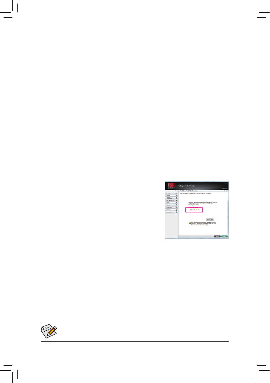
C. Conguring the Graphics Card Driver
To Enable CrossFireX Function:
After installing the graphics card driver in the operating system, go to the Catalyst Control Center. Browse to Performance\AMD CrossFireX Congurations and ensure the Enable CrossFireX™ check box is selected and click
Apply.
Hardware Installation — 20 —
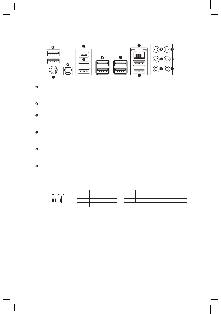
1-7 Back Panel Connectors
USB 2.0/1.1 Port
The USB port supports the USB 2.0/1.1 specication. Use this port for USB devices such as a USB keyboard/mouse, USB printer, USB ash drive and etc.
PS/2 Keyboard/Mouse Port
Use this port to connect a PS/2 mouse or keyboard.
Optical S/PDIF Out Connector
This connector provides digital audio out to an external audio system that supports digital optical audio.
Before using this feature, ensure that your audio system provides an optical digital audio in connector.
IEEE 1394a Port
The IEEE 1394 port supports the IEEE 1394a specication, featuring high speed, high bandwidth and
hotplug capabilities. Use this port for an IEEE 1394a device.
USB 3.0/2.0 Port
The USB 3.0 port supports the USB 3.0 specication and is compatible to the USB 2.0/1.1 specication.
Use this port for USB devices such as a USB keyboard/mouse, USB printer, USB ash drive and etc.
RJ-45 LAN Port
The Gigabit Ethernet LAN port provides Internet connection at up to 1 Gbps data rate. The following
escribes the states of the LAN port LEDs.
Activity LED
Connection/
Speed LED
LAN Port
Activity LED:Connection/Speed LED:
State Description
Orange 1 Gb ps data rate
Green 100 Mbps dat a rate
Off 10 Mbps data rate
State Description
Blinking Dat a transmissi on or receivin g is occurring
Off No data tr ansmission o r receiving is oc curring

— 21 — Hardware Installation
In addition to the default speakers settings, the ~ audio jacks can be recongured to perform
different functions via the audio software. Only microphones still MUST be connected to the
default Mic in jack ( ). Refer to the instructions on setting up a 2/4/5.1/7.1-channel audio con-
guration in Chapter 5, «Conguring 2/4/5.1/7.1-Channel Audio.»
Center/Subwoofer Speaker Out Jack (Orange)
Use this audio jack to connect center/subwoofer speakers in a 5.1/7.1-channel audio conguration.
Rear Speaker Out Jack (Black)
Use this audio jack to connect rear speakers in a 7.1-channel audio conguration.
Side Speaker Out Jack (Gray)
Use this audio jack to connect side speakers in a 4/5.1/7.1-channel audio conguration.
Line In Jack (Blue)
The default line in jack. Use this audio jack for line in devices such as an optical drive, walkman, etc.
Line Out Jack (Green)
The default line out jack. Use this audio jack for a headphone or 2-channel speaker. This jack can be
used to connect front speakers in a 4/5.1/7.1-channel audio conguration.
Mic In Jack (Pink)
The default Mic in jack. Microphones must be connected to this jack.
When removing the cable connected to a back panel connector, rst remove the cable from your •
device and then remove it from the motherboard.
When removing the cable, pull it straight out from the connector. Do not rock it side to side to •
prevent an electrical short inside the cable connector.
Hardware Installation — 22 —
1-8 Internal Connectors
Read the following guidelines before connecting external devices:
• First make sure your devices are compliant with the connectors you wish to connect.
• Before installing the devices, be sure to turn off the devices and your computer. Unplug the
power cord from the power outlet to prevent damage to the devices.
• After installing the device and before turning on the computer, make sure the device cable has
been securely attached to the connector on the motherboard.
1 3
8
14 10 4
4
6
15
2
5
1) ATX_12V
2) ATX
3) CPU_FAN
4) SYS_FAN1/2
5) PWR_FAN
6) SATA3_0/1/2/3/4/5
7) F_PANEL
 F_AUDIO
9) SPDIF_O
10) F_USB1/F_USB2/F_USB3
11) F_USB30
12) F_1394
13) COMA
14) TPM
15) BAT
16) CLR_CMOS
71112
13
9
16
— 23 — Hardware Installation
131
2412
ATX
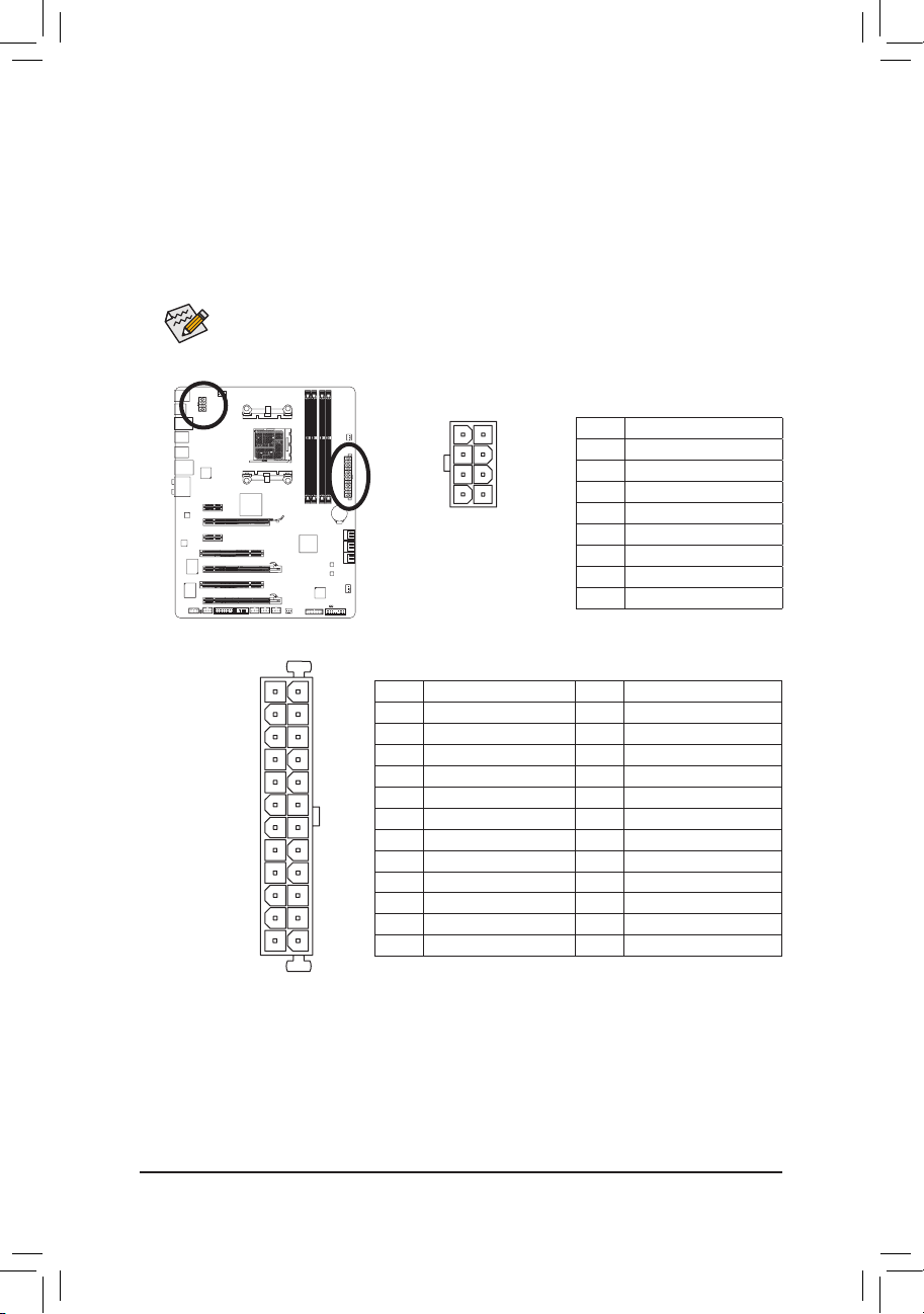
1/2) ATX_12V/ATX (2×4 12V Power Connector and 2×12 Main Power Connector)
With the use of the power connector, the power supply can supply enough stable power to all the
components on the motherboard. Before connecting the power connector, rst make sure the power
supply is turned off and all devices are properly installed. The power connector possesses a foolproof
design. Connect the power supply cable to the power connector in the correct orientation. The 12V
power connector mainly supplies power to the CPU. If the 12V power connector is not connected, the
computer will not start.
To meet expansion requirements, it is recommended that a power supply that can withstand
high power consumption be used (500W or greater). If a power supply is used that does not
provide the required power, the result can lead to an unstable or unbootable system.
ATX_12V:
ATX:
Pin No. Denition Pin No. Denition
1 3.3V 13 3.3V
2 3.3V 14 -12V
3 GND 15 GND
4 +5V 16 PS_ON (soft On/Off)
5 GND 17 GND
6 +5V 18 GND
7 GND 19 GND
8 Power Good 20 -5V
9 5VSB (stand by +5V) 21 +5V
10 +12V 22 +5V
11 +12V (Only for 2×12-pin ATX) 23 +5V (Only for 2×12-pin ATX)
12 3.3V (Only for 2×12-pin ATX) 24 GND (Only for 2×12-pin ATX)
ATX_12V
5
8
1
4
Pin No. Denition
1 GND (Only for 2×4-pin 12V)
2 GND (Only for 2×4-pin 12V)
3 GND
4 GND
5 +12V (Only for 2×4-pin 12V)
6 +12V (Only for 2×4-pin 12V)
7 +12V
8 +12V
Hardware Installation — 24 —
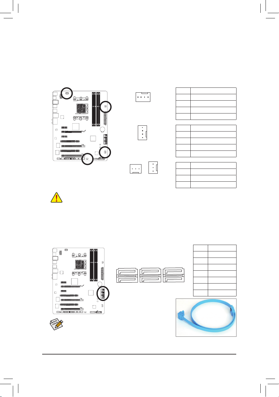
3/4/5) CPU_FAN/SYS_FAN1/SYS_FAN2/PWR_FAN (Fan Headers)
The motherboard has a 4-pin CPU fan header (CPU_FAN), a 4-pin (SYS_FAN1) and a 3-pin (SYS_FAN2)
system fan headers, and a 3-pin power fan header (PWR_FAN). Most fan headers possess a foolproof
insertion design. When connecting a fan cable, be sure to connect it in the correct orientation (the black
connector wire is the ground wire). The motherboard supports CPU fan speed control, which requires the
use of a CPU fan with fan speed control design. For optimum heat dissipation, it is recommended that a
system fan be installed inside the chassis.
• Be sure to connect fan cables to the fan headers to prevent your CPU and system from overheating. Overheating may result in damage to the CPU or the system may hang.
• These fan headers are not conguration jumper blocks. Do not place a jumper cap on the
headers.
1
CPU_FAN
SYS_FAN1
SYS_FAN2
1
1
1
PWR_FAN
CPU_FAN:
SYS_FAN1:
SYS_FAN2/PWR_FAN:
Pin No. Denition
1 GND
2 +12V /Speed Control
3 Sense
4 Speed Control
Pin No. Denition
1 GND
2 +12V /Speed Control
3 Sense
4 Reserve
Pin No. Denition
1 GND
2 +12V
3 Sense
6) SATA3_0/1/2/3/4/5 (SATA 6Gb/s Connectors)
The SATA connectors conform to SATA 6Gb/s standard and are compatible with SATA 3Gb/s and SATA
1.5Gb/s standards. Each SATA connector supports a single SATA device. The AMD SB950 South Bridge
supports RAID 0, RAID 1, RAID 5, RAID 10, and JBOD. Refer to Chapter 5, «Conguring SATA Hard
Drive(s),» for instructions on conguring a RAID array.
Please connect the L-shaped end of
th e SATA cable t o your SATA hard
drive.
• A RAID 0 or RAID 1 conguration requires at least two
hard drives. If more than two hard drives are to be used,
the total number of hard drives must be an even number.
• A RAID 5 conguration requires at least three hard drives.
(The total number of hard drives does not have to be an
even number.)
• A RAID 10 conguration requires four hard drives.
1
1
7
7
SATA3_5
SATA3_3
SATA3_1
SATA3_4
SATA3_2
SATA3_0
Pin No. Denition
1 GND
2 TXP
3 TXN
4 GND
5 RXN
6 RXP
7 GND
— 25 — Hardware Installation
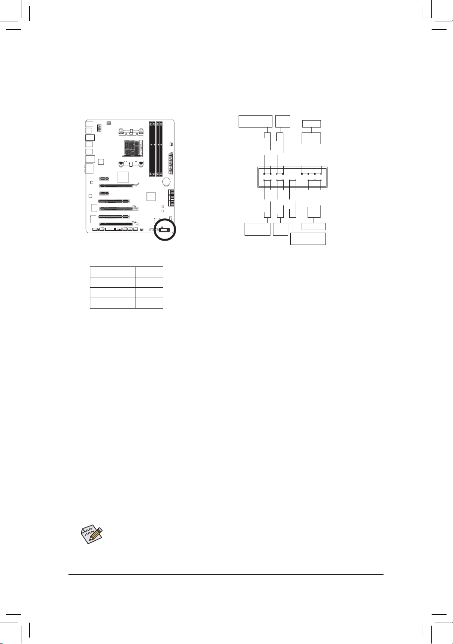
7) F_PANEL (Front Panel Header)
Connect the power switch, reset switch, speaker, chassis intrusion switch/sensor and system status
indicator on the chassis to this header according to the pin assignments below. Note the positive and
negative pins before connecting the cables.
• PW (Power Switch, Red):
Connects to the power switch on the chassis front panel. You may congure the way to turn off your
system using the power switch (refer to Chapter 2, «BIOS Setup,» «Power Management Setup,» for
more information).
• SPEAK (Speaker, Orange):
Connects to the speaker on the chassis front panel. The system reports system startup status by is-
suing a beep code. One single short beep will be heard if no problem is detected at system startup. If
a problem is detected, the BIOS may issue beeps in different patterns to indicate the problem. Refer
to Chapter 5, «Troubleshooting,» for information about beep codes.
• HD (Hard Drive Activity LED, Blue)
Connects to the hard drive activity LED on the chassis front panel. The LED is on when the hard drive
is reading or writing data.
• RES (Reset Switch, Green):
Connects to the reset switch on the chassis front panel. Press the reset switch to restart the computer
if the computer freezes and fails to perform a normal restart.
• CI (Chassis Intrusion Header, Gray):
Connects to the chassis intrusion switch/sensor on the chassis that can detect if the chassis cover
has been removed. This function requires a chassis with a chassis intrusion switch/sensor.
• MSG/PWR (Message/Power/Sleep LED, Yellow/Purple):
Connects to the power status indicator on the chassis front panel. The LED
is on when the system is operating. The LED keeps blinking when the system is in S1 sleep state. The LED is off when the system is in S3/S4 sleep
state or powered off (S5).
The front panel design may differ by chassis. A front panel module mainly consists of power
switch, reset switch, power LED, hard drive activity LED, speaker and etc. When connecting your
chassis front panel module to this header, make sure the wire assignments and the pin assignments are matched correctly.
Power LED
1
2
19
20
CI-
CI+
PWR-
PWR+
MSG-
PW-
SPEAK+
SPEAK-
MSG+
PW+
Message/Power/
Sleep LED
Speaker
Power
Switch
HD-
RES+
HD+
RES-
Hard Drive
Activity LED
Reset
Switch
Chassis Intrusion
Header
System Status LED
S0 On
S1 Blinking
S3/S4/S5 Off
Hardware Installation — 26 —
F_AUDIO (Front Panel Audio Header)
The front panel audio header supports Intel High Denition audio (HD) and AC’97 audio. You may connect
your chassis front panel audio module to this header. Make sure the wire assignments of the module connector match the pin assignments of the motherboard header. Incorrect connection between the module
connector and the motherboard header will make the device unable to work or even damage it.
• The front panel audio header supports HD audio by default. If your chassis provides an AC’97
front panel audio module, refer to the instructions on how to activate AC’97 functionality via
the audio software in Chapter 5, «Conguring 2/4/5.1/7.1-Channel Audio.»
• Audio signals will be present on both of the front and back panel audio connections simultaneously. If you want to mute the back panel audio (only supported when using an HD front panel
audio module), refer to Chapter 5, «Conguring 2/4/5.1/7.1-Channel Audio.»
• Some chassis provide a front panel audio module that has separated connectors on each wire
instead of a single plug. For information about connecting the front panel audio module that
has different wire assignments, please contact the chassis manufacturer.
For HD Front Panel Audio: For AC’97 Front Panel Audio:
Pin No. Denition
1 MIC2_L
2 GND
3 MIC2_R
4 -ACZ_DET
5 LINE2_R
6 GND
7 FAUDIO_JD
8 No Pin
9 LINE2_L
10 GND
Pin No. Denition
1 MIC
2 GND
3 MIC Power
4 NC
5 Line Out (R)
6 NC
7 NC
8 No Pin
9 Line Out (L)
10 NC
9) SPDIF_O (S/PDIF Out Header)
This header supports digital S/PDIF Out and connects a S/PDIF digital audio cable (provided by expan-
sion cards) for digital audio output from your motherboard to certain expansion cards like graphics cards
and sound cards. For example, some graphics cards may require you to use a S/PDIF digital audio cable
for digital audio output from your motherboard to your graphics card if you wish to connect an HDMI
display to the graphics card and have digital audio output from the HDMI display at the same time. For
information about connecting the S/PDIF digital audio cable, carefully read the manual for your expansion card.
Pin No. Denition
1 SPDIFO
2 GND
F_PANEL(NH) F_PANEL
(H61M-D2)
— 27 — Hardware Installation
10) F_USB1/F_USB2/F_USB3 (USB 2.0/1.1 Headers)
The headers conform to USB 2.0/1.1 specication. Each USB header can provide two USB ports via an
optional USB bracket. For purchasing the optional USB bracket, please contact the local dealer.
10
9
2
1
Pin No. Denition
1 Power (5V)
2 Power (5V)
3 USB DX-
4 USB DY-
5 USB DX+
6 USB DY+
7 GND
8 GND
9 No Pin
10 NC
Do not plug the IEEE 1394 bracket (2×5-pin) cable into the USB 2.0/1.1 header. •
Prior to installing the USB bracket, be sure to turn off your computer and unplug the power •
cord from the power outlet to prevent damage to the USB bracket.
When the system is in S4/S5 mode, only the USB ports routed to the F_USB1 header can support the ON/OFF Charge function.
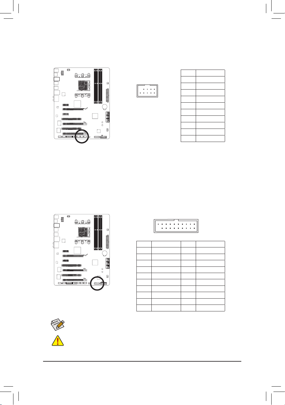
11) F_USB30 (USB 3.0/2.0 Header)
The header conforms to USB 3.0/2.0 specication and can provide two USB ports. For purchasing the
optional 3.5″ front panel that provides two USB 3.0/2.0 ports, please contact the local dealer.
Pin No. Denition Pin No. Denition
1 VBUS 11 D2+
2 SSRX1- 12 D2-
3 SSRX1+ 13 GND
4 GND 14 SSTX2+
5 SSTX1- 15 SSTX2-
6 SSTX1+ 16 GND
7 GND 17 SSRX2+
8 D1- 18 SSRX2-
9 D1+ 19 VBUS
10 NC 20 No Pin
F_AUDIO(H)
F_PANEL(NH) F_PANEL
(H61M-D2)
Hardware Installation — 28 —
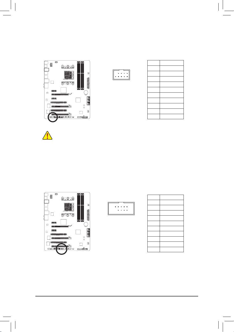
12) F_1394 (IEEE 1394a Header)
The header conforms to IEEE 1394a specication. The IEEE 1394a header can provide one IEEE 1394a
port via an optional IEEE 1394a bracket. For purchasing the optional IEEE 1394a bracket, please contact the local dealer.
• Do not plug the USB bracket cable into the IEEE 1394a header.
• Prior to installing the IEEE 1394a bracket, be sure to turn off your computer and unplug the
power cord from the power outlet to prevent damage to the IEEE 1394a bracket.
• To connect an IEEE 1394a device, attach one end of the device cable to your computer and
then attach the other end of the cable to the IEEE 1394a device. Ensure that the cable is securely connected.
10
9
2
1
Pin No. Denition
1 TPA+
2 TPA-
3 GND-
4 GND
5 TPB+
6 TPB-
7 Power (12V)
8 Power (12V)
9 No Pin
10 GND
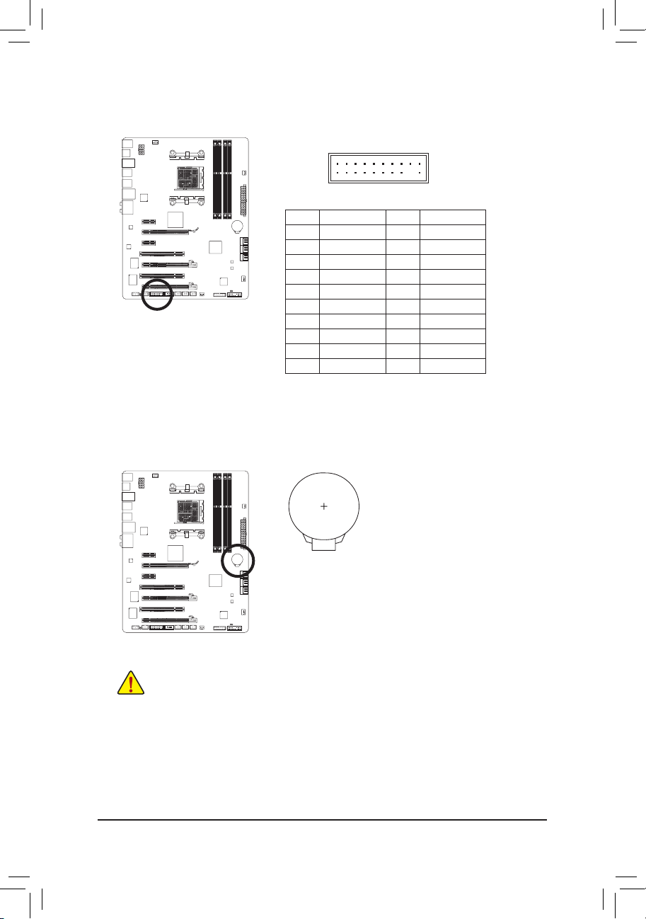
13) COMA (Serial Port Header)
The COM header can provide one serial port via an optional COM port cable. For purchasing the op-
tional COM port cable, please contact the local dealer.
10
9
2
1
Pin No. Denition
1 NDCD-
2 NSIN
3 NSOUT
4 NDTR-
5 GND
6 NDSR-
7 NRTS-
8 NCTS-
9 NRI-
10 No Pin
— 29 — Hardware Installation
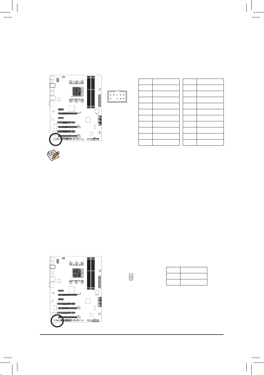
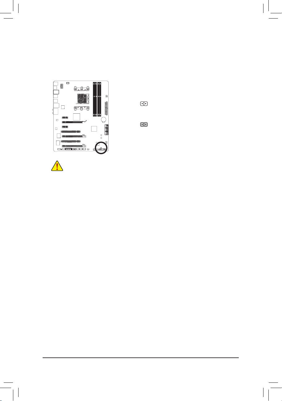
14) TPM (Trusted Platform Module Header)
You may connect a TPM (Trusted Platform Module) to this header.
20
19
2
1
F_AUDIO(H)
DB_PORT
F_PANEL(NH) F_PANEL
(H61M-D2)
Voltage measurement module(X58A-OC)
DIP
1 2 3
1
1
1
1
BIOS Switcher (X58A-OC)
PWM Switch (X58A-OC)
Pin No. Denition Pin No. Denition
1 LCLK 11 LAD0
2 GND 12 GND
3 LFRAME 13 NC
4 No Pin 14 ID
5 LRESET 15 SB3V
6 NC 16 SERIRQ
7 LAD3 17 GND
8 LAD2 18 NC
9 VCC3 19 NC
10 LAD1 20 SUSCLK
15) BAT (Battery)
The battery provides power to keep the values (such as BIOS congurations, date, and time information)
in the CMOS when the computer is turned off. Replace the battery when the battery voltage drops to a
low level, or the CMOS values may not be accurate or may be lost.
You may clear the CMOS values by removing the battery:
Turn off your computer and unplug the power cord.1.
Gently remove the battery from the battery holder and wait for one 2.
minute. (Or use a metal object like a screwdriver to touch the positive
and negative terminals of the battery holder, making them short for 5
seconds.)
Replace the battery. 3.
Plug in the power cord and restart your computer.4.
Always turn off your computer and unplug the power cord before replacing the battery. •
Replace the battery with an equivalent one. Danger of explosion if the battery is replaced with •
an incorrect model.
Contact the place of purchase or local dealer if you are not able to replace the battery by your- •
self or uncertain about the battery model.
When installing the battery, note the orientation of the positive side (+) and the negative side (-) •
of the battery (the positive side should face up).
Used batteries must be handled in accordance with local environmental regulations. •
Hardware Installation — 30 —
16) CLR_CMOS (Clearing CMOS Jumper)
Use this jumper to clear the CMOS values (e.g. date information and BIOS congurations) and reset
the CMOS values to factory defaults. To clear the CMOS values, place a jumper cap on the two pins to
temporarily short the two pins or use a metal object like a screwdriver to touch the two pins for a few
seconds.
Always turn off your computer and unplug the power cord from the power outlet before clear- •
ing the CMOS values.
After clearing the CMOS values and before turning on your computer, be sure to remove the •
jumper cap from the jumper. Failure to do so may cause damage to the motherboard.
After system restart, go to BIOS Setup to load factory defaults (select Load Optimized De- •
faults) or manually congure the BIOS settings (refer to Chapter 2, «BIOS Setup,» for BIOS
congurations).
Open: Normal
Short: Clear CMOS Values
Loading…
-
Page 1: Gigabyte GA-990XA-UD3
GA-990XA-UD3 User’s Manual Rev . 1001 12ME-990XAU3-1001R[…]
-
Page 2: Gigabyte GA-990XA-UD3
May 13, 201 1 Motherboard GA-990XA-UD3 May 13, 201 1 Motherboard GA-990XA-UD3[…]
-
Page 3: Gigabyte GA-990XA-UD3
Copyright © 201 1 GIGA-BYTE TECHNOLOGY CO., L TD. All rights reserved. The trademarks mentioned in this manual are legally registered to their respective owners. Disclaimer Information in this manual is protected by copyright laws and is the property of GIGABYTE. Changes to the specications and features in this manual may be made by GIGABYTE wi[…]
-
Page 4: Gigabyte GA-990XA-UD3
— 4 — T able of Contents Box Contents ……………………………………………………………………………………………………. 6 Optional Items ………………………………………………………………………………………………….. 6 GA-990XA-UD3 Motherboard Layout ………………………….[…]
-
Page 5: Gigabyte GA-990XA-UD3
— 5 — Chapter 3 Drivers Installation ……………………………………………………………………………. 57 3-1 Installing Chipset Drivers ……………………………………………………………………. 57 3-2 Application Software ……………………………………………………………………….[…]
-
Page 6: Gigabyte GA-990XA-UD3
— 6 — Box Contents GA-990XA-UD3 motherboard Motherboard driver disk User’s Manual Quick Installation Guide Four SA T A cables I/O Shield One 2-W ay SLI bridge connector (Note) Optional Items 2-port USB 2.0 bracket (Part No. 12CR1-1UB030-5*R) 2-port SA T A power cable (Part No. 12CF1-2SERPW-0*R) COM port cable (Part No. 12CF1-1CM001-3*R) 2-port[…]
-
Page 7: Gigabyte GA-990XA-UD3
— 7 — GA-990XA-UD3 Motherboard Layout KB_MS_USB CPU_F AN A TX GA-990XA-UD3 AUDIO SYS_F AN1 PCIEX1_1 (Note) DDR3_4 DDR3_2 A TX_12V AMD 990X AMD SB950 PCI1 CODEC BA T PCI2 F_USB2 B_BIOS F_P ANEL M_BIOS F_USB1 PCIEX16 R_USB CLR_CMOS SPDIF_O Socket AM3+ Realtek RTL81 1 1E iTE IT8720 Etron EJ168 OPTICAL USB_1394 R_USB30 USB_LAN DDR3_3 DDR3_1 PWR_F AN SA[…]
-
Page 8: Gigabyte GA-990XA-UD3
— 8 — GA-990XA-UD3 Motherboard Block Diagram AM3+/AM3 CPU Hyper T ransport Bus AMD 990X 2 PCI PCI Bus PCI CLK (33 MHz) PCIe CLK (100 MHz) PCI Express Bus CPU CLK+/- (200 MHz) Dual BIOS COM Port LPC Bus 1 PCI Express x4 DDR3 2000(O.C.)/1866/1600/1333/1066 MHz 6 SA T A 6Gb/s LAN RJ45 x4 PS/2 KB/Mouse 14 USB 2.0/1.1Ports iTE IT8720 Realtek RTL81 1 1E […]
-
Page 9: Gigabyte GA-990XA-UD3
— 9 — Hardware Installation 1- 1 Installation Precautions Th e m ot her bo ar d c on ta in s n um er ou s d el ic at e e le ct ro ni c c ir cu it s a nd comp one nt s w hi ch can become damaged as a result of electrostatic discharge (ESD). Prior to installation, carefully read the user’s manual and follow these procedures: • Prio r to ins[…]
-
Page 10: Gigabyte GA-990XA-UD3
Hardware Installation — 10 — 1- 2 P roduct Sp ecicat ions CPU AM3+ Socket: — AMD AM3+ FX processors — AMD AM3 Phenom ™ II processors/ AMD Athlon ™ II processors (Go to GIGABYTE’s website for the latest CPU support list.) Hyper Transport Bus 520 0 MT/s Chipset North Bridge: AMD 990X South Bridge: AMD SB950 Memory 4 x 1.5V[…]
-
Page 11: Gigabyte GA-990XA-UD3
— 1 1 — Hardware Installation IEEE 1394 VI A V T6 30 8 ch ip: — Up to 2 IEEE 1394a ports (1 port on the back panel, 1 port available through the internal IEEE 1394a header) Internal Connectors 1 x 24-pin A TX main power connector 1 x 8-pin A TX 12V power connector 6 x SA T A 6Gb/s connectors 1 x CPU fan header 2 x system fan hea[…]
-
Page 12: Gigabyte GA-990XA-UD3
Hardware Installation — 12 — Uni que Feat ure s Support for @BIOS Support for Q-Flash Support for Xpress BIOS Rescue Support for Download Center Support for Xpress Install Support for Xpress Recovery2 Support for EasyTune * Available functions in EasyT une may differ by motherboard model. Supp or t for E asy Ener gy S av[…]
-
Page 13: Gigabyte GA-990XA-UD3
— 13 — Hardware Installation 1-3 Installing the CPU and C PU Cooler 1-3 -1 I nst all ing th e CPU A. Locate the pin one (denoted by a small triangle) of the CPU socket and the CPU. Read the following guidelines before you begin to install the CPU: • Make sure that the motherboard supports the CPU. (Go to GIGABYTE’s website for the latest […]
-
Page 14: Gigabyte GA-990XA-UD3
Hardware Installation — 14 — B. Follow the steps below to correctly install the CPU into the motherboard CPU socket. • Before installing the CPU, make sure to turn off the computer and unplug the power cord from the power outlet to prevent damage to the CPU. • Do not force the CPU into the CPU socket. The CPU cannot t in if oriented in[…]
-
Page 15: Gigabyte GA-990XA-UD3
— 15 — Hardware Installation 1-3 -2 I nst all ing th e CPU Cool er Follow the steps below to correctly install the CPU cooler on the CPU. (The following procedure uses the GIGABYTE cooler as the example.) Step 1: Apply an even and thin layer of thermal grease on the surface of the installed CPU. Step 2: Place the CPU cooler on the CPU. Step 3: Ho o[…]
-
Page 16: Gigabyte GA-990XA-UD3
Hardware Installation — 16 — 1- 4 Installing the Memor y Read the following guidelines before you begin to install the memory: • Make sure that the motherboard supports the memory . It is recommended that memory of the same capacity , brand, speed, and chips be used. (Go to GIGABYTE’s website for the latest supported memory speeds and memory[…]
-
Page 17: Gigabyte GA-990XA-UD3
— 17 — Hardware Installation 1- 4 -2 Inst all ing a M emo r y Notch Before installing a memory module, make sure to turn off the computer and unplug the power cord from the power outlet to prevent damage to the memory module. DDR3 and DDR2 DIMMs are not compatible to each other or DDR DIMMs. Be sure to install DDR3 DIMMs on this motherboard. DDR3 D[…]
-
Page 18: Gigabyte GA-990XA-UD3
Hardware Installation — 18 — 1-5 Installing an Expansion Card Read the following guidelines before you begin to install an expansion card: • Make sure the motherboard supports the expansion card. Carefully read the manual that came with your expansion card. • Always turn off the computer and unplug the power cord from the power outlet before in[…]
-
Page 19: Gigabyte GA-990XA-UD3
— 19 — Hardware Installation 1-6 Setup of AMD CrossF ireX ™ Conguration Procedure and driver screen for enabling CrossFireX technology may differ by graphics cards and driver version. Refer to the manual that came with your graphics cards for more information about enabling CrossFireX technology . (Note) The bridge connector(s) may be needed o[…]
-
Page 20: Gigabyte GA-990XA-UD3
Hardware Installation — 20 — 1- 7 Back P anel Connec tors USB 2.0/1.1 Port The USB port supports the USB 2.0/1.1 specication. Use this port for USB devices such as a USB key — board/mouse, USB printer , USB ash drive and etc. PS/2 Keyboard/Mouse Port Use this port to connect a PS/2 mouse or keyboard. Optical S/PDIF Out Connector This connecto[…]
-
Page 21: Gigabyte GA-990XA-UD3
— 21 — Hardware Installation In addition to the default speak ers settings, the ~ audio jacks can be recongured to perform differe nt fun ctio ns via the au dio so ftwa re. On ly mic roph ones s till M UST be co nnec ted to t he default Mic in jack ( ). Refer to the instructions on setting up a 2/4/5.1/7.1-channel audio con- guration in Chapt[…]
-
Page 22: Gigabyte GA-990XA-UD3
Hardware Installation — 22 — 1-8 Internal Connec tors Read the following guidelines before connecting external devices: • First make sure your devices are compliant with the connectors you wish to connect. • Befor e ins tall ing th e dev ices, be sur e to tu rn off th e devi ces a nd you r com pute r . Unplu g the power cord from the powe[…]
-
Page 23: Gigabyte GA-990XA-UD3
— 23 — Hardware Installation DEBUG PO RT G.QBOFM 13 1 24 12 A TX 1/2) A TX_12V/A TX (2×4 12V Power Connector and 2×12 Main Power Connector) W it h th e us e of the pow er con ne ct or, the p ow er s up pl y ca n su pp ly e no ug h st abl e p owe r to all the components on the moth erboard. B efore conne cting the p ower conne ctor, rst make sure[…]
-
Page 24: Gigabyte GA-990XA-UD3
Hardware Installation — 24 — 3/4/5) CPU_F AN/SYS_F AN1/SYS_F AN2/PWR_F AN (Fan Headers) The motherboard has a 4-pin CPU fan header (CPU_F AN), a 4-pin (SYS_F AN1) and a 3-pin (SYS_F AN2) system fan headers, and a 3-pin power fan header (PWR_F AN). Most fan headers possess a foolproof insertion design. When connecting a fan cable, be sure to connect[…]
-
Page 25: Gigabyte GA-990XA-UD3
— 25 — Hardware Installation 7) F_P ANEL (Front Panel Header) C onnec t the p ower s witch , rese t switc h, spe aker, chassi s intr usion s witc h/sen sor an d syst em sta tus indicator on the chassis to this header according to the pin assignments below. Note the positive and negative pins before connecting the cables. • PW (Power Switch, Red):[…]
-
Page 26: Gigabyte GA-990XA-UD3
Hardware Installation — 26 —
 F_AUDIO (Front Panel Audio Header) The front panel audio header supports Intel High Denition audio (HD) and AC’97 a udio. Y ou may connect your chassis front panel audio module to this header. Make sure the wire assignments of the module con — nector match the pin assignments of the motherboard header. Incorr[…]
 -
Page 27: Gigabyte GA-990XA-UD3
— 27 — Hardware Installation 10) F_USB1/F_USB2/F_USB3 (USB 2.0/1.1 Headers) The headers conform to USB 2.0/1.1 specication. Each USB header can provide two USB ports via an optional USB bracket. For purchasing the optional USB bracket, please contact the local dealer . DEBUG PO RT G.QBOFM 10 9 2 1 Pin No. Denition 1 Power (5V) 2 Power (5V) 3 […]
-
Page 28: Gigabyte GA-990XA-UD3
Hardware Installation — 28 — 12) F_1394 (IEEE 1394a Header) The header conforms to IEEE 1394a specication. The IEEE 1394a header can provide one IEEE 1394a port via an optional IEEE 1394a bracket. For purchasing the optional IEEE 1394a bracket, please con- tact the local dealer . • Do not plug the USB bracket cable into the IEEE 1394a header .[…]
-
Page 29: Gigabyte GA-990XA-UD3
— 29 — Hardware Installation 14) TPM (T rusted Platform Module Header) Y ou may connect a TPM (Trusted Platform Module) to this header . 20 19 2 1 F_USB30 F_AUDIO(H) DB_PORT F_ PA NEL(NH) F_ PA NEL (H61M-D2) TPM w/housing V oltage measurement module(X58A-OC) PCIe power connector (S ATA )(X58A-OC) DIP 1 2 3 DIP 1 2 3 DIP 1 2 3 DIP 12 3 1 1 1 1 BIOS […]
-
Page 30: Gigabyte GA-990XA-UD3
Hardware Installation — 30 — 16) CLR_CMOS (Clearing CMOS Jumper) Use this jumper to clear the CMOS values (e.g. date information and BIOS congurations) and reset the CMOS values to factory defaults. T o clear the CMOS values, place a jumper cap on the two pins to temporarily short the two pins or use a metal object like a screwdriver to touch th[…]
-
Page 31: Gigabyte GA-990XA-UD3
— 31 — BIOS Setup BIOS (Ba sic Inpu t and Out put Syst em) reco rds hard ware par ameters of the sy stem in t he CMOS o n the motherboard. Its major functions include conducting the Power-On Self-T est (POST) during system startup, saving sy stem param eters and l oading op erating sy stem, etc . BIOS incl udes a BIO S Setup pro gram that allows th[…]
-
Page 32: Gigabyte GA-990XA-UD3
BIOS Setup — 32 — 2-1 Startup Screen The following screens may appear when the computer boots. A. The LOGO Screen (Default) B. The POST Screen Motherboard Model BIOS V ersion Award Modular BIOS v6.00PG Copyright (C) 1984-201 1, Award Software, Inc. GA-990XA-UD3 F1a . . . . <DEL>: BIOS Setup <F9>: XpressRecovery2 <F12>: Boot Menu &[…]
-
Page 33: Gigabyte GA-990XA-UD3
— 33 — BIOS Setup 2-2 The Main Menu Once you enter the BIOS Setup program, the Main Menu (as shown below) appears on the screen. Use ar- row keys to move among the items and press <Enter> to accept or enter a sub-menu. (Sample BIOS V ersion: F1a) Main Menu Help The on-screen description of a highlighted setup option is displayed on the bottom[…]
-
Page 34: Gigabyte GA-990XA-UD3
BIOS Setup — 34 — The Functions of the <F1 1> and <F12> keys (For the Main Menu Only) F1 1: Save CMOS to BIOS This function allows you to save the current BIOS settings to a prole. Y ou can create up to 8 proles (Prole 1-8) and name each prole. First enter the prole name (to erase the default prole name, use[…]
-
Page 35: Gigabyte GA-990XA-UD3
— 35 — BIOS Setup 2-3 MB Intelligent T weaker(M.I.T .) • Whether the system will work stably with the overclock/overvoltage settings you made is depen — dent on your overall system congurations. Incorrectly doing overclock/overvoltage may result in damage to CPU, chipset, or memory and reduce the useful life of these components. This page is f[…]
-
Page 36: Gigabyte GA-990XA-UD3
BIOS Setup — 36 — CPU NorthBridge Freq. Allows you to alter the North Bridge controller frequency for the installed CPU. The adjustable range is dependent on the CPU being used. Core Performance Boost (Note) A ll ows y ou t o det er min e wh eth er to ena ble the C ore Per for man ce B oos t (C PB) tec hno log y , a CPU performance-boost technology[…]
-
Page 37: Gigabyte GA-990XA-UD3
— 37 — BIOS Setup DRAM Conguration CPU Host Clock Control, CPU Frequency (MHz), Set Memory Clock, Memory Clock The settings under the four items above are synchronous to those under the same items on the MB In- telligent T weaker(M.I.T .) main menu. DCT s Mode Allows you to set memory control mode . Ganged Sets memory control mode to single dual[…]
-
Page 38: Gigabyte GA-990XA-UD3
BIOS Setup — 38 — 1T/2T Command Timing Options are: Auto (default), 1T , 2T . CAS# latency Options are: Auto (default), 5T~14T . RAS to CAS R/W Delay Options are: Auto (default), 2T~19T . Row Precharge Time Options are: Auto (default), 2T~19T . Minimum RAS Active T ime Options are: Auto (default), 8T~40T . T wT r Command Delay Options are: Auto (de[…]
-
Page 39: Gigabyte GA-990XA-UD3
— 39 — BIOS Setup ** DCT s Addr/Cmd T iming ** Addr/Cmd Setup Time Options are: Auto (default), 1/2T , 2T . Addr/Cmd Fine Delay Options are: Auto (default), 0/64~31/64. CS/ODT Setup Time Options are: Auto (default), 1/2T , 2T . CS/ODT Fine Delay Options are: Auto (default), 0/64~31/64. CKE Setup Time Options are: Auto (default), 1/2T , 2T . CKE Fin[…]
-
Page 40: Gigabyte GA-990XA-UD3
BIOS Setup — 40 — DRAM V oltage Control Allows you to set memory voltage. Normal Supplies the memory voltage as required. (Default) 1.025V ~ 2.135V The adjustable range is from 1.025V to 2.135V . Note: Increasing memory voltage may result in damage to the memory or reduce the useful life of the memory . DDR VTT V oltage Control Allows you to set th[…]
-
Page 41: Gigabyte GA-990XA-UD3
— 41 — BIOS Setup Date (mm:dd:yy) Sets the system date. The date format is week (read-only), month, date and year . Select the desired eld and use the up arrow or down arrow key to set the date. Time (hh:mm:ss) Sets the system time. For example, 1 p.m. is 13:0:0. Select the desired eld and use the up arrow or down arrow key to set the time. I[…]
-
Page 42: Gigabyte GA-990XA-UD3
BIOS Setup — 42 — Halt On Allows you to determine whether the sy stem will stop for an error during the POST . All Errors Whenever the BIOS detects a non-fatal error the system boot will stop. No Errors The system boot will not stop for any error. All, But Keyboard The system boot will not stop for a keyboard error but stop for all other errors. (D[…]
-
Page 43: Gigabyte GA-990XA-UD3
— 43 — BIOS Setup 2-5 Advanced BIOS Features AMD C1E Support (Note) Enables or disables the C1E CPU power-saving function in system halt state. When enabled, the power consumption will be reduced during system halt state. Auto If a CP U t hat s uppo rts har dwa re C1 E is in stal led , the BIO S w ill aut omati call y e nabl e t he hardware C1E fun[…]
-
Page 44: Gigabyte GA-990XA-UD3
BIOS Setup — 44 — CPU core 1, 2/3/4/5 (Note) Enables or disables CPU Core 1/2/3/4/5. (Default: Enabled) Hard Disk Boot Priority Species the sequence of loading the operating system from the installed hard drives. Use the up or down arr ow k ey t o se lect a h ard driv e, t hen pres s th e pl us k ey < +> (or < Page Up>) or the minu s[…]
-
Page 45: Gigabyte GA-990XA-UD3
— 45 — BIOS Setup 2-6 Integrated Peripherals OnChip SA T A Controller (AMD SB950 South Bridge) Enables or disables the SAT A controller integrated in the AMD SB950 chip. (Default: Enabled) OnChip SA T A T ype (AMD SB950 South Bridge, SA T A3_0~SA T A3_3 connectors) Congures the operating mode of the in tegrated SA T A3_0~SA T A3_3 controller. Na[…]
-
Page 46: Gigabyte GA-990XA-UD3
BIOS Setup — 46 — Port0 as ESP/Port1 as ESP/Port2 as ESP/Port3 as ESP This option is congurable only when OnChip SA T A T ype is set to AHCI . Enabled will speed up the hot plug detection of the connected SAT A device. (Default: Disabled) Port4 as ESP/Port5 as ESP This option is congurable only when OnChip SA T A T ype is set to AHCI and OnCh[…]
-
Page 47: Gigabyte GA-990XA-UD3
— 47 — BIOS Setup SMART LAN (LAN Cable Diagnostic Function) CMOS Setup Utility-Copyright (C) 1984-2011 A ward Software SMAR T LAN Start detecting at Port….. Part1-2 Status = Open / Length = 0m Part3-6 Status = Open / Length = 0m Part4-5 Status = Open / Length = 0m Part7-8 Status = Open / Length = 0m higf : Move Enter: Select +/-/PU/PD: V alue F10[…]
-
Page 48: Gigabyte GA-990XA-UD3
BIOS Setup — 48 — Onboard Audio Function Enables or disables the onboard audio f unction. (Default: Enabled) If you wish to install a 3rd party add-in audio card instead of using the onboard audio, set this item to Disabled . Onboard 1394 Function Enables or disables the onboard IEEE 1394 function. (Default: Enabled) R_USB30 Controller (Etron EJ168[…]
-
Page 49: Gigabyte GA-990XA-UD3
— 49 — BIOS Setup ACPI Suspend T ype Species the ACPI sleep state when the system enters suspend. S1(POS) Enables the system to enter the ACPI S1 (Power on Suspend) sleep state. In S1 sleep state, the system appears suspended and stays in a low power mode. The system can be resumed at any time. S3(STR) Enables the system to enter the ACPI S3 (Su[…]
-
Page 50: Gigabyte GA-990XA-UD3
BIOS Setup — 50 — (Note) Supported on Windows 7/Vista operating system only . HPET Support (Note) Enables or disables High Precision Eve nt T imer (HPET) for Windows 7/Vista operating system. (Default: Enabled) Power On By Mouse Allows the system to be turned on by a PS/2 mouse wake-up event. Note: T o use this function, you need an A TX power supp[…]
-
Page 51: Gigabyte GA-990XA-UD3
— 51 — BIOS Setup Hardware Thermal Control Enables or disables the CPU overheating protection function. When enabled, the CPU core voltage and ratio will be reduced when the CPU is overheated. (Default: Enabled) Reset Case Open Status Keeps or clears the record of previous chassis intrusion status. Enabled clears the record of previous chassis intr[…]
-
Page 52: Gigabyte GA-990XA-UD3
BIOS Setup — 52 — Current V oltage(V) Vcore/DDR3 1.5V/+3.3V/+12V Displays the current system voltages. Current System/CPU T emperature Displays current system/CPU temperature. Current CPU/SYSTEM/POWER F AN Speed (RPM) Displays current CPU/system/power fan speed. CPU Warning T emperature S e ts t h e wa r ni n g th r es h ol d f or C P U te m pe r a[…]
-
Page 53: Gigabyte GA-990XA-UD3
— 53 — BIOS Setup Press <Enter> on this item and then press the <Y> key to load the safest BIOS default settings. In case system instability occurs, you may try to load Fail-Safe defaults, which are the safest and most stable BIOS settings for the motherboard. 2-9 Load Fail-Safe Defaults CMOS Setup Utility-Copyright (C) 1984-2011 A ward[…]
-
Page 54: Gigabyte GA-990XA-UD3
BIOS Setup — 54 — Press <Enter> on this item and type the password with up to 8 characters and then press <Enter>. Y ou will be requested to conrm the password. T ype the password again and press <Enter>. The BIOS Setup program allows you to specify two separate passwords: Supervisor Password When a system password is set and t[…]
-
Page 55: Gigabyte GA-990XA-UD3
— 55 — BIOS Setup Press <Enter> on this item and press the <Y> key . This saves the changes to the CMOS and exits the BIOS Setup program. Press <N> or <Esc> to return to the BIOS Setup Main Menu. 2-12 Save & Exit Setup Press <Enter> on this item and press the <Y> key. This exits the BIOS Setup without saving […]
-
Page 56: Gigabyte GA-990XA-UD3
BIOS Setup — 56 -[…]
-
Page 57: Gigabyte GA-990XA-UD3
— 57 — Drivers Installation 3-1 Installing Chipset Drivers Chapter 3 Drivers Installation • Before installing the drivers, rst install the operating system. • After installing the operating system, insert the motherboard driver disk into your optical drive. The driver Autorun screen is automatically displayed which looks like that show[…]
-
Page 58: Gigabyte GA-990XA-UD3
Drivers Installation — 58 — 3-2 Application Software This page displays all the utilities and applications that GIGABYTE develops and some free software. Y ou can click the Install button on the right of an item to install it. 3-3 T echnical Manuals This page provides GIGABYTE’s application guides, content descriptions for this driver disk, an[…]
-
Page 59: Gigabyte GA-990XA-UD3
— 59 — Drivers Installation 3-4 Contact For the detailed contact information of the GIGABYTE T aiwan headquarter or worldwide branch ofces, click the URL on this page to link to the GIGABYTE website. 3-5 System This page provides the basic system information.[…]
-
Page 60: Gigabyte GA-990XA-UD3
Drivers Installation — 60 — 3-6 Download Center T o update the BIOS , drivers, or applications, click the Download Ce nter button to link to t he GIGABYTE website. The latest version of the BIOS, drivers, or applications will be displayed. 3-7 New Utilities This page provides a quick link to GIGABYTE’s lately developed utilities for users to i[…]
-
Page 61: Gigabyte GA-990XA-UD3
— 61 — Unique Features Chapter 4 Unique Features 4-1 Xpress Recovery2 Xp r es s R e co v er y 2 i s a u ti l it y t h at a l l ow s y ou to q u i ck l y co m p re s s a nd back up your system data and perform restoration of it. Supporting NTFS, F A T32, and F A T16 le systems, Xpress Recovery2 can back up data on P A T A and SA T A hard drives a[…]
-
Page 62: Gigabyte GA-990XA-UD3
Unique Features — 62 — Step 3: Wh e n pa r ti t io n in g y o ur h a rd d r i ve , m ak e s ur e t o leave unallocated space (10 GB or more is recom- mended; actual size requirements vary , depending on the amount of data) and begin the installation of the operating system. Step 1: Select BACKUP to start backing up your hard drive data. Step 4: Aft[…]
-
Page 63: Gigabyte GA-990XA-UD3
— 63 — Unique Features D. Using the Restore Function in Xpress Recovery2 E. Removing the Backup F . Exiting Xpress Recovery2 Sel ec t RESTORE to re st or e th e ba ck up t o yo ur h ar d dr ive in case the system breaks down. The RESTORE option will not be present if no backup is created before. Select REBOOT to exit Xpress Recovery2. Step 2: After[…]
-
Page 64: Gigabyte GA-990XA-UD3
Unique Features — 64 — Because BIOS ashing is potentially risky , please do it with caution. Inadequate BIOS ashing may result in system malfunction. 4-2 BIOS Update Utilities GI GA B YT E m ot h er b oa r ds p r ov i de t w o un i qu e B IO S u pd a te t o ol s , Q- F la s h ™ an d @ BI O S ™ . GI G AB Y TE Q-Flash and @BIOS are easy-to-[…]
-
Page 65: Gigabyte GA-990XA-UD3
— 65 — Unique Features Q-Flash Utility v2.23 Flash T ype/Size…………………………… MXIC 25L1605/1606 4M Keep DMI Data Enable Load CMOS Default Enable Update BIOS from Drive Save BIOS to Drive Enter : Run hi :Move ESC:Reset F10:Power Off B. Updating the BIOS When updatin g the BIOS, ch oose the loc ation where t he BIOS le is saved. T[…]
-
Page 66: Gigabyte GA-990XA-UD3
Unique Features — 66 — Step 4: Press <Esc> and then <Enter> to exit Q-Flash and reboot the system. As the system boots, you should see the new BIOS version is present on the POST screen. Step 5: During the POST , press <Delete> to enter BIOS Setup. Select Load Optimized Defaults and press <Enter> to load BIOS defaults. Syste[…]
-
Page 67: Gigabyte GA-990XA-UD3
— 67 — Unique Features 4-2-2 Updating the BIOS with the @BIOS Utility A. Before Y ou Begin 1. In Windows, close all applications and TSR (T erminate and Stay Resident) programs. This helps prevent unexpected failures when performing a BIOS update. 2. Dur ing the B IOS upda te proc ess, ens ure the I nternet connect ion is st able an d do NOT inter […]
-
Page 68: Gigabyte GA-990XA-UD3
Unique Features — 68 — Available functions in EasyTune 6 may differ by motherboard model. Grayed-out area(s) indicates that the item is not congurable or the function is not supported. Incorrectly doing overclock/overvoltage may result in damage to the hardware components such as CPU, chipset, and memory and reduce the useful life of these compo[…]
-
Page 69: Gigabyte GA-990XA-UD3
— 69 — Unique Features 4-4 Easy Energy Saver GIGABYTE Easy Energy Saver is a revolutionary technology that delivers unparalleled power savings with a click of the button. Featuring an advanced proprietary software design, GIGABYTE Easy Energy Saver is able to provide exceptional power savings and enhanced power efciency without sacricing comp[…]
-
Page 70: Gigabyte GA-990XA-UD3
Unique Features — 70 — C. Stealth Mode In Stealth Mode, the system continues t o work with the user-dened power saving settings, even after the system is restarted. Re-enter the application only if you want to make any changes or completely close the application. (Note 1) Maximize system power saving with Dynamic CPU Frequency Function; system p[…]
-
Page 71: Gigabyte GA-990XA-UD3
— 71 — Unique Features 4-5 Q-Share Q-Share is an easy and convenient data sharing too l. After conguring your LAN connection settings and Q-Share, you are able to share your data with computers on the same network, making full use of Internet resources. Directions for using Q-Share After installing Q-Share from the motherboard driver disk, go to[…]
-
Page 72: Gigabyte GA-990XA-UD3
Unique Features — 72 — 4-6 SMART Recovery With SMART Recovery , users can quickly create backups of changed data les (Note 1) or copy les from a spe — cic backup on P A T A and SA T A hard drives (partitioned on NTFS le system) in Windows 7/V ista. Instructions for copying les/folders from a backup: T o b r ow se t hr ou g h yo ur b […]
-
Page 73: Gigabyte GA-990XA-UD3
— 73 — Unique Features 4-7 Auto Green Auto Green is an easy-to-use tool that provides users with simple options to enable system power savings via a Bluetooth cell phone. When the phone is out of the range of the computer’s Bluetooth receiver , the sys- tem will enter the specied power saving mode. Sele cting a sy stem e ner gy s aving mode[…]
-
Page 74: Gigabyte GA-990XA-UD3
Unique Features — 74 — 4-8 Cloud OC Cloud OC (Note 1) is an easy-to-use overclocking utility designed for system overclock- ing via virtually any Internet-conn ected device, such as a smart pho ne, iPhone, note — book PC, etc. By simply connecting to an Internet browser via LAN, wireless LAN, or Bluetooth (Note 2) and logging in to the Cloud OC ser[…]
-
Page 75: Gigabyte GA-990XA-UD3
— 75 — Appendix Chapter 5 Appendix 5-1 Conguring SA T A Hard Drive(s) T o congure SA T A hard drive(s), follow the steps below: A. Install SA T A hard drive(s) in your computer . B. Congure SA T A controller mode in BIOS Setup. C. Congure a RAID array in RAID BIOS. (Note 1) D. Install the SA T A RAID/AHCI driver (Note 2) and operating s[…]
-
Page 76: Gigabyte GA-990XA-UD3
Appendix — 76 — The BIOS Setup menus described in this section may differ from the exact settings for your moth- erboard. The actual BIOS Setup menu options you will see shall depend on the motherboard you have and the BIOS version. B. Conguring SA T A controller mode in BIOS Setup Make sure to congure the SA T A controller mode correctly in […]
-
Page 77: Gigabyte GA-990XA-UD3
— 77 — Appendix C. Conguring RAID set in RAID BIOS Enter the RAID BIOS setup utility to congure a RAID array . Skip this step and proceed with the installation of Windows operating system for a non-RAID conguration. Step 1: After the POST memory test begins and before the operating system boot begins, look for a message which says «Pr[…]
-
Page 78: Gigabyte GA-990XA-UD3
Appendix — 78 — In the LD Dene Menu , use the up or down arrow key to move to an item for further conguration (Figure 5). Figure 4 Figure 5 [ Keys Available ] Option ROM Utility (c) 2011 Advanced Micro Devices, Inc. [LDDeneMenu] [ h ] Up [ i ] Down [PaUp/PaDn] Switch Page [Space] Change Option [Ctrl+Y] Save [ESC] Exit [ Keys Av[…]
-
Page 79: Gigabyte GA-990XA-UD3
— 79 — Appendix In the following procedure, we’ll create RAID 0 as an example. 1. Under the RAID Mode section, press the <SP ACE> key to select RAID 0 . 2. Set the Stripe Block size. 64 KB is the default. 3. Under the Drives Assignments section, press the up or down arrow key to highlight a drive. 4. Press the <SP ACE> key or <Y[…]
-
Page 80: Gigabyte GA-990XA-UD3
Appendix — 80 — Delete an Array The Delete Array menu option allows for deletion of disk array assignments. Deleting an existing disk array could result in loss of data. Record all array information including the array type, the disk members, and stripe block size in case you wish to undo a deletion. 1. T o delete an array , press <3> in the […]
-
Page 81: Gigabyte GA-990XA-UD3
— 81 — Appendix A. Installing Windows 7/Vista (The following instructions use Windows 7 as the example operating system.) 5-1-2 Installing the SA T A RAID/AHCI Driver and Operating System With the correct BIOS settings, you are ready to install Windows 7/Vista/XP . Step 1: Boot from the Windows 7/Vista setup disk and perform standard OS installatio[…]
-
Page 82: Gigabyte GA-990XA-UD3
Appendix — 82 — B. Installing Windows XP Before installing Windows XP , connect a USB oppy disk drive to your computer rst because you need to in — stall the SA T A RAID/AHCI driver from a oppy disk that contains the driver during the OS installation. Without the driver , the hard drive(s) may not be recognized during the Windows setup pro[…]
-
Page 83: Gigabyte GA-990XA-UD3
— 83 — Appendix Step 2: Insert the oppy disk containing the SAT A RAID/AHCI driver and press <Enter>. Then a controller menu simi — lar to that in Figure 3 will appear. Select AMD AHCI Compatible RAID Controller-x86 platform and press <Enter>. Figure 3 Refer to the following for installing the driver during the Windows setup process.[…]
-
Page 84: Gigabyte GA-990XA-UD3
Appendix — 84 — Rebuilding an Array: Rebuilding is the process of restoring data to a hard drive from other drives in the array . Rebuilding applies only to fault-tolerant arrays such as RAID 1, RAID 5, or RAID 10. T o replace the old drive, make sure to use a new drive of equal or greater capacity . The procedures below assume a new drive is added[…]
-
Page 85: Gigabyte GA-990XA-UD3
— 85 — Appendix 5-2-1 Conguring 2/4/5.1/7.1-Channel Audio The motherboard provides six aud io jacks on the back pan el w hi ch s upp or t 2/ 4/ 5.1 /7 .1 -ch an ne l (Note) au dio . The picture to the right shows the default audio jack assignments. The integrated HD (High Definition) audio provides jack retasking capability that allows the user […]
-
Page 86: Gigabyte GA-990XA-UD3
Appendix — 86 — Step 2: Connect an audio device to an audio jack. The The cur- rent connected device is dialog box appears. Select the device according to the type of device you connect. Then click OK . Step 3: On the Speakers s creen, click t he Spe aker Co ngur a — tion tab. In the Speaker Conguration list, select Stereo , Quadraphonic , 5.[…]
-
Page 87: Gigabyte GA-990XA-UD3
— 87 — Appendix (Note) Enter the Digital Output(Optical) screen to congure further settings if you use the S/PDIF Out connector(s) on the back panel for digital audio output or enter the Digital Output screen if you use the internal S/PDIF Out connector (SPDIF_O) for digital audio output. 5-2-2 Conguring S/PDIF Out The S/PDIF Out jack can tra[…]
-
Page 88: Gigabyte GA-990XA-UD3
Appendix — 88 — 5-2-3 Enabling the Dolby Home Theater Function Before D olby Hom e Theater is enabled , you get only 2-c hannel p layback output ( from the front speakers) when playing 2-channel stereo sources. Y ou must play 4-, 5.1-, or 7.1- chan- nel content to get 4-, 5.1-, or 7.1- channel audio effects. With Dolby Home Theater enabled, 2-chann[…]
-
Page 89: Gigabyte GA-990XA-UD3
— 89 — Appendix 5-2-4 Conguring Microphone Recording Step 1: After installing the audio driver , the HD Audio Manager icon will appear in the notication area. Double-click the icon to access the HD Audio Manager . Step 2: Connect your microphone to the Mic in jack (pink) on th e ba c k pa ne l o r th e M ic i n j ac k ( pi nk ) o n th e f ro […]
-
Page 90: Gigabyte GA-990XA-UD3
Appendix — 90 — Step 5: After co mpletin g the set tings a bove, cl ick Start , p oint to All Programs , point to Accessories , and then click Sound Recorder to begin the sound recording. Step 1: Loca te t he i con in th e not ifi cati on a rea a nd ri ght — click on this icon. Select Recording Devices . Step 2: On the Recording tab, ri ght-click o[…]
-
Page 91: Gigabyte GA-990XA-UD3
— 91 — Appendix Step 4: Now you can access the HD Audio Manager to cong — ure Stereo Mix and use Sound Recorder to record the sound. 5-2-5 Using the Sound Recorder A. Recording Sound 1. Make sure you have connected the sound input device (e.g. microphone) to the computer. 2. T o record the audio, click the Start Recording button . 3. T o stop re[…]
-
Page 92: Gigabyte GA-990XA-UD3
Appendix — 92 — 5-3 T roubleshooting 5-3-1 Frequently Asked Questions T o read more F AQs for your motherboard, please go to the Support & DownloadsF AQ page on GIGABYTE’s website. Q: In the BIOS Setup program, why are some BIOS options missing? A: Some advanced options are hidden in the BIOS Setup program. Press <Delete> to enter B[…]
-
Page 93: Gigabyte GA-990XA-UD3
— 93 — Appendix 5-3-2 T roubleshooting Procedure If you encounter any troubles during system startup, follow the troubleshooting procedure below to solve the problem. ST ART A Turn off the power . Remove all peripherals, connecting cables, and power cord etc. Isolate the short circuit. Secure the CPU cooler on the CPU. Connect the CPU cooler power […]
-
Page 94: Gigabyte GA-990XA-UD3
Appendix — 94 — If the procedure above is unable to solve your problem, contact the place of purchase or local deal- er for help. Or go to the Support & DownloadsT echnical Support page to submit your question. Our customer service staff will reply you as soon as possible. The power supply , CPU or CPU socket might fail. The keyboard or keyboa[…]
-
Page 95: Gigabyte GA-990XA-UD3
— 95 — Appendix[…]
-
Page 96: Gigabyte GA-990XA-UD3
Appendix — 96 -[…]
-
Page 97: Gigabyte GA-990XA-UD3
— 97 — Appendix[…]
-
Page 98: Gigabyte GA-990XA-UD3
Appendix — 98 -[…]
-
Page 99: Gigabyte GA-990XA-UD3
— 99 — Appendix Contact Us • GIGA-BYTE TECHNOLOGY CO., L TD. Address: No.6, Bao Chiang Road, Hsin-Tien Dist., New T aipei City 231,T aiwan TEL: +886-2-8912-4000 F AX: +886-2-8912-4003 T ech. and Non-T ech. Support (Sales/Marketing) : http://ggts.gigabyte.com.tw WEB address (English): http://www .gigabyte.com WEB address (Chinese): http://www .gig[…]
-
Page 100: Gigabyte GA-990XA-UD3
Appendix — 100 — • G.B.T . TECHNOLOGY TRADING GMBH — Germany WEB address : http://www .gigabyte.de • G.B.T . TECH. CO., L TD. — U.K. WEB address : http://www .giga-byte.co.uk • Giga-Byte T echnology B.V . — The Netherlands WEB address : http://www .giga-byte.nl • GIGABYTE TECHNOLOGY FRANCE — France WEB address : http://www .gigabyte.fr • […]
GIGABYTE
GA-990XA-UD3 (rev. 1.x) Инструкция по применению
Популярность:
1855 просмотры
Подсчет страниц:
40 страницы
Тип файла:
Размер файла:
12.15 Mb
Предлагаем вам документ Инструкция по применению на GIGABYTE GA-990XA-UD3 (rev. 1.x): PDF файл 12.15 Mb, 40 страниц.
Инструкция по применению GA-990XA-UD3 (rev. 1.x) — читать онлайн или скачать бесплатно. Также, вы можете задать любой вопрос про GIGABYTE GA-990XA-UD3 (rev. 1.x).
Скачать файл Инструкция по применению GIGABYTE GA-990XA-UD3 (rev. 1.x)
Размер файла: 12.15 Mb
Кол-во страниц: 40
Просмотров: 1854
Тип файла: Portable Document Format (PDF)

Читать онлайн GIGABYTE GA-990XA-UD3 (rev. 1.x) Инструкция по применению

GA-990XA-UD3 R5
User’s Manual
Rev. 1001
12ME-990X3R5—1001R
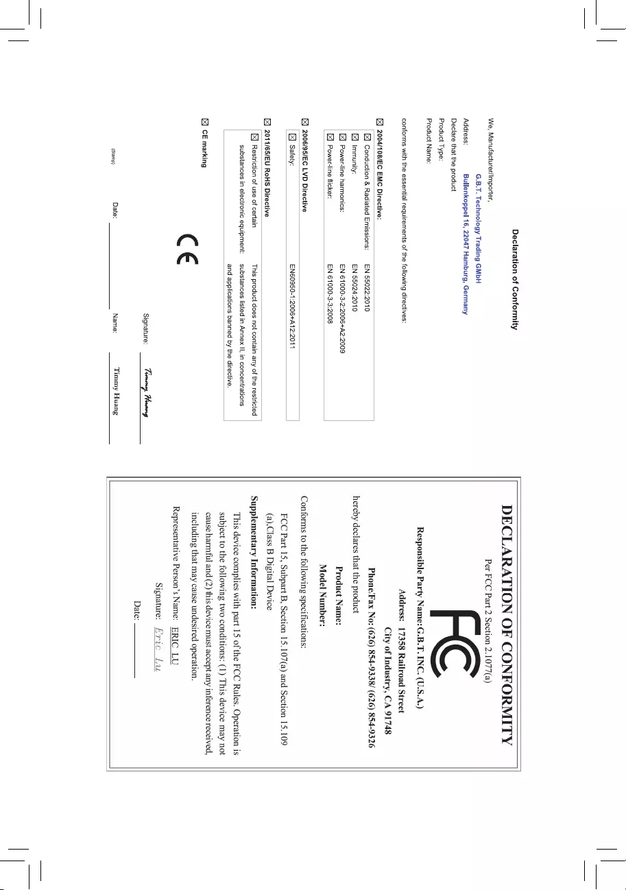
Motherboard
GA-990XA-UD3 R5
Feb. 1, 2015
Feb. 1, 2015
Motherboard
GA-990XA-UD3 R5
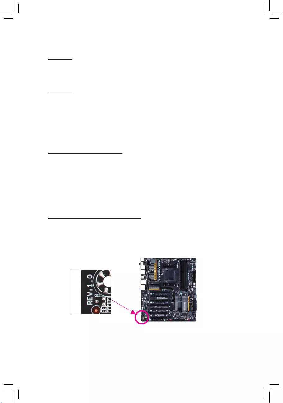
Copyright
© 2015 GIGA-BYTE TECHNOLOGY CO., LTD. All rights reserved.
The trademarks mentioned in this manual are legally registered to their respective owners.
Disclaimer
Information in this manual is protected by copyright laws and is the property of GIGABYTE.
Changes to the specications and features in this manual may be made by GIGABYTE
without prior notice.
No part of this manual may be reproduced, copied, translated, transmitted, or published in
any form or by any means without GIGABYTE’s prior written permission.
Documentation Classications
In order to assist in the use of this product, GIGABYTE provides the following types of docu—
mentations:
For quick set-up of the product, read the Quick Installation Guide included with the product.
For detailed product information, carefully read the User’s Manual.
For product-related information, check on our website at: http://www.gigabyte.com
Identifying Your Motherboard Revision
The revision number on your motherboard looks like this: «REV: X.X.» For example, «REV: 1.0»
means the revision of the motherboard is 1.0. Check your motherboard revision before updat—
ing motherboard BIOS, drivers, or when looking for technical information.
Example:

— 4 —
Table of Contents
Box Contents ……………………….……………………………………………………………………………6
Optional Items …………………………………………………………………………………………………..6
GA-990XA-UD3 R5 Motherboard Layout ……………………………………………………………..7
GA-990XA-UD3 R5 Motherboard Block Diagram ………………………………………………….8
Chapter 1 Hardware Installation ………………………………………………………………………….9
1-1 Installation Precautions ……………………………………………………………………….. 9
1-2 ProductSpecications ……………………………………………………………………….. 10
1-3 Installing the CPU and CPU Cooler……………………………………………………… 13
1-3-1 Installing the CPU ……………………………………………………………………………………..13
1-3-2 Installing the CPU Cooler …………………………………………………………………………..15
1-4 Installing the Memory ………………………………………………………………………… 16
1-4-1 DualChannelMemoryConguration …………………………………………………………..16
1-4-2 Installing a Memory ……………………………………………………………………………………17
1-5 Installing an Expansion Card ………………………………………………………………. 18
1-6 Setting up AMD CrossFire™/NVIDIA® SLI™Conguration ……………………….. 19
1-7 Back Panel Connectors ……………………………………………………………………… 20
1-8 Internal Connectors …………………………………………………………………………… 22
Chapter 2 BIOS Setup …………………………………………………………………………………….. 31
2-1 Startup Screen ………………………………………………………………………………….. 32
2-2 The Main Menu …………………………………………………………………………………. 33
2—3 M.I.T. ……………………………………………………………………………………………….. 35
2-4 System Information ……………………………………………………………………………. 43
2-5 BIOS Features ………………………………………………………………………………….. 44
2-6 Peripherals ……………………………………………………………………………………….. 47
2-7 Power Management …………………………………………………………………………… 50
2-8 Save & Exit ………………………………………………………………………………………. 52

— 5 —
Chapter3 ConguringSATAHardDrive(s) …………………………………………………………53
3—1 ConguringSATAControllers ……………………………………………………………… 53
3-2 Installing the SATA RAID/AHCI Driver and Operating System ………………… 63
Chapter 4 Drivers Installation ……………………………………………………………………………65
4—1 Installing Chipset Drivers ……………………………………………………………………. 65
4-2 Application Software ………………………………………………………………………….. 66
4-3 Technical Manuals …………………………………………………………………………….. 66
4—4 Contact…………………………………………………………………………………………….. 67
4-5 System …………………………………………………………………………………………….. 67
4-6 Download Center ………………………………………………………………………………. 68
Chapter 5 Unique Features……………………………………………………………………………….69
5—1 BIOS Update Utilities …………………………………………………………………………. 69
5-1-1 Updating the BIOS with the Q—Flash Utility …………………………………………………. 69
5-1-2 Updating the BIOS with the @BIOS Utility ……………………………………………………72
5-2 EasyTune 6 ………………………………………………………………………………………. 73
Chapter 6 Appendix …………………………………………………………………………………………75
6—1 ConguringAudioInputandOutput …………………………………………………….. 75
6-1-1 Conguring2/4/5.1/7.1-ChannelAudio …………………………………………………………75
6-1-2 ConguringS/PDIFOut ……………………………………………………………………………..77
6—1-3 Enabling the Dolby® Home Theater® Function ………………………………………………78
6—1-4 ConguringMicrophoneRecording ……………………………………………………………..79
6-1—5 Using the Sound Recorder …………………………………………………………………………81
6-2 Troubleshooting ………………………………………………………………………………… 82
6-2-1 Frequently Asked Questions……………………………………………………………………….82
6-2-2 Troubleshooting Procedure ………………………………………………………………………. 83
Regulatory Statements ………………………………………………………………………………… 85
Contact Us …………………………………………………………………………………………………. 87

— 6 —
Box Contents
5GA-990XA-UD3 R5 motherboard
5Motherboard driver disk
5User’s Manual
5Quick Installation Guide
5Four SATA cables
5I/O Shield
5One 2-Way SLI bridge connector
Optional Items
2-portUSB2.0bracket(PartNo.12CR1-1UB030-6*R)
eSATAbracket(PartNo.12CF1-3SATPW-4*R)
3.5″FrontPanelwith2USB3.0/2.0ports(PartNo.12CR1-FPX582-0*R)
COMportcable(PartNo.12CF1-1CM001-3*R)
The box contents above are for reference only and the actual items shall depend on the product package you
obtain. The box contents are subject to change without notice.
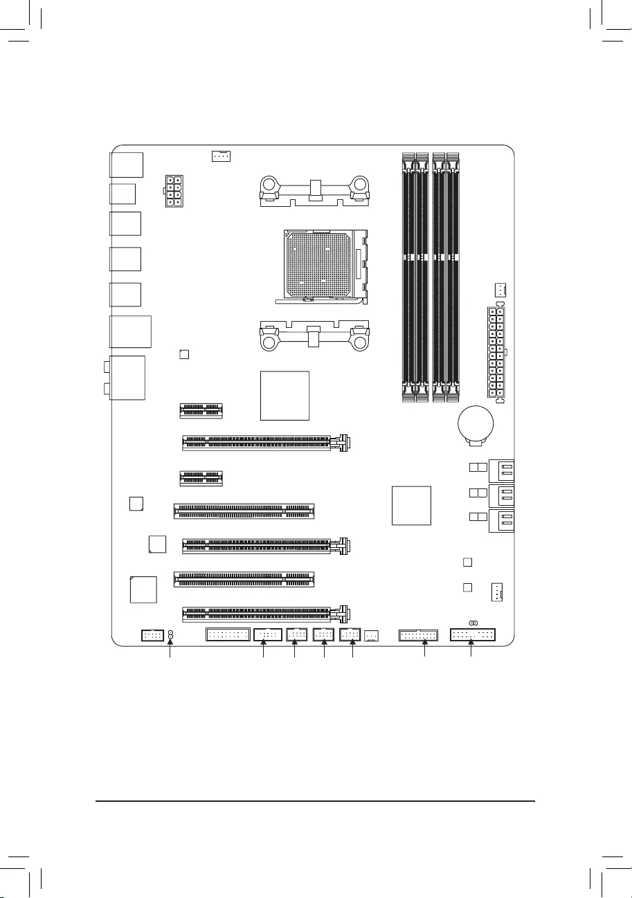
— 7 —
GA-990XA-UD3 R5 Motherboard Layout
(Note) Duetoahardwarelimitation,thePCIEX1_1slotcanonlyaccommodateashorterPCIExpressx1
expansion card. For a longer expansion card, use other expansion slots.
KB_MS_USB
CPU_FAN
ATX
GA-990XA-UD3 R5
AUDIO
SYS_FAN1
PCIEX1_1(Note)
DDR3_4
DDR3_2
ATX_12V
AMD 990X
AMD SB950
PCI1
CODEC
BAT
PCI2
F_USB2
B_BIOS
F_PANEL
M_BIOS
F_USB1
PCIEX16
R_USB1
CLR_CMOS
SPDIF_O
Socket AM3+
Realtek®
GbE LAN
iTE®
Super I/O
OPTICAL
R_USB2
R_USB30
USB_LAN
DDR3_3
DDR3_1
PWR_FAN
F_USB30
SYS_FAN2
F_USB3COMA
F_AUDIO
TPM
PCIEX1_2
PCIEX8
PCIEX4
4
5
2
3
0
1
SATA3
VIA® VL805
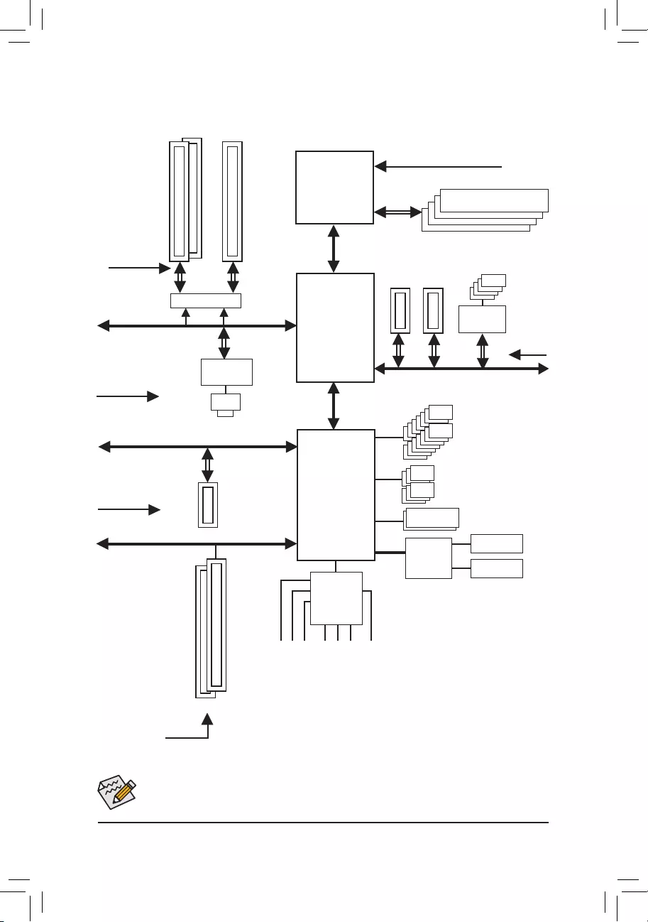
— 8 —
GA-990XA-UD3 R5 Motherboard Block Diagram
Fordetailedproductinformation/limitation(s),referto»1-2ProductSpecications.»
AM3+/AM3 CPU
Hyper Transport Bus
AMD 990X
2 PCI
PCI Bus
PCI CLK
(33MHz)
PCIe CLK
(100MHz)
PCI Express Bus
CPUCLK+/-(200MHz)
Dual BIOS
COM
LPC
Bus
1 PCI Express x4
DDR32000(O.C.)/1866/1600/1333/1066MHz
6 SATA 6Gb/s
LAN
RJ45
x4
PS/2 KB/Mouse
14 USB 2.0/1.1Ports
Realtek®
GbE LAN
x1
PCIe CLK
(100MHz)
1 PCI Express x162 PCI Express x8
Switch
or
x16 x16
PCI Express Bus
2 PCI Express x1
x1 x1
PCIe CLK
(100MHz)
Center/Subwoofer Speaker Out
Line Out
MIC
Line In
S/PDIF Out
Side Speaker Out
Rear Speaker Out
CODEC
AMD SB950
PCI Express Bus
PCIe CLK
(100MHz)
iTE®
Super I/O
Dual Channel Memory
x1
4 USB 3.0/2.0
VIA®
VL805

— 9 —
1-1 Installation Precautions
The motherboard contains numerous delicate electronic circuits and components which can become
damagedasaresultofelectrostaticdischarge(ESD).Priortoinstallation,carefullyreadtheuser’s
manual and follow these procedures:
•Prior to installation, make sure the chassis is suitable for the motherboard.
•Priorto installation, do notremoveorbreak motherboard S/N(Serial Number)stickeror
warranty sticker provided by your dealer. These stickers are required for warranty validation.
•Always remove the AC power by unplugging the power cord from the power outlet before
installing or removing the motherboard or other hardware components.
•When connecting hardware components to the internal connectors on the motherboard, make
sure they are connected tightly and securely.
•When handling the motherboard, avoid touching any metal leads or connectors.
•Itisbesttowearanelectrostaticdischarge(ESD)wriststrapwhenhandlingelectroniccom—
ponents such as a motherboard, CPU or memory. If you do not have an ESD wrist strap, keep
yourhandsdryandrsttouchametalobjecttoeliminatestaticelectricity.
•Prior to installing the motherboard, please have it on top of an antistatic pad or within an
electrostatic shielding container.
•Before unplugging the power supply cable from the motherboard, make sure the power supply
has been turned off.
•Before turning on the power, make sure the power supply voltage has been set according to
the local voltage standard.
•Before using the product, please verify that all cables and power connectors of your hardware
components are connected.
•To prevent damage to the motherboard, do not allow screws to come in contact with the
motherboard circuit or its components.
•Make sure there are no leftover screws or metal components placed on the motherboard or
within the computer casing.
•Do not place the computer system on an uneven surface.
•Do not place the computer system in a high-temperature environment.
•Turning on the computer power during the installation process can lead to damage to system
components as well as physical harm to the user.
•If you are uncertain about any installation steps or have a problem related to the use of the
product,pleaseconsultacertiedcomputertechnician.
Chapter 1 Hardware Installation
— 10 —
1-2 ProductSpecications
CPU AM3+ Socket:
— AMD AM3+ FX processors
— AMD AM3 Phenom™ II processors/ AMD Athlon™ II processors
(GotoGIGABYTE’swebsiteforthelatestCPUsupportlist.)
Hyper Transport
Bus 5200 MT/s
Chipset North Bridge: AMD 990X
South Bridge: AMD SB950
Memory 4 x DDR3 DIMM sockets supporting up to 32 GB of system memory
* DuetoaWindows32-bitoperatingsystemlimitation,whenmorethan4GBofphysical
memoryisinstalled,theactualmemorysizedisplayedwillbelessthanthesizeof
the physical memory installed.
Dual channel memory architecture
SupportforDDR32000(O.C.)/1866/1600/1333/1066MHzmemorymodules
* TosupportaDDR31866MHz(andabove)memory,youmustinstallanAM3+CPU
rst.
SupportforExtremeMemoryProle(XMP)memorymodules
(GotoGIGABYTE’swebsiteforthelatestsupportedmemoryspeedsandmemory
modules.)
Audio Realtek® ALC1150 codec
HighDenitionAudio
2/4/5.1/7.1-channel
Support for Dolby® Home Theater
Support for S/PDIF Out
LAN Realtek®GbELANchip(10/100/1000Mbit)
Expansion Slots 1xPCIExpressx16slot,runningatx16(PCIEX16)
* Foroptimumperformance,ifonlyonePCIExpressgraphicscardistobeinstalled,
be sure to install it in the PCIEX16 slot.
1xPCIExpressx16slot,runningatx8(PCIEX8)
* ThePCIEX8slotsharesbandwidthwiththePCIEX16slot.WhenthePCIEX8slotis
populated, the PCIEX16 slot will operate at up to x8 mode.
1xPCIExpressx16slot,runningatx4(PCIEX4)
2 x PCI Express x1 slots
(AllPCIExpressslotsconformtoPCIExpress2.0standard.)
2 x PCI slots
Multi-Graphics
Technology
Support for 2-Way AMD CrossFire™/NVIDIA® SLI™technology (The PCIEX16
andPCIEX8slotsonly.)
Storage Interface South Bridge:
— 6 x SATA 6Gb/s connectors
— Support for RAID 0, RAID 1, RAID 5, RAID 10, and JBOD
— 11 —
USB South Bridge:
- 14xUSB2.0/1.1ports(8portsonthebackpanel,6portsavailablethrough
theinternalUSBheaders)
VIA® VL805 chip:
- 4xUSB3.0/2.0ports(2portsonthebackpanel,2portsavailablethrough
theinternalUSBheader)
* BesuretoconnectyourUSBdevice(s)totheUSB2.0/1.1portsbeforetheUSB3.0
driverisinstalled.(Refertothelabelsinsection1-7,»BackPanelConnectors.»)
Internal
Connectors
1 x 24-pin ATX main power connector
1 x 8-pin ATX 12V power connector
6 x SATA 6Gb/s connectors
1 x CPU fan header
2 x system fan headers
1 x power fan header
1 x front panel header
1 x front panel audio header
1 x S/PDIF Out header
1 x USB 3.0/2.0 header
3 x USB 2.0/1.1 headers
1 x serial port header
1 x Clear CMOS jumper
1xTrustedPlatformModule(TPM)header
Back Panel
Connectors
1 x PS/2 keyboard/mouse port
1 x optical S/PDIF Out connector
2 x USB 3.0/2.0 ports
8 x USB 2.0/1.1 ports
1 x RJ-45 port
6xaudio jacks (Center/Subwoofer Speaker Out, Rear Speaker Out,
SideSpeakerOut,LineIn,LineOut,MicIn)
I/O Controller iTE® I/O Controller Chip
Hardware
Monitor
System voltage detection
CPU/System temperature detection
CPU/System/Power fan speed detection
CPU overheating warning
CPU/System/Power fan fail warning
CPU/System fan speed control
* Whetherthefanspeedcontrolfunctionissupportedwilldependonthecooleryou
install.
— 12 —
BIOS 2x32Mbitash
Use of licensed AMI UEFI BIOS
Support for DualBIOS™
PnP 1.0a, DMI 2.7, WfM 2.0, SM BIOS 2.7, ACPI 5.0
Unique Features Support for @BIOS
Support for Q-Flash
Support for Xpress Install
Support for EasyTune
* AvailablefunctionsinEasyTunemaydifferbymotherboardmodel.
Support for Smart Recovery 2
Support for ON/OFF Charge
Bundled
Software Norton®InternetSecurity(OEMversion)
Operating
System Support for Windows 8.1/8/7
Form Factor ATX Form Factor; 30.5cm x 24.4cm
* GIGABYTEreservestherighttomakeanychangestotheproductspecicationsandproduct-relatedinformationwithout
prior notice.
* Please visit the Support & Downloads\UtilitypageonGIGABYTE’swebsitetocheckthesupportedoperatingsystem(s)
for the software listed in the «Unique Features» and «Bundled Software» columns.
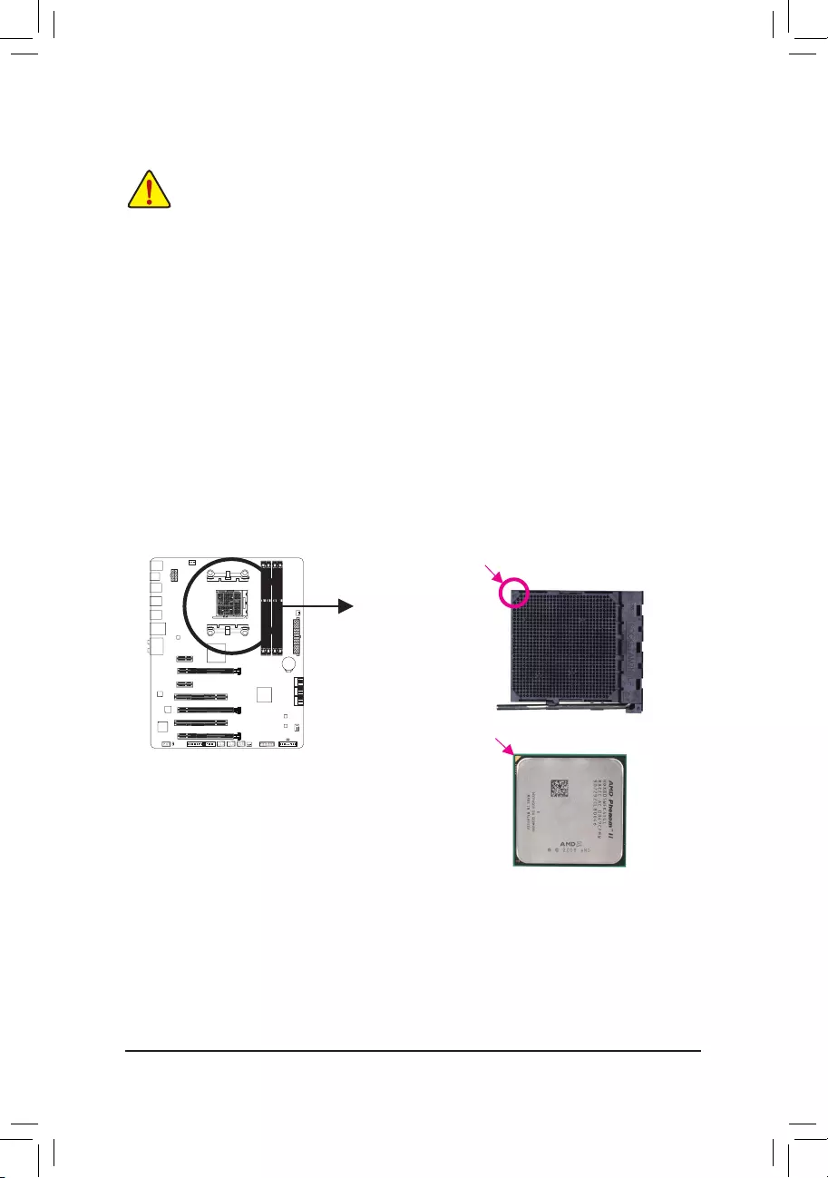
— 13 —
1-3 Installing the CPU and CPU Cooler
Read the following guidelines before you begin to install the CPU:
•Make sure that the motherboard supports the CPU.
(GotoGIGABYTE’swebsiteforthelatestCPUsupportlist.)
•Always turn off the computer and unplug the power cord from the power outlet before installing the
CPU to prevent hardware damage.
•Locate the pin one of the CPU. The CPU cannot be inserted if oriented incorrectly.
•Apply an even and thin layer of thermal grease on the surface of the CPU.
•Do not turn on the computer if the CPU cooler is not installed, otherwise overheating and damage
of the CPU may occur.
•SettheCPUhostfrequencyinaccordancewiththeCPUspecications.Itisnotrecommended
thatthesystembusfrequencybesetbeyondhardwarespecicationssinceitdoesnotmeetthe
standard requirements for the peripherals. If you wish to set the frequency beyond the standard
specications,pleasedosoaccordingtoyourhardwarespecicationsincludingtheCPU,graphics
card, memory, hard drive, etc.
1-3-1 Installing the CPU
A. Locate the alignment keys on the motherboard CPU socket and the notches on the CPU.
AM3+/AM3 CPU
A Small Triangle Marking
Denotes CPU Pin One
AM3+ Socket
A Small Triangle Mark
Denotes Pin One of
the Socket
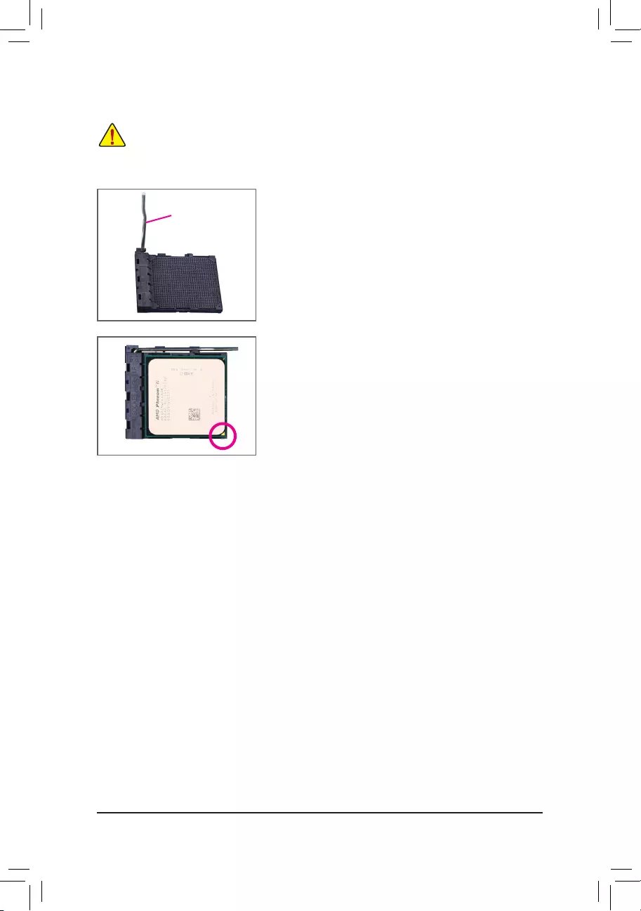
— 14 —
B. Follow the steps below to correctly install the CPU into the motherboard CPU socket.
•Before installing the CPU, make sure to turn off the computer and unplug the power cord from the
power outlet to prevent damage to the CPU.
•DonotforcetheCPUintotheCPUsocket.TheCPUcannottiniforientedincorrectly.Adjustthe
CPU orientation if this occurs.
Step 1:
Completely lift up the CPU socket locking lever.
Step 2:
AligntheCPUpinone(smalltrianglemarking)withthetrianglemark
on the CPU socket and gently insert the CPU into the socket. Make
surethattheCPUpinstperfectlyintotheirholes.
OncetheCPUispositionedintoitssocket,placeonengerdownon
the middle of the CPU, lowering the locking lever and latching it into
the fully locked position.
CPU Socket
Locking Lever
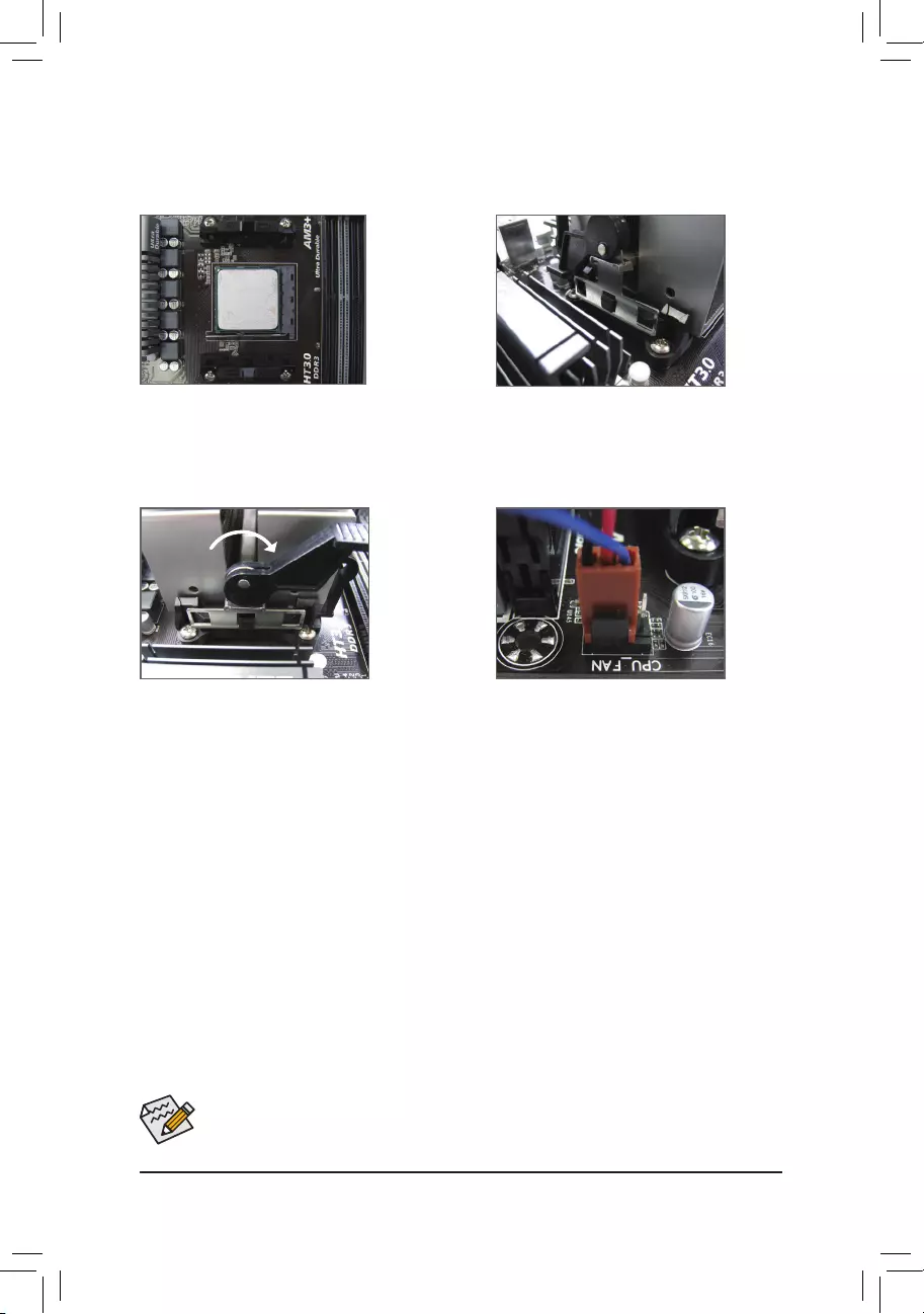
— 15 —
Use extreme care when removing the CPU cooler because the thermal grease/tape between the CPU
cooler and CPU may adhere to the CPU. Inadequately removing the CPU cooler may damage the CPU.
1-3-2 Installing the CPU Cooler
FollowthestepsbelowtocorrectlyinstalltheCPUcooleronthemotherboard.(Thefollowingprocedureuses
theGIGABYTEcoolerastheexample.)
Step 1:
Apply an even and thin layer of thermal grease on
the surface of the installed CPU.
Step 2:
Hook the CPU cooler clip to the mounting lug on
one side of the retention frame. On the other side,
push straight down on the CPU cooler clip to hook
it to the mounting lug on the retention frame.
Step 3:
Turn the cam handle from the left side to the
rightside(as the picture above shows)tolock
intoplace.(RefertoyourCPUcoolerinstallation
manualforinstructionsoninstallingthecooler.)
Step 4:
Finally, attach the power connector of the CPU
coolertotheCPUfanheader(CPU_FAN)onthe
motherboard.
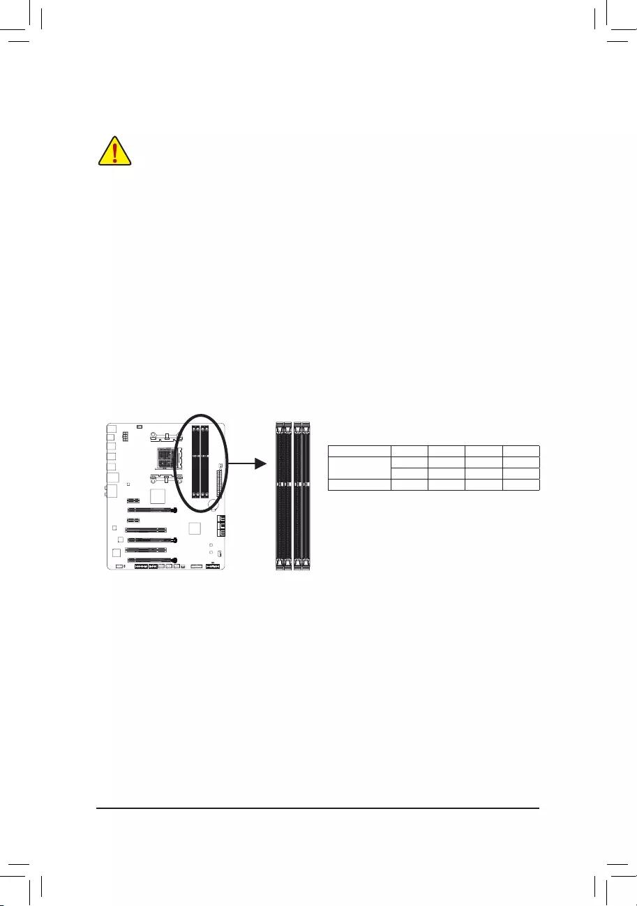
— 16 —
1-4 Installing the Memory
Read the following guidelines before you begin to install the memory:
•Make sure that the motherboard supports the memory. It is recommended that memory of the same
capacity, brand, speed, and chips be used.
(GotoGIGABYTE’swebsiteforthelatestsupportedmemoryspeedsandmemorymodules.)
•Always turn off the computer and unplug the power cord from the power outlet before installing the
memory to prevent hardware damage.
•Memory modules have a foolproof design. A memory module can be installed in only one direction.
If you are unable to insert the memory, switch the direction.
1-4—1 DualChannelMemoryConguration
This motherboard provides four DDR3 memory sockets and supports Dual Channel Technology. After the
memoryisinstalled,theBIOSwillautomaticallydetectthespecicationsandcapacityofthememory.Enabling
Dual Channel memory mode will double the original memory bandwidth.
The four DDR3 memory sockets are divided into two channels and each channel has two memory sockets as
following:
ChannelA:DDR3_2,DDR3_4
ChannelB:DDR3_1,DDR3_3
Due to CPU limitations, read the following guidelines before installing the memory in Dual Channel mode.
1. Dual Channel mode cannot be enabled if only one DDR3 memory module is installed.
2. When enabling Dual Channel mode with two or four memory modules, it is recommended that memory
of the same capacity, brand, speed, and chips be used and installed in the same colored DDR3
sockets for optimum performance. when enabling Dual Channel mode with two memory modules, we
recommend that you installthemintheDDR3_1andDDR3_2sockets.
DualChannelMemoryCongurationsTable
DDR3_4 DDR3_2 DDR3_3 DDR3_1
Two Modules — — DS/SS — — DS/SS
DS/SS — — DS/SS — —
Four Modules DS/SS DS/SS DS/SS DS/SS
(SS=Single-Sided,DS=Double-Sided,»--«=NoMemory)
DDR3_4
DDR3_2
DDR3_3
DDR3_1
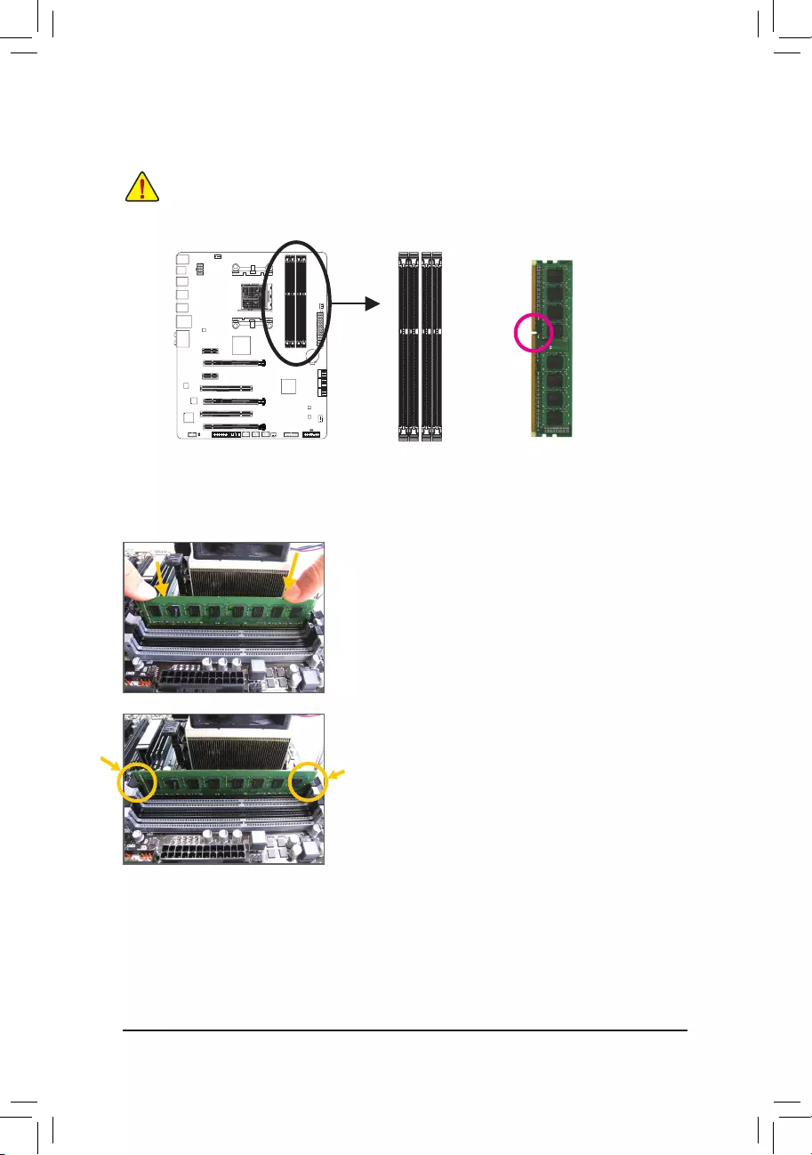
— 17 —
1-4-2 Installing a Memory
Before installing a memory module, make sure to turn off the computer and unplug the power
cord from the power outlet to prevent damage to the memory module. DDR3 and DDR2 DIMMs are
not compatible to each other or DDR DIMMs. Be sure to install DDR3 DIMMs on this motherboard.
ADDR3memorymodulehasanotch,soitcanonlytinonedirection.Followthestepsbelowtocorrectlyinstall
your memory modules in the memory sockets.
Step 1:
Note the orientation of the memory module. Spread the retaining clips
at both ends of the memory socket. Place the memory module on the
socket.Asindicatedinthepictureontheleft,placeyourngerson
the top edge of the memory, push down on the memory and insert it
vertically into the memory socket.
Step 2:
The clips at both ends of the socket will snap into place when the
memory module is securely inserted.
Notch
DDR3 DIMM
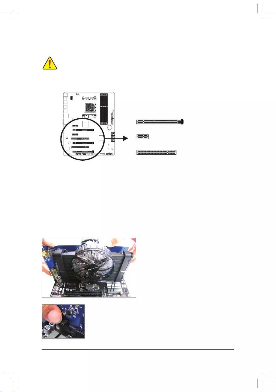
— 18 —
1-5 Installing an Expansion Card
Read the following guidelines before you begin to install an expansion card:
•Make sure the motherboard supports the expansion card. Carefully read the manual that came
with your expansion card.
•Always turn off the computer and unplug the power cord from the power outlet before installing an
expansion card to prevent hardware damage.
PCI Slot
Follow the steps below to correctly install your expansion card in the expansion slot.
1. Locate an expansion slot that supports your card. Remove the metal slot cover from the chassis back panel.
2. Align the card with the slot, and press down on the card until it is fully seated in the slot.
3. Make sure the metal contacts on the card are completely inserted into the slot.
4. Secure the card’s metal bracket to the chassis back panel with a screw.
5. Afterinstallingallexpansioncards,replacethechassiscover(s).
6. Turn on your computer. If necessary, go to BIOS Setup to make any required BIOS changes for your
expansioncard(s).
7. Install the driver provided with the expansion card in your operating system.
Example: Installing and Removing a PCI Express Graphics Card:
PCI Express x1 Slot
PCI Express x16 Slot
•Installing a Graphics Card:
Gently push down on the top edge of the card until
it is fully inserted into the PCI Express slot. Make
sure the card is securely seated in the slot and
does not rock.
•Removing the Card:
Gently push back on the lever on the slot and then lift the card straight out from
the slot.
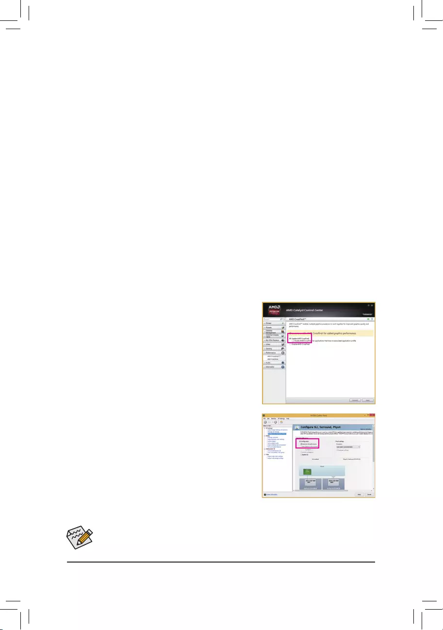
— 19 —
1-6 Setting up AMD CrossFire™/NVIDIA® SLI™Conguration
C-2. To Enable SLI Function
After installing the graphics card driver in the operating system, go to
the NVIDIA Control Panel. Browse to the CongureSLI,Surround,
Physx screen and ensure Maximize 3D performance is enabled.
A. System Requirements
—Windows 8.1/8/7 operating system
—A CrossFire/SLI-supported motherboard with two PCI Express x16 slots and correct driver
—Two CrossFire/SLI-ready graphics cards of identical brand and chip and correct driver
—CrossFire(Note)/SLI bridge connectors
—Apowersupplywithsufcientpowerisrecommended(Refertothemanualofyourgraphicscardsforthe
powerrequirement)
B. Connecting the Graphics Cards
Step 1:
Observe the steps in «1-5 Installing an Expansion Card» and install two CrossFire/SLI graphics cards on the
PCIEX16 and PCIEX8 slots.
Step 2:
Insert the CrossFire(Note)/SLI bridge connectors in the CrossFire/SLI gold edge connectors on top of the cards.
Step 3:
Plug the display cable into the graphics card on the PCIEX16 slot.
C.ConguringtheGraphicsCardDriver
C-1. To Enable CrossFire Function
After installing the graphics card driver in the operating system, go
to the AMD Catalyst Control Center. Browse to Performance\
AMD CrossFireX™ and ensure the Enable AMD CrossFireX
check box is selected. If your system has more than two CrossFire
cards, select the GPU combination you want to use and click Ap-
ply.(Availablecombinationoptionsaredependentonthenumber
ofgraphicscards.)
(Note) Thebridgeconnector(s)maybeneededornotdependingonyourgraphicscards.
Procedure and driver screen for enabling CrossFire/SLI technology may differ by graphics cards and
driver version. Refer to the manual that came with your graphics cards for more information about
enabling CrossFire/SLI technology.
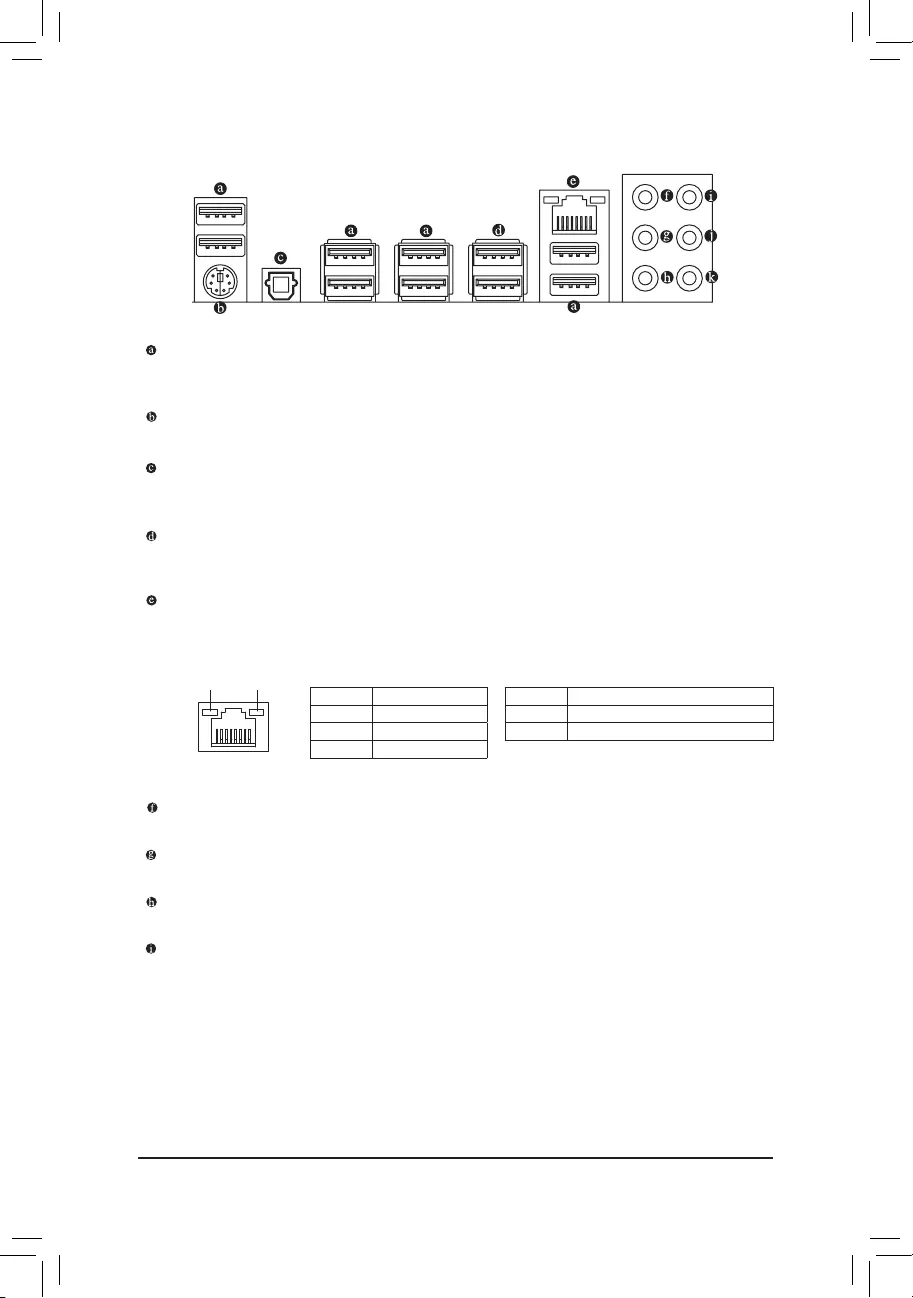
— 20 —
1-7 Back Panel Connectors
USB 2.0/1.1 Port
TheUSB port supportstheUSB 2.0/1.1specication.Use this portforUSB devices suchas a USB
keyboard/mouse,USBprinter,USBashdriveandetc.
PS/2 Keyboard/Mouse Port
Use this port to connect a PS/2 mouse or keyboard.
Optical S/PDIF Out Connector
This connector provides digital audio out to an external audio system that supports digital optical audio.
Before using this feature, ensure that your audio system provides an optical digital audio in connector.
USB 3.0/2.0 Port
TheUSB3.0portsupportstheUSB3.0specicationandiscompatibletotheUSB2.0/1.1specication.
UsethisportforUSBdevicessuchasaUSBkeyboard/mouse,USBprinter,USBashdriveandetc.
RJ-45 LAN Port
The Gigabit Ethernet LAN port provides Internet connection at up to 1 Gbps data rate. The following
describes the states of the LAN port LEDs.
Activity LED
Connection/
Speed LED
LAN Port
Connection/Speed LED:
State Description
Orange 1 Gbps data rate
Green 100 Mbps data rate
Off 10 Mbps data rate
Activity LED:
State Description
Blinking Data transmission or receiving is occurring
Off No data transmission or receiving is occurring
Center/Subwoofer Speaker Out Jack (Orange)
Usethisaudiojacktoconnectcenter/subwooferspeakersina5.1/7.1-channelaudioconguration.
Rear Speaker Out Jack (Black)
Thisjackcanbeusedtoconnectfrontspeakersina7.1-channelaudioconguration.
Side Speaker Out Jack (Gray)
Usethisaudiojacktoconnectsidespeakersina4/5.1/7.1-channelaudioconguration.
Line In Jack (Blue)
The line in jack. Use this audio jack for line in devices such as an optical drive, walkman, etc.
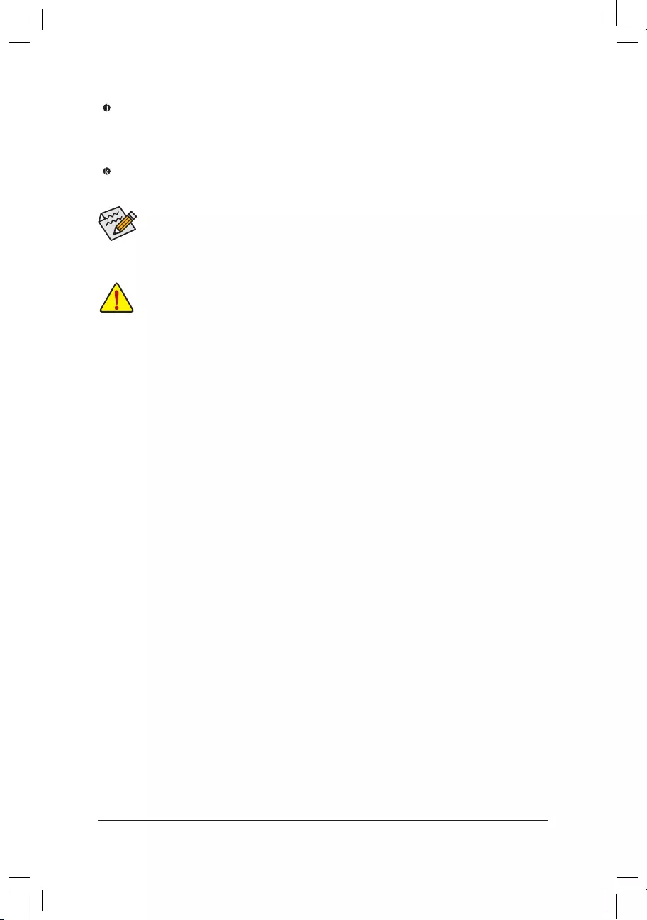
— 21 —
Theaudiojackscanbereconguredtoperformdifferentfunctionsviatheaudiosoftware(supported
functionsforeachjackmayvarybasedonhardwarespecication).OnlymicrophonesstillMUSTbe
connected to the default Mic in jack. Refer to the instructions on setting up a 2/4/5.1/7.1-channel audio
congurationinChapter6,»Conguring2/4/5.1/7.1-ChannelAudio.»
•Whenremovingthecableconnectedtoabackpanelconnector,rstremovethecablefromyour
device and then remove it from the motherboard.
•When removing the cable, pull it straight out from the connector. Do not rock it side to side to prevent
an electrical short inside the cable connector.
Line Out Jack (Green)
The line out jack. This jack supports audio amplifying function. For better sound quality, it is recommended
that you connect your headphone/speaker to this jack. Use this audio jack for a headphone or 2-channel
speaker.Thisjackcanbeusedtoconnectfrontspeakersina4/5.1/7.1-channelaudioconguration.
Mic In Jack (Pink)
The Mic in jack. Microphones must be connected to this jack.
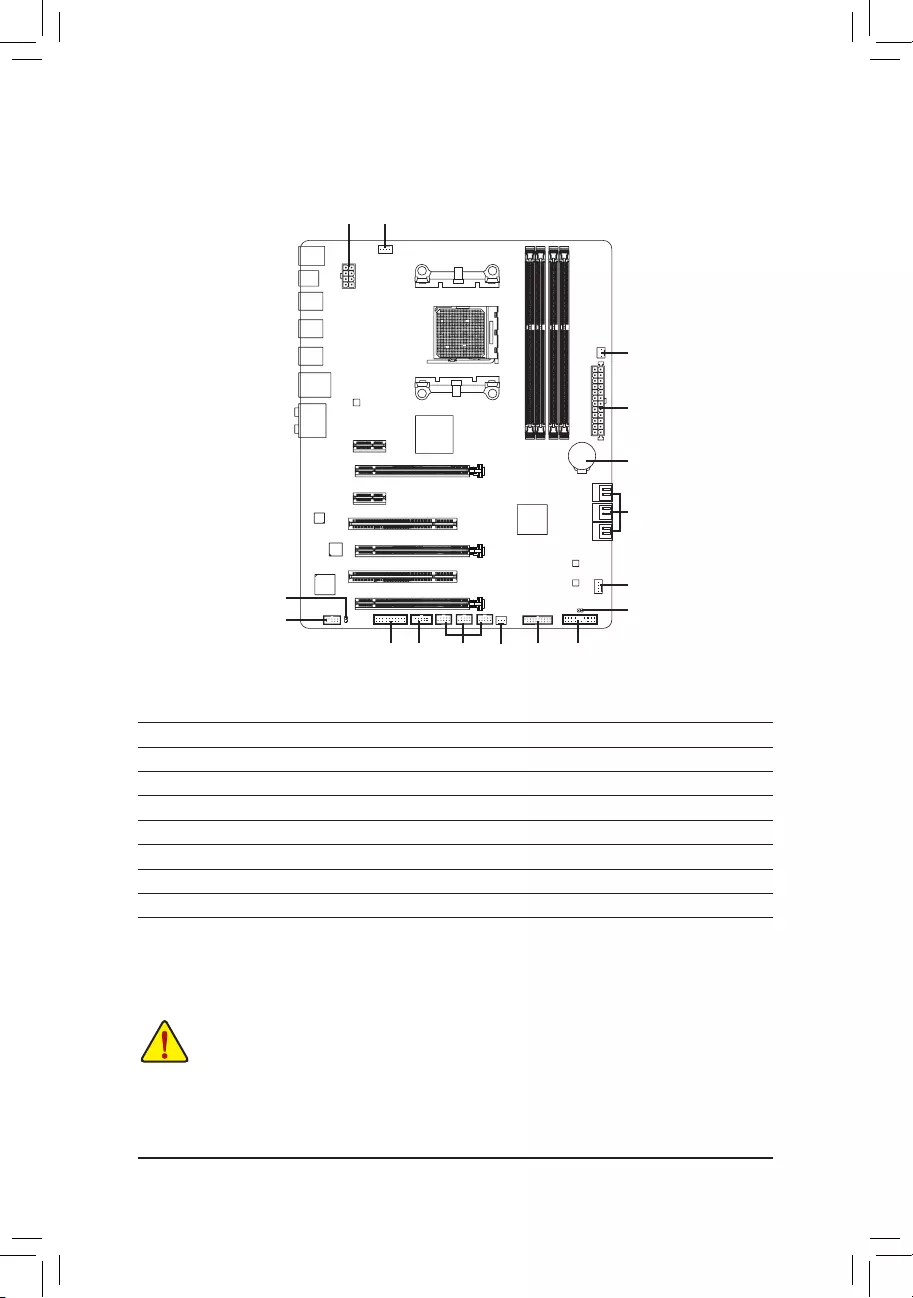
— 22 —
1-8 Internal Connectors
Read the following guidelines before connecting external devices:
•First make sure your devices are compliant with the connectors you wish to connect.
•Before installing the devices, be sure to turn off the devices and your computer. Unplug the power
cord from the power outlet to prevent damage to the devices.
•After installing the device and before turning on the computer, make sure the device cable has
been securely attached to the connector on the motherboard.
1) ATX_12V
2) ATX
3) CPU_FAN
4) SYS_FAN1/2
5) PWR_FAN
6) SATA3 0/1/2/3/4/5
7) F_PANEL
F_AUDIO
9) SPDIF_O
10) F_USB30
11) F_USB1/F_USB2/F_USB3
12) COMA
13) TPM
14) BAT
15) CLR_CMOS
1 3
8
13 11 4
4
6
14
2
5
71012
915
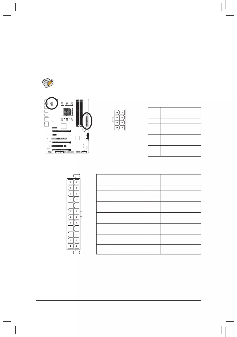
— 23 —
1/2) ATX_12V/ATX (2×4 12V Power Connector and 2×12 Main Power Connector)
With the use of the power connector, the power supply can supply enough stable power to all the components
onthemotherboard.Beforeconnectingthepowerconnector,rstmakesurethepowersupplyisturned
off and all devices are properly installed. The power connector possesses a foolproof design. Connect the
power supply cable to the power connector in the correct orientation.
The 12V power connector mainly supplies power to the CPU. If the 12V power connector is not connected,
the computer will not start.
To meet expansion requirements, it is recommended that a power supply that can withstand high
powerconsumptionbeused(500Worgreater).Ifapowersupplyisusedthatdoesnotprovidethe
required power, the result can lead to an unstable or unbootable system.
131
2412
ATX
ATX_12V
5
8
1
4
ATX_12V:
Pin No. Denition
1GND(Onlyfor2×4-pin12V)
2GND(Onlyfor2×4-pin12V)
3 GND
4 GND
5+12V(Onlyfor2×4-pin12V)
6+12V(Onlyfor2×4-pin12V)
7 +12V
8 +12V
ATX:
Pin No. Denition Pin No. Denition
1 3.3V 13 3.3V
2 3.3V 14 -12V
3 GND 15 GND
4 +5V 16 PS_ON(softOn/Off)
5 GND 17 GND
6 +5V 18 GND
7 GND 19 GND
8 Power Good 20 -5V
95VSB(standby+5V) 21 +5V
10 +12V 22 +5V
11 +12V(Only for 2×12-pin
ATX)
23 +5V(Onlyfor2×12-pinATX)
12 3.3V(Only for2×12-pin
ATX)
24 GND(Onlyfor2×12-pinATX)
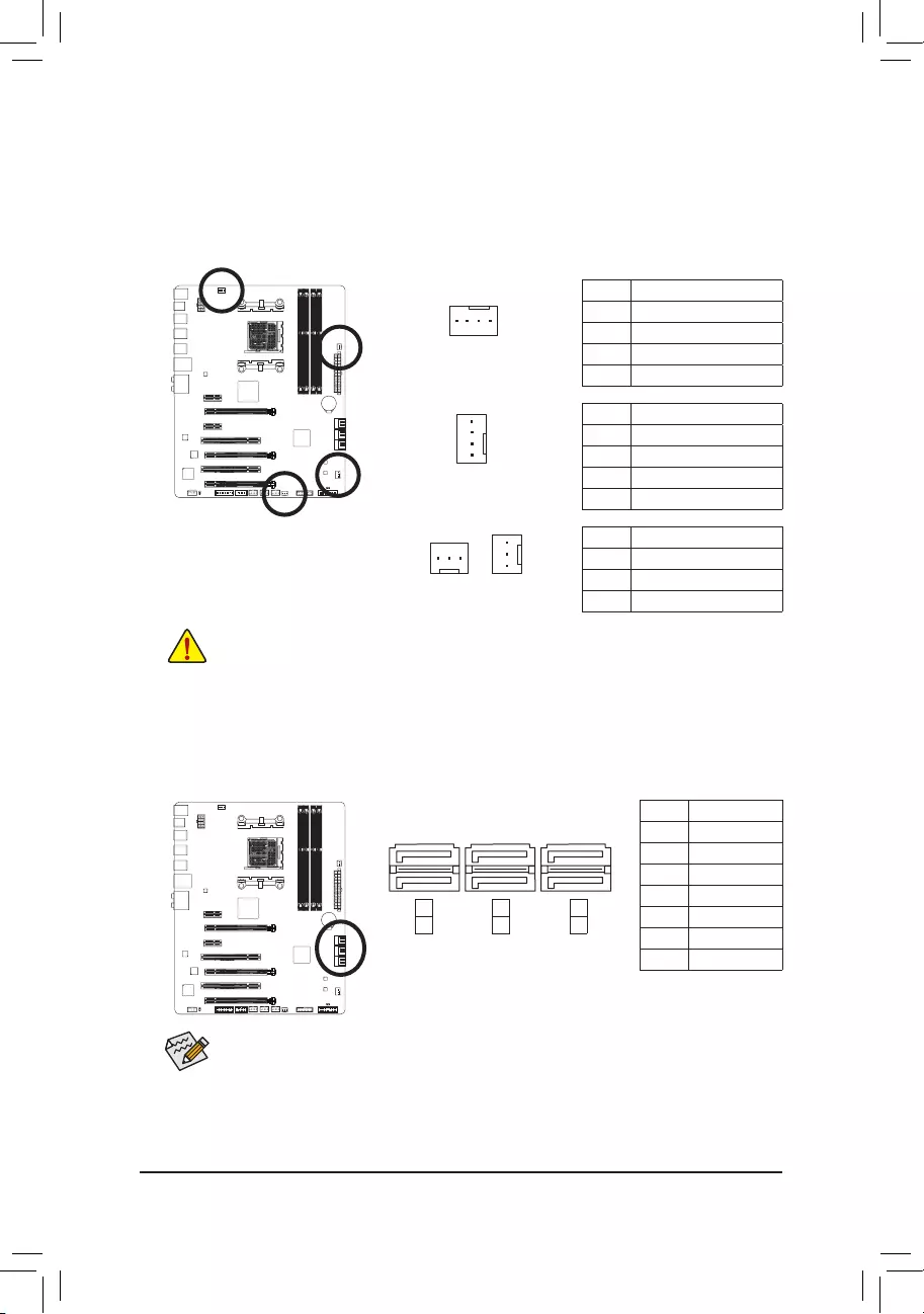
— 24 —
•Be sure to connect fan cables to the fan headers to prevent your CPU and system from overheat—
ing. Overheating may result in damage to the CPU or the system may hang.
•Thesefanheadersarenotcongurationjumperblocks.Donotplaceajumpercapontheheaders.
3/4/5) CPU_FAN/SYS_FAN1/SYS_FAN2/PWR_FAN (Fan Headers)
Themotherboardhasa4-pinCPUfanheader(CPU_FAN),a4-pin(SYS_FAN1)andtwo3-pin(SYS_FAN2/
PWR_FAN)systemfanheaders.Mostfanheaderspossessafoolproofinsertiondesign.Whenconnecting
afancable,besuretoconnectitinthecorrectorientation(theblackconnectorwireisthegroundwire).
The speed control function requires the use of a fan with fan speed control design. For optimum heat dis-
sipation, it is recommended that a system fan be installed inside the chassis.
1
CPU_FAN
SYS_FAN1
SYS_FAN2
1
1
1
PWR_FAN
CPU_FAN:
SYS_FAN1:
SYS_FAN2/PWR_FAN:
Pin No. Denition
1 GND
2 +12V /Speed Control
3 Sense
4 Speed Control
Pin No. Denition
1 GND
2 +12V /Speed Control
3 Sense
4 Reserve
Pin No. Denition
1 GND
2 +12V
3 Sense
6) SATA3 0/1/2/3/4/5 (SATA 6Gb/s Connectors)
The SATA connectors conform to SATA 6Gb/s standard and are compatible with SATA 3Gb/s and SATA
1.5Gb/s standard. Each SATA connector supports a single SATA device. The AMD South Bridge supports
RAID0,RAID1,RAID5,RAID10,andJBOD.RefertoChapter5,»ConguringSATAHardDrive(s),»for
instructionsonconguringaRAIDarray.
To enable hot-plugging for the SATA ports, refer to Chapter 2, «BIOS Setup,» «Peripherals\SB SATA
Conguration,»formoreinformation.
Pin No. Denition
1 GND
2 TXP
3 TXN
4 GND
5 RXN
6 RXP
7 GND
1
1
7
7
0
1
2
3
4
5
SATA3
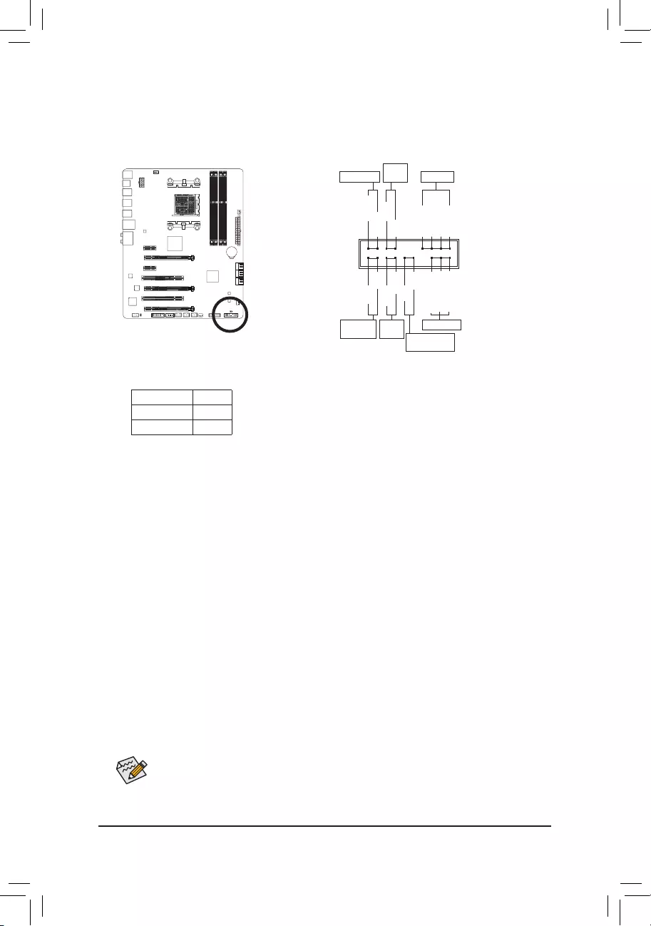
— 25 —
The front panel design may differ by chassis. A front panel module mainly consists of power switch,
reset switch, power LED, hard drive activity LED, speaker and etc. When connecting your chassis
front panel module to this header, make sure the wire assignments and the pin assignments are
matched correctly.
7) F_PANEL (Front Panel Header)
Connect the power switch, reset switch, speaker, chassis intrusion switch/sensor and system status indicator
on the chassis to this header according to the pin assignments below. Note the positive and negative pins
before connecting the cables.
•PW (PowerSwitch,Red):
Connectstothepowerswitchonthechassisfrontpanel.Youmaycongurethewaytoturnoffyour
systemusingthe power switch (refertoChapter 2, «BIOS Setup,»«PowerManagement,» for more
information).
•SPEAK (Speaker,Orange):
Connects to the speaker on the chassis front panel. The system reports system startup status by issuing
a beep code. One single short beep will be heard if no problem is detected at system startup.
•HD (HardDriveActivityLED,Blue):
Connects to the hard drive activity LED on the chassis front panel. The LED is on when the hard drive
is reading or writing data.
•RES (ResetSwitch,Green):
Connects to the reset switch on the chassis front panel. Press the reset switch to restart the computer
ifthecomputerfreezesandfailstoperformanormalrestart.
•CI (ChassisIntrusionHeader,Gray):
Connects to the chassis intrusion switch/sensor on the chassis that can detect if the chassis cover has
been removed. This function requires a chassis with a chassis intrusion switch/sensor.
•NC (Orange):
No connection.
•PLED/PWR_LED (PowerLED,Yellow/Purple):
Connects to the power status indicator on the chassis front panel. The LED
is on when the system is operating. The LED is off when the system is in S3/
S4sleepstateorpoweredoff(S5).
System Status LED
S0 On
S3/S4/S5 Off
Power LED
1
2
19
20
CI-
CI+
PWR_LED-
PWR_LED+
PLED-
PW-
SPEAK+
SPEAK-
PLED+
PW+
Power LED
HD-
RES+
HD+
RES-
Hard Drive
Activity LED
Reset
Switch Chassis Intrusion
Header
Power
Switch Speaker
PWR_LED-
NC
NC
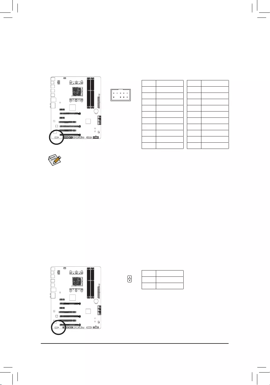
— 26 —
•The front panel audio header supports HD audio by default. If your chassis provides an AC’97
front panel audio module, refer to the instructions on how to activate AC’97 functionality via the
audiosoftwareinChapter6,»Conguring2/4/5.1/7.1-ChannelAudio.»
•Audio signals will be present on both of the front and back panel audio connections simultane-
ously.Ifyouwanttomutethebackpanelaudio(onlysupportedwhenusinganHDfrontpanel
audiomodule),refertoChapter6,»Conguring2/4/5.1/7.1-ChannelAudio.»
•Some chassis provide a front panel audio module that has separated connectors on each wire
instead of a single plug. For information about connecting the front panel audio module that has
different wire assignments, please contact the chassis manufacturer.
9) SPDIF_O (S/PDIF Out Header)
ThisheadersupportsdigitalS/PDIFOutandconnectsaS/PDIFdigitalaudiocable(providedbyexpansion
cards)fordigitalaudiooutputfromyourmotherboardtocertainexpansioncardslikegraphicscardsand
sound cards. For example, some graphics cards may require you to use a S/PDIF digital audio cable for
digital audio output from your motherboard to your graphics card if you wish to connect an HDMI display
to the graphics card and have digital audio output from the HDMI display at the same time.
For information about connecting the S/PDIF digital audio cable, carefully read the manual for your expan-
sion card.
For HD Front Panel Audio: For AC’97 Front Panel Audio:
Pin No. Denition
1MIC2_L
2 GND
3MIC2_R
4-ACZ_DET
5LINE2_R
6 Sense
7FAUDIO_JD
8 No Pin
9LINE2_L
10 Sense
Pin No. Denition
1 MIC
2 GND
3 MIC Power
4 NC
5LineOut(R)
6 NC
7 NC
8 No Pin
9LineOut(L)
10 NC
Pin No. Denition
1 SPDIFO
2 GND
1
F_AUDIO (Front Panel Audio Header)
ThefrontpanelaudioheadersupportsIntelHighDenitionaudio(HD)andAC’97audio.Youmayconnect
your chassis front panel audio module to this header. Make sure the wire assignments of the module
connector match the pin assignments of the motherboard header. Incorrect connection between the module
connector and the motherboard header will make the device unable to work or even damage it.
F_USB30 F_U
B_
F_ F_
_
B
BS_
B
SB_
B
_S
S_
_
B
_U
_
B
S
123
123
123
123
1
1
1
1
BSS
S
_S
SSU
1 2 3
S3 BSSS U
__ 3
F_USB3F
S _
S _
S _
SF
B_
F
_0
S
S
_0F
_F
9 1
10 2
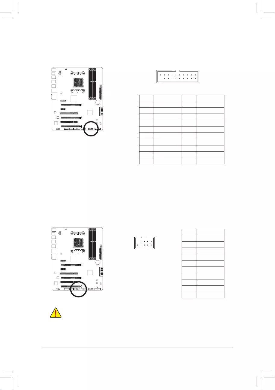
— 27 —
11) F_USB1/F_USB2/F_USB3 (USB 2.0/1.1 Headers)
TheheadersconformtoUSB2.0/1.1specication.EachUSBheadercanprovidetwoUSBportsviaan
optional USB bracket. For purchasing the optional USB bracket, please contact the local dealer.
•DonotplugtheIEEE1394bracket(2×5-pin)cableintotheUSB2.0/1.1header.
•Prior to installing the USB bracket, be sure to turn off your computer and unplug the power cord
from the power outlet to prevent damage to the USB bracket.
10
9
2
1
Pin No. Denition
1Power(5V)
2Power(5V)
3 USB DX-
4 USB DY—
5 USB DX+
6 USB DY+
7 GND
8 GND
9 No Pin
10 NC
10) F_USB30 (USB 3.0/2.0 Header)
TheheaderconformstoUSB3.0/2.0specicationandcanprovidetwoUSBports.Forpurchasingthe
optional 3.5″ front panel that provides two USB 3.0/2.0 ports, please contact the local dealer.
Pin No. Denition Pin No. Denition
1 VBUS 11 D2+
2 SSRX1- 12 D2-
3 SSRX1+ 13 GND
4 GND 14 SSTX2+
5 SSTX1- 15 SSTX2-
6 SSTX1+ 16 GND
7 GND 17 SSRX2+
8 D1- 18 SSRX2-
9 D1+ 19 VBUS
10 NC 20 No Pin
F_USB30 F_U
B_
F_ F_
_
B
BS_
B
SB_
B
_S
S_
_
B
_U
_
B
S
123
123
123
123
1
1
1
1
BSS
S
_S
SSU
1 2 3
S3 BSSS U
__ 3
F_USB3F
S _
S _
S _
SF
B_
F
_0
S
S
_0F
_F
10
11
20
1
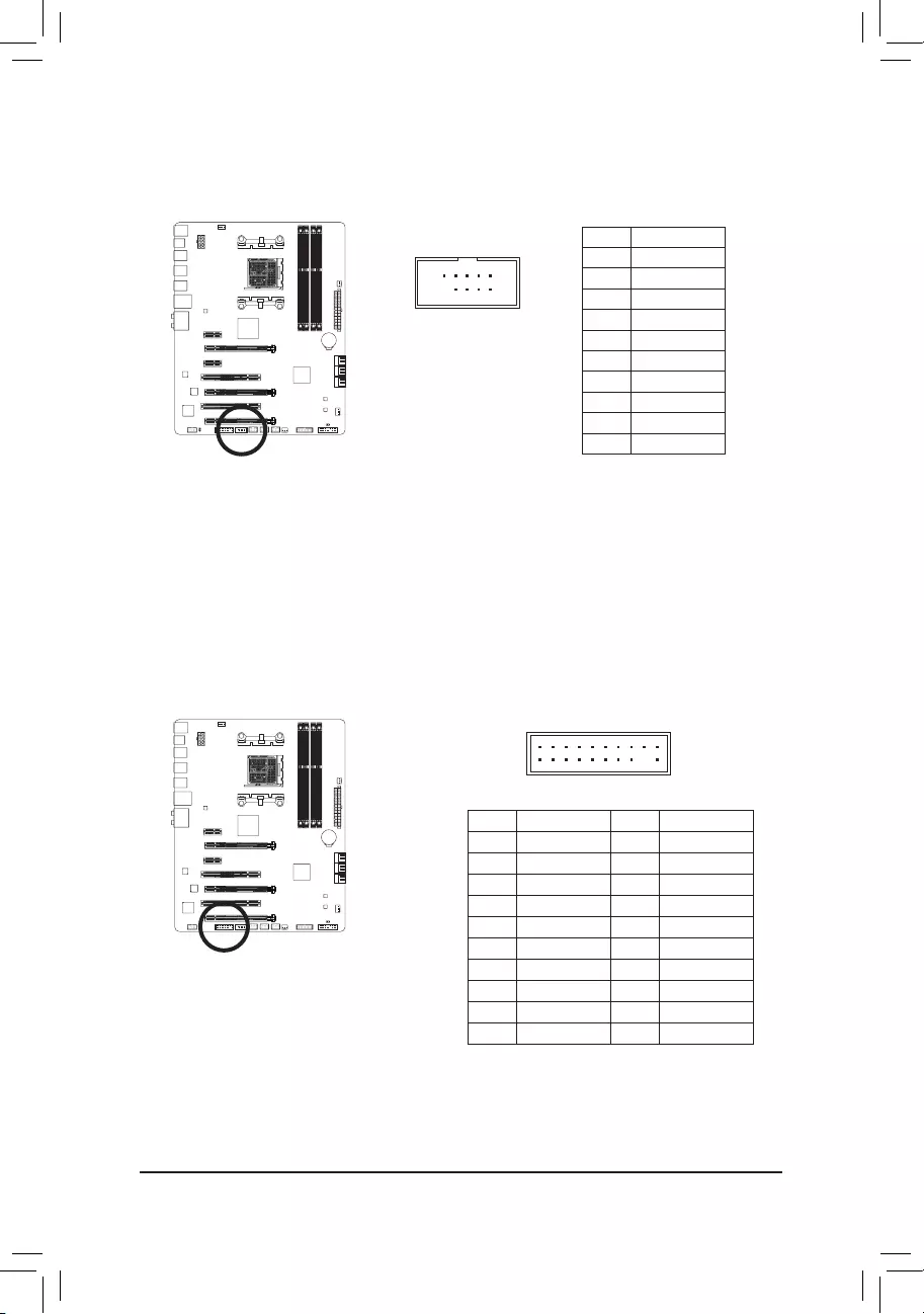
— 28 —
12) COMA (Serial Port Header)
The COM header can provide one serial port via an optional COM port cable. For purchasing the optional
COM port cable, please contact the local dealer.
10
9
2
1
Pin No. Denition
1 NDCD-
2 NSIN
3 NSOUT
4 NDTR-
5 GND
6NDSR-
7 NRTS-
8 NCTS-
9 NRI-
10 No Pin
20
19
2
1
F_USB30 F_U
B_
F_ F_
_
B
BS_
B
SB_
B
_S
S_
_
B
_U
_
B
S
123
123
123
123
1
1
1
1
BSS
S
_S
SSU
1 2 3
S3 BSSS U
__ 3
F_USB3F
S _
S _
S _
SF
B_
F
_0
S
S
_0F
_F
13) TPM (Trusted Platform Module Header)
YoumayconnectaTPM(TrustedPlatformModule)tothisheader.
Pin No. Denition Pin No. Denition
1 LCLK 11 LAD0
2 GND 12 GND
3 LFRAME 13 NC
4 No Pin 14 ID
5 LRESET 15 SB3V
6 NC 16 SERIRQ
7 LAD3 17 GND
8 LAD2 18 NC
9 VCC3 19 NC
10 LAD1 20 SUSCLK
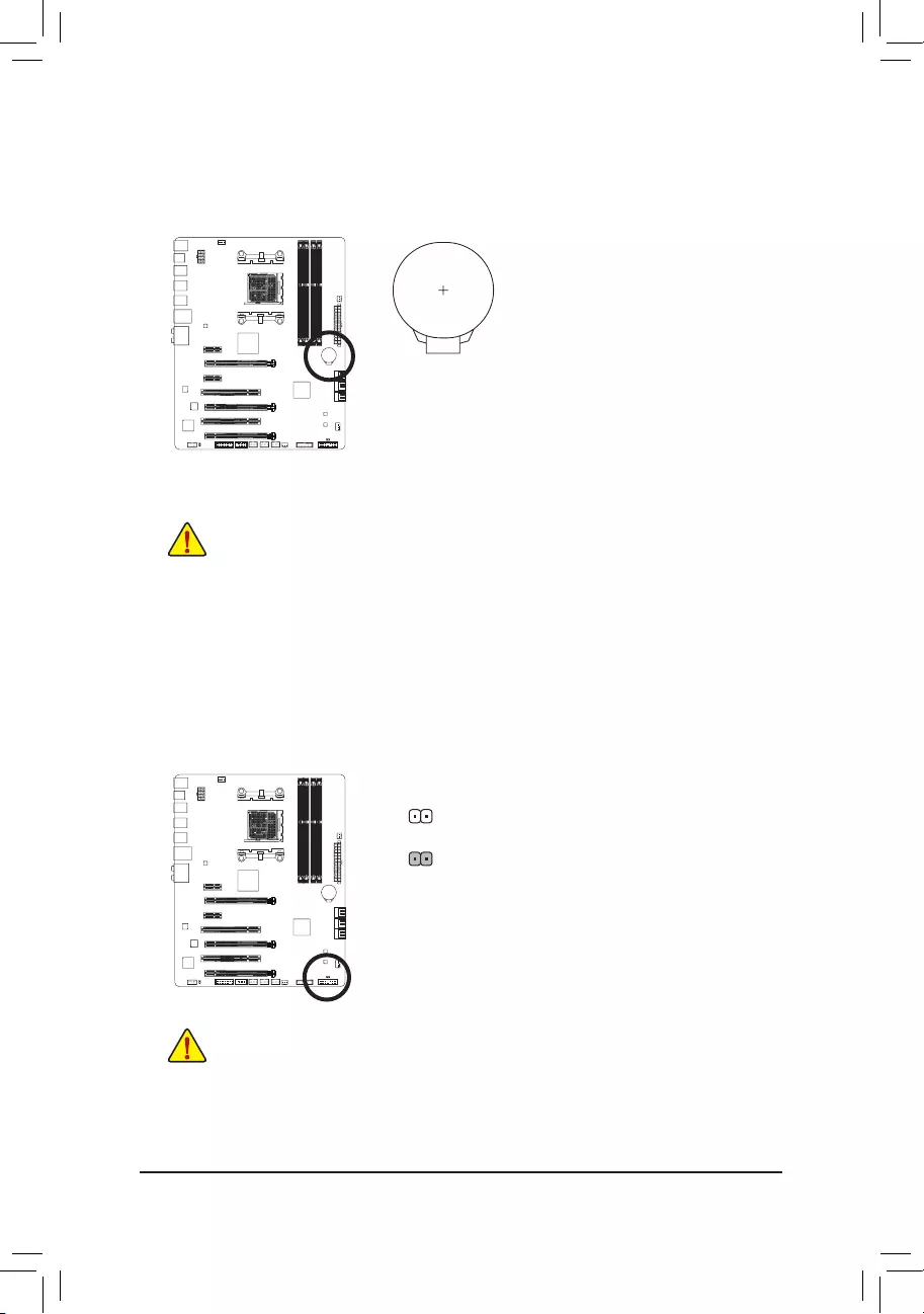
— 29 —
14) BAT (Battery)
Thebatteryprovidespowertokeepthevalues(suchasBIOScongurations,date,andtimeinformation)
in the CMOS when the computer is turned off. Replace the battery when the battery voltage drops to a low
level, or the CMOS values may not be accurate or may be lost.
You may clear the CMOS values by removing the battery:
1. Turn off your computer and unplug the power cord.
2. Gently remove the battery from the battery holder and wait for one minute.
(Oruseametalobjectlikeascrewdrivertotouchthepositiveandnegative
terminalsofthebatteryholder,makingthemshortfor5seconds.)
3. Replace the battery.
4. Plug in the power cord and restart your computer.
•Always turn off your computer and unplug the power cord before replacing the battery.
•Replace the battery with an equivalent one. Danger of explosion if the battery is replaced with
an incorrect model.
•Contact the place of purchase or local dealer if you are not able to replace the battery by yourself
or uncertain about the battery model.
•Wheninstallingthebattery,notetheorientationofthepositiveside(+)andthenegativeside(-)
ofthebattery(thepositivesideshouldfaceup).
•Used batteries must be handled in accordance with local environmental regulations.
15) CLR_CMOS (Clear CMOS Jumper)
UsethisjumpertocleartheBIOScongurationandresettheCMOSvaluestofactorydefaults.Toclear
the CMOS values, use a metal object like a screwdriver to touch the two pins for a few seconds.
•Always turn off your computer and unplug the power cord from the power outlet before clearing
the CMOS values.
•Aftersystemrestart,gotoBIOSSetuptoloadfactorydefaults(selectLoadOptimizedDefaults)or
manuallyconguretheBIOSsettings(refertoChapter2,«BIOSSetup,»forBIOScongurations).
Open: Normal
Short: Clear CMOS Values

— 30 —
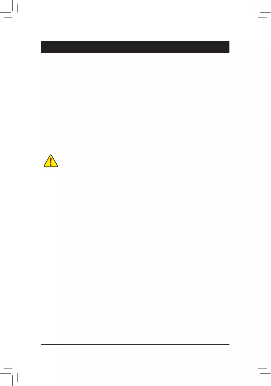
— 31 —
BIOS(BasicInputand Output System) records hardware parameters of thesysteminthe CMOS on the
motherboard.ItsmajorfunctionsincludeconductingthePower-OnSelf-Test(POST)duringsystemstartup,
saving system parameters and loading operating system, etc. BIOS includes a BIOS Setup program that allows
theusertomodifybasicsystemcongurationsettingsortoactivatecertainsystemfeatures.
When the power is turned off, the battery on the motherboard supplies the necessary power to the CMOS to
keepthecongurationvaluesintheCMOS.
To access the BIOS Setup program, press the <Delete> key during the POST when the power is turned on.
To upgrade the BIOS, use either the GIGABYTE Q-Flash or @BIOS utility.
•Q-Flash allows the user to quickly and easily upgrade or back up BIOS without entering the operating system.
•@BIOS is a Windows-based utility that searches and downloads the latest version of BIOS from the Internet
and updates the BIOS.
For instructions on using the Q-Flash and @BIOS utilities, refer to Chapter 5, «BIOS Update Utilities.»
Chapter 2 BIOS Setup
•BecauseBIOSashingispotentially risky,ifyoudonot encounterproblemsusingthecurrent
versionofBIOS, itisrecommended thatyounot ashtheBIOS.ToashtheBIOS,doitwith
caution.InadequateBIOSashingmayresultinsystemmalfunction.
•Itisrecommendedthatyounotalterthedefaultsettings(unlessyouneedto)topreventsystem
instability or other unexpected results. Inadequately altering the settings may result in system’s
failure to boot. If this occurs, try to clear the CMOS values and reset the board to default values.
(Refertothe»LoadOptimizedDefaults»sectioninthischapterorintroductionsofthebattery/clear
CMOSjumperinChapter1forhowtocleartheCMOSvalues.)
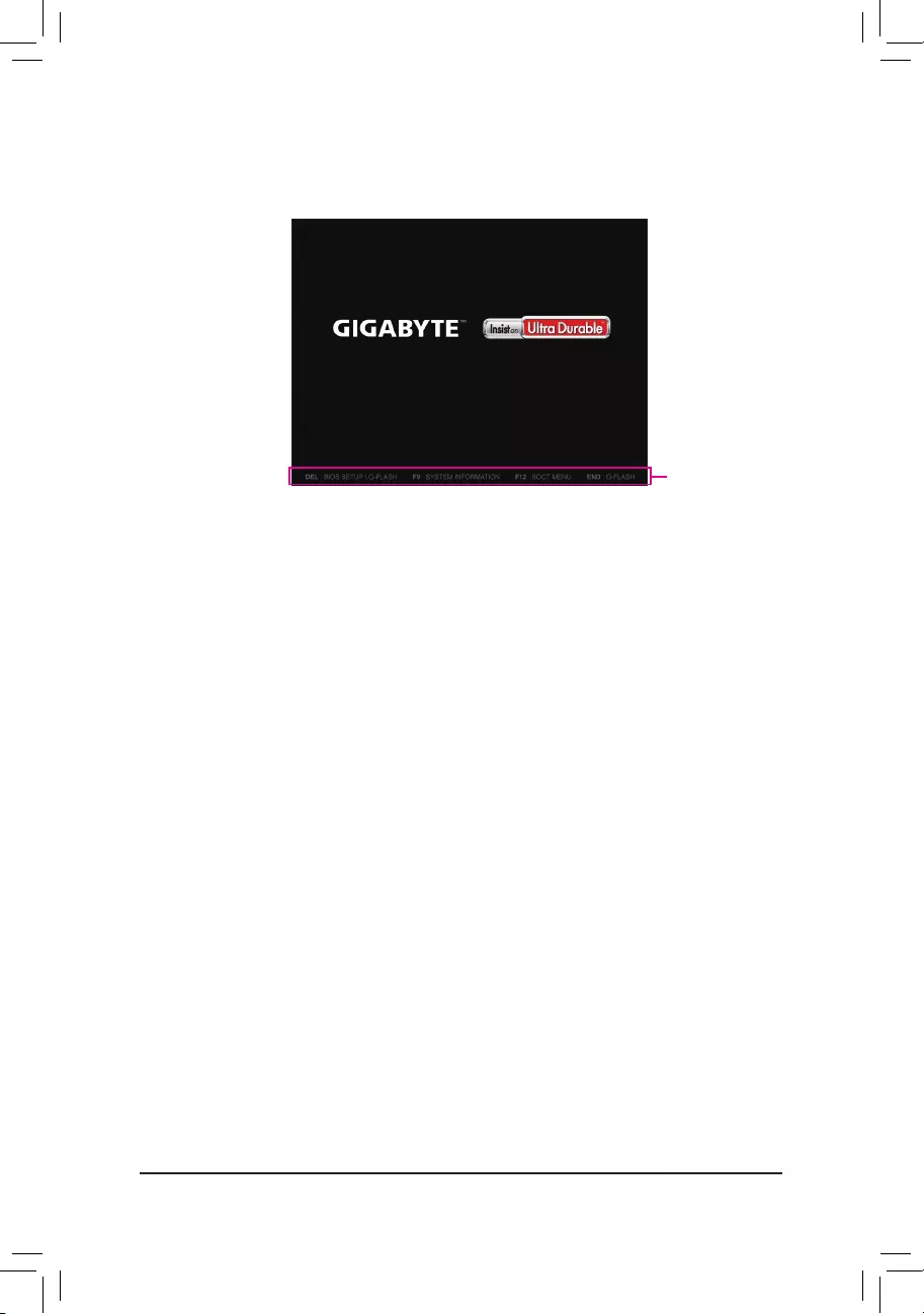
— 32 —
2-1 Startup Screen
The following startup Logo screen will appear when the computer boots.
Function Keys:
<DEL>: BIOS SETUP\Q-FLASH
Press the <Delete> key to enter BIOS Setup or to access the Q-Flash utility in BIOS Setup.
<F9>: SYSTEM INFORMATION
Press the <F9> key to display your system information.
<F12>: BOOT MENU
BootMenuallowsyoutosettherstbootdevicewithoutenteringBIOSSetup.InBootMenu,usetheup
arrow key <h> or the down arrow key <i>toselecttherstbootdevice,thenpress<Enter>toaccept.
The system will boot from the device immediately.
Note: The setting in Boot Menu is effective for one time only. After system restart, the device boot order
will still be based on BIOS Setup settings.
<END>: Q-FLASH
Pressthe<End>keytoaccesstheQ-FlashutilitydirectlywithouthavingtoenterBIOSSetuprst.
Function Keys
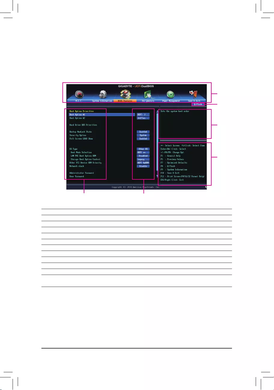
— 33 —
2-2 The Main Menu
The Main Menu
On the main menu of the BIOS Setup program, press arrow keys to move among the items and press <Enter>
to accept or enter a sub-menu. Or you can use your mouse to select the item you want.
(Sample BIOS Version: F1m)
BIOS Setup Program Function Keys
<f><g>Move the selection bar to select a setup menu
<h><i>Movetheselectionbartoselectancongurationitemonamenu
<Enter> Execute command or enter a menu
<+>/<Page Up> Increase the numeric value or make changes
<->/<Page Down> Decrease the numeric value or make changes
<F5> Restore the previous BIOS settings for the current submenus
<F7> LoadtheOptimizedBIOSdefaultsettingsforthecurrentsubmenus
<F8> Access the Q-Flash utility
<F9> Display system information
<F10> Save all the changes and exit the BIOS Setup program
<F12> Capture the current screen as an image and save it to your USB drive
<Esc> Main Menu: Exit the BIOS Setup program
Submenus: Exit current submenu
Setup Menus
Function Keys
Help
Enter Q-Flash
CongurationItems Current Settings

— 34 —
BIOS Setup Menus
M.I.T.
Usethismenutoconguretheclock,frequency,andvoltagesofyourCPUandmemory,etc.Orcheckthe
system/CPU temperatures, voltages, and fan speeds.
System
UsethismenutocongurethedefaultlanguageusedbytheBIOSandsystemtimeanddate.Thismenu
also displays information on the devices connected to the SATA ports.
BIOS Features
Usethismenutocongurethedevicebootorder,advancedfeaturesavailableontheCPU,andtheprimary
display adapter.
Peripherals
Usethismenutocongureallperipheraldevices,suchasSATA,USB,integratedaudio,andintegrated
LAN, etc.
Power Management
Usethismenutocongureallthepower-savingfunctions.
Save & Exit
Save all the changes made in the BIOS Setup program to the CMOS and exit BIOS Setup. You can save
thecurrentBIOSsettingstoaproleorloadoptimizeddefaultsforoptimal-performancesystemoperations.
•When the system is not stable as usual, select the Load Optimized Defaults item to set your
system to its defaults.
•The BIOS Setup menus described in this chapter are for reference only and may differ by BIOS
version.
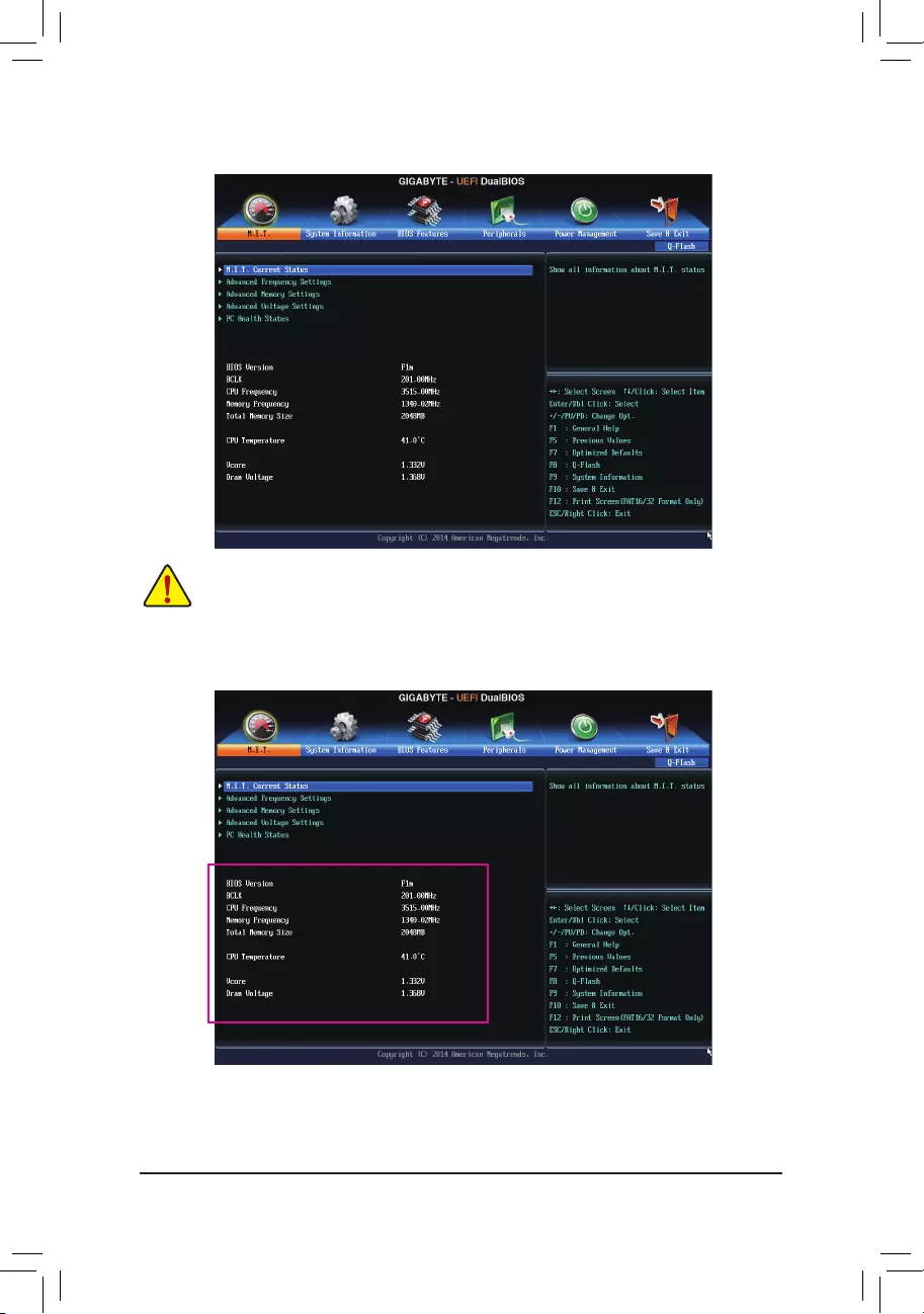
— 35 —
This section provides information on the BIOS version, CPU base clock, CPU frequency, memory frequency,
totalmemorysize,CPUtemperature,Vcore,andmemoryvoltage.
2-3 M.I.T.
Whether the system will work stably with the overclock/overvoltage settings you made is dependent
onyouroverallsystemcongurations.Incorrectlydoingoverclock/overvoltagemayresultindamage
to CPU, chipset, or memory and reduce the useful life of these components. This page is for advanced
users only and we recommend you not to alter the default settings to prevent system instability or
otherunexpectedresults.(Inadequatelyalteringthesettingsmayresultinsystem’sfailuretoboot.If
thisoccurs,cleartheCMOSvaluesandresettheboardtodefaultvalues.)
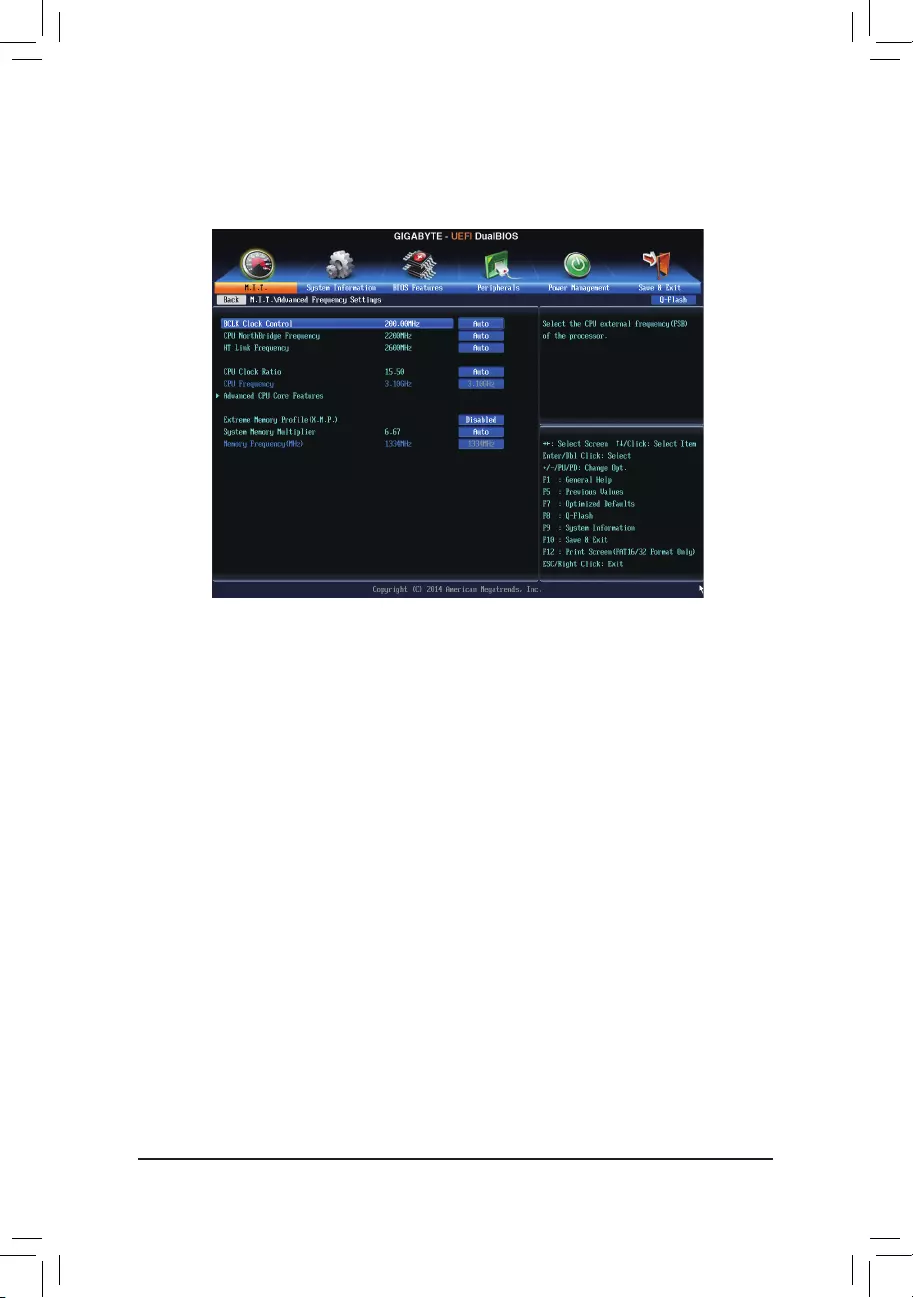
— 36 —
`M.I.T. Current Status
This screen provides information on CPU/memory frequencies/parameters.
`Advanced Frequency Settings
&BCLK Clock Control
AllowsyoutomanuallysettheCPUbaseclockin1MHzincrements.(Default:Auto)
Important: It is highly recommended that the CPU frequency be set in accordance with the CPU
specications.
&CPU NorthBridge Frequency
Allows you to alter the North Bridge controller frequency for the installed CPU. The adjustable range is
dependent on the CPU being used.
&HT Link Frequency
Allows you to manually set the frequency for the HT Link between the CPU and chipset. The adjustable
rangeisfrom200MHzto3200MHz.(Default:Auto)
&CPU Clock Ratio
Allows you to alter the clock ratio for the installed CPU. The adjustable range is dependent on the CPU
being installed.
&CPU Frequency
Displays the current operating CPU frequency.
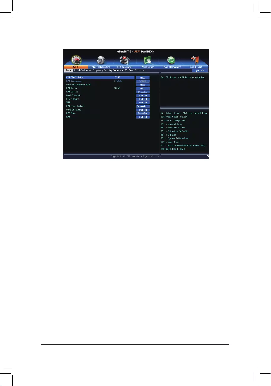
— 37 —
(Note) ThisitemispresentonlywhenyouinstallaCPUthatsupportsthisfeature.
&CPU Clock Ratio, CPU Frequency
The settings above are synchronous to those under the same items on the Advanced Frequency Settings
menu.
&Core Performance Boost (Note)
Allowsyouto determine whether to enabletheCore Performance Boost (CPB)technology, a CPU
performance-boosttechnology.(Default:Auto)
&CPB Ratio (Note)
Allows you alter the ratio for the CPB. The adjustable range is dependent on the CPU being installed.
(Default:Auto)
&CPU Unlock (Note)
AllowsyoutodeterminewhetherunlockhiddenCPUcores.(Default:Disabled)
&Cool&Quiet
Enabled Lets the AMD Cool’n’Quiet driver dynamically adjust the CPU clock and VID to reduce
heatoutputfromyourcomputeranditspowerconsumption.(Default)
Disabled Disables this function.
&C1E Support
Allows you to determine whether to let the CPU enter C1 mode in system halt state. When enabled, the
CPU core frequency and voltage will be reduced during system halt state to decrease power consumption.
(Default:Enabled)
&SVM
VirtualizationenhancedbyVirtualizationTechnologywillallowaplatformtorunmultipleoperatingsystems
andapplicationsinindependentpartitions.Withvirtualization,onecomputersystemcanfunctionasmultiple
virtualsystems.(Default:Enabled)
`Advanced CPU Core Features

— 38 —
&CPU core Control (Note 1)
Allows you to determine whether to manually enable/disable CPU cores. Automatic mode allows the BIOS
toenableallCPUcores(numberofcoresavailabledependsontheCPUbeingused).(Default:Automatic
mode)
&Core C6 State (Note 1)
Allows you to determine whether to let the CPU enter C6 mode in system halt state. When enabled, the
CPU core frequency will be reduced during system halt state to decrease power consumption. The C6
stateisamoreenhancedpower-savingstatethanC1.(Default:Enabled)
&HPC Mode (Note 1)
AllowsyoutodeterminewhethertoenableHighPerformanceComputing(HPC)modefortheCPU.Enabled
preventstheCPUfrequencyfrombeingloweredduringsystemhaltstate.(Default:Disabled)
&APM (AMD Application Power Management) (Note 1)
Enabled Dynamically monitors the power consumption of the CPU cores and automatically
optimizestheCPUtoitsbestperformancelevel.(Default)
Disabled Disables this function.
&ExtremeMemoryProle(X.M.P.)(Note 2)
AllowstheBIOStoreadtheSPDdataonXMPmemorymodule(s)toenhancememoryperformancewhen
enabled.
Disabled Disablesthisfunction.(Default)
Prole1 UsesProle1settings.
Prole2(Note2) UsesProle2settings.
&System Memory Multiplier
Allows you to set the system memory multiplier. Auto sets memory multiplier according to memory SPD
data.(Default:Auto)
&Memory Frequency (MHz)
This value is automatically adjusted according to the BCLK Clock Control and System Memory Multiplier
settings.
(Note1) ThisitemispresentonlywhenyouinstallaCPUthatsupportsthisfeature.
(Note2) Thisitemispresentonlywhenyouinstallamemorymodulethatsupportsthisfeature.

— 39 —
(Note) Thisitemispresentonlywhenyouinstallamemorymodulethatsupportsthisfeature.
`Advanced Memory Settings
&ExtremeMemoryProle(X.M.P.)(Note), System Memory Multiplier, Memory Frequency(MHz)
The settings above are synchronous to those under the same items on the Advanced Frequency Settings
menu.
&DRAM Timing Selectable
Quick and Expertallowsthememorytimingsettingsbelowtobecongurable.Optionsare:Auto(default),
Quick, Expert.
&ProleDDRVoltage
When using a non-XMP memory module or ExtremeMemoryProle(X.M.P.) is set to Disabled, the value
isdisplayedaccordingtoyourmemoryspecication.WhenExtremeMemoryProle(X.M.P.) is set to
Prole1 or Prole2, the value is displayed according to the SPD data on the XMP memory.
&ProleVTTVoltage
The value displayed here is dependent on the CPU being used.
&Channel Interleaving
Enables or disables memory channel interleaving. Enabled allows the system to simultaneously access
different channels of the memory to increase memory performance and stability. Auto lets the BIOS
automaticallycongurethissetting.(Default:Auto)
&Rank Interleaving
Enables or disables memory rank interleaving. Enabled allows the system to simultaneously access different
ranks of the memory to increase memory performance and stability. Auto lets the BIOS automatically
congurethissetting.(Default:Auto)
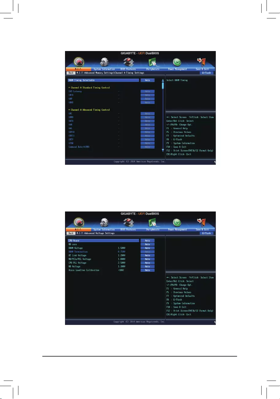
— 40 —
This sub-menu provides memory timing settings for each channel of memory. The respective timing setting
screensarecongurableonlywhenDRAM Timing Selectable is set to Quick or Expert. Note: Your system
may become unstable or fail to boot after you make changes on the memory timings. If this occurs, please reset
theboardtodefaultvaluesbyloadingoptimizeddefaultsorclearingtheCMOSvalues.
`Channel A/B Timing Settings
`Advanced Voltage Settings
This sub-menu allows you to set CPU, Chipset, and memory voltages.
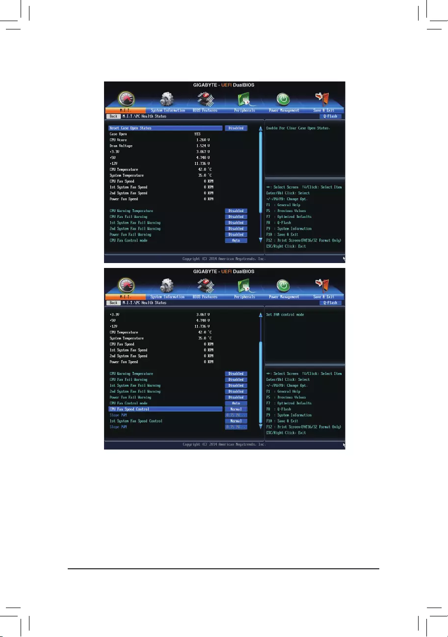
— 41 —
`PC Health Status
&Reset Case Open Status
Disabled Keepsorclearstherecordofpreviouschassisintrusionstatus.(Default)
Enabled Clears the record of previous chassis intrusion status and the Case Openeldwillshow
«No» at next boot.
&Case Open
Displays the detection status of the chassis intrusion detection device attached to the motherboard CI
header.Ifthesystemchassiscoverisremoved,thiseldwillshow»Yes»,otherwiseitwillshow»No».To
clear the chassis intrusion status record, set Reset Case Open Status to Enabled, save the settings to
the CMOS, and then restart your system.

— 42 —
&CPU Vcore/Dram Voltage/+3.3V/+5V/+12V
Displays the current system voltages.
&CPU/System Temperature
Displays current CPU/system temperature.
&CPU/System/Power Fan Speed
Displays current CPU/system/power fan speed.
&CPU Warning Temperature
Sets the warning threshold for CPU temperature. When CPU temperature exceeds the threshold, BIOS
willemitwarningsound.Optionsare:Disabled(default),60oC/140oF, 70oC/158oF, 80oC/176oF, 90oC/194oF.
&CPU/System/Power Fan Fail Warning
Allows the system to emit warning sound if the fan is not connected or fails. Check the fan condition or fan
connectionwhenthisoccurs.(Default:Disabled)
&CPU Fan Control Mode
Auto Lets the BIOS automatically detect the type of CPU fan installed and sets the optimal CPU
fancontrolmode.(Default)
Voltage Sets Voltage mode for a 3-pin CPU fan.
PWM Sets PWM mode for a 4-pin CPU fan.
&CPU Fan Speed Control (CPU_FAN Connector)
Allows you to determine whether to enable the CPU fan speed control function and adjust the fan speed.
Normal Allows the CPU fan to run at different speeds according to the CPU temperature. You can
adjust the fan speed with EasyTune based on your system requirements.(Default)
Silent Allows the CPU fan to run at slow speeds.
Manual Allows you to control the CPU fan speed under the Slope PWM item.
Disabled Allows the CPU fan to run at full speeds.
&Slope PWM
AllowsyoutocontroltheCPUfanspeed.ThisitemiscongurableonlywhenCPU Fan Speed Control is
set to Manual. Options are: 0.75 PWM value /oC ~ 2.50 PWM value /oC.
&1st System Fan Speed Control (SYS_FAN1 Connector)
Allows you to determine whether to enable the system fan speed control function for the system fan
connectedtotheSYS_FAN1connectorandadjustthefanspeed.
Normal Allows the system fan to run at different speeds according to the system temperature. You
canadjustthefanspeedwithEasyTunebasedonyoursystemrequirements.(Default)
Silent Allows the system fan to run at slow speeds.
Manual Allows you to control the system fan speed under the Slope PWM item.
Disabled Allows the system fan to run at full speeds.
&Slope PWM
Allowsyoutocontrolthesystemfanspeed.Thisitemiscongurableonlywhen1st System Fan Speed
Control is set to Manual. Options are: 0.75 PWM value /oC ~ 2.50 PWM value /oC.
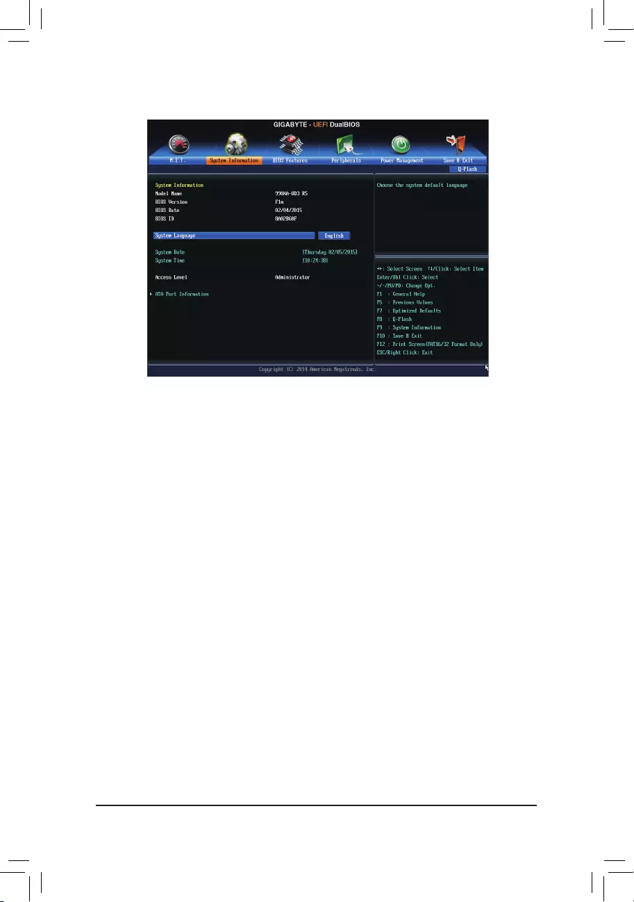
— 43 —
2-4 System Information
This section provides information on your motherboard model and BIOS version. You can also select the default
language used by the BIOS and manually set the system time.
&System Language
Selects the default language used by the BIOS.
&System Date
Setsthesystemdate.Thedateformatisweek(read-only),month,date,andyear.Use<Enter>toswitch
betweentheMonth,Date,andYeareldsandusethe<PageUp>or<PageDown>keytosetthedesired
value.
&System Time
Sets the system time. The time format is hour, minute, and second. For example, 1 p.m. is 13:0:0. Use
<Enter>toswitchbetweentheHour,Minute,andSecondeldsandusethe<PageUp>or<PageDown>
key to set the desired value.
&Access Level
Displaysthecurrentaccessleveldependingonthetypeofpasswordprotectionused.(Ifnopasswordis
set, the default will display as Administrator.)TheAdministratorlevelallowsyoutomakechangestoall
BIOS settings; the User level only allows you to make changes to certain BIOS settings but not all.
`ATA Port Information
This section provides information on the device connected to each SATA port controlled by AMD Chipset.

— 44 —
2-5 BIOS Features
&Boot Option Priorities
Speciestheoverallbootorderfromtheavailabledevices.Forexample,youcansetharddriveasthe
rstpriority(Boot Option #1)andDVDROMdriveasthesecondpriority(Boot Option #2).Thelistonly
displaysthedevicewiththehighestpriorityforaspecictype.Forexample,onlyharddrivedenedasthe
rstpriorityontheHard Drive BBS Priorities submenu will be presented here.
RemovablestoragedevicesthatsupportGPTformatwillbeprexedwith»UEFI:»stringonthebootdevice
list.TobootfromanoperatingsystemthatsupportsGPTpartitioning,selectthedeviceprexedwith«UEFI:»
string.
Or if you want to install an operating system that supports GPT partitioning such as Windows 7 64-bit, select
theopticaldrivethatcontainstheWindows764-bitinstallationdiskandisprexedwith»UEFI:»string.
&Hard Drive/CD/DVD ROM Drive/Floppy Drive/Network Device BBS Priorities
Speciesthebootorderforaspecicdevicetype,suchasharddrives,opticaldrives,oppydiskdrives,
and devices that support Boot from LAN function, etc. Press <Enter> on this item to enter the submenu that
presents the devices of the same type that are connected. This item is present only if at least one device
for this type is installed.
&Bootup NumLock State
EnablesordisablesNumlockfeatureonthenumerickeypadofthekeyboardafterthePOST.(Default:
Enabled)
&Security Option
Specieswhetherapasswordisrequiredeverytimethesystemboots,oronlywhenyouenterBIOSSetup.
Afterconguringthisitem,setthepassword(s)undertheAdministrator Password/User Password item.
Setup A password is only required for entering the BIOS Setup program.
System A password is required for booting the system and for entering the BIOS Setup program.
(Default)
&Full Screen LOGO Show
Allows you to determine whether to display the GIGABYTE Logo at system startup. Disabled skips the
GIGABYTELogowhenthesystemstartsup.(Default:Enabled)

— 45 —
&OS Type
Allowsyoutoselecttheoperatingsystemtobeinstalled.(Default:OtherOS)
&CSM Support
EnablesordisablesUEFICSM(CompatibilitySupportModule)tosupportalegacyPCbootprocess.
Always EnablesUEFICSM.(Default)
Never Disables UEFI CSM and supports UEFI BIOS boot process only.
ThisitemiscongurableonlywhenOS Type is set to Windows 8 or Windows 8 WHQL.
&Boot Mode Selection
Allows you to select which type of operating system to boot.
UEFI and Legacy
Allows booting from operating systems that support legacy option ROM or UEFI
optionROM.(Default)
Legacy Only Allows booting from operating systems that only support legacy Option ROM.
UEFI Only Allows booting from operating systems that only support UEFI Option ROM.
ThisitemiscongurableonlywhenCSM Support is set to Always.
&LAN PXE Boot Option ROM
Allows you to decide whether to enable the legacy option ROM for the LAN controller.
(Default:Disabled)
ThisitemiscongurableonlywhenCSM Support is set to Always.
&Storage Boot Option Control
Allows you to select whether to enable the UEFI or legacy option ROM for the storage device controller.
Disabled Disables option ROM.
LegacyOnly EnableslegacyoptionROMonly.(Default)
UEFI Only Enables UEFI option ROM only.
LegacyFirst EnableslegacyoptionROMrst.
UEFIFirst EnablesUEFIoptionROMrst.
ThisitemiscongurableonlywhenCSM Support is set to Always.
&Other PCI Device ROM Priority
Allows you to select whether to enable the UEFI or Legacy option ROM for the PCI device controller other
than the LAN, storage device, and graphics controllers.
Legacy OpROM Enables legacy option ROM only.
UEFIOpROM EnablesUEFIoptionROMonly.(Default)
&Network stack
Disables or enables booting from the network to install a GPT format OS, such as installing the OS from
theWindowsDeploymentServicesserver.(Default:Disable)
&Ipv4 PXE Support
EnablesordisablesIPv4PXESupport.ThisitemiscongurableonlywhenNetwork stack is enabled.
&Ipv6 PXE Support
EnablesordisablesIPv6PXESupport.ThisitemiscongurableonlywhenNetwork stack is enabled.
&Administrator Password
Allowsyoutocongureanadministratorpassword.Press<Enter>onthisitem,typethepassword,and
thenpress<Enter>.Youwillberequestedtoconrmthepassword.Typethepasswordagainandpress
<Enter>.Youmustentertheadministratorpassword(oruserpassword)atsystemstartupandwhenentering
BIOS Setup. Differing from the user password, the administrator password allows you to make changes to
all BIOS settings.

— 46 —
&User Password
Allowsyoutocongureauserpassword.Press<Enter>onthisitem,typethepassword,andthenpress
<Enter>.Youwillberequestedtoconrmthepassword.Typethepasswordagainandpress<Enter>.
Youmustentertheadministratorpassword(oruserpassword)atsystemstartupandwhenenteringBIOS
Setup. However, the user password only allows you to make changes to certain BIOS settings but not all.
To cancel the password, press <Enter> on the password item and when requested for the password, enter
thecorrectonerst.Whenpromptedforanewpassword,press<Enter>withoutenteringanypassword.
Press<Enter>againwhenpromptedtoconrm.
NOTE:BeforesettingtheUserPassword,besuretosettheAdministratorPasswordrst.
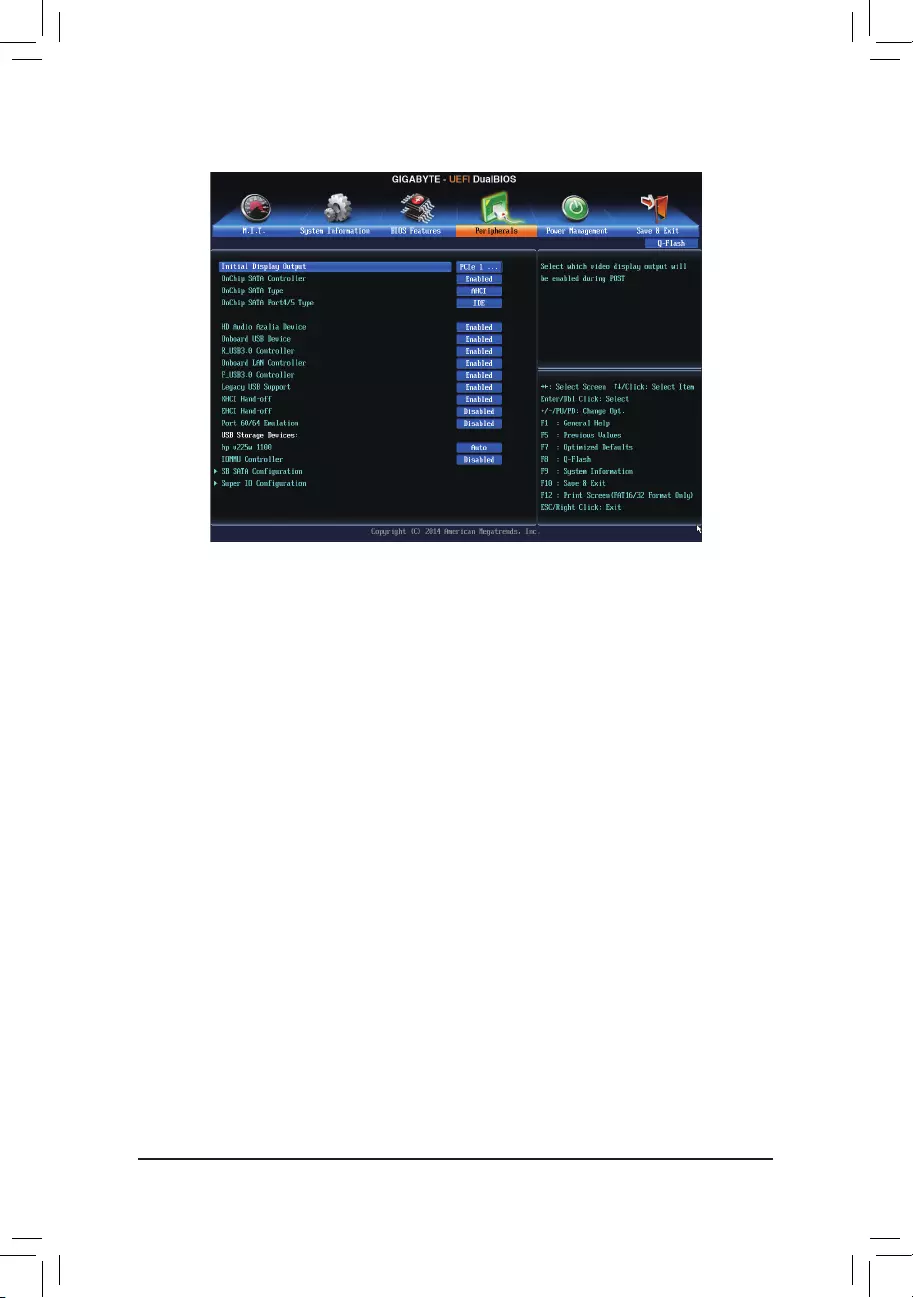
— 47 —
2-6 Peripherals
&Initial Display Output
SpeciestherstinitiationofthemonitordisplayfromtheinstalledPCIgraphicscardorthePCIExpress
graphics card.
PCIe1Slot SetsthePCIExpressgraphicscardonthePCIEX16slotastherstdisplay.(Default)
PCIe2Slot SetsthePCIExpressgraphicscardonthePCIEX8slotastherstdisplay.
PCIe3Slot SetsthePCIExpressgraphicscardonthePCIEX4slotastherstdisplay.
PCI1Slot SetsthePCIgraphicscardonthePCI1slotastherstdisplay.
PCI2Slot SetsthePCIgraphicscardonthePCI2slotastherstdisplay.
&OnChip SATA Controller
EnablesordisablestheintegratedSATAcontrollers.(Default:Enabled)
&OnChip SATA Type (SATA3 0~SATA3 3 connectors)
EnablesordisablesRAIDfortheSATAcontrollersintegratedintheAMDChipsetorcongurestheSATA
controllers to RAID mode.
NativeIDE CongurestheSATAcontrollertoIDEmode.
RAID Enables RAID for the SATA controller.
AHCI CongurestheSATAcontrollerstoAHCImode.AdvancedHostControllerInterface
(AHCI)isaninterfacespecicationthatallowsthestoragedrivertoenableadvanced
SerialATAfeaturessuchasNativeCommandQueuingandhotplug.(Default)
&OnChip SATA Port4/5 Type (SATA3 4~SATA3 5 connectors)
ThisoptioniscongurableonlywhenOnChip SATA Type is set to RAID or AHCI.Congurestheoperating
mode of the integrated SATA3 4~SATA3 5 connectors.
As SATA Type The mode depends on the OnChip SATA Type settings.
IDE DisablesRAIDfortheSATAcontrollerandcongurestheSATAcontrollertoIDEmode.
(Default)

— 48 —
&HD Audio Azalia Device
Enablesordisablestheonboardaudiofunction.(Default:Enabled)
If you wish to install a 3rd party add-in audio card instead of using the onboard audio, set this item to
Disabled.
&Onboard USB Device
EnablesordisablestheintegratedUSBcontroller.(Default:Enabled)
&Onboard LAN Controller
EnablesordisablestheonboardLANfunction.(Default:Enabled)
If you wish to install a 3rd party add-in network card instead of using the onboard LAN, set this item to
Disabled.
&Onboard USB3.0 Controller (VIA
®
VL805 USB Controller)
Enables or disables the VIA®VL805USBcontroller.(Default:Enabled)
&Legacy USB Support
AllowsUSBkeyboard/mousetobeusedinMS-DOS.(Default:Enabled)
&XHCI Hand-off
Determines whether to enable XHCI Hand-off feature for an operating system without XHCI Hand-off
support.(Default:Enabled)
&EHCI Hand-off
Determines whether to enable EHCI Hand-off feature for an operating system without EHCI Hand-off
support.(Default:Disabled)
&Port 60/64 Emulation
Enables or disables emulation of I/O ports 64h and 60h. This should be enabled for full legacy support
for USB keyboards/mice in MS-DOS or in operating system that does not natively support USB devices.
(Default:Disabled)
&USB Storage Devices
Displays a list of connected USB mass storage devices. This item appears only when a USB storage device
is installed.
&IOMMU Controller
EnablesordisablesAMDIOMMUsupport.(Default:Enabled)
`Trusted Computing
&TPM SUPPORT
EnablesordisablesTrustedPlatformModule(TPM).SetthisitemtoEnable when a TPM device is installed.
(Default:Disable)
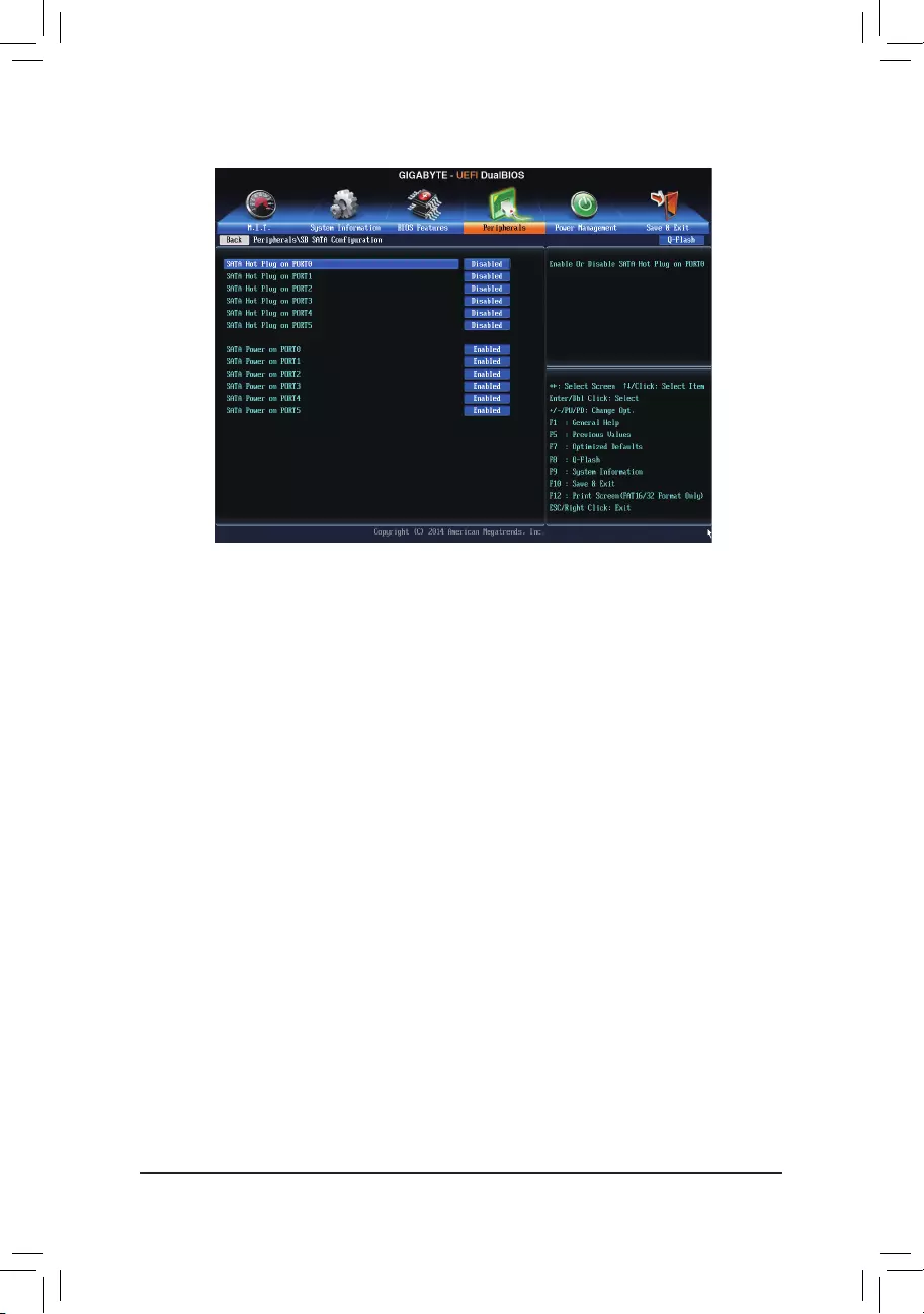
— 49 —
`SBSATAConguration
&SATA Hot Plug on PORT0~SATA Hot Plug on PORT5
Enables or disable the hot plug capability for each SATA port. (Default:Disabled)
&SATA Power on PORT0~SATA Power on PORT5
Enables or disables each SATA port. (Default:Enabled)
`SuperIOConguration
ThissectionprovidesinformationonthesuperI/Ochipandallowsyoutoconguretheserialport.
&Serial Port A
Enablesordisablestheonboardserialport.(Default:Enabled)
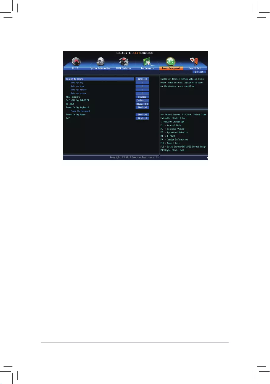
— 50 —
&Resume by Alarm
Determineswhethertopoweronthesystematadesiredtime.(Default:Disabled)
If enabled, set the date and time as following:
Wakeupday:Turnonthesystemataspecictimeoneachdayoronaspecicdayinamonth.
Wake up hour/minute/second: Set the time at which the system will be powered on automatically.
Note: When using this function, avoid inadequate shutdown from the operating system or removal of the
AC power, or the settings may not be effective.
&HPET Support
EnablesordisablesHighPrecisionEventTimer(HPET)forWindows8.1/8/7operatingsystem.(Default:
Enabled)
&Soft-Off by PWR-BTTN
ConguresthewaytoturnoffthecomputerinMS-DOSmodeusingthepowerbutton.
Instant-Off Pressthepowerbuttonandthenthesystemwillbeturnedoffinstantly.(Default)
Delay 4 Sec Press and hold the power button for 4 seconds to turn off the system. If the power
button is pressed for less than 4 seconds, the system will enter suspend mode.
&AC BACK
Determines the state of the system after the return of power from an AC power loss.
Memory The system returns to its last known awake state upon the return of the AC power.
Always On The system is turned on upon the return of the AC power.
AlwaysOff ThesystemstaysoffuponthereturnoftheACpower.(Default)
2-7 Power Management

— 51 —
&Power On By Keyboard
Allows the system to be turned on by a PS/2 keyboard wake-up event.
Note: To use this function, you need an ATX power supply providing at least 1A on the +5VSB lead.
Disabled Disablesthisfunction.(Default)
Password Set a password with 1~5 characters to turn on the system.
Keyboard 98 Press POWER button on the Windows 98 keyboard to turn on the system.
Any Key Press any key to turn on the system.
&Power On Password
Set the password when Power On By Keyboard is set to Password.
Press <Enter> on this item and set a password with up to 5 characters and then press <Enter> to accept.
To turn on the system, enter the password and press <Enter>.
Note: To cancel the password, press <Enter> on this item. When prompted for the password, press <Enter>
again without entering the password to clear the password settings.
&Power On By Mouse
Allows the system to be turned on by a PS/2 mouse wake-up event.
Note: To use this function, you need an ATX power supply providing at least 1A on the +5VSB lead.
Disabled Disablesthisfunction.(Default)
Move Move the mouse to turn on the system.
Double Click Double click on left button on the mouse to turn on the system.
&ErP
DetermineswhethertoletthesystemconsumeleastpowerinS5(shutdown)state.(Default:Disabled)
Note: When this item is set to Enabled, the following functions will become unavailable: Resume by Alarm,
PME event wake up, power on by mouse, power on by keyboard, and wake on LAN.
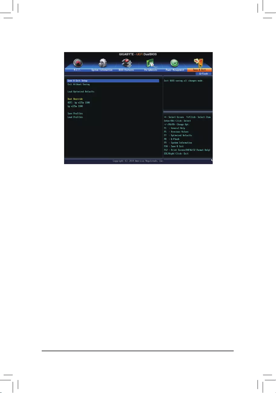
— 52 —
2-8 Save & Exit
&Save & Exit Setup
Press <Enter> on this item and select Yes. This saves the changes to the CMOS and exits the BIOS Setup
program. Select No or press <Esc> to return to the BIOS Setup Main Menu.
&Exit Without Saving
Press <Enter> on this item and select Yes. This exits the BIOS Setup without saving the changes made
in BIOS Setup to the CMOS. Select No or press <Esc> to return to the BIOS Setup Main Menu.
&Load Optimized Defaults
Press <Enter> on this item and select Yes to load the optimal BIOS default settings. The BIOS defaults
settingshelpthesystemtooperateinoptimumstate.AlwaysloadtheOptimizeddefaultsafterupdating
the BIOS or after clearing the CMOS values.
&Boot Override
Allows you to select a device to boot immediately. Press <Enter> on the device you select and select Yes
toconrm.Yoursystemwillrestartautomaticallyandbootfromthatdevice.
&SaveProles
ThisfunctionallowsyoutosavethecurrentBIOSsettingstoaprole.Youcancreateupto8prolesand
saveasSetupProle1~SetupProle8.Press<Enter>tocomplete.OryoucanselectSelect File in
HDD/USB/FDDtosavetheproletoyourstoragedevice.
&LoadProles
If your system becomes unstable and you have loaded the BIOS default settings, you can use this function
toloadtheBIOSsettingsfromaprolecreatedbefore,withoutthehasslesofreconguringtheBIOS
settings.Firstselecttheproleyouwishtoloadandthenpress<Enter>tocomplete.YoucanselectSelect
File in HDD/USB/FDDtoinputtheprolepreviouslycreatedfromyourstoragedeviceorloadtheprole
automatically created by the BIOS, such as reverting the BIOS settings to the last settings that worked
properly(lastknowngoodrecord).

— 53 —
Conguring SATA Hard Drive(s)
Chapter3 ConguringSATAHardDrive(s)
(Note1) SkipthisstepifyoudonotwanttocreateRAIDarrayontheSATAcontroller.
(Note2) RequiredwhentheSATAcontrollerissettoAHCIorRAIDmode.
RAID 0 RAID 1 RAID 5 RAID 10
Minimum
Number of Hard
Drives
≥2 2≥3 ≥4
Array Capacity Number of hard
drives*Sizeofthe
smallest drive
Sizeofthesmallest
drive
(Numberofhard
drives-1)*Sizeof
the smallest drive
(Numberofhard
drives/2)*Sizeofthe
smallest drive
Fault Tolerance No Yes Yes Yes
RAID Levels
TocongureSATAharddrive(s),followthestepsbelow:
A. InstallSATAharddrive(s)inyourcomputer.
B. CongureSATAcontrollermodeinBIOSSetup.
C. CongureaRAIDarrayinRAIDBIOS(Note1)
D. Install the SATA RAID/AHCI driver and operating system (Note2)
Before you begin
•AtleasttwoSATAharddrives(toensureoptimalperformance,itisrecommendedthatyouusetwoharddrives
withidenticalmodelandcapacity).IfyoudonotwanttocreateRAID,youmayprepareonlyoneharddrive.
•Windows setup disk.
•Motherboard driver disk.
•AUSBashdrive.
3-1 ConguringSATAControllers
A. Installing SATA hard drive(s) in your computer
Attach one end of the SATA signal cable to the rear of the SATA hard drive and the other end to available SATA
port on the motherboard. Then connect the power connector from your power supply to the hard drive.
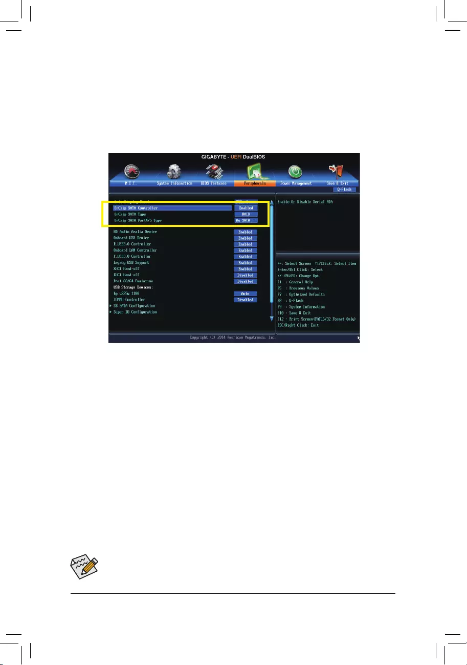
Conguring SATA Hard Drive(s)
— 54 —
The BIOS Setup menus described in this section may differ from the exact settings for your motherboard.
The actual BIOS Setup menu options you will see shall depend on the motherboard you have and
the BIOS version.
B.ConguringSATAcontrollermodeinBIOSSetup
MakesuretoconguretheSATAcontrollermodecorrectlyinsystemBIOSSetup.
Step 1:
Turnonyourcomputerandpress<Delete>toenterBIOSSetupduringthePOST(Power-OnSelf-Test).Ensure
OnChip SATA Controller is enabled under Peripherals. To enable RAID for the SATA3 0/1/2/3 connectors, set
OnChip SATA Type to RAID. To enable RAID for the SATA3 4/SATA3 5 connectors, set OnChip SATA Type
to RAID and set OnChip SATA Port4/5 Type to As SATA Type.
Figure 1
Step 2:
IfyouwanttocongureUEFIRAID,followthestepsin«C-1.»ToenterthelegacyRAIDROM,savethesettings
and exit BIOS Setup. Refer to «C-2» for more information.
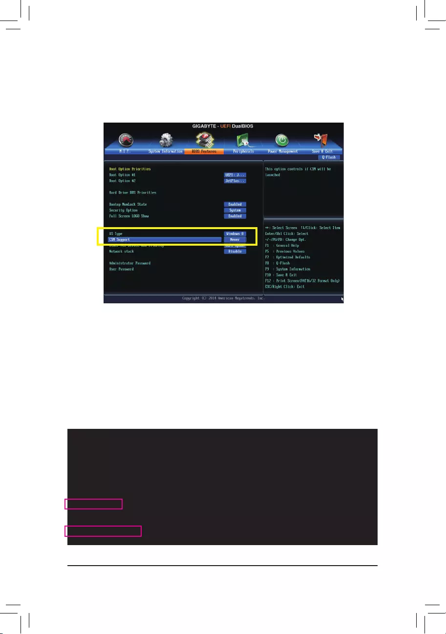
— 55 —
Conguring SATA Hard Drive(s)
C-1.UEFIRAIDConguration
This mode supports Windows 8.1/8 64-bit installation only.
Step 1:
In BIOS Setup, go to BIOS Features and set OS Type to Windows 8 and CSM Support to Never.(Figure2)
Save the changes and exit BIOS Setup.
Step 2:
Restartyourcomputerandpress<F12>toenterthebootdevicecongurationmenu.Usetheupordownarrow
key to select UEFI: Built-in EFI Shell. Press <Enter> to access the screen as shown in Figure 3. Follow the
steps below and enter the commands to access the RAID setup utility.
1. Enter drvcfg at Shell and press <Enter>:
Shell> drvcfg
2. When Drv [XX] Ctrl [XX] Lang [eng] appears, enter the following commands at Shell again:
Shell> drvcfg -s XX XX
(XXs are the values shown in the brackets after Drv and Ctrlabove,whichmayvarybyharddrives.)
Then press <Enter> to enter the RAID setup utility.
Figure 2
Figure 3
EFI Shell version 2.31 [4.653]
Current running mode 1.1.2
Device mapping table
fs0 : Removable HardDisk Alias hd12d0b blk0
PciRoot (0x0)/Pci (0x10, 0x0)/USB (0x3, 0x0)/HD (1.MBR,0x016777a6, 0x3f, 0x1e1fc0)
fs1 : Removable CDRom Alias cd14c0b blk1
PciRoot (0x0)/Pci (0x11, 0x0)/Scsi (0x2, 0x0)/CDROM (0x1,0x6e, 0X1A0263)
……
Press ESC in 1 seconds to skip startup.nsh, any other key to continue.
Shell> drvcfg
Congurable Components
Drv [59] Ctrl [CF] Lang [eng]
Shell> drvcfg -s 59 cf
Conguring SATA Hard Drive(s)
— 56 —
Step 3:
The Main MenuistherstscreenwhenyouentertheBIOSRAIDSetuputility.Usetheupordownarrowkey
to select Logical Drive Main Menu and press <Enter>.
Figure 4
Figure 5
RAID Utility (C) 2012 Advanced Micro Devices, Inc. [Rev. 1.0.0.45]
F10=Exit Utility
hi=Move Highlight <Enter>=Select Option Esc=Previous Page
+ Main Menu
+ Driver Information Menu
+ Physical Device Main Menu
+ Logical Drive Main Menu
To View Or Congure The Logical Drive
Step 4:
To create an array, press <Enter> on Logical Drive Create Menu.
RAID Utility (C) 2012 Advanced Micro Devices, Inc. [Rev. 1.0.0.45]
F10=Exit Utility
hi=Move Highlight <Enter>=Select Option Esc=Previous Page
+ Logical Drive Main Menu
+ Logical Drive List Menu
+ Logical Drive Create Menu
+ Logical Drive Delete Menu
To Create The Logical Drive
— 57 —
Conguring SATA Hard Drive(s)
Step 5:
Usable hard drives are listed on the Logical Drive Create Menu. Use the up or down arrow key to select the
hard drive to be included in the array and press the <Space> key. The selected hard drives will be marked with
[X]. Then move to Basic Setting and press <Enter>.
Step 6:
Usetheupordownarrowkeytomovetoandcongureeachrequirediteminsequence.
After completing, press <Enter> on Start To Create(Figure7).Whenthemessage«AreYouSureToCreate
Logical Drive?» appears, press <Enter> to begin creating the RAID array or <Esc> to cancel.
When completed, a message which says «Successful To Create Logical Drive» will appear. Press <Enter> to
complete. Press <F10> to exit the RAID setup utility.
Figure 6
Figure 7
RAID Utility (C) 2012 Advanced Micro Devices, Inc. [Rev. 1.0.0.45]
F10=Exit Utility
hi=Move Highlight <Space>=Toggle Checkbox Esc=Previous Page
+ Logical Drive Create Menu
+ Usable Physical Drive List
— Hitachi HDT721032SLA360 | 500.10 GB [X]
— Hitachi HDT721032SLA360 | 500.10 GB [X]
+ Basic Setting
Usable Physical Disk On
(Port : 4, TargetId : 1)
RAID Utility (C) 2012 Advanced Micro Devices, Inc. [Rev. 1.0.0.45]
F10=Exit Utility
hi=Move Highlight <Enter>=Select Option Esc=Previous Page
+ Logical Drive Create Menu
— Raid Mode : <RAID 0>
— Stripe Block (KB) : <64>
— Setcor Size (Bytes) : <512>
— Initialization : <Fast>
— Gigabyte Boundary : <Enable>
— Read Policy : <Read Ahead>
— Write Policy : <Write Back>
— Ld Name : GBT
+ Ld Size Setting
— Ld Max Size : 1000.21 GB
— Ld Size (GB) : [0]
+ Start To Create
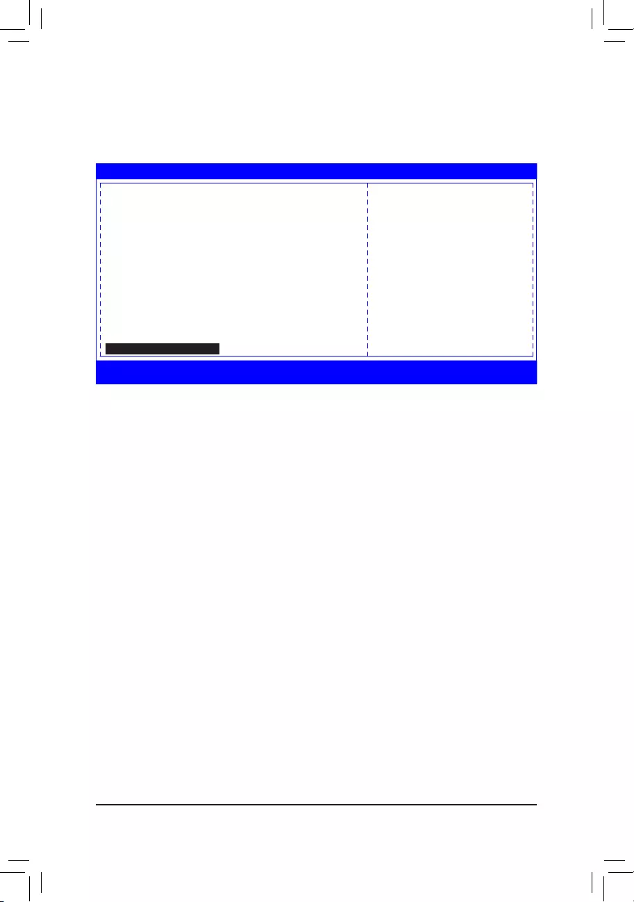
Conguring SATA Hard Drive(s)
— 58 —
Figure 8
Delete an Array
To delete an array, select Logical Drive Delete Menu on the Logical Drive Main Menu and press <Enter> to
access the screen as shown in Figure 8. Then press <Enter> on Start To Delete. When the message «Are You
Sure To Delete Logical Drive?» appears, press <Enter> to delete or <Esc> to cancel.
RAID Utility (C) 2012 Advanced Micro Devices, Inc. [Rev. 1.0.0.45]
F10=Exit Utility
hi=Move Highlight Esc=Previous Page
+ Logical Drive Information
— Ld Id : 2
— Ld Name : GBT
— Raid Mode : RAID 0
— Ld Size : 999.99 GB
— SB Size : 64
— Sector Size : 512
— Read Policy : Read Ahead
— Write Policy : Write Bact
— Ld Status : Functional
— Bga State : None
— Bga Type : None
+ Logical Drive Member List
— Hitachi HDT721032SLA360 | 500.40 GB
— Hitachi HDT721032SLA360 | 500.40 GB
+ Start To Delete

— 59 —
Conguring SATA Hard Drive(s)
C-2.ConguringLegacyRAIDROM
EntertheRAIDBIOSsetuputilitytocongureaRAIDarray.SkipthisstepifyoudonotwanttocreateRAID
array on the SATA controller.
Step 1:
After the POST memory test begins and before the operating system boot begins, look for a message which
says»Press<Ctrl-F>toenterRAIDOptionROMUtility»(Figure2).Press<Ctrl>+<F>toentertheRAIDBIOS
setup utility.
Figure 2
Step 2:
Main Menu
ThisistherstoptionscreenwhenyouentertheBIOSRAIDSetuputility.(Figure3)
To view the disk drives assigned to arrays, press <1> to enter the View Drive Assignments window.
To create an array, press <2> to enter the LDView/LDDeneMenu window.
To delete an array, press <3> to enter the Delete LD Menu window.
To view controller settings, press <4> to enter the ControllerConguration window.
Figure 3
RAID Option ROM Version 3.3.1540.17
(c) 2011 Advanced Micro Devices, Inc. All rights reserved.
No Array is dened..
Press <Ctrl-F> to enter RAID Option ROM Utility…
View Drive Assignments……………………… [ 1 ]
LD View/ LD Dene Menu…………………. [ 2 ]
Delete LD Menu………………………………… [ 3 ]
Controller Conguration………………………. [ 4 ]
Option ROM Utility (c) 2011 Advanced Micro Devices, Inc.
Press 1..4 to Select Option [ESC] Exit
[ Keys Available ]
[ Main Menu ]
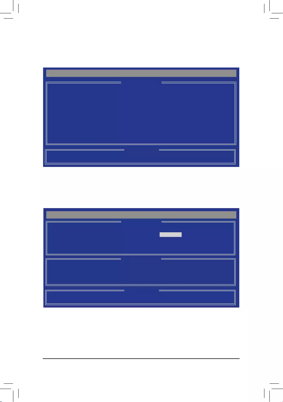
Conguring SATA Hard Drive(s)
— 60 —
In the LDDeneMenu,usetheupordownarrowkeytomovetoanitemforfurtherconguration(Figure5).
Figure 4
Figure 5
Create a RAID Array
To create a new array, press <2> to enter the LD View Menuwindow(Figure4).Tocreateanarray,press
<Ctrl+C> to access the LDDeneMenu.
Option ROM Utility (c) 2011 Advanced Micro Devices, Inc.
[ LD View Menu ]
< There is no any LD >
[h] Up [i] Down [PaUp/PaDn] Switch Page [Ctrl+C] Dene LD
[Enter] View LD [Ctrl+V] View Single Disk [ESC] Exit
[ Keys Available ]
[ Keys Available ]
Option ROM Utility (c) 2011 Advanced Micro Devices, Inc.
[ LD Dene Menu ]
[h] Up [i] Down [PaUp/PaDn] Switch Page [Space] Change Option
[Ctrl+Y] Save [ESC] Exit
[ Keys Available ]
[ Drives Assignments ]
Port:ID Drive Model Capabilities Capacity (GB) Assignment
01:00 WDC WD800JD-22LSA0 SATA 3G 79.89 N
02:00 WDC WD800JD-22LSA0 SATA 3G 80.02 N
LD No LD Name RAID Mode Drv
LD 1 Logical Drive 1 RAID 0 0
Stripe Block 64 KB Initialization Fast
Gigabyte Boundary ON
Read Policy Read Ahead Write Policy WriteBack

— 61 —
Conguring SATA Hard Drive(s)
In the following procedure, we’ll create RAID 0 as an example.
Steps:
1. Under the RAID Mode section, press the <SPACE> key to select RAID 0.
2. Set the Stripe Blocksize.64KBisthedefault.
3. Under the Drives Assignments section, press the up or down arrow key to highlight a drive.
4. Press the <SPACE> key or <Y> to change the Assignment option to Y. This action adds the drive to the
disk array. The Drv section will show the number of disks assigned.
5. Press <Ctrl>+<Y> keys to save the information. The message in Figure 6 will appear. Press <Ctrl>+<Y> to
input the array name. If you do not input the array name, the default array name will be used.
Figure 7
Figure 8
7. Press <Ctrl>+<Y> to set the capacity of the RAID array or press other keys to set the array to its maximum
capacity.
8. After the creation is complete, the screen will return to LD View Menu where you will see the newly-created
array.
9. Press <Esc> to return to Main Menu and press <Esc> again if you want to exit the RAID BIOS utility.
Fast Initialization Option has been selected
It will erase the MBR data of the disk.
<Press Ctrl-Y Key if you are sure to erase it>
<Press any other key to ignore this option>
Press Ctrl-Y to Modify Array Capacity or press any
other key to use maximum capacity…
Figure 6
Please press Ctrl-Y key to input the LD Name
or press any key to exit.
If you do not input any LD name, the default
LD name will be used.
6. When the next message appears, press <Ctrl>+<Y> to clear the MBR or press other keys to ignore this
option. Then, the message in Figure 8 will appear.

Conguring SATA Hard Drive(s)
— 62 —
Delete an Array
The Delete Array menu option allows for deletion of disk array assignments.
1. To delete an array, press <3> in the Main Menu to enter the Delete LD Menu. Then highlight the array you
wish to delete and press the <Delete> key or the <Alt>+<D> keys.
2. The View LD Denition Menu will appear (as shown in Figure 10) showing which drives are assigned to
this array. Press <Ctrl>+<Y> if you are sure to delete the array or other keys to abort.
3. When the array is deleted, the screen will return to Delete LD Menu. Press <Esc>to return to Main Menu.
Figure 10
Deleting an existing disk array could result in loss of data. Record all array information including the
array type, the disk members, and stripe block size in case you wish to undo a deletion.
View Drive Assignments
The View Drive Assignments option in the Main Menu displays whether the attached hard drives are assigned
to a disk array or are unassigned. Under the Assignment column, drives are labeled with their assigned disk
array or shown as Free if unassigned.
Figure 9
Option ROM Utility (c) 2011 Advanced Micro Devices, Inc.
[ Keys Available ]
[ View Drives Assignments ]
[h] Up [i] Down [PaUp/PaDn] Switch Page [Ctrl+H] Secure Erase
[ESC] Exit
Port:ID Drive Model Capabilities Capacity (GB) Assignment
01:00 WDC WD800JD-22LSA0 SATA 3G 79.89
[S.M.A.R.T.] Health
Extent 1 79.82 LD 1-1
02:00 WDC WD800JD-22LSA0 SATA 3G 80.2
[S.M.A.R.T.] Health
Extent 1 80.02 LD 1-2
[ Keys Available ]
Option ROM Utility (c) 2011 Advanced Micro Devices, Inc.
[ View LD Denition Menu ]
[ Keys Available ]
[ Drives Assignments ]
Port:ID Drive Model Capabilities Capacity (GB)
01:00 WDC WD800JD-22LSA0 SATA 3G 79.89
02:00 WDC WD800JD-22LSA0 SATA 3G 80.02
Press Ctrl-Y to delete the data in the disk!
or press any other key to abort…
LD No LD Name RAID Mode Drv Capacity(GB)
LD 1 GBT RAID 0 2 80
Stripe Block 64 KB Sector Size 512 B
Read Policy Read Ahead Write Policy WriteBack
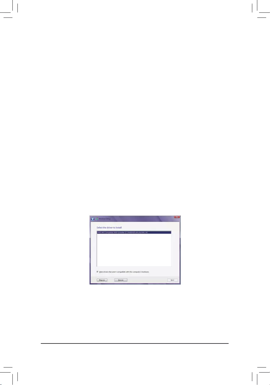
— 63 —
Conguring SATA Hard Drive(s)
3-2 Installing the SATA RAID/AHCI Driver and Operating System
With the correct BIOS settings, you are ready to install the operating system.
A. Installing Windows
(ThefollowinginstructionsuseWindows8.1astheexampleoperatingsystem.)
Step 1:
You need to install the SATA RAID/AHCI driver during the OS installation. Use an alternative system to copy
theSATARAID/AHCIdriverfromthemotherboarddriverdisktoaUSBashdrive.CopytheHw8 folder under
BootDrv in the driver disk.
Step 2:
Boot from the Windows setup disk and perform standard OS installation steps. When the screen requesting you
to load the driver appears, select Browse.
Step 3:
ThenbrowsetotheUSBashdriveandselectthelocationofthedriver.Thelocationsofthedriversareasfollows:
RAID driver for Windows 8.1 32-bit: Hw8\RAID\x86
RAID driver for Windows 8.1 64-bit: Hw8\RAID\x64
AHCI driver for Windows 8.1 32-bit: Hw8\AHCI\W8
AHCI driver for Windows 8.1 64-bit: Hw8\AHCI\W864A
For Windows 7, browse to the Hw7 folder.
Step 4:
When a screen as shown in Figure 1 appears, select AMD AHCI Compatible RAID Controller and click Next
to load the driver and continue the OS installation.
Figure 1
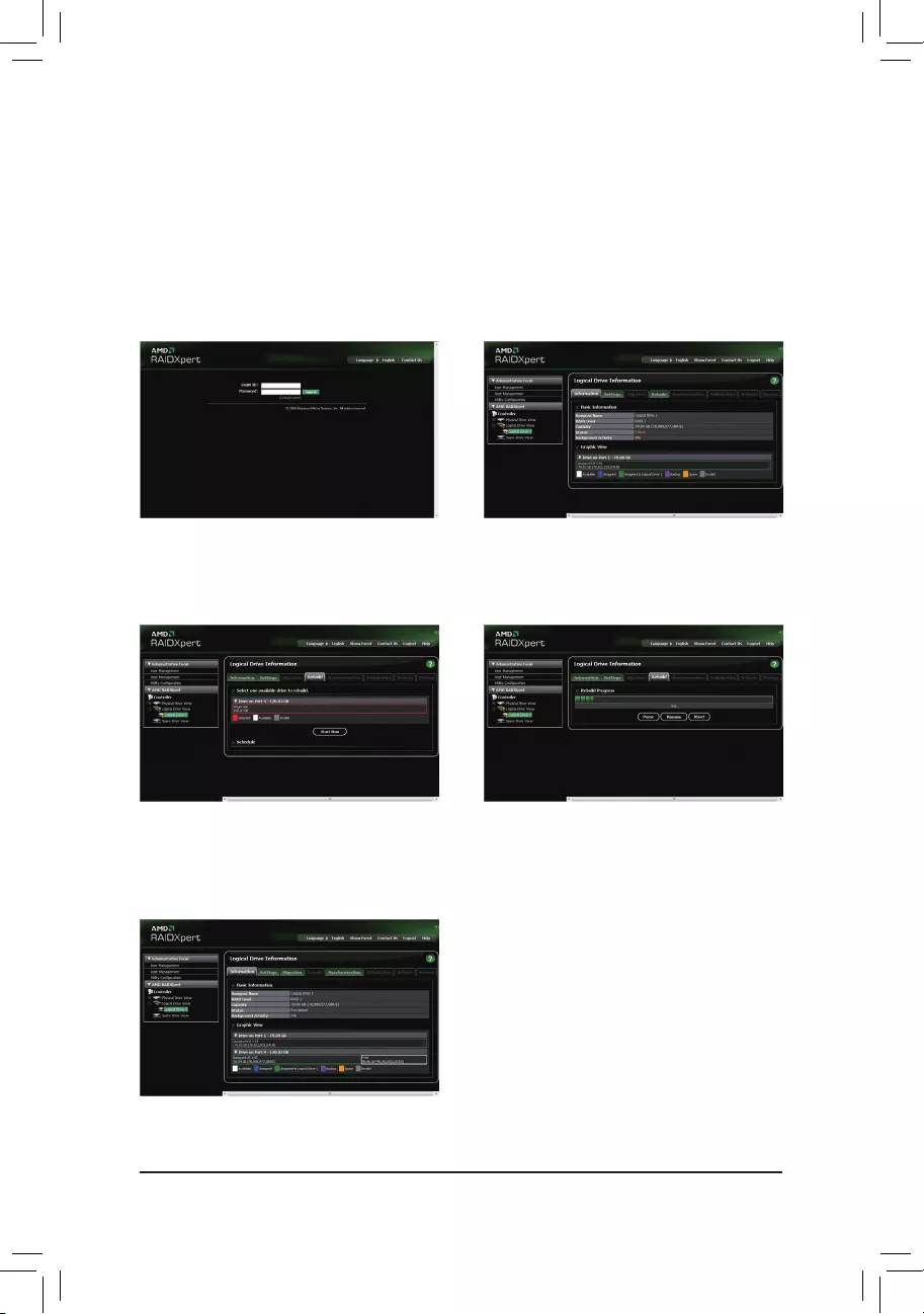
Conguring SATA Hard Drive(s)
— 64 —
Rebuilding an Array:
Rebuilding is the process of restoring data to a hard drive from other drives in the array. Rebuilding applies
only to fault-tolerant arrays such as RAID 1, RAID 5, and RAID 10 arrays. To replace the old drive, make sure
to use a new drive of equal or greater capacity. The procedures below assume a new drive is added to replace
a failed drive to rebuild a RAID 1 array.
While in the operating system, make sure the Chipset driver has been installed from the motherboard driver
disk.TheninstalltheAMDRAIDUtility(gotoApplicationSoftware\InstallApplicationSoftwareandselectAMD
RAID Utilitytoinstall).ThenlaunchtheAMDRAIDXpertfromAllProgramsintheStartMenu.
Step 1:
EntertheloginIDandpassword(default:»admin»),
and then click Sign in to launch AMD RAIDXpert.
Step 2:
Select the RAID array to be rebuilt under Logical
Drive View and click the Rebuild tab in the Logical
Drive Information pane.
Step 3:
Select one available drive and click Start Now to
start the rebuilding process.
Step 4:
The rebuilding progress is displayed on the screen
and you can select Pause/Resume/Abort during
the rebuilding process.
Step 5:
When done, the array’s status on the Information page
in the Logical Drive Information pane will display as
Functional.
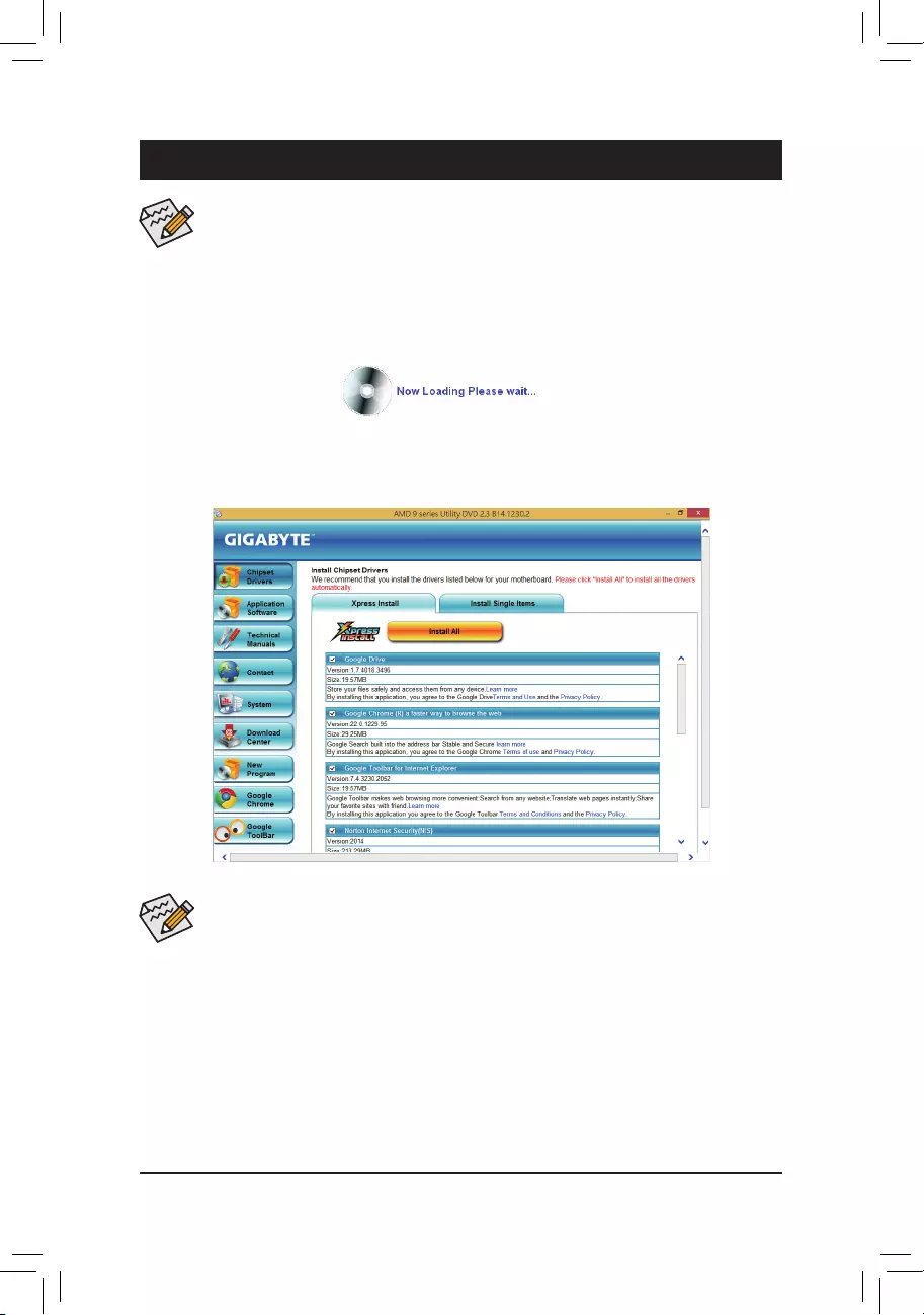
— 65 — Drivers Installation
4-1 Installing Chipset Drivers
Chapter 4 Drivers Installation
•Beforeinstallingthedrivers,rstinstalltheoperatingsystem.
•After installing the operating system, insert the motherboard driver disk into your optical drive.
The driver Autorun screen is automatically displayed which looks like that shown in the screen
shotbelow.(IfthedriverAutorunscreendoes notappear automatically,goto MyComputer,
double-click the optical drive and execute the Run.exeprogram.)
After inserting the driver disk, «Xpress Install» will automatically scan your system and then list all the drivers
that are recommended to install. You can click the Install All button and «Xpress Install» will install all the rec-
ommended drivers. Or click Install Single Items to manually select the drivers you wish to install.
•Pleaseignorethepopupdialogbox(es)(e.g.theFound New Hardware Wizard) displayed
when «Xpress Install» is installing the drivers. Failure to do so may affect the driver installation.
•Some device drivers will restart your system automatically during the driver installation. After the
system restart, «Xpress Install» will continue to install other drivers.
•After «Xpress Install» installs all of the drivers, a dialog box will appear asking whether to install
new GIGABYTE utilities. Click Yes to automatically install the utilities. Or click No if you want to
manually select the utilities to install on the Application Software page later.
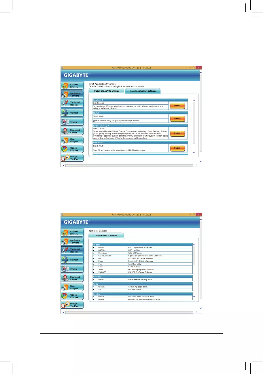
— 66 —
4-2 Application Software
This page displays all the utilities and applications that GIGABYTE develops and some free software. You
can click the Install button on the right of an item to install it.
4-3 Technical Manuals
This page provides the content descriptions for this driver disk.
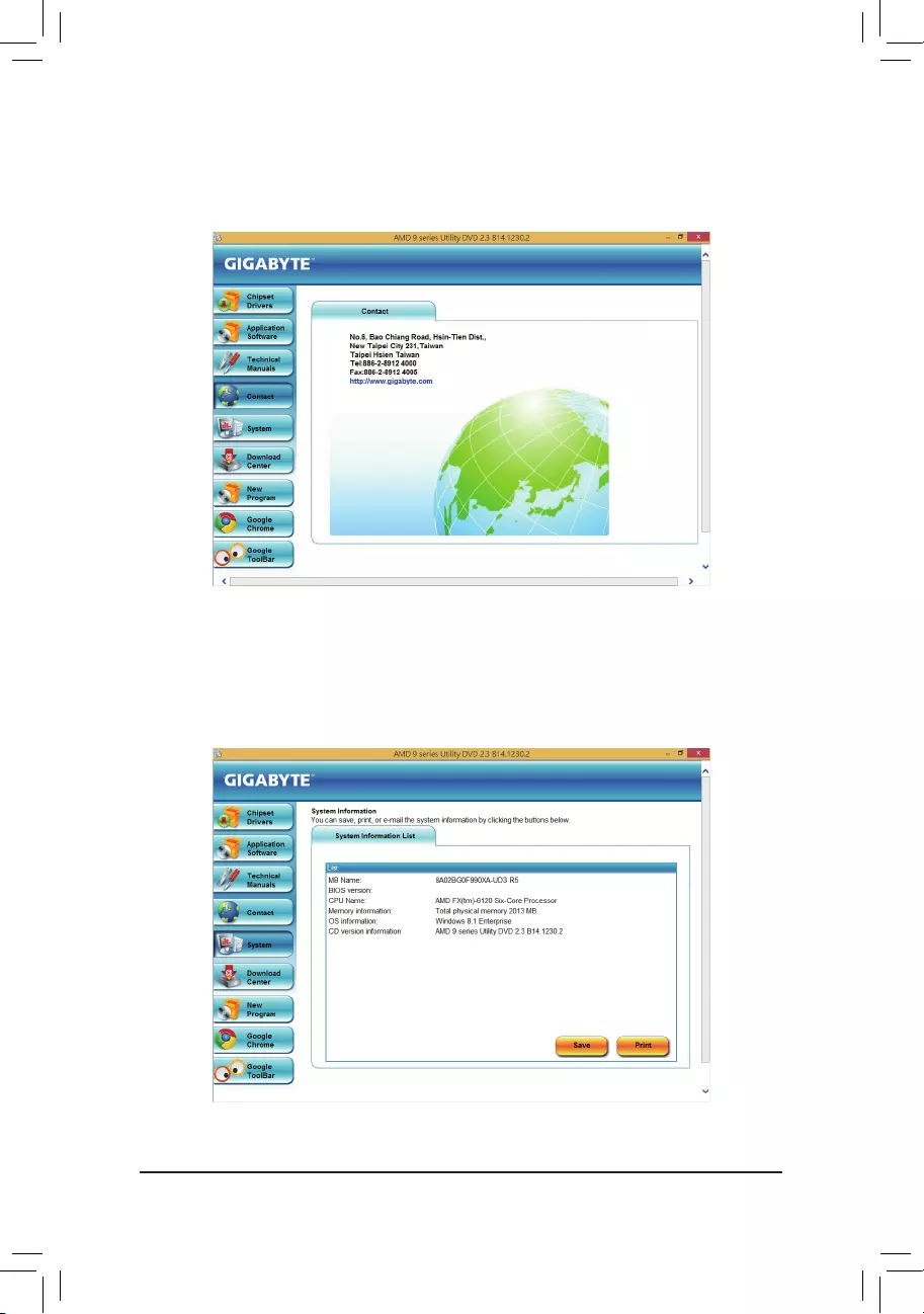
— 67 —
4-4 Contact
For the detailed contact information of the GIGABYTE Taiwan headquarter or worldwide branch ofces, click
the URL on this page to link to the GIGABYTE website.
4-5 System
This page provides the basic system information.
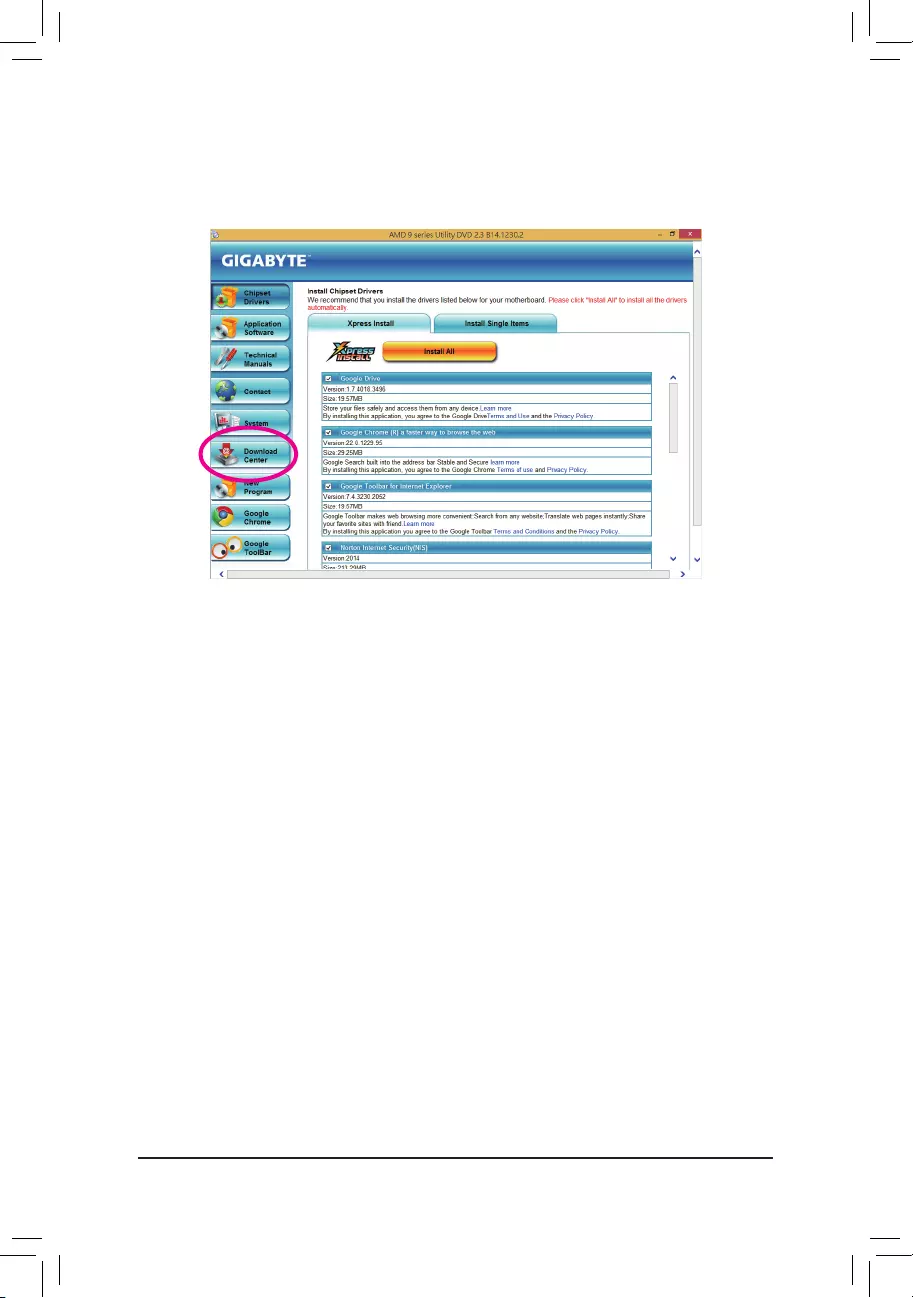
— 68 —
4-6 Download Center
To update the BIOS, drivers, or applications, click the Download Center button to link to the GIGABYTE
website. The latest version of the BIOS, drivers, or applications will be displayed.

— 69 —
5-1 BIOS Update Utilities
GIGABYTE motherboards provide two unique BIOS update tools, Q-Flash™ and @BIOS™. GIGABYTE Q-Flash
and @BIOS are easy-to-use and allow you to update the BIOS without the need to enter MS-DOS mode.
Additionally, this motherboard features the DualBIOS™ design, which enhances protection for the safety and
stability of your computer by adding one more physical BIOS chip.
What is DualBIOS™?
Motherboards that support DualBIOS have two BIOS onboard, a main BIOS and a backup BIOS. Normally, the
system works on the main BIOS. However, if the main BIOS is corrupted or damaged, the backup BIOS will
takeoveronthenextsystembootandcopytheBIOSletothemainBIOStoensurenormalsystemoperation.
For the sake of system safety, users cannot update the backup BIOS manually.
What is Q-Flash™?
With Q-Flash you can update the system BIOS without having to enter operating systems like MS-DOS or
Windowrst.EmbeddedintheBIOS,theQ-Flashtoolfreesyoufromthehasslesofgoingthroughcomplicated
BIOSashingprocess.
What is @BIOS™?
@BIOS allows you to update the system BIOS while in the Windows environment. @BIOS will download the
latestBIOSlefromthenearest@BIOSserversiteandupdatetheBIOS.
BecauseBIOSashingispotentiallyrisky,pleasedoitwithcaution.InadequateBIOSashingmay
result in system malfunction.
5-1-1 Updating the BIOS with the Q-Flash Utility
A. Before You Begin
1. FromGIGABYTE’swebsite,downloadthelatestcompressedBIOSupdatelethatmatchesyourmotherboard
model.
2. ExtracttheleandsavethenewBIOSle(e.g.990XAUD3R5.F1)toyourUSBashdrive,orharddrive.
Note:TheUSBashdriveorharddrivemustuseFAT32/16/12lesystem.
3. Restart the system. During the POST, press the <End> key to enter Q-Flash. Note: You can access Q-Flash
by either pressing the <End> key during the POST or pressing the <F8> key in BIOS Setup. However, if the
BIOSupdateleissavedtoaharddriveinRAID/AHCImodeoraharddriveattachedtoanindependent
SATA controller, use the <End> key during the POST to access Q-Flash.
Chapter 5 Unique Features
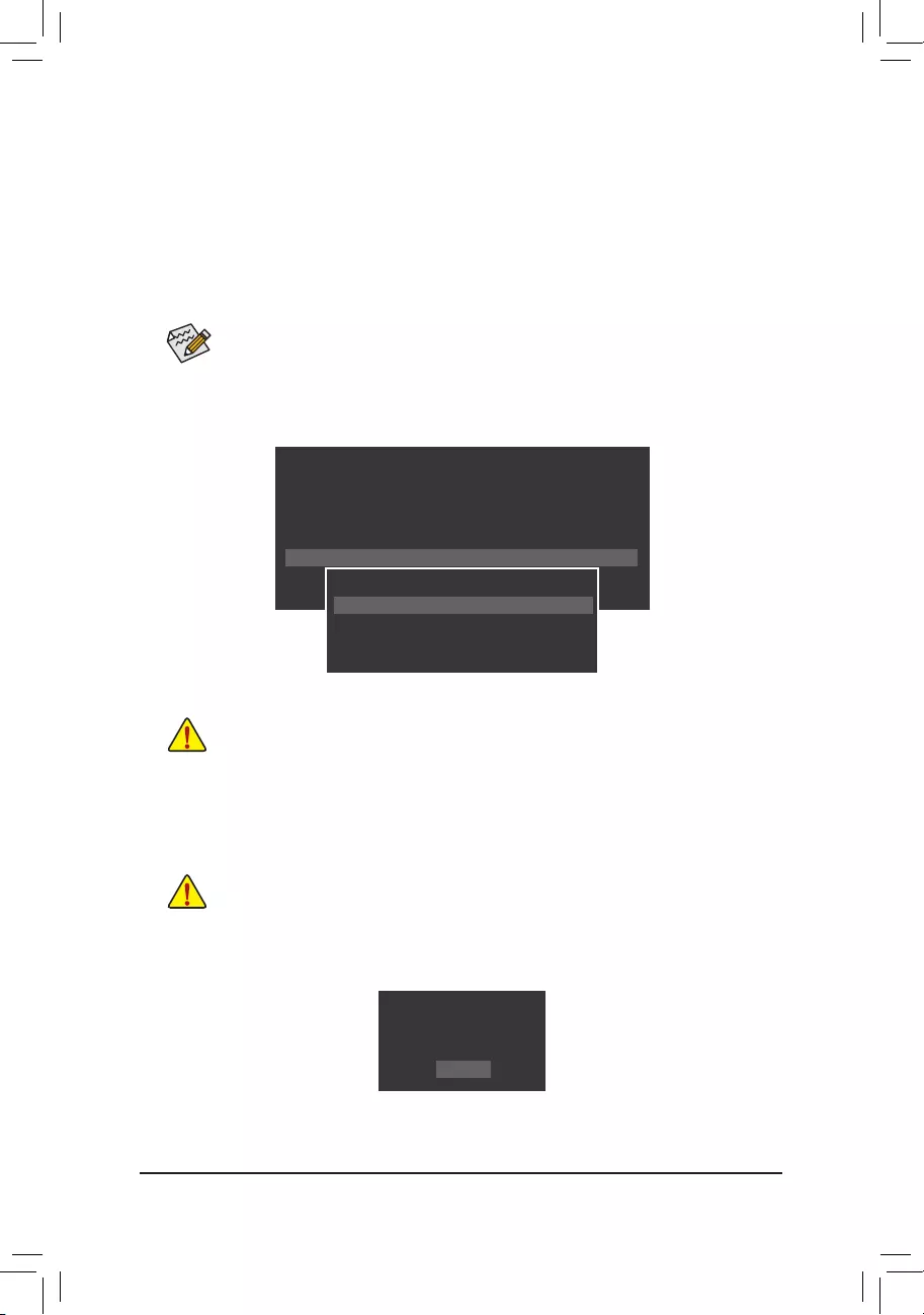
— 70 —
B. Updating the BIOS
In the main menu of Q-Flash, use the keyboard or mouse to select an item to execute. When updating the
BIOS,choosethelocationwheretheBIOSleissaved.Thefollowingprocedureassumesthatyousavethe
BIOSletoaUSBashdrive.
Step 1:
1. InserttheUSBashdrivecontainingtheBIOSleintothecomputer.InthemainmenuofQ-Flash,select
Update BIOS From Drive.
Step 2:
TheprocessofthesystemreadingtheBIOSlefromtheUSBashdriveisdisplayedonthescreen.When
the message «Are you sure to update BIOS?» appears, select Yes to begin the BIOS update. The monitor will
display the update process.
Step 3:
When the update process is complete, select Reboot to reboot the system.
2. Select USB Flash Drive.
3. SelecttheBIOSupdatele.
•The Save Main BIOS to DriveoptionallowsyoutosavethecurrentBIOSle.
•Q-FlashonlysupportsUSBashdriveorharddrivesusingFAT32/16/12lesystem.
•IftheBIOSupdateleissavedtoaharddriveinRAID/AHCImodeoraharddriveattached
to an independent SATA controller, use the <End> key during the POST to access Q-Flash.
MakesuretheBIOSupdatelematchesyourmotherboardmodel.
•Do not turn off or restart the system when the system is reading/updating the BIOS.
•DonotremovetheUSBashdriveorharddrivewhenthesystemisupdatingtheBIOS.
Q-Flash Utility v1.05
Model Name : 990XA-UD3 R5
BIOS Version : F1
BIOS Date : 1/28/2015
Flash Type/Size : MXIC 25L3206E 4MB
Update BIOS From Drive
Save BIOS to Drive
Return to BIOS setup
Select Device
USB Flash Drive
Q-Flash
BIOS update is completed.
Power off
Reboot
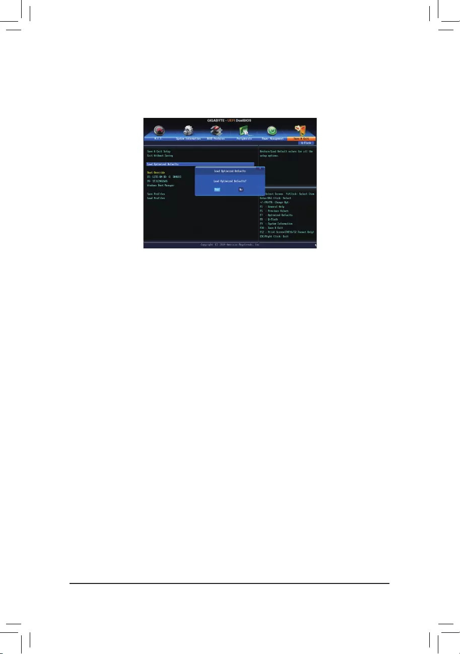
— 71 —
Step 4:
During the POST, press <Delete> to enter BIOS Setup. Select Load Optimized Defaults on the Save & Exit
screen and press <Enter> to load BIOS defaults. System will re-detect all peripheral devices after a BIOS update,
so we recommend that you reload BIOS defaults.
Step 5:
Select Save & Exit Setup and press <Enter>. And then select Yes to save settings to CMOS and exit BIOS
Setup. The procedure is complete after the system restarts.
Select Yes to load BIOS defaults
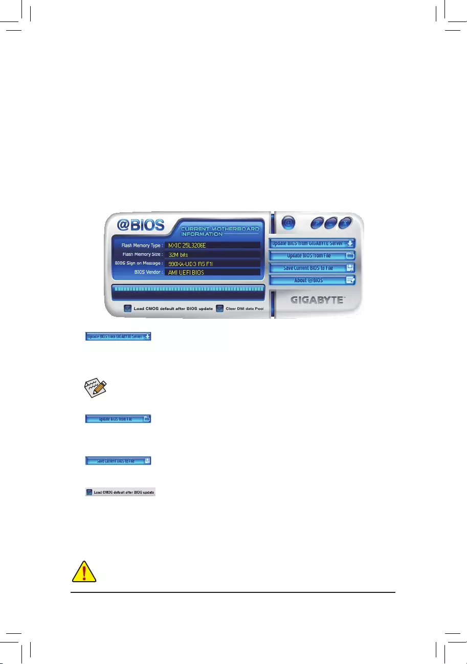
— 72 —
5-1-2 Updating the BIOS with the @BIOS Utility
A. Before You Begin
1. InWindows,closeallapplicationsandTSR(TerminateandStayResident)programs.Thishelpsprevent
unexpected failures when performing a BIOS update.
2. During the BIOS update process, ensure the Internet connection is stable and do NOT interrupt the Internet
connection(forexample,avoidapowerlossorswitchingofftheInternet).Failuretodosomayresultina
corrupted BIOS or a system that is unable to start.
3. DonotusetheG.O.M.(GIGABYTEOnlineManagement)functionwhenusing@BIOS.
4. GIGABYTE product warranty does not cover any BIOS damage or system failure resulting from an inadequate
BIOSashing.
B. Using @BIOS
MakesurethattheBIOSletobeashedmatchesyourmotherboardmodel.Updatingthe
BIOSwithanincorrectBIOSlecouldcauseyoursystemnottoboot.
1. Update the BIOS Using the Internet Update Function:
Click Update BIOS from GIGABYTE Server, select the @BIOS server site closest to your location and
thendownloadtheBIOSlethatmatchesyourmotherboardmodel.Followtheon-screeninstructionsto
complete.
2. Update the BIOS without Using the Internet Update Function:
Click Update BIOS from File,thenselectthelocationwhereyousavetheBIOSupdateleobtainedfrom
the Internet or through other source. Follow the on-screen instructions to complete.
3. Save the Current BIOS File:
Click Save Current BIOS to FiletosavethecurrentBIOSle.
4. Load BIOS Defaults after BIOS Update:
Select the Load CMOS default after BIOS update check box and then the system will automatically load
BIOS defaults after BIOS update and after the system restarts.
C. After Updating the BIOS
Restart your system after updating the BIOS.
IftheBIOS update le foryourmotherboardis not present onthe@BIOS server site, please
manuallydownloadtheBIOSupdatelefromGIGABYTE’swebsiteandfollowtheinstructionsin
«Update the BIOS without Using the Internet Update Function» below.
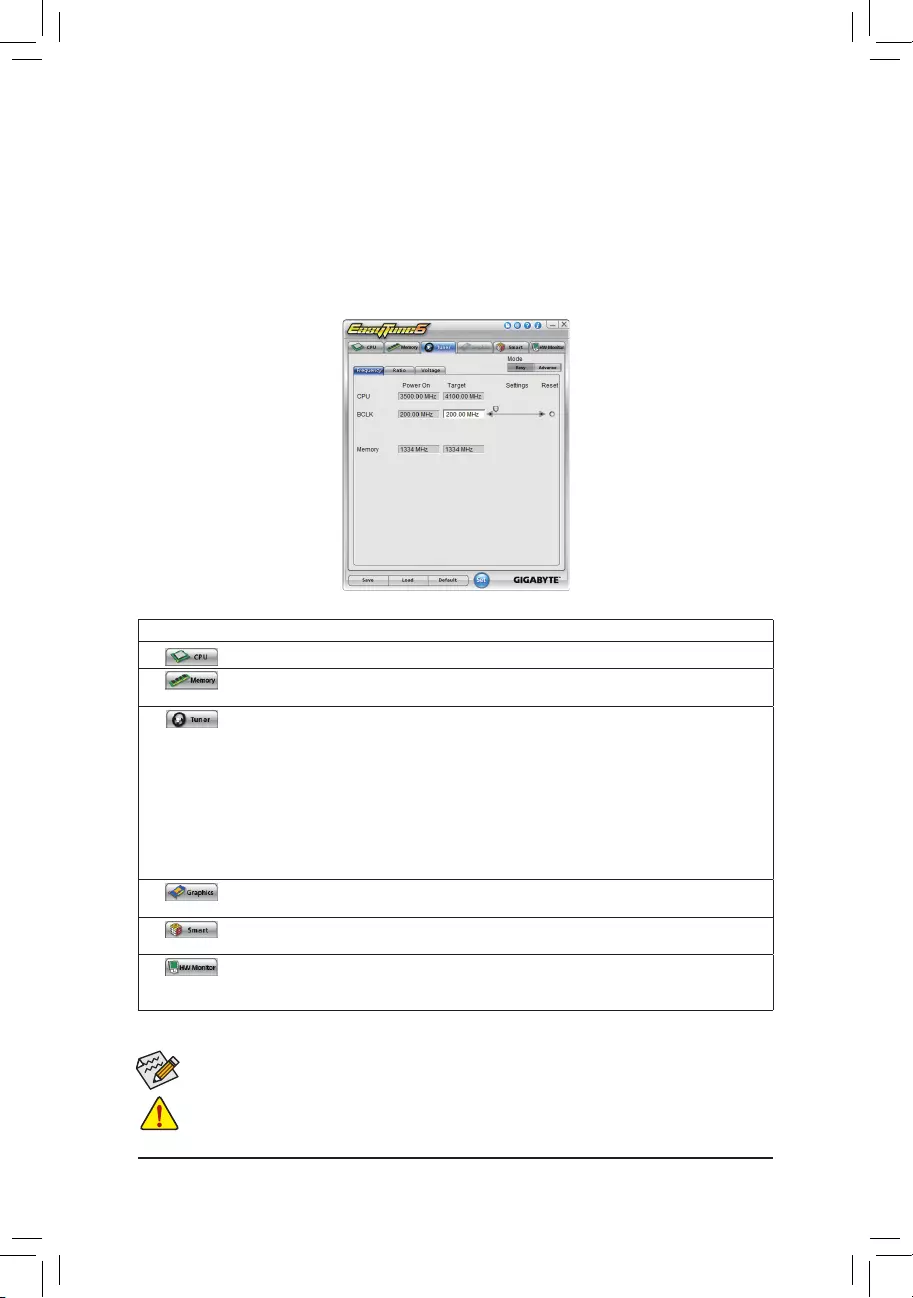
— 73 —
5-2 EasyTune 6
GIGABYTE’sEasyTune6isasimple andeasy-to-use interfacethat allowsusers tone-tune theirsystem
settings or do overclock/overvoltage in Windows environment. The user-friendly EasyTune 6 interface also
includes tabbed pages for CPU and memory information, letting users read their system-related information
without the need to install additional software.
The EasyTune 6 Interface
AvailablefunctionsinEasyTune6maydifferbymotherboardmodel.Grayed-outarea(s)indicatesthattheitemisnot
congurableorthefunctionisnotsupported.
Incorrectly doing overclock/overvoltage may result in damage to the hardware components such as CPU, chipset, and
memory and reduce the useful life of these components. Before you do the overclock/overvoltage, make sure that you
fully know each function of EasyTune 6, or system instability or other unexpected results may occur.
Tabs Information
Tab Description
The CPU tab provides information on the installed CPU and motherboard.
The Memory tabprovidesinformation ontheinstalled memorymodule(s).You canselectmemory
moduleonaspecicslottoseeitsinformation.
The Tuner tab allows you to change memory settings and voltages.
•Easy mode provides information on CPU/memory.
•Advanced mode allows you to individually change system clock settings and voltages settings
using the sliders.
•Save allowsyoutosavethecurrentsettingstoanewprole(.txtle).
•Load allowsyoutoloadprevioussettingsfromaprole.
After making changes in Easy mode/Advanced mode, be sure to click Set for these changes to
take effect or click Default to restore to default values.
The Graphics tab allows you to change the core clock and memory clock for your AMD or NVIDIA
graphics card.
The Smart tab allows you to specify a Smart Fan mode. Smart Fan Advanced mode allows the fan
speed to be changed linearly based on the temperature thresholds you set.
The HW Monitor tab allows you to monitor hardware temperature, voltage and fan speed and set
temperature/fanspeedalarm.Youcanchoosethealertsoundfromthebuzzeroruseyourownsound
le(.wavle).

— 74 —

— 75 —
Chapter 6 Appendix
6-1-1 Conguring2/4/5.1/7.1-ChannelAudio
The motherboard provides six audio jacks on the back
panel which support 2/4/5.1/7.1-channel(Note) audio.
The picture to the right shows the default audio jack
assignments.
TheintegratedHD (High Denition) audioprovides
jack retasking capability that allows the user to change
the function for each jack through the audio driver.
(Supportedfunctionsforeachjackmayvarybasedon
hardwarespecication.)
6-1 ConguringAudioInputandOutput
HighDenitionAudio(HDAudio)
HDAudioincludes multiple high quality digital-to-analog converters (DACs) andfeaturesmultistreaming
capabilitiesthatallowmultipleaudiostreams(inandout)tobesimultaneouslyprocessed.Forexample,userscan
listen to MP3 music, have an Internet chat, make a telephone call over the Internet, and etc. all at the same time.
A.ConguringSpeakers
(ThefollowinginstructionsuseWindows8.1astheexampleoperatingsystem.)
•Toinstallamicrophone,connectyourmicrophonetotheMicinjackandmanuallycongurethe
jack for microphone functionality.
•Audio signals will be present on both of the front and back panel audio connections simultaneously.
Ifyouwanttomutethebackpanelaudio(onlysupportedwhenusinganHDfrontpanelaudio
module),refertoinstructionsonthenextpage.
Center/Subwoofer
Speaker Out Line In
Rear Speaker Out
Side Speaker Out
Front Speaker Out
Mic In
Step 1:
After installing the audio driver, restart your computer.
Then switch to Windows desktop mode. The HD Audio
Manager icon will appear inthenoticationarea.
Double-click the icon to access the HD Audio Manager.
(Note) 2/4/5.1/7.1-ChannelAudioCongurations:
Refertothefollowingformulti-channelspeakercongurations.
•2-channel audio: Headphone or Line out.
•4-channel audio: Front speaker out and Side speaker out.
•5.1-channel audio: Front speaker out, Side speaker out, and Center/Subwoofer speaker out.
•7.1-channel audio: Front speaker out, Rear speaker out, Center/Subwoofer speaker out, and Side speaker out.
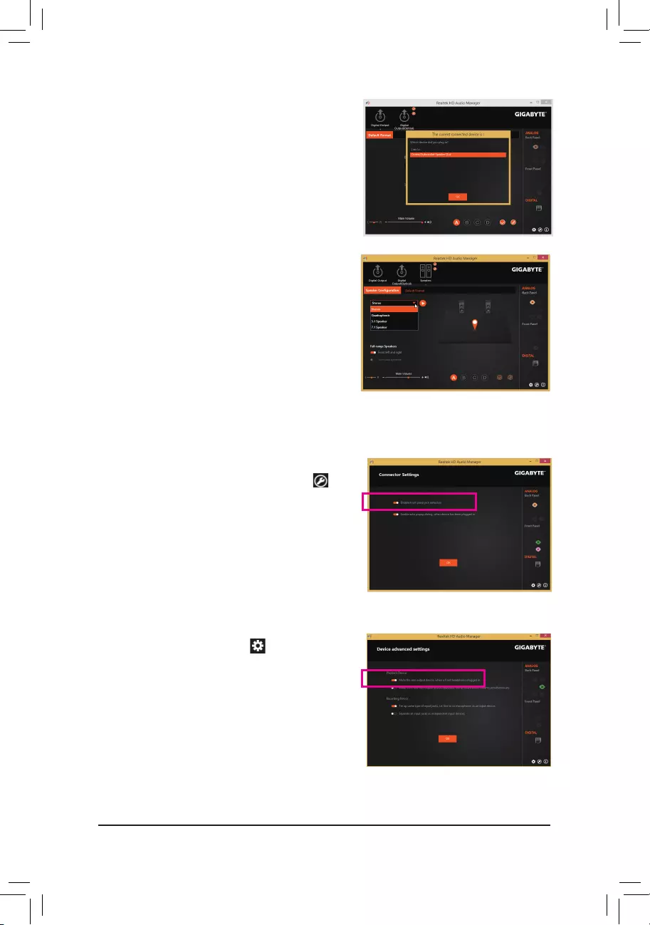
— 76 —
Step 2:
Connect an audio device to an audio jack. The The current
connected device is dialog box appears. Select the device
according to the type of device you connect. Then click OK.
Step 3:
On the Speakers screen, click the SpeakerConguration
tab. In the Speaker Configuration list, select Stereo,
Quadraphonic, 5.1 Speaker, or 7.1 Speaker according to
thetypeofspeakercongurationyouwishtosetup.Then
the speaker setup is completed.
B.ConguringSoundEffect
YoumaycongureanaudioenvironmentontheSound Effects tab.
If your chassis provides an AC’97 front panel audio module,
to activate the AC’97 functionality, click the Tool icon on
the right bottom of the screen . On the Connector Settings
dialog box, select the Disable front panel jack detection
check box. Click OK to complete.
Click Device advanced settings icon on the right bottom
of the screen to open the Device advanced settings dialog
box. Select the Mute the rear output device, when a front
headphone plugged in check box. Click OK to complete.
C. Activating an AC’97 Front Panel Audio Module
D. Muting the Back Panel Audio (For HD Audio Only)
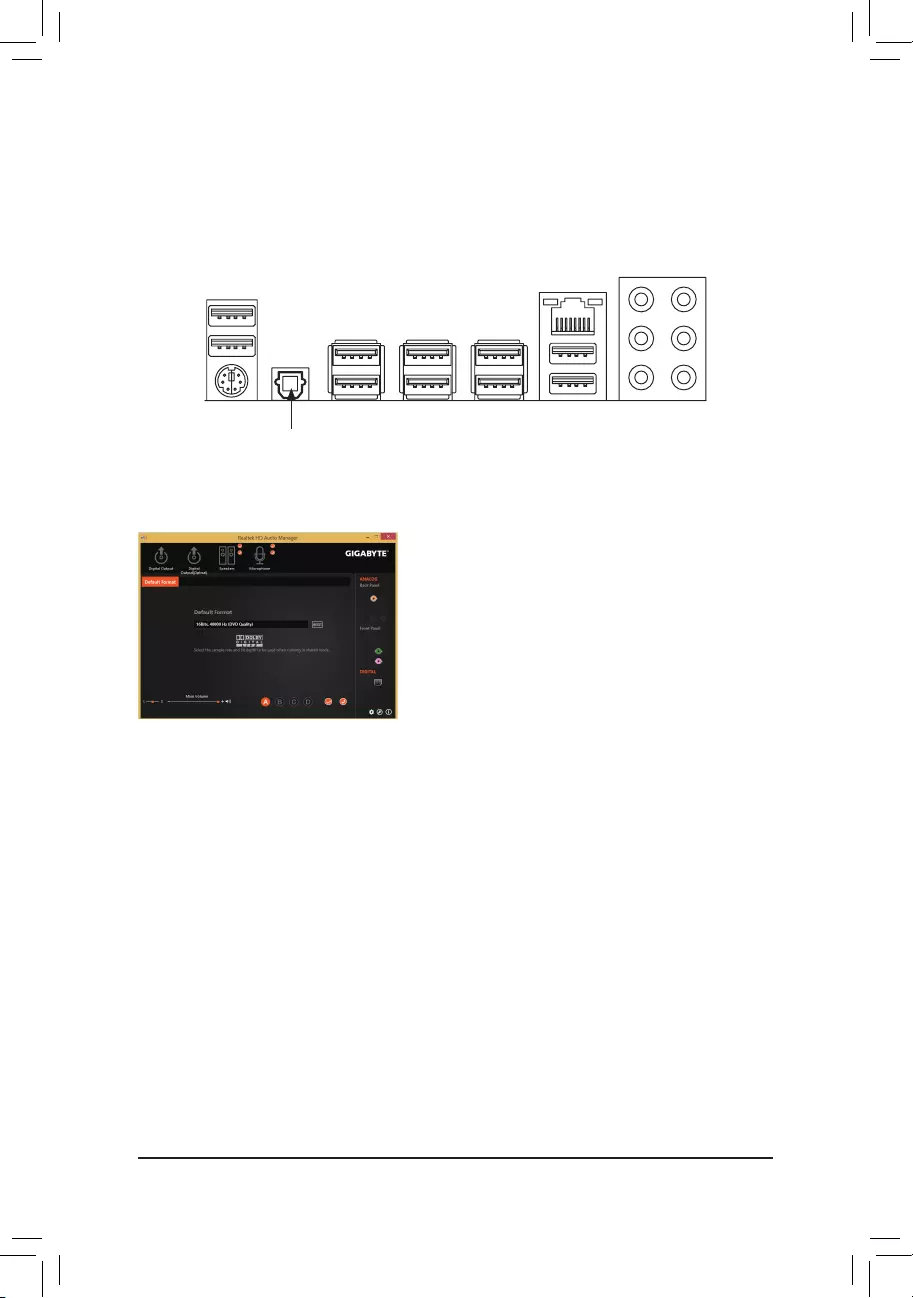
— 77 —
(Note) Enterthe Digital Output(Optical)screento congurefurthersettings ifyouuse theS/PDIFOut
connector(s)onthebackpanelfordigitalaudiooutputorentertheDigital Output screen if you use
theinternalS/PDIFOutconnector(SPDIF_O)fordigitalaudiooutput.
The S/PDIF Out jack can transmit audio signals to an external decoder for decoding to get the best audio quality.
1. Connecting a S/PDIF Out Cable:
Connect a S/PDIF optical cable to an external decoder for transmitting the S/PDIF digital audio signals.
2.ConguringS/PDIFOut:
On the Digital Output(Optical) screen (Note), click the Default Format tab and then select the sample rate and
bit depth. Click OK to complete.
Connects to a S/PDIF optical cable
6-1-2 ConguringS/PDIFOut
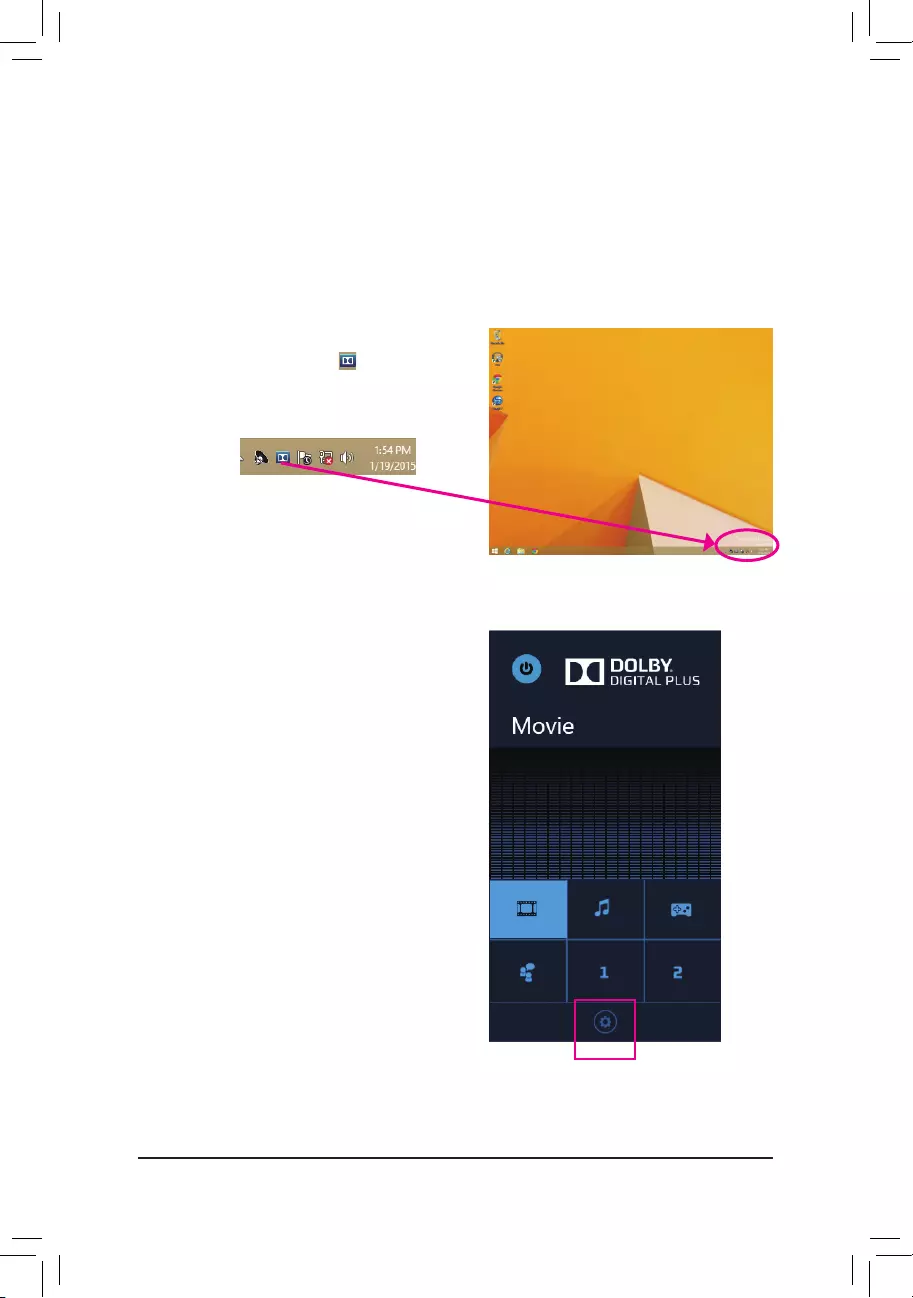
— 78 —
6-1-3 Enabling the Dolby® Home Theater® Function
Before Dolby® Home Theater®isenabled,yougetonly2-channelplaybackoutput(fromthefrontspeakers)
when playing 2-channel stereo sources. You must play 4-, 5.1-, or 7.1- channel content to get 4-, 5.1-, or 7.1-
channel audio effects. With Dolby® Home Theater® enabled, 2-channel stereo content will be transformed into
multi-channel audio, creating a virtual surround sound environment.
Step 1:
The Dolby® Home Theater® icon will appear in the
noticationarea.Click the icon to accesstheDolby®
Home Theater®.
Step 2:
Click the Customize button on the Dolby® Home
Theater® panel to open advanced settings.
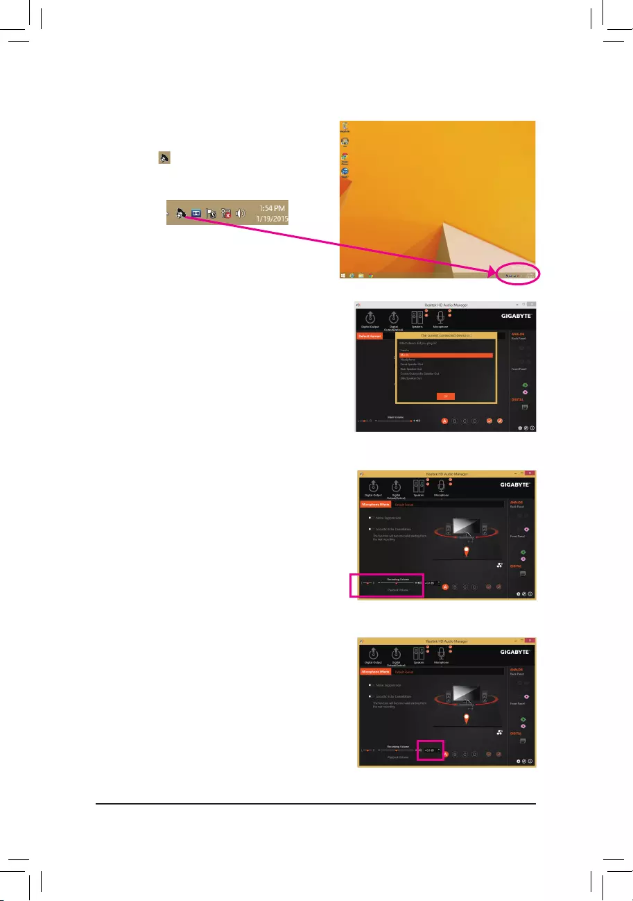
— 79 —
6-1-4 ConguringMicrophoneRecording
Step 2:
ConnectyourmicrophonetotheMicinjack(pink)onthe
backpanelortheMicinjack(pink)onthefrontpanel.
Thencongurethejackformicrophonefunctionality.
Note: The microphone functions on the front panel and
back panel cannot be used at the same time.
Step 1:
Switch to Windows desktop mode. The HD Audio
Manager icon will appear inthenoticationarea.
Double-click the icon to access the HD Audio Manager.
Step 3:
Go to the Microphone screen. Do not mute the recording
volume, or you’ll not be able to record the sound. To hear
the sound being recorded during the recording process,
do not mute the playback volume. It is recommended that
you set the volumes at a middle level.
Step 4:
To raise the recording and playback volume for the
microphone, you can set the Microphone Boost level on
the right of the Recording Volume slider.
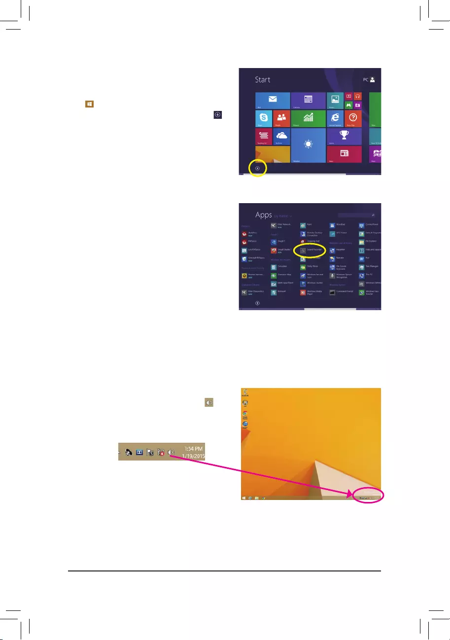
— 80 —
Step 1:
Switch to Windows desktop mode. Locate the icon
inthenoticationareaandright-clickonthisicon.Select
Recording Devices.
* Enabling Stereo Mix
If the HD Audio Manager does not display the recording device you wish to use, refer to the steps below. The
followingstepsexplainhowtoenableStereoMix(whichmaybeneededwhenyouwanttorecordsoundfrom
yourcomputer).
Step 5:
To open the Sounder Recorder, move the mouse
cursor to the bottom left corner of the screen, click the
Start icon to switch to the Startscreen(orpress
theWindowsbutton on the keyboard). Clickthe
icon on the bottom left corner of the screen to access
the Apps screen.
Step 6:
On this screen, click Sound Recorder for audio recording.
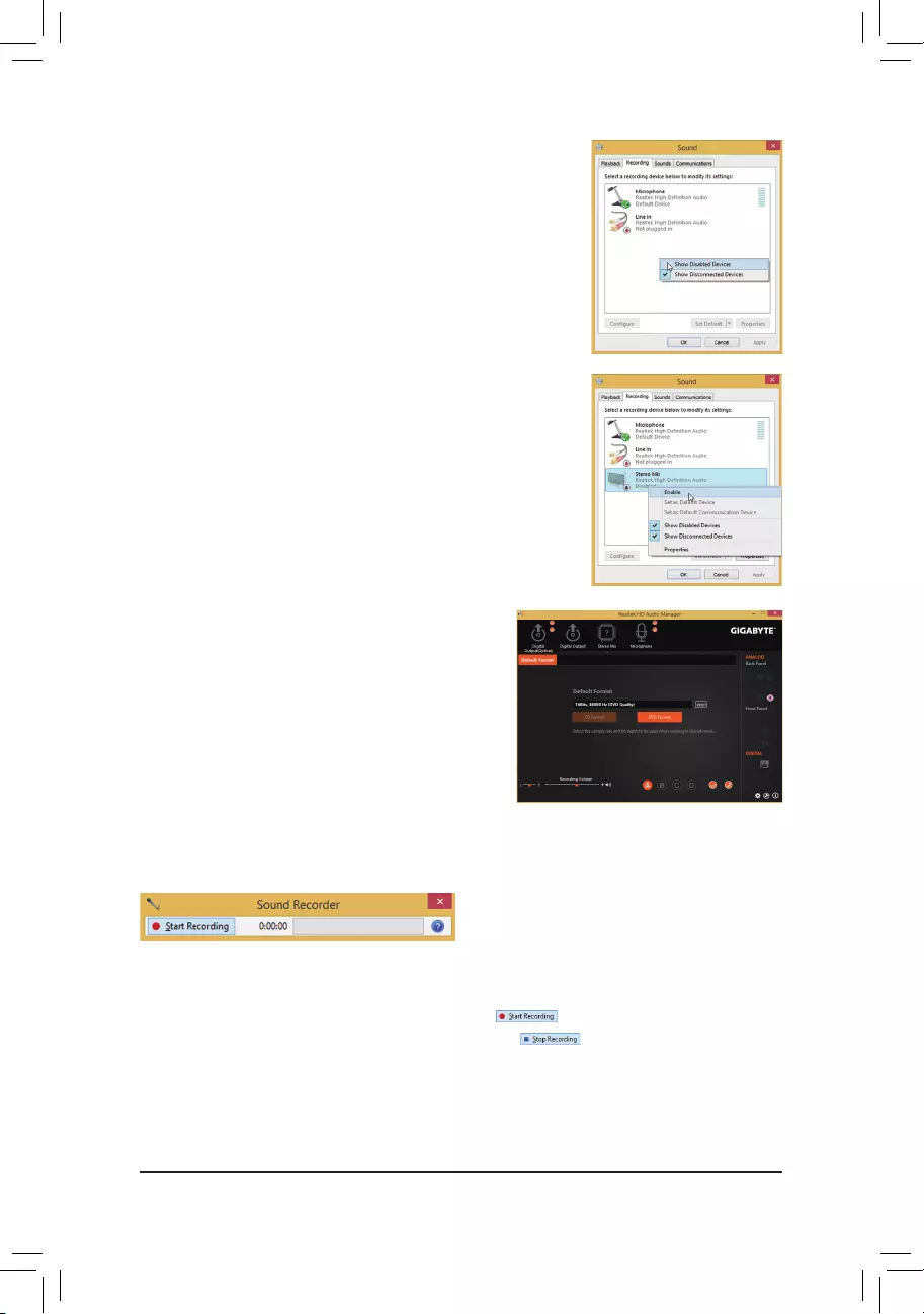
— 81 —
Step 4:
Now you can access the HD Audio Managertocongure
Stereo Mix and use Sound Recorder to record the
sound.
6-1-5 Using the Sound Recorder
A. Recording Sound
1. Makesureyouhaveconnectedthesoundinputdevice(e.g.microphone)tothecomputer.
2. To record the audio, click the Start Recording button .
3. To stop recording audio, click the Stop Recording button .
Besuretosavetherecordedaudioleuponcompletion.
B. Playing the Recorded Sound
Youcanplayyourrecordinginadigitalmediaplayerprogramthatsupportsyouraudioleformat.
Step 2:
On the Recording tab, right-click on an empty space and
select Show Disabled Devices.
Step 3:
When the Stereo Mix item appears, right-click on this
item and select Enable. Then set it as the default device.

— 82 —
6-2 Troubleshooting
6-2-1 Frequently Asked Questions
To read more FAQs for your motherboard, please go to the Support & Downloads\FAQ page on GIGABYTE’s
website.
Q: Why is the light of my keyboard/optical mouse still on after the computer shuts down?
A: Some motherboards provide a small amount of standby power after the computer shuts down and that’s why the light is
still on.
Q: How do I clear the CMOS values?
A: FormotherboardsthathaveaClearCMOSbutton,pressthisbuttontocleartheCMOSvalues(beforedoingthis,
pleaseturnoffthecomputerandunplugthepowercord).FormotherboardsthathaveaClearCMOSjumper,refertothe
instructions in Chapter 1 to short the jumper to clear the CMOS values. If your board doesn’t have this jumper/button,
refer to the instructions on the motherboard battery in Chapter 1. You can temporarily remove the battery from the battery
holder to stop supplying power to the CMOS, which will clear the CMOS values after about one minute.
Q: Why do I still get a weak sound even though I have turned my speaker to the maximum volume?
A: Makesureyourspeakerisequippedwithaninternalamplier.Ifnot,tryaspeakerwithpower/amplier.
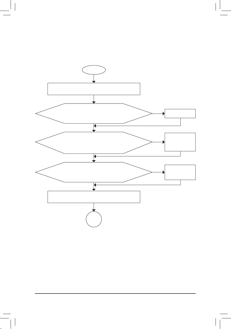
— 83 —
6-2-2 Troubleshooting Procedure
If you encounter any troubles during system startup, follow the troubleshooting procedure below to solve the
problem.
START
A
Turn off the power. Remove all peripherals, connecting cables, and
power cord etc.
Isolate the short circuit.
Secure the CPU cooler
on the CPU. Connect the
CPU cooler power cable
to the motherboard.
Correctly insert the
memory into the memory
socket.
(Continued…)
Yes
Theproblemisveriedandsolved.
Theproblemisveriedandsolved.
Theproblemisveriedandsolved.
No
No
No
Yes
Yes
Insert the graphics card. Connect the ATX main power cable and the
12V power cable. Turn on the power to start the computer.
Make sure the motherboard does not short-circuit with the chassis or
other metal objects.
Check if the CPU cooler is attached to the CPU securely. Is the
powerconnectoroftheCPUcoolerconnectedtotheCPU_FAN
header properly?
Check if the memory is installed properly on the memory slot.
Make sure the graphics card is securely seated in the
expansionslotandpowerconnectorsarermlyattached.
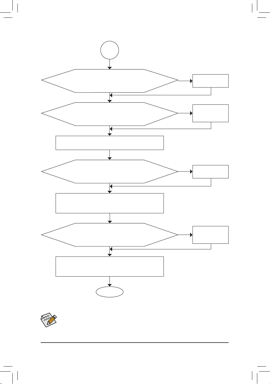
— 84 —
If the procedure above is unable to solve your problem, contact the place of purchase or local dealer
for help. Or go to the Support & Downloads\Technical Support page to submit your question. Our
customer service staff will reply you as soon as possible.
The power supply, CPU or
CPU socket might fail.
The keyboard or keyboard
connector might fail.
END
A
Turn off the computer. Plug in the keyboard and mouse and restart
the computer.
The graphics card,
expansion slot, or monitor
might fail.
The hard drive, connector,
or cable might fail.
No
Theproblemisveriedandsolved.
Theproblemisveriedandsolved.
Theproblemisveriedandsolved.
No
No
Yes
Yes
Yes
Reinstall the operating system. Reinstall other devices one by one
(installonedeviceatonetimeandthenbootthesystemtoseeifthe
deviceworkssuccessfully).
Press<Delete>toenterBIOSSetup.Select«LoadOptimized
Defaults.» Select «Save & Exit Setup» to save changes and exit BIOS
Setup.
Check if there is display on your monitor.
When the computer is turned on, is the CPU cooler running?
Check if the keyboard is working properly.
No
Theproblemisveriedandsolved.
Yes
Turn offthe computerandconnectthehard drive(s). Checkifthe
system can boot successfully.
— 85 —
Regulatory Statements
Regulatory Notices
This document must not be copied without our written permission, and the contents there of must not be imparted
toathirdpartynorbeusedforanyunauthorizedpurpose.Contraventionwillbeprosecuted.Webelievethatthe
information contained herein was accurate in all respects at the time of printing. GIGABYTE cannot, however,
assume any responsibility for errors or omissions in this text. Also note that the information in this document is
subject to change without notice and should not be construed as a commitment by GIGABYTE.
Our Commitment to Preserving the Environment
Inadditiontohigh-efciency performance, all GIGABYTE motherboardsfulllEuropean Union regulations
forRoHS(RestrictionofCertainHazardousSubstancesinElectricalandElectronicEquipment)andWEEE
(WasteElectricalandElectronicEquipment)environmentaldirectives,aswellasmostmajorworldwidesafety
requirements.Topreventreleasesofharmfulsubstancesintotheenvironmentandtomaximizetheuseofour
natural resources, GIGABYTE provides the following information on how you can responsibly recycle or reuse
most of the materials in your «end of life» product.
Restriction of Hazardous Substances (RoHS) Directive Statement
GIGABYTEproductshavenotintendedtoaddandsafefromhazardoussubstances(Cd,Pb,Hg,Cr+6,PBDE
andPBB).ThepartsandcomponentshavebeencarefullyselectedtomeetRoHSrequirement.Moreover,weat
GIGABYTE are continuing our efforts to develop products that do not use internationally banned toxic chemicals.
Waste Electrical & Electronic Equipment (WEEE) Directive Statement
GIGABYTEwillfulllthenationallawsasinterpretedfromthe2002/96/ECWEEE(WasteElectricalandElectronic
Equipment)directive.TheWEEEDirectivespeciesthetreatment,collection,recyclinganddisposalofelectric
and electronic devices and their components. Under the Directive, used equipment must be marked, collected
separately, and disposed of properly.
WEEE Symbol Statement
The symbol shown below is on the product or on its packaging, which indicates that this product
must not be disposed of with other waste. Instead, the device should be taken to the waste collection
centers for activation of the treatment, collection, recycling and disposal procedure. The separate
collection and recycling of your waste equipment at the time of disposal will help to conserve natural
resources and ensure that it is recycled in a manner that protects human health and the environment.
For more information about where you can drop off your waste equipment for recycling, please contact your
localgovernmentofce,yourhouseholdwastedisposalserviceorwhereyoupurchasedtheproductfordetails
of environmentally safe recycling.
When your electrical or electronic equipment is no longer useful to you, «take it back» to your local or regional
waste collection administration for recycling.
If you need further assistance in recycling, reusing in your «end of life» product, you may contact us at the
Customer Care number listed in your product’s user’s manual and we will be glad to help you with your effort.
Finally, we suggest that you practice other environmentally friendly actions by understanding and using the
energy-savingfeaturesofthisproduct(whereapplicable),recyclingtheinnerandouterpackaging(including
shippingcontainers)thisproductwasdeliveredin,andbydisposingoforrecyclingusedbatteriesproperly.
With your help, we can reduce the amount of natural resources needed to produce electrical and electronic
equipment,minimizetheuseoflandllsforthedisposalof«endoflife»products,andgenerallyimproveour
qualityoflifebyensuringthatpotentiallyhazardoussubstancesarenotreleasedintotheenvironmentandare
disposed of properly.

— 86 —
FCC Notice (U.S.A. Only)
This equipment has been tested and found to comply with the limits for a Class B digital device, pursuant to Part
15 of the FCC Rules. These limits are designed to provide reasonable protection against harmful interference
in a residential installation. This equipment generates, uses, and can radiate radio frequency energy and, if not
installed and used in accordance with the instructions, may cause harmful interference to radio communications.
However, there is no guarantee that interference will not occur in a particular installation. If this equipment does
cause harmful interference to radio or television reception, which can be determined by turning the equipment
off and on, the user is encouraged to try to correct the interference by one or more of the following measures:
Reorient or relocate the receiving antenna.
Increase the separation between the equipment and receiver.
Connect the equipment into an outlet on a circuit different from that to which the receiver is connected.
Consult a dealer or experienced TV/radio technician for help.
Canada, Industry Canada (IC) Notices / Canada, avis d’Industry Canada (IC)
This Class B digital apparatus complies with Canadian ICES-003 and RSS-210.
Operationissubjecttothefollowingtwoconditions:(1)thisdevicemaynotcauseinterference,and(2)this
device must accept any interference, including interference that may cause undesired operation of the device.
Cet appareil numérique de classe B est conforme aux normes canadiennes ICES-003 et RSS-210.
Sonfonctionnementest soumis aux deux conditionssuivantes: (1) cet appareil nedoitpas causer
d’interférenceet(2)cetappareildoitacceptertouteinterférence,notammentlesinterférencesquipeuvent
affecter son fonctionnement.

— 87 —
Contact Us
•GIGA-BYTE TECHNOLOGY CO., LTD.
Address: No.6, Bao Chiang Road, Hsin-Tien Dist.,
New Taipei City 231,Taiwan
TEL: +886-2-8912-4000
FAX: +886-2-8912-4005
Tech.andNon-Tech.Support(Sales/Marketing):
http://esupport.gigabyte.com
WEBaddress(English):http://www.gigabyte.com
WEBaddress(Chinese):http://www.gigabyte.tw
•G.B.T. INC. — U.S.A.
TEL: +1-626-854-9338
FAX: +1-626-854-9326
Tech. Support: http://esupport.gigabyte.com
Warranty Info: http://rma.gigabyte.us
Web address: http://www.gigabyte.us
•G.B.T. INC (USA) — Mexico
Tel:+1-626-854-9338x215(Soportedehablahispano)
FAX: +1-626-854-9326
Correo: soporte@gigabyte-usa.com
Tech. Support: http://rma.gigabyte.us
Web address: http://latam.giga-byte.com
•Giga-Byte SINGAPORE PTE. LTD. — Singapore
WEB address : http://www.gigabyte.sg
•Thailand
WEB address : http://th.giga-byte.com
•Vietnam
WEB address : http://www.gigabyte.vn
•NINGBO G.B.T. TECH. TRADING CO., LTD. — China
WEB address : http://www.gigabyte.cn
Shanghai
TEL: +86-21-63400912
FAX: +86-21-63400682
Beijing
TEL: +86-10-62102838
FAX: +86-10-62102848
Wuhan
TEL: +86-27-87685981
FAX: +86-27-87579461
GuangZhou
TEL: +86-20-87540700
FAX: +86-20-87544306
Chengdu
TEL: +86-28-85483135
FAX: +86-28-85256822
Xian
TEL: +86-29-85531943
FAX: +86-29-85510930
Shenyang
TEL: +86-24-83992342
FAX: +86-24-83992102
•GIGABYTE TECHNOLOGY (INDIA) LIMITED — India
WEB address : http://www.gigabyte.in
•Saudi Arabia
WEB address : http://www.gigabyte.com.sa
•Gigabyte Technology Pty. Ltd. — Australia
WEB address : http://www.gigabyte.com.au
— 88 —
•G.B.T. TECHNOLOGY TRADING GMBH — Germany
WEB address : http://www.gigabyte.de
•G.B.T. TECH. CO., LTD. — U.K.
WEB address : http://www.giga-byte.co.uk
•Giga-Byte Technology B.V. — The Netherlands
WEB address : http://www.giga-byte.nl
•GIGABYTE TECHNOLOGY FRANCE — France
WEB address : http://www.gigabyte.fr
•Sweden
WEB address : http://www.gigabyte.se
•Italy
WEB address : http://www.giga-byte.it
•Spain
WEB address : http://www.giga-byte.es
•Greece
WEB address : http://www.gigabyte.com.gr
•Czech Republic
WEBaddress:http://www.gigabyte.cz
•Hungary
WEB address : http://www.giga-byte.hu
•Turkey
WEB address : http://www.gigabyte.com.tr
•Russia
WEB address : http://www.gigabyte.ru
•Poland
WEB address : http://www.gigabyte.pl
•Ukraine
WEB address : http://www.gigabyte.ua
•Romania
WEB address : http://www.gigabyte.com.ro
•Serbia
WEB address : http://www.gigabyte.co.rs
•Kazakhstan
WEBaddress:http://www.gigabyte.kz
You may go to the GIGABYTE website, select your language
in the language list on the top right corner of the website.
•GIGABYTE eSupport
Tosubmitatechnicalornon-technical(Sales/Marketing)question,pleaselinkto:
http://esupport.gigabyte.com