
Manual
View the manual for the Gigabyte GA-Z77-D3H here, for free. This user manual comes under the category motherboards and has been rated by 1 people with an average of a 7. This manual is available in the following languages: English. Do you have a question about the Gigabyte GA-Z77-D3H?
Ask your question here
Gigabyte GA-Z77-D3H specifications
Below you will find the product specifications and the manual specifications of the Gigabyte GA-Z77-D3H.
Maximum internal memory
32 GB
Processor manufacturer
Intel
Motherboard form factor
ATX
Supported storage drive interfaces
SATA II, SATA III
General
| Brand | Gigabyte |
| Model | GA-Z77-D3H | GA-Z77-D3H |
| Product | motherboard |
| EAN | 0230494843122, 0818313014412, 4719331806156, 5053313851628, 8183130144126, 9154401348740 |
| Language | English |
| Filetype | User manual (PDF), Installation Guide (PDF) |
Memory
| Maximum internal memory | 32 GB |
| Number of memory slots | 4 |
| Memory voltage | 1.5 V |
| Supported memory module capacities | 16GB, 1GB, 2GB, 4GB, 8GB |
| Supported memory clock speeds | 1066,1333,1600 MHz |
| Supported memory types | DDR3-SDRAM |
| Memory channels | Dual-channel |
| Memory slots type | DIMM |
| Unbuffered memory | Yes |
Processor
| Processor manufacturer | Intel |
| Processor socket | LGA 1155 (Socket H2) |
| Compatible processor series | Intel Core i3, Intel Core i5, Intel Core i7 |
| Maximum number of SMP processors | 1 |
| System bus rate | 5 GT/s |
Internal I/O
| USB 2.0 connectors | 3 |
| USB 3.2 Gen 1 (3.1 Gen 1) connectors | 1 |
| S/PDIF out connector | Yes |
| CPU fan connector | Yes |
| ATX Power connector (24-pin) | Yes |
| Number of EATX power connectors | 1 |
| Chassis intrusion connector | Yes |
| Number of chassis fan connectors | 3 |
| Number of Parallel ATA connectors | 0 |
| Front panel audio connector | Yes |
| TPM connector | Yes |
| Number of SATA II connectors | 4 |
| Number of SATA III connectors | 2 |
Rear panel I/O ports
| USB 2.0 ports quantity | 4 |
| USB 3.2 Gen 1 (3.1 Gen 1) Type-A ports quantity | 4 |
| PS/2 ports quantity | 1 |
| Firewire (IEEE 1394) ports | 0 |
| Ethernet LAN (RJ-45) ports | 1 |
| Headphone outputs | 5 |
| Microphone in | Yes |
| S/PDIF out port | Yes |
| VGA (D-Sub) ports quantity | 1 |
| eSATA ports quantity | 0 |
| DVI-D ports quantity | 1 |
| HDMI ports quantity | 1 |
Features
| Motherboard form factor | ATX |
| Motherboard chipset family | Intel |
| Motherboard chipset | — |
| Component for | PC |
| Cooling type | Passive |
| PC health monitoring | CPU, FAN, Temperature |
| Audio chip | VIA VT2021 |
| Audio output channels | 7.1 channels |
| Compatible operating systems | Windows 7/XP |
| Power source type | ATX |
Storage controllers
| Supported storage drive interfaces | SATA II, SATA III |
| RAID levels | 0, 1,5, 10 |
Packaging content
| Cables included | SATA |
| Drivers included | Yes |
Expansion slots
| PCI Express x4 slots | 1 |
| PCI Express x16 slots | 1 |
| PCI slots | 2 |
| PCI Express x1 slots | 3 |
| PCI Express slots version | 2.0, 3.0 |
| PCI Express configurations | 1×16+1×4 |
Weight & dimensions
Graphics
| Maximum graphics card memory | 1696 MB |
| Graphics card | HD Graphics |
| HDCP | Yes |
| On-board graphics card | Yes |
| Graphics card family | Intel |
| OpenGL version | 3.2 |
| DirectX version | 11 |
| Parallel processing technology support | 2-Way CrossFireX, LucidLogix Virtu |
| Discrete graphics support | Yes |
Other features
| Dual Link DVI | Yes |
| Controller interface type | Intel Z77 |
| Quick installation guide | Yes |
Network
| Networking features | 10/100/1000 Mbit/sec |
| Bluetooth | No |
| LAN controller | — |
| Wake-on-LAN ready | Yes |
| Ethernet interface type | Gigabit Ethernet |
| Wi-Fi standards | Not supported |
| Ethernet LAN | Yes |
| Wi-Fi | No |
BIOS
| BIOS type | EFI AMI |
| BIOS memory size | 64 Mbit |
| ACPI version | 2.0a |
| Clear CMOS jumper | Yes |
Processor special features
| Processor with Intel Graphics Technology required | Yes |
show more
Frequently asked questions
Can’t find the answer to your question in the manual? You may find the answer to your question in the FAQs about the Gigabyte GA-Z77-D3H below.
What is the width of the Gigabyte GA-Z77-D3H?
The Gigabyte GA-Z77-D3H has a width of 305 mm.
What is the depth of the Gigabyte GA-Z77-D3H?
The Gigabyte GA-Z77-D3H has a depth of 244 mm.
Is the manual of the Gigabyte GA-Z77-D3H available in English?
Yes, the manual of the Gigabyte GA-Z77-D3H is available in English .
Is your question not listed? Ask your question here

GA-Z77-D3H
GA-H77-D3H-MVP
GA-H77-D3H
User’s Manual
Rev. 1002
12M E-Z77D3H-1002R
Motherboard
Feb. 8, 2012
Feb. 8, 2012
Motherboard
GA-Z77-D3H/GA-H77-D3H-MVP/GA-H77-D3H
GA-Z77-D3H/
GA-H77-D3H-MVP/
GA-H77-D3H
Copyright
© 2012 GIGA-BYTE TECHNOLOGY CO., LTD. All rights reserved.
The trademarks mentioned in this manual are legally registered to their respective owners.
Disclaimer
Information in this manual is protected by copyright laws and is the property of GIGABYTE.
Changes to the specications and features in this manual may be made by GIGABYTE
without prior notice. No part of this manual may be reproduced, copied, translated, transmit-
ted, orpublished in any form or by any means without GIGABYTE’s prior written permission.
Documentation Classications
In order to assist in the use of this product, GIGABYTE provides the following types of
documentations:
For quick set-up of the product, read the Quick Installation Guide included with the product.
For detailed product information, carefully read the User’s Manual.
For product-related information, check on our website at: http://www.gigabyte.com
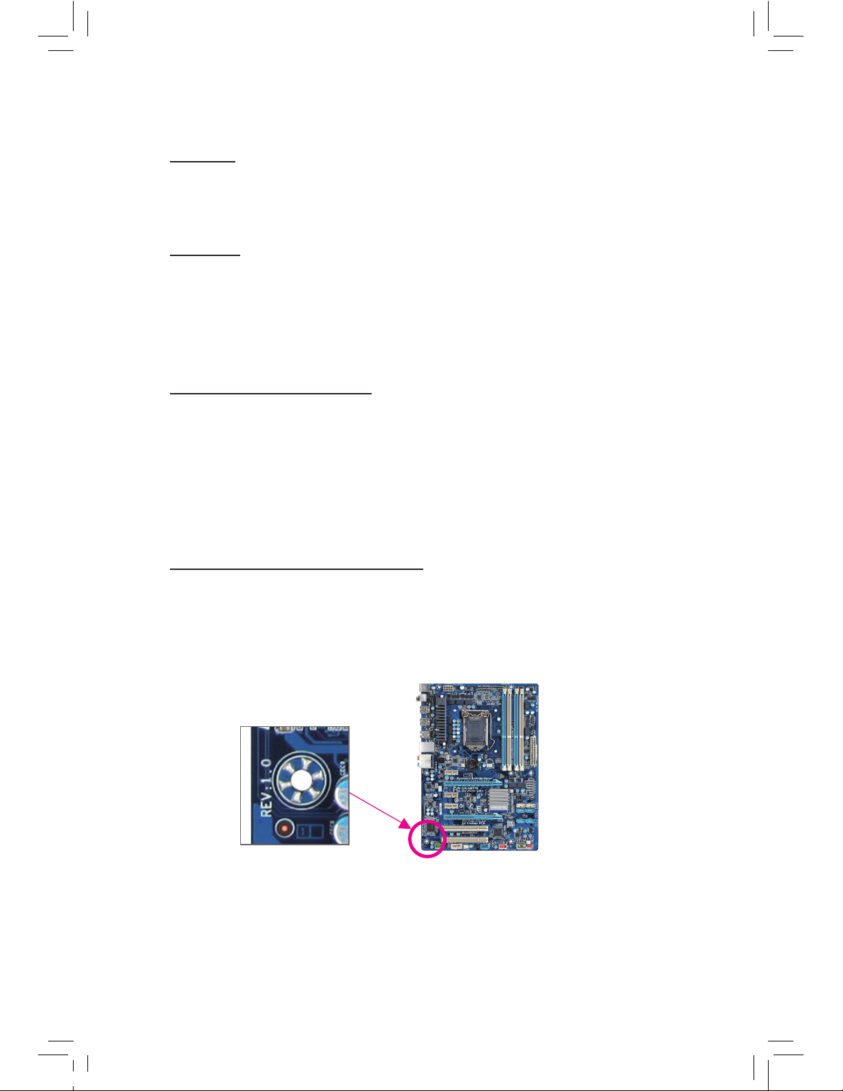
Identifying Your Motherboard Revision
The revision number on your motherboard looks like this: «REV: X.X.» For example, «REV:
1.0″ means the revision of the motherboard is 1.0. Check your motherboard revision before
updating motherboard BIOS, drivers, or when looking for technical information.
Example:

— 4 —
Table of Contents
Box Contents …………………………………………………………………………………………………….6
Optional Items …………………………………………………………………………………………………..6
GA-Z77-D3H/GA-H77-D3H-MVP/GA-H77-D3H Motherboard Layout
………………………7
GA-Z77-D3H/GA-H77-D3H-MVP/GA-H77-D3H Motherboard Block Diagram ……………8
Chapter 1 Hardware Installation ………………………………………………………………………….9
1-1 Installation Precautions ……………………………………………………………………….. 9
1-2 Product Specications ……………………………………………………………………….. 10
1-3 Installing the CPU and CPU Cooler……………………………………………………… 13
1-3-1 Installing the CPU ……………………………………………………………………………………..13
1-3-2 Installing the CPU Cooler …………………………………………………………………………..15
1-4 Installing the Memory ………………………………………………………………………… 16
1-4-1 Dual Channel Memory Conguration ………………………………………………………………16
1-4-2 Installing a Memory ……………………………………………………………………………………17
1-5 Installing an Expansion Card ………………………………………………………………. 18
1-6 Back Panel Connectors ……………………………………………………………………… 19
1-7 Internal Connectors …………………………………………………………………………… 21
Chapter 2 BIOS Setup ……………………………………………………………………………………..31
2-1 Startup Screen ………………………………………………………………………………….. 32
2-2 The Main Menu …………………………………………………………………………………. 33
2-3 M.I.T. ………………………………………………………………………………………………..35
2-4 System …………………………………………………………………………………………….. 45
2-5 BIOS Features …………………………………………………………………………………..46
2-6 Peripherals ……………………………………………………………………………………….. 48
2-7 Power Management …………………………………………………………………………… 52
2-8 Save & Exit ………………………………………………………………………………………. 54

— 5 —
Chapter 3 Drivers Installation ……………………………………………………………………………55
3-1 Installing Chipset Drivers ……………………………………………………………………. 55
3-2 Application Software …………………………………………………………………………..56
3-3 Technical Manuals …………………………………………………………………………….. 56
3-4 Contact…………………………………………………………………………………………….. 57
3-5 System …………………………………………………………………………………………….. 57
3-6 Download Center ………………………………………………………………………………. 58
3-7 New Program ……………………………………………………………………………………. 58
Chapter 4 Unique Features ……………………………………………………………………………….59
4-1 Xpress Recovery2 ……………………………………………………………………………… 59
4-2 BIOS Update Utilities …………………………………………………………………………. 62
4-2-1 Updating the BIOS with the Q-Flash Utility …………………………………………………..62
4-2-2 Updating the BIOS with the @BIOS Utility ………………………………………………….. 65
4-3 EasyTune 6 ………………………………………………………………………………………. 66
4-4 Q-Share ……………………………………………………………………………………………67
4-5 eXtreme Hard Drive (X.H.D) ……………………………………………………………….. 68
4-6 Auto Green ………………………………………………………………………………………..69
4-7 Intel Rapid Start Technology ………………………………………………………………. 70
4-8 Intel Smart Connect Technology …………………………………………………………. 72
4-9 Intel Smart Response ………………………………………………………………………… 74
Chapter 5 Appendix …………………………………………………………………………………………77
5-1 Conguring SATA Hard Drive(s) ………………………………………………………….. 77
5-1-1 Conguring SATA Controllers ……………………………………………………………………..77
5-1-2 Installing the SATA RAID/AHCI Driver and Operating System ………………………. 85
5-2 Conguring Audio Input and Output …………………………………………………….. 90
5-2-1 Conguring 2/4/5.1/7.1-Channel Audio ……………………………………………………….. 90
5-2-2 Conguring S/PDIF Out ……………………………………………………………………………..92
5-2-3 Conguring Microphone Recording ……………………………………………………………..93
5-2-4 Using the Sound Recorder ……………………………………………………………………….. 95
5-3 Troubleshooting ………………………………………………………………………………… 96
5-3-1 Frequently Asked Questions …………………………………………………………………….. 96
5-3-2 Troubleshooting Procedure ………………………………………………………………………..97
5-3-3 Regulatory Statements …………………………………………………………………………….. 99
— 6 —
Optional Items
2-port USB 2.0 bracket (Part No. 12CR1-1UB030-5*R)
2-port SATA power cable (Part No. 12CF1-2SERPW-0*R)
COM port cable (Part No. 12CF1-1CM001-3*R)
3.5″ Front Panel with 2 USB 3.0/2.0 ports (Part No. 12CR1-FPX582-0*R)
The box contents above are for reference only and the actual items shall depend on the product package you obtain.
The box contents are subject to change without notice.
Box Contents
GA-Z77-D3H, GA-H77-D3H-MVP or GA-H77-D3H motherboard
Motherboard driver disk
User’s Manual
Quick Installation Guide
Two SATA 6Gb/s cables
Two SATA 3Gb/s cables
I/O Shield
— 7 —
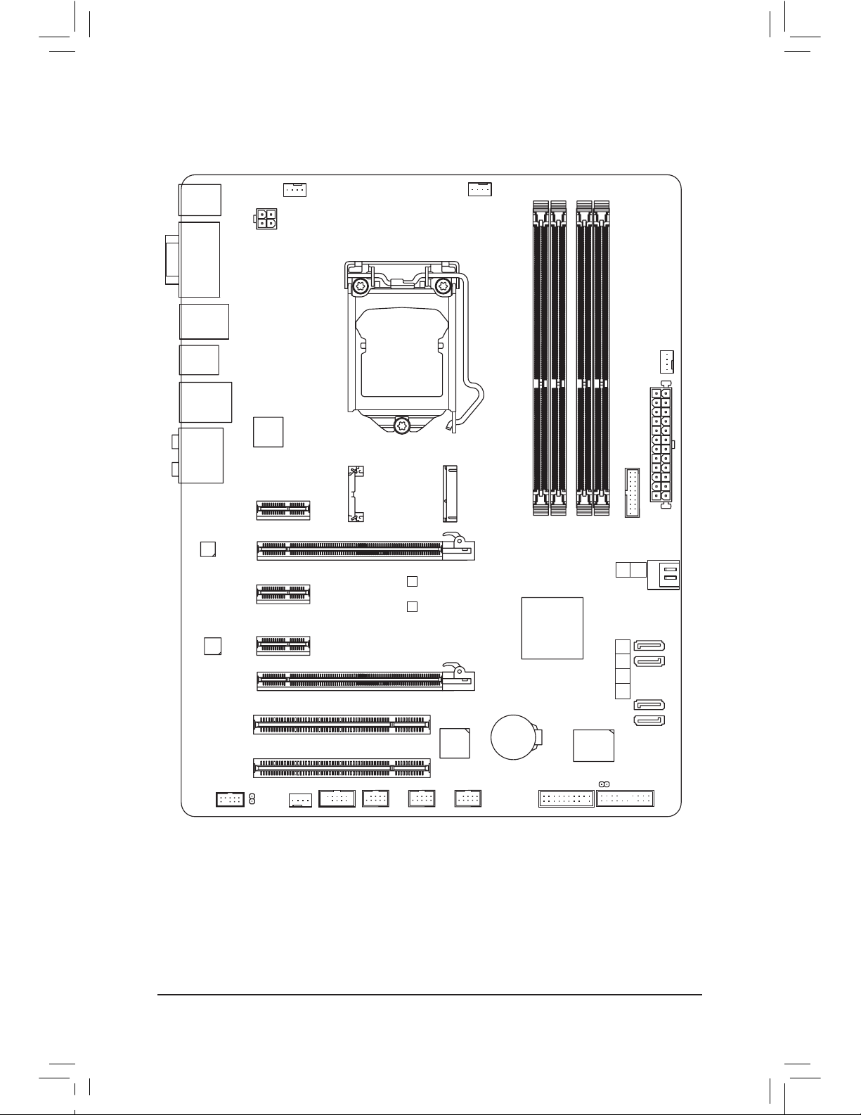
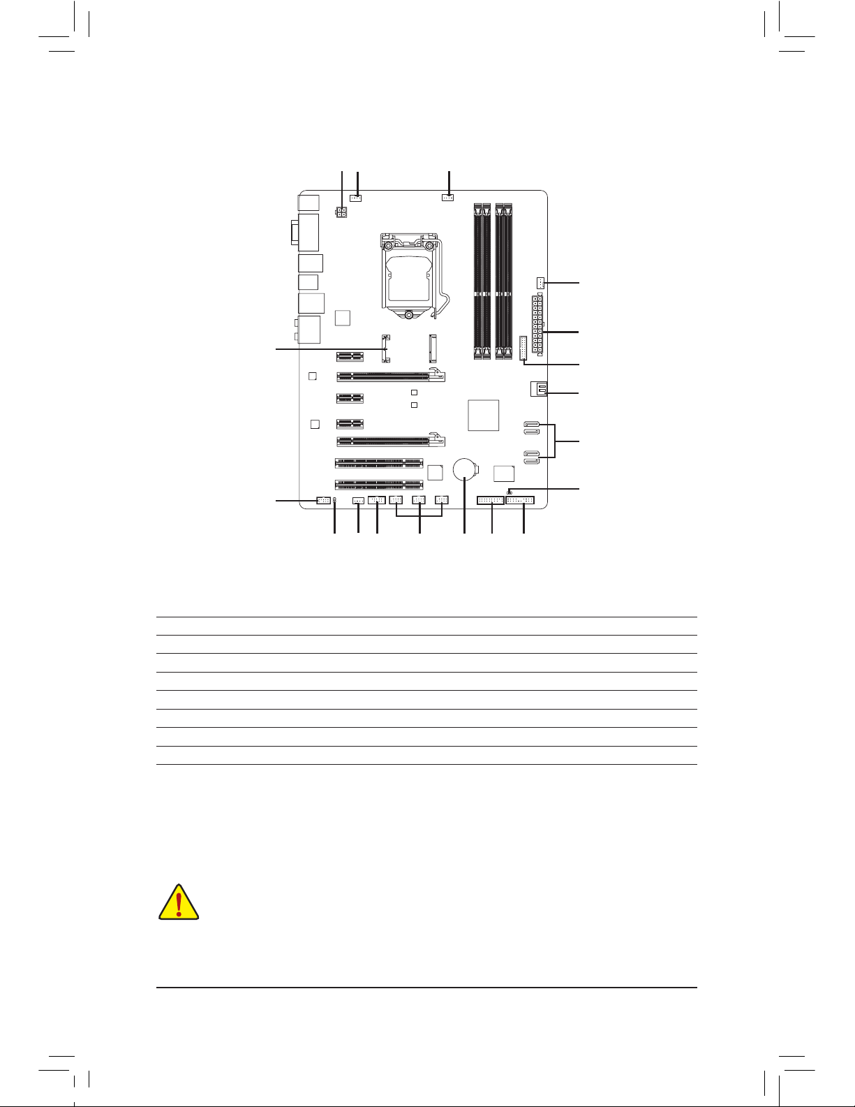
GA-Z77-D3H/GA-H77-D3H-MVP/GA-H77-D3H Motherboard Layout
KB_MS_USB
CPU_FAN
ATX_12V
ATX
F_AUDIO
AUDIO
B_BIOS
PCIEX4
DDR3_2
DDR3_1
DDR3_4
DDR3_3
BAT
F_PANEL
COMA
Intel
®
Z77
j
Intel® H77
kl
PCI2
CLR_CMOS
CODEC
SYS_FAN2
M_BIOS
PCIEX1_2
PCIEX16
SPDIF_O
F_USB1
LGA1155
DVI VGA
HDMI
R_USB30_2
R_USB30_1
USB_LAN
A t h er o s
GbE LAN
PCI1
F_USB30
PCIEX1_3
PCIe to PCI
Bridge
SYS_FAN3
SATA3
iTE
Super I/O
SYS_FAN1
F_USB2
F_USB3
Etron
EJ168
mSATA
TPM
PCIEX1_1
1
0
2345
SATA2
j
Only for GA-Z77-D3H.
k
Only for GA-H77-D3H-MVP.
l
Only for GA-H77-D3H.
GA-Z77-D3H/GA-H77-D3H-MVP/
GA-H77-D3H
— 8 —
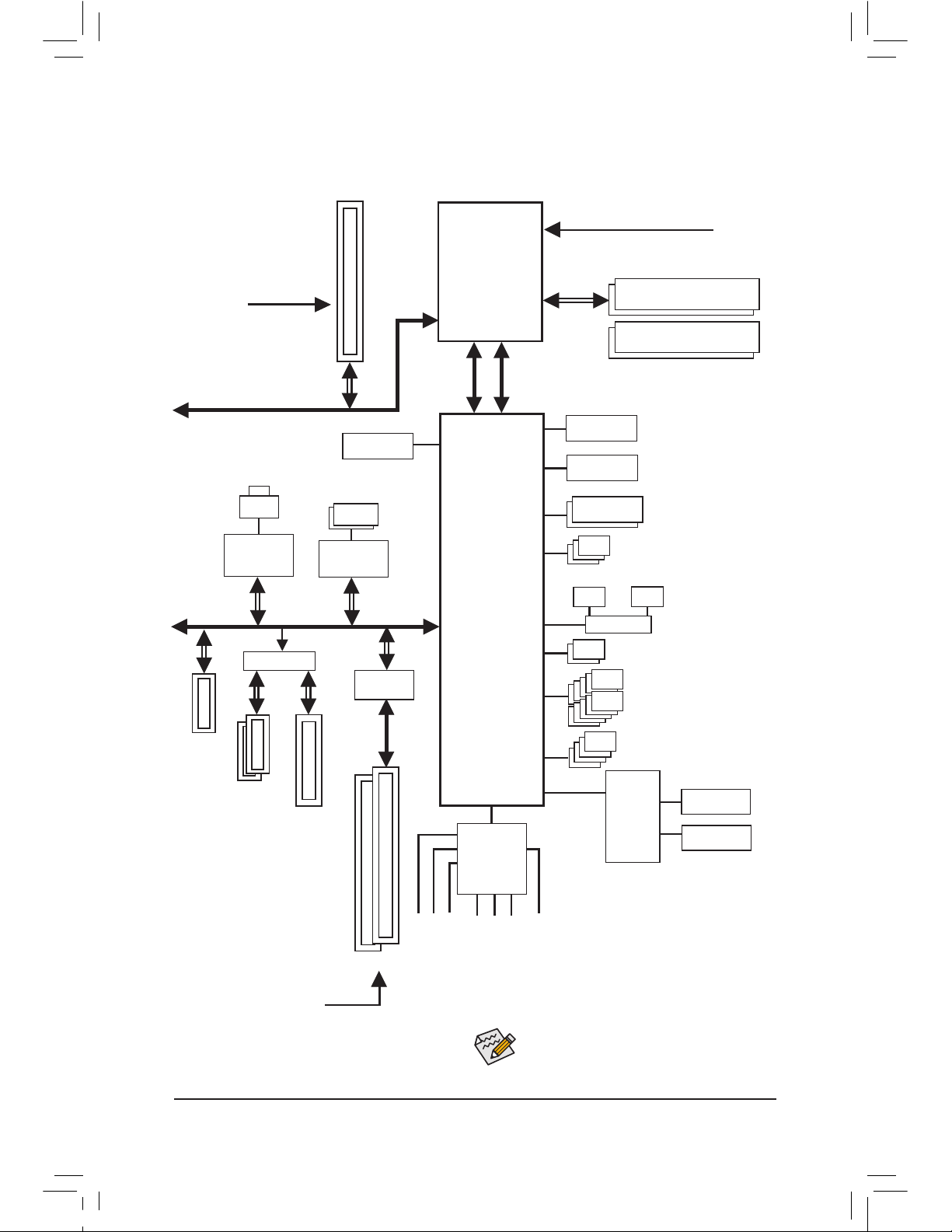
GA-Z77-D3H/GA-H77-D3H-MVP/GA-H77-D3H
Motherboard Block Diagram
Center/Subwoofer Speaker Out
Line Out
MIC
Line In
S/PDIF Out
Side Speaker Out
Surround Speaker Out
PS/2 KB/Mouse
LGA1155
CPU
DMI 2.0
FDI
CPU CLK+/- (100 MHz)
Dual BIOS
HDMI
10 USB 2.0/1.1
DDR3 1600/1333/1066 MHz
Dual Channel Memory
COM Port
LPC Bus
Intel® Z77
j
Intel
®
H77
kl
x1
2 USB 3.0/2.0
Etron
EJ168
iTE
Super
I/O
CODEC
PCIe CLK
(100 MHz)
PCI Express Bus
1 PCI Express x16
x1
LAN
RJ45
Atheros
GbE LAN
2 PCI
PCI Bus
PCI CLK
(33 MHz)
PCIe to PCI
Bridge
x1
Switch
or
x1
2 PCI Express x1
x4
1 PCI Express x4
PCI Express Bus
x16
D-Sub
DVI-D
4 USB 3.0/2.0
2 SATA 6Gb/s
1 SATA 3Gb/s
or
1 mSATA
3 SATA 3Gb/s
Switch
j
Only for GA-Z77-D3H.
k
Only for GA-H77-D3H-MVP.
l
Only for GA-H77-D3H.
x1
1 PCI Express x1
For detailed product information/limitation(s),
refer to «1-2 Product Specications.»

— 9 — Hardware Installation
1-1 Installation Precautions
The motherboard contains numerous delicate electronic circuits and components which can
become damaged as a result of electrostatic discharge (ESD). Prior to installation, carefully read
the user’s manual and follow these procedures:
Prior to installation, make sure the chassis is suitable for the motherboard.
•
Prior to installation, do not remove or break motherboard S/N (Serial Number) sticker or
•
warranty sticker provided by your dealer. These stickers are required for warranty validation.
Always remove the AC power by unplugging the power cord from the power outlet before
•
installing or removing the motherboard or other hardware components.
When connecting hardware components to the internal connectors on the motherboard,
•
make sure they are connected tightly and securely.
When handling the motherboard, avoid touching any metal leads or connectors.
•
It is best to wear an electrostatic discharge (ESD) wrist strap when handling electronic com-
•
ponents such as a motherboard, CPU or memory. If you do not have an ESD wrist strap,
keep your hands dry and rst touch a metal object to eliminate static electricity.
Prior to installing the motherboard, please have it on top of an antistatic pad or within an
•
electrostatic shielding container.
Before unplugging the power supply cable from the motherboard, make sure the power sup-
•
ply has been turned off.
Before turning on the power, make sure the power supply voltage has been set according to
•
the local voltage standard.
Before using the product, please verify that all cables and power connectors of your hard-
•
ware components are connected.
To prevent damage to the motherboard, do not allow screws to come in contact with the
•
motherboard circuit or its components.
Make sure there are no leftover screws or metal components placed on the motherboard or
•
within the computer casing.
Do not place the computer system on an uneven surface.
•
Do not place the computer system in a high-temperature environment.
•
Turning on the computer power during the installation process can lead to damage to sys-
•
tem components as well as physical harm to the user.
If you are uncertain about any installation steps or have a problem related to the use of the
•
product, please consult a certied computer technician.
Chapter 1 Hardware Installation
— 10 —Hardware Installation
1-2 Product Specications
CPU Support for Intel
®
Core™ i7 processors/Intel® Core™ i5 processors/
Intel® Core™ i3 processors/Intel® Pentium® processors/
Intel® Celeron® processors in the LGA1155 package
(Go to GIGABYTE’s website for the latest CPU support list.)
L3 cache varies with CPU
Chipset Intel
®
Z77j/Intel® H77kl Express Chipset
Memory 4 x 1.5V DDR3 DIMM sockets supporting up to 32 GB of system memory
* Due to Windows 32-bit operating system limitation, when more than 4 GB of physical
memory is installed, the actual memory size displayed will be less than 4 GB.
Dual channel memory architecture
Support for DDR3 1600/1333/1066 MHz memory modules
* To support DDR3 1600 MHz, you must install an Intel 22nm (Ivy Bridge) CPU.kl
Support for non-ECC memory modules
Support for Extreme Memory Prole (XMP) memory modules
* To support XMP memory, you must install an Intel 22nm (Ivy Bridge) CPU. kl
(Go to GIGABYTE’s website for the latest supported memory speeds and memory
modules.)
Onboard
Graphics
Integrated Graphics Processor:
— 1 x D-Sub port
— 1 x DVI-D port, supporting a maximum resolution of 1920×1200
* The DVI-D port does not support D-Sub connection by adapter.
— 1 x HDMI port, supporting a maximum resolution of 1920×1200
Audio VIA VT2021 codec
High Denition Audio
2/4/5.1/7.1-channel
Support for S/PDIF Out
LAN Atheros GbE LAN chip (10/100/1000 Mbit)
Expansion Slots 1 x PCI Express x16 slot, running at x16 (PCIEX16)
(The PCIEX16 slot conforms to PCI Express 3.0 standard.)
* For optimum performance, if only one PCI Express graphics card is to be installed,
be sure to install it in the PCIEX16 slot.
*
To support PCI Express 3.0, you must install an Intel 22nm (Ivy Bridge) CPU.
1 x PCI Express x16 slot, running at x4 (PCIEX4)
* The PCIEX4 slot shares bandwidth with the PCIEX1_2/3 slots. The PCIEX1_2/3 slots
will become unavailable when a PCIe x4 expansion card is installed.
3 x PCI Express x1 slots
(PCIEX4 and PCIEX1 slots conform to PCI Express 2.0 standard.)
2 x PCI slots
Multi-Graphics
Technology
Support for AMD CrossFireX™ technology
* The PCIEX16 slot operates at up to x4 mode when AMD CrossFireX™ is enabled.
j
Only for GA-Z77-D3H.
k
Only for GA-H77-D3H-MVP.
l
Only for GA-H77-D3H.
— 11 — Hardware Installation
Storage Interface Chipset:
— 2 x SATA 6Gb/s connectors (SATA3 0/SATA3 1) supporting up to 2 SATA
6Gb/s devices
— 4 x SATA 3Gb/s connectors (SATA2 2~SATA2 5) supporting up to 4 SATA
3Gb/s devices
— 1 x mSATA connector
* The SATA2 5 connector will become unavailable when the mSATA connector is
installed with a solid state drive.
— Support for RAID 0, RAID 1, RAID 5, and RAID 10
* When a RAID set is built across the SATA 6Gb/s and SATA 3Gb/s channels, the system
performance of the RAID set may vary depending on the devices being connected.
USB Chipset:
— Up to 4 USB 3.0/2.0 ports (2 ports on the back panel, 2 ports available through
the internal USB headers)
* In Windows XP, the Intel USB 3.0 ports can support up to USB 2.0 transfer speed.
— Up to 10 USB 2.0/1.1 ports (4 ports on the back panel, 6 ports available
through the internal USB headers)
Etron EJ168 chips:
— Up to 2 USB 3.0/2.0 ports on the back panel
Internal
Connectors
1 x 24-pin ATX main power connector
1 x 4-pin ATX 12V power connector
2 x SATA 6Gb/s connectors
4 x SATA 3Gb/s connectors
1 x mSATA connector
1 x CPU fan header
3 x system fan headers
1 x front panel header
1 x front panel audio header
1 x S/PDIF Out header
1 x USB 3.0/2.0 header
3 x USB 2.0/1.1 headers
1 x serial port header
1 x Clear CMOS jumper
1 x Trusted Platform Module (TPM) header
Back Panel
Connectors
1 x PS/2 keyboard/mouse port
1 x D-Sub port
1 x DVI-D port
1 x HDMI port
4 x USB 3.0/2.0 ports
4 x USB 2.0/1.1 ports
1 x RJ-45 port
1 x optical S/PDIF Out connector
5 x audio jacks (Center/Subwoofer Speaker Out, Rear Speaker
Out, Side Speaker Out, Line In/Mic In, Line Out)
— 12 —Hardware Installation
I/O Controller iTE I/O Controller Chip
Hardware
Monitor
System voltage detection
CPU/System temperature detection
CPU/System fan speed detection
CPU overheating warning
CPU/System fan fail warning
CPU/System fan speed control
* Whether the CPU/system fan speed control function is supported will depend on the
CPU/system cooler you install.
BIOS 2 x 64 Mbit ash
Use of licensed AMI EFI BIOS
Support for DualBIOS™
PnP 1.0a, DMI 2.0, SM BIOS 2.6, ACPI 2.0a
Unique Features Support for @BIOS
Support for Q-Flash
Support for Xpress Install
Support for Xpress Recovery2
Support for EasyTune
* Available functions in EasyTune may differ by motherboard model.
Support for eXtreme Hard Drive (X.H.D)
Support for Auto Green
Support for ON/OFF Charge
Support for Q-Share
Support for 3D Power
Support for EZ Setup
Bundled
Software
Norton Internet Security (OEM version)
Intel
®
Rapid Start Technology
Intel
®
Smart Connect Technology
Intel
®
Smart Response Technology
LucidLogix Virtu MVP jk
* Make sure the monitor cable has been connected to the integrated graphics port on
the back panel.
Operating
System
Support for Microsoft
®
Windows 7/XP
Form Factor ATX Form Factor; 30.5cm x 24.4cm
* GIGABYTE reserves the right to make any changes to the product specications and product-related information
without prior notice.
j
Only for GA-Z77-D3H.
k
Only for GA-H77-D3H-MVP.
— 13 — Hardware Installation
1-3 Installing the CPU and CPU Cooler
Read the following guidelines before you begin to install the CPU:
Make sure that the motherboard supports the CPU.
•
(Go to GIGABYTE’s website for the latest CPU support list.)
Always turn off the computer and unplug the power cord from the power outlet before installing
•
the CPU to prevent hardware damage.
Locate the pin one of the CPU. The CPU cannot be inserted if oriented incorrectly. (Or you may
•
locate the notches on both sides of the CPU and alignment keys on the CPU socket.)
Apply an even and thin layer of thermal grease on the surface of the CPU.
•
Do not turn on the computer if the CPU cooler is not installed, otherwise overheating and dam-
•
age of the CPU may occur.
Set the CPU host frequency in accordance with the CPU specications. It is not recommended
•
that the system bus frequency be set beyond hardware specications since it does not meet the
standard requirements for the peripherals. If you wish to set the frequency beyond the standard
specications, please do so according to your hardware specications including the CPU, graphics card, memory, hard drive, etc.
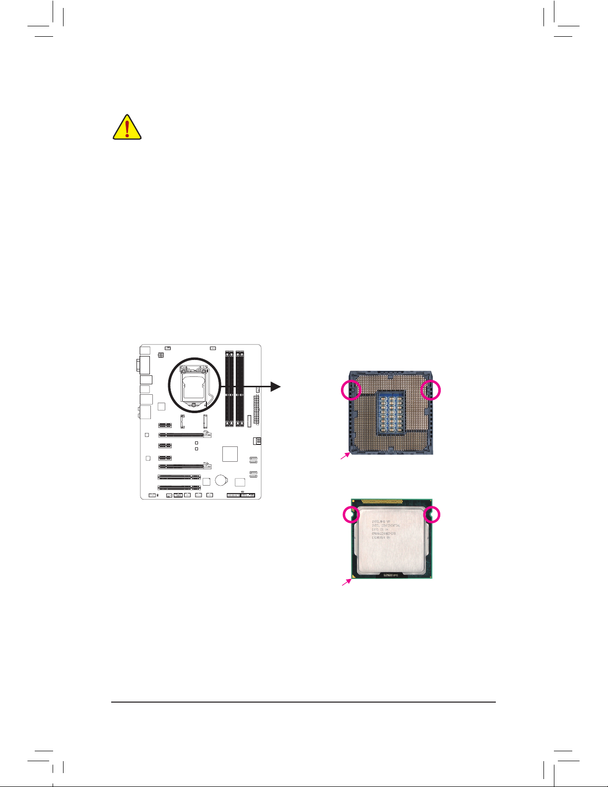
1-3-1 Installing the CPU
A. Locate the alignment keys on the motherboard CPU socket and the notches on the CPU.
Notch
Alignment KeyAlignment Key
Notch
LGA1155 CPU
LGA11
55 CPU Socket
Pin One Corner of the CPU Socket
Triangle Pin One Marking on the CPU
— 14 —Hardware Installation
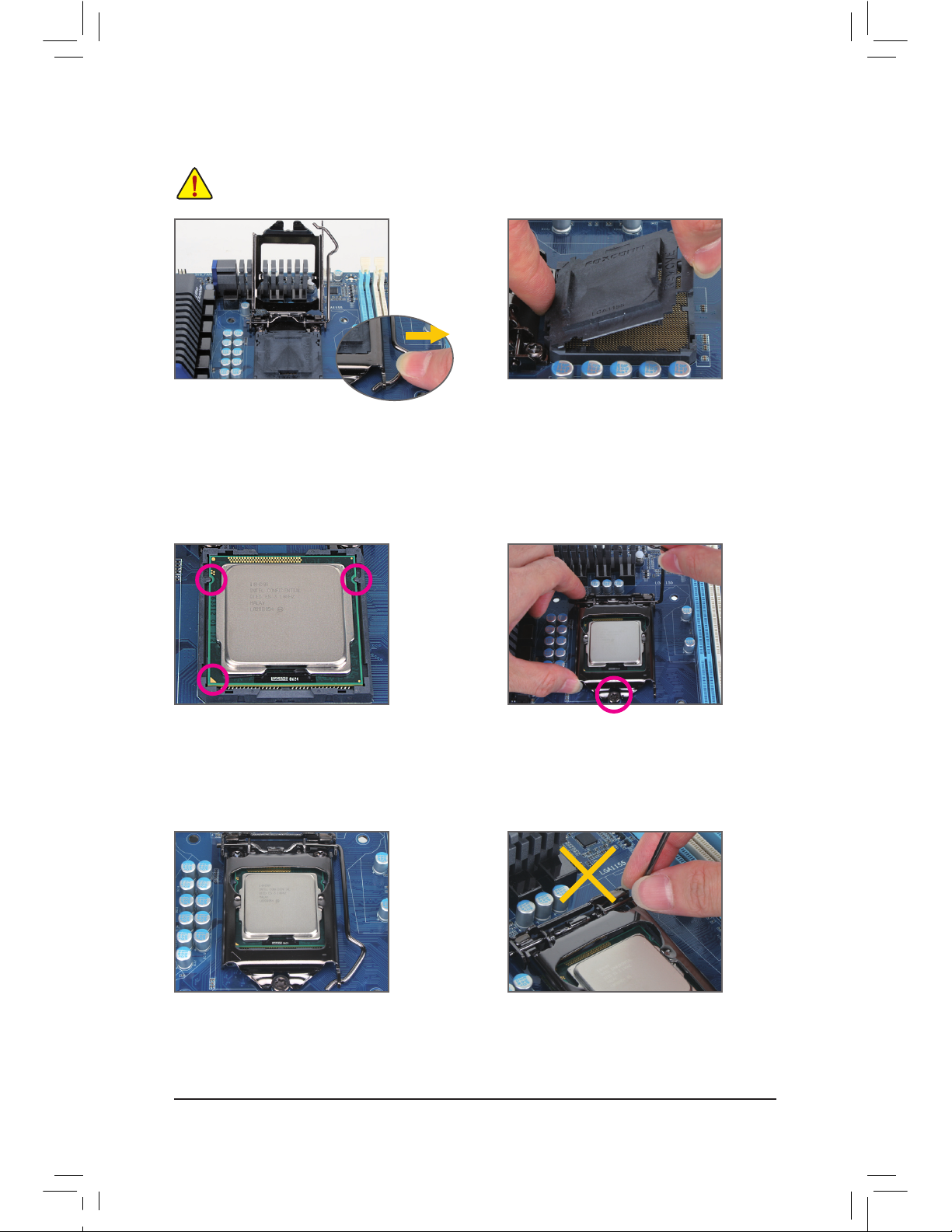
B. F
ollow the steps below to correctly install the CPU into the motherboard CPU socket.
Before installing the CPU, make sure to turn off the computer and unplug the power cord from
the power outlet to prevent damage to the CPU.
Step 1:
Gently p
ress the CPU socket lever handle down
and away from the socket with your nger. Then
completely lift the CPU socket lever and the
metal load plate will be lifted as well.
Step 3:
Ho
ld the CPU with your thumb and index ngers.
Align the CPU pin one marking (triangle) with the
pin one corner of the CPU socket (or you may
align the CPU notches with the socket alignment
keys) and gently insert the CPU into position.
Step 5:
Push t
he CPU socket lever back into its locked
position.
Step 4:
Once
the CPU is properly inserted, use one
hand to hold the socket lever and use the other
to lightly replace the load plate. When replacing
the load plate, make sure the front end of the
load plate is under the shoulder screw.
NOTE:
Ho
ld the CPU socket lever by the handle, not the
lever base portion.
Step 2:
Remove the CPU socket cover as shown. Hold
your index finger down on the rear grip of the
socket cover and use your thumb to lift up the
front edge (next to the «REMOVE» mark) and
then remove the cover. (DO NOT touch socket
contacts. To protect the CPU socket, always replace the protective socket cover when the CPU
is not installed.)
— 15 — Hardware Installation
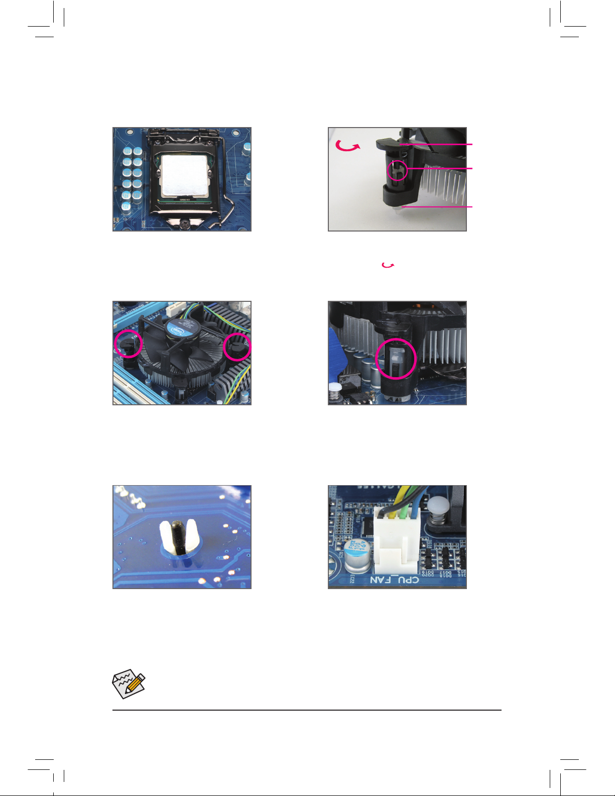
1-3-2 Installing the CPU Cooler
Follow the steps below to correctly install the CPU cooler on the motherboard. (The following procedure uses
Intel® boxed cooler as the example cooler.)
Use e
xtreme care when removing the CPU cooler because the thermal grease/tape between the
CPU cooler and CPU may adhere to the CPU. Inadequately removing the CPU cooler may damage
the CPU.
Step 1:
Apply an even and thin layer of thermal grease
on the surface of the installed CPU.
Male Push
Pin
Female
Push Pin
The Top of
Female
Push Pin
Direction of the
Arrow Sign on
the Male Push
Pin
Step 2:
Before installing the cooler, note the direction of
the arrow sign on the male push pin. (Turning the push pin along the direction of arrow is to
remove the cooler, on the contrary, is to install.)
Step 3:
Place t
he cooler atop the CPU, aligning the four
push pins through the pin holes on the motherboard. Push down on the push pins diagonally.
Step 4:
You should hear a «click» when pushing down
each push pin. Check that the Male and Female
push pins are joined closely.
(Refer to your CPU cooler installation manual for
instructions on installing the cooler.)
Step 5:
After the installation, check the back of the motherboard. If the push pin is inserted as the picture
above shows, the installation is complete.
Step 6:
Finally, attach the power connector of the CPU
cooler to the CPU fan header (CPU_FAN) on the
motherboard.
— 16 —Hardware Installation
1-4 Installing the Memory
Read the following guidelines before you begin to install the memory:
Make sure that the motherboard supports the memory. It is recommended that memory of the
•
same capacity, brand, speed, and chips be used.
(Go to GIGABYTE’s website for the latest supported memory speeds and memory modules.)
Always turn off the computer and unplug the power cord from the power outlet before installing
•
the memory to prevent hardware damage.
Memory modules have a foolproof design. A memory module can be installed in only one direc-
•
tion. If you are unable to insert the memory, switch the direction.
Dual Channel Memory Congurations Table
(SS=Single-Sided, DS=Double-Sided, «- -«=No Memory)
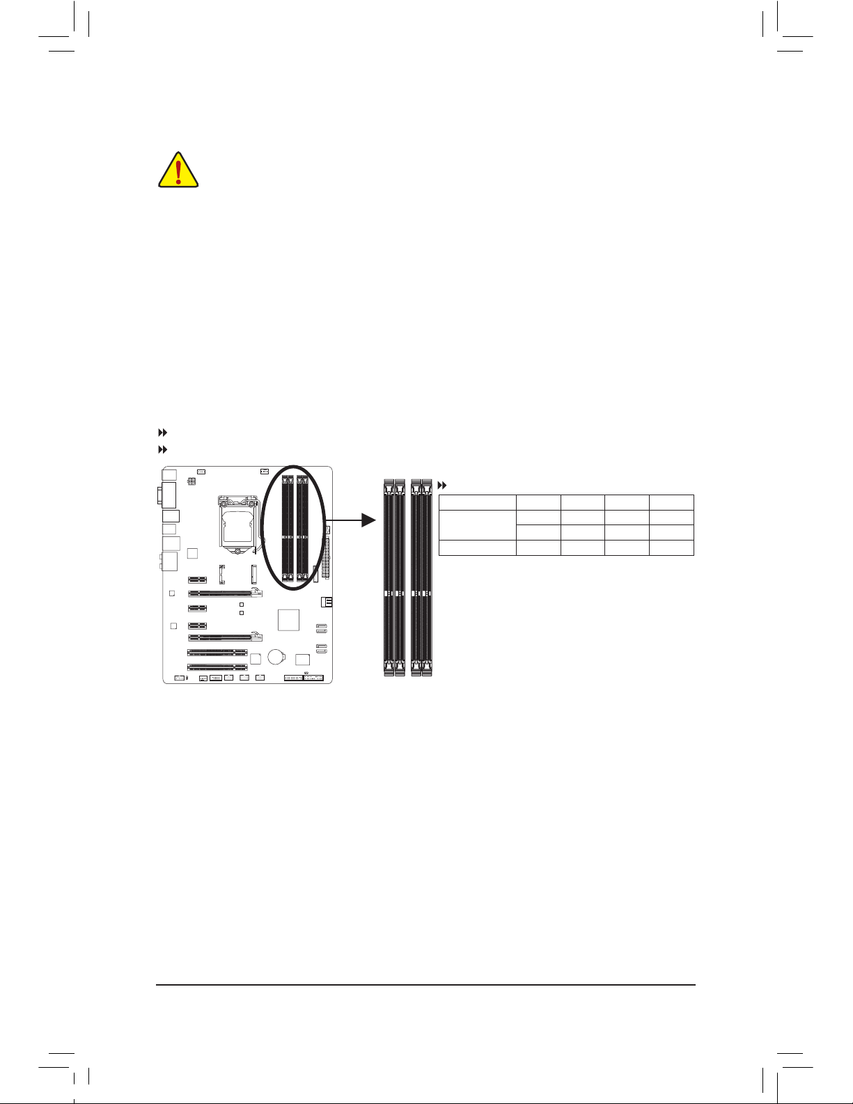
1-4-1 Dual Channel Memory Conguration
This motherboard provides four DDR3 memory sockets and supports Dual Channel Technology. After the
memory is installed, the BIOS will automatically detect the specications and capacity of the memory. Enabling Dual Channel memory mode will double the original memory bandwidth.
The four DDR3 memory sockets are divided into two channels and each channel has two memory sockets as
following:
Channel A: DDR3_4, DDR3_2
Channel B: DDR3_3, DDR3_1
DDR3_4
DDR3_2
DDR3_3
DDR3_1
Due to CPU limitations, read the following guidelines before installing the memory in Dual Channel mode.
Dual Channel mode cannot be enabled if only one DDR3 memory module is installed.1.
When enabling Dual Channel mode with two or four memory modules, it is recommended that 2.
memory of the same capacity, brand, speed, and chips be used and installed in the same colored
DDR3 sockets. For optimum performance, when enabling Dual Channel mode with two memory
modules, we recommend that you install them in the DDR3_1 and DDR3_2 sockets.
DDR3_4 DDR3_2 DDR3_3 DDR3_1
Tw
o Modules — — DS/SS — — DS/SS
DS/SS — — DS/SS — —
Four Modules DS/SS DS/SS DS/SS DS/SS
— 17 — Hardware Installation
1-4-2 Installing a Memory
Before installing a memory module, make sure to turn off the computer and unplug the power
cord from the power outlet to prevent damage to the memory module. DDR3 and DDR2 DIMMs
are not compatible to each other or DDR DIMMs. Be sure to install DDR3 DIMMs on this motherboard.
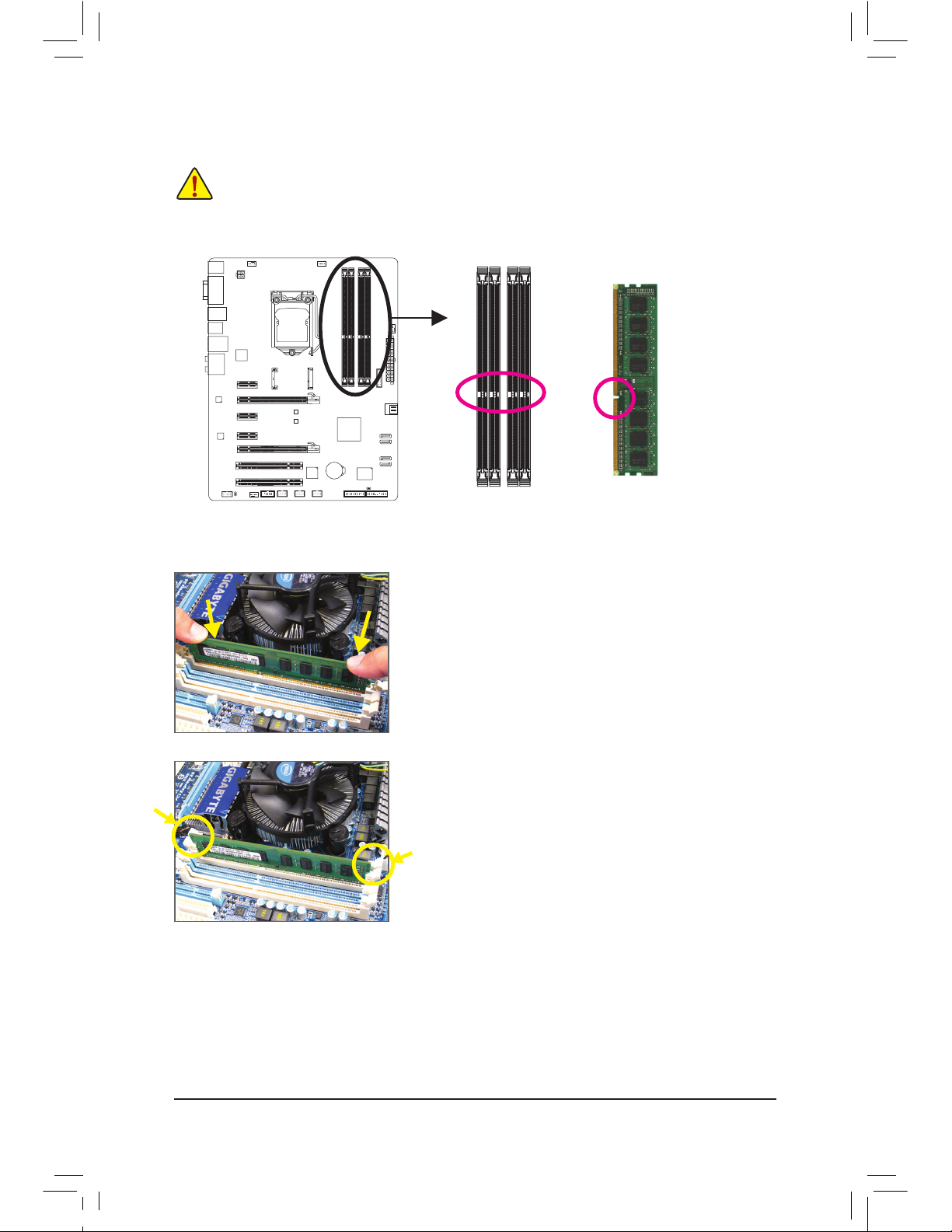
Notch
DDR3 DIMM
A DDR3 memory module has a notch, so it can only t in one direction. Follow the steps below to correctly
install your memory modules in the memory sockets.
Step 1:
Note
the orientation of the memory module. Spread the retaining
clips at both ends of the memory socket. Place the memory module
on the socket. As indicated in the picture on the left, place your ngers on the top edge of the memory, push down on the memory and
insert it vertically into the memory socket.
Step 2:
The clips at both ends of the socket will snap into place when the
memory module is securely inserted.
— 18 —Hardware Installation
1-5 Installing an Expansion Card
Read the following guidelines before you begin to install an expansion card:
Make sure the motherboard supports the expansion card. Carefully read the manual that came
•
with your expansion card.
Always turn off the computer and unplug the power cord from the power outlet before installing
•
an expansion card to prevent hardware damage.
Follow the steps below to correctly install your expansion card in the expansion slot.
1. Locate
an expansion slot that supports your card. Remove the metal slot cover from the chassis back
panel.
2. Align the card with the slot, and press down on the card until it is fully seated in the slot.
3. Make sure the metal contacts on the card are completely inserted into the slot.
4. Secure the card’s metal bracket to the chassis back panel with a screw.
5. After installing all expansion cards, replace the chassis cover(s).
6. Turn on your computer. If necessary, go to BIOS Setup to make any required BIOS changes for your expansion card(s).
7. Install the driver provided with the expansion card in your operating system.
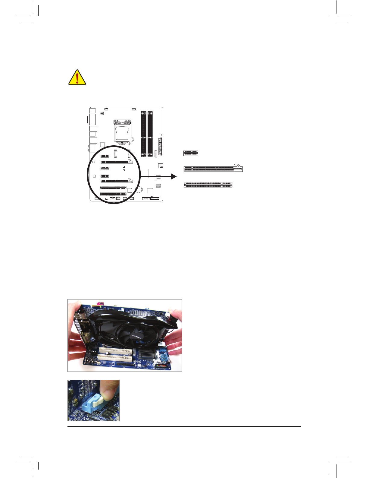
Example: Installing and Removing a PCI Express Graphics Card:
•InstallingaGraphicsCard:
Gently push down on the top edge of the card until
it is fully inserted into the PCI Express slot. Make
sure the card is securely seated in the slot and
does not rock.
•RemovingtheCard:
Press the latch at the end of the PCI Express slot to release the card and then
pull the card straight up from the slot.
PCI Express x1 Slot
PCI Express x16 Slot
PCI Slot
— 19 — Hardware Installation
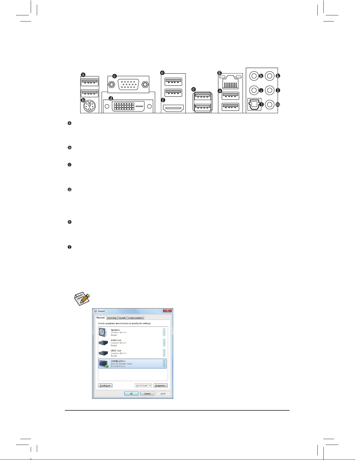
1-6 Back Panel Connectors
USB 2.0/1.1 Port
The USB port supports the USB 2.0/1.1 specication. Use this port for USB devices such as a USB keyboard/mouse, USB printer, USB ash drive and etc.
PS/2 Keyboard/Mouse Port
Use this port to connect a PS/2 mouse or keyboard.
D-Sub Port
The D-Sub port supports a 15-pin D-Sub connector. Connect a monitor that supports D-Sub connection
to this port.
DVI-D Port
(Note)
The DVI-D port conforms to the DVI-D specicationand supports a maximum resolution of 1920×1200 (the
actual resolutions supported depend on the monitor being used). Connect a monitor that supports DVI-D
connection to this port.
USB 3.0/2.0 Port
The USB 3.0 port supports the USB 3.0 specication and is compatible to the USB 2.0/1.1 specication.
Use this port for USB devices such as a USB keyboard/mouse, USB printer, USB ash drive and etc.
HDMI Port
HDMI (High-Denition Multimedia Interface) is an all-digital audio/video interface capable of transmitting uncompressed audio/video signals. The HDMI port is HDCP compliant and supports Dolby TrueHD
and DTS HD Master Audio formats. It also supports up to 192KHz/24bit 8-channel LPCM audio output.
You can use this port to connect your HDMI-supported monitor. The maximum supported resolution is
1920×1200, but the actual resolutions supported are dependent on the monitor being used.
In Windows 7, select Start>Control Panel>Hardware
and Sound>Sound>Playback, set Intel(R) Display Audio
to the default playback device.
(Note) The DVI-D port does not support D-Sub connection by adapter.
After installing the HDMI device, make sure to set the default sound playback device to HDMI.
(The item name may differ depending on your operating system. The screenshot below is from Windows 7.)
— 20 —Hardware Installation
Center/Subwoofer Speaker Out Jack (Orange)
Use this audio jack to connect center/subwoofer speakers in a 5.1/7.1-channel audio conguration.
Rear Speaker Out Jack (Black)
This jack can be used to connect front speakers in a 4/5.1/7.1-channel audio conguration.
Optical S/PDIF Out Connector
This connector provides digital audio out to an external audio system that supports digital optical audio.
Before using this feature, ensure that your audio system provides an optical digital audio in connector.
Line In Jack (Blue)
The default line in jack. Use this audio jack for line in devices such as an optical drive, walkman, etc.
Line Out Jack (Green)
The default line out jack. Use this audio jack for a headphone or 2-channel speaker. This jack can be
used to connect front speakers in a 4/5.1/7.1-channel audio conguration.
Mic In Jack (Pink)
The default Mic in jack. Microphones must be connected to this jack.
When r
emoving the cable connected to a back panel connector, rst remove the cable from
•
your device and then remove it from the motherboard.
When removing the cable, pull it straight out from the connector. Do not rock it side to side to
•
prevent an electrical short inside the cable connector.
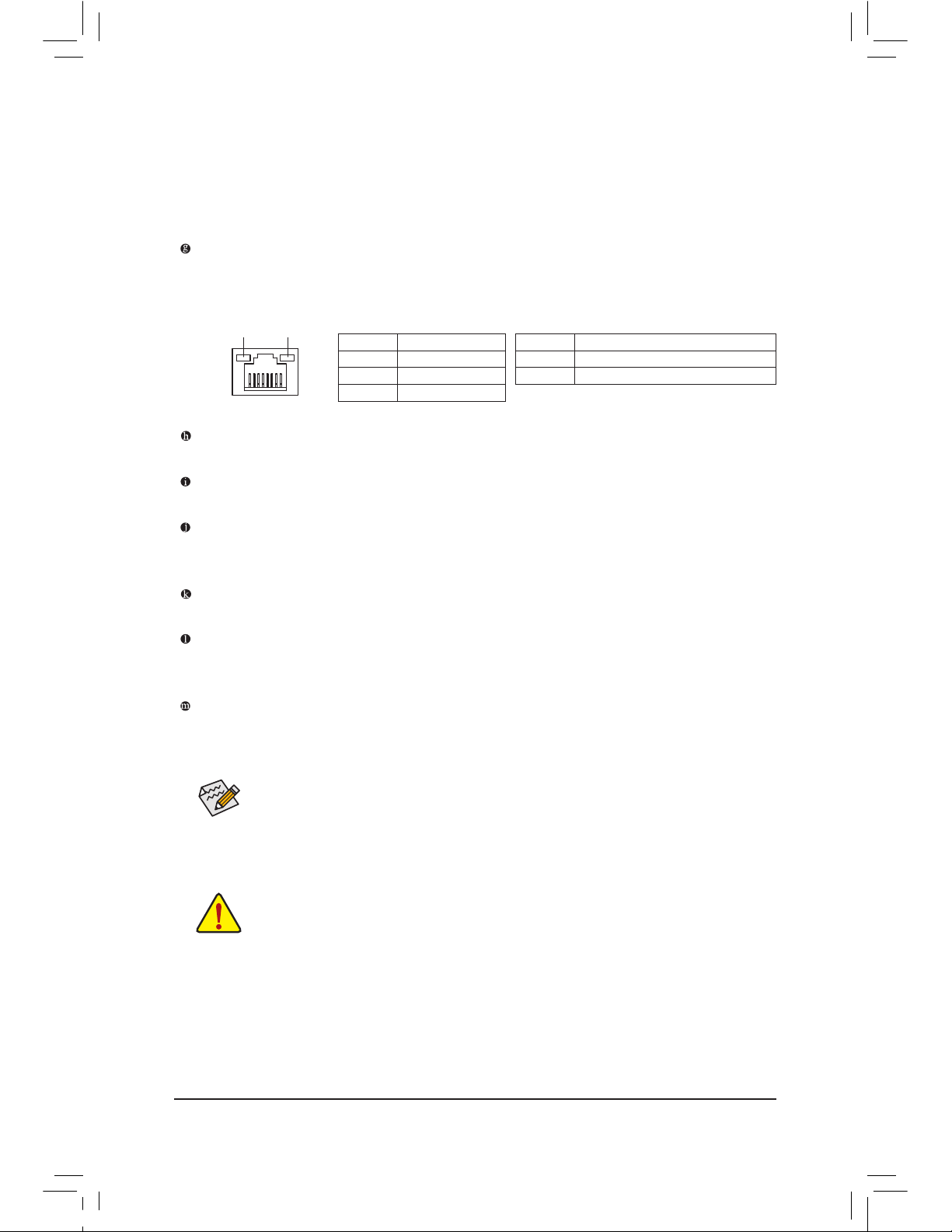
Activity LED
Connection/
Speed LED
LAN Port
Activity LED:Connection/Speed LED:
State Description
Orange 1 Gbps data rate
Green 100 Mbps data rate
Off 10 Mbps data rate
State Description
Blinking Data transmission or receiving is occurring
Off No data transmission or receiving is occurring
RJ-45 LAN Port
The Gigabit Ethernet LAN port provides Internet connection at up to 1 Gbps data rate. The following
describes the states of the LAN port LEDs.
The audio jacks can be recongured to perform different functions via the audio software.
If you
install a Side Speaker, you need to retask other audio jack to be Side Speaker out.
Only microphones still MUST be connected to the default Mic in jack. Refer to the instructions on setting up
a 2/4/5.1/7.1-channel audio conguration in Chapter 5, «Conguring 2/4/5.1/7.1-Channel Audio.»
Dual Display Congurations for the Onboard Graphics:
This motherboard provides three video output ports: D-Sub, DVI-D, and HDMI. Dual monitor confgurations are supported in operating system environment only, but not during the BIOS Setup or POST process.
— 21 — Hardware Installation
1-7 Internal Connectors
Read the following guidelines before connecting external devices:
First make sure your devices are compliant with the connectors you wish to connect.
•
Before installing the devices, be sure to turn off the devices and your computer. Unplug the
•
power cord from the power outlet to prevent damage to the devices.
After installing the device and before turning on the computer, make sure the device cable has
•
been securely attached to the connector on the motherboard.
14
1
2
4
4
1315
8
6
12
9
16
3
5
7
4
11
1) ATX_12V
2) AT
X
3) CPU_FA
N
4) SYS_FA
N1/2/3
5) BAT
6) SATA
3 0/1
7) SATA
2 2/3/4/5
 mSATA
mSATA
9) CLR_CMOS
10) F_PA
NEL
11
) F_AUDIO
12) SPDIF_O
13) F_USB1/F_USB2/F_USB3
14) F_USB30
15) COMA
16) TPM
10
— 22 —Hardware Installation
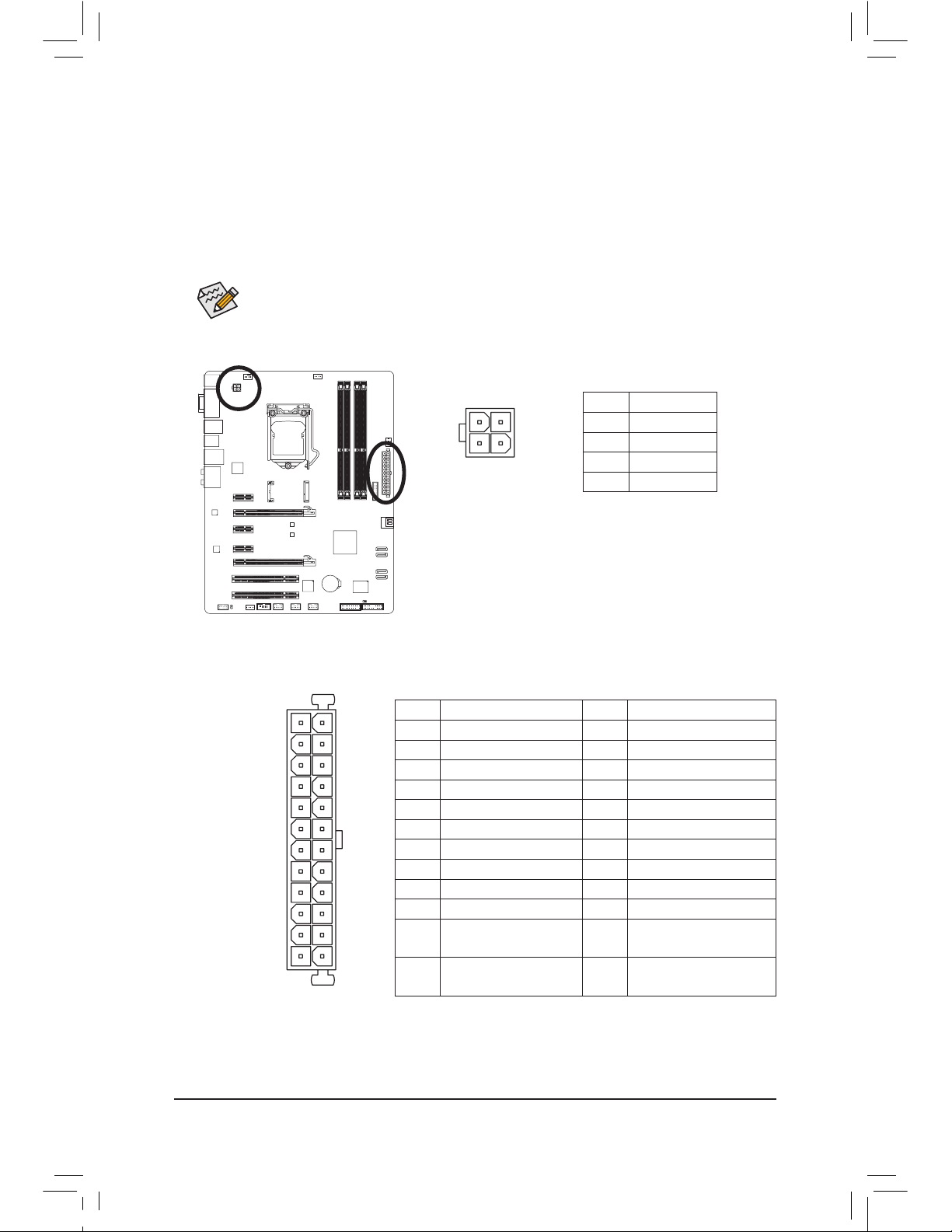
1/2) ATX_12V/ATX (2×2 12V Power Connector and 2×12 Main Power Connector)
With the use of the power connector, the power supply can supply enough stable power to all the components on the motherboard. Before connecting the power connector, rst make sure the power supply
is turned off and all devices are properly installed. The power connector possesses a foolproof design.
Connect the power supply cable to the power connector in the correct orientation.
The 12V power connector mainly supplies power to the CPU. If the 12V power connector is not connected, the computer will not start.
To
meet expansion requirements, it is recommended that a power supply that can withstand high
power consumption be used (500W or greater). If a power supply is used that does not provide
the required power, the result can lead to an unstable or unbootable system.
131
2412
AT
X
ATX:
Pin No. Denition Pin No. Denition
1 3.3V 13 3.3V
2 3.3V 14 -12V
3 GND 15 GND
4 +5V 16 PS_ON (soft On/Off
)
5 GND 17 GND
6 +5V 18 GND
7 GND 19 GND
8 Power Good 20 -5V
9 5VSB (stand by +5V) 21 +5V
10 +12V 22 +5V
11 +12V (Only for 2×12-pin
ATX)
23 +5V (Only for 2×12-pin ATX)
12 3.3V (Onl y for 2×12-pi n
ATX)
24 G ND (Onl y for 2×12-p in
ATX)
ATX_12V:
Pin No. Denition
1 GND
2 GND
3 +12V
4 +12V
ATX_12V
2
1
4
3
— 23 — Hardware Installation
Be sure to connect fan cables to the fan headers to prevent your CPU and system from over-
•
heating. Overheating may result in damage to the CPU or the system may hang.
These fan headers are not conguration jumper blocks. Do not place a jumper cap on the
•
headers.
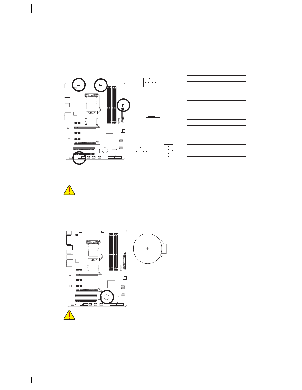
3/4) CPU_FAN/SYS_FAN1/SYS_FAN2/SYS_FAN3 (Fan Headers)
All fan headers on this motherboard are 4-pin. Most fan headers possess a foolproof insertion design.
When connecting a fan cable, be sure to connect it in the correct orientation (the black connector wire is
the ground wire). The speed control function requires the use of a fan with fan speed control design. For
optimum heat dissipation, it is recommended that a system fan be installed inside the chassis.
CPU_FAN:
Pin No. Denition
1 GND
2 +12V /Speed Control
3 Sense
4 Speed Control
SYS_FAN1:
Pin No. Denition
1 GND
2 +12V /Speed Control
3 Sense
4 Reserve
CPU_FAN
SYS_FAN1
1
1
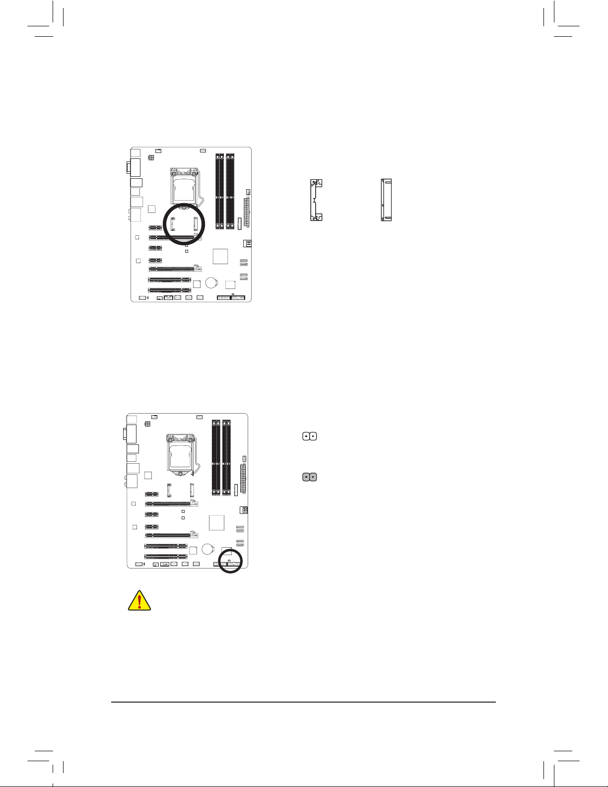
5) BAT (Battery)
The battery provides power to keep the values (such as BIOS congurations, date, and time information)
in t
he CMOS when the computer is turned off. Replace the battery when the battery voltage drops to a
low level, or the CMOS values may not be accurate or may be lost.
You may clear the CMOS values by removing the battery:
1. Tu
rn off your computer and unplug the power cord.
2. Gently
remove the battery from the battery holder and wait for one
minute. (
Or use a metal object like a screwdriver to touch the positive
and n
egative terminals of the battery holder, making them short for 5
seconds.)
3. R
eplace the battery.
4. P
lug in the power cord and restart your computer.
Always turn off
your computer and unplug the power cord before replacing the battery.
•
Replace t
he battery with an equivalent one. Danger of explosion if the battery is replaced with an incorrect
•
model.
Contact t
he place of purchase or local dealer if you are not able to replace the battery by yourself or uncer-
•
tain about the battery model.
When i
nstalling the battery, note the orientation of the positive side (+) and the negative side (-) of the bat-
•
tery (the positive side should face up).
Used batteries must be handled in accordance with local environmental regulations.
•
SYS_FAN2
1
SYS_FAN 2/3:
Pin No. Denition
1 GND
2 +12V
3 Sense
4 Speed Control
— 24 —Hardware Installation
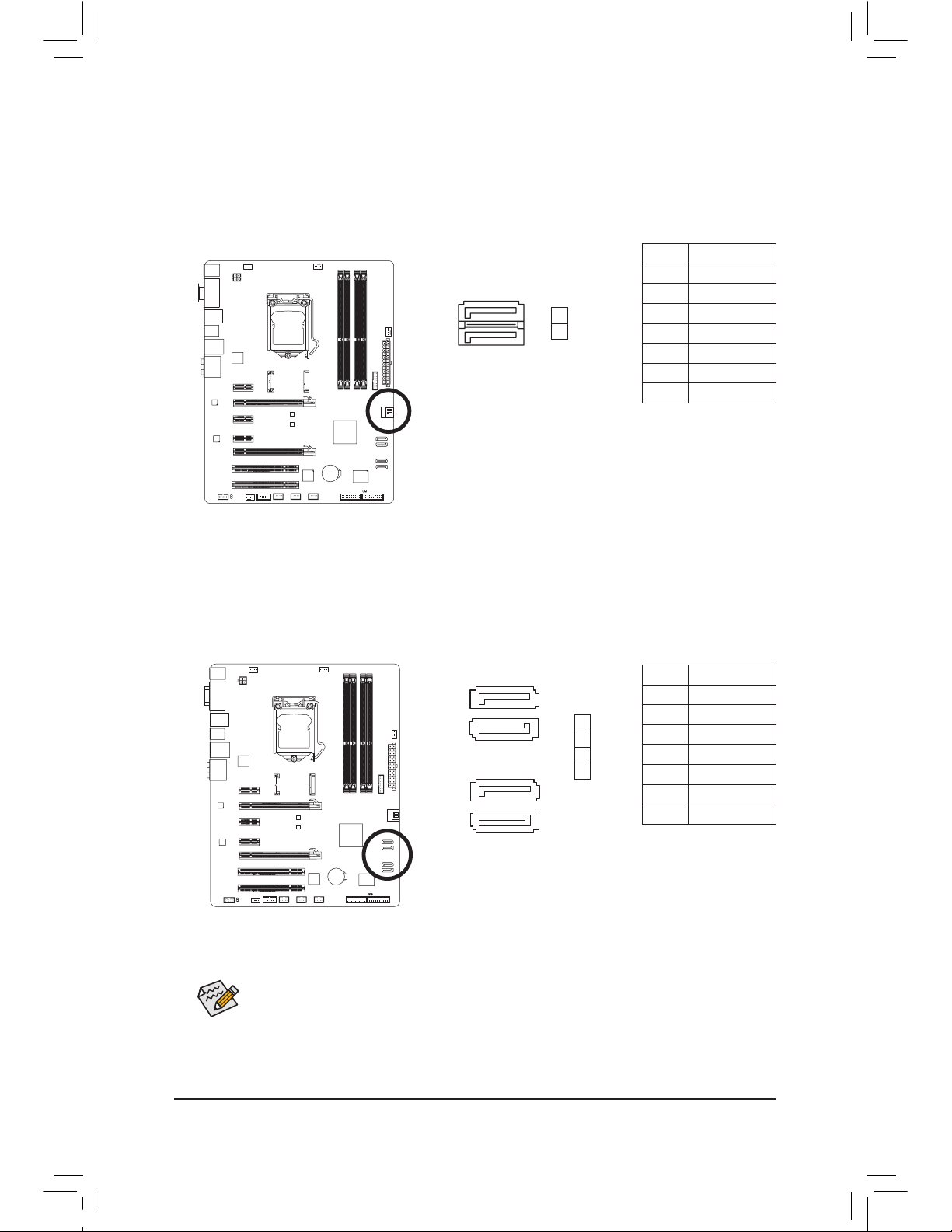
7) SATA2 2/3/4/5 (SATA 3Gb/s Connectors, Controlled by Intel Z77/H77 Chipset)
The SATA connectors conform to SATA 3Gb/s standard and are compatible with SATA 1.5Gb/s standard.
Each SATA connector supports a single SATA device.
(Please use the included SATA 3Gb/s cable)
. The
Intel Z77/H77 Chipset supports RAID 0, RAID 1, RAID 5, and RAID 10. Refer to Chapter 5, «Conguring
SATA Hard Drive(s),» for instructions on conguring a RAID array.
6) SATA3 0/1 (SATA 6Gb/s Connectors, Controlled by Intel Z77/H77 Chipset)
The SATA connectors conform to SATA 6Gb/s standard and are compatible with SATA 3Gb/s and SATA
1.5Gb/s standard. Each SATA connector supports a single SATA device. (Please use the included SATA
6Gb/s cable).
The SATA3 0/1 connectors support RAID 0 and RAID 1. RAID 5 and RAID 10 can be im-
plemented on the two connectors with the «SATA2 2/3/4/5» and mSATA connectors
(Note)
. Refer to Chapter
5, «Conguring SATA Hard Drive(s),» for instructions on conguring a RAID array.
A RAID
0 or RAID 1 conguration requires at least two hard drives. If more than two hard
•
drives are to be used, the total number of hard drives must be an even number.
A RAID 5 conguration requires at least three hard drives. (The total number of hard drives
•
does not have to be an even number.)
A RAID 10 conguration requires four hard drives.
•
(Note) When a RAID set is built across the SATA 6Gb/s and SATA 3Gb/s channels, the system perfor-
mance of the RAID set may vary depending on the devices being connected.
1
1
SATA3
7
7
Pin No. Denition
1 GND
2 TXP
3 TXN
4 GND
5 RXN
6 RXP
7 GND
Pin No. Denition
1 GND
2 TXP
3 TXN
4 GND
5 RXN
6 RXP
7 GND
1
0
SATA
2
7
7
1
1
— 25 — Hardware Installation
mSATA (Solid-State Drive Connector, Controlled by the Intel Z77/H77 Chipset)
The mSATA connector conforms to SATA 3Gb/s standard and can connect to a single solid-state drive.
When the mSATA connector is installed with a solid-state drive, the SATA2 5 connector will become unavailable.
mSATA
9) CLR_CMOS (Clear CMOS Jumper)
Use this jumper to clear the CMOS values (e.g. date information and BIOS congurations) and reset the
CMOS values to factory defaults. To clear the CMOS values, use a metal object like a screwdriver to
touch the two pins for a few seconds.
Always turn off your computer and unplug the power cord from the power outlet before clear-
•
ing the CMOS values.
After system restart, go to BIOS Setup to load factory defaults (select Load Optimized De-
•
faults) or manually congure the BIOS settings (refer to Chapter 2, «BIOS Setup,» for BIOS
congurations).
Open: Normal
Short: Clear CMOS Va
lues
— 26 —Hardware Installation
The front panel design may differ by chassis. A front panel module mainly consists of power
switch, reset switch, power LED, hard drive activity LED, speaker and etc. When connecting your
chassis front panel module to this header, make sure the wire assignments and the pin assignments are matched correctly.
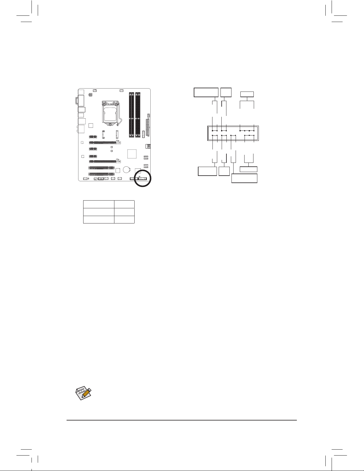
10) F_PANEL (Front Panel Header)
Connect the power switch, reset switch, speaker, chassis intrusion switch/sensor and system status
indicator on the chassis to this header according to the pin assignments below. Note the positive and
negative pins before connecting the cables.
• PW (Power Switch, Red):
C
onnects to the power switch on the chassis front panel. You may congure the way to turn off your
system using the power switch (refer to Chapter 2, «BIOS Setup,» «Power Management,» for more
information).
• SPEAK (Speaker, Orange):
C
onnects to the speaker on the chassis front panel. The system reports system startup status by issuing a beep code. One single short beep will be heard if no problem is detected at system startup.
• HD (Hard Drive Activity LED, Blue):
C
onnects to the hard drive activity LED on the chassis front panel. The LED is on when the hard drive
is reading or writing data.
• RES (Reset Switch, Green):
C
onnects to the reset switch on the chassis front panel. Press the reset switch to restart the computer
if the computer freezes and fails to perform a normal restart.
• CI (Chassis Intrusion Header, Gray):
C
onnects to the chassis intrusion switch/sensor on the chassis that can detect if the chassis cover
has been removed. This function requires a chassis with a chassis intrusion switch/sensor.
• MSG/PWR (Message/Power/Sleep LED, Yellow/Purple):
C
onnects to the power status indicator on the chassis front panel. The LED
is on when the system is operating. The LED is off when the system is in
S3/S4 sleep state or powered off (S5).
System Status LED
S0 On
S3/S4/S5 Off
Power LED
1
2
19
20
CI-
CI+
PWR-
PWR+
MSG-
PW-
SPEAK+
SPEAK-
MSG+
PW+
Message/Power/
Sleep LED
Speaker
Power
Switch
HD-
RES+
HD+
RES-
Hard Drive
Activity LED
Reset
Switch
Ch
assis Intrusion
Header
— 27 — Hardware Installation
11) F_AUDIO (Front Panel Audio Header)
The front panel audio header supports Intel High Denition audio (HD) and AC’97 audio. You may connect your chassis front panel audio module to this header. Make sure the wire assignments of the module connector match the pin assignments of the motherboard header. Incorrect connection between the
module connector and the motherboard header will make the device unable to work or even damage it.
The f
ront panel audio header supports HD audio by default. If your chassis provides an AC’97
•
front panel audio module, refer to the instructions on how to activate AC’97 functionality via
the audio software in Chapter 5, «Conguring 2/4/5.1/7.1-Channel Audio.»
Audio signals will be present on both of the front and back panel audio connections simultane-
•
ously. If you want to mute the back panel audio (only supported when using an HD front panel
audio module), refer to Chapter 5, «Conguring 2/4/5.1/7.1-Channel Audio.»
Some chassis provide a front panel audio module that has separated connectors on each wire
•
instead of a single plug. For information about connecting the front panel audio module that
has different wire assignments, please contact the chassis manufacturer.
For HD Front Panel Audio:
For AC’97 Front Panel Audio:
Pin No. Denition
1 MIC2_L
2 GND
3 MIC2_R
4 -ACZ_DET
5 LINE2_R
6 GND
7 FA
UDIO_JD
8 No Pin
9 LINE2_L
10 GND
Pin No. Denition
1 MIC
2 GND
3 MIC Power
4 NC
5 Line Out (R)
6 NC
7 NC
8 No Pin
9 Line Out (L)
10 NC
F_PANEL(NH) F_PANEL
(H61M-D2)
9 1
10 2
1
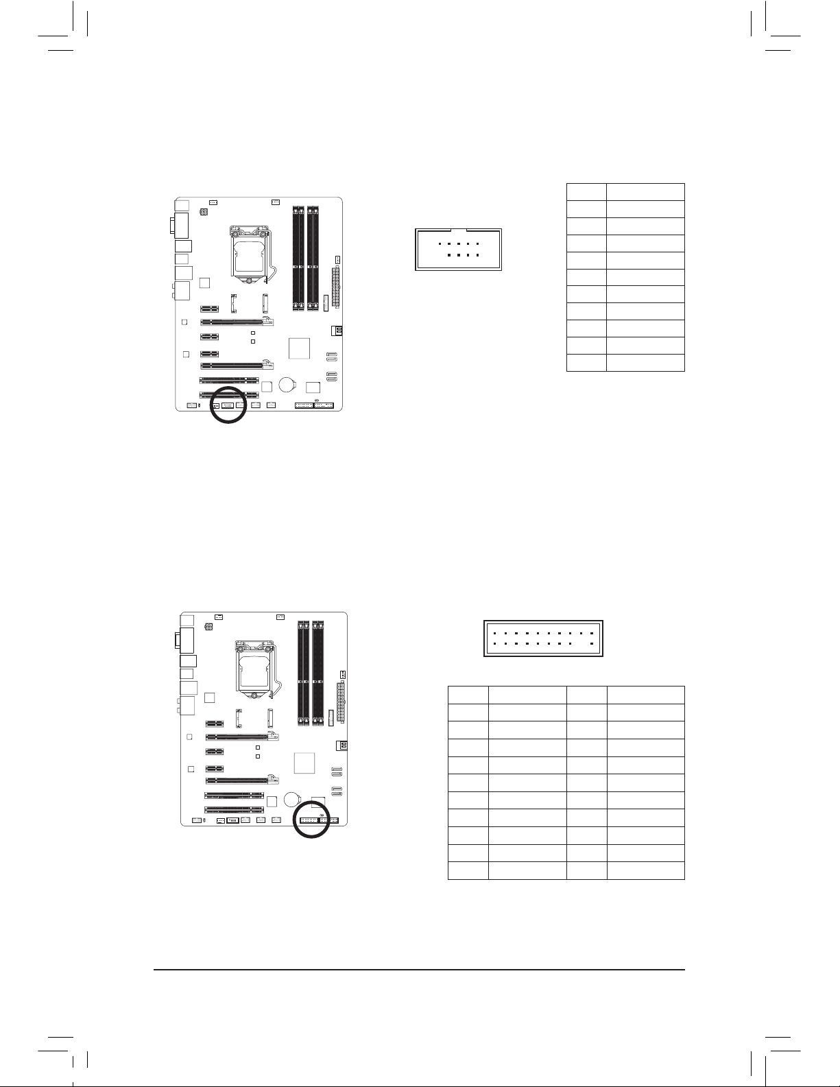
12) SPDIF_O (S/PDIF Out Header)
This header supports digital S/PDIF Out and connects a S/PDIF digital audio cable (provided by expansion cards) for digital audio output from your motherboard to certain expansion cards like graphics cards
and sound cards. For example, some graphics cards may require you to use a S/PDIF digital audio cable
for digital audio output from your motherboard to your graphics card if you wish to connect an HDMI display to the graphics card and have digital audio output from the HDMI display at the same time.
For information about connecting the S/PDIF digital audio cable, carefully read the manual for your expansion card.
Pin No. Denition
1 SPDIFO
2 GND
— 28 —Hardware Installation
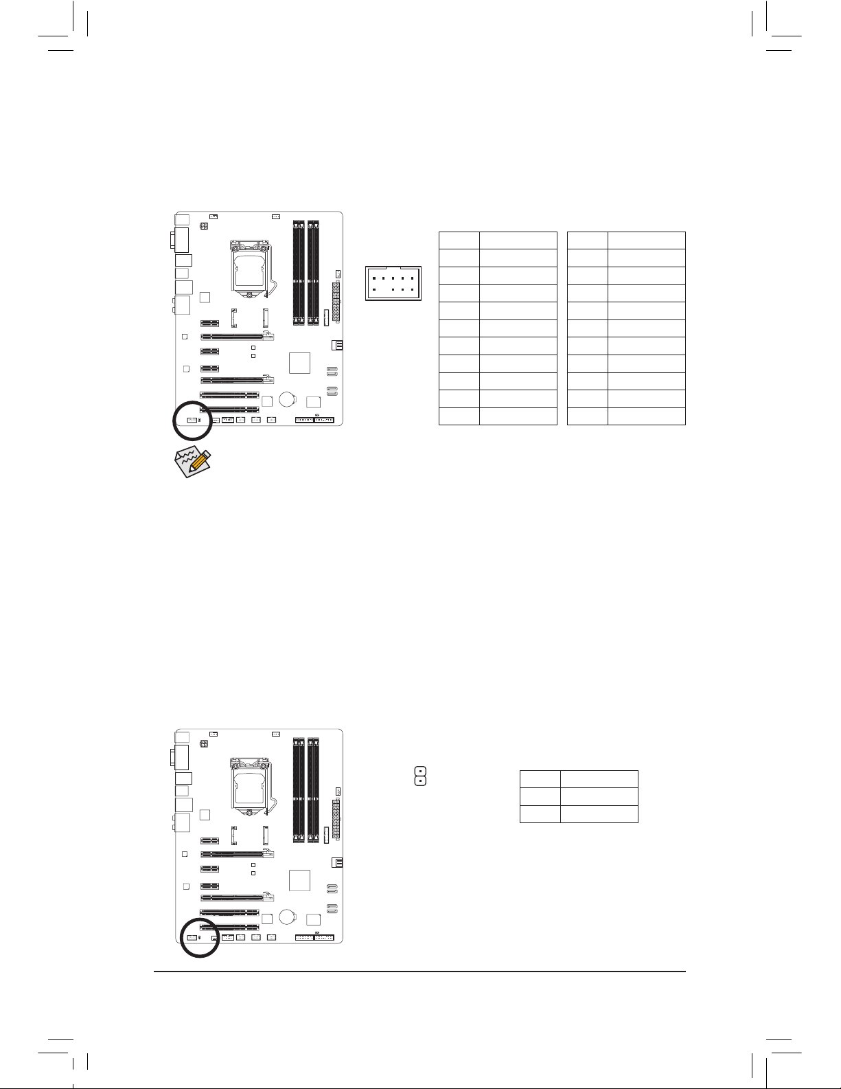
13) F_USB1/F_USB2/F_USB3 (USB 2.0/1.1 Headers)
The headers conform to USB 2.0/1.1 specication. Each USB header can provide two USB ports via an
optional USB bracket. For purchasing the optional USB bracket, please contact the local dealer.
10
9
2
1
Pin No. Denition
1 Power (5V)
2 Power (5V)
3 USB DX-
4 USB DY-
5 USB DX+
6 USB DY+
7 GND
8 GND
9 No Pin
10 NC
Do not plug the IEEE 1394 bracket (2×5-pin) cable into the USB 2.0/1.1 header.
•
Prior to installing the USB bracket, be sure to turn off your computer and unplug the power
•
cord from the power outlet to prevent damage to the USB bracket.
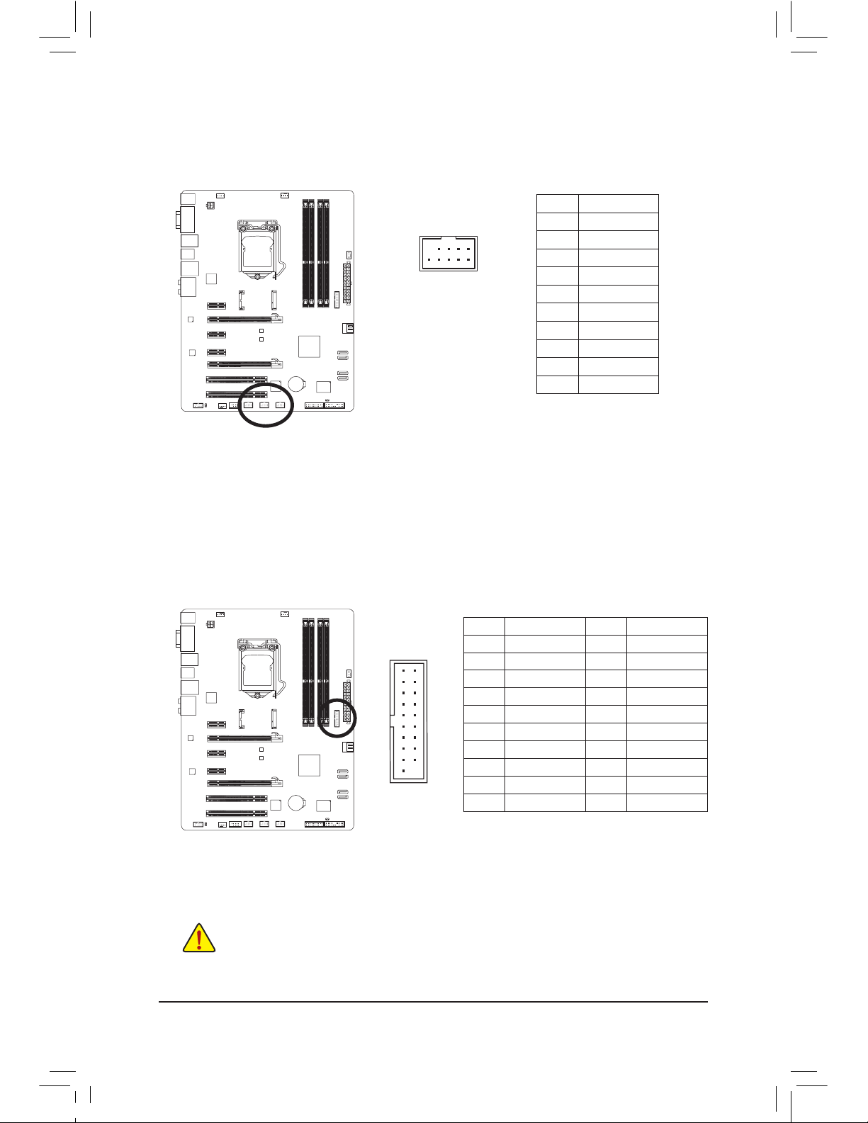
14) F_USB30 (USB 3.0/2.0 Header)
The header conforms to USB 3.0/2.0 specication and can provide two USB ports. For purchasing the
optional 3.5″ front panel that provides two USB 3.0/2.0 ports, please contact the local dealer.
F_AUDIO(H)
DB_PORT
F_PANEL(NH) F_PANEL
(H61M-D2)
10
11
20
1
Pin No. Denition Pin No. Denition
1 VBUS 11 D2+
2 SSRX1- 12 D2-
3 SSRX1+ 13 GND
4 GND 14 SSTX2+
5 SSTX1- 15 SSTX2-
6 SSTX1+ 16 GND
7 GND 17 SSRX2+
8 D1- 18 SSRX2-
9 D1+ 19 VBUS
10 NC 20 No Pin
— 29 — Hardware Installation
20
19
2
1
F_AUDIO(H)
DB_PORT
F_PANEL(NH) F_PANEL
(H61M-D2)
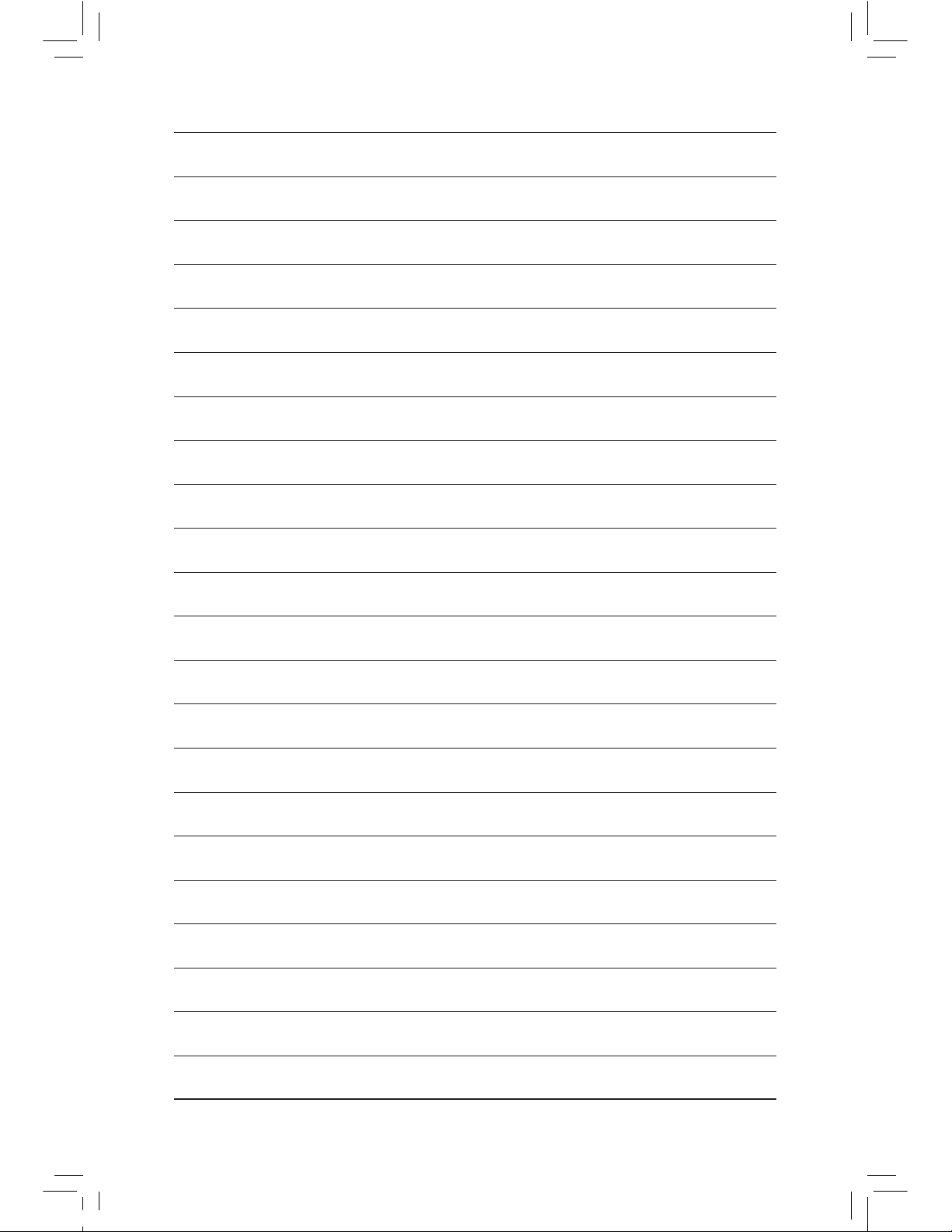
16) TPM (Trusted Platform Module Header)
You may connect a TPM (Trusted Platform Module) to this header.
Pin No. Denition Pin No. Denition
1 LCLK 11 LAD0
2 GND 12 GND
3 LFRAME 13 NC
4 No Pin 14 ID
5 LRESET 15 SB3V
6 NC 16 SERIRQ
7 LAD3 17 GND
8 LAD2 18 NC
9 VCC3 19 NC
10 LAD1 20 SUSCLK
10
9
2
1
15) COMA (Serial Port Header)
The COM header can provide one serial port via an optional COM port cable. For purchasing the optional COM port cable, please contact the local dealer.
Pin No. Denition
1 NDCD-
2 NSIN
3 NSOUT
4 NDTR-
5 GND
6 NDSR-
7 NRT
S-
8 NCTS-
9 NRI-
10 No Pin
— 30 —Hardware Installation
Loading…
The user manual for the Gigabyte GA-Z77-D3H and GA-H77-D3H motherboards.
- Addeddate
- 2021-04-16 09:36:56
- Identifier
- gigabyte-ga-z77-d3h-ga-h77-d3h-users-manual-rev.-1001
- Identifier-ark
- ark:/13960/t8sc4pf0j
- Ocr
- tesseract 5.0.0-alpha-20201231-10-g1236
- Ocr_detected_lang
- en
- Ocr_detected_lang_conf
- 1.0000
- Ocr_detected_script
- Latin
- Ocr_detected_script_conf
- 1.0000
- Ocr_module_version
- 0.0.13
- Ocr_parameters
- -l eng
- Page_number_confidence
- 89.32
- Ppi
- 600
comment
Reviews
There are no reviews yet. Be the first one to
write a review.
504
Views
DOWNLOAD OPTIONS
Temporarily Unavailable
DAISY
For users with print-disabilities
Temporarily Unavailable
EPUB
Uploaded by
sound.and.vision
on
-
Драйверы
33
-
Инструкции по эксплуатации
22
Языки:
Gigabyte GA-Z77-D3H инструкция по эксплуатации
(72 страницы)
- Языки:Венгерский, Греческий, Испанский, Итальянский, Немецкий, Польский, Португальский, Русский, Турецкий, Французский, Чешский
-
Тип:
PDF -
Размер:
18.6 MB -
Описание:
Installation Guidebook
На NoDevice можно скачать инструкцию по эксплуатации для Gigabyte GA-Z77-D3H. Руководство пользователя необходимо для ознакомления с правилами установки и эксплуатации Gigabyte GA-Z77-D3H. Инструкции по использованию помогут правильно настроить Gigabyte GA-Z77-D3H, исправить ошибки и выявить неполадки.
Gigabyte GA-Z77-D3H Motherboard PDF User Guides and Manuals for Free Download: Found (3) Manuals for Gigabyte GA-Z77-D3H Device Model (Operation & User’s Manual)
The Gigabyte GA-Z77-D3H motherboard is a solid entry in the industry, catering well to enthusiasts and casual gamers alike. With its rich feature set and firm build quality, it presents a reliable foundation for Intel’s third-generation processors. The Z77 chipset provides various capabilities that enhance the user experience, making this motherboard a popular choice among builders and upgraders.
One of the standout features of the GA-Z77-D3H is its support for Intel’s LGA 1155 socket, which allows users to harness the power of high-performance CPUs like the Intel Core i7. This compatibility ensures that users can pick from a wide range of processors to suit their performance needs. Furthermore, the motherboard supports up to 32GB of DDR3 RAM, enabling smooth multitasking and efficient handling of memory-intensive applications.
In terms of connectivity, the Gigabyte GA-Z77-D3H is quite comprehensive. It boasts:
- Four DIMM slots for DDR3 memory, supporting dual-channel configuration.
- Five SATA 3 connectors for fast storage solutions, including SSDs.
- Multiple USB 3.0 ports for quick data transfer and peripheral connection.
- Realtek ALC887 audio codec for decent onboard sound.
- PCI Express lanes for graphics cards, allowing for high-speed GPU performance.
On the performance front, users have reported that the GA-Z77-D3H handles overclocking well, particularly when paired with the right cooling solutions. The BIOS interface is user-friendly, making it accessible even to those new to tweaking their systems. Its intuitive layout allows users to alter settings for voltage, frequency, and more with relative ease.
Another plus for the GA-Z77-D3H is its multi-display support. With its HDMI and DVI outputs, users can easily set up dual monitors, which is particularly beneficial for content creators and gamers looking to enhance their productivity. The integrated graphics capabilities, paired with the right processor, can drive impressive visuals without needing a separate graphics card for everyday tasks.
However, there are a few considerations to keep in mind. The GA-Z77-D3H lacks some of the more advanced features found in higher-end motherboards, such as RGB lighting options or built-in Wi-Fi. Additionally, while the onboard audio is decent, audiophiles may want to invest in a dedicated sound card for better sound quality. Despite these minor downsides, the price point of the GA-Z77-D3H is competitive, making it a strong value proposition.
In conclusion, the Gigabyte GA-Z77-D3H is a commendable motherboard for users looking to build a robust system. Its array of features, solid performance for gaming and productivity, and strong compatibility with Intel processors make it an attractive option. Whether you are an enthusiast looking to overclock or a casual user seeking a reliable platform for daily tasks, the GA-Z77-D3H is worth considering for your next build.
Overall, Gigabyte has delivered a well-crafted motherboard in the GA-Z77-D3H, balancing performance, features, and cost effectiveness. If you are in the market for an Intel-compatible motherboard that won’t break the bank while still offering valuable features, then this model is highly recommended.