
Отклонения от заданной температуры процесса оказывают непосредственное влияние на свойства производимых пищевых продуктов. Таким образом, контроль/ мониторинг температуры является одним из решающих факторов в пищевой промышленности.
Особенно важным является контроль этого параметра во всех установках, где все зависит от того, чтобы определенный диапазон температур не был превышен и не был ниже минимально допустимого значения, в противном случае, конечный продукт будет необратимо испорчен.
Пример:
поддержание равномерной температуры шоколадной массы.
Чтобы избежать такого рода необратимых повреждений, JUMO предлагает Вам электронные или электромеханические термостаты, которые будут постоянно следить за температурным режимом Вашей системы.
Основные преимущества:
если достигается максимальная и минимальная температура системы или устройства, термостаты, утвержденные согласно DIN EN 14597, отключат нагрев или охлаждение и переведут систему в безопасный режим.
Предохранительный ограничитель температуры JUMO safetyM STB/STW.
Применение предохранительного ограничителя температуры (STB) и предохранительного реле температуры (STW) позволяет заблаговременно распознать и предотвратить опасности, которые могут привести к увечью людей, причинению ущерба окружающей среде или разрушению производственных установок и промежуточных изделий.
Главной задачей приборов является надежный контроль теплотехнических процессов и приведение установок в безопасное рабочее состояние при неисправностях. Измеряемое значение на аналоговом входе может быть получено с разных датчиков или через унифицированные сигналы.
Устройство контроля предельного значения имеет сигнализацию посредством светодиодов К1 и К2 (красный) для каждого канала, а встроенное реле тревоги приводит установку в безопасное состояние (в диапазоне тревог).
Высокие требования DIN EN 61508 как и DIN EN ISO 13849 выполняются благодаря концепции прибора, конструкция которого (1oo2D: 2-канальная структура с диагностическим каналом) гарантирует надежное обнаружение ошибок, поэтому может применяться также и в сферах, требующих соблюдения директивы по машиностроению 2006/42/ЕС.
2014-05-01
/00564764
(translation of the German
Operating Manual
original manual)
B 701150.0
according to DIN EN 14597
safety temperature monitor
JUMO safetyM STB/STW
Safety temperature limiter,
Operating overview

Operating overview . . . . . . . . . . . . . . . . . . . . . . . . . . . . . . . . . . . . . . . . . . . . . . . . . . . . . . . . . . . 2
1 Brief description . . . . . . . . . . . . . . . . . . . . . . . . . . . . . . . . . . . . . . . . . . . . . . . . . . . . . . . . . . . . 10
1.1 Safety temperature monitor (STW) . . . . . . . . . . . . . . . . . . . . . . . . . . . . . . . . . . . . . . . . . . . . . . . . . . . . .10
1.2 Safety temperature limiter (STB). . . . . . . . . . . . . . . . . . . . . . . . . . . . . . . . . . . . . . . . . . . . . . . . . . . . . . .10
1.3 Safety information. . . . . . . . . . . . . . . . . . . . . . . . . . . . . . . . . . . . . . . . . . . . . . . . . . . . . . . . . . . . . . . . . .11
2 Identifying the device version . . . . . . . . . . . . . . . . . . . . . . . . . . . . . . . . . . . . . . . . . . . . . . . . . 12
2.1 Scope of delivery . . . . . . . . . . . . . . . . . . . . . . . . . . . . . . . . . . . . . . . . . . . . . . . . . . . . . . . . . . . . . . . . . .14
2.2 Device software versions . . . . . . . . . . . . . . . . . . . . . . . . . . . . . . . . . . . . . . . . . . . . . . . . . . . . . . . . . . . .15
2.3 Serial number . . . . . . . . . . . . . . . . . . . . . . . . . . . . . . . . . . . . . . . . . . . . . . . . . . . . . . . . . . . . . . . . . . . . .15
2.4 Service addresses . . . . . . . . . . . . . . . . . . . . . . . . . . . . . . . . . . . . . . . . . . . . . . . . . . . . . . . . . . . . . . . . .15
3 Installation . . . . . . . . . . . . . . . . . . . . . . . . . . . . . . . . . . . . . . . . . . . . . . . . . . . . . . . . . . . . . . . . . 17
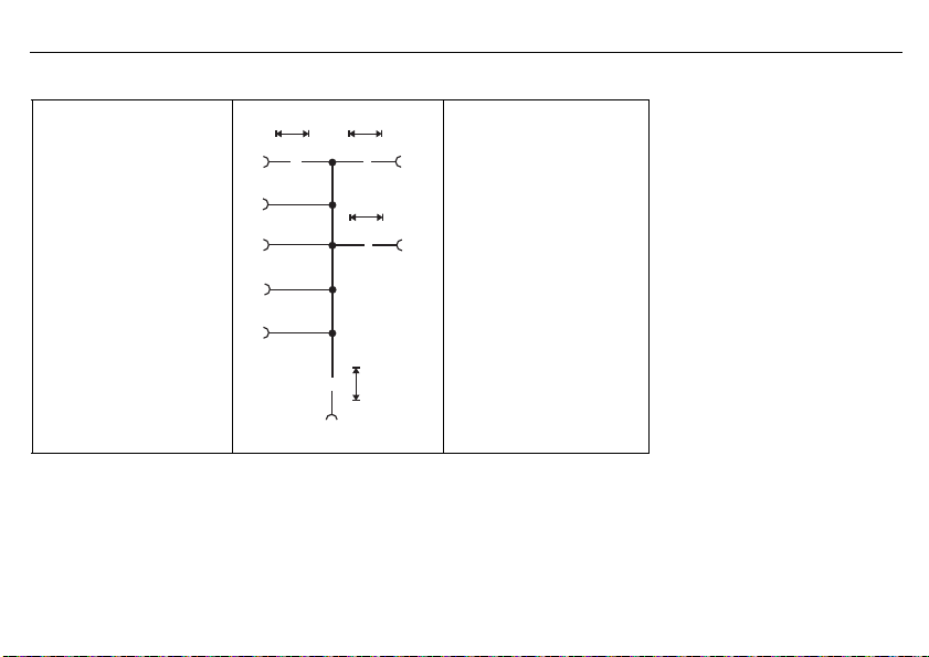
3.1 Dimensions . . . . . . . . . . . . . . . . . . . . . . . . . . . . . . . . . . . . . . . . . . . . . . . . . . . . . . . . . . . . . . . . . . . . . . .17
3.2 Installation location, DIN rail installation. . . . . . . . . . . . . . . . . . . . . . . . . . . . . . . . . . . . . . . . . . . . . . . . .18
3.3 Close mounting. . . . . . . . . . . . . . . . . . . . . . . . . . . . . . . . . . . . . . . . . . . . . . . . . . . . . . . . . . . . . . . . . . . .18
3.4 Dismantling . . . . . . . . . . . . . . . . . . . . . . . . . . . . . . . . . . . . . . . . . . . . . . . . . . . . . . . . . . . . . . . . . . . . . . .19
3.5 Electrical isolation. . . . . . . . . . . . . . . . . . . . . . . . . . . . . . . . . . . . . . . . . . . . . . . . . . . . . . . . . . . . . . . . . .20
3.6 Use of the setup interface . . . . . . . . . . . . . . . . . . . . . . . . . . . . . . . . . . . . . . . . . . . . . . . . . . . . . . . . . . .20
4 Electrical connection . . . . . . . . . . . . . . . . . . . . . . . . . . . . . . . . . . . . . . . . . . . . . . . . . . . . . . . . 21
4.1 Installation notes. . . . . . . . . . . . . . . . . . . . . . . . . . . . . . . . . . . . . . . . . . . . . . . . . . . . . . . . . . . . . . . . . . .21
4.2 Connection diagram . . . . . . . . . . . . . . . . . . . . . . . . . . . . . . . . . . . . . . . . . . . . . . . . . . . . . . . . . . . . . . . .23
5 Commissioning the device . . . . . . . . . . . . . . . . . . . . . . . . . . . . . . . . . . . . . . . . . . . . . . . . . . . . 27
5.1 Display and operating elements . . . . . . . . . . . . . . . . . . . . . . . . . . . . . . . . . . . . . . . . . . . . . . . . . . . . . . .27
5.2 Setting the display after switch-on . . . . . . . . . . . . . . . . . . . . . . . . . . . . . . . . . . . . . . . . . . . . . . . . . . . . .27
Inhalt

Inhalt
5.3 Selecting and editing parameters (plausibility inquiry for input values) . . . . . . . . . . . . . . . . . . . . . . . . .29
5.4 Aborting edit . . . . . . . . . . . . . . . . . . . . . . . . . . . . . . . . . . . . . . . . . . . . . . . . . . . . . . . . . . . . . . . . . . . . . .30
5.5 Alarm acknowledgement using the Reset key (only for temperature limiters STB) . . . . . . . . . . . . . . . .30
5.6 Alarm acknowledgement via binary input (only for temperature limiters STB). . . . . . . . . . . . . . . . . . . .30
5.7 Lead sealing the device . . . . . . . . . . . . . . . . . . . . . . . . . . . . . . . . . . . . . . . . . . . . . . . . . . . . . . . . . . . . .31
6 Safety Manual . . . . . . . . . . . . . . . . . . . . . . . . . . . . . . . . . . . . . . . . . . . . . . . . . . . . . . . . . . . . . . 32
6.1 Brief description . . . . . . . . . . . . . . . . . . . . . . . . . . . . . . . . . . . . . . . . . . . . . . . . . . . . . . . . . . . . . . . . . . .32
6.2 Safety temperature monitor (STW) . . . . . . . . . . . . . . . . . . . . . . . . . . . . . . . . . . . . . . . . . . . . . . . . . . . . .32
6.2.1 Safe operating status STW . . . . . . . . . . . . . . . . . . . . . . . . . . . . . . . . . . . . . . . . . . . . . . . . . . . . . . . . . . . . . . . . . . . . . .32
6.3 Safety temperature limiter (STB). . . . . . . . . . . . . . . . . . . . . . . . . . . . . . . . . . . . . . . . . . . . . . . . . . . . . . .33
6.3.1 Safe operating status STB . . . . . . . . . . . . . . . . . . . . . . . . . . . . . . . . . . . . . . . . . . . . . . . . . . . . . . . . . . . . . . . . . . . . . .33
6.4 Relevant standards. . . . . . . . . . . . . . . . . . . . . . . . . . . . . . . . . . . . . . . . . . . . . . . . . . . . . . . . . . . . . . . . .33
6.5 Validity of the Safety Manual . . . . . . . . . . . . . . . . . . . . . . . . . . . . . . . . . . . . . . . . . . . . . . . . . . . . . . . . .34
6.6 Connection possibilities of the sensors (SIL) . . . . . . . . . . . . . . . . . . . . . . . . . . . . . . . . . . . . . . . . . . . . .34
6.7 Standards and definitions. . . . . . . . . . . . . . . . . . . . . . . . . . . . . . . . . . . . . . . . . . . . . . . . . . . . . . . . . . . .37
6.7.1 Terms and abbreviations acc. to DIN EN 14597 . . . . . . . . . . . . . . . . . . . . . . . . . . . . . . . . . . . . . . . . . . . . . . . . . . . . . .37
6.7.2 Terms and abbreviations acc. to DIN EN 61 508 and DIN EN 61 511. . . . . . . . . . . . . . . . . . . . . . . . . . . . . . . . . . . . . . 38
6.8 Safety instrumented parameters related to the temperature monitoring unit . . . . . . . . . . . . . . . . . . . .41
6.8.1 Failure rates and SFF for 701150…23 (AC 230 V) . . . . . . . . . . . . . . . . . . . . . . . . . . . . . . . . . . . . . . . . . . . . . . . . . . . . .41
6.8.2 Failure rates and SFF for 701150…25 (AC/DC 24 V) . . . . . . . . . . . . . . . . . . . . . . . . . . . . . . . . . . . . . . . . . . . . . . . . . . .42
6.9 Determining the Safety Integrity Level (SIL) . . . . . . . . . . . . . . . . . . . . . . . . . . . . . . . . . . . . . . . . . . . . . .43
6.9.1 Safety integrity of the hardware . . . . . . . . . . . . . . . . . . . . . . . . . . . . . . . . . . . . . . . . . . . . . . . . . . . . . . . . . . . . . . . . . . 45
6.9.2 Safety-relevant system properties . . . . . . . . . . . . . . . . . . . . . . . . . . . . . . . . . . . . . . . . . . . . . . . . . . . . . . . . . . . . . . . .46
6.10 Determining the achieved Performance Level PL. . . . . . . . . . . . . . . . . . . . . . . . . . . . . . . . . . . . . . . . . .48

6.10.1 Terms and abbreviations acc. to DIN EN ISO 13849 . . . . . . . . . . . . . . . . . . . . . . . . . . . . . . . . . . . . . . . . . . . . . . . . . .48
6.11 Connection possibilities of the sensors (PL). . . . . . . . . . . . . . . . . . . . . . . . . . . . . . . . . . . . . . . . . . . . . .51
6.11.1 Calculations DIN EN ISO 13849-1 Performance Level — low voltage 230 V . . . . . . . . . . . . . . . . . . . . . . . . . . . . . . . . .53
6.11.2 Calculations DIN EN ISO 13849-1 Performance Level — extra low voltage (ELV) 24 V . . . . . . . . . . . . . . . . . . . . . . . . .53
6.11.3 Contribution to risk minimization through the control system . . . . . . . . . . . . . . . . . . . . . . . . . . . . . . . . . . . . . . . . . . .54
6.12 Evaluating the achieved Performance Level PL and the relationship to the SIL . . . . . . . . . . . . . . . . . .56
6.13 Other applicable device documentation. . . . . . . . . . . . . . . . . . . . . . . . . . . . . . . . . . . . . . . . . . . . . . . . .59
6.14 Behavior during operation and in case of malfunction. . . . . . . . . . . . . . . . . . . . . . . . . . . . . . . . . . . . . .59
6.15 Regular tests. . . . . . . . . . . . . . . . . . . . . . . . . . . . . . . . . . . . . . . . . . . . . . . . . . . . . . . . . . . . . . . . . . . . . .59
6.15.1 Recommended tests for temperature probes . . . . . . . . . . . . . . . . . . . . . . . . . . . . . . . . . . . . . . . . . . . . . . . . . . . . . . . .59
6.16 Certificates . . . . . . . . . . . . . . . . . . . . . . . . . . . . . . . . . . . . . . . . . . . . . . . . . . . . . . . . . . . . . . . . . . . . . . .61
7 Configuration level . . . . . . . . . . . . . . . . . . . . . . . . . . . . . . . . . . . . . . . . . . . . . . . . . . . . . . . . . . 70
7.1 Navigation principle . . . . . . . . . . . . . . . . . . . . . . . . . . . . . . . . . . . . . . . . . . . . . . . . . . . . . . . . . . . . . . . .70
7.2 Analog inputs . . . . . . . . . . . . . . . . . . . . . . . . . . . . . . . . . . . . . . . . . . . . . . . . . . . . . . . . . . . . . . . . . . . . .71
7.2.1 Connection . . . . . . . . . . . . . . . . . . . . . . . . . . . . . . . . . . . . . . . . . . . . . . . . . . . . . . . . . . . . . . . . . . . . . . . . . . . . . . . . . .71
7.2.2 Sensor type 1 . . . . . . . . . . . . . . . . . . . . . . . . . . . . . . . . . . . . . . . . . . . . . . . . . . . . . . . . . . . . . . . . . . . . . . . . . . . . . . . .72
7.2.3 Offset 1 . . . . . . . . . . . . . . . . . . . . . . . . . . . . . . . . . . . . . . . . . . . . . . . . . . . . . . . . . . . . . . . . . . . . . . . . . . . . . . . . . . . . .73
7.2.4 Lead wire resistance 1 . . . . . . . . . . . . . . . . . . . . . . . . . . . . . . . . . . . . . . . . . . . . . . . . . . . . . . . . . . . . . . . . . . . . . . . . .73
7.2.5 Filter time 1 . . . . . . . . . . . . . . . . . . . . . . . . . . . . . . . . . . . . . . . . . . . . . . . . . . . . . . . . . . . . . . . . . . . . . . . . . . . . . . . . . .73
7.2.6 Scaling start 1 . . . . . . . . . . . . . . . . . . . . . . . . . . . . . . . . . . . . . . . . . . . . . . . . . . . . . . . . . . . . . . . . . . . . . . . . . . . . . . . .73
7.2.7 Scaling end 1 . . . . . . . . . . . . . . . . . . . . . . . . . . . . . . . . . . . . . . . . . . . . . . . . . . . . . . . . . . . . . . . . . . . . . . . . . . . . . . . . .73
7.2.8 Sensor type 2 . . . . . . . . . . . . . . . . . . . . . . . . . . . . . . . . . . . . . . . . . . . . . . . . . . . . . . . . . . . . . . . . . . . . . . . . . . . . . . . .74
7.2.9 Offset 2 . . . . . . . . . . . . . . . . . . . . . . . . . . . . . . . . . . . . . . . . . . . . . . . . . . . . . . . . . . . . . . . . . . . . . . . . . . . . . . . . . . . . .75
7.2.10 Lead wire resistance 2 . . . . . . . . . . . . . . . . . . . . . . . . . . . . . . . . . . . . . . . . . . . . . . . . . . . . . . . . . . . . . . . . . . . . . . . . .75
Inhalt

Inhalt
7.2.11 Filter time 2 . . . . . . . . . . . . . . . . . . . . . . . . . . . . . . . . . . . . . . . . . . . . . . . . . . . . . . . . . . . . . . . . . . . . . . . . . . . . . . . . . . 75
7.2.12 Scaling start 2 . . . . . . . . . . . . . . . . . . . . . . . . . . . . . . . . . . . . . . . . . . . . . . . . . . . . . . . . . . . . . . . . . . . . . . . . . . . . . . . .75
7.2.13 Scaling end 2 . . . . . . . . . . . . . . . . . . . . . . . . . . . . . . . . . . . . . . . . . . . . . . . . . . . . . . . . . . . . . . . . . . . . . . . . . . . . . . . . .75
7.3 Limiter/monitor . . . . . . . . . . . . . . . . . . . . . . . . . . . . . . . . . . . . . . . . . . . . . . . . . . . . . . . . . . . . . . . . . . . .76
7.3.1 Device function . . . . . . . . . . . . . . . . . . . . . . . . . . . . . . . . . . . . . . . . . . . . . . . . . . . . . . . . . . . . . . . . . . . . . . . . . . . . . . .76
7.3.2 Switching behavior . . . . . . . . . . . . . . . . . . . . . . . . . . . . . . . . . . . . . . . . . . . . . . . . . . . . . . . . . . . . . . . . . . . . . . . . . . . .77
7.3.3 Limit value, hysteresis . . . . . . . . . . . . . . . . . . . . . . . . . . . . . . . . . . . . . . . . . . . . . . . . . . . . . . . . . . . . . . . . . . . . . . . . . .79
7.3.4 Pre-alarm function . . . . . . . . . . . . . . . . . . . . . . . . . . . . . . . . . . . . . . . . . . . . . . . . . . . . . . . . . . . . . . . . . . . . . . . . . . . . .79
7.3.5 Pre-alarm, hysteresis . . . . . . . . . . . . . . . . . . . . . . . . . . . . . . . . . . . . . . . . . . . . . . . . . . . . . . . . . . . . . . . . . . . . . . . . . . .79
7.3.6 Limit value difference, hysteresis . . . . . . . . . . . . . . . . . . . . . . . . . . . . . . . . . . . . . . . . . . . . . . . . . . . . . . . . . . . . . . . . .80
7.3.7 Setting range min. (formerly ALHI) . . . . . . . . . . . . . . . . . . . . . . . . . . . . . . . . . . . . . . . . . . . . . . . . . . . . . . . . . . . . . . . 80
7.3.8 Setting range max. (formerly ALLO) . . . . . . . . . . . . . . . . . . . . . . . . . . . . . . . . . . . . . . . . . . . . . . . . . . . . . . . . . . . . . .80
7.4 Binary input. . . . . . . . . . . . . . . . . . . . . . . . . . . . . . . . . . . . . . . . . . . . . . . . . . . . . . . . . . . . . . . . . . . . . . .81
7.4.1 Function . . . . . . . . . . . . . . . . . . . . . . . . . . . . . . . . . . . . . . . . . . . . . . . . . . . . . . . . . . . . . . . . . . . . . . . . . . . . . . . . . . . . .81
7.5 Analog output . . . . . . . . . . . . . . . . . . . . . . . . . . . . . . . . . . . . . . . . . . . . . . . . . . . . . . . . . . . . . . . . . . . . .82
7.5.1 Function . . . . . . . . . . . . . . . . . . . . . . . . . . . . . . . . . . . . . . . . . . . . . . . . . . . . . . . . . . . . . . . . . . . . . . . . . . . . . . . . . . . . .82
7.5.2 Signal type . . . . . . . . . . . . . . . . . . . . . . . . . . . . . . . . . . . . . . . . . . . . . . . . . . . . . . . . . . . . . . . . . . . . . . . . . . . . . . . . . . .82
7.5.3 Scaling start . . . . . . . . . . . . . . . . . . . . . . . . . . . . . . . . . . . . . . . . . . . . . . . . . . . . . . . . . . . . . . . . . . . . . . . . . . . . . . . . .82
7.5.4 Scaling end . . . . . . . . . . . . . . . . . . . . . . . . . . . . . . . . . . . . . . . . . . . . . . . . . . . . . . . . . . . . . . . . . . . . . . . . . . . . . . . . . .82
7.5.5 Error signal . . . . . . . . . . . . . . . . . . . . . . . . . . . . . . . . . . . . . . . . . . . . . . . . . . . . . . . . . . . . . . . . . . . . . . . . . . . . . . . . . .83
7.5.6 Behavior when leaving the scaling range . . . . . . . . . . . . . . . . . . . . . . . . . . . . . . . . . . . . . . . . . . . . . . . . . . . . . . . . . . .84
7.6 Display/operation . . . . . . . . . . . . . . . . . . . . . . . . . . . . . . . . . . . . . . . . . . . . . . . . . . . . . . . . . . . . . . . . . .85
7.6.1 Language . . . . . . . . . . . . . . . . . . . . . . . . . . . . . . . . . . . . . . . . . . . . . . . . . . . . . . . . . . . . . . . . . . . . . . . . . . . . . . . . . . . .85
7.6.2 Unit . . . . . . . . . . . . . . . . . . . . . . . . . . . . . . . . . . . . . . . . . . . . . . . . . . . . . . . . . . . . . . . . . . . . . . . . . . . . . . . . . . . . . . . .85
7.6.3 Decimal place . . . . . . . . . . . . . . . . . . . . . . . . . . . . . . . . . . . . . . . . . . . . . . . . . . . . . . . . . . . . . . . . . . . . . . . . . . . . . . . .85

7.6.4 Normal display . . . . . . . . . . . . . . . . . . . . . . . . . . . . . . . . . . . . . . . . . . . . . . . . . . . . . . . . . . . . . . . . . . . . . . . . . . . . . . .85
7.6.5 Contrast . . . . . . . . . . . . . . . . . . . . . . . . . . . . . . . . . . . . . . . . . . . . . . . . . . . . . . . . . . . . . . . . . . . . . . . . . . . . . . . . . . . . .86
7.6.6 Lighting . . . . . . . . . . . . . . . . . . . . . . . . . . . . . . . . . . . . . . . . . . . . . . . . . . . . . . . . . . . . . . . . . . . . . . . . . . . . . . . . . . . . .86
7.6.7 Time-out light . . . . . . . . . . . . . . . . . . . . . . . . . . . . . . . . . . . . . . . . . . . . . . . . . . . . . . . . . . . . . . . . . . . . . . . . . . . . . . . .86
7.6.8 Time-out operation . . . . . . . . . . . . . . . . . . . . . . . . . . . . . . . . . . . . . . . . . . . . . . . . . . . . . . . . . . . . . . . . . . . . . . . . . . . . 86
7.6.9 Code . . . . . . . . . . . . . . . . . . . . . . . . . . . . . . . . . . . . . . . . . . . . . . . . . . . . . . . . . . . . . . . . . . . . . . . . . . . . . . . . . . . . . . .86
7.7 Service . . . . . . . . . . . . . . . . . . . . . . . . . . . . . . . . . . . . . . . . . . . . . . . . . . . . . . . . . . . . . . . . . . . . . . . . . .87
7.7.1 Limit switching cycle . . . . . . . . . . . . . . . . . . . . . . . . . . . . . . . . . . . . . . . . . . . . . . . . . . . . . . . . . . . . . . . . . . . . . . . . . . .87
7.7.2 Current switching cycles . . . . . . . . . . . . . . . . . . . . . . . . . . . . . . . . . . . . . . . . . . . . . . . . . . . . . . . . . . . . . . . . . . . . . . . .87
7.7.3 Operating hours . . . . . . . . . . . . . . . . . . . . . . . . . . . . . . . . . . . . . . . . . . . . . . . . . . . . . . . . . . . . . . . . . . . . . . . . . . . . . . .87
8 Technical data . . . . . . . . . . . . . . . . . . . . . . . . . . . . . . . . . . . . . . . . . . . . . . . . . . . . . . . . . . . . . . 88
8.1 Analog inputs . . . . . . . . . . . . . . . . . . . . . . . . . . . . . . . . . . . . . . . . . . . . . . . . . . . . . . . . . . . . . . . . . . . . .88
8.2 Analog output . . . . . . . . . . . . . . . . . . . . . . . . . . . . . . . . . . . . . . . . . . . . . . . . . . . . . . . . . . . . . . . . . . . . .90
8.3 Binary input. . . . . . . . . . . . . . . . . . . . . . . . . . . . . . . . . . . . . . . . . . . . . . . . . . . . . . . . . . . . . . . . . . . . . . .90
8.4 Relay outputs . . . . . . . . . . . . . . . . . . . . . . . . . . . . . . . . . . . . . . . . . . . . . . . . . . . . . . . . . . . . . . . . . . . . .90
8.5 Measuring circuit monitoring . . . . . . . . . . . . . . . . . . . . . . . . . . . . . . . . . . . . . . . . . . . . . . . . . . . . . . . . .91
8.6 Voltage supply . . . . . . . . . . . . . . . . . . . . . . . . . . . . . . . . . . . . . . . . . . . . . . . . . . . . . . . . . . . . . . . . . . . .91
8.7 Test voltages according to EN 60730, part 1 . . . . . . . . . . . . . . . . . . . . . . . . . . . . . . . . . . . . . . . . . . . . .92
8.8 Electrical safety. . . . . . . . . . . . . . . . . . . . . . . . . . . . . . . . . . . . . . . . . . . . . . . . . . . . . . . . . . . . . . . . . . . .92
8.9 Environmental influences . . . . . . . . . . . . . . . . . . . . . . . . . . . . . . . . . . . . . . . . . . . . . . . . . . . . . . . . . . . .92
8.10 Case . . . . . . . . . . . . . . . . . . . . . . . . . . . . . . . . . . . . . . . . . . . . . . . . . . . . . . . . . . . . . . . . . . . . . . . . . . . .93
8.11 Approvals/approval marks . . . . . . . . . . . . . . . . . . . . . . . . . . . . . . . . . . . . . . . . . . . . . . . . . . . . . . . . . . .94
8.12 Probes for the operating medium air . . . . . . . . . . . . . . . . . . . . . . . . . . . . . . . . . . . . . . . . . . . . . . . . . . .95
8.13 Probes for the operating medium water and oil . . . . . . . . . . . . . . . . . . . . . . . . . . . . . . . . . . . . . . . . . . .96
Inhalt

Inhalt
8.14 Probes for the operating medium water, oil and air . . . . . . . . . . . . . . . . . . . . . . . . . . . . . . . . . . . . . . . .98
9 Setup program . . . . . . . . . . . . . . . . . . . . . . . . . . . . . . . . . . . . . . . . . . . . . . . . . . . . . . . . . . . . . 99
9.1 Minimum hardware and software prerequisites: . . . . . . . . . . . . . . . . . . . . . . . . . . . . . . . . . . . . . . . . . .99
9.2 Displaying the device software version . . . . . . . . . . . . . . . . . . . . . . . . . . . . . . . . . . . . . . . . . . . . . . . . .99
9.3 Forgotten the code? . . . . . . . . . . . . . . . . . . . . . . . . . . . . . . . . . . . . . . . . . . . . . . . . . . . . . . . . . . . . . . .100
9.4 Special function: thermocouple reverse polarity protection. . . . . . . . . . . . . . . . . . . . . . . . . . . . . . . . .100
10 Alarm messages . . . . . . . . . . . . . . . . . . . . . . . . . . . . . . . . . . . . . . . . . . . . . . . . . . . . . . . . . . . 101
11 Error messages . . . . . . . . . . . . . . . . . . . . . . . . . . . . . . . . . . . . . . . . . . . . . . . . . . . . . . . . . . . . 102
12 What to do, if … . . . . . . . . . . . . . . . . . . . . . . . . . . . . . . . . . . . . . . . . . . . . . . . . . . . . . . . . . . . . 107
13 Information for devices with extra code 062 GL . . . . . . . . . . . . . . . . . . . . . . . . . . . . . . . . . 109
13.1 Technical data . . . . . . . . . . . . . . . . . . . . . . . . . . . . . . . . . . . . . . . . . . . . . . . . . . . . . . . . . . . . . . . . . . .109
13.2 Alarm messages . . . . . . . . . . . . . . . . . . . . . . . . . . . . . . . . . . . . . . . . . . . . . . . . . . . . . . . . . . . . . . . . . .109
13.3 Locks . . . . . . . . . . . . . . . . . . . . . . . . . . . . . . . . . . . . . . . . . . . . . . . . . . . . . . . . . . . . . . . . . . . . . . . . . .109
14 Output behavior . . . . . . . . . . . . . . . . . . . . . . . . . . . . . . . . . . . . . . . . . . . . . . . . . . . . . . . . . . . 111


2014-05-01
1 Brief description
10
1 Brief description
The safety temperature limiter (STB) and the safety temperature monitor (STW) are used to reliably detect and avert hazards
that could cause injuries, are harmful to the environment or cause destruction of production plants and produced goods, at an
early stage.
Its primary task is to reliably monitor thermal processes and switch the systems to an operationally safe status in the event of
malfunctions.
The measured value at the analog input can be recorded by various probes or standard signals.
The limit value overrange is indicated by the installed LEDs K1 and K2 (red) for each channel, and the installed relay «Alarm»
switches the system to an operationally safe status (alarm range).
The high standards of DIN EN 61508 and DIN EN ISO 13849 are met by a device design, the 1oo2D structure of which ensures
reliable detection of errors and, thus, can also be used for applications according to the new Machinery Directive 2006/42/EC.
1.1 Safety temperature monitor (STW)
The STW is a safety component according to Machinery Directive, which, when activated, resets automatically if the probe
temperature has gone below / exceeded the limit value by an amount equal to the hysteresis. Possible settings: monitoring for
limit value overrange or underrange.
v Chapter 7.3.2 «Switching behavior»
1.2 Safety temperature limiter (STB)
The STB is a safety component according to Machinery Directive that is permanently locked after response. Manual reset using
the key is only possible once the probe temperature has gone below / exceeded the limit value by an amount equal to the
hysteresis. Possible settings: monitoring for limit value overrange or underrange.
v Chapter 7.3.2 «Switching behavior»
The transparent cover can be lead sealed to prevent unauthorized operation.
However, the key remains accessible.
1.3 Safety information
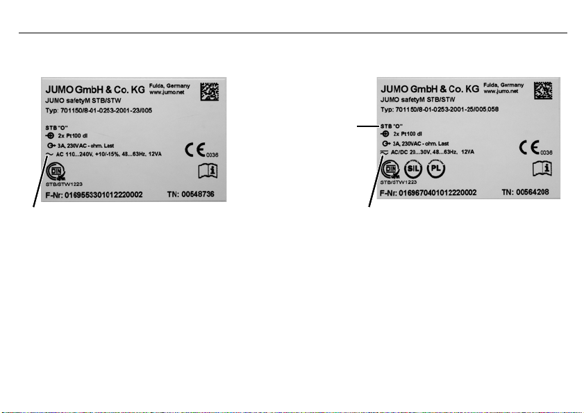
Symbol Meaning Explanation
Note This symbol is used to draw your attention to important information.
Caution This symbol is used when there is a risk of damage to equipment or data if the instructions are ig-
Danger This symbol is used when there is a risk of injury to persons if the instructions are ignored or not
Read This text contains important information and must always be read before work is continued. Han-
v Reference This symbol refers to further information in other manuals, chapters or sections.
1
abc
*
2014-05-01
Footnote Footnotes are remarks referring to specific points in the text marked with a superscript number.
Instructions
for action
nored or not followed correctly.
followed correctly.
dling the device in any way that is not described in the Operating Manual or that is expressly forbidden will jeopardize your warranty rights.
This symbol indicates that an action to be performed is described. The individual steps are marked
by an asterisk.
1 Brief description
11
2014-05-01
Voltage supply AC 110 to 240 V:
Voltage supply AC/DC20 to 30 V:
Switching behavior
2 Identifying the device version
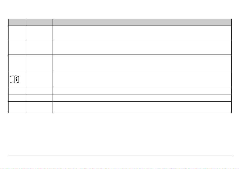
The type plate is affixed to the side of the device.
The voltage supply must correspond to the voltage given on the type plate!
2 Identifying the device version
12

Basic type
701150 Safety temperature limiters (STB) / monitors (STW) according to DIN EN 14597
Ver sion
8 Factory setting
9 Configured according to customer specifications
01 German (factory setting)
02 English
03 French
0251 Safety temperature monitor max. alarm (inverse, N/C contact)
0252 Safety temperature monitor min. alarm (direct, N/O contact)
0253 Safety temperature limiter max. alarm (inverse, N/C contact)
0254 Safety temperature limiter min. alarm (direct, N/O contact)
1003 1x Pt100 in 2-wire circuit
2001 2x Pt100 in 3-wire circuit (ex-factory)
2003 2x Pt100 in 2-wire circuit
2006 2x Pt1000 in 3-wire circuit
2037 2x W3Re-W25Re «D»
2039 2x Cu-CuNi «T»
2040 2x Fe-CuNi «J»
2041 2x Cu-CuNi «U»
2042 2x Fe-CuNi «L»
2043 2x NiCr-Ni «K»
Language
Switching behavior
Measuring input1 (programmable)
2014-05-01
2 Identifying the device version
13

2014-05-01
2044 2x Pt10Rh-Pt «S»
2045 2x Pt13Rh-Pt «R»
2046 2x Pt30Rh-Pt6Rh «B»
2048 2x NiCrSi-NiSi «N»
1053 1x 4 to 20 mA
2053 2x 4 to 20 mA
23 AC 110 to 240 V +10 % /-15 %, 48 to 63 Hz
25 20 to 30 V AC/DC, 48 to 63 Hz
701150 / 8 — 01 — 0253 — 2001 — 23 / 005 , 062
1. The first number on the measuring input means single probe «1“ or double probe «2“
2 Identifying the device version
Voltage supply
Analog output (configurable)
001 0 to 20 mA
005 4 to 20 mA (ex-factory)
040 0 to 10 V
070 2 to 10 V
Extra code
2.1 Scope of delivery
-JUMO safetyM STB/STW in the version ordered
— Operating Manual B701150.0
058 SIL and PL approval
062 GL approval
14
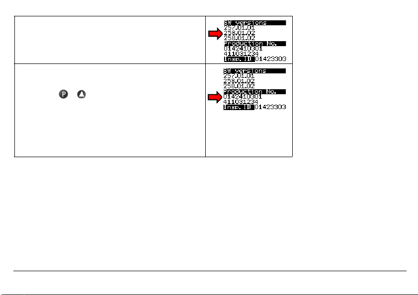
2.2 Device software versions
Diagnosis module version: 257.01.01
Analog channel 1 version: 258.01.02
Analog channel 2 version: 258.01.02
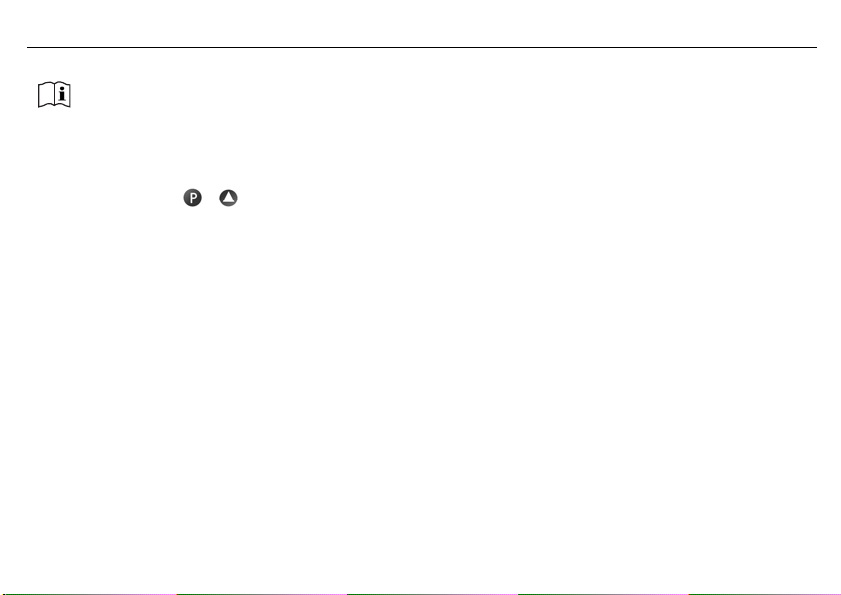
2.3 Serial number
The serial number is indicated on the device.
h Press the + keys
Construction:
The first 8 digits specify the serial number: 01424103
Digit 9 and 10 the production plant in Fulda: 01
Digit 11 (second line) the hardware version: 4
Digit 12 and 13 the year: 2011
Digit 14 and 15 the calendar week: 03
Digit 16 to 19 consecutive numbers: 1234
2.4 Service addresses
Phone support in Germany:
Telephone:+49 661 6003-9135
Fax: +49 661 6003-881899
Email: service@jumo.net
2014-05-01
Austria:
Telephone:+43 1 610610
Fax: +43 1 6106140
Email: info@jumo.at
Switzerland:
Telephone:+41 44 928 24 44
Fax: +41 44 928 24 48
Email: info@jumo.ch
2 Identifying the device version
15
2014-05-01
2 Identifying the device version
This operating manual is a translation of the German original manual.
It is valid for the following hardware and software versions:
Diagnosis module from version: 257.01.01
Analog channel 1 from version: 258.01.02
Analog channel 2 from version: 258.01.02
Hardware version: 0
16
h Press the + keys
Keep the operating manual in a place accessible to all users at all times.
All necessary settings are described in this Operating Manual.
Handling the device in any way that is not described in the Operating Manual or that is expressly forbidden will
jeopardize your warranty rights and may disable the safety function.
It is forbidden to access the inside of the device!
Repairs may only be performed by JUMO at the head office in Fulda.
Please contact the nearest subsidiary or the head office should you encounter any problems.
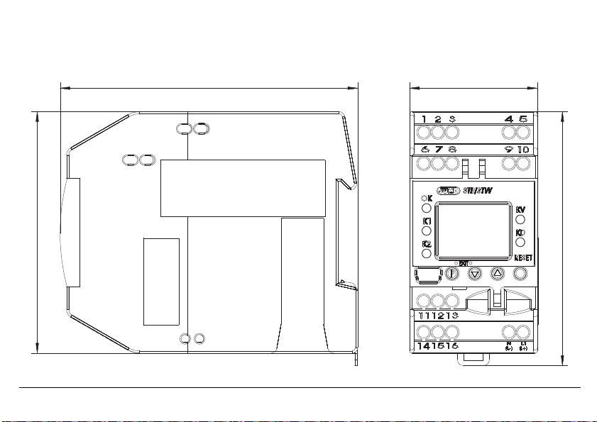
3 Installation
3.1 Dimensions
2014-05-01
3 Installation
17

2014-05-01
3.2 Installation location, DIN rail installation
The device is not suitable for use in potentially explosive atmospheres.
The device is hooked into a 35 mm DIN rail (EN 60715) from the front and
pushed down to engage.
The ambient conditions at the installation site must meet the requirements
v
specified in the technical data.
Chapter 8 «Technical data»
As far as possible, the installation site should be vibration-free to prevent the screw-connections from working loose.
a
The installation site should be free from aggressive media, e.g. acids and lyes, and, if possible, free from dust, flour or
a
other suspended matter in order to prevent the cooling slots from becoming clogged.
3.3 Close mounting
Observe a minimum spacing of 20 mm from the top and bottom.
a
1. To allow the release slot to be accessed with a screwdriver from below.
2. To allow the device to be swiveled up and unhooked from the DIN rail for removal.
Several devices may be mounted side by side without a gap.
a
3 Installation
18
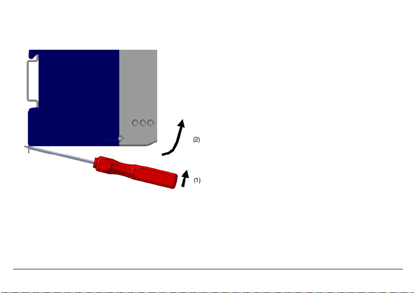
3.4 Dismantling
h Insert a screwdriver into the release lug from below and lift up (1).
h Simultaneously swivel the screwdriver and case up out of the DIN rail (2).
2014-05-01
3 Installation
19
2014-05-01
»
3700 V AC
»
3700 V AC
(1)
(2)
(4)
(3)
(5)
(8)
(6)
(7)
»
3700 V AC
50 V DC
»
3.5 Electrical isolation
3 Installation
20
(1) Analog inputs
(3) Binary input
(5) Setup interface
(6) Display
(7) Analog output
3.6 Use of the setup interface
— The setup interface USB is only designed for service use for a limited period, e.g. for transmitting setup data and during
— It is not suitable for operation in a fixed installation for an unlimited period as the monitoring function is switched off during
(8) Power supply
commissioning.
data transmission with the setup program.
(2) Relay output «Alarm»
(4) Relay output «Pre-alarm»

4 Electrical connection
4.1 Installation notes
Check that the safety temperature limiter is correctly installed for its application (temperature measurement) and is oper-
a
ated within the admissible system parameters.
The device is designed for installation in switch cabinets, machines/plants or systems.
a
Ensure that the customer’s fuse rating does not exceed 20 A.
Isolate the device at all poles prior to starting service or repair work.
a
All incoming and outgoing lines without a connection to the power supply network must be laid with shielded and
a
twisted lines. Connect the screen on the device side to ground.
Do not run input and output lines close to current-carrying components or cables.
a
Do not connect any additional consumers to the screw terminals for the device power supply.
a
The choice of cable, the installation and the electrical connection of the device must conform to the requirements of VDE
a
0100 «Regulations on the Installation of Power Circuits with Nominal Voltages below 1000 V» or the appropriate local
regulations.
Protect the relay circuit by suitable measures.
a
The maximum contact rating is 230 V/3 A (ohmic load).
The electromagnetic compatibility conforms to the standards and regulations cited in the technical data.
a
v Chapter 8 «Technical data»
During commissioning we recommend carrying out a trial run of the system until temperature switch-off at the set limit.
a
Only allow qualified electricians to carry out the electrical connection and the configuration settings until commissioning.
2014-05-01
4 Electrical connection
21

2014-05-01
4 Electrical connection
The approval according to DIN EN 14597 is only valid when the correct probe with DIN approval is set in the configuration level and also connected.
The limit value to be monitored must be within the admissible temperature range of the DIN probe.
v Chapter 8.12 «Probes for the operating medium air»
v Chapter 8.13 «Probes for the operating medium water and oil»
The monitoring function is deactivated during data transmission using the setup program.
v Chapter 12 «What to do, if …»
22
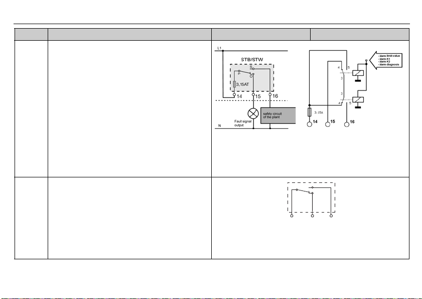
4.2 Connection diagram
Connection is carried out via screw terminals. Lead Admissible cross sec-
1 wire
fine-strand,
with core-end ferrule
2014-05-01
4 Electrical connection
tion
≤ 2.5 mm
≤ 1.5 mm
2
2
23
2014-05-01
A
Enter the lead resistance for RTD temperature probes in two-wire circuit when using greater line
lengths.
v Setup program: edit => analog inputs
4 Electrical connection
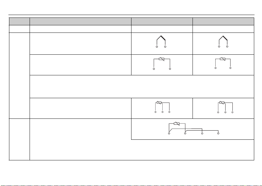
Legend Remark Screw terminals Screw terminals
1, 2 Analog input1 (E1) Analog input2 (E2)
Thermocouple/
double thermocouple
RTD temperature probe Pt100/Pt1000 in
2-wire circuit
RTD temperature probe Pt100/Pt1000
in three-wire circuit
RTD temperature probe Pt100 in
two-wire circuit, individual probe for both analog
inputs
Caution:
When only one probe (SIL2) is connected, the temperature limitation device
is reduced from SIL3 to SIL2. However, the internal 2-channel structure (1oo2D) in the device is still retained.
Both channels measure the same probe due to the simplified external circuit.
24
Legend Remark Screw terminals Screw terminals
4 to 20 mA
4 to 20 mA for both analog inputs
Caution:
When only one probe (SIL2) is connected, the temperature limitation device
is reduced from SIL3 to SIL2. However, the internal 2-channel structure (1oo2D) in the device is still retained.
Both channels measure the same current signal due to the simplified external circuit.
4 Binary input
Connection to a potential-free contact
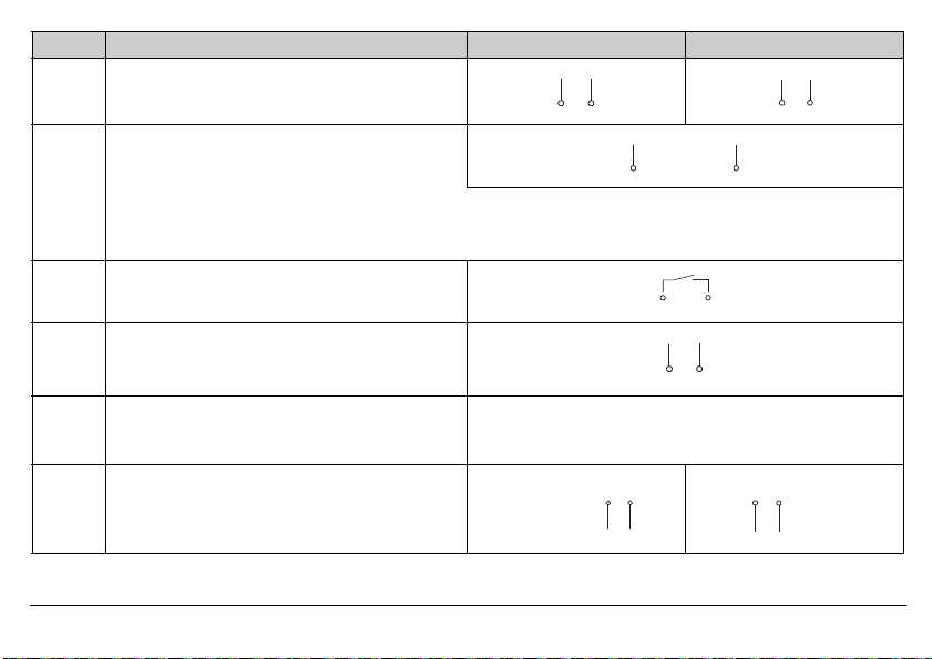
5 Analog output:
0 to 20 mA
4 to 20 mA (ex-factory)
0(2) to 10V
Caution
The analog output is not part of the safety func-
tion!
9 Voltage supply
2014-05-01
according to rating plate
AC:
L1 Line conductor
N Neutral
4 Electrical connection
DC:
(L+)
(L-)
25
2014-05-01
Legend Remark Screw terminals Screw terminals
10 Relay output «Alarm» (current-free state)
Relay (changeover contact element) with fuse cutout
4 Electrical connection
26
11 Relay output for pre-alarm (KV)
Changeover contact
Caution
The pre-alarm relay output is not part of the
safety function!
5 Commissioning the device
(1) (2) (3)
(4)
(5)
(6)
(7)
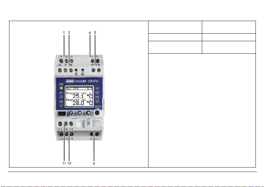
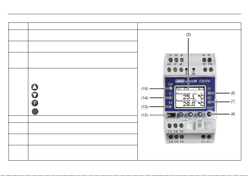
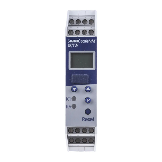
5.1 Display and operating elements
h Connect the voltage supply — a test routine will start during which all LEDS will flash and the display with background light-
ing will indicate white pixels for 2 seconds and black pixels for 2 seconds.
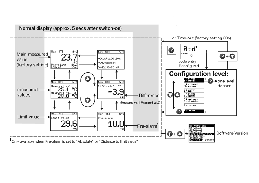
Once the test routine has been completed, the device will indicate the main measured value (factory set).
v If an alarm or error message appears, refer to Chapter 10 «Alarm messages».
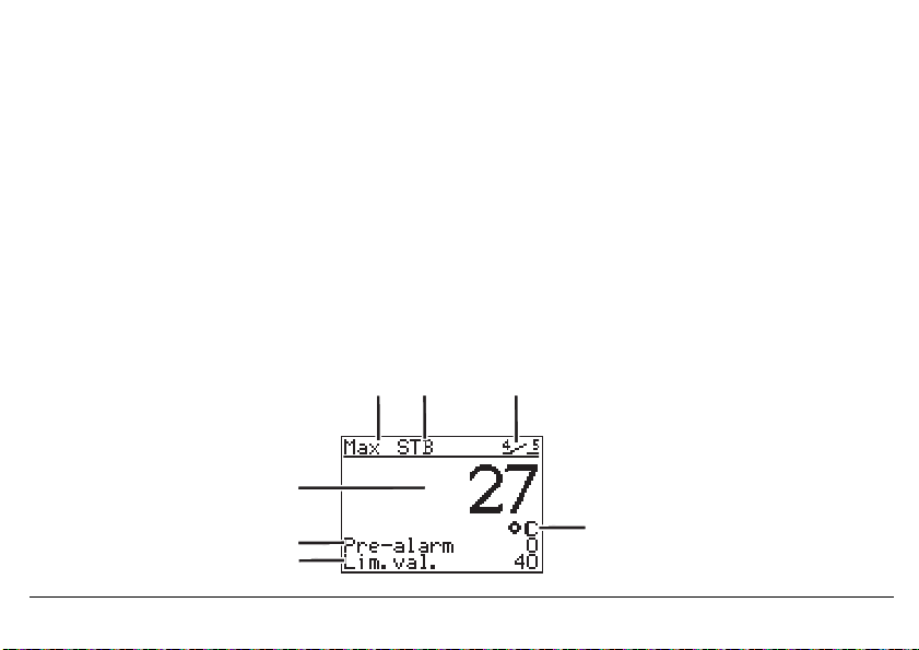
5.2 Setting the display after switch-on
v Chapter 7.6.4 «Normal display»
The screen is factory set to show the main measured value in German. The example shows the screen layout of a safety temperature limiter monitoring a maximum value of 29.6°C with a pre-alarm set to 9.9°C.
If the main measured value is within the hysteresis during «Power ON», the relay outputs «Pre-alarm» and «Alarm»
are deactivated.
1 Switching behavior 2 Device function
3 Binary input
7 Main measured value
6 Pre-alarm 4 Temperature unit
5 Limit value
2014-05-01
5 Commissioning the device
27
2014-05-01
Legend Remark
3LCD display
6 LED KV (yellow)
7 LED KD (yellow)
8Keys
12 Setup interface
13 LED K2 (red)
14 LED K1 (red)
15 LED OK
Black and white with background lighting 96 x 64 pixels
Is lit if the pre-alarm was triggered.
Is lit if the diagnosis processor has switched off a component.
(Can only be operated when the transparent hood is folded up)
Increase value / previous parameter
Reduce value / next parameter
Programming
RESET
Is lit for all errors.
Is lit for all errors.
Green: OK range
OFF: Error occurred
5 Commissioning the device
28
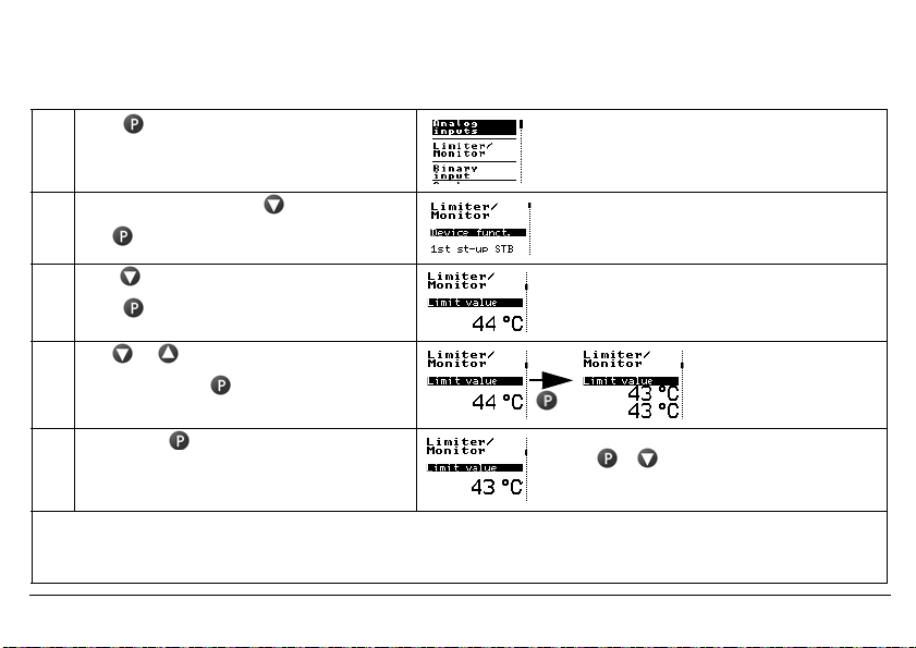
5.3 Selecting and editing parameters (plausibility inquiry for input values)
The values are displayed in the standard display.
Carry out steps 1 to 4 to edit a value, e.g. in this case, the limit value
1 Press The first menu item «Analog inputs» has a black
2 Select limiter/monitor with
Use to change to the submenu
3 Press 2x until the limit value appears
Press (limit value flashes)
background. The vertical line on the right shows
the current position.
4 Use or to set the desired value
Acknowledge with
(limit value is shown in duplicate)
5 Briefly press to confirm the value.
The value is applied and saved.
If no key is pressed, the device automatically returns to the standard display after 30 seconds (timeout) and the value
H
is not saved. The length of the timeout is configurable.
Use + to return to the standard display
or menu topic «Back» or
return automatically after a timeout
Limit value flashes in duplicate on the display as a
control.
v see operating overview on the first inner page of this manual.
2014-05-01
5 Commissioning the device
29
2014-05-01
5 Commissioning the device
30
5.4 Aborting edit
+ are used to abort editing and retain the previous value.
5.5 Alarm acknowledgement using the Reset key (only for temperature limiters STB)
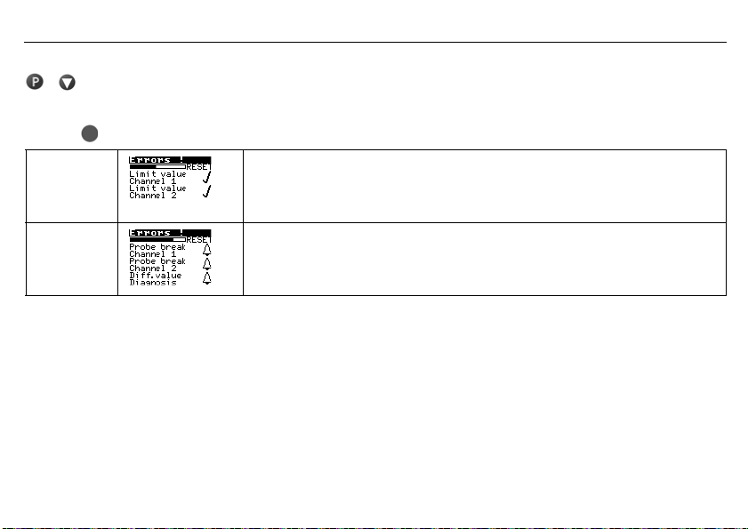
h Press key and hold down
Ticks appear
after the errors
A bell is
shown after
the error.
The alarm is no longer pending and is acknowledged as soon as the time bar has finished (3 seconds).
The alarm condition is still pending and cannot be acknowledged.
5.6 Alarm acknowledgement via binary input (only for temperature limiters STB)
The binary input can be configured so that, for example, alarms can be unlocked via a potential-free contact.
The function only reacts to the switching flank from the «open» to the «closed» state.
The contact then behaves in the same way as the «Reset» button.
v Chapter 7.4.1 «Function»
Loading…
- Структура 1oo2D – обеспечивает высокий стандарт безопасности процесса
- Упрощающий управление текстовый ЖК-дисплей с фоновой подсветкой
- Setup-Программа для конфигурирования и архивации через USB-Интерфейс
- Цифровой входной фильтр с задаваемой временной константой
- Предварительная тревога как абсолютное значение или как отступ от предельного значения
- Широкий диапазон электропитания AC 110 … 240 В +10 %/-15 % или AC/DC 20 … 30 В
- Может конфигурироваться как STB или STW
- 12 настраиваемых линеаризаций
- Внутренняя или внешняя Разблокировка
- Соответсвие DIN EN 14597, SIL, PL (Performance-Level)
- Допуска UL, GL в процессе получения
Описание
Применение предохранительного ограничителя температуры (STB) и предохранительного реле температуры (STW) позволяет заблаговременно распознать и предотвратить опасности, которые могут привести к увечью людей, причинению ущерба окружающей среде или разрушению производственных установок и промежуточных изделий.
Главной задачей приборов является надежный контроль теплотехнических процессов и приведение установок в безопасное рабочее состояние при неисправностях. Измеряемое значение на аналоговом входе может быть получено с разных датчиков или через унифицированные сигналы.
Устройство контроля предельного значения имеет сигнализацию посредством светодиодов К1 и К2 (красный) для каждого канала, а встроенное реле тревоги приводит установку в безопасное состояние (в диапазоне тревог).
Высокие требования DIN EN 61508 как и DIN EN ISO 13849 выполняются благодаря концепции прибора, конструкция которого (1oo2D: 2-канальная структура с диагностическим каналом) гарантирует надежное обнаружение ошибок, поэтому может применяться также и в сферах, требующих соблюдения директивы по машиностроению 2006/42/ЕС.
- Аналогичные товары
Вся информация на сайте о товарах и ценах носит справочный характер и не является публичной офертой. Производитель оставляет за собой право изменять характеристики товара, его внешний вид и комплектность без предварительного уведомления продавца
-
Contents
-
Table of Contents
-
Bookmarks
Quick Links
JUMO safetyM TB/TW
Temperature limiter, temperature
monitor
nach DIN EN 14597
B 70.1160.0
Operating Instructions
2011-12-31
Related Manuals for JUMO safetyM TB/TW
Summary of Contents for JUMO safetyM TB/TW
-
Page 1
JUMO safetyM TB/TW Temperature limiter, temperature monitor nach DIN EN 14597 B 70.1160.0 Operating Instructions 2011-12-31… -
Page 2: Overview Of Operation
Overview of operation Normal display (appr ox. 5 secs after switch-on) Only available when C111=24 when when > 2 seconds Measured Limit value C116 = 0 C116 = 5 value (factory setting) Parameter level AL, VA, ALD, DF when Measured C116 = 1 Differential >…
-
Page 3: Table Of Contents
Contents Overview of operation …………2 Brief description .
-
Page 4
C111 Analog inputs …………20 C112 Setting for a double thermocouple . -
Page 5
Contents Probes for operation in air ……….. . . 36 Probes for operation in water and oil . -
Page 6: Brief Description
2011-12-31 1 Brief description Brief description Temperature limiters (TB) and temperature monitors (TW) are used to monitor thermal processes in systems, to signal whenever the measurement exceeds or falls below an adjustable limit value. This limit infringement is indicated by built-in LED K1 and the fitted relay switches the system to a safe operating state (alarm range).
-
Page 7: Identifying The Instrument Version
Phone: +41 44 928 24 44 Phone: +49 661 6003-300 or -653 or -899 Fax: +43 1 6106140 Fax: +41 44 928 24 48 Fax: +49 661 6003-881729 E-mail: info@jumo.at E-mail: info@jumo.ch E-mail: service@jumo.net 2011-12-31 2 Identifying the instrument version…
-
Page 8
2011-12-31 2 Identifying the instrument version Basic type 701160 Temperature limiter (TB) / temperature monitor (TW) Version factory setting configuration to customer specification Switching action 0151 Inverse temperature monitor 0152 Direct temperature monitor 0153 Inverse temperature limiter 0154 Direct temperature limiter Measurement input (programmable) Pt100 in 3-wire circuit Pt100 in 2-wire circuit… -
Page 9: Scope Of Delivery
001 — factory setting Scope of delivery JUMO safetyM TB/TW in the ordered version 1 Operating Instructions 701160.0 All the required settings are described in the current operating instructions. Carrying out manipulations not described, or expressly forbidden in the operating instructions, will put your warranty at risk! If you have any problems, please contact the nearest subsidiary or the head office.
-
Page 10: Mounting And Removal
2011-12-31 3 Mounting and removal Mounting and removal The instrument is clipped onto a 35 mm DIN rail (EN 60715) from the front. Insert a screwdriver into the release slot, push towards the instrument and swing it downward, out of the DIN rail.
-
Page 11: Mounting Location
Mounting location Preferably vibration-free, so that screw terminals cannot work loose! Free from aggressive media, such as strong acids and caustic solutions and preferably free from dust and powder or other suspended matter, so that ventilation slots cannot get blocked up! Close mounting Maintain at least 10 cm of space at the top, so that the release slot can be accessed with a screwdriver from above.
-
Page 12: Electrical Connection
2011-12-31 4 Electrical connection Electrical connection Installation notes The instrument is fitted with electronic components that can be destroyed by electrostatic discharge. It is therefore important during mounting, maintenance and servicing that personnel working on the instrument have adequate electrostatic discharge protection. All incoming and outgoing lines without a connection to the mains supply must be laid with shielded and twisted cables.
-
Page 13: Connection Diagram
Connection diagram Screw terminals are used for connecting strands with a cross-section of 0.2 to 2.5mm DC supply: AC supply: 2011-12-31 4 Electrical connection…
-
Page 14
2011-12-31 4 Electrical connection Supply as on nameplate L1 External conductor N Neutral conductor Analog inputs Thermocouple / double thermocouple (evaluated for temp. Limiter) Resistance thermometer in 2-wire circuit (evaluated for temp. Limiter) or KTY11-6 PTC in 2-wire circuit Lead resistance must be entered for resistance thermometers in 2-wire circuit with longer cable lengths. -
Page 15
Analog inputs 0 to 20 mA 4 to 20 mA (evaluated for temp. Limiter) 0(2) to 10 V Binary input for connection to floating contact Binary output 24 V DC / 20 mA (short-circuit proof) Relay output Relay with safety fuse for pole contact Ö… -
Page 16: Commissioning The Instrument
2011-12-31 5 Commissioning the instrument Commissioning the instrument Displays and controls Apply the supply voltage, all segments light up four seconds long (for testing the segments). If everything is properly connected on the instrument, it will display the limit value, measured value or warning alarm, depending on the configuration.
-
Page 17: Display After Switch-On
Display after switch-on The value to be displayed is adjustable, as in Chapter 7.6 “C116 Display after switch-on” Selecting and editing parameters (plausibility requirement for input values) Values are displayed in the normal display. To edit a value, here, for example, the AL limit, perform steps 1 — 4 Press for longer than 2 secs 1st value in the parameter level appears…
-
Page 18: Canceling Editing
2011-12-31 5 Commissioning the instrument Canceling editing will cancel editing, the original value is retained. Acknowledging alarms (for temperature limiters (TB) only) Requirement: C114 = 0 or C114 = 1 Press (Reset) with a suitable tool…
-
Page 19
2011-12-31 5 Commissioning the instrument… -
Page 20: Parameter Level
2011-12-31 6 Parameter level Parameter level This level is where to find the parameters AL, VA, ALD and DF, which are freely accessible to operating personnel at the factory. In normal display, press for longer than 2 secs and AL will appear. This level can be inhibited by the setup program.
-
Page 21: Configuration Level
Configuration level All the configuration level parameters C111 — C122 are listed in the table below. Parameters that are not required are automatically blanked out. In normal display, press for longer than 2 secs and AL will appear. Press again for longer than 2 secs and C111 will appear. Each time you press , you move to the next parameter.
-
Page 22: C111 Analog Inputs
2011-12-31 7 Configuration level C111 Analog inputs Setting range for AL: Limits for Analog input Comment (can be restricted via overrange/ setup) underrange Pt 100 in 3-wire circuit -1999 to +9999°C -205°C/ +855°C EN 60751 Pt 1000 in 3-wire circuit -1999 to +9999°C -205°C/ +855°C EN 60751…
-
Page 23
Setting range for AL: Limits for Analog input Comment (can be restricted via overrange/ setup) underrange If the system is in the OK range, the relay is active and LED K1 shows green. If the system leaves the OK range, the relay switches off and LED K1 shows red. 2011-12-31 7 Configuration level… -
Page 24
2011-12-31 7 Configuration level Setting range for AL: Limits for Analog input Comment (can be restricted via overrange/ setup) underrange W3Re-W25Re D Thermocouple -1999 to +9999°C to +2500°C Cu-CuNi T Thermocouple EN 60584 -1999 to +9999°C -205 to +405°C Fe-CuNi J Thermocouple EN 60584 -1999 to +9999°C -205 to +1205°C… -
Page 25: C112 Setting For A Double Thermocouple
C112 Setting for a double thermocouple Double thermocouple Comment sensor short circuit not detected! only available for C111 from 037 to 048 Chapter 7.1 “C111 Analog inputs” Can detect a sensor short circuit C113 Unit, decimal place Unit, decimal place Comment °C, no decimal place When the unit changes to °F, the measurement is…
-
Page 26: C115 Switching Action
2011-12-31 7 Configuration level C115 Switching action Switching Comment action inverse If limit value AL is exceeded, the fitted relay switches OFF. LED K1 shows red and the limit flashes in the display. The temperature limiter remains in this state, even if the measured value falls below limit AL. Only when a tool has been used to press the «Reset»…
-
Page 27
Switching Comment action direct If the value falls below limit AL, the fitted relay switches OFF. LED K1 shows red and the limit flashes in the display. The temperature limiter remains in this state, even if the measured value rises above limit AL. -
Page 28: C116 Display After Switch-On
2011-12-31 7 Configuration level C116 Display after switch-on Normal display Comment Limit value Chapter “Overview of operation” Measured value Warning alarm Limit for the differential Can only be set when C111 = 24 (differential measurement) is set. Differential Measured value 2 C117 Binary input function Binary input function Comment…
-
Page 29: C118 Display Switch-Off After Timeout
C118 Display switch-off after timeout Display switch off Comment inactive Display is permanently switched on. active Display switches off after a timeout and re-appears, as soon as a key is pressed. C119 Warning alarm function The warning alarm is indicated via LED KV and is output simultaneously at the binary output. The switching action can be configured as an absolute value or as an interval to the limit value (relative).
-
Page 30: Scl, Sch, Al Lo, Al Hi, Offs, Hyst1, Hyst2
2011-12-31 7 Configuration level 7.10 SCL, SCH, AL LO, AL HI, OFFS, HYST1, HYST2 Function Comment Value range (factory setting in bold) lower limit of standard signal only when C111 set with 52, 53, 63, 71 -1999 to 0 to 9999 upper limit of standard signal only when C111 set with 52, 53, 63, 71 -1999 to 100 to 9999…
-
Page 31: C 121 Count For Relay Switching Operations
7.12 C 121 Count for relay switching operations Value range Meaning (factory setting in bold) Count for relay switching operations 0 to 9999 This is the actual counted amount of switching operations for the relay. If the limit-value set under C120 (factory setting 1000) is reached, error message 0001 is displayed and the relay is deenergized.
-
Page 32: Technical Data
2011-12-31 8 Technical data Technical data Analog inputs Resistance thermometers Designation Measuring range Accuracy Pt 100 EN 60751 -200 to +850°C 0.1% KTY11-6 -50 to +150 °C Pt 1000 EN 60751 -200 to +850°C 0.1% Connection circuit 2-wire, 3-wire circuits Sampling 210 ms Input filter…
-
Page 33
NiCrSi-NiSi N EN 60584 -100 to +1300°C 0.4% Pt10Rh-Pt S EN 60584 0 to +1768°C 0.4% Pt13Rh-Pt R EN 60584 0 to +1768°C 0.4% Pt13Rh-Pt6Rh B EN 60584 300 to 1820°C 0.4% W3Re-W25Re D 0 to +2495°C 0.4% Cold junction Pt 100, internal Cold junction accuracy ±… -
Page 34: Measuring Circuit Monitoring
2011-12-31 8 Technical data Measuring circuit monitoring RTD temperature probe Twin thermocouples Thermocouples Current 0 to 20 mA, 4 to 20mA and KTY11-6 Voltage 0 to 10 V, 2 to 10 V Overrange is detected underrange LEDs K1 and KV light up; «9999» flashes in the display Probe lead is detected…
-
Page 35: Binary Input
Binary input Connection Function 1 floating contact Configurable unlocking, keyboard inhibit, level inhibit Binary outputs 1 relay 10,0000 operations at a contact rating of 3A/230V, 50Hz resistive load Contact protection circuit: safety fuse 3.15AT, installed in the pole contact arm within the instrument 1 Binary output 24 V DC / 20mA logic signal, short-circuit proof Supply…
-
Page 36: Electrical Safety
2011-12-31 8 Technical data Electrical safety Clearances / creep paths ≥ / ≥ Mains to electronic components and probe 6 mm 8 mm ≥ / ≥ Mains to the relay 6 mm 8 mm ≥ / ≥ Relay to electronic components and probe 6 mm 8 mm Electrical safety…
-
Page 37: Housing
Housing Material polyamide (PA 6.6) Screw terminal 0.2 to 2.5mm screw terminal Mounting on 35mm x 7.5mm DIN rail to EN 60715 Operating position vertical Weight approx. 160g Protection IP 20 to EN 60529 8.10 Approvals/Marks approval Inspection authority Certificate/Inspection inspection basics valid for marks…
-
Page 38: Din-Approved Probes
2011-12-31 9 DIN-approved probes DIN-approved probes Probes for operation in air Note: Because of the high response accuracy, the use of thermowells (pockets) is not admissible. Actual type designation Old type Probe type Temperature range Nom. length mm rocess connection designation RTD temperature probe Data Sheet 90.2006 902006/65-228-1003-1-15-500-668/000…
-
Page 39: Probes For Operation In Water And Oil
901006/66-953-1046-6-250-668/000 90.027 1 x PT30Rh-PT6Rh, Typ „B“ 600 … 1500°C 901006/66-953-1046-6-355-668/000 90.028 901006/66-953-1046-6-500-668/000 90.029 901006/66-953-2046-6-250-668/000 90-D-027 2 x PT30Rh-PT6Rh, Typ „B“ 600 … 1500°C 901006/66-953-2046-6-355-668/000 90-D-028 901006/66-953-2046-6-500-668/000 90-D-029 Probes for operation in water and oil Note: Because of the high response accuracy, the use of thermowells (pockets) is not admissible. Actual type designation Old type Probe type…
-
Page 40
2011-12-31 9 DIN-approved probes Note: Because of the high response accuracy, only use thermowells (pockets) that are included in the scope of delivery. Actual type designation Old type Probe type Temperature range Nom. length mm rocess connection designation RTD temperature probe Data Sheet 90.2006 902006/53-505-2003-1-12-190-815/000 90D239-F03 2 x Pt100… -
Page 41: Probes For Operation In Air, Water And Oil
Probes for operation in air, water and oil Note: Because of the high response accuracy, the use of thermowells (pockets) is not admissible. Actual type designation Old type Probe type Temperature range Install. length mm rocess connection designation RTD temperature probe Data Sheet 90.2006 90.2006/10-390-1003-1-8-250-104/000 90.210-F95 1 x Pt100…
-
Page 42
2011-12-31 9 DIN-approved probes… -
Page 43: Setup Program
Setup program This program and the interface with adapter can be supplied as accessories. They offer the user the following advantages: easy and convenient parameterization and archiving from a PC simple duplication of parameters for instruments of the same type 10.1 Hardware and software requirements PC Pentium III or above 128 MB RAM, 16 MB free space on hard disk…
-
Page 44: Activating The Access Code
2011-12-31 10 Setup program 10.3 Activating the access code The factory setting is for no level inhibit to be active in the instrument. The access code can only be activated by the Setup program. In the Setup program, enter a different value to «0» for the access code and transfer it to the instrument Now the parameter level and the configuration level on the device are only accessible with the correct access code.
-
Page 45: Alarm Messages
Alarm messages The following alarm messages can be shown in alternation with the temperature display: Alarm display Cause Remedy 9999 flashes Gone above measured value Check probe and connecting cable for damage or The measured value is too large, is short-circuit outside the range, or a probe has Chapter 4.2 “Connection diagram”…
-
Page 46: Error Messages
-999 and is thus outside the 3-digit display range. If that does not help, send the instrument in 0004 Calibration constant The instrument must be returned to JUMO for repair. Send the instrument in Chapter 2.1 “Service addresses” 0005 Configuration data…
-
Page 47
0008 reserved 0009 Calibration data checksum The instrument must be returned to JUMO for repair. Send the instrument in 0010 Configuration data checksum Chapter 2.1 “Service addresses” 0011 Register error 0012 RAM error 0013 ROM error 0014 Program run error occurred… -
Page 48: What If
2011-12-31 13 What if… What if… Description Cause Remedy This appears The Setup program is transferring data. Wait for data transmission The monitoring function switches off briefly display: during data transmission and the instrument re- starts. The measurement in the The instrument is in the alarm range Press twice and check the limit value.
-
Page 49
Measure terminals 9 and 12 of the relay with a continuity tester when LED K1 is off The instrument must be returned to JUMO for repair. Chapter 2.1 “Service addresses” Double LED lit (green and Internal system error… -
Page 50
2011-12-31 13 What if… -
Page 52
JUMO GmbH & Co. KG JUMO Instrument Co. Ltd. JUMO Process Control, Inc. Street address: JUMO House 8 Technology Boulevard Moritz-Juchheim-Straße 1 Temple Bank, Riverway Canastota, NY 13032, USA 36039 Fulda, Germany Harlow — Essex CM20 2DY, UK Phone: 315-697-5866…
Page 1 — Operating Manual
/00564764JUMO safetyM STB/STWSafety temperature limiter, safety temperature monitor according to DIN EN 145972014-05-01B 701150.0Operating Manual(tran
Page 2 — Operating overview
1 Brief description2014-05-01101 Brief descriptionThe safety temperature limiter (STB) and the safety temperature monitor (STW) are used to reliably d
Page 3
9 Setup program2014-05-011009.3 Forgotten the code?If you forget the code, it can be read out via the USB interface and the setup program.h Perform a
Page 4
10 Alarm messages1012014-05-0110 Alarm messagesThey can appear as follows:Alarm display Cause Remedy5 flashing horizontal lines: Measured value errorN
Page 5
11 Error messages2014-05-0110211 Error messagesThese error messages are displayed one below the other.Error display (Err) Origin Cause/remedyInternal
Page 6
11 Error messages1032014-05-01Measured value missing Internal When the error status «Measured value» is signaled by the channelthen the diag
Page 7
11 Error messages2014-05-01104Watchdog1Internal A watchdog reset has occurred.Acknowledgement is possible.Overvoltage1Internal The uncontrolled second
Page 8
11 Error messages1052014-05-01Diagnosis functionFLASH defective1Internal An error was detected during the cyclic memory test of the ROM.RAM defective1
Page 9
11 Error messages2014-05-01106Footnote 1 If the error cannot be acknowledged despite repeated switching off and on,the device must be repaired by JUMO
Page 10 — 1 Brief description
12 What to do, if …1072014-05-0112 What to do, if …Description Cause RemedyThe following appears inthe display:Setup program transmits data.The m
Page 11
12 What to do, if …2014-05-01108Description Cause Remedy… relay output «Alarm»between terminal 14 and16 is not closed althoughthe LED OK
Page 12 — 2014-05-01
13 Information for devices with extra code 062 GL1092014-05-0113 Information for devices with extra code 062 GLThe following information supplements
Page 13
1 Brief description112014-05-011.3 Safety informationSymbol Meaning ExplanationHNote This symbol is used to draw your attention to important informati
Page 14 — 2.1 Scope of delivery
13 Information for devices with extra code 062 GL2014-05-01110HFor service work, the device must be returned to the head office.According to recommend
Page 16
14 Output behavior2014-05-01112Operating status Relay output alarm Relay output pre-alarm KVAnalog outputInitializationInitialization phase after main
Page 17 — 3 Installation
14 Output behavior1132014-05-01After probe break, probe short circuit (STW) Monitoring of the limitvalue activev Chapter 7.3.2Pre-alarm moni-toring ac
Page 18
14 Output behavior2014-05-01114Differential – Alarm inactive again (STB function) Inactive Unlocking possiblePre-alarm moni-toring activev Chapter7.3.
Page 19
14 Output behavior1152014-05-01
Page 20 — 3.5 Electrical isolation
JUMO GmbH & Co. KG JUMO Instrument Co. Ltd. JUMO Process Control, Inc.Street address:Moritz-Juchheim-Straße 136039 Fulda, GermanyDelivery address:
Page 21 — 4 Electrical connection
2 Identifying the device version2014-05-01122 Identifying the device versionThe type plate is affixed to the side of the device.AThe voltage supply m
Page 22
2 Identifying the device version132014-05-01Basic type701150 Safety temperature limiters (STB) / monitors (STW) according to DIN EN 14597Version8 Fact
Page 23 — ≤ 1.5 mm
2 Identifying the device version2014-05-01141. The first number on the measuring input means single probe «1“ or double probe «2“2.1 Scope o
Page 24
2 Identifying the device version152014-05-012.2 Device software versionsDiagnosis module version: 257.01.01 Analog channel 1 version: 258.01.02Analo
Page 25
2 Identifying the device version2014-05-0116This operating manual is a translation of the German original manual.It is valid for the following hardwar
Page 27 — 5 Commissioning the device
3 Installation2014-05-01183.2 Installation location, DIN rail installation3.3 Close mountingVThe device is not suitable for use in potentially explosi
Page 28
3 Installation192014-05-013.4 Dismantlingh Insert a screwdriver into the release lug from below and lift up (1).h Simultaneously swivel the screwdrive
Page 30
3 Installation2014-05-01203.5 Electrical isolation3.6 Use of the setup interface- The setup interface USB is only designed for service use for a limit
Page 31
4 Electrical connection212014-05-014 Electrical connection4.1 Installation notesaCheck that the safety temperature limiter is correctly installed for
Page 32 — 6 Safety Manual
4 Electrical connection2014-05-0122AThe approval according to DIN EN 14597 is only valid when the correct probe with DIN approval is set in the config
Page 33
4 Electrical connection232014-05-014.2 Connection diagramConnection is carried out via screw terminals. Lead Admissible cross sec-tion1 wire≤ 2.5 mm2f
Page 34
4 Electrical connection2014-05-0124Legend Remark Screw terminals Screw terminals1, 2 Analog input1 (E1) Analog input2 (E2)Thermocouple/double thermoco
Page 35
4 Electrical connection252014-05-014 to 20 mAV4 to 20 mA for both analog inputsCaution:When only one probe (SIL2) is connected, the temperature limita
Page 36
4 Electrical connection2014-05-012610 Relay output «Alarm» (current-free state)Relay (changeover contact element) with fuse cut-out11 Relay
Page 37
5 Commissioning the device272014-05-015 Commissioning the device5.1 Display and operating elementsh Connect the voltage supply — a test routine will
Page 38
5 Commissioning the device2014-05-0128Legend Remark3LCD displayBlack and white with background lighting 96 x 64 pixels6 LED KV (yellow) Is lit if the
Page 39 — Δangerous Υndetect: λ
5 Commissioning the device292014-05-015.3 Selecting and editing parameters (plausibility inquiry for input values)The values are displayed in the stan
Page 40
InhaltOperating overview . . . . . . . . . . . . . . . . . . . . . . . . . . . . . . . . . . . . . . . . . . . . . . . . . . . . . . . . . . . 21 Brie
Page 41
5 Commissioning the device2014-05-01305.4 Aborting edit + are used to abort editing and retain the previous value.5.5 Alarm acknowledgement using th
Page 42
5 Commissioning the device312014-05-015.7 Lead sealing the deviceThe device settings must not change under operating conditions. A lead-sealed, transp
Page 43
6 Safety Manual2014-05-01326 Safety Manual6.1 Brief descriptionThe safety temperature limiter (STB) and safety temperature monitor (STW) enable early
Page 44
6 Safety Manual332014-05-016.3 Safety temperature limiter (STB)The safety temperature limiter is a device that is permanently locked after responding.
Page 45 — ≥99 % SIL3 SIL4 SIL4
6 Safety Manual2014-05-0134Automatic Electrical Control and Regulating Devices for Household Use and Similar Applications Parts 2-9: Special Re-quirem
Page 46
6 Safety Manual352014-05-01Important information:Variants 1 to 4 were evaluated with JUMO probes according to data sheets 901006 and 902006. For varia
Page 47
6 Safety Manual2014-05-0136The possibility to connect passive sensors such as double thermocouples, Pt100 sensors, or Pt1000 sensors means that thesen
Page 48 — ≥ 60 % PL e: ≥ 62 years DC
6 Safety Manual372014-05-016.7 Standards and definitions6.7.1 Terms and abbreviations acc. to DIN EN 14597Abbreviation ExplanationType 2 Mode of opera
Page 49
6 Safety Manual2014-05-01386.7.2 Terms and abbreviations acc. to DIN EN 61 508 and DIN EN 61 511.Name DescriptionActuator Part of a safety-related sys
Page 50
6 Safety Manual392014-05-01Safety function A function that is performed by an E / E / PE safety-related system, safety-related system based on some ot
Page 51
Inhalt5.3 Selecting and editing parameters (plausibility inquiry for input values) . . . . . . . . . . . . . . . . . . . . . . . . .295.4 Aborting edi
Page 52
6 Safety Manual2014-05-0140Lambda: λSURate of undetected safe failures per hourBPCS Basic Process Control SystemDC Diagnostic CoverageFIT Failures In
Page 53
6 Safety Manual412014-05-016.8 Safety instrumented parameters related to the temperature monitoring unit The following parameters were calculated by m
Page 54
6 Safety Manual2014-05-01426.8.2 Failure rates and SFF for 701150…25 (AC/DC 24 V)Important information:Variants 1 to 4 were evaluated with JUMO prob
Page 55
6 Safety Manual432014-05-016.9 Determining the Safety Integrity Level (SIL)The achievable Safety Integrity Level is determined by the following safety
Page 56
6 Safety Manual2014-05-0144Table Low Demand PFDThe sensor, logic unit, and actuator together form a safety-related system that performs a safety funct
Page 57
6 Safety Manual452014-05-016.9.1 Safety integrity of the hardwareAccording to DIN EN 61 508, a distinction must be made between systems of type A and
Page 58
6 Safety Manual2014-05-01466.9.2 Safety-relevant system propertiesDevice versions differ in the following architectures:The evaluation unit from 70115
Page 59
6 Safety Manual472014-05-01Safety feature Requirement / commentSILThe sensor system is included in the SIL evaluation. SIL2 SIL3Operating mode concern
Page 60
6 Safety Manual2014-05-01486.10 Determining the achieved Performance Level PLThe following safety-related parameters are required to determine the Per
Page 61
6 Safety Manual492014-05-01AOPD Active Opto-Electronic Protective Device (e.g. light barrier) Appendix HB, 1, 2, 3, 4 Description for the categories T
Page 62
Inhalt6.10.1 Terms and abbreviations acc. to DIN EN ISO 13849 . . . . . . . . . . . . . . . . . . . . . . . . . . . . . . . . . . . . . . . . . . . .
Page 63
6 Safety Manual2014-05-0150M Motor Appendix IMTTF Mean Time To Failure Appendix CMTTFcMean time to critical failure 3.1.25MTTFd Mean time to dangerous
Page 64
6 Safety Manual512014-05-016.11 Connection possibilities of the sensors (PL)The JUMO safetyM STB/STW 701150 evaluation device structure is basically i
Page 65
6 Safety Manual2014-05-0152Important information:Variants 1 to 4 were evaluated with JUMO probes according to data sheets 901006 and 902006. For varia
Page 66
6 Safety Manual532014-05-016.11.1 Calculations DIN EN ISO 13849-1 Performance Level — low voltage 230 V6.11.2 Calculations DIN EN ISO 13849-1 Performa
Page 67
6 Safety Manual2014-05-01546.11.3 Contribution to risk minimization through the control systemThe objective of compliance with the overall draft proce
Page 68
6 Safety Manual552014-05-01Schematic representation of a combination of safety-related parts of controls for processing a typical safety functionI Inp
Page 69
6 Safety Manual2014-05-01566.12 Evaluating the achieved Performance Level PL and the relationship to the SILFor application in this part of DIN EN ISO
Page 70 — 7 Configuration level
6 Safety Manual572014-05-01Relationship between the categories DCavg, MTTFd of each channel and PLPL Performance Level1MTTFd of each channel = low2MTT
Page 71
6 Safety Manual2014-05-0158The diagram above shows the different possible combinations for assessing the category with DCavg (horizontal axis) and the
Page 72
6 Safety Manual592014-05-016.13 Other applicable device documentationFor temperature monitoring unit 701150 the measures, values, and requirements spe
Page 73
Inhalt7.2.11 Filter time 2 . . . . . . . . . . . . . . . . . . . . . . . . . . . . . . . . . . . . . . . . . . . . . . . . . . . . . . . . . . . . .
Page 74
6 Safety Manual2014-05-0160- Seals of terminal heads and cable ducts- Interruptions due to «knocking» on the thermometer/measuring insert Si
Page 75
6 Safety Manual612014-05-016.16 Certificates
Page 76
6 Safety Manual2014-05-0162
Page 77
6 Safety Manual632014-05-01
Page 78
6 Safety Manual2014-05-0164
Page 79
6 Safety Manual652014-05-01
Page 80
6 Safety Manual2014-05-0166
Page 81
6 Safety Manual672014-05-01
Page 82
6 Safety Manual2014-05-0168CERTIFICATE OF COMPLIANCE Certificate Number20120613-E325456 Report ReferenceE325456-20120611 Issue Date2012-JUNE-13 Willia
Page 83
6 Safety Manual692014-05-01
Page 84
Inhalt7.6.4 Normal display . . . . . . . . . . . . . . . . . . . . . . . . . . . . . . . . . . . . . . . . . . . . . . . . . . . . . . . . . . . . .
Page 85
7 Configuration level2014-05-01707 Configuration level7.1 Navigation principleAll the parameters are freely accessible at the factory, but they can be
Page 86
7 Configuration level712014-05-017.2 Analog inputsk Factory setting7.2.1 ConnectionCommentTwo sensors This setting is provided for dual probes or for
Page 87
7 Configuration level2014-05-0172k Factory setting7.2.2 Sensor type 1For analog input 1CommentSetting range for limit value:(can be restricted via the
Page 88 — 8 Technical data
7 Configuration level732014-05-01Parameter CommentValue range(factory-setting in bold)7.2.3 Offset 1Using Offset1, a measured value at the analog inpu
Page 89
7 Configuration level2014-05-0174k Factory setting7.2.8 Sensor type 2For analog input2CommentSetting range for limit value:(can be restricted via the
Page 90
7 Configuration level752014-05-01Parameter CommentValue range(factory-setting in bold)7.2.9 Offset 2Using Offset2, a measured value at the analog inpu
Page 91
7 Configuration level2014-05-01767.3 Limiter/monitorParameter CommentValue range(factory-setting in bold)7.3.1 Device functionSafety temperature limit
Page 92
7 Configuration level772014-05-017.3.2 Switching behaviorMin. alarm:If the measured value falls below the limit value, the alarm relay output switches
Page 93
7 Configuration level2014-05-0178Max. alarm:If the measured value exceeds the limit value, the alarm relay output switches OFF. The LEDs K1 and K2 lig
Page 94
7 Configuration level792014-05-017.3.3 Limit value, hysteresisLimit value alarm:If this value is exceeded or not reached, this affects the alarm relay
Page 95
Inhalt8.14 Probes for the operating medium water, oil and air . . . . . . . . . . . . . . . . . . . . . . . . . . . . . . . . . . . . . . . .989 Setup
Page 96
7 Configuration level2014-05-0180The admissible limits for DIN authorized probes:v Chapter 8.12 “Probes for the operating medium air” andv Chapter 8.1
Page 97
7 Configuration level812014-05-017.4 Binary inputk Factory settingParameter CommentValue range(factory-setting in bold)7.4.1 FunctionThis sets the fun
Page 98
7 Configuration level2014-05-01827.5 Analog outputParameter CommentValue range(factory-setting in bold)7.5.1 FunctionHere, the measured value that is
Page 99
7 Configuration level832014-05-017.5.5 Error signalIf, for the measured value 1 or 2, the value is exceeded, not reached, or a diagnostic error occurs
Page 100 — read-out from device
7 Configuration level2014-05-01847.5.6 Behavior when leaving the scaling rangeThe standard signal range of the analog output is limited as follows acc
Page 101 — 10 Alarm messages
7 Configuration level852014-05-017.6 Display/operationParameter CommentValue range(factory-setting in bold)7.6.1 LanguageGerman German, English, Frenc
Page 102 — 11 Error messages
7 Configuration level2014-05-01867.6.5 ContrastScreen contrastDifference in brightness between black and white pixels0to5 to 107.6.6 LightingHere the
Page 103
7 Configuration level872014-05-017.7 ServiceParameter CommentValue range(factory-setting in bold)7.7.1 Limit switching cycleLimit value for relay swit
Page 104
8 Technical data2014-05-01888 Technical data8.1 Analog inputsRTD temperature probeThermocouplesDesignation Measuring range Accuracy2/3-wire circuit1Am
Page 105
8 Technical data892014-05-01Direct currentNiCr-Ni «K» DIN EN 60584 -200 to +1372 °C 0.4% 100 ppm/KNiCrSi-NiSi «N» DIN EN 60584
Page 107 — 12 What to do, if
8 Technical data2014-05-01908.2 Analog output8.3 Binary input8.4 Relay outputsType of sig-nalAccuracy Residual ripple Load influence Temperature infl
Page 108
8 Technical data912014-05-018.5 Measuring circuit monitoring8.6 Voltage supply RTD temperature probe inthree-wire circuit anddouble thermocouplesTherm
Page 109 — 13.3 Locks
8 Technical data2014-05-01928.7 Test voltages according to EN 60730, part 18.8 Electrical safety8.9 Environmental influences Input and output against
Page 110
8 Technical data932014-05-018.10 Case EMC According to DIN EN 14597 and standards from the standard series DIN EN 61326Emitted interference Class BInt
Page 111 — 14 Output behavior
8 Technical data2014-05-01948.11 Approvals/approval marksApproval marks Inspection author-ityCertificates/certificationnumbersInspection basics Valid
Page 112
8 Technical data952014-05-018.12 Probes for the operating medium airNote: Because of the high response accuracy, the use of thermowells (pockets) is n
Page 113
8 Technical data2014-05-01968.13 Probes for the operating medium water and oil901006/66-953-1046-6-250-668/000 90.027 1 x PT30Rh-PT6Rh, TypE „B“ 600 .
Page 114
8 Technical data972014-05-01Note: Because of the high response accuracy, only use thermowells (pockets) that are included in the scope of delivery.Act
Page 115
8 Technical data2014-05-01988.14 Probes for the operating medium water, oil and airAProbe short-circuit is only detectable with a double thermocouple.
Page 116
9 Setup program992014-05-019 Setup programThe program and the connection cable are available as accessories andoffer the following possibilities:- Eas

Разрешенные
датчики
и
защитные
гильзы
A
U
UO
US
ES
UZ
UZS
Гладкий
круглый
датчик
Резьбовая
гильза
с
резьбовой
заглушкой
Форма
A
по
DIN 3852/2.
С
установочным
винтом
Защитная
гильза
в
виде
резьбовой
гильзы
,
с
резьбовой
заглушкой
Форма
„A“
по
DIN 3852/2,
с
ус
—
тановочным
винтом
Гильза
под
приварку
с
установочным
болтом
и
зажимом
.
Для
типовой
линейки
„f“
защитная
гильза
в
виде
гильзы
под
приварку
,
со
сварным
воротником
,
крепление
гильзы
с
помощью
накидной
гайки
,
соединение
„C“.
Резьбовая
гильза
с
установочным
болтом
и
проставкой
.
Гильза
под
приварку
со
сварным
воротником
;
установочный
болт
и
проставка
.
UZO
EZS
E
B
C
D
Q
V
H
( A ) =
шайба
/ ( B ) =
уплотнение
Для
типовой
линейки
„s“
с
темп
.
датчика
свыше
+150°C,
за
—
щитная
гильза
без
днища
погружной
трубы
,
в
виде
резь
—
бовой
заглушки
Фор
—
ма
A
по
DIN 3852/2,
с
установочным
бол
—
том
и
проставкой
.
Гильза
под
приварку
со
стороны
устройства
с
резьбой
G3/4
и
проставкой
,
для
термостатов
с
жестким
стержнем
и
температурой
датчика
свыше
+150°C
Для
типовой
ли
—
нейки
„f“
защитная
гильза
в
виде
резь
—
бовой
гильзы
,
с
резьбовой
заглуш
—
кой
Форма
A
по
DIN 3852/2,
крепле
—
ние
гильзы
с
помощ
—
ью
накидной
гайки
,
соединение
„C“.
Соединение
„C“
со
свободным
резьбовым
соединением
,
резьба
с
обеих
сторон
Гладкий
круглый
датчик
с
воротником
и
накидной
гайкой
.
Воротник
напаян
или
приварен
к
соединительному
кабелю
.
Гладкий
круглый
датчик
Резьбовой
элемент
напаян
или
приварен
к
соединительному
кабелю
.
Для
типовой
ли
—
нейки
„f“
Двойное
резьбовое
соеди
—
нение
для
после
—
дующего
монтажа
на
соединительном
кабеле
.
Температура
датчика
макс
.
+200°C.
Для
типовой
ли
—
нейки
„f“
Резьбовое
со
—
единение
с
саль
—
ником
для
по
—
следующего
мон
—
тажа
на
соедини
—
тельном
кабеле
.
Температура
датчика
макс
.
+200°C.
Спиральный
датчик
L
_15
Ød
SW
ØD
G
L1
S
US
27
S
Ø
D
Ø
25
Ø
8
Ø
12
Ø
30
Допустимая
нагрузочная
способность
защитной
гильзы
Защитные
гильзы
U, US, UZ, UZS, E, ES
и
EZS
Защитная
гильза
из
стали
Материалы
:
Труба
:
St 35.8 I
Резьбовой
ниппель
до
300
•
C: 9 SMnPb.28 K
Резьбовой
ниппель
до
450
•
C: 16 Mo 3 (
расточенная
канавка
)
Ниппель
под
приварку
:
16 Mo 3 (
без
расточенной
канавки
)
Нагрузочная
способность
Допустимая
скорость
обтекания
A
Следующие
значения
описывают
максимальную
нагрузчоную
способность
соответствующего
вида
соединения
.
Максимально
герметизируемое
давление
зависит
от
особенностей
установки
и
при
известных
условиях
может
быть
ниже
.
Температура
Диаметр
трубы
„D“
8 x 0,75
мм
или
конус
10 x 0,75
мм
15 x 0,75
мм
максимально
допустимое
давление
100
•
C
89
бар
72
бар
48
бар
150
•
C
83
бар
67
бар
45
бар
200
•
C
78
бар
63
бар
42
бар
300
•
C
59
бар
47
бар
32
бар
350
•
C
50
бар
40
бар
27
бар
400
•
C
46
бар
37
бар
25
бар
450
•
C
24
бар
19
бар
13
бар
Температура
:
+200
•
C
Теплоноситель
:
воздух
( 1 ),
вода
,
масло
( 2 )
Диаметр
трубы
„D“:
0
8
мм
10
мм
. . . . . . . . . . . . . .
15
мм
Допустимая
скорость
обтекания
(
м
/
сек
)
при
максимально
допусти
—
мой
нагрузке
под
давле
—
нием
и
различной
длине
погружной
трубы
( S ).
( 1 )
воздух
( 2 )
вода
,
масло
( S )
длина
погружной
трубы
Защитная
гильза
—
допустимая
скорость
обтекания
:
по
запросу
—
A
Следующие
значения
описывают
максимальную
нагрузчоную
способность
соответствующего
вида
подключения
.
Максимально
герметизируемое
давление
зависит
от
особенностей
установки
и
при
известных
условиях
может
быть
ниже
.
Дл
.
погр
.
трубы
200
мм
:
Материал
:
сталь
Температура
:
+200
Ѓ
C
Теплоноситель
:
воздух
( 1 ),
вода
,
масло
( 2 )
Диаметр
трубы
„D“:
0
8
мм
10
мм
. . . . . . . . . . . . . .
15
мм
Допустимая
скорость
обтекания
(
м
/
сек
)
при
максимально
допустимой
нагрузке
под
давлением
и
различной
температуре
погружной
трубы
( t ).
( 1 )
воздух
( 2 )
вода
,
масло
( t )
температура
Высококач
.
сталь
Труба
и
ниппель
: X 6 CrNiMoTl 17 122
Температура
Диаметр
трубы
„D“
8 x 0,75
мм
или
конус
10 x 0,75
мм
15 x 0,75
мм
максимально
допустимое
давление
100
•
C
92
бар
74
бар
50
бар
150
•
C
88
бар
71
бар
48
бар
200
•
C
83
бар
67
бар
45
бар
300
•
C
72
бар
58
бар
39
бар
400
•
C
67
бар
54
бар
36
бар
Латунь
Труба
и
ниппель
: CuZn
Температура
Диаметр
трубы
„D“
8 x 0,75
мм
10 x 0,75
мм
15 x 0,75
мм
максимально
допустимое
давление
100
•
C
50
бар
40
бар
27
бар
150
•
C
48
бар
39
бар
26
бар
Виды
соединений
B, C, D
(
датчик
непосредственно
соприкасается
со
средой
)
Технологические
патрубки
A, H, UO, UZO, Q
и
V
могут
использоваться
только
в
безнапорных
средах
.
Монтаж
датчика
Материал
ниппеля
CuZn 39
9 SMnPb.28K
X 6 CrNiMoTi 17 122
Макс
.
температура
200°C
300°C
400°C
Материал
датчика
мм
Функция
устройства
TW
STB, STW (STB)
Cu-DHP
0
4
0
6
бар
2
бар
0
5
0
5
бар
0
6
0
4
бар
0
7
0
3
бар
0
8
0
3
бар
0
9
0
3
бар
10
0
3
бар
1.4571 (V4A); St 35
0
4 — 10
10
бар
2
бар
H
Датчик
температуры
( 2 )
должен
быть
полностью
погружен
в
среду
,
поскольку
в
противном
случае
могут
происходить
более
значительные
отклонения
точки
переключения
.
( 1 )
зажим
(
2
)
датчик
температуры
( 3 )
соединительный
кабель
( 4 )
защитная
гильза
( 5 )
нажимная
пружина
При
использовании
термостатов
с
соединительным
кабелем
с
видом
соединения
„U“
и
„US“
датчик
температуры
фиксируется
посред
—
ст
—
вом
проталкивания
зажимной
скобы
через
капиллярную
линию
и
его
зажима
в
расширенном
отверстии
гильзы
с
помощью
винта
.
Для
видов
соединений
„B, C, D, E,
ES, Q
и
V“
датчик
фиксируется
на
заводе
с
помощью
соединения
,
укрепляемого
на
капиллярной
линии
.
( 1 )
(
2
)
( 1 )
( 3 )
(
2
)
( 4 )
( 5 )
5.
Установка
Предписания
и
указания
Подключение
электрической
части
Медная
капиллярная
трубка
с
функцией
защитного
провода
V
■
Работы
по
электрическому
подключению
должны
осуществляться
только
квалифицированными
специалистами
.
■
При
выборе
материала
проводника
,
установке
и
подключении
электри
—
ческой
части
устройства
необходимо
соблюдать
требования
стандарта
VDE 0100 «
Положения
по
сооружению
сильноточных
установок
номи
—
нальным
напряжением
до
1000
В
»
или
соответствующих
местных
норм
.
■
Полностью
отключить
устройство
от
сети
,
если
при
проведении
работ
возможно
соприкосновение
деталей
,
находящихся
под
напряжением
.
■
Заземлить
устройство
с
помощью
защитного
кабеля
через
клемму
PE.
Этот
кабель
должен
иметь
по
меньшей
мере
такое
же
сечение
,
что
и
питающие
линии
.
Кабели
заземления
провести
звездой
к
общей
точке
заземления
,
которая
должна
быть
соединена
с
защитным
кабелем
линии
электропитания
.
Не
производить
шлейфование
кабелей
заземления
,
т
.
е
.
не
проводить
от
одного
прибора
к
другому
.
■
Негативное
влияние
на
правильную
работу
устройства
,
а
также
проичие
его
неисправности
могут
вызвать
как
неправильно
осуществленная
установка
,
так
и
неверные
значения
настроек
термостата
.
Настройка
должна
производиться
только
квалифицированным
персоналом
.
При
этом
следует
соблюдать
соответствующие
нормы
безопасности
труда
.
H
Устройство
соответст
.
классу
защиты
I.
1.
Снять
контактную
защиту
.
2.
Провести
соединительный
провод
(
диаметр
кабеля
5 — 10
мм
)
через
резьбовое
соединение
( A )
.
Винтовое
соединение
для
кабеля
с
сечением
до
2,5
мм
2
.
3.
Выполнить
соединения
согласно
соответствующей
схеме
на
клеммах
( 1, 2
и
4 ).
4.
Подключить
защитный
кабель
к
клемме
«PE»
.
5.
Снова
установить
контактную
защиту
.
6.
Кнопка
повторного
включения
( B )
для
STB
должна
иметь
свободный
ход
.
H
Подключения
пригодны
для
кабелей
фиксированной
прокладки
.
Ввод
кабеля
без
фиксированной
разгрузки
от
натяжения
.
Способ
крепления
«X»
(
без
особой
выверки
).
V
При
использовании
нихромовых
капиллярных
трубок
„
длиннее
1000
мм
“
пользователь
должен
самостоятельно
обеспечить
необходимую
защиту
от
удара
электрическим
током
.
( A )
( B )
Схемы
соединений
Простые
термостаты
Двойной
термостат
6.
Настройка
зад
./
гранич
.
значения
TW, STW (STB)
с
переключающим
контактом
STB
с
размыкающим
контактом
и
блокировкой
повторного
включения
Система
I
и
II:
с
переключающим
контактом
Переключательная
функция
: TW, STW
Система
I:
с
переключ
.
контактом
Переключательная
функция
: TW, STW
Система
II:
с
размыкающим
контактом
и
блокировкой
повторного
включения
Переключательная
функция
: STB
Система
I
и
II:
с
размыкающим
контактом
и
блокировкой
повторного
включения
Переключательная
функция
: STB
Закрытие
корпуса
1.
Проверить
посадку
пластикового
уплотнения
( 3 )
в
нижней
части
корпуса
( 2 ).
2.
Установить
верхнюю
часть
кор
—
пуса
( 2 )
на
нижнюю
часть
корпуса
( 4 )
3.
Завинтить
винты
на
крышке
( 1 ).
TW, STW (STB)
и
STB
1.
Открыть
корпус
2.
Настроить
граничное
значение
на
регуляторе
( 5 )
отверткой
.
3
.
Закрыть
корпус
( 1 )
верхний
ограничитель
( 2 )
стрелка
задан
.
знач
.
( 3 )
нижний
ограничитель
( 4 )
деление
шкалы
( 5 )
регулятор
задан
.
знач
.
( 1 )
( 1 )
( 1 )
( 1 )
( 2 )
( 4 )
( 3 )
➞
➞
Разблокировка
предохранительного
ограничителя
температуры
При
падении
показателей
измерения
ниже
настроенного
граничного
значения
(
опасная
температура
)
более
чем
на
10%
диапазона
шкалы
может
быть
разблокирован
микровыключатель
.
Самоконтроль
При
поломке
системы
измерения
:
При
падении
температуры
:
Использование
STW (STB)
в
качестве
STB
7.
Технические
характеристики
Допустимая
температура
окружающей
среды
при
эксплуатации
1.
Открыть
корпус
2.
Удерживать
кнопку
повторного
включения
( B )
в
нажатом
положе
нии
,
пока
не
разблокируется
микровыключатель
.
3.
Закрыть
корпус
H
Для
STB
и
STW (STB)
в
случае
поломки
системы
измерения
(
негерметичности
)
электрическая
цепь
открывается
на
продолжительное
время
.
Для
STB
производится
дополнительная
блокировка
микровыключателя
.
H
Если
на
STW (STB)
и
STB
минимальная
температура
датчика
опускается
ниже
-20°C,
то
электрическая
цепь
открывается
.
После
превышения
минимальной
температуры
датчика
предохранительный
ограничитель
температуры
(STB)
следует
разблокировать вручную
.
Предохранительное
реле
температуры
(STW)
разблокируется
самостятельно
.
V
Необходимая
блокировка
включения
должна
обеспечиваться
следующей
схемой
.
Эта
схема
должна
отвечать
требованиям
VDE 0116.
Принцип
работы
согласно
DIN EN 60730-1
и
DIN EN 60730-2-9
TW
STW (STB)
STB
2 BL
2 BKLNP
2 BFHKLNPV
Объяснение
сокращений
:
1
2
B
F
K
L
P
принцип
работы
—
тип
1
принцип
работы
—
тип
2
автоматический
принцип
работы
с
микроразмыканием
сброс
только
с
помощью
инструмента
с
предохранителем
поломки
датчика
вспомогательная
энергия
не
требуется
принцип
работы
—
тип
2,
проверено
при
заявленной
смене
темп
.
Соед
.
кабель
Головка
переключения
при
конечной
отметке
шкалы
TW
STW (STB), STB
макс
.
+80•C
+80•C
+80•C
мин
.
-40•C
-40•C
+8
0•C
< 200•C
-20•C
-20•C
+8
0•C
200•C 350•C
-40•C
-40•C
+8
0•C
> 350•C 500•C
( B )
Допуст
.
темп
—
ра
датчика
:
макс
.
конечная
отметка
шкалы
+15%
Допуст
.
темп
—
ра
хранения
:
макс
. 50°C,
мин
. -50°C
Точн
.
точки
переключ
.:
в
%
от
диапазона
шкалы
,
в
расчете
на
заданное
или
граничное
значение
при
T
ОС
+22°C
TW, STB, STW (STB)
в
верхней
трети
шкалы
в
начале
шкалы
Среднее
влияние
температуры
окружающей
среды
В
%
от
диапазона
шкалы
,
в
расчете
на
граничное
значение
.
При
отклонении
температуры
окружающей
среды
на
корпусе
головки
переключения
и
/
или
соединительном
кабеле
от
калибровочной
температуры
окружающей
среды
+22
•
C
происходит
смещение
точки
переключения
.
Температура
окружающей
среды
выше
=
точка
переключения
ниже
Температура
окружающей
среды
ниже
=
точка
переключения
выше
Макс
.
допустимая
коммутац
.
способность
(
в
дополнение
к
данным
фирменной
таблички
)
AC 230
В
+10%, 10(2) A, cos
ϕ
= 1(0,6)
DC 230
В
+10%, 0,25 A
или
AC 230
В
+10%, 6(1,2) A, cos
ϕ
= 1(0,6)
для
микропереключателя
с
золочением
,
типовая
линейка
/au
AC/DC 24
В
, 0,1 A
Надежность
контакта
Для
обеспечения
максимального
уровня
надежности
контакта
мы
рекомендуем
следующую
минимальную
нагрузку
:
AC/DC 24
В
, 20
мА
для
серебрянных
контактов
(
стандарт
)
AC/DC 10
В
, 10
мА
для
позолоченных
контактов
(
типовая
линейка
/au)
Расчетное
импульсное
напряжение
2500
В
(
через
переключающие
контакты
400
В
)
Категория
перенапряжения
II
Необходимый
предохранитель
:
см
.
макс
.
ток
переключения
Рабочая
среда
Вода
,
масло
,
воздух
,
перегретый
пар
Вид
защиты
EN 60 529 — IP 65,
использование
при
нормальных
Навесные
термостаты
с
конечной
отметкой
шкалы
< +200
•
C
+200
•
C +350
•
C
TW
STB/STW (STB)
TW
STB/STW (STB)
Влияние
на
головку
переключения
0,08%/K
0,17%/K
0,06%/K
0,13%/K
Влияние
на
соединительный
кабель
/
метр
0,047 %/K
0,054 %/K
0,09 %/K
0,11 %/K
Навесные
термостаты
с
конечной
отметкой
шкалы
+350
•
C +500
•
C
TW
STB/STW (STB)
Влияние
на
головку
переключения
0,14%/K
0,12%/K
Влияние
на
соединительный
кабель
/
метр
0,04 %/K
0,03 %/K
Постоянная
времени
t
0,632
в
воде
в
масле
в
воздухе
/
перегретом
паре
45
с
60
с
120
с
+0
-5
%
+0
-10
%