
Скачать
Operations
Preparation
Additional Information
AUDIO VIDEO SURROUND RECEIVER
KRF-V4550D
INSTRUCTION MANUAL
KENWOOD CORPORATION
B60-4967-10 01 MA (E2)
0009
*4967/01-/EN
3/19/01, 6:33 PM
1
-
Страница 1
Operations Preparation Additional Information AUDIO VIDEO SURROUND RECEIVER KRF-V4550D INSTR UCTION MANU AL KENW OOD CORPORA TION B60-4967-10 01 MA (E2) 0009 *4967/01-/EN 3/19/01, 6:33 PM 1[…]
-
Страница 2
2 Preparations W ARNING : TO PREVENT FIRE OR ELECTRIC SHOCK, DO NOT EXPOSE THIS APPLIANCE TO RAIN OR MOIS- TURE. CAUTION: TO REDUCE THE RISK OF ELECTRIC SHOCK, DO NOT REMOVE COVER (OR BACK). NO USER-SERVICEABLE PARTS IN- SIDE, REFER SERVICING TO QUALIFIED SERVICE PERSONNEL. THE LIGHTNING FLASH WITH ARROWHEAD SYMBOL, WITHIN AN EQUILATERAL TRIANGLE, […]
-
Страница 3
3 Preparations Operations Additional Informatiion Before applying the power ………………………… 2 Safety precautions ……………………………………… 2 Unpacking …………………………………………………. 2 How to use this manual ………………………………. 4 Special features …………………..[…]
-
Страница 4
4 Preparations Special features How to use this manual This manual is divided into three sections, Preparations, Operations, and Additional Information. Preparations Shows you how to connect your audio and video components to the receiver and prepare the surround processor. We will guide you to make setting up your system as easy as possible. Howev[…]
-
Страница 5
5 Preparations Display Speaker selection indicators Input channel indicators Output channel indicators Band indicators AUTO indicator MEMO. indicator ST. indicator TUNED indicator 3 STEREO indicator STEREO indicator Names and functions of parts Frequency display, Input display, Preset channel display, Surround mode display Speakers’ indicator […]
-
Страница 6
6 Preparations Names and functions of parts Remote control unit 7 DISC SKIP key If CD is selected as the input source, this key functions as the multi-CD player disc skip key. A/B key If TAPE is selected as the input source, this (A and B) of a double cassette deck. +100 key Use to select the disc number with the multi-CD player. 8 INPUT SELECTOR k[…]
-
Страница 7
7 Preparations Make connections as shown in the following pages. When connecting the related system components, be sure to also refer to the instruction manuals supplied with the components you are connecting. Do not connect the power cord to a wall outlet until all connections are completed. Setting up the system Analog connections Audio connectio[…]
-
Страница 8
8 Preparations Connecting audio components To AC wall outlet Cassette deck or MD recorder CD player IN SYSTEM CONTROL jacks # Video component, 3 head cassette deck, or Graphic equalizer ( IN OUT OUT OUT VIDEO2/MONITOR jacks You can connect an equal- izer in Monitor mode, or a video component in Video 2 mode. Record player OUT Setting up the system […]
-
Страница 9
9 Preparations Connecting video components Video Inputs (Yellow RCA pin cord) Video inputs and outputs (Yellow RCA pin cords) Setting up the system Video deck Monitor TV OUT Audio inputs and outputs VIDEO IN DVD player or LD player A video component with digital audio outputs should be connected to the VIDEO2 jacks. OUT OUT OUT IN IN *4967/01-/EN 3[…]
-
Страница 10
10 Preparations Connecting a DVD player (6-channel input) FRONT OUT L/R COAXIAL DIGITAL OUT (AUDIO) DVD player SURROUND OUT L/R VIDEO OUT (Yellow RCA pin cord) CENTER OUT SUBWOOFER OUT If you have connected a DVD player to the receiver with digital connection, be sure to read the «Input mode settings» section carefully. 7 Be sure to adher[…]
-
Страница 11
11 Preparations Digital connections COAXIAL DIGITAL OUT (AUDIO) Optical fiber cable Connect the video signal and analog audio signals to the VIDEO2/MONI- TOR jacks. (See «Connecting video compo- nents».) DOLBY DIGITAL RF OUT (AUDIO) COAXIAL DIGITAL OUT (AUDIO) LD player RF digital demodula- tor (DEM-9991D) (sold separately) PCM OUT CD pla[…]
-
Страница 12
12 Preparations Setting up the system Connecting the antennas AM antenna terminal connections 1 Push lever. 2 Insert cord. AM loop antenna The supplied loop antenna is used for indoors. Place it as far as possible from the receiver, TV set, speaker cords and power cord, and adjust the direction for best reception. 3 Return lever. AM loop antenna FM[…]
-
Страница 13
13 Preparations Connecting the system control SYSTEM CONTROL OPERATIONS Remote Control Lets you operate this unit with the system remote supplied with the receiver. Automatic Operation When you start playback from a source component, the input selector on this unit switches to that component automatically. Synchronized Recording Lets you synchroniz[…]
-
Страница 14
14 Preparations Operations Additional Informatiion Setting up the system • Never short circuit the + and – speaker cords. • If the left and right speakers are connected inversely or the speaker cords are connected with reversed polarity, the sound will be unnatural with ambiguous acoustic imaging. Be sure to connect the speakers correctly. Co[…]
-
Страница 15
15 Preparations Operations Additional Informatiion Speaker placement Subwoofer Front speakers : Place to the front left and right of the listening position. Front speakers are required for all surround modes. Center speaker : Place front and center. This speaker stabilizes the sound image and helps recreate sound motion. Be sure to connect a center[…]
-
Страница 16
16 Preparations Preparing for surround sound Speaker settings If you selected other than «LRG» as the center speaker setting. 1 SURR YES: Surround speakers are connected to the re- ceiver. 2 SURR NO: No surround speakers are connected to the receiver. 9 Press the SET UP key to accept the setting. • The receiver enters the speaker volume[…]
-
Страница 17
17 Operations Jot down the distance to each of the speakers. Distance to front speakers: ____ feet (meters) Distance to center speaker: ____ feet (meters) Distance to surround speakers: ____ feet (meters) 2 Use the MULTI CONTROL to select the distance to the front speakers. Input level adjustment (analog sources only) If the input level of an analo[…]
-
Страница 18
18 Operations Normal playback 1 Listening to a source component Adjusting the sound Adjusting the tone You can adjust the sound quality when the receiver is in the PCM stereo and analog stereo mode. 1 Press the SOUND key to select the tone mode to be adjusted. • The bass and treble levels are adjustable from -10 to +10 in 2 step increments. • T[…]
-
Страница 19
19 Operations Muting the sound The MUTE key lets you mute the sound of the speakers. Press the MUTE key. To cancel Press the MUTE key again so that the «MUTE» indicator goes off. • Muting can also be canceled by adjusting the volume. Blinks SOURCE DIRECT playback (analog sources only) Use this function to pass the source material direct[…]
-
Страница 20
20 Operations 1 Use the INPUT SELECTOR to select the source (CD, DVD or VIDEO2) you want to record. 2 Set the cassette deck to record. 3 Press and hold the DIMMER key for more than 2 seconds to select the A-REC or M-REC mode. 1 REC MODE off : The digital input record mode is switched off. 2 A-REC MODE : The digital input signals (Dolby Digital, or […]
-
Страница 21
21 Operations Listening to radio broadcasts 1 2 3 Each press switches the tuning method as follows: 4 Auto tuning : The next station is tuned automatically. Manual tuning : Turn the knob (press the key) to select the desired station. Each press switches the band as follows: 1 AUTO lit (auto tuning) 2 AUTO not lit (manual tuning) Frequency display &[…]
-
Страница 22
22 Operations Each press switches the display mode as follows: 1 PS (Program Service name) display 2 RT (Radio Text) display 3 Frequency display Using the RDS DISP . (Display) key 1 PS (Program Service name) display: The station name is displayed automatically when an RDS broadcast is received, If no PS data was sent, » NO PS » is display[…]
-
Страница 23
23 Operations Presetting radio stations manually • Repeat steps 1 , 2 , 3 , and 4 to store as many stations as necessary. • If you store a station at a previously used preset, the old station will be replaced by the new one. Press the MEMORY key while receiving the station. Proceed to step 3 within 5 seconds. (If more than 5 seconds elapse, pre[…]
-
Страница 24
24 Operations Listening to radio broadcasts 1 2 When an RDS broadcast is received, the program type is shown on the display. If no PTY data is available, or if the station is not an RDS station, » NONE » is displayed. Program type table T uning by program type (PTY search) This function lets you set the tuner to automatically search for s[…]
-
Страница 25
25 Operations Ambience effects This receiver is equipped with listening modes that allow you to enjoy an enhanced sonic ambience with a variety of video sources. In order to obtain the optimum effect from the surround modes, make sure to input the proper speaker settings beforehand. ^ Surround modes Dolby Digital The Dolby Digital surround format l[…]
-
Страница 26
26 Operations Ambience effects Surround Play DOLBY DIGITAL can be used when playing DVD or LD software bearing the mark and DOLBY DIGITAL format digital broadcasts (etc.). DOLBY PRO LOGIC and DOLBY 3 STEREO can be used when playing video, DVD, or LD software bearing the mark. • Turn ON related components. • Complete «Preparing for surround[…]
-
Страница 27
27 Operations Ambience effects DVD 6-channel playback Using a DVD player or the like equipped with six (5.1) output channels and the receiver, you can enjoy surround sound playback. When you try to play a disc other than Dolby Digital such as CD, no sound is produced or, noise may be heard. To avoid this situation, make sure that you connect the co[…]
-
Страница 28
28 Operations Ambience effects Display dimmer adjustment The dimmer function lets you select the brightness of the receiver’s display. You might find this useful if you darken your room to watch movies or listen to music. • The adjustment item is displayed for approximately 8 seconds. • Some Dolby Digital software may not be compatible wit[…]
-
Страница 29
29 Operations The remote control of this unit can control two groups of KENWOOD DVD players directly without using the remote control supplied with the DVD player. Group-1: DV-4900, DV-4070B, DV-2070, DV-203, DVF-9010, DVF-K7010, DVF-5010, DVF-R9030, DVF- R7030, DVF-3530 and DV-402 Group-2: DV-4050, DV-303, DVF-R6030, DVF-K5020, DVF-5020, DVF-3020 […]
-
Страница 30
30 Operations Refer to the following for the type of remote control operations available for each component. In order to perform these operations, the components must be connected to the system control jack. # CASSETTE deck, CD player & MD recorder operations Basic remote control operations for other components 1 Select the input source 2 Press[…]
-
Страница 31
31 Additional Informatiion Resetting the Microcomputer The microcomputer may malfunction (unit cannot be operated, or shows an erroneous display) if the power cord is unplugged while the power is ON, or due to some other external factor. If this happens, execute the following procedure to reset the microcomputer and return the unit to its normal op[…]
-
Страница 32
For your records Record the serial number, found on the back of the unit, in the spaces designated on the warranty card, and in the space provided below. Refer to the model and serial numbers whenever you call upon your dealer for information or service on this product. Model __________________ Serial Number ________________________ Caution : Read […]

AUDIO VIDEO SURROUND RECEIVER
KRF-V4550D
INSTRUCTION MANUAL
KENWOOD CORPORATION
Preparation
Operations
B60-4967-10 01 MA (E2) 0009
Additional Information
Before applying the power
Caution : Read this page carefully to ensure safe
operation.
Units are designed for operation as follows.
2
U.S.A. and Canada ………………………………………………… AC 120 V only
Australia ……………………………………………………………….. AC 240 V only
Europe and U.K. ……………………………………………………. AC 230 V only
China and Russia …………………………………………………… AC 220 V only
Other countries ……………………………………. AC 110 — 120 / 220 — 240 V
switchable*
Preparations
Unpacking
Unpack the unit carefully and make sure that all accessories are put
aside so they will not be lost.
Examine the unit for any possibility of shipping damage. If your unit is
damaged or fails to operate, notify your dealer immediately. If your unit
was shipped to you directly, notify the shipping company without delay.
Only the consignee (the person or company receiving the unit) can file
a claim against the carrier for shipping damage.
We recommend that you retain the original carton and packing materials for use should you transport or ship the unit in the future.
Keep this manual handy for future reference.
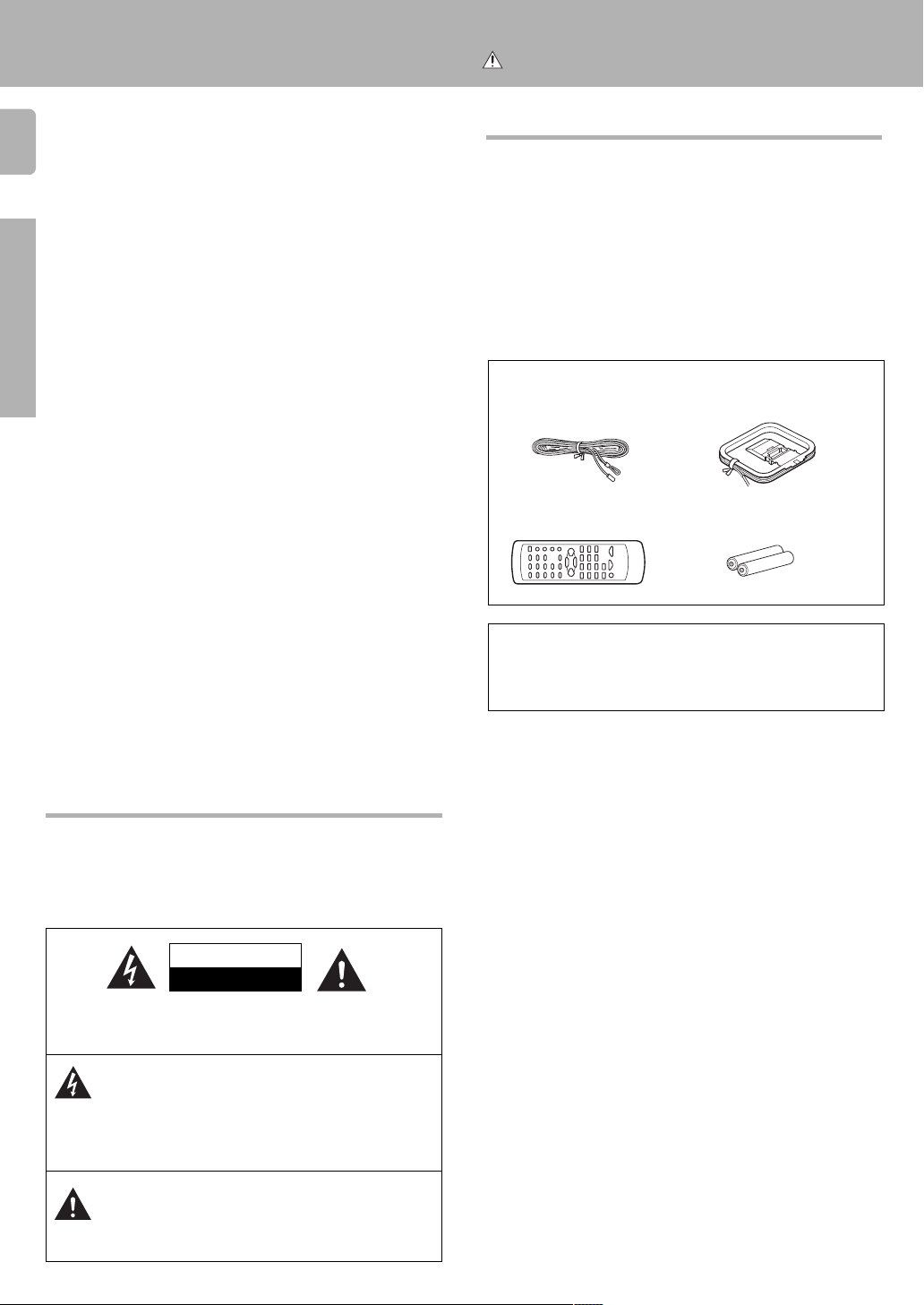
Accessories
FM indoor antenna (1)
Remote control unit (1)
Microcomputer malfunction
If operation is not possible or an erroneous display appears, even
though all connections have been made properly, reset the microcomputer referring to «In case of difficulty». ⁄
AM loop antenna (1)
Batteries (R6/AA) (2)
Safety precautions
WARNING :
TO PREVENT FIRE OR ELECTRIC SHOCK, DO NOT
EXPOSE THIS APPLIANCE TO RAIN OR MOISTURE.
CAUTION
RISK OF ELECTRIC SHOCK
DO NOT OPEN
CAUTION: TO REDUCE THE RISK OF ELECTRIC SHOCK, DO NOT
REMOVE COVER (OR BACK). NO USER-SERVICEABLE PARTS INSIDE, REFER SERVICING TO QUALIFIED SERVICE PERSONNEL.
THE LIGHTNING FLASH WITH ARROWHEAD SYMBOL,
WITHIN AN EQUILATERAL TRIANGLE, IS INTENDED TO
ALERT THE USER TO THE PRESENCE OF UNINSULATED
«DANGEROUS VOLTAGE» WITHIN THE PRODUCT’S ENCLOSURE THAT MAY BE OF SUFFICIENT MAGNITUDE TO
CONSTITUTE A RISK OF ELECTRIC SHOCK TO PERSONS.
THE EXCLAMATION POINT WITHIN AN EQUILATERAL TRIANGLE IS INTENDED TO ALERT THE USER TO THE PRESENCE OF IMPORTANT OPERATING AND MAINTENANCE
(SERVICING) INSTRUCTIONS IN THE LITERATURE ACCOMPANYING THE APPLIANCE.
Before applying the power
Maintenance of the unit
When the front panel or case becomes dirty, wipe with a soft, dry
cloth. Do not use thinner, benzine, alcohol, etc. for these agents may
cause discoloration.
In regard to contact cleaner
Do not use contact cleaners because it could cause a malfunction.
Be specially careful not to use contact cleaners containing oil, for
they may deform the plastic component.
Contents
Caution : Read the pages marked carefully to ensure
Preparations
Operations
safe operation.
Before applying the power ………………………… 2
Safety precautions ……………………………………… 2
Unpacking …………………………………………………. 2
How to use this manual ………………………………. 4
Special features …………………………………………. 4
Names and functions of parts ……………………. 5
Setting up the system …………………………………. 7
Connecting audio components …………………….. 8
Connecting video components …………………….. 9
Connecting a DVD player (6-channel input) ….. 10
Digital connections …………………………………… 11
Connecting the antennas …………………………… 12
Connecting the system control ………………….. 13
Connecting the speakers …………………………… 14
Preparing the remote control …………………….. 15
Preparing for surround sound ………………….. 16
Speaker settings ………………………………………. 16
Normal playback………………………………………. 17
Preparing for playback ………………………………. 17
Listening to a source component ……………….. 18
Adjusting the sound ………………………………….. 18
Recording …………………………………………………. 19
Recording audio (analog sources) ………………. 19
Recording video ……………………………………….. 20
Recording audio (digital sources) ……………….. 20
Listening to radio broadcasts ………………….. 21
Tuning (non-RDS) radio stations …………………. 21
Using RDS (Radio Data System) ………………… 21
Using the DISPLAY key …………………………….. 22
Presetting RDS stations
(RDS AUTO MEMORY) …………………………….. 22
Presetting radio stations manually ……………… 23
Receiving preset stations ………………………….. 23
Receiving preset stations in order (P.CALL) … 23
Tuning by program type (PTY search) …………. 24
Ambience effects ……………………………………… 25
Surround modes ………………………………………. 25
Surround play …………………………………………… 26
DVD 6-channel playback ……………………………. 27
Convenient functions ………………………………… 27
Basic remote control operation for other
components ………………………………………………. 29
DVD player operations ………………………………. 29
CASSETTE deck, CD player & MD recorder
operations ……………………………………………….. 30
3
Preparations
Operations
Additional Informatiion
Additional
Information
In case of difficulty …………………………………… 31
Specifications ………………………………………….. 32
4
This manual is divided into three sections, Preparations, Operations,
and Additional Information.
Preparations
Shows you how to connect your audio and video components to the
receiver and prepare the surround processor.
We will guide you to make setting up your system as easy as possible.
However, since this receiver works with all of your audio and video
Preparations
components, connecting the system can be fairly complex.
Operations
Shows you how to operate the various functions available from the
receiver.
Additional Information
Shows you additional information such as «In case of difficulty» (troubleshooting) and «Specifications».
Before applying the power
Special featuresHow to use this manual
True home theater sound
This receiver incorporates a wide variety of surround modes to bring
you maximum enjoyment from your video software. Select a surround
mode according to your equipment or the software you are going to
play and enjoy! ∞
Dolby Pro Logic & Dolby 3 Stereo
This surround system reproduces theater-like surround sound from
video software marked
The PRO LOGIC mode uses the built-in adaptive matrix circuit to
steer the Left, Center, Right and Surround channel audio signals.
The 3 STEREO mode will redirect the Surround signal to the front left
and right speakers when only the front and center speakers are used.
Dolby Digital
The DOLBY DIGITAL mode lets you enjoy full digital surround from
software processed in the Dolby Digital format. Dolby Digital provides
up to 5.1 channels of independent digital audio for better sound
quality and more powerful presence than conventional Dolby
Surround.
DVD 6-channel input
If you own a DVD player equipped with 6-channel output, this
receiver allows you to obtain the full surround sound impact of DVD
source material featuring multi-channel encoding. Since the source
signals are digital and each channel is input independently, the
resulting ambience is far superior to what can be achieved with
conventional surround sound systems.
RDS (Radio Data System) tuner
The receiver is equipped with an RDS tuner that provides several
convenient tuning functions: RDS Auto Memory, to automatically
preset up to 40 RDS stations broadcasting different programs; station
name display, to show you the name of the current broadcast station;
and PTY search to let you tune stations by program type.
PTY (Program TYpe) search
Tune the stations by specifying the type of program you want to hear.
.
Memory back up function
Please note that the following items will be deleted from the unit’s
memory if the power cord is disconnected from the AC outlet for
approximately 3 days.
• Power mode.
• Input selector settings.
• Device preset.
• Picture output.
• Speaker ON/OFF
• Volume level.
•BASS, TREBLE, INPUT
level.
• Subwoofer ON/OFF.
• Dimmer level.
• Monitor ON/OFF.
• MD/TAPE settings.
• 6ch/2ch input setting.
• Listen mode setting.
• Speaker settings.
• Input mode setting.
• Midnight mode setting.
• Broadcast band.
• Frequency setting.
• Preset stations.
• Tuning mode.
Names and functions of parts
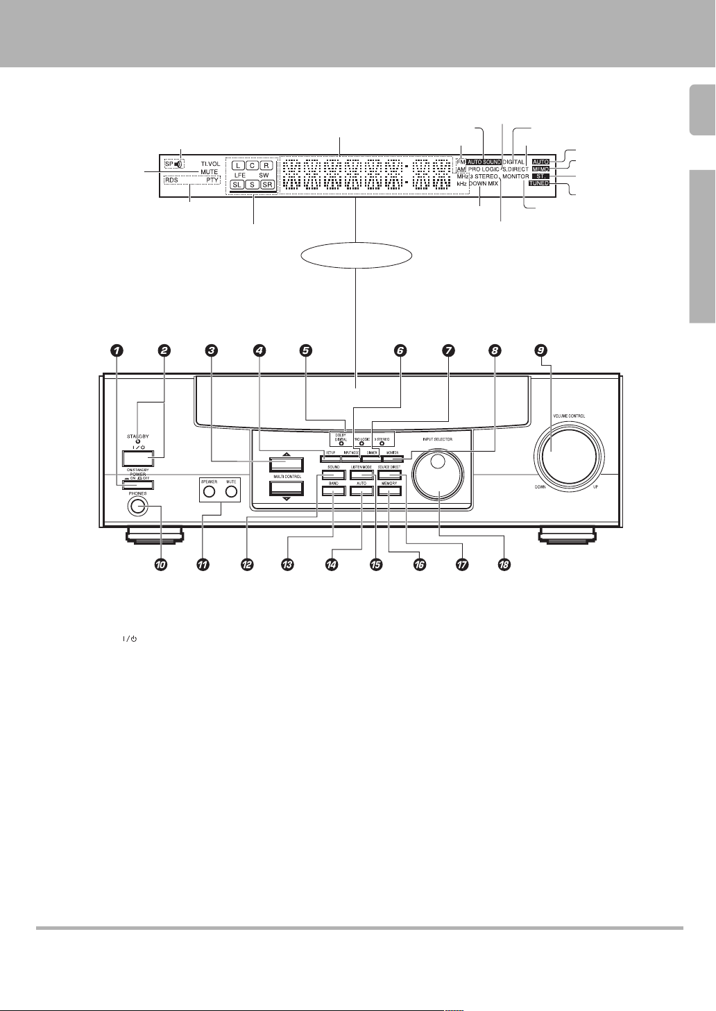
Speakers’ indicator
MUTE indicator
RDS indicators
Speaker selection indicators
Input channel indicators
Output channel indicators
Frequency display,
Input display,
Preset channel display,
Surround mode display
Display
AUTO SOUND indicator
Band indicators
DOWN MIX indicator
PRO LOGIC
indicator
3 STEREO indicator
STEREO indicator
DIGITAL indicator
S.DIRECT indicator
5
AUTO indicator
MEMO. indicator
ST. indicator
TUNED indicator
MONITOR indicator
Preparations
1 POWER key ^
Use to switch the main power ON/OFF.
2 ON/STANDBY (
Use to switch the power ON/STANDBY when
the POWER is turned ON.
STANDBY indicator
3 MULTI CONTROL key ^
Use to control a variety of settings.
4 SET UP key ^
Use to select speakers’ settings etc.
5 Surround indicators
DOLBY DIGITAL indicator §
Lights when the receiver is in the Dolby
Digital mode.
PRO LOGIC indicator §
Lights when the receiver is in the PRO LOGIC
mode.
3 STEREO indicator §
Lights when the receiver is in the 3 STEREO
mode.
6 INPUT MODE key 7
Use to switch between the digital and analog
inputs.
) key ^
7 DIMMER key )•
Use to adjust the brightness of the display.
Use to select the REC MODE.
8 MONITOR key (
Use to monitor the source that is connected
to the VIDEO2/MONITOR jack.
9 VOLUME CONTROL knob *
0 PHONES jack (
Use for headphone listening.
! SPEAKER key &
Use to turn the speaker ON/OFF.
MUTE key (
Use to temporarily mute the sound.
@ SOUND key ¶
Use to adjust the sound quality and ambience
effects.
# BAND key ¡
Use to select the broadcast band.
$ AUTO key ¡
Use to select the auto tuning mode.
% LISTEN MODE key §
Use to select the listening mode.
^ MEMORY key ™
Use to store radio stations in the preset
memory.
& SOURCE DIRECT key (
Use to pass the source material direct to the
amplifier.
* INPUT SELECTOR knob *
Use to select the input sources.
Standby mode
While standby indicator is lit, this receiver is in standby mode and consumes a small amount of current for back-up. This system can be switched ON by using the remote
control.
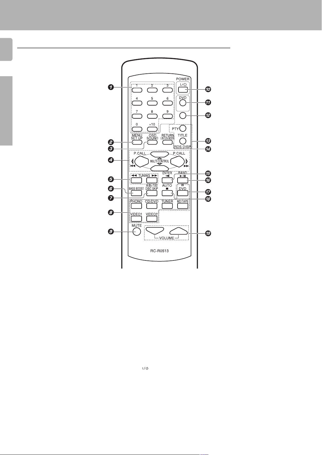
Remote control unit
6
Preparations
Names and functions of parts
POWER
RECEIVER
1 Numeric keys £
If CD or MD is selected as the input source,
these keys function as numeric keys. If
tuner is selected as the input source, these
keys are used to call up station presets.
2 SET UP key ^
Use to select speakers’ settings etc.
MENU key
Use to operate other components.
3 SOUND key ¶
Use to adjust the sound quality and ambience effects.
OSD key
Use to operate other components.
4 MULTI CONTROL keys ^
Used to control a variety of settings.
P.CALL 4/¢ keys £
If tuner is selected as the input source,
these keys function as P.CALL keys.
4/¢ keys
If CD or MD is selected as the input source,
these keys function as skip keys.
5 TUNING 1/¡ keys
If tuner is selected as the input source,
these keys function as tuning keys.
If CD, MD or TAPE is selected as the input
source, these keys function as search keys.
6 BASS BOOST key *
Use to select the maximum adjustment
setting for the low frequency range.
7 DISC SKIP key
If CD is selected as the input source, this key
functions as the multi-CD player disc skip key.
A/B key
If TAPE is selected as the input source, this
(A and B) of a double cassette deck.
+100 key
Use to select the disc number with the
multi-CD player.
8 INPUT SELECTOR keys (DVD, PHONO,
CD/DVD, TUNER, MD/TAPE, VIDEO1,
VIDEO2) *
Selects the inputs and sets the remote
control to operate the component registered at the respective input.
9 MUTE key (
Use to temporarily mute the sound.
0 POWER (
Use to turn the receiver on and off.
! DVD POWER key ª
Used to operate DVD player.
@ RECEIVER key
Use to return to the operation of the receiver.
# TITLE key
Use to operate other components.
RDS operation keys ™¢
Use to receive RDS broadcasts.
) key ^
$ LISTEN MODE key §
Use to select the listening mode.
RETURN key
Use to operate other components.
% ENTER key
Use to operate other components.
2 key
If tape is selected as the input source, this
key functions as the play key for side B of the
cassette (the side facing away from the front
of the deck).
^ BAND key ¡
Use to select the broadcast band.
6 key
If CD is selected as the input source, this key
functions as the play/pause key.
If MD or TAPE is selected as the input source,
this key functions as the play key.
& 8 key
Use to operate other components.
* AUTO key ¡
Use to select the auto tuning mode.
7 key
If CD, MD or TAPE is selected as the input
source, this key functions as the stop key.
( VOLUME keys *
Use to adjust the receiver volume.
Setting up the system
Make connections as shown in the following pages.
When connecting the related system components, be sure
to also refer to the instruction manuals supplied with the
components you are connecting.
Do not connect the power cord to a wall outlet until all
connections are completed.
VIDEO 2/MONITOR jacks
The receiver’s VIDEO 2/MONITOR jacks can be used in two different
ways. Make the appropriate setting for the component connected to
the jack when the receiver is turned on.
Use as a VIDEO 2 jack
You can connect a video deck or the like to these jacks and perform
video playback and recording. The initial factory setting is «VIDEO 2».
Use as a MONITOR jack
You can connect a cassette deck or the like to these jacks and make
use of the deck’s monitoring function during recording. Alternately,
you can connect a graphic equalizer to these jacks to apply compensation to the music signal.
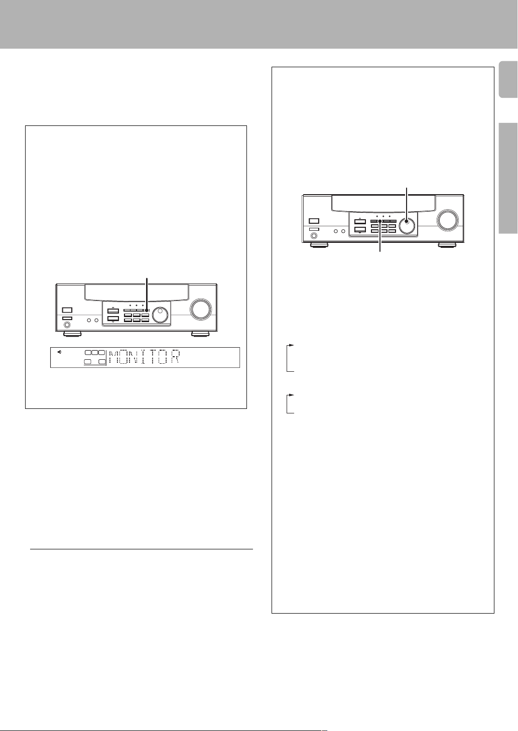
To use the VIDEO 2/MONITOR jacks as MONITOR jacks, hold down
the MONITOR key of the main unit for more than two seconds so that
the indication shown below appears.
MONITOR
SP
• To switch the setting back to «VIDEO 2», once again hold down the
MONITOR key for two seconds or more.
RL
SW
STEREO
MONITOR
Input mode settings
CD/DVD, DVD/6ch and VIDEO2 inputs each include jacks for digital
audio input and analog audio input.
You must select beforehand which type of input is to be used for each
connected component.
The initial factory settings is to use the digital audio signal for
playback (CD/DVD, DVD/6ch and VIDEO2).
To use the analog audio input for playback instead (if, for example, you
have connected a VCR to the VIDEO2 input), you must set the input
mode for the corresponding input to the analog mode.
After completing connections and turning on the receiver, follow the
steps below.
INPUT SELECTOR
INPUT MODE
1 Use the INPUT SELECTOR knob to select CD/DVD or VIDEO2.
2 Press the INPUT MODE key.
Each press switches the setting as follows:
In DVD/6ch play mode
1 D-AUTO (digital input, auto sound)
2 D-MANUAL (digital input, manual sound)
3 6ch INPT (DVD/6ch input)
4 ANALOG (analog input, manual sound)
In other mode than DVD/6ch play mode
1 D-AUTO (digital input, auto sound)
2 D-MANUAL (digital input, manual sound)
3 ANALOG (analog input, manual sound)
7
Preparations
Notes
1. Be sure to insert all connection cords securely. If their connections are
imperfect, the sound may not be produced or noise may interfere.
2. Be sure to remove the power cord from the AC outlet before plugging
or unplugging any connection cords. Plugging/unplugging connection
cords without disconnecting the power cord can cause malfunctions
and may damage the unit.
3. Do not connect power cords from components which power consump-
tion is larger than what is indicated on the AC outlet at the rear of this
unit.
Analog connections
Audio connections are made using RCA pin cords. These cables transfer
stereo audio signal in an «analog» form. This means the audio signal
corresponds to the actual audio of two channels. These cables usually
have 2 plugs on each end, one red for the right channel and one white for
the left channel. These cables are usually packaged with the source unit,
or are available at your local electronics retailer.
Digital input:
Select this setting to play digital signals from a DVD, CD, or LD
player.
Analog input:
Select this setting to play analog signals from a cassette deck, VCR,
or record player.
Auto sound:
In the auto sound mode (AUTO SOUND indicator lights), the
receiver selects the listening mode automatically during playback to
match the type of input signal (Dolby Digital, PCM) and the speaker
setting. The initial factory setting is auto sound on.
To keep the receiver set to the currently selected listening mode,
use the INPUT MODE key to select «D-MANUAL» (manual sound).
However, even when this setting is selected, there may be cases in
which the listening mode is selected automatically to match a Dolby
Digital source signal depending on the combination of listening
mode and source signal.
If the INPUT MODE key is pressed quickly, sound may not be
produced.
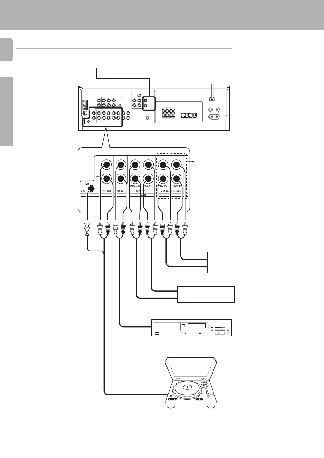
Connecting audio components
8
SYSTEM CONTROL
jacks #
Preparations
Setting up the system
To AC wall outlet
VIDEO2/MONITOR jacks
You can connect an equalizer in Monitor mode, or a
video component in Video
2 mode.
OUT
IN
OUT
Cassette deck or MD
recorder
IN
OUT
CD player
OUT
Record player
When you connect the video component to the VIDEO2/MONITOR jacks, connect the video cord (yellow RCA pin cords) of the connected
component to the VIDEO2 IN jack .
Video component, 3 head
cassette deck, or Graphic
equalizer (
Moving Coil (MC) cartridge
record player cannot be used
directly from the receiver unit.
It can only be used when
another equilizer amplifier is
connected.
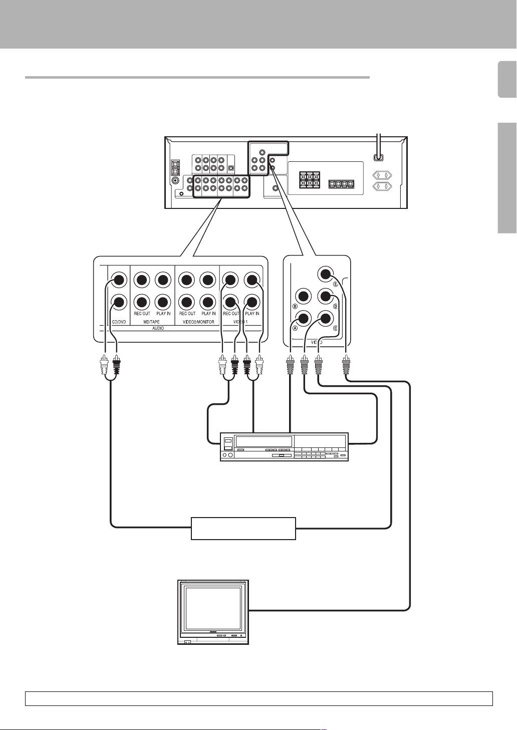
Connecting video components
Setting up the system
9
Preparations
OUT ININ
Video deck
Audio inputs
and outputs
OUT
A video component with digital audio outputs should be connected to the VIDEO2 jacks.
DVD player or LD player
Monitor TV
VIDEO IN
Video Inputs
(Yellow RCA pin cord)
Video inputs and outputs
(Yellow RCA pin cords)
OUT
OUT
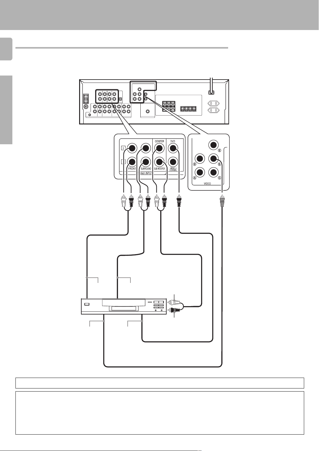
Connecting a DVD player (6-channel input)
10
If you have connected a DVD player to the receiver with digital connection, be sure to read the «Input mode
settings» section carefully. 7
Preparations
Setting up the system
FRONT
OUT L/R
DVD player
VIDEO OUT
(Yellow RCA
pin cord)
To switch the speakers off , press the MUTE key.
SURROUND
OUT L/R
COAXIAL
DIGITAL
OUT
(AUDIO)
CENTER OUT
SUBWOOFER OUT
CAUTION
Be sure to adhere followings or proper ventilation will be blocked causing damage or fire hazard.
• Do not place any objects impairing heat radiation onto the top of unit.
• Leave a space around the unit (from the largest outside dimension including projection) equal or greater than, shown below.
Top panel : 50 cm Side panel : 10 cm Back panel : 10 cm
Loading…
- Главная
-
Kenwood
-
Стереоресиверы
-
KRF-V4550D
На этой странице вы найдёте полный список документов на Стереоресиверы Kenwood KRF-V4550D.
Выберите необходимый PDF файл.
-
Стереоресиверы
Kenwood KRF-V4550D Инструкция по эксплуатацииТип файла
PDFРазмер
1.08 MbКол-во страниц
32Просмотров
8279Download / Read online
- 1
Другие Kenwood Стереоресиверы
-
Kenwood KRF-V4550D Инструкция по эксплуатации
PDF файлов
1Просмотров
9911 -
Kenwood KRF-V5300D Инструкция по эксплуатации
PDF файлов
1Просмотров
6569 -
Kenwood KRF-V7070D Инструкция по эксплуатации
PDF файлов
1Просмотров
5352 -
Kenwood KR-A5050 Инструкция по эксплуатации
PDF файлов
1Просмотров
4550 -
Kenwood KRF-V5200D Инструкция по эксплуатации
PDF файлов
1Просмотров
4475 -
Kenwood KIV-BT901 Инструкция по эксплуатации
PDF файлов
1Просмотров
4388
Другие устройства Kenwood
-
Бытовая техника
Kenwood GE-7030 Руководство по эксплуатацииPDF файлов
1Просмотров
37016 -
Хлебопечки
Kenwood BM200 series МануалPDF файлов
1Просмотров
36185 -
Навигационные устройства
Kenwood DNX891HD Руководство пользователяPDF файлов
4Просмотров
22496 -
Бытовая техника
Kenwood RXD-500 Руководство по эксплуатацииPDF файлов
1Просмотров
21341 -
GPS-навигаторы
Kenwood DNX 9280 BT Руководство пользователяPDF файлов
3Просмотров
20721 -
GPS-навигаторы
Kenwood DNN 9250 DAB Руководство пользователяPDF файлов
3Просмотров
19073
Ранее вы смотрели
Производители
AirMagnet
ATC Group
Home Automation
Hudson Industries
Indesit
Kentrox
Presto
Reliable Sprinkler
Renesas
White Mountain
Типы устройств
Валики
CPAP машины (сипап)
Цифровые телефоны
Болтовой экстензометр
Нефтедобыча
Ароматизаторы, освежители воздуха
Факсы
Средства управления и переключения вентиляторов
Экшн-камеры
Термометр для ванной
Устройства
ADTRAN QDFR Unit
ASUS PRO ADVANCED B551LG BP8781
Carrier SYSTXCCITC01-A
Kenmore 911.93588
Marshall Amplification BASS STATE B 150
Philips 170B6CG
Philips PET730
Roland BHA-2
Sanyo VSP-9000
Sunbeam Scale FS7600
freeuserguide.ru
About Us
Contacts
Disclamers
Privacy Policy
Эта страница полезна для вас? Поделитесь ссылкой:
Скачать файл PDF «Kenwood KRF-V4550D Инструкция по эксплуатации» (1.08 Mb)
Популярность:
8279 просмотры
Подсчет страниц:
32 страницы
Тип файла:
Размер файла:
1.08 Mb
Google Ads: