
Хорошее руководство по эксплуатации
Законодательство обязывает продавца передать покупателю, вместе с товаром, руководство по эксплуатации Kenwood TS-440S. Отсутствие инструкции либо неправильная информация, переданная потребителю, составляют основание для рекламации в связи с несоответствием устройства с договором. В законодательстве допускается предоставлении руководства в другой, чем бумажная форме, что, в последнее время, часто используется, предоставляя графическую или электронную форму инструкции Kenwood TS-440S или обучающее видео для пользователей. Условием остается четкая и понятная форма.
Что такое руководство?
Слово происходит от латинского «instructio», тоесть привести в порядок. Следовательно в инструкции Kenwood TS-440S можно найти описание этапов поведения. Цель инструкции заключается в облегчении запуска, использования оборудования либо выполнения определенной деятельности. Инструкция является набором информации о предмете/услуге, подсказкой.
К сожалению немного пользователей находит время для чтения инструкций Kenwood TS-440S, и хорошая инструкция позволяет не только узнать ряд дополнительных функций приобретенного устройства, но и позволяет избежать возникновения большинства поломок.
Из чего должно состоять идеальное руководство по эксплуатации?
Прежде всего в инструкции Kenwood TS-440S должна находится:
— информация относительно технических данных устройства Kenwood TS-440S
— название производителя и год производства оборудования Kenwood TS-440S
— правила обслуживания, настройки и ухода за оборудованием Kenwood TS-440S
— знаки безопасности и сертификаты, подтверждающие соответствие стандартам
Почему мы не читаем инструкций?
Как правило из-за нехватки времени и уверенности в отдельных функциональностях приобретенных устройств. К сожалению само подсоединение и запуск Kenwood TS-440S это слишком мало. Инструкция заключает ряд отдельных указаний, касающихся функциональности, принципов безопасности, способов ухода (даже то, какие средства стоит использовать), возможных поломок Kenwood TS-440S и способов решения проблем, возникающих во время использования. И наконец то, в инструкции можно найти адресные данные сайта Kenwood, в случае отсутствия эффективности предлагаемых решений. Сейчас очень большой популярностью пользуются инструкции в форме интересных анимаций или видео материалов, которое лучше, чем брошюра воспринимаются пользователем. Такой вид инструкции позволяет пользователю просмотреть весь фильм, не пропуская спецификацию и сложные технические описания Kenwood TS-440S, как это часто бывает в случае бумажной версии.
Почему стоит читать инструкции?
Прежде всего здесь мы найдем ответы касательно конструкции, возможностей устройства Kenwood TS-440S, использования отдельных аксессуаров и ряд информации, позволяющей вполне использовать все функции и упрощения.
После удачной покупки оборудования/устройства стоит посвятить несколько минут для ознакомления с каждой частью инструкции Kenwood TS-440S. Сейчас их старательно готовят или переводят, чтобы они были не только понятными для пользователя, но и чтобы выполняли свою основную информационно-поддерживающую функцию.

HF TRANSCEIVER
TS-440S
INSTRUCTION MANUAL
KENWOOD CORPORATION
©PRINTED IN JAPAN B50-8048-30(K, M, T, W)
91/12 11 10 987654321

Thank you for purchasing the new TS-440S tran
sceiver. Please read this instruction manual carefully
before placing your transceiver in service. This unit has
been carefully engineered and manufactured to rigid
quality standards, and should give you satisfactory and
dependable operation for many years.
The following explicit definitions apply in this manual:
Note: If disregarded, inconvenience only, no risk
of equipment damage or personal injury.
Caution: Equipment damage may occur, but not per
sonal injury.
CONTENTS
1. FEATURES…………………………………………………….. 3
2. INSTALLATION……………………………………………….. 4
2-1. PRECAUTIONS……………………………………………. 4
2-2. FIXED STATION…………………………………………… 4
2-2-1. Interconnection………………………………………… 4
2-2-2. Grounding……………………………………………….. 4
2-2-3. Antenna………………………………………………….. 5
2-2-4. Key connection………………………………………… 5
2- 3. MOBILE
2-3-1. Mounting bracket installation
2- 3-2. Power supply connection……………………….. 5
3. OPERATION…………………………………………………… 6
3- 1. OPERATING CONTROLS………………………….. 6
3- 1-1. Front panel
3-1-2. Rear panel…………………………………………….. 10
3-1-3. Top cover
3-2. RECEIVE…………………………………………………… 12
3-2-1. Initial setting
3-2-2. CW zero-beat operation
3-2-3. Direct keyboard frequency entry
3-2-4. AM reception
3-3. TRANSMIT
3-3-1. SSB (LSB, USB) mode
3-3-2. CW mode
3-3-3. FM mode
3-3-4. AM mode………………………………………………. 15
3-4. AUTOMATIC ANTENNA TUNER
3-5. DUAL DIGITAL VFO’s
3-5-1. Why two VFO’s………………………………………. 15
3-5-2. Split frequency
3-6. MEMORY ………………………………………………….. 16
3-6-1. Memory entry
3-6-2. Transferring memory information to the
3-6-3. Transferring data between memory
3-6-4. Entering/Transferring data in the split
3-6-5. Clearing a memory channel
3-6-6. Memory recall
3-7. SCAN
3-7-1. Memory scan
3-7-2. Program scan
3-7-3. Scan speed
3-7-4. Memory channel lockout
3-8. AFSK
3-8-1. Reception………………………………………………. 19
3-8-2. Transmit
3-8-3. AMTOR operation
3-9. OPERATION WITH A LINEAR AMPLIFIER.. 19
……………………………………………………
………………………
…………………………………………..
……………………………………………….
…………………………………………..
………………………………………….
…………………………………………………
(a) Semi-automatic break-in
(b) Full-automatic break-in…………………….. 14
• Subaudible tone…………………………………. 15
(a) A = B switch
(b) A/B switch……………………………………….. 1 5
(c) SPLIT switch
(d) T-F SET switch……………………………….. 15
VFO
channels
frequency channels
………………………………………………
………………………………………………
……………………………………….
…………………………………………..
…………………………………………………….
………………………………………………
…………………………………………………………
……………………………………………
…………………………………………………………
………………………………………………..
…………………………..
……………….
……………………………
……………………
………………….
………………………………….
…………………………………….
…………………………………..
……………………………….
………………….
…………………………………….
……………………………………..
……………………………………..
………………………….
…………………………………..
5
5
6
11
12
12
13
13
13
13
14
14
14
15
15
15
1 5
15
16
16
17
17
17
17
17
17
18
18
18
19
19
19
This Instruction Manual covers the TS-440S,
with and without AT (Automatic Antenna
Tuner) unit. When there are differences in
operation, separate instructions will be given for
each model. Illustrations show the TS-440S
with AT unit.
4. CIRCUIT DESCRIPTION
4-1. GENERAL DESCRIPTION
4-2. TRANSMITTER SECTION
4-3. RECEIVER SECTION
4- 4. CIRCUIT BOARD DESCRIPTION
4-4-1. RF unit (X44-1 680-00)
4-4-2. IF unit (X60-1300-00)
4-4-3. Control unit (X53-1450-00)………………………. 20
4-4-4. PLL unit (X50-2050-00)…………………………… 20
4-4-5. Final unit (X45-1470-00)
4-4-6. Filter unit (X51-1 340-00)
4- 4-7. AT (Automatic Antenna Tuner) unit
(X 57-1150-00)…………………………………….. 20
5. MAINTENANCE AND ADJUSTMENT
5- 1. GENERAL INFORMATION
5-2. SERVICE
5-3. CLEANING…………………………………………………. 21
5-4. IN CASE OF DIFFICULTY……………………………. 21
5-5. MICROPROCESSOR BACK-UP
LITHIUM BATTERY
5-6. MICROPROCESSOR RESET
5-7. ORDERING SPARE PARTS
5- 8. ADJUSTMENTS……………………………………… 23
5- 8-1. Cover removal…………………………………… 23
5-8-2. Internal views
5-8-3. Digital display calibration…………………….. 24
5-8-4. Optional 10 Hz display resolution
5-8-5. CW zero beat frequency selection
5-8-6. Side tone level…………………………………… 25
5-8-7. Beep tone selection……………………………. 25
5-8-8. Beep tone level
5-8-9. Tuning dial torque
5-8-10. Linear amplifier control
6. OPTIONAL ACCESSORIES……………………………. 27
6- 1. CRYSTAL FILTER INSTALLATION
6-2. VOICE SYNTHESIZER UNIT VS-1
INSTALLATION
6-3. INTERFACE 1C KIT IC-10
INSTALLATION
6-4. OTHER ACCESSORIES
7. BLOCK DIAGRAM…………………………………………. 33
8. SCHEMATIC DIAGRAM
9. SPECIFICATIONS AND ACCESSORIES…………. 41
9-1. SPECIFICATIONS
9- 2. ACCESSORIES………………………………………. 42
10. REFERENCE
10- 1. ANTENNA INSTALLATION
10-1-1. Fixed station
10-1-2. Mobile
10-2. MOBILE OPERATION……………………………….. 44
10-2-1. Installation…………………………………………….44
10-2-2. Noise reduction……………………………………..45
10-2-3. Battery capacity
10-3. RADIO FREOUENCY ALLOCATION
……………………………………………………
……………………………………………….
………………………………………………….
………………………………..
……………………………
……………………………
………………………………….
………………
……………………………
………………………………
………………………….
…………………………
……………….
………………………
…………………………………..
………………………
…………………………
…………………………………….
……………..
…………….
………………………………….
………………………………
………………………..
……………
……………………………………….
……………………………………….
………………………………
………………………………….
………………………………………
…………………….
…………………………………………
…………………………………….
……………
20
20
20
20
20
20
20
20
20
21
21
21
22
22
22
23
24
24
25
26
26
27
28
29
30
34
41
43
43
43
43
45
46

1. FEATURES
1. Wide dynamic range
New advances in circuit design have made a 102 dB
dynamic range (500 Hz IF bandwidth) possible.
2. General coverage reception from 100 kHz
to 30 MHz
In addition to transmission and reception on all amateur
bands from 1.8 to 28 MHz, the TS-440S provides a
continuous tuning general coverage receiver with a
range of 100 kHz to 30 MHz.
3. Automatic antenna tuner
The optional, built-in automatic antenna tuner will oper
ate from 3.5 to 28 MHz.
4. All-mode operation
USB, LSB, CW, AM, FM, and AFSK modes are
provided.
5. 100% continuous duty transmit
Transmission at a 100% duty cycle is possible for rela
tively long durations (one hour or less) in any mode,
including FM and AFSK.
6. CW full break-in
Full break-in operation is possible in the CW mode.
Rapid transmit/receive switching also makes the radio
suitable for data communications in the SSB mode,
such as AMTOR.
7. Build-in XIT
XIT (Transmitter incremental tuning) allows fine tun
ing of the transmitter frequency.
8. Switchable IF bandwidth
The IF bandswitch allows you to tailor the receiver
bandwidth to the operating conditions. Several selec
tions are provided; AUTO, W (Wide), Ml (Medium 1),
M2 (Medium 2) and N (Narrow). When the AUTO po
sition has been selected the radio will select the opti
mum bandwidth for the selected mode of operation.
9. Switchable AGC time constant
A switch is provided to select either FAST or SLOW
AGC action.
10. All mode squelch
11. Built-in RF power/SWR meter
12. Versatile frequency control
• Accurate frequency selection is possible due to the
use of a single reference oscillator circuit.
• Continuous tuning of all frequencies thru the use of
digital VFO technology. The basic 10 Hz step tun
ing rate is modified, according to the selected mode,
for optimum tuning speed and accuracy. An auto
matic fast scan function is also provided.
• Dual, digital VFO’s (A/B) enable crossband, cross
mode operation.
• 100-channel memory (including 10 odd-split chan
nels) stores the frequency, band, and mode.
• Memory scan and two programmable scan ranges.
• Direct entry of the desired frequency using the front
panel numeric keypad is also possible.
• A memory scroll function allows review of the
memory channel contents.
• Selection of the desired memory channel Ts possi
ble using either the TUNING dial or microphone
UP/DOWN pushbuttons.
• The T-F SET function is useful for split frequency
operation.
• An optional tone unit TU-8 may be used in conjunc
tion with the odd-split memory channels to allow 10
meter repeater operations with CTCSS access.
• Optional computer interface.
• Built-in long-life memory back-up battery.
• 2-color fluorescent display tube indicates frequen
cy and other operational data.
13. Front panel control of the TUNING dial
torque is provided.
2. INSTALLATION
2-1. PRECAUTION
1. Avoid direct sunlight, and select a dry, well venti
lated location.
2. Since the heat sink is on the rear panel, avoid plac
ing the equipment with the bottom and rear sides
close to a wall or desk.
3. When installing the equipment in an automobile, en
sure adequate ventilation. Install the equipment in
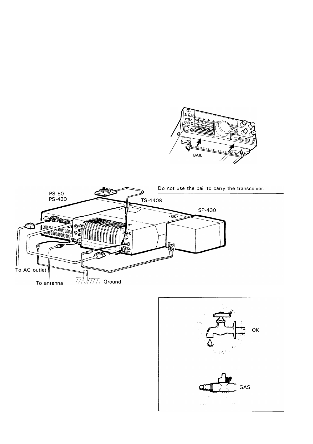
2-2. FIXED STATION
2-2-1. Interconnection
The TS-440S requires more than 18A at 13.8 VDC
when transmitting at full power. Use the PS-50 or
PS-430 power supply for fixed stations.
Note:——————————————————————————
The PS-50 base station supply is needed for continu
ous transmission operation.
Key
a location where the rear does not make direct con
tact with the seat, and is not directly exposed to
vibration.
Avoid installing the equipment in front of the car
heater air outlet.
The standard operating voltage of the equipment
is 13.8 V. Do not operate below 12 V or over 16 V.
The transceiver can be elevated for operating con
venience.
Caution: ————————————————————————
2-2-2. Grounding
Caution: ——————
Never use a gas pipe or electrical conduit pipe.
Notes:
—————————————————————————
1. A ground connection that is a 1/4 wavelength or
its multiple may provide a good DC ground, but it
will not provide a good RF ground.
2. A city water pipe cannot be used as a good earth
in some cases.
Making a good earth connection is important for
preventing dangers such as electric shock and for emit
ting a high quality signal with minimum spurious radi
ation. Bury a commercially available ground rod or
copper plate under the ground and connect it to the
GND terminal of the TS-440S. A thick wire, cut as
short as possible, should be used for the connection.
To make a good earth connection, connect the GND
terminal to a grounded metal water pipe.
2-2-3. Antenna
Caution:
————-
Protect your equipment —Use a LIGHTNING AR
RESTOR.
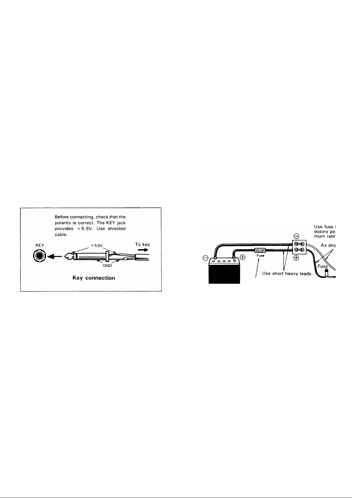
2-3-2. Power supply connection
Cautions:
———————————————————————
1. Turn POWER switch OFF before connecting/disconnecting the power cable.
2. Observe battery polarity.
Any of the common antenna systems designed for use
on the high frequency amateur bands may be used with
the TS-440S provided the input impedance of the
transmission line is not outside the capability of the Au
tomatic Antenna Tuner. The transmission line should
be coaxial cable. An antenna system which shows a
SWR (Standing Wave Ratio) of less than 1.5:1 when
using 50 ohm coaxial transmission line, or a system
that results in a transmission line input impedance that
is essentially resistive, and between 20 and 1 50 ohms
will take power from the transceiver through the AT
unit.
2-2-4. Key connection
Your key should be connected as illustrated in the
figure below. When using an electronic keyer, make
sure that polarity is set for positive. Always use shield
ed line from the key to transceiver.
DC power cable
Red and white -fBlack and gray —
3. When charging your vehicle battery, or when jumpstarting a dead battery, ALWAYS disconnect the
power cable from the back of the transceiver, or
damage may result to the transceiver.
Connect the TS-440S power cable to the battery ter
minals, with consideration to current requirements and
noise prevention. The maximum current drawn by the
TS-440S reaches between 18 and 20A when trans
mitting. Therefore, the cable should be made as short
as possible, using the specified fuse. Also, confirm that
the power system of the car (including the battery and
generator or alternator) will handle the increased load
of the TS-440S.
2-3. MOBILE
Being compact in design, this transceiver is ideal for
mobile operation. Satisfactory mobile operation is
achieved through proper power and antenna connec
tion, and thoughtful transceiver installation and ad
justment.
2-3-1. Mounting bracket installation
Secure the TS-440S under the dashboard using an op
tional MB-430 mounting bracket. As an alternative, use
strapping, making sure that the TS-440S will not slip
out of place while operating the vehicle.
Notes:
—————————————————————————
1. Do not install the TS-440S near the heater outlet.
2. Allow sufficient space behind the TS-440S to en
sure proper ventilation.
12V Battery
Fuse should be as close to the battery
terminal as possible.
Diock battery accsition. 20A mini-
9-
rt as possible. TS-440S
3. OPERATION
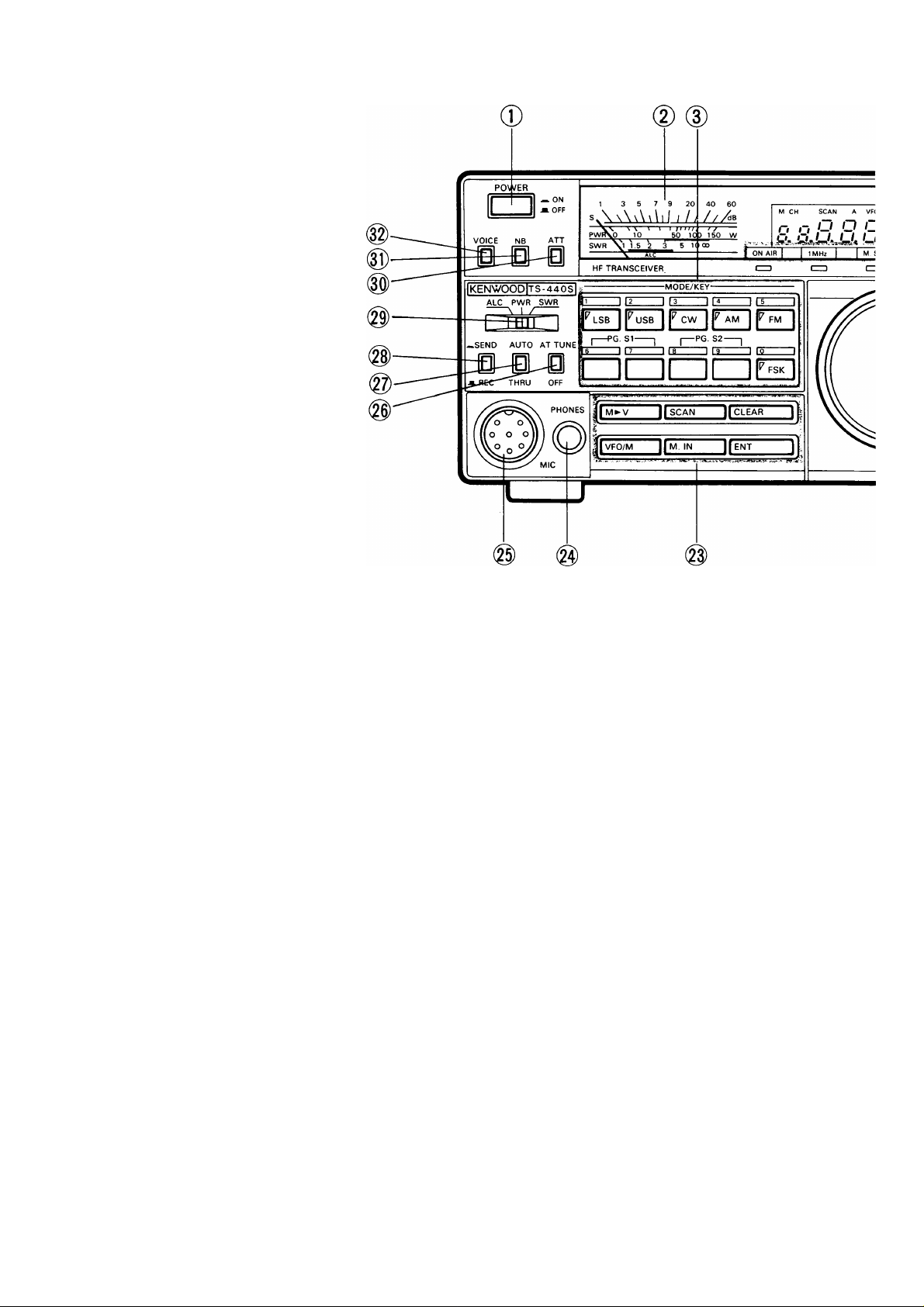
3-1. OPERATING CONTROLS
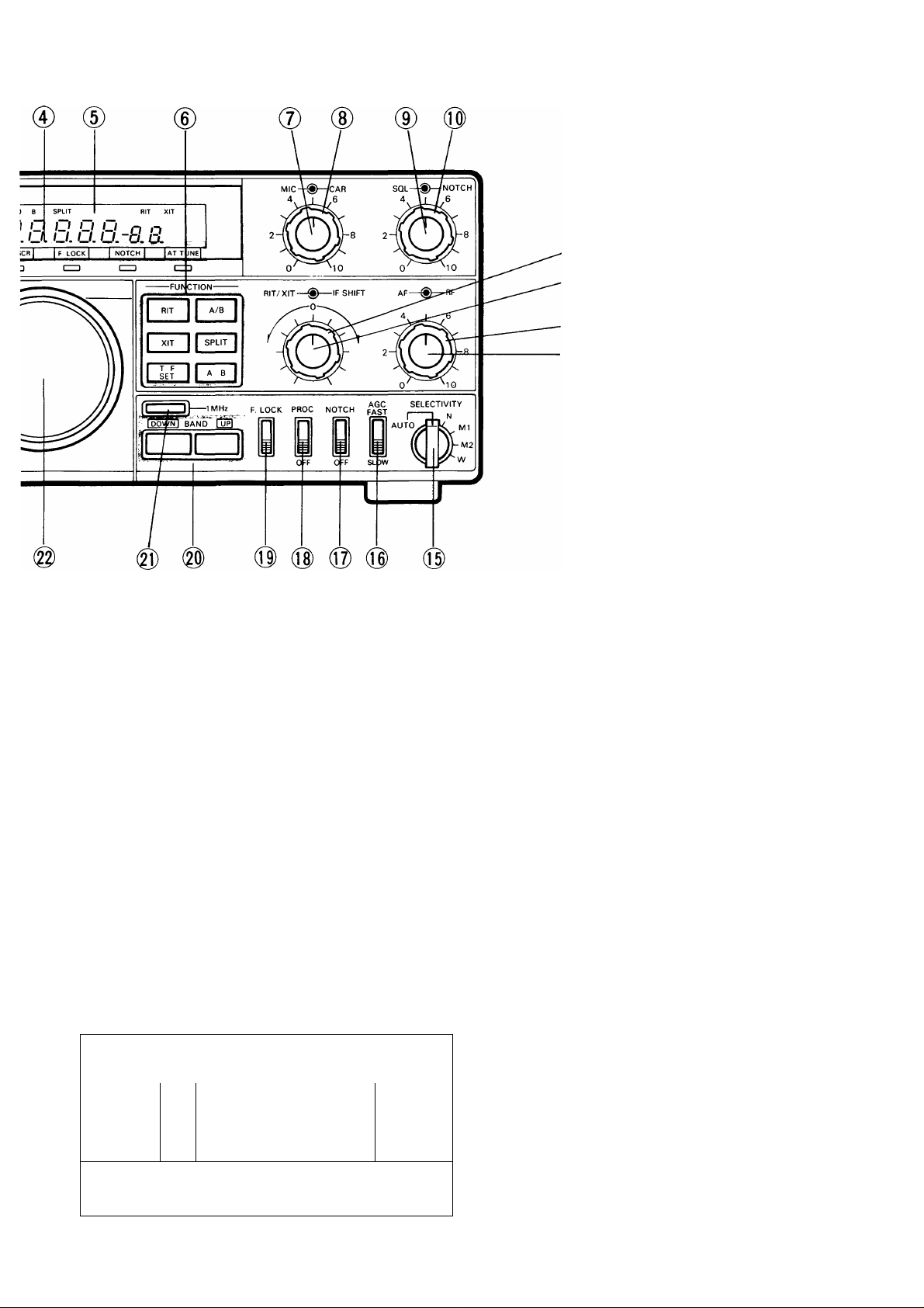
3-1-1. Front panel
0 POWER switch
Press to turn the power ON or OFF.
(2) Meter
During receive the meter is used as an S-meter. Dur
ing transmit the function of the meter is controlled by
the Meter switch , and provides either ALC level,
PWR (power) or SWR readings.
MODE/KEY (Numeric Keypad)
These keys are used to select the desired mode of oper
ation (USB, LSB, CW, AM, FM, AFSK). When program
ming a memory channel or directly entering a frequency
these keys are used as a numeric keypad to enter the
channel number or frequency.
Indicators
AT TUNE: Lights when the AT TUNE switch is ON.
Turns itself OFF when the antenna tuner
has completed tuning.
NOTCH: Lights when the NOTCH switch is ON.
F.LOCK: Lights when the F.LOCK switch is ON.
1 MHz: Lights when the 1 MHz step switch is ON.
M.SCR: Lights when the M.IN switch is pressed.
When the memory scroll function is active
you can review the contents of the
memory channels without a break in the
reception of the station you are listening
to.
ON AIR: Lights during transmit.
(^ Frequency display
The operating frequency is displayed down to the
nearest 100 Hz. Also displays the memory channel
number, RIT/XIT frequency, and includes indicators for
memory, VFO A/B, scan, split and RIT/XIT operations.
(D FUNCTION switches
The switches included in this group are the RIT/XIT,
T-F SET switch, and the VFO select switches. (See
page 15.)
(j) MIC gain control
Microphone gain can be adjusted during USB, LSB,
AFSK and AM operations. Gain is increased thru clock
wise rotation of this control.
CAR (Carrier level) control
This control sets the carrier level during CW, FM and
AM operations. When transmitting in the CW mode,
adjust so that the ALC meter pointer is within the ALC
zone.
SQL (Squelch) control
This function operates in all modes, FM, USB, LSB,
CW, AFSK, and AM.
This control is used to eliminate atmospheric noise, and
receiver static noise during no signal periods. Slowly
rotate the control clockwise to the point where the am
bient noise just disapears, and speaker shuts off. This
point is known as the squelch threshold point. Now you
will only hear output from the speaker when an incomming signal is present. For weak signal reception this
control should be fully counterclockwise.
•(0)
Note:——————————————————————————
The squelch threshold position will vary from mode to
mode, so you may have to readjust when you change
modes.
(0) NOTCH control
The NOTCH function is used to reduce or eliminate het
erodyne, or CW type signals. The NOTCH filter will not
be effective against SSB, AM or FM type signals. To
use the control, place the NOTCH switch ON and slow
ly rotate the NOTCH control to reduce the interference.
Normally the notch point will occur between the 11:00
and 1:00 o’clock position.
Notes:
—————————————————————————
1. The NOTCH frequency can be varied within a range
of approximately 400 to 2600 Hz.
2. When an interfering signal such as a CW station
appears, slowly rotate the NOTCH control. If you
rotate the knob too quickly you may pass right over
the notch point. Slow rotation will yield the best
results.
Interfering
signal
Receive
signal
Interfering
signal attenuated
by NOTCH control
Receive
signal
/
/
\
Audio output
(NOTCH OFF)
NOTCH control
Audio output
(NOTCH ON)
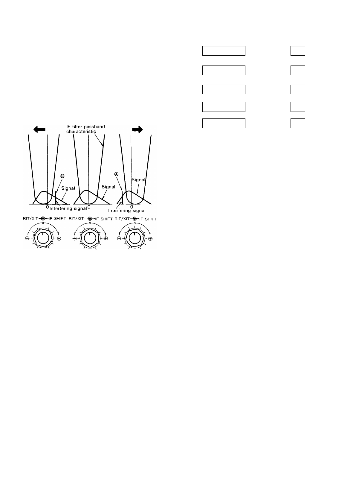
(Q) IF SHIFT control
Note: —————————————————————————
The IF SHIFT control does not function in the AM or
FM modes.
The IF SHIFT control allows you to shift the IF pass-
band of the receiver without changing the actual center
frequency of the receiver. This control is useful when
there is interference near your center frequency. As the
accompanying illustration shows rotating this control
may place the interfering signal outside the receiver
passband, allowing for easier copy. The operation of
this control in the USB, LSB, AFSK, and CW modes
is detailed below.
• USB mode
Interference from lower frequencies can be reduced
or eliminated by rotating the IF SHIFT control in the
0 direction. This will cause the resulting audio fre
quencies to have a slightly treble response, i.e.low
cut filter (low frequencies attenuated). Interference
from higher frequencies can be reduced or eliminat
ed by rotating the IF SHIFT control in the 0 direc
tion. This will cause the resulting audio frequencies
to sound a little bassy, i.e.high cut filter (high fre
quencies attenuated).
• LSB/AFSK mode
Interference from lower frequencies can be reduced
or eliminated by rotating the IF SHIFT control in the
0 direction. This will cause the resulting audio fre
quencies to sound a little bassy, just the opposite
of the effect in the USB mode. Interference from
higher frequencies can be reduced or eliminated by
rotating the IF SHIFT control in the Q direction.
This will cause the resulting audio frequencies to ap
pear a little on the high side, again just the opposite
of the USB mode.
CW mode
The operation of the IF SHIFT control is similar to
that for USB with the exception that you can con
trol the tone of the CW note by using the RIT
control.
VFO
1 u n I~l n n
1 /. u u u. u
1 D O O n n
t -I. 1 1 1. 1
s
1 D O O n n
1 -1. 1 1 ~l. ~l
1 D O O n n
1 -1. 1 1 1. i
RIT
0
9
0.D
-0.0
0
1
s
1
0
-00
-0 /
9
0
Turned in ^direction
Turn in Qdirection
to eliminate inter
ference from signal
Turned in ^direction
IF SHIFT operation
Turn in ^direction
to eliminate inter
ference from signal
K-
1 D O O O n
1 J. 1 1 l.u
s
XIT control
When the RIT/XIT control is rotated with the XIT
switch depressed the transmit frequency can be
varied
+/-^.2 kHz without affecting the receiver
frequency.
Pressing the switch again releases the XIT function.
9
-0 /
1
s
RF gain control
This control adjusts the gain of the receiver highfrequency amplifier section.
For normal receiver performance, and maximum gain,
this control should be in the full clockwise position. If
you are having trouble copying the desired signal make
a note of the stations peak S-meter reading. Then, ad
just the RF control counterclockwise, so that the meter
needle is stationary at this level. Now, all signals that
were less than the desired signal will be attenuated,
such as static noise, etc., making the completion of
the QSO easier.
® RIT/XIT control
• RIT control
When the transmit frequency of the distant station
drifts a little bit during the QSO, but you do not wish
to alter your transmit frequency to compensate, you
may wish to make use of the RIT control function.
This control allows shifting the receive frequency
without shifting the transmit frequency. The RIT
control allows you to shift the receiver frequency
+ /- 1.2 kHz. This control is also useful for pileups
when the DX station is transmitting a little above
or below his receive frequency.
Notes:
—————————————————————————
1. The RIT offset is displayed on the main display. You
can therefore preset the offset before you actually
need to use it. When you move to another station
make sure you turn OFF the RIT switch.
2. The figure at the right illustrates that the RIT dis
play and the VFO display may not agree exactly in
all instances since the RIT and VFO tune in 10 Hz
steps. The normal resolution of the VFO is 100 Hz,
so if the RIT or VFO is turned slowly the associat
ed display may not update immediately. You will
have to tune 100 Hz to see the display actually
change.
If the incoming signal pegs the S-meter you can also
reduce the receiver gain by counterclockwise rotation
of the RF control. The S-meter pointer will always ad
vance up-scale as the RF control is rotated counter
clockwise, as a visual reminder that the gain of the
radio has been reduced.
(Q) AF gain control
Turn the inside knob to increase or decrease the
volume.
SELECTIVITY switch
When an optional filter is installed, the radio’s passband can be switched to one of four different bandwidths.
The switch has five positions; AUTO, N, M1, M2 and
W, that are used to select the bandwidth. The M1, and
N positions are not active until the optional filters are
installed, see the accompanying chart. This switch
should normally be set to the AUTO position. The IF
bandwidth will then be selected for optimum receiver
characteristics, according to the MODE that has been
selected. Manual override is possible by simple rota
tion of the SELECTIVITY control.
The table in section 6-1, CRYSTAL FILTER INSTAL
LATION on page 27 shows the bandwidth of each
switch setting. Note the differences when the option
al filters are installed. The YK-88C is used in the «N”
position and the YK-88SN in the «Ml» position.
Notes: —————————————————————-———
1. During transmit the wide filter position is selected
regardless of the position of the SELECTIVITY
switch.
2. When in the FM mode the bandwidth is always 1 5
kHz, regardless of the position of the SELECTIVI
TY switch.
3. When the SELECTIVITY switch is set to N or Ml,
and no optional filters have been installed, there will
be no sound from the speaker. Refer to the option
al filter installation procedure in the rear of this
manual for information on installation of these
options.
(jj) AGC switch
This switch selects the operating time constant of the
AGC (Automatic Gain Control) circuit during receive.
When the AGC switch is set to SLOW, the receiver
gain and S-meter readings will react slowly to large in
put changes, and when set to FAST, the receiver gain
and S-meter will react quickly to changes in the input
signal level.
The normal position when using all modes is the SLOW
position. When working weak signals, or high speed
CW you might wish to use the FAST position.
Note: ——————————————————————————
This switch is disabled during FM operations.
® NOTCH switch
When this switch is ON, the notch filter is activated.
PROC (Processor) switch
Effective transmit power output will increase when the
PROC switch is turned ON during USB, LSB, AFSK, or
FM mode operations.
Note: —————————————————————————-When the speech processor function is used in the
USB, LSB, or AFSK mode it is possible to overdrive the
transmitter: An easy way to check for excessive modu
lation is to monitor the ALC meter. If the needle is over
the ALC zone you are overmodulating. Reduce the MIC
gain control setting until the needle remains in the ALC
zone on voice peaks.
(jj) F.LOCK switch
The selected dial frequency is locked and cannot be
changed except thru the use of the RIT/XIT controls,
when this switch is ON.
@ UP/DOWN switches
Pressing the UP switch increases the frequency, and
pressing the DOWN switch decreases it.
1 MHz step switch
This switch is used to determine if the UP/DOWN
switches will function in 1 MHz steps or only thru the
amateur bands. When the 1 MHz step position is
selected, the 1 MHz indicator will light.
@ TUNING dial (VFO)
Rotate the knob to select the desired frequency. Fast
tuning is possible by rotating the knob rapidly. This con
trol may also be used to select the desired memory
channel. The dial drag is adjustable by holding the out
side knob and turning the inside knob clockwise to in
crease drag, and counterclockwise to decrease drag.
@) Program keys
M^V: Used to recall a frequency from memory
to the VFO.
SCAN: Pressing during VFO operation will initiate
program scan, and pressing during memory
operation will initiate memory scan. Press
ing during scan operation will cause the
scan speed to toggle between 2 speeds,
fast and slow.
CLEAR: Used to cancel memory storage operations,
or to cancel an entry during direct keyboard
entry of frequency using the ENT key.
VFO/M: Used to switch between memory or VFO
operations.
M.IN: Used to enter data into a memory channel.
ENT: Used to directly enter a frequency from the
numeric keypad.
PHONES jack
Output terminal for headphones.
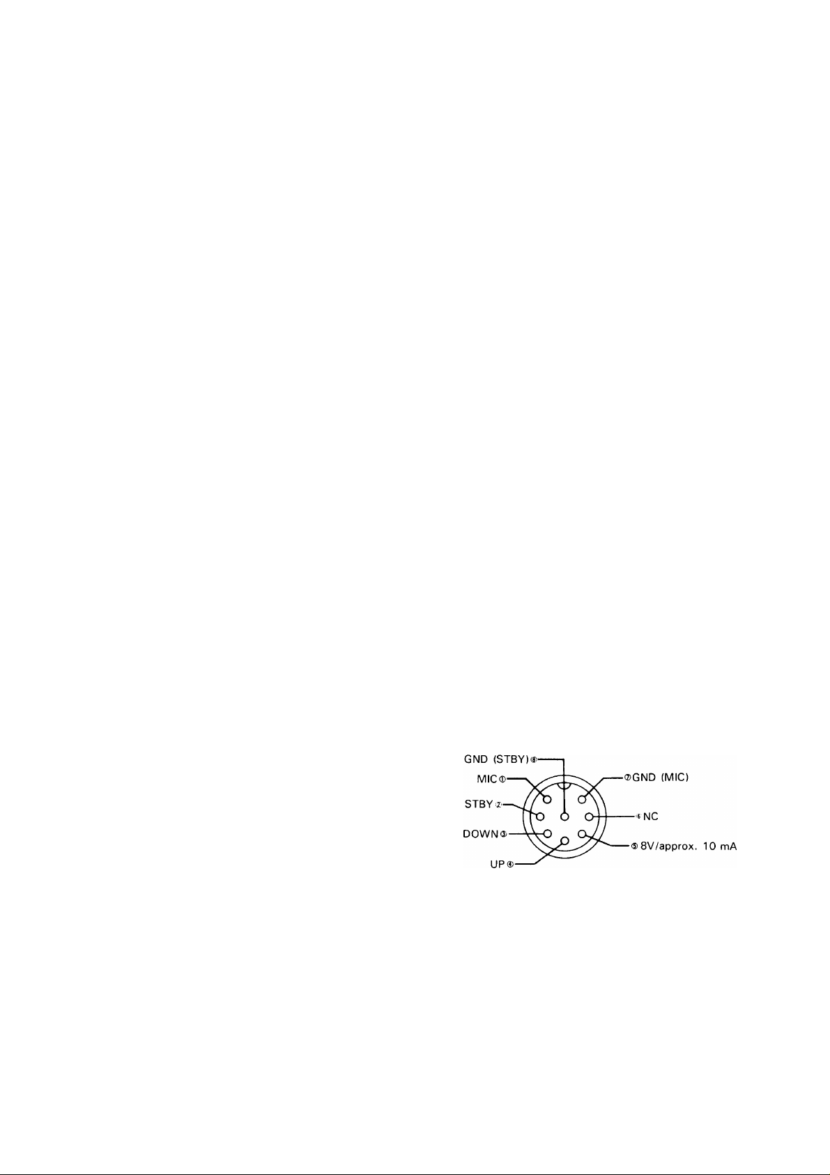
MIC jack
Connector for a microphone.
MIC connector (Front view)
@ AT TUNE switch
When this switch is turned ON with the AUTO/THRU
switch is placed in the AUTO position, the automatic
tuner will be engaged and the tuner will try to match
the antenna.
@ AUTO/THRU switch
AUTO: The auto antenna tuner is used in
transmit.
THRU: The auto antenna tuner is not used in
transmit.
8

Standby switch
This switch is used when you want to manually con
trol transmit or receive.
SEND: Places the radio into transmit.
REC: Places the radio into receive.
The Standby switch is also used to clear an entry dur
ing direct entry of VFO frequencies, or when entering
a memory channel.
@ ALC/PWR/SWR meter switch
ALC meter
Used to monitor the drive level in USB, LSB, and AFSK
modes.
PWR meter
Used to indicate the output power. Note that this meter
is a peak reading meter, not an average reading meter.
SWR meter
Used to indicate the Standing Wave Ratio of the an
tenna and feedline connected to the ANT connector
when the AUTO/THRU switch is in the THRU position.
@ ATT (Attenuator) switch
The incoming receive signal level is attenuated by ap
proximately 20 dB when this switch is activated.
When the incoming receive signal is very strong (20
dB over S-9), the signal should be attenuated to pre
vent distortion of the signal, thereby stabilizing the
receiver performance. This is easily done by activat
ing the ATT switch. This control is also useful when
a strong signal is near your desired signal, while some
loss will occur to the desired signal as well as the un
desired signal, the use of the attenuator will sometimes
allow you to complete the QSO.
NB (Noise Blanker) switch
When pulsating noise, such as that caused by automo
bile ignitions is encountered, place the NB switch ON.
This will provide approximately 40 dB’s of attenuation
to this interfering signal. If there is no noise present,
the switch should be in the OFF position. This switch
will not help to eliminate atmospheric or line noises,
only pulse type noise.
VOICE switch
When the optional VS-1 voice synthesizer unit is in
stalled the operating frequency will announced
whenever the VOICE switch is depressed. For a dial
frequency of 14.200.0 the frequency will be an
nounced as: «one», «four», «point», «two», «zero»,
«zero», «zero», «zero».
Please refer to page 28 for installation instructions con
cerning the VS-1 Voice Synthesizer.
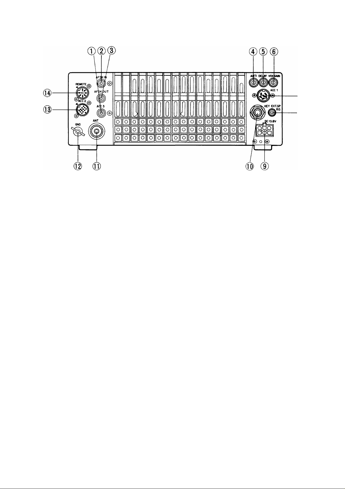
3-1-2. -Rear panel
(T) ACC 3 terminal
Spare RCA type terminal. No internal connections have
been made.
(2) AFSK IN terminal
AFSK input terminal.
AFSK OUT terminal
Constant level AF output terminal for AFSK operation.
® ANTI VOX control
VOX operations are sometimes difficult with high
speaker volume control settings. The ANTI VOX con
trol is used to reduce the tendency of the VOX to acti
vate from inputs from the speaker. The ANTI VOX
control is not active when headphones are connect
ed, for obvious reasons!
-ANTI
vox GAIN control
This control adjusts the sensitivity of the VOX ampli
fier. Adjust this control for your personal preference.
vox GAIN
@ ACC 1 jack
This jack is designed for connection of the 6-pin DIN
connector supplied with the optional interface unit.
(D EXT. SP (External speaker) jack
This jack is for connection of an external speaker.
(9) DC power connector
This is used to connect the DC power supply.
KEY jack
Using shielded line, connect a 1/4″ phone plug to this
jack for CW operation. Open-terminal voltage is approx
imately 5.5 VDC.
® DELAY control
This control adjusts the «hang-time” that the radio will
remain keyed after voice input has stopped.
DELAY
10
(Q) ANT (Antenna) connector
This UHF connector should be attached to a suitable
antenna for transmitting and receiving. The antenna ca
ble should be 50-ohm coax, terminated with a PL-259
connector.
® GND (Ground) terminal
To prevent electric shock, as well as RFI and BCI, con
nect the transceiver to a good earth ground.
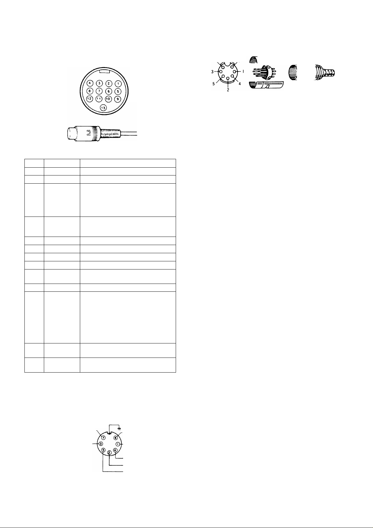
@ ACC 2 jack
Terminal numbers and their applications are as follows:
View from the
rear panel.
Internal wiring
View from cord
7. . ^ 6
3-1-3. Top cover
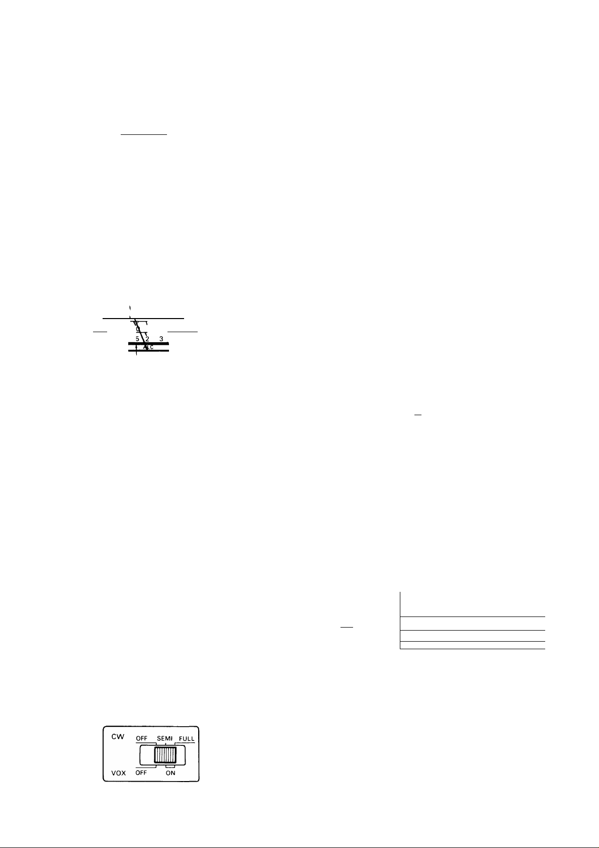
CW OFF SEMI FULL
13-pin DIN plug
Pin No.
1
2 NC
3
4
10 NC
11
12 GND Grounding (The shielded wire of the
13
Pin Name
NC
Data output Output level is fixed regardless of the
GND
5 NC
6
NC
7
NC
8 GND
9
MIC mute
Data input
Standby Standby terminal
No connection
No connection
AF control setting.
Output voltage:
300 mV or more at maximum re
ceiving input with 4.7 kQ load.
Grounding (The shielded wire of the
audio output terminal is connected
here.)
No connection
No connection
No connection
Grounding
Signal input from the MIC jack is mut
ed. Grounding mutes signal.
No connection
Input terminal for data communica
tion. In SSB, MIC gain can be con
trolled by the MIC control.
Input voltage:
500 mV or less
(SSB: Voltage starts deflecting ALC.
FM: Voltage providing ±3.0 kHz
modulation ratio.)
audio input is connected here.)
Grounding transmits.
Application
VOX OFF ON
VOX/BREAK IN switch
VOX (Voice Operated Switch) operation is possible in
LSB, USB, FM or AFSK mode operations. To activate
the VOX circuitry place the VOX switch ON.
This control is also used to select either Full or Semi
automatic break-in.
(Q) REMOTE connector
Note:——————————————————————————
When the control relay is used refer to section 5-8-10.
+ 12 VDC ON transmit
max. 10 mA.
From standby switch
(PTT circuit for foot switch)
GND
ALC input
Speaker output
T
-Ar
Control relay
11
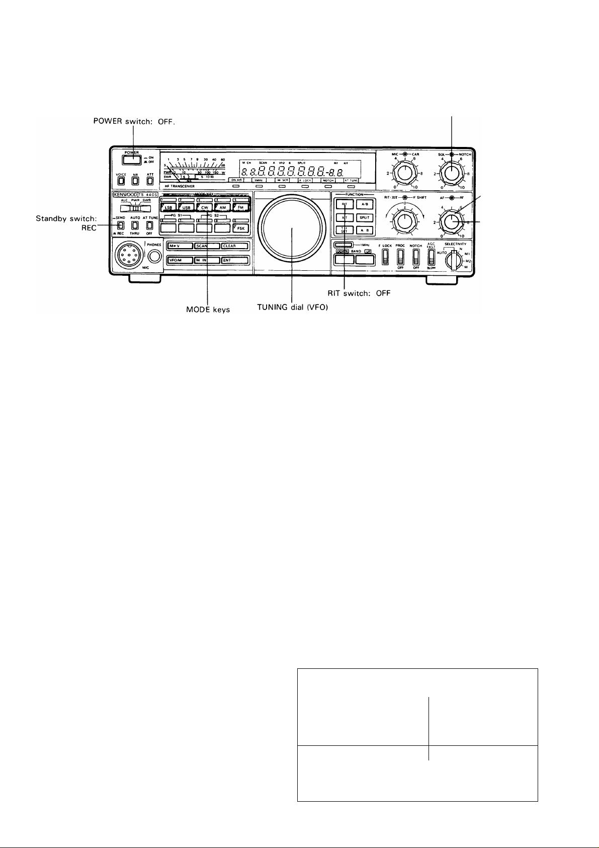
3-2. RECEIVE
SQL control:
Fully counterclockwise.
RF gain control:
, Fully clockwise.
AF gain control:
Fully counter
clockwise.
3-2-1. Initial setting
1. Preset the controls as shown in the accompanying
illustration above.
2. Place the POWER switch to ON. (During fixedstation operation you must first turn ON your DC
power supply, the PS-50 is recommended.)
3. The meter will illuminate and a frequency will ap
pear in the display.
4. Set the BAND switches for the desired band. If you
desire to tune a frequency other than one of the
amateur radio frequencies, place the 1 MHz switch
ON. With the 1 MHz switch ON the UP/DOWN
switches will advance the frequency in 1 MHz
steps, rather than thru the amateur radio bands.
5. Select the desired MODE using one of the mode
switches.
Notes:———————————————————————-
1. By international convention amateur radio fre
quencies below 10 MHz utilize the LSB (Lower
Sideband) mode, and frequencies of 10 MHz
and above use USB (Upper Sideband).
2. The TS-440S automatically selects the normal
mode for you. The exact changeover point is
9.5 MHz. You can override this selection by
pressing the desired mode switch.
3-2-2. CW zero-beat operation
Zero-beat operation with a station during CW mode
operation
1. Set the RIT/XIT switches to OFF.
2. When an optional filter is not used, tune the TUN
ING dial so that the receive beat frequency is ap
proximately 800 Hz. You can check this by turning
the VOX OFF, and then closing your CW key. Then
by using the sidetone oscillator, and the incoming
receive signal you can zero-beat by turning the
TUNING dial until the two tones are the same fre
quency.
3. When the YK-88C filter is used the simplest method
to use is to adjust the TUNING dial for a maximum
S-meter deflection.
Reception at the desired pitch after zero-beat
operation.
1. After zero-beating turn the RIT switch ON, and ad
just the RIT control for the desired pitch.
2. Adjust the IF SHIFT control for the strongest sig
nal level.
6. Adjust the AF gain control for the desired volume.
7. Slowly rotate the TUNING dial until the desired sig
nal can be heard clearly.
8. The desired receive frequency can also be entered
directly by using the numeric keypad. For details
of this operation please refer to the “Direct key
board frequency entry» section on page 13.
12
Your frequency
Receiver carrier frequency
(BFO) 1
Tuning for CW Operation
Displayed frequency
1
Transmit-Receive frequency
(Displayed frequency)
1
1
800Hz
Beat note

3-2-3. Direct keyboard frequency entry
Direct keyboard entry of the frequency is possible us
ing the numeric keypad on the TS-440S. This allows
rapid changes in frequency without the delays encoun
tered when using other tuning methods.
1. Select the VFO mode.
2. Press the ENT key. The display will indicate
3. Enter the desired operating frequency from Most
Significant Digit to the Least Significant Digit. You
do not have to enter trailing zeros, but you must
enter a leading zero for frequencies between 1 and
3.99999 MHz or two leading zeros for frequencies
between 0.1 and 0.99999 MHz. (03.500.00 MHz).
A VFO
D C
_/. _/
4. After the last digit has been entered press the ENT
key again to signify you want the radio to change
frequency. If you entered the frequency down to
the nearest 10 Hz a beep will sound and the radio
will automatically change to the new frequency
without the need of pressing the ENT key for the
second time.
3-2-4. AM reception
There are cases during AM broadcast reception, where
interference in noticeable when SELECTIVITY is W, but
the intelligibility is poor with the radio in the M2 posi
tion, due to a lack of high frequency response. If this
condition occurs place the SELECTIVITY switch to M2
and rotate the TUNING dial +/- 1 kHz from the center
frequency. It should be possible to find a point where
the interference will be a little greater, intelligibility
should be improved.
Another method utilizes the execellent receiver stabil
ity of the TS-440S by selecting USB or LSB and tun
ing to one of the sidebands of the AM signal. The only
disadvantage to this method is that a 5 Hz beat tone
might be detected along with the desired receive signal.
3-3. TRANSMIT
3-3-1. SSB (USB, LSB) mode
1. Set the MODE keys to USB or LSB. By internation
al convention frequencies below 10 MHz utilize the
LSB (Lower Sideband) mode, and frequencies
above 10 MHz use USB (Upper Sideband). The ac
tual switchover point on the TS-440S is 9.5 MHz.
The TS-440S will select the proper mode when you
tune to the desired frequency. You can override this
by simply pressing the desired mode key.
2. Set the Meter switch to ALC.
ALC PWR SWR
I\. 1
un
I U I I li I I I I
I
/.
u u u. u
For example: To enter 14.200.00 MHz there are
two methods:
Method one: Press [ENT], [1], [4], [2], [ENT].
Method two: [ENT], [1], [4], [2], [0], [0], [0], [0].
I U D I I I I I I
I
/. /_
u u. u
Note:——————————————————————
Attempting to enter a frequency outside the tun
ing range of the radio will cause the display to return
to » . .
If you make a mistake while entering the frequen
cy and have not yet pressed the ENT key, or en
tered the final digit, you may cancel the input by
pressing either the CLEAR key or standby switch.
——
3. Press the microphone PTT switch, or set the Stand
by switch from REC to SEND.
4. Speak into the microphone and adjust the MIC gain
control so that the meter deflection does not ex
ceed the ALC zone on voice peaks.
Note:——————————————————————————
Adjustment using the ALC meter provides greater ac
curacy than if you try and use the power meter for ad
justment. Never adjust for ALC deflection above the
ALC zone, as this will cause distortion of the transmit
ted audio signal.
1 3 5 7 9 20 40 60
S \\\\\\\lf / / / ///b
——
PWR 0 10
SWR 1 1.5
Note:
——————————————————————
Do not exceed the ALC zone on voice peaks.
-V
ALC zone
I 11111/—ry
50 100 150 W
5 10 00
————
13
3-3-2. CW mode
Set MODE keys to CW and set the Meter switch to
ALC.
ALC PWR SWR
^ 1 /———
in
Placing the Standby switch to send and depressing the
CW key will cause the radio to transmit.
Transmission is also possible when in the SEMI or FULL
break-in mode by simply depressing the key, with the
Standby switch in the REC position.
Adjust the CAR control until the meter deflection is
within the ALC zone.
7 9 20 40 60
s \ \ N V \ \ \ \ i l / / / / / A
PWR 0 1
SWR 1 1.5
ALC zone
• SEMI and FULL break-in
Two break-in methods are provided with the TS-440S
transceiver, SEMI and FULL break-in. With either break-
in operation depressing the CW key will cause the ra
dio to transmit without the need for manually switch
ing the SEND/REC switch. The difference between
FULL and SEMI break-in is that during FULL break-in
operation it is possible to listen between dots and dash
es, and that during SEMI break-in it is not.
Note:——————————————————————————
With either SEMI or FULL break-in operation, cross
band/cross mode operation is not possible. Addition
ally, when you are using FULL break-in operation you
should not work cross band splits, only in the same
band.
The TS-440S also provides a side-tone oscillator cir
cuit to allow monitoring of your CW signal during trans
mission.
(a) Semi-automatic break-in
Depressing the CW key will automatically place the
transceiver into the transmit mode. Transmit mode
will be maintained for a period determined by the
setting of the VOX DELAY control on the rear panel
of the transceiver, even after the CW key is
released.
1—rjnin—T7″
50 100 150 W
5 10 00
(b)
Full-automatic break-in
Depressing the CW key will automatically place the
transceiver into the transmit mode. Releasing the
CW key will return the radio to receive immediately
enabling reception between characters.
Caution: ——————————————————————
The TL-922A/922 linear amplifer is not designed
for full break-in type operation. Attempting to use
this accessory in the FULL break-in mode cause
damage to occur to the linear amplifier.
CW OFF SEMI FULL
VOX OFF
On occasion an electronic keyer may be used that
has no method of producing a continuous trans
mit condition. In order to obtain a continuous car
rier for tuning simply place the Standby switch to
the SEND position.
3-3-3. FM mode
Select the desired frequency within the 28 MHz
amateur radio band. Place the MODE key to FM and
the Meter switch to ALC.
ALC PWR SWR
\ I
ZEL
Press the microphone PTT switch or place the Stand
by switch to SEND.
Adjust the CAR control until the meter deflection is
within the ALC zone. This will provide full power in the
FM mode.
To decrease the power, place the Meter switch to PWR
and while observing the meter rotate the CAR control
counterclockwise until the desired output level is ob
tained.
1 3 5 7
9 20 40 60
ALC PWR
SWR
1 /•
s ‘^\\\\\
PWR 0 V 10
SWR ‘l \5 2
ALC zone
Notes:————————————————————————-—
1. The FM power output may fluctuate if running less
than full output.
2. Ensure that an antenna with a low SWR is used.
The TS-440S provides several protection circuits,
continually loading into an antenna with a high SWR
(3 to 1 or greater) will eventually cause damage to
the final amplifiers.
3. The PWR meter reading may not be accurate with
high SWR values. Use a good antenna for the most
accurate readings.
1 i / / / / / /dB
V 1
\+aLC
Ì II II// 1 /
50 100 150 W
3 5 10 00
14

• Subaudible tone
An optional subaudible tone unit TU-8 is available for
installation in the TS-440S for accessing 10 meter FM
repeaters. This tone is activated whenever the
TS-440S is in the SPLIT mode.
3-3-4. AM mode
1. Set the Meter switch to PWR.
2. Set the MODE key to AM.
3. Place the Standby switch to SEND.
4. Adjust the CAR control so that the meter indicates
25 watts.
5. Place the Meter switch to ALC.
6. Adjust the MIC gain control so that the meter
deflection does not exceed ALC zone on voice
peaks.
3-5-1. Why two VFO’s
Occasionally DX stations will utilize an operational
procedure known as split frequency operation. When
the DX station is in this mode he will be transmitting
on one frequency and receiving on another. This is
done in order for the DX station to be able to recog
nize the calls of stations during pile-ups.
Older transceivers required the use of an external VFO
to allow this split frequency operation. The TS-440S,
thru the use of microprocessor controls, effectively pro
vides two separate VFOs in the same package. Several
different controls and switches have been provided to
increase the operators convenience when faced with
this type of operation. The use of these controls is dis
cussed below.
3-4. AUTOMATIC ANTENNA TUNER
(The AT unit AT-440 is required for
this function.)
The automatic antenna tuner operates within the
amateur radio bands from 3.5 thru 29.7 MFIz.
1. Ensure that an antenna designed for use within the
band you intend to operate on is properly connect
ed to the antenna terminal.
2. Set the AUTO/THRU switch to the AUTO position.
3. Place the AT TUNE switch to the ON position. The
AT TUNE indicator will light and the tuner will be
gin tuning. Then the CW mode indicator will light.
4. After a short period the AT TUNE indicator will go
OFF and the motors will stop turning.
5. Place the AT TUNE switch to OFF.
6 . Tuning is now completed. You may now carry out
normal communications.
Notes:
—————————————————————————
1. When the AT TUNE switch is ON and the AT indi
cator lights but then goes out immediately it is an
indication that the antenna was not that far off
resonance and that tuning has been completed.
2 . Normal operation is not possible until the AT TUNE
switch has been turned OFF.
3 . If the motors do not stop turning after approximately
30 seconds, place the AT TUNE switch to OFF, and
then back to ON again. The tuner will attempt to
tune again, and should find a good match. If the
tuner will not stop after several tries it indicates
some problem exists with the antenna system.
Readjust the antenna and feedline before attempt
ing to tune again.
3-5-2. Split frequency
(a) A = B switch
Depressing this switch causes the data contained
in the inactive VFO (the VFO that is not currently
being displayed) to change to the same data con
tained in the active VFO (the one currently dis
played). Both the frequency and mode are
changed.
For example: VFO A is set at 7 MHz in LSB, and
VFO B is 21 MHz in USB. VFO A is the active VFO
(show on the display). Depressing the A = B switch
will cause VFO B to change to 7 MHz in LSB.
(b) A/B switch
Allows selection of the desired active VFO. Each
time this switch is depressed the active VFO will
alternate between VFO A and VFO B.
(c) SPLIT switch
Allows the use of one VFO for transmit, and the
other for receive (Split Frequency operation). For
example: VFO A is the active VFO, and VFO B is
the inactive VFO. Depressing the SPLIT switch will
cause the TS-440S to receive on VFO A and trans
mit on VFO B. The mode of reception and trans
mission will follow the mode contained in the
appropriate VFO memory. It is possible to work
cross band, cross mode if desired.
To avoid confusion during contest, or pile-up oper
ations we recommend using VFO A for receive and
VFO B for transmit.
(d) T-F SET switch
Depressing this switch will allow you to rapidly set
or check the transmit frequency, during SPLIT
operations, without the need of actually trans
mitting.
3-5. DUAL DIGITAL VFO’s
Operational convenience can be enhanced thru the use
of both VFO A and VFO B.
This switch is especially convenient when you are
trying to locate the transmit frequency of the sta
tion currently in contact with the DX station, since
15

depressing this switch allows you to receive on the
transmit frequency as long as the switch is held
depressed. The TUNING dial is active when this
switch is depressed, so it is easy to change your
transmitter frequency at the same time, if neces
sary. Releasing the switch will return you to the
original receive frequency.
3-6. MEMORY
The TS-440S incorporates a convenient 100 channel
memory that can be used to store and recall common
ly used frequencies. These channels can be subdivid
ed into 10 user-defined groups to tailor the TS-440S
for optimum operation in a particular application. You
can, for instance, assign channels 10 through 19 to
the 160 meter band, channels 20 through 29 to the
80 meter band, channels 30 through 39 to the 40
meter band (LSB), channels 40 through 49 to the 20
meter band (USB), channels 50 through 59 to the 1 5
meter band, channels 60 to 69 to the 10 meter band
(FM), channels 70 through 79 to the 12 meter band,
and channels 80 through 89 to various shortwave
bands. Channels 90 through 99 could then be assigned
as split frequency channels. After completing channel
assignments, you can then use the convenient memory
scan function to automatically recall the stored fre
quencies on a group basis.
b. Enter a two digit channel number using the nu
meric keypad, being sure to include the leading
zero for channels 00 through 09. Pressing the
CLEAR key or the standby switch before press
ing the second digit will return you to the origi
nal channel.
A VFO
1 U 1
/ /. /
1 J.U
c n
c. Use the UP/DOWN switches and/or microphone
UP/DOWN switches to scroll thru the different
memory positions.
5. When the desired memory channel is displayed,
press the M.IN key again. The current frequency
and mode will be stored, the scroll mode will be
cancelled, and the TS-440S will return to the oper
ating mode and frequency that was displayed be
fore the M.IN key was pressed initially. Note that
if RIT was selected prior to step 2, the actual fre
quency stored will be the indicated frequency plus
or minus the RIT variable.
3-6-2. Transferring memory information to the VFO.
1. Press the VFO/M key to select the memory mode.
3-6-1. Memory Entry
1. With the TS-440S in the VFO mode, select the
desired operating frequency and mode as described
in previous sections.
A VFO
‘ U 1
1 /. /
c n
1 J.U
2. Press the M.IN switch. The radio will enter the
Memory Scroll (M.SCR) mode. The current memory
channel number (M.CH), frequency and mode will
be displayed, but the actual operating frequency
and mode will remain unchanged allowing uninter
rupted reception.
n n
u u
3. Select the desired memory channel using one of the
three methods described below,
a. Turn the TUNING dial until the desired channel
number is displayed (One revolution of the dial
cover about 10 channels).
I U / “7 C n
<_ -I
I I. I I J.IJ
2. Select a channel using any of the methods dis
cussed under the Memory Entry section.
r n -J O U i~l n I I
O o
/_ /_/.
u u u. u
Press the M^V key. The stored data will be trans
ferred to the active VFO allowing you to begin tun
ing from that point. The TS-440S automatically
returns to the VFO mode when the M^V key is
depressed.
A VFO
D O O n n
L U. U U U. U
Notes:———————————————————————
——-
1. The RIT/XIT status will be copied from the memory
to the VFO when the M^V key is depressed.
2. When data is transferred from the split frequency
memory, the active VFO is loaded with the receive
data and the inactive VFO will be loaded with the
transmit data. The TS-440S will then automatical
ly enter the SPLIT mode.
3. This operation will not function if no data is con-
16
Loading…
- Addeddate
- 2021-01-13 02:50:36
- Identifier
- manualzz-id-1043647
- Identifier-ark
- ark:/13960/t9z133v8r
- Ocr
- tesseract 5.3.0-3-g9920
- Ocr_autonomous
- true
- Ocr_detected_lang
- la
- Ocr_detected_lang_conf
- 1.0000
- Ocr_detected_script
-
Latin
Cyrillic
Arabic
- Ocr_detected_script_conf
-
0.4963
0.4808
0.0184
- Ocr_module_version
- 0.0.21
- Ocr_parameters
- -l srp+kir+eng+que+rus+kaz+bul+mon+lat+Cyrillic+Latin+Arabic
- Page_number_confidence
- 74
comment
Reviews
There are no reviews yet. Be the first one to
write a review.
161
Views
DOWNLOAD OPTIONS
Temporarily Unavailable
DAISY
For users with print-disabilities
Temporarily Unavailable
EPUB
Uploaded by
chris85
on
Скачать файл PDF «Kenwood TS-440S Руководство по эксплуатации» (45.29 Mb)
Популярность:
2379 просмотры
Подсчет страниц:
57 страницы
Тип файла:
Размер файла:
45.29 Mb
Google Ads:
- Главная
-
Kenwood
-
Аудио
-
TS-440S
-
Руководство по эксплуатации
Вы можете бесплатно скачать Руководство по эксплуатации для Kenwood TS-440S.
Также вы сможете прочесть онлайн этот документ без скачивания.
Скачать Руководство по эксплуатации для Kenwood TS-440S
Тип файла
PDF
Размер
45.29 Mb
Кол-во страниц
57
Просмотров
2379
Вы не робот?
60
Скачать файл:
kenwood-ts-440s-owner-s-manual.pdf
Читать онлайн Руководство по эксплуатации для Kenwood TS-440S (Страница 1)

Next →
- 1
- 2
- 3
- 4
- 5
- 6
- 7
- 8
- 9
- 10
- 11
- 12
- 13
- 14
- 15
- 16
- 17
- 18
- 19
- 20
- 21
- 22
- 23
- 24
- 25
- 26
- 27
- 28
- 29
- 30
- 31
- 32
- 33
- 34
- 35
- 36
- 37
- 38
- 39
- 40
- 41
- 42
- 43
- 44
- 45
- 46
- 47
- 48
- 49
- 50
- 51
- 52
- 53
- 54
- 55
- 56
- 57
Другие Аудио Kenwood TS-440S
Топ Kenwood Аудио
-
DPX500BT Руководство пользователя
PDF файлов
2Просмотров
5389 -
KDC-9015 Руководство пользователя
PDF файлов
2Просмотров
3066 -
KDC-X815 Руководство пользователя
PDF файлов
2Просмотров
2659 -
KDC-9017 Руководство пользователя
PDF файлов
2Просмотров
3035 -
KDC-X717 Руководство пользователя
PDF файлов
2Просмотров
2785 -
KDC-X817 Руководство пользователя
PDF файлов
2Просмотров
2761
Ранее вы смотрели
Производители
Amped Wireless
Beyond
CTX
Global Upholstery Co.
McDATA
Omnimount
ROUTE 66
UMA Enterprises
Wasp Bar Code
WS-Spalluto
Типы устройств
Лодки
Тепловые пушки
Роутеры Bay Router Series
Стекловолоконные интерфейсы с широкополосной передачей данных
Ручные блендеры
Комплекты гайковертов
Переформованные мембраны
Лебедки
NEW QUINTA ECO PLUS
Оверлоки
Устройства
Carvin SH275
Garmin MAP 235
Hatteras Hammocks Hammock Caddy
IDEAL INDUSTRIES Door MX
Makita 5094DWA
Philips AZ9355/00
Stow cs403020
Tecumseh HGA5492EXA
freeuserguide.ru
About Us
Contacts
Disclamers
Privacy Policy
Эта страница полезна для вас? Поделитесь ссылкой: