
В этой статье мы поговорим про то, как собрать квадрокоптер на Ардуино. Это не самая простая, хотя и очень увлекательная задача, результатом решения которой станет появление небольшого беспилотника, спроектированного, собранного, и настроенного собственными руками. Сразу оговоримся, что речь идет о максимально дешевом дроне из наиболее доступных по цене комплектующих.
Помимо микроконтроллера, нам понадобятся:
- Аккумулятор (лучше несколько) на 3.7В
- Плата MPU-6050 (на ней установлены гироскоп и акселерометр)
- Транзистор ULN2003A
- Коллекторные двигатели с полым ротором 0820
- Провода
Необходимо сделать несколько замечаний. Так как мы собираем дешевый самодельный дрон, то наш выбор пал на коллекторные движки с полым ротором (так называемые coreless motors). Они далеко не так надежны, как бесколлекторные двигатели, но зато гораздо дешевле стоят. Кроме того, можно обойтись без дополнительных контроллеров скорости.
Зато невозможно обойтись без гироскопа и акселерометра. Гироскоп необходим для того, чтобы квадрокоптер мог удерживать заданное направление движения, тогда как акселерометр используется для измерения ускорения. Без этих устройств управлять коптером было бы гораздо сложнее (если вообще возможно), так как именно они предоставляют данные для сигнала, регулирующего скорость вращения винтов.
Мы не указали в списке необходимых деталей раму. Ее можно приобрести, а можно распечатать на 3D принтере каркас, лучи и крепления для двигателей. Второй вариант нам кажется более предпочтительным, тем более, что в интернете можно без труда найти проекты квадрокоптера.
Как напечатать раму и крепеж
3D принтеры можно найти во многих университетах, лабораториях, коворкингах. Зачастую доступ к ним бесплатный. Модели для печати можно создать самостоятельно, используя для этого, например, Solidworks. А можно воспользоваться уже готовыми решениями, при необходимости изменив параметры.
Как настроить акселерометр гироскопа
Для настройки акселерометра-гироскопа (I2C)мы рекомендуем использовать следующую библиотеку. Ни в коем случае не подключайте плату к напряжению 5В, иначе вы моментально ее испортите.
Вкратце расскажем, чем интересна плата I2C с датчиками. Она заметно отличается от обычной платы акселерометра с тремя аналоговыми выходами для осей X, Y, Z. I2C представляет собой интерфейсную шину, обеспечивающую передачу значительных объемов данных через логические цифровые импульсы.
Аналоговых выходов на плате не много, и в этом большой плюс I2C, ведь в противном случае нам бы пришлось использовать все порты на Arduino, чтобы получить данные от гироскопа и акселерометра.
Схема подключения к Arduino
Прежде чем плата I2C сможет обмениваться данными с Arduino, ее необходимо подключить к контроллеру.
Схема следующая:
- VDD -3.3v
- GND — GND
- INT- digital 2
- SCL — A5
- SDA — A4
- VIO – GND
Еще раз обращаем внимание на то, что для питания необходимо использовать необходимо именно 3.3В. Подключение платы к 5В скорее всего приведет к ее поломке (спасти может только регулятор напряжения, но он далеко не всегда присутствует на плате).
Если на плате присутствует контакт AD0, он подключается к земле (GND).
В библиотеке, на которую мы дали ссылку выше, используются перечисленные каналы.
Скетч для Arduino
Преимуществом выбранного для сборки дрона микроконтроллера является относительная простота работы с ним. Вам не придется читать специальные книги, документы и техническую документацию. Достаточно знать основы программирования Arduino, которые, как вы сейчас убедитесь, не так сложны.
Подсоединив плату MPU-6050 к контроллеру, включите его и перейдите по ссылке.
Нас интересует скетч I2C scanner code, вернее, его код.
Скопируйте программный код, вставьте в пустой скетч, после чего запустите его. Убедитесь, что подключение установлено к 9600 (для этого запустите Arduino IDE через Tools-Serial Monitor). Должно появиться устройство I2C с адресом 0х68 либо 0х69. Запишите или запомните адрес. Если же адрес не присвоился, скорее всего проблема в подключении к электронике Arduino.
Затем нам понадобится скетч, умеющий обрабатывать данные гироскопа и акселерометра. В интернете есть множество вариантов, и найти подходящий не проблема. Скорее всего, он будет в заархивированном виде. Разархивируйте скачанный архив, отройте Arduino IDE и добавьте библиотеку (sketch-import library-add library). Нам понадобятся папки MPU6050 и I2Cdev.
Открываем MPU6050_DMP6 и внимательно просматриваем код. Никаких сложных действий производить не придется, но если был присвоен адрес 0х60, то необходимо расскоментировать строку в верхней части (ее можно найти за #includes) и написать верный адрес. Изначально таv указан 0х68.
Загружаем программу, открываем окно монитора через 115200 и просто следуем инструкции. Через несколько мгновений вы получите данные с гироскопа/акселерометра. Затем следует провести калибровку датчиков.
Установите плату на ровную поверхность и запустите скетч MPU6050_calibration.ino (легко ищется в интернете). Просмотрите код, по умолчанию в нем указан адрес 0х68. После запуска программы у вас появится информация по отклонениям (offset). Запишите ее, она нам понадобится в скетче MPU6050_DMP6.
Все, вы получили функционирующие гироскоп и акселерометр.
Программа для Arduino
По ссылке вы сможете скачать программу для Arduino, с помощью которой коптер будет стабилизирован в полете и сможет зависнуть над землей. В дополнение к программе обязательно скачайте библиотеку с Arduino PID по ссылке.
Программа поможет вам управлять дроном. Алгоритм, используемый для стабилизации, основан на двух PID-контроллерах. Один предназначен для крена, другой – для тангажа.
Разница в скоростях вращения пары винтов 1 и 2 равна разнице в скоростях пары винтов 3 и 4. Тоже самое справедливо и для пар 1, 3 и 2, 4. PID-регулятор производит изменение разницы в скорости, после чего крен и тангаж становятся равными нулю.
Обратите внимание на цифровые пины Arduino для моторов и не забудьте изменить скетч.
Подключение к контроллеру
Для того, чтобы управлять коптером, нам необходимо получить контроль над моторами, подключив их к Arduino. Контроллер дает на выходе лишь небольшое напряжение и силу тока, поэтому подключение двигателей напрямую лишено смысла. Вместо этого можно поставить несколько транзисторов, позволяющих увеличить напряжение.
Для составления схемы нам необходимы:
- Arduino
- Двигатели
- Транзисторы
Все это собирается на монтажной плате и соединяется коннекторами.
На первом этапе следует подсоединить 4 ШИМ выхода (обозначены ~) к транзистору. Затем подсоедините коннекторы к движкам, подключенным к питанию. В нашем случае мы используем аккумулятор на 5В, но подойдет и аккумулятор на 3-5В.
Транзисторы должны быть заземлены, а земля на плате Arduino должна быть подключена к земле аккумулятора. Двигатели должны вращаться в правильном направлении, то есть работать на подъем коптера, а не на его крен.
Переключив контакт двигателя с напряжения 5В на транзистор, вы увидите, что ротор изменит направление вращения. Единожды совершив настройку, больше возвращаться к изменению направления вращения ротора не придется. Теперь нас интересует скорость.
Запустив и проверив акселерометр, мы устанавливаем нашу схему на ProtoBoard. За ее неимением, можно использовать и обычную монтажную плату, предварительно напаяв на ней рельсы для контроллера.
Перед тем, как припаивать акселерометр к плате, необходимо выполнить его калибровку на горизонтальной поверхности. Это поможет добиться более точной работы сенсора в будущем.
Как еще можно модернизировать квадрик
Узким местом коптера являются его коллекторные движки. Если поискать, можно найти чуть более крупные и более мощные моторы, чем предложены в нашей статье, но значительного выигрыша в характеристиках не произойдет.
Впрочем, у нас была цель собрать недорогой квадрокоптер своими руками, и именно поэтому использовались дешевые моторы. Бесколлекторные двигатели заметно дороже, но зато они дадут вам заметно большую мощность и надежность. К ним придется докупить еще и контроллеры скорости, но это действительно эффективная модернизация.
Выбор платы Arduino Uno обусловлен тем, что с нее можно довольно легко снять чип и поставить его на ProtoBoard. Это позволяет уменьшить вес дрона на 30 грамм, но придется включить в схему дополнительные конденсаторы. Подойдет и плата Arduino Pro Mini.
Что касается программы Arduino, то ее можно сравнительно легко изменить и дополнить новыми функциями. Главное, что с ее помощью дрон способен в автоматическом режиме стабилизовать свое положение.
На квадрокоптер могут быть установлены дополнительные модули, например, плата приемника, что позволит организовать дистанционное управление дроном.
На этом мы завершаем статью о создании беспилотника на Arduino. Подписывайтесь на наши обзоры и делитесь полезными материалами в социальных сетях. До новых встреч.
Дата: 2023-07-23 Автор: https://drongeek.ru/profi/kvadrokopter-na-arduino Просмотров: 4893

Здравствуйте, хаброжители!
В этой серии статей мы с вами приоткроем крышку квадрокоптера чуть больше, чем этого требует хобби, а также напишем, настроим и запустим в воздух собственную программу для полетного контроллера, которым будет являться обычная плата Arduino Mega 2560.
У нас впереди:
- Базовые понятия (для начинающих коптероводов).
- PID-регуляторы с интерактивной web-демонстрацией работы на виртуальном квадрокоптере.
- Собственно программа для Arduino и настроечная программа на Qt.
- Опасные тесты квадрокоптера на веревке. Первые полёты.
- Крушение и потеря в поле. Автоматический поиск с воздуха средствами Qt и OpenCV.
- Окончательные успешные тесты. Подведение итогов. Куда дальше?
Материал объемный, но постараюсь уложиться в 2-3 статьи.
Сегодня нас ожидает: спойлер с видео, как наш квадрокоптер полетел; базовые понятия; PID-регуляторы и практика подбора их коэффициентов.
Зачем все это?
Академический интерес, который, кстати, преследует не только меня (1, 2, 3). Ну и, конечно же, для души. Я получил огромное удовольствие во время работы и ощутил настоящее непередаваемое счастье, когда «ЭТО» полетело с моей программой 
Для кого?
Данный материал может быть интересен в том числе и людям, которые далеки, или пока только собираются заняться мультироторными системами. Сейчас поговорим про назначение основных узлов квадрокоптера, про то, как они взаимодействуют между собой, про основные понятия и про принципы полёта. Конечно, все знания, которые нам потребуются, можно найти в сети, но нельзя же заставлять выискивать их на просторах необъятного интернета.
Без ущерба для понимания в базовых понятиях смело пропускайте все, что вам известно, до следующего незнакомого термина, выделенного жирным, или до непонятной иллюстрации.
НЕТ №1!
Не беритесь писать собственную программу для полетного контроллера, пока не попробуете готовые решения, которых сейчас достаточно много (Ardupilot, MegapirateNG, MiltiWii, AeroQuad и т.п.). Во-первых, это опасно! Чтобы управлять квадрокоптером без GPS и барометра нужна практика, а тем более, когда он глючит, переворачивается, летит не совсем туда, куда надо — а этого почти не избежать во время первых тестов. Во-вторых, вам будет во много раз легче программировать понимая, что нужно программировать и как оно должно работать в итоге. Поверьте: математика полета — лишь малая часть кода программы.
НЕТ №2!
Не беритесь писать собственную программу для полетного контроллера, если вас не преследует академический интерес и вам нужно только то, что уже давно умеют готовые решения (летать, фотографировать, снимать видео, летать по заданию и т.п.) Пока вы сами все напишите, пройдет немало времени, даже если вы не один.
Базовые понятия
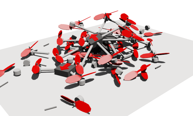
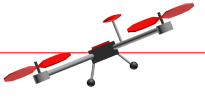
Квадрокоптеры бывают разные, но всех их объединяют четыре несущих винта:
Не смотря на кажущуюся симметрию, пилоту очень важно различать, где у квадрокоптера перед (показан стрелкой). Здесь, как у радиоуправляемых моделей автомобилей: при команде «вперед» квадрокоптер летит не туда, куда смотрит пилот, а туда, куда направлен воображаемый нос квадрокоптера. Это таит в себе опасность: новичкам бывает трудно вернуть к себе подхваченный ветром аппарат, развернутый как-нибудь боком (мы, конечно, не говорим про полеты по камере от первого лица и про «умные» режимы полета с использованием компаса и GPS.) Решению этой проблемы частично могут помочь передние винты или лучи другого цвета, какой-нибудь шарик спереди или разноцветные светодиоды. Но все это оказывается бесполезным, когда пепелац стремительно превращается в точку над горизонтом.
Мы будем летать на раме квадрокоптера формы «X», потому что она мне больше нравится внешне. У каждой конструкции свои плюсы и свое предназначение. Кроме квадрокоптеров есть и другие мультикоптеры. Даже если не считать экзотические варианты, все равно их видов — целая куча!
Разберемся, как наш квадрокоптер устроен внутри, и чем же должен заниматься полетный контроллер, который мы планируем программировать.
Углы тангажа, крена и рыскания (pitch, roll, yaw) — углы, которыми принято определять и задавать ориентацию квадрокоптера в пространстве.
Иногда слово «угол» опускают и просто говорят: тангаж, крен, рыскание. Но согласно Википедии это не совсем точно. Полет квадрокоптера в необходимом направлении достигается изменением этих трех углов. Например, чтобы полететь вперед квадрокоптер должен наклониться за счет того, что задние моторы закрутятся чуть сильнее передних:
Газ квадрокоптера — среднее арифметическое между скоростями вращения всех моторов. Чем больше газ, тем больше суммарная тяга моторов, тем сильнее они тащат квадрокоптер вверх (НЕ ВПЕРЕД!!! «Тапок в пол» здесь означает наискорейший подъем). Обычно измеряется в процентах: 0% — моторы остановлены, 100% — вращаются с максимальной скоростью. Газ висения — минимальный уровень газа, который необходим, чтобы квадрокоптер не терял высоту.
Газ, тангаж, крен, рыскание — если вы можете управлять этими четырьмя параметрами, значит вы можете управлять квадрокоптером. Их еще иногда называют каналами управления. Если вы приобрели двухканальный пульт, с квадрокоптером вам не совладать. Трехканальный скорее подойдет для маленьких вертолетов: без управления креном летать можно, но на квадрокоптере — не удобно. Если вы хотите менять режимы полета, придется раскошелиться на пятиканальный пульт. Хотите управлять наклоном и поворотом камеры на борту — еще плюс два канала, хотя профессионалы используют для этого отдельный пульт.
Режимов полета существует много. Используется и GPS, и барометр, и дальномер. Но мы хотим реализовать базовый — режим стабилизации (stab, stabilize, летать в «стабе»), в котором квадрокоптер держит те углы, которые ему задаются с пульта не зависимо от внешних факторов. В этом режиме при отсутствии ветра квадрокоптер может висеть почти на месте. Ветер же придется компенсировать пилоту.
Направление вращения винтов выбирается не случайно. Если бы все моторы вращались в одну сторону, квадрокоптер вращался бы в противоположную из-за создаваемых моментов. Поэтому одна пара противостоящих моторов всегда вращается в одну сторону, а другая пара — в другую. Эффект возникновения моментов вращения используется, чтобы изменять угол рыскания: одна пара моторов начинает вращаться чуть быстрее другой, и вот уже квадрокоптер медленно поворачивается к нам лицом (ужас какой):
- LFW — left front clockwise rotation (левый передний, вращение по часовой стрелке)
- RFC — right front counter clockwise rotation (правый передний, вращение против часовой стрелке)
- LBC — left back counter clockwise rotation (левый задний, вращение против часовой стрелке)
- RBW — right back clockwise rotation (правый задний, вращение по часовой стрелке)
Скоростью вращения моторов управляет полетный контроллер (контроллер, мозги). Обычно это небольшая плата или коробочка с множеством входов и выходов. Существует огромное количество различных контроллеров с разным набором возможностей, разными прошивками, разными задачами. Вот лишь некоторые:

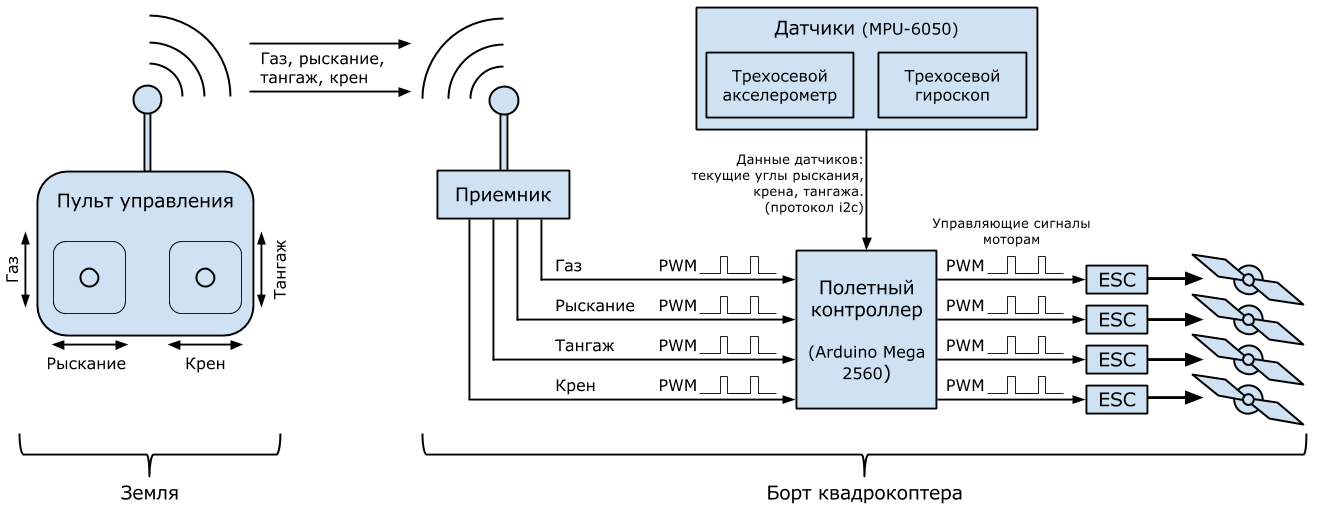
Обобщенной задачей полетного контроллера является несколько десятков раз в секунду выполнять цикл управления в который входит: считывание показаний датчиков, считывание каналов управления, обработка информации и выдача управляющих сигналов моторам, чтобы выполнять команды пилота. Именно это мы и собираемся запрограммировать.
Различных видов датчиков, которые можно задействовать, очень много. Мы будем использовать ставшие уже почти обязательными во всех квадрокоптерах трехосевой гироскоп и трехосевой акселерометр. Акселлерометр измеряет ускорение, гироскоп измеряет угловую скорость. Благодаря им полетный контроллер узнает текущие углы тангажа, крена и рыскания. Эти датчики бывают встроенными в полетный контроллер, а бывают внешними. Процесс вычисления трех углов по показаниям датчиков — тема для отдельной статьи. Но нам этого здесь знать не надо: за нас все сделает MPU-6050. Это небольшая плата, проводящая необходимые вычисления и фильтрации у себя внутри и выдающая по протоколу i2c уже почти готовые углы. Нам останется их считать, обработать с остальными данными и выдать управляющие сигналы моторам.
Моторы на мультикоптерах потребляют большие токи, поэтому полетный контроллер управляет ими не напрямую, а через специальные аппаратные драйвера, называемые регуляторами скорости (ESC, ре́гуль, е́ска). Эти регуляторы питаются от основного бортового аккумулятора, управляющий сигнал получают от контроллера, а на выходе у них стоит по три провода (A, B, C), которые непосредственно идут к моторам (каждому мотору — свой регуль!)
«Протокол» общения между регулятором и мотором нам не так важен, как «протокол» общения между полетным контроллером и регулятором, ведь нам предстоит из контроллера программно управлять регулятором. Бывают регуляторы, управляемые по i2c, но наиболее распространенные управляются сигналом прямоугольной формы с минимумом 0 вольт и максимумом 3-5 вольт (его называют ШИМ или PWM, а некоторые утверждают, что правильнее — PPM. Подробнее, например, здесь).
«Протокол» — это громко сказано: чтобы дать команду мотору вращаться с максимальной скоростью контроллер должен отправлять импульсы длительностью 2 миллисекунды, перемежающиеся логическим нулем длительностью 10 — 20 миллисекунд. Длительности импульса в 1 миллисекунду соответствует остановка мотора, 1.1 мс — 10% от максимальной скорости, 1.2 мс — 20% и т.п. Практически длительность нуля не играет никакой роли, важна только длительность самого импульса.
При всей кажущейся простоте, здесь кроется засада: полетные контроллеры бывают разные с разными настройками, регуляторы бывают разные, и минимум (1 мс) и максимум (2 мс) — не универсальны. В зависимости от множества факторов диапазон 1-2 мс может на деле оказаться 1.1 — 1.9 мс. Для того, чтобы регулятор и контроллер говорили абсолютно на одном языке существует процедура калибровки регуляторов. В ходе этой процедуры диапазоны регуляторов изменяются и становятся равными диапазону контроллера. Процедура зашита в программу каждого регулятора и включает в себя несколько простых шагов (шаги могут отличаться в зависимости от производителя — читайте инструкции!):
- Отключить питание регулятора.
- Снять с мотора пропеллер.
- Подать на вход регулятора сигнал, соответствующий максимальной скорости вращения.
- Подать на регулятор питание. Мотор при этом должен сохранять неподвижность без посторонней помощи.
- Сделать паузу 1-2 секунды, дождаться характерного писка.
- Подать на вход регулятора сигнал, соответствующий минимальной скорости вращения.
- Сделать паузу 1-2 секунды, дождаться характерного писка.
- Отключить питание регулятора.
После этого в регулятор будут занесены соответствующие границы интервала. При попытке взлететь с некалиброванными регуляторами последствия могут оказаться неожиданными: от внезапного рывка квадрокоптера в ближайшее дерево до полной неподвижности моторов при любом значении газа.
PWM с точно таким же принципом использует и бортовой приемник. Это небольшое устройство, получающая сигналы радиоуправления с земли и передающая их в полетный контроллер. Чаще всего в полетном контроллере для каждого канала управления (газ, тангаж, крен и т.п.) имеется свой вход на который поступает PWM. Логика взаимодействия проста: команда, например, «70% газ» непрерывно идет с земли на приемник, где преобразуется в PWM и по отдельному проводу поступает в полетный контроллер. Аналогично с тангажем, креном, рысканием.
Раз между приемником и контроллером свои товарищеские PWM отношения, то их тоже придется калибровать: пульты с приемниками бывают разные со своими диапазонами работы. Контроллер должен уметь подстраиваться. Процедуру калибровки радио, в отличие от калибровки регуляторов нам придется создавать самим как часть полетный программы. Общий план калибровки такой:
- Снять пропеллеры с моторов на всякий случай.
- Каким-либо образом перевести контроллер в режим калибровки радио.
- Контроллер запускает калибровку радио на несколько десятков секунд.
- За отведенное время двигаем всеми стиками пульта во все стороны до упоров.
- Контроллер запоминает максимумы и минимумы для всех каналов управления во внутреннюю память на века.
Итак: во время калибровки радио полетный контроллер запоминает диапазоны приемника по всем каналам управления; во время калибровки регуляторов диапазон полетного контроллера заносится во все регуляторы.
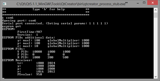
Помимо программы для полетного контроллера необходима еще одна программа: интерфейс настройки полетного контроллера. Чаще всего им является программа для PC, которая соединяется с полетным контроллером по USB и позволяет пользователю настраивать и проверять полетную программу, например: запускать калибровку радио, настраивать параметры стабилизации, проверять работу датчиков, задавать маршрут полета на карте, определять поведение мультикоптера при потере сигнала и многое другое. Мы свой интерфейс настройки будем писать на C++ и Qt в виде консольной утилиты. Вот она, если заглянуть в будущее:
Никто не застрахован от случайностей. Даже десятидюймовые пластиковые винты на маленьких моторах могут оставить кровавые синяки на коже, которые будут болеть еще неделю (проверено лично). Элементарно сделать себе новый макияж и прическу, если зацепить стик газа на пульте, пока несешь включенный квадрокоптер. Поэтому полетный контроллер должен обеспечивать хоть какую-то безопасность: механизм armed/disarmed. Состояние квадрокоптера «disarmed» означает, что моторы отключены и даже команда полного газа с пульта не имеет никакого эффекта, хотя питание подано. Состояние «armed» квадрокоптера означает, что команды с пульта выполняются полетным контроллером. В этом состоянии квадрокоптеры взлетают, летают и садятся. Квадрокоптер включается и должен сразу попасть в состояние disarmed на тот случай, если невнимальельный пилот включает его, когда стик газа на пульте находится не в нуле. Чтобы перевести коптер в состояние «armed» пилоту необхоимо сделать какой-то заранее оговоренный жест стиками пульта. Часто этим жестом является удержание левого стика в правом нижнем углу (газ = 0%, рыскание = 100%) втечении пары секунд. После этого полетный контроллер делает хотя бы минимальную самопроверку и при ее успешном прохождении «армится» (к полету готов!) Другим жестом (газ = 0%, рыскание = 0%) квадрокоптер «дизармится«. Еще одна хорошая мера безопасности — автодизарм, если газ был на нуле втечении 2-3 секунд.
О моторах, аккумуляторах, регуляторах, пропеллерах
Выбор комплектующих для мультикоптера — тема для целого цикла статей. Если вы собираетесь сделать свой первый квадрокоптер — сформулируйте, для чего он вам нужен, и воспользуйтесь советами бывалых или возьмите список комплектующих, который составил кто-то другой и успешно на нем летает.
И все же для общего понимания полезно знать основные моменты.
Аккумуляторы
Среди любителей и профессионалов многороторных систем наиболее распространены литий-полимерные аккумуляторы, как основные источники питания бортовой электроники и моторов. Их различают по емкости, напряжению и максимальной токоотдаче. Емкость, как обычно, измеряется в ампер-часах или миллиампер-часах. Напряжение измеряется в количестве «банок» аккумулятора. Одна «банка» — в среднем 3.7 вольт. Полностью заряженая «банка» — 4.2 вольта. Наиболее распространеты аккумуляторы с количеством банок от трех до шести. Максимальная токоотдача измеряется в амперах, а маркируется, например вот так: 25C. C — емкость аккумулятора, 25 — множитель. Если емкость равна 5 амперам, то такой аккумулятор может отдавать 25 * 5 = 125 ампер. Конечно же параметр токоотдачи лучше брать с запасом, но, в основном, чем он больше, тем дороже аккумулятор. Пример маркировки: 25C 3S 4500mah.
Каждая банка является отдельным аккумулятором. Все они спаяны последовательно. Для того чтобы равномерно заряжать все банки предусматривается баллансировочный разъем с доступом к каждой банке отдельно, и использутся специальные зарядные устройства.
Моторы, пропеллеры, регуляторы
Основной параметр бесколлекторного мотора — его kv. Это количество оборотов в минуту на каждый вольт поданного напряжения. Наиболее распространены моторы с kv от 300 до 1100. Kv ближе к 1000 обычно выбирают для малых квадрокоптеров (1-2 килограмма плюс 500 граммов полезной нагрузки) и ставят на них пластиковые пропеллеры до 12 дюймов в диаметре. На больших мультикоптерах (для поднятия хорошей и тяжелой фото-видео техники) или на долголетах (для рекордов по времени полета) обычно стоят моторы с низким kv (300-500) и огромными карбоновыми пропеллерами (15 — 20 дюймов в диаметре). Kv — не единственный важный параметр мотора: часто можно встретить целые таблицы зависимости мощности мотора и тяги от подаваемого напряжения и типа установленного пропеллера. Кроме того, каждый мотор рассчитан на свой диапазон напряжений (количество банок аккумулятора) и на свой максимальный ток. Если производитель пишет 3-4S, не стоит использовать его с 5S аккумуляторами. Это же касается и регуляторов.
Если мотор рассчитан на ток до 30А, то регулятор стоит рассчитывать на ток до 30 + 10А, чтобы не допускать перегревов. Некачественные или неподходящие регуляторы могут вызвать так называемые «срывы синхронизации» и остановку мотора в полете, и вы узнаете еще один мультироторный термин: «поймал планету.» Еще один важный момент — толщина и качество проводов. Неправильно рассчитанное сечение провода или плохой коннектор могут привести к пожару в воздухе.
Как видите, нюансов очень много. Я не перечислил даже половины, поэтому самому подобрать комплектующие для первого мультикоптера довольно трудно.
Математика стабилизации, ПИД-регуляторы (PID)
Если вы решили заняться мультикоптерами, то рано или поздно вам придется столкнуться с настройкой ПИД-регулятора, поскольку этот математический аппарат применяется почти во всех задачах стабилизации: стабилизация углов квадрокоптера в воздухе, полет и удержание позиции по GPS, удержание высоты по барометру, бесколлекторные механизмы стабилизации видеокамеры в полете (подвес камеры).
Вы приобретаете двухосевой подвес для камеры, ставите туда, например, GoPro, включаете и вместо стабилизации получаете конвульсии, вибрации и дергания, хотя все датчики откалиброваны и механические проблемы устранены. Причина — неверные параметры ПИД-регуляторов.
Вы собираете мультикоптер, калибруете датчики, регуляторы, радио, все проверяете, пытаетесь взлететь, а он такой унылый в воздухе, что его даже легким ветерком переворачивает. Или наоборот: он такой резкий, что внезапно срывается с места и крутит тройное сальто без разрешения. Причина все та же: параметры ПИД-регуляторов.
Для многих устройств использующих ПИД-регуляторы существуют инструкции по настройке, а то и несколько в добавок к многочисленным видеонструкциям от самих пользователей. Но чтобы легче ориентироваться в этом многообразии полезно понимать, как же внутри устроены эти регуляторы. Кроме того, мы же собираемся писать собственную систему стабилизации квадрокоптера! Предлагаю вместе со мной самим заново «изобрести» и «на пальцах» понять формулу ПИД-регулятора. Для тех, кому больше нравится сухой математический язык, я рекомендую Википедию, английскую статью, т.к. в русской пока не так подробно изложен материал.
Будем рассматривать квадрокоптер в двумерном пространстве, где у него есть только один угол — угол крена, и два мотора: левый и правый.

В полетный контроллер непрерывно поступают команды с земли: «крен 30 градусов», «крен -10 градусов», «крен 0 градусов (держать горизонт)»; его задача — как можно быстрее и точнее их выполнять с помощью моторов с учетом: ветра, неравномерного распределения веса квадрокоптера, неравномерного износа моторов, инерции квадрокоптера и т.п. Таким образом, полетный контроллер должен непрерывно решать задачу, какую скорость вращения подавать на каждый мотор с учетом текущего значения угла крена и требуемого. Непрерывно — это, конечно, громко сказано. Все зависит от вычислительных возможностей конкретного железа. На Adruino вполне можно одну итерацию цикла обработки и управления уместить в 10 миллисекунд. Это значит, что раз в 10 миллисекунд будут считываться показания углов квадрокоптера, и на их основе будут отправляться управляющие сигналы к моторам. Эти 10 миллисекунд называют периодом регулирования. Понятно, что чем он меньше, тем чаще и точнее происходит регулирование.
Уровень газа поступает из приемника в контроллер. Обозначим его . Напомню, что это среднее арифметическое между скоростями вращения всех моторов, выраженное в процентах от максимальной скорости вращения. Если и — скорости вращения левого и правого моторов, то:
где — реакция квадрокоптера (усилие), которое создает момент вращения за счет того, что левый мотор вращается на быстрее, чем газ, а правый — на столько же медленнее. может принимать и отрицательные значения, тогда правый мотор закрутится быстрее. Если мы научимся вычислять эту величину на каждой итерации цикла обработки, значит мы сможем управлять квадрокоптером. Понятно, что как минимум должно зависеть от текущего угла крена () и желаемого угла крена (), который поступает с пульта управления.
Представим ситуацию: поступает команда «держать горизонт» ( = 0), а квадрокоптер имеет крен влево:
— разность (ошибка) между и , которую контроллер стремится минимизировать.
Чем больше разность между желаемым углом крена и текущим, тем сильнее должна быть реакция, тем быстрее левый мотор должен закрутиться относительно правого. Если это записать с использованием наших обозначений:
Здесь P — коэффициент пропорциональности. Чем он больше, тем сильнее будет реакция, тем резче квадрокоптер будет реагировать на отклонение от требуемого угла крена. Эта интуитивно понятная и простая формула описывает работу пропорционального регулятора. Суть элементарна: чем сильнее квадрокоптер отклонился от требуемого положения, тем сильнее надо пытаться его вернуть. К сожалению, эту формулу придется усложнить. Главная причина — перерегулирование.
За несколько десятков миллисекунд (несколько итераций цикла обработки) под воздействием пропорционального регулятора квадрокоптер вернется в требуемое (в данном случае горизонтальное) положение. Все это время ошибка и усилие будут иметь один и тот же знак, хоть и становиться все меньше по модулю. Набрав какую-то скорость поворота (угловую скорость) квадрокоптер просто перевалится на другой бок, ведь никто его не остановит в требуемом положении. Все равно что пружина, которая всегда стремится вернуться в начальное положение, но если ее оттянуть и отпустить — будет колебаться, пока трение не возьмет верх. Конечно, на квадрокоптер тоже будет действовать трение, но практика показывает, что его не достаточно.
По этой причине в пропорциональный регулятор нужно добавить еще одно слагаемое, которое будет тормозить вращение квадрокоптера и препятствовать перерегулированию (переваливанию в противоположную сторону) — своего рода имитация трения в вязкой среде: чем быстрее поворачивается квадрокоптер, тем сильнее надо пытаться его остановить, конечно, в разумных пределах. Скорость вращения (скорость изменения ошибки ) обозначим как , тогда:
где D — настраиваемый коэффициент: чем он больше, тем сильнее останавливающее усилие. Из школьного курса физики всплывают смутные воспоминания, что скорость изменения любой величины — производная этой величины по времени:
.
И вот пропорциональный регулятор превращается в пропорционально-дифференциальный (пропорциональное слагаемое и дифференциальное):
.
Ошибку вычислить легко, ведь на каждой итерации мы знаем и ; P и D — настраиваемые перед запуском параметры. Для вычисления производной (скорости изменения ) необходимо хранить предыдущее значение, знать текущее значение и знать время, которое прошло между измерениями (период регулирования). И вот она — физика шестого класса школы (скорость = расстояние / время):
.
— период регулирования; — значение ошибки с предыдущей итерации цикла регуляции. Кстати, эта формула — простейший способ численного дифференцирования, и он нам здесь вполне подойдет.
Теперь у нас есть пропорционально-дифференциальный регулятор в плоском «бикоптере», но осталась еще одна проблема. Пусть левый край будет весить чуть больше правого, или, что то же самое, левый мотор работает чуть хуже правого. Квадрокоптер чуть наклонен влево и не поворачивается обратно: дифференциальное слагаемое равно нулю, а пропорциональное слагаемое хоть и принимает положительное значение, но его не хватает, чтобы вернуть квадрокоптер в горизонтальное положение, ведь левый край весит чуть больше правого. Как следствие — квадрокоптер будет все время тянуть влево.
Необходим механизм, который бы отслеживал такие отклонения и исправлял их. Характерной особенностью таких ошибок является то, что они прявляют себя со временем. На помощь приходит интегральное слагаемое. Оно хранит сумму всех ошибкок по всем итерациям цикла обработки. Как же это поможет? Если пропорционального слагаемого не достаточно, чтобы исправить маленькую ошибку, но она все равно есть — постепенно, со временем, набирает силы интегральное слагаемое, увеличивая реакцию и квадрокоптер принимает требуемый угол крена.
Тут есть нюанс. Предположим равна 1 градусу, цикл регулирования — 0.1с. Тогда за одну секунду сумма ошибок примет значение 10 градусов. А если цикл обработки — 0.01с, то сумма наберет аж 100 градусов. Чтобы за одно и тоже время интегральное слагаемое набирало одно и тоже значение при разных периодах регулирования, полученную сумму будем умножать на сам период регулирования. Легко посчитать, что в обоих случаях из примера получается сумма в 1 градус. Вот оно — интегральное слагаемое (пока без настраиваемого коэффициента):
.
Эта формула — не что иное, как численный интеграл по времени функции в интервале от нуля до текущего момента. Именно поэтому слагаемое называется интегральным:
,
где T — текущий момент времени.
Пришло время записать окончательную формулу пропорционально-интергрально-дифференциального регулятора:

,
где — один из настраиваемых параметров, которых теперь трое: . Эта формула удобна в применении из программного кода, а вот формула, которая приводится в учебниках:
.
Существует несколько ее вариаций, например, можно ограничить модуль интегрального слагаемого, чтобы он не превысил определенный допустимый порог (мы так и будем делать).
Практика
Ну а теперь пришло время для практики подбора коэффициентов. Читателям предлагается JavaScript-страничка с виртуальным квадрокоптером, который он уже видел на картинках:
подбор параметров PID-регулятора для квадрокоптера
(JSFiddle). При первом запуске сразу видно перерегулирование — колебания вокруг требуемого положения. Когда колебания останавливаются, можно наблюдать эффект, что пропорциональный коэффициент не справляется с ошибкой из-за «несимметричного» квадрокоптера (задается галочкой «Asymmetry»). Для настройки доступны параметры P, I, D. Теперь вы знаете что с ними делать. «Скролом» под квадрокоптером можно управлять требуемым значением крена. «Interval (ms):» — интервал регулирования. Уменьшать его — «читерство», но посмотреть как он влияет на качество стабилизации — очень полезно.
Для любителей «чистой» математики можно предложить
настроить абстрактный ПИД-регулятор
Введенные параметры автоматически не применяются: нужно жмакать «Apply». Пара небольших советов: если вам кажется, что квадрокоптер слишком медленно реагирует на управление — можно увеличить P, но слишком большое значение P может привести к перерегулированию. С перерегулированием поможет справиться параметр D, но слишком большие значения приведут к частым колебаниям, или опять к перерегулированию. Параметр I, обычно, в 10 — 100 раз меньше, чем параметр P т.к. его сила в накоплении во времени, а не в быстром реагировании.
Ручная настройка ПИД-параметров требует практики. Существуют аналитические методы их вычисления, но они требуют хорошей подготовки и точного знания многих параметров конкретной настраиваемой системы. Как среднее между ручным подбором и аналитическим вычислением есть широкий ряд эмпирических методов, предложенных различными исследователями.
В нашем 2D квадрокоптере меняется только один угол — угол крена. В настроящем 3D квадрокоптере потребуется три независимых ПИД-регулятора для каждого из углов, а управление конкретным мотором будет представлять сумму усилий по всем регуляторам.
Заключение первой части
В этой статье мы познакомились с базовыми понятиями: квадрокоптер и принцип полета, тангаж, крен, рыскание, газ, газ висения, режим полета stabilize, полетный контроллер, гироскоп, акселерометр, регулятор скорости, ШИМ, калибровка регуляторов, калибровка радио, бортовой приемник, интерфейс настройки полетного контроллера, состояния armed/disarmed, автодизарм.
После этого мы заново изобрели формулу ПИД-регулятора немного каснувшись численного дифференцирования и интегрирования, и на своей шкуре испытали, как настраивать параметры P, I, D на
виртуальном квадрокоптере
.
Теперь, если вы владеете световым мечем-программированием, вы можете приступать к своей программе стабилизации квадрокоптера, или, еще лучше, присоединиться со свежими идеями к существующими open source проектам. Ну а я
через неделю-другую
, когда появятся силы и время, чтобы соответствовать качеству, продолжу рассказ, как это все программировалось, тестировалось, падало, резало мне пальцы и вовсе улетало в неизвестном направлении. Если вам очень захотелось продолжения — можете напнуть меня здесь или, например, Вконтакте: это немного придает стимула.
В заключении этой части я просто обязан упомянуть человека, который помогал мне в выборе комплектующих и настройке самого сложного (первого!) квадрокоптера на прошивке MegapirateNG и терпеливо отвечал на сотни вопросов по этим самым базовым понятиям: SovGVD, спасибо тебе!
В награду тем, кто смог промотать всю эту простыню, выкладываю обещанное маленькое видео, как наш квадрокоптер с нашими «изобретенными» ПИД-регуляторами, на нашей программе для Arduino Mega 2560 летает:
Конечно, ему не хватает GPS, как в коммерческих и массовых продуктах, немного не хватает устойчивости, но зато — НАШ, и мы знаем его вдоль и поперек до последнего множителя при интегральном коэффициенте! И это действительно круто, что сегодня нам доступны такие технологии.
Разве не в прекрасное время мы живем?!
Только зарегистрированные пользователи могут участвовать в опросе. Войдите, пожалуйста.
В какое время мы живем?
Проголосовали 1811 пользователей. Воздержались 253 пользователя.
Кому нужны навороченные готовые дроны, когда можно создать свой собственный шедевр? Этот гайд — ваш универсальный помощник в создании крутого дрона на базе Arduino. И поверьте, он будет круче (и, скорее всего, дешевле), чем любой дрон из магазина.
Мы будем использовать плату Arduino в качестве мозга нашего квадрокоптера, программируя её для управления моторами, чтобы ваш дрон взлетел в небо. Представьте, что это большой летающий и настраиваемый робот, который вы сделали сами — как это круто!?
Этот гайд идеально подходит для тех, кто хочет:
- Испытать острые ощущения от создания дрона с нуля
- Узнать основы программирования Arduino и управления полётом
- Выпустить своего внутреннего безумного учёного (ну или просто любителя дронов)
Так что, если вы готовы отказаться от магазинных решений и создать что-то по-настоящему уникальное, надевайте свои воображаемые очки и приступим!
Необходимые материалы
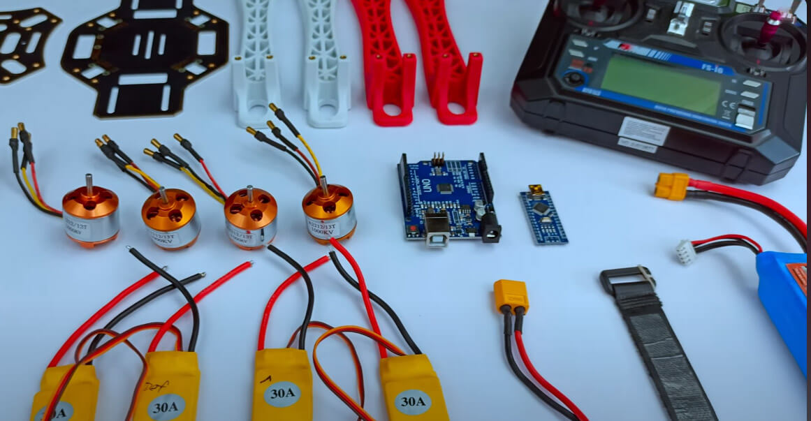
Для создания этого проекта вам понадобятся:
- Каркас дрона F450
- Бесколлекторные моторы 1000 KV x4
- Регуляторы скорости (ESC) 30A x4
- Пропеллеры x4
- Модуль MPU 6050
- Литий-полимерный аккумулятор 2200 мАч
- Разъёмы XT60 (папа, мама, можно найти в любом магазине электроники)
- Передатчик и приёмник Flysky FS-I6
Шаг 1: Пайка разъёма аккумулятора и ESC
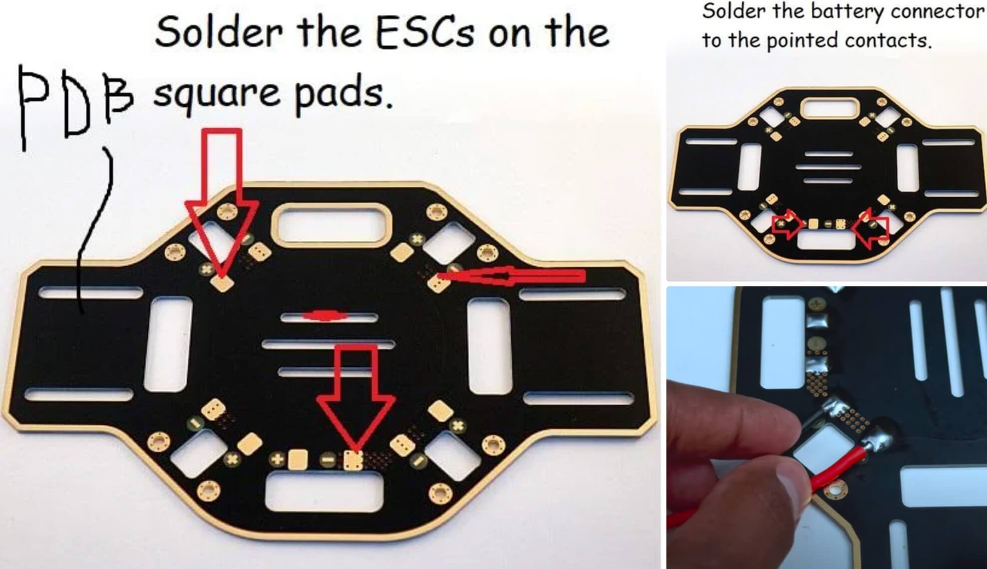
PDB (Power Distribution Board) — это нижняя пластина каркаса с квадратными площадками вокруг. Припаяйте ESC к PDB, как показано на изображении. Проверьте полярность!
Также есть дополнительные площадки для соединения аккумулятора. Припаяйте женский разъём XT60 к этим площадкам, убедившись, что красный провод идет к положительному контакту, а чёрный — к отрицательному.
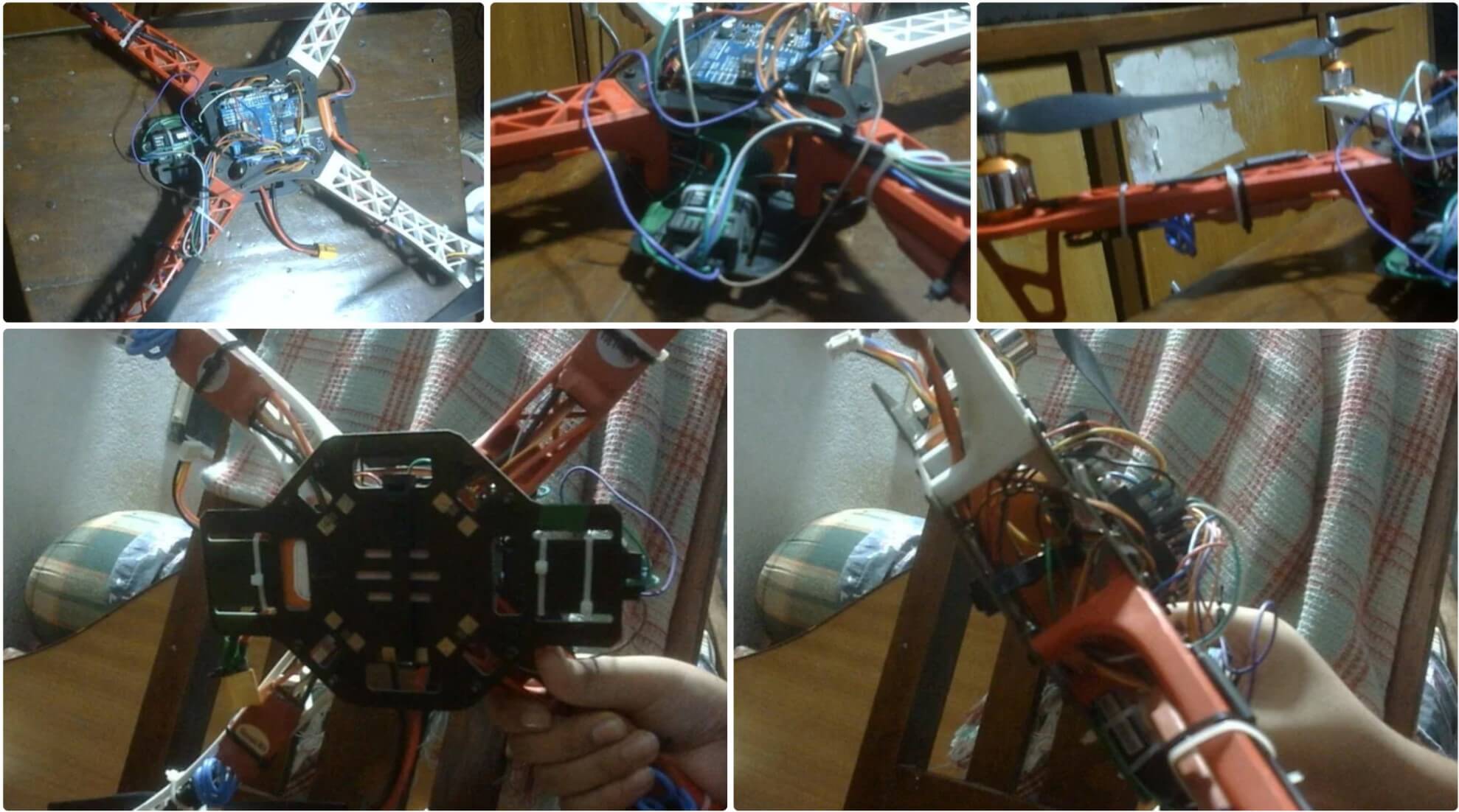
Шаг 2: Сборка каркаса
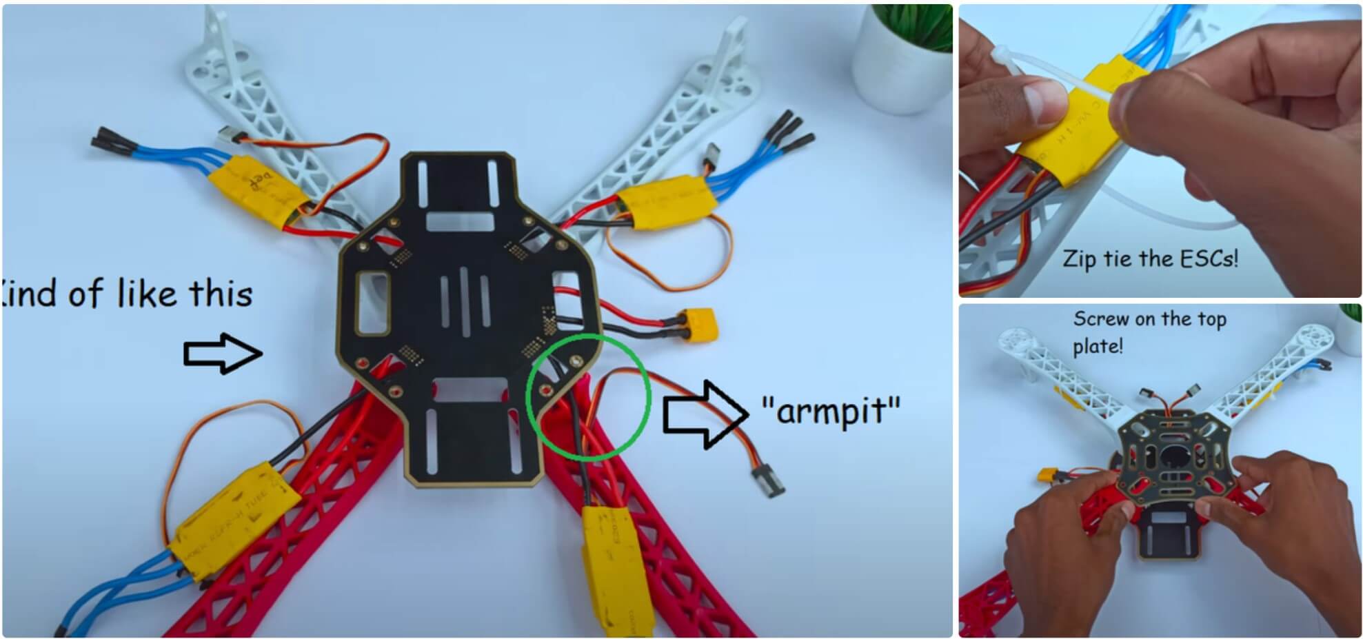
Теперь пришло время собрать каркас. Прикрутите «руки» к нижней пластине и проведите ESC через «подмышки» (маленькие арки). Затем закрепите ESC на нижней стороне каркаса с помощью стяжек. После обрезки лишнего пластика стяжек прикрутите верхнюю пластину. Это довольно просто, хотя там 16 винтов! Потеря хотя бы одного сделает верхнюю пластину очень нестабильной, а это плохо, так как на неё будем монтировать электронику. Так что, если потеряли винт, сразу найдите замену!
Шаг 3: Построение схемы
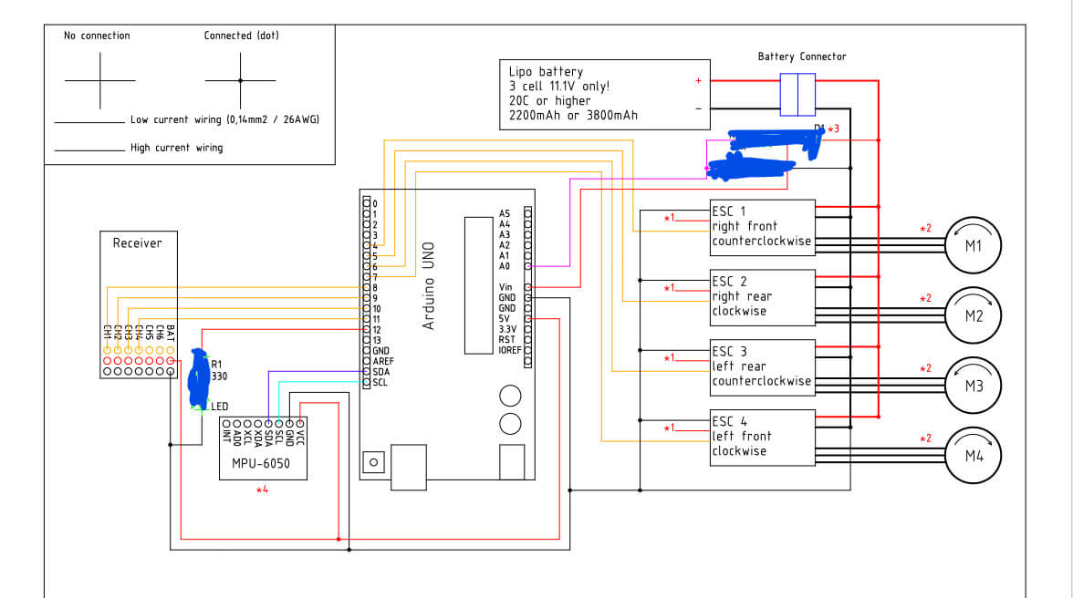
Вот схема подключения. Не беспокойтесь о затемнённых областях, это не важно. Этот дизайн был утомительным, и я даже случайно уничтожил старый Arduino Uno, работая над схемой питания.
Подключите все компоненты и постарайтесь аккуратно уложить провода, используя множество стяжек и изоленты. Я работаю над верхним корпусом и добавлю STL-файлы в следующем обновлении.
Использовал массивные стяжки, чтобы надежно прикрепить аккумулятор к нижней палубе каркаса дрона.
Шаг 4: Программирование дрона. Часть 1
Чтобы начать откройте Arduino IDE.
Совет: всегда запускайте Arduino IDE с правами администратора. Это решит множество проблем с загрузкой и доступом к Arduino через Serial Monitor.
Сначала откройте скетч ClearEEPROM и загрузите его. Если в Arduino загружены предыдущие скетчи, загрузите пустой скетч, а затем ClearEEPROM.
ClearEEPROM
#include

void setup(){
  for (int i = 0 ; i < EEPROM.length() ; i++){
    EEPROM.write(i, 0);
  }

}

void loop(){
  //Do nothing here...
}
DroneSetup
#include //Include the Wire.h library so we can communicate with the gyro
#include //Include the EEPROM.h library so we can store information onto the EEPROM
//Declaring Global Variables
byte last_channel_1, last_channel_2, last_channel_3, last_channel_4;
byte lowByte, highByte, type, gyro_address, error, clockspeed_ok;
byte channel_1_assign, channel_2_assign, channel_3_assign, channel_4_assign;
byte roll_axis, pitch_axis, yaw_axis;
byte receiver_check_byte, gyro_check_byte;
volatile int receiver_input_channel_1, receiver_input_channel_2, receiver_input_channel_3, receiver_input_channel_4;
int center_channel_1, center_channel_2, center_channel_3, center_channel_4;
int high_channel_1, high_channel_2, high_channel_3, high_channel_4;
int low_channel_1, low_channel_2, low_channel_3, low_channel_4;
int address, cal_int;
unsigned long timer, timer_1, timer_2, timer_3, timer_4, current_time;
float gyro_pitch, gyro_roll, gyro_yaw;
float gyro_roll_cal, gyro_pitch_cal, gyro_yaw_cal;
//Setup routine
void setup(){
pinMode(12, OUTPUT);
//Arduino (Atmega) pins default to inputs, so they don't need to be explicitly declared as inputs
PCICR |= (1 << PCIE0); // set PCIE0 to enable PCMSK0 scan
PCMSK0 |= (1 << PCINT0); // set PCINT0 (digital input 8) to trigger an interrupt on state change
PCMSK0 |= (1 << PCINT1); // set PCINT1 (digital input 9)to trigger an interrupt on state change
PCMSK0 |= (1 << PCINT2); // set PCINT2 (digital input 10)to trigger an interrupt on state change
PCMSK0 |= (1 << PCINT3); // set PCINT3 (digital input 11)to trigger an interrupt on state change Wire.begin(); //Start the I2C as master Serial.begin(57600); //Start the serial connetion @ 57600bps delay(250); //Give the gyro time to start } //Main program void loop(){ //Show the YMFC-3D V2 intro intro(); Serial.println(F("")); Serial.println(F("===================================================")); Serial.println(F("System check")); Serial.println(F("===================================================")); delay(1000); Serial.println(F("Checking I2C clock speed.")); delay(1000); TWBR = 12; //Set the I2C clock speed to 400kHz. #if F_CPU == 16000000L //If the clock speed is 16MHz include the next code line when compiling clockspeed_ok = 1; //Set clockspeed_ok to 1 #endif //End of if statement if(TWBR == 12 && clockspeed_ok){ Serial.println(F("I2C clock speed is correctly set to 400kHz.")); } else{ Serial.println(F("I2C clock speed is not set to 400kHz. (ERROR 8)")); error = 1; } if(error == 0){ Serial.println(F("")); Serial.println(F("===================================================")); Serial.println(F("Transmitter setup")); Serial.println(F("===================================================")); delay(1000); Serial.print(F("Checking for valid receiver signals.")); //Wait 10 seconds until all receiver inputs are valid wait_for_receiver(); Serial.println(F("")); } //Quit the program in case of an error if(error == 0){ delay(2000); Serial.println(F("Place all sticks and subtrims in the center position within 10 seconds.")); for(int i = 9;i > 0;i--){
delay(1000);
Serial.print(i);
Serial.print(" ");
}
Serial.println(" ");
//Store the central stick positions
center_channel_1 = receiver_input_channel_1;
center_channel_2 = receiver_input_channel_2;
center_channel_3 = receiver_input_channel_3;
center_channel_4 = receiver_input_channel_4;
Serial.println(F(""));
Serial.println(F("Center positions stored."));
Serial.print(F("Digital input 08 = "));
Serial.println(receiver_input_channel_1);
Serial.print(F("Digital input 09 = "));
Serial.println(receiver_input_channel_2);
Serial.print(F("Digital input 10 = "));
Serial.println(receiver_input_channel_3);
Serial.print(F("Digital input 11 = "));
Serial.println(receiver_input_channel_4);
Serial.println(F(""));
Serial.println(F(""));
}
if(error == 0){
Serial.println(F("Move the throttle stick to full throttle and back to center"));
//Check for throttle movement
check_receiver_inputs(1);
Serial.print(F("Throttle is connected to digital input "));
Serial.println((channel_3_assign & 0b00000111) + 7);
if(channel_3_assign & 0b10000000)Serial.println(F("Channel inverted = yes"));
else Serial.println(F("Channel inverted = no"));
wait_sticks_zero();
Serial.println(F(""));
Serial.println(F(""));
Serial.println(F("Move the roll stick to simulate left wing up and back to center"));
//Check for throttle movement
check_receiver_inputs(2);
Serial.print(F("Roll is connected to digital input "));
Serial.println((channel_1_assign & 0b00000111) + 7);
if(channel_1_assign & 0b10000000)Serial.println(F("Channel inverted = yes"));
else Serial.println(F("Channel inverted = no"));
wait_sticks_zero();
}
if(error == 0){
Serial.println(F(""));
Serial.println(F(""));
Serial.println(F("Move the pitch stick to simulate nose up and back to center"));
//Check for throttle movement
check_receiver_inputs(3);
Serial.print(F("Pitch is connected to digital input "));
Serial.println((channel_2_assign & 0b00000111) + 7);
if(channel_2_assign & 0b10000000)Serial.println(F("Channel inverted = yes"));
else Serial.println(F("Channel inverted = no"));
wait_sticks_zero();
}
if(error == 0){
Serial.println(F(""));
Serial.println(F(""));
Serial.println(F("Move the yaw stick to simulate nose right and back to center"));
//Check for throttle movement
check_receiver_inputs(4);
Serial.print(F("Yaw is connected to digital input "));
Serial.println((channel_4_assign & 0b00000111) + 7);
if(channel_4_assign & 0b10000000)Serial.println(F("Channel inverted = yes"));
else Serial.println(F("Channel inverted = no"));
wait_sticks_zero();
}
if(error == 0){
Serial.println(F(""));
Serial.println(F(""));
Serial.println(F("Gently move all the sticks simultaneously to their extends"));
Serial.println(F("When ready put the sticks back in their center positions"));
//Register the min and max values of the receiver channels
register_min_max();
Serial.println(F(""));
Serial.println(F(""));
Serial.println(F("High, low and center values found during setup"));
Serial.print(F("Digital input 08 values:"));
Serial.print(low_channel_1);
Serial.print(F(" - "));
Serial.print(center_channel_1);
Serial.print(F(" - "));
Serial.println(high_channel_1);
Serial.print(F("Digital input 09 values:"));
Serial.print(low_channel_2);
Serial.print(F(" - "));
Serial.print(center_channel_2);
Serial.print(F(" - "));
Serial.println(high_channel_2);
Serial.print(F("Digital input 10 values:"));
Serial.print(low_channel_3);
Serial.print(F(" - "));
Serial.print(center_channel_3);
Serial.print(F(" - "));
Serial.println(high_channel_3);
Serial.print(F("Digital input 11 values:"));
Serial.print(low_channel_4);
Serial.print(F(" - "));
Serial.print(center_channel_4);
Serial.print(F(" - "));
Serial.println(high_channel_4);
Serial.println(F("Move stick 'nose up' and back to center to continue"));
check_to_continue();
}
if(error == 0){
//What gyro is connected
Serial.println(F(""));
Serial.println(F("==================================================="));
Serial.println(F("Gyro search"));
Serial.println(F("==================================================="));
delay(2000);
Serial.println(F("Searching for MPU-6050 on address 0x68/104"));
delay(1000);
if(search_gyro(0x68, 0x75) == 0x68){
Serial.println(F("MPU-6050 found on address 0x68"));
type = 1;
gyro_address = 0x68;
}
if(type == 0){
Serial.println(F("Searching for MPU-6050 on address 0x69/105"));
delay(1000);
if(search_gyro(0x69, 0x75) == 0x68){
Serial.println(F("MPU-6050 found on address 0x69"));
type = 1;
gyro_address = 0x69;
}
}
if(type == 0){
Serial.println(F("Searching for L3G4200D on address 0x68/104"));
delay(1000);
if(search_gyro(0x68, 0x0F) == 0xD3){
Serial.println(F("L3G4200D found on address 0x68"));
type = 2;
gyro_address = 0x68;
}
}
if(type == 0){
Serial.println(F("Searching for L3G4200D on address 0x69/105"));
delay(1000);
if(search_gyro(0x69, 0x0F) == 0xD3){
Serial.println(F("L3G4200D found on address 0x69"));
type = 2;
gyro_address = 0x69;
}
}
if(type == 0){
Serial.println(F("Searching for L3GD20H on address 0x6A/106"));
delay(1000);
if(search_gyro(0x6A, 0x0F) == 0xD7){
Serial.println(F("L3GD20H found on address 0x6A"));
type = 3;
gyro_address = 0x6A;
}
}
if(type == 0){
Serial.println(F("Searching for L3GD20H on address 0x6B/107"));
delay(1000);
if(search_gyro(0x6B, 0x0F) == 0xD7){
Serial.println(F("L3GD20H found on address 0x6B"));
type = 3;
gyro_address = 0x6B;
}
}
if(type == 0){
Serial.println(F("No gyro device found!!! (ERROR 3)"));
error = 1;
}
else{
delay(3000);
Serial.println(F(""));
Serial.println(F("==================================================="));
Serial.println(F("Gyro register settings"));
Serial.println(F("==================================================="));
start_gyro(); //Setup the gyro for further use
}
}
//If the gyro is found we can setup the correct gyro axes.
if(error == 0){
delay(3000);
Serial.println(F(""));
Serial.println(F("==================================================="));
Serial.println(F("Gyro calibration"));
Serial.println(F("==================================================="));
Serial.println(F("Don't move the quadcopter!! Calibration starts in 3 seconds"));
delay(3000);
Serial.println(F("Calibrating the gyro, this will take +/- 8 seconds"));
Serial.print(F("Please wait"));
//Let's take multiple gyro data samples so we can determine the average gyro offset (calibration).
for (cal_int = 0; cal_int < 2000 ; cal_int ++){ //Take 2000 readings for calibration. if(cal_int % 100 == 0)Serial.print(F(".")); //Print dot to indicate calibration. gyro_signalen(); //Read the gyro output. gyro_roll_cal += gyro_roll; //Ad roll value to gyro_roll_cal. gyro_pitch_cal += gyro_pitch; //Ad pitch value to gyro_pitch_cal. gyro_yaw_cal += gyro_yaw; //Ad yaw value to gyro_yaw_cal. delay(4); //Wait 3 milliseconds before the next loop. } //Now that we have 2000 measures, we need to devide by 2000 to get the average gyro offset. gyro_roll_cal /= 2000; //Divide the roll total by 2000. gyro_pitch_cal /= 2000; //Divide the pitch total by 2000. gyro_yaw_cal /= 2000; //Divide the yaw total by 2000. //Show the calibration results Serial.println(F("")); Serial.print(F("Axis 1 offset=")); Serial.println(gyro_roll_cal); Serial.print(F("Axis 2 offset=")); Serial.println(gyro_pitch_cal); Serial.print(F("Axis 3 offset=")); Serial.println(gyro_yaw_cal); Serial.println(F("")); Serial.println(F("===================================================")); Serial.println(F("Gyro axes configuration")); Serial.println(F("===================================================")); //Detect the left wing up movement Serial.println(F("Lift the left side of the quadcopter to a 45 degree angle within 10 seconds")); //Check axis movement check_gyro_axes(1); if(error == 0){ Serial.println(F("OK!")); Serial.print(F("Angle detection = ")); Serial.println(roll_axis & 0b00000011); if(roll_axis & 0b10000000)Serial.println(F("Axis inverted = yes")); else Serial.println(F("Axis inverted = no")); Serial.println(F("Put the quadcopter back in its original position")); Serial.println(F("Move stick 'nose up' and back to center to continue")); check_to_continue(); //Detect the nose up movement Serial.println(F("")); Serial.println(F("")); Serial.println(F("Lift the nose of the quadcopter to a 45 degree angle within 10 seconds")); //Check axis movement check_gyro_axes(2); } if(error == 0){ Serial.println(F("OK!")); Serial.print(F("Angle detection = ")); Serial.println(pitch_axis & 0b00000011); if(pitch_axis & 0b10000000)Serial.println(F("Axis inverted = yes")); else Serial.println(F("Axis inverted = no")); Serial.println(F("Put the quadcopter back in its original position")); Serial.println(F("Move stick 'nose up' and back to center to continue")); check_to_continue(); //Detect the nose right movement Serial.println(F("")); Serial.println(F("")); Serial.println(F("Rotate the nose of the quadcopter 45 degree to the right within 10 seconds")); //Check axis movement check_gyro_axes(3); } if(error == 0){ Serial.println(F("OK!")); Serial.print(F("Angle detection = ")); Serial.println(yaw_axis & 0b00000011); if(yaw_axis & 0b10000000)Serial.println(F("Axis inverted = yes")); else Serial.println(F("Axis inverted = no")); Serial.println(F("Put the quadcopter back in its original position")); Serial.println(F("Move stick 'nose up' and back to center to continue")); check_to_continue(); } } if(error == 0){ Serial.println(F("")); Serial.println(F("===================================================")); Serial.println(F("LED test")); Serial.println(F("===================================================")); digitalWrite(12, HIGH); Serial.println(F("The LED should now be lit")); Serial.println(F("Move stick 'nose up' and back to center to continue")); check_to_continue(); digitalWrite(12, LOW); } Serial.println(F("")); if(error == 0){ Serial.println(F("===================================================")); Serial.println(F("Final setup check")); Serial.println(F("===================================================")); delay(1000); if(receiver_check_byte == 0b00001111){ Serial.println(F("Receiver channels ok")); } else{ Serial.println(F("Receiver channel verification failed!!! (ERROR 6)")); error = 1; } delay(1000); if(gyro_check_byte == 0b00000111){ Serial.println(F("Gyro axes ok")); } else{ Serial.println(F("Gyro exes verification failed!!! (ERROR 7)")); error = 1; } } if(error == 0){ //If all is good, store the information in the EEPROM Serial.println(F("")); Serial.println(F("===================================================")); Serial.println(F("Storing EEPROM information")); Serial.println(F("===================================================")); Serial.println(F("Writing EEPROM")); delay(1000); Serial.println(F("Done!")); EEPROM.write(0, center_channel_1 & 0b11111111); EEPROM.write(1, center_channel_1 >> 8);
EEPROM.write(2, center_channel_2 & 0b11111111);
EEPROM.write(3, center_channel_2 >> 8);
EEPROM.write(4, center_channel_3 & 0b11111111);
EEPROM.write(5, center_channel_3 >> 8);
EEPROM.write(6, center_channel_4 & 0b11111111);
EEPROM.write(7, center_channel_4 >> 8);
EEPROM.write(8, high_channel_1 & 0b11111111);
EEPROM.write(9, high_channel_1 >> 8);
EEPROM.write(10, high_channel_2 & 0b11111111);
EEPROM.write(11, high_channel_2 >> 8);
EEPROM.write(12, high_channel_3 & 0b11111111);
EEPROM.write(13, high_channel_3 >> 8);
EEPROM.write(14, high_channel_4 & 0b11111111);
EEPROM.write(15, high_channel_4 >> 8);
EEPROM.write(16, low_channel_1 & 0b11111111);
EEPROM.write(17, low_channel_1 >> 8);
EEPROM.write(18, low_channel_2 & 0b11111111);
EEPROM.write(19, low_channel_2 >> 8);
EEPROM.write(20, low_channel_3 & 0b11111111);
EEPROM.write(21, low_channel_3 >> 8);
EEPROM.write(22, low_channel_4 & 0b11111111);
EEPROM.write(23, low_channel_4 >> 8);
EEPROM.write(24, channel_1_assign);
EEPROM.write(25, channel_2_assign);
EEPROM.write(26, channel_3_assign);
EEPROM.write(27, channel_4_assign);
EEPROM.write(28, roll_axis);
EEPROM.write(29, pitch_axis);
EEPROM.write(30, yaw_axis);
EEPROM.write(31, type);
EEPROM.write(32, gyro_address);
//Write the EEPROM signature
EEPROM.write(33, 'J');
EEPROM.write(34, 'M');
EEPROM.write(35, 'B');
//To make sure evrything is ok, verify the EEPROM data.
Serial.println(F("Verify EEPROM data"));
delay(1000);
if(center_channel_1 != ((EEPROM.read(1) << 8) | EEPROM.read(0)))error = 1;
if(center_channel_2 != ((EEPROM.read(3) << 8) | EEPROM.read(2)))error = 1;
if(center_channel_3 != ((EEPROM.read(5) << 8) | EEPROM.read(4)))error = 1;
if(center_channel_4 != ((EEPROM.read(7) << 8) | EEPROM.read(6)))error = 1;
if(high_channel_1 != ((EEPROM.read(9) << 8) | EEPROM.read(8)))error = 1;
if(high_channel_2 != ((EEPROM.read(11) << 8) | EEPROM.read(10)))error = 1;
if(high_channel_3 != ((EEPROM.read(13) << 8) | EEPROM.read(12)))error = 1;
if(high_channel_4 != ((EEPROM.read(15) << 8) | EEPROM.read(14)))error = 1;
if(low_channel_1 != ((EEPROM.read(17) << 8) | EEPROM.read(16)))error = 1;
if(low_channel_2 != ((EEPROM.read(19) << 8) | EEPROM.read(18)))error = 1;
if(low_channel_3 != ((EEPROM.read(21) << 8) | EEPROM.read(20)))error = 1;
if(low_channel_4 != ((EEPROM.read(23) << 8) | EEPROM.read(22)))error = 1;
if(channel_1_assign != EEPROM.read(24))error = 1;
if(channel_2_assign != EEPROM.read(25))error = 1;
if(channel_3_assign != EEPROM.read(26))error = 1;
if(channel_4_assign != EEPROM.read(27))error = 1;
if(roll_axis != EEPROM.read(28))error = 1;
if(pitch_axis != EEPROM.read(29))error = 1;
if(yaw_axis != EEPROM.read(30))error = 1;
if(type != EEPROM.read(31))error = 1;
if(gyro_address != EEPROM.read(32))error = 1;
if('J' != EEPROM.read(33))error = 1;
if('M' != EEPROM.read(34))error = 1;
if('B' != EEPROM.read(35))error = 1;
if(error == 1)Serial.println(F("EEPROM verification failed!!! (ERROR 5)"));
else Serial.println(F("Verification done"));
}
if(error == 0){
Serial.println(F("Setup is finished."));
Serial.println(F("You can now calibrate the esc's and upload the YMFC-AL code."));
}
else{
Serial.println(F("The setup is aborted due to an error."));
Serial.println(F("Check the Q and A page of the YMFC-AL project on:"));
Serial.println(F("www.brokking.net for more information about this error."));
}
while(1);
}
//Search for the gyro and check the Who_am_I register
byte search_gyro(int gyro_address, int who_am_i){
Wire.beginTransmission(gyro_address);
Wire.write(who_am_i);
Wire.endTransmission();
Wire.requestFrom(gyro_address, 1);
timer = millis() + 100;
while(Wire.available() < 1 && timer > millis());
lowByte = Wire.read();
address = gyro_address;
return lowByte;
}
void start_gyro(){
//Setup the L3G4200D or L3GD20H
if(type == 2 || type == 3){
Wire.beginTransmission(address); //Start communication with the gyro with the address found during search
Wire.write(0x20); //We want to write to register 1 (20 hex)
Wire.write(0x0F); //Set the register bits as 00001111 (Turn on the gyro and enable all axis)
Wire.endTransmission(); //End the transmission with the gyro
Wire.beginTransmission(address); //Start communication with the gyro (adress 1101001)
Wire.write(0x20); //Start reading @ register 28h and auto increment with every read
Wire.endTransmission(); //End the transmission
Wire.requestFrom(address, 1); //Request 6 bytes from the gyro
while(Wire.available() < 1); //Wait until the 1 byte is received
Serial.print(F("Register 0x20 is set to:"));
Serial.println(Wire.read(),BIN);
Wire.beginTransmission(address); //Start communication with the gyro with the address found during search
Wire.write(0x23); //We want to write to register 4 (23 hex)
Wire.write(0x90); //Set the register bits as 10010000 (Block Data Update active & 500dps full scale)
Wire.endTransmission(); //End the transmission with the gyro
Wire.beginTransmission(address); //Start communication with the gyro (adress 1101001)
Wire.write(0x23); //Start reading @ register 28h and auto increment with every read
Wire.endTransmission(); //End the transmission
Wire.requestFrom(address, 1); //Request 6 bytes from the gyro
while(Wire.available() < 1); //Wait until the 1 byte is received
Serial.print(F("Register 0x23 is set to:"));
Serial.println(Wire.read(),BIN);
}
//Setup the MPU-6050
if(type == 1){
Wire.beginTransmission(address); //Start communication with the gyro
Wire.write(0x6B); //PWR_MGMT_1 register
Wire.write(0x00); //Set to zero to turn on the gyro
Wire.endTransmission(); //End the transmission
Wire.beginTransmission(address); //Start communication with the gyro
Wire.write(0x6B); //Start reading @ register 28h and auto increment with every read
Wire.endTransmission(); //End the transmission
Wire.requestFrom(address, 1); //Request 1 bytes from the gyro
while(Wire.available() < 1); //Wait until the 1 byte is received
Serial.print(F("Register 0x6B is set to:"));
Serial.println(Wire.read(),BIN);
Wire.beginTransmission(address); //Start communication with the gyro
Wire.write(0x1B); //GYRO_CONFIG register
Wire.write(0x08); //Set the register bits as 00001000 (500dps full scale)
Wire.endTransmission(); //End the transmission
Wire.beginTransmission(address); //Start communication with the gyro (adress 1101001)
Wire.write(0x1B); //Start reading @ register 28h and auto increment with every read
Wire.endTransmission(); //End the transmission
Wire.requestFrom(address, 1); //Request 1 bytes from the gyro
while(Wire.available() < 1); //Wait until the 1 byte is received
Serial.print(F("Register 0x1B is set to:"));
Serial.println(Wire.read(),BIN);
}
}
void gyro_signalen(){
if(type == 2 || type == 3){
Wire.beginTransmission(address); //Start communication with the gyro
Wire.write(168); //Start reading @ register 28h and auto increment with every read
Wire.endTransmission(); //End the transmission
Wire.requestFrom(address, 6); //Request 6 bytes from the gyro
while(Wire.available() < 6); //Wait until the 6 bytes are received
lowByte = Wire.read(); //First received byte is the low part of the angular data
highByte = Wire.read(); //Second received byte is the high part of the angular data
gyro_roll = ((highByte<<8)|lowByte); //Multiply highByte by 256 (shift left by 8) and ad lowByte
if(cal_int == 2000)gyro_roll -= gyro_roll_cal; //Only compensate after the calibration
lowByte = Wire.read(); //First received byte is the low part of the angular data
highByte = Wire.read(); //Second received byte is the high part of the angular data
gyro_pitch = ((highByte<<8)|lowByte); //Multiply highByte by 256 (shift left by 8) and ad lowByte
if(cal_int == 2000)gyro_pitch -= gyro_pitch_cal; //Only compensate after the calibration
lowByte = Wire.read(); //First received byte is the low part of the angular data
highByte = Wire.read(); //Second received byte is the high part of the angular data
gyro_yaw = ((highByte<<8)|lowByte); //Multiply highByte by 256 (shift left by 8) and ad lowByte
if(cal_int == 2000)gyro_yaw -= gyro_yaw_cal; //Only compensate after the calibration
}
if(type == 1){
Wire.beginTransmission(address); //Start communication with the gyro
Wire.write(0x43); //Start reading @ register 43h and auto increment with every read
Wire.endTransmission(); //End the transmission
Wire.requestFrom(address,6); //Request 6 bytes from the gyro
while(Wire.available() < 6); //Wait until the 6 bytes are received
gyro_roll=Wire.read()<<8|Wire.read(); //Read high and low part of the angular data
if(cal_int == 2000)gyro_roll -= gyro_roll_cal; //Only compensate after the calibration
gyro_pitch=Wire.read()<<8|Wire.read(); //Read high and low part of the angular data
if(cal_int == 2000)gyro_pitch -= gyro_pitch_cal; //Only compensate after the calibration
gyro_yaw=Wire.read()<<8|Wire.read(); //Read high and low part of the angular data if(cal_int == 2000)gyro_yaw -= gyro_yaw_cal; //Only compensate after the calibration } } //Check if a receiver input value is changing within 30 seconds void check_receiver_inputs(byte movement){ byte trigger = 0; int pulse_length; timer = millis() + 30000; while(timer > millis() && trigger == 0){
delay(250);
if(receiver_input_channel_1 > 1750 || receiver_input_channel_1 < 1250){ trigger = 1; receiver_check_byte |= 0b00000001; pulse_length = receiver_input_channel_1; } if(receiver_input_channel_2 > 1750 || receiver_input_channel_2 < 1250){ trigger = 2; receiver_check_byte |= 0b00000010; pulse_length = receiver_input_channel_2; } if(receiver_input_channel_3 > 1750 || receiver_input_channel_3 < 1250){ trigger = 3; receiver_check_byte |= 0b00000100; pulse_length = receiver_input_channel_3; } if(receiver_input_channel_4 > 1750 || receiver_input_channel_4 < 1250){
trigger = 4;
receiver_check_byte |= 0b00001000;
pulse_length = receiver_input_channel_4;
}
}
if(trigger == 0){
error = 1;
Serial.println(F("No stick movement detected in the last 30 seconds!!! (ERROR 2)"));
}
//Assign the stick to the function.
else{
if(movement == 1){
channel_3_assign = trigger;
if(pulse_length < 1250)channel_3_assign += 0b10000000;
}
if(movement == 2){
channel_1_assign = trigger;
if(pulse_length < 1250)channel_1_assign += 0b10000000;
}
if(movement == 3){
channel_2_assign = trigger;
if(pulse_length < 1250)channel_2_assign += 0b10000000;
}
if(movement == 4){
channel_4_assign = trigger;
if(pulse_length < 1250)channel_4_assign += 0b10000000; } } } void check_to_continue(){ byte continue_byte = 0; while(continue_byte == 0){ if(channel_2_assign == 0b00000001 && receiver_input_channel_1 > center_channel_1 + 150)continue_byte = 1;
if(channel_2_assign == 0b10000001 && receiver_input_channel_1 < center_channel_1 - 150)continue_byte = 1; if(channel_2_assign == 0b00000010 && receiver_input_channel_2 > center_channel_2 + 150)continue_byte = 1;
if(channel_2_assign == 0b10000010 && receiver_input_channel_2 < center_channel_2 - 150)continue_byte = 1; if(channel_2_assign == 0b00000011 && receiver_input_channel_3 > center_channel_3 + 150)continue_byte = 1;
if(channel_2_assign == 0b10000011 && receiver_input_channel_3 < center_channel_3 - 150)continue_byte = 1; if(channel_2_assign == 0b00000100 && receiver_input_channel_4 > center_channel_4 + 150)continue_byte = 1;
if(channel_2_assign == 0b10000100 && receiver_input_channel_4 < center_channel_4 - 150)continue_byte = 1;
delay(100);
}
wait_sticks_zero();
}
//Check if the transmitter sticks are in the neutral position
void wait_sticks_zero(){
byte zero = 0;
while(zero < 15){
if(receiver_input_channel_1 < center_channel_1 + 20 && receiver_input_channel_1 > center_channel_1 - 20)zero |= 0b00000001;
if(receiver_input_channel_2 < center_channel_2 + 20 && receiver_input_channel_2 > center_channel_2 - 20)zero |= 0b00000010;
if(receiver_input_channel_3 < center_channel_3 + 20 && receiver_input_channel_3 > center_channel_3 - 20)zero |= 0b00000100;
if(receiver_input_channel_4 < center_channel_4 + 20 && receiver_input_channel_4 > center_channel_4 - 20)zero |= 0b00001000;
delay(100);
}
}
//Checck if the receiver values are valid within 10 seconds
void wait_for_receiver(){
byte zero = 0;
timer = millis() + 10000;
while(timer > millis() && zero < 15){
if(receiver_input_channel_1 < 2100 && receiver_input_channel_1 > 900)zero |= 0b00000001;
if(receiver_input_channel_2 < 2100 && receiver_input_channel_2 > 900)zero |= 0b00000010;
if(receiver_input_channel_3 < 2100 && receiver_input_channel_3 > 900)zero |= 0b00000100;
if(receiver_input_channel_4 < 2100 && receiver_input_channel_4 > 900)zero |= 0b00001000;
delay(500);
Serial.print(F("."));
}
if(zero == 0){
error = 1;
Serial.println(F("."));
Serial.println(F("No valid receiver signals found!!! (ERROR 1)"));
}
else Serial.println(F(" OK"));
}
//Register the min and max receiver values and exit when the sticks are back in the neutral position
void register_min_max(){
byte zero = 0;
low_channel_1 = receiver_input_channel_1;
low_channel_2 = receiver_input_channel_2;
low_channel_3 = receiver_input_channel_3;
low_channel_4 = receiver_input_channel_4;
while(receiver_input_channel_1 < center_channel_1 + 20 && receiver_input_channel_1 > center_channel_1 - 20)delay(250);
Serial.println(F("Measuring endpoints...."));
while(zero < 15){
if(receiver_input_channel_1 < center_channel_1 + 20 && receiver_input_channel_1 > center_channel_1 - 20)zero |= 0b00000001;
if(receiver_input_channel_2 < center_channel_2 + 20 && receiver_input_channel_2 > center_channel_2 - 20)zero |= 0b00000010;
if(receiver_input_channel_3 < center_channel_3 + 20 && receiver_input_channel_3 > center_channel_3 - 20)zero |= 0b00000100;
if(receiver_input_channel_4 < center_channel_4 + 20 && receiver_input_channel_4 > center_channel_4 - 20)zero |= 0b00001000;
if(receiver_input_channel_1 < low_channel_1)low_channel_1 = receiver_input_channel_1;
if(receiver_input_channel_2 < low_channel_2)low_channel_2 = receiver_input_channel_2;
if(receiver_input_channel_3 < low_channel_3)low_channel_3 = receiver_input_channel_3;
if(receiver_input_channel_4 < low_channel_4)low_channel_4 = receiver_input_channel_4; if(receiver_input_channel_1 > high_channel_1)high_channel_1 = receiver_input_channel_1;
if(receiver_input_channel_2 > high_channel_2)high_channel_2 = receiver_input_channel_2;
if(receiver_input_channel_3 > high_channel_3)high_channel_3 = receiver_input_channel_3;
if(receiver_input_channel_4 > high_channel_4)high_channel_4 = receiver_input_channel_4;
delay(100);
}
}
//Check if the angular position of a gyro axis is changing within 10 seconds
void check_gyro_axes(byte movement){
byte trigger_axis = 0;
float gyro_angle_roll, gyro_angle_pitch, gyro_angle_yaw;
//Reset all axes
gyro_angle_roll = 0;
gyro_angle_pitch = 0;
gyro_angle_yaw = 0;
gyro_signalen();
timer = millis() + 10000;
while(timer > millis() && gyro_angle_roll > -30 && gyro_angle_roll < 30 && gyro_angle_pitch > -30 && gyro_angle_pitch < 30 && gyro_angle_yaw > -30 && gyro_angle_yaw < 30){
gyro_signalen();
if(type == 2 || type == 3){
gyro_angle_roll += gyro_roll * 0.00007; //0.00007 = 17.5 (md/s) / 250(Hz)
gyro_angle_pitch += gyro_pitch * 0.00007;
gyro_angle_yaw += gyro_yaw * 0.00007;
}
if(type == 1){
gyro_angle_roll += gyro_roll * 0.0000611; // 0.0000611 = 1 / 65.5 (LSB degr/s) / 250(Hz)
gyro_angle_pitch += gyro_pitch * 0.0000611;
gyro_angle_yaw += gyro_yaw * 0.0000611;
}
delayMicroseconds(3700); //Loop is running @ 250Hz. +/-300us is used for communication with the gyro
}
//Assign the moved axis to the orresponding function (pitch, roll, yaw)
if((gyro_angle_roll < -30 || gyro_angle_roll > 30) && gyro_angle_pitch > -30 && gyro_angle_pitch < 30 && gyro_angle_yaw > -30 && gyro_angle_yaw < 30){
gyro_check_byte |= 0b00000001;
if(gyro_angle_roll < 0)trigger_axis = 0b10000001;
else trigger_axis = 0b00000001;
}
if((gyro_angle_pitch < -30 || gyro_angle_pitch > 30) && gyro_angle_roll > -30 && gyro_angle_roll < 30 && gyro_angle_yaw > -30 && gyro_angle_yaw < 30){
gyro_check_byte |= 0b00000010;
if(gyro_angle_pitch < 0)trigger_axis = 0b10000010;
else trigger_axis = 0b00000010;
}
if((gyro_angle_yaw < -30 || gyro_angle_yaw > 30) && gyro_angle_roll > -30 && gyro_angle_roll < 30 && gyro_angle_pitch > -30 && gyro_angle_pitch < 30){
gyro_check_byte |= 0b00000100;
if(gyro_angle_yaw < 0)trigger_axis = 0b10000011;
else trigger_axis = 0b00000011;
}
if(trigger_axis == 0){
error = 1;
Serial.println(F("No angular motion is detected in the last 10 seconds!!! (ERROR 4)"));
}
else
if(movement == 1)roll_axis = trigger_axis;
if(movement == 2)pitch_axis = trigger_axis;
if(movement == 3)yaw_axis = trigger_axis;
}
//This routine is called every time input 8, 9, 10 or 11 changed state
ISR(PCINT0_vect){
current_time = micros();
//Channel 1=========================================
if(PINB & B00000001){ //Is input 8 high?
if(last_channel_1 == 0){ //Input 8 changed from 0 to 1
last_channel_1 = 1; //Remember current input state
timer_1 = current_time; //Set timer_1 to current_time
}
}
else if(last_channel_1 == 1){ //Input 8 is not high and changed from 1 to 0
last_channel_1 = 0; //Remember current input state
receiver_input_channel_1 = current_time - timer_1; //Channel 1 is current_time - timer_1
}
//Channel 2=========================================
if(PINB & B00000010 ){ //Is input 9 high?
if(last_channel_2 == 0){ //Input 9 changed from 0 to 1
last_channel_2 = 1; //Remember current input state
timer_2 = current_time; //Set timer_2 to current_time
}
}
else if(last_channel_2 == 1){ //Input 9 is not high and changed from 1 to 0
last_channel_2 = 0; //Remember current input state
receiver_input_channel_2 = current_time - timer_2; //Channel 2 is current_time - timer_2
}
//Channel 3=========================================
if(PINB & B00000100 ){ //Is input 10 high?
if(last_channel_3 == 0){ //Input 10 changed from 0 to 1
last_channel_3 = 1; //Remember current input state
timer_3 = current_time; //Set timer_3 to current_time
}
}
else if(last_channel_3 == 1){ //Input 10 is not high and changed from 1 to 0
last_channel_3 = 0; //Remember current input state
receiver_input_channel_3 = current_time - timer_3; //Channel 3 is current_time - timer_3
}
//Channel 4=========================================
if(PINB & B00001000 ){ //Is input 11 high?
if(last_channel_4 == 0){ //Input 11 changed from 0 to 1
last_channel_4 = 1; //Remember current input state
timer_4 = current_time; //Set timer_4 to current_time
}
}
else if(last_channel_4 == 1){ //Input 11 is not high and changed from 1 to 0
last_channel_4 = 0; //Remember current input state
receiver_input_channel_4 = current_time - timer_4; //Channel 4 is current_time - timer_4
}
}
//Intro subroutine
void intro(){
Serial.println(F("==================================================="));
delay(1500);
Serial.println(F(""));
Serial.println(F("Your"));
delay(500);
Serial.println(F(" Multicopter"));
delay(500);
Serial.println(F(" Flight"));
delay(500);
Serial.println(F(" Controller"));
delay(1000);
Serial.println(F(""));
Serial.println(F("Drone Setup Program"));
Serial.println(F(""));
Serial.println(F("==================================================="));
delay(1500);
Serial.println(F("Working..."));
Serial.println(F(""));
Serial.println(F("Have fun!"));
}
Затем откройте скетч DroneSetup. Установите Serial Monitor на 57600 бод и загрузите скетч. Подключите передатчик Flysky до загрузки скетча. Затем следуйте инструкциям в Serial Monitor.
Шаг 5: Балансировка моторов и пропеллеров
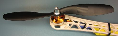
Этот шаг критически важен для стабильного полёта дрона. Если пропустить его, пропеллеры не будут стабильно работать, и дрон станет неуправляемым.
Установите пропеллеры на моторы и проверьте, что контрвесочные и часовые пропеллеры находятся в правильных позициях. Загрузите программу ESCCalibrate и откройте Serial Monitor на 57600 бод. Отправьте ‘1’ через Serial Monitor и дождитесь ответа «Test motor 1 (right front CCW)».
ESCCalibrate
//The program will start in calibration mode.
//Send the following characters / numbers via the serial monitor to change the mode
//
//r = print receiver signals.
//a = print quadcopter angles.
//1 = check rotation / vibrations for motor 1 (right front CCW).
//2 = check rotation / vibrations for motor 2 (right rear CW).
//3 = check rotation / vibrations for motor 3 (left rear CCW).
//4 = check rotation / vibrations for motor 4 (left front CW).
//5 = check vibrations for all motors together.
#include //Include the Wire.h library so we can communicate with the gyro.
#include //Include the EEPROM.h library so we can store information onto the EEPROM
//Declaring global variables
byte last_channel_1, last_channel_2, last_channel_3, last_channel_4;
byte eeprom_data[36], start, data;
boolean new_function_request,first_angle;
volatile int receiver_input_channel_1, receiver_input_channel_2, receiver_input_channel_3, receiver_input_channel_4;
int esc_1, esc_2, esc_3, esc_4;
int counter_channel_1, counter_channel_2, counter_channel_3, counter_channel_4;
int receiver_input[5];
int loop_counter, gyro_address, vibration_counter;
int temperature;
long acc_x, acc_y, acc_z, acc_total_vector[20], acc_av_vector, vibration_total_result;
unsigned long timer_channel_1, timer_channel_2, timer_channel_3, timer_channel_4, esc_timer, esc_loop_timer;
unsigned long zero_timer, timer_1, timer_2, timer_3, timer_4, current_time;
int acc_axis[4], gyro_axis[4];
double gyro_pitch, gyro_roll, gyro_yaw;
float angle_roll_acc, angle_pitch_acc, angle_pitch, angle_roll;
int cal_int;
double gyro_axis_cal[4];
//Setup routine
void setup(){
Serial.begin(9600); //Start the serial port.
Wire.begin(); //Start the wire library as master
TWBR = 12; //Set the I2C clock speed to 400kHz.
//Arduino Uno pins default to inputs, so they don't need to be explicitly declared as inputs.
DDRD |= B11110000; //Configure digital poort 4, 5, 6 and 7 as output.
DDRB |= B00010000; //Configure digital poort 12 as output.
PCICR |= (1 << PCIE0); // set PCIE0 to enable PCMSK0 scan.
PCMSK0 |= (1 << PCINT0); // set PCINT0 (digital input 8) to trigger an interrupt on state change.
PCMSK0 |= (1 << PCINT1); // set PCINT1 (digital input 9)to trigger an interrupt on state change.
PCMSK0 |= (1 << PCINT2); // set PCINT2 (digital input 10)to trigger an interrupt on state change.
PCMSK0 |= (1 << PCINT3); // set PCINT3 (digital input 11)to trigger an interrupt on state change.
for(data = 0; data <= 35; data++)eeprom_data[data] = EEPROM.read(data); //Read EEPROM for faster data access gyro_address = eeprom_data[32]; //Store the gyro address in the variable. set_gyro_registers(); //Set the specific gyro registers. //Check the EEPROM signature to make sure that the setup program is executed. while(eeprom_data[33] != 'J' || eeprom_data[34] != 'M' || eeprom_data[35] != 'B'){ delay(500); //Wait for 500ms. digitalWrite(12, !digitalRead(12)); //Change the led status to indicate error. } wait_for_receiver(); //Wait until the receiver is active. zero_timer = micros(); //Set the zero_timer for the first loop. while(Serial.available())data = Serial.read(); //Empty the serial buffer. data = 0; //Set the data variable back to zero. } //Main program loop void loop(){ while(zero_timer + 4000 > micros()); //Start the pulse after 4000 micro seconds.
zero_timer = micros(); //Reset the zero timer.
if(Serial.available() > 0){
data = Serial.read(); //Read the incomming byte.
delay(100); //Wait for any other bytes to come in
while(Serial.available() > 0)loop_counter = Serial.read(); //Empty the Serial buffer.
new_function_request = true; //Set the new request flag.
loop_counter = 0; //Reset the loop_counter variable.
cal_int = 0; //Reset the cal_int variable to undo the calibration.
start = 0; //Set start to 0.
first_angle = false; //Set first_angle to false.
//Confirm the choice on the serial monitor.
if(data == 'r')Serial.println("Reading receiver signals.");
if(data == 'a')Serial.println("Print the quadcopter angles.");
if(data == 'a')Serial.println("Gyro calibration starts in 2 seconds (don't move the quadcopter).");
if(data == '1')Serial.println("Test motor 1 (right front CCW.)");
if(data == '2')Serial.println("Test motor 2 (right rear CW.)");
if(data == '3')Serial.println("Test motor 3 (left rear CCW.)");
if(data == '4')Serial.println("Test motor 4 (left front CW.)");
if(data == '5')Serial.println("Test all motors together");
//Let's create a small delay so the message stays visible for 2.5 seconds.
//We don't want the ESC's to beep and have to send a 1000us pulse to the ESC's.
for(vibration_counter = 0; vibration_counter < 625; vibration_counter++){ //Do this loop 625 times
delay(3); //Wait 3000us.
esc_1 = 1000; //Set the pulse for ESC 1 to 1000us.
esc_2 = 1000; //Set the pulse for ESC 1 to 1000us.
esc_3 = 1000; //Set the pulse for ESC 1 to 1000us.
esc_4 = 1000; //Set the pulse for ESC 1 to 1000us.
esc_pulse_output(); //Send the ESC control pulses.
}
vibration_counter = 0; //Reset the vibration_counter variable.
}
receiver_input_channel_3 = convert_receiver_channel(3); //Convert the actual receiver signals for throttle to the standard 1000 - 2000us.
if(receiver_input_channel_3 < 1025)new_function_request = false; //If the throttle is in the lowest position set the request flag to false.
////////////////////////////////////////////////////////////////////////////////////////////
//Run the ESC calibration program to start with.
////////////////////////////////////////////////////////////////////////////////////////////
if(data == 0 && new_function_request == false){ //Only start the calibration mode at first start.
receiver_input_channel_3 = convert_receiver_channel(3); //Convert the actual receiver signals for throttle to the standard 1000 - 2000us.
esc_1 = receiver_input_channel_3; //Set the pulse for motor 1 equal to the throttle channel.
esc_2 = receiver_input_channel_3; //Set the pulse for motor 2 equal to the throttle channel.
esc_3 = receiver_input_channel_3; //Set the pulse for motor 3 equal to the throttle channel.
esc_4 = receiver_input_channel_3; //Set the pulse for motor 4 equal to the throttle channel.
esc_pulse_output(); //Send the ESC control pulses.
}
////////////////////////////////////////////////////////////////////////////////////////////
//When user sends a 'r' print the receiver signals.
////////////////////////////////////////////////////////////////////////////////////////////
if(data == 'r'){
loop_counter ++; //Increase the loop_counter variable.
receiver_input_channel_1 = convert_receiver_channel(1); //Convert the actual receiver signals for pitch to the standard 1000 - 2000us.
receiver_input_channel_2 = convert_receiver_channel(2); //Convert the actual receiver signals for roll to the standard 1000 - 2000us.
receiver_input_channel_3 = convert_receiver_channel(3); //Convert the actual receiver signals for throttle to the standard 1000 - 2000us.
receiver_input_channel_4 = convert_receiver_channel(4); //Convert the actual receiver signals for yaw to the standard 1000 - 2000us.
if(loop_counter == 125){ //Print the receiver values when the loop_counter variable equals 250.
print_signals(); //Print the receiver values on the serial monitor.
loop_counter = 0; //Reset the loop_counter variable.
}
//For starting the motors: throttle low and yaw left (step 1).
if(receiver_input_channel_3 < 1050 && receiver_input_channel_4 < 1050)start = 1;
//When yaw stick is back in the center position start the motors (step 2).
if(start == 1 && receiver_input_channel_3 < 1050 && receiver_input_channel_4 > 1450)start = 2;
//Stopping the motors: throttle low and yaw right.
if(start == 2 && receiver_input_channel_3 < 1050 && receiver_input_channel_4 > 1950)start = 0;
esc_1 = 1000; //Set the pulse for ESC 1 to 1000us.
esc_2 = 1000; //Set the pulse for ESC 1 to 1000us.
esc_3 = 1000; //Set the pulse for ESC 1 to 1000us.
esc_4 = 1000; //Set the pulse for ESC 1 to 1000us.
esc_pulse_output(); //Send the ESC control pulses.
}
///////////////////////////////////////////////////////////////////////////////////////////
//When user sends a '1, 2, 3, 4 or 5 test the motors.
////////////////////////////////////////////////////////////////////////////////////////////
if(data == '1' || data == '2' || data == '3' || data == '4' || data == '5'){ //If motor 1, 2, 3 or 4 is selected by the user.
loop_counter ++; //Add 1 to the loop_counter variable.
if(new_function_request == true && loop_counter == 250){ //Wait for the throttle to be set to 0.
Serial.print("Set throttle to 1000 (low). It's now set to: "); //Print message on the serial monitor.
Serial.println(receiver_input_channel_3); //Print the actual throttle position.
loop_counter = 0; //Reset the loop_counter variable.
}
if(new_function_request == false){ //When the throttle was in the lowest position do this.
receiver_input_channel_3 = convert_receiver_channel(3); //Convert the actual receiver signals for throttle to the standard 1000 - 2000us.
if(data == '1' || data == '5')esc_1 = receiver_input_channel_3; //If motor 1 is requested set the pulse for motor 1 equal to the throttle channel.
else esc_1 = 1000; //If motor 1 is not requested set the pulse for the ESC to 1000us (off).
if(data == '2' || data == '5')esc_2 = receiver_input_channel_3; //If motor 2 is requested set the pulse for motor 1 equal to the throttle channel.
else esc_2 = 1000; //If motor 2 is not requested set the pulse for the ESC to 1000us (off).
if(data == '3' || data == '5')esc_3 = receiver_input_channel_3; //If motor 3 is requested set the pulse for motor 1 equal to the throttle channel.
else esc_3 = 1000; //If motor 3 is not requested set the pulse for the ESC to 1000us (off).
if(data == '4' || data == '5')esc_4 = receiver_input_channel_3; //If motor 4 is requested set the pulse for motor 1 equal to the throttle channel.
else esc_4 = 1000; //If motor 4 is not requested set the pulse for the ESC to 1000us (off).
esc_pulse_output(); //Send the ESC control pulses.
//For balancing the propellors it's possible to use the accelerometer to measure the vibrations.
if(eeprom_data[31] == 1){ //The MPU-6050 is installed
Wire.beginTransmission(gyro_address); //Start communication with the gyro.
Wire.write(0x3B); //Start reading @ register 43h and auto increment with every read.
Wire.endTransmission(); //End the transmission.
Wire.requestFrom(gyro_address,6); //Request 6 bytes from the gyro.
while(Wire.available() < 6); //Wait until the 6 bytes are received.
acc_x = Wire.read()<<8|Wire.read(); //Add the low and high byte to the acc_x variable.
acc_y = Wire.read()<<8|Wire.read(); //Add the low and high byte to the acc_y variable.
acc_z = Wire.read()<<8|Wire.read(); //Add the low and high byte to the acc_z variable. acc_total_vector[0] = sqrt((acc_x*acc_x)+(acc_y*acc_y)+(acc_z*acc_z)); //Calculate the total accelerometer vector. acc_av_vector = acc_total_vector[0]; //Copy the total vector to the accelerometer average vector variable. for(start = 16; start > 0; start--){ //Do this loop 16 times to create an array of accelrometer vectors.
acc_total_vector[start] = acc_total_vector[start - 1]; //Shift every variable one position up in the array.
acc_av_vector += acc_total_vector[start]; //Add the array value to the acc_av_vector variable.
}
acc_av_vector /= 17; //Divide the acc_av_vector by 17 to get the avarage total accelerometer vector.
if(vibration_counter < 20){ //If the vibration_counter is less than 20 do this.
vibration_counter ++; //Increment the vibration_counter variable.
vibration_total_result += abs(acc_total_vector[0] - acc_av_vector); //Add the absolute difference between the avarage vector and current vector to the vibration_total_result variable.
}
else{
vibration_counter = 0; //If the vibration_counter is equal or larger than 20 do this.
Serial.println(vibration_total_result/50); //Print the total accelerometer vector divided by 50 on the serial monitor.
vibration_total_result = 0; //Reset the vibration_total_result variable.
}
}
}
}
///////////////////////////////////////////////////////////////////////////////////////////
//When user sends a 'a' display the quadcopter angles.
////////////////////////////////////////////////////////////////////////////////////////////
if(data == 'a'){
if(cal_int != 2000){
Serial.print("Calibrating the gyro");
//Let's take multiple gyro data samples so we can determine the average gyro offset (calibration).
for (cal_int = 0; cal_int < 2000 ; cal_int ++){ //Take 2000 readings for calibration.
if(cal_int % 125 == 0){
digitalWrite(12, !digitalRead(12)); //Change the led status to indicate calibration.
Serial.print(".");
}
gyro_signalen(); //Read the gyro output.
gyro_axis_cal[1] += gyro_axis[1]; //Ad roll value to gyro_roll_cal.
gyro_axis_cal[2] += gyro_axis[2]; //Ad pitch value to gyro_pitch_cal.
gyro_axis_cal[3] += gyro_axis[3]; //Ad yaw value to gyro_yaw_cal.
//We don't want the esc's to be beeping annoyingly. So let's give them a 1000us puls while calibrating the gyro.
PORTD |= B11110000; //Set digital poort 4, 5, 6 and 7 high.
delayMicroseconds(1000); //Wait 1000us.
PORTD &= B00001111; //Set digital poort 4, 5, 6 and 7 low.
delay(3); //Wait 3 milliseconds before the next loop.
}
Serial.println(".");
//Now that we have 2000 measures, we need to devide by 2000 to get the average gyro offset.
gyro_axis_cal[1] /= 2000; //Divide the roll total by 2000.
gyro_axis_cal[2] /= 2000; //Divide the pitch total by 2000.
gyro_axis_cal[3] /= 2000; //Divide the yaw total by 2000.
}
else{
///We don't want the esc's to be beeping annoyingly. So let's give them a 1000us puls while calibrating the gyro.
PORTD |= B11110000; //Set digital poort 4, 5, 6 and 7 high.
delayMicroseconds(1000); //Wait 1000us.
PORTD &= B00001111; //Set digital poort 4, 5, 6 and 7 low.
//Let's get the current gyro data.
gyro_signalen();
//Gyro angle calculations
//0.0000611 = 1 / (250Hz / 65.5)
angle_pitch += gyro_pitch * 0.0000611; //Calculate the traveled pitch angle and add this to the angle_pitch variable.
angle_roll += gyro_roll * 0.0000611; //Calculate the traveled roll angle and add this to the angle_roll variable.
//0.000001066 = 0.0000611 * (3.142(PI) / 180degr) The Arduino sin function is in radians
angle_pitch -= angle_roll * sin(gyro_yaw * 0.000001066); //If the IMU has yawed transfer the roll angle to the pitch angel.
angle_roll += angle_pitch * sin(gyro_yaw * 0.000001066); //If the IMU has yawed transfer the pitch angle to the roll angel.
//Accelerometer angle calculations
acc_total_vector[0] = sqrt((acc_x*acc_x)+(acc_y*acc_y)+(acc_z*acc_z)); //Calculate the total accelerometer vector.
//57.296 = 1 / (3.142 / 180) The Arduino asin function is in radians
angle_pitch_acc = asin((float)acc_y/acc_total_vector[0])* 57.296; //Calculate the pitch angle.
angle_roll_acc = asin((float)acc_x/acc_total_vector[0])* -57.296; //Calculate the roll angle.
if(!first_angle){
angle_pitch = angle_pitch_acc; //Set the pitch angle to the accelerometer angle.
angle_roll = angle_roll_acc; //Set the roll angle to the accelerometer angle.
first_angle = true;
}
else{
angle_pitch = angle_pitch * 0.9996 + angle_pitch_acc * 0.0004; //Correct the drift of the gyro pitch angle with the accelerometer pitch angle.
angle_roll = angle_roll * 0.9996 + angle_roll_acc * 0.0004; //Correct the drift of the gyro roll angle with the accelerometer roll angle.
}
//We can't print all the data at once. This takes to long and the angular readings will be off.
if(loop_counter == 0)Serial.print("Pitch: ");
if(loop_counter == 1)Serial.print(angle_pitch ,0);
if(loop_counter == 2)Serial.print(" Roll: ");
if(loop_counter == 3)Serial.print(angle_roll ,0);
if(loop_counter == 4)Serial.print(" Yaw: ");
if(loop_counter == 5)Serial.println(gyro_yaw / 65.5 ,0);
loop_counter ++;
if(loop_counter == 60)loop_counter = 0;
}
}
}
//This routine is called every time input 8, 9, 10 or 11 changed state.
ISR(PCINT0_vect){
current_time = micros();
//Channel 1=========================================
if(PINB & B00000001){ //Is input 8 high?
if(last_channel_1 == 0){ //Input 8 changed from 0 to 1.
last_channel_1 = 1; //Remember current input state.
timer_1 = current_time; //Set timer_1 to current_time.
}
}
else if(last_channel_1 == 1){ //Input 8 is not high and changed from 1 to 0.
last_channel_1 = 0; //Remember current input state.
receiver_input[1] = current_time - timer_1; //Channel 1 is current_time - timer_1.
}
//Channel 2=========================================
if(PINB & B00000010 ){ //Is input 9 high?
if(last_channel_2 == 0){ //Input 9 changed from 0 to 1.
last_channel_2 = 1; //Remember current input state.
timer_2 = current_time; //Set timer_2 to current_time.
}
}
else if(last_channel_2 == 1){ //Input 9 is not high and changed from 1 to 0.
last_channel_2 = 0; //Remember current input state.
receiver_input[2] = current_time - timer_2; //Channel 2 is current_time - timer_2.
}
//Channel 3=========================================
if(PINB & B00000100 ){ //Is input 10 high?
if(last_channel_3 == 0){ //Input 10 changed from 0 to 1.
last_channel_3 = 1; //Remember current input state.
timer_3 = current_time; //Set timer_3 to current_time.
}
}
else if(last_channel_3 == 1){ //Input 10 is not high and changed from 1 to 0.
last_channel_3 = 0; //Remember current input state.
receiver_input[3] = current_time - timer_3; //Channel 3 is current_time - timer_3.
}
//Channel 4=========================================
if(PINB & B00001000 ){ //Is input 11 high?
if(last_channel_4 == 0){ //Input 11 changed from 0 to 1.
last_channel_4 = 1; //Remember current input state.
timer_4 = current_time; //Set timer_4 to current_time.
}
}
else if(last_channel_4 == 1){ //Input 11 is not high and changed from 1 to 0.
last_channel_4 = 0; //Remember current input state.
receiver_input[4] = current_time - timer_4; //Channel 4 is current_time - timer_4.
}
}
//Checck if the receiver values are valid within 10 seconds
void wait_for_receiver(){
byte zero = 0; //Set all bits in the variable zero to 0
while(zero < 15){ //Stay in this loop until the 4 lowest bits are set
if(receiver_input[1] < 2100 && receiver_input[1] > 900)zero |= 0b00000001; //Set bit 0 if the receiver pulse 1 is within the 900 - 2100 range
if(receiver_input[2] < 2100 && receiver_input[2] > 900)zero |= 0b00000010; //Set bit 1 if the receiver pulse 2 is within the 900 - 2100 range
if(receiver_input[3] < 2100 && receiver_input[3] > 900)zero |= 0b00000100; //Set bit 2 if the receiver pulse 3 is within the 900 - 2100 range
if(receiver_input[4] < 2100 && receiver_input[4] > 900)zero |= 0b00001000; //Set bit 3 if the receiver pulse 4 is within the 900 - 2100 range
delay(500); //Wait 500 milliseconds
}
}
//This part converts the actual receiver signals to a standardized 1000 – 1500 – 2000 microsecond value.
//The stored data in the EEPROM is used.
int convert_receiver_channel(byte function){
byte channel, reverse; //First we declare some local variables
int low, center, high, actual;
int difference;
channel = eeprom_data[function + 23] & 0b00000111; //What channel corresponds with the specific function
if(eeprom_data[function + 23] & 0b10000000)reverse = 1; //Reverse channel when most significant bit is set
else reverse = 0; //If the most significant is not set there is no reverse
actual = receiver_input[channel]; //Read the actual receiver value for the corresponding function
low = (eeprom_data[channel * 2 + 15] << 8) | eeprom_data[channel * 2 + 14]; //Store the low value for the specific receiver input channel
center = (eeprom_data[channel * 2 - 1] << 8) | eeprom_data[channel * 2 - 2]; //Store the center value for the specific receiver input channel
high = (eeprom_data[channel * 2 + 7] << 8) | eeprom_data[channel * 2 + 6]; //Store the high value for the specific receiver input channel
if(actual < center){ //The actual receiver value is lower than the center value
if(actual < low)actual = low; //Limit the lowest value to the value that was detected during setup difference = ((long)(center - actual) * (long)500) / (center - low); //Calculate and scale the actual value to a 1000 - 2000us value if(reverse == 1)return 1500 + difference; //If the channel is reversed else return 1500 - difference; //If the channel is not reversed } else if(actual > center){ //The actual receiver value is higher than the center value
if(actual > high)actual = high; //Limit the lowest value to the value that was detected during setup
difference = ((long)(actual - center) * (long)500) / (high - center); //Calculate and scale the actual value to a 1000 - 2000us value
if(reverse == 1)return 1500 - difference; //If the channel is reversed
else return 1500 + difference; //If the channel is not reversed
}
else return 1500;
}
void print_signals(){
Serial.print("Start:");
Serial.print(start);
Serial.print(" Roll:");
if(receiver_input_channel_1 - 1480 < 0)Serial.print("<<<"); else if(receiver_input_channel_1 - 1520 > 0)Serial.print(">>>");
else Serial.print("-+-");
Serial.print(receiver_input_channel_1);
Serial.print(" Pitch:");
if(receiver_input_channel_2 - 1480 < 0)Serial.print("^^^"); else if(receiver_input_channel_2 - 1520 > 0)Serial.print("vvv");
else Serial.print("-+-");
Serial.print(receiver_input_channel_2);
Serial.print(" Throttle:");
if(receiver_input_channel_3 - 1480 < 0)Serial.print("vvv"); else if(receiver_input_channel_3 - 1520 > 0)Serial.print("^^^");
else Serial.print("-+-");
Serial.print(receiver_input_channel_3);
Serial.print(" Yaw:");
if(receiver_input_channel_4 - 1480 < 0)Serial.print("<<<"); else if(receiver_input_channel_4 - 1520 > 0)Serial.print(">>>");
else Serial.print("-+-");
Serial.println(receiver_input_channel_4);
}
void esc_pulse_output(){
zero_timer = micros();
PORTD |= B11110000; //Set port 4, 5, 6 and 7 high at once
timer_channel_1 = esc_1 + zero_timer; //Calculate the time when digital port 4 is set low.
timer_channel_2 = esc_2 + zero_timer; //Calculate the time when digital port 5 is set low.
timer_channel_3 = esc_3 + zero_timer; //Calculate the time when digital port 6 is set low.
timer_channel_4 = esc_4 + zero_timer; //Calculate the time when digital port 7 is set low.
while(PORTD >= 16){ //Execute the loop until digital port 4 to 7 is low.
esc_loop_timer = micros(); //Check the current time.
if(timer_channel_1 <= esc_loop_timer)PORTD &= B11101111; //When the delay time is expired, digital port 4 is set low.
if(timer_channel_2 <= esc_loop_timer)PORTD &= B11011111; //When the delay time is expired, digital port 5 is set low.
if(timer_channel_3 <= esc_loop_timer)PORTD &= B10111111; //When the delay time is expired, digital port 6 is set low.
if(timer_channel_4 <= esc_loop_timer)PORTD &= B01111111; //When the delay time is expired, digital port 7 is set low.
}
}
void set_gyro_registers(){
//Setup the MPU-6050
if(eeprom_data[31] == 1){
Wire.beginTransmission(gyro_address); //Start communication with the address found during search.
Wire.write(0x6B); //We want to write to the PWR_MGMT_1 register (6B hex)
Wire.write(0x00); //Set the register bits as 00000000 to activate the gyro
Wire.endTransmission(); //End the transmission with the gyro.
Wire.beginTransmission(gyro_address); //Start communication with the address found during search.
Wire.write(0x1B); //We want to write to the GYRO_CONFIG register (1B hex)
Wire.write(0x08); //Set the register bits as 00001000 (500dps full scale)
Wire.endTransmission(); //End the transmission with the gyro
Wire.beginTransmission(gyro_address); //Start communication with the address found during search.
Wire.write(0x1C); //We want to write to the ACCEL_CONFIG register (1A hex)
Wire.write(0x10); //Set the register bits as 00010000 (+/- 8g full scale range)
Wire.endTransmission(); //End the transmission with the gyro
//Let's perform a random register check to see if the values are written correct
Wire.beginTransmission(gyro_address); //Start communication with the address found during search
Wire.write(0x1B); //Start reading @ register 0x1B
Wire.endTransmission(); //End the transmission
Wire.requestFrom(gyro_address, 1); //Request 1 bytes from the gyro
while(Wire.available() < 1); //Wait until the 6 bytes are received
if(Wire.read() != 0x08){ //Check if the value is 0x08
digitalWrite(12,HIGH); //Turn on the warning led
while(1)delay(10); //Stay in this loop for ever
}
Wire.beginTransmission(gyro_address); //Start communication with the address found during search
Wire.write(0x1A); //We want to write to the CONFIG register (1A hex)
Wire.write(0x03); //Set the register bits as 00000011 (Set Digital Low Pass Filter to ~43Hz)
Wire.endTransmission(); //End the transmission with the gyro
}
}
void gyro_signalen(){
//Read the MPU-6050
if(eeprom_data[31] == 1){
Wire.beginTransmission(gyro_address); //Start communication with the gyro.
Wire.write(0x3B); //Start reading @ register 43h and auto increment with every read.
Wire.endTransmission(); //End the transmission.
Wire.requestFrom(gyro_address,14); //Request 14 bytes from the gyro.
while(Wire.available() < 14); //Wait until the 14 bytes are received.
acc_axis[1] = Wire.read()<<8|Wire.read(); //Add the low and high byte to the acc_x variable.
acc_axis[2] = Wire.read()<<8|Wire.read(); //Add the low and high byte to the acc_y variable.
acc_axis[3] = Wire.read()<<8|Wire.read(); //Add the low and high byte to the acc_z variable.
temperature = Wire.read()<<8|Wire.read(); //Add the low and high byte to the temperature variable.
gyro_axis[1] = Wire.read()<<8|Wire.read(); //Read high and low part of the angular data.
gyro_axis[2] = Wire.read()<<8|Wire.read(); //Read high and low part of the angular data.
gyro_axis[3] = Wire.read()<<8|Wire.read(); //Read high and low part of the angular data.
}
if(cal_int == 2000){
gyro_axis[1] -= gyro_axis_cal[1]; //Only compensate after the calibration.
gyro_axis[2] -= gyro_axis_cal[2]; //Only compensate after the calibration.
gyro_axis[3] -= gyro_axis_cal[3]; //Only compensate after the calibration.
}
gyro_roll = gyro_axis[eeprom_data[28] & 0b00000011]; //Set gyro_roll to the correct axis that was stored in the EEPROM.
if(eeprom_data[28] & 0b10000000)gyro_roll *= -1; //Invert gyro_roll if the MSB of EEPROM bit 28 is set.
gyro_pitch = gyro_axis[eeprom_data[29] & 0b00000011]; //Set gyro_pitch to the correct axis that was stored in the EEPROM.
if(eeprom_data[29] & 0b10000000)gyro_pitch *= -1; //Invert gyro_pitch if the MSB of EEPROM bit 29 is set.
gyro_yaw = gyro_axis[eeprom_data[30] & 0b00000011]; //Set gyro_yaw to the correct axis that was stored in the EEPROM.
if(eeprom_data[30] & 0b10000000)gyro_yaw *= -1; //Invert gyro_yaw if the MSB of EEPROM bit 30 is set.
acc_x = acc_axis[eeprom_data[29] & 0b00000011]; //Set acc_x to the correct axis that was stored in the EEPROM.
if(eeprom_data[29] & 0b10000000)acc_x *= -1; //Invert acc_x if the MSB of EEPROM bit 29 is set.
acc_y = acc_axis[eeprom_data[28] & 0b00000011]; //Set acc_y to the correct axis that was stored in the EEPROM.
if(eeprom_data[28] & 0b10000000)acc_y *= -1; //Invert acc_y if the MSB of EEPROM bit 28 is set.
acc_z = acc_axis[eeprom_data[30] & 0b00000011]; //Set acc_z to the correct axis that was stored in the EEPROM.
if(eeprom_data[30] & 0b10000000)acc_z *= -1; //Invert acc_z if the MSB of EEPROM bit 30 is set.
}
Числа на экране представляют собой количество вибраций, измеренных акселерометром. Держите раму мотора крепко в руках и увеличивайте дроссель до половины. Проверьте числа на экране и запомните вибрации, которые ощущаете рукой.
Шаг 6: Программирование дрона. Часть 2
Этот шаг легко выполнить. Скачайте скетч FlightController и загрузите его в дрон. Затем отключите дрон и подключите аккумулятор. Вы должны услышать серию звуков «Beep beep beep BEEEEP!». Если слышите этот набор, всё в порядке. Если нет, значит, вы неправильно очистили EEPROM.
FlightController
#include //Include the Wire.h library so we can communicate with the gyro.
#include //Include the EEPROM.h library so we can store information onto the EEPROM
///////////////////////////////////////////////////////////////////////////////////////////////////////////////////////////////////////
//PID gain and limit settings
///////////////////////////////////////////////////////////////////////////////////////////////////////////////////////////////////////
float pid_p_gain_roll = 1.3; //Gain setting for the roll P-controller
float pid_i_gain_roll = 0.04; //Gain setting for the roll I-controller
float pid_d_gain_roll = 18.0; //Gain setting for the roll D-controller
int pid_max_roll = 400; //Maximum output of the PID-controller (+/-)
float pid_p_gain_pitch = pid_p_gain_roll; //Gain setting for the pitch P-controller.
float pid_i_gain_pitch = pid_i_gain_roll; //Gain setting for the pitch I-controller.
float pid_d_gain_pitch = pid_d_gain_roll; //Gain setting for the pitch D-controller.
int pid_max_pitch = pid_max_roll; //Maximum output of the PID-controller (+/-)
float pid_p_gain_yaw = 4.0; //Gain setting for the pitch P-controller. //4.0
float pid_i_gain_yaw = 0.02; //Gain setting for the pitch I-controller. //0.02
float pid_d_gain_yaw = 0.0; //Gain setting for the pitch D-controller.
int pid_max_yaw = 400; //Maximum output of the PID-controller (+/-)
boolean auto_level = true; //Auto level on (true) or off (false)
///////////////////////////////////////////////////////////////////////////////////////////////////////////////////////////////////////
//Declaring global variables
///////////////////////////////////////////////////////////////////////////////////////////////////////////////////////////////////////
byte last_channel_1, last_channel_2, last_channel_3, last_channel_4;
byte eeprom_data[36];
byte highByte, lowByte;
volatile int receiver_input_channel_1, receiver_input_channel_2, receiver_input_channel_3, receiver_input_channel_4;
int counter_channel_1, counter_channel_2, counter_channel_3, counter_channel_4, loop_counter;
int esc_1, esc_2, esc_3, esc_4;
int throttle, battery_voltage;
int cal_int, start, gyro_address;
int receiver_input[5];
int temperature;
int acc_axis[4], gyro_axis[4];
float roll_level_adjust, pitch_level_adjust;
long acc_x, acc_y, acc_z, acc_total_vector;
unsigned long timer_channel_1, timer_channel_2, timer_channel_3, timer_channel_4, esc_timer, esc_loop_timer;
unsigned long timer_1, timer_2, timer_3, timer_4, current_time;
unsigned long loop_timer;
double gyro_pitch, gyro_roll, gyro_yaw;
double gyro_axis_cal[4];
float pid_error_temp;
float pid_i_mem_roll, pid_roll_setpoint, gyro_roll_input, pid_output_roll, pid_last_roll_d_error;
float pid_i_mem_pitch, pid_pitch_setpoint, gyro_pitch_input, pid_output_pitch, pid_last_pitch_d_error;
float pid_i_mem_yaw, pid_yaw_setpoint, gyro_yaw_input, pid_output_yaw, pid_last_yaw_d_error;
float angle_roll_acc, angle_pitch_acc, angle_pitch, angle_roll;
boolean gyro_angles_set;
///////////////////////////////////////////////////////////////////////////////////////////////////////////////////////////////////////
//Setup routine
///////////////////////////////////////////////////////////////////////////////////////////////////////////////////////////////////////
void setup(){
//Serial.begin(57600);
//Copy the EEPROM data for fast access data.
for(start = 0; start <= 35; start++)eeprom_data[start] = EEPROM.read(start);
start = 0; //Set start back to zero.
gyro_address = eeprom_data[32]; //Store the gyro address in the variable.
Wire.begin(); //Start the I2C as master.
TWBR = 12; //Set the I2C clock speed to 400kHz.
//Arduino (Atmega) pins default to inputs, so they don't need to be explicitly declared as inputs.
DDRD |= B11110000; //Configure digital poort 4, 5, 6 and 7 as output.
DDRB |= B00110000; //Configure digital poort 12 and 13 as output.
//Use the led on the Arduino for startup indication.
digitalWrite(12,HIGH); //Turn on the warning led.
//Check the EEPROM signature to make sure that the setup program is executed.
while(eeprom_data[33] != 'J' || eeprom_data[34] != 'M' || eeprom_data[35] != 'B')delay(10);
//The flight controller needs the MPU-6050 with gyro and accelerometer
//If setup is completed without MPU-6050 stop the flight controller program
if(eeprom_data[31] == 2 || eeprom_data[31] == 3)delay(10);
set_gyro_registers(); //Set the specific gyro registers.
for (cal_int = 0; cal_int < 1250 ; cal_int ++){ //Wait 5 seconds before continuing.
PORTD |= B11110000; //Set digital poort 4, 5, 6 and 7 high.
delayMicroseconds(1000); //Wait 1000us.
PORTD &= B00001111; //Set digital poort 4, 5, 6 and 7 low.
delayMicroseconds(3000); //Wait 3000us.
}
//Let's take multiple gyro data samples so we can determine the average gyro offset (calibration).
for (cal_int = 0; cal_int < 2000 ; cal_int ++){ //Take 2000 readings for calibration.
if(cal_int % 15 == 0)digitalWrite(12, !digitalRead(12)); //Change the led status to indicate calibration.
gyro_signalen(); //Read the gyro output.
gyro_axis_cal[1] += gyro_axis[1]; //Ad roll value to gyro_roll_cal.
gyro_axis_cal[2] += gyro_axis[2]; //Ad pitch value to gyro_pitch_cal.
gyro_axis_cal[3] += gyro_axis[3]; //Ad yaw value to gyro_yaw_cal.
//We don't want the esc's to be beeping annoyingly. So let's give them a 1000us puls while calibrating the gyro.
PORTD |= B11110000; //Set digital poort 4, 5, 6 and 7 high.
delayMicroseconds(1000); //Wait 1000us.
PORTD &= B00001111; //Set digital poort 4, 5, 6 and 7 low.
delay(3); //Wait 3 milliseconds before the next loop.
}
//Now that we have 2000 measures, we need to devide by 2000 to get the average gyro offset.
gyro_axis_cal[1] /= 2000; //Divide the roll total by 2000.
gyro_axis_cal[2] /= 2000; //Divide the pitch total by 2000.
gyro_axis_cal[3] /= 2000; //Divide the yaw total by 2000.
PCICR |= (1 << PCIE0); //Set PCIE0 to enable PCMSK0 scan.
PCMSK0 |= (1 << PCINT0); //Set PCINT0 (digital input 8) to trigger an interrupt on state change.
PCMSK0 |= (1 << PCINT1); //Set PCINT1 (digital input 9)to trigger an interrupt on state change.
PCMSK0 |= (1 << PCINT2); //Set PCINT2 (digital input 10)to trigger an interrupt on state change.
PCMSK0 |= (1 << PCINT3); //Set PCINT3 (digital input 11)to trigger an interrupt on state change.
//Wait until the receiver is active and the throtle is set to the lower position.
while(receiver_input_channel_3 < 990 || receiver_input_channel_3 > 1020 || receiver_input_channel_4 < 1400){
receiver_input_channel_3 = convert_receiver_channel(3); //Convert the actual receiver signals for throttle to the standard 1000 - 2000us
receiver_input_channel_4 = convert_receiver_channel(4); //Convert the actual receiver signals for yaw to the standard 1000 - 2000us
start ++; //While waiting increment start whith every loop.
//We don't want the esc's to be beeping annoyingly. So let's give them a 1000us puls while waiting for the receiver inputs.
PORTD |= B11110000; //Set digital poort 4, 5, 6 and 7 high.
delayMicroseconds(1000); //Wait 1000us.
PORTD &= B00001111; //Set digital poort 4, 5, 6 and 7 low.
delay(3); //Wait 3 milliseconds before the next loop.
if(start == 125){ //Every 125 loops (500ms).
digitalWrite(12, !digitalRead(12)); //Change the led status.
start = 0; //Start again at 0.
}
}
start = 0; //Set start back to 0.
//Load the battery voltage to the battery_voltage variable.
//65 is the voltage compensation for the diode.
//12.6V equals ~5V @ Analog 0.
//12.6V equals 1023 analogRead(0).
//1260 / 1023 = 1.2317.
//The variable battery_voltage holds 1050 if the battery voltage is 10.5V.
battery_voltage = (analogRead(0) + 65) * 1.2317;
loop_timer = micros(); //Set the timer for the next loop.
//When everything is done, turn off the led.
digitalWrite(12,LOW); //Turn off the warning led.
}
///////////////////////////////////////////////////////////////////////////////////////////////////////////////////////////////////////
//Main program loop
///////////////////////////////////////////////////////////////////////////////////////////////////////////////////////////////////////
void loop(){
//65.5 = 1 deg/sec (check the datasheet of the MPU-6050 for more information).
gyro_roll_input = (gyro_roll_input * 0.7) + ((gyro_roll / 65.5) * 0.3); //Gyro pid input is deg/sec.
gyro_pitch_input = (gyro_pitch_input * 0.7) + ((gyro_pitch / 65.5) * 0.3);//Gyro pid input is deg/sec.
gyro_yaw_input = (gyro_yaw_input * 0.7) + ((gyro_yaw / 65.5) * 0.3); //Gyro pid input is deg/sec.
//Gyro angle calculations
//0.0000611 = 1 / (250Hz / 65.5)
angle_pitch += gyro_pitch * 0.0000611; //Calculate the traveled pitch angle and add this to the angle_pitch variable.
angle_roll += gyro_roll * 0.0000611; //Calculate the traveled roll angle and add this to the angle_roll variable.
//0.000001066 = 0.0000611 * (3.142(PI) / 180degr) The Arduino sin function is in radians
angle_pitch -= angle_roll * sin(gyro_yaw * 0.000001066); //If the IMU has yawed transfer the roll angle to the pitch angel.
angle_roll += angle_pitch * sin(gyro_yaw * 0.000001066); //If the IMU has yawed transfer the pitch angle to the roll angel.
//Accelerometer angle calculations
acc_total_vector = sqrt((acc_x*acc_x)+(acc_y*acc_y)+(acc_z*acc_z)); //Calculate the total accelerometer vector.
if(abs(acc_y) < acc_total_vector){ //Prevent the asin function to produce a NaN
angle_pitch_acc = asin((float)acc_y/acc_total_vector)* 57.296; //Calculate the pitch angle.
}
if(abs(acc_x) < acc_total_vector){ //Prevent the asin function to produce a NaN
angle_roll_acc = asin((float)acc_x/acc_total_vector)* -57.296; //Calculate the roll angle.
}
//Place the MPU-6050 spirit level and note the values in the following two lines for calibration.
angle_pitch_acc -= 0.0; //Accelerometer calibration value for pitch.
angle_roll_acc -= 0.0; //Accelerometer calibration value for roll.
angle_pitch = angle_pitch * 0.9996 + angle_pitch_acc * 0.0004; //Correct the drift of the gyro pitch angle with the accelerometer pitch angle.
angle_roll = angle_roll * 0.9996 + angle_roll_acc * 0.0004; //Correct the drift of the gyro roll angle with the accelerometer roll angle.
pitch_level_adjust = angle_pitch * 15; //Calculate the pitch angle correction
roll_level_adjust = angle_roll * 15; //Calculate the roll angle correction
if(!auto_level){ //If the quadcopter is not in auto-level mode
pitch_level_adjust = 0; //Set the pitch angle correction to zero.
roll_level_adjust = 0; //Set the roll angle correcion to zero.
}
//For starting the motors: throttle low and yaw left (step 1).
if(receiver_input_channel_3 < 1050 && receiver_input_channel_4 < 1050)start = 1;
//When yaw stick is back in the center position start the motors (step 2).
if(start == 1 && receiver_input_channel_3 < 1050 && receiver_input_channel_4 > 1450){
start = 2;
angle_pitch = angle_pitch_acc; //Set the gyro pitch angle equal to the accelerometer pitch angle when the quadcopter is started.
angle_roll = angle_roll_acc; //Set the gyro roll angle equal to the accelerometer roll angle when the quadcopter is started.
gyro_angles_set = true; //Set the IMU started flag.
//Reset the PID controllers for a bumpless start.
pid_i_mem_roll = 0;
pid_last_roll_d_error = 0;
pid_i_mem_pitch = 0;
pid_last_pitch_d_error = 0;
pid_i_mem_yaw = 0;
pid_last_yaw_d_error = 0;
}
//Stopping the motors: throttle low and yaw right.
if(start == 2 && receiver_input_channel_3 < 1050 && receiver_input_channel_4 > 1950)start = 0;
//The PID set point in degrees per second is determined by the roll receiver input.
//In the case of deviding by 3 the max roll rate is aprox 164 degrees per second ( (500-8)/3 = 164d/s ).
pid_roll_setpoint = 0;
//We need a little dead band of 16us for better results.
if(receiver_input_channel_1 > 1508)pid_roll_setpoint = receiver_input_channel_1 - 1508;
else if(receiver_input_channel_1 < 1492)pid_roll_setpoint = receiver_input_channel_1 - 1492; pid_roll_setpoint -= roll_level_adjust; //Subtract the angle correction from the standardized receiver roll input value. pid_roll_setpoint /= 3.0; //Divide the setpoint for the PID roll controller by 3 to get angles in degrees. //The PID set point in degrees per second is determined by the pitch receiver input. //In the case of deviding by 3 the max pitch rate is aprox 164 degrees per second ( (500-8)/3 = 164d/s ). pid_pitch_setpoint = 0; //We need a little dead band of 16us for better results. if(receiver_input_channel_2 > 1508)pid_pitch_setpoint = receiver_input_channel_2 - 1508;
else if(receiver_input_channel_2 < 1492)pid_pitch_setpoint = receiver_input_channel_2 - 1492; pid_pitch_setpoint -= pitch_level_adjust; //Subtract the angle correction from the standardized receiver pitch input value. pid_pitch_setpoint /= 3.0; //Divide the setpoint for the PID pitch controller by 3 to get angles in degrees. //The PID set point in degrees per second is determined by the yaw receiver input. //In the case of deviding by 3 the max yaw rate is aprox 164 degrees per second ( (500-8)/3 = 164d/s ). pid_yaw_setpoint = 0; //We need a little dead band of 16us for better results. if(receiver_input_channel_3 > 1050){ //Do not yaw when turning off the motors.
if(receiver_input_channel_4 > 1508)pid_yaw_setpoint = (receiver_input_channel_4 - 1508)/3.0;
else if(receiver_input_channel_4 < 1492)pid_yaw_setpoint = (receiver_input_channel_4 - 1492)/3.0;
}
calculate_pid(); //PID inputs are known. So we can calculate the pid output.
//The battery voltage is needed for compensation.
//A complementary filter is used to reduce noise.
//0.09853 = 0.08 * 1.2317.
battery_voltage = battery_voltage * 0.92 + (analogRead(0) + 65) * 0.09853;
//Turn on the led if battery voltage is to low.
if(battery_voltage < 1000 && battery_voltage > 600)digitalWrite(12, HIGH);
throttle = receiver_input_channel_3; //We need the throttle signal as a base signal.
if (start == 2){ //The motors are started.
if (throttle > 1800) throttle = 1800; //We need some room to keep full control at full throttle.
esc_1 = throttle - pid_output_pitch + pid_output_roll - pid_output_yaw; //Calculate the pulse for esc 1 (front-right - CCW)
esc_2 = throttle + pid_output_pitch + pid_output_roll + pid_output_yaw; //Calculate the pulse for esc 2 (rear-right - CW)
esc_3 = throttle + pid_output_pitch - pid_output_roll - pid_output_yaw; //Calculate the pulse for esc 3 (rear-left - CCW)
esc_4 = throttle - pid_output_pitch - pid_output_roll + pid_output_yaw; //Calculate the pulse for esc 4 (front-left - CW)
if (battery_voltage < 1240 && battery_voltage > 800){ //Is the battery connected?
esc_1 += esc_1 * ((1240 - battery_voltage)/(float)3500); //Compensate the esc-1 pulse for voltage drop.
esc_2 += esc_2 * ((1240 - battery_voltage)/(float)3500); //Compensate the esc-2 pulse for voltage drop.
esc_3 += esc_3 * ((1240 - battery_voltage)/(float)3500); //Compensate the esc-3 pulse for voltage drop.
esc_4 += esc_4 * ((1240 - battery_voltage)/(float)3500); //Compensate the esc-4 pulse for voltage drop.
}
if (esc_1 < 1100) esc_1 = 1100; //Keep the motors running.
if (esc_2 < 1100) esc_2 = 1100; //Keep the motors running.
if (esc_3 < 1100) esc_3 = 1100; //Keep the motors running.
if (esc_4 < 1100) esc_4 = 1100; //Keep the motors running. if(esc_1 > 2000)esc_1 = 2000; //Limit the esc-1 pulse to 2000us.
if(esc_2 > 2000)esc_2 = 2000; //Limit the esc-2 pulse to 2000us.
if(esc_3 > 2000)esc_3 = 2000; //Limit the esc-3 pulse to 2000us.
if(esc_4 > 2000)esc_4 = 2000; //Limit the esc-4 pulse to 2000us.
}
else{
esc_1 = 1000; //If start is not 2 keep a 1000us pulse for ess-1.
esc_2 = 1000; //If start is not 2 keep a 1000us pulse for ess-2.
esc_3 = 1000; //If start is not 2 keep a 1000us pulse for ess-3.
esc_4 = 1000; //If start is not 2 keep a 1000us pulse for ess-4.
}
//! ! ! ! ! ! ! ! ! ! ! ! ! ! ! ! ! ! ! ! ! ! ! ! ! ! ! ! ! ! ! ! ! ! ! ! ! ! ! ! ! ! ! ! ! ! ! ! ! !
//Because of the angle calculation the loop time is getting very important. If the loop time is
//longer or shorter than 4000us the angle calculation is off. If you modify the code make sure
//that the loop time is still 4000us and no longer! More information can be found on
//the Q&A page:
//! ! ! ! ! ! ! ! ! ! ! ! ! ! ! ! ! ! ! ! ! ! ! ! ! ! ! ! ! ! ! ! ! ! ! ! ! ! ! ! ! ! ! ! ! ! ! ! ! !
if(micros() - loop_timer > 4050)digitalWrite(12, HIGH); //Turn on the LED if the loop time exceeds 4050us.
//All the information for controlling the motor's is available.
//The refresh rate is 250Hz. That means the esc's need there pulse every 4ms.
while(micros() - loop_timer < 4000); //We wait until 4000us are passed. loop_timer = micros(); //Set the timer for the next loop. PORTD |= B11110000; //Set digital outputs 4,5,6 and 7 high. timer_channel_1 = esc_1 + loop_timer; //Calculate the time of the faling edge of the esc-1 pulse. timer_channel_2 = esc_2 + loop_timer; //Calculate the time of the faling edge of the esc-2 pulse. timer_channel_3 = esc_3 + loop_timer; //Calculate the time of the faling edge of the esc-3 pulse. timer_channel_4 = esc_4 + loop_timer; //Calculate the time of the faling edge of the esc-4 pulse. //There is always 1000us of spare time. So let's do something usefull that is very time consuming. //Get the current gyro and receiver data and scale it to degrees per second for the pid calculations. gyro_signalen(); while(PORTD >= 16){ //Stay in this loop until output 4,5,6 and 7 are low.
esc_loop_timer = micros(); //Read the current time.
if(timer_channel_1 <= esc_loop_timer)PORTD &= B11101111; //Set digital output 4 to low if the time is expired.
if(timer_channel_2 <= esc_loop_timer)PORTD &= B11011111; //Set digital output 5 to low if the time is expired.
if(timer_channel_3 <= esc_loop_timer)PORTD &= B10111111; //Set digital output 6 to low if the time is expired.
if(timer_channel_4 <= esc_loop_timer)PORTD &= B01111111; //Set digital output 7 to low if the time is expired.
}
}
ISR(PCINT0_vect){
current_time = micros();
//Channel 1=========================================
if(PINB & B00000001){ //Is input 8 high?
if(last_channel_1 == 0){ //Input 8 changed from 0 to 1.
last_channel_1 = 1; //Remember current input state.
timer_1 = current_time; //Set timer_1 to current_time.
}
}
else if(last_channel_1 == 1){ //Input 8 is not high and changed from 1 to 0.
last_channel_1 = 0; //Remember current input state.
receiver_input[1] = current_time - timer_1; //Channel 1 is current_time - timer_1.
}
//Channel 2=========================================
if(PINB & B00000010 ){ //Is input 9 high?
if(last_channel_2 == 0){ //Input 9 changed from 0 to 1.
last_channel_2 = 1; //Remember current input state.
timer_2 = current_time; //Set timer_2 to current_time.
}
}
else if(last_channel_2 == 1){ //Input 9 is not high and changed from 1 to 0.
last_channel_2 = 0; //Remember current input state.
receiver_input[2] = current_time - timer_2; //Channel 2 is current_time - timer_2.
}
//Channel 3=========================================
if(PINB & B00000100 ){ //Is input 10 high?
if(last_channel_3 == 0){ //Input 10 changed from 0 to 1.
last_channel_3 = 1; //Remember current input state.
timer_3 = current_time; //Set timer_3 to current_time.
}
}
else if(last_channel_3 == 1){ //Input 10 is not high and changed from 1 to 0.
last_channel_3 = 0; //Remember current input state.
receiver_input[3] = current_time - timer_3; //Channel 3 is current_time - timer_3.
}
//Channel 4=========================================
if(PINB & B00001000 ){ //Is input 11 high?
if(last_channel_4 == 0){ //Input 11 changed from 0 to 1.
last_channel_4 = 1; //Remember current input state.
timer_4 = current_time; //Set timer_4 to current_time.
}
}
else if(last_channel_4 == 1){ //Input 11 is not high and changed from 1 to 0.
last_channel_4 = 0; //Remember current input state.
receiver_input[4] = current_time - timer_4; //Channel 4 is current_time - timer_4.
}
}
///////////////////////////////////////////////////////////////////////////////////////////////////////////////////////////////////////
//Subroutine for reading the gyro
///////////////////////////////////////////////////////////////////////////////////////////////////////////////////////////////////////
void gyro_signalen(){
//Read the MPU-6050
if(eeprom_data[31] == 1){
Wire.beginTransmission(gyro_address); //Start communication with the gyro.
Wire.write(0x3B); //Start reading @ register 43h and auto increment with every read.
Wire.endTransmission(); //End the transmission.
Wire.requestFrom(gyro_address,14); //Request 14 bytes from the gyro.
receiver_input_channel_1 = convert_receiver_channel(1); //Convert the actual receiver signals for pitch to the standard 1000 - 2000us.
receiver_input_channel_2 = convert_receiver_channel(2); //Convert the actual receiver signals for roll to the standard 1000 - 2000us.
receiver_input_channel_3 = convert_receiver_channel(3); //Convert the actual receiver signals for throttle to the standard 1000 - 2000us.
receiver_input_channel_4 = convert_receiver_channel(4); //Convert the actual receiver signals for yaw to the standard 1000 - 2000us.
while(Wire.available() < 14); //Wait until the 14 bytes are received.
acc_axis[1] = Wire.read()<<8|Wire.read(); //Add the low and high byte to the acc_x variable.
acc_axis[2] = Wire.read()<<8|Wire.read(); //Add the low and high byte to the acc_y variable.
acc_axis[3] = Wire.read()<<8|Wire.read(); //Add the low and high byte to the acc_z variable.
temperature = Wire.read()<<8|Wire.read(); //Add the low and high byte to the temperature variable.
gyro_axis[1] = Wire.read()<<8|Wire.read(); //Read high and low part of the angular data.
gyro_axis[2] = Wire.read()<<8|Wire.read(); //Read high and low part of the angular data.
gyro_axis[3] = Wire.read()<<8|Wire.read(); //Read high and low part of the angular data. } if(cal_int == 2000){ gyro_axis[1] -= gyro_axis_cal[1]; //Only compensate after the calibration. gyro_axis[2] -= gyro_axis_cal[2]; //Only compensate after the calibration. gyro_axis[3] -= gyro_axis_cal[3]; //Only compensate after the calibration. } gyro_roll = gyro_axis[eeprom_data[28] & 0b00000011]; //Set gyro_roll to the correct axis that was stored in the EEPROM. if(eeprom_data[28] & 0b10000000)gyro_roll *= -1; //Invert gyro_roll if the MSB of EEPROM bit 28 is set. gyro_pitch = gyro_axis[eeprom_data[29] & 0b00000011]; //Set gyro_pitch to the correct axis that was stored in the EEPROM. if(eeprom_data[29] & 0b10000000)gyro_pitch *= -1; //Invert gyro_pitch if the MSB of EEPROM bit 29 is set. gyro_yaw = gyro_axis[eeprom_data[30] & 0b00000011]; //Set gyro_yaw to the correct axis that was stored in the EEPROM. if(eeprom_data[30] & 0b10000000)gyro_yaw *= -1; //Invert gyro_yaw if the MSB of EEPROM bit 30 is set. acc_x = acc_axis[eeprom_data[29] & 0b00000011]; //Set acc_x to the correct axis that was stored in the EEPROM. if(eeprom_data[29] & 0b10000000)acc_x *= -1; //Invert acc_x if the MSB of EEPROM bit 29 is set. acc_y = acc_axis[eeprom_data[28] & 0b00000011]; //Set acc_y to the correct axis that was stored in the EEPROM. if(eeprom_data[28] & 0b10000000)acc_y *= -1; //Invert acc_y if the MSB of EEPROM bit 28 is set. acc_z = acc_axis[eeprom_data[30] & 0b00000011]; //Set acc_z to the correct axis that was stored in the EEPROM. if(eeprom_data[30] & 0b10000000)acc_z *= -1; //Invert acc_z if the MSB of EEPROM bit 30 is set. } void calculate_pid(){ //Roll calculations pid_error_temp = gyro_roll_input - pid_roll_setpoint; pid_i_mem_roll += pid_i_gain_roll * pid_error_temp; if(pid_i_mem_roll > pid_max_roll)pid_i_mem_roll = pid_max_roll;
else if(pid_i_mem_roll < pid_max_roll * -1)pid_i_mem_roll = pid_max_roll * -1; pid_output_roll = pid_p_gain_roll * pid_error_temp + pid_i_mem_roll + pid_d_gain_roll * (pid_error_temp - pid_last_roll_d_error); if(pid_output_roll > pid_max_roll)pid_output_roll = pid_max_roll;
else if(pid_output_roll < pid_max_roll * -1)pid_output_roll = pid_max_roll * -1; pid_last_roll_d_error = pid_error_temp; //Pitch calculations pid_error_temp = gyro_pitch_input - pid_pitch_setpoint; pid_i_mem_pitch += pid_i_gain_pitch * pid_error_temp; if(pid_i_mem_pitch > pid_max_pitch)pid_i_mem_pitch = pid_max_pitch;
else if(pid_i_mem_pitch < pid_max_pitch * -1)pid_i_mem_pitch = pid_max_pitch * -1; pid_output_pitch = pid_p_gain_pitch * pid_error_temp + pid_i_mem_pitch + pid_d_gain_pitch * (pid_error_temp - pid_last_pitch_d_error); if(pid_output_pitch > pid_max_pitch)pid_output_pitch = pid_max_pitch;
else if(pid_output_pitch < pid_max_pitch * -1)pid_output_pitch = pid_max_pitch * -1; pid_last_pitch_d_error = pid_error_temp; //Yaw calculations pid_error_temp = gyro_yaw_input - pid_yaw_setpoint; pid_i_mem_yaw += pid_i_gain_yaw * pid_error_temp; if(pid_i_mem_yaw > pid_max_yaw)pid_i_mem_yaw = pid_max_yaw;
else if(pid_i_mem_yaw < pid_max_yaw * -1)pid_i_mem_yaw = pid_max_yaw * -1; pid_output_yaw = pid_p_gain_yaw * pid_error_temp + pid_i_mem_yaw + pid_d_gain_yaw * (pid_error_temp - pid_last_yaw_d_error); if(pid_output_yaw > pid_max_yaw)pid_output_yaw = pid_max_yaw;
else if(pid_output_yaw < pid_max_yaw * -1)pid_output_yaw = pid_max_yaw * -1;
pid_last_yaw_d_error = pid_error_temp;
}
//This part converts the actual receiver signals to a standardized 1000 – 1500 – 2000 microsecond value.
//The stored data in the EEPROM is used.
int convert_receiver_channel(byte function){
byte channel, reverse; //First we declare some local variables
int low, center, high, actual;
int difference;
channel = eeprom_data[function + 23] & 0b00000111; //What channel corresponds with the specific function
if(eeprom_data[function + 23] & 0b10000000)reverse = 1; //Reverse channel when most significant bit is set
else reverse = 0; //If the most significant is not set there is no reverse
actual = receiver_input[channel]; //Read the actual receiver value for the corresponding function
low = (eeprom_data[channel * 2 + 15] << 8) | eeprom_data[channel * 2 + 14]; //Store the low value for the specific receiver input channel
center = (eeprom_data[channel * 2 - 1] << 8) | eeprom_data[channel * 2 - 2]; //Store the center value for the specific receiver input channel
high = (eeprom_data[channel * 2 + 7] << 8) | eeprom_data[channel * 2 + 6]; //Store the high value for the specific receiver input channel
if(actual < center){ //The actual receiver value is lower than the center value
if(actual < low)actual = low; //Limit the lowest value to the value that was detected during setup difference = ((long)(center - actual) * (long)500) / (center - low); //Calculate and scale the actual value to a 1000 - 2000us value if(reverse == 1)return 1500 + difference; //If the channel is reversed else return 1500 - difference; //If the channel is not reversed } else if(actual > center){ //The actual receiver value is higher than the center value
if(actual > high)actual = high; //Limit the lowest value to the value that was detected during setup
difference = ((long)(actual - center) * (long)500) / (high - center); //Calculate and scale the actual value to a 1000 - 2000us value
if(reverse == 1)return 1500 - difference; //If the channel is reversed
else return 1500 + difference; //If the channel is not reversed
}
else return 1500;
}
void set_gyro_registers(){
//Setup the MPU-6050
if(eeprom_data[31] == 1){
Wire.beginTransmission(gyro_address); //Start communication with the address found during search.
Wire.write(0x6B); //We want to write to the PWR_MGMT_1 register (6B hex)
Wire.write(0x00); //Set the register bits as 00000000 to activate the gyro
Wire.endTransmission(); //End the transmission with the gyro.
Wire.beginTransmission(gyro_address); //Start communication with the address found during search.
Wire.write(0x1B); //We want to write to the GYRO_CONFIG register (1B hex)
Wire.write(0x08); //Set the register bits as 00001000 (500dps full scale)
Wire.endTransmission(); //End the transmission with the gyro
Wire.beginTransmission(gyro_address); //Start communication with the address found during search.
Wire.write(0x1C); //We want to write to the ACCEL_CONFIG register (1A hex)
Wire.write(0x10); //Set the register bits as 00010000 (+/- 8g full scale range)
Wire.endTransmission(); //End the transmission with the gyro
//Let's perform a random register check to see if the values are written correct
Wire.beginTransmission(gyro_address); //Start communication with the address found during search
Wire.write(0x1B); //Start reading @ register 0x1B
Wire.endTransmission(); //End the transmission
Wire.requestFrom(gyro_address, 1); //Request 1 bytes from the gyro
while(Wire.available() < 1); //Wait until the 6 bytes are received
if(Wire.read() != 0x08){ //Check if the value is 0x08
digitalWrite(12,HIGH); //Turn on the warning led
while(1)delay(10); //Stay in this loop for ever
}
Wire.beginTransmission(gyro_address); //Start communication with the address found during search
Wire.write(0x1A); //We want to write to the CONFIG register (1A hex)
Wire.write(0x03); //Set the register bits as 00000011 (Set Digital Low Pass Filter to ~43Hz)
Wire.endTransmission(); //End the transmission with the gyro
}
}
Шаг 7: Полёт дрона
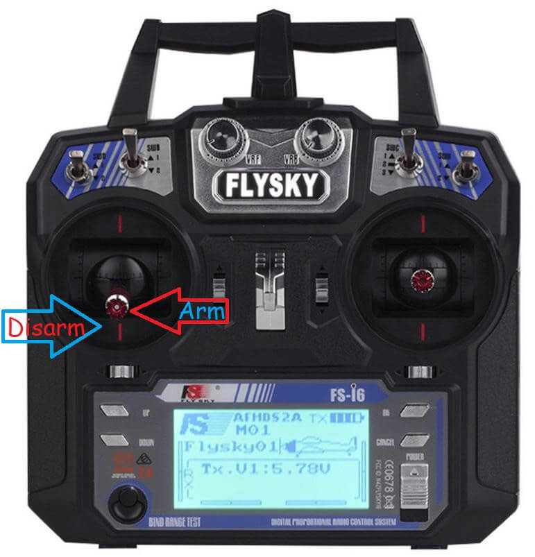
Сначала разместите дрон на ровной и открытой площадке. Затем выполните следующие шаги:
- Подключите аккумулятор дрона. Вы должны услышать упомянутые ранее звуки.
- Включите FlySky. Убедитесь, что батарея заряжена, и устройство чистое от грязи.
- Быстро нажмите стик рыскания влево, чтобы активировать дрон (специфично для этого дрона).
- Моторы дрона должны равномерно увеличивать обороты до 10% дросселя. Дрон не должен взлетать.
- Установите стик дросселя в центральное положение (50% мощности). Дрон должен взлететь и зависнуть на высоте 5 футов.
- Отпустите все управления. Дрон должен зависнуть стабильно и не улетать как пуля.
Заключение
Это был самый масштабный проект, который я когда-либо создавал, и это чудесно. Надеюсь, вам понравилось строить и летать на этом дроне вместе со мной! Увидимся в следующий раз!
Часто задаваемые вопросы
- Сколько времени занимает сборка дрона? — Сборка дрона может занять от нескольких часов до нескольких дней в зависимости от вашего опыта и доступности всех необходимых компонентов.
- Что делать, если дрон не стабилен в полёте? — Проверьте балансировку пропеллеров и моторов, убедитесь, что всё собрано правильно и все компоненты работают.
- Могу ли я использовать другие компоненты, отличные от указанных? — В идеале, используйте именно те компоненты, которые указаны, но если не получается, выбирайте максимально близкие по характеристикам аналоги.
- Как долго дрон может оставаться в воздухе на одной зарядке? — Время полёта дрона на одной зарядке зависит от ёмкости аккумулятора и конфигурации дрона, в среднем это может быть от 10 до 20 минут.
- Что делать, если у меня возникли проблемы с программированием? — Проверьте все подключения, следуйте инструкциям внимательно и, если проблемы не решаются, обратитесь за помощью в комментариях или на форумах.
Гизмо, Индия
As an Amazon Associate I earn from qualifying purchases.
If you love the idea of building your own quadcopter but haven’t got a clue how and where to start, you are definitely on the right page. We know how difficult and frustrating the research can be, so we decided to make a tutorial for building your own quadcopter using an Arduino board. We hope that you will find it useful.
And, to get you even more excited about your upcoming project, here is an Arduino quadcopter in action:
Building your own quadcopter from the ground up includes plenty of hours and hard work. Therefore, if patience isn’t your strong suit, and if you don’t possess the necessary programming skills, you can choose a quadcopter kit that contains the necessary parts and comes with instruction. This project doesn’t actually involve serious building, and is more of a “put all the parts together following the instructions” type of project. It is usually done in an hour or two, and right after, you are ready to hit the skies!
However, with those quadcopter kits, you will miss out on the long hours and sweat invested in building, and getting to understand the essence of your bird and how it ticks. Also, you will miss out on the overwhelming feeling of satisfaction when you take off with your handmade quad for the first time.
The entire process of building the quad is what hardcore drone hobbyists love. You simply get hooked by the feeling of being involved in the entire process, from the choosing of the parts, the designing of the circuits, to the programming of your Arduino flight controller board. But, we’re getting ahead of ourselves here, so let’s start from the beginning.
General “Quad Science”
As the name suggests, a quad drone is basically a flying vehicle with four electric motors and four propellers. When compared to other RC flying vehicles, the quad, as well as other multi-rotors, comes with the most stable platform, all thanks to its different design, and the direction and the difference between the four thrusts that it generates. This stability is why quads are perfect for aerial surveillance and filming. They come in all shapes and sizes. From the small ones that can fit in the palm of your hand, to the big ones that are capable of lifting serious filming equipment and gimbals. You would be surprised by just how much weight the bigger drones can carry!
Now, unlike the traditional helicopter, the quad relies on its four rotors to generate uplifting thrust by working together. Every single rotor lifts around a quarter of the overall weight, which allows us to use smaller and less expensive motors. You basically control the movement of the quad by changing the amount of power each motor delivers to its propellers.
The motors are positioned in every corner of an imaginary square. On one diagonal, you have two motors that rotate in a clockwise direction, while the remaining two, on the opposite diagonal, rotate counterclockwise. If this wasn’t the case, the quad would only spin around like a traditional helicopter when the tail rotor dies.

In order for the balance to be maintained, the quad relies on the data it gathers from internal sensors, and adjusts the power it sends to each motor so that the entire drone is leveled. To keep balanced all of the time, the quad uses an advanced control system, which usually makes the adjustments autonomously, and this is where your Arduino board and your programming come into play. This type of self-stabilization will make your drone quite accessible to fly, as you won’t have to constantly worry about losing control and damaging your quad.
Usually, each quad comes capable of performing four types of movement: Altitude, Roll, Yaw, and Pitch. Each of these movements is controlled by the amount of thrust each rotor produces. This is why you will need to program your remote control so that it knows how much power to give and to which rotor to give it.
Every quadcopter comes with a microcontroller board with sensors on it, in your case – the Arduino board. This board, together with the components you choose, controls the motors. It is up to you to choose how self-controlling you want your quad to be. You can use only the basic ones such as the gyro, or a bunch of other, more advanced sensors such as a barometer, or a GPS, or even a sonar so that your quad can be able to detect and avoid obstacles that are in its way.
Quads, as with all drones, are highly customizable, and you can truly build one that represents your interests. This is a major appeal of the DIY process to many enthusiasts. Whether you are interested in photography, video, drone racing, or just flying for fun, you’ll find that a quadcopter can offer something for you. Unmanned aerial vehicles are very adaptable and customizable, and we think you’ll enjoy customizing one that suits your preferences.
Components You Will Need For Your Quad
Every quad will have to include the elements listed below in order to fly. Here is a short summation of each of the various parts of a quad, and we will cover these in more detail as the article goes on:
- Frame– The “backbone” of the quadcopter. The frame is what keeps all the parts of the helicopter together. It has to be sturdy, but on the other hand, it also has to be light so that the motors and the batteries don’t struggle to keep it in the air.
- Motors– The thrust that allows the quadcopter to get airborne is provided by Brushless DC motors and each of them is separately controlled by an electronic speed controller or ESC.
- ESCs – Electronic Speed Controller is like a nerve that delivers the movement information from the brain (flight controller) to the arm or leg muscles (motors). It regulates how much power the motors get, which determines the speed and direction changes of the quad.
- Propellers – Depending on the type of a quad you build, you can use 9 to 10 or 11-inch props (for stable, aerial photography flights), or 5-inch racing props for less thrust but more speed.
- Battery – Depending on your setup maximum voltage level, you can choose from 2S, 3S, 4S, or even 5S batteries. But, for a standard for a quad that is planned to be used for aerial filming or photography (just an example), you will need a 11.4 V 3S battery. You could go with the 22.8 V 4S if you are building a racing quad and you want the motors to spin a lot faster.
- Arduino board –The choice of the specific model depends on the type of the quadcopter you want to build. Whether you are building for aerial photography, racing, freestyle, or more. We will talk about the right choice of board further down the article.
- IMU – A board that is basically (depending on your choice) a sum of various sensors that help your quad know where it is and how to level itself.
- RC Controller – The choice of the transmitter depends on the choice of the protocol you are going to use and the signal receiver that is onboard the drone.
These are the basic components of a drone. Read on for a more detailed description of each component:
Part #1 – Frame
Although it might be tempting to buy a preassembled frame kit, building the frame on your own can help you kick start your true DIY process. The Frame of your quadcopter has to possess strength, but it also has to be flexible enough to compensate for the vibrations the motors produce. It needs to have the following parts:
- Center Holding Plate – for mounting the electronics.
- Arms – there are four arms on a quad.
- Motor Brackets – you need four of them so that you can connect the motors on each arms end.
The frame can be made of aluminum, carbon fiber or wood but the material that is mostly used for the arms is aluminum. More precisely, the square hollow rails of the arms are made of aluminum. They are relatively lightweight, rigid and cheap. But, since they are not known as great compensators for the motor vibrations like carbon fiber ones are, they can confuse the sensors.

Carbon fiber offers much better absorption of the motor vibrations and is the most rigid one. But, it is also the most expensive one. Carbon fiber is the superior choice, but this very much depends on your personal budget.
Wood boards are also better for motor vibration absorbtion, but are quite fragile and can break easily in the event of a crash. You can also opt for a frame that is pre-made and only needs assembling, and you can find out more about those in our article about frame kits.
Check out our suggestions for the best-premade frames which you can use as a base for your project:
- LHI 220-RX FPV Quadcopter Frame (Carbon Fiber)
- Readytosky FPV Drone Frame (Carbon Fiber)
- iFlight XL5 V3 240mm FPV Frame Carbon Fiber
- Mallofusa 4-Axis HJ450 F450 RC QuadCopter Multirotor Airframe
- Usmile X style Carbon Fiber Drone Frame
- Readytosky S500 Quadcopter Frame with Carbon Fiber Landing Gear
Part #2 – Brushless Motors
These motors are almost the same thing as traditional DC motors, but the shaft on them doesn’t come with a brush, which is there to change the direction of the power that goes through the coils. When buying these motors, you need to check their technical data.

The most important ones are the “Kv-rating“, which tells you the number of RPMs the motor is capable of generating with a certain amount of electric power.
Also, you will need motors that rotate counter-clockwise, so that they counteract the props torque effect. For a better understanding of this topic, we suggest checking out our article about drone motors.
For the motors (or rotors), we would suggest these models:
- Emax RS2205 2600KV Brushless Motors
- Readytosky GT2205 2205 2300KV Brushless Motor
- HOBBYMATE 2204 QuadCopter Rotors Combo
- AOKFLY 4PCS RV1104 4200KV FPV Brushless Motor
Part #3 – Propellers
Propellers generate thrust, and each motor needs one in order for the quad to fly. Make sure that you buy the proper rotating pairs of propellers for clockwise and counterclockwise rotation. They can be bought in various pitches and diameters.
You have to choose the propellers according to the size of your frame, and once you have decided which propellers you will use, only then you can choose your motors. Propellers are standardized, and here are the most used ones for quads:
- 5 pitch, 8 diameter – Small quads
- 8 pitch, 9 diameter – Small quads
- 5 pitch, 10 diameter – Medium-sized quads
- 7 pitch, 10 diameter – Medium-sized quads
- 5 pitch, 12 diameter– Provide plenty of thrusts and are great for quads that are larger
Since aerodynamics is just more than confusing and difficult to understand if you are not an Engineer in Aerodynamics, we will explain a few important terms in a few words.

First, the larger the diameter and pitch are, the more thrust will the propeller produce. It will need more power, but the quadcopter will be capable of lifting more weight. For high RPM motors, you need smaller or mid-sized propellers. For low RPM motors, you need the larger propellers so that they can keep the quad in the air at lower speed.
Second, to achieve the perfect balance between the motors and propellers, you first need to decide what you will use the quad for. For example, if you want to build a stable and powerful enough quad to lift filming and photography equipment, you should use a motor with less RPM’s and more torque, and longer or higher pitched propellers.
If you want good performance propellers we recommend you to get any of these:
- BTG Quick Release Carbon Fiber Reinforced Propellers
- Myshine 9450 Self-tightening Propeller Props
- Performance 1245 Black Propellers MR Series
- USAQ Carbon Fiber Propellers (2) Pair
- Helistar Propellers 6 Pairs 4730F Colored Quick Release Folding Blades
Part #4 – ESC (Electronic Speed Controller)
The device that is in charge of controlling the speed of the motors is a cheap controller board, used only for motors. It comes with an input for a battery, and has a motor output with three phases, so you will need four of them for each motor.

When buying the proper ESC, you need to pay attention to the max level of the current that comes from the source. Choose a controller with 10A or higher.
Also, you need to check how programmable it is, meaning that you need to buy an ESC that will allow you to change the signal frequency range to the value you want.
When it comes to ESCs (Electronic Speed Controllers), we would suggest these models, which are great and stable:
- AKK 30A 4 IN 1 2-6S Brushless ESC BLHeli_S Electronic Speed Controller DShot150/300/600 Capable for Micro Racing Drones
- Original Airbot Omnibus F4 Nano Flight Controller
Part #5 – Battery
The most recommended power source for your quadcopter is the LiPo. It’s not heavy, and the current levels are ideal for what you need. NiMH is a cheaper, but also heavier, option.

LiPo batteries come as a single 3.7V cell or packed together as one (up to 10 cells which provide 37V).
The most popular version among the drone hobbyists is known as the 3SP1 battery, which comes with three cells and provides 11.1V.
Here’s a good one: Zippy Flightmax 5000mAh 3S1P 20C
Part #6 – IMU (Inertial Measurement Unit)
This unit is in charge of measuring the quad’s orientation, velocity, and the force of gravity. This allows the electronics to control the amount of power sent to motors, in order to adjust the motors’ speeds. The unit comes equipped with a 3-axis gyroscope, and a 3-axis accelerometer. This combination is known as the 6DOF IMU.
Here’s a good option for building a quad: KNACRO 6508 IMU MPU6050 MPU-6050 6DOF
The gyroscope is there to read the values of angular velocity, while the accelerometer is in charge of measuring acceleration and force, meaning that it can feel the downwards gravity. Since it comes with three-axis sensors, it can sense the orientation of the quad.
Part #7 – Flight Controller
You can either choose to use a controller board that’s only purpose is to control a quadcopter, or you can choose an Arduino UNO. This is a general purpose microcontroller that allows you to build your own flight controller by buying the parts you want to install, and assembling the controller on your own.

If you are interested in getting started with electronics and coding, the Arduino UNO is the best possible board you can use. It is the most reliable and robust platform, and it allows you to literally play with it any way you want.
It comes with:
- 14 digital input/output pins (6 of them can be used as outputs for PWM)
- 6 analog inputs
- a 16 MHz quartz crystal
- a USB connector
- a power jack
- an ICSP header
- a reset button
You can use the USB cable to connect it to a computer, a battery, or an AC/DC adapter to power it up.
The best thing about this board is that it allows you to mess with it and not worry about destroying it. The worst thing you can do to it is fry the chip, which luckily can be replaced with only a couple of dollars.
You can program the “UNO” with the Arduino Software. To get the details which will help you get started with your Arduino UNO Flight Controller, please go to the last section of the post.
Part #8 – RC Transmitter
The most common way of programming and controlling a quadcopter is by an RC transmitter. You can usually choose between two modes, Acrobatic or Stable.
For controlling the quad in Acrobatic mode, the Gyroscope is the only one which sends the values to processing. In this case, the controlling sticks are there only for controlling and setting the speed of rotation for the three axes, and if you let go of them, the values are not re-balanced automatically.

This comes in handy for those who want to perform aerial stunts, because tilting the drone a bit is possible, and after the release of the sticks, the quad keeps the position. It’s not a good mode for beginners because it is quite difficult to control your quad in this mode. Basically, the more skill you have at controlling the drone, the less help you will likely want with stability.
So when you’re a beginner drone user, use the second mode of control, because for determining the drone’s orientation, every single sensor works in this mode. The motor speeds will be controlled automatically, and the drone will be balanced on its own.
There are various available RC control systems nowadays, like Futaba, Spektrum, Turnigy, FlySky, and so on. Here are a few of our favorites:
- Futaba 10JH 10-Channel Heli T-FHSS Computer Radio System
- Spektrum DX8 Radio Transmitter
- Turnigy 9X 9Ch Transmitter w/ Module
- Flysky FS-i6X 10CH 2.4GHz AFHDS RC Transmitter w/ FS-iA6B Receiver
Wiring, Soldering, and Programming
This is the most complicated part of the entire building process. Soldering is a very specific technique, so be sure to do this process carefully. Make sure you know exactly what you need to do before you start each step. For this, you will need the following:
- Arduino UNO
- MPU-6050 Module
- Prototype Board
- Female and Male Headers
- 330-ohm Resistor and an LED
- Thin Gauge Wires
- HC-05 Bluetooth Module
Buy the Bluetooth module only if you want to be able to have an insight into the parameters and tune the quad through an app, as opposed to taking the laptop with you out on the field when testing.
Schematics
This is the main blueprint of your operation:

How to connect the ESCs:
- Signal Pin ESC 1 – D3
- Signal Pin ESC 3 – D9
- Signal Pin ESC 2 – D10
- Signal Pin ESC 4 – D11
How to connect the Bluetooth module:
- Tx – Rx
- Rx – Tx
How to connect the MPU-6050:
- SDA – A4
- SCL – A5
How to connect the LED indicator:
- LED Anode Leg – D8
How to connect the receiver:
- Throttle – 2
- Elerons – D4
- Ailerons – D5
- Rudder – D6
- AUX 1 – D7
You need the MPU-6050, the Bluetooth module, the receiver, and the ESCs, to be grounded. And, to do that, you need to connect the all GND pins to the Arduino GND Pin.
How to Solder Everything Together
Here’s the order which you should solder all your pieces together:
The first thing you need to do is to take the female headers and solder them to the prototype board. This will house your Arduino board.
Solder them right in the center so that there’s room for the rest of the headers for the MPU, Bluetooth module, Receiver, and the ESCs, and leave some space for some additional sensors you may decide to add in the future.
The next step is soldering the Receiver and ESCs male headers right from the Arduino female headers. How many male ESC header rows you will have, depends on how many motors your drone will have.
In our case, we are building a quadcopter, meaning there will be 4 rotors, and an ESC for each. That further means there will be 4 rows with each having 3 male headers.
The first header in the first row will be used for the Signal PID, the second for the 5V (though, this depends on your ESCs having a 5V pin or not, if not, you will leave these headers empty), and the third header will be for the GND.
When the ESCs are finished being soldered, you can move on to the Receiver headers’ soldering part. In most cases, a quad has 4 channels. These are Throttle, Pitch, Yaw, and Roll. The remaining free channel (the fifth one), is used for Flight mode changes (the Auxillary channel). This means that you will need to solder male Headers in 5 rows. All but one will have one header, while just one of those rows needs 3 headers in a row.
How to Wire Everything
You can see an example of the correct wiring below. As you can see in the picture, what we were just talking about is positioned left (The MPU soldered central) on the board, while the left (two female headers soldered bottom) on the board, is how we soldered and wired the Bluetooth module.
In our case, all the grounds were connected with the Arduino grounds. That includes all ESC grounds, Receiver ground (Throttle signal header completely on the right), and the Bluetooth module and MPU grounds.
Next, you need to follow the schematics and the connections we explained above. For example, the MPU ( SDA – A4, and SCL – A5), and for Bluetooth (TX – TX and RX – RX) of Arduino.
After that, just follow the connections as we wrote them: Signal pins of ESC1, ESC2… to D3, D10… of Arduino. Then the Receiver signal pins Pitch – D2, Roll – D4… and so on.
Furthermore, you need to connect the Long Lead of the LED (positive Terminal) to the Arduino D8 Pin, as well as add the 330-ohm resistor in between the Ground of Arduino and the LED Short lead (negative terminal).
The last thing to do is to provide a 5V power source connection. And, for that, you need to parallel connect the Black wire (ground of the battery) to the ground of all your components, and the Red wire to Arduino, MPU, and Bluetooth Module, 5V pins.
Now, the MPU 6050 needs to be soldered to male headers and to the ones you plan on using. After that, turn the board 180 degrees and connect all your components to the respective headers on the prototype board.
Here is how it should look when all the soldering and wiring is finished:

Power it up and your Arduino is ready for adding codes through a computer!
How to Program Your Arduino Flight Controller
An Arduino flight controller also requires some computer programming to get working. Now that we are done the building and the soldering, we can get into the coding aspect. This section contains a step-by-step guide of what you need to do to get your Arduino flight controller started.
First, you need to download the MultiWii 2.4. Then, when you extract it, you will get this:

Enter the MultiWii folder, and look for MultiWii icon and run it:

Use the Arduino IDE to find the “Arduino File” or Multiwii file with “.ino”. Any “CPP file” or “H file” are the support files for our Multiwii Code so don’t open those. Just use the Multiwii.ino file.

When you open the file, you will find many tabs such as Alarms.cpp, Alarms.h, EEPROM.cpp, EEPROM.h and many more. Find the “config.h”
Scroll down until you find ‘The type of multi-copter” and then by deleting the “//” you mark this as defined and running. Quad X because we are assuming that you are using the “X” rotor configuration on your quad.

Now scroll down and look for “Combined IMU Boards” and activate the type of Gyro+Acc Board you are using. In our case, we used the GY-521 so we activated that option.

If you decide to add other sensors such as a barometer or an Ultrasonic sensor, all you have to do is to “activate” them here and they will be running.
Next is the “Buzzer pin”:
There, you need to activate the Flight indicator options (the first 3 ones):
Now, you need to flash the code to your Arduino.
Unplug the Arduino board from the Flight controller and then connect it to your computer using USB. Once out of the FC and connected to your computer, you will find TOOLS and select the type of your Arduino board (in our case Arduino Nano).

Now find “Serial Port” and activate the COM Port that the Arduino Nano is connected to (in our case, COM3).
Finally, click on the arrow and upload the code, and wait for the code to be transferred.

When the upload is finished, unhook the Arduino from USB, insert it back to its place in the FC board, and connect a 5V battery so that the entire FC is powered up, and then wait until the LED on the Arduino is red. That means it has finished booting and that you can connect it to your computer again.
Now, find the Multiwii 2.4folder, then the MultiwiiConfig, and locate the folder that is compatible with your OS. In our case, it is the “application.windows64”.

Now start the MultiwiiConf application:

Once the user interface opens, you need to choose your Arduino’s COM port and click on Start like shown in the image below.

And, that’s it! You will immediately notice how you move the FC, the values for the Accelerometer and Gyroscope data are shown on the screen.The orientation of your FC is shown at the bottom.
In this interface, you can change the PID values and fine-tune your quad to match your personal preferences. You can also assign the flight modes to certain Auxillary switch positions in this interface.
All you have to do now is find a place for your Arduino FC on the frame and it is ready to hit the skies.
Wrap Up
Building a drone all on your own can be a complicated and arduous process. However, it is also guaranteed to come with its own sets of rewards and satisfactions. It is very easy to go to the store and buy a drone that is ready to fly, but people who build drones from scratch don’t do it for this reason. It is the feeling you get the very first time you fly a drone that is entirely of your creation. These aerial vehicles are quite a bit of fun to fly, but there’s a chance you might have even more fun before the flying even begins!
We are hoping that this article helped you and gave you a better insight to what each part of the quadcopter does. Now you should know how to select the right parts for your quadcopter. If you manage to build your own quadcopter and everything goes well, you can check out our other article about how to fly a quad to get more tips.
Additionally, here is a video series that shows how to put all the parts together and build an Arduino Quadcopter from scratch. If you are a visual learner, this should be a nice supplement to this article that you can reference if you are ever stuck in any stage of building your quadcopter:
YMFC-3D Part 1 — Hardware
YMFC-3D Part 2 — Connect RC Transmitter and Receiver
YMFC-3D Part 3 — How to Connect a Gyro
YMFC-3D Part 4 — Electronic Speed Controller (ESC)
YMFC-3D Part 5 – Quadcopter PID Controller and PID Tuning
YMFC-3D Part 6 — Flight Controller With Source Code
Feel free to leave a comment or give us some feedback on this post. Happy building!
Amazon and the Amazon logo are trademarks of Amazon.com, Inc, or its affiliates.