
- June 6, 2024
- GALU
Table of Contents
- CAUTION:
- Tools Required
- Products Configurations:
- Technical Specifications
- Power Supply Mode Connection Guide
- Installation Steps
- Solar Power Mode Connection
- Installation Steps
- Control board wiring diagram:
- Technical Parameters:
- Remote control
- Read User Manual Online (PDF format)
- Download This Manual (PDF format)
GALU Linear Actuator 24V Swing Gate Opener User Manual

CAUTION:
- This product must be installed by well-trained skilled personnel in compliance with the safety regulations the field of residential and commercial swing gate opener devices. Unqualified personnel may damage the instruments And cause harm to the public.
- Electric Power must be disconnected prior to installation, or performing any maintenance.
- Please read the manual carefully before installation. Incorrect installation or misuse of product may cause seriously damage to users and property.
- If the electric cable is damaged or broken, it must be replaced by a whole and properly insulated wires, to avoid electric shock or any hazardous environments.
- Keep the wireless transmitters out of children reach.
- Do not allow children or other individuals to stand by the path of the motor arms or the path of the gates while in operation.
- Do not use the remote wireless transmitters when the gates are out of sight.
- Do not install the products in corrosive, inflammable, and/or explosive environments.
- Avoid installing the motor arm where the override manual release key is exposed to the public
Tools Required

Products Configurations:
Products and accessories list


Configuration of Swing Gate Opener PKM-C01 Dimensions are in mm

Nomenclature of Swing Gate Motor

Open the gate manually: Release by spanner then lift it

- Item 1: Gate
- Item 2: Manually spanner
- Item 3: Release by spanner then lift it and separate the motor from gate
Swing Gate Opener Features & Options:
- In case of power failure: Use the manually spanner to release to separate the motor and gate, open or close the gate manually.
- When Gate is Obstructed: Gate stops .
- Optional: The Gate Opener Controller can be connected to a solar system, a flash light warning, a photocell, back up battery, keypad and other access control devices.
- Speed Control: Gate opening and closing speed can be adjusted.
- Gentle Start: The Gate Opener is equipped with a soft start function.
- Auto Close: The Gate Opener System is equipped with Auto close function with adjustable closing time delay.
- Single or Dual Gate: Either Single or Dual Swing Gate can be opened.
- Multiple Remote Transmitters: The Controller can easily accommodate several unique extra remotes to control the swing gate opener
- Battery Back Up: DC 24V back up battery can be incorporated
- Optional Devices: DC 24V Gate Lock, photocell ,keypad , photocell, push button, large size or small size control box.
- The Gate Opener can be configured to allow smooth noiseless operation.
- The Gate Opener can be configured to enable open condition as default, or close condition as default depending on the placement of the provided hardware bracket brackets.
Technical Specifications
Motor voltage: 24VDC 40W| Input
power:220VAC±10%/120VAC±10%
—|—
Rotational speed : 200 RPM| Arm’s extended speed
: 1.6 cm/s
Arm’s max travel : 300 mm| Continue running
time: 5 minutes
Max single-leaf length : 2.5meters| Max single-leaf
weight : 200 KG
Environment Temperature : -45°C ~ +50°C| Protection
Class : IP55
Max gate open angle: 110 degree| Dual Swing
Gate Gross weight : 15KG
Preparing The Installation Site:

Item Nomenclature
- Wireless Transmitter
- Rubber Stoppe
- Swing Gate Opener Motor
- Control Box
- Photocell Electric Sensor
- Flash Light Alarm ( Optional )
Rear Bracket Installation Alternatives to Gate Posts

-
Construction Drill and Bolts, Figure 5 right:
a. Drill 4 Holes of 8mm Diameter
b. Insert the 4 Provided Concrete Bolts and Tighten Properly (Do not over
tighten as you may strip the bolt out of the concrete or the brick)
c. Place the Motor Connecting Bracket and Tighten with the Provided
Screws -
Construction Drill and Weld, Figure 5 middle:
a. Drill 4 Holes of 8mm Diameter
b. Locate the 4 Slotted Holes Post Bracket above the Drilled Holes
c. Weld the Motor Bracket to the Post Bracket -
Precast U Bolts, Figure 5 left:
a. Locate the 4 Slotted Holes of the Post Bracket above the End of U Bolts
b. Apply the Appropriate Screws
c. Place the Motor Connecting Bracket and Tighten with the Provided
Screws
-
Adjusting different angles of Rear Bracket Fixed Plate to fit different Installing condition.


Considerations

Figure 7 left, Power Cable And Rain
Drainage Aperture Placed Correctly
-
Post Rear Fixed Bracket
-
Lock in
Figure 7 right, Power Cable And Rain
Drainage Aperture Placed Incorrectly
-
Rain Drainage Aperture
-
Power Cable
Notice: Incorrect Installation, Figure 7 right: Cable must not be
installed above the motor arm. It may pinch and strip the cable and causes
electric shock. Follow correct installation as shown in Figure 7left.
Installation of Extended or Retracted End Motor Arms to Gates:

- A. Drill 2 Holes of 10.2mm Diameter With Space 68mm Between 2 Holes
- B. Locate the 2 Slotted Holes Gate Bracket above the Drilled Holes
- C. Place the End Motor Bracket to the Gate Bracket using the Appropriate Bolts and Tighten Properly(Please note these bolts used to fixed front bracket to the gate are not provided due to the thickness of each gate is different)
- D. Insert the Lock Pin and Clamping Washers
Brackets Height :

Ensure that the Post bracket height is in the same exact level with the gate
bracket height. Failing to ensure accurate common heights will cause the motor
arm to bend leading to failure. Also, the force to push or pull the gate will
be reduced causing the motor to open or close the gates with difficulty or may
not operate successfully at all. Severe different in height will damage the
motor and the motor arm.
Configuration of Normally Closed Gate Opener System
Installation size(you can adjustment the gate degree according to these
numbers)

Power Supply Mode Connection Guide
- Type 1: AC Power Mode Connection
Tips: Our gate opener system support powered by AC 110V or solar and
battery, please select the connection mode according to actual needs.

Installation Steps
-
Step l: Drill holes in the control box to pass the wires through.
-
Step 2: Connect the cable of master arm to the control board. (Note:2pcs 8m*2 cord extension cable are included in the package, please connect the extension wire refer to actual need.)
-
Step 3: Connect batteries to the control board (Note:2 pack batteries are included in some models, please refer to the actual package. )
-
Step 4: Connect the Infrared Beam Sensor receiver
-
Step 5: Connect the Infrared Beam Sensor transmitter (Note: The port close to the indicator light is ” – “, and the other end is “+”. )
-
Step 6: Connect the extension cord at the control box end to the wire plug (not included) and connect to the commercial power, the AC power mode connection finished


Solar Power Mode Connection

Installation Steps
-
Steps 1: Drill holes in the control box to pass the wires through.
(Note: If connected to the solar mode, the extension cable dedicated to
commercial power can be pulled back into the control box so that the solar
panel cable can enter to wiring through this hole)
-
Step2: Connect the cable of master arm to the control board. (Note:2pcs 8m*2 cord extension cable are included in the package, please connect the extension wire refer to actual need.)
-
Step3: Connect batteries to the control board (Note:2 pack batteries are included in some models, please refer to the actual package. )
-
Step4: Connect the Infrared Beam Sensor receiver (Note: Solar panel included in some models, please refer to the actual package.)
-
Step5: Connect the Infrared Beam Sensor transmitter (Note: The port close to the indicator light is ” – “, and the other end is “+”. )


Control board wiring diagram:
Technical Parameters:
- Control Panel Voltage: AC24V, available for 24 V back up battery.
- Applicable Range: Suitable for double arms swing gate opener.
- Encoder For transmitter: Our own customized rolling code.
- Support remote control: Can memorize 120PCS transmitters at most
- Motor character: 24V DC motor x2

- 2 SIDE terminal is used for connecting any external device that operates double gate
- COM terminal is COMMON used for connecting the “ground” of external devices
- 1 SIDE terminal is used for connecting any external device that operates single gate
- Swipe Card terminal is used for connecting any external devices that will operate to open the gate
- COM terminal is COMMON used for connecting the “ground” of external devices
- Infrared terminal is used for connecting photo electric sensor
- 12V DC output is used for connecting photo electric sensor (Continuous output current <=200mA)
- 24V battery output is used for connecting the back up battery +
- 24V battery output is used for connecting the back up battery –
- 24V DC output is used for connecting external device. (such as photo electric sensor, max current output 1A)
- GND is used for connecting the “ground” of external devices
- 24V DC lamp output is used for connecting flash light +.
- 24V DC lamp output is used for connecting flash light -.
- 24V DC lock output—the NF terminal which used for connecting the electric lock
- COM is COMMON used for connecting the “ground” of lock
- 24V DC lock output—the NA terminal which used for connecting the magnetic lock
- 24V DC alarm output
- 24V DC alarm output
- and 20. Motor1 terminal is used for connecting the motor 1 installed on the gate that opens later and close first. This terminal connect 1st red wire (counted from your left hand side to right hand side)
- and 22. Motor2 Delay terminal is used for connecting the motor 2 installed on the gate that opens first and close later. This terminal connect 1st blue wire (counted from your left hand side to right hand side). NOTE! If for single gate, the gate motor just can connect the Motor2 Delay terminal.
- AC24V input is used for connecting the transformer
- AC24V input is used for connecting the transformer
- digital display is used for showing you the setting data
- INC+ is used for figure increase when setting the data
- FUN is used for store the data
Remote control
Button “1” depressed to operate single gate; button “2” depressed to operate
double gate; button “3” depressed for alarm output
Program new remote control:
-
First step:
Press the LEARN button on the control board for about 1 second, the indicator
LED would turn off, then now means have already enter learning -
Second step:
Press any button of the new remote control for about 2 second, then digital
display would show the remote number while indicator LED on board starts flash
four times with one buzzer sound then now means the learning successfully.
Note! After you press LEARN button, if not receive the new remote signal
within 5s, indicator LED would turn on and exit learning.
Remove remote control:
Press and hold the LEARN button for about 5 second, if with one buzzer sound
and indicator LED light on, then now means remove remote successfully.
Setting of the control board:
After power on, digital display will self-check from 00-99 with buzzer sound.
If indicator LED light on, buzzer stop sound, it means the system is normal.
Basic operation method:
After power on, digital display will self-check from 00-99 with buzzer sound.
If indicator LED light on, buzzer stop sound, it means the system is normal.
Basic operation method:
Press and hold the [ FUN] button until the digital display shows PO. Now you
enter the menu setting. You could through adjust the [INC+] [DEC-] to increase
or decrease the serial number or numerical value. After data adjust well then
press [ FUN] to store the data. With one sound of buzzer, the store
successfully. After store the data, the digital display would still on the
menu number you just set, if you need to enter next menu setting, please press
[INC+] or [DEC-] to choose and confirm with [FUN] to enter the menu number you
want to set. Such as after you store the P0 value and press [FUN] to store it,
then now the digital display would still show the number P0, and if you want
go further to adjust P1, please press one [INC+], then digital display show
P1, later press [FUN] to enter the P1 setting. And if you not need to enter
next menu setting, you could press [LEARN] button to exit the menu setting
-
To set the soft start time:
When digital display indicate P0, the gate opener is on the soft start time
setting. The soft start time adjustable from 0-6s, 0s means close the soft
start time, max soft start time 6s. Each time you press and release the [INC+]
button, the figure increase by 1; each time you press and release the [DEC-]
button, the figure decrease by 1. Press the [FUN] button to store the data
when the soft start time chosen, then the soft start time setting finished
(Factory set 2s). -
To set the level of stall force:
-
When digital display indicate P1, the gate opener is on Motor 1 low speed running stall force adjustment. There is 0-20 levels for optional, each time you press and release the [INC+] button, the figure increase by 1; each time you press and release the [DEC-] button, the figure decrease by 1. Press the [FUN] button to store the data when the stall force level chosen, then the stall force of Motor 1 low speed running stall force adjustment finished. (factory set 6 level)
-
When digital display indicate P2, the gate opener is on Motor 1 high speed running stall force adjustment. There is 0-20 levels for optional. Each time you press and release the [INC+] button, the figure increase by 1; each time you press and release the [DEC-] button, the figure decrease by 1. Press the [FUN] button to store the data when the stall force level chosen, then the stall force of Motor 1 high speed running stall force adjustment finished. (factory set 10 level)
-
When digital display indicate P3, the gate opener is on Motor 2 low speed running stall force adjustment. There is 0-20 levels for optional. Each time you press and release the [INC+] button, the figure increase by 1; each time you press and release the [DEC-] button, the figure decrease by 1. Press the [FUN] button to store the data when the stall force level chosen, then the stall force of Motor 2 low speed running stall force adjustment finished. (factory set 6 level)
-
When digital display indicate P4, the gate opener is on Motor 2 high speed running stall force adjustment. There is 0-20 levels for optional. Each time you press and release the [INC+] button, the figure increase by 1; each time you press and release the [DEC-] button, the figure decrease by 1. Press the [FUN] button to store the data when the stall force level chosen, then the stall force of Motor 2 high speed running stall force adjustment finished. (factory set 10 level)
-
To set the high speed running time:
When digital display indicate P5, the gate opener is on high speed running
time setting. There is 0-33s for optional. 0s means without high speed
running, gate opener would keep running in slow speed. Max high speed running
time 33s. Each time you press and release the [INC+] button, the figure
increase by 1; each time you press and release the [DEC-] button, the figure
decrease by 1. Press the [FUN] button to store the data when the high speed
running time chosen, then the high speed running time setting finished.
(factory set 5s) -
To set the auto close time after swipe card:
When digital display indicate P6, the gate opener is on auto close time
setting ( NOTE! this auto close time just means the auto close function which
realize through external device-).
There is 0-99s for optional. 0 means the gate opener would not auto close
after swipe card.
Max auto close time after swipe card 99s. Each time you press and release the
[INC+] button, the figure increase by 1; each time you press and release the
[DEC-] button, the figure decrease by 1. Press the [FUN] button to store the
data when the auto close time after swipe card chosen, then the auto close
time after swipe card finished. (factory set 10s) -
To set the interval time:
-
When digital display indicate P7, the gate opener is on open interval time setting. There is 0-10s for optional. 0s means double gates open simultaneously. “1” means the Motor 1 start to open 1 second before Motor 2 start to open. Max open interval time 10s. Each time you press and release the [INC+] button, the figure increase by 1; each time you press and release the [DEC-] button, the figure decrease by 1. Press the [FUN] button to store the data when the open interval time chosen, then the open interval time setting finished. (factory set 0s)
-
When digital display indicate P8, the gate opener is on close interval time setting. There is 0-10s for optional. 0s mean double gates close simultaneously. “1” means the Motor 2 start to close 1 second before Motor 1 start to close. Max close interval time 10s. Each time you press and release the [INC+] button, the figure increase by 1; each time you press and release the [DEC-] button, the figure decrease by 1. Press the [FUN] button to store the data when the close interval time chosen, then the close interval time setting finished. (factory set 0s)
-
To set auto close time:
When digital display indicate P9, the gate opener is on auto close time
setting. There is 0-99s for optional. 0s mean the gate opener would not auto
close. Max auto close time is 99s. Each time you press and release the [INC+]
button, the figure increase by 1; each time you press and release the [DEC-]
button, the figure decrease by 1. Press the [FUN] button to store the data
when the auto close time chosen, then the auto close time setting finished.
(factory set 0) -
To set lamp/alarm output control:
When digital display indicate PA, the gate opener is on lamp/alarm output
control setting.
There is 0-3 for optional. “0” means the alarm on monostabillity model and the
lamp without voltage output after the gate total close 30s, other time with
voltage output. “1” means the alarm on monostabillity model and the lamp would
only flash when gate running. “2” means the alarm on bistabillity model and
the lamp without voltage output after the gate total close 30s, other time
with voltage output. “3” means the alarm on bistabillity model and the lamp
would only flash when gate running. Each time you press and release the [INC+]
button, the figure increase by 1; each time you press and release the [DEC-]
button, the figure decrease by 1. Press the [FUN] button to store the data
when the auto close time chosen, then the lamp/alarm output control setting
finished. (factory set 0) -
To set lock time:
When digital display indicate Pb, the gate opener is on lock time control
setting. The lock control time means the time we could control the lock. There
is 0-2 for optional. “0” means the lock control time is 15s, “1” means the
lock control time is 1.5s, “2” means the lock control time is 2s .Each time
you press and release the [INC+] button, the figure increase by
1; each time you press and release the [DEC-] button, the figure decrease by -
Press the [FUN] button to store the data when the lock control time chosen,
then the lock time setting finished. (factory set 0)
Note: The gate motor will open delay 0.5s to help unlock the electric lock -
To choose single/double gate open:
When digital display indicate PC, the gate opener is on single/double gate
open setting. There is 0-3 for optional. “0” means the gate could not open by
remote, “1” means just can open one single gate, “2” means can just open two
leaf gate, “3” means can open one single gate as well as two leaf gate. Each
time you press and release the [INC+] button, the figure increase by 1; each
time you press and release the [DEC-] button, the figure decrease by 1. Press
the [FUN] button to store the data when the single/double gate open chosen,
then the remote button setting finished. (factory set 3)
To choose photocell work in NC or NO
When digital display indicate Pd, you could choose the photocell work in NO or
NC. Value 00 means work in NO, value 01 means work in NC.
To choose Single /Dual motor control gate
When digital display indicate PE, you could choose control board work for
single motor or dual motor.
When set value 0, The control board work for dual motor .(Factory setting)
When set value 1, The control board only work for single motor -
To reset:
When digital display indicate Po, the gate opener is on rest setting. After
enter Po setting, press the [ FUN] to store and then now the reset
successfully
Read User Manual Online (PDF format)
Read User Manual Online (PDF format) >>
Download This Manual (PDF format)
Download this manual >>

Attention
The manual should be read cover
to cover once prior to beginning installation
CAUTION:
- This product must be installed by well-trained skilled personnel in compliance with the safety regulations the field of residential and commercial swing gate opener devices. Unqualified personnel may damage the instruments And cause harm to the public.
- Electric Power must be disconnected prior to installation, or performing any maintenance.
- Please read the manual carefully before installation. Incorrect installation or misuse of product may cause seriously damage to users and property.
- If the electric cable is damaged or broken, it must be replaced by a whole and properly insulated wires, to avoid electric shock or any hazardous environments.
- Keep the wireless transmitters out of children reach.
- Do not allow children or other individuals to stand by the path of the motor arms or the path of the gates while in operation.
- Do not use the remote wireless transmitters when the gates are out of sight.
- Do not install the products in corrosive, inflammable, and/or explosive environments.
- Avoid installing the motor arm where the override manual release key is exposed to the public.
Tools Required

I. Configuration of Swing Gate Opener PKM-C01 Dimensions are in mm

Figure 1
Nomenclature of Swing Gate Motor

Figure 2
Item 1: Post Rear Fixed Bracket
Item 2: Gate Front Fixed Bracket
Item 3: 300mm Extended Arm
Item 4: Motor Box
Item 5: Power Cable
Open the gate manually: Release by spanner then lift it.

Figure 3
Item 1: Gate
Item 2: Manually spanner
Item 3: Release by spanner then lift it and separate the motor from gate
II. Swing Gate Opener Features & Options:
- In case of power failure: Use the manually spanner to release to separate the motor and gate, open or close the gate manually.
- When Gate is Obstructed: Gate stops .
- Optional: The Gate Opener Controller can be connected to a solar system, a flashlight warning, a photocell, back up battery, keypad and other access control devices.
- Speed Control: Gate opening and closing speed can be adjusted.
- Gentle Start: The Gate Opener is equipped with a soft start function.
- Auto Close: The Gate Opener System is equipped with Auto close function with adjustable closing time delay.
- Single or Dual Gate: Either Single or Dual Swing Gate can be opened.
- Multiple Remote Transmitters: The Controller can easily accommodate several unique extra remotes to control the swing gate opener
- Battery Back Up: DC 24V back up battery can be incorporated
- Optional Devices: DC 24V Gate Lock, photocell ,keypad , photocell, push button, large size or small size control box.
- The Gate Opener can be configured to allow smooth noiseless operation.
- The Gate Opener can be configured to enable open condition as default, or close condition as default depending on the placement of the provided hardware bracket brackets.
III. Technical Specifications
|
Motor voltage: 12VDC 40W |
Input power:220VAC±10%/120VAC±10% |
|
Rotational speed:200 RPM |
Arm’s extended speed:1.6 cm/s |
|
Arm’s max travel:300 mm |
Continue running time: 5 minutes |
|
Max single-leaf length: 1.5meters |
Max single-leaf weight:150 KG |
|
Environment Temperature:-45°C ~ +50°C |
Protection Class:IP55 |
|
Max gate open angle: 110 degree |
Dual Swing Gate Gross weight : 13KG |
IV. Preparing The Installation Site:

Figure 4
Item Nomenclature
- Wireless Transmitter 4. Control Box
- Rubber Stopper 5. Photocell Electric Sensor
- Swing Gate Opener Motor 6. Flash Light Alarm ( Optional )
V. Rear Bracket Installation Alternatives to Gate Posts

Figure 5
1. Construction Drill and Bolts, Figure 5 right:
a. Drill 4 Holes of 8mm Diameter
b. Insert the 4 Provided Concrete Bolts and Tighten Properly (Do not over tighten as you may strip the bolt out of the concrete or the brick)
c. Place the Motor Connecting Bracket and Tighten with the Provided Screws
2. Construction Drill and Weld, Figure 5 middle:
a. Drill 4 Holes of 8mm Diameter
b. Locate the 4 Slotted Holes Post Bracket above the Drilled Holes
c. Weld the Motor Bracket to the Post Bracket
3. Precast U Bolts, Figure 5 left:
a. Locate the 4 Slotted Holes of the Post Bracket above the End of U Bolts
b. Apply the Appropriate Screws
c. Place the Motor Connecting Bracket and Tighten with the Provided Screws
4. Adjusting different angles of Rear Bracket Fixed Plate to fit different
Installing condition.

Figure 6

Figure 7
Figure 7 left, Power Cable And Rain Figure 7 right, Power Cable And Rain
Drainage Aperture Placed Correctly Drainage Aperture Placed Incorrectly
1 Post Rear Fixed Bracket 3 Rain Drainage Aperture
2 Lock in 4 Power Cable
Notice: Incorrect Installation, Figure 7 right:
Cable must not be installed above the motor arm. It may pinch and strip the cable and causes electric shock. Follow correct installation as shown in Figure 7left.
VII. Installation of Extended or Retracted End Motor Arms to Gates:

Figure 8
A. Drill 2 Holes of 10.2mm Diameter With Space 68mm Between 2 Holes
B. Locate the 2 Slotted Holes Gate Bracket above the Drilled Holes
C. Place the End Motor Bracket to the Gate Bracket using the Appropriate Bolts and Tighten Properly(Please note these bolts used to fixed front bracket to the gate are not provided due to the thickness of each gate is different)
D. Insert the Lock Pin and Clamping Washers
VIII. Brackets Height :

Figure 9
gate bracket height. Failing to ensure accurate common heights will cause the motor arm to bend leading to failure. Also, the force to push or pull the gate will be reduced causing the motor to open or close the gates with difficulty or may not operate successfully at all. Severe different in height will damage the motor and the motor arm.
Configuration of Normally Closed Gate Opener System
Installation size(you can adjust the gate degree according to these numbers)

Figure 10
Control board wiring diagram:
Technical Parameters:
- Control Panel Voltage: AC24V, available for 24 V back up battery.
- Applicable Range: Suitable for double arms swing gate opener.
- Encoder For transmitter: customized rolling code.
- Support remote control: Can memorize 50PCS transmitters at most
- Motor character: 24V DC motor x2

- E1 terminal is used for connecting any external device that operates single gate (cycle control the MAIN motor 2 open-stop-close-stop)
- COM terminal is COMMON used for connecting the “ground” of external devices
- E2 terminal is used for connecting any external device that operates double gates (cycle control open-stop-cloe-stop)
- IR is used for connecting photo electric sensor
- COM terminal is COMMON used for connecting the “ground” of external devices
- LAMP — terminal is used for connect lamp — .
- LAMP + terminal is used for connect lamp + .
- LOCK — terminal is used for connect mechnical lock — .
- LOCK + terminal is used for connect mechnical lock +.
NOTE: when gate trigger open signal, then lock output, after lock working 0.5s then gate start working, after more 4.5s, then lock stop output (the complete lock output time is 5s)
- 12V+ terminal is 12V power positive pole output, used for connecting an external device (max output 200mA)
- 12V- terminal is 12V power negative pole output, used for connecting an external device (max output 200mA)
- and 13. Motor1 terminal is used for connecting the motor 1 installed on the gate that opens later and closes first. This terminal connects 1st red wire (counted from your left-hand side to right-hand side)
- and 15. Motor2 Delay terminal is used for connecting the motor 2 installed on the gate that opens first and closes later. This terminal connects 1st blue wire (counted from your left-hand side to right-hand side). NOTE! If for a single gate, the gate motor just can connect the Motor2 Delay terminal.
- Power terminal input is used for connecting the transformer
- Power terminal input is used for connecting the transformer
- 24V battery output is used for connecting the backup battery —
- 24V battery output is used for connecting the backup battery +
Remote control
Button “1” depressed to operate MOTOR 2 single gate; button “2” depressed to operate MOTOR 2 single gate; button “3” depressed to operate double gate; button “4” depressed for alarm output
Program new remote control:
First step:
Press the LEARN button on the control board for about 1 second, the indicator LED would light on then now means have already entered learning
Second step:
Press any button of the new remote control for about 2 seconds, the indicator LED on board starts fast flash 2 times then now means the learning successfully.
Note! After you press LEARN button, if not receive the new remote signal within 8s, indicator LED would turn on and exit learning.
The remote that already learned can not code learning again.
Remove remote control:
Press and hold the LEARN button for about 8 seconds, if indicator LED light on, then now means remove remote successfully.
3. The setting of the control board:
3.1 Travel learning function:
When gate in fully open condition, press LEARN button 5 times continuous, indicator LED light on, then the motor will automatic to open and close one cycle. If indicator LED turns off then it means travel learning successfully. The system will automatic to allocate the high speed/ low speed running time.
3.2 Program setting:
3.2.1
For the sensitivity of meet resistance, there is a three-degree jumper for option, it can through adjust the jumper to chooseHeavy: it means used for heavy weight gateMedium: it means used for medium weight gateLight: it means used for the lightweight gate
3.2.2 Dip switch setting:
A. Dip 1 OFF and Dip 2 OFF : it means close the auto close function
Dip 1 ON and Dip 2 OFF: it means after full open gate 3s, gate will auto close; Dip 1 OFF and Dip 2 ON: it means after full open gate 10s, gate will auto close; Dip 1 ON and Dip 2 ON: it means after full open gate 30s, gate will auto close.
B. Dip 3 OFF: it means gate open and gate close delay 3s;
Dip 3 ON: it means close open/close gate delay, working at the same time.
C. Dip 4 OFF: it means when gate motor working, then lamp light on; when gate motor stop, then lamp turn off.
Dip 4 ON: it means when gate motor working, then lamp light on; after gate stop working 30s, then lamp turns off.
Описание Товара
описание продукта

ФУНКЦИИ
* Технические характеристики сошника с распашным клапаном
* способ движения: Тип поршня с винтовым приводом
* рабочее напряжение: 24 в пост. Тока
* используйте ширину одиночного затвора до 3,5 М.
* используйте вес с одним затвором до 300 КГ
* водонепроницаемый дизайн IP55
* регулируемое усилие
* Регулируемая задержка по времени
* Ручное освобождение
* Панель управления на базе микропроцессора
* Защита рабочего времени
* доступно для подключения фотоэлемента, контурного детектора, устройства считывания карт памяти, резервного аккумулятора и т.д.
Преимущество оператора с распашного борта:
1. Панель управления может подключать проблесковый маячок, фотоэлемент, резервную батарею, солнечную систему, клавиатуру и т. д.
2. Управление одним или одним двигателем с лепестками со смазкой является дополнительным оборудованием.
3. Может регулировать время открытия и закрытия дверцы.
Может быть поден входной сигнал от резервного аккумулятора 4,24 в пост. Тока. (используется большой контроллер, стандартный контроллер имеет малый размер.)
5.можно регулировать работу на высокой скорости.
6. Установка дополнительного пульта ДУ очень просто.
7: Работа с WiFi-устройством для управления воротами в приложении Mobile Phone
2 усиленный двигатель , предварительно смонтированы с двигателем кабели
2 гаечных ключа с ручным переключателем
2 пульта ДУ
1 панель управления
2 x монтажный кронштейн стойки
2 x монтажный кронштейн затвора
1 резиновый ограничитель заслонки
1 инструкция по эксплуатации
1. Напряжение панели управления: 24 в перем. Тока, доступно для резервной батареи 24 В.
2. Диапазон применения: Подходит для
сошник с двумя рычагами и поворотным затвором.
3. Кодовый датчик для передатчика: Собственный настраиваемый код качения.
4. Поддержка пульта ДУ: CAN
Запомните, что в памяти не более 5 передатчиков 120PCS. Символ двигателя: 24 в пост. Тока двигатель x2
Профиль компании
Компания Giant Alarm System CO.,LTD была основана в 2003 году. Наши основные продукты: Беспроводной радиочастотный пульт дистанционного управления, приемник, интеллектуальный открывающий механизм затвора, раздвижной сошник, автоматический барьер стрелы, все виды интеллектуальных плат управления для открывателя ворот и другие принадлежности автоматической системы машины. Как высокотехнологичная компания, занимающаяся производством и торговлей, наша компания охватывает все сферы деятельности: От НИОКР, производства, продаж до обслуживания. Наши основные награды: Национальный высокотехнологичный предприятие, известный бренд Фудзиана, инновационное пилотное предприятие Фудзиана, высокотехнологичное предприятие Фудзиана. Компания Giant занимает площадь 14000 квадратных метров, насчитывающую более 100 сотрудников, и имеет более 10000 мастерских.
JUJIANG PKM-C026-400-1 Dual Swing Gate Opener

Product Information
Specifications
- Input Power: 24V DC
- Motor Voltage: 24V DC
- Max Single-Leaf Weight: 350KG (770lbs)
Frequently Asked Questions
- Q: Can this gate opener be used on pedestrian gates?
- A: No, the gate opener is intended for use with class I vehicular swing gates and is not suitable for pedestrian gates. Pedestrians should have separate access.
Thank you for purchasing this product
Please read and follow all warnings, precautions and instructions before installation and using
Periodic checks of the opener are required to ensure safe operation
Keep the manual for future reference
Safety Installation Information
- READ and FOLLOW all instructions.
- The gate opener is intended for use with class I vehicular swing gates. Class I denotes vehicular gate opener (or system) dwellings, or a garage or parking area associated therewith. Install the gate opener only when the opener is appropriate for the construction and the usage class of the gate.
- Gate opening system designers, installers and users must take into account the possible hazards associated with each individual application. Improperly designed, installed or maintained systems can create risks for the user as well as the bystander. Gate system design and installation must reduce public exposure to potential hazards. All exposed pinch points must be eliminated or guarded.
- A gate opener can create high levels of force during normal operation. Therefore, safety features must be incorporated into every installation. Specific safety features include safety sensors.
- The gate must be properly installed and work freely in both directions prior to the installation of the gate opener.
- The gate must be installed in a location so that enough clearance is provided between the gate and adjacent structure when opening and closing to reduce the risk of entrapment. Swinging gates shall not open into public access areas.

- The opener is intended for use only on gates used for vehicles. Pedestrians must be supplied with a separate access opening. The pedestrian access opening shall be designed to promote pedestrian usage. The pedestrian access shall be located such that persons will not come in contact with the moving vehicular gate.
- Pedestrians should never cross the pathway of a moving gate. The gate opener is not acceptable for use on any pedestrian gate. Pedestrians must be supplied with separate pedestrian access.
- For an installation utilizing non-contact sensors, see the product manual on the placement of non-contact sensors (safety sensors) for each type of application.
- Care shall be exercised to reduce the risk of nuisance tripping, such as when a vehicle trips the safety sensor while the gate is still moving.
- One or more non-contact sensors (safety sensors) shall be located where the risk of entrapment of obstruction exists, such as the perimeter reachable by a moving gate or barrier.

- Never mount any device that operates the gate opener where the user can reach over, under, around or through the gate to operate the controls. Controls are to be placed at least 6’ (1.8m) from any part of the moving gate.
- Controls intended to be used to reset an operator after 2 sequential activations of the entrapment protection device or devices must be located in the line of sight of the gate, or easily accessible controls shall have a security feature to prevent unauthorized use. Never allow anyone to hang pon or ride the gate during the entire travel of the gate.

- Each gate opener is provided with two safety warning placards. The placards are to be installed on the front and back of the gate where they are plainly visible. The placards may be mounted using cable ties through the four holes provided on each placard. All warning signs are placards must be installed where visible in the area of the gate.
- To AVOID damaging gas, power, or other underground utility lines, contact underground utility locating companies BEFORE digging.


Swing Gate Opener Part List

Optional Accessories Parts List

Tools Required

Technical Specification
| Specifications | |
| Input power | 24V DC |
| Motor voltage | 24V DC |
| Power | 60W |
| Actuator speed | 2.4 cm/s |
| Max. Actuator travel | 400mm |
| Max single-leaf weight | 400KG |
| Max single-leaf length | 1.2~5 meters |
| Ambient Temperature | -22°C ~ +55°C |
| Protection class | IP55 |
| Max Gate Opening Angel | 100° |
|
Gate Weight (per leaf) |
350KG(770lbs) | NR | NR | NR | NR | NR | |
| 300KG(660lbs) | NR | NR | NR | NR | |||
| 250KG(550lbs) | NR | NR | NR | ||||
| 200KG(440lbs) | NR | NR | NR | ||||
| 160KG(350lbs) | NR | NR | |||||
| 110KG(240lbs) | NR | ||||||
| 50KG(100lbs) | |||||||
| 1.2-1.8M(4»-6») | 2.4M(8») | 3M(10») | 3.6M(12») | 4.3M(14») | 5M(16») |
Installation
Installation Overview

Dual Gate Overview

- Photocell Beam System,Warning Sign,Flash Lamp,Solar Panel, Gate Opener (Gate 2) (Left),Electric Lock,Gate Opener (Gate 1) (Right),Rubber Stopper
Important:
- The gate opener cable should be put into the PVC conduit(not provided) which is buried underground.
- This protects the cable from lawn mowers and string trimmers.
Installation Step
There are two installation types for the gate opener, check for Proper Gate Installation & Direction of Gate.

NOTE
- Ensure the gate does not open into public areas.
Step 1.

Ensure that the Post bracket height is in the same exact level with the gate bracket height. Failing to ensure accurate common heights will cause the motor arm to bend leading to failure. Also, the force to push or pull the gate will be be reduced causing the motor to open or close the gates with difficulty or may not operate successfully at all. Severe different in height will damage the motor and the motor arm.
Step 2. Post Bracket Installation

- Insert the Bolt ② through the center hole of the post bracket and post pivot bracket as shown.
- Place the washer, nut on the bottom of the bolt and hand tighten.
Step 3. Install the Motor Fixed-End to the Gate Post-Bracket

- Attached the gate bracket and post bracket assembly to the opener by inserting a clevis pin.
- Secure the clevis pins using the hairpin clips.

- Secure the clevis pins using the hairpin clips.
- Open the release hole plug on the top of the gate opener, insert the release key, and turn the key 90°clockwise. This releases the motor and allows the push-pull rod to be manually extended and retracted. To restore normal operation, turn the key 90°counter clockwise.

Step 4. There are two installation types for the gate opener, check for Proper Gate Installation & Direction of Gate.
Pull-To-Open Installation Mode:

| A | 100 | 130 | 150 | 180 | 210 | 150 | 200 | 220 |
| B | 286 | 262 | 245 | 219 | 194 | 176 | 168 | 146 |
| D | 90° | 90° | 90° | 90° | 90° | 100° | 100° | 100° |
The installation possition of the bracket is very important. Please refer to the figure to measure according to the angle you need to open. Unit: mm ( for example: A is 100mm, B is 286mm. At this time, the maximum opening angle of the gate is 90°), determine the center point of the shaft and mark it.
Push to Open Installation Mode
The installation possition of the bracket is very important. Please refer to the figure to measure according to the angle you need to open. determine the center point of the shaft and mark it.

| A | 100 | 130 | 150 | 180 | 210 | 150 | 200 | 220 |
| B | 306 | 273 | 251 | 218 | 185 | 251 | 196 | 174 |
| D | 90° | 90° | 90° | 90° | 90° | 90° | 90° | 90° |
- According to the diagram, the post bracket plate is attached the fixed bracket with an appropriate angle. Take out the gate opener arm to install the gate brackets and post brackets on the gate machine (the bracket angle is adjustable).
- Adjusting different angles of Rear Bracket Fixed Plate to fit different Installing mode:

- Adjusting different angles of Rear Bracket Fixed Plate to fit different Installing mode:
- Fully open the gate (take 90°as an example) and retract the arm of the gate opener to the shortest position (when determining the position of the gate bracket on the gate, make the gate and the wall when the rear bracket is vertical). The post bracket is close to the wall, and the gate bracket is close to the gate body. Mark the position on the gate body with a marker.

- Fully close the gate to 180°, extend the arm of the gate opener to the longest, place the gate bracket on the market point on the previous gate, and observe whether the position is correct, drill holes at the marked position on the gate body to mount the bracket. Then the gate machine is placed horizontally, the position of the bracket is determined, and the hole is drilled. Hit the expansion screw to mount the brackets.


Note: It is recommended to open and close the gate back and forth by switching between the longest and shortest position of the gate opener’s arm. Determine that the marked point is correct, and then insert perforated lock screws or weld to mount the brackets.
Step 5. Hole Installation/Welding
Fix the post bracket to the wall

Construction Drill and Bolts:
- Drill 4 Holes of 8mm Diameter.
- Insert the 4 Provided Concrete Bolts① and Tighten Properly (Do not over tightenas you may strip the bolt out of the concrete or the brick).
- Place the Motor Connecting Bracket and Tig.
Construction Drill and Weld:
- Drill 4 Holes of 8mm Diameter.
- Locate the 4 Slotted Holes Post Bracket above the Drilled Holes.
- Weld the Motor Bracket to the Post Bracket.
Motor drainage hole angle adjustment

- Post Rear Fixed Bracket
- Rear Bracket Fixed Plate Main Motor Arm
- Lock Pin
- Rain Drainage Aperture
- Washers and Lock Nuts
- Power Cable
Notice: Incorrect Installation, Figure 8 right:
- Cable must not be installed above the motor arm. It may pinch and strip the cable and causes electric shock. Also the manual override release must be located face to the view of the public.
- Follow correct installation as shown in Figure 8 left.
Attach the rear bracket to the gate body

- Drill 2 Holes of 10.2mm Diameter With Space 68mm Between 2 Holes
- Place the End Motor Bracket to the Gate Bracket using the Appropriate Bolts and Tighten Properly
- Locate the 2 Slotted Holes Gate Bracket above the Drilled Holes
- Insert the Lock Pin and Clamping Washers
Step 6. Gate Rubber Stoper Installation

Step 7. Emergency Release Function

- The schematic diagram of opening the gate body when there is no power is shown above.
- Please use the emergency release key to loosen the gate brecket and the arm of the gete opener. Then lift it up.
Mounting & Wiring the Control Box
Step 1
- For punching and threading, please note that there are designed holes at the bottom of the control box.
- Please drill the corresponding number of holes based on your specific requirements.
Step 2

To install the control box use the deck screws. Even though the control box is waterproof designed, for security reason and a longer service life, it is recommended to install the control box inside a secure surface and at least 100cm (40 inches) above the ground to avoid being flooded or buried under snow.
Connection of Power Supply
WARNING
- NEVER connect the gate opener to the power supply before all the installation have been doen.
- Connect the power supply to the control box refers to the follow illustration.
NOTE
- Use copper conductors to connect to the power supply terminals.
- The wire (not provided) size should be at least 18AWG which is intended to connect the power supply.
- Run the wires in conduit to the control box to prevent damage to the wires from lawn mowers, weed eaters and grazing animals.
- The fuse in the control board is interchangeable. A 10a, 250vac, φ5*20mm fuse is suitable to the control board.
Connecting of The control board
Motor 1
- Insert the stripped cable wires into the appropriate terminals on the opener terminal block.
- The red wire should be inserted into the “ MOTOR 1 + ” terminal, the blue wire into “ MOTOR 1 — ” terminal.
Motor 2

- Insert the stripped cable wires into the appropriate terminals on the opener terminal block.
- The red wire should be inserted into the “ MOTOR 2 + ” terminal, the blue wire into “ MOTOR 2 — ” terminal.
Type 1: Use AC Electricity Only

Type 2: Solar Power Mode Connection

Type 3: By AC Electricity, Solar Panels and Back-up Batteries

Connection of The Control Board
Connect of Push Button Device

- Terminal ⑦12V and ⑤COM are used to supply power to push button device.
- Terminal ①2SIDE and ②COM are use to connect with push button for controlling dual gates.
Connection of Swipe Card Device

- Terminal ⑦12V and ②COM are used to supply power to swipe card device.
- Terminal ④SWIPEN CARD and ②COM are use to connect with swipe card for controlling dual gates.
Connection of Photocell Sensor Device

- Terminal ⑦12V and ②COM are used to supply power to photocell sensor device.
- So, connect terminal ⑦12V with the “+” of the photocell sensor RX and TX device.
- Connect terminal ②COM with the “-” of the photocell sensor RX and TX device.
- Connect terminal ⑥IR with photocell sensor “OUT”
- Connect terminal ⑤COM with photocell sensor “COM”
Connection of Flash Lamp Device

- Terminal ⑫,⑬24V Lamp + / — are used to connect with flash lamp.
Connection of Electric Lock Device

- Terminal ⑭LOCK NF is used to connect with electric lock red wire.
- Terminal ⑮COM is used to connect with electric lock blue wire.
How to Learn or Erase The Remote

Press and hold the learn button about 1 second, the LED will turn off, then now means have already enter learning mode.
Press any button of the new remote control for about 2 second, then digital display would show the remote number (eg. The first remote learning will display “ 01 ”), while indicator LED on board starts flash four times with one buzzer sound, now the remote control has been learnt successfully.
Note
- After you press LEARN button, if not receive the new remote signal within 5s, indicator LED would turn on and exit learning.
Erase all the remote control:
- Press and hold the LEARN button for about 5 second, if with one buzzer sound and indicator LED light on, then now means erase all the remotes successfully.
Caution: if you lose one of any remote control, please learn all other remote controls to have a new code for safety.
Setting Of The Control Board
Check again for complete and correct assembly of your swing gate opener and gate. Plug the Power Grounded Cord into the nearest AC outlet or with Solar Power System. After power on, digital display will self-check from 00-99 with buzzer sound. If indicator LED light on, buzzer stop sound, it means the system is normal.
Basic operation method:
- Press and hold the [ FUN] button until the digital display shows PO. Now you enter the menu setting.
- You could through adjust the [INC+] [DEC-] to increase or decrease the serial number or numerical value.
- After data adjust well, then press [ FUN] to store the data. With one sound of buzzer, the store successfully. After store the data, the digital display would still on the menu number you just set, if you need to enter next menu setting, please press [INC+] or [DEC-] to choose and confirm with [FUN] to enter the menu number you want to set.
Such as after you store the P0 value and press [FUN] to store it, then now the digital display would still show the number P0, and if you want go further to adjust P1, please press one [INC+], then digital display show P1, later press [FUN] to enter the P1 setting. And if you not need to enter next menu setting, you could press [LEARN] button to exit the menu setting.
To set the soft start time of gate opener:
When digital display indicate P0, the gate opener is on the soft start time setting. The soft start time adjustable from 0-6s, 0s means close the soft start time, max soft start time 6s. Each time you press and release the [INC+] button, the figure increase by 1; each time you press and release the [DEC-] button, the figure decrease by 1. Press the [FUN] button to store the data when the soft start time chosen, then the soft start time setting finished (Factory set 2s).
To set the stall force of gate opener
- When digital display indicate P1, the gate opener is on Motor 1 low speed running stall force adjustment. There is 0-20 levels for optional, each time you press and release the [INC+] button, the figure increase by 1; each time you press and release the [DEC-] button, the figure decrease by 1. Press the [FUN] button to store the data when the stall force level chosen, then the stall force of Motor 1 low speed running stall force adjustment finished. (factory set 6 level).
- When digital display indicate P2, the gate opener is on Motor 1 high speed running stall force adjustment. There is 0-20 levels for optional. Each time you press and release the [INC+] button, the figure increase by 1; each time you press and release the [DEC-] button, the figure decrease by 1. Press the [FUN] button to store the data when the stall force level chosen, then the stall force of Motor 1 high speed running stall force adjustment is finished. (factory set 10 level).
- When digital display indicate P3, the gate opener is on Motor 2 low speed running stall force adjustment. There is 0-20 levels for optional. Each time you press and release the [INC+] button, the figure increases by 1; each time you press and release the [DEC-] button, the figure decrease by 1. Press the [FUN] button to store the data when the stall force level chosen, then the stall force of Motor 2 low speed running stall force adjustment finished. (factory set 6 level).
- When digital display indicate P4, the gate opener is on Motor 2 high speed running stall force adjustment. There is 0-20 levels for optional. Each time you press and release the [INC+] button, the figure increase by 1; each time you press and release the [DEC-] button, the figure decrease by 1. Press the [FUN] button to store the data when the stall force level chosen, then the stall force of Motor 2 high speed running stall force adjustment finished. (factory set 10 level).
To set the high speed running time of gate opener:
When digital display indicate P5, the gate opener is on high speed running time setting. There is 0-33s for optional. 0s means without high speed running, gate opener would keep running in slow speed. Max high speed running time 33s. Each time you press and release the [INC+] button, the figure increase by 1; each time you press and release the [DEC-] button, the figure decrease by 1. Press the [FUN] button to store the data when the high speed running time chosen, then the high speed running time setting finished. (factory set 5s).
To set the gate opener’s auto close time after swipe card:
When digital display indicate P6, the gate opener is on auto close time setting ( NOTE! this auto close time just means the auto close function which realize through external device-). There is 0-99s for optional. 0 means the gate opener would not auto close after swipe card. Max auto close time after swipe card 99s. Each time you press and release the [INC+] button, the figure increase by 1; each time you press and release the [DEC-] button, the figure decrease by 1. Press the [FUN] button to store the data when the auto close time after swipe card chosen, then the auto close time after swipe card finished. (factory set 10s).
To set the interval time:
- When digital display indicate P7, the gate opener is on open interval time setting. There is 0-10s for optional. 0s means double gates open simultaneously. “1” means the Motor 2 start to open 1 second before Motor 1 start to open. Max open interval time 10s. Each time you press and release the [INC+] button, the figure increase by 1; each time you press and release the [DEC-] button, the figure decrease by 1. Press the [FUN] button to store the data when the open interval time chosen, then the open interval time setting finished. (factory set 0s).
- When digital display indicate P8, the gate opener is on close interval time setting. There is 0-10s for optional. 0s mean double gates close simultaneously. “1” means the Motor 1 start to close 1 second before Motor 2 start to close. Max close interval time 10s. Each time you press and release the [INC+] button, the figure increase by 1; each time you press and release the [DEC-] button, the figure decrease by 1. Press the [FUN] button to store the data when the close interval time chosen, then the close interval time setting finished. (factory set 0s).
To set auto close time:
When digital display indicate P9, the gate opener is on auto close time setting. There is 0-99s for optional. 0s mean the gate opener would not auto close. Max auto close time is 99s. Each time you press and release the [INC+] button, the figure increase by 1; each time you press and release the [DEC-] button, the figure decrease by 1. Press the [FUN] button to store the data when the auto close time chosen, then the auto close time setting finished. (factory set 0)
To set lamp/alarm output control:
When digital display indicate PA, the gate opener is on lamp/alarm output control setting. There is 0-3 for optional. “0” means the alarm on monostabillity model and the lamp without voltage output after the gate total close 30s, other time with voltage output. “1” means the alarm on monostabillity model and the lamp would only flash when gate running. “2” means the alarm on bistabillity model and the lamp without voltage output after the gate total close 30s, other time with voltage output. “3” means the alarm on bistability model and the lamp would only flash when gate running.
Each time you press and release the [INC+] button, the figure increase by 1; each time you press and release the [DEC-] button, the figure decrease by 1. Press the [FUN] button to store the data when the auto close time chosen, then the lamp/alarm output control setting finished. (factory set 0)
To set lock time:
When digital display indicate Pb, the gate opener is on lock time control setting. The lock control time means the time we could control the lock. There is 0-2 for optional. “0” means the lock control time is 1s, “1” means the lock control time is 1.5s, “2” means the lock control time is 2s. Each time you press and release the [INC+] button, the figure increase by 1; each time you press and release the [DEC-] button, the figure decrease by 1. Press the [FUN] button to store the data when the lock control time chosen, then the lock time setting finished. (factory set 0)
To choose single/double gate opener:
When digital display indicate PC, the gate opener is on single/double gate open setting. There is 0-3 for optional. “0” means the gate could not open by remote, “1” means just can open one single gte, “2” means can just open two leaf gate, “3” means can open one single gate as well as two leaf gate. Each time you press and release the [INC+] button, the figure increase by 1; each time you press and release the [DEC-] button, the figure decrease by 1. Press the [FUN] button to store the data when the single/double gate open chosen, then the remote button setting finished. (factory set 3)
To choose photocell work in NC or NO:
- When digital display indicate Pd, you could choose the photocell work in NO or NC.
- Value 00 means work in NO, value 01 means work in NC.
To choose single gate or double gate working mode:
- When digital display indicate PE, you could choose the gate working mode for double gates or single gate.
- For only one gate motor, you should choose the value to be 1; For two gates motor, you should choose the value to be 0. ( factory set 0)
Return to factory reset:
When digital display indicate Po, the gate opener is on rest setting. After enter Po setting, press the [ FUN] to store and then now the reset successfully.
0-10s for optional. 0s mean double gates close simultaneously. “1” means the Motor 1 start to close 1 second before Motor 2 start to close. Max close interval time 10s. Each time you press and release the [INC+] button, the figure increase by 1; each time you press and release the [DEC-] button, the figure decrease by 1. Press the [FUN] button to store the data when the close interval time chosen, then the close interval time setting finished. (factory set 0s)
How To Operate
- The user may operate the opener once all adjustment setting is finished.
- With the gate in its closed position, press and release the remote control, the gate will move to the programmed opening position and stop.
- With the gate in its opened position, press and release the remote control, the gate will move to the programmed closing position and stop.
- While the gate is moving, press and release the remote control, the gate will stop moving immediately.
- The next command from the remote will reverse the gate direction and the gate will stop at its programmed opening/closing position.
- The gate will stop in case of obstruction during opening. The command from the remote control will reverse the gate direction and the gate will stop at its programmed closing position.
- The gate will reverse in case of obstruction or stall force during closing, and it will move to the programmed opening position.
Maintenance
Warning: Please disconnect the power before repairing.
- Wipe the gate opener shaft with a clean, dry cloth, and then use silicone spray to reduce friction. In cold climates where the temperature reaches 1°C (30°F) or lower, spray silica gel on the actuator every 4 to 6 weeks to prevent freezing.
- Regularly check the gate hinge to ensure that the gate swings smoothly and freely. If necessary, use grease on the hinges.
- Check your installation regularly. If the hardware and posts will be replaced, the bracket may need to be adjusted, or the hardware may need to be tightened.
- Maintain the area around your gate. Keep these areas free of objects that can prevent the gate from swinging freely. Note: If a malfunction is observed or sus- pected, inspection and service should be carried out in short time. It is recommended to take a multimeter to the operator when working on site.
Warranty Ordinance
- To repair against this warranty card and invoice during the warranty period.
- Warranty period: 1 year after the date of invoice
- Without unathorized dismanting ,any product broken or damage due to quality problem. we’ll offer the repair service for free or replace for free.
- The malfunction and damages caused by incorrect use or man fault is not Covered by this warranty.
| Check Date | Check Content | Maintained by |
Trouble Shooting
| Problems | Possible Reason | Solutions |
| The gate doesn’t open 2.Fuse is burn or close properly,
and LED in the control board doesn’t light. |
1.The power is off. 2.Fuse is burn.
3. Control board is wrongly power wired. 4. Sensitivity of obstacle is too high. |
1.Switch on the power supply. 2.Check the fuse,change it if it burnt.
3. Re-wiring according to instruction. 4. Reduce the sensitivity level of obstacle (PI-P4).adut 2 level each time until the gate works normally. |
| Remote control doesn’t work. | 1. Battery level of the remote control is low.
2. Remote control is not paired. |
1. Change the remote control battery.
2. Re-conduct remote control leaming(Press the LEARN button on the control board for about 1 second, then press any button of the new remote control for about 2 second immediately, the LED on board starts flash four times with one buzzer sound then now means the leaming successfully). |
| How to restore factory factory settings. | Restore factory settings | 1. Long press (FUN) to enter the menu and select the mode Po
2. Short press (FUN) to confirm, the display shows «-«. |
More Information
Feedback & Review
Your comments and suggestions are important to us as they help us provide the best possible service.
Should you have any need to contact us, the info below will help you get in touch.
INSTALL ATION STEPS CONTACT US
- Kindly include your Product Model, Purchasing Date & Site, Order#, and your contact information. All your concerns will be replied.
- Email: [email protected]
Documents / Resources
| JUJIANG PKM-C026-400-1 Dual Swing Gate Opener [pdf] User Manual PKM-C026-400-1 Dual Swing Gate Opener, PKM-C026-400-1, Dual Swing Gate Opener, Swing Gate Opener, Gate Opener, Opener |
|
| JUJIANG PKM-C026-400-1 Dual Swing Gate Opener [pdf] User Manual C026-EGA-15, 2025.1.21, PKM-C026-400-1 Dual Swing Gate Opener, PKM-C026-400-1, Dual Swing Gate Opener, Swing Gate Opener, Gate Opener, Opener |
Documents — jujiang – PKM-C026-400-1
tags: Dual Swing Gate Opener, Gate Opener, JUJIANG, Opener, PKM-C026-400-1, PKM-C026-400-1 Dual Swing Gate Opener, Swing Gate Opener,
Линейный привод GALU 24V Устройство открывания распашных ворот Руководство пользователя
ВНИМАНИЕ:
- Этот продукт должен быть установлен хорошо обученным квалифицированным персоналом в соответствии с правилами техники безопасности в области устройств открывания распашных ворот жилых и коммерческих помещений. Неквалифицированный персонал может повредить приборы и причинить вред населению.
- Электропитание должно быть отключено перед установкой или выполнением любого технического обслуживания.
- Пожалуйста, внимательно прочитайте руководство перед установкой. Неправильная установка или неправильное использование продукта может нанести серьезный ущерб пользователям и имуществу.
- Если электрический кабель поврежден или оборван, его необходимо заменить целыми и должным образом изолированными проводами, чтобы избежать поражения электрическим током или любых опасных сред.
- Храните беспроводные передатчики в недоступном для детей месте.
- Не позволяйте детям или другим лицам стоять на пути приводных рычагов или на пути ворот во время работы.
- Не используйте удаленные беспроводные передатчики, когда ворота находятся вне поля зрения.
- Не устанавливайте изделия в агрессивных, легковоспламеняющихся и/или взрывоопасных средах.
- Избегайте установки рычага двигателя в местах, где ключ ручного отключения блокировки находится в открытом доступе.
Необходимые инструменты
Конфигурации продуктов:
Список продуктов и аксессуаров
Конфигурация устройства открывания распашных ворот PKM-C01 Размеры указаны в мм
Номенклатура двигателя для распашных ворот
Откройте ворота вручную: отпустите гаечным ключом, затем поднимите их.
- Пункт 1: Клиновая задвижка
- Пункт 2: Вручную гаечный ключ
- Пункт 3: Освободите гаечным ключом, затем поднимите его и отделите двигатель от ворот.
Особенности и опции открывателя распашных ворот:
- В случае сбоя питания: используйте ручной гаечный ключ, чтобы разъединить двигатель и ворота, откройте или закройте ворота вручную.
- Когда ворота заблокированы: Ворота останавливаются.
- Дополнительно: Контроллер открывания ворот можно подключить к солнечной системе, сигнальной лампе, фотоэлементу, резервному аккумулятору, клавиатуре и другим устройствам контроля доступа.
- Контроль скорости: можно регулировать скорость открытия и закрытия ворот.
- Мягкий пуск: Устройство открывания ворот оснащено функцией плавного пуска.
- Автоматическое закрытие: система открывания ворот оснащена функцией автоматического закрытия с регулируемой задержкой времени закрытия.
- Одинарные или двойные ворота: можно открыть одинарные или двойные распашные ворота.
- Несколько дистанционных передатчиков: контроллер может легко вместить несколько уникальных дополнительных пультов дистанционного управления для управления механизмом открывания распашных ворот.
- Резервная батарея: может быть встроена резервная батарея постоянного тока 24 В
- Дополнительные устройства: замок ворот постоянного тока 24 В, фотоэлемент, клавиатура, фотоэлемент, кнопка, большой или маленький блок управления.
- Устройство открывания ворот можно настроить для обеспечения плавной бесшумной работы.
- Устройство открывания ворот можно настроить так, чтобы оно включало открытое состояние по умолчанию или закрытое состояние по умолчанию в зависимости от размещения предоставленных кронштейнов аппаратного кронштейна.
Технические спецификации
| двигатель обtage: 24 DC 40W | вход мощность: 220 В переменного тока ± 10%/120 В переменного тока ± 10 % |
| вращающийся скорость:200 RPM | Оружие расширенный скорость:1.6 см / с |
| Оружие Макс путешествовать:300 mm | Продолжить Бег время: 5 минут |
| Max одностворчатый :2.5meters | Max одностворчатый вес:200 KG |
| Окружающая среда Температура:-45 ° C ~ + 50 ° С | Protection Класс:IP55 |
| Max ворота открытый угол: 110 степень | Двойной Качели Клиновая задвижка Валовой вес : 15KG |
Подготовка места установки:
Номенклатура товара
- Беспроводной передатчик
- Резиновая пробка
- Двигатель открывания распашных ворот
- Блок управления
- Электрический датчик фотоэлемента
- Вспышка световой сигнализации (опционально)
Варианты установки заднего кронштейна вместо стоек ворот
- Строительные сверла и болты, рис. 5 справа:
a. Просверлите 4 отверстия диаметром 8 мм.
b. Вставьте 4 предоставленных бетонных болта и затяните их должным образом (не затягивайте слишком сильно, так как вы можете вырвать болт из бетона или кирпича)
c. Поместите соединительный кронштейн двигателя и затяните прилагаемые винты. - Строительные сверла и сварка, рисунок 5 в центре:
a. Просверлите 4 отверстия диаметром 8 мм.
b. Найдите кронштейн стойки с 4 прорезями над просверленными отверстиями.
c. Приварите кронштейн двигателя к кронштейну стойки - Сборные U-образные болты, рис. 5 слева:
a. Найдите 4 прорези кронштейна стойки над концом U-образных болтов.
b. Установите соответствующие винты
c. Поместите соединительный кронштейн двигателя и затяните прилагаемые винты. - Регулировка различных углов неподвижной пластины заднего кронштейна для соответствия различным условиям установки.

Соображения
Рис. 7 слева, силовой кабель и дождь
Правильно расположенное дренажное отверстие
- Задний фиксированный кронштейн стойки
- Блокировка в
Рис. 7 справа, силовой кабель и дождь
Дренажное отверстие установлено неправильно - Дренажное отверстие для дождя
- Силовой кабель
Примечание: неправильная установка, рис. 7 справа: Кабель не должен быть проложен над рычагом двигателя. Это может привести к защемлению и оголению кабеля, а также к поражению электрическим током. Выполните правильную установку, как показано на рисунке 7 слева.
Установка выдвинутых или убранных концевых рычагов двигателя на ворота:
- A. Просверлите 2 отверстия диаметром 10.2 мм с расстоянием 68 мм между 2 отверстиями.
- B. Найдите кронштейн ворот с 2 прорезями над просверленными отверстиями.
- C. Поместите концевой кронштейн двигателя на кронштейн ворот с помощью соответствующих болтов и затяните их должным образом (обратите внимание, что эти болты, используемые для крепления переднего кронштейна к воротам, не входят в комплект, поскольку толщина каждых ворот различна)
- D. Вставьте стопорный штифт и Clampшайбы
Высота кронштейнов:
Убедитесь, что высота кронштейна стойки находится на том же уровне, что и высота кронштейна ворот. Неспособность обеспечить точную общую высоту приведет к изгибу рычага двигателя, что приведет к отказу. Кроме того, усилие для толкания или вытягивания ворот будет уменьшено, что приведет к тому, что двигатель будет с трудом открывать или закрывать ворота или может вообще не работать должным образом. Серьезная разница в высоте может привести к повреждению двигателя и рычага двигателя.
Конфигурация нормально закрытой системы открывания ворот
Размер установки (вы можете отрегулировать степень ворот в соответствии с этими номерами)
Руководство по подключению в режиме источника питания
- Тип 1: Подключение в режиме питания переменного тока

Советы: Наша система открывания ворот поддерживает питание от сети переменного тока 110 В или солнечной батареи и аккумулятора. Выберите режим подключения в соответствии с фактическими потребностями.
Процедура установки
Подключение режима солнечной энергии
Процедура установки
Схема подключения платы управления:
Технические Характеристики:
- Панель управления Томtage: AC24V, доступен для резервного аккумулятора 24 В.
- Применимый диапазон: подходит для открывания распашных ворот с двойным рычагом.
- Энкодер Для передатчика: Наш собственный скользящий код.
- Поддержка дистанционного управления: можно запомнить не более 120 передатчиков.
- Характер двигателя: двигатель постоянного тока 24 В x2
- 2 разъем SIDE используется для подключения любого внешнего устройства, которое управляет двойными воротами.
- Терминал COM является ОБЩИМ и используется для подключения «земли» внешних устройств.
- 1 разъем SIDE используется для подключения любого внешнего устройства, управляющего одиночными воротами.
- Терминал Swipe Card используется для подключения любых внешних устройств, которые будут работать для открытия ворот.
- Терминал COM является ОБЩИМ и используется для подключения «земли» внешних устройств.
- Инфракрасный терминал используется для подключения фотоэлектрического датчика
- Выход 12 В постоянного тока используется для подключения фотоэлектрического датчика (непрерывный выходной ток <= 200 мА)
- Выход батареи 24 В используется для подключения резервной батареи +
- Выход батареи 24 В используется для подключения резервной батареи –
- Выход 24 В постоянного тока используется для подключения внешнего устройства. (например, фотоэлектрический датчик, максимальный выходной ток 1 А)
- GND используется для подключения «земли» внешних устройств.
- 24 В постоянного тока лamp выход используется для подключения фонарика +.
- 24 В постоянного тока лamp выход используется для подключения вспышки -.
- Выход замка 24 В постоянного тока — клемма NF, которая используется для подключения электрического замка.
- COM ОБЩИЙ используется для подключения «земли» замка.
- Выход замка 24 В постоянного тока — клемма NA, которая используется для подключения магнитного замка.
- Выход тревоги 24 В постоянного тока
- Выход тревоги 24 В постоянного тока
- и 20. Клемма Motor1 используется для подключения двигателя 1, установленного на воротах, которые открываются позже и закрываются первыми. К этой клемме подключается 1-й красный провод (считается слева направо)
- и 22. Клемма задержки двигателя 2 используется для подключения двигателя 2, установленного на воротах, которые сначала открываются, а закрываются позже. К этой клемме подключается 1-й синий провод (считая слева направо). ПРИМЕЧАНИЕ! Если для одиночных ворот, двигатель ворот можно просто подключить к клемме задержки двигателя 2.
- Вход AC24V используется для подключения трансформатора
- Вход AC24V используется для подключения трансформатора
- цифровой дисплей используется для отображения данных настройки
- INC+ используется для увеличения числа при установке данных
- FUN используется для хранения данных
дистанционное управление
Кнопка «1» нажата для управления одинарными воротами; кнопка «2» нажата для управления двойными воротами; кнопка «3» нажата для выхода тревоги
Запрограммируйте новый пульт дистанционного управления:
- Первый шаг:
Нажмите кнопку LEARN на плате управления примерно на 1 секунду, светодиодный индикатор погаснет, а это означает, что вы уже вошли в режим обучения. - Второй шаг:
Нажмите любую кнопку нового пульта дистанционного управления примерно на 2 секунды, затем на цифровом дисплее отобразится номер пульта, а светодиодный индикатор на плате начнет мигать четыре раза с одним звуковым сигналом, что означает успешное обучение.
Важно! После того, как вы нажмете кнопку LEARN, если новый дистанционный сигнал не будет получен в течение 5 секунд, светодиодный индикатор включится и завершит обучение.
Удалить дистанционное управление:
Нажмите и удерживайте кнопку LEARN в течение примерно 5 секунд, если при этом раздастся один звуковой сигнал и загорится светодиодный индикатор, то теперь это означает, что удаленный пульт успешно удален.
Настройка платы управления:
После включения цифровой дисплей проведет самопроверку от 00 до 99 со звуковым сигналом. Если светодиодный индикатор горит, зуммер прекращает звучать, это означает, что система в норме.
Основной метод работы:
После включения цифровой дисплей проведет самопроверку от 00 до 99 со звуковым сигналом. Если светодиодный индикатор горит, зуммер прекращает звучать, это означает, что система в норме.
Основной метод работы:
Нажмите и удерживайте кнопку [FUN], пока на цифровом дисплее не появится PO. Теперь вы входите в настройки меню. Вы можете настроить [INC+] [DEC-] для увеличения или уменьшения серийного номера или числового значения. После корректировки данных нажмите [FUN] для сохранения данных. С одним звуком зуммера магазин успешно. После сохранения данных цифровой дисплей по-прежнему будет отображать номер меню, который вы только что установили. Если вам нужно ввести следующую настройку меню, нажмите [INC+] или [DEC-], чтобы выбрать, и подтвердите нажатием [FUN], чтобы ввести номер меню. вы хотите установить. Например, после того, как вы сохраните значение P0 и нажмете [FUN] для его сохранения, теперь цифровой дисплей будет по-прежнему отображать число P0, и если вы хотите продолжить настройку P1, нажмите один [INC+], затем цифровой дисплей покажет P1, позже нажмите [FUN], чтобы войти в настройку P1. И если вам не нужно вводить следующую настройку меню, вы можете нажать кнопку [LEARN], чтобы выйти из настройки меню.
- Чтобы установить время плавного пуска:
Когда на цифровом дисплее отображается P0, устройство открывания ворот находится в режиме плавного пуска. Время плавного пуска регулируется от 0 до 6 с, 0 с означает закрытие времени плавного пуска, максимальное время плавного пуска 6 с. Каждый раз, когда вы нажимаете и отпускаете кнопку [INC+], цифра увеличивается на 1; каждый раз, когда вы нажимаете и отпускаете кнопку [DEC-], цифра уменьшается на 1. Нажмите кнопку [FUN] для сохранения данных, когда выбрано время плавного пуска, а затем завершена установка времени плавного пуска (заводская установка 2 с). - Чтобы установить уровень силы срыва:
- Когда на цифровом дисплее отображается P1, устройство открывания ворот включено. Двигатель 1 работает на малой скорости, регулировка усилия остановки. Возможны уровни от 0 до 20, каждый раз, когда вы нажимаете и отпускаете кнопку [INC+], значение увеличивается на 1; каждый раз, когда вы нажимаете и отпускаете кнопку [DEC-], цифра уменьшается на 1. Нажмите кнопку [FUN] для сохранения данных, когда выбран уровень силы опрокидывания, затем регулировка силы опрокидывания двигателя 1, работающего на низкой скорости, завершена. . (заводская установка 6 уровня)
- Когда на цифровом дисплее отображается P2, устройство открывания ворот находится в режиме регулировки усилия остановки двигателя 1 на высокой скорости. Существует 0-20 уровней по желанию. Каждый раз, когда вы нажимаете и отпускаете кнопку [INC+], цифра увеличивается на 1; каждый раз, когда вы нажимаете и отпускаете кнопку [DEC-], цифра уменьшается на 1. Нажмите кнопку [FUN] для сохранения данных, когда выбран уровень силы опрокидывания, затем регулировка силы опрокидывания двигателя 1, работающего на высокой скорости, завершена. . (заводская установка 10 уровень)
- Когда на цифровом дисплее отображается P3, устройство открывания ворот находится в режиме регулировки усилия остановки двигателя 2 на низкой скорости. Существует 0-20 уровней по желанию. Каждый раз, когда вы нажимаете и отпускаете кнопку [INC+], цифра увеличивается на 1; каждый раз, когда вы нажимаете и отпускаете кнопку [DEC-], цифра уменьшается на 1. Нажмите кнопку [FUN] для сохранения данных, когда выбран уровень силы опрокидывания, затем регулировка силы опрокидывания двигателя 2, работающего на низкой скорости, завершена. . (заводская установка 6 уровня)
- Когда на цифровом дисплее отображается P4, устройство открывания ворот находится в режиме регулировки усилия остановки двигателя 2 на высокой скорости. Существует 0-20 уровней по желанию. Каждый раз, когда вы нажимаете и отпускаете кнопку [INC+], цифра увеличивается на 1; каждый раз, когда вы нажимаете и отпускаете кнопку [DEC-], цифра уменьшается на 1. Нажмите кнопку [FUN] для сохранения данных, когда выбран уровень силы опрокидывания, затем регулировка силы опрокидывания двигателя 2, работающего на высокой скорости, завершена. . (заводская установка 10 уровень)
- Чтобы установить время работы на высокой скорости:
Когда на цифровом дисплее отображается P5, устройство открывания ворот находится в режиме настройки времени работы на высокой скорости. Существует 0-33s для необязательного. 0s означает, что без работы на высокой скорости устройство открывания ворот будет продолжать работать на низкой скорости. Максимальное время работы на высокой скорости 33 с. Каждый раз, когда вы нажимаете и отпускаете кнопку [INC+], цифра увеличивается на 1; каждый раз, когда вы нажимаете и отпускаете кнопку [DEC-], цифра уменьшается на 1. Нажмите кнопку [FUN] для сохранения данных, когда выбрано время работы на высокой скорости, после чего настройка времени работы на высокой скорости завершена. (заводская установка 5s) - Чтобы установить время автоматического закрытия после считывания карты:
Когда на цифровом дисплее отображается P6, устройство открывания ворот находится в режиме настройки времени автоматического закрытия (ПРИМЕЧАНИЕ! Это время автоматического закрытия означает только функцию автоматического закрытия, реализуемую через внешнее устройство).
Существует 0-99s для необязательного. 0 означает, что устройство открывания ворот не будет автоматически закрываться после считывания карты.
Максимальное время автоматического закрытия после считывания карты 99 с. Каждый раз, когда вы нажимаете и отпускаете кнопку [INC+], цифра увеличивается на 1; каждый раз, когда вы нажимаете и отпускаете кнопку [DEC-], цифра уменьшается на 1. Нажмите кнопку [FUN] для сохранения данных, когда выбрано время автоматического закрытия после считывания карты, а затем время автоматического закрытия после завершения считывания карты. (заводская установка 10с) - Чтобы установить время интервала:
- Когда на цифровом дисплее отображается P7, устройство открывания ворот находится в режиме интервала открытия. Существует 0-10s для необязательного. 0s означает, что двойные ворота открываются одновременно. «1» означает, что двигатель 1 начинает открываться за 1 секунду до начала открытия двигателя 2. Максимальное время открытого интервала 10 с. Каждый раз, когда вы нажимаете и отпускаете кнопку [INC+], цифра увеличивается на 1; каждый раз, когда вы нажимаете и отпускаете кнопку [DEC-], цифра уменьшается на 1. Нажмите кнопку [FUN] для сохранения данных, когда выбрано время открытого интервала, после чего настройка времени открытого интервала завершена. (заводская установка 0s)
- Когда на цифровом дисплее отображается P8, открыватель ворот находится в режиме закрытия интервала времени. Существует 0-10s для необязательного. 0 означают, что двойные ворота закрываются одновременно. «1» означает, что двигатель 2 начинает закрываться за 1 секунду до начала закрытия двигателя 1. Максимальное время закрытия интервала 10 с. Каждый раз, когда вы нажимаете и отпускаете кнопку [INC+], цифра увеличивается на 1; каждый раз, когда вы нажимаете и отпускаете кнопку [DEC-], цифра уменьшается на 1. Нажмите кнопку [FUN] для сохранения данных, когда выбрано время закрытия интервала, после чего установка времени закрытия завершена. (заводская установка 0s)
- Чтобы установить время автоматического закрытия:
Когда на цифровом дисплее отображается P9, устройство открывания ворот находится в режиме настройки времени автоматического закрытия. Существует 0-99s для необязательного. 0 означают, что устройство открывания ворот не закрывается автоматически. Максимальное время автоматического закрытия составляет 99 с. Каждый раз, когда вы нажимаете и отпускаете кнопку [INC+], цифра увеличивается на 1; каждый раз, когда вы нажимаете и отпускаете кнопку [DEC-], цифра уменьшается на 1. Нажмите кнопку [FUN] для сохранения данных, когда выбрано время автоматического закрытия, после чего настройка времени автоматического закрытия завершена. (заводская установка 0) - Чтобы установить лamp/управление тревожным выходом:
Когда цифровой дисплей показывает PA, устройство открывания ворот включено.amp/Настройка управления тревожным выходом.
Есть 0-3 для необязательного. «0» означает тревогу на моностабильной модели, а lamp без об.tage выход после полного закрытия ворот 30 с, в другое время с voltagе выход. «1» означает сигнал тревоги на моностабильной модели, а lamp будет мигать только при открывании ворот. «2» означает тревогу по бистабильной модели, а lamp без об.tage выход после полного закрытия ворот 30 с, в другое время с voltagе выход. «3» означает тревогу по бистабильной модели, а lamp будет мигать только при открывании ворот. Каждый раз, когда вы нажимаете и отпускаете кнопку [INC+], цифра увеличивается на 1; каждый раз, когда вы нажимаете и отпускаете кнопку [DEC-], цифра уменьшается на 1. Нажмите кнопку [FUN] для сохранения данных, когда выбрано время автоматического закрытия, затем lamp/Настройка управления тревожным выходом завершена. (заводская установка 0) - Чтобы установить время блокировки:
Когда на цифровом дисплее отображается Pb, устройство открывания ворот находится в режиме управления временем блокировки. Время управления блокировкой означает время, в течение которого мы могли контролировать блокировку. Есть 0-2 для необязательного. «0» означает, что время управления блокировкой составляет 15 с, «1» означает, что время управления блокировкой составляет 1.5 с, «2» означает, что время управления блокировкой составляет 2 с. Каждый раз, когда вы нажимаете и отпускаете кнопку [INC+], цифра увеличивается на
1; каждый раз, когда вы нажимаете и отпускаете кнопку [DEC-], цифра уменьшается на 1. Нажмите кнопку [FUN] для сохранения данных, когда выбрано время управления блокировкой, после чего настройка времени блокировки завершена. (заводская установка 0)
Примечание. Электродвигатель ворот будет открываться с задержкой 0.5 с, чтобы помочь разблокировать электрический замок. - Чтобы выбрать открытие одинарных/двойных ворот:
Когда на цифровом дисплее отображается ПК, устройство открывания ворот находится в режиме открытия одиночных/двойных ворот. Есть 0-3 для необязательного. «0» означает, что ворота не могут открываться дистанционно, «1» означает, что можно открыть только одни ворота, «2» означает, что можно открыть только двустворчатые ворота, «3» означает, что можно открыть как одинарные, так и двухстворчатые ворота. Каждый раз, когда вы нажимаете и отпускаете кнопку [INC+], цифра увеличивается на 1; каждый раз, когда вы нажимаете и отпускаете кнопку [DEC-], цифра уменьшается на 1. Нажмите кнопку [FUN] для сохранения данных, когда выбраны одинарные/двойные ворота, после чего настройка дистанционной кнопки завершена. (заводская установка 3)
Чтобы выбрать работу фотоэлемента в NC или NO
Когда цифровой дисплей показывает Pd, вы можете выбрать работу фотоэлемента в NO или NC. Значение 00 означает работу в NO, значение 01 означает работу в NC.
Чтобы выбрать ворота с одним/двумя моторами
Когда цифровой дисплей показывает PE, вы можете выбрать работу платы управления для одного или двух двигателей.
Когда установлено значение 0, плата управления работает для двух двигателей (заводская настройка).
Когда установлено значение 1, плата управления работает только для одного двигателя. - Для сброса:
Когда на цифровом дисплее отображается Po, открыватель ворот находится в режиме покоя. После ввода настройки Po нажмите [FUN] для сохранения, а затем сброс будет выполнен успешно.
Документы / Ресурсы
Attention
The manual should be read cover
to cover once prior to beginning installation
CAUTION:
- This product must be installed by well-trained skilled personnel in compliance with the safety regulations the field of residential and commercial swing gate opener devices. Unqualified personnel may damage the instruments And cause harm to the public.
- Electric Power must be disconnected prior to installation, or performing any maintenance.
- Please read the manual carefully before installation. Incorrect installation or misuse of product may cause seriously damage to users and property.
- If the electric cable is damaged or broken, it must be replaced by a whole and properly insulated wires, to avoid electric shock or any hazardous environments.
- Keep the wireless transmitters out of children reach.
- Do not allow children or other individuals to stand by the path of the motor arms or the path of the gates while in operation.
- Do not use the remote wireless transmitters when the gates are out of sight.
- Do not install the products in corrosive, inflammable, and/or explosive environments.
- Avoid installing the motor arm where the override manual release key is exposed to the public.
Tools Required
I. Configuration of Swing Gate Opener PKM-C01 Dimensions are in mm
Figure 1
Nomenclature of Swing Gate Motor
Figure 2
Item 1: Post Rear Fixed Bracket
Item 2: Gate Front Fixed Bracket
Item 3: 300mm Extended Arm
Item 4: Motor Box
Item 5: Power Cable
Open the gate manually: Release by spanner then lift it.
Figure 3
Item 1: Gate
Item 2: Manually spanner
Item 3: Release by spanner then lift it and separate the motor from gate
II. Swing Gate Opener Features & Options:
- In case of power failure: Use the manually spanner to release to separate the motor and gate, open or close the gate manually.
- When Gate is Obstructed: Gate stops .
- Optional: The Gate Opener Controller can be connected to a solar system, a flashlight warning, a photocell, back up battery, keypad and other access control devices.
- Speed Control: Gate opening and closing speed can be adjusted.
- Gentle Start: The Gate Opener is equipped with a soft start function.
- Auto Close: The Gate Opener System is equipped with Auto close function with adjustable closing time delay.
- Single or Dual Gate: Either Single or Dual Swing Gate can be opened.
- Multiple Remote Transmitters: The Controller can easily accommodate several unique extra remotes to control the swing gate opener
- Battery Back Up: DC 24V back up battery can be incorporated
- Optional Devices: DC 24V Gate Lock, photocell ,keypad , photocell, push button, large size or small size control box.
- The Gate Opener can be configured to allow smooth noiseless operation.
- The Gate Opener can be configured to enable open condition as default, or close condition as default depending on the placement of the provided hardware bracket brackets.
III. Technical Specifications
|
Motor voltage: 12VDC 40W |
Input power:220VAC±10%/120VAC±10% |
|
Rotational speed:200 RPM |
Arm’s extended speed:1.6 cm/s |
|
Arm’s max travel:300 mm |
Continue running time: 5 minutes |
|
Max single-leaf length: 1.5meters |
Max single-leaf weight:150 KG |
|
Environment Temperature:-45°C ~ +50°C |
Protection Class:IP55 |
|
Max gate open angle: 110 degree |
Dual Swing Gate Gross weight : 13KG |
IV. Preparing The Installation Site:
Figure 4
Item Nomenclature
- Wireless Transmitter 4. Control Box
- Rubber Stopper 5. Photocell Electric Sensor
- Swing Gate Opener Motor 6. Flash Light Alarm ( Optional )
V. Rear Bracket Installation Alternatives to Gate Posts
Figure 5
1. Construction Drill and Bolts, Figure 5 right:
a. Drill 4 Holes of 8mm Diameter
b. Insert the 4 Provided Concrete Bolts and Tighten Properly (Do not over tighten as you may strip the bolt out of the concrete or the brick)
c. Place the Motor Connecting Bracket and Tighten with the Provided Screws
2. Construction Drill and Weld, Figure 5 middle:
a. Drill 4 Holes of 8mm Diameter
b. Locate the 4 Slotted Holes Post Bracket above the Drilled Holes
c. Weld the Motor Bracket to the Post Bracket
3. Precast U Bolts, Figure 5 left:
a. Locate the 4 Slotted Holes of the Post Bracket above the End of U Bolts
b. Apply the Appropriate Screws
c. Place the Motor Connecting Bracket and Tighten with the Provided Screws
4. Adjusting different angles of Rear Bracket Fixed Plate to fit different
Installing condition.
Figure 6
Figure 7
Figure 7 left, Power Cable And Rain Figure 7 right, Power Cable And Rain
Drainage Aperture Placed Correctly Drainage Aperture Placed Incorrectly
1 Post Rear Fixed Bracket 3 Rain Drainage Aperture
2 Lock in 4 Power Cable
Notice: Incorrect Installation, Figure 7 right:
Cable must not be installed above the motor arm. It may pinch and strip the cable and causes electric shock. Follow correct installation as shown in Figure 7left.
VII. Installation of Extended or Retracted End Motor Arms to Gates:
Figure 8
A. Drill 2 Holes of 10.2mm Diameter With Space 68mm Between 2 Holes
B. Locate the 2 Slotted Holes Gate Bracket above the Drilled Holes
C. Place the End Motor Bracket to the Gate Bracket using the Appropriate Bolts and Tighten Properly(Please note these bolts used to fixed front bracket to the gate are not provided due to the thickness of each gate is different)
D. Insert the Lock Pin and Clamping Washers
VIII. Brackets Height :
Figure 9
gate bracket height. Failing to ensure accurate common heights will cause the motor arm to bend leading to failure. Also, the force to push or pull the gate will be reduced causing the motor to open or close the gates with difficulty or may not operate successfully at all. Severe different in height will damage the motor and the motor arm.
Configuration of Normally Closed Gate Opener System
Installation size(you can adjust the gate degree according to these numbers)
Figure 10
Control board wiring diagram:
Technical Parameters:
- Control Panel Voltage: AC24V, available for 24 V back up battery.
- Applicable Range: Suitable for double arms swing gate opener.
- Encoder For transmitter: customized rolling code.
- Support remote control: Can memorize 50PCS transmitters at most
- Motor character: 24V DC motor x2
- E1 terminal is used for connecting any external device that operates single gate (cycle control the MAIN motor 2 open-stop-close-stop)
- COM terminal is COMMON used for connecting the “ground” of external devices
- E2 terminal is used for connecting any external device that operates double gates (cycle control open-stop-cloe-stop)
- IR is used for connecting photo electric sensor
- COM terminal is COMMON used for connecting the “ground” of external devices
- LAMP — terminal is used for connect lamp — .
- LAMP + terminal is used for connect lamp + .
- LOCK — terminal is used for connect mechnical lock — .
- LOCK + terminal is used for connect mechnical lock +.
NOTE: when gate trigger open signal, then lock output, after lock working 0.5s then gate start working, after more 4.5s, then lock stop output (the complete lock output time is 5s)
- 12V+ terminal is 12V power positive pole output, used for connecting an external device (max output 200mA)
- 12V- terminal is 12V power negative pole output, used for connecting an external device (max output 200mA)
- and 13. Motor1 terminal is used for connecting the motor 1 installed on the gate that opens later and closes first. This terminal connects 1st red wire (counted from your left-hand side to right-hand side)
- and 15. Motor2 Delay terminal is used for connecting the motor 2 installed on the gate that opens first and closes later. This terminal connects 1st blue wire (counted from your left-hand side to right-hand side). NOTE! If for a single gate, the gate motor just can connect the Motor2 Delay terminal.
- Power terminal input is used for connecting the transformer
- Power terminal input is used for connecting the transformer
- 24V battery output is used for connecting the backup battery —
- 24V battery output is used for connecting the backup battery +
Remote control
Button “1” depressed to operate MOTOR 2 single gate; button “2” depressed to operate MOTOR 2 single gate; button “3” depressed to operate double gate; button “4” depressed for alarm output
Program new remote control:
First step:
Press the LEARN button on the control board for about 1 second, the indicator LED would light on then now means have already entered learning
Second step:
Press any button of the new remote control for about 2 seconds, the indicator LED on board starts fast flash 2 times then now means the learning successfully.
Note! After you press LEARN button, if not receive the new remote signal within 8s, indicator LED would turn on and exit learning.
The remote that already learned can not code learning again.
Remove remote control:
Press and hold the LEARN button for about 8 seconds, if indicator LED light on, then now means remove remote successfully.
3. The setting of the control board:
3.1 Travel learning function:
When gate in fully open condition, press LEARN button 5 times continuous, indicator LED light on, then the motor will automatic to open and close one cycle. If indicator LED turns off then it means travel learning successfully. The system will automatic to allocate the high speed/ low speed running time.
3.2 Program setting:
3.2.1
For the sensitivity of meet resistance, there is a three-degree jumper for option, it can through adjust the jumper to chooseHeavy: it means used for heavy weight gateMedium: it means used for medium weight gateLight: it means used for the lightweight gate
3.2.2 Dip switch setting:
A. Dip 1 OFF and Dip 2 OFF : it means close the auto close function
Dip 1 ON and Dip 2 OFF: it means after full open gate 3s, gate will auto close; Dip 1 OFF and Dip 2 ON: it means after full open gate 10s, gate will auto close; Dip 1 ON and Dip 2 ON: it means after full open gate 30s, gate will auto close.
B. Dip 3 OFF: it means gate open and gate close delay 3s;
Dip 3 ON: it means close open/close gate delay, working at the same time.
C. Dip 4 OFF: it means when gate motor working, then lamp light on; when gate motor stop, then lamp turn off.
Dip 4 ON: it means when gate motor working, then lamp light on; after gate stop working 30s, then lamp turns off.
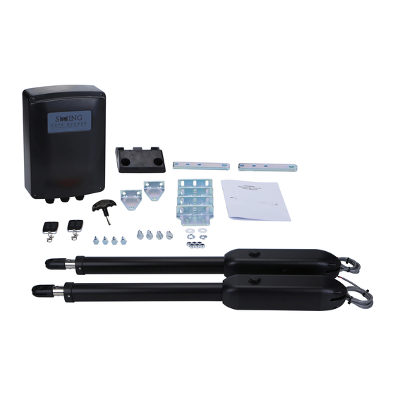
-
Contents
-
Table of Contents
-
Troubleshooting
-
Bookmarks
Quick Links
SW300DC
Swing Gate Opener
User Manual
Related Manuals for JOYTECH SW300DC
Summary of Contents for JOYTECH SW300DC
-
Page 1
SW300DC Swing Gate Opener User Manual… -
Page 2: Table Of Contents
CONTENTS: 1. Safety Instruction……………………1 2. Packing List……………………..2 3. Technical Parameters ……………………4. Installation Drawing…………………….4 5. Tools Needed for Standard Installation………………4 6. Cable List……………………..5 7. Direction of Gate Opening…………………..6 7.1 Gate Opens Inwards……………………6 7.2 Gate Opens Outwards……………………6 8. Installation Steps……………………7 Preparation before Main Machine Installation …………….7 8.1.1 Cable Bury…………………….7 8.1.2 Mounting Brackets Fixing………………….7…
-
Page 3: Safety Instruction
Dear users, Thank you for choosing this product. Please read the manual carefully before assembling and using it. Please do not leave out the manual if you send this product to a third party. 1. Safety Instruction Please read this manual carefully before installation, in which involves with important information about …
-
Page 4: Packing List
2. Packing List (Standard) Picture Name Quantity Main machine Control box Manual release key Remote control Wall bracket Front mounting bracket Connecting bracket Screw M8X25 Mounting screw (short) Screw M8×45 Self-locking Nut M8 Limit stopper…
-
Page 5: Technical Parameters
Due to the difference of installation environment, our company does not provide the installation accessories to fix and connect gate openers and wall. Please prepare the these installation accessories according to actual site situation. 3. Technical Parameters Model SW300DC Power supply 220V/50Hz;110V/60Hz Motor power 18~22s/ 90°…
-
Page 6: Installation Drawing
4. Installation Drawing Figure 1 SW300DC swing gate opener is applicable to single leaf gate weight less than 300kg, and the length shorter 2.5m. The drive mode adopts planetary transmission to combine with the screw rod transmission. than This gate opener must be installed inside the enclosure or yard for protection.
-
Page 7: Cable List
6. Cable List Cable Application Cable Material Max. Length 3×2.5mm² (>30m) Cable of 220V controlbox’s power supply Unlimited 3×1.5mm² (<30m) Cable of gate opener’s power supply 2×1.5mm² Cable of infrared sensor 2×0.5mm² Cable of alarm lamp 2×0.5mm² Cable of electric lock 2×0.5mm²…
-
Page 8: Direction Of Gate Opening
7. Direction of Gate Opening 7.1 Gate Opens Inwards Figure 2 100mm 120 mm 140 mm 160 mm 180 mm 200 mm 100mm 102° 101° 99° 98° 97° 97° 120mm 111° 108° 106° 104° 103° 99° 140mm 118° 115° 112° 102°…
-
Page 9: Installation Steps
8.1.2 Mounting Brackets Fixing In order to install the SW300DC main machines firmly, it is recommended to use the expansion screws to fix the mounting brackets. 8.2 Accessory Installation A) Before installing the main machines, please install the wall bracket on the wall first, then fix the connecting bracket, finally install the front mounting bracket on the gate.
-
Page 10
Figure 4 B) The connecting bracket and the wall bracket can be connected according to different conditions, please refer to figure 5. Figure 5 C) Before the installation, please unlock the two main machines. Unlock method: Open the manual release cover, insert the manual release key, rotate the key until it’s released, as shown in Figure 6, then turn the telescopic arm, you’ll find it’s stretched by hand easily. -
Page 11
Figure 7 E) As shown in figure 8 below, connect wall bracket with wall according to marked position. Then, connect main machine with wall bracket by screw and nut. (Please use spirit level to make sure the installation levelness.) Figure 8 Figure 9… -
Page 12: Dimension Of Control Box
8.3 Dimension of Control Box Figure 10 Note To ensure safety and protect the machines, please install a gate stopper at the open limit position when the gate opens outward to prevent the gate from running over its travel. Meanwhile, to enable the 2 swings to close to its accurate limit position, please install a limit stopper at the closed limit position (as shown in figure 3).
-
Page 13: Wiring And Debugging
9. Wiring and Debugging 9.1 Wiring Instructions FUSE FUSE 10A Mains Mains input input AC24VIN AC24VIN +SOLAR- +SOLAR- +BATT- +BATT- FORCE FORCE SLOW SLOW DOWN DOWN SPEED SPEED PROG PROG + - MOTOR1 MOTOR1 MOTOR2 MOTOR2 -ELOCK+ -ELOCK+ -BLK+ -BLK+ 12V COM EM1 LM1 LM1 EM2…
-
Page 14: Control Board Drawing And Instructions
9.2 Control Board Drawing and Instructions AC24VIN AC24VIN +SOLAR- +SOLAR- +BATT- +BATT- FORCE FORCE SLOW SLOW DOWN DOWN SPEED SPEED PROG PROG + - MOTOR2 -ELOCK+ -ELOCK+ -BLK+ -BLK+ MOTOR1 MOTOR1 MOTOR2 12V COM EM1 LM1 LM1 EM2 EM2 LM2 PH PED COM OSC GND ANT…
-
Page 15: Digital Screen Setting
9.3 Digital Screen Setting When the control board is working, the users can check working state of gate opener by digital screen on the control board. : no input; : under opening state; : under closing state; : error; :manual mode; : travel setting;…
-
Page 16: Trimmer Setting
9.5 Trimmers Setting Obstacle Sensibility Trimmer To adjust the sensitivity of obstacle — clockwise to increase, counterclockwise to reduce the sensitivity of obstacle. If there are environmental effects, such as heavy winds, adjust the trimmer according to environment. Slow Speed Distance Trimmer To adjust slow speed distance — clockwise to increase, counterclockwise to decrease slow speed distance.
-
Page 17: Special Remote Control Key-Button
9.6.3 Special Remote Control Key-button Press and hold the combination keys for 5S. C(stop)+D(single gate) combination key — enter into remote control learning. 9.7 Control Board Settings 9.7.1 Base Menu Press «PROG» to enter into base menu; Digital screen shows “NE”, select other functions of this menu by “+” and “-” buttons. Press «SET»…
-
Page 18
Dual gates single channel mode Remote control mode Four channel mode Single gate single channel mode Delete remote control… -
Page 19: Base Menu Instruction
9.7.2 Base Menu Instruction Menu Option Default/Attention Press «PROG» to enter Press “+”(up) or “-”(down) to select; into base menu. Press “SET” to confirm. Standard mode; O/C/S (Open/Close/Stop). O/S/C standard mode with automatic closing function. When the gate opens, it will automatically close after automatic closing time.
-
Page 20
00-10: Open gate time interval is 0-15 seconds(default 3 seconds). If the interval 3 seconds. Open Gate Time Interval shorter than 2 seconds, then the electric lock cannot be used. Automatic closing time can be set as Automatic Closing Time 15 seconds. -
Page 21: Advanced Menu
9.7.3 Advanced Menu Instruction Long press «PROG» 2 seconds to enter into advanced menu. Digital Screen shows “TL”, press “+”(up) or “-”(down) to select; Short press “SET” to confirm or to enter into sub-menu. Short press “PROG” to exit. If no command for one minute, the menu will automatically exit. Advanced Menu Time of of gate 1 Initial screen…
-
Page 22
Stop block Limit switch mode Hall sensor SW400DC Gate opener secection SW300DC SW200DC Default setting cancellation Factory default setting Factory default setting… -
Page 23: Advanced Menu Instruction
9.7.4 Advanced Menu Instruction Menu Option Default/Attention Long press «PROG» 2 seconds Press “+”(up) or “-”(down) to select; to enter into base menu. Press “SET” to confirm. After automatic learning, the trip is not ideal can be adjusted manually, the Time of of gate1 shorter the time deceleration distance Travel time adjustment…
-
Page 24
Stop block.(Default) Stop block. Limit Switch Mode Hall sensor. SW400DC. SW300DC. (Default) SW300DC. Gate Opener Secection SW200DC. Cancel factory default setting. Factory Default Setting Factory default setting completes. -
Page 25: Others
10. Others 10.1 Maintenance Check whether the gate operates normally every month. For the sake of safety, each gate is suggested to be equipped with infrared protector, and regular inspection is required as well. Before installation and operation of the gate opener, please read all instructions carefully. We reserve the right to change the instruction without prior notice.
-
Page 26
Warranty Warranty Ordinance 1. To repair against this warranty card and invoice during the warranty period. 2. Warranty period: 1 year after the date of invoice. 3. Without unauthorized dismantling, any product broken or damage due to quality problem, we’ll offer the repair service for free or replace for free.
Описание Товара
описание продукта
ФУНКЦИИ
* Технические характеристики сошника с распашным клапаном
* способ движения: Тип поршня с винтовым приводом
* рабочее напряжение: 24 в пост. Тока
* используйте ширину одиночного затвора до 3,5 М.
* используйте вес с одним затвором до 300 КГ
* водонепроницаемый дизайн IP55
* регулируемое усилие
* Регулируемая задержка по времени
* Ручное освобождение
* Панель управления на базе микропроцессора
* Защита рабочего времени
* доступно для подключения фотоэлемента, контурного детектора, устройства считывания карт памяти, резервного аккумулятора и т.д.
Преимущество оператора с распашного борта:
1. Панель управления может подключать проблесковый маячок, фотоэлемент, резервную батарею, солнечную систему, клавиатуру и т. д.
2. Управление одним или одним двигателем с лепестками со смазкой является дополнительным оборудованием.
3. Может регулировать время открытия и закрытия дверцы.
Может быть поден входной сигнал от резервного аккумулятора 4,24 в пост. Тока. (используется большой контроллер, стандартный контроллер имеет малый размер.)
5.можно регулировать работу на высокой скорости.
6. Установка дополнительного пульта ДУ очень просто.
7: Работа с WiFi-устройством для управления воротами в приложении Mobile Phone
2 усиленный двигатель , предварительно смонтированы с двигателем кабели
2 гаечных ключа с ручным переключателем
2 пульта ДУ
1 панель управления
2 x монтажный кронштейн стойки
2 x монтажный кронштейн затвора
1 резиновый ограничитель заслонки
1 инструкция по эксплуатации
1. Напряжение панели управления: 24 в перем. Тока, доступно для резервной батареи 24 В.
2. Диапазон применения: Подходит для
сошник с двумя рычагами и поворотным затвором.
3. Кодовый датчик для передатчика: Собственный настраиваемый код качения.
4. Поддержка пульта ДУ: CAN
Запомните, что в памяти не более 5 передатчиков 120PCS. Символ двигателя: 24 в пост. Тока двигатель x2
Профиль компании
Компания Giant Alarm System CO.,LTD была основана в 2003 году. Наши основные продукты: Беспроводной радиочастотный пульт дистанционного управления, приемник, интеллектуальный открывающий механизм затвора, раздвижной сошник, автоматический барьер стрелы, все виды интеллектуальных плат управления для открывателя ворот и другие принадлежности автоматической системы машины. Как высокотехнологичная компания, занимающаяся производством и торговлей, наша компания охватывает все сферы деятельности: От НИОКР, производства, продаж до обслуживания. Наши основные награды: Национальный высокотехнологичный предприятие, известный бренд Фудзиана, инновационное пилотное предприятие Фудзиана, высокотехнологичное предприятие Фудзиана. Компания Giant занимает площадь 14000 квадратных метров, насчитывающую более 100 сотрудников, и имеет более 10000 мастерских.