

1
< 1> Contents
Contents
Safety Information ………………………………………………………………………………. 2
Specifications ………………………………………………………………………………………3
Rear I/O Panel …………………………………………………………………………………….6
LAN Port LED Status Table ……………………………………………………………………..6
Overview of Components ……………………………………………………………………..7
CPU Socket ……………………………………………………………………………………………8
DIMM Slots ……………………………………………………………………………………………9
PCI_E1~3: PCIe Expansion Slots………………………………………………………………9
SATA1~4: SATA 6Gb/s Connectors ………………………………………………………….10
JFP1, JFP2: Front Panel Connectors ………………………………………………………10
JPWR1~2: Power Connectors ………………………………………………………………..11
JUSB1~2: USB 2.0 Connectors ………………………………………………………………11
JUSB3: USB 3.1 Gen1 Connector ……………………………………………………………12
JAUD1: Front Audio Connector ………………………………………………………………12
JCOM1: Serial Port Connector ……………………………………………………………….12
CPUFAN, SYSFAN1: Fan Connectors ………………………………………………………13
JTPM1: TPM Module Connector……………………………………………………………..14
JCI1: Chassis Intrusion Connector …………………………………………………………14
JBAT1: Clear CMOS (Reset BIOS) Jumper ……………………………………………….15
EZ Debug LED: Debug LED indicators …………………………………………………….15
BIOS Setup ……………………………………………………………………………………….. 16
Entering BIOS Setup……………………………………………………………………………..16
Resetting BIOS …………………………………………………………………………………….17
Updating BIOS ……………………………………………………………………………………..17
Software Description ………………………………………………………………………….18
Installing Windows® 7/ 8.1/ 10 ……………………………………………………………….18
Installing Drivers ………………………………………………………………………………….18
Installing Utilities …………………………………………………………………………………18
MYSTIC LIGHT ……………………………………………………………………………………..19
Thank you for purchasing the MSI® motherboard H110M
PRO-VD PLUS/ H110M PRO-VH PLUS. This User Guide gives
information about board layout, component overview and
BIOS setup.

2Safety Information
Safety Information
yThe components included in this package are prone to damage from electrostatic
discharge (ESD). Please adhere to the following instructions to ensure successful
computer assembly.
yEnsure that all components are securely connected. Loose connections may cause
the computer to not recognize a component or fail to start.
yHold the motherboard by the edges to avoid touching sensitive components.
yIt is recommended to wear an electrostatic discharge (ESD) wrist strap when
handling the motherboard to prevent electrostatic damage. If an ESD wrist strap
is not available, discharge yourself of static electricity by touching another metal
object before handling the motherboard.
yStore the motherboard in an electrostatic shielding container or on an anti-static
pad whenever the motherboard is not installed.
yBefore turning on the computer, ensure that there are no loose screws or metal
components on the motherboard or anywhere within the computer case.
yDo not boot the computer before installation is completed. This could cause
permanent damage to the components as well as injury to the user.
yIf you need help during any installation step, please consult a certified computer
technician.
yAlways turn off the power supply and unplug the power cord from the power outlet
before installing or removing any computer component.
yKeep this user guide for future reference.
yKeep this motherboard away from humidity.
yMake sure that your electrical outlet provides the same voltage as is indicated on
the PSU, before connecting the PSU to the electrical outlet.
yPlace the power cord such a way that people can not step on it. Do not place
anything over the power cord.
yAll cautions and warnings on the motherboard should be noted.
yIf any of the following situations arises, get the motherboard checked by service
personnel:
Liquid has penetrated into the computer.
The motherboard has been exposed to moisture.
The motherboard does not work well or you can not get it work according to user
guide.
The motherboard has been dropped and damaged.
The motherboard has obvious sign of breakage.
yDo not leave this motherboard in an environment above 60C (140F), it may
damage the motherboard.
3
Safety Information Specifications
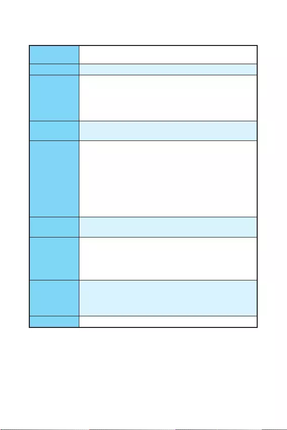
Specifications
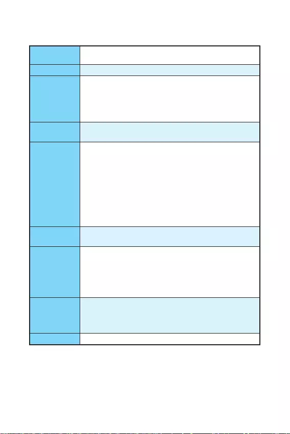
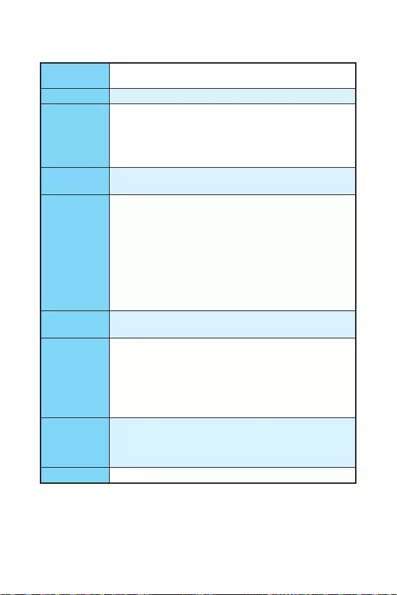
CPU Supports 6th Gen Intel® Core™ i3/i5/i7 processors, and Intel®
Pentium® and Celeron® processors for Socket LGA1151
Chipset Intel® H110 Chipset
Memory
y2x DDR4 memory slots, support up to 32GB
Supports DDR4 2133 MHz
yDual channel memory architecture
ySupports non-ECC, un-buffered memory
ySupports Intel® Extreme Memory Profile (XMP)
Expansion Slots y1x PCIe 3.0 x16 slot
y2x PCIe 2.0 x1 slots
Onboard
Graphics
yH110M PRO-VH PLUS
1x VGA port, supports a maximum resolution of
2048×1536@50Hz, 2048×1280@60Hz, 1920×1200@60Hz
1x HDMI™ port, supports a maximum resolution of
4096×2160@24Hz, 2560×1600@60Hz
yH110M PRO-VD PLUS
1x VGA port, supports a maximum resolution of
2048×1536@50Hz, 2048×1280@60Hz, 1920×1200@60Hz
1x DVI-D port, supports a maximum resolution of
1920×1200@60Hz
Storage Intel® H110 Chipset
y4x SATA 6Gb/s ports
USB
yIntel® H110 Chipset
4x USB 3.1 Gen1 (SuperSpeed USB) ports (2 ports on the
back panel, 2 ports available through the internal USB
connector)
6x USB 2.0 (High-speed USB) ports (2 ports on the back
panel, 4 ports available through the internal USB connectors)
Audio
yRealtek® ALC887 Codec
y7.1-Channel High Definition Audio*
* The HD audio module in the front panel of the chassis is
necessary for 7.1-channel audio output.
LAN 1x Realtek® RTL8111H Gigabit LAN controller
Continued on next page

4Specifications
Continued from previous page
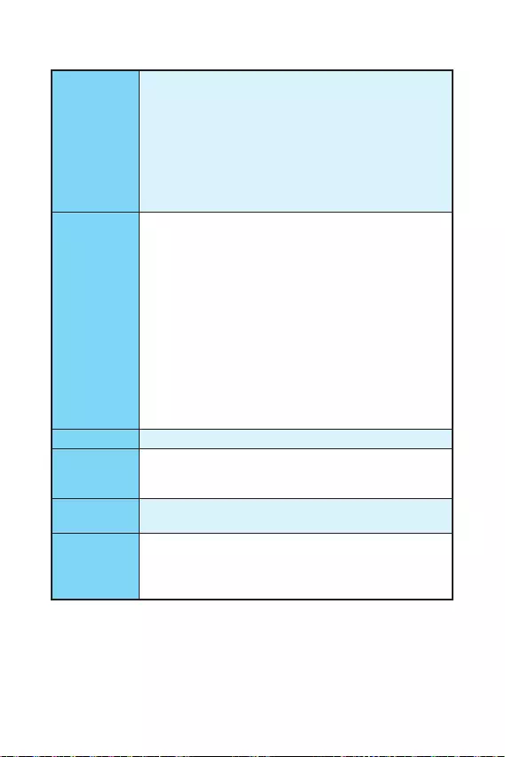
Back Panel
Connectors
y1x PS/2 mouse port
y1x PS/2 keyboard port
y2x USB 3.1 Gen1 ports
y1x HDMI™ port (H110M PRO-VH PLUS)
y1x DVI-D port (H110M PRO-VD PLUS)
y1x VGA port
y1x LAN (RJ45) port
y2x USB 2.0 ports
y3x audio jacks
Internal
Connectors
y1x 24-pin ATX main power connector
y1x 4-pin ATX 12V power connector
y4x SATA 6Gb/s connectors
y2x USB 2.0 connectors (supports additional 4 USB 2.0 ports)
y1x USB 3.1 Gen1 connector (supports additional 2 USB 3.1
Gen1 ports)
y1x 4-pin CPU fan connector
y1x 4-pin system fan connector
y1x Front panel audio connector
y2x Front panel connectors
y1x TPM module connector
y1x Serial Port connector
y1x Chassis Intrusion connector
y1x Clear CMOS jumper
I/O Controller NUVOTON NCT5563D Controller Chip
Hardware
Monitor
yCPU/System temperature detection
yCPU/System fan speed detection
yCPU/System fan speed control
Form Factor yMicro-ATX Form Factor
y8.9 in. x 6.8 in. (22.6 cm x 17.3 cm)
BIOS Features
y1x 64 Mb flash
yUEFI AMI BIOS
yACPI 5.0, PnP 1.0a, SM BIOS 2.8
yMulti-language
Continued on next page

5
Specifications Specifications
Continued from previous page
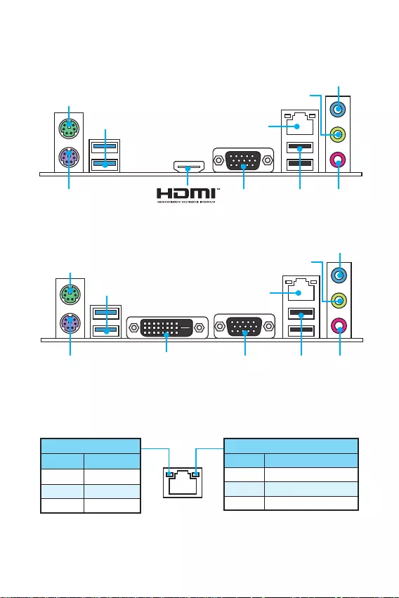
Software
yDrivers
yCOMMAND CENTER
yLIVE UPDATE 6
yFAST BOOT
ySUPER CHARGER
yM-CLOUD
yRAMDISK
yIntel® Small Business Basics
yNETWORK GENIE
yIntel® Extreme Tuning Utility
yNorton™ Security
yGoogle Chrome™,Google Toolbar, Google Drive
yCPU-Z
yMYSTIC LIGHT
MSI Exclusive
Features
yCLICK BIOS
yCOMMAND CENTER
yRAMDISK
ySURPER CHARGER
yFAST BOOT
yLIVE UPDATE 6
yM-CLOUD
yMYSTIC LIGHT
6Rear I/O Panel
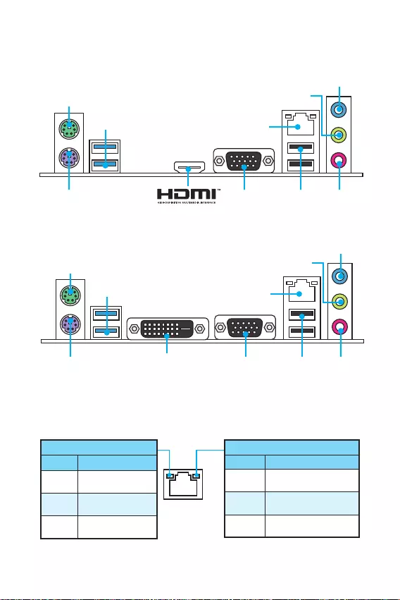
Rear I/O Panel
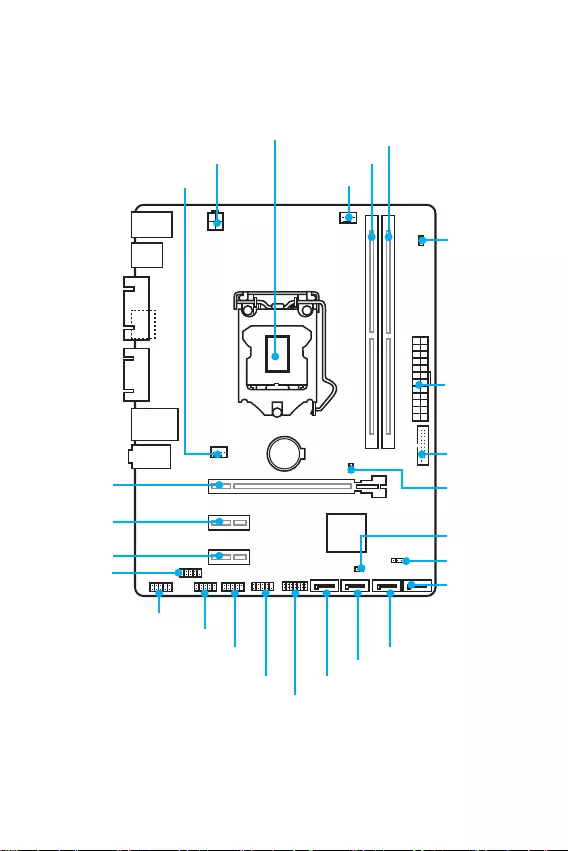
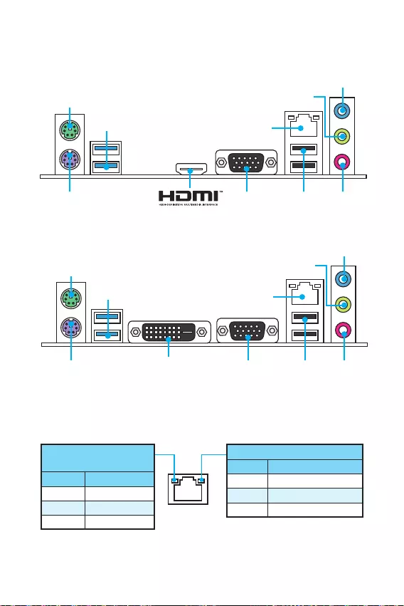
DVI-D
H110M PRO-VD PLUS
PS/2 mouse
LAN
USB 3.1 Gen1
USB 2.0
VGAPS/2
keyboard
H110M PRO-VH PLUS Line-in
Line-out
Mic in
Link/ Activity LED
Status Description
Off No link
Yellow Linked
Blinking Data activity
Speed LED
Status Description
Off 10 Mbps connection
Green 100 Mbps connection
Orange 1 Gbps connection
LAN Port LED Status Table
PS/2 mouse
LAN
USB 3.1 Gen1
VGAPS/2
keyboard
Line-in
Line-out
USB 2.0 Mic in
7
Rear I/O Panel Overview of Components
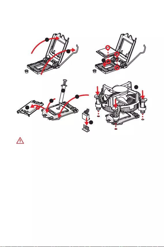
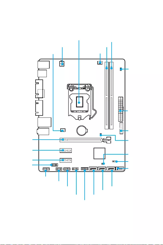
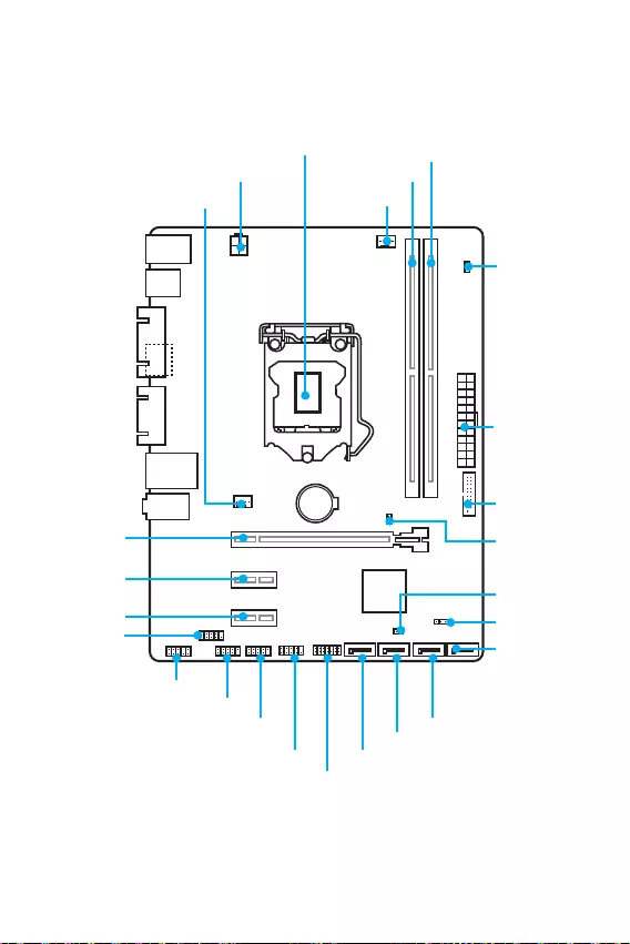
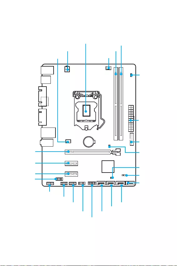
BAT1
DVI- D(optional)
HDMI(optional)
CPUFAN
JPWR2
PCI_E1
PCI_E2
PCI_E3
DIMM1
SYSFAN1
DIMM2
JUSB3
JFP1
JUSB1
SATA1
JFP2
JUSB2
JPWR1
EZ Debug LED
JCI1
SATA2
SATA3
SATA4
JTPM1
JBAT1
JCOM1
CPU Socket
Overview of Components
JAUD1
8Overview of Components
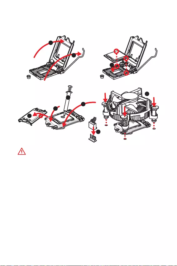
CPU Socket
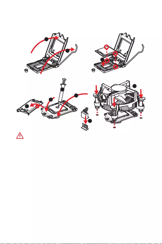
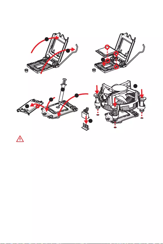
Please install the CPU into the CPU socket as shown below.
Important
y
Always unplug the power cord from the power outlet before installing or removing
the CPU.
y
Please retain the CPU protective cap after installing the processor. MSI will deal
with Return Merchandise Authorization (RMA) requests if only the motherboard
comes with the protective cap on the CPU socket.
y
When installing a CPU, always remember to install a CPU heatsink. A CPU heatsink
is necessary to prevent overheating and maintain system stability.
y
Confirm that the CPU heatsink has formed a tight seal with the CPU before booting
your system.
y
Overheating can seriously damage the CPU and motherboard. Always make sure
the cooling fans work properly to protect the CPU from overheating. Be sure to
apply an even layer of thermal paste (or thermal tape) between the CPU and the
heatsink to enhance heat dissipation.
y
Whenever the CPU is not installed, always protect the CPU socket pins by covering
the socket with the plastic cap.
y
If you purchased a separate CPU and heatsink/ cooler, Please refer to the
documentation in the heatsink/ cooler package for more details about installation.
1
4
6
5
78
9
3
2
9
Overview of Components Overview of Components
DIMM Slots
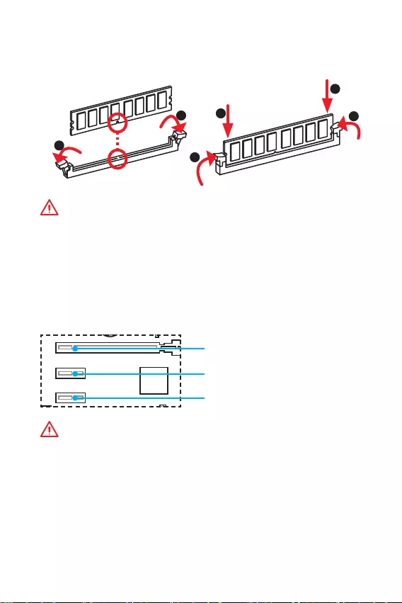
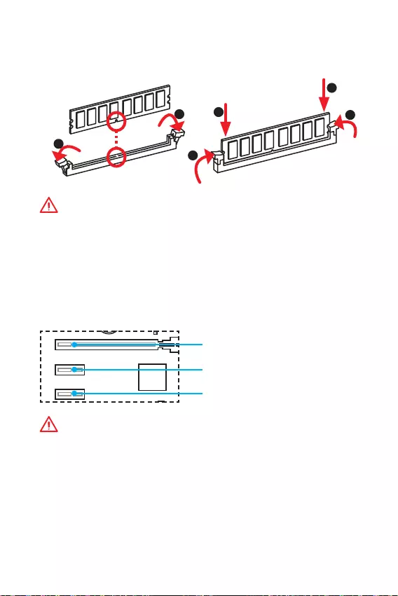
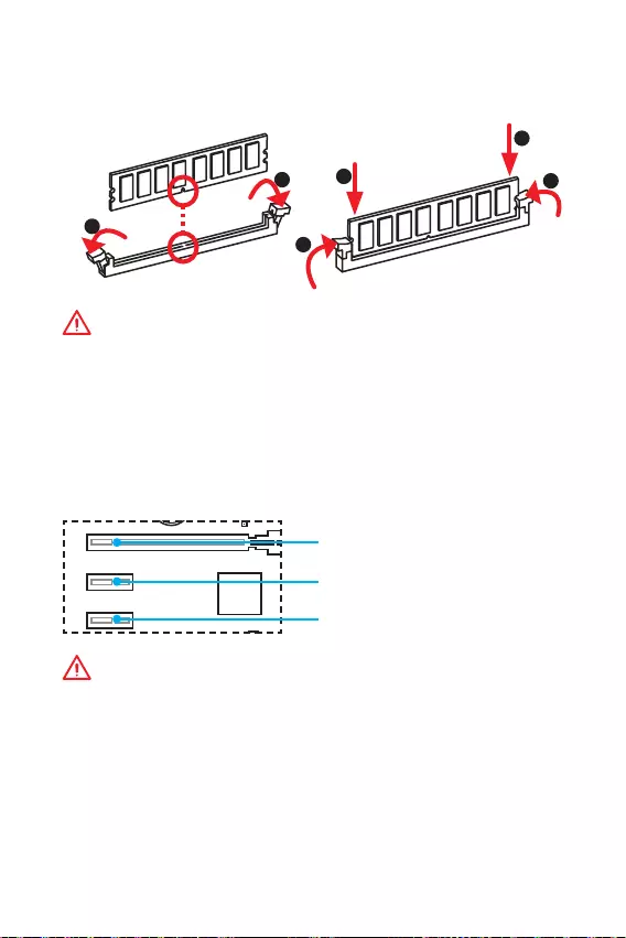
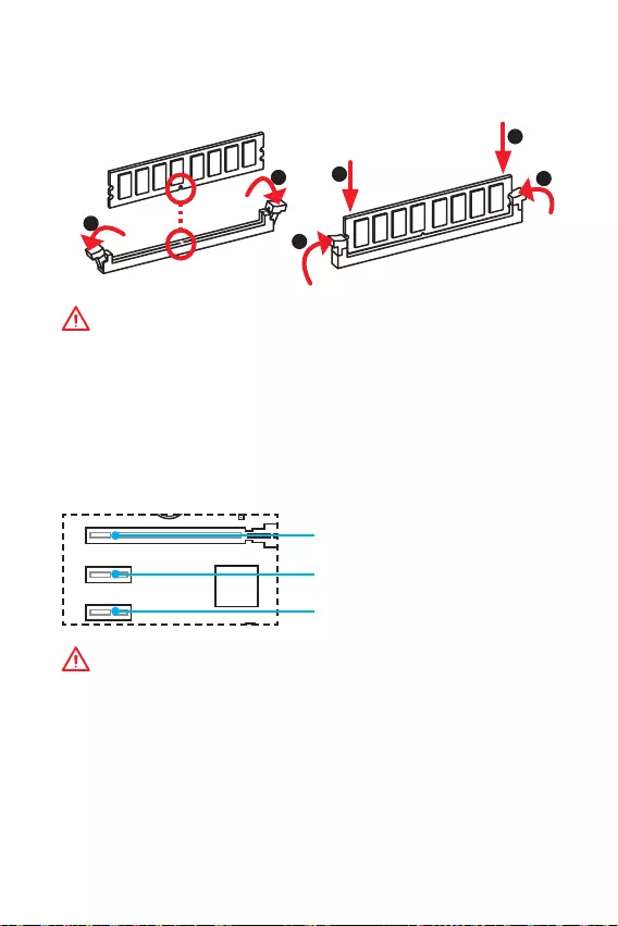
Please install the memory module into the DIMM slot as shown below.
Important
y
Due to chipset resource usage, the available capacity of memory will be a little less
than the amount of installed.
y
Please note that the maximum capacity of addressable memory is 4GB or less
for 32-bit Windows OS due to the memory address limitation. Therefore, we
recommended that you to install 64-bit Windows OS if you want to install more than
4GB memory on the motherboard.
PCI_E1~3: PCIe Expansion Slots
BAT1
DVI- D(optional)
HDMI(optional)
PCI_E1: PCIe 3.0 x16 slot
PCI_E2: PCIe 2.0×1 slot
PCI_E3: PCIe 2.0×1 slot
Important
When adding or removing expansion cards, always turn off the power supply and
unplug the power supply power cable from the power outlet. Read the expansion
cards documentation to check for any necessary additional hardware or software
changes.
1
12
3
3
2
10 Overview of Components
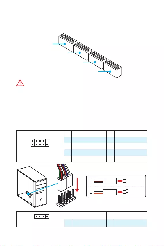
SATA1~4: SATA 6Gb/s Connectors
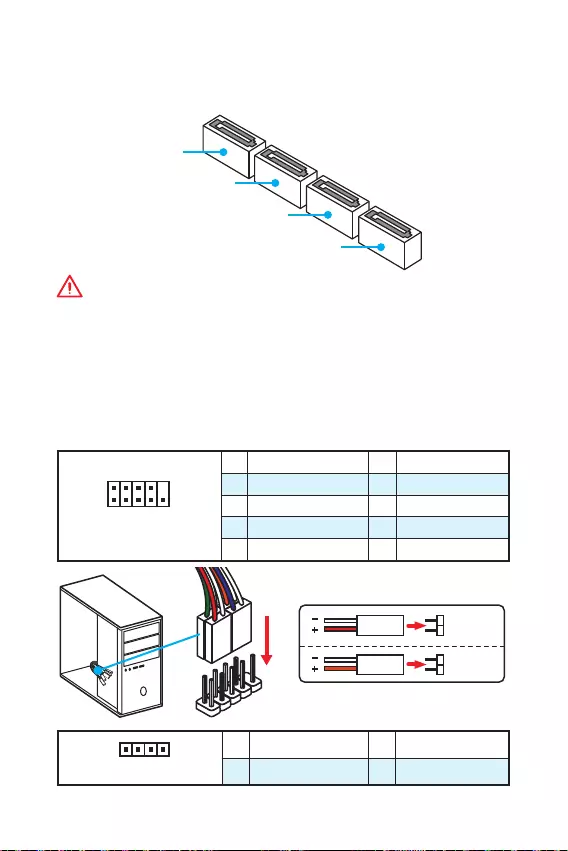
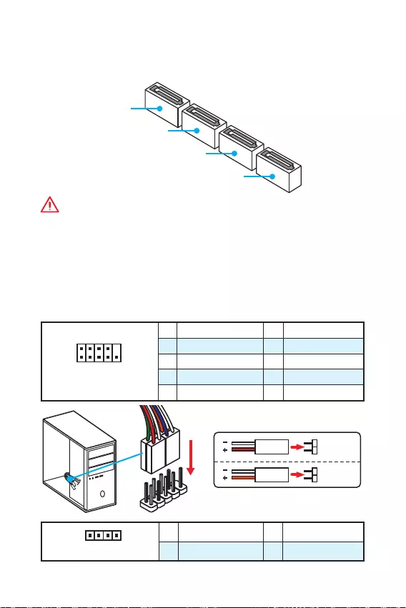
These connectors are SATA 6Gb/s interface ports. Each connector can connect to one
SATA device.
SATA3
SATA2
SATA4
SATA1
Important
y
Please do not fold the SATA cable at a 90-degree angle. Data loss may result during
transmission otherwise.
y
SATA cable has identical plugs on either sides of the cable. However, it is
recommended that the flat connector be connected to the motherboard for space
saving purposes.
JFP1, JFP2: Front Panel Connectors
These connectors connect to the switches and LEDs on the front panel.
1
2 10
9
JFP1
1 HDD LED + 2 Power LED +
3 HDD LED — 4 Power LED —
5 Reset Switch 6 Power Switch
7 Reset Switch 8 Power Switch
9 Reserved 10 No Pin
1
JFP2
1 Speaker — 2 Buzzer +
3 Buzzer — 4 Speaker +
HDD LED
RESET SW
HDD LED HDD LED —
HDD LED +
POWER LED —
POWER LED +
POWER LED
JFP1
11
Overview of Components Overview of Components
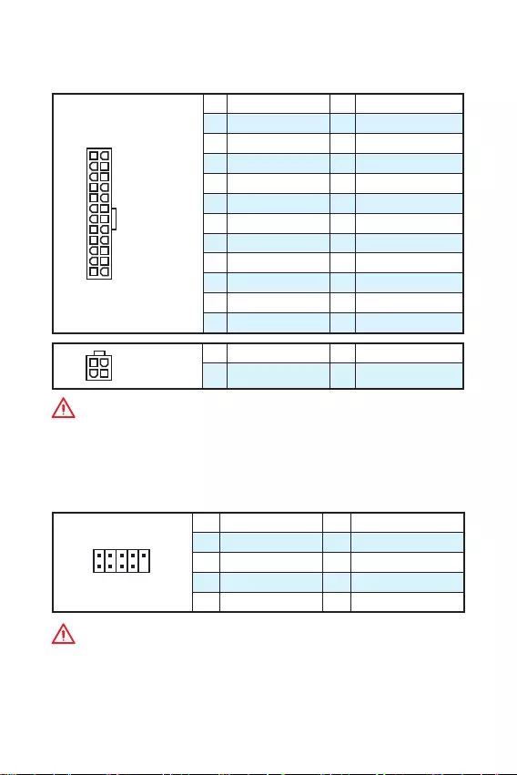
JPWR1~2: Power Connectors
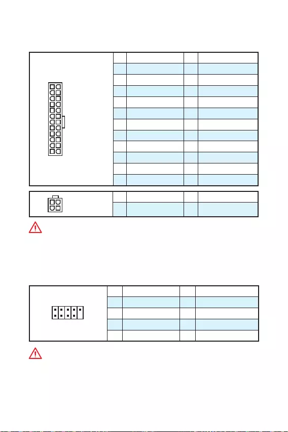
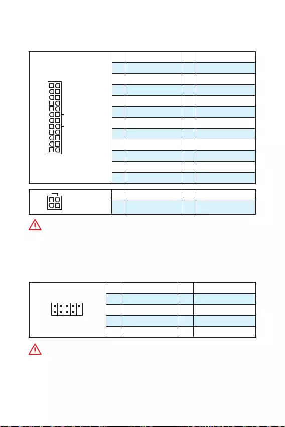
These connectors allow you to connect an ATX power supply.
24
131
12
JPWR1
1 +3.3V 13 +3.3V
2 +3.3V 14 -12V
3 Ground 15 Ground
4 +5V 16 PS-ON#
5 Ground 17 Ground
6 +5V 18 Ground
7 Ground 19 Ground
8 PWR OK 20 Res
9 5VSB 21 +5V
10 +12V 22 +5V
11 +12V 23 +5V
12 +3.3V 24 Ground
3
2 1
4JPWR2
1 Ground 3 +12V
2 Ground 4 +12V
Important
Make sure that all the power cables are securely connected to a proper ATX power
supply to ensure stable operation of the motherboard.
JUSB1~2: USB 2.0 Connectors
These connectors allow you to connect USB 2.0 ports on the front panel.
1
2 10
9
1VCC 2VCC
3 USB0- 4 USB1-
5 USB0+ 6 USB1+
7 Ground 8 Ground
9 No Pin 10 NC
Important
y
Note that the VCC and Ground pins must be connected correctly to avoid possible
damage.
y
In order to recharge your iPad,iPhone and iPod through USB ports, please install
MSI® SUPER CHARGER utility.
12 Overview of Components
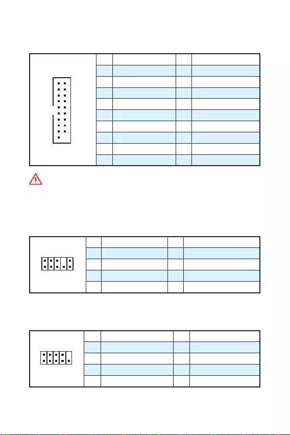
JUSB3: USB 3.1 Gen1 Connector
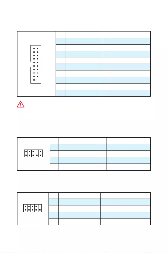
This connector allows you to connect USB 3.1 Gen1 ports on the front panel.
1
10 11
20
1Power 11 USB2.0+
2 USB3_RX_DN 12 USB2.0-
3 USB3_RX_DP 13 Ground
4 Ground 14 USB3_TX_C_DP
5 USB3_TX_C_DN 15 USB3_TX_C_DN
6 USB3_TX_C_DP 16 Ground
7 Ground 17 USB3_RX_DP
8 USB2.0- 18 USB3_RX_DN
9 USB2.0+ 19 Power
10 Ground 20 No Pin
Important
Note that the Power and Ground pins must be connected correctly to avoid possible
damage.
JAUD1: Front Audio Connector
This connector allow you to connect audio jacks on the front panel.
1
2 10
9
1 MIC L 2 Ground
3 MIC R 4 NC
5 Head Phone R 6 MIC Detection
7 SENSE_SEND 8 No Pin
9 Head Phone L 10 Head Phone Detection
JCOM1: Serial Port Connector
This connector allows you to connect the optional serial port with bracket.
1
2 10
9
1 DCD 2 SIN
3 SOUT 4 DTR
5 Ground 6 DSR
7 RTS 8 CTS
9 RI 10 No Pin
13
Overview of Components Overview of Components
CPUFAN, SYSFAN1: Fan Connectors
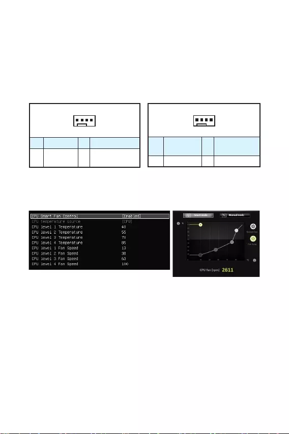
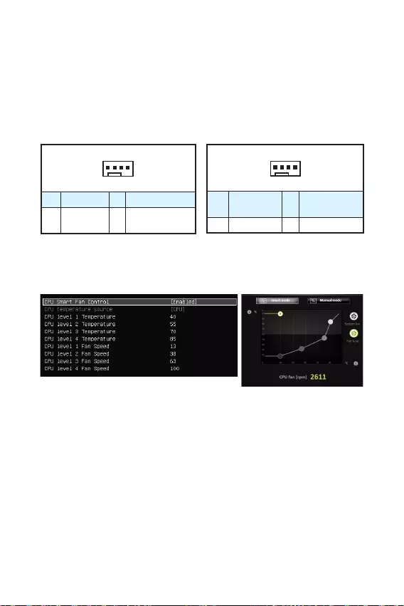
Fan connectors can be classified as PWM (Pulse Width Modulation) Mode and Voltage
Mode. PWM Mode fan connectors provide constant 12V output and adjust fan speed
with speed control signal. Voltage Mode fan connectors control fan speed by changing
voltage. Therefore, when you plug a 3-pin (Non-PWM) fan to a PWM Mode fan
connector, the fan speed will be always maintained at 100%, and that could be noisy.
1
CPUFAN
1 Ground 2 +12V
3 Sense 4 Speed Control
Signal
1
SYSFAN1
1 Ground 2 Voltage
Control
3 Sense 4 NC
PWM Mode fan connector Voltage Mode fan connector
Controlling the fan speed
There are two ways to manage fan speed. One is to go to BIOS > Advanced >
Hardware Monitor. The other is to use COMMAND CENTER application.
COMMAND CENTER
BIOS Hardware Monitor sub-menu allows you to set the temperature levels and the
corresponding fan speed levels.
COMMAND CENTER offers gradient points of the fan speed that allow you to adjust
fan speed in relation to CPU temperature.
BIOS > Advanced > Hardware Monitor
14 Overview of Components
JTPM1: TPM Module Connector
This connector is for TPM (Trusted Platform Module). Please refer to the TPM
security platform manual for more details and usages.
1
2 14
13
1 LPC Clock 2 3V Standby power
3 LPC Reset 4 3.3V Power
5 LPC address & data pin0 6 Serial IRQ
7 LPC address & data pin1 8 5V Power
9 LPC address & data pin2 10 No Pin
11 LPC address & data pin3 12 Ground
13 LPC Frame 14 Ground
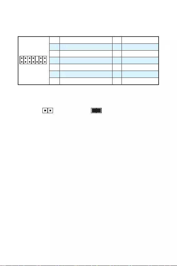
JCI1: Chassis Intrusion Connector
This connector allows you to connect the chassis intrusion switch cable.
Normal
(default)
Trigger the chassis
intrusion event
Using chassis intrusion detector
1. Connect the JCI1 connector to the chassis intrusion switch/ sensor on the
chassis.
2. Close the chassis cover.
3. Go to BIOS > Security > Chassis Intrusion Configuration.
4. Set Chassis Intrusion to Enabled.
5. Press F10 to save and exit and then press the Enter key to select Yes.
6. Once the chassis cover is opened again, a warning message will be displayed on
screen when the computer is turned on.
Resetting the chassis intrusion warning
1. Go to BIOS > Security > Chassis Intrusion Configuration.
2. Set Chassis Intrusion to Reset.
3. Press F10 to save and exit and then press the Enter key to select Yes.

15
Overview of Components Overview of Components
JBAT1: Clear CMOS (Reset BIOS) Jumper
There is CMOS memory onboard that is external powered from a battery located on
the motherboard to save system configuration data. If you want to clear the system
configuration, set the jumper to clear the CMOS memory.
Keep Data
(default)
Clear CMOS/ Reset
BIOS
Resetting BIOS to default values
1. Power off the computer and unplug the power cord.
2. Use a jumper cap to short JBAT1 for about 5-10 seconds.
3. Remove the jumper cap from JBAT1.
4. Plug the power cord and power on the computer.
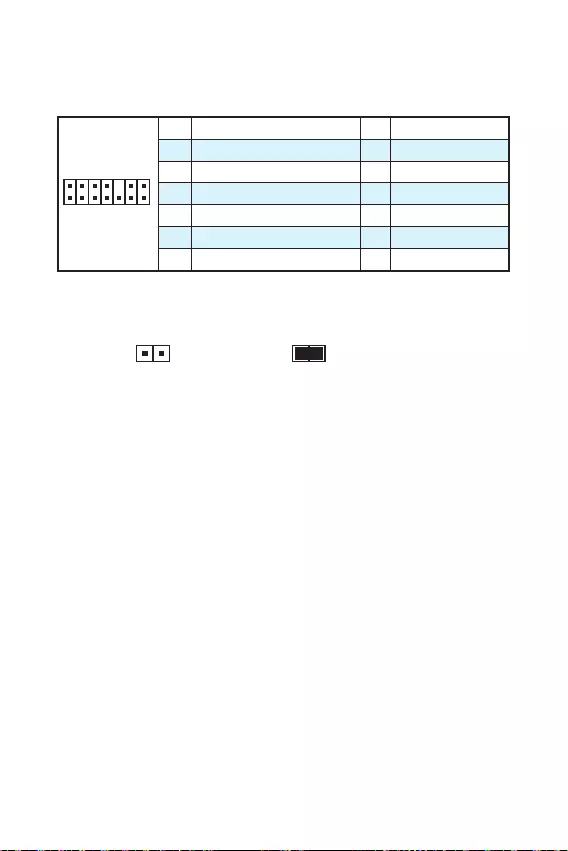
EZ Debug LED: Debug LED indicators
These LEDs indicate the status of the motherboard.
CPU — indicates CPU is not detected or fail.
DRAM — indicates DRAM is not detected or fail.
VGA — indicates GPU is not detected or fail.
16 BIOS Setup
BIOS Setup
The default settings offer the optimal performance for system stability in normal
conditions. You should always keep the default settings to avoid possible system
damage or failure booting unless you are familiar with BIOS.
Important
y
BIOS items are continuous update for better system performance. Therefore, the
description may be slightly different from the latest BIOS and should be held for
reference only. You could also refer to the HELP information panel for BIOS item
description.
y
The pictures in this chapter are for reference only and may vary from the product
you purchased.
Entering BIOS Setup
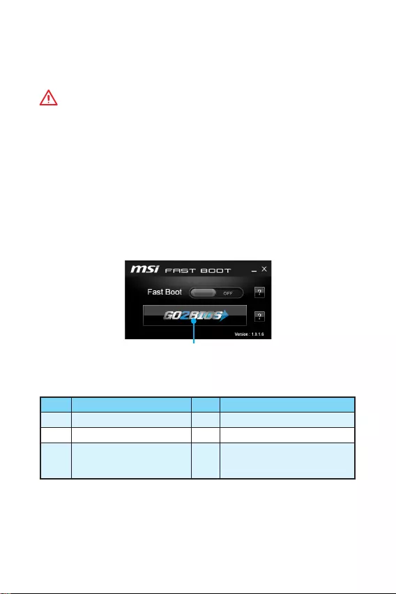
Please refer the following methods to enter BIOS setup.
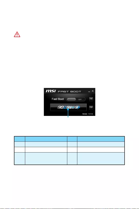
yPress Delete key, when the Press DEL key to enter Setup Menu, F11 to enter Boot
Menu message appears on the screen during the boot process.
yUse MSI FAST BOOT application. Click on GO2BIOS button and choose OK. The
system will reboot and enter BIOS setup directly.
Click on GO2BIOS
Function key
Key Function Key Function
F1 General Help F4 Enter CPU Specifications menu
F5 Enter Memory-Z menu F6 Load optimized defaults
F10 Save Change and Reset* F12
Take a screenshot and save it
to USB flash drive (FAT/ FAT32
format only).
* When you press F10, a confirmation window which provides the modification
information appears. Select between Yes or No to confirm your choice.

17
BIOS Setup BIOS Setup
Resetting BIOS
You might need to restore the default BIOS setting to solve certain problems. There
are several ways to reset BIOS:
yGo to BIOS and press F6 to load optimized defaults.
yShort the Clear CMOS jumper on the motherboard.
Important
Please refer to the Clear CMOS Jumper section for resetting BIOS.
Updating BIOS
Updating BIOS with M-FLASH
Before updating:
Please download the latest BIOS file that matches your motherboard model from MSI
website. And then save the BIOS file into the USB flash drive.
Updating BIOS:
1. Insert the USB flash drive that contains the update file into the computer.
2. Reboot the system, and then press Del key to enter the BIOS Setup during POST.
3. Go to BIOS > M-FLASH > Select one file to update BIOS and ME, select a BIOS file
to perform the BIOS update process.
4. After the flashing process is 100% complete, the system will reboot.
Updating the BIOS with Live Update 6
Before updating:
Make sure the LAN driver is already installed and the internet connection is set
properly.
Updating BIOS:
1. Install and launch MSI LIVE UPDATE 6.
2. Select Manual scan.
3. Check MB BIOS box and click on Scan button.
4. Select the MB BIOS and click on icon to download and install the latest BIOS
file.
5. Click Next and choose In Windows mode. And then click Next and Start to start
updating BIOS.
6. After the flashing process is 100% completed, the system will restart
automatically.

18 Software Description
Software Description
Installing Windows® 7/ 8.1/ 10
1. Power on the computer.
2. Insert the Windows® 7/ 8.1/ 10 disc into your optical drive.
Note: Due to chipset limitation, during the Windows® 7 installation process, USB
optical drives or USB pen drives are not supported.
3. Press the Restart button on the computer case.
4. For windows® 8.1/ 10, skip this step. For Windows® 7, access the BIOS menu
Advanced > Windows OS Configuration > Windows 7 Installation and set the item
to enabled, save changes and restart.
Note: It is suggested to plug in your USB Keyboard/USB Mouse to the leftmost
USB port when installing Windows® 7.
5. Press F11 key during the computer POST (Power-On Self Test) to get into Boot
Menu.
6. Select your optical drive from the Boot Menu.
7. Press any key when screen shows Press any key to boot from CD or DVD…
message.
8. Follow the instructions on the screen to install Windows® 7/ 8.1/ 10.
Installing Drivers
1. Start up your computer in Windows® 7/ 8.1/ 10.
2. Insert MSI® Driver Disc into your optical drive.
3. The installer will automatically appear and it will find and list all necessary
drivers.
4. Click Install button.
5. The software installation will then be in progress, after it has finished it will
prompt you to restart.
6. Click OK button to finish.
7. Restart your computer.
Installing Utilities
Before you install utilities, you must complete drivers installation.
1. Insert MSI® Driver Disc into your optical drive.
2. The installer will automatically appear.
3. Click Utilities tab.
4. Select the utilities you want to install.
5. Click Install button.
6. The utilities installation will then be in progress, after it has finished it will
prompt you to restart.
7. Click OK button to finish.
8. Restart your computer.
19
Software Description Software Description
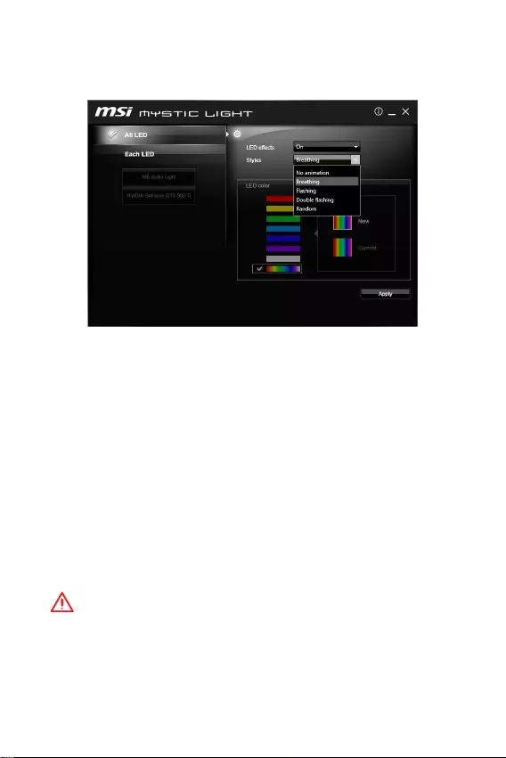
MYSTIC LIGHT
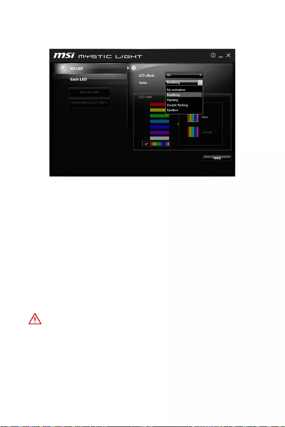
MYSTIC LIGHT allows you to control LED lights on your motherboard and graphics
cards.
yAll LED — controls all LEDs on your motherboard and graphics cards.
yEach LED — separately controls each segment of LEDs on your motherboard and
graphics cards.
yLED effects — switches LEDs on or off.
yStyles — selects the LED style from the drop-down list.
yLED color (optional) — allows you to change the LED color. This option depends on
the motherboard you purchased.
yApply Button — applies Styles settings to LEDs.
Audio line control
yDefault Audio line setting in BIOS is Breathing.
yAfter installing MYSTIC LIGHT and reboot to OS, the default style of Audio line will
switch to No animation. Once we change Audio line style in MYSTIC LIGHT and click
Apply, the software will immediately re-program the Audio line style in both BIOS
and OS.
Note: Audio line styles will change to No animation if user shuts down the MYSTIC
LIGHT in OS.
Important
y
It is recommended to control Audio line style by MYSTIC LIGHT.
y
Audio line will be in Breathing mode under DOS when you select the following
styles Flashing, Double Flashing and Random.

20 NOTE
NOTE

1
< 1>
…………………………………………………………………………………………….. 2
…………………………………………………………………………………………………….3
I/O ………………………………………………………………………………………..6
LAN LED ………………………………………………………………………..6
…………………………………………………………………………………………………….7
CPU ……………………………………………………………………………………………….8
DIMM ……………………………………………………………………………………………..9
PCI_E1~3: PCIe ………………………………………………………………………..9
SATA1~4: SATA 6Gb/s …………………………………………………………………10
JFP1, JFP2: ………………………………………………………………….10
JPWR1~2: …………………………………………………………………………..11
JUSB1~2: USB 2.0 ………………………………………………………………………11
JUSB3: USB 3.1 Gen1 ………………………………………………………………….12
JAUD1: ……………………………………………………………………..12
JCOM1: …………………………………………………………………….12
CPUFAN, SYSFAN1: ………………………………………………………………..13
JTPM1: TPM ………………………………………………………………………..14
JCI1: ……………………………………………………………………………14
JBAT1: CMOS (Reset BIOS) …………………………………………………..15
EZ Debug LED: LED ………………………………………………………….15
BIOS …………………………………………………………………………………………..16
BIOS …………………………………………………………………………………………….16
BIOS …………………………………………………………………………………………….17
BIOS ………………………………………………………………………………………17
…………………………………………………………………………………..18
Windows® 7/ 8.1/ 10 …………………………………………………………………18
………………………………………………………………………………….18
………………………………………………………………………………….18
MYSTIC LIGHT ……………………………………………………………………………………..19
MSI® H110M PRO-VD PLUS/ H110M PRO-VH PLUS
.
, , BIOS .

2
y (ESD)
.
y . ,
.
y
.
y (ESD)
. ESD ,
.
y
.
y
.
y . ,
.
y .
y
.
y .
y .
yPSU PSU
.
y . .
y .
y , .
.
.
.
.
.
y 60C (140F) . .
3
CPU 6 Intel® Core™ i3/i5/i7 LGA1151
Intel® Pentium® Celeron® .
Intel® H110
yDDR4 2, 32GB
DDR4 2133 MHz
y
ynon-ECC, un-buffered
yIntel® Extreme Memory Profile (XMP)
yPCIe 3.0 x16 1
yPCIe 2.0 x1 2
yH110M PRO-VH PLUS
VGA 1, 2048×1536@50Hz, 2048×1280@60Hz,
1920×1200@60Hz
HDMI™ 1, 4096×2160@24Hz, 2560×1600@60Hz
yH110M PRO-VD PLUS
VGA 1, 2048×1536@50Hz, 2048×1280@60Hz,
1920×1200@60Hz
DVI-D 1, 1920×1200@60Hz
Intel® H110
ySATA 6Gb/s 4
USB
yIntel® H110
USB 3.1 Gen1 (SuperSpeed USB) 4 ( 2
, USB 2 )
USB 2.0 (High-speed USB) 6 ( 2,
USB 4 )
yRealtek® ALC887
y7.1- HD *
* HD 7.1-
.
LAN Realtek® RTL8111H Gigabit LAN 1

4
yPS/2 1
yPS/2 1
yUSB 3.1 Gen1 2
yHDMI™ 1 (H110M PRO-VH PLUS)
yDVI-D 1 (H110M PRO-VD PLUS)
yVGA 1
yLAN (RJ45) 1
yUSB 2.0 2
y 3
y24 ATX 1
y4 ATX 12V 1
ySATA 6Gb/s 4
yUSB 2.0 2 ( USB 2.0 4)
yUSB 3.1 Gen1 1 ( USB 3.1 Gen1 2)
y4- CPU 1
y4- 1
y 1
y 2
yTPM 1
y 1
y 1
yCMOS 1
I/O NUVOTON NCT5563D
yCPU/
yCPU/
yCPU/
yMicro-ATX
y8.9 in. x 6.8 in. (22.6 cm x 17.3 cm)
BIOS
y64 Mb 1
yUEFI AMI BIOS
yACPI 5.0, PnP 1.0a, SM BIOS 2.8
y

5
y
yCOMMAND CENTER
yLIVE UPDATE 6
yFAST BOOT
ySUPER CHARGER
yM-CLOUD
yRAMDISK
yIntel® Small Business Basics
yNETWORK GENIE
y®
yNorton™
yGoogle Chrome™,Google Toolbar, Google Drive
yCPU-Z
yMYSTIC LIGHT
MSI Exclusive
yCLICK BIOS
yCOMMAND CENTER
yRAMDISK
ySURPER CHARGER
yFAST BOOT
yLIVE UPDATE 6
yM-CLOUD
yMYSTIC LIGHT
6 I/O
I/O
DVI-D
H110M PRO-VD PLUS
PS/2
LAN
USB 3.1 Gen1
USB 2.0
VGAPS/2
H110M PRO-VH PLUS
/ LED
LAN
.
LAN
.
LAN
.
LED
10 Mbps
.
100 Mbps
.
1 Gbps
.
LAN LED
PS/2
LAN
USB 3.1 Gen1
VGAPS/2
USB 2.0
7
I/O
BAT1
DVI- D(optional)
HDMI(optional)
CPUFAN
JPWR2
PCI_E1
PCI_E2
PCI_E3
DIMM1
SYSFAN1
DIMM2
JUSB3
JFP1
JUSB1
SATA1
JFP2
JUSB2
JPWR1
EZ Debug LED
JCI1
SATA2
SATA3
SATA4
JTPM1
JBAT1
JCOM1
CPU
JAUD1
8
CPU
CPU CPU .
y
CPU .
y
, CPU . CPU
MSI (RMA) .
y
CPU , CPU . CPU
.
y
CPU .
y
CPU CPU
. CPU
( ) .
y
CPU , CPU
.
y
CPU / , /
.
1
4
6
5
78
9
3
2
9
DIMM
DIMM .
y
.
y
4GB 32-(Windows OS)
. 4GB 64-
Windows OS .
PCI_E1~3: PCIe
BAT1
DVI- D(optional)
HDMI(optional)
PCI_E1: PCIe 3.0 x16
PCI_E2: PCIe 2.0×1
PCI_E3: PCIe 2.0×1
.
.
1
12
3
3
2
10
SATA1~4: SATA 6Gb/s
SATA 6Gb/s . SATA
.
SATA3
SATA2
SATA4
SATA1
y
SATA 90 . , .
y
SATA
.
JFP1, JFP2:
LED .
1
2 10
9
JFP1
1 HDD LED + 2 Power LED +
3 HDD LED — 4 Power LED —
5 Reset Switch 6 Power Switch
7 Reset Switch 8 Power Switch
9 Reserved 10 No Pin
1
JFP2
1 Speaker — 2 Buzzer +
3 Buzzer — 4 Speaker +
HDD LED
RESET SW
HDD LED HDD LED —
HDD LED +
POWER LED —
POWER LED +
POWER LED
JFP1
11
JPWR1~2:
ATX .
24
131
12
JPWR1
1 +3.3V 13 +3.3V
2 +3.3V 14 -12V
3 Ground 15 Ground
4 +5V 16 PS-ON#
5 Ground 17 Ground
6 +5V 18 Ground
7 Ground 19 Ground
8 PWR OK 20 Res
9 5VSB 21 +5V
10 +12V 22 +5V
11 +12V 23 +5V
12 +3.3V 24 Ground
3
2 1
4JPWR2
1 Ground 3 +12V
2 Ground 4 +12V
ATX
.
JUSB1~2: USB 2.0
USB 2.0 .
1
2 10
9
1VCC 2VCC
3 USB0- 4 USB1-
5 USB0+ 6 USB1+
7 Ground 8 Ground
9 No Pin 10 NC
y
VCC .
y
USB iPad, iPhone iPod MSI® SUPER CHARGER
.
12
JUSB3: USB 3.1 Gen1
USB 3.1 Gen1 .
1
10 11
20
1Power 11 USB2.0+
2 USB3_RX_DN 12 USB2.0-
3 USB3_RX_DP 13 Ground
4 Ground 14 USB3_TX_C_DP
5 USB3_TX_C_DN 15 USB3_TX_C_DN
6 USB3_TX_C_DP 16 Ground
7 Ground 17 USB3_RX_DP
8 USB2.0- 18 USB3_RX_DN
9 USB2.0+ 19 Power
10 Ground 20 No Pin
.
JAUD1:
.
1
2 10
9
1 MIC L 2 Ground
3 MIC R 4 NC
5 Head Phone R 6 MIC Detection
7 SENSE_SEND 8 No Pin
9 Head Phone L 10 Head Phone Detection
JCOM1:
.
1
2 10
9
1 DCD 2 SIN
3 SOUT 4 DTR
5 Ground 6 DSR
7 RTS 8 CTS
9 RI 10 No Pin
13
CPUFAN, SYSFAN1:
PWM (Pulse Width Modulation) .
PWM 12V
. .
PWM 3- (Non-PWM) , 100%
.
1
CPUFAN
1 Ground 2 +12V
3 Sense 4 Speed Control
Signal
1
SYSFAN1
1 Ground 2 Voltage
Control
3 Sense 4 NC
PWM
2 . BIOS > Advanced >
Hardware Monitor COMMAND CENTER
.
COMMAND CENTER
BIOS Hardware Monitor
.
COMMAND CENTER CPU
.
BIOS > Advanced > Hardware Monitor
14
JTPM1: TPM
TPM (Trusted Platform Module) .
TPM .
1
2 14
13
1 LPC Clock 2 3V Standby power
3 LPC Reset 4 3.3V Power
5 LPC address & data pin0 6 Serial IRQ
7 LPC address & data pin1 8 5V Power
9 LPC address & data pin2 10 No Pin
11 LPC address & data pin3 12 Ground
13 LPC Frame 14 Ground
JCI1:
.
( )
1. JCI1 / .
2. .
3. BIOS > Security() > Chassis Intrusion Configuration( )
.
4. Chassis Intrusion( ) Enabled() .
5. F10 . Enter Yes .
6. .
1. BIOS > Security() > Chassis Intrusion Configuration( )
.
2. Chassis Intrusion( ) Reset() .
3. F10 . Enter Yes .

15
JBAT1: CMOS (Reset BIOS)
CMOS
. CMOS
.
( )
CMOS
/BIOS
BIOS
1.
2. JBAT1 5-10 .
3. JBAT1 .
4. .
EZ Debug LED: LED
LED .
CPU — CPU .
DRAM — DRAM .
VGA — GPU .
16 BIOS
BIOS
. BIOS
,
.
y
BIOS .
BIOS .
BIOS HELP() .
y
.
BIOS
BIOS .
y Press DEL key to enter Setup Menu, F11 to enter Boot
Menu(DEL , F11 )
Delete .
yMSI FAST BOOT . GO2BIOS OK
BIOS .
GO2BIOS
F1 F4 CPU
F5 Memory-Z F6
F10 * F12
Take a screenshot and save it
to USB flash drive (FAT/ FAT32
format only).
* F10 . Yes
No .

17
BIOS BIOS
BIOS
BIOS . BIOS
.
yBIOS F6 .
y CMOS .
BIOS CMOS .
BIOS
M-FLASH BIOS
BIOS MSI® BIOS USB
.
BIOS
1. USB .
2. POST Del BIOS .
3. BIOS > M-FLASH > Select one file to update BIOS and ME , BIOS
BIOS .
4. 100% .
Live Update 6 BIOS
LAN .
BIOS
1. MSI LIVE UPDATE 6 .
2. Manual scan .
3. MB BIOS box Scan .
4. MB BIOS BIOS
.
5. Next Windows mode Next Start BIOS
.
6. 100% .

18
Windows® 7/ 8.1/ 10
1. .
2. Windows® 7/ 8.1/ 10 .
: Windows® 7 USB USB
.
3. Restart .
4. Windows® 8.1/ 10 , . Windows® 7
, BIOS . Advanced > Windows OS Configuration
> Windows 7 Installation []
.
: Windows® 7 USB / USB
.
5. POST (Power-On Self Test) F11 .
6. .
7. Press any key to boot from CD or DVD…
.
8. Windows® 7/ 8.1/ 10 .
1. Windows® 7/ 8.1/ 10 .
2. MSI® .
3. .
4. Install .
5. . .
6. OK .
7. .
.
1. MSI® .
2. .
3. Utilities .
4. .
5. Install .
6. . .
7. OK .
8. .
19
MYSTIC LIGHT
MYSTIC LIGHT LED .
yAll LED — LED .
yEach LED — LED .
yLED — LED .
y — LED .
yLED () — LED .
.
y — LED .
yBIOS (Breathing) .
yMYSTIC LIGHT OS
. MYSTIC LIGHT
BIOS OS
.
: OS MYSTIC LIGHT .
y
MYSTIC LIGHT .
y
(Flashing), (Double Flashing) (Random)를
DOS (Breathing) .

20 NOTE
NOTE

1
< 1> Table des matières
Table des matières
Informations de sécurité ……………………………………………………………………… 2
Spécifications ………………………………………………………………………………………3
Panneau arrière Entrée/ Sortie …………………………………………………………….6
Tableau explicatif de létat de la LED du port LAN …………………………………….6
Vue densemble des composants ………………………………………………………….7
Socket processeur ………………………………………………………………………………….8
Slots DIMM …………………………………………………………………………………………..9
PCI_E1~3: Slots d’extension PCIe …………………………………………………………….9
SATA1~4: Connecteurs SATA 6 Gb/s ……………………………………………………….10
JFP1, JFP2: Connecteurs de panneau avant ……………………………………………10
JPWR1~2: Connecteurs dalimentation ………………………………………………….11
JUSB1~2: Connecteurs USB 2.0 …………………………………………………………….11
JUSB3: Connecteur USB 3.1 Gen1 ………………………………………………………….12
JAUD1: Connecteur audio avant …………………………………………………………….12
JCOM1: Connecteur de port série…………………………………………………………..12
CPUFAN, SYSFAN1: Connecteurs pour ventilateurs …………………………………13
JTPM1: Connecteur de module TPM ………………………………………………………14
JCI1: Connecteur intrusion châssis ………………………………………………………..14
JBAT1: Cavalier clear CMOS (Réinitialisation BIOS) …………………………………15
EZ Debug LED: Indicateurs LED Debug …………………………………………………..15
Configuration du BIOS ……………………………………………………………………….. 16
Entrer dans linterface Setup du BIOS ……………………………………………………16
Réinitialiser le BIOS ……………………………………………………………………………..17
Mettre le BIOS à jour ……………………………………………………………………………. 17
Informations sur les logiciels………………………………………………………………18
Installer Windows® 7/ 8.1/ 10 …………………………………………………………………18
Installer les pilotes ……………………………………………………………………………….18
Installer les utilitaires …………………………………………………………………………..18
Mystic Light …………………………………………………………………………………………19
Merci davoir acheté une carte mère MSI® H110M PRO-VD
PLUS/ H110M PRO-VH PLUS. Ce manuel de lutilisateur
fournit des informations sur le schéma, la vue densemble
des composants et la configuration du BIOS.

2Informations de sécurité
Informations de sécurité
yLes composants dans lemballage peuvent être endommagés par des décharges
électrostatiques (ESD). Pour vous assurer de correctement monter votre ordinateur,
veuillez vous référer aux instructions ci-dessous.
yAssurez-vous de bien connecter tous les composants. En cas de mauvaise
connexion, il se peut que lordinateur ne reconnaisse pas le composant et que le
démarrage échoue.
yVeuillez tenir la carte mère par les bords pour éviter de toucher les composants
sensibles.
yIl est recommandé de porter un bracelet antistatique lors de la manipulation
de la carte mère pour prévenir tout dommage. Si vous navez pas de bracelet
antistatique, touchez un objet métallique relié à la terre avant de manipuler la
carte mère afin de vous décharger de votre charge statique. Touchez régulièrement
lobjet métallique pendant toute la manipulation.
yTant que la carte mère nest pas installée, conservez-la dans un récipient protégé
contre les ondes électrostatiques ou sur une couche antistatique.
yAvant de démarrer lordinateur, vérifiez si toutes les vis et les composants
métalliques sont bien fixés sur la carte mère ou ailleurs dans le boîtier de
lordinateur.
yNe démarrez pas lordinateur avant davoir terminé linstallation. Ceci peut
endommager les composants ou vous blesser.
ySi vous avez besoin daide pendant linstallation, veuillez consulter un technicien
informatique certifié.
yAvant dinstaller les composants dordinateur, veuillez toujours mettre hors
tension et débrancher le cordon dalimentation.
yGardez ce manuel pour références futures.
yProtégez ce manuel contre lhumidité.
yAvant de brancher le bloc dalimentation sur la sortie électrique, veuillez vous
assurer que la tension de la sortie électrique est bien égale à celle du bloc
dalimentation.
yPlacez le cordon dalimentation de façon à éviter que lon marche dessus. Ne
posez rien sur le cordon dalimentation.
yVeuillez prêter attention à toutes les alertes et remarques indiquées sur la carte
mère.
yDans un cas comme ci-dessous, faites appel au service autorisé pour vérifier votre
carte mère :
Un liquide a pénétré dans lordinateur.
La carte mère a été exposée à de lhumidité.
La carte mère ne fonctionne pas comme indiqué dans les instructions.
La carte mère est tombée par terre et a été endommagée.
La carte mère est cassée.
yNe pas mettre la carte mère dans un environnement dont la température est
supérieure à 60C (140F) sous peine de l’endommager.
3
Informations de sécurité Spécifications
Spécifications
CPU Support des processeurs Intel® Core™ i3/i5/i7, Intel® Pentium®
et Celeron® de 6ème génération pour Socket LGA1151
Chipset Chipset Intel® H110
Mémoire
y2 x slots pour mémoire DDR4, support jusquà 32Go
Support DDR4 2133 MHz
yArchitecture mémoire double canal
ySupport non-ECC, mémoire un-buffered
ySupport Intel® Extreme Memory Profile (XMP)
Slots
dextension
y1 x slot PCIe 3.0 x16
y2 x slots PCIe 2.0 x1
Sorties vidéo
intégrées
yH110M PRO-VH PLUS
1 x port VGA, supportant une résolution maximum de
2048×1536@50Hz, 2048×1280@60Hz, 1920×1200@60Hz
1 x port HDMI™, supportant une résolution maximum de
4096×2160@24Hz, 2560×1600@60Hz
yH110M PRO-VD PLUS
1 x port VGA, supportant une résolution maximum de
2048×1536@50Hz, 2048×1280@60Hz, 1920×1200@60Hz
1 x port DVI-D, supportant une résolution maximum de
1920×1200@60Hz
Stockage Chipset Intel® H110
y4 x ports SATA 6 Gb/s
USB
yChipset Intel® H110
4 x ports USB 3.1 Gen1 (SuperSpeed USB) (2 ports sur le
panneau arrière, 2 ports disponibles par lintermédiaire du
connecteur USB interne)
6 x ports USB 2.0 High-speed USB (2 ports sur le panneau
arrière, 4 ports disponibles par lintermédiaire des
connecteurs USB internes)
Audio
yCodec Realtek® ALC887
yAudio haute définition 7.1*
* Le module audio haute définition sur le panneau avant du
châssis est nécessaire pour la sortie audio 7.1-canaux.
LAN 1 x contrôleur Realtek® RTL8111H Gigabit LAN
Suite du tableau sur la page suivante
4Spécifications
Suite du tableau de la page précédente
Connecteurs
sur le panneau
arrière
y1 x port souris PS/2
y1 x port clavier PS/2
y2 x ports USB 3.1 Gen1
y1 x port HDMI™ (H110M PRO-VH PLUS)
y1 x port DVI-D (H110M PRO-VD PLUS)
y1 x port VGA
y1 x port LAN (RJ45)
y2 x ports USB 2.0
y3 x jacks audio
Connecteurs
internes
y1 x connecteur dalimentation principal ATX 24 broches
y1 x connecteur dalimentation ATX 12V 4 broches
y4 x connecteurs SATA 6 Gb/s
y2 x connecteurs USB 2.0 (support de 4 autres ports USB 2.0)
y1 x connecteur USB 3.1 Gen1 (support de 2 autres ports USB
3.1 Gen1)
y1 x connecteur de ventilateurs CPU 4 broches
y1 x connecteur de ventilateurs système 4 broches
y1 x connecteur audio avant
y2 x connecteurs de panneau avant
y1 x connecteur de module TPM
y1 x connecteur de port série
y1 x connecteur intrusion châssis
y1 x cavalier Clear CMOS
Contrôleur E/S Contrôleur NUVOTON NCT5563D
Moniteur
système
yDétection de la température du CPU et du système
yDétection de la vitesse du ventilateur du CPU et du système
yContrôle de la vitesse du ventilateur du CPU et du système
Dimensions yFormat Micro-ATX
y22,6 cm x 17,3 cm (8,9 x 6,8)
Fonctions BIOS
y1 x flash BIOS 64 Mb
yBIOS UEFI AMI
yACPI 5.0, PnP 1.0a, SM BIOS 2.8
yMultilingue
Suite du tableau sur la page suivante

5
Spécifications Spécifications
Suite du tableau de la page précédente
Logiciel
yPilotes
yCOMMAND CENTER
yLIVE UPDATE 6
yFAST BOOT
ySUPER CHARGER
yM-CLOUD
yRAMDISK
yIntel® Small Business Basics
yNETWORK GENIE
yIntel® Extreme Tuning Utility
yNorton™ Security
yGoogle Chrome™,Google Toolbar et Google Drive
yCPU-Z
yMYSTIC LIGHT
Fonctions
spéciales MSI
yCLICK BIOS
yCOMMAND CENTER
yRAMDISK
ySURPER CHARGER
yFAST BOOT
yLIVE UPDATE 6
yM-CLOUD
yMYSTIC LIGHT
6Panneau arrière Entrée/ Sortie
Panneau arrière Entrée/ Sortie
DVI-D
H110M PRO-VD PLUS
Souris PS/2
LAN
USB 3.1 Gen1
USB 2.0
VGAClavier
PS/2
H110M PRO-VH PLUS Ligne-entrée
Ligne-sortie
Mic entrée
LED indiquant la connexion
et lactivité
Etat Description
Eteint Pas de connexion
Jaune Connexion correcte
Clignote Activité en cours
LED indiquant la vitesse
Etat Description
Eteint Débit de 10 Mbps
Vert Débit de 100 Mbps
Orange Débit de 1 Gbps
Tableau explicatif de létat de la LED du port LAN
Souris PS/2
LAN
USB 3.1 Gen1
VGAClavier
PS/2
Ligne-entrée
Ligne-sortie
USB 2.0 Mic entrée
7
Panneau arrière Entrée/ Sortie Vue densemble des composants
BAT1
DVI- D(optional)
HDMI(optional)
CPUFAN
JPWR2
PCI_E1
PCI_E2
PCI_E3
DIMM1
SYSFAN1
DIMM2
JUSB3
JFP1
JUSB1
SATA1
JFP2
JUSB2
JPWR1
EZ Debug LED
JCI1
SATA2
SATA3
SATA4
JTPM1
JBAT1
JCOM1
Socket
processeur
Vue densemble des composants
JAUD1
8Vue densemble des composants
Socket processeur
Installer le CPU dans le socket du processeur comme indiqué ci-dessous.
Important
y
Avant dinstaller ou de retirer le processeur du socket, veillez à toujours
débrancher le câble dalimentation de la prise électrique.
y
Veuillez garder le capot de protection du processeur après linstallation du
processeur. Selon les exigences de RMA (Return Merchandise Authorization), MSI
nacceptera pas les cartes mère dont le capot de protection aura été retiré.
y
Lors de linstallation dun processeur, noubliez pas dinstaller un ventilateur
pour processeur. Un ventilateur de processeur est nécessaire pour protéger le
processeur contre la surchauffe et maintenir la stabilité du système.
y
Assurez-vous de létanchéité entre le ventilateur et le processeur avant de
démarrer votre système.
y
La surchauffe peut facilement endommager le processeur et la carte mère.
Assurez-vous toujours que le système de refroidissement fonctionne correctement
pour protéger le processeur de la surchauffe. Assurez-vous dappliquer une
couche de pâte thermique (ou adhésif thermique) entre le processeur et le système
de refroidissement afin daméliorer la dissipation de la chaleur.
y
Quand le processeur nest pas installé, protégez toujours les broches de
lemplacement du processeur avec le couvercle dédié.
y
Si vous avez achetez un processeur indépendamment du ventilateur, veuillez vous
référer à la documentation dans le paquet du ventilateur pour plus dinformations
concernant linstallation.
1
4
6
5
78
9
3
2
9
Vue densemble des composants Vue densemble des composants
Slots DIMM
Insérer le module de mémoire dans lemplacement DIMM comme indiqué ci-
dessous.
Important
y
Du fait des ressources utilisées par le chipset, la capacité de mémoire disponible
est un peu moins élevée que celle installée.
y
Veuillez noter que la capacité maximum de la mémoire est de 4 Go ou moins pour
le système dexploitation Windows 32-bit du fait de la limitation de mémoire. Par
conséquent, il est recommandé dinstaller le système dexploitation Windows 64-
bit si vous voulez installer une mémoire de plus de 4 Go sur la carte mère.
PCI_E1~3: Slots d’extension PCIe
BAT1
DVI- D(optional)
HDMI(optional)
PCI_E1: slot PCIe 3.0 x16
PCI_E2: slot PCIe 2.0×1
PCI_E3: slot PCIe 2.0×1
Important
Veillez à toujours mettre lordinateur hors tension et à débrancher le cordon
dalimentation avant dinstaller les cartes dextension. Référez-vous à la
documentation des cartes pour vérifier si un composant ou un logiciel doit être
modifié.
1
12
3
3
2
10 Vue densemble des composants
SATA1~4: Connecteurs SATA 6 Gb/s
Ces connecteurs utilisent une interface SATA 6 Gb/s. Chaque connecteur peut être
relié à un appareil SATA.
SATA3
SATA2
SATA4
SATA1
Important
y
Veuillez ne pas plier le câble SATA à 90 car cela pourrait entraîner une perte de
données pendant la transmission.
y
Les câbles SATA disposent de prises identiques sur chaque côté. Néanmoins, il est
recommandé de connecter la prise plate sur la carte mère pour un gain despace.
JFP1, JFP2: Connecteurs de panneau avant
Ces connecteurs se lient aux interrupteurs et indicateurs LED du panneau avant.
1
2 10
9
JFP1
1 HDD LED + 2 Power LED +
3 HDD LED — 4 Power LED —
5 Reset Switch 6 Power Switch
7 Reset Switch 8 Power Switch
9 Reserved 10 No Pin
1
JFP2
1 Speaker — 2 Buzzer +
3 Buzzer — 4 Speaker +
HDD LED
RESET SW
HDD LED HDD LED —
HDD LED +
POWER LED —
POWER LED +
POWER LED
JFP1
11
Vue densemble des composants Vue densemble des composants
JPWR1~2: Connecteurs dalimentation
Ces connecteurs vous permettent de relier une alimentation ATX.
24
131
12
JPWR1
1 +3.3V 13 +3.3V
2 +3.3V 14 -12V
3 Ground 15 Ground
4 +5V 16 PS-ON#
5 Ground 17 Ground
6 +5V 18 Ground
7 Ground 19 Ground
8 PWR OK 20 Res
9 5VSB 21 +5V
10 +12V 22 +5V
11 +12V 23 +5V
12 +3.3V 24 Ground
3
2 1
4JPWR2
1 Ground 3 +12V
2 Ground 4 +12V
Important
Veuillez vous assurer que tous les câbles dalimentation sont branchés aux
connecteurs adéquats afin garantir une opération stable de la carte mère.
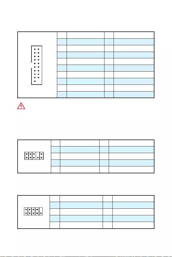
JUSB1~2: Connecteurs USB 2.0
Ces connecteurs vous permettent de relier des ports USB 2.0 sur le panneau avant.
1
2 10
9
1VCC 2VCC
3 USB0- 4 USB1-
5 USB0+ 6 USB1+
7 Ground 8 Ground
9 No Pin 10 NC
Important
y
Notez que les broches VCC et Terre doivent être branchées correctement afin
déviter tout dommage sur la carte mère.
y
Pour recharger votre tablette, smartphone ou autre périphérique par
lintermédiaire dun port USB, veuillez installer lutilitaire MSI® SUPER CHARGER.
12 Vue densemble des composants
JUSB3: Connecteur USB 3.1 Gen1
Ce connecteur vous permet de relier un port USB 3.1 Gen1 sur le panneau avant.
1
10 11
20
1Power 11 USB2.0+
2 USB3_RX_DN 12 USB2.0-
3 USB3_RX_DP 13 Ground
4 Ground 14 USB3_TX_C_DP
5 USB3_TX_C_DN 15 USB3_TX_C_DN
6 USB3_TX_C_DP 16 Ground
7 Ground 17 USB3_RX_DP
8 USB2.0- 18 USB3_RX_DN
9 USB2.0+ 19 Power
10 Ground 20 No Pin
Important
Notez que les câbles dalimentation et de terre doivent être branchés correctement
afin déviter dendommager la carte.
JAUD1: Connecteur audio avant
Ce connecteur se lie aux jacks audio du panneau avant.
1
2 10
9
1 MIC L 2 Ground
3 MIC R 4 NC
5 Head Phone R 6 MIC Detection
7 SENSE_SEND 8 No Pin
9 Head Phone L 10 Head Phone Detection
JCOM1: Connecteur de port série
Ce connecteur vous permet de relier un port série en option.
1
2 10
9
1 DCD 2 SIN
3 SOUT 4 DTR
5 Ground 6 DSR
7 RTS 8 CTS
9 RI 10 No Pin
13
Vue densemble des composants Vue densemble des composants
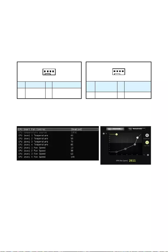
CPUFAN, SYSFAN1: Connecteurs pour ventilateurs
Les connecteurs pour ventilateurs peuvent être utilisés en mode PWM (Pulse Width
Modulation) et en mode tension. En mode PWM, les connecteurs fournissent une
sortie de 12V constante et ajustent la vitesse des ventilateurs avec un signal de
contrôle de vitesse. En mode tension, les connecteurs contrôlent la vitesse des
ventilateurs en modifiant la tension. Par conséquent, quand vous branchez un
ventilateur à 3 broches (Non-PWM) à un connecteur de ventilateur de mode PWM, la
vitesse sera toujours maintenue à 100% et cela occasionnera du bruit.
1
CPUFAN
1 Ground 2 +12V
3 Sense 4 Speed Control
Signal
1
SYSFAN1
1 Ground 2 Voltage
Control
3 Sense 4 NC
Connecteurs pour ventilateurs en mode PWM Connecteurs pour ventilateurs en mode tension
Contrôler la vitesse des ventilateurs
Il existe deux façons de gérer la vitesse des ventilateurs. La première est daller
dans le BIOS puis Advanced, et ensuite Hardware Monitor. La seconde est dutiliser
lapplication COMMAND CENTER.
COMMAND CENTER
Le sous-menu du BIOS Hardware Monitor vous permet dajuster la température et la
vitesse du ventilateur correspondante.
Lapplication COMMAND CENTER offre des points de gradient de la vitesse du
ventilateur qui vous permet dajuster la vitesse de ventilateur par rapport à la
température du processeur.
BIOS > Advanced > Hardware Monitor
14 Vue densemble des composants
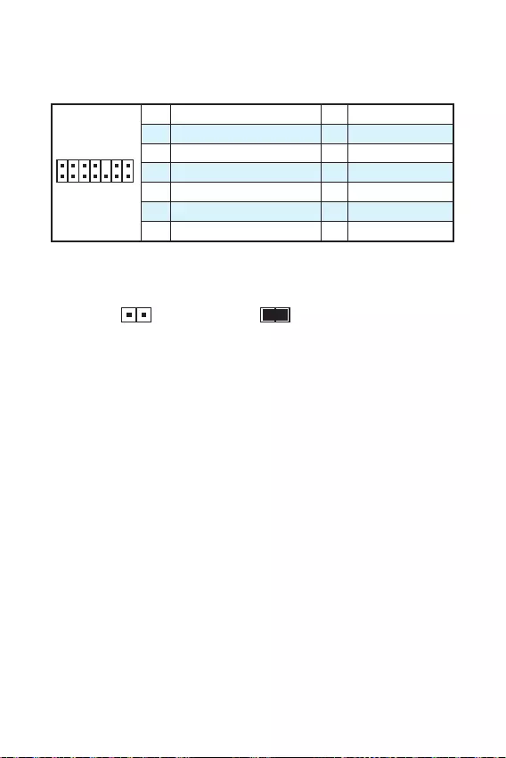
JTPM1: Connecteur de module TPM
Ce connecteur est relié à un module TPM (Trusted Platform Module). Veuillez vous
référer au manuel du module TPM pour plus dinformations.
1
2 14
13
1 LPC Clock 2 3V Standby power
3 LPC Reset 4 3.3V Power
5 LPC address & data pin0 6 Serial IRQ
7 LPC address & data pin1 8 5V Power
9 LPC address & data pin2 10 No Pin
11 LPC address & data pin3 12 Ground
13 LPC Frame 14 Ground
JCI1: Connecteur intrusion châssis
Ce connecteur est relié à un câble dinterrupteur intrusion châssis.
Normal
(défaut)
Commencer lactivité
intrusion châssis
Utilisation du détecteur dintrusion châssis
1. Reliez le connecteur JCI1 à linterrupteur ou au capteur dintrusion châssis situé
sur le boîtier du PC.
2. Fermez le couvercle du boîtier.
3. Allez dans le BIOS > Security (Sécurité) > Chassis Intrusion Configuration
(Configuration intrusion châssis).
4. Réglez Chassis Intrusion (Intrusion châssis) sur Enabled (Activé).
5. Appuyez sur F10 pour sauvegarder et quitter. Ensuite appuyez sur la touche
Entrée pour choisir Oui.
6. Désormais, si le boîtier du PC est ouvert quand lordinateur est allumé, vous
recevrez un message dalerte à lécran.
Réinitialisation de lalerte intrusion châssis
1. Allez dans le BIOS > Security (Sécurité) > Chassis Intrusion Configuration
(Configuration intrusion châssis).
2. Mettez Chassis Intrusion (Intrusion châssis) en Reset (Remettre).
3. Appuyez sur F10 pour sauvegarder et quitter. Ensuite appuyez sur la touche
Entrée pour choisir Oui.
15
Vue densemble des composants Vue densemble des composants
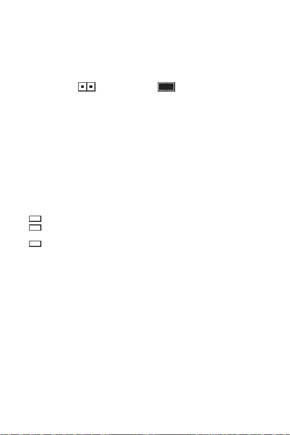
JBAT1: Cavalier clear CMOS (Réinitialisation BIOS)
Une mémoire CMOS est intégrée et est alimentée en externe par une batterie située
sur la carte mère afin de conserver les données de configuration système. Si vous
souhaitez nettoyer la configuration système, placez le cavalier sur Effacer CMOS de
manière à nettoyer la mémoire CMOS.
Conserver les
données
(défaut)
Effacer CMOS/
Réinitialiser BIOS
Réinitialiser le BIOS aux valeurs par défaut
1. Eteignez lordinateur et débranchez le câble dalimentation de la prise
électrique.
2. Utilisez un couvercle de cavalier pour fermer JBAT1 pour environ 5-10 secondes.
3. Enlevez le couvercle de cavalier du JBAT1.
4. Branchez de nouveau le câble dalimentation à votre ordinateur et allumez-le.
EZ Debug LED: Indicateurs LED Debug
Ces LED indiquent létat de la carte mère.
CPU — indique que le CPU nest pas détecté ou que son initialisation a échoué.
DRAM — indique que la mémoire DRAM nest pas détectée ou que son
initialisation a échoué.
VGA — indique que le GPU nest pas détecté ou que son initialisation a échoué.
16 Configuration du BIOS
Configuration du BIOS
Les réglages par défaut fournissent une performance optimale pour la stabilité du
système en conditions normales. Veillez à toujours garder les réglages par défaut
pour éviter dendommager le système ou tout problème au démarrage, sauf si vous
êtes familier avec le BIOS.
Important
y
Le BIOS est constamment mis à jour afin doffrir de meilleures performances
système. Par conséquent, la description peut différer selon la version de BIOS
utilisée et nest donc donnée quà titre de référence. Vous pouvez aussi vous
référer à longlet Help (Aide) pour obtenir la description des fonctions du BIOS.
y
Les photos ne sont données quà titre de référence et peuvent varier selon le
produit que vous achetez.
Entrer dans linterface Setup du BIOS
Pour entrer dans linterface Setup du BIOS, vous pouvez suivre ces deux méthodes :
yPendant le démarrage, lorsquapparaît le message Press DEL key to enter Setup
Menu, F11 to enter Boot Menu sur lécran, veuillez appuyer sur la touche Suppr.
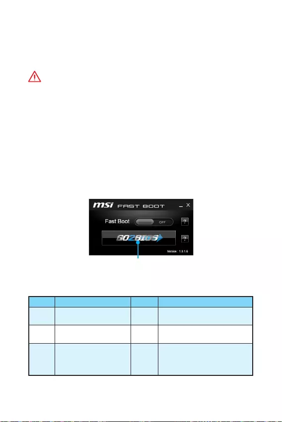
yQuand lordinateur est déjà en marche, vous pouvez utiliser lapplication MSI FAST
BOOT. Cliquez sur le bouton GO2BIOS puis sur OK. Le système redémarre et entre
dans linterface Setup du BIOS.
Cliquez sur GO2BIOS
Touches de fonction
Touche Fonction Touche Fonction
F1 Aide générale F4 Entrer dans le menu de réglages
du processeur
F5 Entrer dans le menu
Memory-Z F6 Réinitialiser avec paramètres
par défaut
F10 Sauvegarder les
modifications et réglages* F12
Prendre une capture décran
et la conserver dans le lecteur
flash USB (au format FAT/ FAT32
uniquement).
* Lorsque vous appuyez sur F10, une fenêtre de confirmation apparaît et fournit
linformation de modification. Choisissez entre Oui et Non pour confirmer.

17
Configuration du BIOS Configuration du BIOS
Réinitialiser le BIOS
Il se peut que vous ayez besoin de récupérer les réglages BIOS par défaut pour
résoudre des problèmes. Pour réinitialiser les réglages du BIOS, veuillez suivre lune
des méthodes suivantes :
yAllez dans le Setup du BIOS et appuyez sur F6 pour charger les réglages par défaut.
yEteignez votre machine. Mettez-la hors tension en appuyant sur le bouton au dos
de votre alimentation ou en débranchant le cordon de lalimentation. Placez le
cavalier Clear CMOS dans lautre position possible pendant quelques secondes,
puis remettez le en position dorigine.
Important
Veuillez vous référer à la section Cavalier Clear CMOS pour en savoir plus sur la
réinitialisation du BIOS.
Mettre le BIOS à jour
Mettre le BIOS à jour avec M-FLASH
Avant la mise à jour :
Veuillez télécharger la dernière version de BIOS compatible à votre carte mère sur le
site MSI. Ensuite, veuillez sauvegarder le nouveau BIOS sur le lecteur flash USB.
Mettre le BIOS à jour :
1. Connectez le lecteur Flash USB contenant le profil à lordinateur.
2. Appuyez sur la touche Suppr pour entrer dans linterface Setup du BIOS pendant
le processus de POST.
3. Allez dans le BIOS > M-FLASH > Select one file to update BIOS and ME,
choisissez un profil BIOS pour commencer la mise à jour du BIOS.
4. Une fois la mise à jour terminée, le système redémarrera.
Mettre le BIOS à jour avec Live Update 6
Avant la mise à jour :
Assurez-vous que le lecteur LAN est bien installé et que lordinateur est
correctement connecté à internet.
Mettre le BIOS à jour :
1. Installez et lancez MSI LIVE UPDATE 6.
2. Choisissez Manual scan (Scan manuel).
3. Vérifiez la boîte MB BIOS et cliquez sur le bouton Scan.
4. Choisissez le MB BIOS et cliquez sur licône pour télécharger et installer la
dernière version du BIOS.
5. Cliquez sur Suivant et choisissez le mode In Windows. Ensuite, cliquez sur Next
(Suivant) et Start (Commencer) pour lancer la mise à jour du BIOS.
6. Une fois la mise à jour terminée, le système redémarrera automatiquement.

18 Informations sur les logiciels
Informations sur les logiciels
Installer Windows® 7/ 8.1/ 10
1. Allumez lordinateur.
2. Insérez le disque de Windows® 7/ 8.1/ 10 dans le lecteur optique.
Remarque : Du fait des limites du chipset pendant linstallation de Windows® 7,
les lecteurs optiques USB et les clés USB ne seront pas supportés.
3. Appuyez sur le bouton Restart du boîtier de lordinateur.
4. Pour Windows® 8.1/ 10, ne prenez pas cette étape en compte. Pour Windows®
7, accédez au menu Advanced > Windows OS Configuration > Windows 7
Installation et passez le menu en [activé], sauvegardez les modifications et
redémarrez.
Remarque : It est conseillé de brancher le clavier USB/la souris USB au port USB
de gauche pendant linstallation du Windows® 7.
5. Appuyez sur la touche F11 pendant le POST (Power-On Self Test) du système
pour entrer dans le menu Boot Menu.
6. Choisissez le lecteur optique du Boot Menu.
7. Appuyez sur nimporte quelle touche lorsquapparaît le message (Press any key
to boot from CD or DVD).
8. Suivez les instructions à lécran pour installer Windows® 7/ 8.1/ 10.
Installer les pilotes
1. Allumez lordinateur sous Windows® 7/ 8.1/ 10.
2. Insérez le disque MSI® Driver dans le lecteur optique.
3. Loutil dinstallation apparaît automatiquement. Il trouvera et listera tous les
pilotes dont vous avez besoin.
4. Cliquez sur le bouton Install.
5. Linstallation des pilotes commence. Une fois terminée, il vous sera demandé de
redémarrer.
6. Cliquez sur le bouton OK pour terminer.
7. Redémarrez votre ordinateur.
Installer les utilitaires
Avant dinstaller les utilitaires, il faut compléter linstallation des pilotes.
1. Insérez le disque MSI® Driver dans le lecteur optique.
2. Loutil dinstallation apparaît automatiquement.
3. Cliquez sur longlet Utilities.
4. Choisissez les utilitaires que vous voulez installer.
5. Cliquez sur le bouton Install.
6. Linstallation des utilitaires commence. Une fois terminée, il vous sera demandé
de redémarrer.
7. Cliquez sur le bouton OK pour terminer.
8. Redémarrez votre ordinateur.
19
Informations sur les logiciels Informations sur les logiciels
MYSTIC LIGHY
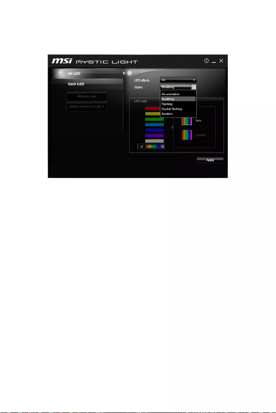
Lapplication MYSTIC LIGHT vous permet de contrôler les indicateurs LED sur votre
carte mère et votre ou vos cartes graphiques.
yToutes les LED — contrôle de tous les indicateurs LED sur votre carte mère et votre
ou vos cartes graphiques.
yChaque LED — contrôle de chaque indicateur LED de manière indépendante sur
votre carte mère et votre ou vos cartes graphiques.
yEffets LED — active ou désactive les différents effets de lumière des indicateurs
LED.
yStyles — permet de sélectionner les styles deffets de lumière offerts par les
indicateurs LED.
yCouleur des LED (en option) — permet de modifier la couleur des indicateurs LED.
Cette option dépend de la carte mère que vous avez achetée.
yBouton Appliquer — applique les paramètres choisis aux indicateurs LED.

20 Informations sur les logiciels
Contrôle de la ligne lumineuse dAudio Boost
yLe paramètre par défaut de la ligne lumineuse dAudio Boost est mis en mode
Breathing (Respiration) dans le BIOS.
yAprès avoir installé lapplication MYSTIC LIGHT et redémarré le système
dexploitation, le paramètre par défaut de la ligne lumineuse dAudio Boost
passera en mode No animation (Pas dillumination). Si vous modifiez le mode
dans lapplication MYSTIC LIGHT et cliquez sur Apply (Appliquer), le logiciel
reprogrammera immédiatement le mode dillumination dans le BIOS et le système
dexploitation.
Remarque : Le mode de la ligne
lumineuse dAudio Boost
passera en mode No
animation (Pas dillumination), si lutilisateur désactive lapplication MYSTIC LIGHT
dans le système dexploitation.
Important
y
Il est recommandé de contrôler le mode de la ligne lumineuse dAudio Boost par
lintermédiaire de lapplication MYSTIC LIGHT.
y
La ligne
lumineuse dAudio Boost
sera en mode Respiration dans le système
dexploitation lorsque vous sélectionnerez les modes suivants Flash, Double flash
et Aléatoire.

1
< 1> Inhalt
Inhalt
Sicherheitshinweis ……………………………………………………………………………… 2
Spezifikationen …………………………………………………………………………………… 3
Rückseite E/A ……………………………………………………………………………………..6
LAN Port LED Zustandstabelle ………………………………………………………………..6
Übersicht der Komponenten …………………………………………………………………7
CPU Sockel ……………………………………………………………………………………………8
DIMM-Steckplätze ………………………………………………………………………………….9
PCI_E1~3: PCIe Erweiterungssteckplätze …………………………………………………9
SATA1~4: SATA 6Gb/s Anschlüsse ………………………………………………………….10
JFP1, JFP2: Frontpanel-Anschlüsse ………………………………………………………10
JPWR1~2: Stromanschlüsse ………………………………………………………………….11
JUSB1~2: USB 2.0 Anschlüsse ………………………………………………………………11
JUSB3: USB 3.1 Gen1 Anschluss ……………………………………………………………12
JAUD1: Audioanschluss des Frontpanels ………………………………………………..12
JCOM1: Serieller Anschluss ………………………………………………………………….12
CPUFAN1, SYSFAN1: Stromanschlüsse für Lüfter ……………………………………13
JTPM1: TPM Anschluss …………………………………………………………………………14
JCI1: Gehäusekontaktanschluss …………………………………………………………….14
JBAT1: Steckbrücke zur CMOS-Löschung (Reset des BIOS) ……………………..15
EZ Debug LED: Debug LED-Anzeigen……………………………………………………..15
BIOS-Setup ……………………………………………………………………………………….16
Öffnen des BIOS Setups ………………………………………………………………………..16
Reset des BIOS …………………………………………………………………………………….17
Aktualisierung des BIOS ……………………………………………………………………….17
Softwarebeschreibung ………………………………………………………………………. 18
Installation von Windows® 7/ 8.1/ 10 ………………………………………………………18
Installation von Treibern ……………………………………………………………………….18
Installation von Utilities ………………………………………………………………………..18
MYSTIC LIGHT ……………………………………………………………………………………..19
Danke, dass Sie sich für das MSI® H110M PRO-VD PLUS/
H110M PRO-VH PLUS Motherboard entschieden haben.
Dieses Handbuch gibt informationen über Motherboard-Lay-
out, Komponentenübersicht, BIOS-Setup und Softwarein-
stallation.

2Sicherheitshinweis
Sicherheitshinweis
yDie im Paket enthaltene Komponenten sind der Beschädigung durch
elektrostatische Entladung (ESD). Beachten Sie bitte die folgenden Hinweise, um
die erfolgreichen Computermontage sicherzustellen.
yStellen Sie sicher, dass alle Komponenten fest angeschlossen sind. Lockere
Steckverbindungen können Probleme verursachen, zum Beispiel: Der Computer
erkennt eine Komponente nicht oder startet nicht.
yHalten Sie das Motherboard nur an den Rändern fest, und verhindern Sie die
Berührung der sensiblen Komponenten.
yUm eine Beschädigung der Komponenten durch elektrostatische Entladung
(ESD) zu vermeiden, sollten Sie eines elektrostatischen Armbands während
der Handhabung des Motherboards tragen. Wenn kein elektrostatischen
Handgelenkband vorhanden ist, sollten Sie Ihre statische Elektrizität ableiten,
indem Sie ein anderes Metallobjekt berühren, bevor Sie das Motherboard
anfassen.
yBewahren Sie das Motherboard in eine elektrostatische Abschirmung oder einem
Antistatiktuch, wenn das Motherboard nicht installiert ist.
yÜberprüfen Sie vor dem Einschalten des Computers, dass sich keine losen
Schrauben und andere Bauteile auf dem Motherboard oder im Computergehäuse
befinden.
yBitte starten Sie den Computer nicht, bevor die Installation abgeschlossen ist. Dies
könnte permanente Schäden an den Komponenten sowie zu das Verletzung des
Benutzers verursachen.
yBenötigen Sie Hilfe während des Installations benötigen, wenden Sie sich bitte an
einen zertifizierten Computer-Techniker.
ySchalten Sie die Stromversorgung aus und ziehen Sie das Netzleitung ab, bevor Sie
jegliche Computer-Komponente ein- und ausbauen.
yBewahren Sie die Bedienungsanleitung als künftige Referenz auf.
yHalten Sie das Motherboard von Feuchtigkeit fern.
yBitte stellen Sie sicher, dass Ihre Netzspannung den Hinweisen auf dem Netzteil
vor Anschluss des Netzteils an die Steckdose entspricht.
yVerlegen Sie das Netzkabel so, dass niemand versehentlich darauf treten kann.
Stellen Sie nichts auf dem Netzkabel ab.
yAlle Achtungs- und Warnhinweise auf dem Motherboard müssen befolgt werden.
yFalls einer der folgenden Umstände eintritt, lassen Sie bitte das Motherboard von
Kundendienstpersonal prüfen:
Flüssigkeit ist in dem Computer eingedrungen.
Das Motherboard wurde Feuchtigkeit ausgesetzt.
Das Motherboard funktioniert nicht richtig oder Sie können es nicht wie in der
Bedienungsanleitung beschrieben bedienen.
Das Motherboard ist heruntergefallen und beschädigt.
Das Motherboard weist offensichtlich Zeichen eines Schadens auf.
yNutzen und lagern Sie das Gerät nicht an Stellen, an denen Temperaturen von
mehr als 60C herrschen — das Motherboard kann in diesem Fall Schaden nehmen.
3
Sicherheitshinweis Spezifikationen
Spezifikationen
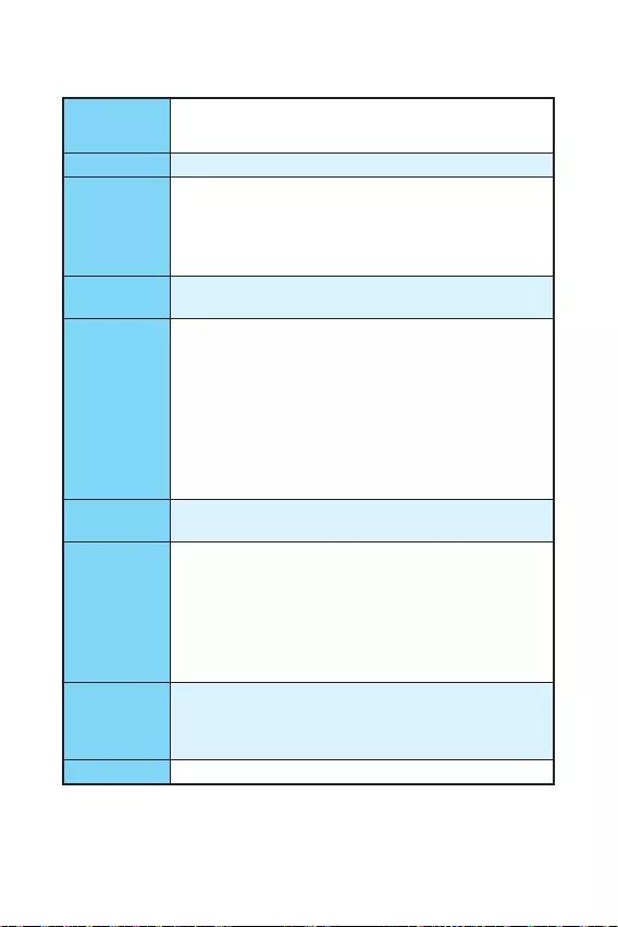
CPU
Unterstützt Intel® Core™ i3/i5/i7 der 6. Generation Prozessoren,
und Intel® Pentium® und Celeron® Prozessoren für Sockel
LGA1151
Chipsatz yIntel® H110 Chipsatz
Speicher
y2x DDR4 Speicherplätze, aufrüstbar bis 32GB
Unterstützt DDR4 2133 MHz
yDual-Kanal-Speicherarchitektur
yUnterstützt ungepufferte non-ECC-Speicher E
yUnterstützt Intel® Extreme Memory Profile (XMP)
Erweiterung-
anschlüsse
y1x PCIe 3.0 x16Unterstützt
y2x PCIe 2.0×1-Steckplätze
Onboard-Grafik
yH110M PRO-VH PLUS
1x VGA Anschluss, unterstützt eine maximale Auflösung von
2048×1536@50Hz, 2048×1280@60Hz, 1920×1200@60Hz
1x HDMI™ Anschluss, unterstützt eine maximale Auflösung
von 4096×2160@24Hz, 2560×1600@60Hz
yH110M PRO-VD PLUS
1x VGA Anschluss, unterstützt eine maximale Auflösung von
2048×1536@50Hz, 2048×1280@60Hz, 1920×1200@60Hz
1x DVI-D Anschluss, unterstützt eine maximale Auflösung
von 1920×1200@60Hz
Aufbewahrung Intel® H110 Chipsatz
y4x SATA 6Gb/s Anschlüsse
USB
yIntel® H110 Chipsatz
4x USB 3.1 Gen1 (SuperSpeed USB) Anschlüsse (2
Anschlüsse an der rückseitigen Anschlussleiste, 2
Anschlüsse stehen durch die internen USB Anschluss zur
Verfügung)
6x USB 2.0 (High-speed USB) Anschlüsse (2 Anschlüsse an
der rückseitigen Anschlussleiste, 4 Anschlüsse stehen durch
die internen USB Anschluss zur Verfügung)
Audio
yRealtek® ALC887 Codec
y7,1-Kanal-HD-Audio*
* Für den 7,1-Kanal-Audio Ausgang benötigen Sie das HD-
Audio-Modul an der Frontseite des Gehäuses.
LAN 1x Realtek® RTL8111H Gigabit LAN Controller
Fortsetzung auf der nächsten Seite

4Spezifikationen
Fortsetzung der vorherigen Seite
Hintere Ein-/
und Ausgänge
yPS/2 Tastatur-Anschluss x1
yPS/2 Maus-Anschluss x1
yUSB 3.1 Gen1 Anschlüsse x2
yHDMI™ Anschluss x1 (H110M PRO-VH PLUS)
yDVI-D Anschluss x1 (H110M PRO-VD PLUS)
yVGA Anschluss x1
yLAN (RJ45) Anschluss x1
yUSB 2.0 Anschlüsse x2
yAudiobuchsen x3
Interne
Anschlüsse
yATX 24-poliger Stromanschluss x1
yATX 12V 4-poliger Stromanschluss x1
ySATA 6Gb/s Anschlüsse x4
yUSB 2.0 Anschlüsse x2 (unterstützt zusätzliche 4 USB
2.0-Ports)
yUSB 3.1 Gen1 Anschluss x1 (unterstützt zusätzliche 2 USB 3.1
Gen1-Ports)
y4-poliger CPU-Lüfter-Anschluss x1
y4-poliger System-Lüfter-Anschluss x1
yAudioanschluss des Frontpanels x1
yFrontpanel-Anschlüsse x2
yTPM Anschluss x1
ySerieller Anschluss x1
yGehäusekontaktschalter x1
ySteckbrücke zur CMOS-Löschung x1
E/A Anschluss NUVOTON NCT5563D Controller Chip
Hardware
Monitor
yCPU/System Temperaturerfassung
yCPU/System Geschwindigkeitserfassung
yCPU/System Lüfterdrehzahlregelung
Formfaktor yMicro-ATX Formfaktor
y8,9 Zoll x 6,8 Zoll (22,6 cm x 17,3 cm)
BIOS
Funktionen
y1x 64 Mb Flash
yUEFI AMI BIOS
yACPI 5.0, PnP 1.0a, SM BIOS 2.8
yMehrsprachenunterstützung
Fortsetzung auf der nächsten Seite

5
Spezifikationen Spezifikationen
Fortsetzung der vorherigen Seite
Software
yTreiber
yCOMMAND CENTER
yLIVE UPDATE 6
yFAST BOOT
ySUPER CHARGER
yM-CLOUD
yRAMDISK
yIntel® Small Business Basics
yNETWORK GENIE
yIntel® Extreme Tuning Utility
yNorton™ Security
yGoogle Chrome™, Google Toolbar, Google Drive
yCPU-Z
yMYSTIC LIGHT
MSI Exklusive
Merkmale
yCLICK BIOS
yCOMMAND CENTER
yRAMDISK
ySURPER CHARGER
yFAST BOOT
yLIVE UPDATE 6
yM-CLOUD
yMYSTIC LIGHT
6Rückseite E/A
Rückseite E/A
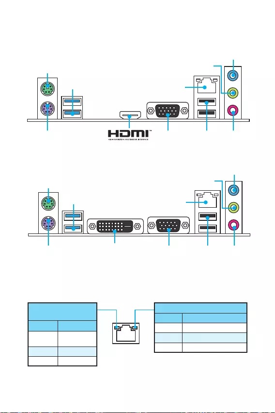
DVI-D
H110M PRO-VD PLUS
PS/2 Maus
LAN
USB 3.1 Gen1
USB 2.0
VGAPS/2
Tastatur
H110M PRO-VH PLUS Line-In
Line-Out
Mic In
Verbindung/ Aktivität
LED
Zustand Bezeichnung
Aus Keine
Verbindung
Gelb Verbindung
Blinkt Datenaktivität
Geschwindigkeit LED
Zustand Bezeichnung
Aus 10 Mbps-Verbindung
Grün 100 Mbps-Verbindung
Orange 1 Gbps-Verbindung
LAN Port LED Zustandstabelle
PS/2 Maus
LAN
USB 3.1 Gen1
VGAPS/2
Tastatur
Line-In
Line-Out
USB 2.0 Mic In
7
Rückseite E/A Übersicht der Komponenten
BAT1
DVI- D(optional)
HDMI(optional)
CPUFAN
JPWR2
PCI_E1
PCI_E2
PCI_E3
DIMM1
SYSFAN1
DIMM2
JUSB3
JFP1
JUSB1
SATA1
JFP2
JUSB2
JPWR1
EZ Debug LED
JCI1
SATA2
SATA3
SATA4
JTPM1
JBAT1
JCOM1
CPU Sockel
Übersicht der Komponenten
JAUD1
8Übersicht der Komponenten
CPU Sockel
Installieren Sie bitte die CPU in den CPU Sockel, wie unten aufgezeigt.
Wichtig
y
Ziehen Sie das Netzkabel ab, bevor Sie CPU ein- und ausbauen.
y
Bitte bewahren Sie die CPU Schutzkappe nach der Installation des Prozessors auf.
MSI wird RMA (Return Merchandise Authorization) Anfragen nur dann behandeln,
wenn die Schutzklappe auf dem CPU-Sockel des Motherboards sitzt.
y
Wenn Sie eine CPU einbauen, denken sie bitte daran, einen CPU-Kühler zu
installieren. Ein CPU-Kühlkörper ist notwendig, um eine Überhitzung zu vermeiden
und die Systemstabilität zu gewährleisten.
y
Stellen Sie sicher, dass Ihr Kühlkörper eine feste Verbindung mit der CPU
hergestellt hat, bevor Sie Ihr System starten.
y
Überhitzung beschädigt die CPU und das System nachhaltig. Stellen Sie stets eine
korrekte Funktionsweise des CPU Kühlers sicher, um die CPU vor Überhitzung zu
schützen. Stellen Sie sicher, dass eine gleichmäßige Schicht der thermischen Paste
zwischen der CPU und dem Kühlkörper vorhanden ist, um die Wärmeableitung zu
erhöhen.
y
Schützen Sie den CPU-Sockel immer mit der Plastikabdeckung, wenn keine CPU
installiert ist.
y
Verwenden Sie bitte die Installationsanweisung des Kühlkörper/ Kühlers, falls Sie
eine seperate CPU oder Kühlkörper/ Kühler erworben haben.
1
4
6
5
78
9
3
2
9
Übersicht der Komponenten Übersicht der Komponenten
DIMM-Steckplätze
Setzen Sie bitte ein Speichermodul wie untern gezeigt in den DIMM-Steckplatz ein.
Wichtig
y
Aufgrund der Chipsatzressourcennutzung wird die verfügbare Kapazität des
Speichers kleiner sein als die Größe der installierten Speicherkapazität.
y
Bitte beachten Sie, dass die maximale Kapazität eines 32-Bit-Windows-
Betriebssystem bei 4GB oder weniger liegt. Wenn Sie mehr als 4 GB Speicher auf
dem Motherboard einbauen möchten, empfehlen wir deshalb, ein 64-Bit-Windows-
Betriebssystem zu installieren.
PCI_E1~3: PCIe Erweiterungssteckplätze
BAT1
DVI- D(optional)
HDMI(optional)
PCI_E1: PCIe 3.0 x16-Steckplatz
PCI_E2: PCIe 2.0×1-Steckplatz
PCI_E3: PCIe 2.0×1-Steckplatz
Wichtig
Achten Sie darauf, dass Sie den Strom abschalten und das Netzkabel aus der
Steckdose herausziehen, bevor Sie eine Erweiterungskarte installieren oder
entfernen. Lesen Sie bitte auch die Dokumentation der Erweiterungskarte, um
notwendige zusätzliche Hardware oder Software-Änderungen zu überprüfen.
1
12
3
3
2
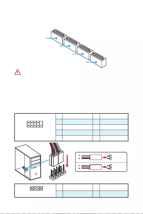
10 Übersicht der Komponenten
SATA1~4: SATA 6Gb/s Anschlüsse
Diese Anschlüsse basieren auf der Hochgeschwindigkeitsschnittstelle SATA 6Gb/s.
Pro Anschluss kann ein SATA Gerät angeschlossen werden.
SATA3
SATA2
SATA4
SATA1
Wichtig
y
Knicken Sie das SATA-Kabel nicht in einem 90 Winkel. Datenverlust könnte die
Folge sein.
y
SATA-Kabel haben identische Stecker an beiden Enden. Es wird empfohlen den
flachen Stecker auf dem Motherboard einstecken.
JFP1, JFP2: Frontpanel-Anschlüsse
Diese Anschlüsse verbinden mit den Schaltern und LEDs auf des Frontpanels.
1
2 10
9
JFP1
1 HDD LED + 2 Power LED +
3 HDD LED — 4 Power LED —
5 Reset Switch 6 Power Switch
7 Reset Switch 8 Power Switch
9 Reserved 10 No Pin
1
JFP2
1 Speaker — 2 Buzzer +
3 Buzzer — 4 Speaker +
HDD LED
RESET SW
HDD LED HDD LED —
HDD LED +
POWER LED —
POWER LED +
POWER LED
JFP1
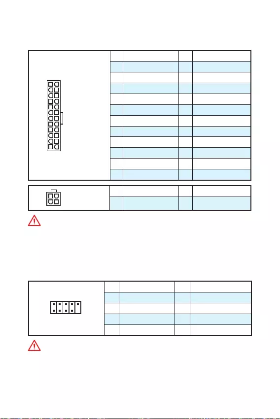
11
Übersicht der Komponenten Übersicht der Komponenten
JPWR1~2: Stromanschlüsse
Mit diesen Anschlüssen verbinden Sie die ATX Stromstecker.
24
131
12
JPWR1
1 +3.3V 13 +3.3V
2 +3.3V 14 -12V
3 Ground 15 Ground
4 +5V 16 PS-ON#
5 Ground 17 Ground
6 +5V 18 Ground
7 Ground 19 Ground
8 PWR OK 20 Res
9 5VSB 21 +5V
10 +12V 22 +5V
11 +12V 23 +5V
12 +3.3V 24 Ground
3
2 1
4JPWR2
1 Ground 3 +12V
2 Ground 4 +12V
Wichtig
Stellen Sie sicher, dass alle Anschlüsse mit den richtigen Anschlüssen des Netzteils
verbunden sind, um einen stabilen Betrieb der Hauptplatine sicherzustellen.
JUSB1~2: USB 2.0 Anschlüsse
Mit diesen Anschlüssen können Sie die USB 2.0 Anschlüsse auf dem Frontpanel
verbinden.
1
2 10
9
1VCC 2VCC
3 USB0- 4 USB1-
5 USB0+ 6 USB1+
7 Ground 8 Ground
9 No Pin 10 NC
Wichtig
y
Bitte beachten Sie, dass Sie die mit VCC (Stromführende Leitung) und Ground
(Erdleitung) bezeichneten Pins korrekt verbinden müssen, ansonsten kann es zu
Schäden kommen.
y
Um das iPad, iPhone und iPod über USB-Anschlüsse aufzuladen, installieren Sie
bitte die MSI® SUPER CHARGER Software.
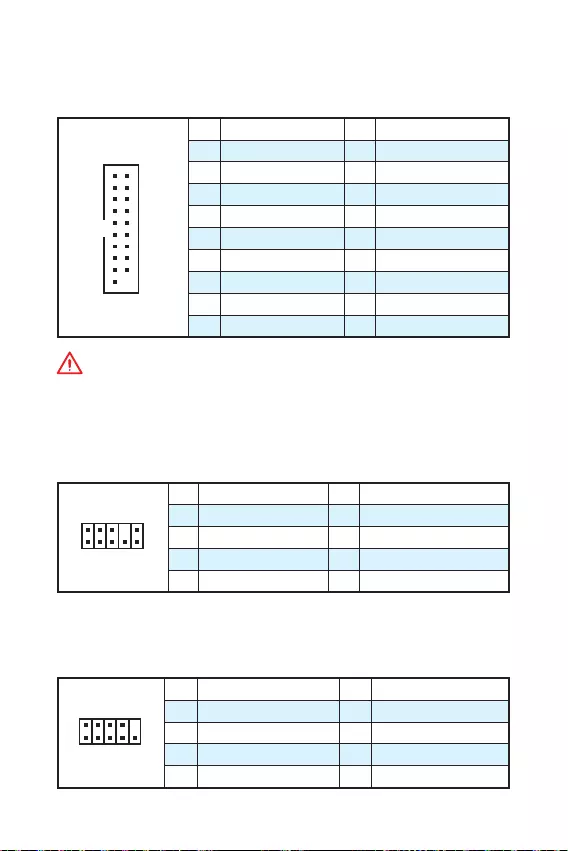
12 Übersicht der Komponenten
JUSB3: USB 3.1 Gen1 Anschluss
Mit diesem Anschluss können Sie den USB 3.1 Gen1 Anschluss auf dem Frontpanel
verbinden.
1
10 11
20
1Power 11 USB2.0+
2 USB3_RX_DN 12 USB2.0-
3 USB3_RX_DP 13 Ground
4 Ground 14 USB3_TX_C_DP
5 USB3_TX_C_DN 15 USB3_TX_C_DN
6 USB3_TX_C_DP 16 Ground
7 Ground 17 USB3_RX_DP
8 USB2.0- 18 USB3_RX_DN
9 USB2.0+ 19 Power
10 Ground 20 No Pin
Wichtig
Bitte beachten Sie, dass Sie die mit Stromführende Leitung und Erdleitung
bezeichneten Pins korrekt verbinden müssen, ansonsten kann es zu Schäden
kommen.
JAUD1: Audioanschluss des Frontpanels
Dieser Anschluss ermöglicht den Anschluss von Audiobuchsen eines Frontpanels.
1
2 10
9
1 MIC L 2 Ground
3 MIC R 4 NC
5 Head Phone R 6 MIC Detection
7 SENSE_SEND 8 No Pin
9 Head Phone L 10 Head Phone Detection
JCOM1: Serieller Anschluss
Mit diesem Anschluss können Sie das optionale serielle Schnittstelle mit dem
Einbausatze verbinden.
1
2 10
9
1 DCD 2 SIN
3 SOUT 4 DTR
5 Ground 6 DSR
7 RTS 8 CTS
9 RI 10 No Pin
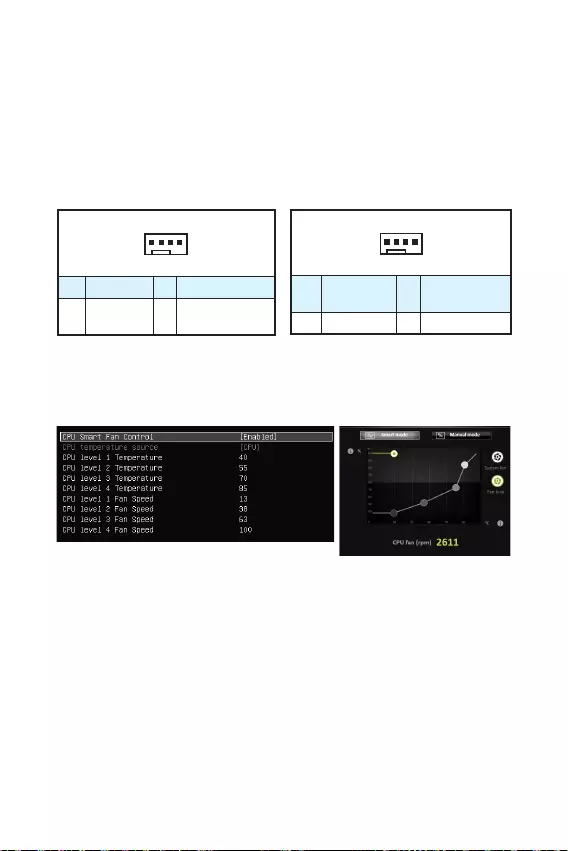
13
Übersicht der Komponenten Übersicht der Komponenten
CPUFAN1, SYSFAN1: Stromanschlüsse für Lüfter
Diese Anschlüsse können im PWM (Pulse Width Modulation) Modus oder
Spannungsmodus betrieben werden. Im PWM-Modus bieten die Lüfteranschlüsse
konstante 12V Ausgang und regeln die Lüftergeschwindigkeit per
Drehzahlsteuersignal. Im Spannungsmodus bestimmen die Lüfteranschlüsse die
Lüftergeschwindigkeit durch Ändern der Spannung. Wenn Sie ein 3-Pin (Non-PWM)
Lüfter an einen PWM-Modus Lüfteranschluss anschließen, läuft der Lüfter mit
höchster Drehzahl und kann unangenehm laut werden.
1
CPUFAN
1 Ground 2 +12V
3 Sense 4 Speed Control
Signal
1
SYSFAN1
1 Ground 2 Voltage
Control
3 Sense 4 NC
Lüfteranschluss des PWM-Modus Lüfteranschluss des Spannung-Modus
Lüfterdrehzahl steuern
Es gibt zwei Möglichkeiten zur Steuerung der Lüfterdrehzahl. Sie können unter BIOS
> Advanced > Hardware Monitor die Drehzahl ändern oder die COMMAND CENTER
Anwendung verwenden.
COMMAND CENTER
BIOS Hardware Monitor Untermenü ermöglicht es, eine Temperaturwerte und die
entsprechenden Lüfterstufen einzustellen.
COMMAND CENTER benutzt einen Graphen, mit dem man die Lüfterdrehzahl im
Bezug auf die CPU-Temperatur anpassen kann.
BIOS > Advanced > Hardware Monitor
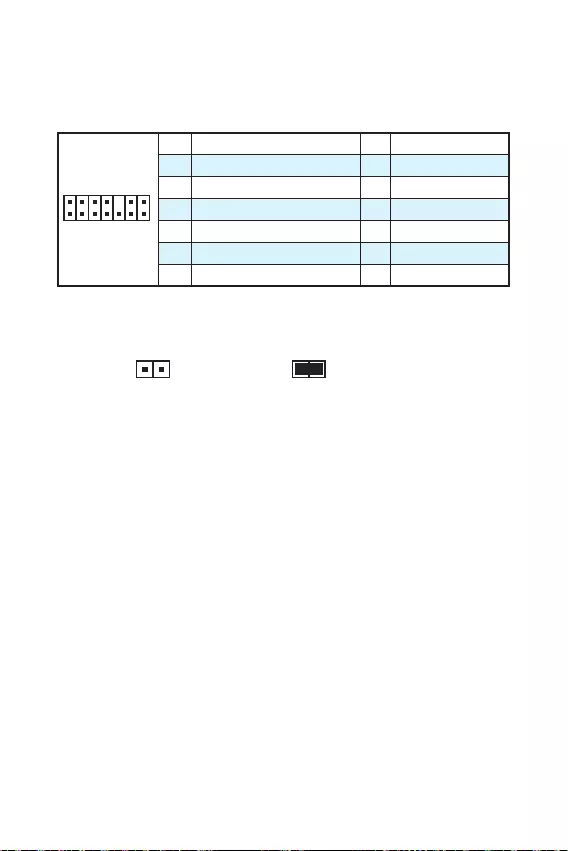
14 Übersicht der Komponenten
JTPM1: TPM Anschluss
Dieser Anschluss wird für das TPM Modul (Trusted Platform Module) verwendet.
Weitere Informationen über den Einsatz des optionalen TPM Modules entnehmen Sie
bitte dem TPM Plattform Handbuch.
1
2 14
13
1 LPC Clock 2 3V Standby power
3 LPC Reset 4 3.3V Power
5 LPC address & data pin0 6 Serial IRQ
7 LPC address & data pin1 8 5V Power
9 LPC address & data pin2 10 No Pin
11 LPC address & data pin3 12 Ground
13 LPC Frame 14 Ground
JCI1: Gehäusekontaktanschluss
Dieser Anschluss wird mit einem Kontaktschalter verbunden.
Normal
(Standardwert)
Trigger Gehäusekontakt
Event
Gehäusekontakt-Detektor verwenden
1. Schließen Sie den JCI1-Anschluss am Gehäusekontakt-Schalter/ Sensor am
Gehäuse an.
2. Schließen Sie die Gehäuseabdeckung.
3. Gehen Sie zu BIOS > Security > Chassis Intrusion Configuration.
4. Stellen Sie Chassis Intrusion auf Enabled.
5. Drücken Sie F10 zum Speichern und Beenden und drücken Sie dann die Enter—
Taste, um Ja auszuwählen.
6. Bei eingeschaltetem Computer wird eine Warnmeldung auf dem Bildschirm
angezeigt, wenn die Gehäuseabdeckung wieder geöffnet wird.
Gehäusekontakt-Warnung zurücksetzen
1. Gehen Sie zu BIOS > Security > Chassis Intrusion Configuration.
2. Stellen Sie Chassis Intrusion auf Reset.
3. Drücken Sie F10 zum Speichern und Beenden und drücken Sie dann die Enter—
Taste, um Ja auszuwählen.
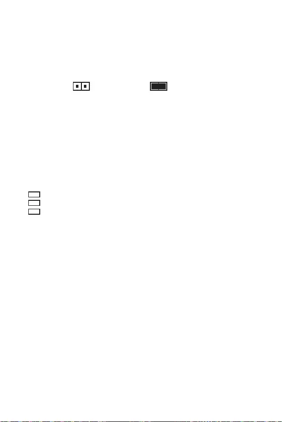
15
Übersicht der Komponenten Übersicht der Komponenten
JBAT1: Steckbrücke zur CMOS-Löschung (Reset des
BIOS)
Der Onboard CMOS Speicher (RAM) wird durch eine externe Spannungsversorgung
durch eine Batterie auf dem Motherboard versorgt, um die Daten der
Systemkonfiguration zu speichern. Wenn Sie die Systemkonfiguration löschen wollen,
müssen Sie die Steckbrücke für kurze Zeit umsetzen.
Daten beibehalten
(Standardwert)
CMOS-Daten löschen/
Reset des BIOS
Rücksetzen des BIOS auf Standardwerte
1. Schalten Sie den Computer ab und ziehen Sie das Netzkabel ab.
2. Schließen Sie JBAT1 mit dem Deckel zur CMOS-Löschung für ca. 5-10 Sekunden.
3. Entfernen Sie den Deckel von JBAT1.
4. Stecken Sie das Kabel Ihres Computers in die Steckdose hinein und schalten Sie
den Computer ein.
EZ Debug LED: Debug LED-Anzeigen
Diese LEDs zeigen den Status des Motherboards an.
CPU — CPU wird nicht erkannt oder ist fehlerhaft.
DRAM — DRAM wird nicht erkannt oder ist fehlerhaft.
VGA — GPU wird nicht erkannt oder ist fehlerhaft.
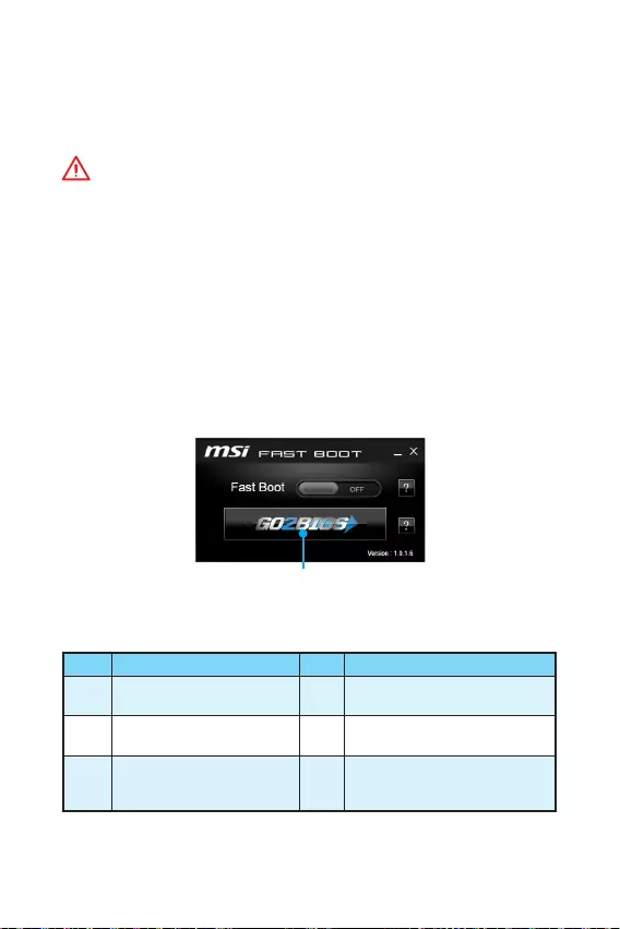
16 BIOS-Setup
BIOS—Setup
Die Standardeinstellungen bieten die optimale Leistung für die Systemstabilität unter
Normalbedingungen. Sie sollten immer die Standardeinstellungen behalten, um
mögliche Schäden des Systems oder Boot-Fehler zu vermeiden, außer Sie besitzen
ausreichende BIOS Kenntnisse.
Wichtig
y
BIOS Funktionen werden kontinuierlich aktualisiert für eine bessere
Systemleistung. Deswegen können die Beschreibungen leicht von der letzten
Fassung des BIOS abweichen und sollten demnach nur als Anhaltspunkte dienen.
Für eine Beschreibung der BIOS Funktionen rufen Sie die HELP Informationstafel
aus.
y
Die Bilder in diesem Kapitel sind nur als Referenz und können von dem von Ihnen
erworbenen Produkt abweichen.
Öffnen des BIOS Setups
Befolgen Sie bitte die nachfolgende Schritten, um das BIOS Setup aufzurufen.
yWährend des BOOT-Vorgangs drücken Sie die Taste Delete, wenn die Meldung
Press DEL key to enter Setup Menu, F11 to enter Boot Menu erscheint.
yVerwenden Sie die MSI FAST BOOT Anwendung. Klicken Sie die GO2BIOS-Taste und
drücken OK. Das System startet neu und geht direkt ins BIOS.
Klicken Sie auf GO2BIOS
Funktionstasten
Taste Funktion Taste Funktion
F1 Allgemeine Hilfe F4 Öffnen das CPU-Spezifikationen-
Menü
F5 Öffnen das Memory-Z-Menü F6 Laden der ursprünglichen Setup-
Standardwerte
F10 Speichern oder Zurücksetzen
der Änderungen* F12
Machen einen Screenshot und
speichern auf einen FAT/ FAT32-
USB-Laufwerk.
* Beim Drücken der F10 Taste wird das Fenster zum Speichern der Einstellungen
angezeigt. Wählen Sie Yes, um die Wahl zu bestätigen, oder No, um die derzeitige
Einstellung beizubehalten.

17
BIOS-Setup BIOS-Setup
Reset des BIOS
Sie können die Werkseinstellung wieder herstellen, um bestimmte Probleme zu
lösen. Es gibt verschiedene Möglichkeiten, um das BIOS zurückzusetzen:
yÖffnen Sie das BIOS und drücken Sie F6, um optimierten Voreinstellungen zu laden.
ySchließen Sie die Clear CMOS Steckbrücke auf dem Motherboard.
Wichtig
Bitte lesen Sie für Informationen zum BIOS-Reset im Bereich „Steckbrücke zur
CMOS-Löschung nach.
Aktualisierung des BIOS
Aktualisierung des BIOS mit dem M-FLASH-Programm
Vorbereitung:
Laden Sie bitte die neueste BIOS Version, die dem Motherboard-Modell entspricht,
von der offiziellen MSI Website herunter und speichern Sie die BIOS-Datei auf USB-
Flash-Laufwerk.
BIOS-Aktualisierungsschritte:
1. Schließen das USB-Flashlaufwerk mit der BIOS-Datei an den Computer.
2. Starten Sie das System neu und drücken Sie während des POST-Vorgangs die
Taste Del (Entf), um das BIOS zu öffnen.
3. Gehen Sie zu BIOS > M-FLASH > Select one file to update BIOS and ME. Wählen
Sie die BIOS-Datei zur Durchführung des BIOS-Aktualisierungsprozesses aus.
4. Nachdem das Flashen des BIOS vollständig ist, startet das System automatisch
neu.
Aktualisierung des BIOS mit Live Update 6
Vorbereitung:
Stellen Sie sicher, dass zuvor die LAN-Treiber installiert wurden und eine
Internetverbindung eingerichtet ist.
BIOS-Aktualisierungsschritte:
1. Installieren und starten Sie „MSI LIVE UPDATE 6.
2. Wählen Sie Manual scan aus.
3. Machen Sie ein Häkchen bei MB BIOS und klicken sie auf die Scan Taste.
4. Wählen Sie MB BIOS aus und klicken auf dieses Icon , um die neueste BIOS-
Datei zu laden und zu installieren.
5. Klicken Sie auf Next (Weiter) und wählen Sie In Windows mode aus. Und klicken
dann auf Next (Weiter) und Start (Starten), um das BIOS-Update zu starten.
6. Nachdem das Flashen des BIOS vollständig ist, startet das System automatisch
neu.

18 Softwarebeschreibung
Softwarebeschreibung
Installation von Windows® 7/ 8.1/ 10
1. Schalten Sie den Computer ein.
2. Legen Sie die Windows® 7/ 8.1/ 10 Disk in das optisches Laufwerk.
Hinweis: Auf Grund einer Chipsatz-Limitierung werden während des Windows®
7 Installationsprozesses keine optischen Laufwerke und USB-Laufwerke oder
USB-Sticks unterstützt.
3. Drücken Sie die Taste Restart auf dem Computergehäuse.
4. Für Windows 8.1/ 10, überspringen Sie diesen Schritt. Für Windows 7, gehen Sie
ins BIOS-Menü: Advanced > Windows OS Configuration > Windows 7 Installation
und aktivieren Sie die Punkte, um die Änderungen zu speichern und starten Sie
den Computer neu.
Hinweis: Wir empfehlen Ihnen, dass Sie Ihren USB-Tastatur/ USB-Maus an den
linken USB-Anschluss bei der Installation von Windows 7 anschließen.
5. Drücken Sie die F11-Taste während des POST-Vorgangs (Power-On Self Test), um
das Bootmenu zu öffnen.
6. Wählen Sie das optische Laufwerk aus dem Bootmenu.
7. Wenn eine entsprechende Meldung Press any key to boot from CD or DVD…
angezeigt wird, drücken Sie eine beliebige Taste.
8. Folgen Sie den Anweisungen auf dem Bildschirm, um das Dienstprogramm
„Windows® 7/ 8.1/ 10 zu installieren.
Installation von Treibern
1. Starten Sie Ihren Computer mit Windows® 7/ 8.1/ 10.
2. Legen Sie die MSI® Treiber Disk in das optisches Laufwerk.
3. Der Installer wird automatisch erscheint und findet und finden Sie die benötigten
Treiber in die Liste.
4. Klicken Sie auf Install.
5. Die Software-Installation ist im Gange. Wenn die Installation abgeschlossen ist,
werden Sie dazu aufgefordet, den Computer neu zu starten.
6. Klicken Sie auf OK zum Beenden.
7. Starten Sie Ihren Computer neu.
Installation von Utilities
Bevor Sie Anwendungen installieren, müssen Sie die Treiber-Installation vollständig
beendet haben.
1. Legen Sie die MSI® Treiber Disk in das optisches Laufwerk.
2. Der Installer wird automatisch erscheint.
3. Klicken Sie auf Utilities.
4. Wählen Sie die Dienstprogramme, die installiert werden soll.
5. Klicken Sie die Taste Install.
6. Die Utilities-Installation ist im Gange. Wenn die Installation abgeschlossen ist,
werden Sie dazu aufgefordet, den Computer neu zu starten.
7. Klicken Sie auf OK zum Beenden.
8. Starten Sie Ihren Computer neu.
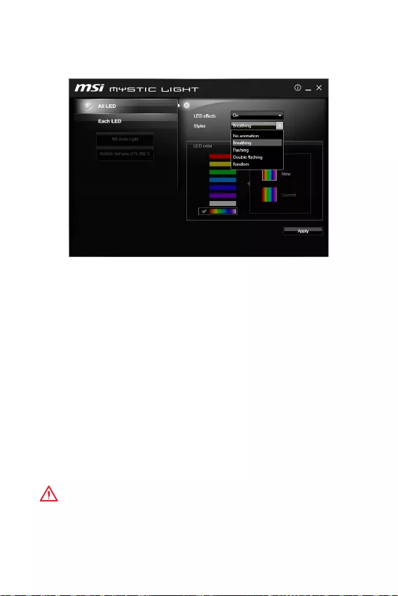
19
Softwarebeschreibung Softwarebeschreibung
MYSTIC LIGHT
MYSTIC LIGHT ermöglicht Ihnen die Steuerung der LED-Beleuchtung des
Motherboards und der Grafikkarten.
yAlle LEDs (All LED) — Steuert alle LEDs auf dem Motherboard und den
Grafikkarten.
yJede LED (Each LED) — Jede LED-Segment auf dem Mainboard und der Grafikkarte
wird getrennt gesteuert.
yLED-Effekte (LED effects) — Schaltet die LEDs ein- bzw. aus.
yModi (Styles) — Wählt den LED-Stil aus der Dropdown-Liste.
yLED Farbe (LED colors, optional) — Ermöglicht das Ändern der LED Farbe. Diese
Option hängt von dem eingesetzten Motherboard ab.
y Anwenden (Apply) — Aktiviert die gewählten LED-Einstellungen.
Die Steuerung des Audio-Line-Beleuchtung
yDie Standardeinstellung der Audio-Line-Beleuchtung im BIOS ist „Breathing.
yNach der Installation von MYSTIC LIGHT und dem Neustart des Systems schaltet
der voreingestellte Audio-Line-Modus in die Variante „Ohne Animation um. Wenn
Sie die Audio-Line-Beleuchtung in MYSTIC LIGHT ändern und anschließend die
Änderungen bestätigen, wird die Software sowohl die Einstellungen im BIOS als
auch auf Betriebssystemebene unmittelbar umstellen.
Hinweis: Wenn der Benutzer MYSTIC LIGHT im Betriebssystem deaktiviert, wird der
Audio-Line-Modus in Ohne Animation umgestellt.
Wichtig
y
Es wird empfohlen, den Audio-Line-Modus mit der MYSTIC LIGHT-Applikation zu
steuern.
y
Wenn Sie einen der folgenden Modi wählen, wie Flashing, Double Flashing und
Random, wird unter DOS der „Breathing-Modus eingestellt.

20 Anmerkung
Anmerkung

1
< 1>
Содержание
Безопасное использование продукции ………………………………………………. 2
Технические характеристики ……………………………………………………………..3
Задняя панель ввода/ вывода ……………………………………………………………. 6
Таблица состояния индикатора порта LAN ……………………………………………..6
Компоненты материнской платы ………………………………………………………..7
Процессорный сокет ……………………………………………………………………………..8
Слоты DIMM ………………………………………………………………………………………….9
PCI_E1~3: Слот расширения PCIe …………………………………………………………..9
SATA1~4: Разъемы SATA 6 Гб/с …………………………………………………………….10
JFP1, JFP2: Разъемы передней панели ………………………………………………..10
JPWR1~2: Разъемы питания ………………………………………………………………..11
JUSB1~2: Разъемы USB 2.0 ………………………………………………………………….11
JUSB3: Разъем USB 3.1 Gen1 ……………………………………………………………….12
JAUD1: Разъем аудио передней панели ……………………………………………….12
JCOM1: Разъем последовательного порта …………………………………………….12
CPUFAN, SYSFAN1: Разъемы вентиляторов …………………………………………..13
JTPM1: Разъем модуля ТРМ …………………………………………………………………14
JCI1: Разъем датчика открытия корпуса ……………………………………………….14
JBAT1: Джампер очистки данных CMOS (Сброс BIOS) ……………………………15
EZ Debug LED: Индикатор отладки ……………………………………………………….15
Настройка BIOS …………………………………………………………………………………16
Вход в настройки BIOS ………………………………………………………………………..16
Сброс BIOS ………………………………………………………………………………………….17
Обновление BIOS ………………………………………………………………………………..17
Описание программного обеспечения ……………………………………………….18
Установка Windows® 7/ 8.1/ 10 ……………………………………………………………..18
Установка драйверов …………………………………………………………………………..18
Установка утилит …………………………………………………………………………………18
MYSTIC LIGHT ……………………………………………………………………………………..19
Благодарим Вас за покупку материнской платы MSI®
H110M PRO-VD PLUS/ H110M PRO-VH PLUS. Данное
руководство пользователя содержит информацию о схеме
платы, компонентах материнской платы и настройке BIOS.

2
Безопасное использование продукции
yКомпоненты, входящие в комплект поставки могут быть повреждены
статическим электричеством. Для успешной сборки компьютера, пожалуйста,
следуйте указаниям ниже.
yУбедитесь, что все компоненты компьютера подключены должным образом.
Ослабленные соединения компонентов могут привести как к сбоям в работе, так
и полной неработоспособности компьютера.
yЧтобы избежать повреждений компонентов платы всегда держите ее за края.
yПри сборке комьютера рекомендуется пользоваться электростатическим
браслетом. В случае, если это невозможно, перед работой с платой снимите
электростатический заряд со своего тела, прикоснувшись к металлическому
предмету.
yВ случае, если материнская плата не установлена в корпус, храните ее в
антистатической упаковке или на антистатическим коврике.
yПеред включением компьютера убедитесь, что все винты крепления и другие
металлические компоненты на материнской плате и внутри корпуса надежно
зафиксированы.
yНе включайте компьютер, если сборка не завершена. Это может привести к
повреждению компонентов, а также травмированию пользователя.
yЕсли вам нужна помощь на любом этапе сборки компьютера, пожалуйста,
обратитесь к сертифицированному компьютерному специалисту.
yВсегда выключайте питание и отсоединяйте шнур питания от электрической
розетки перед установкой или удалением любого компонента компьютера.
yСохраните это руководство для справки.
yНе допускайте воздействия на материнскаую плату высокой влажности.
yПеред тем как подключить блок питания компьютера к электрической розетке
убедитесь, что напряжение электросети соответствует напряжению, указанному
на блоке питания.
yРасполагайте шнур питания так, чтобы на него не могли наступить люди. Не
ставьте на шнур питания никаких предметов.
yНеобходимо учитывать все предостережения и предупреждения, указанные на
материнской плате.
yПри возникновении любой из перечисленных ниже ситуаций обратитесь в
сервисный центр для проверки материнской платы:
Попадание жидкости внутрь компьютера.
Материнская плата подверглась воздействию влаги.
Материнская плата не работает должным образом или невозможно наладить
ее работу в соответствии с руководством пользователя.
Материнская плата получила повреждения при падении.
Материнская плата имеет явные признаки повреждения.
yНе храните материнскую плату в местах с температурой выше 60°C (140°F), так
как это может привести к ее повреждению.
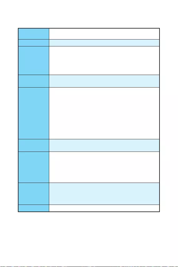
3
Технические характеристики
Процессор Поддержка процессоров Intel® Core™ i3/i5/i7, Intel® Pentium® и
Celeron® 6-го поколения для сокета LGA1151
Чипсет Intel® H110
Память
y2x DDR4 слота памяти с поддержкой до 32 ГБ
Поддержка DDR4 2133 МГц
yДвухканальная архитектура памяти
yПоддержка non-ECC, небуферизованной памяти
yПоддержка Intel® Extreme Memory Profile (XMP)
Слоты
расширения
y1x слот PCIe 3.0 x16
y2x слота PCIe 2.0 x1
Встроенная
графика
yH110M PRO-VH PLUS
1x порт VGA, с поддержкой максимального разрешения
2048×1536@50Гц , 2048×1280@60Гц , 1920×1200@60Гц
1x порт HDMI™, с поддержкой максимального разрешения
4096×2160@24Гц , 2560×1600@60Гц
yH110M PRO-VD PLUS
1x порт VGA, с поддержкой максимального разрешения
2048×1536@50Гц , 2048×1280@60Гц , 1920×1200@60Гц
1x порт DVI-D, с поддержкой максимального разрешения
1920×1200@60Гц
Подключение
накопителей
Чипсет Intel® H110
y4x порта SATA 6 Гб/с
USB
yЧипсет Intel® H110
4x порта USB 3.1 Gen1 (SuperSpeed USB) (2 порта на
задней панели, 2 порта доступны через внутренние USB
разъемы)
6x портов USB 2.0 (High-speed USB) (2 порта на задней
панели, 4 порта доступны через внутренние USB разъемы)
Аудио
yRealtek® ALC887 Codec
y7.1-канальный High Definition Audio*
* Модуль HD аудио передней панели корпуса является
необходимым для вывода многоканального звука 7.1.
LAN 1x Гигабитный сетевой контроллер Realtek® RTL8111H
Продолжение на следующей странице

4
Продолжение с предыдущей страницы
Разъемы
задней панели
y1x порт PS/2 мышь
y1x порт PS/2 клавиатура
y2x порта USB 3.1 Gen1
y1x порт HDMI™ (H110M PRO-VH PLUS)
y1x порт DVI-D (H110M PRO-VD PLUS)
y1x порт VGA
y1x порт LAN (RJ45)
y2x порта USB 2.0
y3x аудиоразъема
Разъемы на
плате
y1x 24-контактный разъем питания ATX
y1x 4-контактный разъем питания ATX 12В
y4x разъема SATA 6 Гб/с
y2x разъема USB 2.0 (Поддержка 4-х дополнительных портов
USB 2.0)
y1x разъем USB 3.1 Gen1 (Поддержка 2-х дополнительных
портов USB 3.1 Gen1)
y1x 4-контактных разъем вентилятора процессора
y1x 4-контактных разъем вентилятора системы
y1x аудиоразъем передней панели
y2x разъема передней панели
y1x разъем модуля TPM
y1x разъем последовательного порта
y1x разъем датчика открытия корпуса
y1x джампер очистки данных CMOS
Контроллер
ввода-вывода NUVOTON NCT5563D
Аппаратный
мониторинг
yОпределение температуры процессора/системы
yОпределение скорости вентиляторов процессора/системы
yУправление скоростью вентиляторов процессора/системы
Форм-фактор yMicro-ATX Форм-фактор
y8.9 x 6.8 дюйма (22.6 x 17.3 см)
Параметры
BIOS
y1x 64 Мб флэш
yUEFI AMI BIOS
yACPI 5.0, PnP 1.0a, SM BIOS 2.8
yМультиязычный интерфейс
Продолжение на следующей странице

5
Продолжение с предыдущей страницы
Программное
обеспечение
yДрайверы
yCOMMAND CENTER
yLIVE UPDATE 6
yFAST BOOT
ySUPER CHARGER
yM-CLOUD
yRAMDISK
yIntel® Small Business Basics
yNETWORK GENIE
yIntel® Extreme Tuning Utility
yNorton™ Security
yGoogle Chrome™, Google Toolbar, Google Drive
yCPU-Z
yMYSTIC LIGHT
MSI
Эксклюзивные
функции
yCLICK BIOS
yCOMMAND CENTER
yRAMDISK
ySURPER CHARGER
yFAST BOOT
yLIVE UPDATE 6
yM-CLOUD
yMYSTIC LIGHT
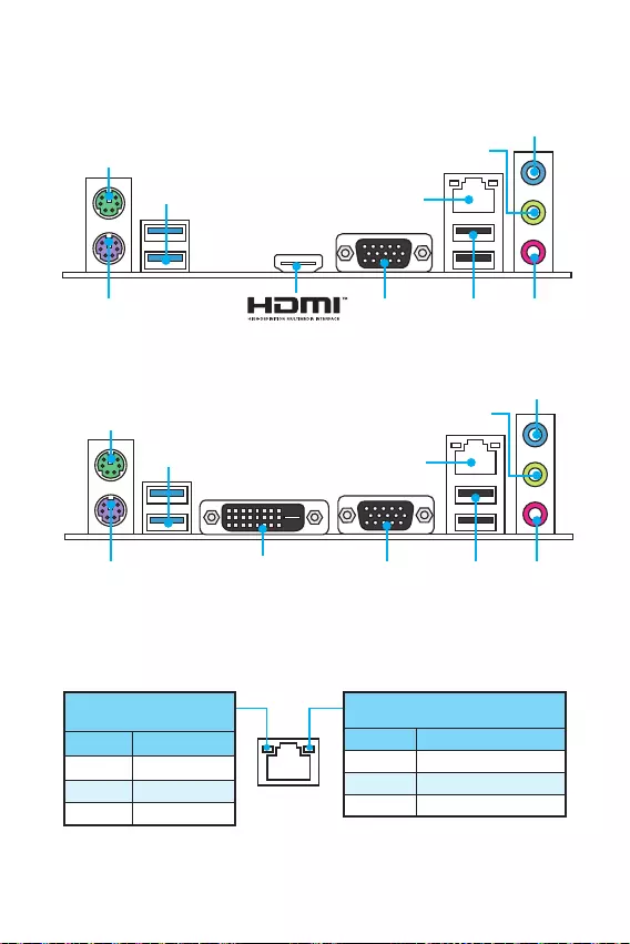
6 /
Задняя панель ввода/ вывода
DVI-D
H110M PRO-VD PLUS
PS/2 мышь
LAN
USB 3.1 Gen1
USB 2.0
VGAPS/2
клавиатура
H110M PRO-VH PLUS
Линейный
вход
Линейный
выход
Микрофонный
вход
Подключение/ Работа
индикатора
Состояние Описание
Выкл. Не подключен
Желтый Подключен
Мигает Передача данных
Скорость передачи данных
Состояние Описание
Выкл 10 Мбит/с подключение
Зеленый 100 Мбит/с подключение
Оранжевый 1 Гбит/с подключение
Таблица состояния индикатора порта LAN
PS/2 мышь
LAN
USB 3.1 Gen1
VGAPS/2
клавиатура
Линейный
вход
Линейный
выход
USB 2.0 Микрофонный
вход
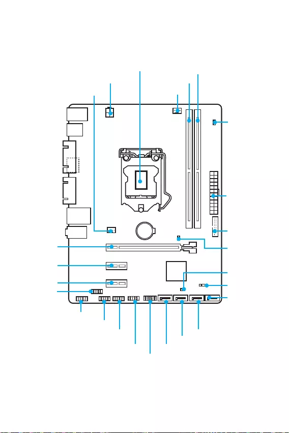
7
/
BAT1
DVI- D(optional)
HDMI(optional)
CPUFAN
JPWR2
PCI_E1
PCI_E2
PCI_E3
DIMM1
SYSFAN1
DIMM2
JUSB3
JFP1
JUSB1
SATA1
JFP2
JUSB2
JPWR1
EZ Debug LED
JCI1
SATA2
SATA3
SATA4
JTPM1
JBAT1
JCOM1
Процессорный
сокет
Компоненты материнской платы
JAUD1

8
Процессорный сокет
Пожалуйста, установите процессор в процессорный сокет, как показано ниже.
Внимание!
y
ВНИМАНИЕ! Перед установкой или заменой процессора, необходимо отключить
кабель питания.
y
Пожалуйста, сохраните защитную крышку процессорного сокета после
установки процессора. Любые возможные гарантийные случаи, связанные
с работой материнской платы, MSI будет рассматривать только, при наличии
защитной крышки на процессорном сокете.
y
При установке процессора обязательно установите процессорный кулер. Кулер,
представляющий собой систему охлаждения процессора, предупреждает
перегрев и обеспечивает стабильную работу системы.
y
Перед включением системы проверьте герметичность соединения между
процессором и радиатором.
y
Перегрев может привести к серьезному повреждению процессора и
материнской платы. Всегда проверяйте работоспособность вентилятора для
защиты процессора от перегрева. При установке кулера нанесите ровный
слой термопасты (или термоленту) на крышку установленного процессора для
улучшения теплопередачи.
y
Если процессор не установлен, всегда защищайте контакты процессорного
сокета пластиковой крышкой.
y
Если вы приобрели отдельно процессор и процессорный кулер, подробное
описание установки см. в документации в данному кулеру.
1
4
6
5
78
9
3
2
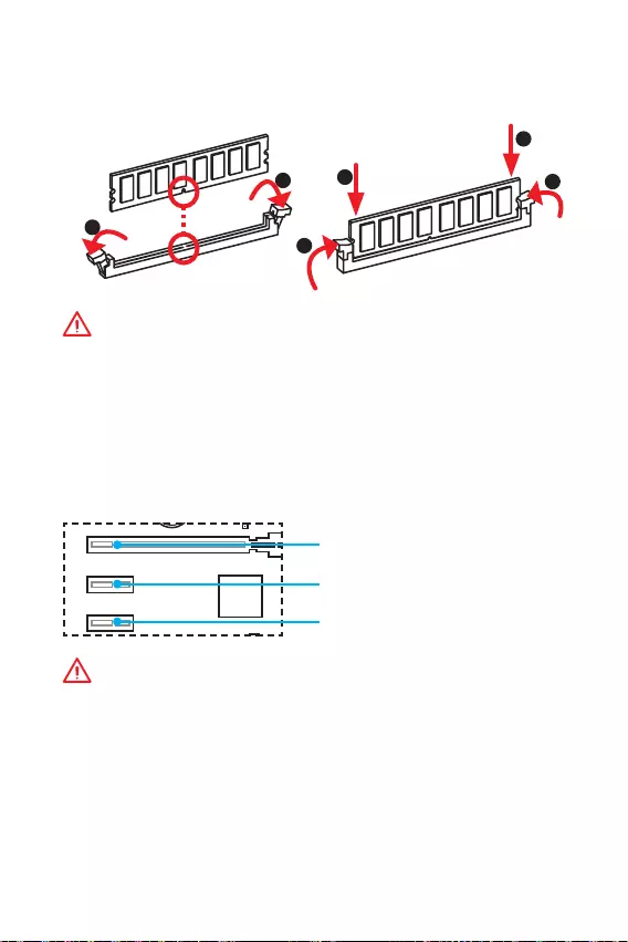
9
Слоты DIMM
Пожалуйста, установите модуль памяти в слот DIMM, как показано ниже.
Внимание!
y
В связи со спецификой использования ресурсов чипсета, доступный объем
памяти будет немного меньше, чем объем установленный.
y
Пожалуйста, обратите внимание на то, что максимальная емкость адресуемой
памяти для 32-бит ОС Windows, составляет не более 4 ГБ. Если вы хотите
использовать более 4ГБ оперативной памяти на материнской плате,
рекомендуется устанавливать 64-бит ОС Windows.
PCI_E1~3: Слот расширения PCIe
BAT1
DVI- D(optional)
HDMI(optional)
PCI_E1: PCIe 3.0 x16 слот
PCI_E2: PCIe 2.0×1 слот
PCI_E3: PCIe 2.0×1 слот
Внимание!
Перед установкой или извлечением плат расширения убедитесь, что кабель
питания отключен от электрической сети. Прочтите документацию на карту
расширения и выполните необходимые дополнительные аппаратные или
программные изменения для данной карты.
1
12
3
3
2
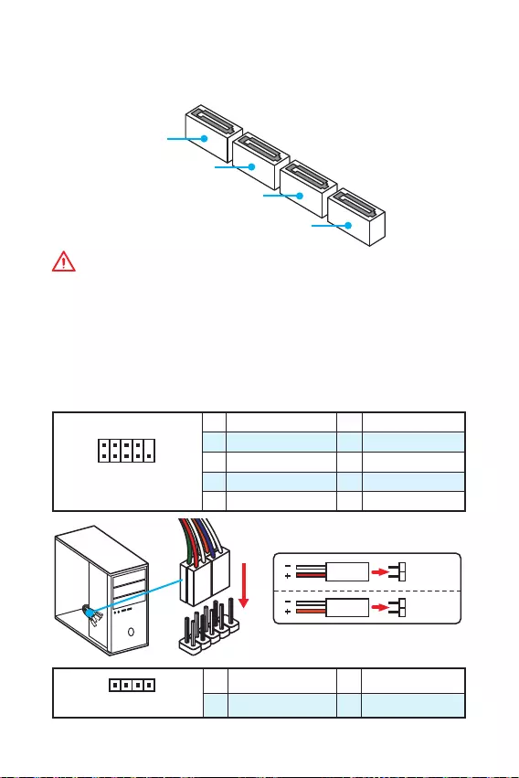
10
SATA1~4: Разъемы SATA 6 Гб/с
Эти разъемы представляют собой интерфейсные порты SATA 6 Гб/с. К каждому
порту можно подключить одно устройство SATA.
SATA3
SATA2
SATA4
SATA1
Внимание!
y
Избегайте перегибов кабеля SATA под прямым углом. В противном случае,
возможна потеря данных при передаче.
y
Кабель SATA оснащен одинаковыми коннекторами с обеих сторон. Однако,
для экономии занимаемого пространства к материнской плате рекомендуется
подключать плоский разъем.
JFP1, JFP2: Разъемы передней панели
Эти разъемы служат для подключения кнопок и светодиодных индикаторов,
расположенных на передней панели.
1
2 10
9
JFP1
1 HDD LED + 2 Power LED +
3 HDD LED — 4 Power LED —
5 Reset Switch 6 Power Switch
7 Reset Switch 8 Power Switch
9 Reserved 10 No Pin
1
JFP2
1 Speaker — 2 Buzzer +
3 Buzzer — 4 Speaker +
HDD LED
RESET SW
HDD LED HDD LED —
HDD LED +
POWER LED —
POWER LED +
POWER LED
JFP1
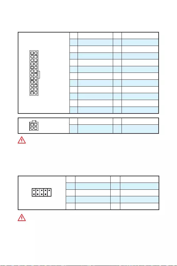
11
JPWR1~2: Разъемы питания
Данные разъемы предназначены для подключения коннекторов питания ATX.
24
131
12
JPWR1
1 +3.3V 13 +3.3V
2 +3.3V 14 -12V
3 Ground 15 Ground
4 +5V 16 PS-ON#
5 Ground 17 Ground
6 +5V 18 Ground
7 Ground 19 Ground
8 PWR OK 20 Res
9 5VSB 21 +5V
10 +12V 22 +5V
11 +12V 23 +5V
12 +3.3V 24 Ground
3
2 1
4JPWR2
1 Ground 3 +12V
2 Ground 4 +12V
Внимание!
Для обеспечения стабильной работы системной платы проверьте надежность
подключения всех кабелей питания к блоку питания АТХ.
JUSB1~2: Разъемы USB 2.0
Данные разъемы предназначены для подключения портов USB 2.0 на передней
панели.
1
2 10
9
1VCC 2VCC
3 USB0- 4 USB1-
5 USB0+ 6 USB1+
7 Ground 8 Ground
9 No Pin 10 NC
Внимание!
y
Помните, что во избежание повреждений необходимо правильно подключать
контакты VCC и Ground.
y
Для того, чтобы зарядить ваш iPad, iPhone и iPod портами USB, пожалуйста,
установите утилиту MSI® SUPER CHARGER.
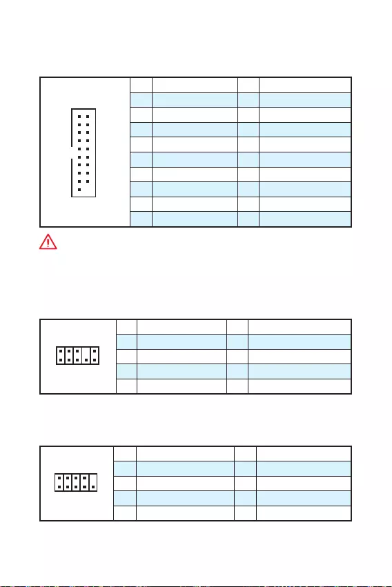
12
JUSB3: Разъем USB 3.1 Gen1
Данный разъем предназначен для подключения портов USB 3.1 Gen1 на передней
панели.
1
10 11
20
1Power 11 USB2.0+
2 USB3_RX_DN 12 USB2.0-
3 USB3_RX_DP 13 Ground
4 Ground 14 USB3_TX_C_DP
5 USB3_TX_C_DN 15 USB3_TX_C_DN
6 USB3_TX_C_DP 16 Ground
7 Ground 17 USB3_RX_DP
8 USB2.0- 18 USB3_RX_DN
9 USB2.0+ 19 Power
10 Ground 20 No Pin
Внимание!
Помните, что во избежание повреждений необходимо правильно подключать
контакты питания и земли.
JAUD1: Разъем аудио передней панели
Данный разъем предназначен для подключения аудиоразъемов передней
панели.
1
2 10
9
1 MIC L 2 Ground
3 MIC R 4 NC
5 Head Phone R 6 MIC Detection
7 SENSE_SEND 8 No Pin
9 Head Phone L 10 Head Phone Detection
JCOM1: Разъем последовательного порта
Этот разъем позволяет подключить последовательный порт, размещенный на
внешнем брекете.
1
2 10
9
1 DCD 2 SIN
3 SOUT 4 DTR
5 Ground 6 DSR
7 RTS 8 CTS
9 RI 10 No Pin
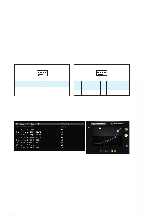
13
CPUFAN, SYSFAN1: Разъемы вентиляторов
Разъемы вентиляторов можно разделить на два типа: с PWM (PulseWidth
Modulation) управлением и управлением постоянным током. Разъемы
вентиляторов с PWM управлением имею контакт с постоянным напряжением
12В, а также контакт с сигналом управления скоростью вращения. Управление
скоростью вращения вентиляторов с управлением постоянным током,
осуществляется через соответсвующие разъемы путем изменения величины
напряжения. Поэтому, при подключении 3-х контактного (Non-PWM) вентилятора
к разъему для вентилятора PWM, скорость вентилятора всегда будет
максимальной. Работа такого вентилятора может оказаться достаточно шумной.
1
CPUFAN
1 Ground 2 +12V
3 Sense 4 Speed Control
Signal
1
SYSFAN1
1 Ground 2 Voltage
Control
3 Sense 4 NC
Разъем вентилятора с PWM управлением Разъем вентилятора режима напряжения
Управление скоростью вентилятора
Существуют два способа управления скоростью вращения вентилятора.
С помощью настроек BIOS > Advanced > Hardware Monitor, и с помощью
приложения COMMAND CENTER.
COMMAND CENTER
Аппаратный мониторинг в BIOS подменю позволяет вам установить уровень
температуры и соответствующие уровни скорости вентилятора.
COMMAND CENTER позволяет путем изменения положения градиентных точек,
регулировать скорость вращения вентилятора в зависимости от температуры
процессора.
BIOS > Advanced > Hardware Monitor
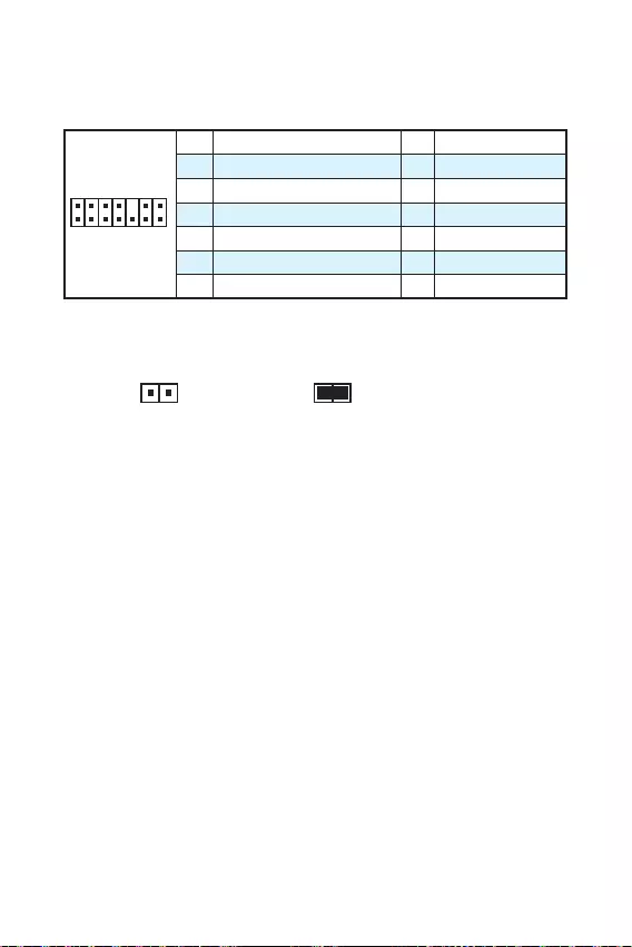
14
JTPM1: Разъем модуля ТРМ
Данный разъем испльзуется для подключения модуля ТРМ (Trusted Platform
Module). Дополнительные сведения см. в описании модуля ТРМ.
1
2 14
13
1 LPC Clock 2 3V Standby power
3 LPC Reset 4 3.3V Power
5 LPC address & data pin0 6 Serial IRQ
7 LPC address & data pin1 8 5V Power
9 LPC address & data pin2 10 No Pin
11 LPC address & data pin3 12 Ground
13 LPC Frame 14 Ground
JCI1: Разъем датчика открытия корпуса
К этому разъему подключается кабель от датчика открытия корпуса.
Нормально
(По умолчанию)
Разрешить запись по
событию открытия корпуса
Использование датчика открытия корпуса
1. Подключите подключите датчик открытия корпуса к разъему JCI1.
2. Закройте крышку корпуса.
3. Войдите в BIOS > Security > Chassis Intrusion Configuration.
4. Установите Chassis Intrusion на Enabled.
5. Нажмите клавишу F10, чтобы сохранить настройки и выйти, а затем нажмите
клавишу Enter, чтобы выбрать Yes.
6. При открытии корпуса на экране будет появлятся предупреждающее
сообщение каждый раз при включении компьютера.
Сброс сообщения об открытии корпуса
1. Войдите в BIOS > Security > Chassis Intrusion Configuration.
2. Выберите Chassis Intrusion, Reset.
3. Нажмите клавишу F10, чтобы сохранить изменения и выйти, а затем нажмите
клавишу Enter, чтобы выбрать Yes.
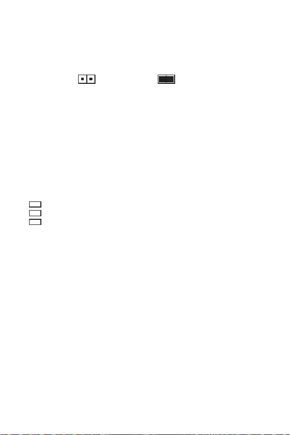
15
JBAT1: Джампер очистки данных CMOS (Сброс BIOS)
На плате установлена CMOS память с питанием от батарейки для хранения
данных о конфигурации системы. Для сброса конфигурации системы (очистки
данных CMOS памяти), воспользуйтесь этим джампером.
Сохранение данных
(По умолчанию)
Очистка данных/
Сброс BIOS
Сброс настроек BIOS до значений по умолчанию
1. Выключите компьютер и отключите шнур питания.
2. Используйте джампер, чтобы замкнуть соответствующие контакты JBAT1 в
течение 5-10 секунд.
3. Снимите джампер с контактов JBAT1.
4. Подключите шнур питания и включите компьютер.
EZ Debug LED: Индикатор отладки
Индикатор сигнализирует о неисправностях на материнской плате.
CPU — указывает, что процессор не обнаружен или поврежден.
DRAM — указывает, что память DRAM не обнаружена или повреждена.
VGA — указывает, что видеокарта не обнаружена или повреждена.
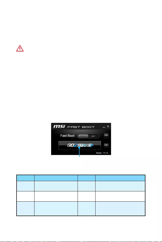
16 BIOS
Настройка BIOS
Настройки по умолчанию обеспечивают оптимальную производительность и
стабильность системы при нормальных условиях. Если вы недостаточно хорошо
знакомы с BIOS, . Это
позволит избежать возможных повреждений системы, а также проблем с
загрузкой.
Внимание!
y
С целью улучшения производительности, меню BIOS постоянно обновляется. В
связи с этим данное описание может немного отличаться от последней версии
BIOS и может использоваться в качестве справки. Для описания какого либо
пункута меню настроек BIOS, вы можете обратиться к информационной панели
.
y
Изображения в этой главе приведены исключительно в справочных целях и
могут отличаться от фактических.
Вход в настройки BIOS
Ниже представлены методы входа в настройки BIOS.
yНажмите клавишу Delete, когда появляется сообщение на экране Press DEL key
to enter Setup Menu, F11 to enter Boot Menu во время загрузки.
yПри помощи приложения MSI FAST BOOT. Нажмите на кнопку GO2BIOS и
выберите OK. Система перезагрузится и автоматически войдет в настройки
BIOS.
Нажмите на кнопку GO2BIOS
Функциональные клавиши
Клавиша Функция Клавиша Функция
F1 Общая справка F4 Вход в меню технических
параметров процессора
F5 Вход в меню Memory-Z F6 Загрузить оптимизированные
настройки по умолчанию
F10 Сохранение изменений и
перезагрузка* F12
Сделать скриншот и
сохранить его в флэш-диск
USB (только FAT/ FAT32)
* При нажатии клавиши F10 появится информационное окно. Выберите Yes или
No, чтобы подтвердить выбор.

17
BIOS BIOS
Сброс BIOS
В некоторых ситуациях необходиимо выполнить восстановление настройек BIOS
до значений по умолчанию. Существует несколько способов сброса настроек:
yВойдите в BIOS и нажмите клавишу F6 для загрузки оптимизированных
значений по умолчанию.
yЗамкните джампер Clear CMOS на материнской плате.
Внимание!
За более подробной информацией о сбросе настроек BIOS, обратитесь к разделу
джампера очистки данных CMOS.
Обновление BIOS
Обновление BIOS при помощи M-FLASH
Подготовительные операции:
Пожалуйста, скачайте последнюю версию файла BIOS с сайта MSI, который
соответствует вашей модели материнской платы. Сохраните файл BIOS в флэш-
диске USB.
Обновление BIOS:
1. Вставьте флэш-диск USB, содержащий файл обновления в компьютер.
2. Перезагрузите систему, и нажмите клавишу Del для входа в настройки BIOS во
время процедуры POST.
3. Войдите в BIOS > M-FLASH > Select one file to update BIOS and ME, выберите
файл BIOS для выполнения процесса обновления BIOS.
4. После завершения процесса обновления, система перезагрузится.
Обновление BIOS при помощи Live Update 6
Перед обновлением:
Убедитесь, что драйвер локальной сети уже установлен и подключение к
интернету установлено.
Обновление BIOS:
1. Установите и запустите MSI LIVE UPDATE 6.
2. Выберите Manual scan.
3. Поставьте галочку в поле MB BIOS и нажмите на кнопку Scan.
4. Выберите MB BIOS и нажмите на значок , чтобы загрузить и установить
последнюю версию файла BIOS.
5. Нажмите кнопку Next и выберите In Windows mode. И затем нажмите кнопку
Next и Start для запуска обновления BIOS.
6. По завершению процесса обновления, система перезагрузится
автоматически.

18
Описание программного обеспечения
Установка Windows® 7/ 8.1/ 10
1. Включите компьютер.
2. Вставьте диск Windows® 7/ 8.1/ 10 в привод для оптических дисков.
: Из-за ограничений, накладываемых установщиком Windows
®
7, USB оптические приводы и флеш накопители не поддерживаются.
3. Нажмите кнопку Restart на корпусе компьютера.
4. В Windows® 8.1/ 10, пропустите этот шаг. В Windows® 7, войдите в меню BIOS
Advanced > Windows OS Configuration > Windows 7 Installation и установить
пункт включен, сохраните изменения и перезагрузите.
: При установке Windows® 7 рекоммендуется подключать USB
клавиатуру/ USB мышь к портам USB, расположенным слева.
5. Нажмите клавишу F11 во время POST (Power-On Self Test) компьютера, чтобы
войти в меню загрузки.
6. Выберите оптический привод в меню загрузки.
7. Нажмите любую клавишу, когда на экране показывает сообщение Press any
key to boot from CD or DVD…
8. Следуйте инструкциям на экране, чтобы установить Windows® 7/ 8.1/ 10.
Установка драйверов
1. Загрузите компьютер в Windows® 7/ 8.1/ 10.
2. Вставьте диск с драйверами MSI® Driver Disc в привод для оптических дисков.
3. Автоматически отобразится окно установщика, который найдет и перечислит
все необходимые драйверы.
4. Нажмите кнопку Install.
5. Начнется установка драйверов. После ее завершения будет предложено
перезапустить систему.
6. Нажмите кнопку OK для завершения.
7. Перезапустите компьютер.
Установка утилит
Перед установкой утилиты необходимо выполнить установку драйверов.
1. Вставьте диск с драйверами MSI® Driver Disc в привод для оптических дисков.
2. Автоматически отобразится окно установщика.
3. Нажмите вкладку Utilities.
4. Выберите необходимые для установки утилиты.
5. Нажмите кнопку Install.
6. Начнется установка программного обеспечения. После ее завершения будет
предложено перезапустить систему.
7. Нажмите кнопку OK для завершения.
8. Перезапустите компьютер.
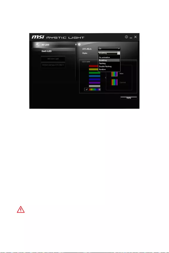
19
MYSTIC LIGHT
MYSTIC LIGHT позволяет контролировать светодиодные индикаторы на
материнской плате и видеокартах.
yAll LED — управляет всеми светодиодами на материнской плате и видеокартах.
yEach LED — отдельно управляет каждым сегментом светодиодов на материнской
плате и видеокартах.
yLED effects — включает или выключает светодиоды.
yStyles — позволяет выбрать режим работы светодиодов из выпадающего списка.
yLED color () — позволяет изменять цвет светодиода. Данный
параметр зависит от приобретаемой модели материнской платы.
yApply Button — применяет настройки режимов работы к светодиодам.
Управление опцией Audio line
yПо умолчанию настройка параметра Audio line в BIOS устанавливается в режим
Breathing.
yПосле установки приложения MYSTIC LIGHT и перезагрузки операционной
системы, режим параметра Audio line по умолчанию устанавливается в No
animation. При изменении режима Audio line в MYSTIC LIGHT и нажатии
кнопки Apply, программное обеспечение автоматически изменит настройки в
операционной системе и BIOS.
Примечание: При закрытии приложения MYSTIC LIGHT в операционной системе,
Audio line автоматически устанавливается режим No animation.
Внимание!
y
Рекомендуется настраивать режимы Audio line при помощи утилиты MYSTIC
LIGHT.
y
При работе в DOS, Audio line устанавливается в режим Breathing при выборе:
Flashing, Double Flashing и Random.

20 Note
Note

1
< 1>
……………………………………………………………………………………………..2
…………………………………………………………………………………………………… 3
I/O ………………………………………………………………………………………. 6
LAN LED ……………………………………………………………………………..6
……………………………………………………………………………………………..7
CPU ………………………………………………………………………………………………8
DIMM …………………………………………………………………………………………….9
PCI_E1~3: PCIe ………………………………………………………………………..9
SATA1~4: SATA 6Gb/s ……………………………………………………………………10
JFP1, JFP2: …………………………………………………………………….10
JPWR1~2: ……………………………………………………………………………..11
JUSB1~2: USB 2.0 …………………………………………………………………………11
JUSB3: USB 3.1 Gen1 ……………………………………………………………………12
JAUD1: ……………………………………………………………………………12
JCOM1: …………………………………………………………………………..12
CPUFAN, SYSFAN1: ………………………………………………………………..13
JTPM1: TPM …………………………………………………………………………..14
JCI1: ………………………………………………………………………..14
JBAT1: CMOS ( BIOS) ………………………………………………………15
EZ Debug LED: LED ……………………………………………………………15
BIOS ………………………………………………………………………………………….16
BIOS …………………………………………………………………………………….16
BIOS…………………………………………………………………………………………….17
BIOS…………………………………………………………………………………………….17
……………………………………………………………………………………………18
Windows® 7/ 8.1/ 10 ………………………………………………………………………18
……………………………………………………………………………………………..18
……………………………………………………………………………………………..18
RGB LED ………………………………………………………………………..19
MSI® H110M PRO-VD PLUS/ H110M PRO-
VH PLUS BIOS

2
y (ESD)
y
y
y (ESD) ESD
y
y
y
y
y
y
y
y
y
y
y
y 60 ( 140 )
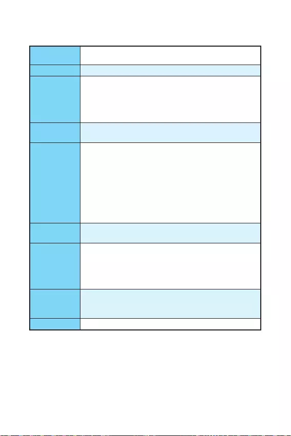
3
CPU LGA1151 Intel® Core™ i3/i5/i7 Intel®
Pentium® Celeron®
yIntel® H110
y2 DDR4 32GB
DDR4 2133 MHz
y
y -ECC —
y Intel® (XMP)
y1 PCIe 3.0 x16
y2 PCIe 2.0×1
yH110M PRO-VH PLUS
1 VGA 2048×1536@50Hz,
2048×1280@60Hz, 1920×1200@60Hz
1 HDMI™ 4096×2160@24Hz,
2560×1600@60Hz
yH110M PRO-VD PLUS
1 VGA 2048×1536@50Hz,
2048×1280@60Hz, 1920×1200@60Hz
1 DVI-D 1920×1200@60Hz
Intel® H110
y4 SATA 6Gb/s
USB
yIntel® H110
4 USB 3.1 Gen1 (SuperSpeed USB) (2
USB 2 )
6 USB 2.0 (High-speed USB) (2
USB 4 )
yRealtek® ALC887
y7.1-*
* 7.1-
LAN 1 Realtek® RTL8111H

4
y1 PS/2
y1 PS/2
y2 USB 3.1 Gen1
y1 HDMI™ (H110M PRO-VH PLUS)
y1 DVI-D (H110M PRO-VD PLUS)
y1 VGA
y1 LAN (RJ45)
y2 USB 2.0
y3
y1 24-pin ATX
y1 4-pin ATX 12V
y4 SATA 6Gb/s
y2 USB 2.0 ( 4 USB 2.0 )
y1 USB 3.1 Gen1 ( 2 USB 3.1 Gen1 )
y1 4-pin CPU
y1 4-pin
y1
y2
y1 TPM
y1
y1
y1 CMOS
I/O NUVOTON NCT5563D
yCPU/
yCPU/
yCPU/
yMicro-ATX
y8.9 x 6.8 (22.6 x 17.3 )
BIOS
y1 64 Mb flash
yUEFI AMI BIOS
yACPI 5.0, PnP 1.0a, SM BIOS 2.8
y

5
y
yCOMMAND CENTER
yLIVE UPDATE 6
y
ySUPER CHARGER
y
y
yIntel®
y
y®
yNorton™
yGoogle ™Google Google
yCPU-Z
yRGB LED
MSI
yBIOS
yCOMMAND CENTER
y
ySURPER CHARGER
y
yLIVE UPDATE 6
y
yRGB LED
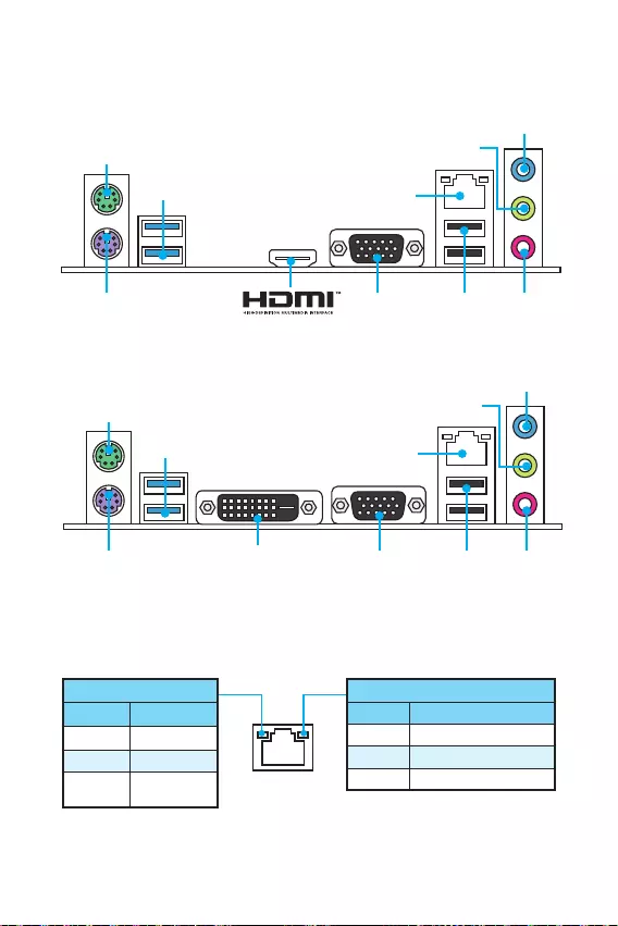
6 I/O
I/O
DVI-D
H110M PRO-VD PLUS
PS/2
LAN
USB 3.1 Gen1
USB 2.0
VGAPS/2
H110M PRO-VH PLUS
/
10 Mbps
100 Mbps
1 Gbps
LAN LED
PS/2
LAN
USB 3.1 Gen1
VGAPS/2
USB 2.0
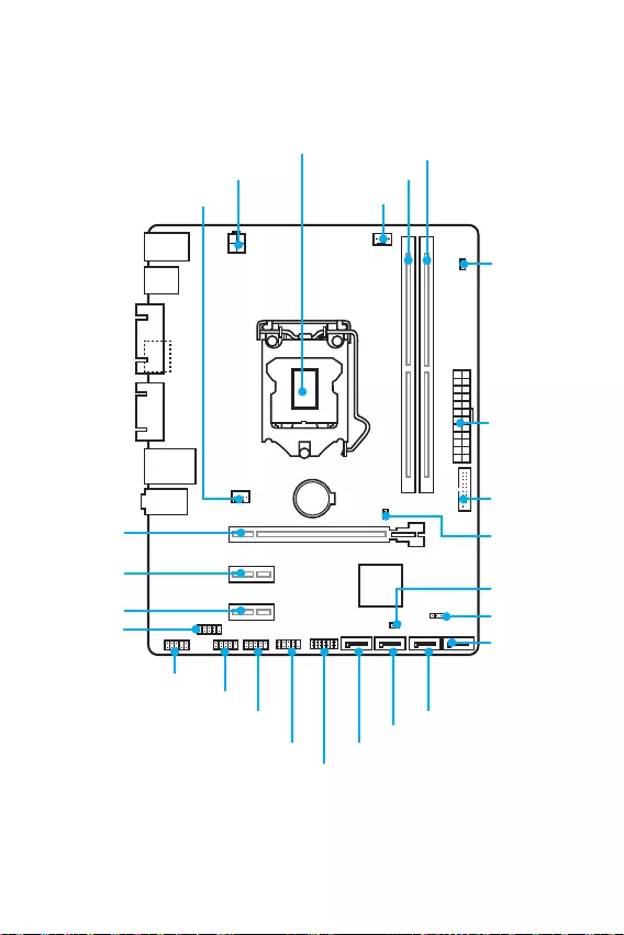
7
I/O
BAT1
DVI- D(optional)
HDMI(optional)
CPUFAN
JPWR2
PCI_E1
PCI_E2
PCI_E3
DIMM1
SYSFAN1
DIMM2
JUSB3
JFP1
JUSB1
SATA1
JFP2
JUSB2
JPWR1
EZ Debug LED
JCI1
SATA2
SATA3
SATA4
JTPM1
JBAT1
JCOM1
CPU
JAUD1
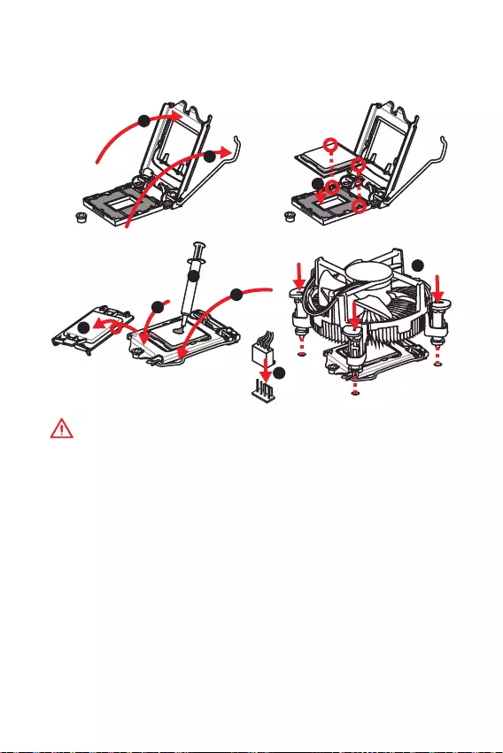
8
CPU
CPU CPU
y
CPU
y
CPU (RMA)
CPU
y
CPU CPU CPU
y
CPU CPU
y
CPU
CPU CPU (
)
y
CPU CPU
y
CPU / /
1
4
6
5
78
9
3
2
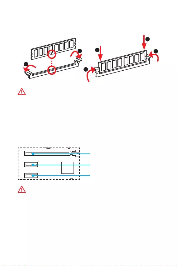
9
DIMM
DIMM
y
y
32 Windows 4GB
4GB 64
Windows
PCI_E1~3: PCIe
BAT1
DVI- D(optional)
HDMI(optional)
PCI_E1: PCIe 3.0 x16
PCI_E2: PCIe 2.0×1
PCI_E3: PCIe 2.0×1
1
12
3
3
2
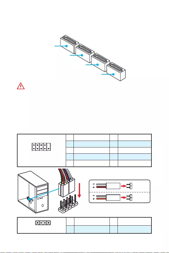
10
SATA1~4: SATA 6Gb/s
SATA 6Gb/s SATA
SATA3
SATA2
SATA4
SATA1
y
SATA 90
y
SATA
JFP1, JFP2:
LED
1
2 10
9
JFP1
1 HDD LED + 2 Power LED +
3 HDD LED — 4 Power LED —
5 Reset Switch 6 Power Switch
7 Reset Switch 8 Power Switch
9 Reserved 10 No Pin
1
JFP2
1 Speaker — 2 Buzzer +
3 Buzzer — 4 Speaker +
HDD LED
RESET SW
HDD LED HDD LED —
HDD LED +
POWER LED —
POWER LED +
POWER LED
JFP1
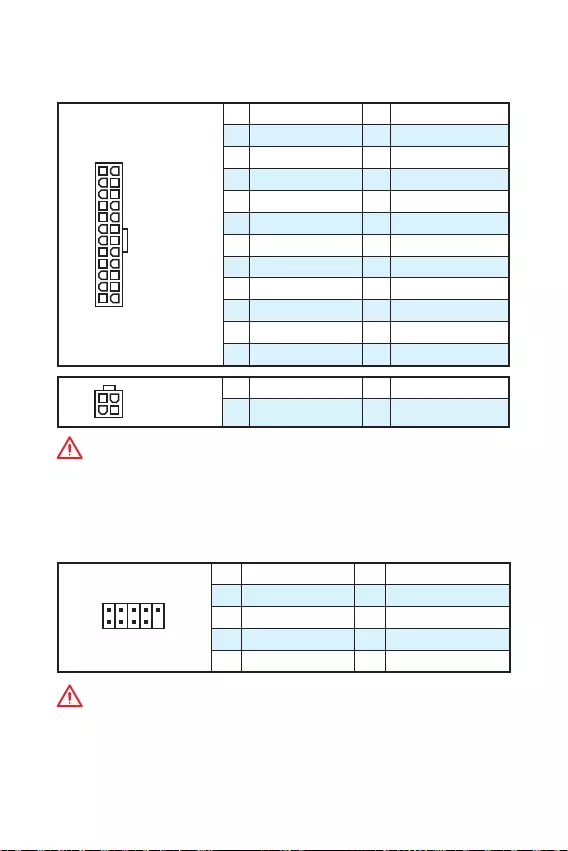
11
JPWR1~2:
ATX
24
131
12
JPWR1
1 +3.3V 13 +3.3V
2 +3.3V 14 -12V
3 Ground 15 Ground
4 +5V 16 PS-ON#
5 Ground 17 Ground
6 +5V 18 Ground
7 Ground 19 Ground
8 PWR OK 20 Res
9 5VSB 21 +5V
10 +12V 22 +5V
11 +12V 23 +5V
12 +3.3V 24 Ground
3
2 1
4JPWR2
1 Ground 3 +12V
2 Ground 4 +12V
ATX
JUSB1~2: USB 2.0
USB 2.0
1
2 10
9
1VCC 2VCC
3 USB0- 4 USB1-
5 USB0+ 6 USB1+
7 Ground 8 Ground
9 No Pin 10 NC
y
VCC
y
iPadiPhone iPod USB MSI® SUPER
CHARGER
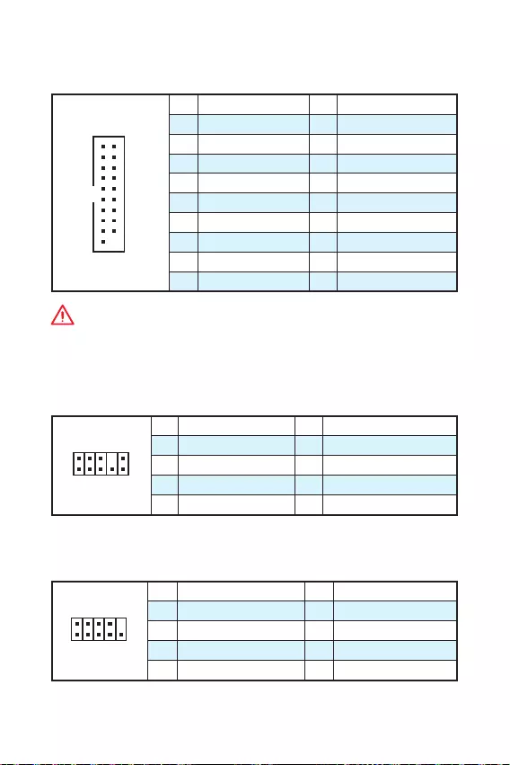
12
JUSB3: USB 3.1 Gen1
USB 3.1 Gen1
1
10 11
20
1Power 11 USB2.0+
2 USB3_RX_DN 12 USB2.0-
3 USB3_RX_DP 13 Ground
4 Ground 14 USB3_TX_C_DP
5 USB3_TX_C_DN 15 USB3_TX_C_DN
6 USB3_TX_C_DP 16 Ground
7 Ground 17 USB3_RX_DP
8 USB2.0- 18 USB3_RX_DN
9 USB2.0+ 19 Power
10 Ground 20 No Pin
JAUD1:
1
2 10
9
1 MIC L 2 Ground
3 MIC R 4 NC
5 Head Phone R 6 MIC Detection
7 SENSE_SEND 8 No Pin
9 Head Phone L 10 Head Phone Detection
JCOM1:
1
2 10
9
1 DCD 2 SIN
3 SOUT 4 DTR
5 Ground 6 DSR
7 RTS 8 CTS
9 RI 10 No Pin
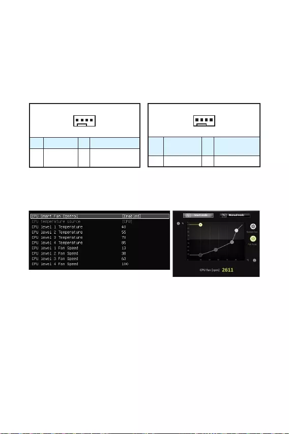
13
CPUFAN, SYSFAN1:
PWM () PWM
12V
3 (-PWM) PWM
100%
1
CPUFAN
1 Ground 2 +12V
3 Sense 4 Speed Control
Signal
1
SYSFAN1
1 Ground 2 Voltage
Control
3 Sense 4 NC
PWM
BIOS > Advanced > Hardware Monitor
COMMAND CENTER
COMMAND CENTER
BIOS
COMMAND CENTER CPU
BIOS > Advanced > Hardware Monitor
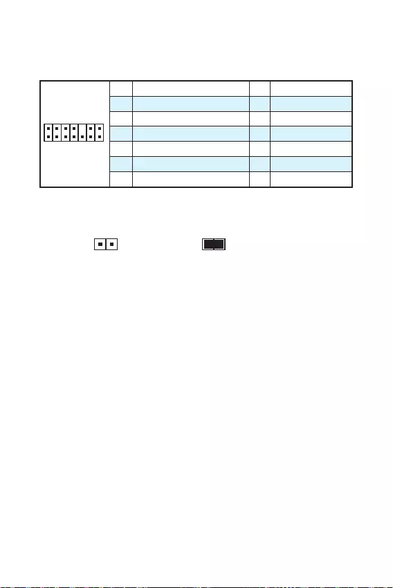
14
JTPM1: TPM
TPM () TPM
1
2 14
13
1 LPC Clock 2 3V Standby power
3 LPC Reset 4 3.3V Power
5 LPC address & data pin0 6 Serial IRQ
7 LPC address & data pin1 8 5V Power
9 LPC address & data pin2 10 No Pin
11 LPC address & data pin3 12 Ground
13 LPC Frame 14 Ground
JCI1:
()
1. JCI1 /
2.
3. BIOS > Security > Chassis Intrusion Configuration
4. Chassis Intrusion Enabled
5. F10 Enter Yes
6.
1. BIOS > Security > Chassis Intrusion Configuration
2. Chassis Intrusion Reset
3. F10 Enter Yes
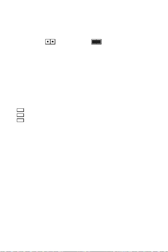
15
JBAT1: CMOS ( BIOS)
CMOS
CMOS
()
CMOS/
BIOS
BIOS
1.
2. JBAT1 5-10
3. JBAT1
4.
EZ Debug LED: LED
LED
CPU — CPU
DRAM — DRAM
VGA — GPU
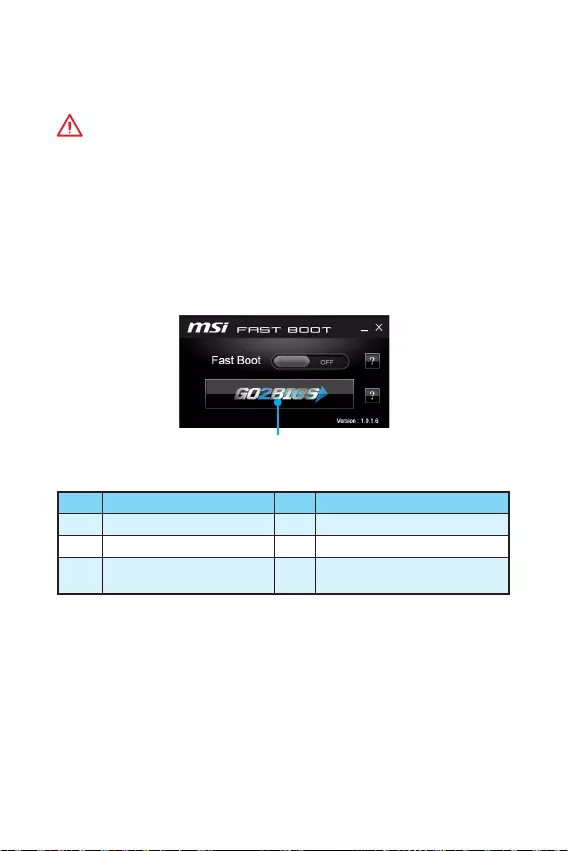
16 BIOS
BIOS
BIOS
y
BIOS
BIOS
y
BIOS
BIOS
y Press DEL key to enter Setup Menu, F11 to enter
Boot Menu Delete
y MSI FAST BOOT GO2BIOS OK
BIOS
GO2BIOS
F1 F4 CPU
F5 Memory-Z F6
F10 * F12 USB
(FAT/ FAT32 )
* F10 Yes
No

17
BIOS BIOS
BIOS
BIOS BIOS
y BIOS F6
y CMOS
CMOS BIOS
BIOS
M—FLASH BIOS
MSI BIOS BIOS USB
BIOS
1. USB
2. POST Del BIOS
3. BIOS > M-FLASH > Select one file to update BIOS and ME BIOS
BIOS
4. 100%
Live Update 6 BIOS
LAN
BIOS
1. MSI LIVE UPDATE 6
2. Manual scan
3. MB BIOS Scan
4. MB BIOS BIOS
5. Next Windows mode Next Start BIOS
6. 100%

18
Windows® 7/ 8.1/ 10
1.
2. Windows® 7/ 8.1/ 10
Windows® 7 USB U
3. Restart
4. windows® 8.1/ 10 Windows® 7 BIOS Advanced
> Windows OS Configuration > Windows 7 Installation
Windows® 7 USB /USB
USB
5. POST() F11
6.
7. Press any key to boot from CD or DVD…
8. Windows® 7/ 8.1/ 10
1. Windows® 7/ 8.1/ 10
2. MSI®
3.
4. Install
5.
6. OK
7.
1. MSI®
2.
3. Utilities
4.
5. Install
6.
7. OK
8.
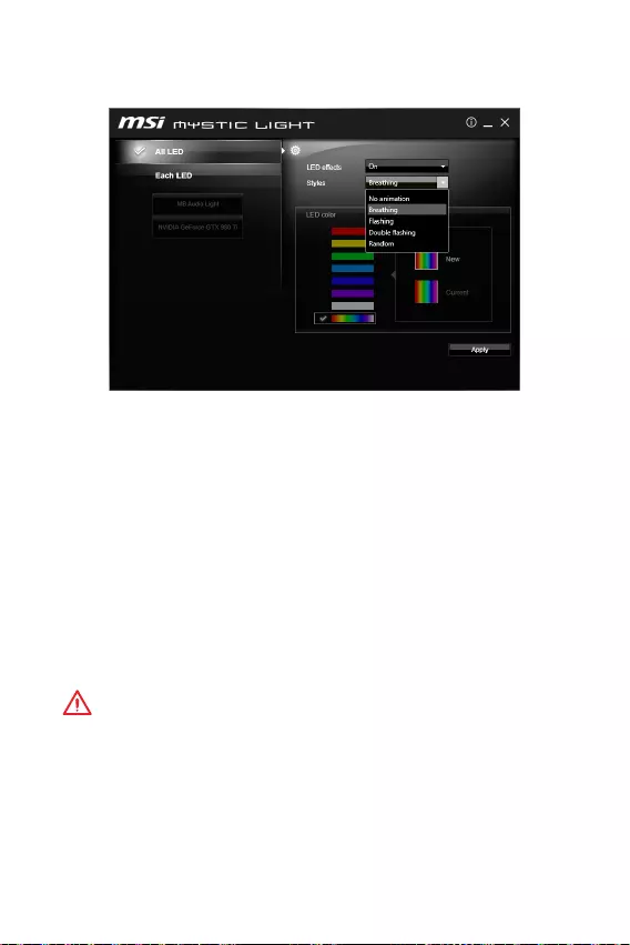
19
RGB LED
RGB LED (MYSTIC LIGHT) LED
yLED, All LED — LED
yLED, Each LED — LED
yLED (LED effects) — LED
y (Styles) — LED
yLED (, LED color) — LED
y (Apply) — LED
y BIOS
y RGB LED
RGB LED Apply
BIOS
RGB LED
y
RGB LED
y
DOS

20 Note
Note

1
< 1>
……………………………………………………………………………………………..2
………………………………………………………………………………………….3
…………………………………………………………………………………………………… 6
LED ……………………………………………………………………….6
……………………………………………………………………………………………..7
CPU ………………………………………………………………………………………………8
……………………………………………………………………………………………9
PCI_E1~3: PCIe ………………………………………………………………………..9
SATA1~4SATA 6Gb/s ……………………………………………………………………10
JFP1, JFP2 ………………………………………………………………………..10
JPWR1~2 ………………………………………………………………………………11
JUSB1~2USB 2.0 …………………………………………………………………………11
JUSB3USB 3.1 Gen1 …………………………………………………………………….12
JAUD1 ……………………………………………………………………………12
JCOM1 ………………………………………………………………………………12
CPUFAN, SYSFAN1 ……………………………………………………………13
JTPM1TPM …………………………………………………………………………..14
JCI1 ……………………………………………………………………………….14
JBAT1 CMOS ( BIOS) ……………………………………………………….15
EZ LED LED ……………………………………………………………….15
BIOS ………………………………………………………………………………………….16
BIOS …………………………………………………………………………………….16
BIOS…………………………………………………………………………………………….17
BIOS…………………………………………………………………………………………….17
……………………………………………………………………………………………18
Windows® 7/ 8.1/ 10 ………………………………………………………………………18
……………………………………………………………………………………….18
……………………………………………………………………………………….18
MYSTIC LIGHT ……………………………………………………………………………………..19
MSI® H110M PRO-VD PLUS/ H110M PRO-
VH PLUS BIOS

2
y (ESD)
y
y
y
y
y
y
y
y
y
y
y
y
y
y
y 60C (140F)
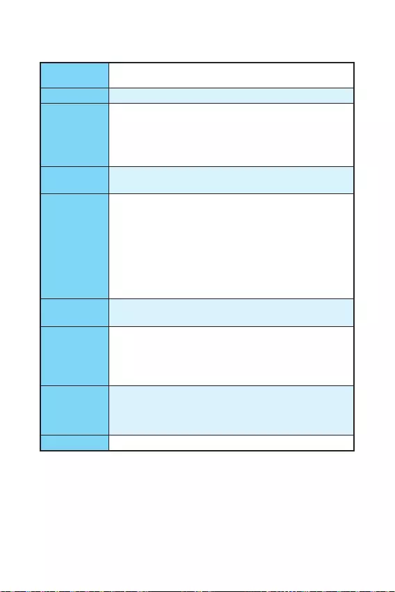
3
6 Intel® Core™ i3/i5/i7 LGA1151
Intel® Pentium® Celeron®
Intel® H110
y2 DDR4 32GB
DDR4 2133 MHz
y
y non-ECC
y Intel® Extreme Memory Profile (XMP)
y1 PCIe 3.0 x16
y2 PCIe 2.0 x1
yH110M PRO-VH PLUS
1 VGA 2048×1536@50Hz,
2048×1280@60Hz, 1920×1200@60Hz
1 HDMI™ 4096×2160@24Hz,
2560×1600@60Hz
yH110M PRO-VD PLUS
1 VGA 2048×1536@50Hz,
2048×1280@60Hz, 1920×1200@60Hz
1 DVI-D 1920×1200@60Hz
Intel® H110
y4 SATA 6Gb/s
USB
yIntel® H110
4 USB 3.1 Gen1 (SuperSpeed USB) (2
2 USB )
6 USB 2.0 (High-speed USB) (2 4
USB )
yRealtek® ALC887
y7.1 *
* 7.1
LAN 1 Realtek® RTL8111H Gigabit LAN

4
y1 PS/2
y1 PS/2
y2 USB 3.1 Gen1
y1 HDMI™ (H110M PRO-VH PLUS)
y1 DVI-D (H110M PRO-VD PLUS)
y1 VGA
y1 LAN (RJ45)
y2 USB 2.0
y3
y1 24-pin ATX
y1 4-pin ATX 12V
y4 SATA 6Gb/s
y2 USB 2.0 ( 4 USB 2.0 )
y1 USB 3.1 Gen1 ( 2 USB 3.1 Gen1 )
y1 4-pin CPU
y1 4-pin
y1
y2
y1 TPM
y1
y1
y1 CMOS
I/O NUVOTON NCT5563D
y/
y/
y/
yMicro-ATX
y8.9 x 6.8 (22.6 x 17.3 )
BIOS
y1x 64 Mb
yUEFI AMI BIOS
yACPI 5.0, PnP 1.0a, SM BIOS 2.8
y

5
y
yCOMMAND CENTER
yLIVE UPDATE 6
yFAST BOOT
ySUPER CHARGER
yM-CLOUD
yRAMDISK
yIntel® Small Business Basics
yNETWORK GENIE
yIntel® Extreme Tuning Utility
yNorton™ Security
yGoogle Chrome™,Google Toolbar, Google
yCPU-Z
yMYSTIC LIGHT
MSI
yCLICK BIOS
yCOMMAND CENTER
yRAMDISK
ySURPER CHARGER
yFAST BOOT
yLIVE UPDATE 6
yM-CLOUD
yMYSTIC LIGHT
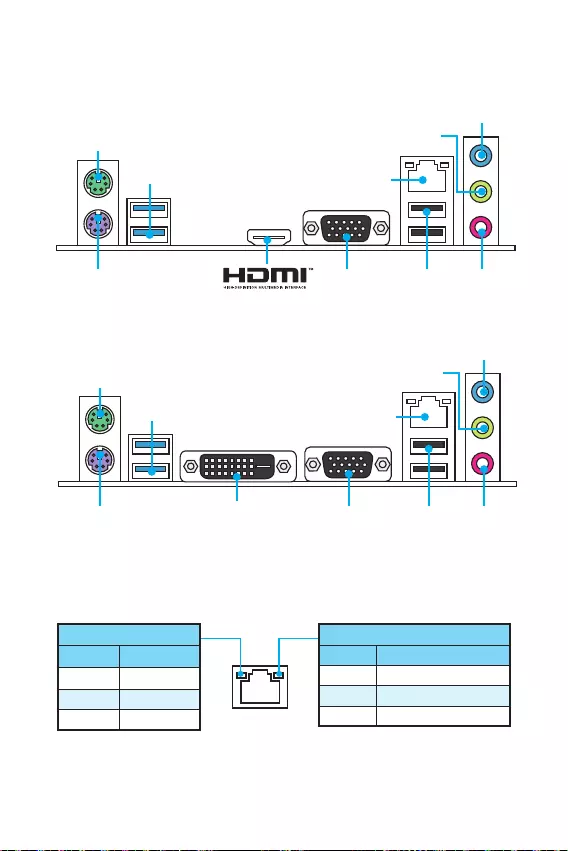
6
DVI-D
H110M PRO-VD PLUS
PS/2
USB 3.1 Gen1
USB 2.0
VGAPS/2
H110M PRO-VH PLUS
/
10 Mbps
100 Mbps
1 Gbps
LED
PS/2
USB 3.1 Gen1
VGAPS/2
USB 2.0
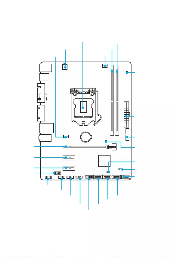
7
BAT1
DVI- D(optional)
HDMI(optional)
CPUFAN
JPWR2
PCI_E1
PCI_E2
PCI_E3
DIMM1
SYSFAN1
DIMM2
JUSB3
JFP1
JUSB1
SATA1
JFP2
JUSB2
JPWR1
EZ LED
JCI1
SATA2
SATA3
SATA4
JTPM1
JBAT1
JCOM1
CPU
JAUD1
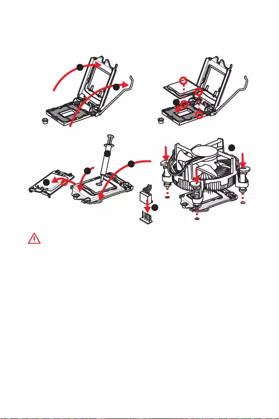
8
CPU
CPU CPU
y
y
CPU CPU
Return Merchandise Authorization (RMA)
y
CPUCPU
y
CPU
y
CPU CPU CPU
y
CPU CPU
y
/ /
1
4
6
5
78
9
3
2
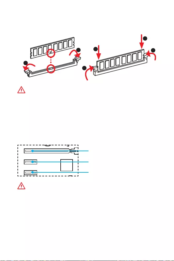
9
DIMM
y
y
32 Windows
4GB 4GB
64 Windows
PCI_E1~3: PCIe
BAT1
DVI- D(optional)
HDMI(optional)
PCI_E1: PCIe 3.0 x16
PCI_E2: PCIe 2.0×1
PCI_E3: PCIe 2.0×1
1
12
3
3
2
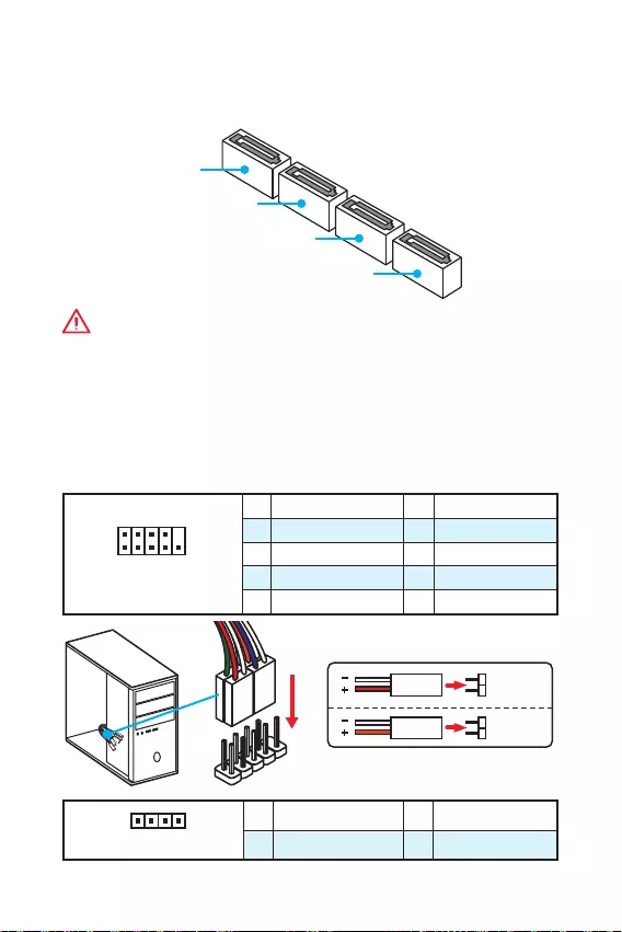
10
SATA1~4SATA 6Gb/s
SATA 6Gb/s SATA
SATA3
SATA2
SATA4
SATA1
y
SATA 90
y
SATA
JFP1, JFP2
LED
1
2 10
9
JFP1
1 HDD LED + 2 Power LED +
3 HDD LED — 4 Power LED —
5 Reset Switch 6 Power Switch
7 Reset Switch 8 Power Switch
9 Reserved 10 No Pin
1
JFP2
1 Speaker — 2 Buzzer +
3 Buzzer — 4 Speaker +
HDD LED
RESET SW
HDD LED HDD LED —
HDD LED +
POWER LED —
POWER LED +
POWER LED
JFP1
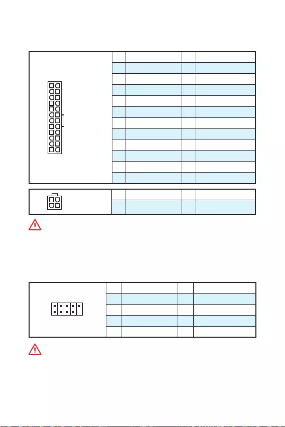
11
JPWR1~2
ATX
24
131
12
JPWR1
1 +3.3V 13 +3.3V
2 +3.3V 14 -12V
3 Ground 15 Ground
4 +5V 16 PS-ON#
5 Ground 17 Ground
6 +5V 18 Ground
7 Ground 19 Ground
8 PWR OK 20 Res
9 5VSB 21 +5V
10 +12V 22 +5V
11 +12V 23 +5V
12 +3.3V 24 Ground
3
2 1
4JPWR2
1 Ground 3 +12V
2 Ground 4 +12V
ATX
JUSB1~2USB 2.0
USB 2.0
1
2 10
9
1VCC 2VCC
3 USB0- 4 USB1-
5 USB0+ 6 USB1+
7 Ground 8 Ground
9 No Pin 10 NC
y
VCC
y
USB iPadiPhone iPod MSI®
SUPER CHARGER
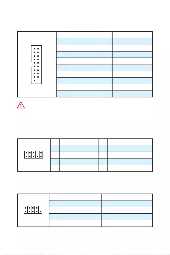
12
JUSB3USB 3.1 Gen1
USB 3.1 Gen1
1
10 11
20
1Power 11 USB2.0+
2 USB3_RX_DN 12 USB2.0-
3 USB3_RX_DP 13 Ground
4 Ground 14 USB3_TX_C_DP
5 USB3_TX_C_DN 15 USB3_TX_C_DN
6 USB3_TX_C_DP 16 Ground
7 Ground 17 USB3_RX_DP
8 USB2.0- 18 USB3_RX_DN
9 USB2.0+ 19 Power
10 Ground 20 No Pin
JAUD1
1
2 10
9
1 MIC L 2 Ground
3 MIC R 4 NC
5 Head Phone R 6 MIC Detection
7 SENSE_SEND 8 No Pin
9 Head Phone L 10 Head Phone Detection
JCOM1
1
2 10
9
1 DCD 2 SIN
3 SOUT 4 DTR
5 Ground 6 DSR
7 RTS 8 CTS
9 RI 10 No Pin
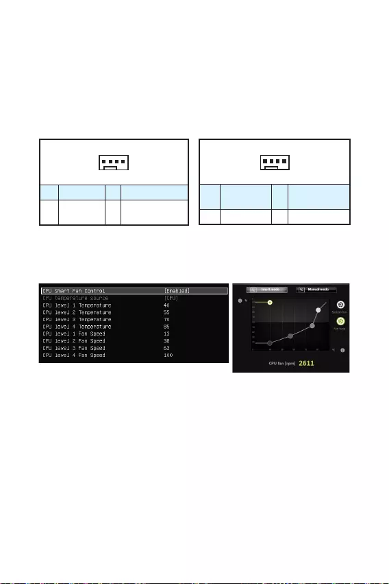
13
CPUFAN, SYSFAN1
(PWM) PWM
12V
3 ( PWM) PWM
1
CPUFAN
1 Ground 2 +12V
3 Sense 4 Speed Control
Signal
1
SYSFAN1
1 Ground 2 Voltage
Control
3 Sense 4 NC
PWM
BIOS > Advanced > Hardware
Monitor COMMAND CENTER
COMMAND CENTER
BIOS Hardware Monitor
COMMAND CENTER CPU
BIOS > Advanced > Hardware Monitor
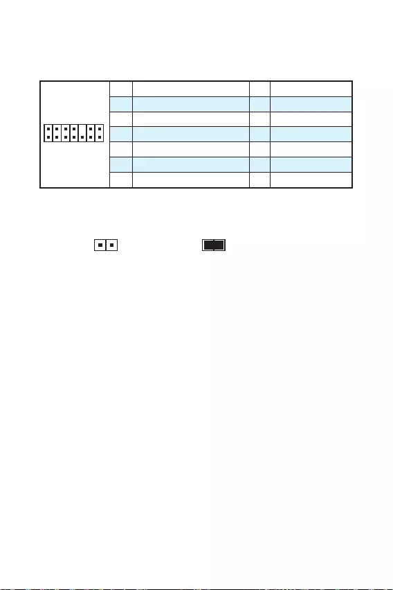
14
JTPM1TPM
(TPM) TPM
1
2 14
13
1 LPC Clock 2 3V Standby power
3 LPC Reset 4 3.3V Power
5 LPC address & data pin0 6 Serial IRQ
7 LPC address & data pin1 8 5V Power
9 LPC address & data pin2 10 No Pin
11 LPC address & data pin3 12 Ground
13 LPC Frame 14 Ground
JCI1
1. JCI1
2.
3. BIOS > Security > Chassis Intrusion Configuration
4. Chassis Intrusion Enabled
5. F10 Enter
6.
1. BIOS > Security > Chassis Intrusion Configuration
2. Chassis Intrusion Reset
3. F10 Enter
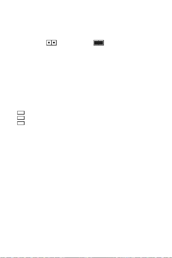
15
JBAT1 CMOS ( BIOS)
CMOS
CMOS
CMOS
BIOS
BIOS
1.
2. JBAT1 5-10
3. JBAT1
4.
EZ LED LED
LED
CPU — CPU CPU
DRAM — DRAM DRAM
VGA — GPU GPU
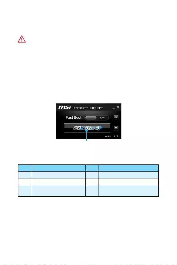
16 BIOS
BIOS
BIOS
y
BIOS BIOS
HELP BIOS
y
BIOS
BIOS
y Press DEL key to enter Setup Menu, F11 to enter Boot Menu
Delete
y MSI FAST BOOT GO2BIOS
BIOS
Click on GO2BIOS
F1 F4 CPU
F5 Memory-Z F6
F10 * F12 USB
( FAT/ FAT32 )
* F10

17
BIOS BIOS
BIOS
BIOS
BIOS
y BIOS F6
y CMOS
BIOS CMOS
BIOS
M-FLASH BIOS
MSI BIOS BIOS USB
BIOS
1. USB
2. POST Del BIOS
3. BIOS > M-FLASH > Select one file to update BIOS and ME BIOS
BIOS
4. 100%
Live Update 6 BIOS
BIOS
1. MSI LIVE UPDATE 6
2.
3. MB BIOS
4. MB BIOS BIOS
5. Windows
BIOS
6. 100%

18
Windows® 7/ 8.1/ 10
1.
2. Windows® 7/ 8.1/ 10
Windows® 7 USB USB
3.
4. Windows® 8.1/ 10 Windows® 7 Advanced >
Windows OS Configuration > Windows 7 Installation
Windows® 7 USB USB USB
5. (POST) F11
6.
7. Press any key to boot from CD or DVD…
8. Windows® 7/ 8.1/ 10
1. Windows® 7/ 8.1/ 10
2. MSI®
3.
4.
5.
6.
7.
1. MSI®
2.
3.
4.
5.
6.
7.
8.
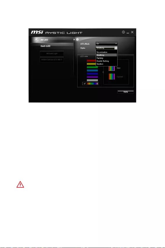
19
MYSTIC LIGHT
MYSTIC LIGHT LED
yAll LED ( LED) — LED
yEach LED ( LED) — LED
yLED effects (LED ) — LED
yStyles () — LED
yLED color (LED ) — LED (
)
yApply Button () — LED
yBIOS Breathing ()
y MYSTIC LIGHT No
animation ()MYSTIC LIGHT
BIOS LED
MYSTIC LIGHT No animation
()
y
MYSTIC LIGHT
y
Flashing()Double Flashing() Random()
DOS Breathing ().

20 NOTE
NOTE

1
< 1>
…………………………………………………………………………. 2
…………………………………………………………………………………………………… 3
I/O ……………………………………………………………………………………… 6
LANLED ……………………………………………………………………………..6
…………………………………………………………………………..7
CPU …………………………………………………………………………………………..8
DIMM …………………………………………………………………………………………9
PCI_E1~3: PCIe ……………………………………………………………………9
SATA1~4: SATA 6Gb/s …………………………………………………………….10
JFP1JFP2: …………………………………………………….10
JPWR1~2: …………………………………………………………………….. 11
JUSB1~2: USB 2.0 ………………………………………………………………… 11
JUSB3: USB 3.1 Gen1 …………………………………………………………….12
JAUD1: ……………………………………………………..12
JCOM1: ………………………………………………………….. 12
CPUFANSYSFAN1~2: …………………………………………………..13
JTPM1: TPM ………………………………………………………….14
JCI1: ………………………………………………………..14
JBAT1: CMOS (BIOS ) …………………………………………….15
EZ Debug LED: LED …………………………………………….15
BIOS ………………………………………………………………………………………. 16
BIOS ………………………………………………………………….16
BIOS ……………………………………………………………………………………..17
BIOS ………………………………………………………………………..17
……………………………………………………………………………. 18
Windows® 7/ 8.1/ 10 …………………………………………………………18
……………………………………………………………………….18
………………………………………………………………….18
MYSTIC LIGHT ……………………………………………………………………………………..19
MSI® H110M PRO-VD PLUS/ H110M PRO-VH PLUS
BIOS

2
y(ESD)PC
y
y
y (ESD)
ESD
y
y
PC
y
PC
yPC
yPC PC
y
y
y
y
y
y
PC
y60OC (140OF)
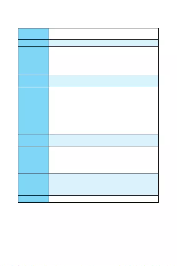
3
CPU LGA11516Intel® Core™ i3/i5/i7 Intel®
Pentium® Celeron®
Intel® H110
yDDR4 232GB
DDR4 2133 MHz
y
ynon-ECC, un-buffered
yIntel® Extreme Memory Profile (XMP)
yPCIe 3.0 x16 x1
yPCIe 2.0 x1 x2
yH110M PRO-VH PLUS
VGA x12048×1536@50Hz,
2048×1280@60Hz, 1920×1200@60Hz
HDMI™ x1 4096×2160@24Hz,
2560×1600@60Hz
yH110M PRO-VD PLUS
VGA x12048×1536@50Hz,
2048×1280@60Hz, 1920×1200@60Hz
DVI-D x11920×1200@60Hz
Intel® H110
ySATA 6Gb/s 4
USB
yIntel® H110
USB 3.1 Gen1 (SuperSpeed USB) x4 ( 2
USB 2)
USB 2.0 (High-speed USB) x6 ( 2
USB 4)
yRealtek® ALC887
y7.1 HD *
* HD 7.1
LAN Realtek® RTL8111H Gigabit LAN x1

4
yPS/2 x1
yPS/2 x1
yUSB 3.1 Gen1 x2
yHDMI™ x1 (H110M PRO-VH PLUS)
yDVI-D x1 (H110M PRO-VD PLUS)
yVGA x1
yLAN (RJ45) x1
yUSB 2.0 x2
y x3
y24ATX x1
y4ATX 12V x1
ySATA 6Gb/s x4
yUSB 2.0 x2 (4USB 2.0 )
yUSB 3.1 Gen1 x1 (2USB 3.1 Gen1
)
y4CPU x1
y4 x1
y x1
y x2
yTPM x1
y x1
y x1
yCMOS x1
I/O
NUVOTON NCT5563D
yCPU/
yCPU/
yCPU/
yMicro-ATX
y8.9 in. x 6.8 in. (22.6 cm x 17.3 cm)
BIOS
y64 Mb x1
yUEFI AMI BIOS
yACPI 5.0, PnP 1.0a, SM BIOS 2.8
y

5
y
yCOMMAND CENTER
yLIVE UPDATE 6
yFAST BOOT
ySUPER CHARGER
yM-CLOUD
yRAMDISK
yIntel® Small Business Basics
yNETWORK GENIE
yIntel® Extreme Tuning
yNorton™ Security
yGoogle Chrome™,Google Toolbar, Google Drive
yCPU-Z
yMYSTIC LIGHT
MSI
yCLICK BIOS
yCOMMAND CENTER
yRAMDISK
ySURPER CHARGER
yFAST BOOT
yLIVE UPDATE 6
yM-CLOUD
yMYSTIC LIGHT
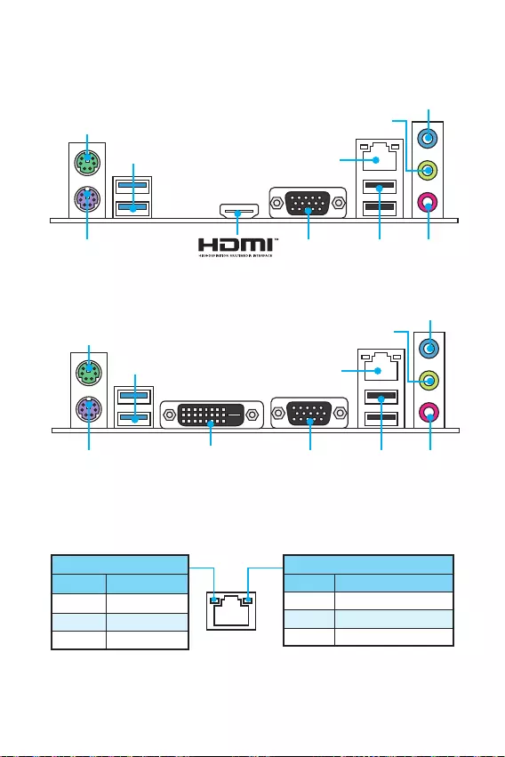
6I/O
I/O
DVI-D
H110M PRO-VD PLUS
PS/2
LAN
USB 3.1 Gen1
USB 2.0
VGAPS/2
H110M PRO-VH PLUS
/LED
Off
LED
Off 10 Mbps
100 Mbps
1 Gbps
LANLED
PS/2
LAN
USB 3.1 Gen1
VGAPS/2
USB 2.0
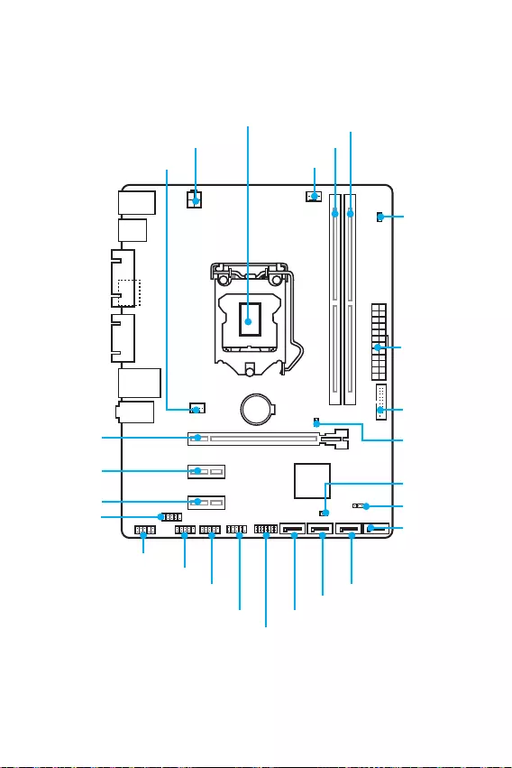
7
I/O
BAT1
DVI- D(optional)
HDMI(optional)
CPUFAN
JPWR2
PCI_E1
PCI_E2
PCI_E3
DIMM1
SYSFAN1
DIMM2
JUSB3
JFP1
JUSB1
SATA1
JFP2
JUSB2
JPWR1
EZ Debug LED
JCI1
SATA2
SATA3
SATA4
JTPM1
JBAT1
JCOM1
CPU
JAUD1
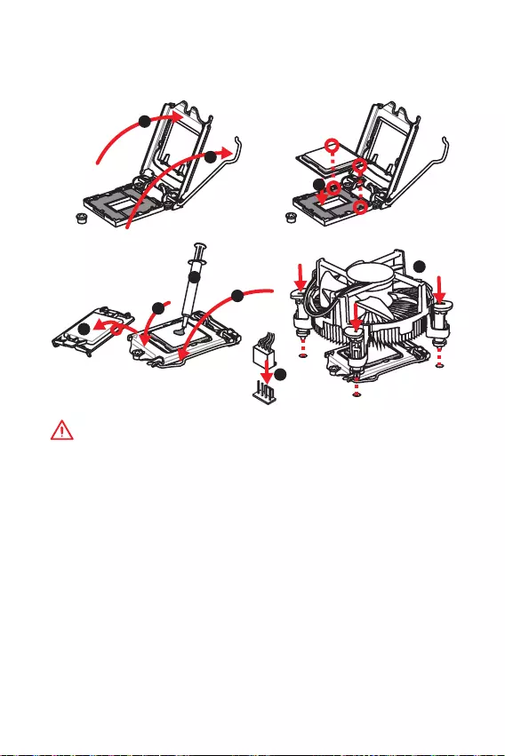
8
CPU
CPUCPU
y
CPU
y
CPUCPU CPU
CPU CPU
y
CPU CPUCPU
y
CPUCPU
y
CPUCPU
CPU
CPUCPU
y
CPUCPU
y
CPUCPUCPU
1
4
6
5
78
9
3
2
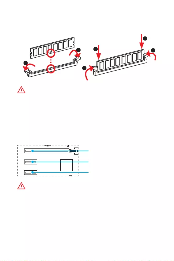
9
DIMM
DIMM
y
y
32bitWindows OS4GB
4GB64bit
Windows OS
PCI_E1~3: PCIe
BAT1
DVI- D(optional)
HDMI(optional)
PCI_E1: PCIe 3.0 x16
PCI_E2: PCIe 2.0×1
PCI_E3: PCIe 2.0×1
BIOS
1
12
3
3
2
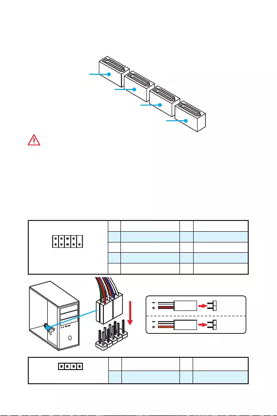
10
SATA1~4: SATA 6Gb/s
SATA 6Gb/s
SATA
SATA3
SATA2
SATA4
SATA1
y
SATA 90
y
SATA
JFP1JFP2:
LED
1
2 10
9
JFP1
1 HDD LED + 2 Power LED +
3 HDD LED — 4 Power LED —
5 Reset Switch 6 Power Switch
7 Reset Switch 8 Power Switch
9 Reserved 10 No Pin
1
JFP2
1 Speaker — 2 Buzzer +
3 Buzzer — 4 Speaker +
HDD LED
RESET SW
HDD LED HDD LED —
HDD LED +
POWER LED —
POWER LED +
POWER LED
JFP1
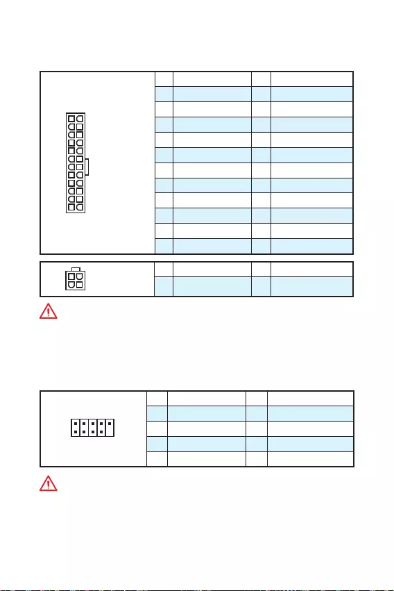
11
JPWR1~2:
ATX
24
131
12
JPWR1
1 +3.3V 13 +3.3V
2 +3.3V 14 -12V
3 Ground 15 Ground
4 +5V 16 PS-ON#
5 Ground 17 Ground
6 +5V 18 Ground
7 Ground 19 Ground
8 PWR OK 20 Res
9 5VSB 21 +5V
10 +12V 22 +5V
11 +12V 23 +5V
12 +3.3V 24 Ground
3
2 1
4JPWR2
1 Ground 3 +12V
2 Ground 4 +12V
ATX
JUSB1~2: USB 2.0
USB 2.0
1
2 10
9
1VCC 2VCC
3 USB0- 4 USB1-
5 USB0+ 6 USB1+
7 Ground 8 Ground
9 No Pin 10 NC
y
VCC
y
USB iPadiPhoneiPod MSI® SUPER CHARGER
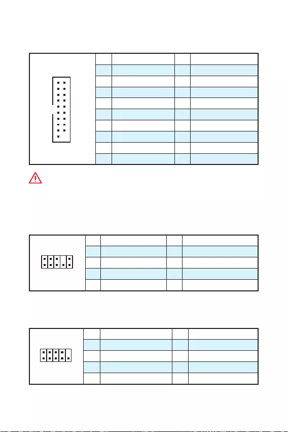
12
JUSB3: USB 3.1 Gen1
USB 3.1 Gen1
1
10 11
20
1Power 11 USB2.0+
2 USB3_RX_DN 12 USB2.0-
3 USB3_RX_DP 13 Ground
4 Ground 14 USB3_TX_C_DP
5 USB3_TX_C_DN 15 USB3_TX_C_DN
6 USB3_TX_C_DP 16 Ground
7 Ground 17 USB3_RX_DP
8 USB2.0- 18 USB3_RX_DN
9 USB2.0+ 19 Power
10 Ground 20 No Pin
JAUD1:
1
2 10
9
1 MIC L 2 Ground
3 MIC R 4 NC
5 Head Phone R 6 MIC Detection
7 SENSE_SEND 8 No Pin
9 Head Phone L 10 Head Phone Detection
JCOM1:
1
2 10
9
1 DCD 2 SIN
3 SOUT 4 DTR
5 Ground 6 DSR
7 RTS 8 CTS
9 RI 10 No Pin
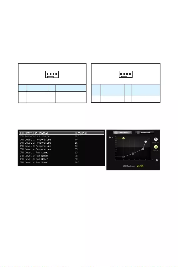
13
CPUFANSYSFAN1~2:
PWM () PWM
12V
3 (Non-PWM)PWM
100%
1
CPUFAN
1 Ground 2 +12V
3 Sense 4 Speed Control
Signal
1
SYSFAN1
1 Ground 2 Voltage
Control
3 Sense 4 NC
PWM
2 BIOS > Advanced > Hardware Monitor
COMMAND CENTER
COMMAND CENTER
BIOS Hardware Monitor
COMMAND CENTERCPU
BIOS > Advanced > Hardware Monitor
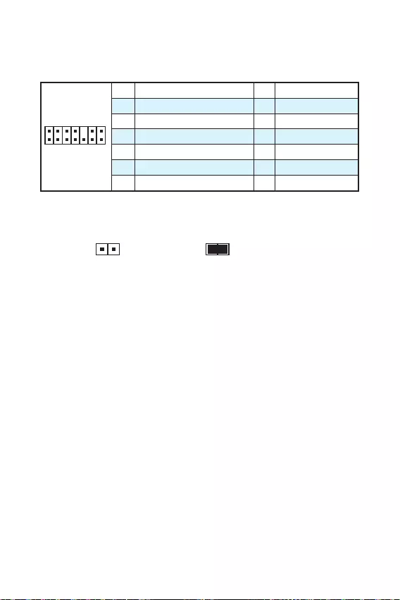
14
JTPM1: TPM
TPM (Trusted Platform Module)TPM
1
2 14
13
1 LPC Clock 2 3V Standby power
3 LPC Reset 4 3.3V Power
5 LPC address & data pin0 6 Serial IRQ
7 LPC address & data pin1 8 5V Power
9 LPC address & data pin2 10 No Pin
11 LPC address & data pin3 12 Ground
13 LPC Frame 14 Ground
JCI1:
()
1. JCI1/
2.
3. BIOS > Security > Chassis Intrusion Configuration
4. Chassis IntrusionEnabled
5. F10Enter
Yes
6.
1. BIOS >Security > Chassis Intrusion Configuration
2. Chassis IntrusionReset
3. F10Enter
Yes

15
JBAT1: CMOS (BIOS)
CMOS
CMOS
()
CMOS /
BIOS
BIOS
1. PC
2. JBAT15-10
3. JBAT1
4.
EZ Debug LED: LED
LED
CPU — CPU
DRAM — DRAM
VGA — GPU
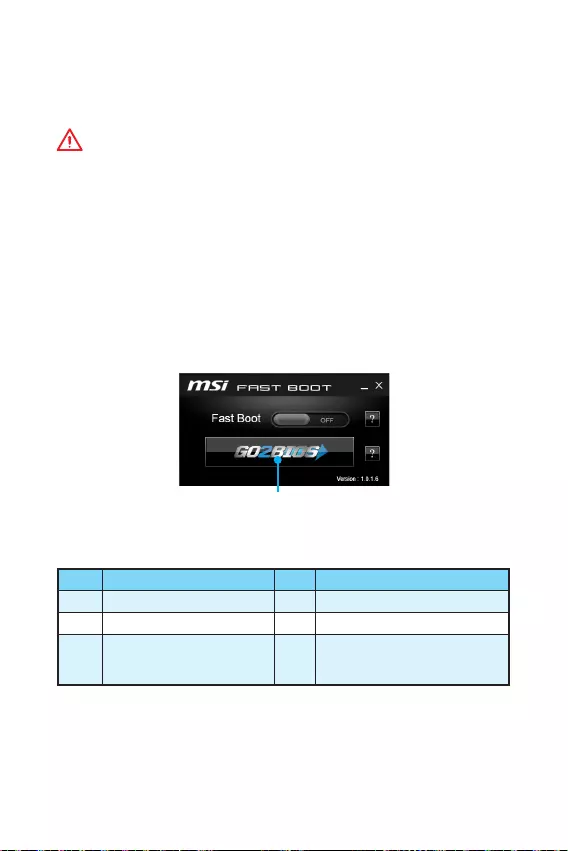
16 BIOS
BIOS
BIOS
BIOS
y
BIOSBIOS
BIOS
HELP
y
BIOS
BIOS
yPress DEL key to enter Setup Menu, F11 to enter Boot Menu
Delete
yWindowsMSI FAST BOOT GO2BIOS
OKBIOS
GO2BIOS
F1 F4 CPU
F5 Memory-Z F6 optimized defaults
F10 * F12
USB
(FAT/ FAT32
)
* F10Yes
No

17
BIOS BIOS
BIOS
BIOSBIOS
yBIOS <F6>optimized defaults
y CMOS
BIOS COMS
BIOS
M-FLASHBIOS
:
MSIWEB BIOS USB
BIOS :
1. BIOS USB USB
2. POST<Delete> BIOS
3. BIOS > M-FLASH > Select one file to update BIOS and MEBIOS
BIOS
4.
Live Update 6BIOS
:
LAN
BIOS :
1. MSI LIVE UPDATE 6
2.
3. MB BIOS
4. MB BIOS BIOS
5. Next In Windows modeNextStart
BIOS
6.

18
Windows® 7/ 8.1/ 10
1. PC
2. Windows® 7/ 8.1/ 10
: Windows 7 USB
USB
3. PCRestart
4. Windows® 8.1/ 10Windows 7
BIOSAdvanced > Windows OS Configuration >
Windows 7 InstallationF10
PC
: Windows 7USB/USBI/O
USB
5. POST (Power-On Self Test)F11
6.
7. Press any key to boot from CD or DVD…
(Enter )
8. Windows® 7/ 8.1/ 10
1. Windows® 7/ 8.1/ 10
2. MSI®
3.
4. Install
5.
6. OK
7. PC
1. MSI®
2.
3. Utilities
4.
5. Install
6.
7. OK
8. PC
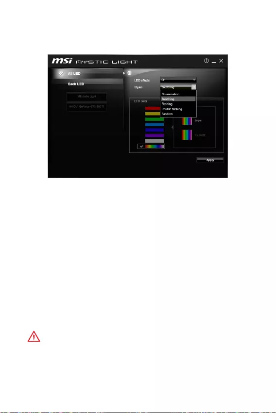
19
MYSTIC LIGHT
MYSTIC LIGHT LED
yAll LED — LED
yEach LED — LED
yLED effects — LED/
yStyles — LED
yLED color () — LED
yApply Button — LEDStyles
yBIOS LEDBreathing
yMYSTIC LIGHT OS
No animationMYSTIC LIGHTApply
MYSTIC LIGHTBIOSOS
: OSMYSTIC LIGHT No animation
y
MYSTIC LIGHT LED
y
LED «Flashing», «Double Flashing», «Random» DOS
LED breathing

20 Note
Note
i
< 1> Regulatory Notices
FCC Compliance Statement
Note: This equipment has been tested and found
to comply with the limits for a Class B digital
device, pursuant to part 15 of the FCC Rules.
These limits are designed to provide reasonable
protection against harmful interference in
a residential installation. This equipment
generates, uses and can radiate radio frequency
energy and, if not installed and used in
accordance with the instructions, may cause
harmful interference to radio communications.
However, there is no guarantee that interference
will not occur in a particular installation. If this
equipment does cause harmful interference
to radio or television reception, which can be
determined by turning the equipment off and
on, the user is encouraged to try to correct the
interference by one or more of the following
measures:
yReorient or relocate the receiving antenna.
yIncrease the separation between the
equipment and receiver.
yConnect the equipment into an outlet on a
circuit different from that to which the receiver
is connected.
yConsult the dealer or an experienced radio/TV
technician for help.
Caution: Changes or modifications not
expressly approved by the party responsible for
compliance could void the users authority to
operate the equipment.
Tested to comply with FCC standards FOR
HOME OR OFFICE USE
This device complies with part 15 of the FCC
Rules. Operation is subject to the following two
conditions:
(1) This device may not cause harmful
interference, and (2) this device must accept any
interference received, including interference
that may cause undesired operation.
CE Conformity
Hereby, Micro-Star International CO.,
LTD declares that this device is in
compliance with the essential safety
requirements and other relevant
provisions set out in the European Directive.
C-Tick Compliance
B ( )
(B)
,
.
B
VCCI-B
Battery Information
European Union:
Batteries, battery packs, and
accumulators should not be
disposed of as unsorted household
waste. Please use the public
collection system to return, recycle,
or treat them in compliance with the
local regulations.
Taiwan:
For better environmental protection,
waste batteries should be collected
separately for recycling or special
disposal.
California, USA:
The button cell battery may contain
perchlorate material and requires
special handling when recycled or
disposed of in California.
For further information please visit:
http://www.dtsc.ca.gov/hazardouswaste/
perchlorate/
CAUTION: There is a risk of explosion, if battery
is incorrectly replaced.
Replace only with the same or equivalent type
recommended by the manufacturer.
Chemical Substances Information
In compliance with chemical substances
regulations, such as the EU REACH Regulation
(Regulation EC No. 1907/2006 of the European
Parliament and the Council), MSI provides
the information of chemical substances in
products at:
http://www.msi.com/html/popup/csr/evmtprtt_
pcm.html
Regulatory Notices

ii Regulatory Notices
WEEE (Waste Electrical and
Electronic Equipment) Statement
ENGLISH
To protect the global environment and as an
environmentalist, MSI must remind you that…
Under the European Union (“EU”) Directive on
Waste Electrical and Electronic Equipment,
Directive 2002/96/EC, which takes effect on
August 13, 2005, products of “electrical and
electronic equipment” cannot be discarded as
municipal wastes anymore, and manufacturers
of covered electronic equipment will be
obligated to take back such products at the end
of their useful life. MSI will comply with the
product take back requirements at the end of
life of MSI-branded products that are sold into
the EU. You can return these products to local
collection points.
DEUTSCH
Hinweis von MSI zur Erhaltung und Schutz
unserer Umwelt
Gemäß der Richtlinie 2002/96/EG über
Elektro- und Elektronik-Altgeräte dürfen
Elektro- und Elektronik-Altgeräte nicht
mehr als kommunale Abfälle entsorgt
werden. MSI hat europaweit verschiedene
Sammel- und Recyclingunternehmen
beauftragt, die in die Europäische Union
in Verkehr gebrachten Produkte, am Ende
seines Lebenszyklus zurückzunehmen. Bitte
entsorgen Sie dieses Produkt zum gegebenen
Zeitpunkt ausschliesslich an einer lokalen
Altgerätesammelstelle in Ihrer Nähe.
FRANÇAIS
En tant qu’écologiste et afin de protéger
l’environnement, MSI tient à rappeler ceci…
Au sujet de la directive européenne (EU) relative
aux déchets des équipement électriques et
électroniques, directive 2002/96/EC, prenant
effet le 13 août 2005, que les produits
électriques et électroniques ne peuvent être
déposés dans les décharges ou tout simplement
mis à la poubelle. Les fabricants de ces
équipements seront obligés de récupérer
certains produits en fin de vie. MSI prendra en
compte cette exigence relative au retour des
produits en fin de vie au sein de la communauté
européenne. Par conséquent vous pouvez
retourner localement ces matériels dans les
points de collecte.
РУССКИЙ
Компания MSI предпринимает активные
действия по защите окружающей среды,
поэтому напоминаем вам, что….
В соответствии с директивой Европейского
Союза (ЕС) по предотвращению загрязнения
окружающей среды использованным
электрическим и электронным оборудованием
(директива WEEE 2002/96/EC), вступающей
в силу 13 августа 2005 года, изделия,
относящиеся к электрическому и электронному
оборудованию, не могут рассматриваться
как бытовой мусор, поэтому производители
вышеперечисленного электронного
оборудования обязаны принимать его для
переработки по окончании срока службы. MSI
обязуется соблюдать требования по приему
продукции, проданной под маркой MSI на
территории EC, в переработку по окончании
срока службы. Вы можете вернуть эти изделия
в специализированные пункты приема.
ESPAÑOL
MSI como empresa comprometida con la
protección del medio ambiente, recomienda:
Bajo la directiva 2002/96/EC de la Unión
Europea en materia de desechos y/o equipos
electrónicos, con fecha de rigor desde el 13 de
agosto de 2005, los productos clasificados como
“eléctricos y equipos electrónicos” no pueden
ser depositados en los contenedores habituales
de su municipio, los fabricantes de equipos
electrónicos, están obligados a hacerse cargo
de dichos productos al termino de su período de
vida. MSI estará comprometido con los términos
de recogida de sus productos vendidos en la
Unión Europea al final de su periodo de vida.
Usted debe depositar estos productos en el
punto limpio establecido por el ayuntamiento
de su localidad o entregar a una empresa
autorizada para la recogida de estos residuos.
NEDERLANDS
Om het milieu te beschermen, wil MSI u eraan
herinneren dat….
De richtlijn van de Europese Unie (EU) met
betrekking tot Vervuiling van Electrische en
Electronische producten (2002/96/EC), die op
13 Augustus 2005 in zal gaan kunnen niet meer
beschouwd worden als vervuiling. Fabrikanten
van dit soort producten worden verplicht om
producten retour te nemen aan het eind van
hun levenscyclus. MSI zal overeenkomstig de
richtlijn handelen voor de producten die de
merknaam MSI dragen en verkocht zijn in de EU.
Deze goederen kunnen geretourneerd worden
op lokale inzamelingspunten.
SRPSKI
Da bi zaštitili prirodnu sredinu, i kao preduzeće
koje vodi računa o okolini i prirodnoj sredini, MSI
mora da vas podesti da…
Po Direktivi Evropske unije (“EU”) o odbačenoj
ekektronskoj i električnoj opremi, Direktiva
2002/96/EC, koja stupa na snagu od 13. Avgusta
2005, proizvodi koji spadaju pod “elektronsku i
električnu opremu” ne mogu više biti odbačeni
kao običan otpad i proizvođači ove opreme
biće prinuđeni da uzmu natrag ove proizvode
na kraju njihovog uobičajenog veka trajanja.
MSI će poštovati zahtev o preuzimanju ovakvih
proizvoda kojima je istekao vek trajanja, koji
imaju MSI oznaku i koji su prodati u EU. Ove
proizvode možete vratiti na lokalnim mestima
za prikupljanje.

iii
Regulatory Notices Regulatory Notices
POLSKI
Aby chronić nasze środowisko naturalne oraz
jako firma dbająca o ekologię, MSI przypomina,
że…
Zgodnie z Dyrektywą Unii Europejskiej (“UE”)
dotyczącą odpadów produktów elektrycznych
i elektronicznych (Dyrektywa 2002/96/EC),
która wchodzi w życie 13 sierpnia 2005, tzw.
“produkty oraz wyposażenie elektryczne i
elektroniczne “ nie mogą być traktowane jako
śmieci komunalne, tak więc producenci tych
produktów będą zobowiązani do odbierania ich w
momencie gdy produkt jest wycofywany z użycia.
MSI wypełni wymagania UE, przyjmując produkty
(sprzedawane na terenie Unii Europejskiej)
wycofywane z użycia. Produkty MSI będzie
można zwracać w wyznaczonych punktach
zbiorczych.
TÜRKÇE
Çevreci özelliğiyle bilinen MSI dünyada çevreyi
korumak için hatırlatır:
Avrupa Birliği (AB) Kararnamesi Elektrik
ve Elektronik Malzeme Atığı, 2002/96/EC
Kararnamesi altında 13 Ağustos 2005 tarihinden
itibaren geçerli olmak üzere, elektrikli ve
elektronik malzemeler diğer atıklar gibi
çöpe atılamayacak ve bu elektonik cihazların
üreticileri, cihazların kullanım süreleri bittikten
sonra ürünleri geri toplamakla yükümlü
olacaktır. Avrupa Birliği’ne satılan MSI markalı
ürünlerin kullanım süreleri bittiğinde MSI
ürünlerin geri alınması isteği ile işbirliği
içerisinde olacaktır. Ürünlerinizi yerel toplama
noktalarına bırakabilirsiniz.
ČESKY
Záleží nám na ochraně životního prostředí —
společnost MSI upozorňuje…
Podle směrnice Evropské unie (“EU”) o likvidaci
elektrických a elektronických výrobků 2002/96/
EC platné od 13. srpna 2005 je zakázáno
likvidovat “elektrické a elektronické výrobky”
v běžném komunálním odpadu a výrobci
elektronických výrobků, na které se tato
směrnice vztahuje, budou povinni odebírat
takové výrobky zpět po skončení jejich životnosti.
Společnost MSI splní požadavky na odebírání
výrobků značky MSI, prodávaných v zemích
EU, po skončení jejich životnosti. Tyto výrobky
můžete odevzdat v místních sběrnách.
MAGYAR
Annak érdekében, hogy környezetünket
megvédjük, illetve környezetvédőként fellépve az
MSI emlékezteti Önt, hogy …
Az Európai Unió („EU”) 2005. augusztus
13-án hatályba lépő, az elektromos és
elektronikus berendezések hulladékairól szóló
2002/96/EK irányelve szerint az elektromos
és elektronikus berendezések többé nem
kezelhetőek lakossági hulladékként, és az ilyen
elektronikus berendezések gyártói kötelessé
válnak az ilyen termékek visszavételére
azok hasznos élettartama végén. Az MSI
betartja a termékvisszavétellel kapcsolatos
követelményeket az MSI márkanév alatt az EU-n
belül értékesített termékek esetében, azok
élettartamának végén. Az ilyen termékeket a
legközelebbi gyűjtőhelyre viheti.
ITALIANO
Per proteggere l’ambiente, MSI, da sempre
amica della natura, ti ricorda che….
In base alla Direttiva dell’Unione Europea (EU)
sullo Smaltimento dei Materiali Elettrici ed
Elettronici, Direttiva 2002/96/EC in vigore dal 13
Agosto 2005, prodotti appartenenti alla categoria
dei Materiali Elettrici ed Elettronici non possono
più essere eliminati come rifiuti municipali: i
produttori di detti materiali saranno obbligati
a ritirare ogni prodotto alla fine del suo ciclo di
vita. MSI si adeguerà a tale Direttiva ritirando
tutti i prodotti marchiati MSI che sono stati
venduti all’interno dell’Unione Europea alla fine
del loro ciclo di vita. È possibile portare i prodotti
nel più vicino punto di raccolta
JIS C 0950
JIS C 0950 200671
http://www.msi.com/html/popup/csr/
cemm_jp.html
http://tw.msi.com/html/popup/csr_tw/
cemm_jp.html
India RoHS
This product complies with the “India
E-waste (Management and Handling) Rule
2011” and prohibits use of lead, mercury,
hexavalent chromium, polybrominated
biphenyls or polybrominated diphenyl ethers
in concentrations exceeding 0.1 weight % and
0.01 weight % for cadmium, except for the
exemptions set in Schedule 2 of the Rule.
Türkiye EEE yönetmeliği
Türkiye Cumhuriyeti: EEE Yönetmeliğine
Uygundur
Україна обмеження на наявність
небезпечних речовин
Обладнання відповідає вимогам Технічного
регламенту щодо обмеження використання
деяких небезпечних речовин в електричному
та електронному обладнані, затвердженого
постановою Кабінету Міністрів України від 3
грудня 2008 № 1057.
Vit Nam RoHS
K t ngày 01/12/2012, tt c các sn phm
do công ty MSI sn xut tuân th Thông t s
30/2011/TT-BCT quy đnh tm thi v gii hn
hàm lng cho phép ca mt s hóa cht đc
hi có trong các sn phm đin, đin t”
iv Regulatory Notices
(Pb)
(Hg)
(Cd)
(Cr(VI))
(PBB)
(PBDE)
* X O O O O O
** X O O O O O
X O O O O O
X O O O O O
SJ/T 11364
O: GB/T 26572
X: GB/T 26572
RoHS
* :
**
Environmental Policy
yThe product has been designed
to enable proper reuse of parts
and recycling and should not be
thrown away at its end of life.
yUsers should contact the local
authorized point of collection for
recycling and disposing of their end-of-life
products.
yVisit the MSI website and locate a nearby
distributor for further recycling information.
Users may also reach us at gpcontdev@msi.
com for information regarding proper Disposal,
Take-back, Recycling, and Disassembly of MSI
products.
Copyright
Micro-Star Intl Co.,Ltd.
Copyright © 2016 All rights reserved.
The material in this document is the intellectual
property of Micro-Star Intl Co.,Ltd. We take
every care in the preparation of this document,
but no guarantee is given as to the correctness
of its contents. Our products are under continual
improvement and we reserve the right to make
changes without notice.
Technical Support
If a problem arises with your system and no
solution can be obtained from the user guide,
please contact your place of purchase or local
distributor. Alternatively, please try the following
help resources for further guidance.
yVisit the MSI website for technical guide,
BIOS updates, driver updates, and other
information: http://www.msi.com
yRegister your product at: http://register.
msi.com
Trademark Recognition
All product names used in this manual are the
properties of their respective owners and are
acknowledged.
Revision History
Version 1.0, 2016/03, First release.
MSI H110M PRO-VD PLUS Motherboard PDF User Guides and Manuals for Free Download: Found (1) Manuals for MSI H110M PRO-VD PLUS Device Model (Operation & User’s Manual)
MSI H110M PRO-VD PLUS Operation & User’s Manual
Details:
- Manufacturer: MSI
- Product Name/ID: MSI H110M PRO-VD PLUS / #2389863
- Category: Motherboard
- File Path: msi/h110m-pro-vd-plus_2389863.pdf
- Last Updated: 14 Apr 2025
- Description: This manual for MSI H110M PRO-VD PLUS is designed to provide complete guidance on using your device, with step-by-step installation instructions, operational tips, and maintenance advice.
- Document Type: User Manual
- Pages: 164
Download PDF
Read Online
The MSI H110M PRO-VD PLUS motherboard is an entry-level motherboard that strikes a balance between affordability and functionality, making it an excellent choice for budget-conscious PC builders. Designed for Intel’s 6th and 7th generation processors, this micro-ATX motherboard stands out in the crowded market due to its reliable performance, practical design, and supportive features.
One of the standout features of the MSI H110M PRO-VD PLUS is its compatibility with a range of components. The motherboard supports Intel’s LGA 1151 socket, allowing users to install various processors, from the more budget-friendly i3 models to the more powerful i7 variants. This flexibility is further complemented by support for up to 32GB of DDR4 RAM, which is ample for the average consumer and offers future-proofing for those looking to upgrade over time.
When considering a new motherboard, the layout and connectivity options are vital. The MSI H110M PRO-VD PLUS provides a good selection of ports, including:
- Two USB 3.1 Gen1 ports for high-speed data transfer
- Four USB 2.0 ports for additional peripherals
- HDMI and DVI-D video outputs to connect to various monitors
- Realtek ALC887 audio codec for clear sound quality
- Gigabit LAN for reliable internet connections
Furthermore, the board features a PCI Express x16 slot for a dedicated graphics card, which makes it easy for users to enhance their gaming or multimedia experience. For users who prefer a more integrated solution, the H110M PRO-VD PLUS also supports Intel HD Graphics, making it possible to run basic applications and enjoy casual gaming without a discrete GPU.
Building capabilities extend further with the board supporting M.2 and SATA III storage options. This allows for rapid data retrieval and storage, making it a suitable choice for users who prefer SSDs for their operating systems or applications. The board’s ability to accommodate larger storage solutions lays the groundwork for extensive media libraries or demanding software applications.
MSI is known for its durability, and the H110M PRO-VD PLUS is no exception. With its Military Class 4 components, the motherboard is built to last. This ensures that users can rely on their systems for years without worrying about component failure. The use of high-quality capacitors and other components bolsters the board’s longevity and performance stability.
In terms of ease of use, the H110M PRO-VD PLUS offers a straightforward BIOS setup, which is user-friendly and accessible, even for those building a PC for the first time. It has clear navigation, making adjustments to system settings easy and intuitive. MSI’s Click BIOS 5 provides a seamless experience, enabling overclocking and fine-tuning with ease.
Lastly, MSI has included a good warranty and customer support with the H110M PRO-VD PLUS. This shows that the company stands behind its products and is ready to assist users in their endeavors. While the board is not heavy on extravagant features, its reliability, quality, and solid performance make it a valuable option for anyone seeking to build a budget-friendly PC.
In conclusion, the MSI H110M PRO-VD PLUS motherboard is a practical choice. With its compatibility, solid build, and user-friendly design, it accommodates various users’ needs while maintaining affordability. Whether you are building a home office setup, a casual gaming rig, or simply looking for a reliable computing solution, the H110M PRO-VD PLUS can deliver. It’s a worthy contender in the entry-level motherboard market.

1
< 1> Contents
Contents
Safety Information ………………………………………………………………………………. 2
Specifications ………………………………………………………………………………………3
Rear I/O Panel …………………………………………………………………………………….6
LAN Port LED Status Table ……………………………………………………………………..6
Overview of Components ……………………………………………………………………..7
CPU Socket ……………………………………………………………………………………………8
DIMM Slots ……………………………………………………………………………………………9
PCI_E1~3: PCIe Expansion Slots………………………………………………………………9
SATA1~4: SATA 6Gb/s Connectors ………………………………………………………….10
JFP1, JFP2: Front Panel Connectors ………………………………………………………10
JPWR1~2: Power Connectors ………………………………………………………………..11
JUSB1~2: USB 2.0 Connectors ………………………………………………………………11
JUSB3: USB 3.1 Gen1 Connector ……………………………………………………………12
JAUD1: Front Audio Connector ………………………………………………………………12
JCOM1: Serial Port Connector ……………………………………………………………….12
CPUFAN, SYSFAN1: Fan Connectors ………………………………………………………13
JTPM1: TPM Module Connector……………………………………………………………..14
JCI1: Chassis Intrusion Connector …………………………………………………………14
JBAT1: Clear CMOS (Reset BIOS) Jumper ……………………………………………….15
EZ Debug LED: Debug LED indicators …………………………………………………….15
BIOS Setup ……………………………………………………………………………………….. 16
Entering BIOS Setup……………………………………………………………………………..16
Resetting BIOS …………………………………………………………………………………….17
Updating BIOS ……………………………………………………………………………………..17
Software Description ………………………………………………………………………….18
Installing Windows
®
7/ 8.1/ 10 ……………………………………………………………….18
Installing Drivers ………………………………………………………………………………….18
Installing Utilities …………………………………………………………………………………18
MYSTIC LIGHT ……………………………………………………………………………………..19
Thank you for purchasing the MSI
®
motherboard H110M
PRO-VD PLUS/ H110M PRO-VH PLUS. This User Guide gives
information about board layout, component overview and
BIOS setup.

2
Safety Information
Safety Information
y The components included in this package are prone to damage from electrostatic
discharge (ESD). Please adhere to the following instructions to ensure successful
computer assembly.
y Ensure that all components are securely connected. Loose connections may cause
the computer to not recognize a component or fail to start.
y Hold the motherboard by the edges to avoid touching sensitive components.
y It is recommended to wear an electrostatic discharge (ESD) wrist strap when
handling the motherboard to prevent electrostatic damage. If an ESD wrist strap
is not available, discharge yourself of static electricity by touching another metal
object before handling the motherboard.
y Store the motherboard in an electrostatic shielding container or on an anti-static
pad whenever the motherboard is not installed.
y Before turning on the computer, ensure that there are no loose screws or metal
components on the motherboard or anywhere within the computer case.
y Do not boot the computer before installation is completed. This could cause
permanent damage to the components as well as injury to the user.
y If you need help during any installation step, please consult a certified computer
technician.
y Always turn off the power supply and unplug the power cord from the power outlet
before installing or removing any computer component.
y Keep this user guide for future reference.
y Keep this motherboard away from humidity.
y Make sure that your electrical outlet provides the same voltage as is indicated on
the PSU, before connecting the PSU to the electrical outlet.
y Place the power cord such a way that people can not step on it. Do not place
anything over the power cord.
y All cautions and warnings on the motherboard should be noted.
y If any of the following situations arises, get the motherboard checked by service
personnel:
Liquid has penetrated into the computer.
The motherboard has been exposed to moisture.
The motherboard does not work well or you can not get it work according to user
guide.
The motherboard has been dropped and damaged.
The motherboard has obvious sign of breakage.
y Do not leave this motherboard in an environment above 60C (140F), it may
damage the motherboard.

3
Safety Information Specifications
Specifications
CPU
Supports 6th Gen Intel
®
Core
™
i3/i5/i7 processors, and Intel
®
Pentium
®
and Celeron
®
processors for Socket LGA1151
Chipset Intel
®
H110 Chipset
Memory
y 2x DDR4 memory slots, support up to 32GB
Supports DDR4 2133 MHz
y Dual channel memory architecture
y Supports non-ECC, un-buffered memory
y Supports Intel
®
Extreme Memory Profile (XMP)
Expansion Slots
y 1x PCIe 3.0 x16 slot
y 2x PCIe 2.0 x1 slots
Onboard
Graphics
y H110M PRO-VH PLUS
1x VGA port, supports a maximum resolution of
2048×1536@50Hz, 2048×1280@60Hz, 1920×1200@60Hz
1x HDMI
™
port, supports a maximum resolution of
4096×2160@24Hz, 2560×1600@60Hz
y H110M PRO-VD PLUS
1x VGA port, supports a maximum resolution of
2048×1536@50Hz, 2048×1280@60Hz, 1920×1200@60Hz
1x DVI-D port, supports a maximum resolution of
1920×1200@60Hz
Storage
Intel
®
H110 Chipset
y 4x SATA 6Gb/s ports
USB
y Intel
®
H110 Chipset
4x USB 3.1 Gen1 (SuperSpeed USB) ports (2 ports on the
back panel, 2 ports available through the internal USB
connector)
6x USB 2.0 (High-speed USB) ports (2 ports on the back
panel, 4 ports available through the internal USB connectors)
Audio
y Realtek
®
ALC887 Codec
y 7.1-Channel High Definition Audio*
* The HD audio module in the front panel of the chassis is
necessary for 7.1-channel audio output.
LAN 1x Realtek
®
RTL8111H Gigabit LAN controller
Continued on next page

4
Specifications
Continued from previous page
Back Panel
Connectors
y 1x PS/2 mouse port
y 1x PS/2 keyboard port
y 2x USB 3.1 Gen1 ports
y 1x HDMI
™
port (H110M PRO-VH PLUS)
y 1x DVI-D port (H110M PRO-VD PLUS)
y 1x VGA port
y 1x LAN (RJ45) port
y 2x USB 2.0 ports
y 3x audio jacks
Internal
Connectors
y 1x 24-pin ATX main power connector
y 1x 4-pin ATX 12V power connector
y 4x SATA 6Gb/s connectors
y 2x USB 2.0 connectors (supports additional 4 USB 2.0 ports)
y 1x USB 3.1 Gen1 connector (supports additional 2 USB 3.1
Gen1 ports)
y 1x 4-pin CPU fan connector
y 1x 4-pin system fan connector
y 1x Front panel audio connector
y 2x Front panel connectors
y 1x TPM module connector
y 1x Serial Port connector
y 1x Chassis Intrusion connector
y 1x Clear CMOS jumper
I/O Controller NUVOTON NCT5563D Controller Chip
Hardware
Monitor
y CPU/System temperature detection
y CPU/System fan speed detection
y CPU/System fan speed control
Form Factor
y Micro-ATX Form Factor
y 8.9 in. x 6.8 in. (22.6 cm x 17.3 cm)
BIOS Features
y 1x 64 Mb flash
y UEFI AMI BIOS
y ACPI 5.0, PnP 1.0a, SM BIOS 2.8
y Multi-language
Continued on next page

5
Specifications Specifications
Continued from previous page
Software
y Drivers
y COMMAND CENTER
y LIVE UPDATE 6
y FAST BOOT
y SUPER CHARGER
y M-CLOUD
y RAMDISK
y Intel
®
Small Business Basics
y NETWORK GENIE
y Intel
®
Extreme Tuning Utility
y Norton™ Security
y Google Chrome™,Google Toolbar, Google Drive
y CPU-Z
y MYSTIC LIGHT
MSI Exclusive
Features
y CLICK BIOS
y COMMAND CENTER
y RAMDISK
y SURPER CHARGER
y FAST BOOT
y LIVE UPDATE 6
y M-CLOUD
y MYSTIC LIGHT

8
Overview of Components
CPU Socket
Please install the CPU into the CPU socket as shown below.
Important
y
Always unplug the power cord from the power outlet before installing or removing
the CPU.
y
Please retain the CPU protective cap after installing the processor. MSI will deal
with Return Merchandise Authorization (RMA) requests if only the motherboard
comes with the protective cap on the CPU socket.
y
When installing a CPU, always remember to install a CPU heatsink. A CPU heatsink
is necessary to prevent overheating and maintain system stability.
y
Confirm that the CPU heatsink has formed a tight seal with the CPU before booting
your system.
y
Overheating can seriously damage the CPU and motherboard. Always make sure
the cooling fans work properly to protect the CPU from overheating. Be sure to
apply an even layer of thermal paste (or thermal tape) between the CPU and the
heatsink to enhance heat dissipation.
y
Whenever the CPU is not installed, always protect the CPU socket pins by covering
the socket with the plastic cap.
y
If you purchased a separate CPU and heatsink/ cooler, Please refer to the
documentation in the heatsink/ cooler package for more details about installation.
1
4
6
5
7
8
9
3
2

9
Overview of Components Overview of Components
DIMM Slots
Please install the memory module into the DIMM slot as shown below.
Important
y
Due to chipset resource usage, the available capacity of memory will be a little less
than the amount of installed.
y
Please note that the maximum capacity of addressable memory is 4GB or less
for 32-bit Windows OS due to the memory address limitation. Therefore, we
recommended that you to install 64-bit Windows OS if you want to install more than
4GB memory on the motherboard.
PCI_E1~3: PCIe Expansion Slots
BAT1
DVI- D(optional)
HDMI(optional)
PCI_E1: PCIe 3.0 x16 slot
PCI_E2: PCIe 2.0×1 slot
PCI_E3: PCIe 2.0×1 slot
Important
When adding or removing expansion cards, always turn off the power supply and
unplug the power supply power cable from the power outlet. Read the expansion
cards documentation to check for any necessary additional hardware or software
changes.
1
1
2
3
3
2

10
Overview of Components
SATA1~4: SATA 6Gb/s Connectors
These connectors are SATA 6Gb/s interface ports. Each connector can connect to one
SATA device.
SATA3
SATA2
SATA4
SATA1
Important
y
Please do not fold the SATA cable at a 90-degree angle. Data loss may result during
transmission otherwise.
y
SATA cable has identical plugs on either sides of the cable. However, it is
recommended that the flat connector be connected to the motherboard for space
saving purposes.
JFP1, JFP2: Front Panel Connectors
These connectors connect to the switches and LEDs on the front panel.
1
2 10
9
JFP1
1 HDD LED + 2 Power LED +
3 HDD LED — 4 Power LED —
5 Reset Switch 6 Power Switch
7 Reset Switch 8 Power Switch
9 Reserved 10 No Pin
1
JFP2
1 Speaker — 2 Buzzer +
3 Buzzer — 4 Speaker +
HDD LED
RESET SW
HDD LED
HDD LED —
HDD LED +
POWER LED —
POWER LED +
POWER LED
JFP1

11
Overview of Components Overview of Components
JPWR1~2: Power Connectors
These connectors allow you to connect an ATX power supply.
24
131
12
JPWR1
1 +3.3V 13 +3.3V
2 +3.3V 14 -12V
3 Ground 15 Ground
4 +5V 16 PS-ON#
5 Ground 17 Ground
6 +5V 18 Ground
7 Ground 19 Ground
8 PWR OK 20 Res
9 5VSB 21 +5V
10 +12V 22 +5V
11 +12V 23 +5V
12 +3.3V 24 Ground
3
2 1
4
JPWR2
1 Ground 3 +12V
2 Ground 4 +12V
Important
Make sure that all the power cables are securely connected to a proper ATX power
supply to ensure stable operation of the motherboard.
JUSB1~2: USB 2.0 Connectors
These connectors allow you to connect USB 2.0 ports on the front panel.
1
2 10
9
1 VCC 2 VCC
3 USB0- 4 USB1-
5 USB0+ 6 USB1+
7 Ground 8 Ground
9 No Pin 10 NC
Important
y
Note that the VCC and Ground pins must be connected correctly to avoid possible
damage.
y
In order to recharge your iPad,iPhone and iPod through USB ports, please install
MSI
®
SUPER CHARGER utility.

12
Overview of Components
JUSB3: USB 3.1 Gen1 Connector
This connector allows you to connect USB 3.1 Gen1 ports on the front panel.
1
10 11
20
1 Power 11 USB2.0+
2 USB3_RX_DN 12 USB2.0-
3 USB3_RX_DP 13 Ground
4 Ground 14 USB3_TX_C_DP
5 USB3_TX_C_DN 15 USB3_TX_C_DN
6 USB3_TX_C_DP 16 Ground
7 Ground 17 USB3_RX_DP
8 USB2.0- 18 USB3_RX_DN
9 USB2.0+ 19 Power
10 Ground 20 No Pin
Important
Note that the Power and Ground pins must be connected correctly to avoid possible
damage.
JAUD1: Front Audio Connector
This connector allow you to connect audio jacks on the front panel.
1
2 10
9
1 MIC L 2 Ground
3 MIC R 4 NC
5 Head Phone R 6 MIC Detection
7 SENSE_SEND 8 No Pin
9 Head Phone L 10 Head Phone Detection
JCOM1: Serial Port Connector
This connector allows you to connect the optional serial port with bracket.
1
2 10
9
1 DCD 2 SIN
3 SOUT 4 DTR
5 Ground 6 DSR
7 RTS 8 CTS
9 RI 10 No Pin

13
Overview of Components Overview of Components
CPUFAN, SYSFAN1: Fan Connectors
Fan connectors can be classified as PWM (Pulse Width Modulation) Mode and Voltage
Mode. PWM Mode fan connectors provide constant 12V output and adjust fan speed
with speed control signal. Voltage Mode fan connectors control fan speed by changing
voltage. Therefore, when you plug a 3-pin (Non-PWM) fan to a PWM Mode fan
connector, the fan speed will be always maintained at 100%, and that could be noisy.
1
CPUFAN
1 Ground 2 +12V
3 Sense 4
Speed Control
Signal
1
SYSFAN1
1 Ground 2
Voltage
Control
3 Sense 4 NC
PWM Mode fan connector Voltage Mode fan connector
Controlling the fan speed
There are two ways to manage fan speed. One is to go to BIOS > Advanced >
Hardware Monitor. The other is to use COMMAND CENTER application.
COMMAND CENTER
BIOS Hardware Monitor sub-menu allows you to set the temperature levels and the
corresponding fan speed levels.
COMMAND CENTER offers gradient points of the fan speed that allow you to adjust
fan speed in relation to CPU temperature.
BIOS > Advanced > Hardware Monitor

14
Overview of Components
JTPM1: TPM Module Connector
This connector is for TPM (Trusted Platform Module). Please refer to the TPM
security platform manual for more details and usages.
1
2 14
13
1 LPC Clock 2 3V Standby power
3 LPC Reset 4 3.3V Power
5 LPC address & data pin0 6 Serial IRQ
7 LPC address & data pin1 8 5V Power
9 LPC address & data pin2 10 No Pin
11 LPC address & data pin3 12 Ground
13 LPC Frame 14 Ground
JCI1: Chassis Intrusion Connector
This connector allows you to connect the chassis intrusion switch cable.
Normal
(default)
Trigger the chassis
intrusion event
Using chassis intrusion detector
1. Connect the JCI1 connector to the chassis intrusion switch/ sensor on the
chassis.
2. Close the chassis cover.
3. Go to BIOS > Security > Chassis Intrusion Configuration.
4. Set Chassis Intrusion to Enabled.
5. Press F10 to save and exit and then press the Enter key to select Yes.
6. Once the chassis cover is opened again, a warning message will be displayed on
screen when the computer is turned on.
Resetting the chassis intrusion warning
1. Go to BIOS > Security > Chassis Intrusion Configuration.
2. Set Chassis Intrusion to Reset.
3. Press F10 to save and exit and then press the Enter key to select Yes.

15
Overview of Components Overview of Components
JBAT1: Clear CMOS (Reset BIOS) Jumper
There is CMOS memory onboard that is external powered from a battery located on
the motherboard to save system configuration data. If you want to clear the system
configuration, set the jumper to clear the CMOS memory.
Keep Data
(default)
Clear CMOS/ Reset
BIOS
Resetting BIOS to default values
1. Power off the computer and unplug the power cord.
2. Use a jumper cap to short JBAT1 for about 5-10 seconds.
3. Remove the jumper cap from JBAT1.
4. Plug the power cord and power on the computer.
EZ Debug LED: Debug LED indicators
These LEDs indicate the status of the motherboard.
CPU — indicates CPU is not detected or fail.
DRAM — indicates DRAM is not detected or fail.
VGA — indicates GPU is not detected or fail.

16
BIOS Setup
BIOS Setup
The default settings offer the optimal performance for system stability in normal
conditions. You should always keep the default settings to avoid possible system
damage or failure booting unless you are familiar with BIOS.
Important
y
BIOS items are continuous update for better system performance. Therefore, the
description may be slightly different from the latest BIOS and should be held for
reference only. You could also refer to the HELP information panel for BIOS item
description.
y
The pictures in this chapter are for reference only and may vary from the product
you purchased.
Entering BIOS Setup
Please refer the following methods to enter BIOS setup.
y Press Delete key, when the Press DEL key to enter Setup Menu, F11 to enter Boot
Menu message appears on the screen during the boot process.
y Use MSI FAST BOOT application. Click on GO2BIOS button and choose OK. The
system will reboot and enter BIOS setup directly.
Click on GO2BIOS
Function key
Key Function Key Function
F1 General Help F4 Enter CPU Specifications menu
F5 Enter Memory-Z menu F6 Load optimized defaults
F10 Save Change and Reset* F12
Take a screenshot and save it
to USB flash drive (FAT/ FAT32
format only).
* When you press F10, a confirmation window which provides the modification
information appears. Select between Yes or No to confirm your choice.

17
BIOS Setup BIOS Setup
Resetting BIOS
You might need to restore the default BIOS setting to solve certain problems. There
are several ways to reset BIOS:
y Go to BIOS and press F6 to load optimized defaults.
y Short the Clear CMOS jumper on the motherboard.
Important
Please refer to the Clear CMOS Jumper section for resetting BIOS.
Updating BIOS
Updating BIOS with M-FLASH
Before updating:
Please download the latest BIOS file that matches your motherboard model from MSI
website. And then save the BIOS file into the USB flash drive.
Updating BIOS:
1. Insert the USB flash drive that contains the update file into the computer.
2. Reboot the system, and then press Del key to enter the BIOS Setup during POST.
3. Go to BIOS > M-FLASH > Select one file to update BIOS and ME, select a BIOS file
to perform the BIOS update process.
4. After the flashing process is 100% complete, the system will reboot.
Updating the BIOS with Live Update 6
Before updating:
Make sure the LAN driver is already installed and the internet connection is set
properly.
Updating BIOS:
1. Install and launch MSI LIVE UPDATE 6.
2. Select Manual scan.
3. Check MB BIOS box and click on Scan button.
4. Select the MB BIOS and click on
icon to download and install the latest BIOS
file.
5. Click Next and choose In Windows mode. And then click Next and Start to start
updating BIOS.
6. After the flashing process is 100% completed, the system will restart
automatically.

18
Software Description
Software Description
Installing Windows
®
7/ 8.1/ 10
1. Power on the computer.
2. Insert the Windows
®
7/ 8.1/ 10 disc into your optical drive.
Note: Due to chipset limitation, during the Windows
®
7 installation process, USB
optical drives or USB pen drives are not supported.
3. Press the Restart button on the computer case.
4. For windows
®
8.1/ 10, skip this step. For Windows
®
7, access the BIOS menu
Advanced > Windows OS Configuration > Windows 7 Installation and set the item
to enabled, save changes and restart.
Note: It is suggested to plug in your USB Keyboard/USB Mouse to the leftmost
USB port when installing Windows
®
7.
5. Press F11 key during the computer POST (Power-On Self Test) to get into Boot
Menu.
6. Select your optical drive from the Boot Menu.
7. Press any key when screen shows Press any key to boot from CD or DVD…
message.
8. Follow the instructions on the screen to install Windows
®
7/ 8.1/ 10.
Installing Drivers
1. Start up your computer in Windows
®
7/ 8.1/ 10.
2. Insert MSI
®
Driver Disc into your optical drive.
3. The installer will automatically appear and it will find and list all necessary
drivers.
4. Click Install button.
5. The software installation will then be in progress, after it has finished it will
prompt you to restart.
6. Click OK button to finish.
7. Restart your computer.
Installing Utilities
Before you install utilities, you must complete drivers installation.
1. Insert MSI
®
Driver Disc into your optical drive.
2. The installer will automatically appear.
3. Click Utilities tab.
4. Select the utilities you want to install.
5. Click Install button.
6. The utilities installation will then be in progress, after it has finished it will
prompt you to restart.
7. Click OK button to finish.
8. Restart your computer.

19
Software Description Software Description
MYSTIC LIGHT
MYSTIC LIGHT allows you to control LED lights on your motherboard and graphics
cards.
y All LED — controls all LEDs on your motherboard and graphics cards.
y Each LED — separately controls each segment of LEDs on your motherboard and
graphics cards.
y LED effects — switches LEDs on or off.
y Styles — selects the LED style from the drop-down list.
y LED color (optional) — allows you to change the LED color. This option depends on
the motherboard you purchased.
y Apply Button — applies Styles settings to LEDs.
Audio line control
y Default Audio line setting in BIOS is Breathing.
y After installing MYSTIC LIGHT and reboot to OS, the default style of Audio line will
switch to No animation. Once we change Audio line style in MYSTIC LIGHT and click
Apply, the software will immediately re-program the Audio line style in both BIOS
and OS.
Note: Audio line styles will change to No animation if user shuts down the MYSTIC
LIGHT in OS.
Important
y
It is recommended to control Audio line style by MYSTIC LIGHT.
y
Audio line will be in Breathing mode under DOS when you select the following
styles Flashing, Double Flashing and Random.
Introduction of MSI Motheboard H110M Pro VD-Plus
The MSI H110M Pro VD-Plus is a budget-friendly motherboard that supports Intel 6th and 7th Gen processors. This motherboard is perfect for building a small form factor gaming PC or a home theater PC. With a price point below $60, it’s an excellent choice for those on a tight budget. The motherboard was launched in May 2017 and has been a popular choice among budget-conscious consumers ever since.
Specifications
CPU
-
Supports 6th Gen Intel Core i3/i5/i7 processors, and Intel Pentium and Celeron processors for Socket LGA1151
Chipset
-
Intel H110 Chipset
Memory
-
2x DDR4 memory slots, support up to 32GB
-
Supports DDR4 2133 MHz
-
Dual channel memory architecture
-
Supports non-ECC, un-buffered memory
-
Supports Intel Extreme Memory Profile (XMP)
Expansion Slots
-
1x PCIe 3.0 x16 slot
-
2x PCIe 2.0 x1 slots
Onboard Graphics
-
H110M PRO-VH PLUS
-
1x VGA port, supports a maximum resolution of 2048×1536@50Hz, 2048×1280@60Hz, 1920×1200@60Hz
-
1x HDMI™ port, supports a maximum resolution of 4096×2160@24Hz, 2560×1600@60Hz
-
-
H110M PRO-VD PLUS
-
1x VGA port, supports a maximum resolution of 2048×1536@50Hz, 2048×1280@60Hz, 1920×1200@60Hz
-
1x DVI-D port, supports a maximum resolution of 1920×1200@60Hz
-
Storage
-
Intel H110 Chipset
-
4x SATA 6Gb/s ports
USB
-
Intel H110 Chipset
-
4x USB 3.1 Gen1 (SuperSpeed USB) ports (2 ports on the back panel, 2 ports available through the internal USB connector)
-
6x USB 2.0 (High-speed USB) ports (2 ports on the back panel, 4 ports available through the internal USB connectors)
-
Audio
-
Realtek ALC887 Codec
-
7.1-Channel High Definition Audio*
-
The HD audio module in the front panel of the chassis is needed to support a 7.1-channel audio output.
-
LAN
-
1x Realtek® RTL8111H Gigabit LAN controller
Back Panel Connectors
-
1x PS/2 mouse port
-
1x PS/2 keyboard port
-
2x USB 3.1 Gen1 ports
-
1x HDMI port (H110M PRO-VH PLUS)
-
1x DVI-D port (H110M PRO-VD PLUS)
-
1x VGA port
-
1x LAN (RJ45) port
-
2x USB 2.0 ports
-
3x audio jacks
Internal Connectors
-
1x 24-pin ATX main power connector
-
1x 4-pin ATX 12V power connector
-
4x SATA 6Gb/s connectors
-
2x USB 2.0 connectors (supports additional 4 USB 2.0 ports)
-
1x USB 3.1 Gen1 connector (supports additional 2 USB 3.1 Gen1 ports)
-
1x 4-pin CPU fan connector
-
1x 4-pin system fan connector
-
1x Front panel audio connector
-
2x Front panel connectors
-
1x TPM module connector
-
1x Serial port connector
-
1x Chassis Intrusion connector
-
1x Clear CMOS jumper
I/O Controller
-
NUVOTON NCT55363D Controller Chip
Hardware Monitor
-
CPU/System temperature detection
-
CPU/System fan speed detection
-
CPU/System fan speed control
Form Factor
-
Micro-ATX Form Factor
-
8.9 in. x 6.6 in. (22.6 cm x 17.3 cm)
BIOS Features
-
1x 64 Mb flash
-
UEFI AMI BIOS
-
ACPI 5.0, PnP 1.0a, SM BIOS 2.8
-
Multi-language
Software
-
Drivers
-
COMMAND CENTER
-
LIVE UPDATE 6
-
FAST BOOT
-
SUPER CHARGER
-
M-CLOUD
-
RAMDISK
-
Intel Small Business Basics
-
NETWORK GENIE
-
Intel Extreme Tuning Utility
-
Norton™ Security
-
Google Chrome, Google Toolbar, Google Drive
-
CPU-Z
-
MYSTIC LIGHT
MSI Exclusive Features
-
CLICK BIOS
-
COMMAND CENTER
-
RAMDISK
-
SUPER CHARGER
-
FAST BOOT
-
LIVE UPDATE 6
-
M-CLOUD
-
MYSTIC LIGHT
Overview of Components
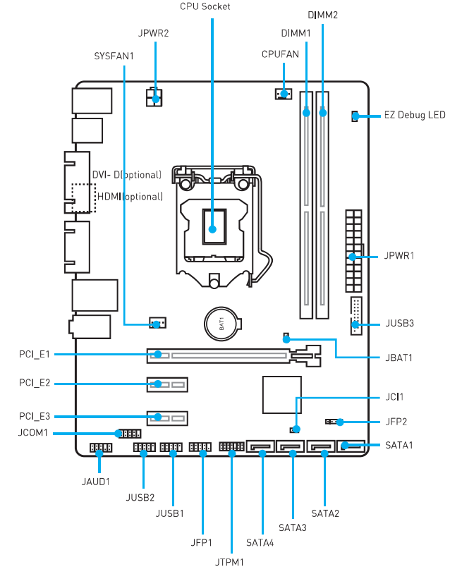
Rear I/O Panel
H110M PRO-VH PLUS
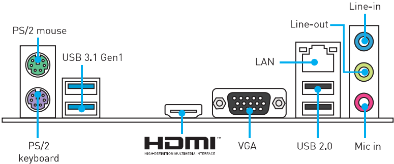
H110M PRO-VD PLUS
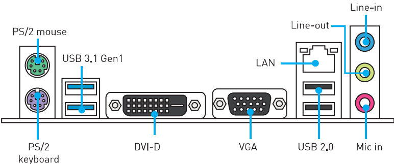
LAN Port LED Status Table
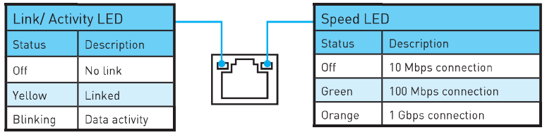
CPU Socket
Please install the CPU into the CPU socket as shown below.
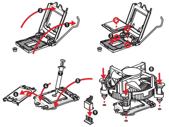
-
Always unplug the power cord from the power outlet before installing or removing the CPU.
-
Please retain the CPU protective cap after installing the processor. MSI will deal with Return Merchandise Authorization (RMA) requests if only the motherboard comes with the protective cap on the CPU socket.
-
When installing a CPU, always remember to install a CPU heatsink. A CPU heatsink is necessary to prevent overheating and maintain system stability.
-
Confirm that the CPU heatsink has formed a tight seal with the CPU before booting your system.
-
Overheating can seriously damage the CPU and motherboard. Always make sure the cooling fans work properly to protect the CPU from overheating. Be sure to apply an even layer of thermal paste (or thermal tape) between the CPU and the heatsink to enhance heat dissipation.
-
Whenever the CPU is not installed, always protect the CPU socket pins by covering the socket with the plastic cap.
-
If you purchased a separate CPU and heatsink/cooler, please refer to the documentation in the heatsink/cooler package for more details about installation.
DIMM Slots
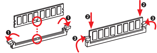
Please install the memory module into the DIMM slot as shown below.
Important
-
Due to chipset resource usage, the available capacity of memory will be a little less than the amount installed.
-
Please note that the maximum capacity of addressable memory is 4GB or less for 32-bit Windows OS due to memory address limitation. Therefore, we recommend that you install 64-bit Windows OS if you want to install more than 4GB memory on the motherboard.
PCI_E1-3: PCIe Expansion Slots
When adding or removing expansion cards, always turn off the power supply and unplug the power supply power cable from the power outlet. Read the expansion card’s documentation to check for any necessary additional hardware or software changes.
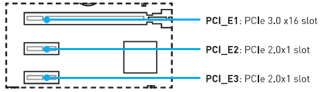
SATA1-4: SATA 6Gb/s Connectors
These connectors are SATA 6Gb/s interface ports. Each connector can connect to one SATA device.
-
Please do not fold the SATA cable at a 90-degree angle. Data loss may result during transmission otherwise.
-
SATA cable has identical plugs on either side of the cable. However, it is recommended that the flat connector be connected to the motherboard for space-saving purposes.
JFP1, JFP2: Front Panel Connectors
These connectors connect to the switches and LEDs on the front panel.
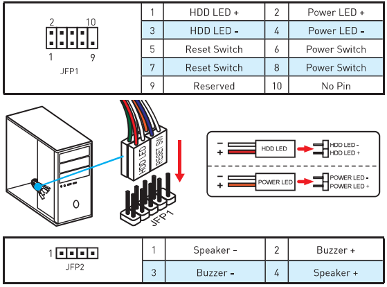
JPWR1-2: Power Connectors
These connectors allow you to connect an ATX power supply.
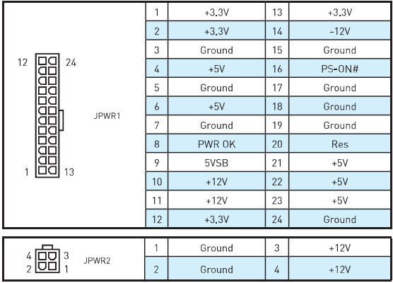
Important: Make sure that all the power cables are securely connected to a proper ATX power supply to ensure stable operation of the motherboard.
JUSB1-2: USB 2.0 Connectors
These connectors allow you to connect USB 2.0 ports on the front panel.
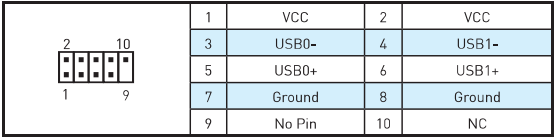
-
Note that the VCC and Ground pins must be connected correctly to avoid possible damage.
-
In order to recharge your iPad, iPhone, and iPod through USB ports, please install MSI® SUPER CHARGER utility.
JUSB3: USB 3.1 Gen1 Connector
This connector allows you to connect USB 3.1 Gen1 ports on the front panel.
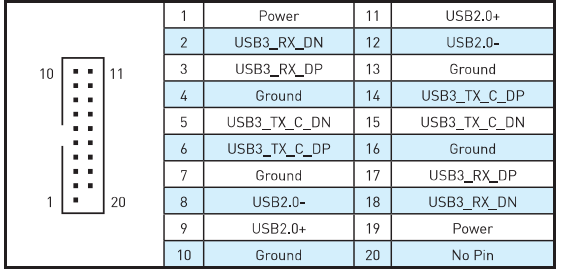
Important: Note that the Power and Ground pins must be connected correctly to avoid possible damage.
JAUD1: Front Audio Connector
This connector allows you to connect audio jacks on the front panel.
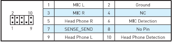
JCOM1: Serial Port Connector
This connector allows you to connect the optional serial port with a bracket.
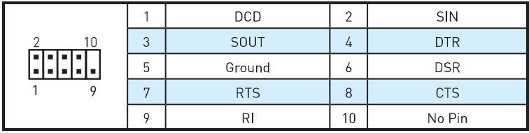
CPUFAN, SYSFAN1: Fan Connectors
Fan connectors can be classified as PWM (Pulse Width Modulation) Mode and Voltage Mode. PWM Mode fan connectors provide constant 12V output and adjust fan speed with a speed control signal. Voltage Mode fan connectors control fan speed by changing voltage. Therefore, when you plug a 3-pin (Non-PWM) fan into a PWM Mode fan connector, the fan speed will always be maintained at 100%, and that could be noisy.
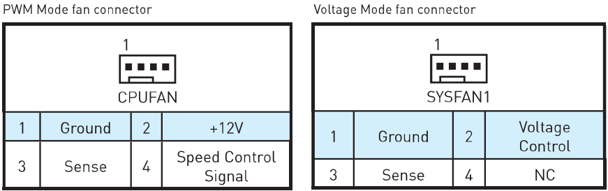
Controlling the fan speed
There are two ways to manage fan speed. One is to go to BIOS> Advanced> Hardware Monitor. The other is to use the COMMAND CENTER application.
-
BIOS Hardware Monitor sub-menu allows you to set the temperature levels and the corresponding fan speed levels.
-
COMMAND CENTER offers gradient points of the fan speed that allow you to adjust fan speed in relation to CPU temperature.

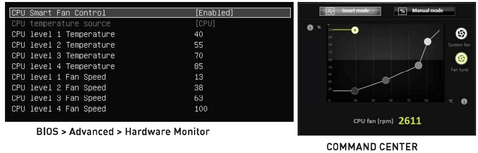
JTPM1: TPM Module Connector
This connector is for TPM (Trusted Platform Module). Please refer to the TPM security platform manual for more details and usages.
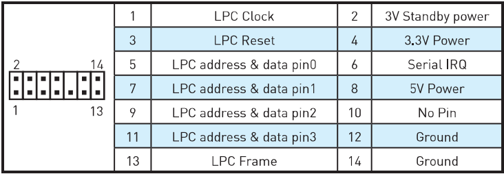
JCI1: Chassis Intrusion Connector
This connector allows you to connect the chassis intrusion switch cable.
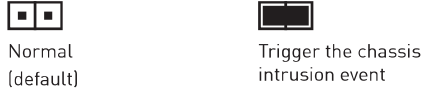
Using chassis intrusion detector
-
Connect the JCI1 connector to the chassis intrusion switch/sensor on the chassis.
-
Close the chassis cover.
-
Go to BIOS > Security > Chassis Intrusion Configuration.
-
Set Chassis Intrusion to Enabled.
-
Press F10 to save and exit and then press the Enter key to select Yes.
-
Once the chassis cover is opened again, a warning message will be displayed on the screen when the computer is turned on.
Resetting the chassis intrusion warning
-
Go to BIOS > Security > Chassis Intrusion Configuration.
-
Set Chassis Intrusion to Reset.
-
Press F10 to save and exit and then press the Enter key to select Yes.
JBAT1: Clear CMOS (Reset BIOS) Jumper
There is CMOS memory onboard that is externally powered from a battery located on the motherboard to save system configuration data. If you want to clear the system configuration, set the jumper to clear the CMOS memory.
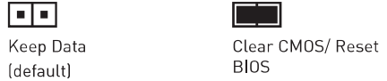
Resetting BIOS to default values
-
Power off the computer and unplug the power cord.
-
Use a jumper cap to short JBAT1 for about 5-10 seconds.
-
Remove the jumper cap from JBAT1.
-
Plug the power cord and power on the computer.
EZ Debug LED: Debug LED indicators
These LEDs indicate the status of the motherboard.
-
CPU — indicates CPU is not detected or failed.
-
DRAM — indicates DRAM is not detected or failed.
-
VGA — indicates GPU is not detected or failed.
Description
The MSI H110M Pro VD-Plus features the H110 chipset and supports Intel 6th and 7th Gen processors with an LGA 1151 socket. It has two DDR4 memory slots that support up to 32GB of memory with speeds of up to 2400MHz. The motherboard has one PCIe x16 slot for graphics cards and two PCIe x1 slots for expansion cards. For storage, it has four SATA III ports and one M.2 slot. The motherboard has HDMI, DVI, and VGA ports for video output and supports up to 4K resolution. It also has USB 2.0 and USB 3.0 ports for connectivity. The audio section is powered by the Realtek ALC887 codec and supports 7.1 channel surround sound. The MSI H110M Pro VD-Plus also features MSI’s Military Class 4 components for improved durability and stability.
BIOS Setup
The default settings offer the optimal performance for system stability in normal conditions. You should always keep the default settings to avoid possible system damage or failure booting unless you are familiar with BIOS.
Important
-
BIOS items are continuously updated for better system performance. Therefore, the description may be slightly different from the latest BIOS and should be held for reference only. You could also refer to the HELP information panel for BIOS item descriptions.
-
The pictures in this chapter are for reference only and may vary from the product you purchased.
Entering BIOS Setup
Please refer to the following methods to enter BIOS setup.
-
Press the Delete key when the «Press DEL key to enter Setup Menu, F11 to enter Boot Menu» message appears on the screen during the boot process.
-
Use the MSI FAST BOOT application. Click on the GO2BIOS button and choose OK. The system will reboot and enter BIOS setup directly.
Function key
When you press F10, a confirmation window which provides the modification information appears. Select between Yes or No to confirm your choice.
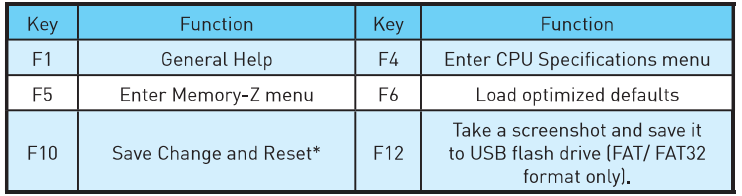
MSI Motheboard H110M Pro VD-Plus Resetting BIOS
You might need to restore the default BIOS setting to solve certain problems. There are several ways to reset BIOS:
-
Go to BIOS and press F6 to load optimized defaults.
-
Short the Clear CMOS jumper on the motherboard.
Important: Please refer to the Clear CMOS Jumper section for resetting BIOS.
Updating BIOS
Updating BIOS with M-FLASH
Before updating: Please download the latest BIOS file that matches your motherboard model from the MSI website. Then save the BIOS file onto a USB flash drive.
-
Insert the USB flash drive that contains the update file into the computer.
-
Reboot the system, and then press the Del key to enter the BIOS Setup during POST.
-
Go to BIOS > M-FLASH > Select one file to update BIOS and ME, select a BIOS file to perform the BIOS update process.
-
After the flashing process is 100% complete, the system will reboot.
Updating the BIOS with Live Update 6
Before updating: Make sure the LAN driver is already installed and the internet connection is set properly.
Updating BIOS
-
Install and launch MSI LIVE UPDATE 6.
-
Select Manual scan.
-
Check the MB BIOS box and click on the Scan button.
-
Select the MB BIOS and click on the download icon to download and install the latest BIOS file.
-
Click Next and choose In Windows mode. Then click Next and Start to start updating BIOS.
-
After the flashing process is 100% complete, the system will restart automatically.
Software Description
Installing Windows 7/ 8.1/ 10
-
Power on the computer.
-
Insert the Windows7/ 8.1/ 10 disc into your optical drive.
Note: Due to chipset limitation, during the Windows® 7 installation process, USB optical drives or USB pen drives are not supported. -
Press the Restart button on the computer case.
-
For Windows 8.1/ 10, skip this step. For Windows® 7, access the BIOS menu Advanced > Windows OS Configuration > Windows 7 Installation and set the item to enabled, save changes, and restart.
Note: It is suggested to plug in your USB Keyboard/USB Mouse to the leftmost USB port when installing Windows® 7. -
Press the F11 key during the computer POST (Power-On Self Test) to get into Boot Menu.
-
Select your optical drive from the Boot Menu.
-
Press any key when the screen shows «Press any key to boot from CD or DVD…» message.
-
Follow the instructions on the screen to install Windows® 7/ 8.1/ 10.
Installing Drivers
-
Start up your computer in Windows 7/ 8.1/ 10.
-
Insert MSI® Driver Disc into your optical drive.
-
The installer will automatically appear and it will find and list all necessary drivers.
-
Click the Install button.
-
The software installation will then be in progress; after it has finished, it will prompt you to restart.
-
Click OK button to finish.
-
Restart your computer.
Installing Utilities
Before you install utilities, you must complete drivers installation.
-
Insert MSI® Driver Disc into your optical drive.
-
The installer will automatically appear.
-
Click the Utilities tab.
-
Select the utilities you want to install.
-
Click the Install button.
-
The utilities installation will then be in progress; after it has finished, it will prompt you to restart.
-
Click the OK button to finish.
-
Restart your computer.
MYSTIC LIGHT
MYSTIC LIGHT allows you to control LED lights on your motherboard and graphics cards.
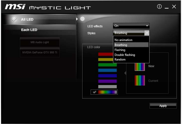
-
All LED — controls all LEDs on your motherboard and graphics cards.
-
Each LED — separately controls each segment of LEDs on your motherboard and graphics cards.
-
LED effects — switches LEDs on or off.
-
Styles — selects the LED style from the drop-down list.
-
LED color (optional) — allows you to change the LED color. This option depends on the motherboard you purchased.
-
Apply Button — applies Styles settings to LEDs.
Audio line control
-
Default Audio line setting in BIOS is Breathing.
-
After installing MYSTIC LIGHT and rebooting to OS, the default style of Audio line will switch to No animation. Once we change the Audio line style in MYSTIC LIGHT and click Apply, the software will immediately re-program the Audio line style in both BIOS and OS.
Note: Audio line styles will change to No animation if the user shuts down the MYSTIC LIGHT in OS.
Important
-
It is recommended to control the Audio line style by MYSTIC LIGHT.
-
Audio line will be in Breathing mode under DOS when you select the following styles: Flashing, Double Flashing, and Random.
MSI Motheboard H110M Pro VD-Plus Safety Information
-
The components included in this package are prone to damage from electrostatic discharge (ESD). Please adhere to the following instructions to ensure successful computer assembly.
-
Ensure that all components are securely connected. Loose connections may cause the computer to not recognize a component or fail to start.
-
Hold the motherboard by the edges to avoid touching sensitive components.
-
It is recommended to wear an electrostatic discharge (ESD) wrist strap when handling the motherboard to prevent electrostatic damage. If an ESD wrist strap is not available, discharge yourself of static electricity by touching another metal object before handling the motherboard.
-
Store the motherboard in an electrostatic shielding container or on an anti-static pad whenever the motherboard is not installed.
-
Before turning on the computer, ensure that there are no loose screws or metal components on the motherboard or anywhere within the computer case.
-
Do not boot the computer before installation is completed. This could cause permanent damage to the components as well as injury to the user.
-
If you need help during any installation step, please consult a certified computer technician.
-
Always turn off the power supply and unplug the power cord from the power outlet before installing or removing any computer component.
-
Keep this user guide for future reference.
-
Keep this motherboard away from humidity.
-
Make sure that your electrical outlet provides the same voltage as is indicated on the PSU, before connecting the PSU to the electrical outlet.
-
Place the power cord in such a way that people cannot step on it. Do not place anything over the power cord.
-
All cautions and warnings on the motherboard should be noted.
-
If any of the following situations arise, get the motherboard checked by service personnel:
-
Liquid has penetrated into the computer.
-
The motherboard has been exposed to moisture.
-
The motherboard does not work well or you cannot get it to work according to the user guide.
-
The motherboard has been dropped and damaged.
-
The motherboard has obvious signs of breakage.
-
-
Do not leave this motherboard in an environment above 60°C (140°F); it may damage the motherboard.
Troubleshooting
Common Problems and Solutions
- My graphics card is not detected: Make sure the graphics card is properly seated in the PCIe x16 slot and the power connectors are properly connected.
- My memory is not recognized: Make sure the memory modules are properly seated in the memory slots and are compatible with the motherboard.
- My system won’t boot: Make sure the power supply is properly connected and the power switch is turned on.
- My system is unstable: Make sure the memory modules are properly seated and the memory speeds are set correctly in the BIOS.
MSI H110M Pro VD-Plus Pros & Cons
Pros
- Affordable price point
- Supports Intel 6th and 7th Gen processors
- Two DDR4 memory slots
- HDMI, DVI, and VGA ports for video output
- M.2 slot for fast storage
Cons
- Limited PCIe expansion slots
- Only supports up to 2400MHz memory speeds
- No built-in Wi-Fi or Bluetooth
Customer Reviews about MSI Motheboard H110M Pro VD-Plus
Customers have generally praised the MSI H110M Pro VD-Plus for its affordability and reliability. Many users have reported that the motherboard is easy to install and has performed well in their systems. However, some users have reported issues with the audio section and the lack of Wi-Fi or Bluetooth connectivity.
SHDR-3448580-04 Aqua Hinged Shower Door Installation Instructions
FAQ: Types of Manuals and Their Contents
MSI H110M PRO-VD PLUS Manuals come in various types, each serving a specific purpose to help users effectively operate and maintain their devices. Here are the common types of MSI H110M PRO-VD PLUS User Guides and the information they typically include:
- User Manuals: Provide comprehensive instructions on how to use the device, including setup, features, and operation. They often include troubleshooting tips, safety information, and maintenance guidelines.
- Service Instructions: Designed for technicians and repair professionals, these manuals offer detailed information on diagnosing and repairing issues with the device. They include schematics, parts lists, and step-by-step repair procedures.
- Installation Guides: Focus on the installation process of the device, providing detailed instructions and diagrams for proper setup. They are essential for ensuring the device is installed correctly and safely.
- Maintenance Manuals: Provide guidance on routine maintenance tasks to keep the device in optimal condition. They cover cleaning procedures, part replacements, and regular servicing tips.
- Quick Start Guides: Offer a concise overview of the essential steps needed to get the device up and running quickly. They are ideal for users who need immediate assistance with basic setup and operation.
Each type of MSI H110M PRO-VD PLUS instruction is designed to address specific needs, ensuring users have the necessary information to use, maintain, and repair their devices effectively.
Related Instructions for MSI H110M PRO-VD PLUS:
1
X58M — Motherboard — Micro ATX
Operation & user’s manual #HNFM62: X58M — Motherboard — Micro ATX Motherboard Operation & user’s manual
104
637
109
2
Z87-G43 GAMING
55
1106
255
3
J-TX98 R2
Manual MSI J-TX98 R2 Manual (Manual ), @6NWN5M
47
422
72
5
P55A-G55 series
Manual P55A-G55 series (Motherboard ePDF User Guide, #42184M)
102
979
187
6
H81M-P32L
Manual Guide: MSI H81M-P32L (7317L1, Upd.22/11/2024)
186
1313
289
7
IMGS45-M
Operation & user’s manual MSI Motherboard Operation & user’s manual (File: msi-imgs45-m-operation-user-s-manual-63, 07/12/2024)
63
1238
236
8
MEG Trident X
34
787
174
9
Optix MAG321CQR
Manual #M8WOS7: Optix MAG321CQR Monitor Manual
32
1477
311
10
H370 GAMING PLUS
112
1383
222
Motherboard Devices by Other Brands:
|
FIC PA-2007 Manual FIC Motherboard Manual (File: fic-pa-2007-manual-26, 03rd Dec 2024) 1 03 Dec 2024 | 26 |
|
|
Analog Devices EVAL-AD7606C16FMCZ Operation & User’s Manual PDF User Guide (@EBKM8Q), Analog Devices EVAL-AD7606C16FMCZ Motherboard (27/11/2024) EVAL-AD7606CFMCZ Evaluation Board User Guide 27 Nov 2024 | 16 |
|
|
MATSONIC MS7192SM Operation & User’s Manual Guide: MATSONIC MS7192SM (26LXWZ, Upd.Thu 10.2024) This publication, including all photographs, illustrations and 10 Oct 2024 | 44 |
|
|
Gigabyte GA-7VAX Operation & User’s Manual Motherboard #6YB822 When you installing AGP card, please make sure the following 02 Dec 2024 | 112 |
Categories:
Mainboard
Medical Equipment
Industrial Equipment
Pcs
Lubrication systems
Tuner