
Скачать
AT-MC101XL
AT-MC102XL
AT-MC103XL
AT-MC103LH
Fast Ethernet Media Converters
Installation Guide
PN 613-10771-00 Rev. C
Медиаконвертер Allied Telesis AT-MC102XL поддерживает многомодовое оптоволокно и используются для увеличения сетевых соединений и создания линий длиной до 2 км. Устройство предназначено для преобразования среды передачи данных, позволяющих пользователям увеличить размер Fast Ethernet сетей, построенных на UTP и многомодовом волоконно-оптическом кабеле. При подключении медиаконвертеров к коммутаторам Fast Ethernet, имеющим функцию автосогласования, преобразователи среды обеспечивают высокую пропускную способность, автоматически осуществляя связь в полу или полнодуплексном режиме.
Медиаконвертер имеет внутренний переключатель MDI/MDIX, позволяющий подключать устройство к ПК, концентратору или коммутатору при помощи простого UTP кабеля. Установщик может также проверить целостность волоконно-оптических соединений, установив режим передачи данных по оптоволокну. Функция тестирования волоконно-оптического соединения (Link Test) позволяет производить проверку и обнаружение возможных сбоев в сети без использования дорогостоящего специального оборудования.
| Артикул | 200566 |
| Гарантия | 12 месяцев. |
| Страна производства | Китай |
| Инструкция | В комплекте. |
| Сертификат | Посмотреть |
| Производитель | Allied Telesis |
| Партнамбер | AT-MC102XL |
Технические характеристики:
|
Тип |
Неуправляемый |
|
Режим работы |
Многомодовый |
|
Технология доступа |
Ethernet |
|
Тип разъемов |
RJ-45, SC |
|
Тип кабеля |
Витая пара, Многомодовое оптоволокно |
|
Количество LAN портов |
1 |
|
Тип LAN портов |
10/100Base-TX (100 мбит/с) |
|
Протоколы Ethernet |
IEEE 802.3a, IEEE 802.3u |
|
Поддержка Auto-MDI/MDI-X |
Есть |
|
Поддержка PoE |
Нет |
|
Горячая замена |
Есть |
|
Длина волны |
1310 нм |
|
Дальность передачи |
2 км |
|
Питание |
От электросети |
|
Напряжение на входе |
12 В |
|
Частота |
50 Гц |
|
Ток |
5 А |
|
Потребляемая мощность |
6 Вт |
* Информация о технических характеристиках, комплекте поставки, стране изготовления, внешнем виде и цвете товара в
интернет-магазине Борн носит справочный характер и основывается на последних доступных к моменту публикации сведениях.
Ваши преимущества при покупке в интернет-магазине Борн:
- официальная гарантия на обслуживание в сервисных центрах производителей;
- персональный подход на оптовые запросы, конкурсы, тендеры и проекты;
- выгодная цена от официального партнера на все товары из каталога;
- возможность купить Allied Telesis AT-MC102XL по низкой цене с доставкой по всей России;
- документы для юридических лиц с НДС 20% — счета, накладные, счет-фактуры.
Хорошее руководство по эксплуатации
Законодательство обязывает продавца передать покупателю, вместе с товаром, руководство по эксплуатации Allied Telesis AT-MC102XL. Отсутствие инструкции либо неправильная информация, переданная потребителю, составляют основание для рекламации в связи с несоответствием устройства с договором. В законодательстве допускается предоставлении руководства в другой, чем бумажная форме, что, в последнее время, часто используется, предоставляя графическую или электронную форму инструкции Allied Telesis AT-MC102XL или обучающее видео для пользователей. Условием остается четкая и понятная форма.
Что такое руководство?
Слово происходит от латинского «instructio», тоесть привести в порядок. Следовательно в инструкции Allied Telesis AT-MC102XL можно найти описание этапов поведения. Цель инструкции заключается в облегчении запуска, использования оборудования либо выполнения определенной деятельности. Инструкция является набором информации о предмете/услуге, подсказкой.
К сожалению немного пользователей находит время для чтения инструкций Allied Telesis AT-MC102XL, и хорошая инструкция позволяет не только узнать ряд дополнительных функций приобретенного устройства, но и позволяет избежать возникновения большинства поломок.
Из чего должно состоять идеальное руководство по эксплуатации?
Прежде всего в инструкции Allied Telesis AT-MC102XL должна находится:
— информация относительно технических данных устройства Allied Telesis AT-MC102XL
— название производителя и год производства оборудования Allied Telesis AT-MC102XL
— правила обслуживания, настройки и ухода за оборудованием Allied Telesis AT-MC102XL
— знаки безопасности и сертификаты, подтверждающие соответствие стандартам
Почему мы не читаем инструкций?
Как правило из-за нехватки времени и уверенности в отдельных функциональностях приобретенных устройств. К сожалению само подсоединение и запуск Allied Telesis AT-MC102XL это слишком мало. Инструкция заключает ряд отдельных указаний, касающихся функциональности, принципов безопасности, способов ухода (даже то, какие средства стоит использовать), возможных поломок Allied Telesis AT-MC102XL и способов решения проблем, возникающих во время использования. И наконец то, в инструкции можно найти адресные данные сайта Allied Telesis, в случае отсутствия эффективности предлагаемых решений. Сейчас очень большой популярностью пользуются инструкции в форме интересных анимаций или видео материалов, которое лучше, чем брошюра воспринимаются пользователем. Такой вид инструкции позволяет пользователю просмотреть весь фильм, не пропуская спецификацию и сложные технические описания Allied Telesis AT-MC102XL, как это часто бывает в случае бумажной версии.
Почему стоит читать инструкции?
Прежде всего здесь мы найдем ответы касательно конструкции, возможностей устройства Allied Telesis AT-MC102XL, использования отдельных аксессуаров и ряд информации, позволяющей вполне использовать все функции и упрощения.
После удачной покупки оборудования/устройства стоит посвятить несколько минут для ознакомления с каждой частью инструкции Allied Telesis AT-MC102XL. Сейчас их старательно готовят или переводят, чтобы они были не только понятными для пользователя, но и чтобы выполняли свою основную информационно-поддерживающую функцию.

AT-MC102XLPCI
100TX to 100FX(SC) PCI Bus Media Converter
Installation Guide
613-001527 Rev. A

Copyright © 2012 Allied Telesis, Inc.
All rights reserved. No part of this publication may be reproduced without prior written permission from Allied Telesis, Inc.
Allied Telesis and the Allied Telesis logo are trademarks of Allied Telesis, Incorporated. All other product names, company names,
logos or other designations mentioned herein are trademarks or registered trademarks of their respective owners.
Allied Telesis, Inc. reserves the right to make changes in specifications and other information contained in this document without prior
written notice. The information provided herein is subject to change without notice. In no event shall Allied Telesis, Inc. be liable for
any incidental, special, indirect, or consequential damages whatsoever, including but not limited to lost profits, arising out of or related
to this manual or the information contained herein, even if Allied Telesis, Inc. has been advised of, known, or should have known, the
possibility of such damages.

Electrical Safety and Emissions
Standards
This product meets the following standards.
U.S. Federal Communications Commission
Declaration of Conformity
Manufacturer Name: Allied Telesis, Inc.
Declares that the product: Media Converter
Model Numbers: AT-MC102XLPCI
This product complies with FCC Part 15B, Class B Limits:
This device complies with part 15 of the FCC Rules. Operation is subject to the following two conditions: (1) This device
must not cause harmful interference, and (2) this device must accept any interference received, including interference
that may cause undesired operation.
Radiated Energy
Note: This equipment has been tested and found to comply with the limits for a Class B digital device pursuant to Part 15
of FCC Rules. These limits are designed to provide reasonable protection against harmful interference in a residential
installation. This equipment generates, uses and can radiate radio frequency energy and, if not installed and used in
accordance with instructions, may cause harmful interference to radio or television reception, which can be determined
by turning the equipment off and on. The user is encouraged to try to correct the interference by one or more of the
following measures:
— Reorient or relocate the receiving antenna.
— Increase the separation between the equipment and the receiver.
— Connect the equipment into an outlet on a circuit different from that to which the receiver is connected.
— Consult the dealer or an experienced radio/TV technician for help.
Changes and modifications not expressly approved by the manufacturer or registrant of this equipment can void your
authority to operate this equipment under Federal Communications Commission rules.
Industry Canada
This Class B digital apparatus meets all requirements of the Canadian Interference-Causing Equipment Regulations.
Cet appareil numérique de la classe B respecte toutes les exigences du Règlement sur le matériel brouilleur du Canada.
RFI Emissions
FCC Class B, CISPR 22 Class B, EN55022 Class B, VCCI Class B,
C-TICK
Immunity
EN55024
Electrical Safety
UL 60950-1 (
), EN60950 (TUV), CSA, NRTL, CE
CULUS
3

Chapter :
Translated Safety Statements
Important: The indicates that a translation of the safety statement is available in a PDF
document titled “Translated Safety Statements” posted on the Allied Telesis website at
alliedtelesis.com.
4

Contents
Preface ………………………………………………………………………………………………………………………………………… 11
Document Conventions …………………………………………………………………………………………………………………… 12
Contacting Allied Telesis …………………………………………………………………………………………………………………. 13
Chapter 1: Product Overview ……………………………………………………………………………………………………….. 15
Key Features …………………………………………………………………………………………………………………………………. 16
Status LEDs…………………………………………………………………………………………………………………………………… 17
Auto MDI/MDIX………………………………………………………………………………………………………………………………. 18
Auto-Negotiation…………………………………………………………………………………………………………………………….. 19
MissingLink & Link Test Features……………………………………………………………………………………………………… 21
MissingLink Feature ………………………………………………………………………………………………………………….. 21
Link Test Feature ……………………………………………………………………………………………………………………… 21
Configuring MissingLink & Link Test Features………………………………………………………………………………. 22
Chapter 2: Installation ………………………………………………………………………………………………………………….. 23
Reviewing Safety Precautions………………………………………………………………………………………………………….. 24
Pre-Installation Checklist …………………………………………………………………………………………………………………. 25
Planning the Installation …………………………………………………………………………………………………………….. 25
Unpacking the Media Converter………………………………………………………………………………………………….. 25
Replacing the Bracket ……………………………………………………………………………………………………………….. 27
Configuring Auto-Negotiation ……………………………………………………………………………………………………… 28
Configuring MissingLink & Link Test ……………………………………………………………………………………………. 28
Installing a Network Adapter Card…………………………………………………………………………………………………….. 29
Connecting the Network Cables ……………………………………………………………………………………………………….. 32
Chapter 3: Troubleshooting …………………………………………………………………………………………………………. 35
Twisted-Pair LED ……………………………………………………………………………………………………………………… 35
Fiber Port LED …………………………………………………………………………………………………………………………. 35
Link Test………………………………………………………………………………………………………………………………….. 36
Appendix A: Technical Specifications ………………………………………………………………………………………….. 37
Cable Requirements …………………………………………………………………………………………………………………. 38
5

Contents
6

Figures
Figure 1. AT-MC102XLPCI Media Converter ……………………………………………………………………………………………………… 16
Figure 2. Status LEDs …………………………………………………………………………………………………………………………………….. 17
Figure 3. PC Board Location of Jumper J4…………………………………………………………………………………………………………. 19
Figure 4. PC Board Location of Jumper J5…………………………………………………………………………………………………………. 22
Figure 5. Removing the Bracket ……………………………………………………………………………………………………………………….. 27
Figure 6. Installing the New Bracket………………………………………………………………………………………………………………….. 27
Figure 7. Removing the PC Cover…………………………………………………………………………………………………………………….. 29
Figure 8. Removing the Faceplate From PCI Slot……………………………………………………………………………………………….. 30
Figure 9. Inserting the Adapter with a High-profile Bracket…………………………………………………………………………………… 30
Figure 10. Securing the Adapter with a High-profile Bracket…………………………………………………………………………………. 31
Figure 11. Connecting the Fiber Optic Cable to the AT-MC102XLPCI Media Converter …………………………………………… 32
Figure 12. Connecting the Twisted-pair Cable to the AT-MC102XLPCI Media Converter…………………………………………. 33
Figure 13. RJ-45 Connector and Port Pin Layout………………………………………………………………………………………………… 39
7

List of Figures
8

Tab le s
Table 1. LED Functions ……………………………………………………………………………………………………………………………………17
Table 2. Auto-Negotiation Configuration- Jumper J4 Positions ………………………………………………………………………………20
Table 3. MissingLink & Link Test — Jumper J5 Positions ……………………………………………………………………………………….22
Table 4. AT-MC102XLPCI 100Mbps Media Converter Items …………………………………………………………………………………26
Table 5. Twisted-Pair Cable Requirements for the 100Base-TX Ports ……………………………………………………………………38
Table 6. RJ-45 Pin Signals for MDI and MDI-X ……………………………………………………………………………………………………39
Table 7. Fiber Optic Cable Loss Budget ……………………………………………………………………………………………………………..39
Table 8. Fiber Optic Launch Power ……………………………………………………………………………………………………………………40
Table 9. Fiber Optic Receive Power …………………………………………………………………………………………………………………..40
Table 10. Fiber Optic Cable Distance …………………………………………………………………………………………………………………40
Table 11. Fiber Optic Loss Specifications …………………………………………………………………………………………………………..41
9

Tables
10

Preface
This guide contains instructions on how to install an AT-MC102XLPCI
100Mbps Media Converter.
This preface contains the following sections:
❒ “Safety Symbols” on page 12
❒ “Contacting Allied Telesis” on page 13
11

Preface
Safety Symbols
This document uses the following conventions:
Notes provide additional information.
Cautions inform you that performing or omitting a specific action
may result in equipment damage or loss of data.
Warnings inform you that performing or omitting a specific action
may result in bodily injury.
Warnings inform you that an eye and skin hazard exists due to the
presence of a Class 1 laser device.
12

Contacting Allied Telesis
If you need assistance with this product, you may contact Allied Telesis
technical support by going to the Support & Services section of the Allied
Telesis web site at www.alliedtelesis.com/support. You can find links for
the following services on this page:
❒ 24/7 Online Support — Enter our interactive support
center to search for answers to your questions in our
knowledge database, check support tickets, learn
about RMAs, and contact Allied Telesis technical
experts.
❒ USA and EMEA phone support — Select the phone
number that best fits your location and customer type.
❒ Hardware warranty information — Learn about Allied
Telesis warranties and register your product online.
❒ Replacement Services — Submit a Return Merchandise
Authorization (RMA) request via our interactive support
center.
AT-MC102XLPCI 100Mbps Media Converter Installation Guide
❒ Documentation — View the most recent installation
guides, user guides, software release notes, white
papers and data sheets for your product.
❒ Software Updates — Download the latest software
releases for your product.
For sales or corporate contact information, go to
www.alliedtelesis.com/purchase and select your region.
13
Loading…
Displayed below is the user manual for MC102XLPCI by Allied Telesis which is a product in the Network Media Converters category.
This manual has pages.

613-001527 Rev. B
AT-MC102XLPCI
AT-MC102XLPCIe
100TX to 100FX(SC) PCI & PCI Express Bus Media
Converter
Installation Guide

Copyright © 2014 Allied Telesis, Inc.
All rights reserved. No part of this publication may be reproduced without prior written permission from Allied Telesis, Inc.
Allied Telesis and the Allied Telesis logo are trademarks of Allied Telesis, Incorporated . All other product names, compan y names,
logos or other designations mentioned herein are trademarks or registered trademarks of their respective owners.
Allied Telesis, Inc. reserves the right to make changes in specifications and other information contained in this document without prior
written notice. The information provided herein is subject to change without notice. In no event shall Allied Telesis, Inc. be liable for
any incidental, special, indirect, or consequential damages whatsoever, including but not limited to lost profits, arising out of or related
to this manual or the information contained herein, even if Allied Telesis, Inc . has been advised of, known, or should have known, the
possibility of such damages.

3
Electrical Safety and Emissions
Standards
This product meets the following standards.
RFI Emissions
FCC Class B, CISPR 22 Class B, EN55022 Class B, VCCI Class B,
C-TICK
Immunity
EN55024
Electrical Safety
UL 60950-1 (CULUS), EN60950 (TUV), CSA, NRTL, CE
U.S. Federal Communications Commission
Declaration of Conformity
Manufacturer Name: Allied Telesis, Inc.
Declares that the product: Media Converter
Model Numbers: AT-MC102XLPCI, AT-MC102XLPCIe
This product complies with FCC Part 15B, Class B Limits:
This device complies with part 15 of the FCC Rules. Operation is subject to the following two conditions: (1) This device
must not cause harmful interference, and (2) thi s device must accep t any interference received, including interference
that may cause undesired operation.
Radiated Energy
Note: This equipment has been tested and found to comply with the limits for a Class B digital device pursuant to Part 15
of FCC Rules. These limits are designed to provide reasonable protection against harmful interference in a residential
installation. This equipment generates, uses and can radiate radio frequency energy and, if not installed and used in
accordance with instructions, may cause harmful interference to radio or television reception, which can be determined
by turning the equipment off and on. The user is encouraged to try to correct the interferen ce by one or more of the
following measures:
— Reorient or relocate the receiving antenna.
— Increase the separation between the equipment and the receiver.
— Connect the equipment into an outlet on a circuit different from that to which the receiver is connected.
— Consult the dealer or an experienced radio/TV technician for help.
Changes and modifications not expressly approved by the manufacturer or registrant of this equipment can void your
authority to operate this equipment under Federal Communications Commission rules.
Industry Canada
This Class B digital apparatus meets all requirements of the Canadian Interference-Causing Equipment Regulations.
Cet appareil numérique de la classe B respecte toutes les exigences du Règlement sur le matériel brouilleur du Canada.

4
Translated Safety S t atements
Important: The indicates that a translation of the safety statement is available in a PDF
document titled “Translated Safety Statements” posted on the Allied Telesis website at
www.alliedtelesis.com/support.

5
Preface ……..…………….…………….……………..…………….…………….…………….…………….………………………..…… 11
Safety Symbols …………….…………….…………….…………….……………..…………….…………….………….………… 12
Contacting Allied Telesis………………………….…………….…………….…………….……………..………………………. 13
Chapter 1: Product Overview ………….…………….…………….……………..…………….…………….…………….……… 15
Key Features………………..…………….…………….…………….……………..…………….…………..………..……………. 16
Status LEDs …..…………….…………….…………….…………….……………..…………….…………..……………………… 17
Auto MDI/MDIX ……………. … … …. … … … ….…………….…………. … … … …. … … … ………………..….…………………… 18
Auto-Negotiation …………..…………….…………….…………….……………..…………….………………………..………… 19
MissingLink & Link Test Features ……………..…………….………………..……………….……………….….…………… 21
MissingLink Feature ………………………….…………….…………….…………….……………..…………………….… 21
Link Test Feature……. … ………………..…………….…………. … … … …. … … … ………………..………………………. 21
Configuring MissingLink & Link Test Features ……………..…………….……………….………………..………...22
Chapter 2: Installation ..……………..…………….…………….…………….…………….…………….…………….……………. 23
Reviewing Safety Precautions ……………….…………….…………….…………….…………….…………….………….… 24
Pre-Installation Checklist………………………….…………….…………….…………….……………..…..………………..… 26
Planning the Installation ……………………….…………….……………..…………….…………….……………………. 26
Unpacking the Media Converter………….………….…………………..…………….…………….……………..…….. 26
Replacing the Bracket ………………………….…………….……………..…………….…………….……….…………… 28
Configuring Auto-Negotiation ……………..……………….………………..……………….……………….…..……..… 29
Configuring MissingLink & Link Test ………………………..……………….……………….………………..…..….… 30
Installing a Network Media Converter …..………………………..…………….…………….…………….…………………. 31
Connecting the Network Cables….…………. … … … …. … … … ….…………….…………. … … … …. … … … ….…………… 34
Chapter 3: Troubleshooting …………………………….……………..…………….…………….…………….…………….…… 37
Twisted-Pair LED ……………….…………. …. … … … … …. … ……………….…………. … …. … … … …. … .…………………… 38
Fiber Port LED ………….. … … … …. … … ……………….…………. …. … … … …. … … ……………….……………………..…… 39
Link Test……….. ……………….…………….…………. … …. … … … …. … ……………….…………. … .…………………………. 40
Technical Specifications ..…………….…………….…………….…………….…………….……………..…………….………… 41
Contents

Contents
6

7
Figures
Figure 1. AT-MC102XLPCI Media Converter…………………………..…………..…………..…………..………….……………………..…. 16
Figure 2. Status LEDs …………..…………..…………..…………..…………..…………..………..……….………………………………..……… 17
Figure 3. PC Board Location of Jumper J4…………..………..………..………..………..……………………....……………..…………..…. 19
Figure 4. PC Board Location of Jumper J5…………..………..………..………..………..……………………....……………..…………..…. 22
Figure 5. AT-MC102XLPCI Media Converter Items …………….……………………..…………..…………..………..……………..……… 27
Figure 6. Removing the Low-Profile Bracket………………….…………..………..…………..…………..…………………..………..……… 28
Figure 7. Installing the Standard Bracket……………..………………………………………………..……………….…………………..……… 29
Figure 8. Removing the PC Cover…………………………..………..…………..…………..…………..……….………………………………… 31
Figure 9. Removing the Faceplate From PCI Slot……………….…………..……………………..…………..…….……………………..…. 32
Figure 10. Inserting the Adapter with a High-profile Bracket……………..…………..…………..…………..…….……….…………..…. 32
Figure 11. Securing the Adapte r with a High-profile Bracket.………..………..………..………..…………..……...…………..………… 33
Figure 12. Connecting the Fiber Optic Cable to the AT-MC102XLPCI Media Converter……..……………………….………..…. 34
Figure 13. Connecting the Twisted-pair Cable to the AT-MC102XLPCI Media Converter…………………………………………. 35
Figure 14. RJ-4 5 Connector and Port Pin Layout………………………..………..…………..………..………..….…..…………..………… 43

List of Figures
8

9
Tables
Table 1. LED Functions …………………….…………..…………..…………..…………..………..………..………………..………..………..…..17
Table 2. Auto-Negotiation Configuration- Jumper J4 Positions ……………………………..………..…………..…..…………………….20
Table 3. MissingLink & Link Test — Jumper J5 Positions ……..……………………..………..………..………..….…..…………..……….22
Table 4. Physical Specifications …………………..………..…………..…………..…………..…………..…………………..………..………....41
Table 5. Operating and Storage Conditions ………….……………………….…………………………….…………..…………..…………....41
Table 6. Electrical Rating ………………..………..………………..………..………..…………..………...……..………..………..……………….42
Table 7. Agency Certifications …………………..…………..…………..…………..…………..…………....…………………………..………....42
Table 8. Environmental Compliance …………..………..…………..…………..…………..…………..………..………………..…………..…..42
Table 9. Twisted-Pair Cable Requirements for the 100Base-TX Ports …………………..………..…………..………...………..…….43
Table 10. RJ-45 Pin Signals for MDI and MDI-X ………………………..………..………..………..…………………..………..…………....43
Table 11. Fiber Optic Cable Loss Budget …………………………………….……………………………………..………………………..…….44
Table 12. Fiber Optic Launch Power …………….……..…………………..………..…………..………..……...…………..…………..……….44
Table 13. Fiber Optic Receive Power ………………………..………..………..…………………..………..…..…………………………..…….44
Table 14. Fiber Optic Cable Distance ………………………..………..………..…………………..…………...…….…………………..……….45
Table 15. Fiber Optic Loss Specifications ………..………..………..…………..………..…………………..……..……………………..…….45

Tables
10

11
Preface
This guide contains instructions on how to install an AT-MC102XLPCI &
AT-MC102XLPCIe 100Mbps Media Converters.
This preface contains the following sections:
❒“Safety Symbols” on page 12
❒“Contacting Allied Telesis” on page 13

Preface
12
Safety Symbols
This document uses the following conventions:
Notes provide additional information.
Cautions inform you that performing or omitting a specific action
may result in equipment damage or loss of data.
Warnings inform you that performing or omitting a specific action
may result in bodily injury.
Warnings inform you that an eye and skin hazard exists due to the
presence of a Class 1 laser device.

AT-MC102XLPCI & AT-MC102XL P CIE 100M bps Media Co nve r ter Instal lati on Guide
13
Contacting Allied Telesis
If you need assistance with this product, you may contact Allied Telesis
technical support by going to the Support & Services section of the Allied
Telesis web site at www.alliedtelesis.com/support. You can find links for
the following services on this page:
❒24/7 Online Support — Enter our interactive support
center to search for answers to your questions in our
knowledge database, check support tickets, learn
about RMAs, and contact Allied Telesis technical
experts.
❒USA and EMEA phone support — Select the phone
number that best fits your location and customer type.
❒Hardware warranty information — Learn about Allied
Telesis warranties and register your product online.
❒Replacement Services — Submit a Return Merchandise
Authorization (RMA) request via our interactive support
center.
❒Documentation — View the most recent installation
guides, user guides, software release notes, white
papers and data sheets for your product.
❒Software Updates — Download the latest software
releases for your product.
For sales or corporate contact information, go to
www.alliedtelesis.com/purchase and select your region.

Preface
14

15
Chapter 1
Product Overview
The AT-MC102XLPCI & AT-MC102XLPCIe 100Mbps Media Converters
products are designed to connect with the PCI bus in a computer. The
MC102XLPCI is designed for a PCI card slot and the MC102XLPCIe is
designed to interface with a PCI Express card slot. The specifications for
these two products along with their respective installation instructions are
identical with one exception — the physical connector is different between
the two products to conform with the different dimensions of the PCI and
PCI Express connectors.
For simplicity in the rest of this manual, the AT-MC102XLPCI & AT-
MC102XLPCIe 100Mbps Media Converters will be referred to as AT-
MC102XLPCI Media Converter.
The AT-MC102XLPCI Media Converter is designed to connect a copper
Ethernet medium with a fiber Ethernet medium. A common application for
this product is providing an interconnection betwee n a computer’s network
copper port and a fiber network infrastructure.
This chapter contains the following sections:
❒Key Features on page 16
❒Status LEDs on page 17
❒Auto MDI/MDIX on page 18
❒Auto-Negotiation on page 19
❒MissingLink & Link Test Features on page 21

Chapter 1: Product Overview
16
Key Features
The AT-MC102XLPCI Media Converter features a 100Base-TX twisted-
pair port and an 100Base-FX fiber optic port. The twisted-pair port has an
RJ-45 connector and a maximum operating distance of 100 meters (328
feet). The fiber optic port has a dual SC connector and a maximum
operating distance of 2 kilometers (1.2 miles).
This media converter operates at 100 Mbps and is configured from the
factory for Auto-Negotiation mode.
The AT-MC102XLPCI Media Converter is designed to be installed in a
PCI bus slot of a PC and does not require any software configuration or
management.
An AT-MC102XLPCI Media Converter is illustrated in Figure 1.
Figure 1. AT-MC102XLPCI Media Converter
The AT-MC102XLPCI Media Converter has the following key features:
❒100Base-TX twisted-pair port Half— or full-duplex operation — See
Figure 1.
❒100Base-FX fiber optic port — See Figure 1.
❒See Status LEDs on page 17 for more information.
❒See Auto MDI/MDIX on page 18 for more information.
❒See Auto-Negotiation on page 19 for more information.
❒See MissingLink & Link Test Features on page 21 for more
information.
AT-MC102XLPCI & AT-MC102XL P CIE 100M bps Media Co nve r ter Instal lati on Guide
17
Status LEDs
The AT-MC102XLPCI Media Converter has two status LEDs associated
with the 100Base-TX twisted-p air port and the 100Base-FX fiber optic port .
The location of these LEDs is shown in Figure 2.
Figure 2. Status LEDs
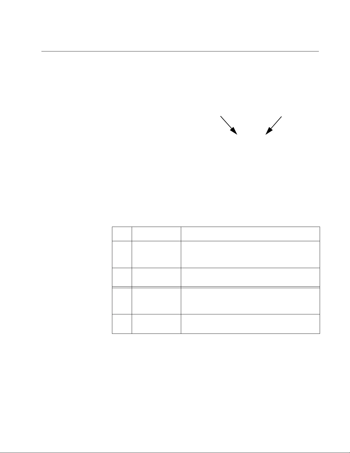
The functional description of the port Status LEDs are given in Table 1.
Table 1. LED Functions
LED Color Description
TX
Solid Green1,2
1. In Link Test mode, the TX and RX link LEDs indicate link independently of each
other based on whether their respective port has a compatible link.
Indicates a link is established on the copper
port.
OFF Indicates that a link is not established on the
copper port.
FX
Solid Green1,2
2. In Missing Link mode, the TX and FX LEDs will not indicate a link (OF F) until
both ports are simultaneously linked successfully (Solid Green).
Indicates a link is established on the fiber port.
OFF Indicates that a link is not established on the
fiber port.

Chapter 1: Product Overview
18
Auto MDI/MDIX
An RJ-45 twisted-pair port on an 100 Mbps Ethernet network device can
have one of two possible wiring configurations: MDI or MDI-X. The RJ-45
port on a PC, router, or bridge is typically wired as MDI, while the twisted-
pair port on a switch or hub is usually MDI-X.
The AT-MC102XLPCI Media Converter features automatic MDI/MDI-X.
The 100Base-TX port automatically determines the configuration of the
port on the device to which it is connected and then configures itself
appropriately. For example, if a port on a media converter is connected to
a PC, which is typically wired as MDI, the port on the media converter
automatically configures itself as MDI-X. This feature allows you to use a
straight-through cable when connecting to any type of device.

AT-MC102XLPCI & AT-MC102XL P CIE 100M bps Media Co nve r ter Instal lati on Guide
19
Auto-Negotiation
The Auto-Negotiation feature is used to automatically determine a
common duplex mode between the twisted-pair port and its link partner.
This feature is enabled at the factory and is compatible with the IEEE
802.3u specification.
The 100FX port usually operates in Full Duplex mode. The goal of the
Auto-Negotiation feature is to avoid a duplex mismatch between the
copper and fiber ports of the AT-MC102XLPCI by ensuring that the
twisted-pair port and its link partner are also configured to operate in Full
Duplex mode. In most configurations, the link partner of the twisted-pair
port is configured for Auto-Negotiation by default so the Auto-Negotiation
feature of the MC102XLPCI also needs to also be activated (factory
default configuration). If the twisted-pair link partner’s port is set to Fixed
Full Duplex mode, then the MC102XLPCI should be configured with the
Auto-Negotiation disabled. In both cases, these settings allow the twisted—
pair ports to operate in Full Duplex mode.
If the twisted-pair link partner’s port is set to Fixed Half Duplex
mode, a duplex mismatch can occur with the fiber port assuming the
fiber port is operating in Full Duplex mode. This situation can result
in significant degradation of Ethernet traffic throughpu t. To avoid this
issue, ensure that the twisted-pair link partner’s port is configured for
either Auto-Negotiation or Fixed Full Duplex when the fiber port is
operating in Full Duplex mode.
The location of the jumper (J4) is shown in Figure 3. The Auto-Negotiation
configuration and jumper pin positions for jumper J4 are given in Table 2.
Figure 3. PC Board Location of Jumper J4
Chapter 1: Product Overview
20
Although it is not marked on J4, Pin 2 is positioned between pins 1
and 3.
If you choose to remove th e jumper, Allied Telesis recommends that
you re-install the jumper on the center pin (2) only, 90 degrees from
the pins 1 and 3 so that it does not get lost.
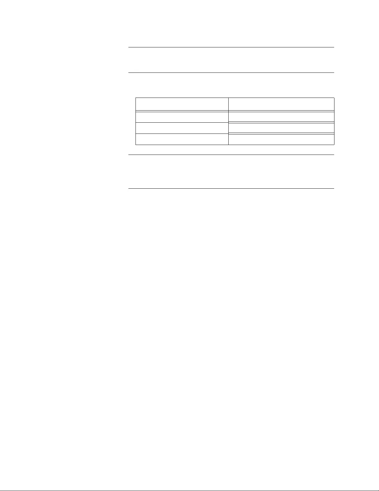
Table 2. Auto-Negotiation Configuration- Jumper J4 Positions
Pin Position of Jumper Feature Configuration
1 and 2 (Factory Default) Auto-Negotiation feature enabled
2 and 3 Auto-Negotiation feature disabled
No Jumper Installed Auto-Negotiation feature enabled

AT-MC102XLPCI & AT-MC102XL P CIE 100M bps Media Co nve r ter Instal lati on Guide
21
MissingLink & Link Test Features
The MissingLink & Link Test jumper (J5) on the PC board is configured at
the factory with the MissingLink feature enabled and Link Test disabled.
This section contains the following topics:
❒MissingLink Feature
❒Link Test Feature
❒Configuring MissingLink & Link Test Features on page 22
MissingLink
Feature The MissingLink feature enables the fiber optic and twisted-pair ports on
the media converter to pass the “Link” status of their connections to each
other. The AT-MC102XLPCI is configured for MissingLink at the factory
with pin 1 and pin 2 connected of jumper J5 (see Figure 4). When the AT-
MC102XLPCI detects that an active link has gone down on one of its
ports, it shuts down the link to its opposite port. The result is that the AT-
MC102XLPCI notifies the end node connected to the opposite port by
setting its link to go down.
This type of behavior is a form of network monitoring and fault notification
for the network device connected to the opposite port of the AT—
MC102XLPCI. Some network devices can be configured to recognize that
the loss of connection on a port and take a specific action in response to
this event. For example if the end node is a managed switch, it can be
configured to choose a redundant path as an alternative data path and/or
send out a trap to a network management station so that the network
administrator can be notified of the problem.
For example, if the t wisted-pair cable to the 100Base-TX port on the media
converter were to fail and t he link went d own, the AT-MC10 2XLPCI would
respond by dropping the link on the 100Base-FX fiber optic port. In this
way, the media converter notifies the end-node connected to th e fiber optic
port that the connectio n on the twisted-pair port has been lost. If the failure
had started with the fiber optic cabling, the unit would drop the link to the
twisted-pair port. When the failed Ethernet path is repaired and the link is
re-established, then the AT-MC102XLPCI re-establishes the link on its
opposite port.
Link Test Feature The Link Test mode provides a meth od of testing the connections between
the ports on the media converter and the nodes that are connected to the
ports. If a network problem occurs, you can perform a Link Test to
determine which port is experiencing a problem. This test allows you to
focus on the port and end-node where the problem resides.

Chapter 1: Product Overview
22
Configuring
MissingLink &
Link Test
Features
The MissingLink & Link Test jumper (J5) on the AT-MC102XLPCI
assembly is configured at the factory with the MissingLink feature enabled.
By reconfiguring this jumper, the link Test function can be enabled (and
MissingLink disabled). The location of the jumper is shown in Figure 4.
Figure 4. PC Board Location of Jumper J5
The MissingLink & Link Test configuration and jumper (J5) pin positions
are given in Table 3.
Although it is not marked on J5, Pin 2 is positioned between pins 1
and 3.
If you choose to remove th e jumper, Allied Telesis recommends that
you re-install the jumper on the center pin (2) only, 90 degrees from
the pins 1 and 3 so that it does not get lost.
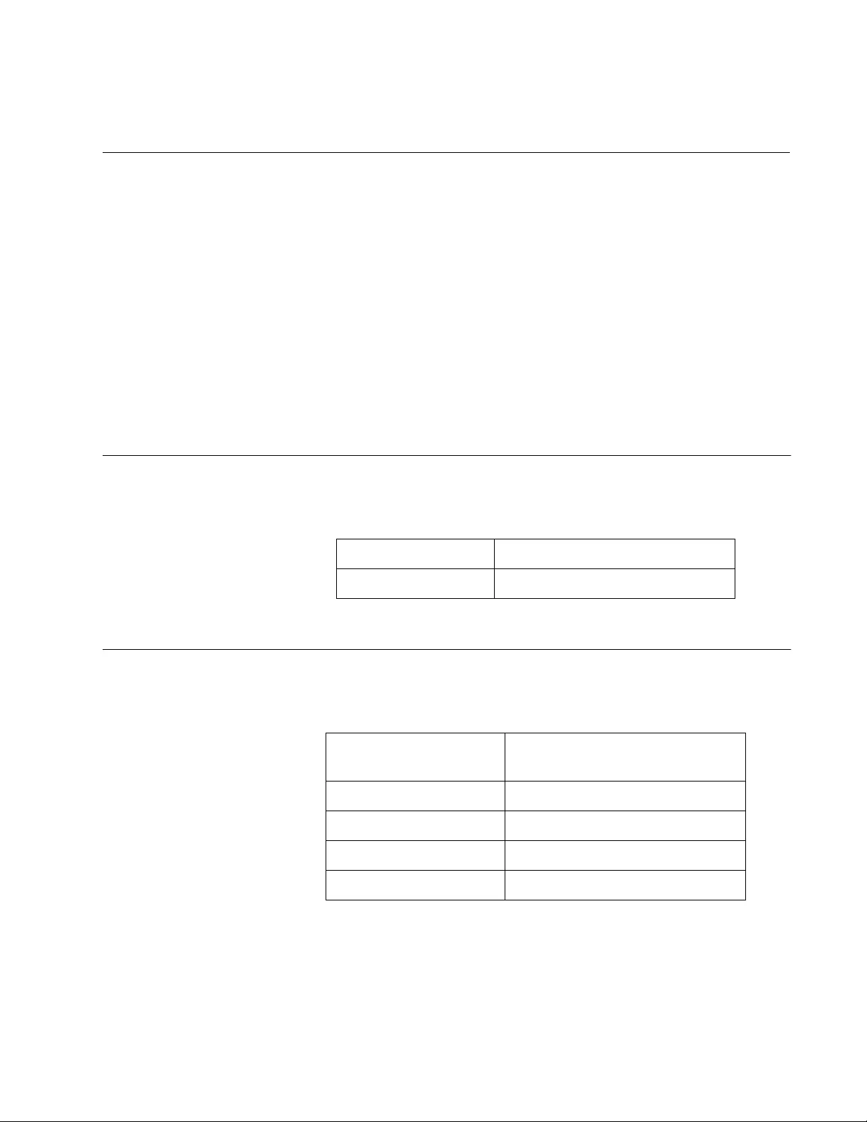
Table 3. MissingLink & Link Test — Jumper J5 Positions
Pin Position of Jumper Feature Configuration
1 and 2
(Factory Default) MissingLink function enabled
Link Test disabled
2 and 3 MissingLink function disabled
Link Test enabled
No Jumper Installed MissingLink function enabled
Link Test disabled

23
Chapter 2
Installation
This chapter contains the following installation procedures for the
AT-MC102XLPCI Media Converter.
❒«Reviewing Safety Precautions» on page 24
❒«Planning the Installation» on page 26
❒«Unpacking the Media Converter» on page 26
❒«Pre-Installation Checklist» on page 26
❒«Installing a Network Media Converter» on page 31
❒«Connecting the Network Cables» on page 34

Chapter 2: Installation
24
Reviewing Safety Precautions
Please review the following safety guidelines before installing the media
converter.
The indicates that a translation of the safety statement is
available in a PDF document titled Translated Safety Statements.
Class 1 Laser product. L1
Do not stare into the laser beam. L2
Do not look directly at the fiber optic cable ends or inspect the cable
ends with an optical lens. L6
Do not work on equipment or cables during periods of lightning
activity. E2
Operating Temperature. This product is designed for a maximum
ambient temperature of 40° degrees C. E7
All Countries: Install product in accordance with local and National
Electrical Codes. E8

AT-MC102XLPCI & AT-MC102XL P CIE 100M bps Media Co nve r ter Instal lati on Guide
25
The adapter is being installed in a system that operates with
voltages that can be lethal. Before you remove the cover of your
system, you must observe the following precautions to protect
yourself and to prevent damage to the system components:
– Remove any metallic objects or jewelry from your
hands and wrists.
– Use only insulated and nonconducting tools.
– Verify that the system is powered off an d unplugged
before accessing the internal components.
– Installation or removal of adapters must be
performed in a st atic-free environment. The use of a
properly grounded wrist strap or other person al anti-
static device and an anti-static mat is strongly
recommended. E39

Chapter 2: Installation
26
Pre-Installation Checklist
This is a pre-installation checklist f or you to follow prior to installing the AT-
MC102XLPCI media converter in your computer chassis:
❒Planning the Installation
❒Unpacking the Media Converter
❒«Replacing the Bracket» on page 28
❒«Configuring Auto-Negotiation» on page 29
❒«Configuring MissingLink & Link Test» on page 30
Planning the
Installation Observe the following guidelines when planning the installation of your
media converter:
❒The end-node connected to the fiber port of the media
converter must be configured for 100 Mbps Full
Duplex. The end-node connect ed to the copper p ort of
the media converter must be configured for either
Auto-Negotiation or 100Mbps Full duplex which is
configured with Jumper J4. See Table 2, “Auto-
Negotiation Configuration- Jumper J4 Positions” on
page 20 for more information.
❒If you choose to disable the Auto-Negotiation feature,
this must be done prior to installing the AT-
MC102XLPCI into the computer chassis. See
«Configuring Auto-Negotiation» on page 29 for more
information.
❒If you choose to disable the MissingLink feature and
enable the Link Test feature, this must be done prior to
installing the AT-MC102XLPCI into the computer
chassis. See «Configuring MissingLink & Link Test» on
page 30 and «Link Test» on page 40 for more
information.
❒Refer to Table 9, “Twisted-Pair Cable Requirements
for the 100Base-TX Ports” on page 43 for the twisted-
pair specifications.
❒Refer to Table 12, “Fiber Optic Launch Power” on page
44 for the fiber optic port specifications.
Unpacking the
Media Converter To unpack the AT-MC102XLPCI Media Converter, perform the following
procedure:

AT-MC102XLPCI & AT-MC102XL P CIE 100M bps Media Co nve r ter Instal lati on Guide
27
Wear a grounding device and observe electrostatic discharge
precautions when installing the network adapter card in a system.
Failure to observe this caution could result in damage to the card.
1. Remove all components from the shipping package.
Store the packaging material in a safe lo cation. If you need to retur n
the unit to Allied Telesis, you may re-use the packing material.
2. Make sure the following items are included in your package. If any item
is missing or damaged, contact your Allied Telesis sales.
Figure 5. AT-MC102XLPCI Media Converter Items
3. Holding the AT-MC102XLPCI by the edges, remove it from its shipping
package and place it on an anti-static surface.
4. Check the media converter for visible signs of damage, particularly on
the card’s edge connector.
One AT-MC102XLPCI
100Mbps Media Converter
with factory-installed
low profile bracket
One standard profile
PCI bracket

Chapter 2: Installation
28
Do not attempt to install a damaged AT-MC102XLPCI media
converter. If it is damaged, contact Allied Telesis.
Replacing the
Bracket The AT-MC102XLPCI Media Converter is shipped with the low-profile
bracket attached to the adapter and a separate standard-profile bracket.
You may need to replace the low-profile bracket attached to your adapter
with the standard profile bracket depending on your PC.
The following procedure describes how to remove the low-profile bracket
from the adapter and replace it with the standard bracket. You can also
use this procedure to remove the standard bracket and replace it with the
low-profile bracket.
To replace the low-profile bracket with the standard bracket, perform the
following procedure:
1. Remove the screws that attach the low-profile bracket to the adapter.
See Figure 6.
Figure 6. Removing the Low-Profile Bracket

AT-MC102XLPCI & AT-MC102XL P CIE 100M bps Media Co nve r ter Instal lati on Guide
29
2. Align the tabs of the standard bracket with the holes on the adapter
and fasten the screws onto the adapter. See Figure 7.
Figure 7. Installing the Standard Bracket
Configuring
Auto-Negotiation A jumper (J4) is pre-installed at the factory between pins 1 and 2 which
enables the Auto-Negotiation feature. Re fer to Figure 4 for the location o f
this jumper.
If you choose to move this jumper to reconfigure the Auto-Negotiation
feature, it must be done prior to the installation of the AT-MC102XLPCI
assembly into your computer chassis. Refer to Table 2 on page 20 for a
functional description if this jumper (J4). To disable Auto-Negotiation,
install jumper J4 between pins 2 and 3.
If this jumper (J4) is removed from the assembly, the Auto-
Negotiation function is enabled.
If you choose to remove the jumper, Allied Telesis recommends that
you re-install the jumper on the center pin (2) only, 90 degrees from
the pins 1 and 3 so that it does not get lost.

Chapter 2: Installation
30
Configuring
MissingLink &
Link Test
The MissingLink feature is enabled by default from the factory with a
jumper (J5) pre-installed between pins 1 and 2 on the AT-MC102XLPCI
assembly. Refer to Figure 4 for the location of this jumper.
If you choose to disable MissingLink and enable Link Test, it must be done
prior to the installation of the AT-MC102XLPCI assembly into your
computer chassis. Refer to Table 3 on page 22 for a functional description
of this jumper (J5). To disable MissingLink and enable Link Test, install
jumper J5 between pins 2 and 3.
If this jumper (J5) is removed from the assembly, the MissingLink
feature is enabled and Link Test is Disabled.
If you choose to remove th e jumper, Allied Telesis recommends that
you re-install the jumper on the center pin (2) only, 90 degrees from
the pins 1 and 3 so that it does not get lost.

AT-MC102XLPCI & AT-MC102XL P CIE 100M bps Media Co nve r ter Instal lati on Guide
31
Installing a Network Media Converter
The following instructions apply to installing AT-MC102XLPCI Media
Converter in most systems. For details about performing these tasks on
your particular system, refer to the manuals that were supplied with your
computer system.
To perform this procedure, you need to provide a Phillips-head
screw driver.
To install an AT-MC102XLPCI Media Converter perform the following
procedure:
1. Read the «Reviewing Safety Precautions» on page 24 and follow the
«Pre-Installation Checklist» on page 26 before proceeding to the next
step.
2. If your computer is powered on, turn off the power.
3. When the system is completely shut down, unplug your computer.
4. Ensure that proper electrical grounding procedures have been
followed.
High voltage inside the system presents a sa fety hazard. Make sure
the power is off before removing the cover.
5. Remove the system cover. See Figure 8 .
Figure 8. Removing the PC Cover

Chapter 2: Installation
32
6. Depending on which product you are in stalling , se lect and empty non-
shared PCI or PCIe slot on the computer motherboard.
7. Remove the faceplate that is associated with the card slot you have
identified for installation. See Figure 9.
Figure 9. Removing the Faceplate From PCI Slot
Keep the faceplate in a safe place. You may need it for future use.
8. On the inside of the computer chassis, push the media converter card
until it is firmly seated in the appropriate PCI slot by applying even
pressure at both corners of the card. See Figure 10. Make sure the
card is securely seated.
Figure 10. Inserting the Adapter with a High-profile Bracket

AT-MC102XLPCI & AT-MC102XL P CIE 100M bps Media Co nve r ter Instal lati on Guide
33
Do not use excessive force when s eating the card, because this may
damage the system or the adapter. If the card resists seating,
remove it from the system, realign it, and try again.
9. Secure the network adapter card to the chassis with a Phillips-head
screw (not provided). See Figure 11.
Figure 11. Securing the Adapter with a High-profile Bracket
10. Replace the system’s cover and secure it with the screws removed in
Step 5.
11. Power the system on.
Once power is turned on to the computer system and it returns to
proper operation, the AT-MC102XLPCI Media Converter is fully
installed. Next, connect the network cables. See «Connecting the
Network Cables» on page 34.

Chapter 2: Installation
34
Connecting the Network Cables
The AT-MC102XLPCI Media Converter has an SC type fiber optic
connector with a transmit and receive ports and one twisted-pair
connector.
For the fiber optic cable specifications, see Appendix A, “Fiber Optic Port
Specifications” on page 43.
For twisted-pair cable specifications and pin-out information, see
Appendix A, “RJ-45 Twisted-Pair Port Specifications” on page 43.
To connect a network cable to the adapter, perform the following
procedure:
The fiber optic ports contain a Class 1 LED device. When the ports
are disconnected, always cover them with the provided plug.
Exposed ports may cause skin or eye damage.
1. On the AT-MC102XLPCI Media Converter, connect the fiber optic
cable to the Ethernet fiber optic port. See Figure 12.
Figure 12. Connecting the Fiber Optic Cable to the AT-MC102XLPCI
Media Converter
2. Connect the opposite end of the fiber optic cable to the link partner of
the AT-MC102XLPCI Media Converter.
The TX port of the AT-MC1 02XLPCI should be connected to the RX
port of the link partner. Similarly, the RX port of the
AT-MC102XLPCI should be connected to the TX port of the link
partner.

AT-MC102XLPCI & AT-MC102XL P CIE 100M bps Media Co nve r ter Instal lati on Guide
35
3. On the AT-MC102XLPCI Media Converter, connect the twisted-pair
Ethernet cable to the RJ-45 port. See Figure 13.
Figure 13. Connecting the Twisted-pair Cable to the AT-MC102XLPCI
Media Converter
4. Connect the other end of the twisted-pair cable to the link partner of
the AT-MC102XLPCI Media Converter.
After you conn ect the system to the network and power is supplied, the
AT-MC102XLPCI Media Converter attempts to establish a link at 100
Mbps.
After the cables are properly connected at both ends and power is
supplied to the devices at both ends of each cable, the media
converter port LEDs should be functional. See «Status LEDs» on
page 17 for a description of LED operation.

Chapter 2: Installation
36

37
Chapter 3
Troubleshooting
The following guidelines are provided to test and troubleshoot the
installation in the event a problem occurs:
❒Twisted-Pair LED
❒Fiber Port LED on page 39
❒Link Test on page 40

Overview
38
Twisted-Pair LED
If the LINK LED for the twisted-pair port is OFF, do the following:
1. Verify that the PC is powered ON and has booted up successfully.
2. Check that the end-node connected to the port is powered ON and is
operating properly.
3. Check that the twisted-pair cable is securely connected to the twisted-
pair port on the media converter and on the remote end-node.
4. Make sure that the twisted-pair cable does not exceed 100 meters
(328 feet) and that you are using Category 5 or better Ethernet cable.
5. Verify that the copper port of the media converter and the copper end
node are configured with matching speed/duplex settings (both set to
Auto Negotiate OR both set to 100Mbps Full Duplex).
6. If you are still experiencing problems, refer to Contacting Allied Telesis
on page 13 or visit our web site at www.alliedtelesis.com/support.

AT-MC102XLPCI & AT-MC102XL P CIE 100M bps Media Co nve r ter Instal lati on Guide
39
Fiber Port LED
If the LINK LED for the fiber optic port is OFF, do the following:
1. Verify that the PC is powered ON and has booted up successfully.
2. Verify that the end-node connected to the port is powered ON and is
operating properly.
3. Check that the fiber optic cable is securely connected to the fiber optic
port on the media converter and on the end-node.
4. Verify that the end node connected to the fiber port of the media
converter is a 100FX port and that it is configured for 100 Mbps Full
Duplex.
5. Make sure that the cable connected to the media converter’s receiver
port (RX) is connected to the end-node’s transmitter port (TX) and that
the media converter’s transmitter port (TX) is connected to the end-
node’s receiver port (RX).
6. Test the attenuation on the fiber optic cable to ensure that it does not
exceed acceptable values. Refer to Fiber Optic Port Specifications on
page 43 for more information.
7. Verify that you are using the appropriate type of fiber optic cable and
that you have not exceeded the maximum operating distance. For
maximum operating distances and cable types, refer to Fiber Optic
Port Specifications on page 43.
8. Check that the operating specifications (e.g., wavelength and
maximum operating distance) of the fiber optic port on the end-node
are compatible with the operating specifications of the fiber optic port
on the media converter. Refer to Fiber Optic Port Specifications on
page 43 for more information.
9. If you are still experiencing problems, refer to Contacting Allied Telesis
on page 13 or visit our web site at www.alliedtelesis.com/support.

Overview
40
Link Test
To check hardware reliability of the media converter, perform the following
procedure:
1. If the media converter is not already configured for Link Test mode,
Power OFF the PC chassis where t he media converter is installed and
remove the the media converter from the chassis.
2. Configure the media converter for Link Test and re-install the media
converter in the PC and then re-install the media converter in the PC
chassis.
See Installing a Network Media Converter on page 31 for more
information.
See Configuring MissingLink & Link Test on page 30 for more
information.
3. Connect the RJ-45 twisted pair port to a 100Base port on an end-
node, such as an Ethernet switch, and power ON the end-node.
4. Verify that the copper port of the media converter and the copper end
node are configured with matching speed/duplex settings (both set to
Auto Negotiate OR both set to 100Mbps Full Duplex).
5. Using a tested and good fiber patch cable, attach the fiber cable to the
fiber connector of the media converter and the opposite end to a
another Ethernet device with a compatible 100 MB fiber port. Power
ON the end-node.
6. Power ON the PC chassis where the media converter is installed.
7. Verify that the PC is powered ON and has booted up successfully.
8. Verify that the LINK LED on both the twisted pair and fiber optic ports
are green.
9. If the LEDs are green, the unit is working properly and there is a
problem elsewhere on the segment.
10. If the LEDs are OFF, , refer to Conta cting Allie d Te lesis on page 13 or
visit our web site at www.alliedtelesis.com/support.
41
Appendix A
Technical Specifications
This appendix contains the following specifications
❒Physical Specifications
❒Operating and Storage Conditions
❒Electrical Rating on page 42
❒Agency Certifications on page 42
❒Environmental Compliance on page 42
❒RJ-45 Twisted-Pair Port Specifications on page 43
❒Fiber Optic Port Specifications on page 43
Physical Specifications
Operating and Storage Conditions
Table 4. Physical Specifications
Dimensions (W x H) 12.5 cm x 6.4 cm (4.9 in x 2.5 in)
Weight .062 kg (2.2 oz)
Table 5. Operating and Storage Conditions
Operating
Temperature 0° C to 40° C (32° F to 105° F)
Storage Temperature -20° C to 80° C (-4° F to 176° F)
Operating Humidity 5% to 90% non-condensing
Storage Humidity 5% to 95% non-condensing
Operating Altitude Up to 3,048 meters (10, 000 feet)
Chapter : Technical Specifications
42
Electrical Rating
Agency Certifications
Environmental Compliance
Table 6. Electrical Rating
Input Supply Voltage 3.3 V DC
Power Consumption 1.65 Watts Maximum
Table 7. Agency Certifications
RFI Emissions FCC Part 15 Class B, EN55022 Class B,
CISPR 22 Class B, C-TICK
Immunity EN55024
Electrical Safety UL 60950-1 (CULUS), EN60950-1 (TUV), CE
Laser Safety: EN60825-1
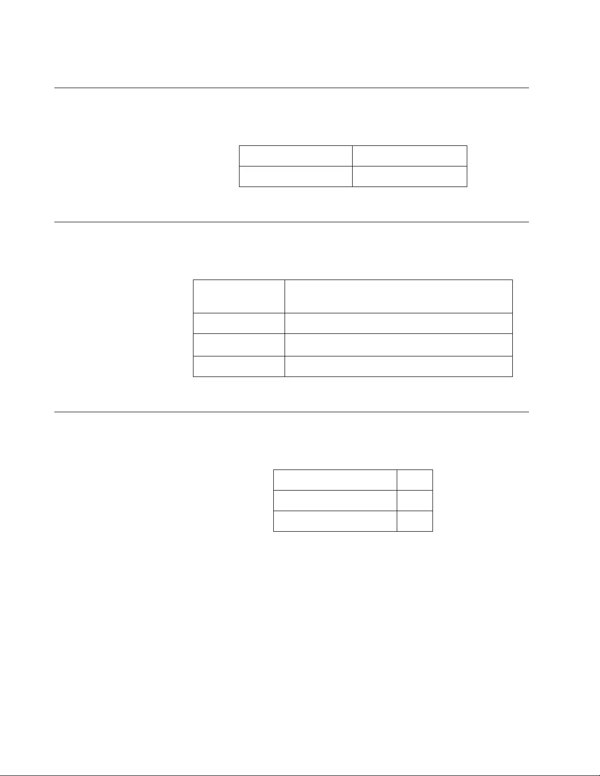
Table 8. Environmental Compliance
Eu-RoHS compliant Yes
China-RoHS compliant Yes
WEEE Yes
AT-MC102XLPCI & AT-MC102XL P CIE 100M bps Media Co nve r ter Instal lati on Guide
43
RJ-45 Twisted-Pair Port Specifications
This section contains the following RJ-45 twisted pair port specifications:
❒Cable Requirements on page 43
❒RJ-45 Twisted- Pair Port Pinouts on page 43
Cable
Requirements The cable requirements of the RJ-45 twisted-pair port are given in Table 9.
RJ-45 Twisted-
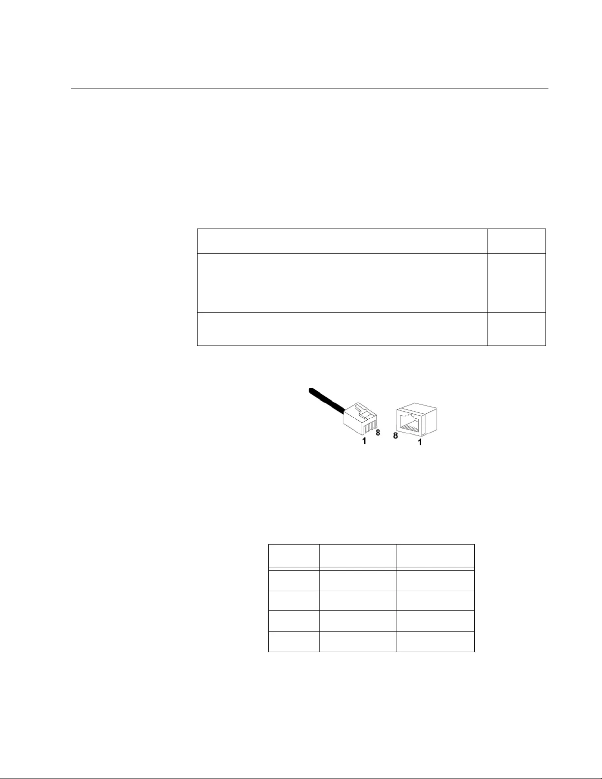
Pair Port Pinouts Figure 14 illustrates the pin layout to an RJ-45 connector and port.
Figure 14. RJ-45 Connector and Port Pin Layout
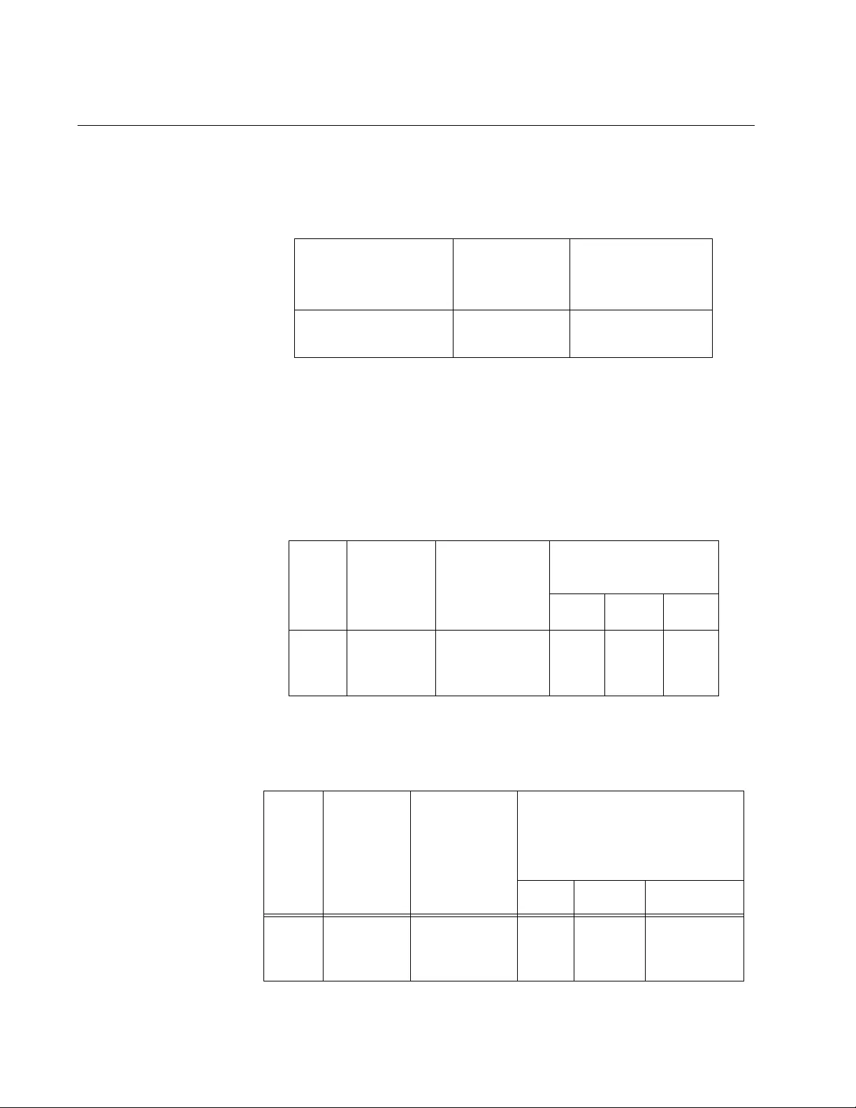
Table 10 lists the MDI and MDI-X RJ-45 pin signals with a twisted-pair
port.
Table 9. Twisted-Pair Cable Requirements for the 100Base-TX Ports
Cable Type 100Mbps
Standard TIA/EIA 568-A-compliant Category 5 or TIA/EIA
568-B-compliant Enhanced Category 5 (Cat 5e) shielded
or unshielded cabling with 100 ohm impedance and a
frequency of 100 MHz.
Yes
Standard TIA/EIA 568-B-compliant Category 6 or 6a
shielded cabling. Yes
Table 10. RJ-45 Pin Signals for MDI and MDI-X
Pin MDI Signal MDI-X Signal
1TX+ RX+
2TX— RX—
3RX+ TX+
6RX— TX—
Chapter : Technical Specifications
44
Fiber Optic Port Specifications
The cable requirements of the fiber port are given in Table 11.
The fiber optic specifications are given in the following tables:
❒Table 12, “Fiber Optic Launch Power”
❒Table 13, “Fiber Optic Receive Power”
❒Table 14, “Fiber Optic Cable Distance” on page 45
❒Table 15, “Fiber Optic Loss Specifications” on page 45
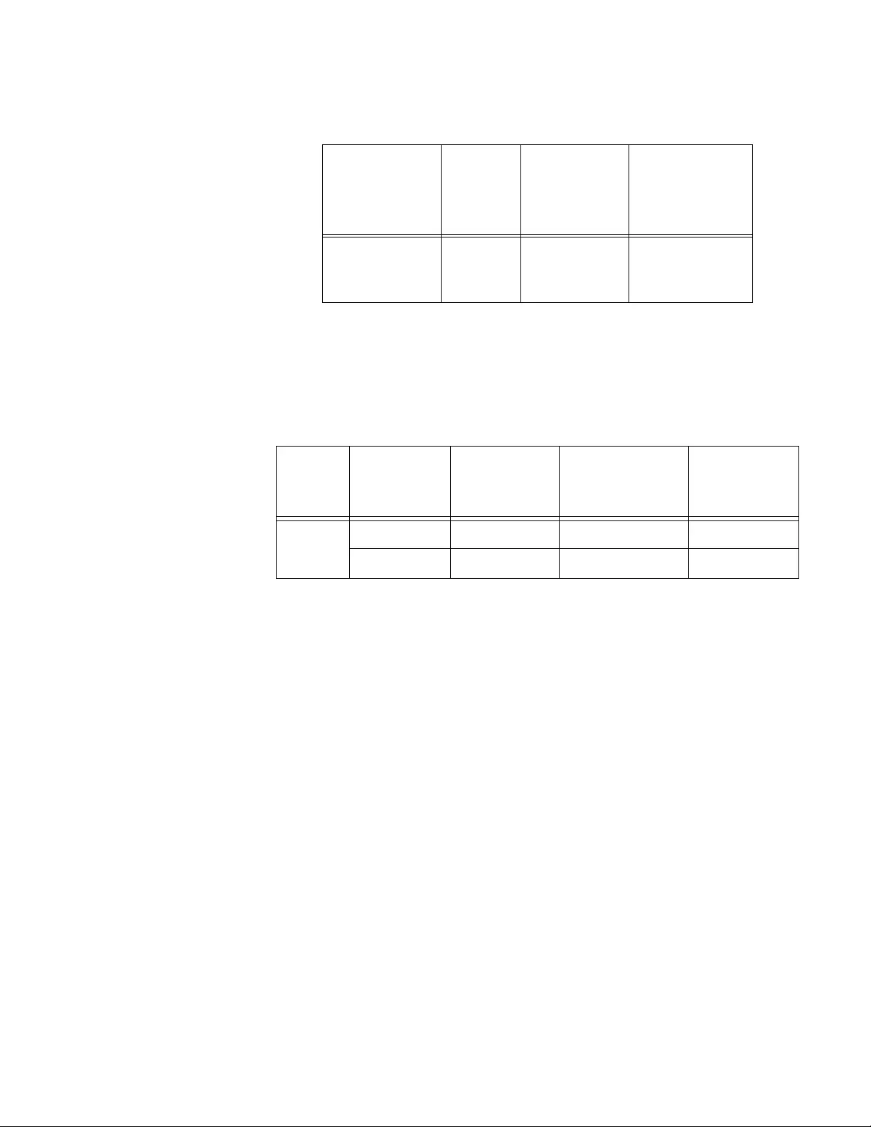
Table 11. Fiber Optic Cable Loss Budget
Type of Fiber Optic
Cable
Maximum
Operating
Distance
Maximum
Allowable Loss
Budget
50/125 or 62.5/125
micron multimode 2 km (1.2 mi) 13 dB at 1310 nm
Table 12. Fiber Optic Launch Power
Fiber
Type
1
1. MMF = Multimode Fiber
Fiber
Optic
Diameter
(microns)
Optical
Wavelength
Launch Power
(dBm)2
2. The launch power is measured at one meter from the transmitter.
Min. Avg. Max.
MMF 50/125
or
62.5/125 1310 nm -19.0 -16.8 -14.0
Table 13. Fiber Optic Receive Power
Fiber
Type
1
1. MMF = Multimode Fiber / SMF = Single-mode Fib er
Fiber
Optic
Diameter
(microns)
Optical
Wavelength Receive Power (dBm)
Min. Typical Saturation
MMF 50/125
or
62.5/125 1310 nm -31.8 -34.5 -14.0
AT-MC102XLPCI & AT-MC102XL P CIE 100M bps Media Co nve r ter Instal lati on Guide
45
Table 14. Fiber Optic Cable Distance
Fiber Type1
1. MMF = Multimode Fiber / SMF = Single-mode Fiber
Max.
Power /
Link
Budget
Min.
Distance
Spec.2
2. The recommended minimum range is stated in all cases where
the maximum transmitter output power exce eds the receivers
saturation level. This is to prevent blinding or burning out of the
optical receiver on the far-end-node.
Max. Distance
Spec.
50/125 MMF
or
62.5/125 MMF 12.8 dB 0 2 km (1.2 mi)
Table 15. Fiber Optic Loss Specifications
Fiber
Type1
1. MMF = Multimode Fiber
Fiber Optic
Diameter
(microns)
Optical
Wavelength Typical Loss
Factor (dB/km) Bandwidth
(Mhz * km)
MMF 50/125 1310 nm 1.00 400
62.5/125 1310 nm 1.00 500

Chapter : Technical Specifications
46