

DIGITAL RECORDER
INSTALLERʼS MANUAL
MODEL
DX-TL4516U
THIS INSTRUCTION MANUAL IS IMPORTANT TO YOU. PLEASE READ IT BEFORE USING YOUR DIGITAL RECORDER.
1
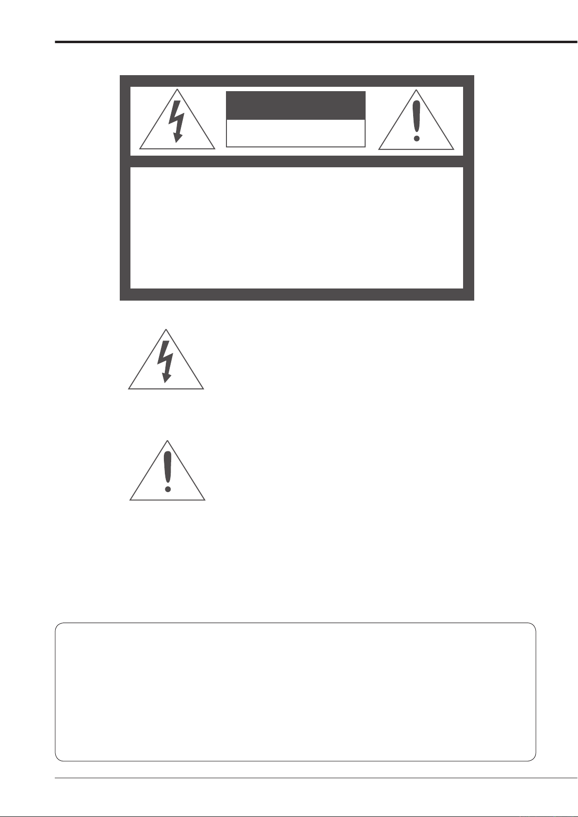
WARNING
RISK OF ELECTRIC SHOCK
DO NOT OPEN
WARNING:
REFER SERVICING TO QUALIFIED SERVICE PERSONNEL.
TO REDUCE THE RISK OF ELECTRIC SHOCK,
DO NOT REMOVE COVER (OR BACK)
NO USER-SERVICEABLE PARTS INSIDE
The lightning flash with arrowhead symbol, within
an equilateral triangle, is intended to alert the user
to the presence of uninsulated “dangerous voltage”
within the product’
sufficient magnitude to constitute a risk of electric
shock.
The exclamation point within an equilateral triangle
is intended to alert the user to the presence of
important operating and maintenance (servicing)
instructions in the literature accompanying the
appliance.
s enclosure that may be of
WARNING:
TO PREVENT FIRE OR SHOCK HAZARD, DO NOT EXPOSE THIS APPLIANCE TO RAIN OR
MOISTURE.
CAUTION:
TO PREVENT ELECTRIC SHOCK DO NOT USE THIS (POLARIZED) PLUG WITH AN
EXTENSION CORD, RECEPTACLE OR OTHER OUTLET UNLESS THE BLADES CAN BE
FULLY INSERTED TO PREVENT BLADE EXPOSURE.
i
AVERTISSEMENT
DANGER D’ÉLECTROCUTION
NE PAS OUVRIR
AVERTISSEMENT:
CUTION, NE PAS OUVRIR LE COUVERCLE
(OU LA PARTIE ARRIÈRE). AUCUNE PIECE
RÉPARABLE PAR L’UTILISATEUR NE SE
TROUVE À L’INTÉRIEUR.
POUR TOUTE INTERVENTION D’ENTRETIEN
OU DE RÉPARATION SE CONFIER AUX TECH NICIENS QUALIFIÉS.
La flèche symbolisant l’éclair dans un triangle équilateral
a pour objet de tirer l’attention de l’utilisateur sur le fait, qu’
il y a des “tensions dangereuses” non-isolées à l’intérieur
de l’enceinte du produit qui peuvent être suffi
importantes pour conduire au risque d’électrocution.
POUR ÉLIMINER TOUT RISQUE D’ÉLECTRO-
samment
Le point d’exclamation au sein d’un triangle équilateral a
pour objet de tirer l’attention de l’utilisateur sur le fait qu’
il y a des instructions de mise en service et d’entretien (de
réparation) dans les fi
doivent obligatoirement être respectées.
ches descriptives de l’appareil qui
AVERTISSEMENT:
AFIN D’ÉVITER TOUT RISQUE D’INCENDIE OU D’ÉLECTROCUTION, NE PAS EXPOSER CET
APPAREIL À LA PLUIE NI À L’HUMIDITÉ.
ATTENTION:
POUR PRÉVENIR LES CHOCS ÉLECTRIQUES NE PAS UTILISER CETTE FICHE POLARISÉE
AVEC UN PROLONGATEUR, UNE PRISE DE COURANT OU UNE AUTRE SORTIE DE
COURANT, SAUF SI LES LAMES PEUVENT ÊTRE INSÉRÉES À FOND SANS EN LAISSER
AUCUNE PARTIE À DÉCOUVERT.
Beginning
ii

Important safeguards
PLEASE READ ALL THESE INSTRUCTIONS REGARDING YOUR RECORDER AND RETAIN FOR FUTURE REFERENCE. FOLLOW ALL WARNINGS AND INSTRUCTIONS MARKED ON THE RECORDER.
Ventilation
1. Read Instructions
All the safety and operating instructions should be
read before the appliance is operated.
Retain Instructions
2.
The safety and operating instructions should be
retained for future reference.
Heed Warnings
3.
All warnings on the appliance and in the operating
instructions should be adhered to.
9.
Slots and openings in the cabinet are provided for
ventilation and to ensure reliable operation of the
product and to protect it from overheating, and
these openings must not be blocked or covered.
This product should never be placed near or over
a radiator or heat register. This product should
not be placed in a built-in installation such as
a bookcase or rack unless proper ventilation is
provided or the manufacturer’s instructions have
been adhered to.
Follow Instructions
4.
All operating and use instructions should be
followed.
Cleaning
5.
Unplug this product from the wall outlet before
cleaning. Do not use liquid or aerosol cleaners.
Use a damp cloth for cleaning.
Attachments
6.
Do not use attachments not recommended by
the product manufacturer as they may cause
hazards.
Water and Moisture
7.
Do not use this product near water – for example,
near a bath tub, wash bowl, kitchen sink, or
lau nd ry tub, i n a wet b as eme nt , or ne ar a
swimming pool, and the like.
Accessories
8.
Do not place the product on an unstable cart,
stand, tripod, bracket, or table. The product
may fall, causing serious injury. Any mounting of
the appliance should follow the manufacturer’s
instructions, and should use a mounting accessory
recommended by the manufacturer.
An appliance and cart combination should be
moved with care. Quick stops, excessive force,
and uneven surfaces may cause the appliance
and cart combination to overturn.
10. Power Sources
T
his product should be operated only from the
type of power source indicated on the marking
label. For products intended to operate from
battery power, other sources, refer to the operating
instructions.
1. Grounding or Polarization
1
This product is equipped with a 3-wire groundingtype plug, a plug having a third (grounding) pin.
This plug will only fit into a grounding-type power
outlet. This is a safety feature. If you are unable
to insert the plug into the outlet, contact your
electrician to replace your obsolete outlet. Do not
defeat the safety purpose of the grounding-type
plug.
Power-Cord Protection
12.
Power-supply cords should be routed so that
they are not likely to be walked on or pinched
by items placed upon or against them, paying
particular attention to cord at plugs, convenience
receptacles, and the point where they exit from
the appliance.
Lightning
13.
For added protection for this product receiver
dur in g a lig ht ni ng st or m, or w he n i t is le ft
unattended and unused for long periods of time,
unplug it from the wall outlet. This will prevent
damage to the product due to lightning and powerline surges.
iii
Overloading
14.
Do not overload wall outlets and extension cords
as this can result in a risk of fire or electric shock.
15. Object and Liquid Entry
Never spill liquid of any kind on the product.

16. Servicing
Do not attempt to service this product yourself as
opening or removing covers may expose you to
dangerous voltage or other hazards. Refer all
servicing to qualified service personnel.
17. Damage requiring Service
Unplug this product from the wall outlet and refer
servicing to qualified service personnel under the
following conditions:
Whe n th e po wer -s up pl y c or d or plug i s
(a)
damaged.
If liquid has been spilled, or objects have fallen
(b)
into the product.
If the product has been exposed to rain or
(c)
water.
(d) If the product does not operate normally by
following the operating instructions. Adjust
onl y th ose co ntr ols th at are co ver ed by
the operating instructions as an improper
adjustment of other controls may result in
damage and will often require extensive work
by a qualified technician to restore the product
to its normal operation.
If the product has been dropped or the cabinet
(e)
has been damaged.
When the product exhibits a distinct change in
(f)
performance, this indicates a need for service.
Replacement Parts
18.
When replacement parts are required, be sure the
service technician has used replacement parts
specified by the manufacturer or have the same
characteristics as the original part. Unauthorized
substitutions may result in fire, electric shock or
other hazards.
19.
Safety Check
Upon completion of any service or repairs to this
product, ask the service technician to perform
safety checks to determine that the product is in
safe operating conditions.
Heat
20.
The product should be situated away from heat
sources such as radiators, heat registers, stoves,
or other products (including amplifiers) that
product heat.
This equipment does not provide connection
21.
for used with outdoor or cable distribution
systems.
NOTE
This equipment has been tested and found to comply with the limits for a Class A digital device, pursuant to Part 15 of the FCC Rules. These limits are designed to provide reasonable
protection against harmful interference when the equipment is operated in a commercial environment. This equipment generates, uses, and can radiate radio frequency energy and, if
not installed and used in accordance with the instruction manual, may cause harmful interference to radio communications. Operation of this equipment in a residential area is likely to
cause harmful interference in which case the user will be required to correct the interference at
his own expense. Changes or modifications not expressly approved by the party responsible
for compliance could void the user’s authority to operate the equipment.
NOTE
THIS CLASS A DIGITAL APPARATUS COMPLIES WITH CANADIAN ICES-003.
CET APPAREIL NUMÉRIQUE DE LA CLASSE A EST CONFORME À LA NORME NMB-003 DU CANADA.
Beginning
iv

Caution and care
HEAVY OBJECTS SHOULD NEVER BE PLACED ON THE UNIT (E.G., MONITOR)
NEVER REMOVE THE TOP COVER AND TOUCH OR INSERT ANY OBJECT INSIDE THE UNIT
Touching the inside of the cabinet or inserting foreign objects of any kind through the disc loading slot or ventilation holes not
only creates a safety hazard but can also cause extensive damage.
PROTECT THE POWER CORD
Damage
carefully replace it with a new power cord.
Do
unit OFF and disconnect power from the unit. Confirm that more than one minute have passed since the power cord and the
connecting cords were disconnected, then move this unit. Make sure to take the disc out and close the disc loading slot.
UNPLUG THE POWER CORD DURING
Turn off the power and unplug the power cord during a long absence.
MAINTAIN GOOD VENTILATION
Do not obstruct the many ventilation holes on the unit. For maximum ventilation, leave some space around the unit and place
the unit on a hard level surface only, and ensure it is not covered during use. Heavy objects should never be placed on the
unit.
WHEN NOT IN USE
When not in use, always eject the disc and turn OFF the MAIN switch.
CABINET CARE
Never use petroleum-based cleaners. Clean with a soft cloth moistened with soap and water and wipe dry.
PVC cables or leads should not be left in contact with the cabinet surface for long periods.
INST
For excellent performance and lasting reliability install in a location that is:-
1.
2. A solid vibration-free surface.
3. Free from high humidity, excessive dust and away from magnetic fields.
4. Please ensure that the ventilation fan located on the unit’s back panel is not blocked.
UNSUITABLE LOCATIONS
Placing the unit in the following places might shorten the product life:
•
• Places where excessive hydrogen sulfide is likely to be generated, such as hot-springs areas
• Places or locations with salt air environment.
NO OBJECTS FILLED WITH LIQUIDS, SUCH AS VASES, SHALL BE PLACED ON THE APPARATUS.
DO NOT PLACE HEAVY OBJECT ON THIS UNIT.
DO NOT STEP ONTO THIS UNIT.
DO NOT PLACE ANY OBJECTS IN FRONT OF THE DISC LOADING SLOT.
The unit may drop or fall by losing its balance. It may cause injury or failure of the unit.
W
to the power cord may cause fire or electrical shock. If the power cord is damaged, turn OFF the MAIN switch and
not move this product with the power-on as the built-in HDD may be damaged. If you need to move the product, turn the
A LONG ABSENCE
ALLATION LOCATION
Well ventilated, out of direct sunlight and away from direct heat.
Extremely cold places, such as refrigerated warehouses and ice houses
ARNING: TO PREVENT FIRE OR SHOCK HAZARD, DO NOT EXPOSE THIS APPARATUS TO RAIN OR MOISTURE.
THIS APPARATUS MUST BE GROUNDED.

WARNING:
The supplied power cord is used for 120 V only. Never connect to any outlet or power supply having a different
voltage or frequency.
Notice about construction of the surveillance system using this unit
• This unit can be controlled by the external devices via RS-232C terminal or LAN terminal. This unit can also be used to
control external devices via external terminal, RS-422/485 terminal, or RS-232C terminal. Owning to these functions,
this unit flexibly applies to the high grade security system, but the whole surveillance system may be affected by the
malfunction of this unit or the external devices depending on the setting contents of this unit, the connection with the
external devices, or combination between this unit and the external devices.
When configuring a surveillance system using this unit, it is recommended to confirm first that this unit operates normally
•
with the other devices connected.
It is recommended to copy or back up the important recorded contents.
•
• Damages rising out of any operational error of the surveillance system or loss of the recorded data or any other
damages because of any user malfunction of this unit are not covered.
Do not use the notification function of this unit for making critical judgement nor any purpose related to human lives.
•
• When this unit cannot recognize the external device which is being used for recording due to the power failure,
decreased voltage, or other failures, the recording point may be moved to the internal HDD of this unit or the other
external HDD. To prevent occurence of such problem, it is recommended to use uninterruptible power supply.
• If the power plug is disconnected or the breaker switch is turned off during recording, HDD may be damaged or playback
of recorded data may become impossible.
If the breaker switch is turned on and off everyday, set the timer recording to be performed only for the period that the
breaker is on and do not turn off the breaker during recording.
There may be cases when the unit’s built-in motion detection function does not operate properly due to external condition,
video input signal, or other factors
.
The user will not be indemnified for problems (e.g., recording failure or playback failure) that occur with either the unit or a
connected device during operation. It is recommended to back up the important recordings regularly as a precaution against
possible breakdowns and accidents
Recordable time and product warranty
Continuous
operation of this unit. They indicate the period neither for product warranty nor that for reliability of used parts.
• This unit uses a built-in HDD, which is a precision device. Handle this unit with sufficient care.
• Do not subject this unit to vibrations or shocks. This may cause trouble specially when the power of the unit is turned on
or when the HDD is being accessed, and suffi
• Do not disconnect the power plug while the power of the unit is turned on or while recording or playing.
• For early detection of faults, we recommend that you request inspection once a year.
The
replaced every 30,000 hours.
(This interval is for reference purpose only and does not indicate the warranty period of the parts.)
DISCLAIMER
In any event, Mitsubishi assumes no responsibility or reliability for the following:
Disassembly, repair, or alteration of this unit by user or installer.
1.
2. Failure or breakdown in or damage to this unit resulting from misuse or careless handling by user or installer.
3. Inconvenience or damages arising out of inability to display or record pictures due to any reason or cause other than
breakdown or failure in this unit.
Failure in this unit due to combination with other equipment manufactured by a third party or inconvenience or damages
4.
resulting from such failure.
Inconvenience, damages, or claims arising out of breakdown in this unit or loss of recorded video data due to
5.
replacement of the built-in HDD by user or installer.
6. Inconvenience or damages arising out of breakdown in this unit or inability to display or record pictures due to natural
disaster including earthquake and storm.
Inconvenience, damages, or claims arising out of breakdown in this unit or loss of recorded video data due to impact or
7.
vibration to the built-in HDD or an environmental factor such as temperature at the installation site.
Demand for damages or other claim of infringement of privacy if the pictures monitored or recorded by user become
8.
public or are used for any purpose other than surveillance for whatever reason.
recordable time and the estimated time displayed on the menu screen indicate the continuous time of recording
HDD and cooling fan of this unit are driving parts. For stable recording, it is recommended that both of these parts are
.
cient care is required.
CLASS 1 LASER PRODUCT
Beginning
3

Caution and care (continued)
INSTALLATION LOCATION AND HANDLING
• Place this unit horizontally and in a stable place. If this unit is not placed correctly and used in an unstable place, the unit
may be damaged such as removal of the DVD/CD disc.
Do not place this unit close to other electronic or magnetic equipment. This will avoid video and audio distortion.
•
• When a monitor and this unit are placed vertically, the pictures may be distorted or DVD/CD disc may not be ejected.
• Do not let stick your hands into the disc loading slot. You may get your hand caught in the slot and may got injured. If you
get your hand caught, do not get out of the slot by force. Contact your dealer after turning off the power and disconnecting
the plug.
DVD/CD DISC
Do not use the disc cracked, deformed or repaired with adhesive. The disc may fly into pieces and cause injury.
•
• Do not touch the playback surface when holding the disc.
• When dew condensation occurs on the disc, wipe the surface off before use.
• Dirt such as fingerprints or dust causes the deterioration of the picture quality and audio quality. Gently wipe the DVD/CD
disc from the center to the outside with a soft cloth.
When the disc is very dirty, soak a soft cloth with water and screw water of it, wipe off the dirt lightly, then wipe with a dry
•
cloth.
Do not use solvent such as benzine and thinner, a record cleaner, and static-stopper. They may damage the disc.
•
• Do not use the disc described below. They may damage the disc itself or this unit.
Discs on which a piece of paper or sticker is put, or a disc damaged.
Discs which the label is peeled or a disc with oozing.
Discs cracked, deformed, or repaired with adhesive.
• Store the disc in the specified casing, avoiding the following places.
Places where it will be subjected to direct sunlight.
Places with excessive dust.
Places where it will be subjected to high temperatures or high humidity.
• DVD movie (cinema) or personal recorded picture cannot be played back on this unit. Only the pictures recorded on this
unit can be played back.
Do not use the disc which has been used on the personal computer, failed to be copied, or stopped during copying due to
•
the power failure because they may cause malfunction of the unit.
Although you can copy the data on DVD/CD with this unit and playback that data on the personal computer using the
•
supplied application software, not all the personal computers or DVD/CD drives are ensured for proper playback of such
data.
MAINTENANCE OF THE LENS FOR RECORDING/PLA
• When any dust adheres on the lens for recording/playback, the picture may be distorted or the audio may skip. Also normal
recording or playback may not work. Ask your dealer how to correct this problem.
Be careful, do not use the commercial lens cleaning disc, they may damage the lens.
PRECAUTION CONCERNING EXTERNAL DEVICE
• The various external HDDs can be connected to this unit in order to expand the memory or to use as the copy device.
However, during recording or playing back a picture at high rate, some pictures may be missed due to the slow rate of data
transfer or the slow speed of response from the external device connected. Be sure to check the operation sufficiently in
advance.
Do not use the power control function of the external device which uses bus power of this unit.
•
• The external device to be used may be unsuitable for the operation you want to set. It is recommended to consult your
dealer when using the external device.
YBACK (LASER PICKUP)

Note
Thank you for purchasing Mitsubishi digital recorder DX-TL4516U (hereinafter referred to as “Product”). Before using this
Product, please be sure to read the Software License Agreement on page 7 of the user’s manual with regard to the software
contained in this Product (hereinafter referred to as
bound by the terms and conditions of the following Software License Agreement.
This Product contains software programs that are covered by GNU General Public License or GNU Lesser General Public
License. Such software programs are excluded from Licensed Software and not covered by the following Software License
Agreement. For the terms and conditions for use of the software programs covered by GNU General Public License or GNU
Lesser General Public License, please see “Notice about software to which GNU GPL/LGPL is applied”*.
n addition, this Product contains “A
I
are also excluded from Licensed Software and not covered by the following Software License Agreement. For the terms and
conditions for use of these software programs, please see “N
software”*.
E
ach of “B
software programs are excluded from Licensed Software and not covered by the following Software License Agreement. For
the terms and conditions for use of these software programs, please see “Notice about other open source software”*.
erkeley Database,” “agetty,” “expat,” and “zlib” contained in this Product is other open source software. These
* The documents of “Notice about software to which GNU GPL/LGPL is applied,” “Notice about Apache software,” “Notice
about OpenSSL software,” and “N
files as notice_GPL_LGPL_ja.pdf, notice_Apache_ja.pdf, notice_OpenSSL_ja.pdf, and notice_other_ja.pdf) in the
“OpenSoft_License” folder in the CD supplied with this Product.
pache” and “OpenSSL (including “Original SSLeay” library).” These software programs
otice about other open source software” are contained (in the format of electronic
“
Licensed Software”). By using this Product, you are agreeing to be
otice about Apache software”* and “Notice about OpenSSL
Beginning
5

Features
DX-TL4516U is a digital recorder that is equipped with HDD as its main memory and 16ch triplex multiplexer. Addition to
these features, this system has a very sophisticated video signal and data processing technique that provides high quality
picture, stable operation and reliability. The graphical user interface and pointing devices make the operation very easy
and comfortable in live monitoring and also in the handling of data from recording to export. The system offers excellent
performance and has features to suit many video surveillance applications.
Refresh rates of 960pps*/system
Thanks to the newly developed multiplexing circuit, every camera can be viewed at 60 pps refresh rate in all screen formats.
pps* : picture per second
riplex
T
User can view live and playback pictures on the same monitor in all screen multi-split layouts without disrupting recording.
Dual Multiplexer Outputs
DX-TL4516U has two video outputs (Output A / B), and both of the outputs can show single-screen, 4, 9, 10, 13 and 16
The
split-screen, Switched Cameras, Alarmed Camera in live mode and Recorded pictures. On Screen Menu are shown only
on monitor Output A. It is also possible to view playback pictures of different cameras at the same time with these two video
outputs.
Covert Camera Function
is possible to hide pictures of selected cameras that are installed in sensitive areas and should only be viewed by authorized
It
personnel. It can be switched by <Multiplexer Setting>.
GUI
MENU,
information on MENU functions, just press the HELP key and instructions will appear on screen. The menu supports English,
French, and Spanish. Function keys on the front panel or USB mouse can operate the menu on the DX-TL4516U.
Recording rate up to 120 pps/system
Because
the system can record pictures with speed of up to 7.5 pps on all 16 channels. With this speed recorded pictures are seen by
the eye as real-time.
JPEG2000
T
Because pictures are compressed to a user defined file size one by one, the estimated recording time calculated by the
system automatically is very accurate. Special playback search functions and transmission over network also benefit from this
compression method. File sizes for each picture quality are minimized to improve storage efficiency over previous models.
Individual Recording Setting
Recording
recording setting in addition to normal recording setting. By adjusting the recording speed and picture quality, it is possible to
use HDD storage space efficiently.
Audio Recording
Audio
together with the monitoring pictures.
GUI (Graphical User Interface), guides the operators to their desired menu pages quickly. If the users need additional
of the new recording circuit and compression chip, the maximum recording speed is 120 pps in total, this means that
he system uses JPEG2000 compression. JPEG2000 is the standard and ideal compression method for still pictures.
speed and picture quality (picture file size) can be set for each camera individually, it is also possible to set alarm
input is featured. The audio such as cash register operation and conversation with customers can be recorded clearly
Copy
can make a copy of recorded picture data by using built in CD/DVD Drive on the DX-TL4516U. Or, also you can copy the
User
data to other digital media such as HDD and USB Memory through Serial Bus Interface.

Microsoft is either registered trademarks or trademarks of Microsoft Corporation in the United States and/or other countries.
All other company and product names appearing herein are the property of their respective owners.
Beginning
7

Contents
Important safeguards ……………………………………………… i
Caution and care …………………………………………………… 2
Note ………………………………………………………………………. 5
Features ……………………………………………………………….. 6
Contents ……………………………………………………………….. 8
Flowchart …………………………………………………………….. 10
Flowchart for connection and settings …………………….. 10
Major operations and their functions ……………………. 12
Front view …………………………………………………………… 12
Front view (inside of the door) ……………………………….. 14
Loading/Ejecting a DVD or CD
Rear view ……………………………………………………………. 16
Connections ………………………………………………………… 18
Connecting to CCTV camera, monitor, and sensor …… 18
Alarm recording connection
Clamping the cables …………………………………………….. 20
Connecting to an analogue video cassette recorder
Optional items ……………………………………………………… 21
Recommended items
……………………………………………. 21
How to set the menus ………………………………………….. 22
Setting the menus ………………………………………………… 22
Setting the menu using a mouse ………………………. 22
Setting the menu using the front panel buttons
Displaying a menu screen ………………………………… 23
Closing a menu screen
Selecting an item ……………………………………………. 23
Inputting numbers
Setting parameters ………………………………………….. 24
Symbols in the menus
…………………………………………… 24
………………………………………….. 25
Setup Wizard ……………………………………………………….. 26
Setup Wizard ………………………………………………………. 26
Menu chart ………………………………………………………….. 28
Menu chart ………………………………………………………….. 28
User Menu
Setup Menu ……………………………………………………. 30
System Menu …………………………………………………. 37
…………………………………………………….. 28
Search ………………………………………………………………… 39
Selecting the search function …………………………………. 39
Select Source Device …………………………………………… 39
Search by Time and Date ……………………………………… 39
Search by
Find data storage location
Search by Book Mark …………………………………………… 39
Search by Motion
Alarm List …………………………………………….. 39
…………………………………………………. 40
Copy ……………………………………………………………………. 41
Copy Data to Copy 1 Drive/Set Copy 1 Drive …………… 41
Copy Data to Copy 2 Drive/Set Copy 2 Drive …………… 42
Copying the data of this unit to a video cassette
Playback software
………………………………………………… 44
Information ………………………………………………………….. 46
Information ………………………………………………………….. 46
Protect Data ………………………………………………………… 47
Protect Data ………………………………………………………… 47
PTZ Control …………………………………………………………. 48
PTZ control using the menu …………………………………… 48
PTZ control using the front panel buttons
………………………………. 15
…………………………………… 19
…. 20
…… 22
……………………………………. 23
…………………………………….. 39
………. 43
………………… 48
Recording ……………………………………………………………. 49
Settings concerning normal recording and
alarm recording
Pre-alarm recording ………………………………………… 49
Set Recording Pattern A (Normal/Timer) to D (Timer) .. 49
Alarm Input …………………………………………………….. 51
Emergency Recording Setup
Emergency recording ………………………………………. 52
Long pre-alarm recording …………………………………. 53
Audio Recording Setup
……………………………………………………. 49
…………………………………. 52
…………………………………………. 53
Timer …………………………………………………………………… 54
Timer ………………………………………………………………….. 54
Overlapped timer settings
………………………………… 55
Motion Det …………………………………………………………… 56
Set Motion Detection Pattern A/Set Motion Detection
Pattern B …………………………………………………………….. 56
System ………………………………………………………………… 58
Time/Date Setting ………………………………………………… 58
Menu Language Selection
Rear Terminal Setting …………………………………………… 58
Mode Out Settings ………………………………………….. 58
Call Out Settings …………………………………………….. 59
Key Sound
Buzzer …………………………………………………………… 59
Password Setting
SIMPLE LOCK ……………………………………………….. 60
Activating the simple lock
Releasing the simple lock ……………………………. 60
PASSWORD LOCK ………………………………………… 60
Using “Operation control” of PASSWORD LOCK
(level 1 to 3) ………………………………………………. 60
Registering the P
Activating the PASSWORD LOCK …………………….. 61
Releasing the P
Changing the PASSWORD ………………………………. 61
Changing the lock mode from P
to SIMPLE LOCK ……………………………………………. 61
Multiplexer function related button operations/
operation table
Camera number button operations ……………………. 62
SPLIT buttons operations ………………………………… 62
SEQUENCE button operations
DIGITAL ZOOM button operations …………………….. 62
The function of the SPLIT, SEQUENCE, DIGITAL
ZOOM, and camera number buttons …………………. 63
Multiplexer Setting
Output A Settings ……………………………………………. 64
Output B Settings ……………………………………………. 65
Alarm Display Setting
Covert Camera Setting
On Screen Display Setting …………………………………….. 67
On Screen Information …………………………………….. 67
Camera
Recorder Title …………………………………………………. 68
Monitor Output
Reset to Factory Setting ……………………………………….. 68
…………………………………………………….. 59
…………………………………………………. 60
…………………………………………………….. 62
Title …………………………………………………… 67
…………………………………….. 58
……………………………. 60
ASSWORD ……………………………. 60
ASSWORD LOCK ……………………. 61
ASSWORD LOCK
…………………………. 62
……………………………………………….. 64
………………………………………. 66
……………………………………. 66
Adjust ……………………………………… 68
Menu Data …………………………………………………………… 69
Load Menu Data ………………………………………………….. 69
Save Menu Data
………………………………………………….. 69

COM/LAN …………………………………………………………….. 70
RS-232C Setting ………………………………………………….. 70
RS-485 Setting
LAN (Communication) Setting ……………………………….. 71
……………………………………………………. 70
PTZ Setting ………………………………………………………….. 72
PTZ Camera Configuration ……………………………………. 72
Configuration Check List ……………………………………….. 72
Service Info …………………………………………………………. 73
System Log List …………………………………………………… 73
Elapsed Operating Time ……………………………………….. 73
Disk Information
…………………………………………………… 73
Restore ……………………………………………………………….. 74
Restore Data to Main HDD from Drive 1/2/
Export Drive 1/2 Configuration ……………………………….. 74
Memory ……………………………………………………………….. 75
Add/Remove HDD Device …………………………………….. 75
Notes for using the external device ……………………. 76
Attaching the HDD and setting the ID number
The order of recording/playback when internal and
external HDDs are registered as the main device
Add/Remove DVD/CD Drive ………………………………….. 76
Data Management Setting for Main Memory
Recording Data Readout Setting ……………………………. 78
…….. 76
.. 76
……………. 77
Data Clear ……………………………………………………………. 79
Main Storage Memory ………………………………………….. 79
Copy 1/Copy 2
…………………………………………………….. 79
Other convenient functions ………………………………….. 80
Various playback functions ……………………………………. 80
Playing still frames ………………………………………….. 80
Shuttle viewing/direct shuttle viewing
Shuttle hold ……………………………………………………. 80
Frame-by-frame playback
Reverse playback …………………………………………… 80
High-speed fast-forward/high-speed rewind
Changing playback intervals …………………………….. 81
Simultaneous playback during recording
Playback the latest recorded contents ……………….. 81
Triplex playback ……………………………………………… 81
Registering the picture
Registering a bookmark
Picture copy …………………………………………………… 82
Functions of the unit in case of power failure
Power failure compensation circuit ……………………. 83
Power failure reset recording
Log function when power failure occurs while the unit
is in operation or the MAIN switch on the rear of the
unit is turned OFF …………………………………………… 83
button ……………………………………………………… 83
RESET
………………………………… 80
………………………………………….. 82
…………………………………… 82
……………………………. 83
………………… 80
……….. 80
……………. 81
…………… 83
Operation examples …………………………………………….. 84
Operation example 1 ……………………………………………. 84
Operation example 2 ……………………………………………. 85
Operation example 3
Operation example 4 ……………………………………………. 88
……………………………………………. 86
Basic operations …………………………………………………. 90
Basic multiplexer functions ……………………………………. 90
Multiplexer buttons
Basic manual recording ………………………………………… 91
Setting the recording rate and picture grade for normal
recording
Basic playback
Basic search ……………………………………………………….. 93
Search by Time and Date ………………………………… 93
Search by
……………………………………………………….. 91
Alarm List ……………………………………….. 94
………………………………………….. 90
…………………………………………………….. 92
Communications by Web Browser ……………………….. 95
Communications by Web Browser ………………………….. 95
The personal computer product requirements …….. 95
Connections
Login ………………………………………………………………….. 95
Main Menu
Live Monitoring ……………………………………………….. 97
Playback
Time Search ……………………………………………… 98
Alarm List Search
Image Search ……………………………………………. 99
Configuration Menu …………………………………………. 99
User Registration
Recorder Title & Camera Titles ………………….. 101
E-mail Setup
Access Mode Setup …………………………………. 103
Clock Setup
Logout
Change Login User ……………………………………….. 104
…………………………………………………… 95
………………………………………………………….. 96
……………………………………………………….. 98
………………………………………. 99
……………………………………… 100
……………………………………………. 102
…………………………………………….. 103
…………………………………………………………. 104
Recording time table ………………………………………….. 105
Continuous recording time table …………………………… 105
Troubleshooting ………………………………………………… 106
Warnings and CALL OUT output …………………………. 108
Warnings and their appropriate countermeasures …… 108
Check sheet ………………………………………………………..110
Glossary ……………………………………………………………. 126
Glossary ……………………………………………………………. 126
Relation of recording operation to the number of
cameras and recording rate settings
…………………….. 126
Specifications ……………………………………………………. 127
How to read this manual
Viewing displays
(Refer to this information when operating):
Reference information concerning operation
(Caution required):
Cautionary items concerning operation
(See reference page):
Reference item and page number
Finding desired information
There is a “Contents” at the beginning of this manual. In
addition, reference pages are indicated throughout this
manual.
Troubleshooting
Read Troubleshooting (pages 106,107) for possible
remedies to the problem.
Menu settings
ee Check list (pages 110-125) for available setting
S
parameters for each menu.
Beginning
9
Flowchart
Flowchart for connection and settings
This is a flowchart of connection and settings for making an alarm recording with timer recording and then search, playback,
and copy the recorded data.
Connections
• Connections for camera, monitor, and sensor.
See “ Connecting to CCTV camera, monitor,
and sensor” on page 18.
• Connection for the alarm recording.
See “ Alarm recording connection” on page
19 and “
Rear view” on page 16.
Boot-up the unit
When not executing Setup Wizard:
See “ Setup Wizard” on page 26.
Only when the unit is turned on for the first time, the
<Setup Wizard> screen is displayed automatically. It
is not displayed next time.
Set the present time and HDD settings in each menu
•
manually. (“
the present time. “
Main Memory” on page 77. Set the alarm area.)
Recording
Time/Date Setting” on page 58. Set
Data Management Setting for
Connections
• Connections for camera, monitor, and sensor.
See “ Connecting to CCTV camera, monitor,
and sensor” on page 18.
• Connection for the alarm recording.
See “ Alarm recording connection” on page
19 and “
Rear view” on page 16.
Boot-up the unit
When executing Setup Wizard:
See “ Setup Wizard” on page 26.
Only when the unit is turned on for the first time, the
<Setup Wizard> screen is displayed automatically. It
is not displayed next time.
The language, present time, HDD configuration, and
•
recording settings are set automatically by following
the instructions in the menu.
Making the initial menu settings
• Setting the present time display mode.
See “ On Screen Information” on page 67.
• Setting the audio recording.
See “ Audio Recording Setup” on page 53
Continuous recording time table” on page
and “
105.
Making the HDD settings
• Setting the repeat recording.
See “ Data Management Setting for Main
Memory” on page 77.
• Setting the remaining HDD capacity.
See “Low Memory Alarm Setting” on page 58
• Setting the CALL OUT.
See “ Call Out Settings” on page 59.
• Setting the buzzer.
See “ Buzzer” on page 59.
Making the multiplexer settings
• Making the split screen settings.
See “ Multiplexer Setting” on page 64.
• Making the sequence setting.
See “ Multiplexer Setting” on page 64.
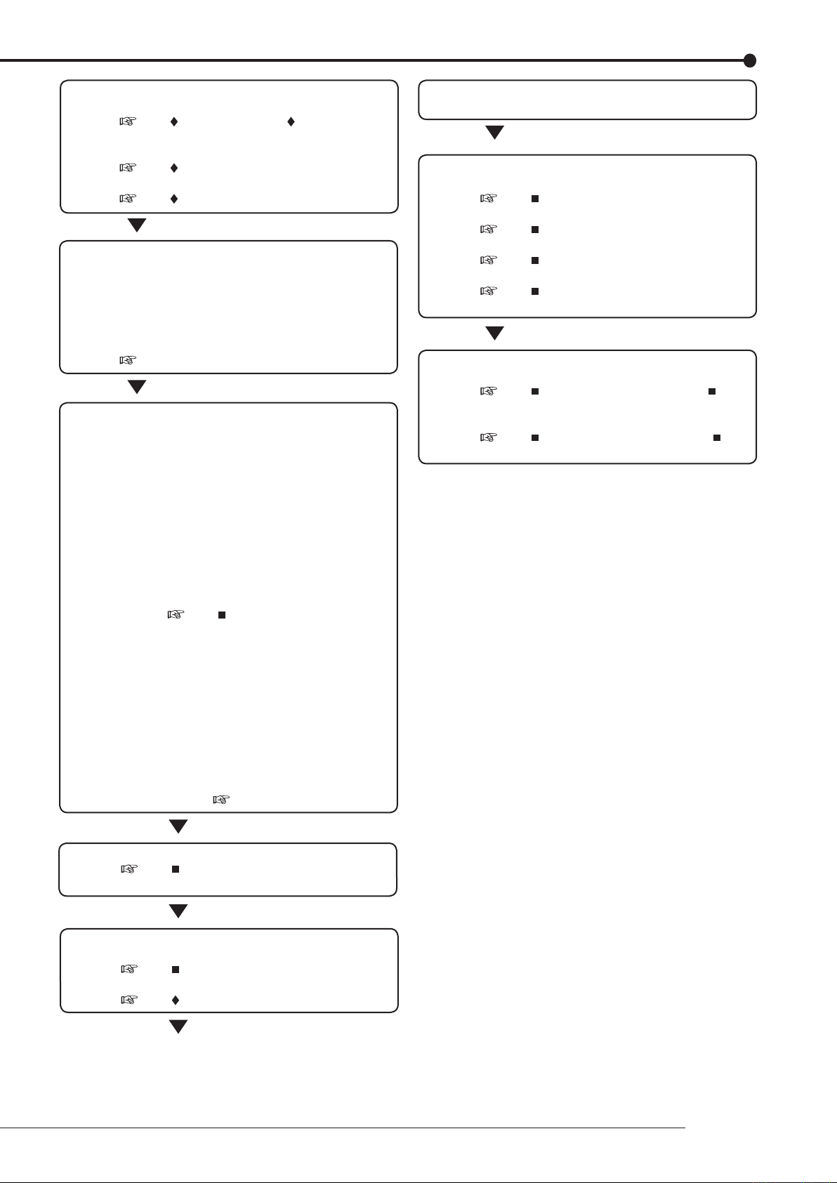
Setting other various functions
• Setting the camera title/recorder title.
See “ Camera Title” and “ Recorder Title”
on pages 67, 68.
• Setting the display mode.
See “ On Screen Information” on page 67.
• Setting the output signal of the unit status.
See “ Mode Out Settings” on page 58.
Setting the motion detection
• Selecting the camera number.
• Setting the detection areas.
• Setting the sensitivity.
• Setting the minimum number of dots for starting
the motion detection operation.
Setting the detection interval.
•
See “Motion Det” on page 56.
Setting the timer recording
• Setting the normal/alarm recording or pre-alarm
recording.
Setting the recording rate/picture grade for
•
normal recording.
Setting the recording rate/picture grade for alarm
•
recording.
Setting the motion detection recording.
•
Selecting the camera selection during the alarm
•
recording and trigger for alarm recording.
Setting the alarm recording time.
•
Setting the pre-alarm recording time.
•
Setting the PTZ camera preset.
•
See “ Set Recording Pattern A
(Normal/Timer) to D (Timer)” on page 49.
• Setting the timer program.
Setting the holiday.
•
Selecting the timer program number.
•
Making the timer recording settings.
•
Selecting the day of the week.
•
Selecting the start time.
•
Selecting the end time.
•
Selecting the program mode.
•
Selecting the motion detection mode.
•
Selecting the special day of the week.)
(
•
See “Timer” on page 54.
The search is completed and the search result is
displayed
Playback the search result
• Selecting the camera number to be played back.
See “ Multiplexer Setting” on page 64.
• Selecting the split/sequence screen.
See “ Multiplexer Setting” on page 64.
• Playback the recorded data.
See “ Basic playback” on page 92.
• Selecting the playback speed.
See “ Various playback functions” on page
80.
Copy the data
• Setting the copy device.
See “ Add/Remove HDD Device” or “ Add/
Remove DVD/CD Drive” on pages 75, 76.
• Setting the copy function.
See “ Copy Data to Copy 1 Drive” or “
Copy Data to Copy 2 Drive” on pages 41, 42.
Timer recording is executed and completed
See “ Warnings and their appropriate
countermeasures” on page 108.
Searching the recorded data
• Setting the device to be searched.
See “ Select Source Device” on page 39.
• Setting the alarm list search.
See “ Search by Alarm List” on page 94.
Beginning
11
1 3 4 5 6 7 8 9 10 11 12
19 20
21
151413 162
17
18
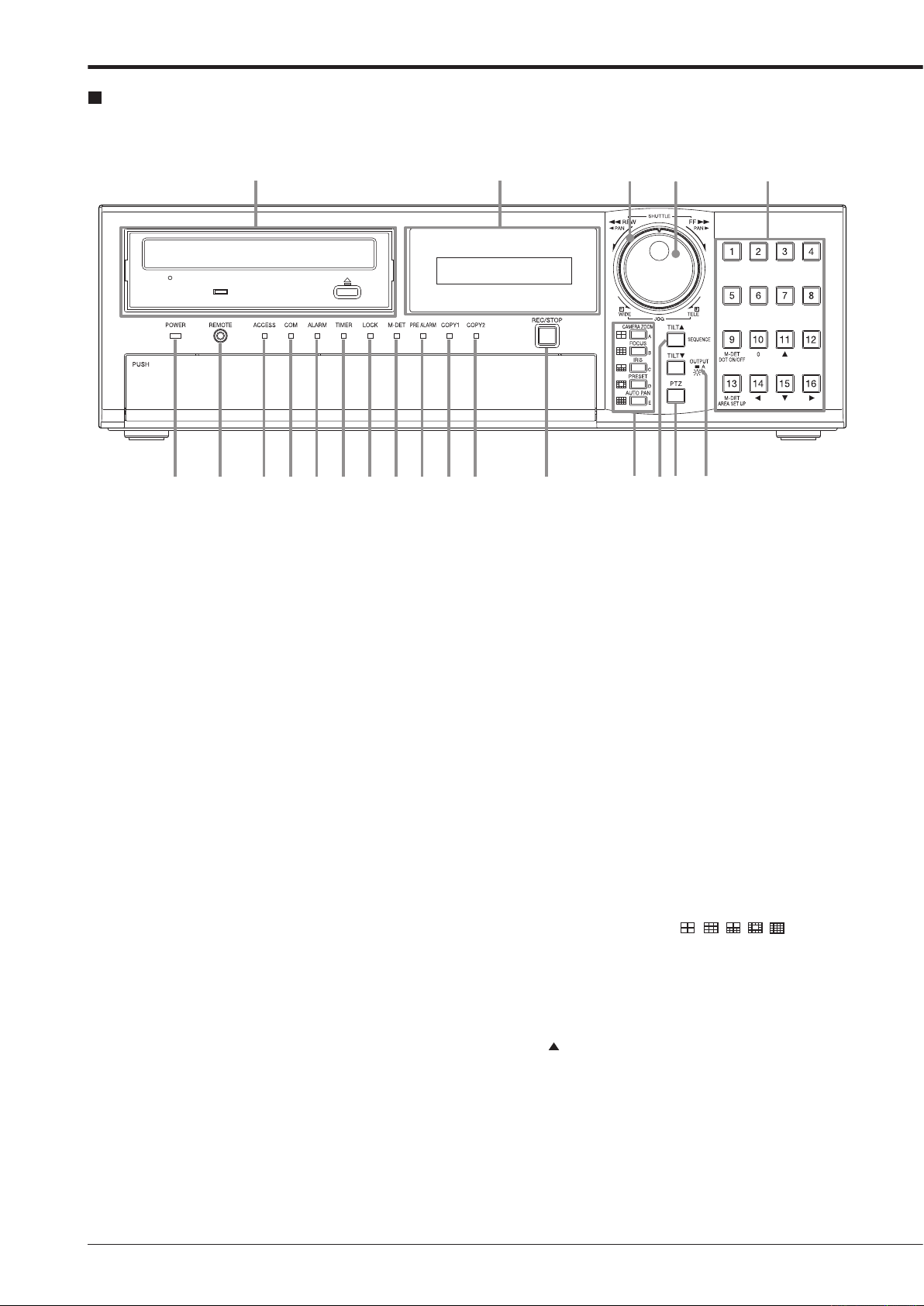
Major operations and their functions
Front view
1. POWER indicator
Illuminates when the unit is ON (MAIN switch on the
rear is ON and the POWER button in the front has been
pressed.) Turns off when the unit is in stand by mode
(only rear switch is ON) or MAIN switch on the rear is
turned off. It takes about 1 or 2 minutes from pressing
the POWER button to switch the unit ON. When the unit
is in operational transition such as boot-up, the indicator
flashes and other operations are not accepted.
2. REMOTE jack
Input connector for optional wired remote controller.
3. ACCESS indicator
Illum i nate s duri n g acc e ssing to inte r nal HDD or
peripheral recording devices. Press the POWER button
after the ACCESS indicator is turned off and “POWER
OFF” is displayed on the LCD display.
4. COM (COMMUNICATION) indicator
Illuminates when establishing the communication with
personal computer.
5. ALARM indicator
Illuminates during alarm recording.
6. TIMER indicator
Illuminates during timer recording or timer recording
stand-by mode.
7. LOCK indicator
Illuminates while simple lock or password lock is turned
on.
9. PRE ALARM indicator
Illuminates during pre-alarm recording.
It also illuminates when pre-alarm recording has been
set.
10. COPY 1 indicator
Illuminates while performing copy 1 operation.
Flashes when starting or ending the copy 1 operation.
11. COPY 2 indicator
Illuminates while performing copy 2 operation.
Flashes when starting or ending the copy 2 operation.
12. REC/STOP button
Starts recording. The button lights up during recording.
When pressing the button for more than 2 seconds, the
recording stops and the light turns off.
When pressing this button for more than 2 seconds during alarm recording, recording stops.
timer recording, recording does not stop even if
During
the button is pressed.
13. SPLIT screen buttons (
Selects split screen to be displayed.
Used for the menu settings.
)
14. SEQUENCE button
Used to select and display the sequential screens.
TILT button
When pressing the button during PTZ mode, the angle
of the camera adjusts in the upward direction.
8. M-DET indicator
Illuminates when the motion detection function is activated.
Flashes during motion detection recording.

15. PTZ (Pan, tilt, and zoom) button
Switches this unit to PTZ mode to control the PTZ camera connected.
Camera control buttons
The following buttons control PTZ motion during PTZ
mode. This unit must be in single screen display.
CAMERA ZOOM button
Adjusts the camera zoom. Press this button and then
turn JOG to the left (wide) or right (tele) to adjust the
camera zoom.
FOCUS button
djusts the focus of a camera. Press this button and
A
then turn JOG to the left (far) or right (near) to adjust the
focus.
IRIS button
Adjusts
turn JOG to the left (close) or right (open) to adjust the
iris.
PRESET button
Presets
then press the camera number button within 3 seconds
to preset the points.
AUT
Activates auto pan of the camera connected.
the iris of a camera. Press this button and then
up to 16 viewing positions. Press this button and
O PAN button
21. Camera number buttons (1 to 16)
Displays the picture supplied from the camera connected. The number of the button corresponds to that of the
CAMERA IN connector on the rear panel. The button of
the displayed camera number lights up.
Used for the preset function of the PTZ camera control.
Used for the menu settings.
M-DET DOT ON/OFF/M-DET AREA SET UP
(camera number 9 and 13)
Used for setting the detection area of the motion detection function.
16. OUTPUT A/B button
Switches the multiplexer output between A and B. The
light turns off when OUTPUT A is selected and on when
OUTPUT B is selected. It affects both, playback and
search functions. The menu cannot be displayed when
this button is illuminated.
TILT button
When pressing the button during PTZ mode, the angle
of the camera adjusts to the downward direction.
17. Disc loading slot
Accepts DVD disc or CD to copy/back up.
The supported discs are:
W, DVD-R, CD-R, and CD-RW
DVD-R
OPEN/CLOSE button
Opens or closes the disc loading slot.
BUSY indicator
Flashes or illuminates during recording or playback.
18. LCD display
Displays the present time and the status of the unit.
19. SHUTTLE ring
Adjusts the playback speed, and rewinds or forwards the
recorded pictures.
Pans the camera.
20. JOG dial
Forwards or rewinds the picture during playback (frameby-frame).
Uses for controlling PTZ cameras connected.
Beginning
13

22 24 29 30
31
32
25 26
27
28
3323
Major operations and their functions (continued)
Front view (inside of the door)
22. POWER button
Turns on the unit (MAIN switch on the rear of this unit
must be ON). When the button is pressed again, the unit
switches to stand-by mode. The POWER and other but-
operations are not accepted while the POWER indi-
ton
cator is flashing.
23. ANALOGUE OUTPUT connectors
VIDEO OUT connector
Output connector for video signal (RCA pin).
AUDIO OUT connector
Output connector for audio signal (RCA
pin).
24. SERIAL BUS port
Input and output port for the devices equipped with SERIAL BUS connectors. Bus power cannot be used.
25. HELP button
Displays the help menu (for caution on use, operating
method, and explanation on functions).
Used when the warning message is displayed.
button can be used even while the menu screen is
This
displayed.
26. SET UP button
Displays the <User Menu>.
29. LOCK button
Activates simple lock or password lock when pressing
while the MAIN switch (main power) on the rear panel is
turned on and lights up the LOCK indicator. Moreover,
the password can be set on the <Password Setting> (
page 60).
30. TRIPLEX PB button
In split screen display, inserts the playback picture of
needed camera while also displaying the live picture
from other camera.
31. BOOK MARK button
When pressing this button during frame still playback of
the single screen display, the selection screen appears
to register the bookmark or to copy the picture being displayed.
32. DIGITAL ZOOM button
Pressing this button in single screen display displays the
screen in 100 % magnification (live or playback). Press-
the camera number button (11, 14, 15, or 16) moves
ing
the magnification centre point.
27. SEARCH button
Displays the <User Menu> with search menu opened.
28. TIMER button
Sets the unit to timer recording/stand-by mode and lights
up the TIMER indicator. When pressing this button for
more than 2 seconds, timer recording/stand-by mode is
cancelled and the TIMER indicator is turned off.

33. Operation buttons
STOP button
Stops playback.
P
AUSE/JUMP TO END button
Switches the playback to still frame playback when
pressing this button during playback. Resumes playback
when pressing the button again. The button lights up
during still frame playback.
pressed during shuttle playback, the set playback
When
speed is maintained even when letting go of the SHUTTLE ring. (Shuttle hold)
hen pressed during the unit is in stop mode of play-
W
the frame still picture around the end point of the
back,
latest recording appears. (Jump to end)
. PLAY (REVERSE PLAY) button
REV
Starts reverse playback. The button lights up during reverse playback.
Y button
PLA
Starts playback. The button lights up during playback.
SPEED (+ and –) button
witches the playback interval speed during normal or
S
reverse playback.
Loading/Ejecting a DVD or CD
Before using a disc, read the cautionary notes described
in the manual included with the disc.
step
1. Press the OPEN/CLOSE button.
• The disc loading slot opens.
[When loading the disc:]
step
2-1. Place the disc onto the tray.
• Make sure that the disc is inserted properly with
the label side up.
[When ejecting the disc:]
step
2-2. Eject the disc from the tray.
step
3. Press the OPEN/CLOSE button again.
• The disc loading slot closes.
Do not eject the disc while copying/restoring, saving/load-
ing menus, or immediately after inserting the disc. The
disc or the contained data may be damaged.
Use the disc which we recommend. When a disc other
than the recommended is used, the data may not be read
or written correctly. Consult your dealer for recommended
usable discs.
When using DVD-RW or CD-RW disc, initialize the disc
by <Data Clear> (
Although you can copy the data on DVD/CD with this unit
and playback that data on the personal computer using
the supplied application software, not all the personal
computers or DVD/CD drives are ensured for proper playback of such data.
Before using the DVD drive, check whether that the drive
supports the medium to be used. It is recommended to
use the DVD-Multi drive when you playback the data on
the personal computer.
page 79) before using.
Beginning
15
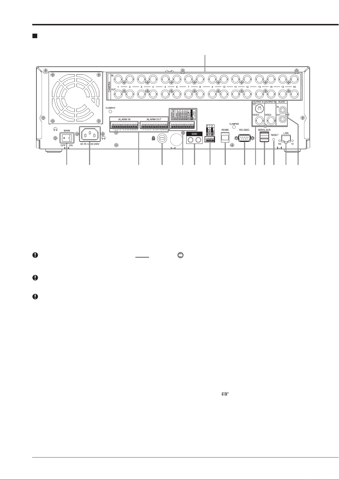
7
4
6 8 9 10 11 12 13 14 15
2
1
3
5
Major operations and their functions (continued)
Rear view
1. MAIN switch
This is the main power switch. To use this unit, set this
switch to ON. Otherwise, the front power button does not
turn the unit on/off.
2. AC power socket
Used to connect the power cord. Earth terminal is used
for safety. Use the 100 to 240 V outlet with ground terminal.
This unit must be earthed at all times. Never connect
this unit to a power outlet which does not have an earth
terminal.
Use the supplied AC power cord.
3. CAMERA connectors
Do not connect superimposed voltage camera because
it can cause damage to the unit.
CAMERA IN connectors
Input connector for video signal of camera (BNC connector).
CAMERA
Output connector for video signal of camera (BNC connector).
CAMERA IN connector is looped out to this connector.
OUT connectors
If the MAIN switch is turned on, the signal from
4. ALARM IN terminals
Input terminals for alarm signal. Alarm signal input is acceptable once a second. However, when multiple signals
are input at the same time, not all the signals may be acceptable.
ALARM OUT terminals
Output terminals for alarm signal. This terminal outputs
signal for about 2 seconds when alarm or motion detection is input to each sensor connected.
5. Keyhole for anti-theft lock
Used to connect a commercially available anti-theft cable manufactured by Kensington.
6. I/O terminals
CLOCK ADJ terminal
Input terminal to set the present time. Time display is
adjusted to the nearest hour (00 minutes 00 seconds)
when this terminal receives the signal.
The on-screen clock is reset to the nearest hour by applying a signal input of the CLOCK ADJ terminal. For
example, if the present time is 11:29:59, it is reset to
11:00:00, and if the present time is 11:30:00, it is reset
to 12:00:00.
CLOCK ADJ OUT terminal
Output terminal to set the clock of the connected record-
to the nearest hour (00 minutes 00 seconds) in sync
ers
with input of CLOCK ADJ.
REC terminal
nput terminal to start recording. This terminal is not
I
available during timer recording.
REC ST
Input terminal to stop recording. This terminal is not
available during timer recording.
EMERGENCY
Input terminal to start emergency recording immediately.
MODE OUT 1 to MODE OUT 4 terminals
Output
Select the mode of the unit to be output in the <Mode
Out Settings> (
OP terminal
terminal
terminal to inform the current mode of this unit.
page 58).

CALL OUT + terminal/CALL OUT – terminal
This is an isolation output terminal. Information to be externally
output depending on the CALL OUT settings made in the
<Call Out Settings> (
which are output regardless of the menu setting.
DC 12 V OUT terminal
Output
POWER button are turned ON. The maximum electric
current is 350 mA.
output consists of the selectable items which are
page 59) and the fixed items
the voltage only when both the MAIN switch and
7. GND terminals
Used as common ground terminal.
8. RS422/RS232C connectors
Connectors for connecting PTZ cameras to operate pan,
tilt, and zoom functions of the camera.
9. RS485 connector
Connector for controlling this unit remotely.
10. RS-232C connector
Used to connect to a host device equipped with RS232C connector (such as a personal computer). This unit
can be controlled from other devices via this connector.
11. VIDEO OUTPUT connectors
OUTPUT A VIDEO connector
Output connector which sends video signal to the monitor (BNC connector).
OUTPUT
Output connector which sends brightness signals and
colour signals separately for higher picture quality. Si-
ultaneous output along with OUTPUT A VIDEO con-
m
nector is also possible.
OUTPUT B VIDEO connector
utput connector which sends video signal to second (B)
O
monitor (BNC connector) (
A S(Y/C) connector
page 18).
12. SERIAL BUS port
Input and output port for connecting to th e device
equipped with SERIAL BUS connector. Do not use the
power control function of the external device which uses
bus power of this unit. Bus power cannot be used.
various external HDDs can be connected to this unit
The
in order to expand the memory or to use as the copy device. However
at high rate, some pictures may be missed due to the
slow rate of data transfer or the slow speed of response
from the external device connected. Be sure to check
the operation sufficiently in advance.
, during recording or playing back a picture
13. RESET button
Used to reset the unit and turn off the power. At that
time, picture data, menu settings, and the present time
are kept.
14. LAN port
Port for communication using web browser.
15. AUDIO connectors
AUDIO IN connector
Input connector for audio signal (RCA pin).
AUDIO OUT connector
Output connector for audio signal (RCA
pin).
Beginning
17
Connections
To OUTPUT A VIDEO or
OUTPUT A S(Y/C) connector
One of either codes
should be connected.
To VIDEO IN or
S(Y/C) IN connector
To VIDEO IN
connector
To OUTPUT B
connector
To CAMERA IN 1 connector
Up to 16 cameras
T
o GND
terminal
To ALARM IN terminal
corresponding to the
camera #.
To LAN
DX-ZD5UE(Z)
Up to 7 units can be mounted
at the same time.
To SERIAL
BUS
RS232C type
dome camera
(camera controller)
RS422 type
dome camera
Processing the connecting line
Connection on the ALARM IN terminals, the I/O terminals, and RS485/RS422
Compatible power lines ø0.32 — ø0.65 mm (AWG 28 — 22)
Cut the designated area from the electric wire’s outer covering
(vinyl portion).
5-7mm
Clamp the USB cable using the supplied
cable clamping band in order to prevent the
accidental removal of the cable.
( See page 20.)
Clamp the power cord using the supplied
cable clamping band in order to prevent the
accidental removal of the cable.
( See page 20.)
Dome camera
Camera #1
Monitor
Monitor
Sensor #1
PC
PC
Mouse
Power code
External recording device
PTZ control connectors
Connecting to CCTV camera, monitor, and sensor
You can connect various devices to control this unit from them, or to control them from this unit. However, depending on
the operational condition of this unit, the operational speed of this unit may become slower or control of the external device
may be delayed.
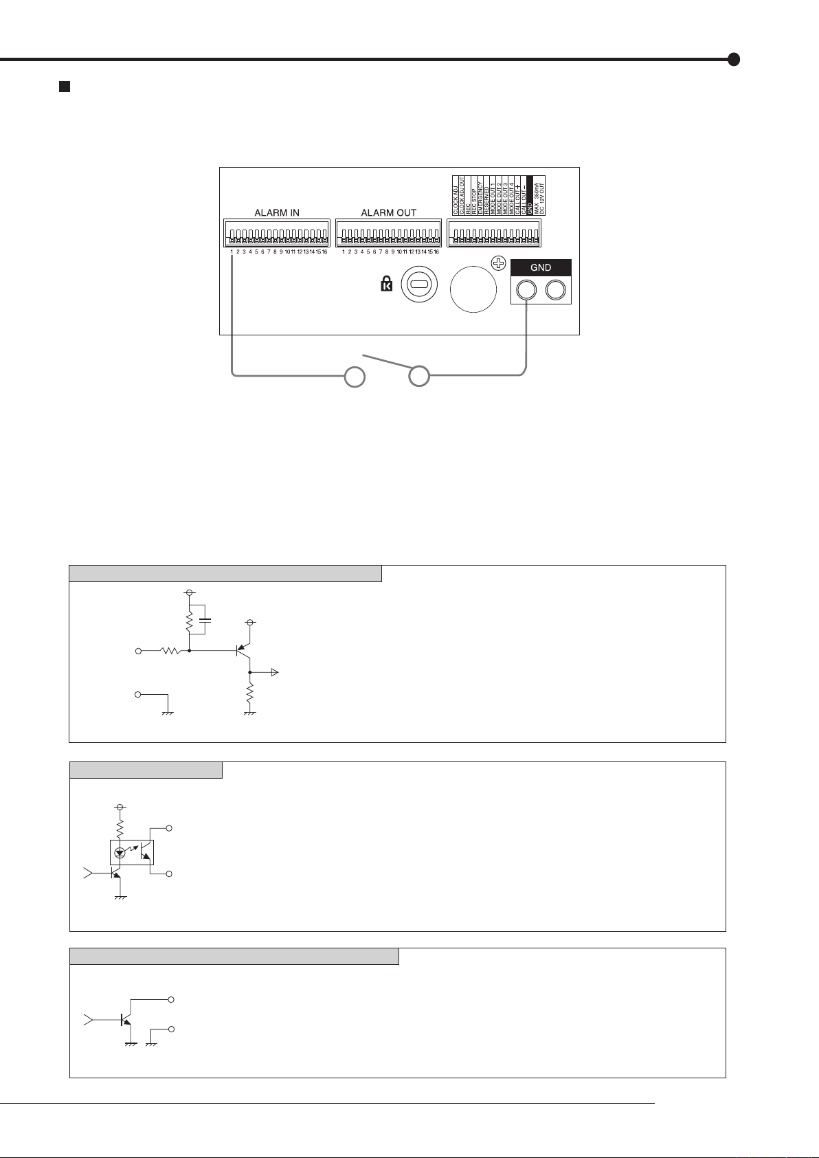
Alarm recording connection
[Input condition]
[Input interval]
[Specification]
[Specification]
[Specification]
CALL OUT output terminal
ALARM OUT/MODE OUT 1 to 4/CLOCK ADJ output terminals
EMERGENCY/ALARM IN/REC/CLOCK ADJ input terminals
[Output Circuit]
[Input Circuit]
[Output Circuit]
ground of 200 ms or more
1 second or more
Active: When terminals are short-circuited or “Low” Level is applied.
Non active: Open.
Warning signal (Photo coupler output)
Active: Short Max. Drive current 7 mA DC.
Non active: Open. Max. Voltage +24 V DC.
Active: “Low” Level Max. Drive current 30 mA DC.
Non active: Open. Max. Voltage +24 V DC.
* Be sure to use these terminals within above rated value.
<Interface circuit inside of the unit>
5V
5V
10kΩ
22kΩ
Input
terminal
0.047µF
GND
4.7kΩ
<Interface circuit inside of the unit>
CALL OUT + terminal
CALL OUT — terminal
<Interface circuit inside of the unit>
Output terminal
GND terminal
The diagram below shows an example connection for setting alarm signal to sensor number 1.
Connections
19
Connections (continued)
To VIDEO IN
connector
To AUDIO IN
connector
Analogue video cassette recorder
To VIDEO OUT
connector
To AUDIO OUT
connector
Commercially available audio cable
Commercially available video cable
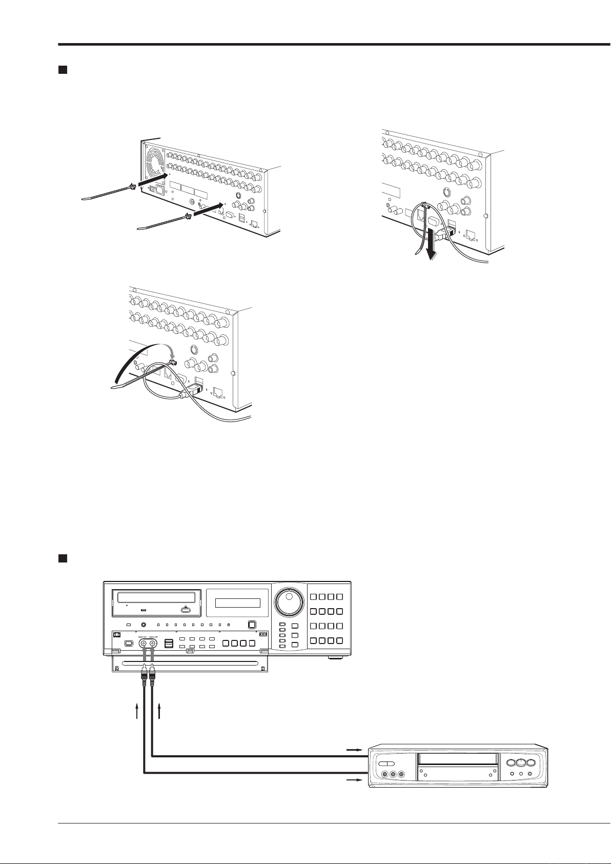
Clamping the cables
step
1. Put the supplied cable clamping band into the
clamper hole on the rear panel.
• There are 2 clamper holes on the unit, for power
cable and USB cable.
step
2. Put the cable to be clamped through the cable
clamping band as illustrated below.
• Face the serrated surface of the band inside.
step
3. Pull the edge of the cable clamping band until it
stops.
Connecting to an analogue video cassette recorder

Optional items
DX-ZD5UE(Z)
HDD extension unit (serial bus connection type)
various external HDDs can be connected to this unit in
The
order to expand the memory or to use as the copy device.
However, during recording or playing back a picture at high
rate, some pictures may be missed due to the slow rate of
data transfer or the slow speed of response from the external
device connected. Be sure to check the operation sufficiently
in advance.
not use the power control function of the external device
Do
which uses bus power of this unit.
DX-RM5(ZD)
Rack mount adapter for HDD extension unit DX-ZD5UE(Z).
DX-KB5UE
Keyboard for digital recorder
R-2500
Wired remote controller
setting, search, and PTZ preset function are not avail-
(Menu
able with wired remote controller
Consult your dealer for the functions related to PTZ.
DX-RM4
Rack mount adapter for digital recorder DX-TL4516 series.
.)
Recommended items
Consult your dealer about the recommended external devices.
he external device to be used may be unsuitable for the
T
operation you want to set. It is recommended to consult your
dealer when using the external device.
various external HDDs can be connected to this unit in
The
order to expand the memory or to use as the copy device.
However, during recording or playing back a picture at high
rate, some pictures may be missed due to the slow rate of
data transfer or the slow speed of response from the external
device connected. Be sure to check the operation sufficiently
in advance.
Connections
21
How to set the menus
Setting the menus
The operations of this unit can be set via a menu displayed on OUTPUT A monitor. You can select and set the menu by using
the buttons on the front panel or using a USB mouse connected to the unit. When using the front panel buttons, the numbers
1-16 (camera number buttons) and letters A to E (SPLIT screen buttons) represent the GUI button of the menu screen.
The menu can only be displayed through OUTPUT A monitor. The menu cannot be displayed through OUTPUT B monitor.
Setting the menu using a mouse
Mouse is not supplied with this unit.
Left button
Wheel
Right button
Mouse
Use the standard USB mouse which has left and right
buttons as illustrated to the left. Note that you cannot
use the mouse with this unit depending on the mouse
connected.
step
1. Use the left and right mouse buttons to set the
menu.
• Click the left button to open the menu or select
a needed item, etc.
Click the right button to set the active area for
•
motion detection function. (
• The wheel on a mouse does not work with this
unit.
page 56)
Setting the menu using the front panel buttons
step
1. Use the SET UP button, camera number buttons,
and the SPLIT screen buttons (A to E) to set the
menu.
• Press the SET UP button to display the menu
screen.
Press the camera number buttons (1 to 16)
•
and the SPLIT screen buttons (A to E) to open
each menu or to select the needed item.
Displaying a menu screen
100 000 000
1
Search
2
Copy
5
Protect Data
3
Information
6
PTZ Control
D
Next
E
Exit
User Menu
Setup Menu
1
Recording
System
4
2
T
imer
Motion Det
Menu Data
5
3
D
Next
E
Exit
200 000 000
1
Recording
4
System
2
T
imer
3
Motion Det
5
Menu Data
E
Exit
Setup Menu
200 000
D
Next
E
7
6
5
4
3
2
1
Exit
Reset to Factory Setting
On Screen Display Setting
Multiplexer Setting
Password Setting
Rear T
erminal Setting
Menu Language Selection
Time/Date Setting
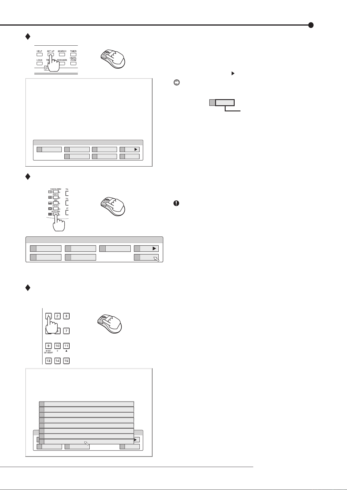
Closing a menu screen
step
1. Press the SET UP button or click the left button on
the mouse to display a menu.
• The <User Menu> appears.
• To open other menu, press the D button or leftclick on “Next
.”
When you use a mouse, click the following area to
operate.
Click this area
step
1. Press the E button or left-click on the “Exit” to close
the menu.
You cannot close the menu by pressing the SET UP
button on the unit.
Selecting an item
step
1. Press the front panel button of the needed item
number or left click on the needed item.
• The selected item menu opens.
• Select an item and press the number, or click
on the menu to open the item.
How to set the menus
23
How to set the menus (continued)
Time Date Setting
Time Date Setting
Day Light Saving Setting
Set time and date.
E
Return
241 000 000
?
A
Auto
D
Set >
0 1 — 0 1 0 62 0 00
14 16
00 00::—
Time Date Setting
Time Date Setting
Day Light Saving Setting
Set time and date.
E
Return
241 000 000
?
A
Auto
D
Set >
0 1 — 0 1 0 62 0 00
14 16
00 00::—
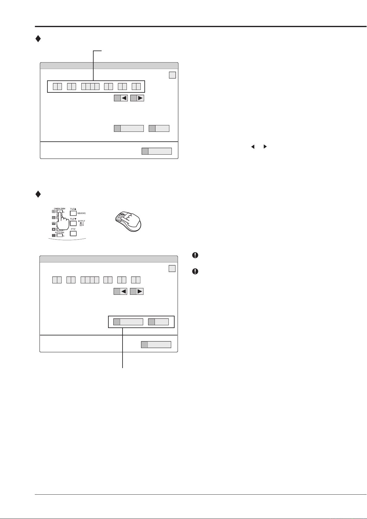
Inputting numbers
Setting parameters
Number input area
Using the front buttons of the unit:
step
1. Press the camera number buttons (0 to 9) to input
and use that number.
• The number displayed in red can be changed.
step
2. To move to the next input area, press the 16 button.
To go ba ck to the previous area, press the 14
button.
Using a mouse:
step
1. Left-click on the number in red until the needed
number appears.
To change another area, left-click on the needed
area or left-click
step
1. Press the A button or left-click on the parameter box
or .
until the item to be set appears.
• For some items, more detailed setting is
required. In this case, an item such as “D(Set
>)” is displayed. If necessary, press the D
button or left-click on the “Set >” to set more
details.
When you close the menu, press the E button or left
click on “Return” or “Exit.”
You cannot close the menu by pressing the SET UP
button on the unit.
Setting or selecting area
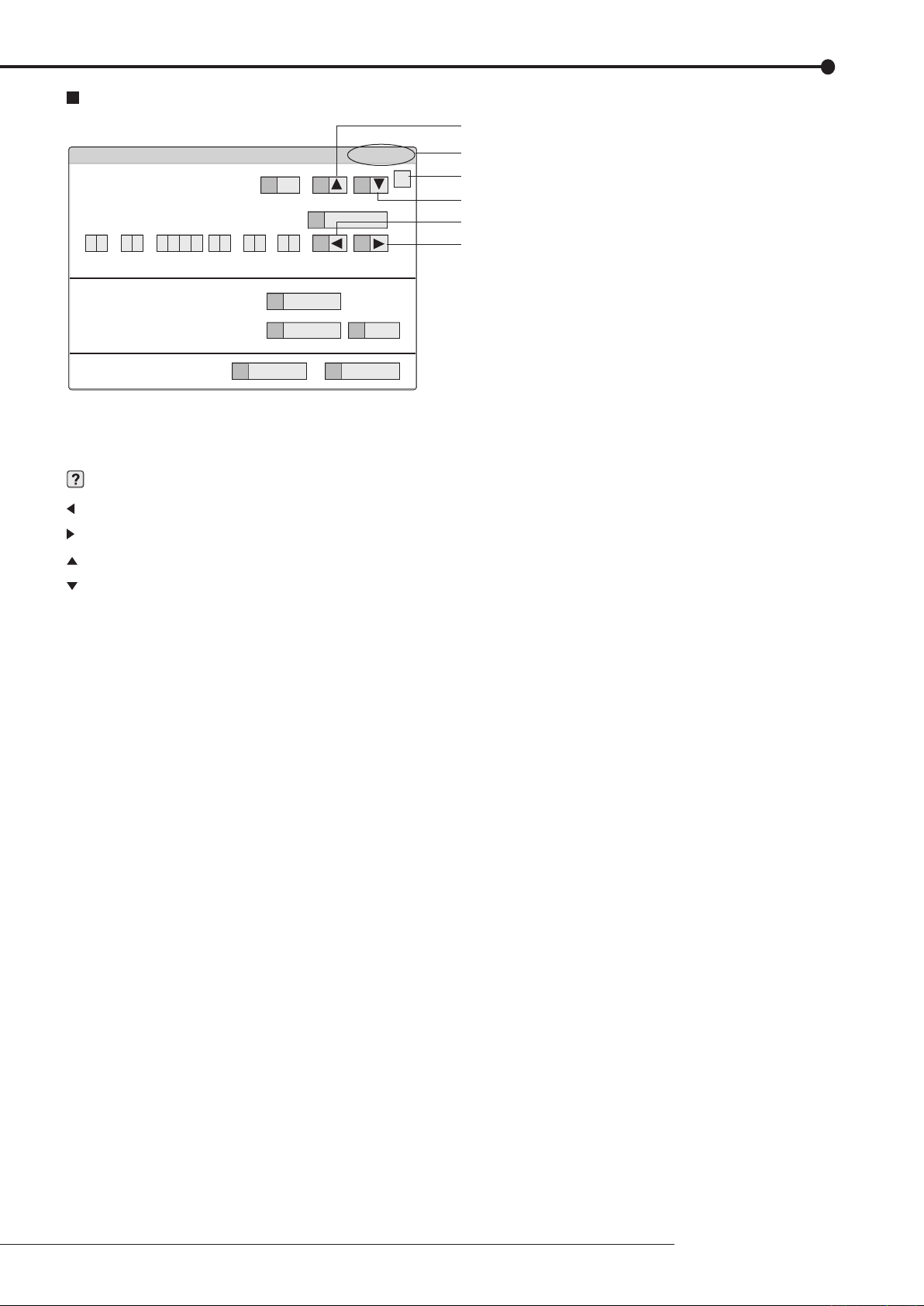
Symbols in the menus
Motion Search (Main — Normal)
E
Return
D
Search
1
16 000 000
?
Motion Detection Settings
A
1
13
Oldest
B
Next >
C
Motion A
12
same
0 1 — 0 1 0 62 0 00
14 16
00 00::—
11 15
Same as Recording Setting
Search Start Position
Setup date search starts from.
Camera Select
Up button
Menu address
Help button
Down button
Left button
Right button
Some symbols appear in the menu screens. The meanings are as follows.
(Help) When you press the HELP button or click this symbol, the detailed information on the menu appears.
(Left) When you press the 14 button or click this symbol, the item to be set shifts to left.
(Right) When you press the 16 button or click this symbol, the item to be set shifts to right.
(Up) When you press the 11 button or click this symbol, the value of selected item increases.
(Down) When you press the 15 button or click this symbol, the value of selected item decreases.
Menu address A unique number for each menu page. You can go directly to each menu page by inputting the menu ad-
dress number using the front buttons of the unit.
For example, when opening the <Motion Search> menu, press the SET UP button and then press the cam-
era number button in the order of 1, 6.
How to set the menus
25

Setup Wizard
Turn on the power for the first time
Select whether or not to use Setup Wizard
step
3
step
2
step
4
D
D
A+C
step
5-1
step
5-2
D
2
1
2
2
D
D
D
D
step
7
step
8
step
9
step
10
step
6-1
step
6-2
5
C
D
step
11
Language Selection
Time Date Adjust
Day Light Saving
HDD Connection
HDD Selection
Detailed setting (Internal HDD)
Detailed setting (serial bus HDD)
HDD Configuration
Partition setting
Select whether or not to set normal recording conditions
Recording Setup
(step 3 Confirm recording settings for each camera)
Camera settings overview
Recording Setup (step 1 Camera check)
Recording Setup
(step 2 Define regular recording cycle)
Finish
Setup Wizard
The setup wizard is displayed when the unit is turned on for
the first time. The Wizard enables a quick setup.
Only when the unit is turned on for the first time, the setup
wizard screen is displayed automatically. It is not displayed next time the unit is turned on.
step
1. After connecting the cameras and the monitors, turn
on the MAIN switch on the rear panel and wait until
the ACCESS indicator is turned off, then press the
POWER button on the front panel.
• The <Setup Wizard> screen appears.
The POWER button does not operate while the ACCESS
indicator is flashing. Press the POWER button after the
indicator is turned off and “POWER OFF” is displayed on
the LCD display on the front panel.
step
2. Select whether or not to use the setup wizard.
• Select “Go” when you want to use the setup
wizard. If not, select “Quit.” When selecting
“Quit,” the clock starts running from the initial
setting.
Beware that the menu screen cannot be exited while set-
ting the setup wizard. Furthermore some menu screens
which have already been set are not displayed again.
step
3. (When selecting “Go”)
Select the desired language.
• The <Language Selection> screen appears. The
language of the menu can be selected in this
screen.
Select the desired language and then select
•
“Execute” when you have changed the setting.
The unit restarts when selecting “Execute.”
Select “Next” when the language setting does
•
not have to be changed.
step
4. Set the present time and daylight saving setting.
page 58)
(
• Select “Next” when the setting is completed.
The clock start running when exiting this screen.
step
5-1. Set the connected HDD.
• When you use only the internal HDD, select
“Internal” and then select “Next.”
When you use the external HDDs, select “Int +
•
Ext” and then select “Setting” to set the detailed
setting for each HDD.
step
5-2. (When selecting “Setting”)
Make the detailed setting for internal and serial bus
HDDs.
• In the detailed setting screen, select “Main” and
“Copy2” to use the selected HDD as the main
device and copy 2 device respectively. Select
“Free” when the selected HDD is not used as
the main or the copy 2 device.
When the setting is completed, return to the
•
screen of step 5-1 and then select “Next.”
step
6-1. Set the HDD configuration.
Normal: Does not set partition.
Partition: Sets an independent partition for alarm
recording within the total HDD memory. When
selecting “Partition,” set the partition capacity.
• Select “Next” when selecting “Normal.”
• Select “Setting” to set the partition capacity
when selecting “Partition.”
Loading…
DX-TL4516U
16-Channel Digital Video Recorder
With JPEG2000 Video Compression
Key Features
■JPEG2000 video compression for superb video quality
■960 PPS live/120 PPS record
■Built — in integrated CD/DVD drive for easy copy
■Auto set up for automated programming
■Multiple HDD options
■Dual multiplexer outputs for simultaneous live/record on two monitors
■Advanced motion detection up to 418 detection dots
■PTZ of dome cameras
■Various search options
■Built — in network for remote view and programming
Versatile Monitoring, Superb Reliability And User Friendly Set Up
The DX-TL4516U is a 16 video input stand alone digital video recorder based on JPEG2000 video compression. Sharing many features with Mitsubishi’s ultra — high spec DX-TL5000U recorder, the DX-TL4516U is smaller in size and more cost effective yet offers an array of advanced features critical in today’s security market. Utilizing JPEG2000 video compression, the DX-TL4516U offers pristine real time live images displayed at 960 pictures per second and high density recording is possible at a rate of 120 pictures per second. Compared to wavelet compression, JPEG2000 also reduces hard disc drive consumption while provid- ing superior image quality for optimal recording.
Image copy with the DX-TL4516U is simple with it’s built in CD/DVD drive. Other features include USB mouse supported GUI for easy programming, advanced motion detection and PTZ of dome cameras. With use of the included DX-PC55U software, monitoring, playback and full programming is possible from remote locations. Options include a security controller keyboard and USB enabled HDD expansion units that can offer terabytes of additional storage. Advanced, easy to use and highly reliable, the DX-TL4516U offers the performance for secure
24/7 digital video surveillance.
Panel Open
Русский
- Bedienungsanleitung Mitsubishi Electric DX-TL4516U
- Mitsubishi Electric DX-TL4516U User Manual
- Manual Usuario Mitsubishi Electric DX-TL4516U
- Mode d’emploi Mitsubishi Electric DX-TL4516U
- Istruzioni Mitsubishi Electric DX-TL4516U
- инструкция Mitsubishi Electric DX-TL4516U
- Mitsubishi Electric DX-TL4516Uの取扱説明書
- Handleiding Mitsubishi Electric DX-TL4516U
- Manual de uso Mitsubishi Electric DX-TL4516U
Вам нужна инструкция? Мы поможем Вам ее найти и сэкономить Ваше время.
- 2 stron
- 0.24 mb
Изделие Mitsubishi Electric DX-TL4516U, а также другие, которыми Вы пользуетесь ежедневно, наверняка вы получили в комплекте с инструкцией обслуживания. Из опыта наших пользователей мы знаем, что большинство из Вас не уделили этому особого внимания. Большая часть инструкций, сразу же после покупки попадает в корзину для мусора вместе с коробкой — это ошибка. Ознакомьтесь с информацией, касающейся инструкции Mitsubishi Electric DX-TL4516U, которая поможет Вам в будущем сэкономить нервы и избежать головной боли.
Важная подсказка — не забывайте хотя бы раз прочитать инструкцию Mitsubishi Electric DX-TL4516U
Если вы не хотите каждый раз читать информационные брошюры, касающиеся, тех или Mitsubishi Electric DX-TL4516U иных изделий, достаточно, прочитать их раз — сразу же после покупки устройства. Вы получите основное знания, касающиеся поддержания изделия Mitsubishi Electric DX-TL4516U в хорошем эксплуатационном состоянии, так, чтобы без проблем достигнуть его планируемого цикла работы. Затем инструкцию можно отложить на полку и вернуться к ней только в случае, если вы не уверены, правильно ли проводится техобслуживание изделия. Правильный уход является необходимым элементом Вашего удовольствия Mitsubishi Electric DX-TL4516U.
Раз в году пересмотрите шкафчик, в котором держите инструкции для всех устройств, — выбросите те, которыми вы уже не пользуетесься. Это поможет Вам сохранять порядок в своей домашней базе инструкций обслуживания.
Summary of Contents for Mitsubishi Electric DX-TL4516U
Что находится в инструкции Mitsubishi Electric DX-TL4516U? Почему стоит ее прочитать?
- Гарантия и подробности, касающиеся техобслуживания изделия
Хорошей идеей будет прикрепить чек к странице инструкции. Если что-то плохое случится во время использования Mitsubishi Electric DX-TL4516U, у вас будет комплект документов, необходимый для гарантийного ремонта. В этой части инструкции вы найдете информацию об авторизованных сервисных центрахMitsubishi Electric DX-TL4516U а также, как самостоятельно правильно ухаживать за оборудованием — так, чтобы не потерять гарантийных прав. - Указания по монтажу и Setup
Не терять нервов и времени на самостоятельную попытку установки и первого запуска изделия. Воспользуйтесь рекомендациями производителя Mitsubishi Electric DX-TL4516U чтобы правильно запустить изделие, без лишнего риска повреждения оборудования. - Информация, касающаяся дополнительных запчастей (входящих в комплект а также являющихся опцией)
Пересматривая эту часть документа вы сможете проверить, доставлен ли ваш Mitsubishi Electric DX-TL4516U с полним комплектом аксессуаров. Вы также сможете узнать, какие дополнительные запчасти или аксессуары для Mitsubishi Electric DX-TL4516U Вы сможете найти и докупить к своему устройству. - Troubleshooting
Самые частые проблемы, касающиеся Mitsubishi Electric DX-TL4516U и методы их решения. Это очень полезная часть руководства по обслуживанию — она позволит Вам сэкономить много времени на поиск решений. 90% проблем с Mitsubishi Electric DX-TL4516U повторяется у многих пользователей. - Требования, касающиеся питания и энергетический класс
Информация, касающаяся количества потребляемой энергии, а также рекомендации, касающиеся установки и питания Mitsubishi Electric DX-TL4516U. Прочитайте, чтобы оптимально пользоваться Mitsubishi Electric DX-TL4516U и не использовать большего количества ресурсов, нежели это необходимо для правильной работы изделия. - Специальные функции Mitsubishi Electric DX-TL4516U
Здесь вы можешь узнать, как персонализировать изделие Mitsubishi Electric DX-TL4516U. Вы узнаете, какие дополнительные функции могут помочь Вам удобно использовать продукт Mitsubishi Electric DX-TL4516U а также, какие функции Вашего устройства оптимальны для выполнения конкретной деятельности.
Как видите в инструкции вы найдете информацию, которая реально поможет Вам в использовании Вашего изделия. Стоит с ней ознакомиться, чтобы избежать разочарований, возникающих из более короткого, нежели предусматривалось, периода исправности изделия Mitsubishi Electric DX-TL4516U. Если все же вы не хотите копить инструкции в своем доме, наш сайт поможет Вам в этом — вы должны найти у нас руководство по обслуживанию большинства из своих устройств, а также Mitsubishi Electric DX-TL4516U.
Комментарии (0)
- Topics
- manualsonline, manuals, mitsumi_electronics,
- Collection
- manuals_contributions; manuals; additional_collections
- Language
- English
- Item Size
- 2.9M
- Addeddate
- 2020-09-06 04:45:25
- Identifier
- manualsonline-id-cad09545-27bd-4e56-a60d-d579fdf90e3d
- Identifier-ark
- ark:/13960/t40s92477
- Ocr
- ABBYY FineReader 11.0 (Extended OCR)
- Ppi
- 600
- Scanner
- Internet Archive Python library 1.9.4
plus-circle Add Review
plus-circle Add Review
comment
Reviews
There are no reviews yet. Be the first one to
write a review.
25
Views
DOWNLOAD OPTIONS
download 1 file
ABBYY GZ download
Temporarily Unavailable
DAISY
For users with print-disabilities
Temporarily Unavailable
EPUB
download 1 file
FULL TEXT download
download 1 file
ITEM TILE download
download 1 file
PAGE NUMBERS JSON download
download 1 file
PDF download
download 1 file
SINGLE PAGE PROCESSED JP2 ZIP download
download 1 file
TORRENT download
download 12 Files
download 6 Original
SHOW ALL
IN COLLECTIONS
Manuals: Contributions Inbox
The Manual Library
Additional Collections
Uploaded by
chris85
on
-
Страница 1
1 ENGLISH DEUTSCH FRANÇAIS ESP AÑOL IT ALIANO NEDERLANDS OTHERS DIGIT AL RECORDER USERʼS MANUAL MODEL DX-TL4516E THIS INSTRUCTION MANUAL IS IMPORT ANT T O YOU. PLEASE READ IT BEFORE USING YOUR DIGIT AL RECORDER.[…]
-
Страница 2
2 Caution and care HEA VY OBJECTS SHOULD NEVER BE PLACED ON THE UNIT (E.G., MONIT OR) NEVER TOUCH OR INSERT ANY OBJECT INSIDE THE UNIT T ouching the inside of the cabinet or inserting foreign objects of any kind through the disc loading slot or ventilation holes not only creates a safety hazard but can also cause extensive damage. PROTECT THE POWER[…]
-
Страница 3
3 Beginning ENGLISH Note: This symbol mark is for EU countries only . This symbol mark is according to the directive 2002/96/EC Article 10 Information for users and Annex IV . Y our MITSUBISHI ELECTRIC product is designed and manufactured with high quality materials and components which can be recycled and reused. This symbol means that electrical […]
-
Страница 4
4 INST ALLA TION LOCA TION AND HANDLING • Place this unit horizontally and in a stable place. If this unit is not placed correctly and used in an unstable place, the unit may be damaged such as removal of the DVD/CD disc. • Do not place this unit close to other electronic or magnetic equipment. This will avoid video and audio distortion. • Wh[…]
-
Страница 5
5 Beginning ENGLISH Contents How to read this manual Viewing displays (Refer to this information when operating): Reference information concerning operation (Caution required): Cautionary items concerning operation Finding desired information There is a “ Contents ” at the beginning of this manual. T roubleshooting Read T roubleshooting (pages […]
-
Страница 6
6 Note Thank you for purchasing Mitsubishi digital recorder DX-TL4516E (hereinafter referred to as “ Product ” ). Before using this Product, please be sure to read the following Software License Agreement with regard to the software contained in this Product (hereinafter referred to as “ Licensed Software ” ). By using this Product, you are[…]
-
Страница 7
7 Beginning ENGLISH This Software License Agreement (“Agreement”) is an agreement between you (“User ”) and Mitsubishi Electric Corporation (“Licensor”) with regard to the license to use Licensed Software. Article 1 (Grant of license) Licensor hereby grants to User a nonexclusive, nontransferable license to use Licensed Software. Articl[…]
-
Страница 8
8 How to set the menus Setting the menus The operations of this unit can be set via a menu displayed on OUTPUT A monitor . Y ou can select and set the menu by using the buttons on the front panel or using a USB mouse connected to the unit. When using the front panel buttons, the numbers 1-16 (camera number buttons) and letters A to E (SPLIT screen […]
-
Страница 9
9 How to set the menus ENGLISH Displaying a menu screen step 1. Press the SET UP button or click the left button on the mouse to display a menu. • The <User Menu> appears. • T o open other menu, press the D button or left- click on “Next .” When you use a mouse, click the following area to operate. Closing a menu screen step 1. Press […]
-
Страница 10
10 How to set the menus (continued) Inputting numbers Using the front buttons of the unit: step 1. Press the camera number buttons (0 to 9) to input and use that number . • The number displayed in red can be changed. step 2. T o move to the next input area, press the 16 button. T o go back to the previous area, press the 14 button. Using a mouse:[…]
-
Страница 11
1 1 How to set the menus ENGLISH Symbols in the menus Some symbols appear in the menu screens. The meanings are as follows. (Help) When you press the HELP button or click this symbol, the detailed information on the menu appears. (Left) When you press the 14 button or click this symbol, the item to be set shifts to left. (Right) When you press the […]
-
Страница 12
12 Setting the time and date T ime/Date Setting This item is used to set the present date, time, and auto day- light saving. Auto daylight saving function is used to automati — cally gain the clock of the unit an hour for the specified time period. Start/end time of the auto daylight savings can be checked and if needed, changed. Before you start […]
-
Страница 13
13 Basic operations ENGLISH Basic multiplexer functions This function is used to activate multiplexer functions using the buttons on the front panel. Camera number buttons DIGIT AL ZOOM button SPLIT screen buttons Move buttons SEQUENCE button OUTPUT A/B button Multiplexer buttons 1. Camera number buttons (1 to 16) Displays the picture supplied from[…]
-
Страница 14
14 Controlling the camera This function is used to control the cameras connected via RS-232C or RS-422/485 terminal. PTZ control using the menu 1 2 PTZ Control 6 step 2 step 1 step 3 step 4 Go to PTZ Control Zoom, iris, focus adjustment, AutoPan Preset Select PTZ Camera User Menu step 1. Pan or tilt the PTZ camera connected. • Click the gray area[…]
-
Страница 15
15 Basic operations ENGLISH Basic manual recording T h i s f u n c t i o n i s t o s e t u p t h e r e c o r d i n g p a r a m e t e r s o f recording settin g pattern A to start recording manual ly . Ensure all the cameras are connected and time and date has been set correctly . Before you start recording, check the repeat recording settings in th[…]
-
Страница 16
16 Basic playback This function is used to playback recorded data. This unit allows recorded data to be played back using various methods. The basic playback described below is the most common method for playback. step 1. Press the PLA Y button inside of the front door . • Playback starts. • After turning the power on, the oldest recording data[…]
-
Страница 17
17 Basic operations ENGLISH Basic search T hi s f u n ct i on i s u s ed t o s e ar c h t h e s ta r t p o in t o f n ee d e d picture. This unit is equipped with 5 search functions (Search by T ime and Date, Search by Alarm List, Find data storage location, Search by Book Mark, and Search by Motion). In this section, the common search methods, sea[…]
-
Страница 18
18 Search by Alarm List This unit stores the start time of alarm recording and emergency recording in the alarm list when such recording begins. This item is used to search the desired picture using the list of alarm recording (emergency recording). The search result displays in still frame playback of the single screen display . 3 D Search 1 steps[…]
-
Страница 19
19 Basic operations ENGLISH Copying the recorded data This item is used to copy the data from the main device to a copy device. Copy Data to Copy 1 Drive/Set Copy 1 Drive This item is used to copy the data to Copy 1 device by speci- fying the start and end points. The points are specified by the date and time or the bookmark. This function is usefu[…]
-
Страница 20
20 Copy Data to Copy 2 Drive/Set Copy 2 Drive This item is used to copy the data to Copy 2 device by speci- fying only the start point. The point is specified by the date and time or the bookmark. The copy continues until the end point of the recording data reaches or the media to be copied bec omes fu ll u nles s t he c opy is stop ped man ual ly[…]
-
Страница 21
21 Basic operations ENGLISH Copying the data of this unit to a video cassette This function is used to copy the data of this unit to a video cassette using an analogue video cassette recorder . Data can be copied even when the unit is in recording. For the recording operation, see the instruction manual for the ana — logue video cassette recorder u[…]
-
Страница 22
22 Copying the recorded data (continued) Field Reverse Click to display a still picture one field before. Stop Click to stop playback. Audio, if recorded, is played back after the stop when the audio command has been enabled. Field Advance Click to display a still picture one field after . Playback Click to playback the picture in the forward dir[…]
-
Страница 23
23 Basic operations ENGLISH In synchronized audio playback, the frequency of picture refreshing is reduced depending on the processing power of PC. When you want to playback giving priority to picture, select [Not Synchro.]. The settings on this panel remain intact for the next start- up. Audio playback channel and picture display channel are not r[…]
-
Страница 24
24 Login Start up the Microsoft Internet Explorer and log in. step 1. Start up the Microsoft Internet Explorer and enter the IP address of the recorder . • Enter the IP address which is set in <LAN (Communication) Setting> (System Menu COM/LAN). When shipped from the factory , the IP address is set to “192.168.000.100.” • The “[Logi[…]
-
Страница 25
Communications by Web Browser 25 step 3 -1 . ( I f y o u m a k e a n e r r o r i n e n t e r i n g t h e u s e r I D o r password • • • ) • The “[Caution]” screen appears. step 3 -2 . Select “Login” and either left-click or press ENTER. • The “[Login]” screen appears. step 3 -3 . Follow step 2-1 and enter the correct “User I[…]
-
Страница 26
26 Live Monitoring Retrieves live pictures and displays the pictures on the PC screen. step 1. Select “Live Monitoring” and left-click. • The “[Live]” screen appears. Wh en p ic tu re a cq ui s it io n i s t ri ed f or th e f i rs t t im e w it h the Web browser of a personal computer , a message as shown below may be displayed. If it is […]
-
Страница 27
Communications by Web Browser 27 Playback Retrieves, plays back and searches for pictures that have been recorded by the recorder . step 1. Select “Playback” and left-click. • The “[Playback]” screen appears. step 2. Press the button. • Playback starts. <Function description> : Press to start playback. : Press to start speed searc[…]
-
Страница 28
28 Alarm List Search Click “Alarm List” and the “Alarm List Search” screen appears in the sub-screen. step 1. Set the desired date/time and number of alarm list items to be acquired, and then click “Refresh” to acquire the alarm list. • The alarm list cannot be acquired without clicking “Refresh.” • Enter the needed number of al[…]
-
Страница 29
Communications by Web Browser 29 User Registration This is the screen for changing the settings for registered user authorization, and for deleting a registration. It can also be used for registering new users. step 1. Select “User Registration” and left-click. • The “[User Registration]” screen appears. step 2 -1 . (T o change registered[…]
-
Страница 30
30 Recorder Title & Camera T itles This is the screen for setting or changing the recorder and the camera titles. step 1. Select “Recorder Title & Camera T itles” and left- click. • The “[Recorder Title & Camera Titles]” screen appears. step 2. Enter the desired reco rder or camera title to “New T ext.” • The recorder an[…]
-
Страница 31
Communications by Web Browser 31 T o view the attached picture: In the PC with DX-PC55E (version 2.1 or later) installed, click or double click the file. In the PC without DX-PC55E installed, drag the file and drop it into the “MPicViewer .exe” which is stored in the supplied CD. The displayed picture can be printed or can be saved in general[…]
-
Страница 32
32 Clock Setup This is the screen for setting the clock of the recorder via PC. step 1. Select “Clock Setup” and left-click. • The “[Clock Setup]” screen appears. step 2 -1 . Set “Month,” “Date,” “Y ear ,” “Hour ,” “Min.,” “Sec.,” “T ime Zone” to the desired time. step 2 -2 . Select “set” and left-click. st[…]
-
Страница 33
Communications by Web Browser 33 Logout In this screen, assign “Logout” settings to end the job. step 1. Select “Logout” and left-click. • The “[Logout]” screen appears. step 2. Close the Web Browser . If the browser is closed incorrectly (not logging out cor- rectly), the user ’ s session ID is saved for 5 minutes. If the Log in is[…]
-
Страница 34
34 If problems with the unit persist even after you’ve followed the suggestions below , disconnect the power cord and contact the retailer from whom you purchased the unit. INST ALLA TION RECORDING Consult the following Description of problem • Is the power cord properly plugged in? • Is the LOCK indicator light on? • Is the TIMER indicator[…]
-
Страница 35
T roubleshooting 35 ENGLISH OTHERS PERIPHERAL RECORDING DEVICE Consult the following Description of problem The unit does not perform playback. The copy device dose not respond. The camera cannot be controlled via this unit. The unit does not perform the motion detection function. The unit cannot be controlled via the personal computer . There is a[…]
-
Страница 36
36 W arnings and their appropriate countermeasures #1 Options in the CALL OUT output column: • Selectable: Selects to output CALL OUT signal or not on the menu screen. • Fixed: Outputs CALL OUT signal from the CALL OUT terminal regardless of the menu setting. • None: Does not output CALL OUT signal, but displays a warning on the screen. The w[…]
-
Страница 37
W arnings and CALL OUT output 37 ENGLISH W arning Display CALL OUT output #1 Cancelling the warning Log number Countermeasure # # # LOG5 4 # 7 LOG1 3 # 8 LOG3 3 # 8 LOG4 3 # 8 LOG7 3 # 8 LOG2 3 # 8 LOG1 4 # 8 LOG7 4 # 8 LOG2 4 # 8 LOG3 4 # 8 LOG4 4 # 8 LOG55 #7 LOG6200 LOG5100 LOG5200 LOG5201 LOG5300 LOG3500#5 LOG7500#6 LOG3600#5 LOG7600#6 LOG5101 […]