
SPECIFICATIONS
MOTHERBOARD
MOTHERBOARD
H370 GAMING PLUS
H370 GAMING PLUS
GAME IN STYLE
GAME IN STYLE
FEATURES
MYSTIC LIGHT and SYNC
Personalize your PC with 16.8 million colors / 17 effects,
controlled in one click!
Turbo M.2
Running at PCI-E Gen3 x4 maximizes performance for
NVMe based SSDs.
Audio Boost
Reward your ears with studio grade sound quality for the
most immersive audio experience
Intel Turbo USB 3.1 Gen2
Powered by Intel, ensure an uninterrupted connection with
more stability and fastest USB speeds.
Model Name H370 GAMING PLUS
CPU Support
CPU Socket LGA 1151
Chipset
Graphics Interface 2 x PCI-E 3.0 x16 slots, Supports 2-way CrossFire
Display Interface DisplayPort, DVI-D — Requires Processor Graphics
Memory Support 4 DIMMs, Dual Channel DDR4 up to 2666MHz
Expansion Slots 4 x PCI-E x1 slots
Storage
USB ports 2 x USB 3.1 (Gen2, A+C) + 6 x USB 3.1 (Gen1) + 6 x USB
LAN
Audio 8-Channel(7.1) HD Audio with Audio Boost
Form Factor ATX
Supports 8th Gen Intel® Core™ / Pentium® Gold / Celeron
processors
Intel® H370 Chipset
1 x Turbo M.2 slot, supports Intel® OptaneTM Technology
5 x SATA 6Gb/s
2.0
Intel® I219-V Gigabit LAN
CONNECTIONS
GAMING LAN
Experience smooth wired gaming experience by reducing
®
CPU overhead and offer long-term network usage.
Core Boost
With premium layout and optimized power design to support
more cores and provide better performance.
DDR4 Boost
Advanced technology to deliver pure data signals for the
best gaming performance and stability.
EZ Debug LED
Easiest way to troubleshoot.
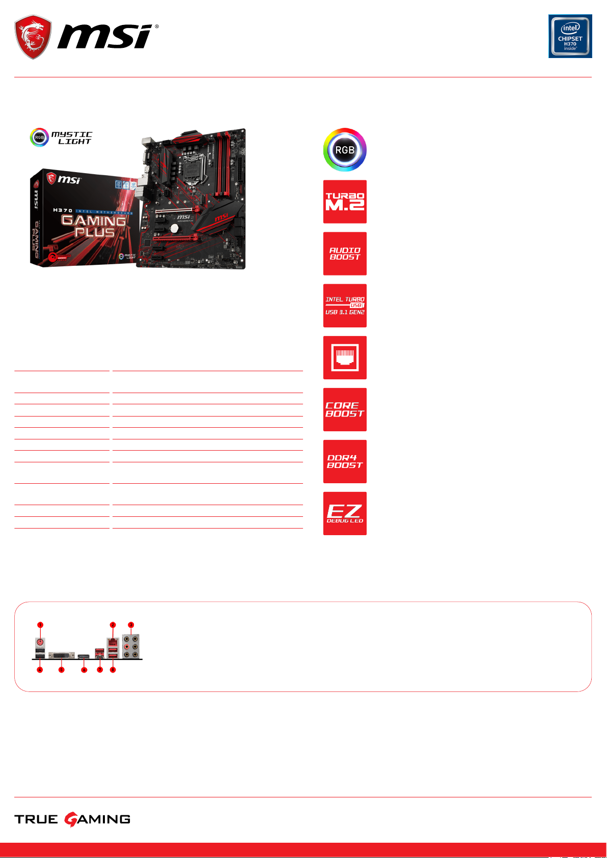
PS/2 Combo Port1.
LAN Port2.
HD Audio Connectors3.
USB 2.0 Port4.
DVI-D5.
DisplayPort6.
USB 3.1 Gen2 Type A + C7.
USB 3.1 Gen18.
© 2018 Micro-Star Int’l Co.Ltd. MSI is a registered trademark of Micro-Star Int’l Co.Ltd. All rights reserved. Intel, the Intel logo, the Intel Inside logo and Intel Core are trademarks of Intel Corporation or its
© 2018 Micro-Star Int’l Co.Ltd. MSI is a registered trademark of Micro-Star Int’l Co.Ltd. All rights reserved. Intel, the Intel logo, the Intel Inside logo and Intel Core are trademarks of Intel Corporation or its
subsidiaries in the U.S. and/or other countries.
subsidiaries in the U.S. and/or other countries.
Generated 2018-04-03, check for the latest version www.msi.com/datasheet. The information provided in this document is intended for informational purposes only and is subject to change without notice.
Loading…
1
Unpacking
Unpacking
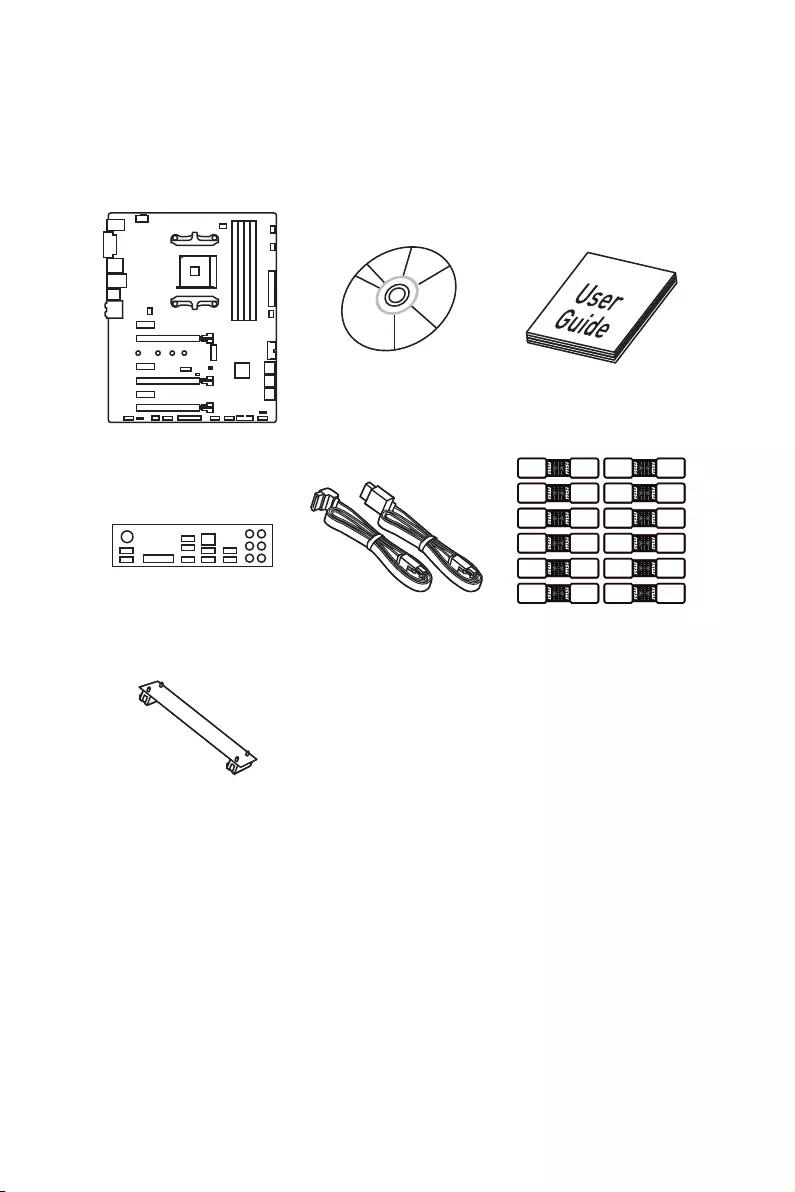
Thank you for buying the MSI® X370 GAMING PLUS motherboard. Check to make sure
your motherboard box contains the following items. If something is missing, contact
your dealer as soon as possible.
SATA Cable x2
Drivers & Utilities
Disc Motherboard User
Guide
I/O Shield
Motherboard
SATA Cable Labels
SLI Bridge
Connector

2Safety Information
Safety Information
yThe components included in this package are prone to damage from electrostatic
discharge (ESD). Please adhere to the following instructions to ensure successful
computer assembly.
yEnsure that all components are securely connected. Loose connections may cause
the computer to not recognize a component or fail to start.
yHold the motherboard by the edges to avoid touching sensitive components.
yIt is recommended to wear an electrostatic discharge (ESD) wrist strap when
handling the motherboard to prevent electrostatic damage. If an ESD wrist strap
is not available, discharge yourself of static electricity by touching another metal
object before handling the motherboard.
yStore the motherboard in an electrostatic shielding container or on an anti-static
pad whenever the motherboard is not installed.
yBefore turning on the computer, ensure that there are no loose screws or metal
components on the motherboard or anywhere within the computer case.
yDo not boot the computer before installation is completed. This could cause
permanent damage to the components as well as injury to the user.
yIf you need help during any installation step, please consult a certified computer
technician.
yAlways turn off the power supply and unplug the power cord from the power outlet
before installing or removing any computer component.
yKeep this user guide for future reference.
yKeep this motherboard away from humidity.
yMake sure that your electrical outlet provides the same voltage as is indicated on
the PSU, before connecting the PSU to the electrical outlet.
yPlace the power cord such a way that people can not step on it. Do not place
anything over the power cord.
yAll cautions and warnings on the motherboard should be noted.
yIf any of the following situations arises, get the motherboard checked by service
personnel:
Liquid has penetrated into the computer.
The motherboard has been exposed to moisture.
The motherboard does not work well or you can not get it work according to user
guide.
The motherboard has been dropped and damaged.
The motherboard has obvious sign of breakage.
yDo not leave this motherboard in an environment above 60°C (140°F), it may damage
the motherboard.
3
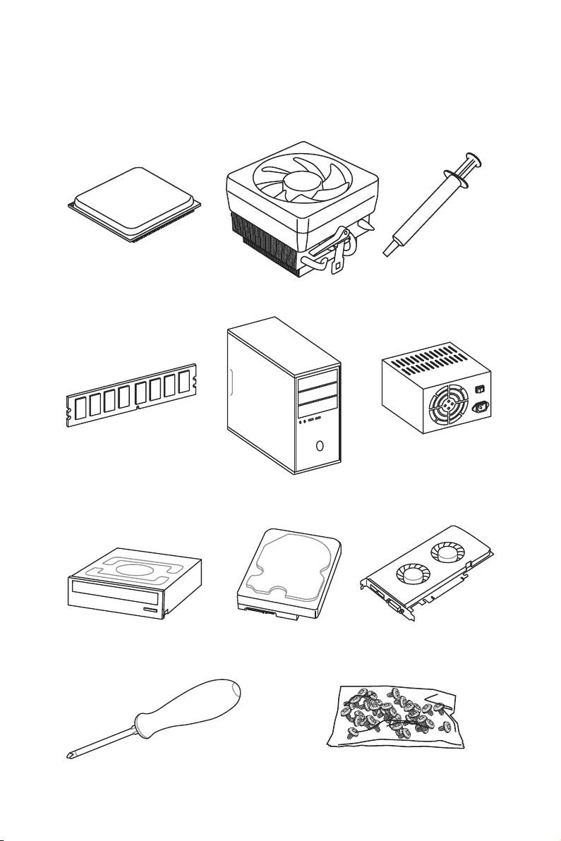
Quick Start
DDR4 Memory
Graphics Card
SATA Hard Disk Drive
SATA DVD Drive
A Package of Screws
Phillips Screwdriver
Chassis
Power Supply Unit
CPU Fan
Thermal Paste
Quick Start
Preparing Tools and Components
AMD® AM4 CPU
4Quick Start
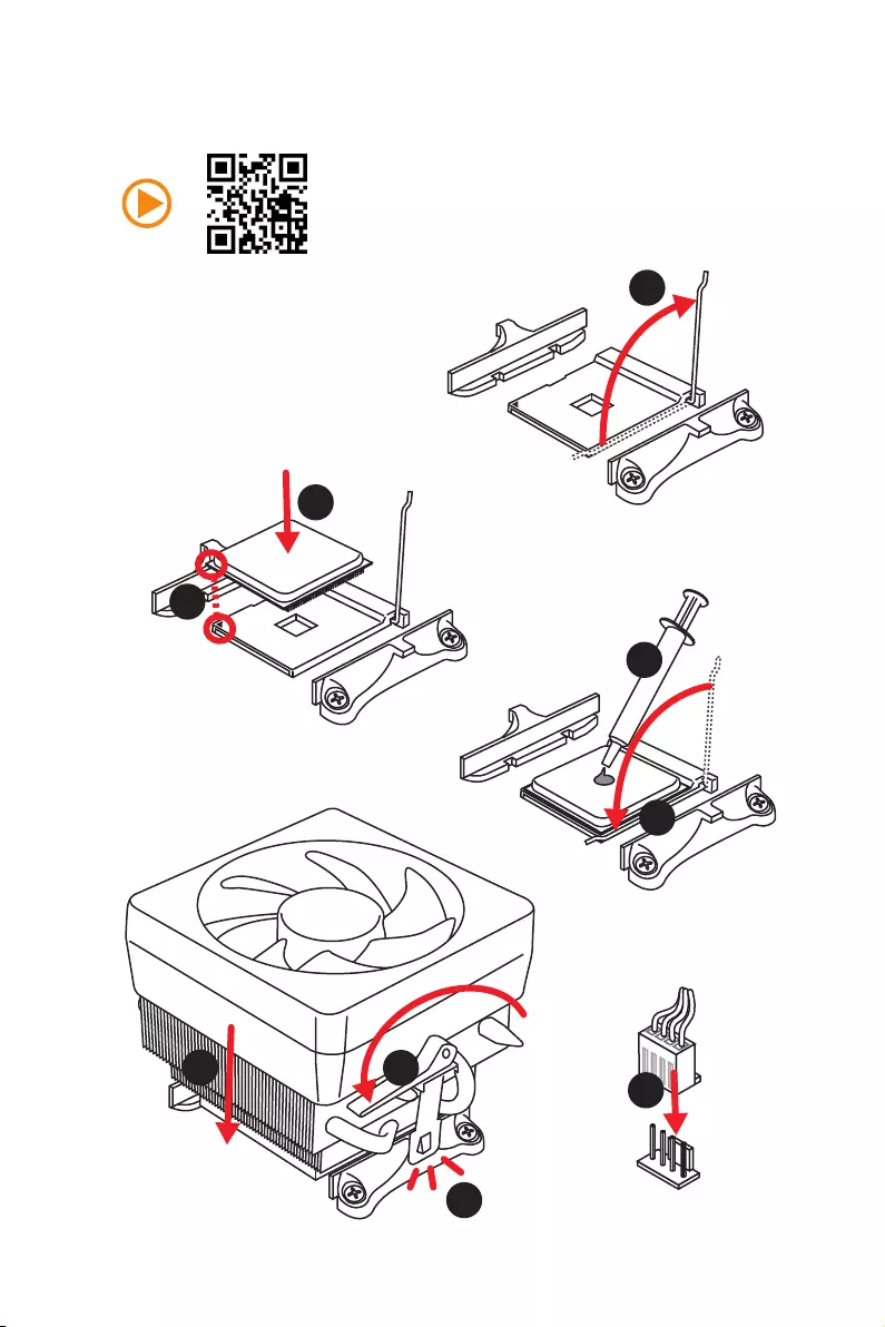
Installing a Processor
1
2
3
6
4
5
7
8
9
5
Quick Start
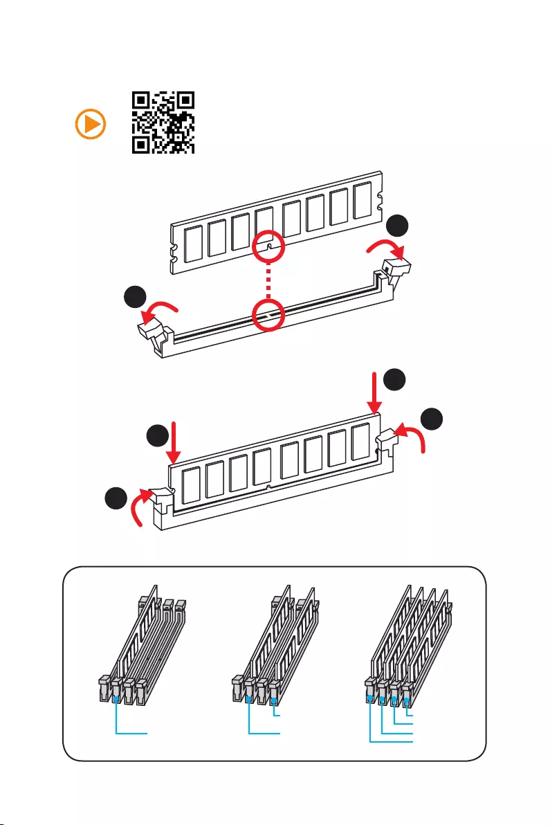
Installing DDR4 memory
DIMMB2 DIMMB2
DIMMB1
DIMMA2 DIMMA2 DIMMA2
DIMMA1
1
1
2
2
3
3
6Quick Start
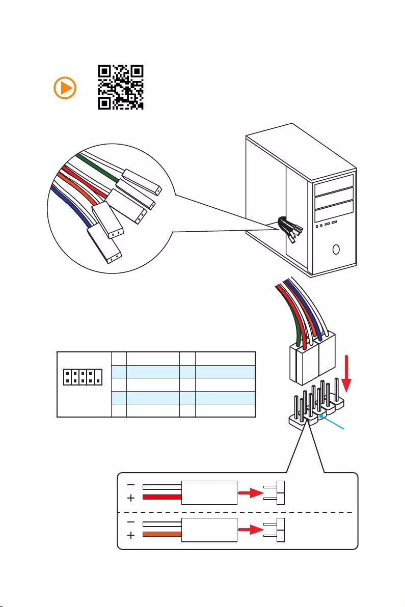
Connecting the Front Panel Header
1
2 10
9
JFP1
1 HDD LED + 2 Power LED +
3 HDD LED — 4 Power LED —
5 Reset Switch 6 Power Switch
7 Reset Switch 8 Power Switch
9 Reserved 10 No Pin
RESET SW
POWER SW
POWER LED+
POWER LED-
HDD LED
HDD LED
RESET SW
JFP1
HDD LED HDD LED —
HDD LED +
POWER LED —
POWER LED +
POWER LED
7
Quick Start
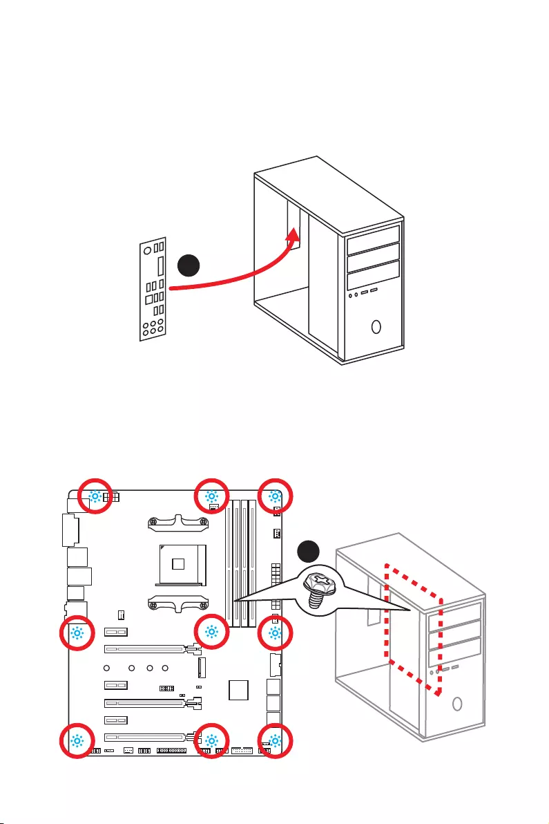
Installing the Motherboard
1
2
8Quick Start
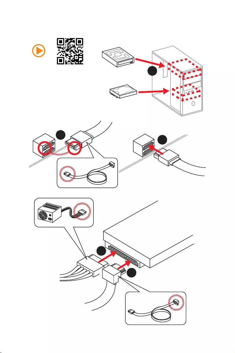
Installing SATA Drives
1
23
4
5
9
Quick Start
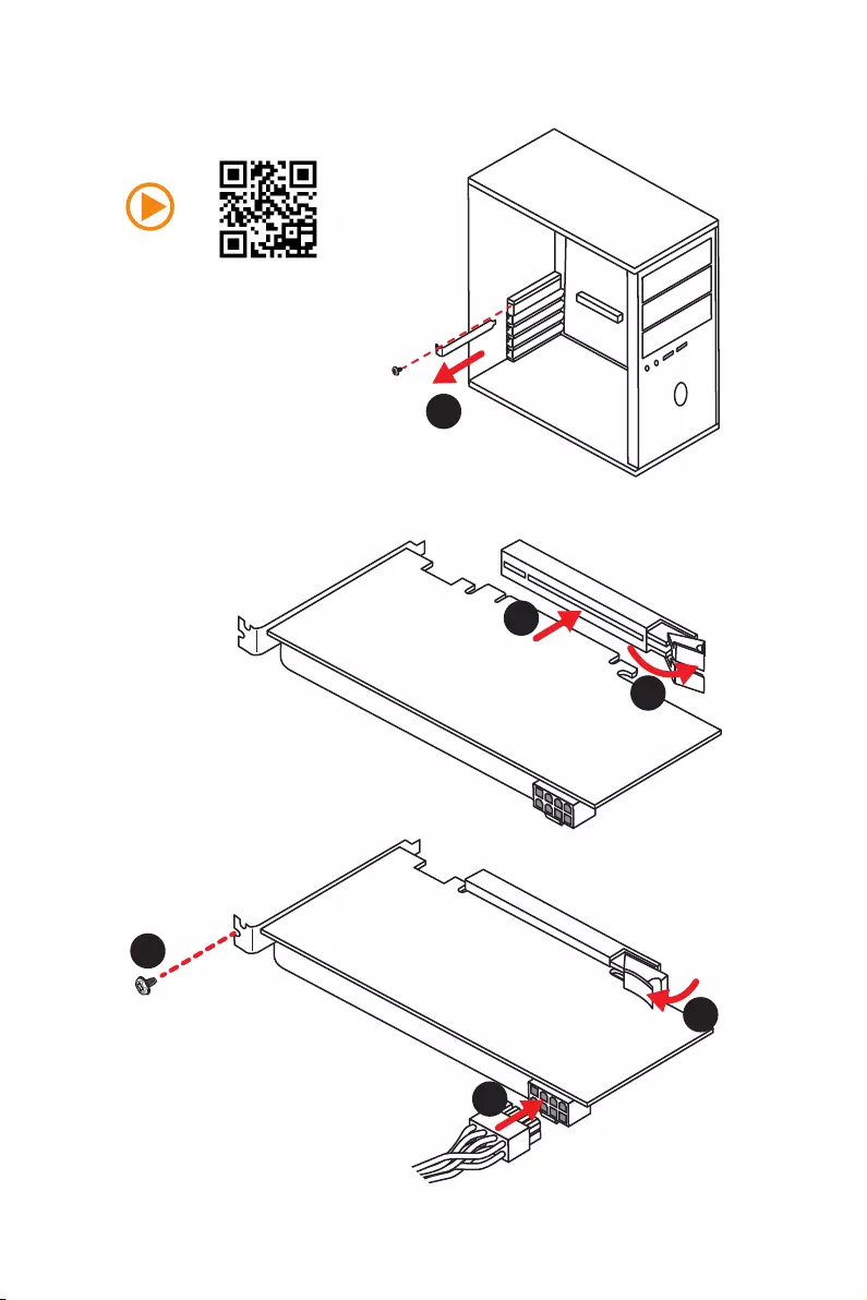
1
Installing a Graphics Card
2
3
4
5
6
10 Quick Start
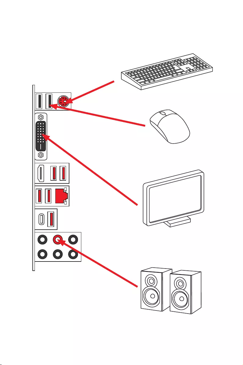
Connecting Peripheral Devices
11
Quick Start
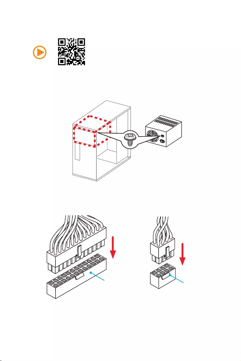
Connecting the Power Connectors
ATX_PWR1 CPU_PWR1
12 Quick Start
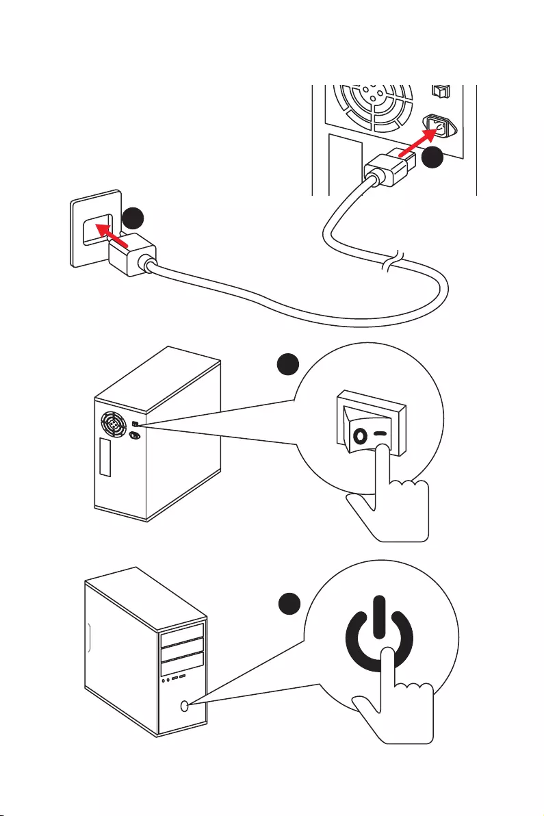
Power On
1
4
2
3

13
Contents
Contents
Unpacking ……………………………………………………………………………………………….. 1
Safety Information ……………………………………………………………………………………. 2
Quick Start ………………………………………………………………………………………………. 3
Preparing Tools and Components ……………………………………………………………….. 3
Installing a Processor ………………………………………………………………………………… 4
Installing DDR4 memory ……………………………………………………………………………. 5
Connecting the Front Panel Header …………………………………………………………….. 6
Installing the Motherboard …………………………………………………………………………. 7
Installing SATA Drives………………………………………………………………………………… 8
Installing a Graphics Card ………………………………………………………………………….. 9
Connecting Peripheral Devices …………………………………………………………………. 10
Connecting the Power Connectors …………………………………………………………….. 11
Power On………………………………………………………………………………………………… 12
Specifications …………………………………………………………………………………………. 15
Block Diagram ………………………………………………………………………………………. 20
Rear I/O Panel ……………………………………………………………………………………….. 21
LAN Port LED Status Table……………………………………………………………………….. 21
Audio Ports Configuration ………………………………………………………………………… 21
Realtek HD Audio Manager ………………………………………………………………………. 22
Overview of Components ………………………………………………………………………… 24
CPU Socket …………………………………………………………………………………………….. 26
DIMM Slots ……………………………………………………………………………………………… 27
PCI_E1~6: PCIe Expansion Slots ……………………………………………………………….. 28
M2_1: M.2 Slot (Key M) …………………………………………………………………………….. 31
SATA1~6: SATA 6Gb/s Connectors …………………………………………………………….. 32
CPU_PWR1, ATX_PWR1: Power Connectors ………………………………………………. 33
JUSB1~2: USB 2.0 Connectors ………………………………………………………………….. 34
JUSB3~4: USB 3.1 Gen1 Connectors …………………………………………………………. 34
CPU_FAN1, PUMP_FAN1, SYS_FAN1~4: Fan Connectors …………………………….. 35
JAUD1: Front Audio Connector …………………………………………………………………. 36
JCI1: Chassis Intrusion Connector …………………………………………………………….. 36
JFP1, JFP2: Front Panel Connectors …………………………………………………………. 37
JTPM1: TPM Module Connector ………………………………………………………………… 37
JBAT1: Clear CMOS (Reset BIOS) Jumper ………………………………………………….. 38
JLPT1: Parallel Port Connector ………………………………………………………………… 38
JCOM1: Serial Port Connector ………………………………………………………………….. 39

14 Contents
JLED1: RGB LED connector ……………………………………………………………………… 39
Onboard LEDs ………………………………………………………………………………………… 40
EZ Debug LED …………………………………………………………………………………………. 40
DIMM LEDs …………………………………………………………………………………………….. 40
GPU LED ………………………………………………………………………………………………… 40
PCIe x16 slot LEDs…………………………………………………………………………………… 40
BIOS Setup …………………………………………………………………………………………….. 41
Entering BIOS Setup ………………………………………………………………………………… 41
Resetting BIOS ………………………………………………………………………………………… 42
Updating BIOS …………………………………………………………………………………………. 42
Advanced Mode ………………………………………………………………………………………. 45
SETTINGS ……………………………………………………………………………………………….. 46
Advanced ………………………………………………………………………………………………… 46
Boot ……………………………………………………………………………………………………….. 51
Security ………………………………………………………………………………………………….. 52
Save & Exit ……………………………………………………………………………………………… 53
OC ………………………………………………………………………………………………………….. 55
M-FLASH ……………………………………………………………………………………………….. 58
OC PROFILE ……………………………………………………………………………………………. 59
HARDWARE MONITOR ……………………………………………………………………………… 60
Software Description ………………………………………………………………………………. 61
Installing Windows® 7 64-bit/ Windows®10 64-bit ……………………………………….. 61
Installing Drivers …………………………………………………………………………………….. 61
Installing Utilities ……………………………………………………………………………………. 61
LIVE UPDATE 6 ………………………………………………………………………………………… 62
COMMAND CENTER ………………………………………………………………………………… 64
GAMING APP …………………………………………………………………………………………… 68
RAMDISK………………………………………………………………………………………………… 73
X-BOOST ………………………………………………………………………………………………… 74
MSI SMART TOOL ……………………………………………………………………………………. 76
GAMING LAN MANAGER ………………………………………………………………………….. 78
DRAGON EYE ………………………………………………………………………………………….. 80
SteelSeries Engine 3 ……………………………………………………………………………….. 81
CPU-Z…………………………………………………………………………………………………….. 83
Troubleshooting …………………………………………………………………………………….. 84
Regulatory Notices …………………………………………………………………………………. 85

15
Specifications
Specifications
CPU Supports AMD® RYZEN series processors and 7th Gen
A-series/ Athlon™ processors for Socket AM4
Chipset AMD® X370 Chipset
Memory
y4x DDR4 memory slots, support up to 64GB
Supports DDR4 1866/ 2133/ 2400/ 2667(OC)/ 2933(OC)/
3200(OC)+ Mhz *
yDual channel memory architecture
ySupports non-ECC UDIMM memory
ySupports ECC UDIMM memory (non-ECC mode)
* 7th Gen A-series/ Athlon ™ processors support a maximum of 2400 MHz.
Please refer www.msi.com for more information on compatible memory
Expansion Slots
y2x PCIe 3.0 x16 slots (PCIE_2, PCIE_4)
RYZEN series processors support x16/x0, x8/x8 mode
7th Gen A-series/ Athlon™ processors support x8/x0
mode
y1x PCIe 2.0 x16 slot (PCIE_6, supports x4 mode)*
y3x PCIe 2.0 x1 slots
* PCI_E6 slot will be PCIe 2.0 x1 when installing device in any PCIe x1 slot.
Onboard Graphics
y1x DVI-D port, supporting a maximum resolution of
1920×1200@60Hz, 1600×1200@60Hz*
y1x HDMI™ 1.4 port, supports a maximum resolution of
2560×1600@60Hz*
* Only support when using a 7th Gen A-series/ Athlon™ processors
Multi-GPU
yRYZEN series processor
Supports 2-Way NVIDIA® SLI™ Technology
Supports 3-Way AMD® CrossFire™ Technology
y7th Gen A-series/ Athlon™ processor
Supports 2-Way AMD® CrossFire™ Technology
Storage
AMD® X370 Chipset
y6x SATA 6Gb/s ports
y1x M.2 port (Key M)
Supports PCIe 3.0 x4 (RYZEN series processor) or PCIe
3.0 x2 (7th Gen A-series/ Athlon™ processors) and SATA
6Gb/s 2242/ 2260 /2280/ 22110 storage devices
ySupports RAID 0, RAID 1 and RAID 10
Continued on next page

16 Specifications
Continued from previous page
USB
yASMedia® ASM2142 Chipset
1x USB 3.1 Gen2 (SuperSpeed USB 10Gbps) Type-C port
on the back panel
1x USB 3.1 Gen2 (SuperSpeed USB 10Gbps) Type-A port
on the back panel
yAMD® X370 Chipset
4x USB 3.1 Gen1 (SuperSpeed USB) ports available
through the internal USB connectors
6x USB 2.0 (High-speed USB) ports (2 Type-A ports on
the back panel, 4 ports available through the internal
USB connectors)
yAMD® CPU
4x USB 3.1 Gen1 (SuperSpeed USB) Type-A ports on the
back panel
Audio yRealtek® ALC892 Codec
y7.1-Channel High Definition Audio
LAN y1x Realtek® 8111H Gigabit LAN controller
Back Panel
Connectors
y1x PS/2 keyboard/ mouse combo port
y2x USB 2.0 Type-A ports
y1x DVI-D port
y1x HDMI™ 1.4 port
y1x LAN (RJ45) port
y4x USB 3.1 Gen1 Type-A ports
y1x USB 3.1 Gen2 Type-A port
y1x USB 3.1 Gen2 Type-C port
y6x audio jacks
Continued on next page

17
Specifications
Continued from previous page
Internal Connectors
y1x 24-pin ATX 12V power connector
y1x 8-pin ATX 12V power connector
y6x SATA 6Gb/s connectors
y2x USB 2.0 connectors (support additional 4 USB 2.0 ports)
y2x USB 3.1 Gen1 connectors (support additional 4 USB 3.1
Gen1 ports)
y1x 4-pin CPU fan connector
y1x 4-pin PUMP fan connector (supports up to 2A)
y4x 4-pin system fan connectors
y1x RGB LED connector
y1x TPM module connector
y1x Serial port connector
y1x Parallel port connector
y1x Front panel audio connector
y2x System panel connectors
y1x Chassis Intrusion connector
y1x Clear CMOS jumper
I/O Controller NUVOTON NCT6795D Controller Chip
Hardware Monitor
yCPU/System temperature detection
yCPU/System fan speed detection
yCPU/System fan speed control
Form Factor yATX Form Factor
y12 in. x 9.6 in. (30.4 cm x 24.3 cm)
BIOS Features
y1x 128 Mb flash
yUEFI AMI BIOS
yACPI 5.0, PnP 1.0a, SM BIOS 2.8
yMulti-language
Continued on next page

18 Specifications
Continued from previous page
Software
yDrivers
yCOMMAND CENTER
yLIVE UPDATE 6
ySUPER CHARGER
yGAMING APP
yRAMDISK
yX-BOOST
yMSI SMART TOOL
yGAMING LAN MANAGER
yDRAGON EYE
yNorton™ Internet Security Solution
yGoogle Chrome™, Google Toolbar, Google Drive
ySteelSeries Engine 3
yCPU-Z MSI GAMING
Continued on next page

19
Specifications
Continued from previous page
Special Features
yVR Boost
yAudio Boost
yGAMING LAN with Gaming LAN Manager
yTurbo M.2
yPump Fan
ySmart Fan Control
yGaming DNA with bottom LED
yMystic light SYNC
yEZ debug LED
yPCI-E Steel Armor
yM.2 Steel Armor
yUSB with type A+C
yMulti GPU – SLI Technology
yMulti GPU – CrossFire Technology
yDDR4 Boost
yGAME Boost
yLightning USB
yMilitary Class 4
y7000+ Quality Test
yGAMING HOTKEY
yGAMING MOUSE Control
yClick BIOS 5
yAMD FreeSync™ Ready
yAMD OverDrive™ Ready
yGAMING Certified
ySteelSeries Certified
yWTFast GPN*
2-Month Premium License
Multi-Server Network Optimization
Advanced Lag Spike & Disconnect Reduction
* This offer is valid for a limited period only, for more information please visit
www.msi.com
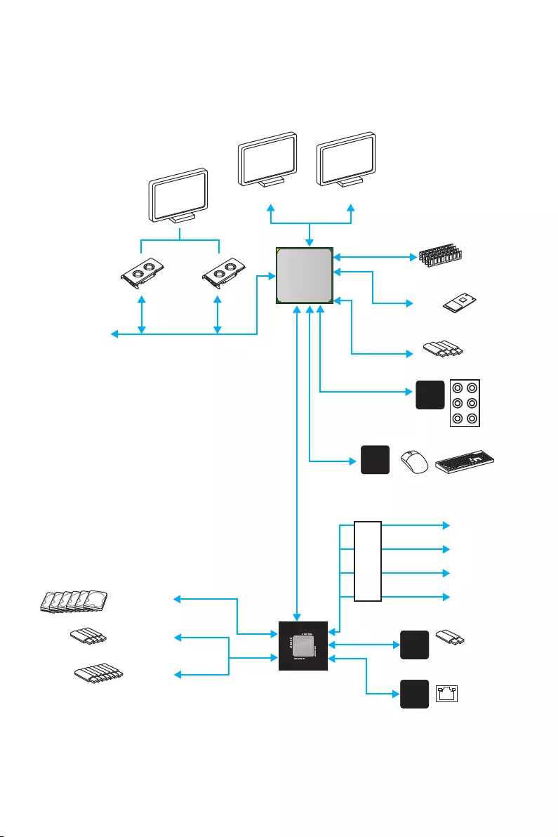
20 Block Diagram
Block Diagram
2 x USB 3.1 Gen2
2 Channel DDR4 Memory
4 x USB 3.1 Gen1
1 x M.2
6 x USB 2.0
P/S2 Mouse / Keyboard
Audio Jacks
PCIex4
X370
NV6795
Super I/O
Realtek
ALC892
ASMEDIA
ASM2142
PCI Express Bus
HDMI DVI-D
PCIe x1 slot
PCIe x1 slot
6 x SATA 6Gb/s
4 x USB 3.1 Gen1
PCIe x16 slot
(support x4 mode)
CPU
PCIe x1 slot
Realtek
RTL8111H
Switch
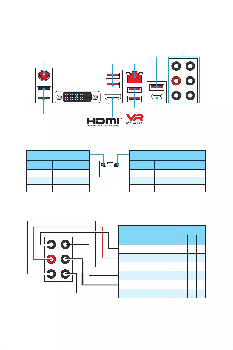
21
Rear I/O Panel
USB 3.1 Gen2 Type-C
Link/ Activity LED
Status Description
Off No link
Yellow Linked
Blinking Data activity
Speed LED
Status Description
Off 10 Mbps connection
Green 100 Mbps connection
Orange 1 Gbps connection
LAN Port LED Status Table
Audio Ports Configuration
Rear I/O Panel
PS/2 LAN
USB 2.0
Audio Ports
DVI-D
USB 3.1 Gen1
USB 3.1 Gen1
USB 3.1 Gen2
Audio Ports Channel
2468
Line-In
Line-Out/ Front Speaker Out ●●●●
Mic In
Rear Speaker Out ●●●
Center/ Subwoofer Out ● ●
Side Speaker Out ●
(●: connected, Blank: empty)
22 Rear I/O Panel
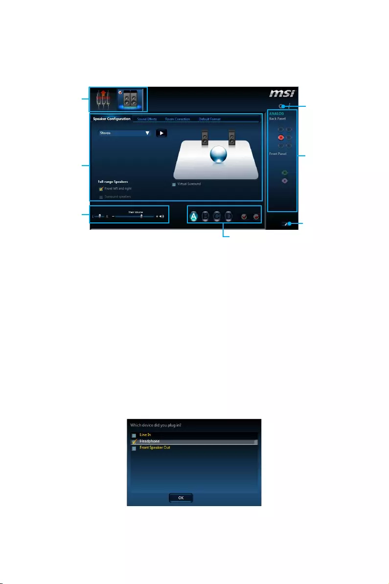
Realtek HD Audio Manager
After installing the Realtek HD Audio driver, the Realtek HD Audio Manager icon will
appear in the system tray. Double click on the icon to launch.
Jack Status
Device
Selection
Connector
Strings
Profiles
Main Volume
Application
Enhancement
Advanced
Settings
yDevice Selection — allows you to select a audio output source to change the related
options. The check sign indicates the devices as default.
yApplication Enhancement — the array of options will provide you a complete
guidance of anticipated sound effect for both output and input device.
yMain Volume — controls the volume or balance the right/left side of the speakers
that you plugged in front or rear panel by adjust the bar.
yProfiles — toggles between profiles.
yAdvanced Settings — provides the mechanism to deal with 2 independent audio
streams.
yJack Status — depicts all render and capture devices currently connected with your
computer.
yConnector Settings — configures the connection settings.
Auto popup dialog
When you plug into a device at an audio jack, a dialogue window will pop up asking you
which device is current connected.
Each jack corresponds to its default setting as shown on the next page.
23
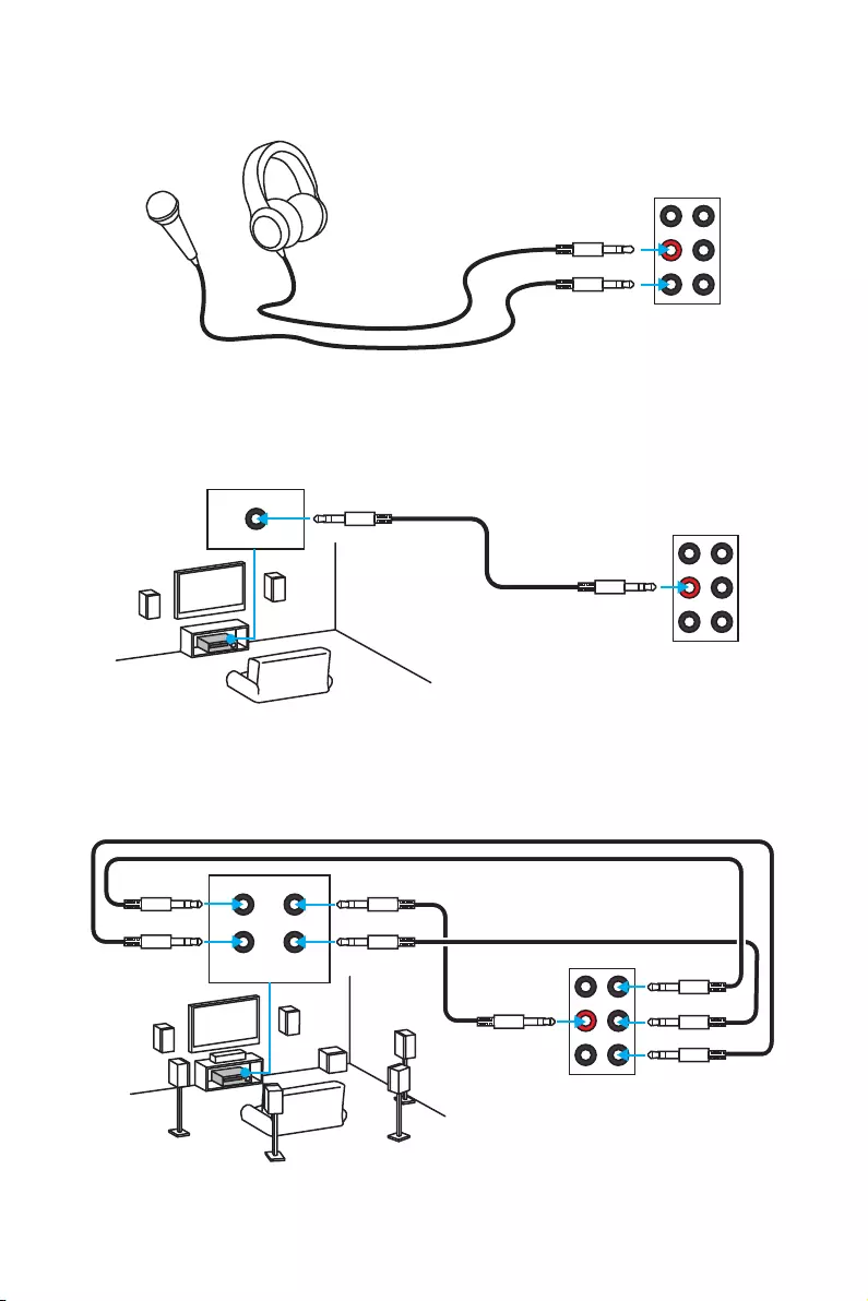
Rear I/O Panel
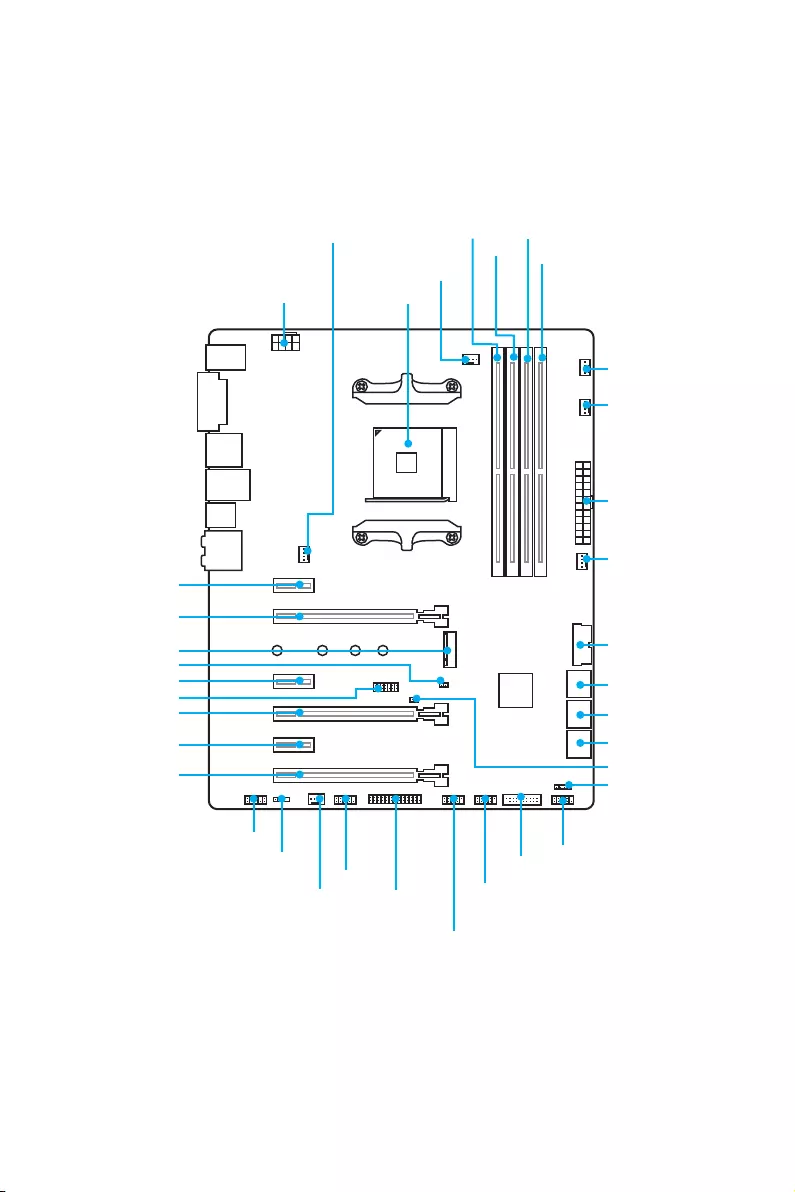
Audio jacks to headphone and microphone diagram
Audio jacks to stereo speakers diagram
Audio jacks to 7.1-channel speakers diagram
AUDIO INPUT
AUDIO INPUT
Rear Front
Side Center/
Subwoofer
24 Overview of Components
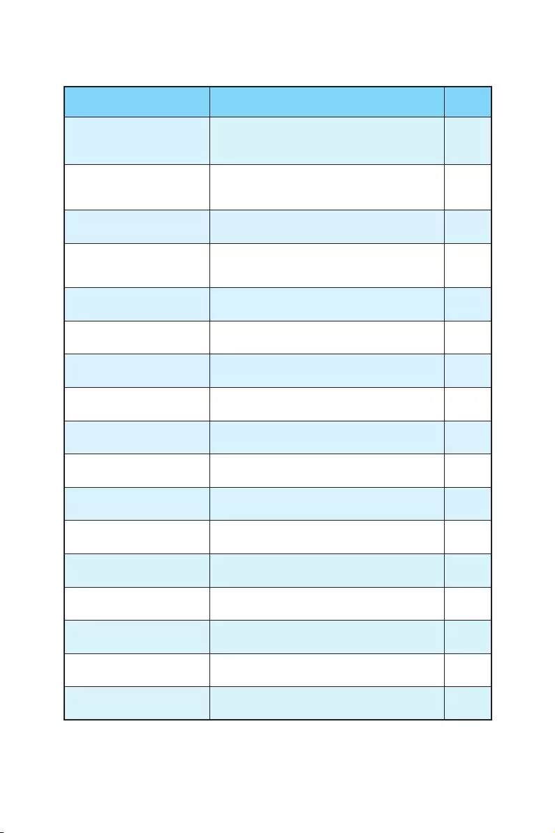
Overview of Components
SATA▼3▲4
SATA▼1▲2
SATA▼5▲6
CPU_FAN1
PUMP_FAN1
PCI_E1
PCI_E2
PCI_E3
PCI_E4
PCI_E5
PCI_E6
JTPM1
CPU Socket
CPU_PWR1
JBAT1
M2_1
DIMMA1
SYS_FAN1
SYS_FAN4
DIMMA2
DIMMB1
DIMMB2
JUSB1
JUSB3
JCOM1
JUSB2
JFP2
JFP1
JAUD1
JLED1
SYS_FAN2 JLPT1
ATX_PWR1
SYS_FAN3
JUSB4
JCI1
25
Overview of Components
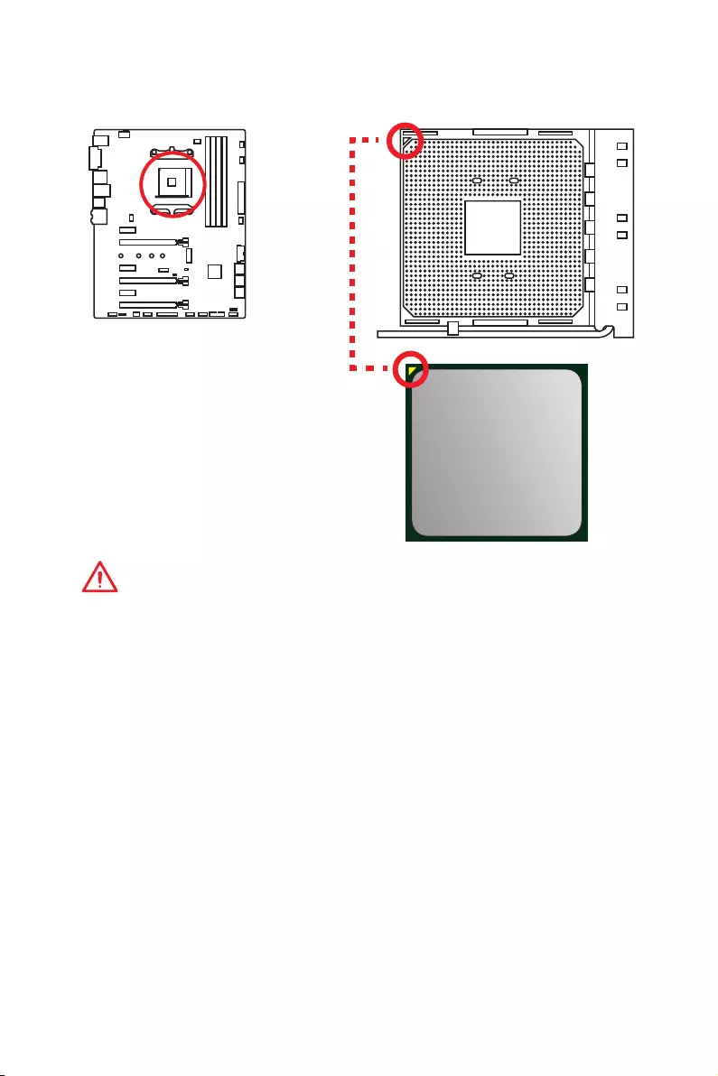
Component Contents
Port Name Port Type Page
CPU_FAN1, PUMP_FAN1,
SYS_FAN1~4 Fan Connectors 35
CPU_PWR1, ATX_PWR1 Power Connectors 33
CPU Socket AM4 CPU Socket 26
DIMMA1, DIMMA2,
DIMMB1, DIMMB2 DIMM Slots 27
JAUD1 Front Audio Connector 36
JBAT1 Clear CMOS (Reset BIOS) Jumper 38
JCI1 Chassis Intrusion Connector 36
JCOM1 Serial Port Connector 39
JFP1, JFP2 Front Panel Connectors 37
JLED1 RGB LED connector 39
JLPT1 Parallel Port Connector 38
JTPM1 TPM Module Connector 37
JUSB1~2 USB 2.0 Connectors 34
JUSB3~4 USB 3.1 Gen1 Connectors 34
M2_1 M.2 Slot (Key M) 31
PCI_E1~6 PCIe Expansion Slots 28
SATA1~6 SATA 6Gb/s Connectors 32
26 Overview of Components
CPU Socket
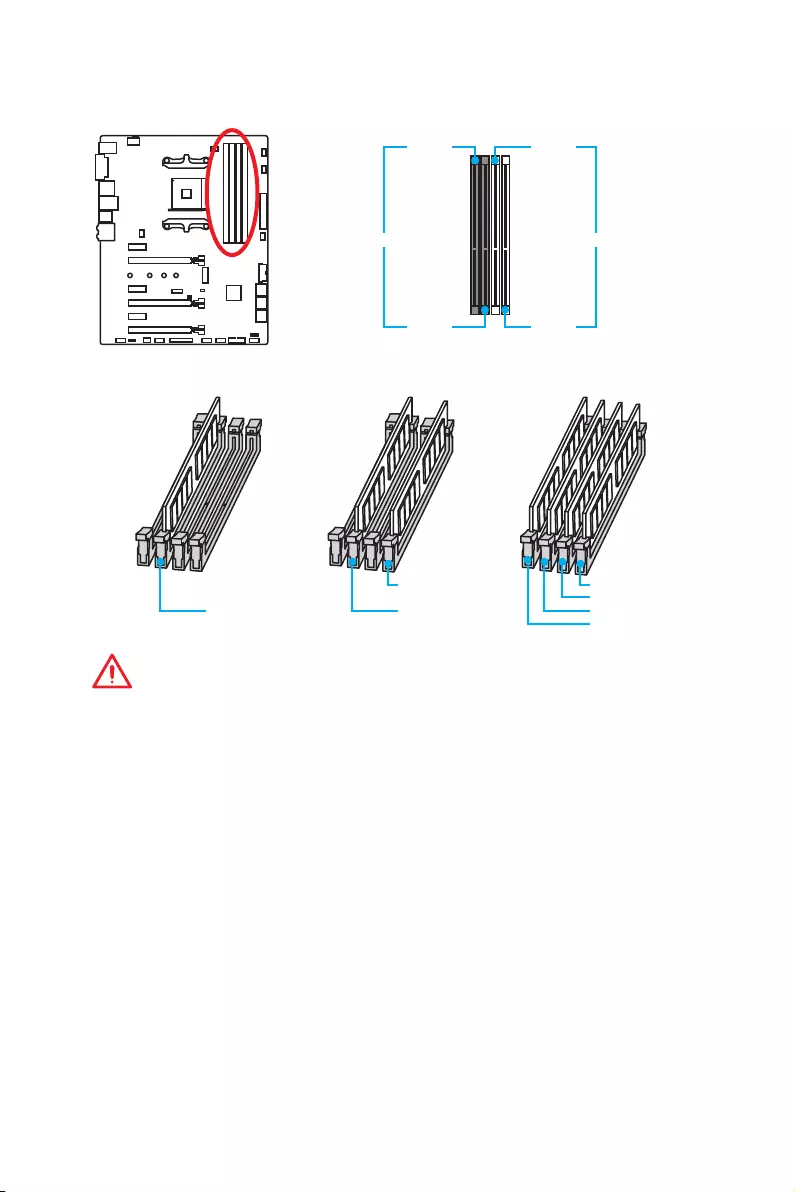
Introduction to the AM4 CPU
The surface of the AM4 CPU has a
yellow triangle to assist in correctly
lining up the CPU for motherboard
placement. The yellow triangle is
the Pin 1 indicator.
Important
y
When changing the processor, the system configuration could be cleared and reset
BIOS to default values, due to the AM4 processor’s architecture.
y
Always unplug the power cord from the power outlet before installing or removing
the CPU.
y
When installing a CPU, always remember to install a CPU heatsink. A CPU heatsink
is necessary to prevent overheating and maintain system stability.
y
Confirm that the CPU heatsink has formed a tight seal with the CPU before booting
your system.
y
Overheating can seriously damage the CPU and motherboard. Always make sure
the cooling fans work properly to protect the CPU from overheating. Be sure to
apply an even layer of thermal paste (or thermal tape) between the CPU and the
heatsink to enhance heat dissipation.
y
If you purchased a separate CPU and heatsink/ cooler, Please refer to the
documentation in the heatsink/ cooler package for more details about installation.
y
This motherboard is designed to support overclocking. Before attempting to
overclock, please make sure that all other system components can tolerate
overclocking. Any attempt to operate beyond product specifications is not
recommended. MSI
®
does not guarantee the damages or risks caused by
inadequate operation beyond product specifications.
27
Overview of Components
DIMM Slots
DIMMA1 DIMMB1
Channel A Channel B
DIMMA2 DIMMB2
Memory module installation recommendation
DIMMB2 DIMMB2
DIMMB1
DIMMA2 DIMMA2 DIMMA2
DIMMA1
Important
y
Always insert memory modules in the DIMMA2 slot first.
y
Due to chipset resource usage, the available capacity of memory will be a little less
than the amount of installed.
y
Based on the processor specification, the Memory DIMM voltage below 1.35V is
suggested to protect the processor.
y
Some memory modules may operate at a lower frequency than the marked value
when overclocking due to the memory frequency operates dependent on its
Serial Presence Detect (SPD). Go to BIOS and find the DRAM Frequency to set the
memory frequency if you want to operate the memory at the marked or at a higher
frequency.
y
It is recommended to use a more efficient memory cooling system for full DIMMs
installation or overclocking.
y
The stability and compatibility of installed memory module depend on installed CPU
and devices when overclocking.
y
Due to AM4 CPU/memory controller official specification limitation, the frequency of
memory modules may operate lower than the marked value under the default state.
Please refer www.msi.com for more information on compatible memory.
28 Overview of Components
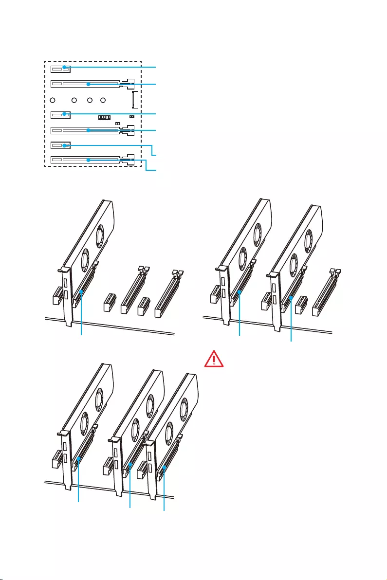
PCI_E1~6: PCIe Expansion Slots
Multiple graphics cards installation recommendation (RYZEN series
processors)
x16 x8
x8
x8
x8 x4
Important
y
If you install a large and heavy
graphics card, you need to use a tool
such as MSI Gaming Series Graphics
Card Bolster to support its weight to
prevent deformation of the slot.
y
For a single PCIe x16 expansion
card installation with optimum
performance, using the PCI_E2 slot
is recommended.
y
When adding or removing expansion
cards, always turn off the power
supply and unplug the power
supply power cable from the power
outlet. Read the expansion card’s
documentation to check for any
necessary additional hardware or
software changes.
PCI_E4: PCIe 3.0 x8 (RYZEN series processors)
Unavailable for 7th Gen A-series/ Athlon™ processors
PCI_E1: PCIe 2.0 x1
PCI_E3: PCIe 2.0 x1
PCI_E5: PCIe 2.0 x1
PCI_E6: PCIe 2.0 x4
PCI_E2: PCIe 3.0 x16 (RYZEN series processors)
PCIe 3.0 x8 (7th Gen A-series/ Athlon™ processors)
29
Overview of Components
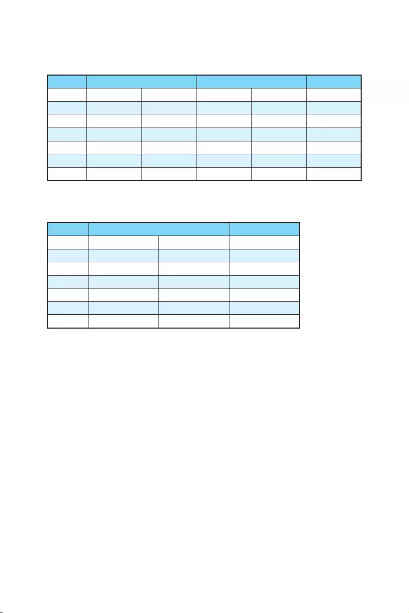
PCIe bandwidth table
For RYZEN series processors
Slot Single 2-Way 3-Way
PCI_E1 ─Gen 2.0 x 1 ─Gen 2.0 x 1 ─
PCI_E2 Gen 3.0 x 16* Gen 3.0 x 16* Gen 3.0 x 8* Gen 3.0 x 8* Gen 3.0 x 8*
PCI_E3 ─Gen 2.0 x 1 ─Gen 2.0 x 1 ─
PCI_E4 ─ ─ Gen 3.0 x 8* Gen 3.0 x 8* Gen 3.0 x 8*
PCI_E5 ─Gen 2.0 x 1 ─Gen 2.0 x 1 ─
PCI_E6 Gen 2.0 x 4 Gen 2.0 x 1 Gen 2.0 x 4 Gen 2.0 x 1 Gen 2.0 x 4*
M2_1 Gen 3.0 x 4 Gen 3.0 x 4 Gen 3.0 x 4 Gen 3.0 x 4 Gen 3.0 x 4
(─: empty, *: graphics card)
For 7th Gen A-series/ Athlon™ processors
Slot Single 2-Way
PCI_E1 ─Gen 2.0 x 1 ─
PCI_E2 Gen 3.0 x 8* Gen 3.0 x 8* Gen 3.0 x 8*
PCI_E3 ─Gen 2.0 x 1 ─
PCI_E4 ───
PCI_E5 ─Gen 2.0 x 1 ─
PCI_E6 Gen 2.0 x 4 Gen 2.0 x 1 Gen 2.0 x 4*
M2_1 Gen 3.0 x 2 Gen 3.0 x 2 Gen 3.0 x 2
(─: empty, *: graphics card)
30 Overview of Components
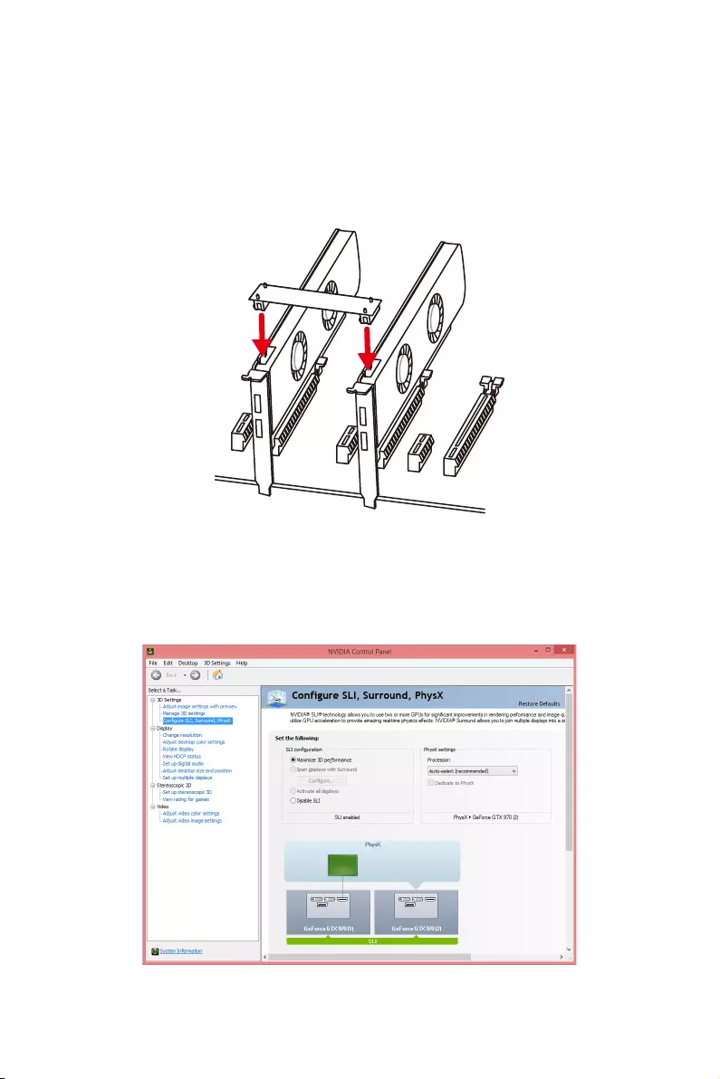
Installing SLI graphics cards
For power supply recommendations for SLI configurations, please refer to the user
guide of your graphics card to make sure you meet all the system requirements.
To install SLI graphics cards:
1. Turn off your computer and disconnect the power cord, install two graphics cards
into the PCI_E2 and PCI_E4 slots.
2. Connect the two cards together using the SLI Bridge Connector.
3. Connect all PCIe power connectors of the graphics cards.
4. Reconnect the power cord, power up the computer and install the drivers and
software included in your graphics card package.
5. Right-click the Windows desktop and select NVIDIA Control Panel from the menu,
click on Configure SLI, Surround, PhysX in the left task pane and select Maximize
3D performance in the SLI configuration menu, and then click Apply.
31
Overview of Components
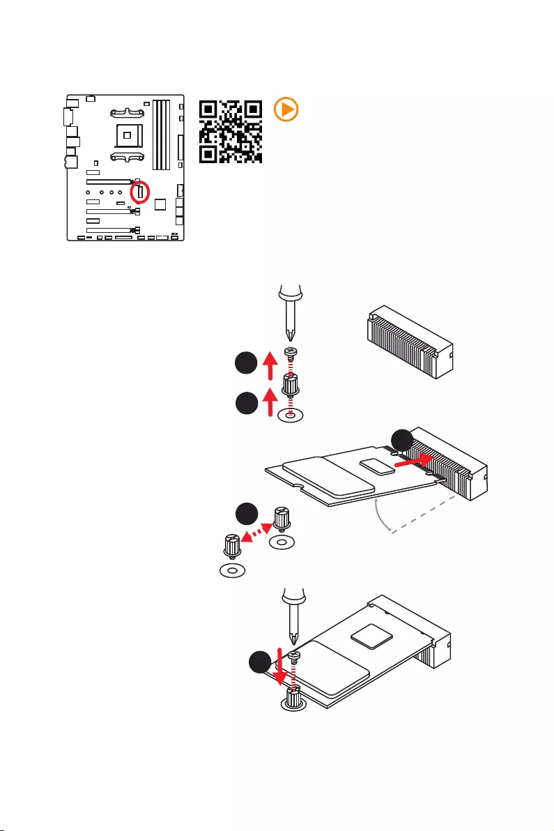
M2_1: M.2 Slot (Key M)
Video Demonstration
Watch the video to learn how to Install M.2
module.
http://youtu.be/JCTFABytrYA
Installing M.2 module
1
2
330°
3. Tighten the base screw
into the hole of the
distance to the M.2 slot
as the length your M.2
module.
4. Insert your M.2 module
into the M.2 slot at a
30-degree angle.
5. Put the screw in the
notch on the trailing edge
of your M.2 module and
tighten it into the base
screw.
1. Remove the screw from
the base screw.
2. Remove the base screw.
4
5
32 Overview of Components
SATA1~6: SATA 6Gb/s Connectors
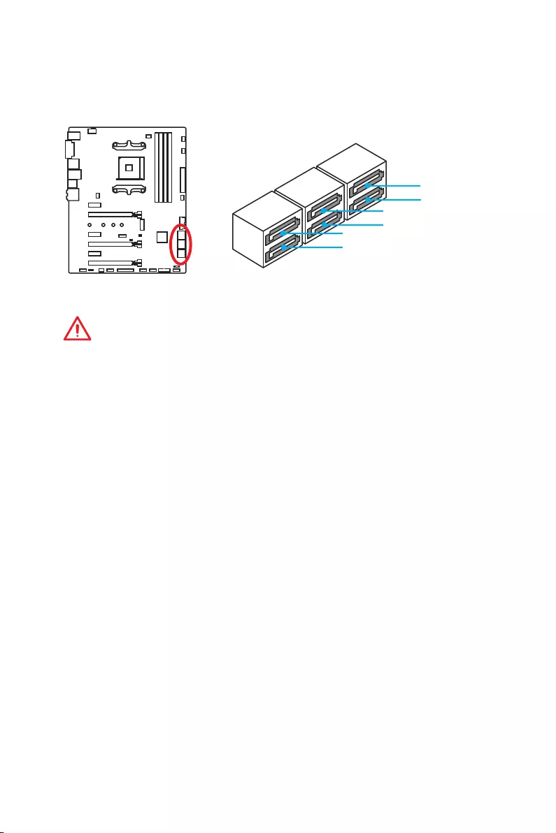
These connectors are SATA 6Gb/s interface ports. Each connector can connect to one
SATA device.
SATA5
SATA1
SATA3
SATA6
SATA2
SATA4
Important
y
Please do not fold the SATA cable at a 90-degree angle. Data loss may result during
transmission otherwise.
y
SATA cables have identical plugs on either sides of the cable. However, it is
recommended that the flat connector be connected to the motherboard for space
saving purposes.
33
Overview of Components
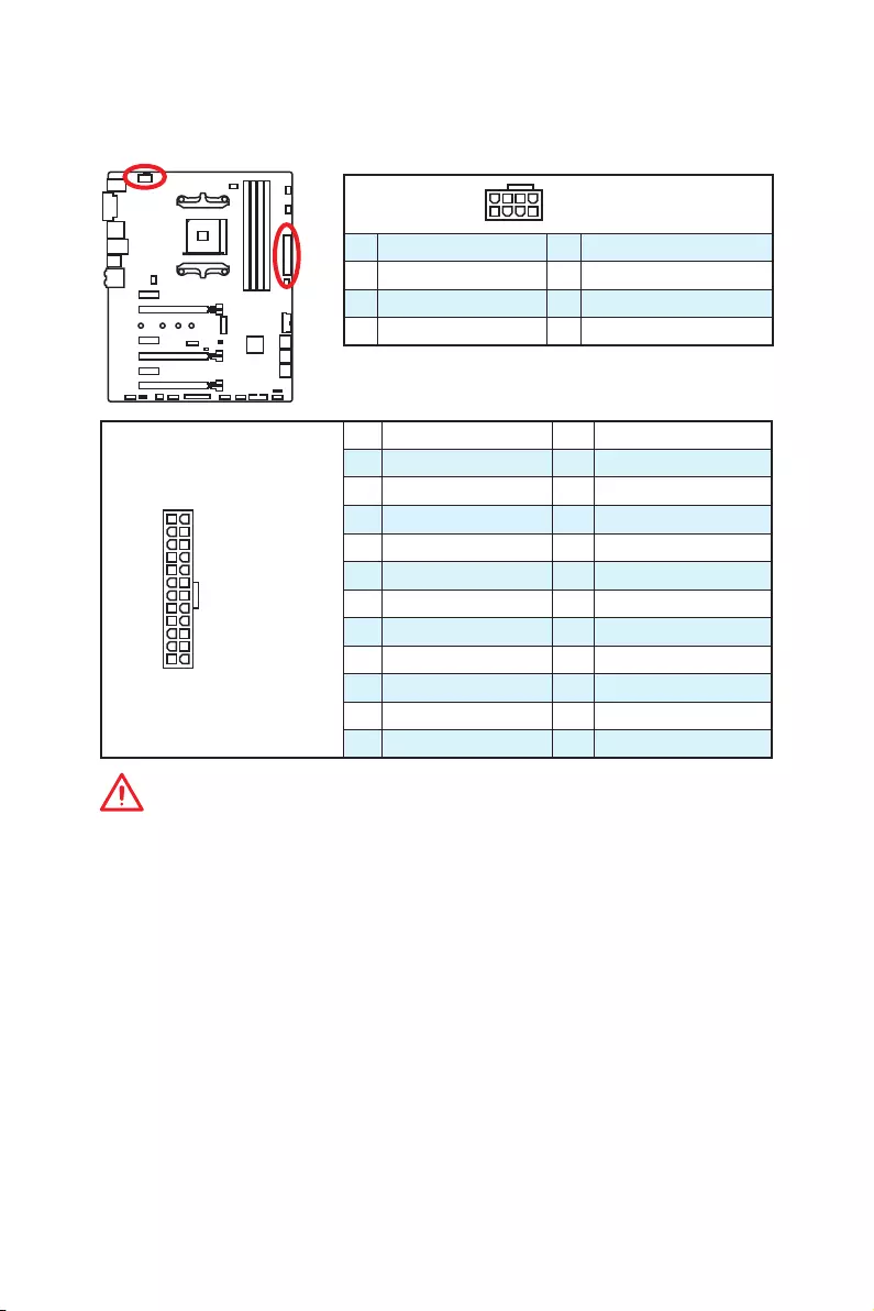
24
131
12
ATX_PWR1
1 +3.3V 13 +3.3V
2 +3.3V 14 -12V
3 Ground 15 Ground
4 +5V 16 PS-ON#
5 Ground 17 Ground
6 +5V 18 Ground
7 Ground 19 Ground
8 PWR OK 20 Res
9 5VSB 21 +5V
10 +12V 22 +5V
11 +12V 23 +5V
12 +3.3V 24 Ground
5
4 1
8CPU_PWR1
1 Ground 5 +12V
2 Ground 6 +12V
3 Ground 7 +12V
4 Ground 8 +12V
Important
Make sure that all the power cables are securely connected to a proper ATX power
supply to ensure stable operation of the motherboard.
CPU_PWR1, ATX_PWR1: Power Connectors
These connectors allow you to connect an ATX power supply.
34 Overview of Components
JUSB1~2: USB 2.0 Connectors
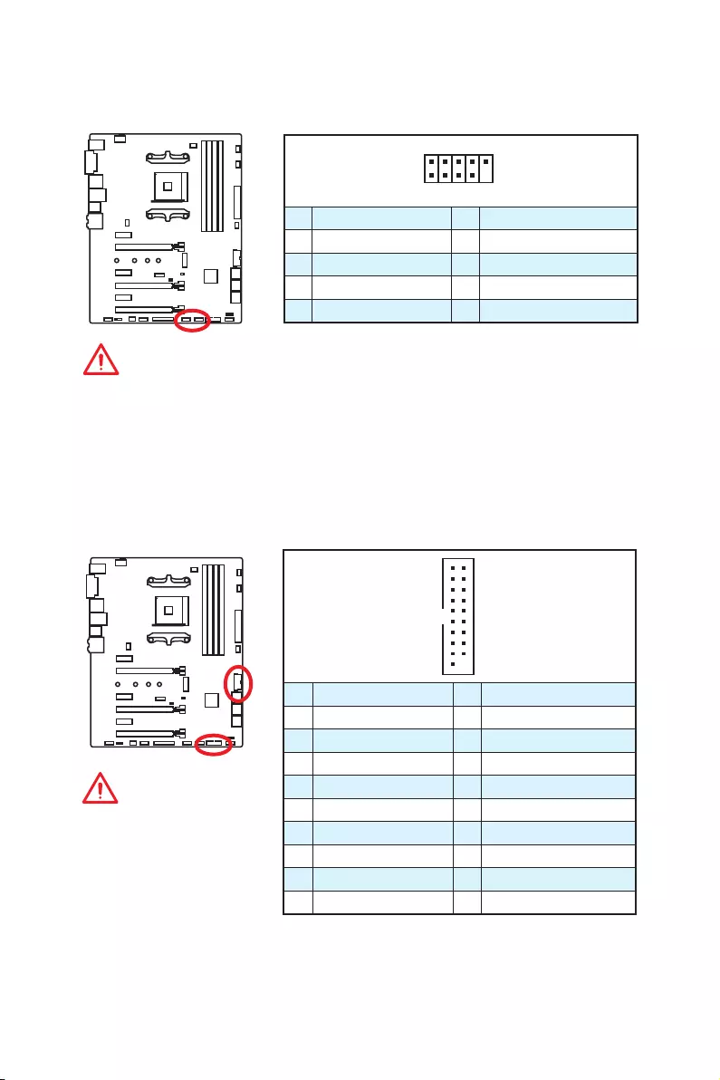
These connectors allow you to connect USB 2.0 ports on the front panel.
1
2 10
9
1VCC 2VCC
3 USB0- 4 USB1-
5 USB0+ 6 USB1+
7 Ground 8 Ground
9 No Pin 10 NC
Important
y
Note that the VCC and Ground pins must be connected correctly to avoid possible
damage.
y
In order to recharge your iPad,iPhone and iPod through USB ports, please install
MSI
®
SUPER CHARGER utility.
JUSB3~4: USB 3.1 Gen1 Connectors
These connectors allow you to connect USB 3.1 Gen1 ports on the front panel.
1
10 11
20
1Power 11 USB2.0+
2 USB3_RX_DN 12 USB2.0-
3 USB3_RX_DP 13 Ground
4 Ground 14 USB3_TX_C_DP
5 USB3_TX_C_DN 15 USB3_TX_C_DN
6 USB3_TX_C_DP 16 Ground
7 Ground 17 USB3_RX_DP
8 USB2.0- 18 USB3_RX_DN
9 USB2.0+ 19 Power
10 NC 20 No Pin
Important
Note that the Power and
Ground pins must be
connected correctly to avoid
possible damage.
35
Overview of Components
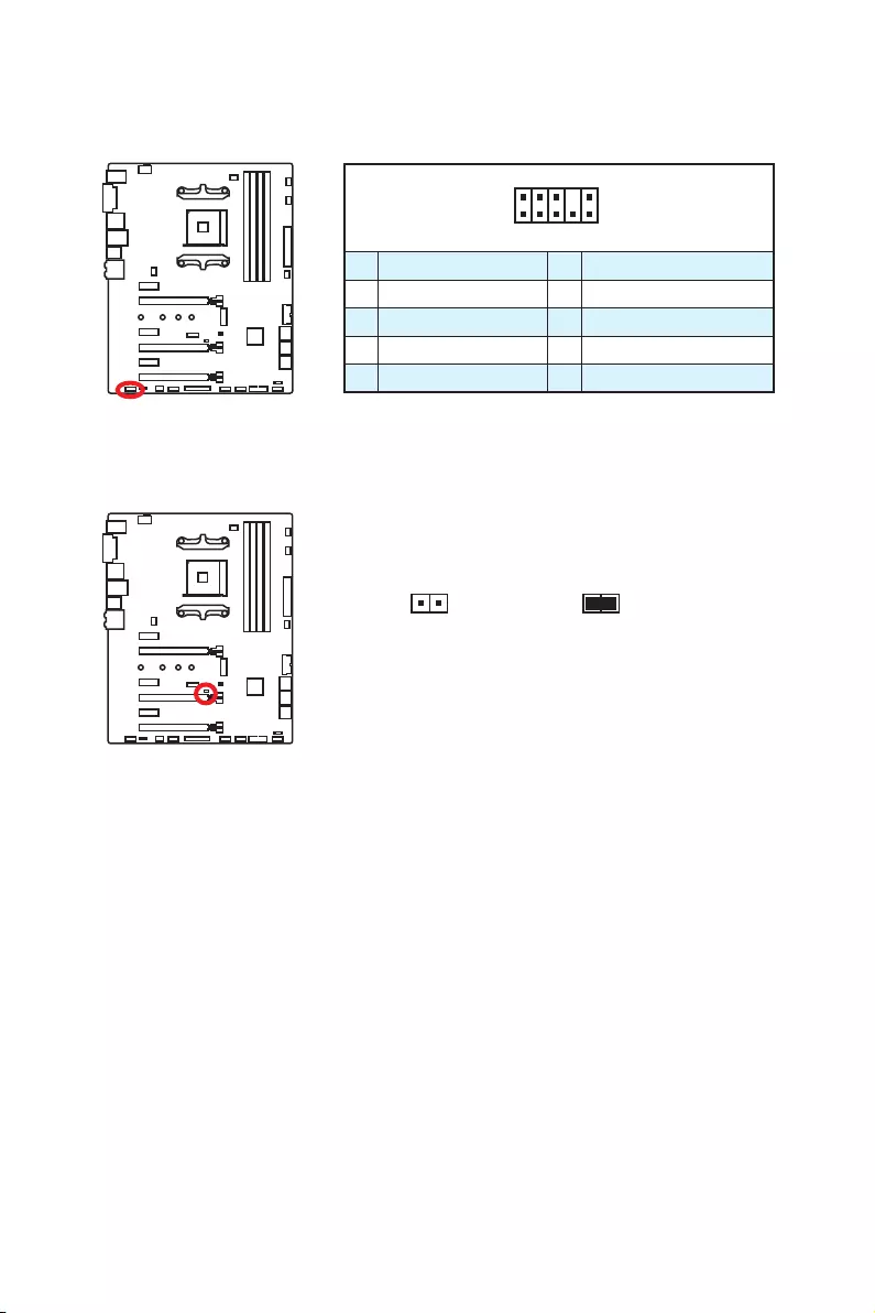
CPU_FAN1, PUMP_FAN1, SYS_FAN1~4: Fan Connectors
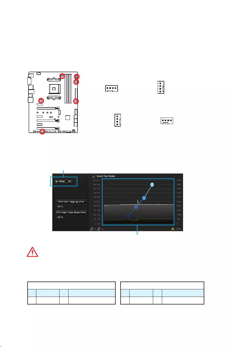
Fan connectors can be classified as PWM (Pulse Width Modulation) Mode or DC Mode.
PWM Mode fan connectors provide constant 12V output and adjust fan speed with
speed control signal. DC Mode fan connectors control fan speed by changing voltage.
When you plug a 3-pin (Non-PWM) fan to a fan connector in PWM mode, the fan speed
will always maintain at 100%, which might create a lot of noise. You can follow the
instruction below to adjust the fan connector to PWM or DC Mode.
PWM Mode pin definition
1 Ground 2 +12V
3 Sense 4 Speed Control Signal
DC Mode pin definition
1 Ground 2 Voltage Control
3 Sense 4 NC
Default PWM Mode fan connectors
Default DC Mode fan connectors
Switching fan mode and adjusting fan speed
You can switch between PWM mode and DC mode and adjust fan speed in BIOS >
HARDWARE MONITOR.
Select PWM mode or DC mode
Important
Make sure fans are working properly after switching the PWM/ DC mode.
There are gradient points of the fan speed that allow you to adjust
fan speed in relation to CPU temperature.
1
CPU_FAN1
1
SYS_FAN1/ SYS_FAN3/ SYS_FAN4
1
SYS_FAN2
Pin definition of fan connectors
1
PUMP_FAN1
36 Overview of Components
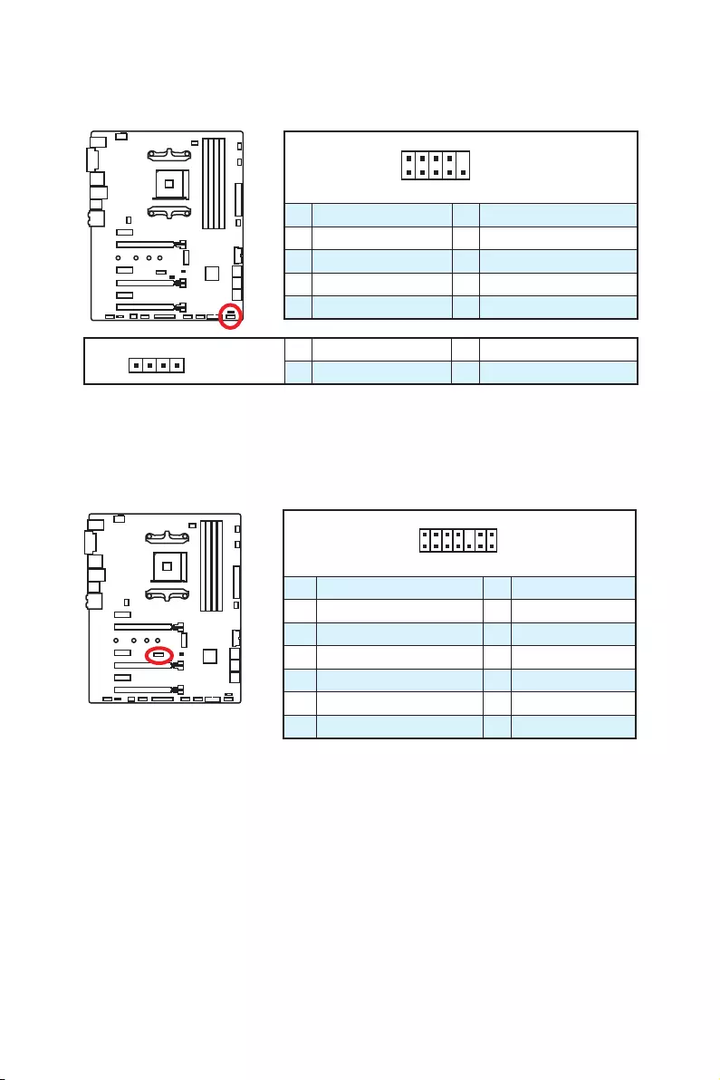
JAUD1: Front Audio Connector
This connector allows you to connect audio jacks on the front panel.
1
2 10
9
1 MIC L 2 Ground
3 MIC R 4 NC
5 Head Phone R 6 MIC Detection
7 SENSE_SEND 8 No Pin
9 Head Phone L 10 Head Phone Detection
JCI1: Chassis Intrusion Connector
This connector allows you to connect the chassis intrusion switch cable.
Normal
(default)
Trigger the chassis
intrusion event
Using chassis intrusion detector
1. Connect the JCI1 connector to the chassis intrusion switch/ sensor on the chassis.
2. Close the chassis cover.
3. Go to BIOS > Settings > Security > Chassis Intrusion Configuration.
4. Set Chassis Intrusion to Enabled.
5. Press F10 to save and exit and then press the Enter key to select Yes.
6. Once the chassis cover is opened again, a warning message will be displayed on
screen when the computer is turned on.
Resetting the chassis intrusion warning
1. Go to BIOS > Settings > Security > Chassis Intrusion Configuration.
2. Set Chassis Intrusion to Reset.
3. Press F10 to save and exit and then press the Enter key to select Yes.
37
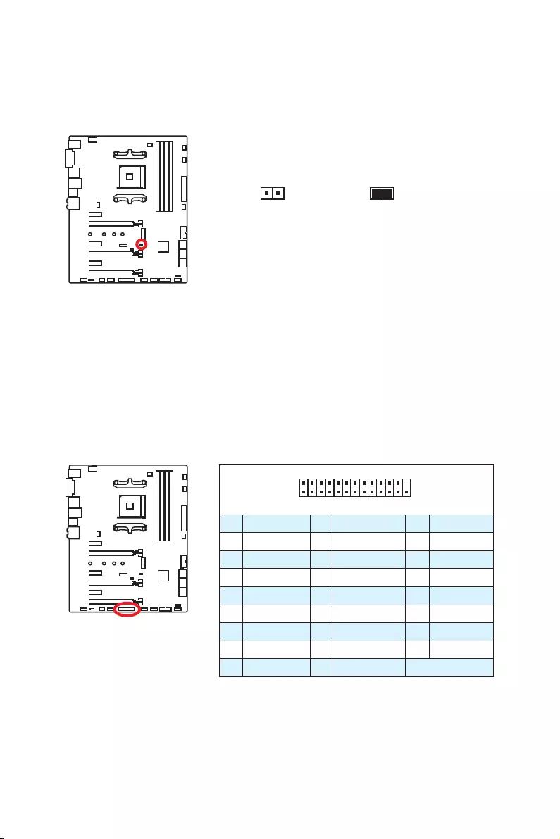
Overview of Components
1
2 14
13
1 LPC Clock 2 3V Standby power
3 LPC Reset 4 3.3V Power
5 LPC address & data pin0 6 Serial IRQ
7 LPC address & data pin1 8 5V Power
9 LPC address & data pin2 10 No Pin
11 LPC address & data pin3 12 Ground
13 LPC Frame 14 Ground
JTPM1: TPM Module Connector
This connector is for TPM (Trusted Platform Module). Please refer to the TPM security
platform manual for more details and usages.
JFP1, JFP2: Front Panel Connectors
These connectors connect to the switches and LEDs on the front panel.
1
2 10
9
JFP1
1 HDD LED + 2 Power LED +
3 HDD LED — 4 Power LED —
5 Reset Switch 6 Power Switch
7 Reset Switch 8 Power Switch
9 Reserved 10 No Pin
1
JFP2
1 Speaker — 2 Buzzer +
3 Buzzer — 4 Speaker +
38 Overview of Components
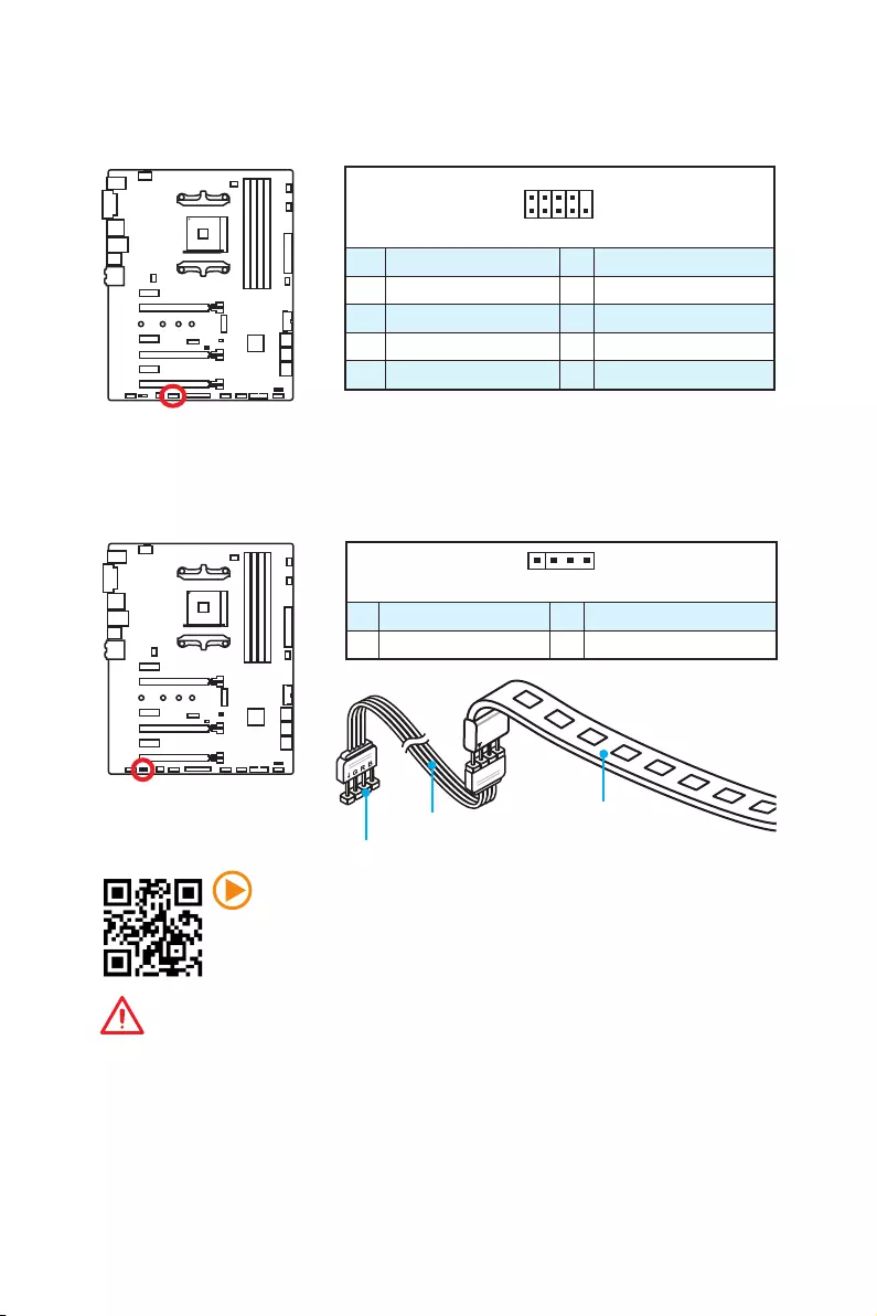
JBAT1: Clear CMOS (Reset BIOS) Jumper
There is CMOS memory onboard that is external powered from a battery located on
the motherboard to save system configuration data. If you want to clear the system
configuration, set the jumpers to clear the CMOS memory.
Keep Data
(default)
Clear CMOS/
Reset BIOS
Resetting BIOS to default values
1. Power off the computer but DO NOT unplug the power cord (system under S5/
Soft-off mode)
2. Use a jumper cap to short JBAT1 for about 5-10 seconds.
3. Remove the jumper cap from JBAT1.
4. Power on the computer.
1
2 26
25
1 RSTB# 2 AFD# 3 PRND0
4 ERR# 5 PRND1 6 PINIT#
7 PRND2 8 LPT_SLIN# 9 PRND3
10 Ground 11 PRND4 12 Ground
13 PRND5 14 Ground 15 PRND6
16 Ground 17 PRND7 18 Ground
19 ACK# 20 Ground 21 BUSY
22 Ground 23 PE 24 Ground
25 SLCT 26 No Pin
JLPT1: Parallel Port Connector
This connector allows you to connect the optional parallel port with bracket.
39
Overview of Components
Important
y
This connector supports 5050 multi-color LED strips with the maximum power
rating of 3A (12V). Please keeping the LED strip shorter than 2 meters to prevent
dimming.
y
Always turn off the power supply and unplug the power cord from the power outlet
before installing or removing the LED strip.
y
Please use GAMING APP to control the extended LED strip.
1
2 10
9
1 DCD 2 SIN
3 SOUT 4 DTR
5 Ground 6 DSR
7 RTS 8 CTS
9 RI 10 No Pin
JCOM1: Serial Port Connector
This connector allows you to connect the optional serial port with bracket.
Video Demonstration
Watch the video to learn how to install 5050 RGB LED strips to RGB LED
connector.
https://youtu.be/CqNHyADzd2Q
JLED1: RGB LED connector
These connectors allow you to connect the 5050 RGB LED strips.
1
JLED1
Extension cable 5050 LED strip
1
1 +12V 2 G
3 R 4 B
40 Onboard LEDs
Onboard LEDs
PCI_E2 LED
PCI_E4 LED
PCI_E6 LED
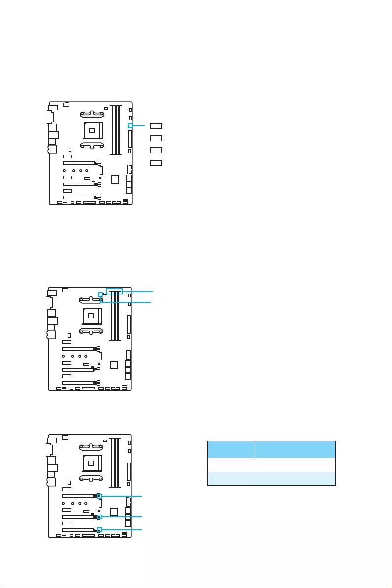
PCIe x16 slot LEDs
These LEDs indicate the PCIe x16 slots status.
LED Color PCIe slot status
Red x16 mode
White x8, x4, x1 mode
GPU LED
DIMM LEDs
EZ Debug LED
These LEDs indicate the debug status of the motherboard.
CPU — indicates CPU is not detected or fail.
DRAM — indicates DRAM is not detected or fail.
VGA — indicates GPU is not detected or fail.
BOOT — indicates the booting device is not detected
or fail.
DIMM LEDs
These LEDs indicate the memory modules are installed.
GPU LED
This LED indicates the CPU’s iGPU is not detected and you need to install a graphics
card.

41
BIOS Setup
BIOS Setup
The default settings offer the optimal performance for system stability in normal
conditions. You should always keep the default settings to avoid possible system
damage or failure booting unless you are familiar with BIOS.
Important
y
BIOS items are continuously update for better system performance. Therefore,
the description may be slightly different from the latest BIOS and should be for
reference only. You could also refer to the HELP information panel for BIOS item
description.
y
The pictures in this chapter are for reference only and may vary from the product
you purchased.
Entering BIOS Setup
Press Delete key, when the Press DEL key to enter Setup Menu, F11 to enter Boot
Menu message appears on the screen during the boot process.
Function key
F1: General Help
F2: Add/ Remove a favorite item
F3: Enter Favorites menu
F4: Enter CPU Specifications menu
F5: Enter Memory-Z menu
F6: Load optimized defaults
F7: Switch between Advanced mode and EZ mode
F8: Load Overclocking Profile
F9: Save Overclocking Profile
F10: Save Change and Reset*
F12: Take a screenshot and save it to USB flash drive (FAT/ FAT32 format only).
* When you press F10, a confirmation window appears and it provides the modification
information. Select between Yes or No to confirm your choice.

42 BIOS Setup
Resetting BIOS
You might need to restore the default BIOS setting to solve certain problems. There are
several ways to reset BIOS:
yGo to BIOS and press F6 to load optimized defaults.
yShort the Clear CMOS jumper on the motherboard.
Important
Be sure the computer is off before clearing CMOS data. Please refer to the Clear
CMOS jumper section for resetting BIOS.
Updating BIOS
Updating BIOS with M-FLASH
Before updating:
Please download the latest BIOS file that matches your motherboard model from MSI
website. And then save the BIOS file into the USB flash drive.
Updating BIOS:
1. Press Del key to enter the BIOS Setup during POST.
2. Insert the USB flash drive that contains the update file into the computer.
3. Select the M-FLASH tab and click on Yes to reboot the system and enter the flash
mode.
4. Select a BIOS file to perform the BIOS update process.
5. After the flashing process is 100% completed, the system will reboot
automatically.
Updating the BIOS with Live Update 6
Before updating:
Make sure the LAN driver is already installed and the Internet connection is set
properly.
Updating BIOS:
1. Install and launch MSI LIVE UPDATE 6.
2. Select BIOS Update.
3. Click on Scan button.
4. Click on Download icon to download and install the latest BIOS file.
5. Click Next and choose In Windows mode. And then click Next and Start to start
updating BIOS.
6. After the flashing process is 100% completed, the system will restart
automatically.
43
BIOS Setup
EZ Mode
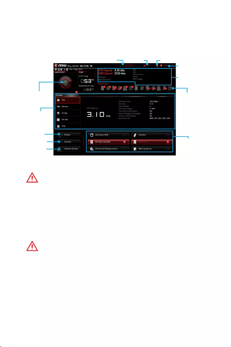
At EZ mode, it provides the basic system information and allows you to configure the
basic setting. To configure the advanced BIOS settings, please enter the Advanced
Mode by pressing the Setup Mode switch or F7 function key.
Information
display
System
information
Boot device
priority bar
Function
buttons
Language
Search
ScreenshotSetup Mode switch
M-Flash
Favorites
Hardware
Monitor
GAME BOOST
switch
yGAME BOOST switch — click on it to toggle the GAME BOOST for OC.
Important
Please don’t make any changes in OC menu and don’t load defaults to keep the
optimal performance and system stability after activating the GAME Boost function.
ySetup Mode switch — press this tab or the F7 key to switch between Advanced mode
and EZ mode.
yScreenshot — click on this tab or the F12 key to take a screenshot and save it to USB
flash drive (FAT/ FAT32 format only).
ySearch — click on this tab or the Ctrl+F keys and the search page will show. It allows
you to search by BIOS item name, enter the item name to find the item listing. Move
the mouse over a blank space and right click the mouse to exit search page.
Important
In search page, only the F6, F10 and F12 function keys are available.
yLanguage — allows you to select the language of BIOS setup.
ySystem information — shows the CPU/ DDR speed, CPU/ MB temperature, MB/ CPU
type, memory size, CPU/ DDR voltage, BIOS version and build date.
yBoot device priority bar — you can move the device icons to change the boot priority.
The boot priority from high to low is left to right.
yInformation display — click on the CPU, Memory, Storage, Fan Info and Help
buttons on left side to display related information.
yFunction buttons — enable or disable the LAN Option ROM, HD audio controller,
AHCI, RAID, CPU Fan Fail Warning Control and BIOS Log Review by clicking on their
respective button.

44 BIOS Setup
Important
y
During windows setup, the RAID driver may be required and you can find the RAID
driver in MSI Driver Disc.
y
You can use MSI SMART TOOL to build the Windows
®
7/ 10 installation drive that
includes RAID driver.
y
If your system currently boots to M.2 SSD RAID and you delete the RAID volume in
the UEFI BIOS, your system will become un-bootable.
yM-Flash — click on this button to display the M-Flash menu that provides the way to
update BIOS with a USB flash drive.
yHardware Monitor — click on this button to display the Hardware Monitor menu that
allows you to manually control the fan speed by percentage.
yFavorites — press the Favorites tab or the F3 key to enter Favorites menu. It
allows you to create personal BIOS menu where you can save and access favorite/
frequently-used BIOS setting items.
Default HomePage — allows you to select a BIOS menu (e.g. SETTINGS, OC…,etc)
as the BIOS home page.
Favorite1~5 — allows you to add the frequently-used/ favorite BIOS setting items in
one page.
To add a BIOS item to a favorite page (Favorite 1~5)
1. Move the mouse over a BIOS item not only on BIOS menu but also on search
page.
2. Right-click or press F2 key.
3. Choose a favorite page and click on OK.
To delete a BIOS item from favorite page
1. Move the mouse over a BIOS item on favorite page (Favorite 1~5)
2. Right-click or press F2 key.
3. Choose Delete and click on OK.
45
BIOS Setup
Advanced Mode
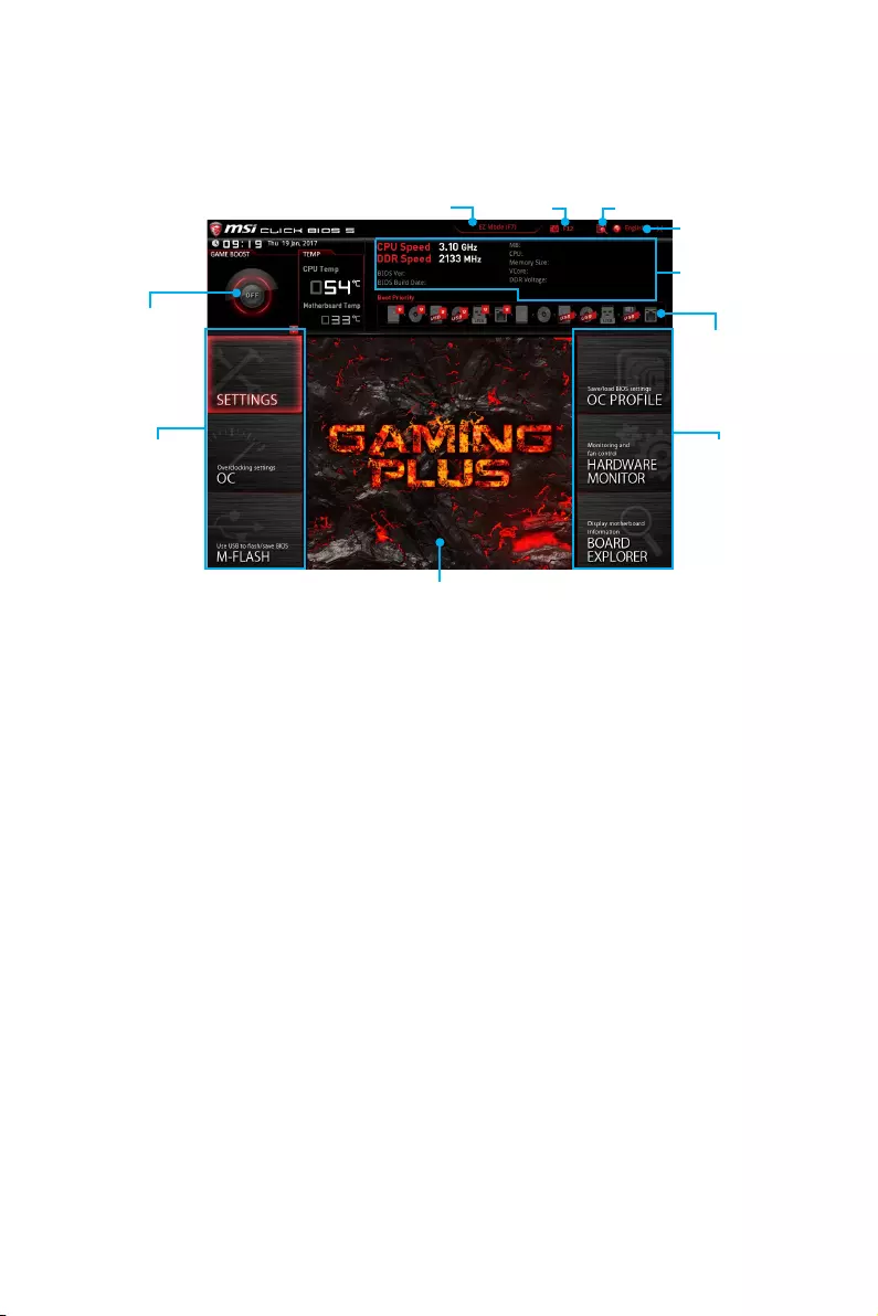
Press Setup Mode switch or F7 function key can switch between EZ Mode and
Advanced Mode in BIOS setup.
GAME BOOST
switch
System
information
Boot device
priority bar
BIOS menu
selection
Language
SearchScreenshotSetup Mode switch
Menu display
BIOS menu
selection
yGAME BOOST switch/ Setup Mode switch/ Screenshot/ Favorites/ Language/
System information/ Boot device priority bar — please refer to the descriptions of
EZ Mode Overview section.
yBIOS menu selection — the following options are available:
SETTINGS — allows you to specify the parameters for chipset and boot devices.
OC — allows you to adjust the frequency and voltage. Increasing the frequency may
get better performance.
M-FLASH — provides the way to update BIOS with a USB flash drive.
OC PROFILE — allows you to manage overclocking profiles.
HARDWARE MONITOR — allows you to set the speeds of fans and monitor voltages
of system.
BOARD EXPLORER — provides the information of installed devices on this
motherboard.
yMenu display — provides BIOS setting items and information to be configured.
46 BIOS Setup
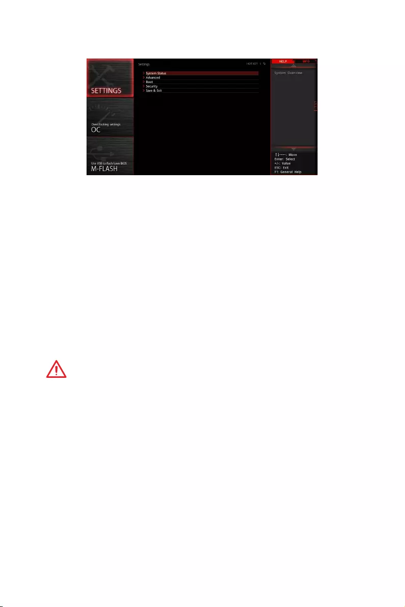
SETTINGS
System Status
fSystem Date
Sets the system date. Use tab key to switch between date elements.
The format is <day> <month> <date> <year>.
<day> Day of the week, from Sun to Sat, determined by BIOS. Read-only.
<month> The month from Jan. through Dec.
<date> The date from 1 to 31 can be keyed by numeric function keys.
<year> The year can be adjusted by users.
fSystem Time
Sets the system time. Use tab key to switch between time elements.
The time format is <hour> <minute> <second>.
fSATA PortX
Shows the information of connected SATA devices.
Important
If the connected SATA device is not displayed, turn off computer and re-check SATA
cable and power cable connections of the device and motherboard.
fSystem Information
Shows detailed system information, including CPU type, BIOS version, and Memory
(read only).
fDMI Information
Shows system information, desktop Board Information and chassis Information. (Read
only).
Advanced
fPCI Subsystem Settings
Sets PCI, PCI express interface protocol and latency timer. Press Enter to enter the
sub-menu.

47
BIOS Setup
fPCI Latency Timer [32]
Sets latency timer of PCI interface device.
[Options: 32, 64, 96, 128, 160, 192, 224, 248 PCI Bus clocks]
fACPI Settings
Sets ACPI parameters of onboard power LED behaviors. Press Enter to enter the sub-
menu.
fPower LED [Blinking]
Sets shining behaviors of the onboard Power LED.
[Dual Color] The power LED turns to another color to indicate the S3 state.
[Blinking] The power LED blinks to indicate the S3 state.
fIntegrated Peripherals
Sets integrated peripherals’ parameters, such as LAN, HDD, USB and audio. Press
Enter to enter the sub-menu.
fOnboard LAN Controller [Enabled]
Enables or disables the onboard LAN controller.
fLAN Option ROM [Disabled]
Enables or disables the legacy network Boot Option ROM for detailed settings. This
item will appear when Onboard LAN Controller is enabled.
[Enabled] Enables the onboard LAN Boot ROM.
[Disabled] Disables the onboard LAN Boot ROM.
fNetwork Stack [Disabled]
Sets UEFI network stack for optimizing IPv4 / IPv6 function. This item is available
when Onboard LAN Controller is Enabled.
[Enabled] Enables UEFI network stack.
[Disabled] Disables UEFI network stack.
fIpv4 PXE Support [Enabled]
When Enabled, the system UEFI network stack will support Ipv4 protocol. This item
will appear when Network Stack is Enabled.
[Enabled] Enables the Ipv4 PXE boot support.
[Disabled] Disables the Ipv4 PXE boot support.
fIpv6 PXE Support [Enabled]
When Enabled, the system UEFI network stack will support Ipv6 protocol. This item
will appear when Network Stack is enabled.
[Enabled] Enables the Ipv6 PXE boot support.
[Disabled] Disables the Ipv6 PXE boot support.

48 BIOS Setup
fSATA Mode [AHCI Mode]
Sets the operation mode of the onboard SATA controller.
[AHCI Mode] Specify the AHCI mode for SATA storage devices. AHCI (Advanced
Host Controller Interface) offers some advanced features to enhance
the speed and performance of SATA storage device, such as Native
Command Queuing (NCQ) and hot-plugging.
[RAID Mode] Enables RAID function for SATA storage devices.
fSATAx Hot Plug [Disabled]
Allows user to enable or disable the SATA hot plug support.
[Enabled] Enables hot plug support for the SATA ports.
[Disabled] Disables hot plug support for the SATA ports.
fHD Audio Controller [Enabled]
Enables or disables the onboard High Definition Audio controller.
fIntegrated Graphics Configuration
Adjusts integrated graphics settings for optimum system. Press Enter to enter the
sub-menu.
fPrimary Video Adapter [PEG] (optional)
Selects a graphics device as the primary boot device. This item appears when the
installed CPU has iGPU.
[IGD] Integrated Graphics Display.
[PEG] PCI-Express Graphics Device.
fIntegrated Graphics [Auto] (optional)
If set to Force, BIOS will enable the integrated graphics controller.
fUMA Frame Buffer Size [Auto] (optional)
Selects a fixed amount of system memory allocated to the onboard graphics. This
item will be available when Integrated Graphics is enabled.
fUSB Configuration
Sets the onboard USB controller and device function. Press Enter to enter the sub-
menu.
fXHCI Hand-off [Enabled]
Enables or disables XHCI hand-off support for the operating system without XHCI
hand-off feature.
fLegacy USB Support [Enabled]
Sets Legacy USB function support.
[Auto] The system will automatically detect if any USB device is connected
and enable the legacy USB support.
[Enabled] Enable the USB support under legacy mode.
[Disabled] The USB devices will be unavailable under legacy mode.

49
BIOS Setup
fSuper IO Configuration
Sets system Super I/O chip parameters including LPT and COM ports. Press Enter to
enter the sub-menu.
fSerial (COM) Port x Configuration
Sets detailed configuration of serial(COM) port x. Press Enter to enter the sub-
menu.
fSerial (COM) Port x [Enabled]
Enables or disables serial (COM) port x.
fSerial (COM) Port x Settings [Auto]
Sets serial port x (COM). If set to Auto, BIOS will optimize the IRQ automatically or
you can set it manually.
fParallel (LPT) Port Configuration
Sets detailed configuration of parallel port (LPT/ LPTE). Press Enter to enter the
sub-menu.
fParallel (LPT) Port [Enabled]
Enables or disables parallel(LPT/ LPTE) port.
fParallel (LPT) Port Settings [Auto]
Sets parallel port (LPT). If set to Auto, BIOS will optimize the IRQ automatically or
you can set it manually.
fDevice Mode [STD Printer Mode]
Selects an operating mode for parallel port.
[STD Printer Mode] Printer port mode
[SPP] Standard Parallel Port mode
[EPP-1.9 and SPP Mode] Enhanced Parallel Port-1.9 mode + Standard
Parallel Port mode.
fPower Management Setup
Sets system Power Management of ErP Ready and AC Power Loss behaviors. Press
Enter to enter the sub-menu.
fErP Ready [Disabled]
Enables or disables the system power consumption according to ErP regulation.
[Enabled] Optimize the system power consumption according to ErP
regulation. It will not support S4 & S5 wake up by USB and PCIe
devices.
[Disabled] Disables this function.
fRestore after AC Power Loss [Power Off]
Sets the system behaviors while encountering the AC power loss.
[Power Off] Leaves the system in power off state after restoring AC power.
[Power On] Boot up the system after restoring AC power.
[Last State] Restores the system to the previous state (power on/ power off)
before AC power loss.

50 BIOS Setup
fSystem Power Fault Protection [Disabled]
Enables or disables the system to boot up when detecting abnormal voltage input.
[Enabled] Protect the system from unexpected power operating and remain
the shut down status.
[Disabled] Disables this function.
fWindows OS Configuration
Sets Windows detailed configuration and behaviors. Press Enter to enter the sub-
menu.
fWindows 10 WHQL Support [Disabled]
Enables the supports for Windows 10 or disables for other operating systems.
Before enabling this item, make sure all installed devices & utilities (hardware &
software) should meet the Windows 10 requirements.
[Enabled] The system will switch to UEFI mode to meet the Windows
requirement.
[Disabled] Disables this function.
fInternal GOP Configuration
Manages the onboard Graphics Output Protocol (GOP). Press Enter to enter
the sub-menu. This sub-menu will appear when Windows 10 WHQL Support is
enabled.
fSecure Boot
Sets the Windows secure boot to prevent the unauthorized accessing. Press Enter
to enter the sub-menu. This sub-menu will appear when Windows 10 WHQL
Support is enabled.
fWake Up Event Setup
Sets system wake up behaviors for different sleep modes. Press Enter to enter the
sub-menu.
fWake Up Event By [BIOS]
Selects the wake up event by BIOS or operating system.
[BIOS] Activates the following items, set wake up events of these items.
[OS] The wake up events will be defined by OS.
fResume By RTC Alarm [Disabled]
Disables or enables the system wake up by RTC Alarm.
[Enabled] Enables the system to boot up on a scheduled time/ date.
[Disabled] Disables this function.
fDate (of month) Alarm/ Time (hh:mm:ss) Alarm
Sets RTC alarm date/ Time. If Resume By RTC Alarm is set to [Enabled], the system
will automatically resume (boot up) on a specified date/hour/minute/second in
these fields (using the + and — keys to select the date & time settings).

51
BIOS Setup
fResume By PCI-E Device [Disabled]
Enables or disables the wake up function of installed PCI/ PCI-E expansion cards,
integrated LAN controllers or USB devices which are supported by third party
integrated chips.
[Enabled] Enables the system to be awakened from the power saving modes
when activity or input signal of PCI/ PCIe device is detected.
[Disabled] Disables this function.
fResume by USB Device [Disabled]
Disables or enables system wake up from S3/S4 by USB device.
[Enabled] Enables the system to be awakened from sleep state when activity of
USB device is detected.
[Disabled] Disables this function.
fResume From S3/S4/S5 by PS/2 Mouse [Disabled]
Enables or disables the system wake up by PS/2 mouse.
[Enabled] Enables the system to be awakened from S3/ S4/ S5 state when
activity of PS/2 mouse is detected.
[Disabled] Disables this function.
fResume From S3/S4/S5 by PS/2 Keyboard [Disabled]
Enables or disables the system wake up by PS/2 keyboard.
[Any Key] Enables the system to be awakened from S3/ S4/ S5 state when
activity of any key on PS/2 keyboard is detected.
[Hot Key] Enables the system to be awakened from S3/ S4/ S5 state when
activity of hot key on PS/2 keyboard is detected.
[Disabled] Disables this function.
fHot Key [Ctrl+Space]
Selects a combination of keys as a hot key to wake the system. This item appears
when you set the Resume From S3/S4/S5 by PS/2 Keyboard to Hot Key.
fSecure Erase+
Enables or disables Secure Erase+ function. Secure Erase+ is the best way to
effectively wipe all data from a SSD. Please note that data of SSD will be erased after
enabling Secure Erase+.
fRealtek PCIe GBE Family Controller
Shows driver information and configuration of the ethernet controller parameter.
Boot
Sets the sequence of system boot devices.
fFull Screen Logo Display [Enabled]
Enables or disables to show the full screen logo while system POST.
[Enabled] Shows the logo in full screen.
[Disabled] Shows the POST messages.

52 BIOS Setup
fBootup NumLock State [On]
Select the keyboard NumLock state upon bootup.
fInfo Block effect [Unlock]
Sets the state of Help information block.
[Unlock] Sliding effect.
[Lock] Fix the Help information block on the screen.
fAUTO CLR_CMOS [Disabled]
Enables or disables the CMOS data to be resumed automatically when the system
cannot boot to OS and reboot repeatedly.
fBoot Mode Select [LEGACY+UEFI]
Sets the system boot mode from legacy or UEFI architecture depending on OS
installation requirement. This item will become un-selectable and will be configured
automatically by BIOS when Windows 10 WHQL Support is enabled.
[UEFI] Enables UEFI BIOS boot mode support only.
[LEGACY+UEFI] Enables both Legacy BIOS boot mode and UEFI BIOS boot
mode.
fFIXED BOOT ORDER Priorities
Sets device priority for system boot.
fBoot Option Priorities
These items are used to prioritize the installed boot devices.
Security
fAdministrator Password
Sets administrator password for system security. User has full rights to change the
BIOS items with administrator password. After setting the administrator password, the
state of this item will show Installed.
fUser Password
Sets User Password for system security. User has limited rights to change the BIOS
items with user password. This item will be available when administrator password is
set. After setting the user password, the state of this item will show Installed.
fPassword Check [Setup]
Selects a condition that will request the password.
[Setup] A password will be requested for entering the BIOS Setup.
[Boot] A password will be requested for booting the system.
fPassword Clear [Enabled]
Enables or disables the clear CMOS behavior to clear a set password.
[Enabled] The password will be erased after clear CMOS.
[Disabled] The password will always be kept.

53
BIOS Setup
Important
When selecting the Administrator / User Password items, a password box will appear
on the screen. Type the password then press Enter. The password typed now will
replace any previous set password from CMOS memory. You will be prompted to
confirm the password. You may also press Esc key to abort the selection.
To clear a set password, press Enter when you are prompted to enter a new password.
A message will confirm the password is being disabled. Once the password is disabled,
you can enter the setup and OS without authorization.
fTrusted Computing
Sets TPM (Trusted Platform Module) function.
fSecurity Device Support [Disabled]
Enables or disables the TPM function to build the endorsement key for accessing
the system.
fAMD fTPM switch [AMD CPU fTPM]
Selects TPM device.
[AMD CPU fTPM] Select it for AMD Firmware TPM.
[AMD CPU fTPM Disabled] Select it for Discrete TPM.
fDevice Select [Auto]
Sets the version of the TPM device. The version must be identical with the device.
Sets to Auto, system will detect the TPM2.0 or TPM1.2 model automatically.
fChassis Intrusion Configuration
Press Enter to enter the sub-menu.
fChassis Intrusion [Disabled]
Enables or disables recording messages while the chassis is opened. This function
is ready for the chassis equips a chassis intrusion switch.
[Enabled] Once the chassis is opened, the system will record and issue a
warning message.
[Reset] Clear the warning message. After clearing the message, please
return to Enabled or Disabled.
[Disabled] Disables this funcion.
Save & Exit
fDiscard Changes and Exit
Exit BIOS setup without saving any change.
fSave Changes and Reboot
Save all changes and reboot the system.
fSave Changes
Save current changes.

54 BIOS Setup
fDiscard Changes
Discard all changes and restore to the previous values.
fRestore Defaults
Restore or load all default values.
fBoot Override
The installed boot-able devices will appear on this menu, you can select one of them to
be the boot device.
55
BIOS Setup
OC
Important
y
Overclocking your PC manually is only recommended for advanced users.
y
Overclocking is not guaranteed, and if done improperly, it could void your warranty
or severely damage your hardware.
y
If you are unfamiliar with overclocking, we advise you to use GAME BOOST function
for easy overclocking.
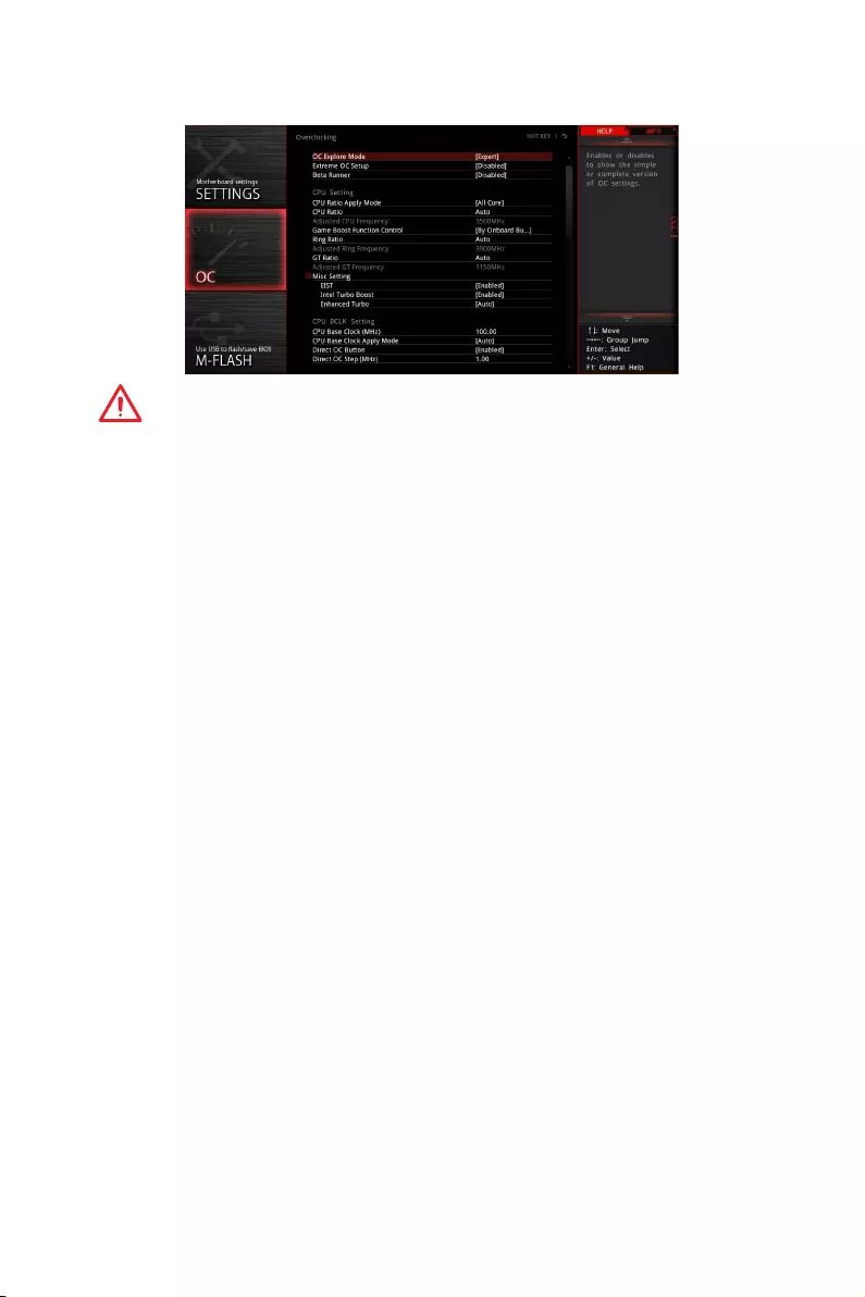
fOC Explore Mode [Normal]
Enables or disables to show the normal or expert version of OC settings.
[Normal] Provides the regular OC settings in BIOS setup.
[Expert] Provides the advanced OC settings for OC expert to configure in BIOS
setup.
Note: We use * as the symbol for the OC settings of Expert mode.
fCPU Frequency [Auto]
Sets the CPU frequency.
fCore Performance Boost [Auto]
Enables or disables the Core Performance Boost (CPB). This item appears when the
installed CPU supports this function.
fDowncore Control [Auto] (optional)
Sets the number of processor cores to be used. This item appears when the installed
CPU supports this function.
fDRAM Frequency [Auto]
Sets the DRAM frequency. Please note the overclocking behavior is not guaranteed.
fAdjusted DRAM Frequency
Shows the adjusted DRAM frequency. Read-only.
fAdvanced DRAM Configuration
Press Enter to enter the sub-menu. User can set the memory timing for each/ all
memory channel. The system may become unstable or unbootable after changing
memory timing. If it occurs, please clear the CMOS data and restore the default
settings. (Refer to the Clear CMOS jumper/ button (optional) section to clear the CMOS
data, and enter the BIOS to load the default settings.)

56 BIOS Setup
fDigitALL Power
Press Enter to enter the sub-menu. Controls the digital powers related to CPU PWM.
fCPU Loadline Calibration Control [Auto]
The CPU voltage will decrease proportionally according to CPU loading. Higher
load-line calibration could get higher voltage and good overclocking performance,
but increase the temperature of the CPU and VRM. If set to Auto, BIOS will
configure this setting automatically.
fCPU NB Loadline Calibration Control [Auto]
The CPU-NB voltage will decrease proportionally according to CPU-NB loading.
Higher load-line calibration could get higher voltage and good overclocking
performance, but increase the temperature. If set to Auto, BIOS will configure this
setting automatically.
fCPU Over Voltage Protection [Auto]
Sets the voltage limit for CPU over-voltage protection. If set to Auto, BIOS will
configure this setting automatically. Higher voltage provides less protection and
may damage the system.
fCPU Under Voltage Protection [Auto]
Sets the voltage limit for CPU under-voltage protection. If set to Auto, BIOS will
configure this setting automatically. Higher voltage provides less protection and
may damage the system.
fCPU Over Current Protection [Auto]
Sets the current limit for CPU over-current protection. If set to Auto, BIOS will
configure this setting 0utomatically.
[Auto] This setting will be configured automatically by BIOS.
[Enhanced] Extends the current range for over-current protection.
fVR 12VIN OCP Expander [Auto]
Expands the limitation of VR Over Current Protection with 12V input voltage. The
higher expanding value indicates less protection. Therefore, please adjust the
current carefully if needed, or it may damage the CPU/ VR MOS. If set to «Auto»,
BIOS will configure this setting automatically.
fCPU Voltages control [Auto]
These options allows you to set the voltages related to CPU. If set to Auto, BIOS will
set these voltages automatically or you can set it manually.
fDRAM/PROM Voltages control [Auto]
These options allows you to set the voltages related to memory. If set to Auto, BIOS
will set these voltages automatically or you can set it manually.
fCPU Memory Changed Detect [Enabled]*
Enables or disables the system to issue a warning message during boot when the CPU
or memory has been replaced.
[Enabled] The system will issue a warning message during boot and then you have
to load the default settings for new devices.
[Disabled] Disables this function and keeps the current BIOS settings.

57
BIOS Setup
fCPU Specifications
Press Enter to enter the sub-menu. This sub-menu displays the information of
installed CPU. You can also access this information menu at any time by pressing [F4].
Read only.
fCPU Technology Support
Press Enter to enter the sub-menu. The sub-menu shows the key features of
installed CPU. Read only.
fMEMORY-Z
Press Enter to enter the sub-menu. This sub-menu displays all the settings and
timings of installed memory. You can also access this information menu at any time by
pressing [F5].
fDIMMx Memory SPD
Press Enter to enter the sub-menu. The sub-menu displays the information of
installed memory. Read only.
fCPU Features
Press Enter to enter the sub-menu.
fAMD Cool’n’Quiet [Enabled]
The Cool’n’Quiet technology can effectively and dynamically lower CPU speed and
power consumption.
fSVM Mode [Disabled]
Enables/ disables the AMD SVM (Secure Virtual Machine) Mode.
fCore C6 state [Enabled]
Enables/disables the C6 state.
58 BIOS Setup
M-FLASH
M-FLASH provides the way to update BIOS with a USB flash drive. Please down-load
the latest BIOS file that matches your motherboard model from MSI website, save the
BIOS file into your USB flash drive. And then follow the steps below to update BIOS.
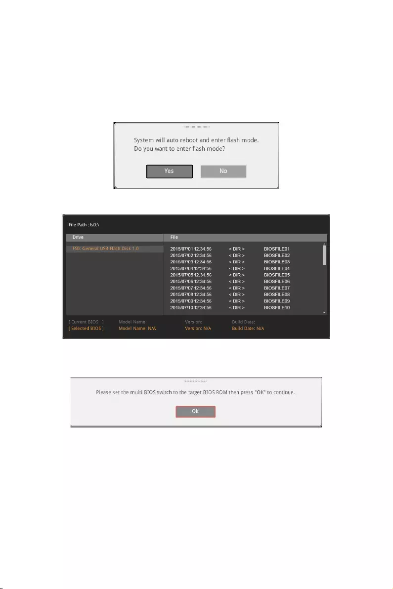
1. Insert the USB flash drive that contains the update file into the computer.
2. Click on M-FLASH tab, a demand message will be prompted. Click on Yes to
reboot and enter the flash mode.
3. The system will enter the flash mode and a file selection menu will appear after
rebooting.
4. Select the BIOS file.
5. A message will prompt you to toggle the Multi BIOS switch to the target BIOS ROM,
and then click OK to perform the BIOS update process.
6. After the flashing process is 100% completed, the system will reboot
automatically.
59
BIOS Setup
OC PROFILE
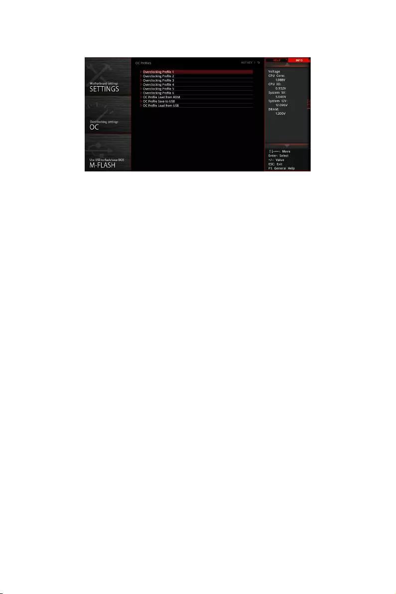
fOverclocking Profile 1/ 2/ 3/ 4/ 5/ 6
Overclocking Profile 1/ 2/ 3/ 4/ 5/ 6 management. Press <Enter> to enter the sub-
menu.
fSet Name for Overclocking Profile 1/ 2/ 3/ 4/ 5/ 6
Name the current overclocking profile.
fSave Overclocking Profile 1/ 2/ 3/ 4/ 5/ 6
Save the current overclocking profile.
fLoad Overclocking Profile 1/ 2/ 3/ 4/ 5/ 6
Load the current overclocking profile.
fClear Overclocking Profile 1/ 2/ 3/ 4/ 5/ 6
Clear the current overclocking profile.
fOC Profile Load from ROM
Load OC profile from BIOS ROM.
fOC Profile Save to USB
Save OC profile to the USB flash drive. The USB flash drive should be FAT/ FAT32
format only.
fOC Profile Load from USB
Load OC profile from the USB flash drive. The USB flash drive should be FAT/ FAT32
format only.
60 BIOS Setup
HARDWARE MONITOR
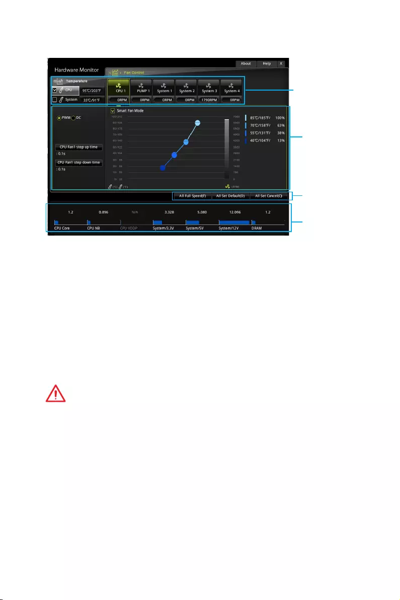
Temperature
& Speed
Fan Manage
Voltage
display
Setting
Buttons
fTemperature & Speed
Shows the current CPU temperature, system temperature and fans’ speeds.
fFan Manage
PWM — allows you to select the PWM mode for fan operation.
DC — allows you to select the DC mode for fan operation.
Auto — allows you to select the Auto-detection mode for fan operation.
Fan step up/ down time — allows you to set the period of fan step up/ down.
Smart Fan Mode field — allows you to drag the gradient points to configure the
fan target values for Smart Fan mode. Smart Fan can control the fan speed
automatically depending on the CPU temperature to keep it with in a specific
range. If the current CPU temperature reaches to the target value, the Smart Fan
function will be activated.
Important
y
The changing will achieve after you save the changes and reboot the system.
y
Make sure fans are working properly after switching the PWM/ DC mode.
fSettings Buttons
All Full Speed — configures all fans to run at full operating speed.
All Set Default — configures all fans to run at default operating speed.
All Set Cancel — discards current changes and restores previous operating fan
speeds .
fVoltage display
Shows the current voltages of CPU, system and memory.

61
Software Description
Software Description
Please download and update the latest utilities and drivers at www.msi.com
Installing Windows® 7 64-bit/ Windows®10 64—bit
1. Power on the computer.
2. Insert the Windows® 7/ 10 disc into your optical drive.
Note: Due to chipset limitation, during the Windows 7 installation process, USB
optical drives or USB flash drives are not supported. You can use MSI Smart Tool
to install Windows
®
7.
3. Press the Restart button on the computer case.
4. Press F11 key during the computer POST (Power-On Self Test) to get into Boot
Menu.
5. Select your optical drive from the Boot Menu.
6. Press any key when screen shows Press any key to boot from CD or DVD…
message.
7. Follow the instructions on the screen to install Windows® 7/ 10.
Installing Drivers
1. Start up your computer in Windows® 7/ 10.
2. Insert MSI® Driver Disc into your optical drive.
3. The installer will automatically appear and it will find and list all necessary
drivers.
4. Click Install button.
5. The software installation will then be in progress, after it has finished it will
prompt you to restart.
6. Click OK button to finish.
7. Restart your computer.
Installing Utilities
Before you install utilities, you must complete drivers installation.
1. Insert MSI® Driver Disc into your optical drive.
2. The installer will automatically appear.
3. Click Utilities tab.
4. Select the utilities you want to install.
5. Click Install button.
6. The utilities installation will then be in progress, after it has finished it will prompt
you to restart.
7. Click OK button to finish.
8. Restart your computer.
62 Software Description
LIVE UPDATE 6
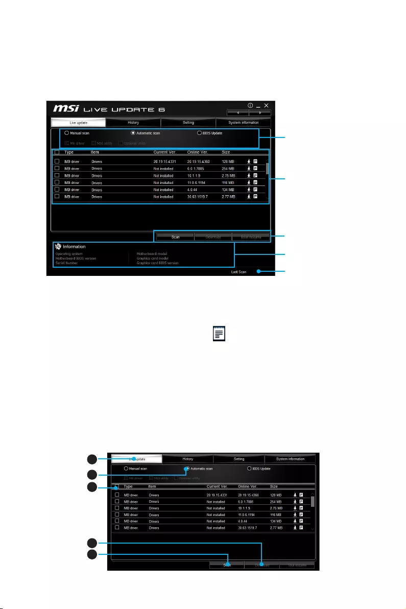
LIVE UPDATE 6 is an application for the MSI® system to scan and download the latest
drivers, BIOS and utilities. With LIVE UPDATE 6, you don’t need to search the drivers
on websites, and don’t need to know the models of motherboard and graphics cards.
LIVE UPDATE 6 will download the appropriate drivers automatically.
Download Options
Download List
Scan / Download / Total
Installer button
System Information
Last Scanned Date
There are Live Update, History, Setting and System Information tabs at the top. You
can click the tab to switch the control panel.
yLive Update — When you launch LIVE UPDATE 6, you will see the Live update tab at
first. This tab allows you to select files to download. You can also read the relevant
information by clicking the information icon on the right of the item listed.
yHistory — shows the downloading history.
ySetting — allows you to specify the frequency that LIVE UPDATE 6 remind you to
update.
ySystem Information — displays the information of the system.
yFAQ — shows Frequently Asked Questions.
yOnline Help — shows Online Help information.
Updating The System
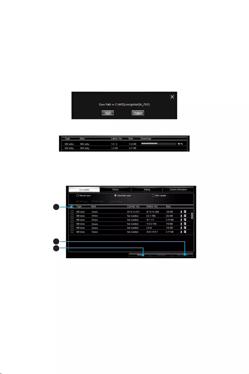
This section describes how to update your system with LIVE UPDATE 6. Please follow
the steps below:
1
2
4
5
3
63
Software Description
1. Select the Live Update tab.
2. Choose Automatic scan, system will automatically scan all the items and search
for the latest update files. Or you can choose Manual scan and select the items you
wish to scan.
3. Click the Scan button at the bottom. It may take several moments to complete the
process.
4. When the download list appears, please select the items you intend to update.
5. Click Download button at the bottom.
6. When Save Path prompt, you can specify a download directory.
7. When downloading you will see the screen below. It may take several moments to
complete the process.
8. To install the applications, simply unpack the packages and install.
Total Installer
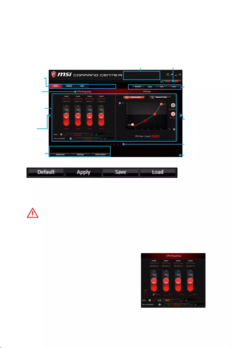
Total Installer is a convenient feature to simplify frequent installing procedure. To use
Total Installer:
1
2
3
1. Scan updates in Live Update tab.
2. Check the Select All check-box you intend to update.
3. Click the Total Installer button. LIVE UPDATE 6 will automatically install them.
4. When prompted, click OK to complete the Total Installer procedure
5. Reboot your system.
64 Software Description
COMMAND CENTER
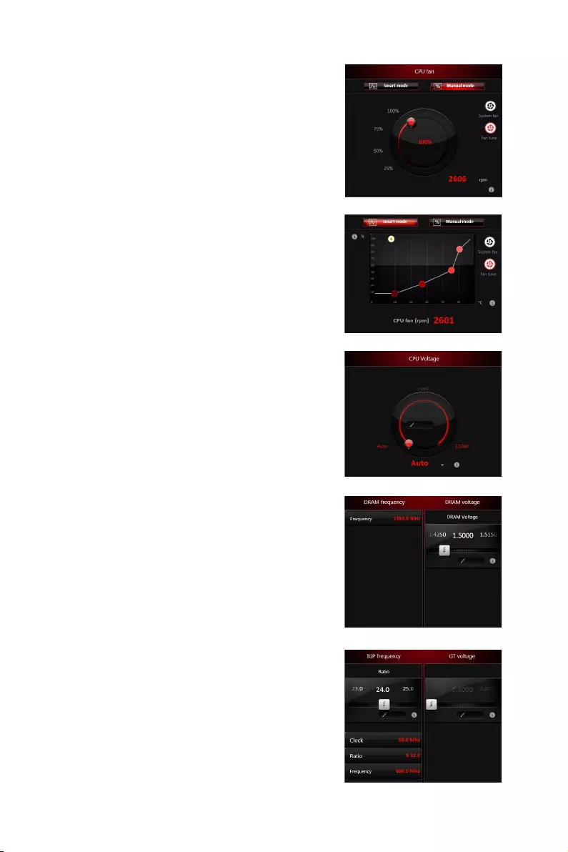
COMMAND CENTER is an user-friendly software and exclusively developed by MSI,
helping users to adjust system settings and monitor status under OS. With the help
of COMMAND CENTER, making it possible to achieve easier and efficient monitoring
process and adjustments than that under BIOS. In addition, the COMMAND CENTER
can be a server for mobile remote control application.
Feature Menu
CPU TemperatureSystem Information
Feature Title
Feature
Control Panel
Previous
Feature
Next Feature
Profile
Buttons
Option Buttons
Page Indicator
Resize Corner
Profile Buttons
yDefault — load the default values for the current feature.
yApply — apply your changes.
ySave — store values in the file with individual file extension.
yLoad — load the values from the file.
Important
Every time you shut down the system, the configured setting will be restored to the
factory default. If you want to use the saved settings, you have to load it every time by
clicking the Load and Apply buttons.
CPU Frequency
CPU Frequency control panel allows you to change
CPU Ratio and Base clock. You can see the current
frequency of each CPU core on the top of the panel.
65
Software Description
CPU Fan
CPU Fan control panel provides Smart mode and
Manual Mode. You can switch the control mode by
clicking the Smart Mode and Manual Mode buttons
on the top of the CPU Fan control panel.
yManual Mode — allows you to manually control the
CPU fan speed by percentage.
ySmart Mode — a linear fan speed control feature.
The control panel contains 4 dots allows you to
drag and adjust the Smart Speed slopes. The fan
speed will be changed along these lines with CPU
temperature. The white dot will create strip chart
in real time.
ySystem Fan Button — to open the system fan
control panel in new window.
yFan Tune Button — to automatically optimize the
smart fan setting.
Manual Mode
Smart Mode
IGP Frequency & GT Voltage
yIGP Frequency — Allows you to adjust the IGP ratio,
and shows the IGP clock, ratio and frequency.
yGT Voltage — Allows you to adjust the GT voltage.
The risky values are displayed in red.
DRAM Frequency & DRAM Voltage
yDRAM Frequency — Shows the DRAM clock, ratio
and frequency.
yDRAM Voltage — Allows you to adjust the DRAM
voltage. The risky values are displayed in red.
CPU Voltage
CPU Voltage control panel allows you to control the
CPU voltage.
66 Software Description
Option Buttons — Advanced
When click the Advanced button, The Voltage, Fan, DRAM and Sensor icons will
appear.
yVoltage — allows you to adjust advanced voltage values of CPU and chipset.
yFan — allows you to control the system fans speed.
yDRAM — shows the current Advanced DRAM parameters, and allows you to change
the settings by selecting values from the drop-down menu on the right hand side.
ySensor — allows you to monitor your motherboard temperature and fan speed with
the virtual thermal image. You can drag and drop the fan icons to new locations.
When you press the Cooling button, all fans will run at full speed.
Option Buttons — Setting
When click the Setting button, The Record, Warning and Mobile Control icons will
appear.
yRecord — allows you to monitor the status of voltage, fan speed and temperature in
real time.
To filter record charts, select the check box next to the items.
When click the Play button, the chart pane will start to show the recording chart.
If you want to check the value of a specific spot on chart, please move the orange
vertical line to the spot.
History Record stores the data and names with date and time.
To make a history record: Select items and click the Record button. When finished,
click the Record button again. The data will be stored in the drop-down menu.
To load a record, click the drop-down menu and select one from the list.
To delete a record, select the record that you want to delete, and click the Trash
Can icon.
GAME BOOST
GAME BOOST provides a specified CPU frequency for
overclocking the CPU.
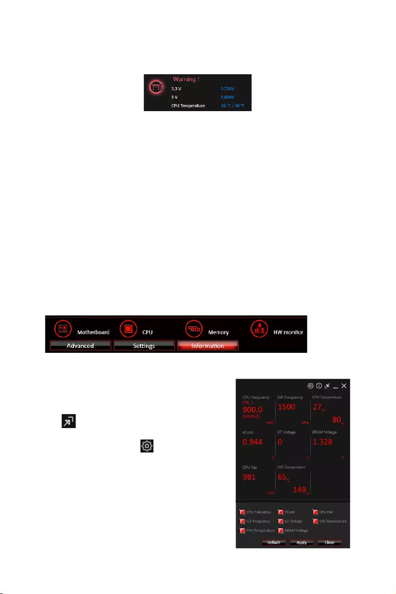
67
Software Description
yWarning — contains fields of voltage, fan speed and temperature for you to set the
threshold values. When system detects the status over your settings, a warning
message will pop-up.
yMobile Control — is only available for the motherboard with the built-in WiFi module.
It allows you to enable/disable the COMMAND CENTER Remote Server. Please
refer to the instruction on the Mobile Control control panel.To start remote control:
(optional)
1. Download and install MSI® COMMAND CENTER APP to your mobile device.
2. Enable COMMAND CENTER Remote Server on the Mobile Control panel.
3. Enable SoftAP Management.
4. Enter SSID and Password, and then click the Apply button.
5. Activate Wi-Fi® on your mobile device and connect to SoftAP with the SSID.
6. Run MSI® COMMAND CENTER APP on your mobile device.
7. Find the IP address on the SoftAP Management Setting area, and enter the IP
address on your MSI® COMMAND CENTER APP to link your system.
8. Press Refresh on the MSI® COMMAND CENTER APP to verify that monitoring and
OC functions are working properly.
Option Buttons — Information
When click the Information button, The Motherboard, CPU, Memory and HW monitor
icons will appear.
You can click the icons to open the related information.
Gadget Mode
COMMAND CENTER provides a gadget mode to
monitor the system status. You can switch between
gadget mode and full mode by clicking the arrow
icon on the top left.
yTo arrange gadgets:
1. Click the Spanner icon on the Gadget mode,
a configuration panel will slide out.
2. Select the check box next to the items.
3. Click the Close button.

68 Software Description
GAMING APP
GAMING APP is an application designed to quickly control your system for improving
gaming performance.
Information Button
Setting Button
Control Mode Buttons
Gaming Function
Buttons
CPU Frequency
Peripheral Device
Function Buttons
Remote Control Setting Button
ySetting Button — allows you to choose running GAMING APP when Windows starts or
let GAMING APP to overwrite the VGA fan control function.
yInformation Button — shows the information of this application.
yCPU Frequency — shows the current CPU frequency.
yControl Mode Buttons
OC Mode — apply turbo frequency to CPU and OC frequency to GPU.
Gaming Mode — automatically optimize the CPU ratio and the GPU clock.
Silent Mode — reverts the CPU ratio and GPU clock to the default values.
Gaming Function Buttons — allows you to use LED Effect, OSD and Eye Rest
functions.
yPeripheral Device Function Buttons — allows you to set the Gaming Hotkey, Mouse
Master and VR Ready functions.
yRemote Control Setting Button — available for the motherboards with built-in or
discrete WiFi module. It allows you to set up Name and Password to link the android
device and the motherboard. Please follow the steps below to complete the remote
control setting.
1. Download and install the MSI® GAMING APP APP to your android device.
2. Set up a set of Name and Password on the Remote Control Setting panel, and
then click the Apply button.
3. Connect your android device and motherboard to the same local area network.
4. Run MSI® GAMING APP APP on your android device.
5. Press the Remote Control Setting icon on the MSI® GAMING APP APP to find the
paired device Name you set in the Remote Control Setting panel.
6. Enter the Password you set in the Remote Control Setting panel.
7. Finally, you can use the MSI® GAMING APP APP to control your motherboard with
the android device.
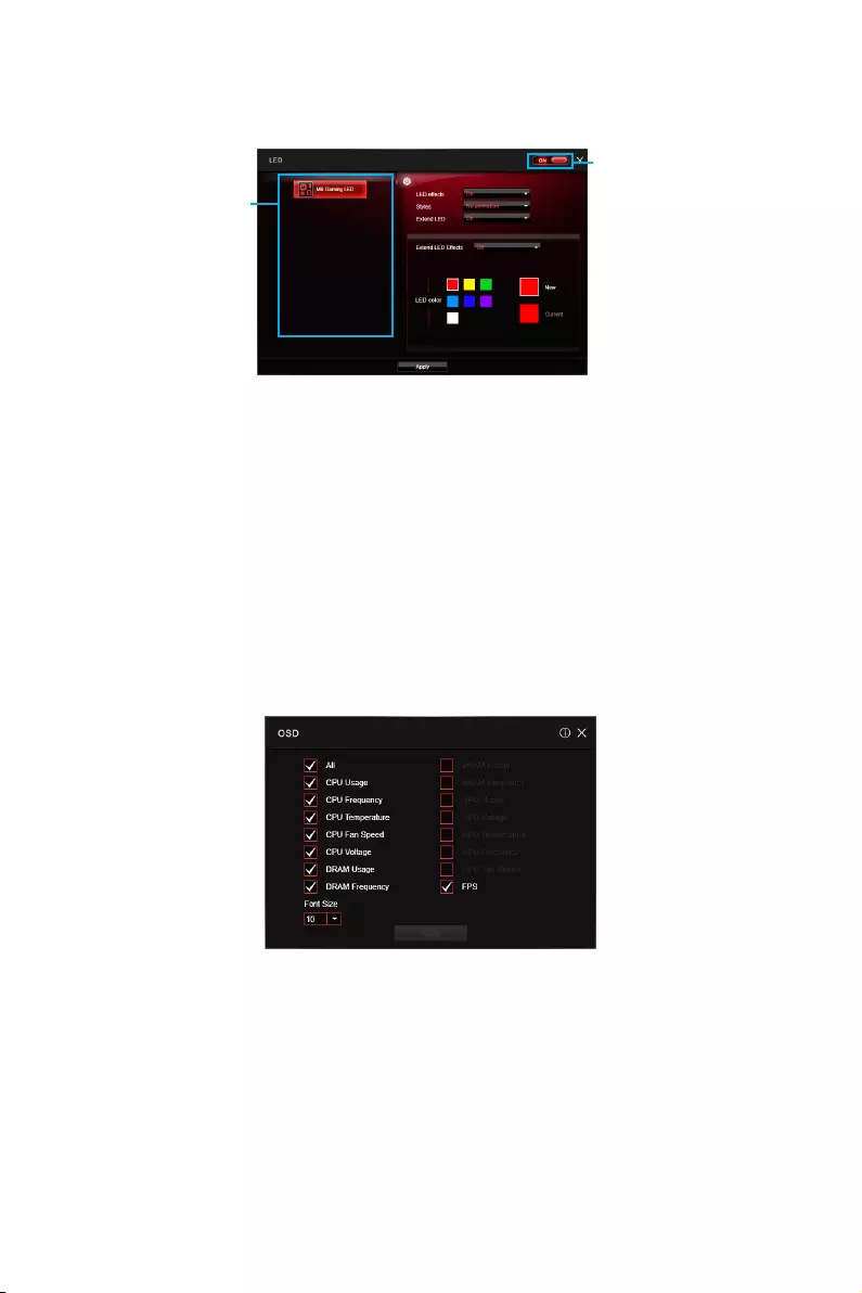
69
Software Description
LED
LED function allows you to control LED lights on your motherboard.
LED Area
Selection
LED
ON/OFF
yLED ON/OFF — allows you to turn ON/ OFF the LED function.
yLED Area Selection — separately controls each segment of LEDs on your
motherboard and graphics cards.
yLED effects — switches LEDs on or off.
yStyles — select the LED style from the drop-down list.
yMusic (optional) — flashes the LED light with music’s beat.
yExtend LED (optional) — allows you to turn ON/ OFF the Extend LED Effects.
Extend LED Effects — select extend LED strip effect.
yLED color (optional) — allows you change the LED color.
yApply Button — applies above settings to LEDs.
OSD Setting Panel
Use the OSD setting panel to specify information within on-screen display (OSD).
yApply Button — applies above settings to OSD.
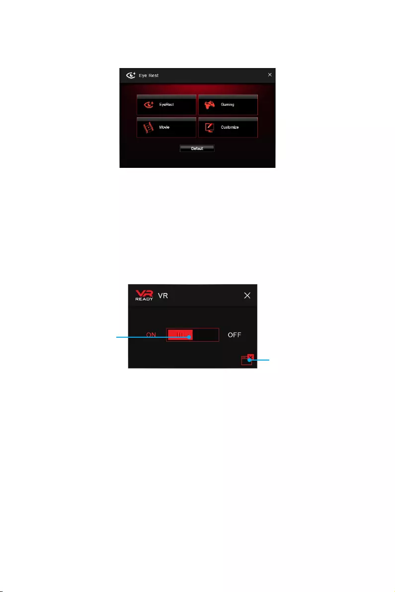
70 Software Description
Eye Rest
Eye Rest allows you to optimize the display on your monitor.
yEyeRest — reduces blue-light of your LED backlit screen, in order to protect your
eyes.
yGaming — automatically increases contrast ratio of your screen.
yMovie — automatically increases dynamic contrast ratio of your screen.
yCustomize — allows you to adjust gamma, contrast and color balance for your
screen.
yDefault — loads the default settings.
VR Ready
It will optimize the performance of your system to ensure everything is VR Ready.
Applications
VR ON/ OFF
yVR ON/ OFF -enables or disables VR settings.
yApplications — appears when you turn on the VR support. It allows you to close some
applications to optimize the system for better VR experience.
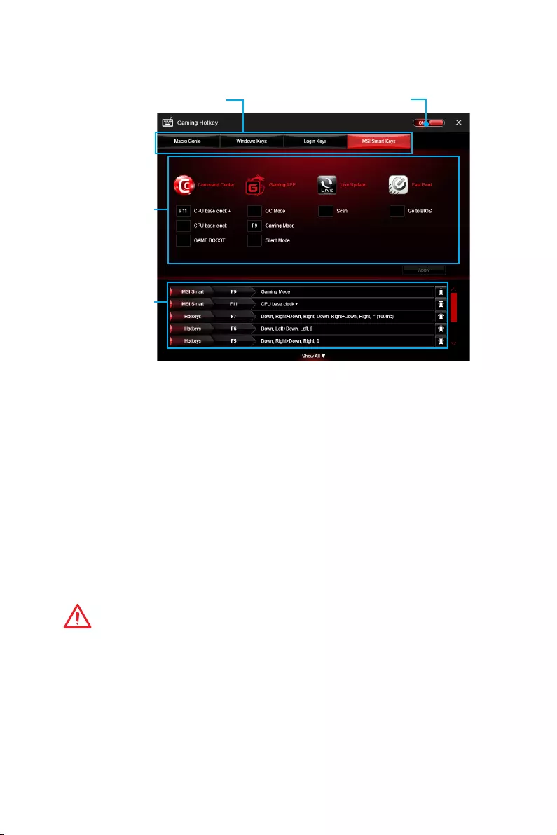
71
Software Description
Gaming Hotkey
Gaming Hotkey provides instant control of the system through user defined hotkeys.
Categories Toggle
Hotkey Manager
Current Hotkeys
Gaming Hotkey ON/OFF
yGaming Hotkey ON/OFF — allows you to turn ON/OFF the Gaming Hotkey function.
yCategories Toggle — allows you to toggle over the Hotkey categories.
Macro Genie — provides the keyboard and mouse macro record function and allows
you to define the hotkeys for the macro recorder.
1. Click on the Record button to start the keyboard and mouse macro recorder.
2. Click on the Stop button to stop the recorder.
3. Key-in a file name and set-up the parameter for the macro.
4. Finally, click on the Save button to save the recorded macro.
Windows Keys — allows you to define hotkeys to replace Windows default keyboard
shortcuts.
Login Keys — provides hotkey login function.
MSI Smart Keys — allows you to define hotkeys for MSI Smart Keys.
yHotkey Manager — allows you to create, edit and delete hotkeys.
yCurrent Hotkeys — shows all existing hotkeys.
Important
y
The Caps Lock, Num Lock, Scroll Lock, Window Home, Application and BackSpace
keys can not be used as Hotkeys.
y
Some key combinations are reserved for use by Microsoft Windows and can not be
assigned as a hotkey.

72 Software Description
Mouse Master
Mouse Master provides mouse macro function. You can also use it to change DPI of
your mouse.
Delay Time
Macro Hot Key DPI Hot Key
Test Area
Clear Button
Mouse Action
DPI Setting
Default Button
Action List
Edit Buttons
Load Button
Save Button
yDelay Time — allows you to apply a delay time in mouse macro.
yMacro Hot Key — allows you to assign a hotkey from A to Z to activate the macro.
yMouse Action — assigns mouse actions to the macro.
New — captures the mouse coordinate and add to the macro.
Left — adds a left-click to the macro.
Middle — adds a middle-click to the macro.
Right — adds a right-click to the macro.
yAction List — shows the actions of the current macro.
yEdit Buttons — there 3 buttons for editing the macro.
Run — activates the macro.
Delete — removes the selected action from the macro.
Clear — removes all actions from the macro.
yLoad Button — allows you to load a macro.
ySave Button — allows you to save the macro to a file.
yDPI Setting — allows you select the mouse DPI from the drop-down menu.
yDefault Button — reverts to the default DPI setting.
yDPI Hot Key — allows you to assign a hotkey from A to Z to activate the DPI setting.
Please note that you must hold the hotkey to keep the DPI setting. When you release
the hotkey, the DPI setting will be reverted to default.
yTest Area — allows you to test the mouse movement.
yClear Button — clears the test area.
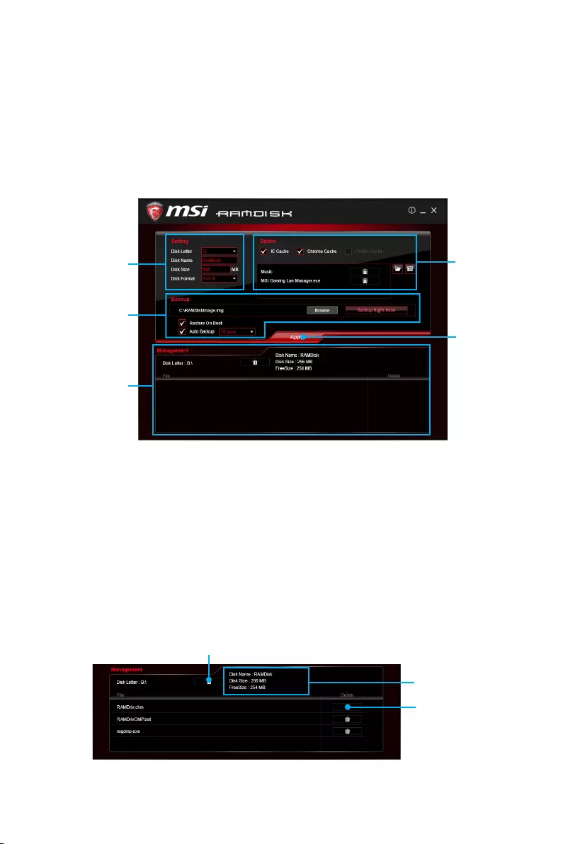
73
Software Description
RAMDISK
RAMDISK creates a virtual RAM drive using the available memory in your computer,
the performance of the RAMDISK is faster than an SSD and hard drive. RAMDISK
allows you to store any temporary information on it. Furthermore, using the RAMDISK
will extend your SSD’s life by sparing it from excessive reading and writing.
Creating a RAM Disk
When RAMDISK is started, it will create a default RAM disk. If you want to change
settings, refer to following instructions.
Setting
Backup
Management
Option
Apply
Button
ySetting — specify Letter, Name, Size and Format of the RAM disk.
yOption — select browser temporary files to save/load on the RAM disk. You can also
add software files to improve reading speed.
yBackup — specify backup and restore settings to prevent data loss. All files will be
lost each time the RAMDISK is stopped if you do not backup.
Browse Button — set the path to the image file.
Backup Right Now Button — manually backup files.
Restore On Boot — check this box to have the image file loaded automatically when
RAMDISK starts.
Auto Backup — check this box to backup automatically over a period of time.
yApply Button — allows you to apply changes.
yManagement — shows RAMDISK information and allows you to delete files.
Dislpay
information
Delete files
in the RAM
disk.
Remove the RAM disk
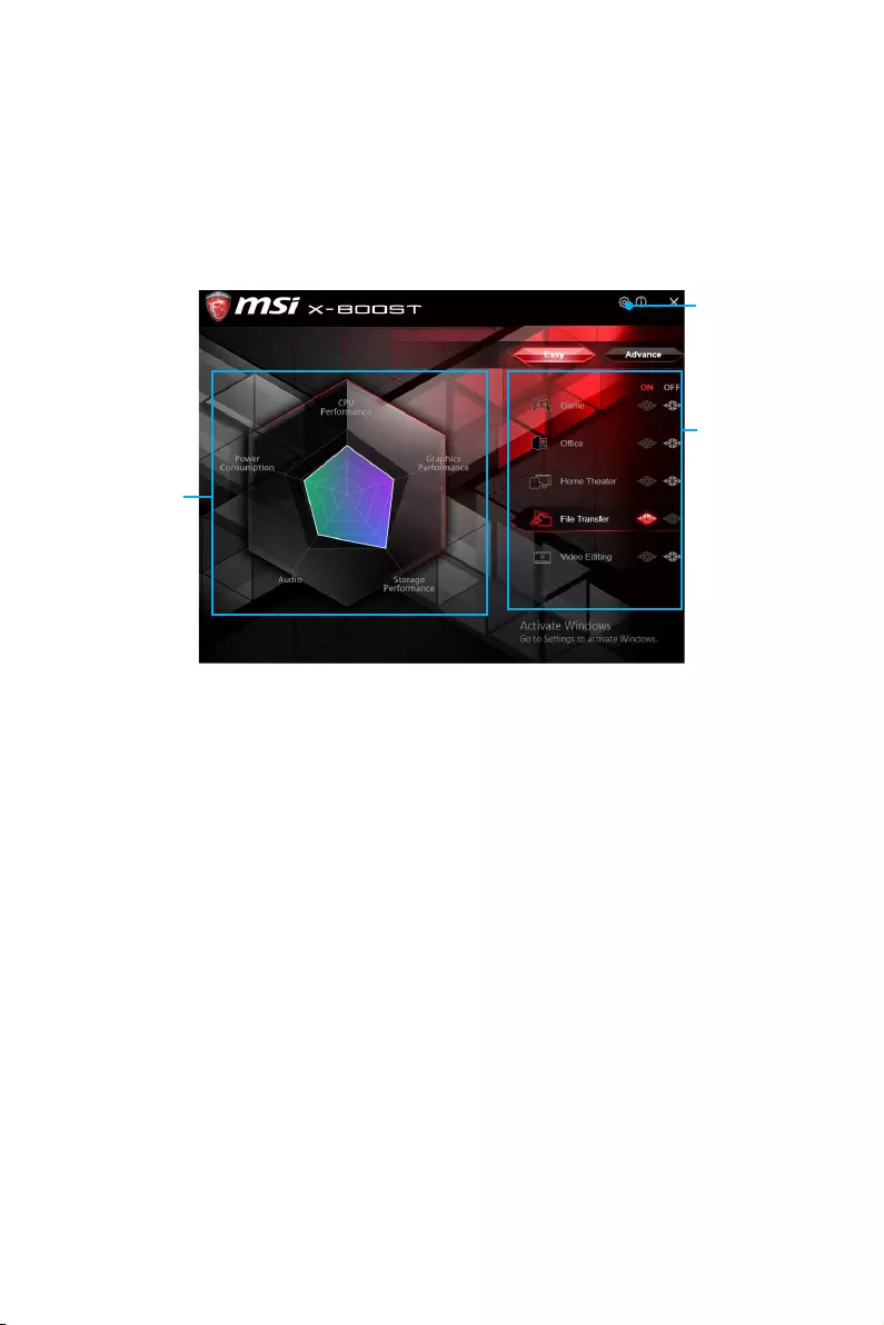
74 Software Description
X-BOOST
The MSI X-BOOST allows you to select the system performance mode to meet your
current system environment or supports faster storage access speed. Most of the
external storage and memory cards can also benefit this feature.
Easy
In Easy page, you can select one system performance mode to meet the current
system environment.
Setting
Performance
information
Performance
mode
yPerformance mode — moves over the mouse to any one of performance mode and
click on the ON button to enable it.
yPerformance information — displays the system performance diagram of enabled
mode.
ySetting — enables or disables Run X-BOOST when windows starts.
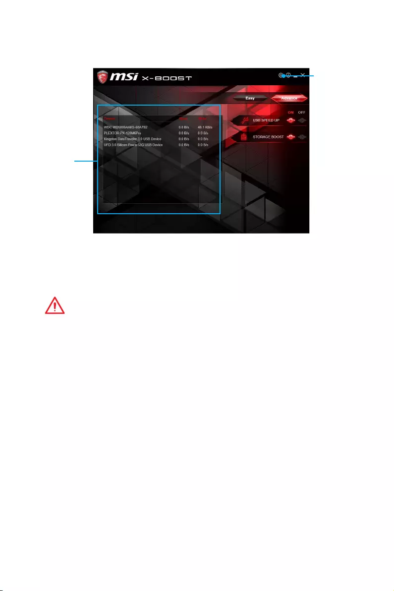
75
Software Description
Advance
In Advance page, you can enable the USB SPEED UP and/or the STORAGE BOOST.
Setting
Device
information
yDevice information — displays the information and current transfer rates/ access
spepds of USB/ storage devices.
ySetting — enables or disables Run X-BOOST when windows starts.
yUSB SPEED UP — supports faster data transfer rates of the USB storage devices.
ySTORAGE BOOST — supports faster access speed of storage device.
Important
y
Please note that you can only select one mode at a time from Easy or Advance page
as MSI X-BOOST function.
y
The improved transfer rate/ access speed will vary with the USB/ storage device.
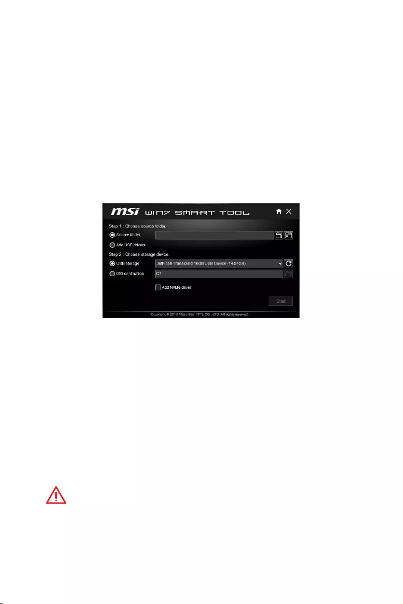
76 Software Description
MSI SMART TOOL
MSI SMART TOOL is a convenient tool that can help you to create your Windows
installation USB flash drive with USB 3.0 drivers, and it can also create a SUPER RAID.
Main menu
After installing and activating MSI SMART TOOL, it will display a main menu for you to
choose Win7 Smart Tool or SUPER RAID. Note that the SUPER RAID is only available
when your system equipped with at least 3 hard-disk drives (1 system disk and 2 data
disks).
WIN7 SMART TOOL
Before you can create your Windows installation USB flash drive, you’ll need to have
your Windows Installation DVD or ISO file, and also have a minimum of a 8GB USB
flash drive to create your installer. Be sure to backup files on the USB drive, this
process will erase it.
To create the Windows installation USB drive:
Step1. Choose source folder
yIn the Source folder box, type the name and path of your Windows ISO file, or click
Browse button and select the file from the dialog box. (This option will copy all
Windows installation files and USB 3.0 drivers)
yIf you already have the Windows Installation USB flash drive and just want to add
USB 3.0 drivers on it, you can choose Add USB drivers.
Step2. Choose Storage device
yChoose USB storage and select your USB flash drive in the drop-down list. In case
the USB flash drive is not listed, click the Refresh Drive button.
yIf you want to install Windows on the NVMe SSD, check the Add NVMe driver
checkbox to copy NVMe drivers to the USB flash drive.
yClick Start.
Important
You can also create an installer ISO image file by selecting the ISO destination in
Step2, and then burn it onto the DVD.
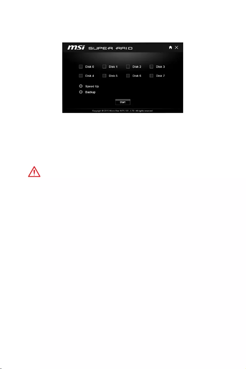
77
Software Description
SUPER RAID
This utility allows you to create a SUPER RAID in Windows system.
To create a SUPER RAID:
1. Use checkboxs to select the disks you want included in your RAID.
2. Choose Speed Up or Backup for RAID type.
ySpeed Up = RAID0
yBackup = RAID1
3. Click Start.
4. When prompt Finish!, click OK.
Important
SUPER RAID can’t includ the system disk.
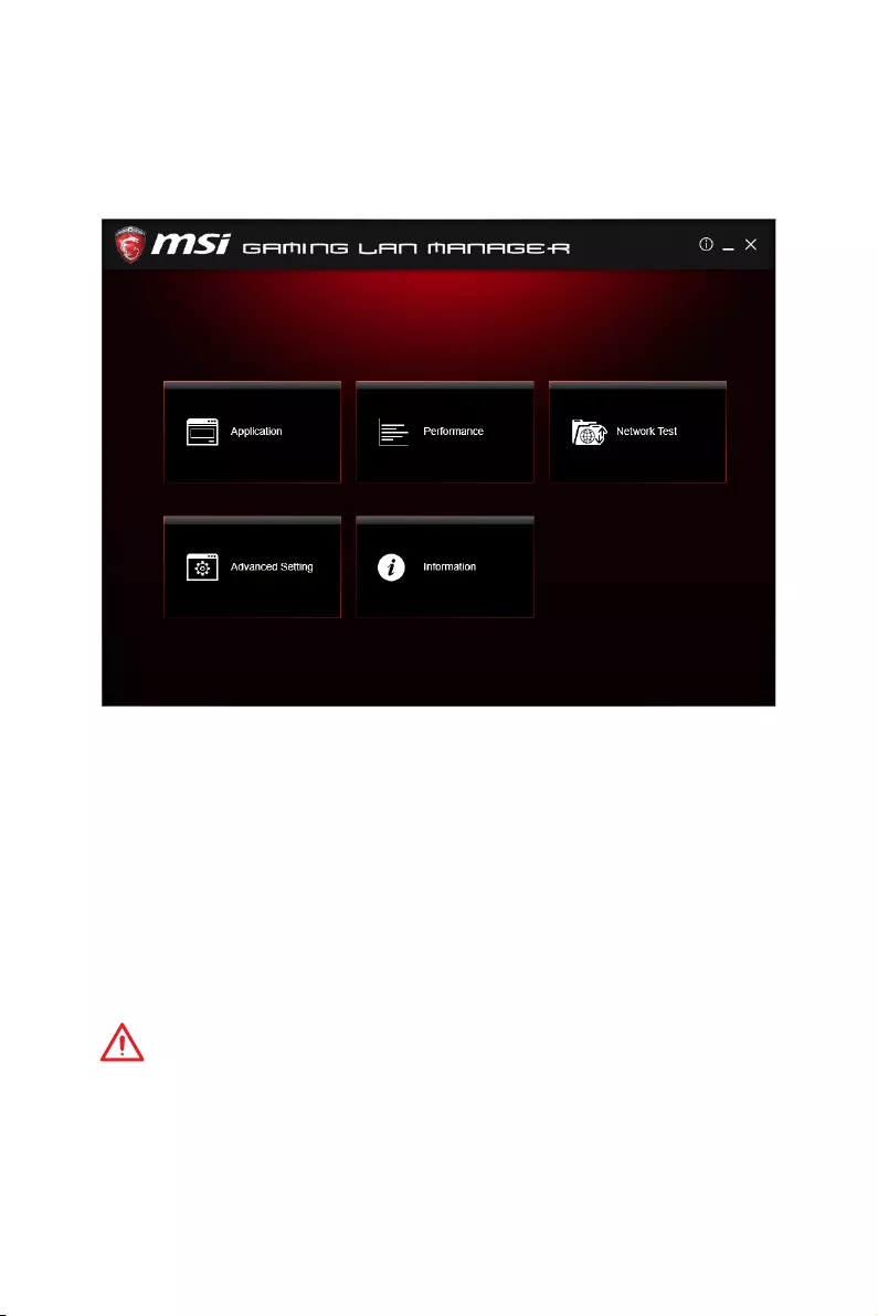
78 Software Description
GAMING LAN MANAGER
GAMING LAN MANAGER is an utility for traffic shaping for the Windows 7/ 10. It can
keep your internet fast during heavy upload/ download and improve your ping for
online games. If your motherboard has a Wi-Fi module, GAMING LAN MANAGER
provides virtual access point function for traffic shaping for your mobile devices.
yApplications — displays currently using network bandwidth applications. You can
prioritize Games, Medias or File sharing programs as high as possible.
yPerformance — shows top 5 applications by total traffic, allows you to monitor
network bandwidth usage.
yNetwork Test — allows you to setup bandwidth control.
yAdvanced Setting — allows you to expand RWIN to accelerate download speed. You
can also block IP address and setup virtual access point.
yInformation — shows version information.
Configuring Bandwidth
This section describes how to configure Internet Provider Speed. You can configure
default internet upload and download bandwidth from the Network Test tab on the
GAMING LAN MANAGER window.
Important
Before using the GAMING LAN MANAGER for the first time, you should use the
Test Network Speed button which runs a speed test of your current total Internet
bandwidth delivered through your Internet service provider.
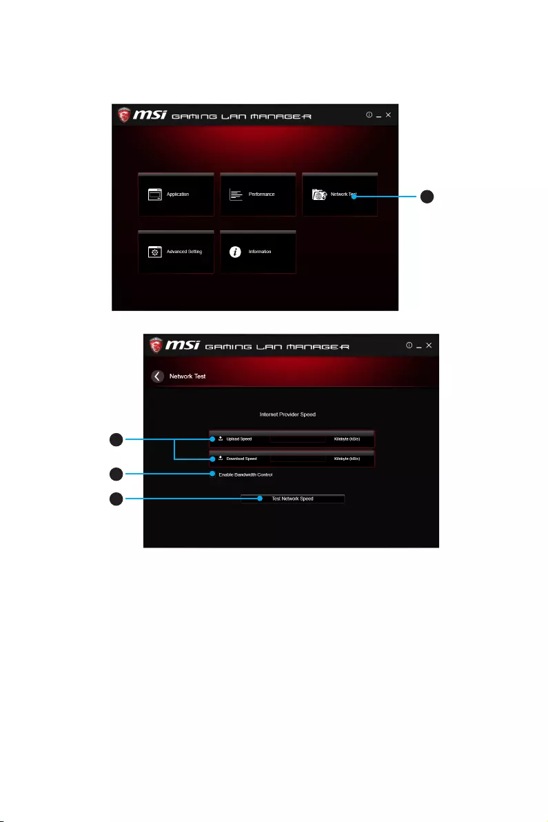
79
Software Description
Speed Testing
The speed testing is used to optimize bandwidth usage. To test the Upload and Down-
load speed, please follow the steps below:
1
1. Click the Network Test block in GAMING LAN MANAGER.
2
3
4
2. Click Test Network Speed button. The test takes several minutes to test your
network speed.
3. Enter the testing results into Upload Speed and Download Speed fields.
4. Check the Enable Bandwidth Control to allow the GAMING LAN MANAGER to
manage the bandwidth.
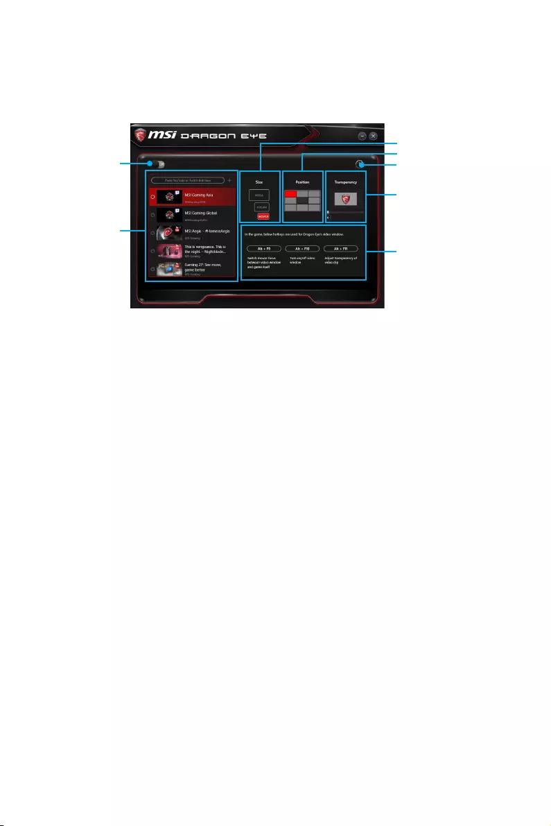
80 Software Description
DRAGON EYE
DRAGON EYE is an application allows you to watch a game guide, tutorial, live match
or tournament stream while playing a game. In the game, you can use hotkeys to
control / adjust the window of video.
Help
Size Settings
Position Settings
Transparency Settings
Hotkeys Information
On / Off Switch
Video List
yOn / Off Switch — enables or disables Dragon Eye during your gaming sessions.
Switch it on before you launch the game in order to watch video while playing.
yVideo List — allows you to select the video you want to watch, and also add videos or
channels to the list. You simply paste the URL of your video or stream into the input
bar and hit the +. Then your video or stream will be in the list and you can select it to
view it with Dragon Eye.
ySize Settings — allows you to select the size of the Dragon Eye video content
displayed on-screen when you’re playing a game. There are three options available:
WQVGA (Small – 400×240)
HVGAW (Medium – 640×360)
WVGA (Large – 768×480)
yPosition Settings — allows you to select where the Dragon Eye video needs to be
displayed on screen. This way you can control where you want your video in-game,
so you can place it on a place where no important game information is.
yHelp — If you want to watch the video tutorial for Dragon Eye or want to see if your
game is supported, press this button and the help window will be shown.
yTransparency Settings — allows you to set the transparency of your Dragon Eye
video.
0 = opaque | 100 = transparent.
yHotkeys Information — In this information screen you can find the hotkeys for
Dragon Eye. There are three hotkeys:
Alt+F9 — switches mouse focus between video window and game itself. (Direct
interface to adjust progress bar, volume and other settings of video during the
game)
Alt+F10 — turns on/off video window .
Alt+F11 — adjusts transparency of video clip.
NOTE: To customize hotkey, simply select the hotkey icon and then press the keys
combination you want to use as a hotkey.
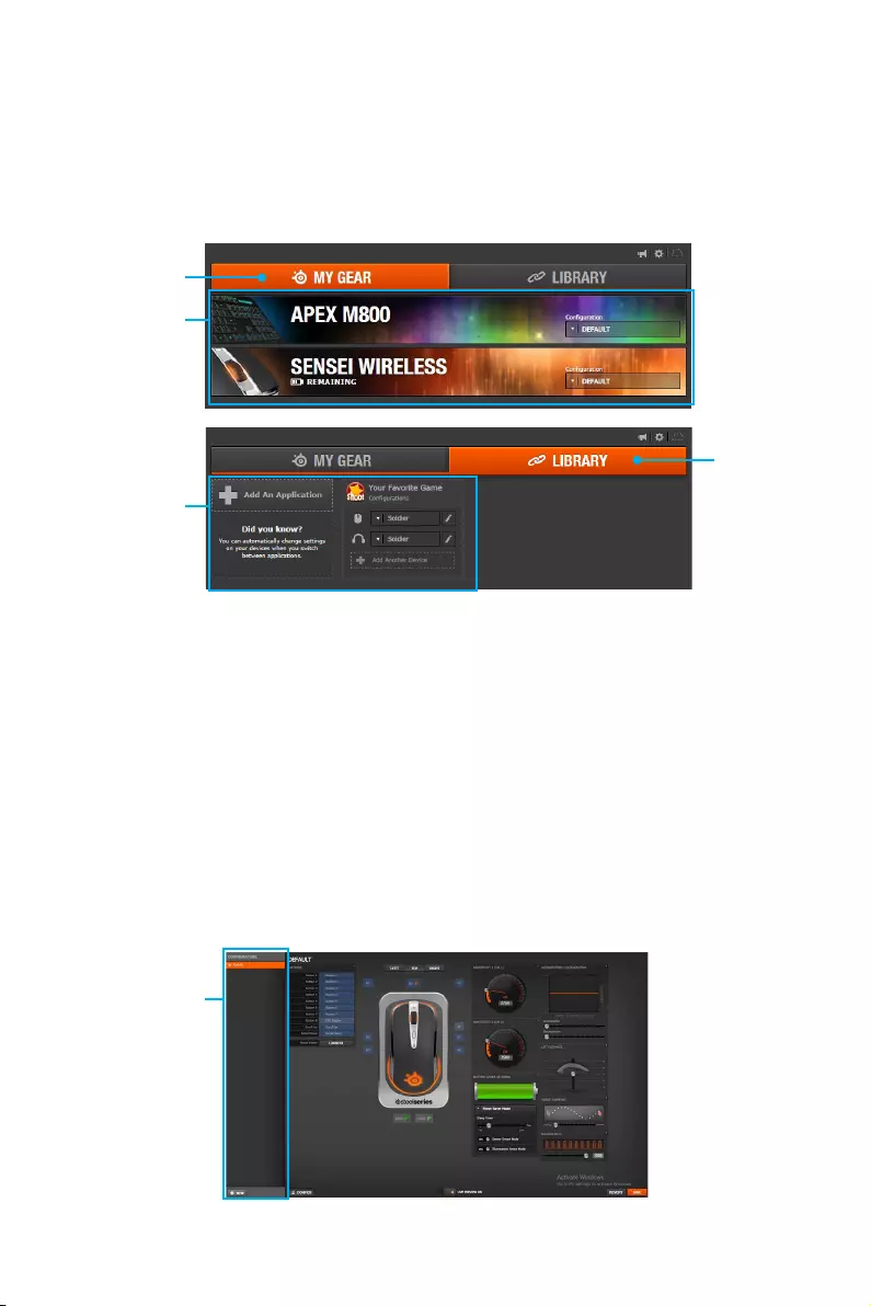
81
Software Description
SteelSeries Engine 3
SteelSeries Engine 3 is a unified platform built to support all of SteelSeries products.
It can deploy your saved device settings automatically when switching between your
favorite games or applications.
After installation the SteelSeries Engine background processes will start and the
interface will open automatically.
My Gear
Library
Device Cards
Application
Configuration
yMy Gear — all of your SteelSeries devices in one place.
Device Cards — all of your SteelSeries devices are easily accessible from the My
Gear tab, regardless of type, connection status, or which applications they are
assigned to.
yLibrary — quickly set up your configurations to autolaunch with an application.
Application Configuration — you can choose to have configurations deploy
automatically whenever you use a specific game or application. Add any number
of applications to your library and SteelSeries Engine 3 will seamlessly change the
configurations of your devices as you switch between them.
Configuration Windows
Configuration Windows are unique to their devices and each of them includes a
collapsible Configuration List Panel of all the configurations for that device. You
can create a new configuration by selecting the New button at the bottom of the
Configuration List Panel.
Configuration
Windows

82 Software Description
Configuring Your Devices
You can custom configurations for SteelSeries devices in their Configuration Windows.
The top left displays the name of the configuration you are viewing, the body features
widgets for customizing various functions of the device, and at the bottom are Save/
Revert buttons, a Live Preview toggle, and a button to open/close the collapsible
Configuration List Panel.
Configuration Windows Toggle
Widgets ToggleWidgets Widgets
Live Preview Revert/ Save Button
yWidgets — allow you to customize a certain aspect of your device.
yWidgets Toggle — allows you to toggle Widgets .
yConfiguration Windows Toggle — allows you to toggle the Configuration Windows.
yLive Preview — gives you the full experience of your configuration’s look, feel, and
sound while you are editing it.
yRevert/ Save Button — configuration changes are not written to the database until
you select Save. This gives you freedom to experiment, knowing that you can select
Revert to undo changes.
Tool Tip
When you click the question mark next to a feature name on the panel, a tooltip will
show, describing the particular function of that item.
Question Mark
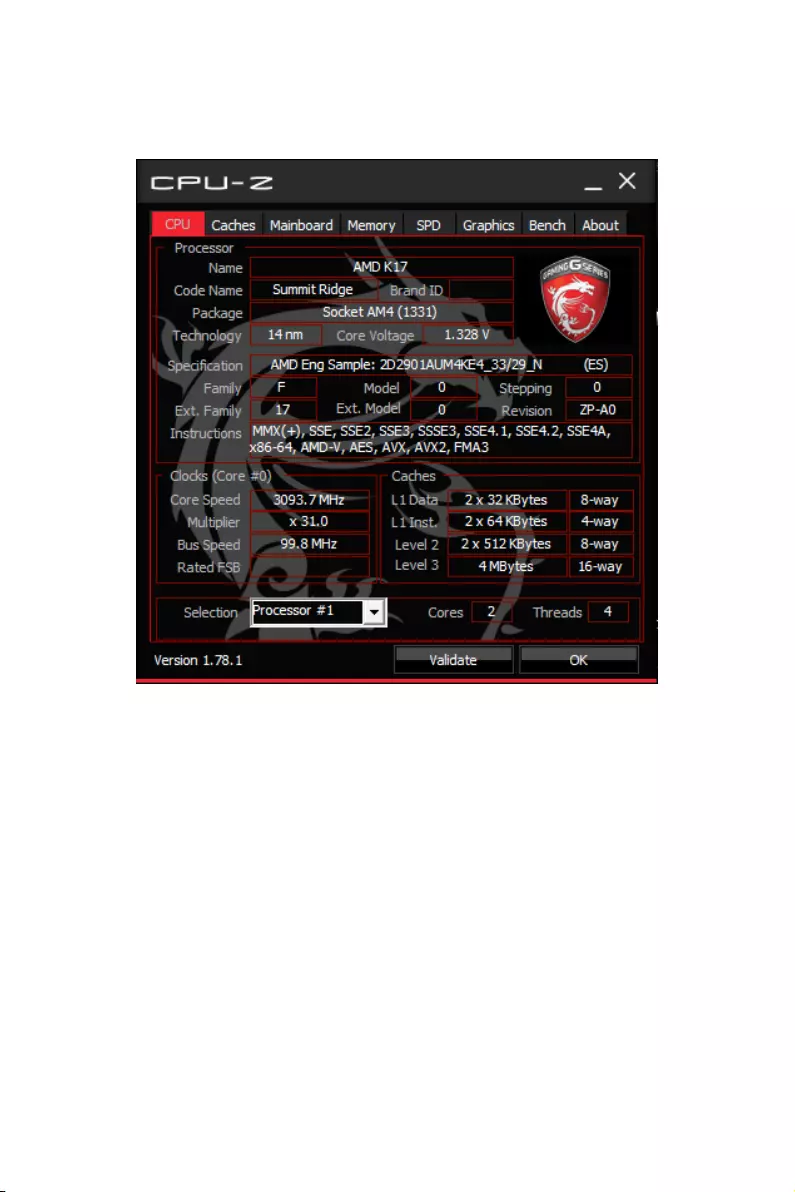
83
Software Description
CPU-Z
CPU-Z is an utility that gathers information on some of the main devices of your
system.
yCPU Tab — shows processor name, code name, package, specification, instructions
sets, core speed and cache levels.
yCaches Tab — shows extended information related to the cache capabilities.
yMainboard Tab — shows motherboard manufacturer, model name, chipset, BIOS
version and graphic interface.
yMemory Tab — shows memory type, memory size, channels, memory frequency.
ySPD Tab — shows specifications relating to each memory module connected to the
motherboard, including the size, type and frequency.
yGraphics Tab — shows GPU name, code name, core speed, memory size, and
memory type.
yBench Tab — allows you to run either a benchmark or a stress test on your processor.
yAbout Tab — shows the CPU-Z version, Windows version, DirectX version and allows
you to save the report file.

84 Troubleshooting
Troubleshooting
Before sending the motherboard for RMA
repair, try to go over troubleshooting
guide first to see if your got similar
symptoms as mentioned below.
The power is not on.
yConnect the AC power cord to an
electrical outlet securely.
yCheck if all ATX power connectors
like ATX_PWR1, CPU_PWR1 are
connected from the power supply to
the motherboard?
ySome power supply units have a power
button on the rear side, make sure the
button is turned on.
yCheck if the power switch cable is
connected to JFP1 pin header properly.
yVerify the Clear CMOS jumper JBAT1 is
set to Keep DATA.
yTest with another known working
power supply of equal or greater
wattage.
The power is on, but no signal to
monitor
yConnect the monitor power cord to a
electrical outlet securely.
yMake sure the monitor is turned on.
ySelect different inputs on the monitor.
yIf 3 long beeps are heard, remove all
memory modules and try to install only
one memory module in the DIMMA2
slot first and then restart the computer.
yIf 1 long 2 short beeps are heard,
remove and reinstall the graphics card
and then restart the computer.
yTest with another known working
graphics card.
The computer does not boot after
updating the BIOS
yClear the CMOS.
yUse the secondary BIOS to bootup the
system (Only for motherboard with
Dual BIOS)
Lost BIOS password
yClear the CMOS, but that will cause
you to lose all customized settings in
the BIOS.
There is no audio
yAdjust the volume.
yConnect the speakers/headphones to
audio ports on the motherboard rear
IO panel.
yRemove secondary speakers/
headphones, HDMI cables, USB audio
devices.
yTest with another known working
speaker or headphone.
There is no network
yMake sure the network chipset driver
has been installed.
yVerify if the network cable is properly
connected and make sure the LAN port
LEDs are properly illuminated.
yVerify your TCP/IP settings.
yRestart or reset your router.
yTest with another known working LAN
cable.
The USB device is not working
yMake sure your USB drive driver has
been installed.
yVerify if USB device is listed in
Windows® Device Manager.
yConnect the USB device to other USB
port on the motherboard rear IO panel.
85
Regulatory Notices
FCC Compliance Statement
Note: This equipment has been tested and found to
comply with the limits for a Class B digital device,
pursuant to part 15 of the FCC Rules. These limits
are designed to provide reasonable protection against
harmful interference in a residential installation. This
equipment generates, uses and can radiate radio
frequency energy and, if not installed and used in
accordance with the instructions, may cause harmful
interference to radio communications. However, there
is no guarantee that interference will not occur in a
particular installation. If this equipment does cause
harmful interference to radio or television reception,
which can be determined by turning the equipment
off and on, the user is encouraged to try to correct the
interference by one or more of the following measures:
yReorient or relocate the receiving antenna.
yIncrease the separation between the equipment
and receiver.
yConnect the equipment into an outlet on a circuit
different from that to which the receiver is
connected.
yConsult the dealer or an experienced radio/TV
technician for help.
Caution: Changes or modifications not expressly
approved by the party responsible for compliance could
void the user’s authority to operate the equipment.
Tested to comply with FCC standards
FOR HOME OR OFFICE USE
This device complies with part 15 of the FCC Rules.
Operation is subject to the following two conditions:
(1) This device may not cause harmful interference, and
(2) this device must accept any interference received,
including interference that may cause undesired
operation.
CE Conformity
Hereby, Micro-Star International CO., LTD
declares that this device is in compliance
with the essential safety requirements and
other relevant provisions set out in the European
Directive.
C-Tick Compliance
B급 기기 (가정용 방송통신기자재)
이 기기는 가정용(B급) 전자파적합기기로서 주
로 가정에서 사용하는 것을 목적으로 하며, 모
든 지역에서 사용할 수 있습니다.
クラスB情報技術装置
この装置は、クラスB情報技術装置です。この
装置は、家庭環境で使用することを目的として
い ま す が、こ の 装 置 が ラ ジ オ や テ レ ビ ジ ョ ン 受
信機に近接して使用されると、受信障害を引き起こすこと
があります。取扱説明書に従って
正しい取り扱いをして下さい
VCCI-B
Battery Information
European Union:
Batteries, battery packs, and
accumulators should not be disposed of as
unsorted household waste. Please use the
public collection system to return, recycle,
or treat them in compliance with the local
regulations.
Taiwan:
廢電池請回收
For better environmental protection, waste
batteries should be collected separately
for recycling or special disposal.
California, USA:
The button cell battery may contain
perchlorate material and requires special
handling when recycled or disposed of in
California.
For further information please visit:
http://www.dtsc.ca.gov/hazardouswaste/perchlorate/
CAUTION: There is a risk of explosion, if battery is
incorrectly replaced.
Replace only with the same or equivalent type
recommended by the manufacturer.
Chemical Substances Information
In compliance with chemical substances regulations,
such as the EU REACH Regulation (Regulation EC
No. 1907/2006 of the European Parliament and the
Council), MSI provides the information of chemical
substances in products at:
http://www.msi.com/html/popup/csr/evmtprtt_pcm.
html
Regulatory Notices

86 Regulatory Notices
WEEE (Waste Electrical and
Electronic Equipment) Statement
ENGLISH
To protect the global environment and as
an environmentalist, MSI must remind
you that…
Under the European Union (“EU”)
Directive on Waste Electrical and
Electronic Equipment, Directive 2002/96/
EC, which takes effect on August 13,
2005, products of “electrical and electronic equipment”
cannot be discarded as municipal wastes anymore, and
manufacturers of covered electronic equipment will
be obligated to take back such products at the end of
their useful life. MSI will comply with the product take
back requirements at the end of life of MSI-branded
products that are sold into the EU. You can return these
products to local collection points.
DEUTSCH
Hinweis von MSI zur Erhaltung und Schutz unserer
Umwelt
Gemäß der Richtlinie 2002/96/EG über Elektro- und
Elektronik-Altgeräte dürfen Elektro- und Elektronik-
Altgeräte nicht mehr als kommunale Abfälle entsorgt
werden. MSI hat europaweit verschiedene Sammel-
und Recyclingunternehmen beauftragt, die in die
Europäische Union in Verkehr gebrachten Produkte,
am Ende seines Lebenszyklus zurückzunehmen.
Bitte entsorgen Sie dieses Produkt zum gegebenen
Zeitpunkt ausschliesslich an einer lokalen
Altgerätesammelstelle in Ihrer Nähe.
FRANÇAIS
En tant qu’écologiste et afin de protéger
l’environnement, MSI tient à rappeler ceci…
Au sujet de la directive européenne (EU) relative aux
déchets des équipement électriques et électroniques,
directive 2002/96/EC, prenant effet le 13 août 2005, que
les produits électriques et électroniques ne peuvent
être déposés dans les décharges ou tout simplement
mis à la poubelle. Les fabricants de ces équipements
seront obligés de récupérer certains produits en fin
de vie. MSI prendra en compte cette exigence relative
au retour des produits en fin de vie au sein de la
communauté européenne. Par conséquent vous pouvez
retourner localement ces matériels dans les points de
collecte.
РУССКИЙ
Компания MSI предпринимает активные действия
по защите окружающей среды, поэтому напоминаем
вам, что….
В соответствии с директивой Европейского
Союза (ЕС) по предотвращению загрязнения
окружающей среды использованным электрическим
и электронным оборудованием (директива
WEEE 2002/96/EC), вступающей в силу 13
августа 2005 года, изделия, относящиеся к
электрическому и электронному оборудованию,
не могут рассматриваться как бытовой мусор,
поэтому производители вышеперечисленного
электронного оборудования обязаны принимать
его для переработки по окончании срока службы.
MSI обязуется соблюдать требования по приему
продукции, проданной под маркой MSI на территории
EC, в переработку по окончании срока службы. Вы
можете вернуть эти изделия в специализированные
пункты приема.
ESPAÑOL
MSI como empresa comprometida con la protección
del medio ambiente, recomienda:
Bajo la directiva 2002/96/EC de la Unión Europea
en materia de desechos y/o equipos electrónicos,
con fecha de rigor desde el 13 de agosto de 2005,
los productos clasificados como “eléctricos y
equipos electrónicos” no pueden ser depositados
en los contenedores habituales de su municipio, los
fabricantes de equipos electrónicos, están obligados
a hacerse cargo de dichos productos al termino de
su período de vida. MSI estará comprometido con los
términos de recogida de sus productos vendidos en
la Unión Europea al final de su periodo de vida. Usted
debe depositar estos productos en el punto limpio
establecido por el ayuntamiento de su localidad o
entregar a una empresa autorizada para la recogida de
estos residuos.
NEDERLANDS
Om het milieu te beschermen, wil MSI u eraan
herinneren dat….
De richtlijn van de Europese Unie (EU) met betrekking
tot Vervuiling van Electrische en Electronische
producten (2002/96/EC), die op 13 Augustus 2005 in
zal gaan kunnen niet meer beschouwd worden als
vervuiling. Fabrikanten van dit soort producten worden
verplicht om producten retour te nemen aan het
eind van hun levenscyclus. MSI zal overeenkomstig
de richtlijn handelen voor de producten die de
merknaam MSI dragen en verkocht zijn in de EU. Deze
goederen kunnen geretourneerd worden op lokale
inzamelingspunten.
SRPSKI
Da bi zaštitili prirodnu sredinu, i kao preduzeće koje
vodi računa o okolini i prirodnoj sredini, MSI mora da
vas podesti da…
Po Direktivi Evropske unije (“EU”) o odbačenoj
ekektronskoj i električnoj opremi, Direktiva 2002/96/
EC, koja stupa na snagu od 13. Avgusta 2005, proizvodi
koji spadaju pod “elektronsku i električnu opremu”
ne mogu više biti odbačeni kao običan otpad i
proizvođači ove opreme biće prinuđeni da uzmu natrag
ove proizvode na kraju njihovog uobičajenog veka
trajanja. MSI će poštovati zahtev o preuzimanju ovakvih
proizvoda kojima je istekao vek trajanja, koji imaju MSI
oznaku i koji su prodati u EU. Ove proizvode možete
vratiti na lokalnim mestima za prikupljanje.
POLSKI
Aby chronić nasze środowisko naturalne oraz jako
firma dbająca o ekologię, MSI przypomina, że…
Zgodnie z Dyrektywą Unii Europejskiej (“UE”) dotyczącą
odpadów produktów elektrycznych i elektronicznych
(Dyrektywa 2002/96/EC), która wchodzi w życie 13
sierpnia 2005, tzw. “produkty oraz wyposażenie
elektryczne i elektroniczne “ nie mogą być traktowane
jako śmieci komunalne, tak więc producenci tych
produktów będą zobowiązani do odbierania ich w
momencie gdy produkt jest wycofywany z użycia.
MSI wypełni wymagania UE, przyjmując produkty
(sprzedawane na terenie Unii Europejskiej) wycofywane
z użycia. Produkty MSI będzie można zwracać w
wyznaczonych punktach zbiorczych.

87
Regulatory Notices
TÜRKÇE
Çevreci özelliğiyle bilinen MSI dünyada çevreyi
korumak için hatırlatır:
Avrupa Birliği (AB) Kararnamesi Elektrik ve Elektronik
Malzeme Atığı, 2002/96/EC Kararnamesi altında 13
Ağustos 2005 tarihinden itibaren geçerli olmak üzere,
elektrikli ve elektronik malzemeler diğer atıklar
gibi çöpe atılamayacak ve bu elektonik cihazların
üreticileri, cihazların kullanım süreleri bittikten sonra
ürünleri geri toplamakla yükümlü olacaktır. Avrupa
Birliği’ne satılan MSI markalı ürünlerin kullanım
süreleri bittiğinde MSI ürünlerin geri alınması isteği ile
işbirliği içerisinde olacaktır. Ürünlerinizi yerel toplama
noktalarına bırakabilirsiniz.
ČESKY
Záleží nám na ochraně životního prostředí — společnost
MSI upozorňuje…
Podle směrnice Evropské unie (“EU”) o likvidaci
elektrických a elektronických výrobků 2002/96/
EC platné od 13. srpna 2005 je zakázáno likvidovat
“elektrické a elektronické výrobky” v běžném
komunálním odpadu a výrobci elektronických
výrobků, na které se tato směrnice vztahuje, budou
povinni odebírat takové výrobky zpět po skončení
jejich životnosti. Společnost MSI splní požadavky na
odebírání výrobků značky MSI, prodávaných v zemích
EU, po skončení jejich životnosti. Tyto výrobky můžete
odevzdat v místních sběrnách.
MAGYAR
Annak érdekében, hogy környezetünket megvédjük,
illetve környezetvédőként fellépve az MSI emlékezteti
Önt, hogy …
Az Európai Unió („EU”) 2005. augusztus 13-án hatályba
lépő, az elektromos és elektronikus berendezések
hulladékairól szóló 2002/96/EK irányelve szerint
az elektromos és elektronikus berendezések
többé nem kezelhetőek lakossági hulladékként,
és az ilyen elektronikus berendezések gyártói
kötelessé válnak az ilyen termékek visszavételére
azok hasznos élettartama végén. Az MSI betartja a
termékvisszavétellel kapcsolatos követelményeket
az MSI márkanév alatt az EU-n belül értékesített
termékek esetében, azok élettartamának végén. Az
ilyen termékeket a legközelebbi gyűjtőhelyre viheti.
ITALIANO
Per proteggere l’ambiente, MSI, da sempre amica della
natura, ti ricorda che….
In base alla Direttiva dell’Unione Europea (EU) sullo
Smaltimento dei Materiali Elettrici ed Elettronici,
Direttiva 2002/96/EC in vigore dal 13 Agosto 2005,
prodotti appartenenti alla categoria dei Materiali
Elettrici ed Elettronici non possono più essere eliminati
come rifiuti municipali: i produttori di detti materiali
saranno obbligati a ritirare ogni prodotto alla fine
del suo ciclo di vita. MSI si adeguerà a tale Direttiva
ritirando tutti i prodotti marchiati MSI che sono stati
venduti all’interno dell’Unione Europea alla fine del
loro ciclo di vita. È possibile portare i prodotti nel più
vicino punto di raccolta
日本JIS C 0950材質宣言
日本工業規格JIS C 0950に よ り、2006年7月1日以降に販
売される特定分野の電気および電子機器について、製造
者による含有物質の表示が義務付けられます。
http://www.msi.com/html/popup/csr/cemm_jp.html
http://tw.msi.com/html/popup/csr_tw/cemm_jp.html
India RoHS
This product complies with the “India E-waste
(Management and Handling) Rule 2011” and
prohibits use of lead, mercury, hexavalent chromium,
polybrominated biphenyls or polybrominated diphenyl
ethers in concentrations exceeding 0.1 weight % and
0.01 weight % for cadmium, except for the exemptions
set in Schedule 2 of the Rule.
Türkiye EEE yönetmeli i
Türkiye Cumhuriyeti: EEE Yönetmeli ine Uygundur
Україна обмеження на наявність
небезпечних речовин
Обладнання відповідає вимогам Технічного
регламенту щодо обмеження використання
деяких небезпечних речовин в електричному та
електронному обладнані, затвердженого постановою
Кабінету Міністрів України від 3 грудня 2008 № 1057.
Việt Nam RoHS
Kể từ ngày 01/12/2012, tất cả các sản phẩm do công
ty MSI sản xuất tuân thủ Thông tư số 30/2011/TT-BCT
quy định tạm thời về giới hạn hàm lượng cho phép của
một số hóa chất độc hại có trong các sản phẩm điện,
điện tử”
Environmental Policy
yThe product has been designed to
enable proper reuse of parts and
recycling and should not be thrown
away at its end of life.
yUsers should contact the local
authorized point of collection for
recycling and disposing of their end-of-life products.
yVisit the MSI website and locate a nearby distributor
for further recycling information.
yUsers may also reach us at gpcontdev@msi.com for
information regarding proper Disposal, Take-back,
Recycling, and Disassembly of MSI products.
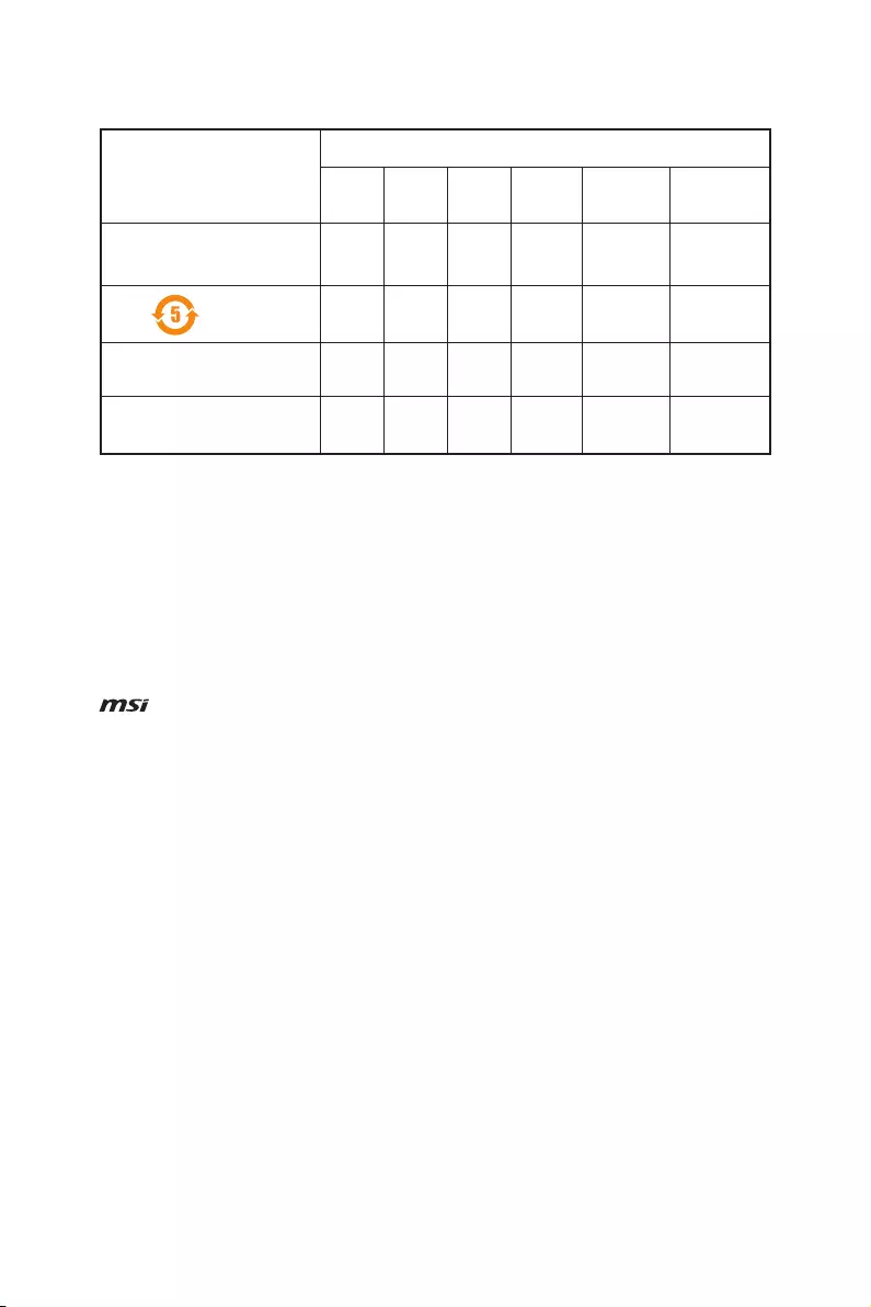
88 Regulatory Notices
产品中有害物质的名称及含量
部件名称
有害物质
铅
(Pb)
汞
(Hg)
镉
(Cd)
六价铬
(Cr(VI))
多溴联苯
(PBB)
多溴二苯醚
(PBDE)
印刷电路板组件* X O O O O O
电池** X O O O O O
外部信号连接头 X O O O O O
线材 X O O O O O
本表格依据 SJ/T 11364 的规定编制。
O: 表示该有害物质在该部件所有均质材料中的含量均在 GB/T 26572 规定的限量要求以下。
X: 表示该有害物质至少在该部件的某一均质材料中的含量超出 GB/T 26572 规定的限量要求,但所有部件都符合欧盟
RoHS要 求。
* 印刷电路板组件: 包括印刷电路板及其构成的零部件。
** 电池本体上如有环保使用期限标识,以本体标识为主。
■ 上述有毒有害物质或元素清单会依型号之部件差异而有所增减。
■ 產品部件本体上如有环保使用期限标识,以本体标识为主。
Copyright
Micro-Star Int’l Co.,Ltd.
Copyright © 2017 All rights reserved.
The material in this document is the intellectual
property of Micro-Star Int’l Co.,Ltd. We take every care
in the preparation of this document, but no guarantee
is given as to the correctness of its contents. Our
products are under continual improvement and we
reserve the right to make changes without notice.
Technical Support
If a problem arises with your system and no solution
can be obtained from the user guide, please
contact your place of purchase or local distributor.
Alternatively, please try the following help resources
for further guidance.
yVisit the MSI website for technical guide, BIOS
updates, driver updates, and other information:
http://www.msi.com
yRegister your product at: http://register.msi.com
Trademark Recognition
All product names used in this manual are the
properties of their respective owners and are
acknowledged.
Revision History
Version 3.0, 2017/03, For X370 GAMING PLUS
Описание
Характеристики
Технические характеристики материнской платы MSI H370 Gaming Plus
Socket
LGA1151
LGA1151
смотреть в других:
Поддерживаемые процессоры
Intel Core 8th Generation
Чипсет
Intel H370
Intel H370
смотреть в других:
Тип памяти
DDR4 DIMM
DDR4 DIMM
смотреть в других:
Частота памяти
2133 — 2666 МГц
Поддержка двухканального режима
есть
Максимальный объем памяти
Поддержка SLI/CrossFire
CrossFire X
CrossFire X
смотреть в других:
Тип слотов M.2
Key M, 2242/2260/2280/22110
Ethernet
1000 Мбит/с, на основе Intel I219V
Аудио контроллер
HDA, на основе Realtek ALC892
Основной разъем питания
24-pin
Разъем питания процессора
8-pin
Отзывы 6
Комментарии 0
Обзоры 0
Гарантия
Материнская плата MSI H370 Gaming Plus – цена, наличие, характеристики, отзывы и условия доставки по Москве и России.
Купить материнскую плату MSI H370 Gaming Plus можно на сайте KNS Москва заполнив форму заказа в корзине.
Для получения квалифицированной консультации о товаре звоните специалистам компании KNS Москва или задайте вопрос в чате.
Встроенные индикаторы
Индикаторы отладки EZ
Данные светодиоды показывают состояния отладки материнской платы.
Индикаторы DIMM
Данные светодиоды показывают установленные модуля памяти.
Индикатор GPU
Данный индикатор указывает на то, что встроенная графика процессора не
обнаружена и необходимо установить графическую карту.
Индикаторы слота PCIe x16
Данные LED светодиоды показывают режим работы слотов PCIe x16.
CPU — процессор не обнаружен или поврежден.
DRAM — память DRAM не обнаружена или
повреждена.
VGA — видеокарта не обнаружена или
повреждена.
BOOT — устройство загрузки не обнаружено или
повреждено.
Индикаторы DIMM
Индикатор GPU
Цвет LED
Красный
Белый
PCI_E2 LED
PCI_E4 LED
PCI_E6 LED
Режим работы
слота PCIe
x16
x8, x4, x1
Встроенные индикаторы
27
Код40209

<span>Продано.</span> Подобрать замену?
Материнская плата MSI — H370 GAMING PLUS, ATX, Intel H370, 1xLGA 1151v2, 4xDDR4 до 64ГБ, 1x1GbE, audio, intel optane memory, M.2, DVI-D, DP, 1xPS/2, 5xSATA, 6xUSB2.0, 7xUSB3.1, 1xUSB3.1 Type C, H370 GAMING PLUS
Авторизованный партнер MSI
Увеличить
- Описание
- Характеристики
- Отзывы
- Оплата и доставка
- Документы
- Задать вопрос
Материнская плата для ПК MSI H370 GAMING PLUS на базе чипсета Intel H370 поддерживает установку 1 процессора с разъемом LGA 1151v2, возможно установить 4 модуля памяти DIMM DDR4 общим объемом до 64ГБ, выполнена в форм-факторе ATX.
Сокет процессора
LGA 1151v2
Максимально памяти (ГБ)
64ГБ
Скорость сетевых портов
1 Гб/с
Поддержка Intel Optane Memory
да
Ширина упаковки (мм)
270мм
Позиционирование
Для компьютера
Достоинства
Удобный, доступный, понятный биос. Шикарная подсветка, и дизайн платы. Хорошее охлаждение. Высокие частоты работы оперативной памяти. Высокое качество.
Комментарий
Как и другая продукция мси радует своим качеством. Лучшая материнка среди конкурентов
Для меня было удивлением заметить увеличение производительности как и в играх так и вообще в быту при замене материнской платы Gigabyte GA-Z170-D3H на MSI H370.
1. Хотел бы выделить дополнительные утилиты для настройки конфигураций под себя, удобный интерфейс и широкий спектр настроек прекрасно помогают с этим.
2. Для любителей boosta через Bios, MSI приберегла удобный интерфейс и понятные объяснения для того что бы не накрутить чего лишнего.
Потому, легкая и удобная версия материнской платы подойдет для любых геймеров всех категорий, так и для людей которые думают на что именно надо заменить свою. Сам пользуюсь уже больше года продукцией MSI и каждый раз она радуют чем-то новым.
Достоинства
Оптимизация оперативной памяти(позволяет оперативке работать шустрее и лучшей при разгоне)
Внешний вид 10/10, не блеклый, но и не светит как знак бетмена на всю квартиру.
Поддержка процессоров 8-го поколения
Большое количество разъемов для кулеров
Поддержка ОЗУ до 2666MHz
DDR4 Boost: Дает прирост производительности памяти DDR4
Недостатки
Нет разъёмов HDMI или VGA. Зато есть DisplayPort и DVI-D. Это заставило покупать провод с DisplayPort на HDMI, чтобы вывести изображение на монитор.
BIOS поддерживает не все процессоры
Комментарий
Хорошая материнка за приемлемую цену
Достоинства
1.Материнская плата очень красиво смотрится в корпусе.
2. BIOS с масштабируемыми шрифтами высокого разрешения
3. Поддержка оперативной памяти DDR4 с частотой до 2666 МГц
4. Система подсветки Mystic Light очень солидно выглядит
Недостатки
Да вроде и нет!)
Комментарий
Если судить в общих чертах, то можно смело брать данный продукт.
Всегда останавливал свой взгляд на бренде MSI.
Недостатков мало, приятностей много !)
Советую брать пока не закончились) Лучше не найдете за такие деньги с такими достоинствами. Я долгое время пользуюсь продукцией MSI и она меня никогда не подводила, спасибо вам ребята за ваши чудесные новинки.
На мой взгляд лучшая плата этого года. Цена + качество + производительность на высшем уровне. Огромный респект компании MSI (вы большие молодцы) !
Достоинства
Дизайн
БИОС (по началу может пугать ,надо привыкнуть)
Фирменное ПО MSI , можно настраивать всё что угодно подсветку ,охлаждение и другое
Армированые разъемы
Недостатки
Хотелось бы звук по интересней
Комментарий
в целом хорошая мать за свои деньги , лишнего не чего нету . Единственное что хотелось бы более интересный звук , но если у вас есть звуковая карта то это не важно .
Достоинства
— Удобный BIOS (или же я привык)
— Простая и удобная софтина Msi Mystic Light. Настроил за пару минут подсветку, в трее не висит
— Поддержка ОЗУ до 2666MHz и с подсветкой
Недостатки
Общих недостатков нет. Не понравилась только настройка кулеров, но это можно пережить. Ну и цена достаточно высоковата
Комментарий
В общих чертах проблем не наблюдаю, все работает как часы. Всегда останавливал свой взгляд на бренде MSI. Мать как мать, без каких то недостатков или бросающихся в глаза достижений
Мы будем признательны, если вы оставите свой отзыв и поделитесь с пользователями опытом использования товара.
Мы работаем по полной или частичной онлайн предоплате. Доставляем товар в любую точку РФ. Доставка по Москве бесплатная при сумме заказа от 40 000 ₽, или 500 ₽, если сумма заказа меньше. Все цены указаны в рублях и включают НДС 20% (кроме некоторых лицензий на ПО).
Вы можете произвести оплату на сайте после оформления заказа и одобрения его менеджером следующими способами:
- Банковской картой (Visa, MasterCard, Maestro, МИР).
- Через Систему быстрых платежей (СБП) — по QR-коду в мобильном приложении банка.
- Банковским переводом для юр. и физ. лиц по выставленному счету.
Вся информация, опубликованная на сайте andpro.ru, в т.ч. цены товаров, описания, характеристики и комплектации не являются публичной офертой, определяемой положениями Статьи 437 Гражданского кодекса РФ и носят исключительно справочный характер. Договор оферты заключается только после подтверждения исполнения заказа сотрудником АНД-Системс или АНД-Софт.
Вы можете задать любой интересующий вас вопрос по товару или работе магазина.
Наши квалифицированные специалисты обязательно вам помогут.