
1
Quick Start
Quick Start
Thank you for purchasing the MSI® MAG Z690 TOMAHAWK WIFI/ MAG Z690 TORPEDO
motherboard. This Quick Start section provides demonstration diagrams about how
to install your computer. Some of the installations also provide video demonstrations.
Please link to the URL to watch it with the web browser on your phone or tablet. You
may have even link to the URL by scanning the QR code.
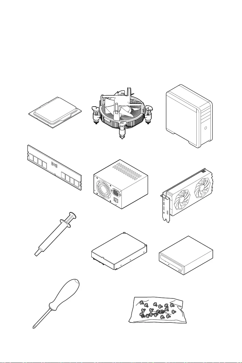
Preparing Tools and Components
Intel® LGA1700 CPU
LGA1700 CPU Fan
DDR5 Memory
Graphics Card
SATA Hard Disk Drive SATA DVD Drive
Phillips Screwdriver
Chassis
Power Supply Unit
A Package of Screws
Thermal Paste

2Quick Start
Safety Information
∙The components included in this package are prone to damage from electrostatic
discharge (ESD). Please adhere to the following instructions to ensure successful
computer assembly.
∙Ensure that all components are securely connected. Loose connections may cause
the computer to not recognize a component or fail to start.
∙Hold the motherboard by the edges to avoid touching sensitive components.
∙It is recommended to wear an electrostatic discharge (ESD) wrist strap when
handling the motherboard to prevent electrostatic damage. If an ESD wrist strap is
not available, discharge yourself of static electricity by touching another metal object
before handling the motherboard.
∙Store the motherboard in an electrostatic shielding container or on an anti-static
pad whenever the motherboard is not installed.
∙Before turning on the computer, ensure that there are no loose screws or metal
components on the motherboard or anywhere within the computer case.
∙Do not boot the computer before installation is completed. This could cause
permanent damage to the components as well as injury to the user.
∙If you need help during any installation step, please consult a certified computer
technician.
∙Always turn off the power supply and unplug the power cord from the power outlet
before installing or removing any computer component.
∙Keep this user guide for future reference.
∙Keep this motherboard away from humidity.
∙Make sure that your electrical outlet provides the same voltage as is indicated on
the PSU, before connecting the PSU to the electrical outlet.
∙Place the power cord such a way that people can not step on it. Do not place
anything over the power cord.
∙All cautions and warnings on the motherboard should be noted.
∙If any of the following situations arises, get the motherboard checked by service
personnel:
▪Liquid has penetrated into the computer.
▪The motherboard has been exposed to moisture.
▪The motherboard does not work well or you can not get it work according to user
guide.
▪The motherboard has been dropped and damaged.
▪The motherboard has obvious sign of breakage.
∙Do not leave this motherboard in an environment above 60°C (140°F), it may damage
the motherboard.
3
Quick Start
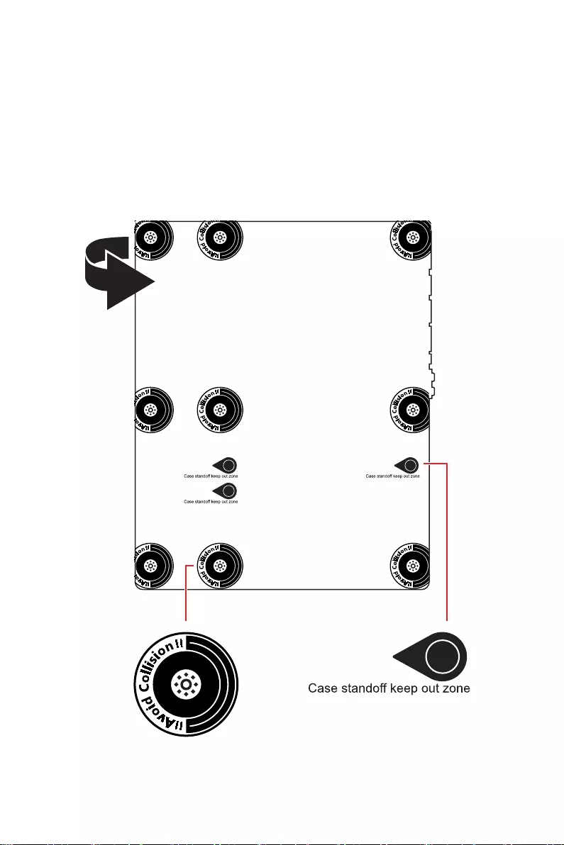
Case stand-off notification
To prevent damage to the motherboard, any unnecessary mounting stand-off between
the motherboard circuits and the computer case is prohibited. The Case standoff keep
out zone signs will be marked on the backside of motherboard (as shown below) to
serve as a warning to user.
Avoid collision notification
Protective paint is printed around each screw hole to prevent parts from being
scratched.
4Quick Start
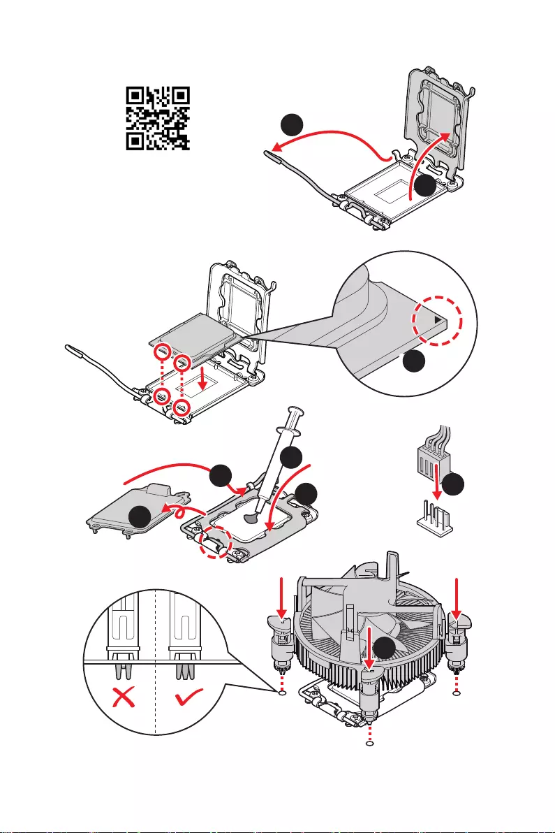
Installing a Processor
⚽
1
2
3
6
4
5
7
8
9
5
Quick Start
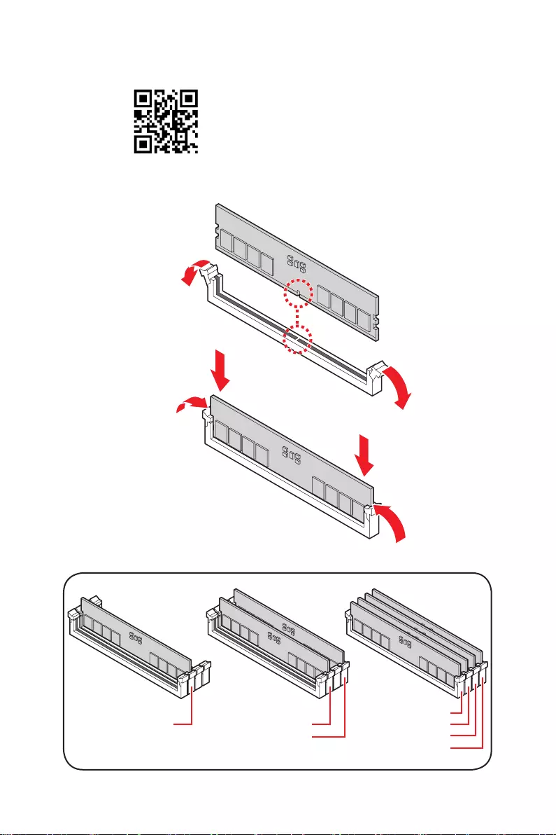
Installing DDR5 memory
DIMMA2 DIMMA2
DIMMB2
DIMMA1
DIMMA2
DIMMB1
DIMMB2
⚽
6Quick Start
HDD LED
RESET SW
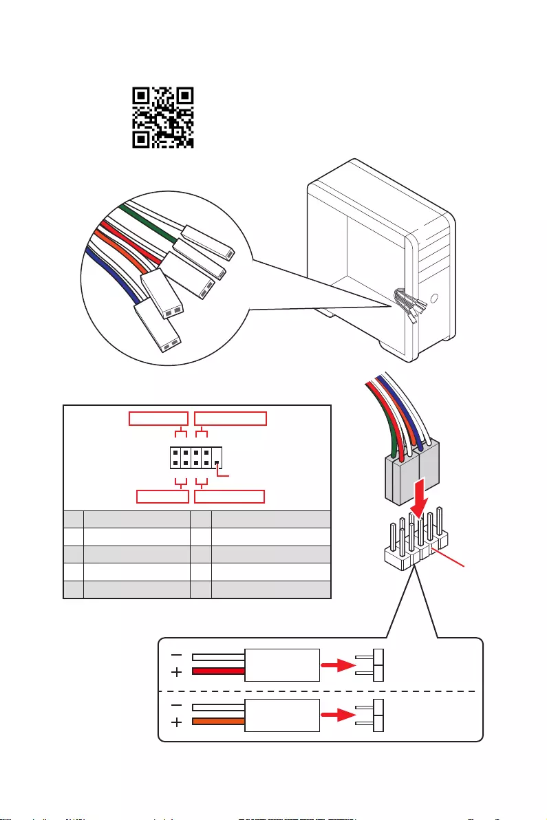
Connecting the Front Panel Header
JFP1
HDD LED HDD LED —
HDD LED +
POWER LED —
POWER LED +
POWER LED
1
2 10
9
+
+
+— ——
—
+
Power LED
HDD LED Reset Switch
Reserved
Power Switch
JFP1
1 HDD LED + 2 Power LED +
3 HDD LED — 4 Power LED —
5 Reset Switch 6 Power Switch
7 Reset Switch 8 Power Switch
9 Reserved 10 No Pin
RESET SW
POWER SW
POWER LED+
POWER LED-
HDD LED
⚽
7
Quick Start
BAT1
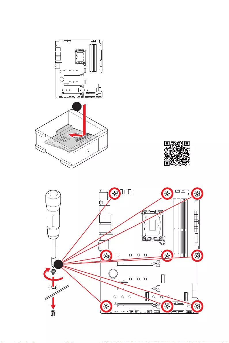
Installing the Motherboard
1
2
⚽
Torque:
3 kgf·cm*
*3 kgf·cm
= 0.3 N·m
= 2.6 lbf·in
8Quick Start
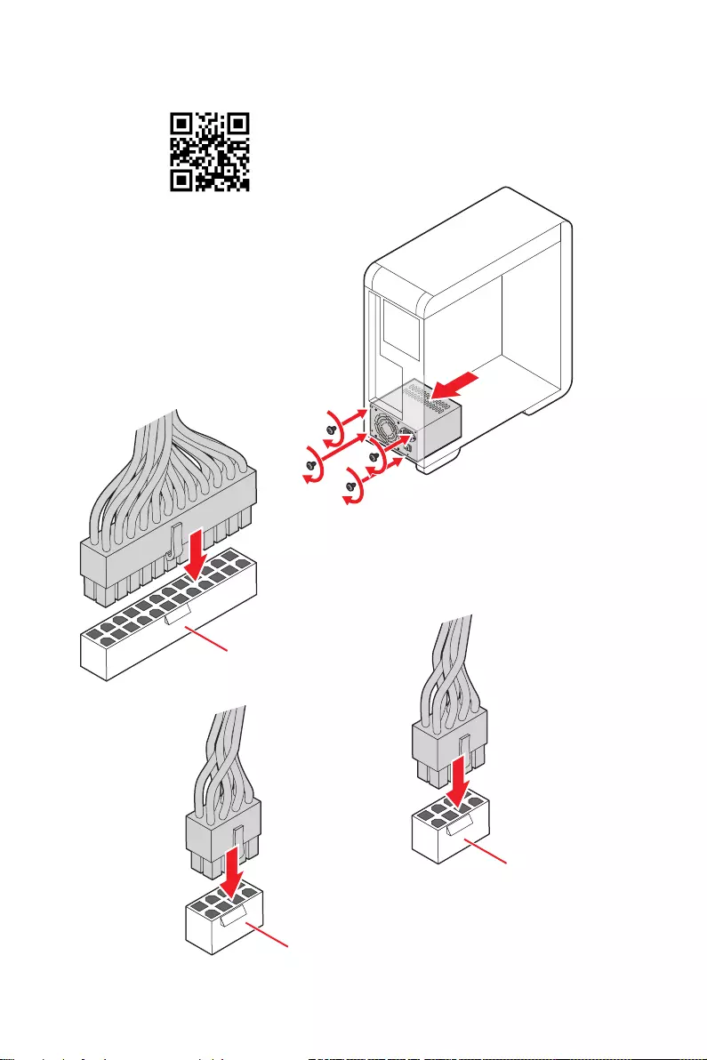
Connecting the Power Connectors
ATX_PWR1
CPU_PWR1
⚽
CPU_PWR2
9
Quick Start
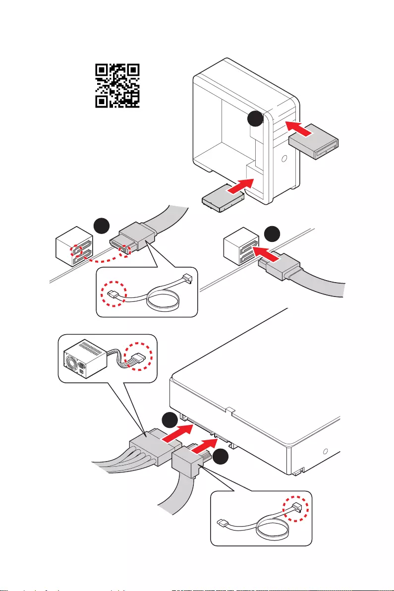
Installing SATA Drives
1
23
4
5
⚽
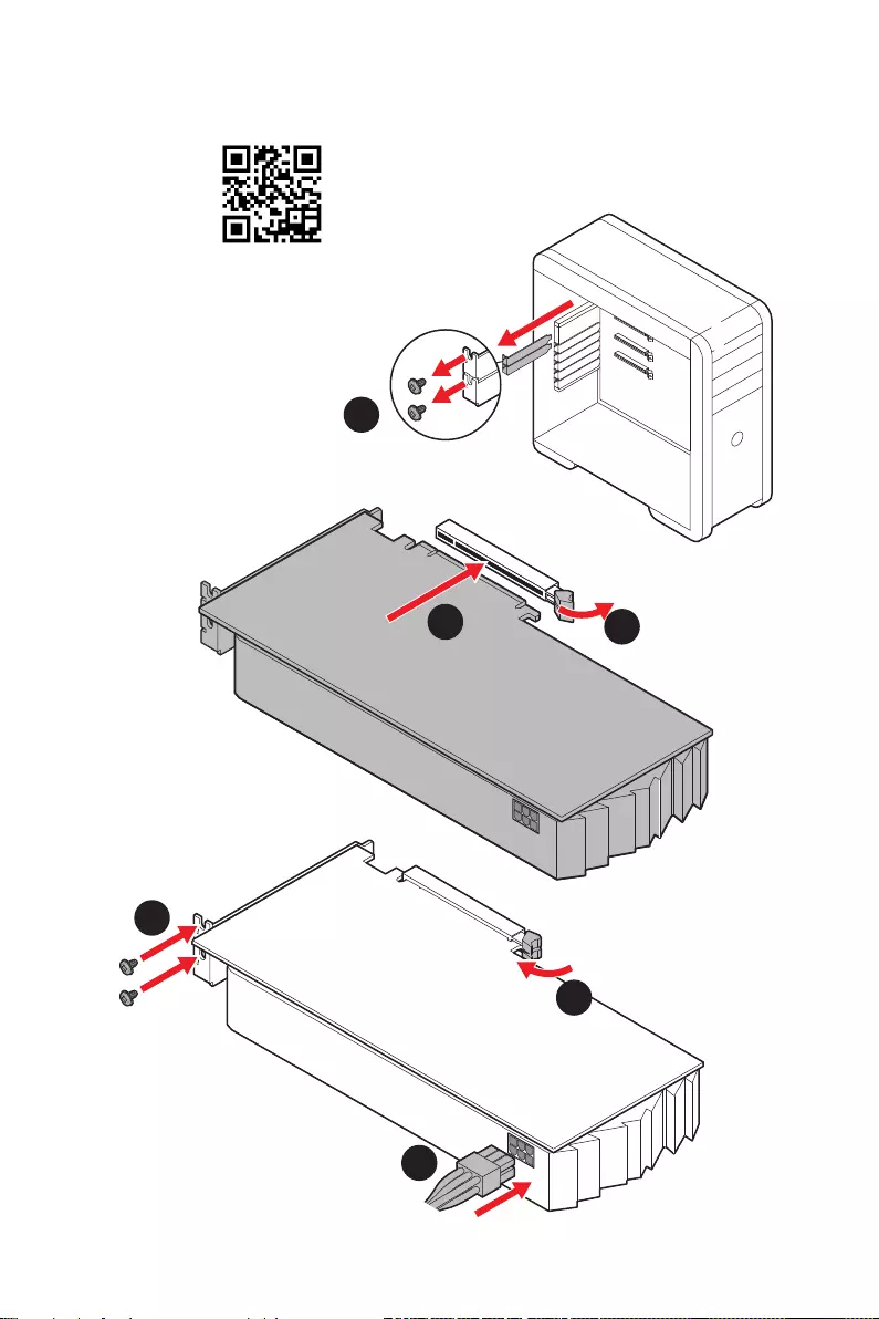
10 Quick Start
1
Installing a Graphics Card
2
3
4
5
6
⚽
11
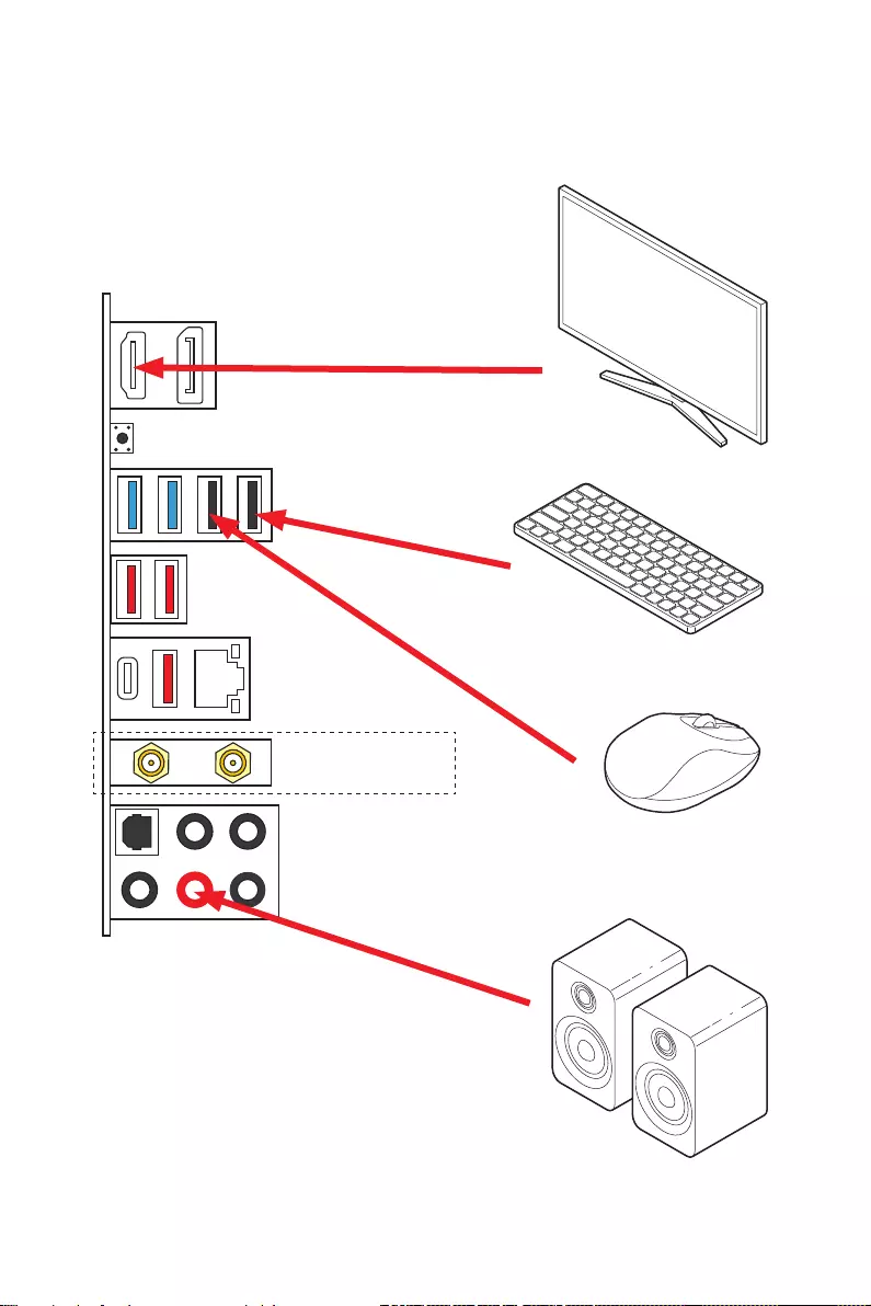
Quick Start
Connecting Peripheral Devices
(MAG Z690 TOMAHAWK WIFI)
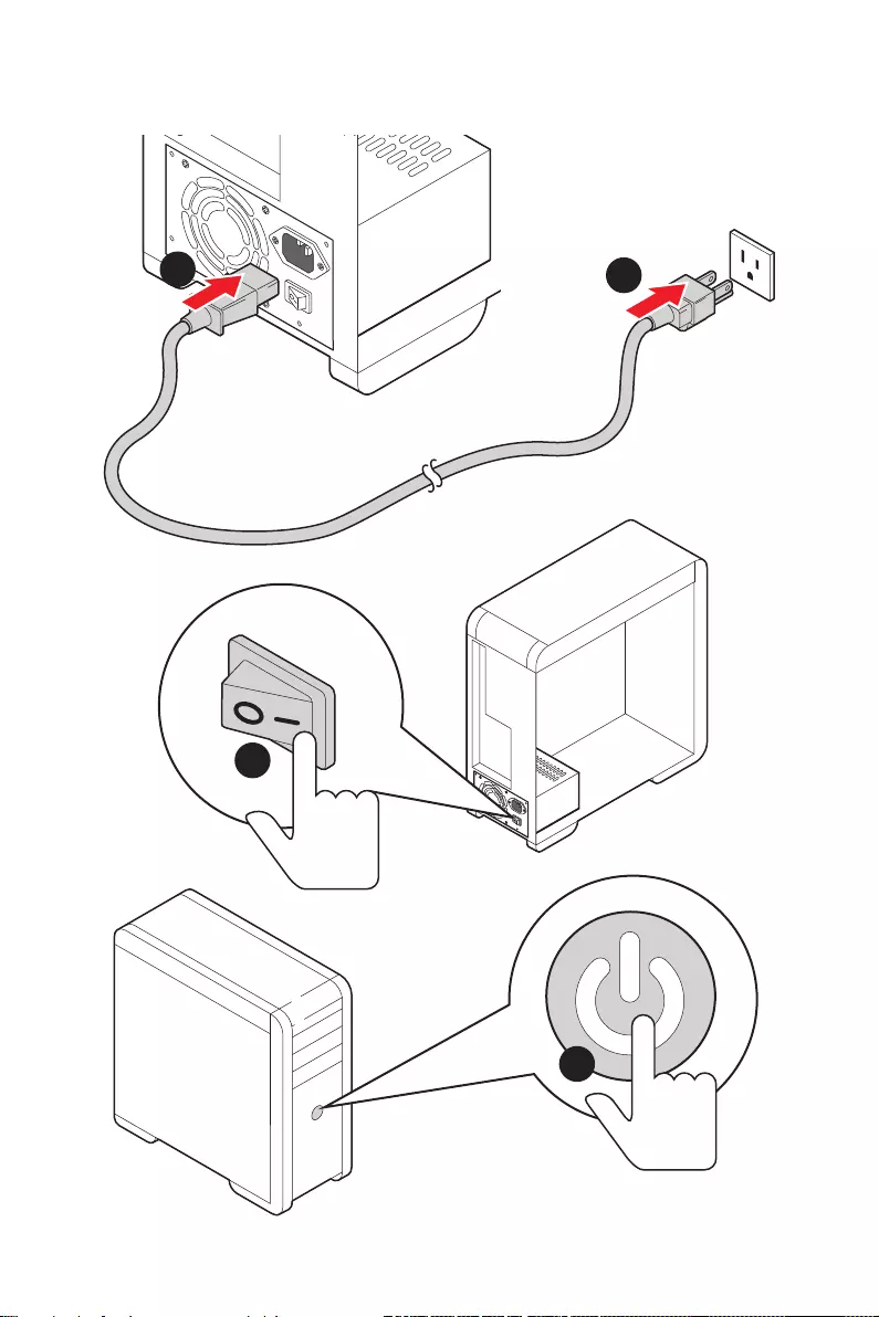
12 Quick Start
Power On
4
3
12

13
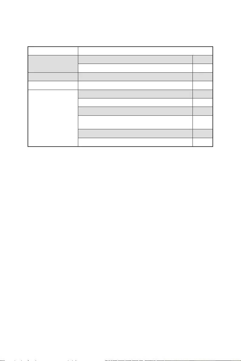
Contents
Contents
Quick Start ………………………………………………………………………………………………. 1
Preparing Tools and Components……………………………………………………………….. 1
Safety Information …………………………………………………………………………………….. 2
Case stand-off notification …………………………………………………………………………. 3
Avoid collision notification ………………………………………………………………………….. 3
Installing a Processor ……………………………………………………………………………….. 4
Installing DDR5 memory ……………………………………………………………………………. 5
Connecting the Front Panel Header ……………………………………………………………. 6
Installing the Motherboard …………………………………………………………………………. 7
Connecting the Power Connectors ……………………………………………………………… 8
Installing SATA Drives ……………………………………………………………………………….. 9
Installing a Graphics Card ………………………………………………………………………… 10
Connecting Peripheral Devices …………………………………………………………………. 11
Power On ……………………………………………………………………………………………….. 12
Specifications …………………………………………………………………………………………. 15
Package contents …………………………………………………………………………………… 22
Block Diagram ………………………………………………………………………………………. 23
Rear I/O Panel ……………………………………………………………………………………….. 24
LAN Port LED Status Table ………………………………………………………………………. 24
Audio Ports Configuration ………………………………………………………………………… 24
Realtek Audio Console …………………………………………………………………………….. 25
Overview of Components ………………………………………………………………………… 28
CPU Socket …………………………………………………………………………………………….. 30
DIMM Slots ……………………………………………………………………………………………… 31
PCI_E1~4: PCIe Expansion Slots ……………………………………………………………….. 32
JFP1, JFP2: Front Panel Connectors …………………………………………………………. 32
M2_1~4: M.2 Slots (Key M) ……………………………………………………………………….. 33
SATA1~6: SATA 6Gb/s Connectors …………………………………………………………….. 37
JAUD1: Front Audio Connector …………………………………………………………………. 37
CPU_PWR1~2, ATX_PWR1: Power Connectors …………………………………………… 38
JDASH1 : Tuning Controller connector ………………………………………………………. 39
JCI1: Chassis Intrusion Connector …………………………………………………………….. 39
JUSB4: USB 3.2 Gen 2 Type-C Connector …………………………………………………… 40
JUSB3: USB 3.2 Gen 1 Connector ……………………………………………………………… 40
JUSB1~2: USB 2.0 Connectors ………………………………………………………………….. 41
JTPM1: TPM Module Connector ………………………………………………………………… 41
CPU_FAN1, PUMP_FAN1, SYS_FAN1~6: Fan Connectors ……………………………. 42

14 Contents
JBAT1: Clear CMOS (Reset BIOS) Jumper ………………………………………………….. 43
JTBT1: Thunderbolt Add-on Card Connector ……………………………………………… 43
JRGB1: RGB LED connector ……………………………………………………………………… 44
JRAINBOW1~3: Addressable RGB LED connectors …………………………………….. 45
Onboard LEDs ………………………………………………………………………………………… 46
EZ Debug LED …………………………………………………………………………………………. 46
LED_SW1: EZ LED Control ……………………………………………………………………….. 46
Installing OS, Drivers & MSI Center ………………………………………………………….. 47
Installing Windows 10/ Windows 11 …………………………………………………………… 47
Installing Drivers …………………………………………………………………………………….. 47
MSI Center ……………………………………………………………………………………………… 47
UEFI BIOS ………………………………………………………………………………………………. 48
BIOS Setup ……………………………………………………………………………………………… 49
Entering BIOS Setup ………………………………………………………………………………… 49
BIOS User Guide ……………………………………………………………………………………… 49
Resetting BIOS ………………………………………………………………………………………… 50
Updating BIOS …………………………………………………………………………………………. 50
RAID Configuration …………………………………………………………………………………. 52
Intel® Optane™ Memory Configuration …………………………………………………….. 53
Troubleshooting ……………………………………………………………………………………. 54

15
Specifications
Specifications
CPU
∙Supports 12th Gen Intel® Core™ Processors, Pentium®
Gold and Celeron® Processors
∙Processor socket LGA1700
* Please go to www.msi.com to get the newest support status as new processors
are released.
Chipset Intel® Z690 Chipset
Memory
∙4x DDR5 memory slots, supporting up to 128GB*
∙Supports 1R 4800 MHz (by JEDEC & POR)
∙Max. overclocking frequency:
▪1DPC 1R Max speed up to 6400+ MHz
▪1DPC 2R Max speed up to 5400+ MHz
▪2DPC 1R Max speed up to 4000+ MHz
▪2DPC 2R Max speed up to 4000+ MHz
∙Supports Intel® XMP 3.0 OC
∙Supports Dual Controller Dual-Channel mode
∙Supports non-ECC, un-buffered memory
* Please refer to www.msi.com for more information on compatible memory.
Expansion Slot
∙3x PCIe x16 slots
▪PCI_E1 (From CPU)
▫Support up to PCIe 5.0 x16
▪PCI_E3 (From Z690 chipset)
▫Support up to PCIe 3.0 x4
▪PCI_E4 (From Z690 chipset)
▫Support up to PCIe 3.0 x1
∙1x PCIe 3.0 x1 slot (From Z690 chipset)
Multi-GPU ∙Supports AMD CrossFire™ Technology
Onboard Graphics
∙1x HDMI 2.1 with HDR port, supporting a maximum
resolution of 4K 60Hz*/**
∙1x DisplayPort 1.4 port with HBR3, supporting a maximum
resolution of 4K 60Hz*/**
* Available only on processors featuring integrated graphics.
** Graphics specifications may vary depending on the CPU installed.
Continued on next column

16 Specifications
Continued from previous column
Storage
∙6x SATA 6Gb/s ports (From Z690 chipset)
∙4x M.2 slots (Key M)
▪M2_1 slot (From CPU)
▫Supports up to PCIe 4.0 x4
▫Supports 2242/ 2260/ 2280/ 22110 storage devices
▪M2_2 slot (From Z690 chipset)
▫Supports up to PCIe 4.0 x4
▫Supports 2242/ 2260/ 2280 storage devices
▪M2_3 slot (From Z690 chipset)
▫Supports up to PCIe 3.0 x4
▫Supports up to SATA 6Gb/s
▫Supports 2242/ 2260/ 2280 storage devices
▪M2_4 slot (From Z690 chipset)
▫Supports up to PCIe 4.0 x4
▫Supports up to SATA 6Gb/s
▫Supports 2242/ 2260/ 2280 storage devices
▪M2_2~4 slots support Intel® Optane™ Memory
∙Supports Intel® Smart Response Technology for Intel
Core™ processors
RAID
∙Supports RAID 0, RAID 1 , RAID 5 and RAID 10 for SATA
storage devices
∙Supports RAID 0, RAID 1 and RAID 5 for M.2 NVMe storage
devices
USB
∙Intel® Z690 Chipset
▪1x USB3.2 Gen2x2 20Gbps Type-C port on the back
panel
▪4x USB 3.2 Gen 2 10Gbps ports (1 Type-C internal
connector, 3 Type-A ports on the back panel)
▪4x USB 3.2 Gen 1 5Gbps ports (2 Type-A ports on the
back panel, 2 ports through the internal connector)
▪1x USB 2.0 Type-A port on the back panel
∙Hub-GL850G
▪5x USB 2.0 ports (1 Type-A port on the back panel, 4
Type-A ports available through internal connectors)
Continued on next column

17
Specifications
Continued from previous column
Audio
Realtek® ALC4080 Codec
∙7.1-Channel High Definition Audio
∙Supports S/PDIF output
LAN ∙1x Intel® I225V 2.5Gbps LAN controller
Wireless LAN
& Bluetooth®
(For MAG Z690
TOMAHAWK WIFI)
∙Intel® Wi-Fi 6E
∙The Wireless module is pre-installed in the M.2 (Key-E)
slot
∙Supports MU-MIMO TX/RX, 2.4GHz/ 5GHz/ 6GHz*(160MHz)
up to 2.4Gbps
∙Supports 802.11 a/ b/ g/ n/ ac/ ax
∙Supports Bluetooth® 5.2**, FIPS, FISMA
* Wi-Fi 6E 6GHz may depend on every country’s regulations and will be ready in
Windows 10 build 21H1 and Windows 11.
** Bluetooth 5.2 will be ready in Windows 10 build 21H1 and Windows 11.
Internal Connectors
∙1x 24-pin ATX main power connector
∙2x 8-pin ATX 12V power connectors
∙6x SATA 6Gb/s connectors
∙4x M.2 slots (M-Key)
∙1x USB 3.2 Gen 2 10Gbps Type-C port
∙1x USB 3.2 Gen 1 5Gbps connector (supports additional 2
USB 3.2 Gen 1 5Gbps ports)
∙2x USB 2.0 Type-A connectors (supports additional 4 USB
2.0 ports)
∙1x 4-pin CPU fan connector
∙1x 4-pin water-pump fan connector
∙6x 4-pin system fan connectors
∙1x Front panel audio connector
∙2x System panel connectors
∙1x Chassis Intrusion connector
∙1x TPM module connector
∙1x Clear CMOS jumper
∙1x TBT connector (supports RTD3)
∙1x Tuning Controller connector
Continued on next column

18 Specifications
Continued from previous column
LED Features
∙1x EZ LED Control switch
∙ 1x 4-pin RGB LED connector
∙ 3x 3-pin RAINBOW LED connectors
∙ 4x EZ Debug LED
Back Panel
Connectors
∙1x DisplayPort port
∙1x HDMI port
∙1x Flash BIOS button
∙2x USB 2.0 Type-A ports
∙2x USB 3.2 Gen1 5Gbps Type-A ports
∙1x LAN I225V port
∙3x USB 3.2 Gen 2 10Gbps Type-A port
∙1x USB 3.2 Gen 2×2 20Gbps Type-C port
∙2x Wi-Fi Antenna connectors (For MAG Z690 TOMAHAWK
WIFI)
∙5x Audio jacks
∙1x Optical S/PDIF Out connector
I/O Controller NUVOTON NCT6687-R Controller Chip
Hardware Monitor
∙CPU/ System/ Chipset temperature detection
∙CPU/ System/ Pump fan speed detection
∙CPU/ System/ Pump fan speed control
Form Factor ∙ATX Form Factor
∙12 in. x 9.6 in. (30.5 cm x 24.4 cm)
BIOS Features
∙1x 256 Mb flash
∙UEFI AMI BIOS
∙ACPI 6.4, SMBIOS 3.4
∙Multi-language
Continued on next column

19
Specifications
Continued from previous column
Software
∙Drivers
∙MSI Center
∙Intel Extreme Tuning Utility
∙MSI APP Player (BlueStacks)
∙Open Broadcaster Software (OBS)
∙CPU-Z MSI GAMING
∙Google Chrome™, Google Toolbar, Google Drive
∙Norton™ Internet Security Solution
MSI Center
Features
∙Gaming Mode
∙Smart Priority
∙Game Highlights
∙LAN Manager
∙Mystic Light
∙Ambient Devices
∙Frozr AI Cooling
∙User Scenario
∙True Color
∙Live Update
∙Hardware Monitoring
∙Super Charger
∙Speed Up
∙Smart Image Finder
∙MSI Companion
Continued on next column

20 Specifications
Continued from previous column
Special Features
∙Audio
▪Audio Boost 5
∙Network
▪2.5G LAN
▪LAN Manager
▪Intel Wi-Fi (For MAG Z690 TOMAHAWK WIFI)
∙Cooling
▪All Aluminum Design
▪Extended Heatsink Design
▪M.2 Shield Frozr
▪Pump Fan
▪Smart Fan Control
▪7W/mK MOSFET thermal pad
▪Choke thermal pad
∙LED
▪Mystic Light Extension (RAINBOW/RGB)
▪Mystic Light SYNC
▪Ambient Devices Support
Continued on next column

21
Specifications
Continued from previous column
Special Features
∙Performance
▪Multi GPU-CrossFire Technology
▪Memory Boost
▪Core Boost
▪GAME Boost
▪Lightning USB 20G
▪USB 3.2 Gen 2 10G
▪USB with Type A+C
▪Front USB Type-C
▪Dual CPU Power: 8+8 pin
▪Lightning Gen 5 PCI-E Slot
▪Lightning Gen 4 M.2
▪Server PCB
▪2oz Copper thickened PCB
∙Protection
▪PCI-E Steel Armor
▪Pre-installed I/O Shielding
∙Experience
▪MSI Center
▪Click BIOS 5
▪EZ M.2 Clip
▪Flash BIOS Button
▪Frozr AI Cooling
▪EZ LED Control
▪EZ DEBUG LED
▪App player
▪Tile
22 Package contents
Package contents
Please check the contents of your motherboard package. It should contain:
Motherboard MAG Z690 TOMAHAWK WIFI/ MAG Z690 TORPEDO
Documentation User manual 1
Quick installation guide 1
Application USB drive with drivers & utilities 1
Cables SATA 6Gb/s cables (2 cables/pack) 1
Accessories
Wi-Fi antenna (For MAG Z690 TOMAHAWK WIFI) 1
Case badge 1
EZ M.2 clip (1 set/pack) 1
M.2 screw + standoff (1 set/pack) (For MAG Z690
TORPEDO) 1
MAG sticker 1
Product registration card 1
⚠
Important
If any of the above items are damaged or missing, please contact your retailer.
23
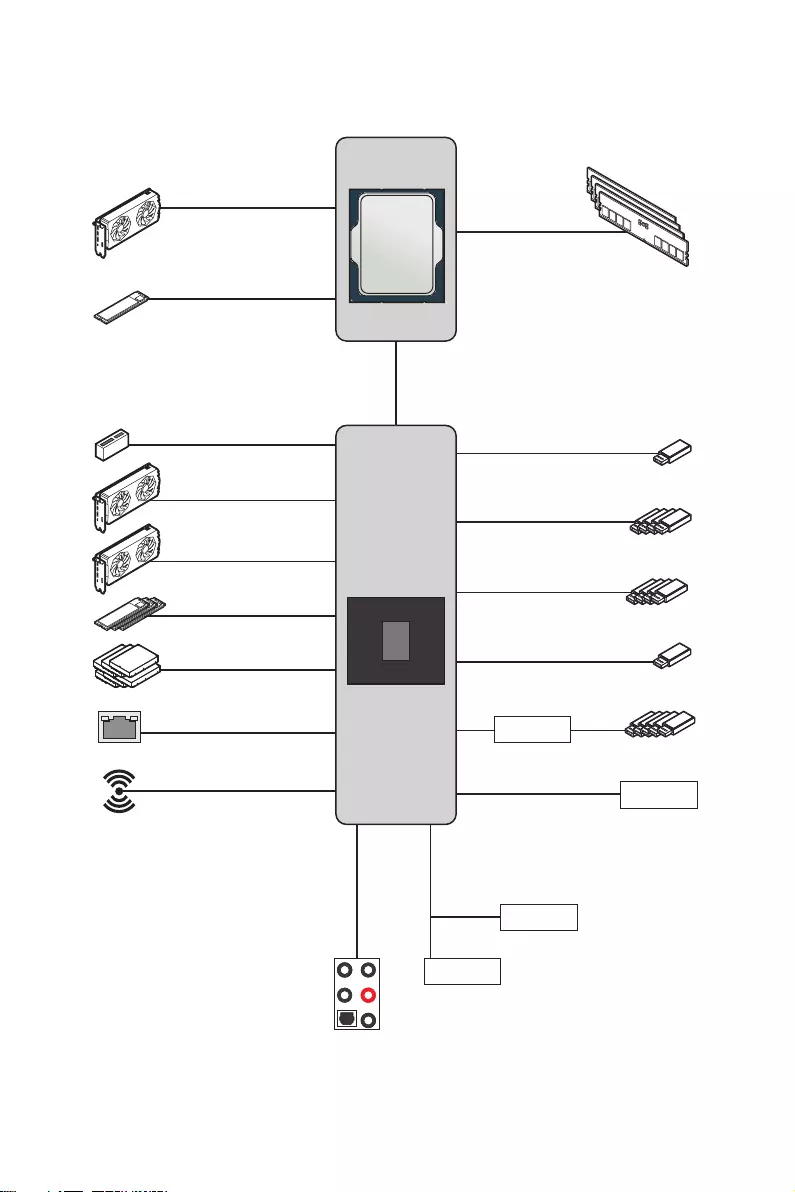
Block Diagram
Block Diagram
CPU
PCH
PCI_E1
PCIe x16
DDR5 2Channel
DIMM A1/A2
DIMM B1/B2
DMI x8
Intel WiFi (For MAG Z690
TOMAHAWK WIFI)
Intel LAN I225
HD Audio
ALC4080
M2_1
SATA1/2/3/4/5/6
M2_2, M2_3, M2_4
PCI_E4
PCIe 3.0 x1
PCI_E3
PCIe 3.0 x4
SIO 6687
TPM
SPI
MCU
USB 3.2 Gen 2 10Gbps
USB 3.2 Gen 1 5Gbps
USB 2.0
USB 2.0
Hub-GL850G
USB3.2 Gen2x2 20Gbps
PCI_E2
PCIe 3.0 x1
⚠
Important
The icons above are for reference only.
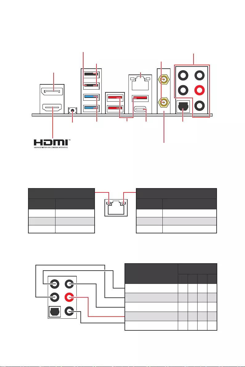
24 Rear I/O Panel
Audio Ports Configuration
Audio Ports Channel
2468
Center/ Sub-woofer Out
Rear Speaker Out
Line-In/ Side Speaker Out
Line-Out/ Front Speaker Out
Mic In
Blank: empty)
LAN Port LED Status Table
Link/ Activity LED
Status Description
Off No link
Yellow Linked
Blinking Data activity
Speed LED
Status Description
Off 10 Mbps connection
Green 100/1000 Mbps connection
Orange 2.5 Gbps connection
Rear I/O Panel
∙Flash BIOS Port/ Button — Please refer to page 51 for Updating BIOS with Flash
BIOS Button.
USB 3.2
Gen 2×2
(20Gbps)
Type-C
Flash BIOS
Button
2.5Gbps
LAN
Wi-Fi Antenna
connectors
USB 2.0
Type-A
USB 3.2
Gen 2
(10Gbps)
Type-A
USB 3.2
Gen 1
(5Gbps)
Type-A
DisplayPort
Audio Ports
Optical
S/PDIF-Out
For MAG Z690
TOMAHAWK WIFI
Flash BIOS
port
25
Rear I/O Panel
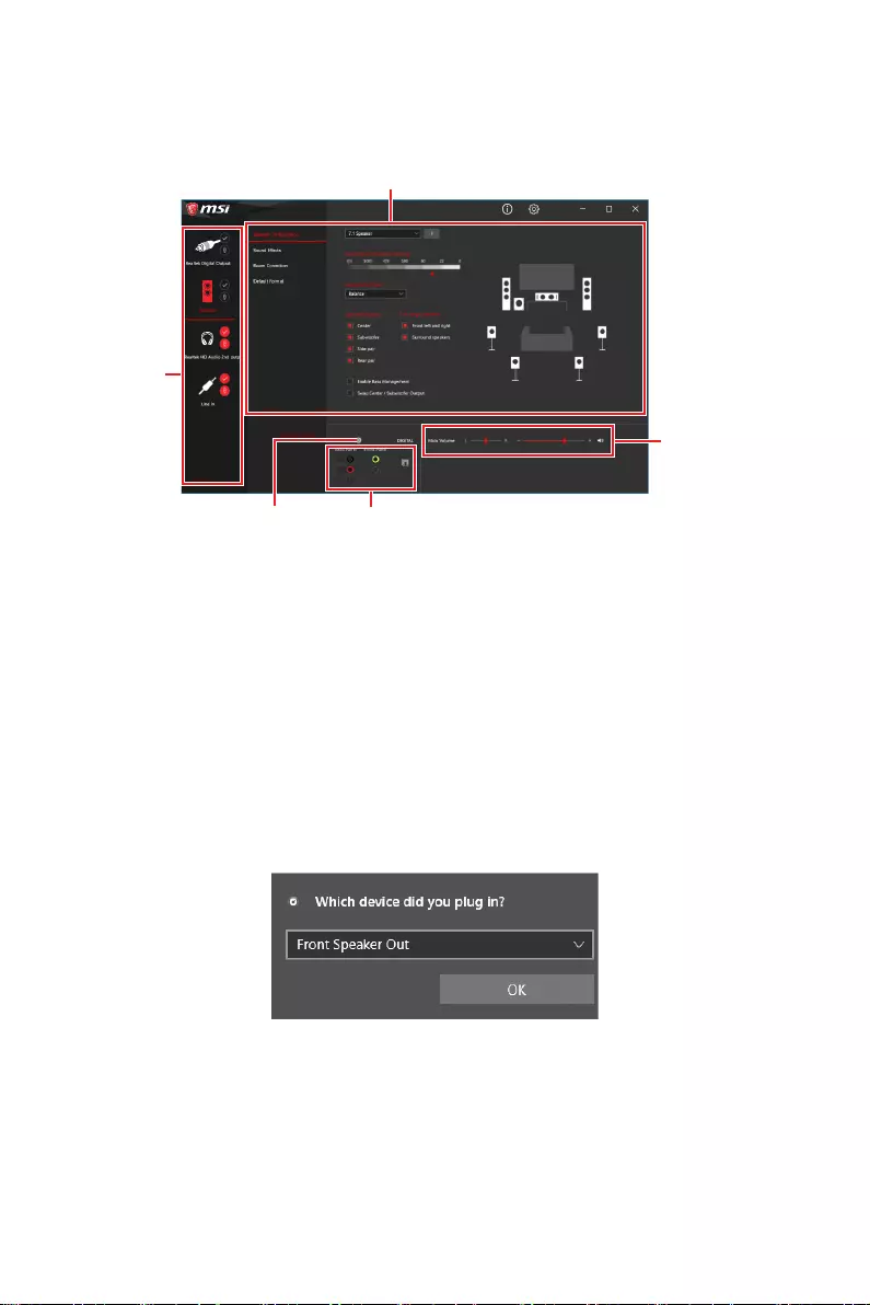
Realtek Audio Console
After Realtek Audio Console is installed. You can use it to change sound settings to get
better sound experience.
Jack Status
Connector Settings
Device
Selection
Main Volume
Application Enhancement
∙Device Selection — allows you to select a audio output source to change the related
options. The check sign indicates the devices as default.
∙Application Enhancement — the array of options will provide you a complete
guidance of anticipated sound effect for both output and input device.
∙Main Volume — controls the volume or balance the right/left side of the speakers
that you plugged in front or rear panel by adjust the bar.
∙Jack Status — depicts all render and capture devices currently connected with your
computer.
∙Connector Settings — configures the connection settings.
Auto popup dialog
When you plug into a device at an audio jack, a dialogue window will pop up asking you
which device is current connected.
Each jack corresponds to its default setting as shown on the next page.
⚠
Important
The pictures above for reference only and may vary from the product you purchased.
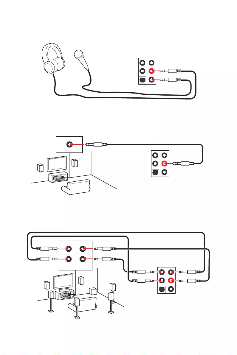
26 Rear I/O Panel
Audio jacks to headphone and microphone diagram
Audio jacks to stereo speakers diagram
Audio jacks to 7.1-channel speakers diagram
AUDIO INPUT
AUDIO INPUT
Rear Front
Side Center/
Subwoofer
27
Rear I/O Panel
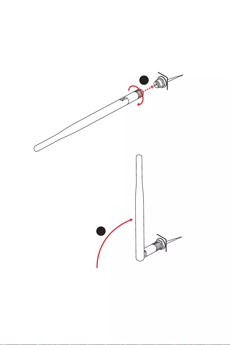
Installing antennas
1. Screw the antennas tight to the antenna connectors as shown below.
2. Orient the antennas.
1
2
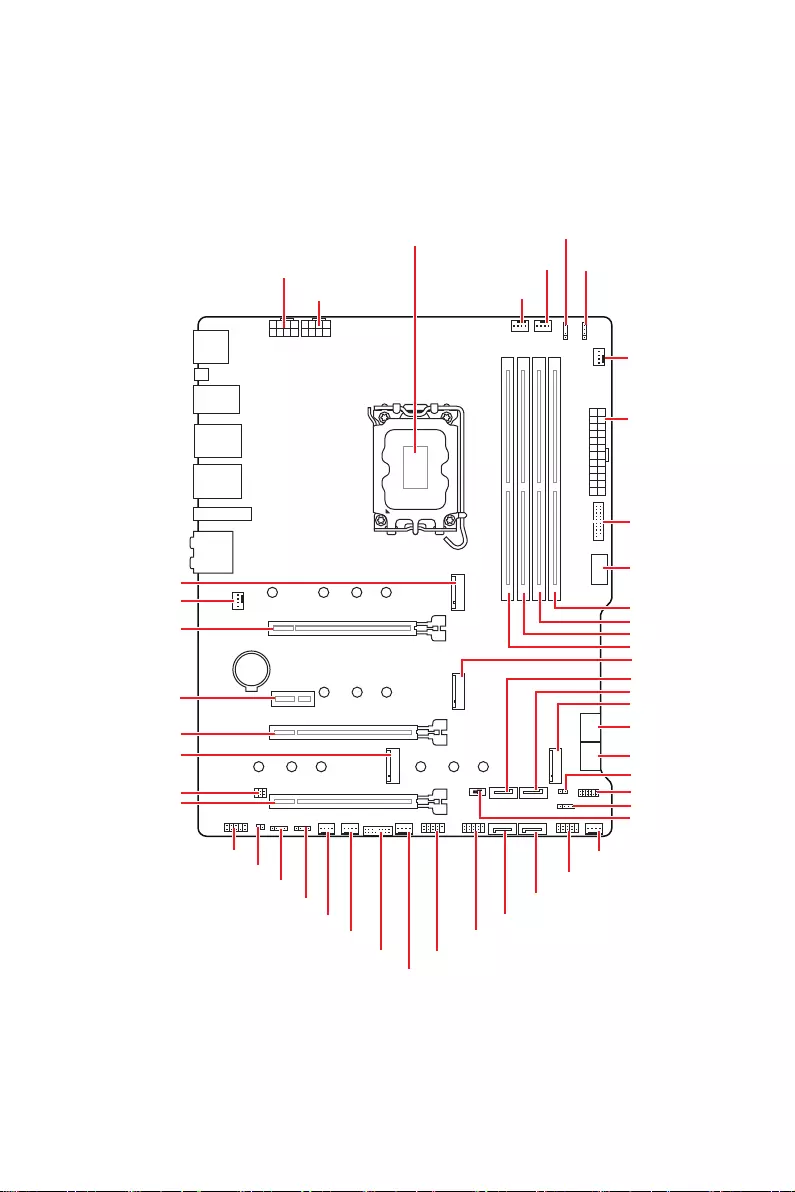
28 Overview of Components
Overview of Components
BAT1
JTBT1
SATA3
SATA5
SATA6
SATA1
SATA2
SATA4
M2_2
M2_4
M2_3
M2_1
JTPM1
SYS_FAN4
SYS_FAN3
SYS_FAN5
SYS_FAN6
SYS_FAN1
JUSB2
JUSB1
CPU_FAN1
PUMP_FAN1
PCI_E1
PCI_E2
PCI_E4
JDASH1
Processor Socket
CPU_PWR1
JAUD1
JFP1
JRAINBOW2
JRAINBOW1
JFP2
ATX_PWR1
DIMMB1
DIMMB2
DIMMA1
DIMMA2
CPU_PWR2
JRAINBOW3
JRGB1
SYS_FAN2
JUSB3
JUSB4
JCI1
LED_SW1
PCI_E3
JBAT1
29
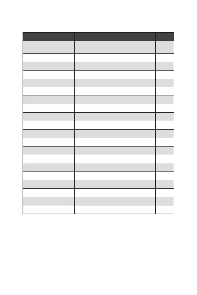
Overview of Components
Component Contents
Port Name Port Type Page
CPU_FAN1, PUMP_FAN1,
SYS_FAN1~6 Fan Connectors 42
CPU_PWR1~2, ATX_PWR1 Power Connectors 38
CPU Socket LGA1700 CPU Socket 30
DIMM Slots Memory slots 31
JAUD1 Front Audio Connector 37
JBAT1 Clear CMOS (Reset BIOS) Jumper 43
JCI1 Chassis Intrusion Connector 39
JDASH1 Tuning Controller connector 39
JFP1, JFP2 Front Panel Connectors 32
JRAINBOW1~3 Addressable RGB LED connectors 45
JRGB1 RGB LED connector 44
JTBT1 Thunderbolt Add-on Card Connector 43
JTPM1 TPM Module Connector 41
JUSB1~2 USB 2.0 Connectors 41
JUSB3 USB 3.2 Gen 1 Connector 40
JUSB4 USB 3.2 Gen 2 Type-C Connector 40
LED_SW1 EZ LED Control 46
M2_1~4 M.2 Slots (Key M) 33
PCI_E1~4 PCIe Expansion Slots 32
SATA1~6 SATA 6Gb/s Connectors 37
30 Overview of Components
⚠
Important
∙
Always unplug the power cord from the power outlet before installing or removing
the CPU.
∙
Please retain the CPU protective cap after installing the processor. MSI will deal
with Return Merchandise Authorization (RMA) requests if only the motherboard comes
with the protective cap on the CPU socket.
∙
When installing a CPU, always remember to install a CPU heatsink. A CPU heatsink
is necessary to prevent overheating and maintain system stability.
∙
Confirm that the CPU heatsink has formed a tight seal with the CPU before booting
your system.
∙
Overheating can seriously damage the CPU and motherboard. Always make sure
the cooling fans work properly to protect the CPU from overheating. Be sure to apply
an even layer of thermal paste (or thermal tape) between the CPU and the heatsink to
enhance heat dissipation.
∙
Whenever the CPU is not installed, always protect the CPU socket pins by covering
the socket with the plastic cap.
∙
If you purchased a separate CPU and heatsink/ cooler, Please refer to the
documentation in the heatsink/ cooler package for more details about installation.
∙
This motherboard is designed to support overclocking. Before attempting to
overclock, please make sure that all other system components can tolerate
overclocking. Any attempt to operate beyond product specifications is not
recommended. MSI® does not guarantee the damages or risks caused by inadequate
operation beyond product specifications.
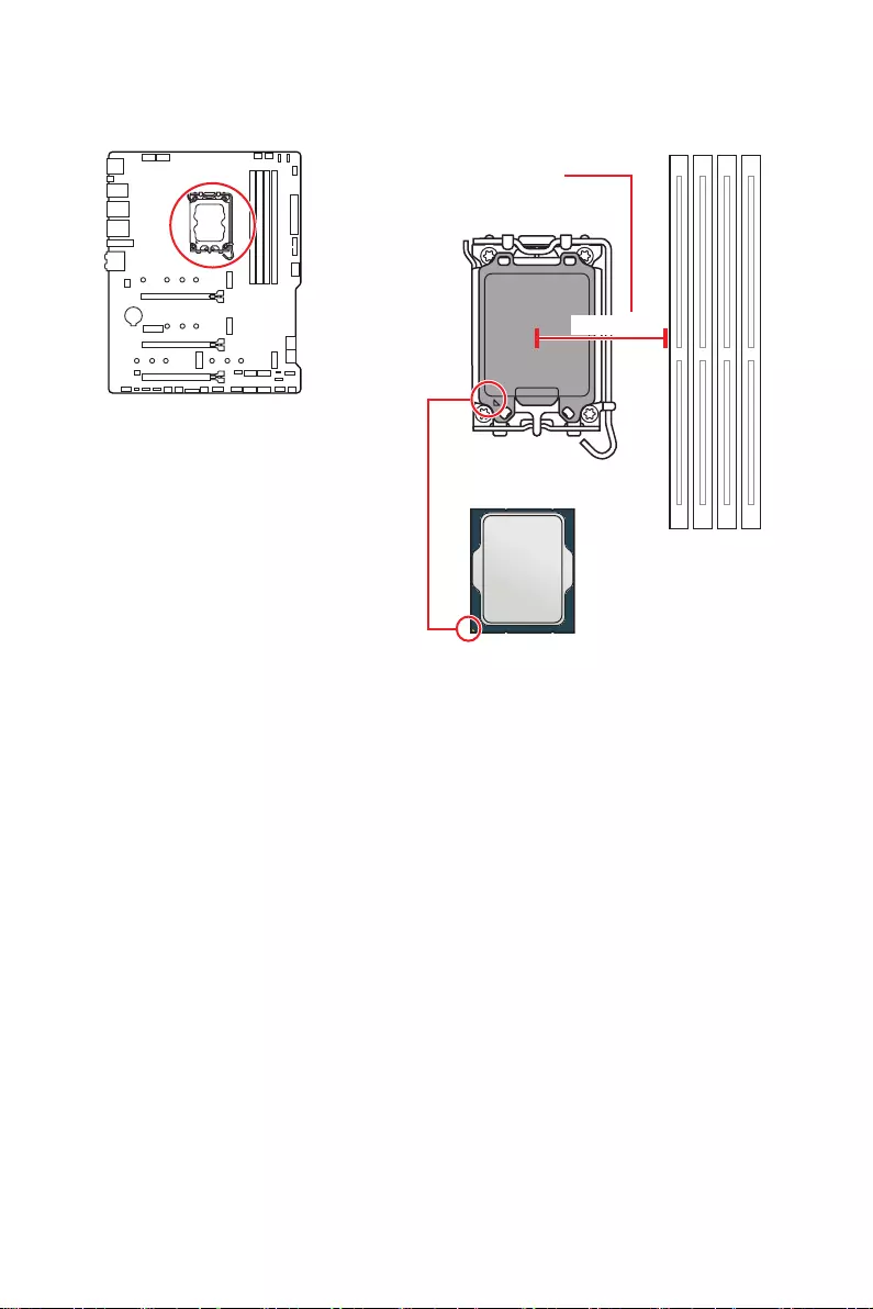
CPU Socket
Introduction to the LGA1700 CPU
The surface of the LGA1700 CPU has
four notches and a golden triangle to
assist in correctly lining up the CPU for
motherboard placement. The golden
triangle is the Pin 1 indicator.
Distance from the center of the
CPU to the nearest DIMM slot.
52.4 mm
31
Overview of Components
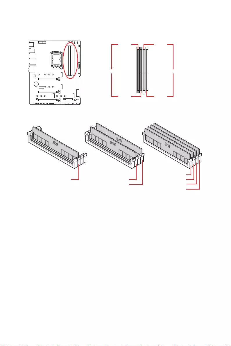
DIMM Slots
DIMMA1 DIMMB1
Channel A Channel B
DIMMA2 DIMMB2
Memory module installation recommendation
⚠
Important
∙
Always insert memory modules in the DIMMA2 slot first.
∙
To ensure system stability for Dual channel mode, memory modules must be of the
same type, number and density.
∙
Some memory modules may operate at a lower frequency than the marked value
when overclocking due to the memory frequency operates dependent on its Serial
Presence Detect (SPD). Go to BIOS and find the DRAM Frequency to set the memory
frequency if you want to operate the memory at the marked or at a higher frequency.
∙
It is recommended to use a more efficient memory cooling system for full DIMMs
installation or overclocking.
∙
The stability and compatibility of installed memory module depend on installed CPU
and devices when overclocking.
∙
Please refer to www.msi.com for more information on compatible memory.
DIMMA2 DIMMA2
DIMMB2
DIMMA1
DIMMA2
DIMMB1
DIMMB2
32 Overview of Components
PCI_E1~4: PCIe Expansion Slots
PCI_E1: PCIe 5.0 x16 (From CPU)
PCI_E2: PCIe 3.0 x1 (From Z690 chipset)
PCI_E3: PCIe 3.0 x4 (From Z690 chipset)
PCI_E4: PCIe 3.0 x1 (From Z690 chipset)
⚠
Important
∙
If you install a large and heavy graphics card, you need to use a tool such as MSI
Graphics Card Bolster to support its weight to prevent deformation of the slot.
∙
For a single PCIe x16 expansion card installation with optimum performance, using
the PCI_E1 slot is recommended.
∙
When adding or removing expansion cards, always turn off the power supply and
unplug the power supply power cable from the power outlet. Read the expansion
card’s documentation to check for any necessary additional hardware or software
changes.
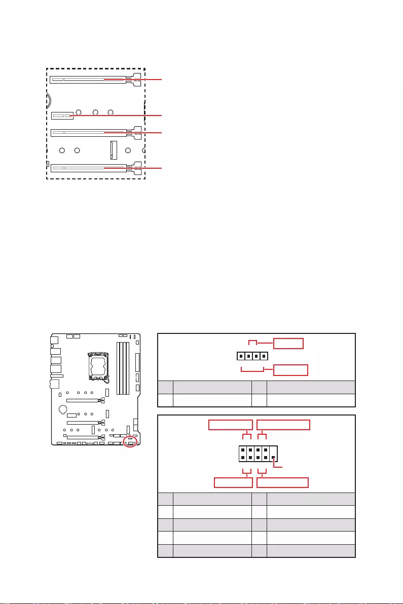
JFP1, JFP2: Front Panel Connectors
These connectors connect to the switches and LEDs on the front panel.
1
2 10
9
+
+
+— ——
—
+
Power LED
HDD LED Reset Switch
Reserved
Power Switch
JFP1
1 HDD LED + 2 Power LED +
3 HDD LED — 4 Power LED —
5 Reset Switch 6 Power Switch
7 Reset Switch 8 Power Switch
9 Reserved 10 No Pin
1
JFP2
+
+—
—
Speaker
Buzzer
1 Speaker — 2 Buzzer +
3 Buzzer — 4 Speaker +
33
Overview of Components
M2_1~4: M.2 Slots (Key M)
M2_1
M2_2
M2_4
M2_3
⚠
Important
∙
Intel® RST only supports PCIe M.2 SSD with
UEFI ROM.
∙
M2_2~4 slots support Intel® Optane™
Memory.
For MAG Z690 TOMAHAWK WIFI
M.2 slot installation
1. Loosen the screws of M.2 SHIELD FROZR heatsink.
2. Remove the M.2 SHIELD FROZR and remove the protective films from the thermal
pads.
2
2
1
1
1
1
11
M2_2
M2_1
2
M2_3&M2_4
34 Overview of Components
3. If there is no EZ M.2 Clip installed, please install the supplied EZ M.2 Clip kit in the
M.2 slot according to your SSD length.
4. Insert your M.2 SSD into the M.2 slot at a 30-degree angle.
5. Rotate the EZ M.2 Clip to fix the M.2 SSD.
30º30º
3
4
5
6. Put the M.2 SHIELD FROZR heatsink back in place and secure it.
6
6
6
6
6
6
35
Overview of Components
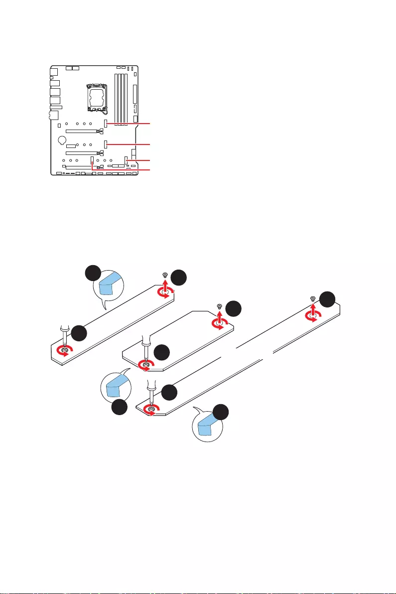
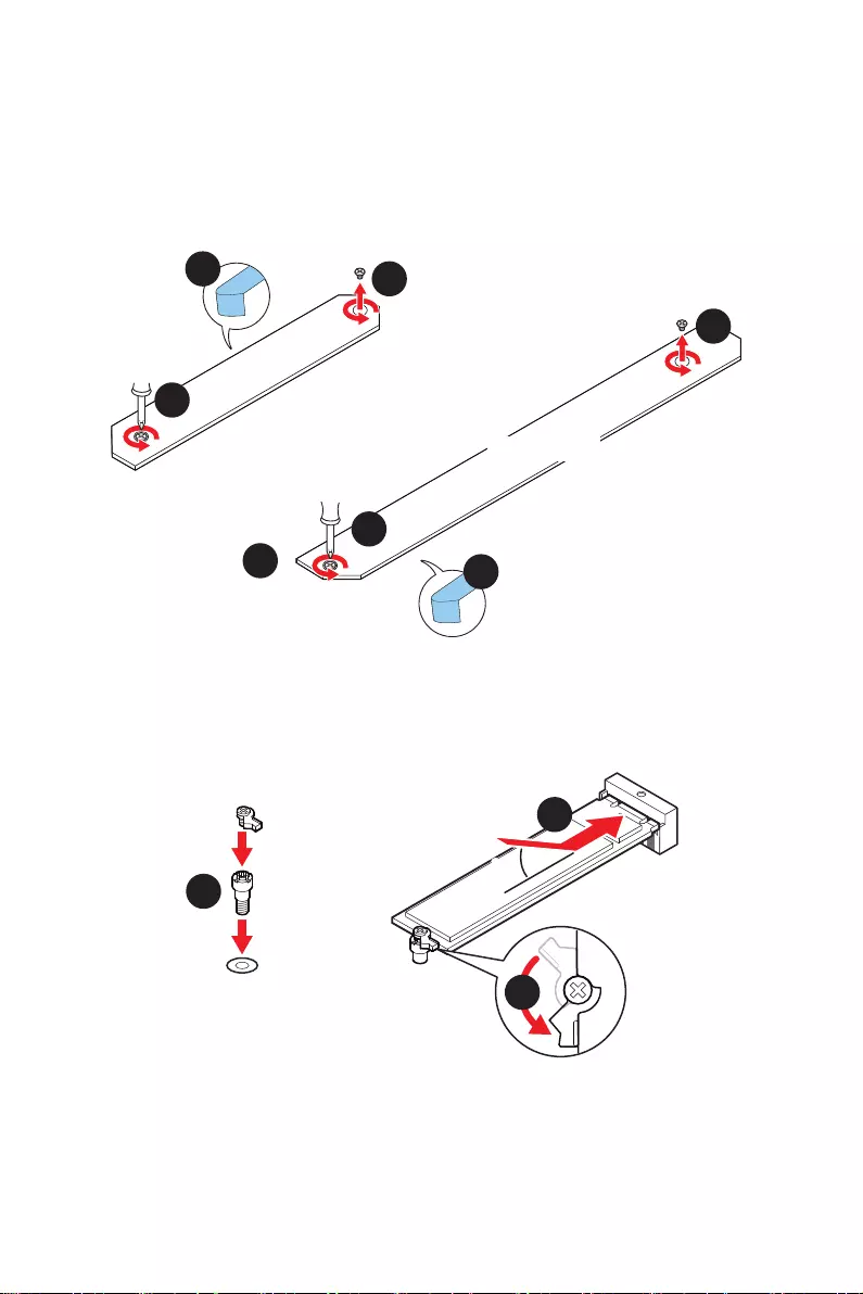
For MAG Z690 TORPEDO
M2_1, M2_3 & M2_4 slot installation
1. Loosen the screws of M.2 SHIELD FROZR heatsink.
2. Remove the M.2 SHIELD FROZR and remove the protective films from the thermal
pads.
2
2
1
1
1
1
M2_1
2
M2_3&M2_4
1. If there is no EZ M.2 Clip installed, please install the supplied EZ M.2 Clip kit in the
M.2 slot according to your SSD length.
2. Insert your M.2 SSD into the M.2 slot at a 30-degree angle.
3. Rotate the EZ M.2 Clip to fix the M.2 SSD.
30º30º
3
4
5
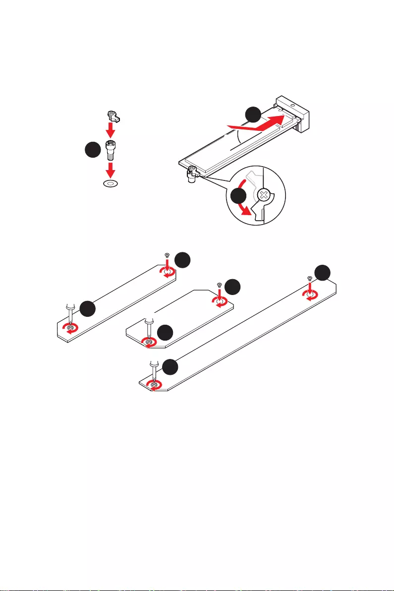
36 Overview of Components
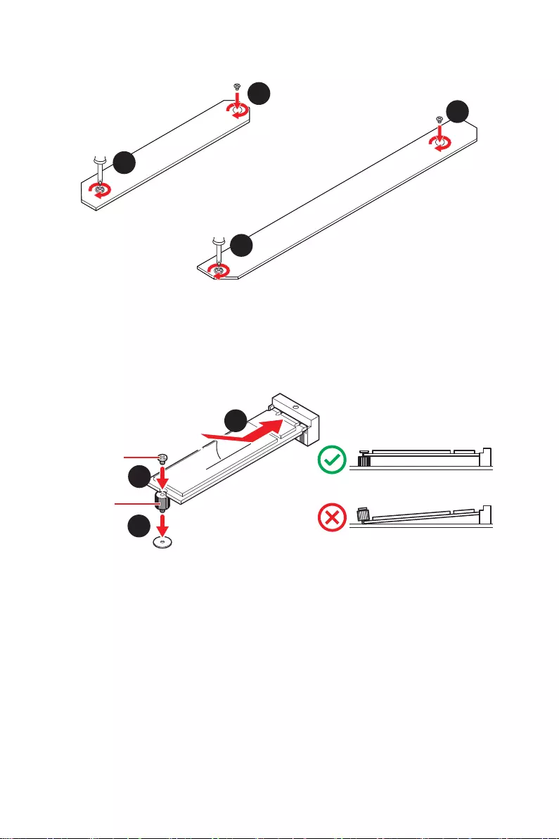
4. Put the M.2 SHIELD FROZR heatsink back in place and secure it.
6
6
6
6
M2_2 slot installation
1. Secure the supplied M.2 standoff according to your M.2 SSD length if need.
2. Insert your M.2 SSD into the M.2 slot at a 30-degree angle.
3. Secure the M.2 SSD in place with the supplied M.2 8.5H screw.
30º30º
5
4
3
8.5H screw
Standoff
37
Overview of Components
JAUD1: Front Audio Connector
This connector allows you to connect audio jacks on the front panel.
1
2 10
9
1 MIC L 2 Ground
3 MIC R 4 NC
5 Head Phone R 6 MIC Detection
7 SENSE_SEND 8 No Pin
9 Head Phone L 10 Head Phone Detection
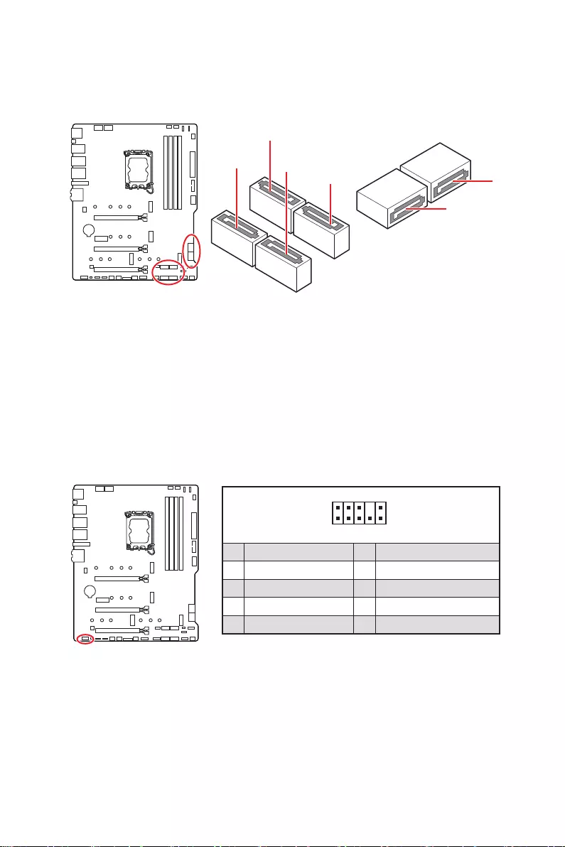
SATA1~6: SATA 6Gb/s Connectors
These connectors are SATA 6Gb/s interface ports. Each connector can connect to one
SATA device.
SATA1
⚠
Important
∙
Please do not fold the SATA cable at a 90-degree angle. Data loss may result during
transmission otherwise.
∙
SATA cables have identical plugs on either sides of the cable. However, it is
recommended that the flat connector be connected to the motherboard for space
saving purposes.
SATA2
SATA6
SATA5
SATA4 SATA3
38 Overview of Components
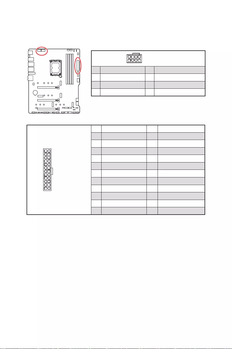
24
131
12
ATX_PWR1
1 +3.3V 13 +3.3V
2 +3.3V 14 -12V
3 Ground 15 Ground
4 +5V 16 PS-ON#
5 Ground 17 Ground
6 +5V 18 Ground
7 Ground 19 Ground
8 PWR OK 20 Res
9 5VSB 21 +5V
10 +12V 22 +5V
11 +12V 23 +5V
12 +3.3V 24 Ground
5
4 1
8CPU_PWR1~2
1 Ground 5 +12V
2 Ground 6 +12V
3 Ground 7 +12V
4 Ground 8 +12V
⚠
Important
Make sure that all the power cables are securely connected to a proper ATX power
supply to ensure stable operation of the motherboard.
CPU_PWR1~2, ATX_PWR1: Power Connectors
These connectors allow you to connect an ATX power supply.
39
Overview of Components
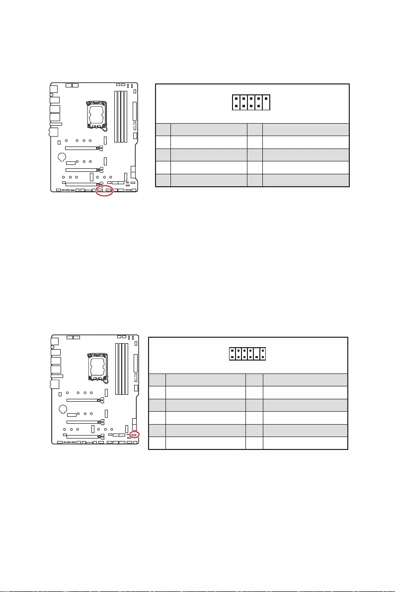
JDASH1 : Tuning Controller connector
This connector is used to connect an optional Tuning Controller module.
1
2 6
5
1 No Pin 2 NC
3 MCU_SMB_SCL_M 4 MCU_SMB_SDA_M
5 VCC5 6 Ground
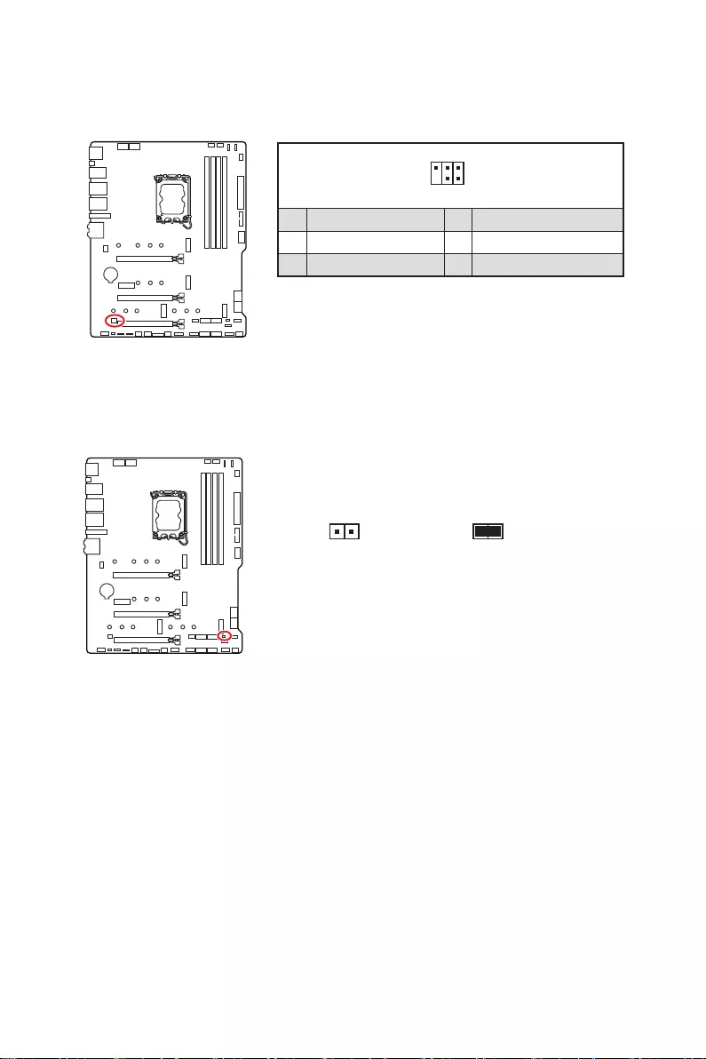
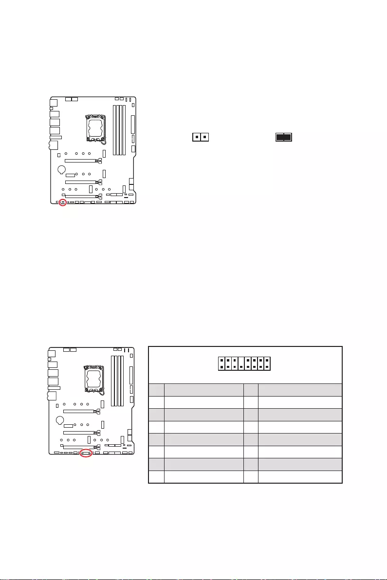
JCI1: Chassis Intrusion Connector
This connector allows you to connect the chassis intrusion switch cable.
Normal
(default) Trigger the chassis
intrusion event
Using chassis intrusion detector
1. Connect the JCI1 connector to the chassis intrusion switch/ sensor on the chassis.
2. Close the chassis cover.
3. Go to BIOS > SETTINGS > Security > Chassis Intrusion Configuration.
4. Set Chassis Intrusion to Enabled.
5. Press F10 to save and exit and then press the Enter key to select Yes.
6. Once the chassis cover is opened again, a warning message will be displayed on
screen when the computer is turned on.
Resetting the chassis intrusion warning
1. Go to BIOS > SETTINGS > Security > Chassis Intrusion Configuration.
2. Set Chassis Intrusion to Reset.
3. Press F10 to save and exit and then press the Enter key to select Yes.
40 Overview of Components
JUSB3: USB 3.2 Gen 1 Connector
This connector allows you to connect USB 3.2 Gen 1 5Gbps ports on the front panel.
⚠
Important
Note that the Power and Ground pins must be connected correctly to avoid possible
damage.
1
10 11
20
1 Power 11 USB2.0+
2 USB3_RX_DN 12 USB2.0-
3 USB3_RX_DP 13 Ground
4 Ground 14 USB3_TX_C_DP
5 USB3_TX_C_DN 15 USB3_TX_C_DN
6 USB3_TX_C_DP 16 Ground
7 Ground 17 USB3_RX_DP
8 USB2.0- 18 USB3_RX_DN
9 USB2.0+ 19 Power
10 Ground 20 No Pin
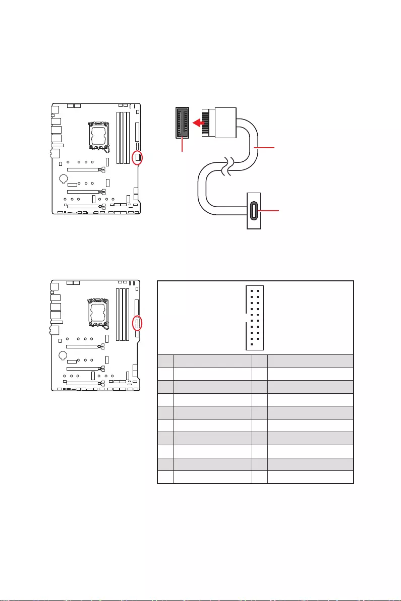
JUSB4: USB 3.2 Gen 2 Type—C Connector
This connector allows you to connect USB 3.2 Gen 2 Type-C connector on the front
panel. The connector possesses a foolproof design. When you connect the cable, be
sure to connect it with the corresponding orientation.
JUSB4 USB Type-C Cable
USB Type-C port on
the front panel
41
Overview of Components
JUSB1~2: USB 2.0 Connectors
These connectors allow you to connect USB 2.0 ports on the front panel.
1
2 10
9
1 VCC 2 VCC
3 USB0- 4 USB1-
5 USB0+ 6 USB1+
7 Ground 8 Ground
9 No Pin 10 NC
⚠
Important
∙
Note that the VCC and Ground pins must be connected correctly to avoid possible
damage.
∙
In order to recharge your iPad, iPhone and iPod through USB ports, please install
MSI Center utility.
JTPM1: TPM Module Connector
This connector is for TPM (Trusted Platform Module). Please refer to the TPM security
platform manual for more details and usages.
1
2 12
11
1 SPI Power 2 SPI Chip Select
3
Master In Slave Out (SPI Data)
4
Master Out Slave In (SPI Data)
5 Reserved 6 SPI Clock
7 Ground 8 SPI Reset
9 Reserved 10 No Pin
11 Reserved 12 Interrupt Request
42 Overview of Components
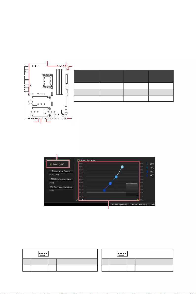
CPU_FAN1, PUMP_FAN1, SYS_FAN1~6: Fan Connectors
Fan connectors can be classified as PWM (Pulse Width Modulation) Mode or DC Mode.
PWM Mode fan connectors provide constant 12V output and adjust fan speed with
speed control signal. DC Mode fan connectors control fan speed by changing voltage.
However, you can follow the instruction below to adjust the fan connector to PWM or
DC Mode manually.
Switching fan mode and adjusting fan speed
You can switch between PWM mode and DC mode and adjust fan speed in BIOS >
HARDWARE MONITOR.
Select PWM mode or DC mode
⚠
Important
Make sure fans are working properly after switching the PWM/ DC mode.
There are gradient points of the fan speed that allow you to adjust
fan speed in relation to CPU temperature.
Pin definition of fan connectors
CPU_FAN1
SYS_FAN6
SYS_FAN3
SYS_FAN4
SYS_FAN5
PUMP_FAN1
SYS_FAN2
SYS_FAN1
Connector Default fan
mode Max.
current Max.
power
CPU_FAN1 PWM mode 2A 24W
PUMP_FAN1 PWM mode 3A 36W
SYS_FAN1~6 DC mode 1A 12W
1 PWM Mode pin definition
1 Ground 2 +12V
3 Sense 4 Speed Control Signal
1 DC Mode pin definition
1 Ground 2 Voltage Control
3 Sense 4 NC
43
Overview of Components
JBAT1: Clear CMOS (Reset BIOS) Jumper
There is CMOS memory onboard that is external powered from a battery located on
the motherboard to save system configuration data. If you want to clear the system
configuration, set the jumpers to clear the CMOS memory.
Keep Data
(default) Clear CMOS/
Reset BIOS
Resetting BIOS to default values
1. Power off the computer and unplug the power cord.
2. Use a jumper cap to short JBAT1 for about 5-10 seconds.
3. Remove the jumper cap from JBAT1.
4. Plug the power cord and Power on the computer.
JTBT1: Thunderbolt Add-on Card Connector
This connector allows you to connect the add-on Thunderbolt I/O card.
1
2 16
15
1 TBT_FORCE_PWR 2 TBT_S0IX_ENTRY_REQ
3 TBT_CIO_PLUG_EVENT# 4 TBT_S0IX_ENTRY_ACK
5 SLP_S3#_TBT 6 TBT_PSON_OVERRIDE_N
7 SLP_S5#_TBT 8 No Pin
9 Ground 10 SMBCLK_VSB
11 DG_PEWAKE# 12 SMBDATA_VSB
13 TBT_RTD3_PWR_EN 14 Ground
15 TBT_CARD_DET_R# 16 PD_IRQ#
44 Overview of Components
⚠
Important
∙
The JRGB connector supports up to 2 meters continuous 5050 RGB LED strips
(12V/G/R/B) with the maximum power rating of 3A (12V).
∙
Always turn off the power supply and unplug the power cord from the power outlet
before installing or removing the RGB LED strip.
∙
Please use MSI’s software to control the extended LED strip.
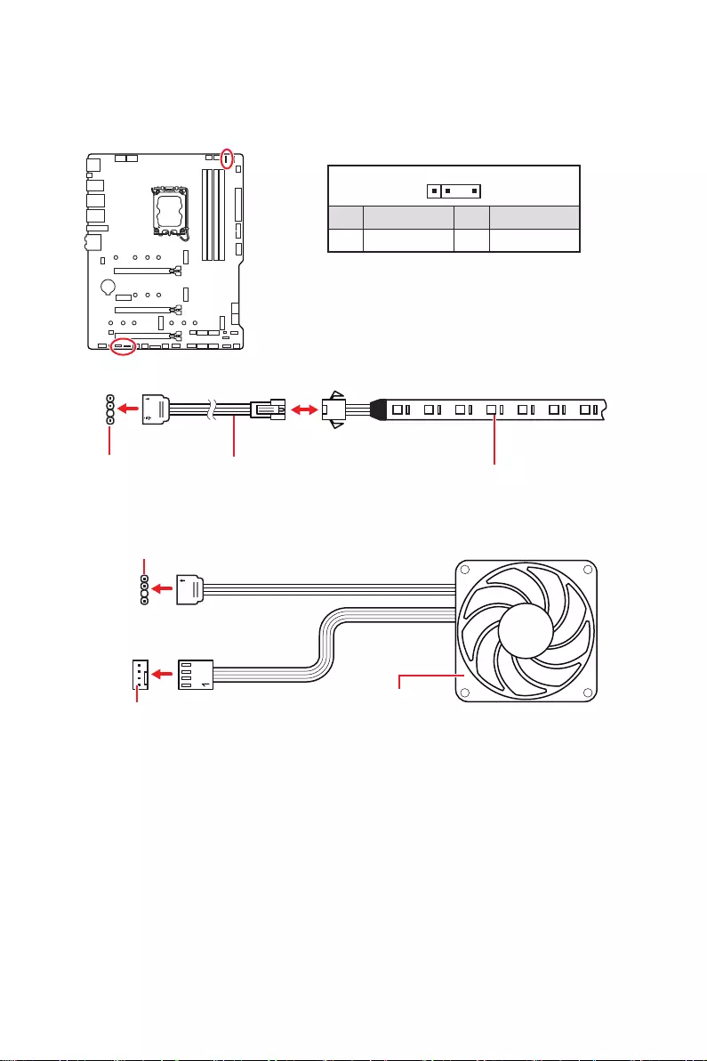
JRGB1: RGB LED connector
The JRGB connector allows you to connect the 5050 RGB LED strips 12V.
1
GRB
JRGB
connector
JRGB extension
cable 5050 RGB LED strips 12V
1
1 +12V 2 G
3 R 4 B
RGB LED Strip Connection
1
1
GRB
JRGB connector
System Fan connector
RGB LED Fan Connection
RGB LED Fan
45
Overview of Components
1
1
1
D
+5V
⚠
CAUTION
Do not connect the wrong type of LED strips. The JRGB connector and the JRAINBOW
connector provide different voltages, and connecting the 5V LED strip to the JRGB
connector will result in damage to the LED strip.
⚠
Important
∙
The JRAINBOW connector supports up to 75 LEDs WS2812B Individually
Addressable RGB LED strips (5V/Data/Ground) with the maximum power rating of 3A
(5V). In the case of 20% brightness, the connector supports up to 200 LEDs.
∙
Always turn off the power supply and unplug the power cord from the power outlet
before installing or removing the RGB LED strip.
∙
Please use MSI’s software to control the extended LED strip.
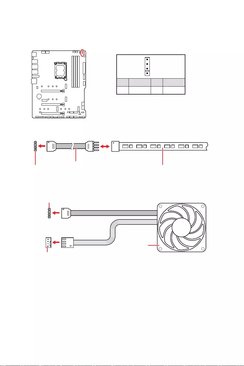
JRAINBOW1~3: Addressable RGB LED connectors
The JRAINBOW connectors allow you to connect the WS2812B Individually
Addressable RGB LED strips 5V.
JRAINBOW
connector
JRAINBOW connector
System Fan connector
JRainbow
extension cable WS2812B Individually
Addressable RGB LED strips 5V
1
1 +5V 2 Data
3 No Pin 4 Ground
Addressable RGB LED Strip Connection
Addressable RGB LED Fan Connection
Addressable RGB LED Fan
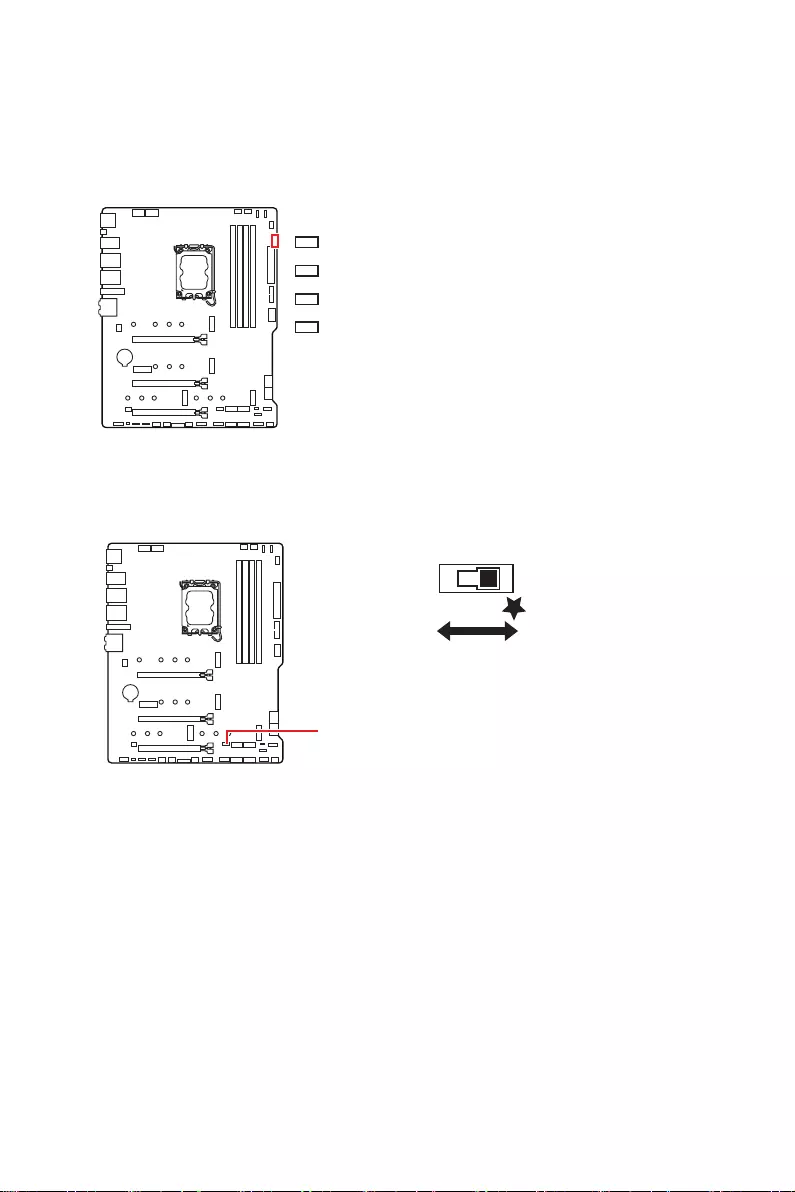
46 Onboard LEDs
EZ Debug LED
These LEDs indicate the debug status of the motherboard.
CPU — indicates CPU is not detected or fail.
DRAM — indicates DRAM is not detected or fail.
VGA — indicates GPU is not detected or fail.
BOOT — indicates the booting device is not detected
or fail.
Onboard LEDs
LED_SW1: EZ LED Control
This switch is used to switch on/ off all the LEDs of motherboard.
LED_SW1
LED_OFF LED_ON
(Default)

47
Installing OS, Drivers & MSI Center
Installing OS, Drivers & MSI Center
Please download and update the latest utilities and drivers at www.msi.com
Installing Windows 10/ Windows 11
1. Power on the computer.
2. Insert the Windows 10/ Windows 11 installation disc/USB into your computer.
3. Press the Restart button on the computer case.
4. Press F11 key during the computer POST (Power-On Self Test) to get into Boot
Menu.
5. Select the Windows 10/ Windows 11 installation disc/USB from the Boot Menu.
6. Press any key if screen shows Press any key to boot from CD or DVD… message.
If not, please skip this step.
7. Follow the instructions on the screen to install Windows 10/ Windows 11.
Installing Drivers
1. Start up your computer in Windows 10/ Windows 11.
2. Insert MSI® USB Drive into the USB port.
3. Click the Select to choose what happens with this disc pop-up notification, then
select Run DVDSetup.exe to open the installer. If you turn off the AutoPlay feature
from the Windows Control Panel, you can still manually execute the DVDSetup.exe
from the root path of the MSI USB Drive.
4. The installer will find and list all necessary drivers in the Drivers/Software tab.
5. Click the Install button in the lower-right corner of the window.
6. The drivers installation will then be in progress, after it has finished it will prompt
you to restart.
7. Click OK button to finish.
8. Restart your computer.
MSI Center
MSI Center is an application that helps you easily optimize game settings and smoothly
use content creation softwares. It also allows you to control and synchronize LED
light effects on PCs and other MSI products. With MSI Center, you can customize ideal
modes, monitor system performance, and adjust fan speed.
MSI Center User Guide
If you would like to know more information about MSI Center, please
refer to
http://download.msi.com/manual/mb/MSICENTER.pdf
or scan the QR code to access.
⚠
Important
Functions may vary depending on the product you have.

48 UEFI BIOS
UEFI BIOS
MSI UEFI BIOS is compatible with UEFI (Unified Extensible Firmware Interface)
architecture. UEFI has many new functions and advantages that traditional BIOS
cannot achieve, and it will completely replace BIOS in the future. The MSI UEFI
BIOS uses UEFI as the default boot mode to take full advantage of the new chipset’s
capabilities.
⚠
Important
The term BIOS in this user guide refers to UEFI BIOS unless otherwise noted.
UEFI advantages
∙Fast booting — UEFI can directly boot the operating system and save the BIOS self-
test process. And also eliminates the time to switch to CSM mode during POST.
∙Supports for hard drive partitions larger than 2 TB.
∙Supports more than 4 primary partitions with a GUID Partition Table (GPT).
∙Supports unlimited number of partitions.
∙Supports full capabilities of new devices — new devices may not provide backward
compatibility.
∙Supports secure startup — UEFI can check the validity of the operating system to
ensure that no malware tampers with the startup process.
Incompatible UEFI cases
∙32-bit Windows operating system — this motherboard supports only Windows 10/
Windows 11 64-bit operating system.
∙Older graphics card — the system will detect your graphics card. When display a
warning message There is no GOP (Graphics Output protocol) support detected in
this graphics card.
⚠
Important
We recommend that you to replace with a GOP/UEFI compatible graphics card or
using integrated graphics from CPU for having normal function.
How to check the BIOS mode?
1. Power on your computer.
2. Press Delete key, when the Press DEL key to enter Setup Menu, F11 to enter
Boot Menu message appears on the screen during the boot process.
3. After entering the BIOS, you can check the BIOS Mode at the top of the screen.
BIOS Mode: UEFI

49
UEFI BIOS
BIOS Setup
The default settings offer the optimal performance for system stability in normal
conditions. You should always keep the default settings to avoid possible system
damage or failure booting unless you are familiar with BIOS.
⚠
Important
∙
BIOS items are continuously update for better system performance. Therefore, the
description may be slightly different from the latest BIOS and should be for reference
only. You could also refer to the HELP information panel for BIOS item description.
∙
The BIOS screens, options and settings will vary depending on your system.
Entering BIOS Setup
Press Delete key, when the Press DEL key to enter Setup Menu, F11 to enter Boot
Menu message appears on the screen during the boot process.
Function key
F1: General Help list
F2: Add/ Remove a favorite item
F3: Enter Favorites menu
F4: Enter CPU Specifications menu
F5: Enter Memory-Z menu
F6: Load optimized defaults
F7: Switch between Advanced mode and EZ mode
F8: Load Overclocking Profile
F9: Save Overclocking Profile
F10: Save Change and Reset*
F12: Take a screenshot and save it to USB flash drive (FAT/ FAT32 format only).
Ctrl+F: Enter Search page
* When you press F10, a confirmation window appears and it provides the modification
information. Select between Yes or No to confirm your choice.
BIOS User Guide
If you’d like to know more instructions on setting up the BIOS, please
refer to
http://download.msi.com/manual/mb/Intel600BIOS.pdf
or scan the QR code to access.
50 UEFI BIOS
Resetting BIOS
You might need to restore the default BIOS setting to solve certain problems. There
are several ways to reset BIOS:
∙Go to BIOS and press F6 to load optimized defaults.
∙Short the Clear CMOS jumper on the motherboard.
⚠
Important
Be sure the computer is off before clearing CMOS data. Please refer to the Clear
CMOS jumper section for resetting BIOS.
Updating BIOS
Updating BIOS with M-FLASH
Before updating:
Please download the latest BIOS file that matches your motherboard model from MSI
website. And then save the BIOS file into the USB flash drive.
Updating BIOS:
1. Switch to the target BIOS ROM by Multi-BIOS switch. Please skip this step if your
motherboard doesn‘t has this switch.
2. Insert the USB flash drive that contains the update file into the USB port.
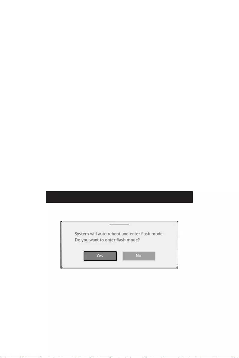
3. Please refer the following methods to enter flash mode.
▪Reboot and press Ctrl + F5 key during POST and click on Yes to reboot the
system.
Press <Ctrl+F5> to activate M-Flash for BIOS update.
▪Reboot and press Del key during POST to enter BIOS. Click the M-FLASH button
and click on Yes to reboot the system.
4. Select a BIOS file to perform the BIOS update process.
5. When prompted click on Yes to start recovering BIOS.
6. After the flashing process is 100% completed, the system will reboot
automatically.

51
UEFI BIOS
Updating the BIOS with MSI Center
Before updating:
∙Make sure the LAN driver is already installed and the internet connection is set
properly.
∙Please close all other application software before updating the BIOS.
To update BIOS:
1. Install and launch MSI Center and go to Support page.
2. Select Live Update and click on Advance button.
3. Select the BIOS file and click on Install button.
4. The installation reminder will appear, then click the Install button on it.
5. The system will automatically restart to update BIOS.
6. After the flashing process is 100% completed, the system will restart
automatically.
Updating BIOS with Flash BIOS Button
1. Please download the latest BIOS file that matches your motherboard model from
the MSI® website.
2. Rename the BIOS file to MSI.ROM, and save it to the root of the USB storage
device.
3. Connect the power supply to CPU_PWR1 and ATX_PWR1. (No need to install CPU
and memory.)
4. Plug the USB storage device that contains the MSI.ROM file into the Flash BIOS
Port on the rear I/O panel.
5. Press the Flash BIOS Button to flash BIOS, and the LED starts flashing.
6. The LED will be turned off when the process is completed.
RAID Configuration
The introduction of RAID levels and types are as below:
RAID 0 breaks the data into blocks which are written to separate hard drives.
Spreading the hard drive I/O load across independent channels greatly
improves I/O performance.
RAID 1 provides data redundancy by mirroring data between the hard drives and
provides enhanced read performance.
RAID 5 provides data striping at the byte level and also stripe error correction
information. This results in excellent performance and good fault tolerance.
RAID 10 uses four hard drives to create a combination of RAID 0 and 1 by forming a
RAID 0 array from two RAID 1 arrays.
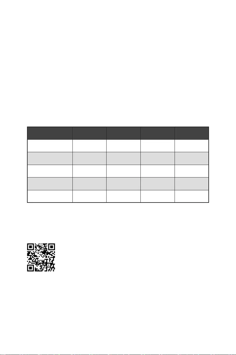
RAID level comparison
RAID 0 RAID 1 RAID 5 RAID 10
Minimum # drives 2 2 3 4
Data protection None Excellent Excellent Excellent
Read performance Excellent OK Good OK
Write performance Excellent Good OK Good
Capacity utilization 100% 50% 67%~(1-1/n) 50%
⚠
Important
All the information/ volumes/ pictures listed in your system might differ from the
illustrations in this appendix.
Intel RAID User Guide
If you’d like to know more instructions on how to set up Intel RAID,
please refer to
http://download.msi.com/manual/mb/IntelRAID600.pdf
or scan the QR code to access.
52 RAID Configuration
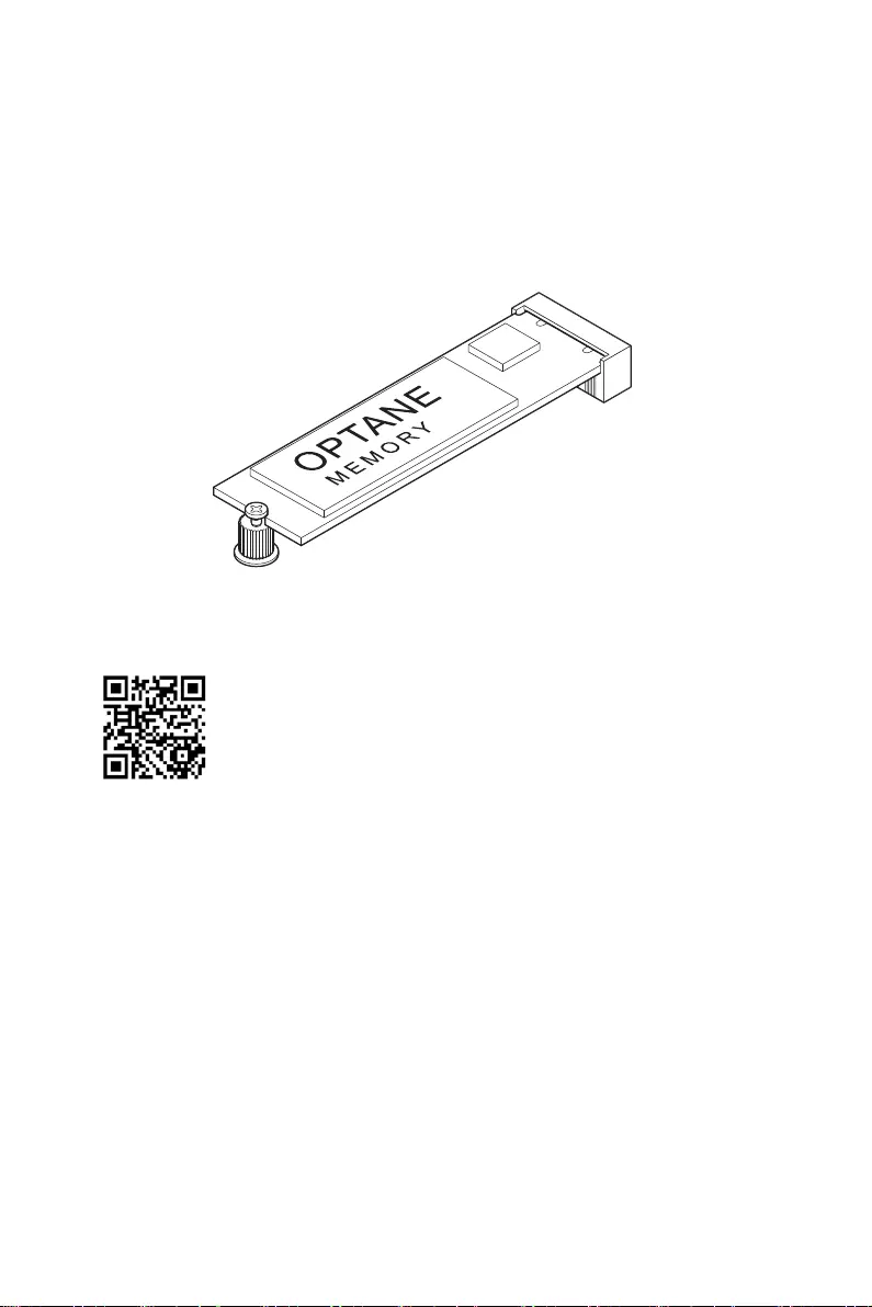
Intel® Optane™ Memory Configuration
Intel® Optane™ memory is a technology which allows the system to access the data
more quickly. It enables the computer to store commonly used data and programs,
and keeps them even after powering off the computer. Before you start to install Intel®
Optane™ memory, please note that it requires Windows 10 64-bit operating system.
Intel® Optane™ Memory User Guide
If you’d like to know more instructions on how to enable or remove
Intel® Optane™ Memory, please refer to
http://download.msi.com/manual/mb/Optane600.pdf
or scan the QR code to access.
⚠
WARNING
After you enable Intel® Optane™ memory, please note the following to prevent damage
to your operating system.
∙
DO NOT revert back to older version of the BIOS.
∙
DO NOT remove the Intel® Optane™ memory module.
∙
DO NOT replace the CPU that is not supported by Intel® Optane™ Memory.
53
Intel® Optane™ Memory Configuration

Troubleshooting
Before sending the motherboard for RMA
repair, try to go over troubleshooting
guide first to see if your got similar
symptoms as mentioned below.
The power is not on.
∙Connect the AC power cord to an
electrical outlet securely.
∙Check if all ATX power connectors
like ATX_PWR1, CPU_PWR1 are
connected from the power supply to the
motherboard?
∙Some power supply units have a power
button on the rear side, make sure the
button is turned on.
∙Check if the power switch cable is
connected to JFP1 pin header properly.
∙Verify the Clear CMOS jumper JBAT1 is
set to Keep DATA.
∙Test with another known working
power supply of equal or greater
wattage.
The power is on, but no signal to
monitor
∙Connect the monitor power cord to a
electrical outlet securely.
∙Make sure the monitor is turned on.
∙Select different inputs on the monitor.
∙If 3 long beeps are heard, remove all
memory modules and try to install only
one memory module in the DIMMA2 slot
first and then restart the computer.
∙If 1 long 2 short beeps are heard,
remove and reinstall the graphics card
and then restart the computer.
∙Test with another known working
graphics card.
The computer does not boot after
updating the BIOS
∙Clear the CMOS.
∙Use the secondary BIOS to bootup the
system (Only for motherboard with Dual
BIOS)
Lost BIOS password
∙Clear the CMOS, but that will cause
you to lose all customized settings in the
BIOS.
There is no audio
∙Adjust the volume.
∙Connect the speakers/headphones to
audio ports on the motherboard rear IO
panel.
∙Remove secondary speakers/
headphones, HDMI cables, USB audio
devices.
∙Test with another known working
speaker or headphone.
There is no network
∙Make sure the network chipset driver
has been installed.
∙Verify if the network cable is properly
connected and make sure the LAN port
LEDs are properly illuminated.
∙Verify your TCP/IP settings.
∙Restart or reset your router.
∙Test with another known working LAN
cable.
The USB device is not working
∙Make sure your USB drive driver has
been installed.
∙Verify if USB device is listed in
Windows® Device Manager.
∙Connect the USB device to other USB
port on the motherboard rear IO panel.
54 Troubleshooting
i
Regulatory Notices
Regulatory Notices
FCC Compliance Statement
Note: This equipment has been tested and found to
comply with the limits for a Class B digital device,
pursuant to part 15 of the FCC Rules. These limits are
designed to provide reasonable protection against
harmful interference in a residential installation. This
equipment generates, uses and can radiate radio
frequency energy and, if not installed and used in
accordance with the instructions, may cause harmful
interference to radio communications. However, there
is no guarantee that interference will not occur in a
particular installation. If this equipment does cause
harmful interference to radio or television reception,
which can be determined by turning the equipment
off and on, the user is encouraged to try to correct the
interference by one or more of the following measures:
yReorient or relocate the receiving antenna.
yIncrease the separation between the equipment
and receiver.
yConnect the equipment into an outlet on a circuit
different from that to which the receiver is
connected.
yConsult the dealer or an experienced radio/TV
technician for help.
Caution: Changes or modifications not expressly
approved by the party responsible for compliance could
void the user’s authority to operate the equipment.
Tested to comply with FCC standards
FOR HOME OR OFFICE USE
This device complies with part 15 of the FCC Rules.
Operation is subject to the following two conditions:
(1) This device may not cause harmful interference,
and (2) this device must accept any interference
received, including interference that may cause
undesired operation.
CE Conformity
Products bearing the CE marking comply
with one or more of the following EU
Directives as may be applicable:
RED 2014/53/EU; Low Voltage Directive 2014/35/EU;
EMC Directive 2014/30/EU; RoHS Directive 2011/65/EU.
Compliance with these directives is assessed using
applicable European Harmonized Standards.
The point of contact for regulatory matters is MSI,
MSI-NL Eindhoven 5706 5692 ER Son.
KC인증서
yMAG Z690 TOMAHAWK WIFI
yMAG Z690 TORPEDO
クラスB情報技術装置
VCCI-B
C-Tick Compliance
Battery Information
European Union:
Batteries, battery packs, and
accumulators should not be disposed of as
unsorted household waste. Please use the
public collection system to return, recycle,
or treat them in compliance with the local
regulations.
Taiwan:
For better environmental protection,
waste batteries should be collected
separately for recycling or special
disposal.
California, USA:
The button cell battery may contain
perchlorate material and requires special
handling when recycled or disposed of in
California.
For further information please visit:
http://www.dtsc.ca.gov/hazardouswaste/perchlorate/
CAUTION: There is a risk of explosion, if battery is
incorrectly replaced.
Replace only with the same or equivalent type
recommended by the manufacturer.
Chemical Substances Information
In compliance with chemical substances regulations,
such as the EU REACH Regulation (Regulation EC
No. 1907/2006 of the European Parliament and the
Council), MSI provides the information of chemical
substances in products at:
https://storage-asset.msi.com/html/popup/csr/
evmtprtt_pcm.html
Environmental Policy
yThe product has been designed to
enable proper reuse of parts and
recycling and should not be thrown
away at its end of life.
yUsers should contact the local
authorized point of collection for recycling and
disposing of their end-of-life products.
yVisit the MSI website and locate a nearby distributor
for further recycling information.
yUsers may also reach us at gpcontdev@msi.com for
information regarding proper Disposal, Take-back,
Recycling, and Disassembly of MSI products.
R-R-MSI-30-7D32
R-R-MSI-20-7D32

ii Regulatory Notices
WEEE (Waste Electrical and
Electronic Equipment) Statement
ENGLISH
To protect the global environment and as
an environmentalist, MSI must remind
you that…
Under the European Union (“EU”)
Directive on Waste Electrical and
Electronic Equipment, Directive 2002/96/
EC, which takes effect on August 13,
2005, products of “electrical and electronic equipment”
cannot be discarded as municipal wastes anymore, and
manufacturers of covered electronic equipment will
be obligated to take back such products at the end of
their useful life. MSI will comply with the product take
back requirements at the end of life of MSI-branded
products that are sold into the EU. You can return
these products to local collection points.
DEUTSCH
Hinweis von MSI zur Erhaltung und Schutz unserer
Umwelt
Gemäß der Richtlinie 2002/96/EG über Elektro- und
Elektronik-Altgeräte dürfen Elektro- und Elektronik-
Altgeräte nicht mehr als kommunale Abfälle entsorgt
werden. MSI hat europaweit verschiedene Sammel-
und Recyclingunternehmen beauftragt, die in die
Europäische Union in Verkehr gebrachten Produkte,
am Ende seines Lebenszyklus zurückzunehmen.
Bitte entsorgen Sie dieses Produkt zum gegebenen
Zeitpunkt ausschliesslich an einer lokalen
Altgerätesammelstelle in Ihrer Nähe.
FRANÇAIS
En tant qu’écologiste et afin de protéger
l’environnement, MSI tient à rappeler ceci…
Au sujet de la directive européenne (EU) relative aux
déchets des équipement électriques et électroniques,
directive 2002/96/EC, prenant effet le 13 août 2005, que
les produits électriques et électroniques ne peuvent
être déposés dans les décharges ou tout simplement
mis à la poubelle. Les fabricants de ces équipements
seront obligés de récupérer certains produits en fin
de vie. MSI prendra en compte cette exigence relative
au retour des produits en fin de vie au sein de la
communauté européenne. Par conséquent vous pouvez
retourner localement ces matériels dans les points
de collecte.
РУССКИЙ
ESPAÑOL
MSI como empresa comprometida con la protección
del medio ambiente, recomienda:
Bajo la directiva 2002/96/EC de la Unión Europea
en materia de desechos y/o equipos electrónicos,
con fecha de rigor desde el 13 de agosto de 2005,
los productos clasificados como “eléctricos y
equipos electrónicos” no pueden ser depositados
en los contenedores habituales de su municipio, los
fabricantes de equipos electrónicos, están obligados
a hacerse cargo de dichos productos al termino de
su período de vida. MSI estará comprometido con los
términos de recogida de sus productos vendidos en
la Unión Europea al final de su periodo de vida. Usted
debe depositar estos productos en el punto limpio
establecido por el ayuntamiento de su localidad o
entregar a una empresa autorizada para la recogida de
estos residuos.
NEDERLANDS
Om het milieu te beschermen, wil MSI u eraan
herinneren dat….
De richtlijn van de Europese Unie (EU) met betrekking
tot Vervuiling van Electrische en Electronische
producten (2002/96/EC), die op 13 Augustus 2005 in
zal gaan kunnen niet meer beschouwd worden als
vervuiling. Fabrikanten van dit soort producten worden
verplicht om producten retour te nemen aan het
eind van hun levenscyclus. MSI zal overeenkomstig
de richtlijn handelen voor de producten die de
merknaam MSI dragen en verkocht zijn in de EU. Deze
goederen kunnen geretourneerd worden op lokale
inzamelingspunten.
SRPSKI
vas podesti da…
EC, koja stupa na snagu od 13. Avgusta 2005, proizvodi
proizvoda kojima je istekao vek trajanja, koji imaju MSI
vratiti na lokalnim mestima za prikupljanje.
POLSKI
odpadów produktów elektrycznych i elektronicznych
(sprzedawane na terenie Unii Europejskiej) wycofywane
wyznaczonych punktach zbiorczych.
TÜRKÇE

iii
Regulatory Notices
ČESKY
EC platné od 13. srpna 2005 je zakázáno likvidovat
komunálním odpadu a výrobci elektronických
MAGYAR
Annak érdekében, hogy környezetünket megvédjük,
Önt, hogy …
Az Európai Unió („EU”) 2005. augusztus 13-án hatályba
hulladékairól szóló 2002/96/EK irányelve szerint
az elektromos és elektronikus berendezések
és az ilyen elektronikus berendezések gyártói
kötelessé válnak az ilyen termékek visszavételére
azok hasznos élettartama végén. Az MSI betartja a
termékvisszavétellel kapcsolatos követelményeket
az MSI márkanév alatt az EU-n belül értékesített
termékek esetében, azok élettartamának végén. Az
ITALIANO
Per proteggere l’ambiente, MSI, da sempre amica della
natura, ti ricorda che….
In base alla Direttiva dell’Unione Europea (EU) sullo
Smaltimento dei Materiali Elettrici ed Elettronici,
Direttiva 2002/96/EC in vigore dal 13 Agosto 2005,
prodotti appartenenti alla categoria dei Materiali
Elettrici ed Elettronici non possono più essere eliminati
come rifiuti municipali: i produttori di detti materiali
saranno obbligati a ritirare ogni prodotto alla fine
del suo ciclo di vita. MSI si adeguerà a tale Direttiva
ritirando tutti i prodotti marchiati MSI che sono stati
venduti all’interno dell’Unione Europea alla fine del
loro ciclo di vita. È possibile portare i prodotti nel più
vicino punto di raccolta
日本JIS C 0950材質宣言
https://storage-asset.msi.com/html/popup/csr/
cemm_jp.html
India RoHS
This product complies with the “India E-waste
(Management and Handling) Rule 2011” and prohibits
use of lead, mercury, hexavalent chromium,
polybrominated biphenyls or polybrominated diphenyl
ethers in concentrations exceeding 0.1 weight % and
0.01 weight % for cadmium, except for the exemptions
set in Schedule 2 of the Rule.
Türkiye EEE yönetmeliği
Україна обмеження на наявність
небезпечних речовин
Việt Nam RoHS
Wireless Radio Use
This device is restricted to indoor use when operating
in the 2.4GHz, 5GHz, 6GHz frequency band.
Cet appareil doit être utilisé à l’intérieur.
NCC無線設備警告聲明
Products with radio functionality (EMF)
This product incorporates a radio transmitting
and receiving device. For computers in normal
use, a separation distance of 20 cm ensures that
radio frequency exposure levels comply with EU
requirements. Products designed to be operated
at closer proximities, such as tablet computers,
comply with applicable EU requirements in typical
operating positions. Products can be operated without
maintaining a separation distance unless otherwise
indicated in instructions specific to the product.
Restrictions for products with radio functionality
CAUTION: IEEE 802.11x wireless LAN with
5.15–5.35 GHz frequency band is restricted
for indoor use only in all European Union
member states, EFTA (Iceland, Norway,
Liechtenstein), and most other European
countries (e.g., Switzerland, Turkey, Republic of
Serbia). Using this WLAN application outdoors might
lead to interference issues with existing radio services.
Radio frequency bands and maximum power levels
Features: Wi-Fi 6E, BT
Frequency Range:
2412~2484MHz, 5150~5350MHz (RLAN 1),
5470~5725MHz (RLAN 2), 5725~5875MHz (RLAN 3),
5875~5925MHz (RLAN 4), 5925~6425MHz
Max Power Level:
2.4 GHz: 20dBm; 5 GHz: 23dBm; 6 GHz: 23dBm
iv Regulatory Notices
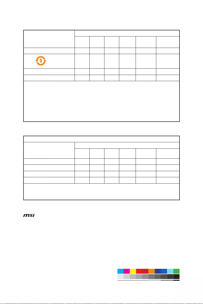
MS-7D32主板产品中有害物质的名称及含量
(Pb)
(Hg)
(Cd)
(Cr(VI))
(PBB)
(PBDE)
限用物質含有情況標示聲明書
(Pb)
(Hg)
(Cd)
(Cr+6)
(PBB)
(PBDE)
Copyright
Micro-Star Int’l Co.,Ltd.
Copyright © 2021 All rights reserved.
The MSI logo used is a registered trademark of
Micro-Star Int’l Co., Ltd. All other marks and names
mentioned may be trademarks of their respective
owners. No warranty as to accuracy or completeness is
expressed or implied. MSI reserves the right to make
changes to this document without prior notice.
Revision History
Version 2.0&3.0, 2021/10, First release.
Technical Support
If a problem arises with your system and no solution
can be obtained from the user guide, please
contact your place of purchase or local distributor.
Alternatively, please try the following help resources
for further guidance.
yVisit the MSI website for technical guide, BIOS
updates, driver updates, and other information:
http://www.msi.com
yRegister your product at: http://register.msi.com
MSI MAG Z690 TOMAHAWK WIFI DDR4

View the manual for the MSI MAG Z690 TOMAHAWK WIFI DDR4 here, for free. This manual comes under the category lenses and has been rated by 1 people with an average of a 9.8.
This manual is available in the following languages: English. Do you have a question about the MSI MAG Z690 TOMAHAWK WIFI DDR4 or do you need help?
Ask your question here
Index
- Safety Information
- Specifications
- Package contents
- Rear I/O Panel
- Overview of Components
- Onboard LEDs
- Installing OS, Drivers & MSI Center
- UEFI BIOS
- Sicherheitshinweis
- Spezifikationen
- Packungsinhalt
- Rückseite E/A
- Übersicht der Komponenten
- Onboard LEDs
- Installation von OS, Treibern & MSI Center
- UEFI BIOS
- Informations de sécurité
- Spécifications
- Contenu
- Panneau arrière Entrée/Sortie
- Vue d’ensemble des composants
- LED embarquées
- Installer OS, Pilotes et MSI Center
- UEFI BIOS
- Безопасное использование продукции
- Технические характеристики
- Комплект поставки
- Задняя панель портов ввода/ вывода
- Компоненты материнской платы
- Встроенные индикаторы
- Установка ОС, драйверов и MSI Center
- UEFI BIOS
- 安全に関する注意事項
- 仕様
- パッケージの内容
- リアI/Oパネル
- コンポーネントの概要
- オンボードLED
- OS、ドライバーおよびMSI Centerのインストール
- UEFI BIOS
- 안전 지침
- 사양
- 제품 내용물
- 후면 I/O 패널
- 구성품 개요
- 온보드 LEDs
- OS, 드라이버 & MSI 센터 설치하기
- UEFI BIOS
Product Images (7)

MSI MAG Z690 TOMAHAWK WIFI DDR4 specifications
Below you will find the product specifications and the manual specifications of the MSI MAG Z690 TOMAHAWK WIFI DDR4.
The MSI MAG Z690 TOMAHAWK WIFI DDR4 is a motherboard specifically designed to support Intel processors. With a LGA 1700 socket, it is compatible with Intel Celeron and Intel Pentium Gold processor series. This motherboard features four DIMM memory slots, supporting memory clock speeds of 2666 and 2933 MHz. It has a maximum internal memory capacity of 128 GB, offering ample storage for demanding tasks.
In terms of storage, the MSI MAG Z690 TOMAHAWK WIFI DDR4 supports both HDD and SSD drive types. It includes M.2 and SATA III interfaces, providing flexibility in choosing the storage drive of your preference. Additionally, this motherboard supports RAID levels 0, 1, 5, and 10, allowing users to configure their storage setup for enhanced performance or data redundancy.
For connectivity, this motherboard offers two USB 2.0 connectors and one USB 3.2 Gen 1 (3.1 Gen 1) connector. These ports provide fast data transfer speeds and enable the connection of various peripheral devices.
Furthermore, the MSI MAG Z690 TOMAHAWK WIFI DDR4 supports Crossfire parallel processing technology, facilitating multi-GPU setups for enhanced graphics performance.
Overall, the MSI MAG Z690 TOMAHAWK WIFI DDR4 is a feature-rich motherboard designed for users seeking reliable performance and expandability. With its compatibility with Intel processors, support for various storage drives, and connectivity options, it provides a solid foundation for building a high-performance system.
Processor manufacturer
Intel
Supported memory types
DDR4-SDRAM
Supported storage drive types
HDD & SSD
Parallel processing technology support
Crossfire
General
| Brand | MSI |
| Model | MAG Z690 TOMAHAWK WIFI DDR4 | MAG Z690 TOMAHAWK WIFI DDR4 |
| Product | lens |
| EAN | 4719072886585 |
| Language | English |
| Filetype | User manual (PDF) |
Processor
| Processor manufacturer | Intel |
| Processor socket | LGA 1700 |
| Compatible processor series | Intel Celeron, Intel Pentium Gold |
Memory
| Supported memory types | DDR4-SDRAM |
| Number of memory slots | 4 |
| Memory slots type | DIMM |
| Memory channels | Dual-channel |
| Supported memory clock speeds | 2666,2933 MHz |
| Maximum internal memory | 128 GB |
Storage controllers
| Supported storage drive types | HDD & SSD |
| Supported storage drive interfaces | M.2, SATA III |
| RAID levels | 0, 1,5, 10 |
Graphics
| Parallel processing technology support | Crossfire |
Internal I/O
| USB 2.0 connectors | 2 |
| USB 3.2 Gen 1 (3.1 Gen 1) connectors | 1 |
| USB 3.2 Gen 2 (3.1 Gen 2) connectors | 2 |
| Number of SATA III connectors | 6 |
| TPM connector | Yes |
| 12V power connector | Yes |
| RGB LED pin header | Yes |
| Front panel audio connector | Yes |
| ATX Power connector (24-pin) | Yes |
| CPU fan connector | Yes |
| Chassis intrusion connector | Yes |
Rear panel I/O ports
| USB 2.0 ports quantity | 2 |
| USB 3.2 Gen 1 (3.1 Gen 1) Type-A ports quantity | 2 |
| USB 3.2 Gen 2 (3.1 Gen 2) Type-A ports quantity | 3 |
| USB 3.2 Gen 2 (3.1 Gen 2) Type-C ports quantity | 0 |
| USB 3.2 Gen 2×2 Type-C ports quantity | 1 |
| USB 3.2 Gen 1 (3.1 Gen 1) Type-C ports quantity | 0 |
| Ethernet LAN (RJ-45) ports | 1 |
| VGA (D-Sub) ports quantity | 0 |
| HDMI ports quantity | 1 |
| DVI-D ports quantity | 0 |
| DisplayPorts quantity | 1 |
| DisplayPort version | 1.4 |
| S/PDIF out port | Yes |
| Microphone in | Yes |
| Headphone outputs | 1 |
Network
| Ethernet LAN | Yes |
| Ethernet interface type | 2.5 Gigabit Ethernet, Gigabit Ethernet |
| Wi-Fi | Yes |
| Top Wi-Fi standard | Wi-Fi 6 (802.11ax) |
| Wi-Fi standards | Wi-Fi 6 (802.11ax) |
| Bluetooth | Yes |
| Bluetooth version | 5.2 |
Features
| Component for | PC |
| Motherboard form factor | ATX |
| Motherboard chipset family | Intel |
| Motherboard chipset | Intel Z690 |
| Audio chip | Realtek ALC4080 |
| Audio output channels | 7.1 channels |
Expansion slots
| PCI Express x16 (Gen 3.x) slots | 1 |
| Number of M.2 (M) slots | 2 |
BIOS
| BIOS type | UEFI |
| BIOS memory size | 256 Mbit |
| System Management BIOS (SMBIOS) version | 3.4 |
Logistics data
| Harmonized System (HS) code | 84733020 |
Weight & dimensions
| Height | 73 mm |
| Width | 305 mm |
| Depth | 244 mm |
Other features
show more
Frequently Asked Questions
Can’t find the answer to your question in the manual? You may find the answer to your question in the FAQs about the MSI MAG Z690 TOMAHAWK WIFI DDR4 below.
How can I properly install the MSI MAG Z690 TOMAHAWK WIFI DDR4 onto my motherboard?
Ensure that the motherboard is powered off. Align the notches on the lens with the corresponding slots on the motherboard and gently push it in until it is securely seated. Finally, fasten the screws to secure the lens in place.
What is the optimal RAM configuration for the MSI MAG Z690 TOMAHAWK WIFI DDR4?
The lens supports dual-channel DDR4 memory. For optimal performance, it is recommended to install memory modules in pairs, using slots 1 and 3 or slots 2 and 4.
How can I connect additional devices, such as storage drives or graphics cards, to the MSI MAG Z690 TOMAHAWK WIFI DDR4?
The lens provides multiple expansion slots. Consult your motherboard manual to identify the appropriate slots for your specific devices. Connect the devices firmly and ensure they are securely seated to ensure proper functionality.
How can I access the BIOS settings on the MSI MAG Z690 TOMAHAWK WIFI DDR4?
To access the BIOS, power on or restart your computer and repeatedly press the «Delete» key until the BIOS settings menu appears. From there, you can make adjustments and save any changes before exiting the BIOS.
How can I update the BIOS firmware on the MSI MAG Z690 TOMAHAWK WIFI DDR4?
Visit the official MSI website and locate the page for your specific motherboard model. Download the latest BIOS update file and save it to a USB flash drive. Restart your computer and enter the BIOS settings. Navigate to the «Flash BIOS» section and follow the on-screen instructions to select and apply the downloaded BIOS update from the USB flash drive. Ensure that your computer remains powered on during the update process.
Does the MSI MAG Z690 TOMAHAWK WIFI DDR4 support Intel processors?
Yes, the MSI MAG Z690 TOMAHAWK WIFI DDR4 is compatible with Intel processors, specifically Intel Celeron and Intel Pentium Gold. This allows users to choose from a variety of compatible CPUs for their build.
How many memory slots does the MSI MAG Z690 TOMAHAWK WIFI DDR4 have?
The MSI MAG Z690 TOMAHAWK WIFI DDR4 has 4 memory slots, providing users with the flexibility to install up to 4 memory modules for a maximum capacity of 128 GB. This allows for ample memory expansion and improved multitasking capabilities.
What types of storage drives are supported by the MSI MAG Z690 TOMAHAWK WIFI DDR4?
The MSI MAG Z690 TOMAHAWK WIFI DDR4 supports both HDD (Hard Disk Drive) and SSD (Solid State Drive) storage drive types. This versatility allows users to choose the storage option that best suits their needs, whether it’s for storage capacity or faster performance.
How many SATA III connectors does the MSI MAG Z690 TOMAHAWK WIFI DDR4 have?
The MSI MAG Z690 TOMAHAWK WIFI DDR4 has 6 SATA III connectors. This provides users with ample connectivity options for their SATA devices, such as hard drives and solid-state drives, allowing for easy expansion and storage management.
Does the MSI MAG Z690 TOMAHAWK WIFI DDR4 support RAID levels?
Yes, the MSI MAG Z690 TOMAHAWK WIFI DDR4 supports RAID levels 0, 1, 5, and 10. RAID (Redundant Array of Independent Disks) configurations offer enhanced data protection, improved performance, and increased storage capacity. This feature provides users with more flexibility in configuring their storage setup to meet their specific needs.
What is the weight of the MSI MAG Z690 TOMAHAWK WIFI DDR4?
The MSI MAG Z690 TOMAHAWK WIFI DDR4 has a weight of 1000 g.
What is the height of the MSI MAG Z690 TOMAHAWK WIFI DDR4?
The MSI MAG Z690 TOMAHAWK WIFI DDR4 has a height of 73 mm.
What is the width of the MSI MAG Z690 TOMAHAWK WIFI DDR4?
The MSI MAG Z690 TOMAHAWK WIFI DDR4 has a width of 305 mm.
What is the depth of the MSI MAG Z690 TOMAHAWK WIFI DDR4?
The MSI MAG Z690 TOMAHAWK WIFI DDR4 has a depth of 244 mm.
Is the manual of the MSI MAG Z690 TOMAHAWK WIFI DDR4 available in English?
Yes, the manual of the MSI MAG Z690 TOMAHAWK WIFI DDR4 is available in English .
Is your question not listed? Ask your question here
- June 4, 2024
- MSI
MAG Z690 TOMAHAWK WIFI Motherboard
**User Guide
**
Generated 2021-11-08, check for the latest version at
www.msi.com/datasheet. The information
provided in this document is intended for informational purposes only and is
subject to change without notice.
MOTHERBOARDS
MAG Z690 TOMAHAWK WIFI
CONQUER THE BATTLEFIELD
SPECIFICATIONS
| Model Name | MAG Z690 TOMAHAWK WIFI |
|---|---|
| CPU Support | Supports 12th Gen Intel® CoreTM Processors, Pentium® Gold and |
Celeron® Processors
CPU Socket| LGA 1700
Chipset| Intel® Z690 Chipset
Graphics Interface| 1x PCIe 5.0 x16 slot, 1x PCIe 3.0 x16 slot Supports AMD®
CrossFireTM Technology
Display Interface| Support 4K@60Hz as specified in HDMI 2.1, DisplayPort 1.4
Requires Processor Graphics
Memory Support| 4 DIMMs, Dual Channel DDR5-6400+ (OC)
Expansion Slots| 1x PCIe 3.0 x16 slot, 1x PCIe 3.0 x1 slot
Storage| 3x M.2 Gen4 x4 64Gbps slots, 1x M.2 Gen3 x4 32Gbps slot, Support
Intel® OptaneTM Technology, 6x SATA 6Gb/s ports
USB ports| 1x USB 3.2 Gen 2×2 20Gbps (Type-C), 4x USB 3.2 Gen 2 10Gbps (3
Type-A + 1 Type-C), 4x USB 3.2 Gen 1 5Gbps (Type-A), 6x USB 2.0
LAN| 1x Intel® I225-V 2.5G LAN
Wireless / Bluetooth| Intel® Wi-Fi 6E module, Bluetooth 5.2
Audio| 8-Channel (7.1) HD Audio with Audio Boost 5
FEATURES
Quadruple M.2 Connectors
Onboard quadruple M.2 connectors for maximum storage performance.
M.2 Shield FROZR
M.2 thermal accessory. Keeps M.2 SSDs safe while preventing throttling, making
them run faster.
Lightning Gen 5
The latest PCIe 5.0 solution with up to 128GB/s bandwidth for maximum transfer
speed.
Latest DDR5 Memory
A huge step of DDR performance enhancement with the latest DDR5 memory and MSI
Memory Boost technology.
Wi-Fi 6E
The latest wireless solution supports 6GHz spectrum, MU-MIMO, and BSS color
technology, delivering speeds up to 2400Mbps.
2.5G Network Solution
Features premium 2.5G LAN with LAN manager to deliver a better network
experience.
Lightning USB 20G
Built-in USB 3.2 Gen 2×2 port, offers 20Gbps transmission speed, 4X faster
than USB 3.2 Gen 1.
Memory Boost
Advanced technology to deliver pure data signals for the best performance,
stability, and compatibility.
Audio Boost 5
Isolated audio with a high-quality audio processor & amp for the most
immersive gaming experience
CONNECTIONS
1. DisplayPort 1.4
2. USB 2.0 Port
3. USB 3.2 Gen 2 10Gbps Type-A
4. 2.5G LAN Port
5. Wi-Fi / Bluetooth Antenna
6. HD Audio Connectors| 7. HDMI 2.1 Port
8. Flash BIOS Button
9. USB 3.2 Gen 1 5Gbps Type-A
10. USB 3.2 Gen 2 10Gbps Type-A
11. USB 3.2 Gen 2×2 20Gbps Type-C
12. Optical S/PDIF OUT
—|—
© 2021 Micro-Star Int’l Co.Ltd. MSI is a registered trademark of Micro-Star
Int’l Co.Ltd. All rights reserved. Intel, the Intel logo, the Intel Inside
logo, and Intel Core are trademarks of Intel Corporation or its subsidiaries
in the U.S. and/or other countries.
Generated 2021-11-08, check for the latest version
www.msi.com/datasheet. The information
provided in this document is intended for informational purposes only and is
subject to change without notice.
Read User Manual Online (PDF format)
Read User Manual Online (PDF format) >>
Download This Manual (PDF format)
Download this manual >>
I
Quick Start
Quick Start
Thank you for purchasing the MSI® MAG Z690 TOMAHAWK WIFI
DDR4 motherboard. This Quick Start section provides demonstration
diagrams about how to install your computer. Some of the
installations also provide video demonstrations. Please link to the
URL to watch it with the web browser on your phone or tablet. You
may have even link to the URL by scanning the QR code.
Kurzanleitung
Danke, dass Sie das MSI® MAG Z690 TOMAHAWK WIFI DDR4
Motherboard gewählt haben. Dieser Abschnitt der Kurzanleitung
bietet eine Demo zur Installation Ihres Computers. Manche
Installationen bieten auch die Videodemonstrationen. Klicken Sie
auf die URL, um diese Videoanleitung mit Ihrem Browser auf Ihrem
Handy oder Table anzusehen. Oder scannen Sie auch den QR Code
mit Ihrem Handy, um die URL zu öffnen.
Présentation rapide
Merci d’avoir choisi la carte mère MSI® MAG Z690 TOMAHAWK
WIFI DDR4. Ce manuel fournit une rapide présentation avec des
illustrations explicatives qui vous aideront à assembler votre
ordinateur. Des tutoriels vidéo sont disponibles pour certaines
étapes. Cliquez sur le lien fourni pour regarder la vidéo sur votre
téléphone ou votre tablette. Vous pouvez également accéder au lien
en scannant le QR code qui lui est associé.
Быстрый старт
MAG
Z690 TOMAHAWK WIFI DDR4
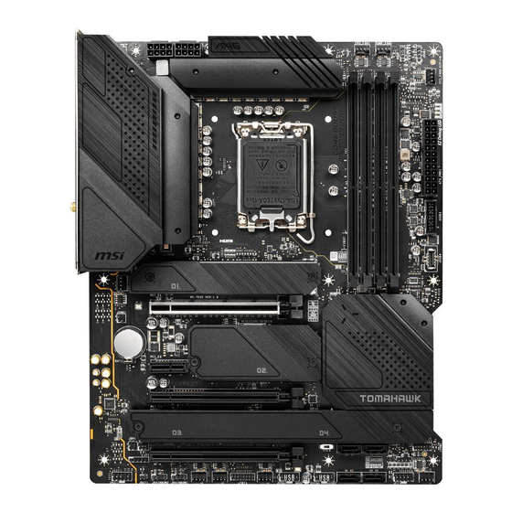
- Manuals
- Brands
- MSI Manuals
- Motherboard
- MAG Z690 TOMAHAWK
- User manual
-
Contents
-
Table of Contents
-
Bookmarks
MAG Z690 TOMAHAWK WIFI
MAG Z690 TORPEDO
Motherboard
User Guide
Benutzerhandbuch
Manuel d’utilisation
Руководство пользователя
取扱説明書
사용 명서
使用手冊
使用手册
I
Need help?
Do you have a question about the MAG Z690 TOMAHAWK WIFI and is the answer not in the manual?
Questions and answers
Related Manuals for MSI MAG Z690 TOMAHAWK WIFI
Summary of Contents for MSI MAG Z690 TOMAHAWK WIFI
-
Page 1
MAG Z690 TOMAHAWK WIFI MAG Z690 TORPEDO Motherboard User Guide Benutzerhandbuch Manuel d’utilisation Руководство пользователя 取扱説明書 사용 명서 使用手冊 使用手册… -
Page 2
English Deutsch Français Русский 日本語 한국어 繁體中文 簡体中文… -
Page 3
Sie auch den QR Code mit Ihrem Handy, um die URL zu öffnen. Présentation rapide Merci d’avoir choisi la carte mère MSI®. Ce manuel fournit une rapide présentation avec des illustrations explicatives qui vous aideront à assembler votre ordinateur. -
Page 4
Installing a Processor/ Installation des Prozessors/ Installer un processeur/ Установка процессора/ CPUの取り付け/ 프로세서 설치하기/ 安裝處理器/ 安装处理器 Youtube ⚽ https://youtu.be/KMf9oIDsGes 优酷 ⚽ https://v.youku.com/v_show/id_ XNTE5NDQwNDY2NA==.html… -
Page 5
Installing DDR5 memory/ Installation des DDR5-Speichers/ Installer une mémoire DDR5/ Установка памяти DDR5/ DDR5メ モリの取り付け/ DDR5 메모리 설치하기/ 安裝 DDR5 記憶體/ 安装 DDR5 内存 Youtube 优酷 ⚽ ⚽ https://v.youku.com/v_show/id_ https://youtu.be/XiNmkDNZcZk XNTE5NTg0NDM4NA==.html DIMMA1 DIMMA2 DIMMA2 DIMMA2 DIMMB2 DIMMB1 DIMMB2… -
Page 6
Connecting the Front Panel Header/ Anschließen der Frontpanel-Stiftleiste/ Connecter un connecteur du panneau avant/ Подключение разъемов передней панели/ フロントパネルヘッダーの接続/ 전면 패널 커넥터 연결하기/ 連接前置面板針腳/ 连接前置面板接头 Youtube 优酷 ⚽ ⚽ http://v.youku.com/v_show/id_XNjcyMTczMzM2.html http://youtu.be/DPELIdVNZUI Power LED Power Switch JFP1 Reserved HDD LED Reset Switch HDD LED + Power LED + HDD LED -… -
Page 7
Installing the Motherboard/ Installation des Motherboards/ Installer la carte mère/ Установка материнской платы/ マザー ボードの取り付け/ 메인보드 설치하기/ 安裝主機板/ 安装主板 Youtube ⚽ https://youtu.be/wWI6Qt51Wnc 优酷 ⚽ https://v.youku.com/v_show/id_ XNDUwMDUyNTkwOA==.html Torque: 3 kgf·cm* BAT1 *3 kgf·cm = 0.3 N·m = 2.6 lbf·in… -
Page 8
Connecting the Power Connectors/ Stromanschlüsse anschliessen/ Connecter les câbles du module d’alimentation/ Подключение разъемов питания/ 電源コネクターの接続/ 전원 커넥터 연결하기/ 插上電源接頭/ 连接电源接头 Youtube 优酷 ⚽ ⚽ http://youtu.be/gkDYyR_83I4 http://v.youku.com/v_show/id_XNDkzODU0MDQw.html ATX_PWR1 CPU_PWR2 CPU_PWR1 VIII… -
Page 9
Installing SATA Drives/ Installation der SATA-Laufwerke/ Installer le disque dur SATA/ Установка дисков SATA/ SATAド ライブの取り付け/ SATA 드라이브 설치하기/ 安裝 SATA 磁碟機/ 安 装 SATA 设备 Youtube ⚽ http://youtu.be/RZsMpqxythc 优酷 ⚽ http://v.youku.com/v_show/ id_XNDkzODU5MTky.html… -
Page 10
Installing a Graphics Card/ Einbau der Grafikkarte/ Installer une carte graphique/ Установка дискретной видеокарты/ グラ フィックスカードの取り付け/ 그래픽 카드 설치하기 / 安裝顯示卡/ 安装显卡 Youtube ⚽ http://youtu.be/mG0GZpr9w_A 优酷 ⚽ http://v.youku.com/v_show/ id_XNDkyOTc3MzQ4.html… -
Page 11
Connecting Peripheral Devices/ Peripheriegeräte/ Connecter un périphérique anschliessen/ Подключение периферийных устройств/ 周辺機器の接続/ 주변 장치 연결하기/ 連接周邊設備/ 连接外围设备 (MAG Z690 TOMAHAWK WIFI) -
Page 12
Power On/ Einschalten/ Mettre sous-tension/ Включение питания/ 通電/ 전원 켜기/ 啟動電源/ 开机… -
Page 13: Table Of Contents
Contents Safety Information ………………..3 Case stand-off notification ………………4 Avoid collision notification ………………4 Specifications ………………….5 Package contents ………………..12 Rear I/O Panel ………………… 13 LAN Port LED Status Table ……………… 13 Audio Ports Configuration ………………13 Realtek Audio Console ………………14 Overview of Components ………………
-
Page 14
Installing OS, Drivers & MSI Center …………..35 Installing Windows 10/ Windows 11 …………..35 Installing Drivers ………………..35 MSI Center ………………….35 UEFI BIOS ………………….36 BIOS Setup ………………….37 Entering BIOS Setup ………………… 37 BIOS User Guide ………………..37 Resetting BIOS …………………. -
Page 15: Safety Information
Safety Information ∙ The components included in this package are prone to damage from electrostatic discharge (ESD). Please adhere to the following instructions to ensure successful computer assembly. ∙ Ensure that all components are securely connected. Loose connections may cause the computer to not recognize a component or fail to start.
-
Page 16: Case Stand-Off Notification
Case stand-off notification To prevent damage to the motherboard, any unnecessary mounting stand-off between the motherboard circuits and the computer case is prohibited. The Case standoff keep out zone signs will be marked on the backside of motherboard (as shown below) to serve as a warning to user.
-
Page 17: Specifications
Specifications ∙ Supports 12th Gen Intel® Core™ Processors, Pentium® Gold and Celeron® Processors ∙ Processor socket LGA1700 * Please go to www.msi.com to get the newest support status as new processors are released. Chipset Intel® Z690 Chipset ∙ 4x DDR5 memory slots, supporting up to 128GB* ∙…
-
Page 18
Continued from previous column ∙ 6x SATA 6Gb/s ports (From Z690 chipset) ∙ 4x M.2 slots (Key M) ▪ M2_1 slot (From CPU) ▫ Supports up to PCIe 4.0 x4 ▫ Supports 2242/ 2260/ 2280/ 22110 storage devices ▪ M2_2 slot (From Z690 chipset) ▫… -
Page 19
Continued from previous column Realtek® ALC4080 Codec Audio ∙ 7.1-Channel High Definition Audio ∙ Supports S/PDIF output ∙ 1x Intel® I225V 2.5Gbps LAN controller Intel® Wi-Fi 6E ∙ The Wireless module is pre-installed in the M.2 (Key-E) slot ∙ Supports MU-MIMO TX/RX, 2.4GHz/ 5GHz/ 6GHz*(160MHz) Wi-Fi &… -
Page 20
Continued from previous column ∙ 1x EZ LED Control switch ∙ 1x 4-pin RGB LED connector LED Features ∙ 3x 3-pin RAINBOW LED connectors ∙ 4x EZ Debug LED ∙ 1x DisplayPort port ∙ 1x HDMI port ∙ 1x Flash BIOS button ∙… -
Page 21
Continued from previous column ∙ Drivers ∙ MSI Center ∙ Intel Extreme Tuning Utility ∙ MSI APP Player (BlueStacks) Software ∙ Open Broadcaster Software (OBS) ∙ CPU-Z MSI GAMING ∙ Google Chrome™, Google Toolbar, Google Drive ∙ Norton™ Internet Security Solution ∙… -
Page 22
Continued from previous column ∙ Audio ▪ Audio Boost 5 ∙ Network ▪ 2.5G LAN ▪ LAN Manager ▪ Intel Wi-Fi (For MAG Z690 TOMAHAWK WIFI) ∙ Cooling ▪ All Aluminum Design ▪ Extended Heatsink Design Special Features ▪ M.2 Shield Frozr ▪… -
Page 23
▪ 2oz Copper thickened PCB Special Features ∙ Protection ▪ PCI-E Steel Armor ▪ Pre-installed I/O Shielding ∙ Experience ▪ MSI Center ▪ Click BIOS 5 ▪ EZ M.2 Clip ▪ Flash BIOS Button ▪ Frozr AI Cooling ▪ EZ LED Control ▪… -
Page 24: Package Contents
Package contents Please check the contents of your motherboard package. It should contain: Motherboard MAG Z690 TOMAHAWK WIFI/ MAG Z690 TORPEDO Quick installation guide Documentation Application USB drive with drivers & utilities Cables SATA 6Gb/s cables (2 cables/pack) Wi-Fi antenna (For MAG Z690 TOMAHAWK WIFI) Case badge EZ M.2 clip (1 set/pack)
-
Page 25: Rear I/O Panel
Rear I/O Panel Flash BIOS port Audio Ports Wi-Fi Antenna USB 2.0 connectors Type-A 2.5Gbps DisplayPort USB 3.2 USB 3.2 USB 3.2 Optical Flash BIOS Gen 1 Gen 2 Gen 2×2 S/PDIF-Out Button (5Gbps) (10Gbps) (20Gbps) Type-A Type-A Type-C For MAG Z690 TOMAHAWK WIFI ∙…
-
Page 26: Realtek Audio Console
Realtek Audio Console After Realtek Audio Console is installed. You can use it to change sound settings to get better sound experience. Application Enhancement Device Selection Main Volume Connector Settings Jack Status ∙ Device Selection — allows you to select a audio output source to change the related options.
-
Page 27
Audio jacks to headphone and microphone diagram Audio jacks to stereo speakers diagram AUDIO INPUT Audio jacks to 7.1-channel speakers diagram AUDIO INPUT Rear Front Side Center/ Subwoofer Rear I/O Panel… -
Page 28
Installing antennas 1. Screw the antennas tight to the antenna connectors as shown below. 2. Orient the antennas. Rear I/O Panel… -
Page 29: Overview Of Components
Overview of Components JRAINBOW3 Processor Socket PUMP_FAN1 JRGB1 CPU_PWR1 CPU_PWR2 CPU_FAN1 SYS_FAN2 ATX_PWR1 JUSB3 JUSB4 M2_1 SYS_FAN1 DIMMB2 DIMMB1 PCI_E1 DIMMA2 DIMMA1 M2_2 SATA6 BAT1 SATA5 PCI_E2 M2_4 SATA1 PCI_E3 M2_3 SATA2 JCI1 JDASH1 JTPM1 PCI_E4 JFP2 LED_SW1 JAUD1 SYS_FAN3 JBAT1 JFP1 JRAINBOW2…
-
Page 30: Cpu Socket
∙ the CPU. ∙ Please retain the CPU protective cap after installing the processor. MSI will deal with Return Merchandise Authorization (RMA) requests if only the motherboard comes with the protective cap on the CPU socket. When installing a CPU, always remember to install a CPU heatsink. A CPU heatsink ∙…
-
Page 31: Dimm Slots
It is recommended to use a more efficient memory cooling system for full DIMMs ∙ installation or overclocking. The stability and compatibility of installed memory module depend on installed CPU ∙ and devices when overclocking. ∙ Please refer to www.msi.com for more information on compatible memory. Overview of Components…
-
Page 32: Pci_E1~4: Pcie Expansion Slots
Important ∙ If you install a large and heavy graphics card, you need to use a tool such as MSI Graphics Card Bolster to support its weight to prevent deformation of the slot. For a single PCIe x16 expansion card installation with optimum performance, using ∙…
-
Page 33: M2_1~4: M.2 Slots (Key M)
∙ Memory. M2_1 M2_2 M2_4 M2_3 For MAG Z690 TOMAHAWK WIFI M.2 slot installation 1. Loosen the screws of M.2 SHIELD FROZR heatsink. 2. Remove the M.2 SHIELD FROZR and remove the protective films from the thermal pads. M2_1 M2_2 M2_3&M2_4…
-
Page 34
3. If there is no EZ M.2 Clip installed, please install the supplied EZ M.2 Clip kit in the M.2 slot according to your SSD length. 4. Insert your M.2 SSD into the M.2 slot at a 30-degree angle. 5. Rotate the EZ M.2 Clip to fix the M.2 SSD. 30º… -
Page 35
For MAG Z690 TORPEDO M2_1, M2_3 & M2_4 slot installation 1. Loosen the screws of M.2 SHIELD FROZR heatsink. 2. Remove the M.2 SHIELD FROZR and remove the protective films from the thermal pads. M2_1 M2_3&M2_4 3. If there is no EZ M.2 Clip installed, please install the supplied EZ M.2 Clip kit in the M.2 slot according to your SSD length. -
Page 36
6. Put the M.2 SHIELD FROZR heatsink back in place and secure it. M2_2 slot installation 1. Secure the supplied M.2 standoff according to your M.2 SSD length if need. 2. Insert your M.2 SSD into the M.2 slot at a 30-degree angle. 3. -
Page 37: Sata1~6: Sata 6Gb/S Connectors
SATA1~6: SATA 6Gb/s Connectors These connectors are SATA 6Gb/s interface ports. Each connector can connect to one SATA device. SATA6 SATA4 SATA3 SATA5 SATA1 SATA2 ⚠ Important ∙ Please do not fold the SATA cable at a 90-degree angle. Data loss may result during transmission otherwise.
-
Page 38: Cpu_Pwr1~2, Atx_Pwr1: Power Connectors
CPU_PWR1~2, ATX_PWR1: Power Connectors These connectors allow you to connect an ATX power supply. CPU_PWR1~2 Ground +12V Ground +12V Ground +12V Ground +12V +3.3V +3.3V +3.3V -12V Ground Ground PS-ON# Ground Ground Ground ATX_PWR1 Ground Ground PWR OK 5VSB +12V +12V +3.3V Ground…
-
Page 39: Jdash1 : Tuning Controller Connector
JDASH1 : Tuning Controller connector This connector is used to connect an optional Tuning Controller module. No Pin MCU_SMB_SCL_M MCU_SMB_SDA_M VCC5 Ground JCI1: Chassis Intrusion Connector This connector allows you to connect the chassis intrusion switch cable. Normal Trigger the chassis (default) intrusion event Using chassis intrusion detector…
-
Page 40: Jusb4: Usb 3.2 Gen 2 Type-C Connector
JUSB4: USB 3.2 Gen 2 Type-C Connector This connector allows you to connect USB 3.2 Gen 2 Type-C connector on the front panel. The connector possesses a foolproof design. When you connect the cable, be sure to connect it with the corresponding orientation. USB Type-C Cable JUSB4 USB Type-C port on…
-
Page 41: Jusb1~2: Usb 2.0 Connectors
∙ In order to recharge your iPad, iPhone and iPod through USB ports, please install MSI Center utility. JTPM1: TPM Module Connector This connector is for TPM (Trusted Platform Module). Please refer to the TPM security platform manual for more details and usages.
-
Page 42: Cpu_Fan1, Pump_Fan1, Sys_Fan1~6: Fan Connectors
CPU_FAN1, PUMP_FAN1, SYS_FAN1~6: Fan Connectors Fan connectors can be classified as PWM (Pulse Width Modulation) Mode or DC Mode. PWM Mode fan connectors provide constant 12V output and adjust fan speed with speed control signal. DC Mode fan connectors control fan speed by changing voltage. However, you can follow the instruction below to adjust the fan connector to PWM or DC Mode manually.
-
Page 43: Jbat1: Clear Cmos (Reset Bios) Jumper
JBAT1: Clear CMOS (Reset BIOS) Jumper There is CMOS memory onboard that is external powered from a battery located on the motherboard to save system configuration data. If you want to clear the system configuration, set the jumpers to clear the CMOS memory. Keep Data Clear CMOS/ (default)
-
Page 44: Jrgb1: Rgb Led Connector
(12V/G/R/B) with the maximum power rating of 3A (12V). Always turn off the power supply and unplug the power cord from the power outlet ∙ before installing or removing the RGB LED strip. Please use MSI’s software to control the extended LED strip. ∙ Overview of Components…
-
Page 45: Jrainbow1~3: Addressable Rgb Led Connectors
(5V). In the case of 20% brightness, the connector supports up to 200 LEDs. ∙ Always turn off the power supply and unplug the power cord from the power outlet before installing or removing the RGB LED strip. Please use MSI’s software to control the extended LED strip. ∙ Overview of Components…
-
Page 46: Onboard Leds
Onboard LEDs EZ Debug LED These LEDs indicate the debug status of the motherboard. CPU — indicates CPU is not detected or fail. DRAM — indicates DRAM is not detected or fail. VGA — indicates GPU is not detected or fail. BOOT — indicates the booting device is not detected or fail.
-
Page 47: Installing Os, Drivers & Msi Center
MSI Center is an application that helps you easily optimize game settings and smoothly use content creation softwares. It also allows you to control and synchronize LED light effects on PCs and other MSI products. With MSI Center, you can customize ideal modes, monitor system performance, and adjust fan speed.
-
Page 48: Uefi Bios
UEFI has many new functions and advantages that traditional BIOS cannot achieve, and it will completely replace BIOS in the future. The MSI UEFI BIOS uses UEFI as the default boot mode to take full advantage of the new chipset’s capabilities.
-
Page 49: Bios Setup
* When you press F10, a confirmation window appears and it provides the modification information. Select between Yes or No to confirm your choice. BIOS User Guide If you’d like to know more instructions on setting up the BIOS, please refer to http://download.msi.com/manual/mb/Intel600BIOS.pdf or scan the QR code to access. UEFI BIOS…
-
Page 50: Resetting Bios
Updating BIOS Updating BIOS with M-FLASH Before updating: Please download the latest BIOS file that matches your motherboard model from MSI website. And then save the BIOS file into the USB flash drive. Updating BIOS: 1. Switch to the target BIOS ROM by Multi-BIOS switch. Please skip this step if your motherboard doesn’t has this switch.
-
Page 51
1. Please download the latest BIOS file that matches your motherboard model from the MSI® website. 2. Rename the BIOS file to MSI.ROM, and save it to the root of the USB storage device. 3. Connect the power supply to CPU_PWR1 and ATX_PWR1. (No need to install CPU and memory.) -
Page 52
Inhalt Sicherheitshinweis ………………3 Hinweise zum Gehäuseabstandshalter …………..4 Hinweis zur Schadensvermeidung …………….. 4 Spezifikationen ……………….. 5 Packungsinhalt ………………12 Rückseite E/A ……………….. 13 LAN Port LED Zustandstabelle …………….13 Konfiguration der Audioanschlüsse …………..13 Realtek Audio Console ………………14 Übersicht der Komponenten ………….. -
Page 53
Installation von OS, Treibern & MSI Center ……….35 Installation von Windows 10/ Windows 11 …………35 Installation von Treibern ………………35 MSI Center ………………….36 UEFI BIOS ………………..37 BIOS Setup ………………….38 Öffnen des BIOS Setups………………38 BIOS-Benutzerhandbuch………………38 Reset des BIOS ………………… -
Page 54: Sicherheitshinweis
Sicherheitshinweis ∙ Die im Paket enthaltene Komponenten sind der Beschädigung durch elektrostatischen Entladung (ESD). Beachten Sie bitte die folgenden Hinweise, um die erfolgreichen Computermontage sicherzustellen. ∙ Stellen Sie sicher, dass alle Komponenten fest angeschlossen sind. Lockere Steckverbindungen können Probleme verursachen, zum Beispiel: Der Computer erkennt eine Komponente nicht oder startet nicht.
-
Page 55: Hinweise Zum Gehäuseabstandshalter
Hinweise zum Gehäuseabstandshalter Um eine Beschädigung des Motherboards zu vermeiden, sind unnötige Abstandshalter zwischen den Motherboard-Schaltkreisen und dem Computergehäuse verboten.. Die Schilder „Case Standoff Keep Out Zone (Gehäuseabstandszone freihalten )“ auf der Rückseite des Motherboards (wie unten gezeigt) dienen als entsprechender Hinweis für den Anwender.
-
Page 56: Spezifikationen
Spezifikationen ∙ Unterstützt Intel® Core™ der 12. Generation Prozessoren, Pentium® Gold und Celeron® Prozessoren ∙ Prozessor Sockel LGA1700 * Bitte besuchen Sie www.msi.com, um den neuesten Support-Status zu erhalten, wenn neue Prozessoren veröffentlicht werden. Chipsatz Intel® Z690 Chipsatz ∙ 4x DDR5 Speicherplätze, aufrüstbar bis 128 GB* ∙…
-
Page 57
Fortsetzung der vorherigen Spalte ∙ 6x SATA 6Gb/s Anschlüsse (von Z690 Chipsatz) ∙ 4x M.2 Steckplätze (Key M) ▪ M2_1 Steckplatz (von CPU) ▫ Unterstützt bis zu PCIe 4.0 x4 ▫ Unterstützt 2242/ 2260/ 2280/ 22110 Speichergeräte ▪ M2_2 Steckplatz (von Z690 Chipsatz) ▫… -
Page 58
Fortsetzung der vorherigen Spalte ∙ Intel® Z690 Chipsatz ▪ 1x USB 3.2 Gen Gen2x2 20Gbit/s Typ-C Anschluss an der rückseitigen Anschlussleiste ▪ 4x USB 3.2 Gen 2 10Gbit/s Anschlüsse (1 Typ-C interner Anschluss und 3 Typ-A Anschluss an der rückseitigen Anschlussleiste) ▪… -
Page 59
Fortsetzung der vorherigen Spalte ∙ 1x 24-poliger ATX Stromanschluss ∙ 2x 8-polige ATX Stromanschlüsse ∙ 6x SATA 6Gb/s Anschlüsse ∙ 4x M.2 Steckplätze (Key M) ∙ 1x USB 3.2 Gen 2 10Gbit/s Typ-C Anschluss ∙ 1x USB 3.2 Gen 1 5Gbit/s Anschluss (unterstützt zusätzliche 2 USB 3.2 Gen 1 5Gbit/s Anschlüsse) ∙… -
Page 60
∙ ACPI 6.4, SMBIOS 3.4 ∙ Mehrsprachenunterstützung ∙ Treiber ∙ MSI Center ∙ Intel® Extreme Tuning Utility ∙ MSI APP Player (BlueStacks) Software ∙ Open Broadcaster Software (OBS) ∙ CPU-Z MSI GAMING ∙ Google Chrome™, Google Toolbar, Google Drive ∙ Norton™ Internet Security Solution Fortsetzung auf der nächsten Spalte… -
Page 61
∙ MSI Companion ∙ Audio ▪ Audio Boost 5 ∙ Netzwerk ▪ 2.5G LAN ▪ LAN Manager ▪ Intel Wi-Fi (Für MAG Z690 TOMAHAWK WIFI) ∙ Kühlung ▪ Design aus Aluminium ▪ Erweitertes Kühlkörperdesign Besondere Funktionen ▪ M.2 Shield Frozr ▪… -
Page 62
▪ 2oz Kupfer verdicktes PCB Funktionen ∙ Schutz ▪ PCI-E Steel Armor ▪ Vorinstallierte Anschlussblende ∙ Erfahrung ▪ MSI Center ▪ Click BIOS 5 ▪ EZ M.2 Clip ▪ Flash BIOS Taste ▪ Frozr AI Kühlung ▪ EZ LED Steuerung ▪… -
Page 63: Packungsinhalt
Packungsinhalt Überprüfen Sie den Packungsinhalt des Mainboards. Die Packung sollte enthalten: Motherboard MAG Z690 TOMAHAWK WIFI/ MAG Z690 TORPEDO Dokumentation Schnellinstallationsanleitung USB-Laufwerk mit Treibern und Anwendung Dienstprogrammen Kabel SATA 6Gb/s Kabel (2 Kabel pro Packung) WLAN-Antenne (Für MAG Z690 TOMAHAWK WIFI) Gehäuse-Aufkleber…
-
Page 64: Rückseite E/A
Rückseite E/A Audioanschlüsse Flash BIOS Wi-Fi Anschluss Antennenanschlüsse 2x USB 2.0 Typ-A 2,5Gbit/s DisplayPort USB 3.2 USB 3.2 USB 3.2 Optischer Flash BIOS Gen 1 Gen 2 Gen 2×2 S/PDIF- Taste (5Gbit/s) (10Gbit/s) 20Gbit/s Ausgang Typ-A Typ-A Typ-C Für MAG Z690 TOMAHAWK WIFI ∙…
-
Page 65: Realtek Audio Console
Realtek Audio Console Nach der Installation des Realtek Audio Console-Treibers, können Sie die Audioeinstellungen verändern, um ein optimales Klangerlebnis erzeugen. Optimierungen Geräteauswahl Lautstärke Anschluss Verbindungsstatus ∙ Geräteauswahl — Ermöglicht die Auswahl der Audio-Ausgangs Quelle. Das aktuell aktivierte Gerät ist mit einem Haken gekennzeichnet. ∙…
-
Page 66
Audiobuchsen für den Anschluss von einem Kopfhörer und Mikrofon Audiobuchsen für Stereo-Lautsprecher AUDIO INPUT Audiobuchsen für 7.1 Kanal Anlage AUDIO INPUT Rear Front Side Center/ Subwoofer Packungsinhalt… -
Page 67
Antennen installieren 1. Schrauben Sie die Antennen fest an die Antennenanschlüsse, wie gezeigt. 2. Richten Sie die Antennenspitzen aus. Packungsinhalt… -
Page 68: Übersicht Der Komponenten
Übersicht der Komponenten JRAINBOW3 Prozessor Sockel PUMP_FAN1 JRGB1 CPU_PWR1 CPU_PWR2 CPU_FAN1 SYS_FAN2 ATX_PWR1 JUSB3 JUSB4 M2_1 SYS_FAN1 DIMMB2 DIMMB1 PCI_E1 DIMMA2 DIMMA1 M2_2 SATA6 BAT1 SATA5 PCI_E2 M2_4 SATA1 PCI_E3 M2_3 SATA2 JCI1 JDASH1 JTPM1 PCI_E4 JFP2 LED_SW1 JAUD1 SYS_FAN3 JBAT1 JFP1 JRAINBOW2…
-
Page 69: Cpu Sockel
Sie jedoch bitte sicher, dass die betroffenen Komponenten mit den abweichenden Einstellungen während des Übertaktens zurecht kommen. Von jedem Versuch des Betriebes außerhalb der Produktspezifikationen kann nur abgeraten werden. MSI übernehmt keinerlei Garantie für die Schäden und Risiken, die aus einem unzulässigem Betrieb oder einem Betrieb außerhalb der Produktspezifikation resultieren.
-
Page 70: Dimm Steckplätze
DIMMs oder beim Übertakten zu verwenden. Die Stabilität und Kompatibilität beim Übertakten der installierten Speichermodule ∙ sind abhängig von der installierten CPU und den installierten Geräten. Weitere Informationen zu kompatiblen Speichermodulen finden Sie unter: ∙ http://www.msi.com. Übersicht der Komponenten…
-
Page 71: Pci_E1~4: Pcie Erweiterungssteckplätze
PCI_E1~4: PCIe Erweiterungssteckplätze PCI_E1: PCIe 5.0 x16 (von CPU) BAT1 PCI_E2: PCIe 3.0 x1 (von Z690 Chipsatz) PCI_E3: PCIe 3.0 x4 (von Z690 Chipsatz) PCI_E4: PCIe 3.0 x1 (von Z690 Chipsatz) ⚠ Wichtig ∙ Wenn Sie eine große und schwere Grafikkarte einbauen, benötigen Sie einen Grafikkarten-Stabilisator (Graphics Card Bolster) der das Gewicht trägt und eine Verformung des Steckplatzes vermeidet.
-
Page 72: M2_1~4: M.2 Steckplätze (Key M)
M2_2~4 Steckplätze unterstützt Intel® ∙ Optane™ Memory M2_1 M2_2 M2_4 M2_3 Für MAG Z690 TOMAHAWK WIFI Installation eines M.2 Steckplatzes 1. Lösen Sie die Schraube des M.2-SHIELD FROZR-Kühlkörpers. 2. Entfernen den M.2-SHIELD FROZR und entfernen Sie die Schutzfolie von den Wärmeleitpads. M2_1 M2_2 M2_3&M2_4…
-
Page 73
3. Wenn kein EZ M.2 Clip installiert ist, installieren Sie bitte das mitgelieferte EZ M.2 Clip-Kit entsprechend Ihrer SSD-Länge im M.2-Steckplatz. 4. Stecken Sie eine M.2 SSD im 30-Grad-Winkel in den M.2-Steckplatz. 5. Drehen Sie den EZ M.2 Clip, um die M.2 SSD zu befestigen. 30º… -
Page 74
Für MAG Z690 TORPEDO Installation einer M2_1, M2_3 & M2_4 Steckplätze 1. Lösen Sie die Schraube des M.2-SHIELD FROZR-Kühlkörpers. 2. Entfernen den M.2-SHIELD FROZR und entfernen Sie die Schutzfolie von den Wärmeleitpads. M2_1 M2_3&M2_4 3. Wenn kein EZ M.2 Clip installiert ist, installieren Sie bitte das mitgelieferte EZ M.2 Clip-Kit entsprechend Ihrer SSD-Länge im M.2-Steckplatz. -
Page 75
6. Setzen Sie den M.2 SHIELD FROZR-Kühlkörper wieder ein und sichern Sie ihn. Installation eines M2_2 Steckplatzes 1. Befestigen Sie den mitgelieferten M.2-Abstandshalter entsprechend Ihrer M.2 SSD Länge. 2. Stecken Sie eine M.2 SSD im 30-Grad-Winkel in den M.2-Steckplatz. 3. Schrauben Sie den M.2 SSD mit 8,5H M.2-Schraube. 8,5H Schraube 30º… -
Page 76: Sata1~6: Sata 6Gb/S Anschlüsse
SATA1~6: SATA 6Gb/s Anschlüsse Dieser Anschluss basiert auf der Hochgeschwindigkeitsschnittstelle SATA 6 Gb/s. Pro Anschluss kann ein SATA Gerät angeschlossen werden. SATA6 SATA4 SATA3 SATA5 SATA1 SATA2 ⚠ Wichtig ∙ Knicken Sie das SATA-Kabel nicht in einem 90° Winkel. Datenverlust könnte die Folge sein.
-
Page 77: Cpu_Pwr1~2, Atx_Pwr1: Stromanschlüsse
CPU_PWR1~2, ATX_PWR1: Stromanschlüsse Mit diesen Anschlüssen verbinden Sie die ATX Stromstecker. CPU_PWR1~2 Ground +12V Ground +12V Ground +12V Ground +12V +3,3V +3,3V +3,3V -12V Ground Ground PS-ON# ATX_PWR1 Ground Ground Ground Ground Ground PWR OK 5VSB +12V +12V +3,3V Ground ⚠…
-
Page 78: Jdash1: Tuning Controller-Anschluss
JDASH1: Tuning Controller-Anschluss An diesem Anschluss wird ein optionales Tuning Controller-Modul angeschlossen. No Pin MCU_SMB_SCL_M MCU_SMB_SDA_M VCC5 Ground JCI1: Gehäusekontaktanschluss Dieser Anschluss wird mit einem Kontaktschalter verbunden Normal Löse den (Standardwert) Gehäuseeingriff aus Gehäusekontakt-Detektor verwenden 1. Schließen Sie den JCI1 -Anschluss am Gehäusekontakt-Schalter/ Sensor am Gehäuse an.
-
Page 79: Jusb4: Usb 3.2 Gen 2 Typ-C Anschluss
JUSB4: USB 3.2 Gen 2 Typ-C Anschluss Mit diesem Anschluss können Sie den USB 3.2 Gen 2 Typ-C Anschluss auf dem Frontpanel verbinden. Der Anschluss verfügt über ein besonders sicheres Design. Wenn Sie das Kabel anschließen, müssen Sie es in der entsprechenden Ausrichtung verbinden.
-
Page 80: Jusb1~2: Usb 2.0 Anschlüsse
Um ein iPad, iPhone und einen iPod über USB-Anschlüsse aufzuladen, installieren ∙ Sie bitte die MSI® Center-Dienstprogramm. JTPM1: TPM Anschluss Dieser Anschluss wird für das TPM Modul (Trusted Platform Module) verwendet. Weitere Informationen über den Einsatz des optionalen TPM Modules entnehmen Sie bitte dem TPM Plattform Handbuch.
-
Page 81: Cpu_Fan1, Pump_Fan1, Sys_Fan1~6: Stromanschlüsse Für Lüfter
CPU_FAN1, PUMP_FAN1, SYS_FAN1~6: Stromanschlüsse für Lüfter Diese Anschlüsse können im PWM (Pulse Width Modulation) Modus oder Spannungsmodus betrieben werden. Im PWM-Modus bieten die Lüfteranschlüsse konstante 12V Ausgang und regeln die Lüftergeschwindigkeit per Drehzahlsteuersignal. Im DC-Modus bestimmen die Lüfteranschlüsse die Lüftergeschwindigkeit durch Ändern der Spannung. Folgen Sie den folgenden Anweisungen, um den PWM- oder DC-Modus manuell auszuwählen.
-
Page 82: Jbat1: Clear Cmos Steckbrücke (Reset Bios)
JBAT1: Clear CMOS Steckbrücke (Reset BIOS) Der Onboard CMOS Speicher (RAM) wird durch eine externe Spannungsversorgung durch eine Batterie auf dem Motherboard versorgt, um die Daten der Systemkonfiguration zu speichern. Wenn Sie die Systemkonfiguration löschen wollen, müssen Sie die Steckbrücke für kurze Zeit umsetzen. Daten CMOS-Daten beibehalten…
-
Page 83: Jrgb1: Rgb Led Anschluss
R/B) mit der maximalen Leistung von 3 A (12 V) Schalten Sie die Stromversorgung aus und ziehen Sie das Netzkabel ab, bevor Sie ∙ die RGB-LED-Streifen ein- und ausbauen. Bitte verwenden Sie die MSI-Software zur Steuerung des LED-Leuchtstreifens. ∙ Übersicht der Komponenten…
-
Page 84: Jrainbow1~3: Adressierbarer Rgb-Led-Streifen Anschlüsse
3 A (5 V). Bei einer Helligkeit von 20 Prozent unterstützt dieser Anschluss bis zu 200 LEDs. Schalten Sie die Stromversorgung aus und ziehen Sie das Netzkabel ab, bevor Sie ∙ die RGB-LED-Streifen ein- und ausbauen. Bitte verwenden Sie die MSI-Software zur Steuerung des LED-Leuchtstreifens. ∙ Übersicht der Komponenten…
-
Page 85: Onboard Leds
Onboard LEDs EZ DEBUG LED Diese LEDs zeigen den Debug-Status des Motherboards an. CPU — CPU wird nicht erkannt oder ist fehlerhaft. DRAM — DRAM wird nicht erkannt oder ist fehlerhaft. VGA — GPU wird nicht erkannt oder ist fehlerhaft BOOT — Boot-Gerät wird nicht erkannt oder ist fehlerhaft.
-
Page 86: Installation Von Os, Treibern & Msi Center
Installation von OS, Treibern & MSI Center Laden Sie die neuesten Treiber und Dienstprogramme von www.msi.com herunter und aktualisieren Sie sie. Installation von Windows 10/ Windows 11 1. Schalten Sie den Computer ein. 2. Legen Sie die Windows 10/ Windows 11-Installations-Disk oder das USB- Flashlaufwerk in das optisches Laufwerk.
-
Page 87: Msi Center
MSI Center MSI Center ist eine Anwendung, mit der Sie die Spieleinstellungen einfach optimieren und die Software zur Erstellung von Inhalten einstellen können. Außerdem können Sie LED-Lichteffekte in PCs und anderen MSI-Produkten steuern und synchronisieren. Mit MSI Center können Sie ideale Modi einstellen, die Systemleistung überwachen und die Lüftergeschwindigkeit anpassen.
-
Page 88: Uefi Bios
UEFI BIOS Das MSI UEFI-BIOS ist mit der UEFI-Architektur (Unified Extensible Firmware Interface) kompatibel. Das UEFI-BIOS hat viele neue Funktionen und besitzt Vorteile, die das traditionelle BIOS nicht bieten kann. Es wird zukünftige PCs und Geräte, die der UEFI-Firmware-Architektur entsprechen, vollständig unterstützen. Das MSI UEFI-BIOS verwendet UEFI als Standard-Startmodus, um die Funktionen des neuen Chipsatzes voll auszunutzen.
-
Page 89: Bios Setup
Wählen Sie Yes, um die Wahl zu bestätigen, oder No, um die derzeitige Einstellung beizubehalten. BIOS-Benutzerhandbuch Wenn Sie weitere Anweisungen zur BIOS-Einrichtung wünschen, lesen Sie bitte http://download.msi.com/manual/mb/Intel600BIOSde.pdf oder scannen Sie den QR-Code. Installation von OS, Treibern & MSI Center…
-
Page 90: Reset Des Bios
Aktualisierung des BIOS mit dem M-FLASH-Programm Vorbereitung: Laden Sie bitte die neueste BIOS Version, die dem Motherboard-Modell entspricht, von der offiziellen MSI Website herunter. und speichern Sie die BIOS-Datei auf USB- Flash-Laufwerk. BIOS-Aktualisierungsschritte: 1. Wechseln Sie mit dem Multi-BIOS-Switch zum Ziel-BIOS-ROM. Überspringen Sie diesen Schritt, wenn Ihr Motherboard diesen Schalter nicht hat.
-
Page 91
1. Laden Sie bitte die neueste BIOS Version, die das Modell des Motherboards entspricht, von der offiziellen MSI® Website. 2. Benennen die BIOS-Datei im MSI.ROM um und speichern Sie die Datei im Root- Verzeichnis des USB 2.0-Speichermedien. 3. Verbinden Sie die Stromversorgung an dem CPU_PWR1 und ATX_PWR1-Stecker. -
Page 92
Table des matières Informations de sécurité ………………3 Avertissement pour l’installation des entretoises ……….4 Zone de protection ………………..4 Spécifications ………………….5 Contenu …………………… 13 Panneau arrière Entrée/Sortie …………….14 Tableau explicatif de l’état de la LED du port LAN ……….14 Configuration des ports audio ……………. -
Page 93
Installer OS, Pilotes et MSI Center …………..36 Installer Windows 10/Windows 11 …………… 36 Installer les pilotes ………………..36 MSI Center ………………….37 UEFI BIOS ………………….38 Configuration du BIOS ………………39 Entrer dans la configuration du BIOS …………..39 Guide d’utilisation du BIOS ………………. -
Page 94: Informations De Sécurité
Informations de sécurité ∙ Les composants dans l’emballage peuvent être endommagés par des décharges électrostatiques (ESD). Pour vous assurer de correctement monter votre ordinateur, veuillez vous référer aux instructions ci-dessous. ∙ Assurez-vous de bien connecter tous les composants. En cas de mauvaise connexion, il se peut que l’ordinateur ne reconnaisse pas le composant et que le démarrage échoue.
-
Page 95: Avertissement Pour L’installation Des Entretoises
Avertissement pour l’installation des entretoises Pour éviter d’endommager la carte mère, il est interdit d’installer des entretoises inutiles entre le circuit de la carte mère et le boîtier de l’ordinateur. Les signes de zone interdite (Keep Out Zone) sont marqués à l’arrière de la carte mère (comme indiqué…
-
Page 96: Spécifications
∙ Support des processeurs Intel® Core™ de 12ème génération, Pentium® Gold et Celeron® ∙ Socket LGA1700 * Veuillez vous rendre sur le site www.msi.com pour obtenir la dernière liste des modèles supportés à mesure que de nouveaux processeurs sont introduits sur le marché.
-
Page 97
Suite du tableau sur la page précédente ∙ 1 x port HDMI 2.1 avec HDR, supportant une résolution maximum de 4K 60 Hz*/** ∙ 1 x port DisplayPort 1.4 avec HBR3, supportant une Sorties vidéo résolution maximum de 4K 60 Hz*/** intégrées * Disponible uniquement pour le processeur avec puce graphique intégrée. -
Page 98
Suite du tableau sur la page précédente ∙ Chipset Intel® Z690 ▪ 1 x port USB 3.2 Gen2x2 20 Gb/s Type-C sur le panneau arrière ▪ 4 x ports USB 3.2 Gen 2 10 Gb/s (1 connecteur interne Type-C, 3 ports Type-A sur le panneau arrière) ▪… -
Page 99
Suite du tableau sur la page précédente ∙ 1 x connecteur d’alimentation principal ATX à 24 broches ∙ 2 x connecteurs d’alimentation ATX 12 V à 8 broches ∙ 6 x connecteurs SATA 6 Gb/s ∙ 4 x slots M.2 (Touche M) ∙… -
Page 100
Suite du tableau sur la page précédente ∙ 1 x DisplayPort ∙ 1 x port HDMI ∙ 1 x bouton Flash BIOS ∙ 2 x ports USB 2.0 Type-A ∙ 2 x ports USB 3.2 Gen1 5 Gb/s Type-A Connecteurs sur le ∙… -
Page 101
Suite du tableau sur la page précédente ∙ Pilotes ∙ MSI Center ∙ Intel Extreme Tuning Utility ∙ MSI APP Player (BlueStacks) Logiciel ∙ Open Broadcaster Software (OBS) ∙ CPU-Z MSI GAMING ∙ Google Chrome™, Google Toolbar, Google Drive ∙ Norton™ Internet Security Solution ∙… -
Page 102
Suite du tableau sur la page précédente ∙ Audio ▪ Audio Boost 5 ∙ Network ▪ 2,5 G LAN ▪ LAN Manager ▪ Intel Wi-Fi (Pour MAG Z690 TOMAHAWK WIFI) ∙ Cooling ▪ All Aluminum Design ▪ Extended Heatsink Design Fonctions spéciales ▪ M.2 Shield Frozr ▪… -
Page 103
▪ 2oz Copper thickened PCB ∙ Protection ▪ PCI-E Steel Armor ▪ Pre-installed I/O Shielding ∙ Expérience ▪ MSI Center ▪ Click BIOS 5 ▪ EZ M.2 Clip ▪ Bouton Flash BIOS ▪ Frozr AI Cooling ▪ EZ LED Control ▪… -
Page 104: Contenu
Contenu Vérifiez tous les articles dans le carton d’emballage de votre carte mère. L’emballage doit contenir : Carte mère MAG Z690 TOMAHAWK WIFI / MAG Z690 TORPEDO Documentation Guide d’installation rapide Application Clé USB avec pilotes et utilitaires Câble Câble SATA 6 Gb/s (2 câbles/paquet) Antenne Wi-Fi (Pour MAG Z690 TOMAHAWK WIFI) Insigne pour châssis…
-
Page 105: Panneau Arrière Entrée/Sortie
Panneau arrière Entrée/Sortie Port Flash Ports audio BIOS Connecteurs USB 2.0 d’antenne Wi-Fi Type-A 2,5 Gb/s DisplayPort USB 3.2 USB 3.2 USB 3.2 Sortie S/PDIF Bouton Flash Gen 1 Gen 2 Gen 2×2 optique BIOS (5 Gb/s) (10 Gb/s) (20 Gb/s ) Type-A Type-A Type-C…
-
Page 106: Realtek Audio Console
Realtek Audio Console Après l’installation de Realtek Audio Console, vous pouvez l’utiliser pour modifier les paramètres du son afin d’obtenir une meilleure expérience sonore. Amélioration d’application Sélection du périphérique Volume principal Paramètres du connecteur État des prises Jack ∙ Sélection du périphérique — vous permet de sélectionner une source de sortie audio pour en modifier les paramètres.
-
Page 107
Illustration de l’utilisation des ports audio dédiés au casque et au microphone Illustration de l’utilisation du port audio dédié aux haut-parleurs AUDIO INPUT Illustration de l’utilisation des ports audio dédiés aux haut-parleurs 7.1 AUDIO INPUT Rear Front Side Center/ Subwoofer Panneau arrière Entrée/Sortie… -
Page 108
Installation des antennes 1. Vissez fermement les antennes aux connecteurs dédiés, comme illustré ici. 2. Orientez les antennes. Panneau arrière Entrée/Sortie… -
Page 109
Vue d’ensemble des composants JRAINBOW3 Socket processeur PUMP_FAN1 JRGB1 CPU_PWR1 CPU_PWR2 CPU_FAN1 SYS_FAN2 ATX_PWR1 JUSB3 JUSB4 M2_1 SYS_FAN1 DIMMB2 DIMMB1 PCI_E1 DIMMA2 DIMMA1 M2_2 SATA6 BAT1 SATA5 PCI_E2 M2_4 SATA1 PCI_E3 M2_3 SATA2 JCI1 JDASH1 JTPM1 PCI_E4 JFP2 LED_SW1 JAUD1 SYS_FAN3 JBAT1 JFP1… -
Page 110
Cette carte mère supporte l’overclocking. Néanmoins, veuillez vous assurer que vos composants soient capables de tolérer l’overclocking. Prenez note que l’utilisation au-delà des spécifications du constructeur n’est pas recommandée. MSI® ne garantit pas les dommages et risques causés par les utilisations non prévues dans les spécifications du produit. -
Page 111: Vue D’ensemble Des Composants
La stabilité et la compatibilité du module de mémoire lors de l’overclocking ∙ dépendent du processeur et des périphériques installés. ∙ Veuillez vous référer au site www.msi.com pour plus d’informations sur la mémoire compatible. Vue d’ensemble des composants…
-
Page 112: Pci_E1~4 : Slots D’extension Pcie
Si vous installez une carte graphique lourde, il vous faut utiliser un outil comme la barre de support MSI pour supporter son poids et pour éviter la déformation du slot. Si vous choisissez d’installer une seule carte d’extension PCIe x16, nous vous ∙…
-
Page 113: M2_1~4 : Slots M.2 (Touche M)
M2_1 Memory. M2_2 M2_4 M2_3 Pour MAG Z690 TOMAHAWK WIFI Installation du slot M.2 1. Desserrez les vis de la plaque M.2 SHIELD FROZR. 2. Retirez la plaque M.2 SHIELD FROZR et retirez le film de protection du pad thermique.
-
Page 114
3. Si aucun clip EZ M.2 n’est installé, veuillez installer le kit de clips EZ M.2 fourni dans le slot M.2 selon la longueur du SSD. 4. Insérez votre SSD M.2 dans le slot M.2 à un angle de 30 degrés. 5. -
Page 115
Pour MAG Z690 TORPEDO Installation des slots M2_1, M2_3 et M2_4 1. Desserrez les vis de la plaque M.2 SHIELD FROZR. 2. Retirez la plaque M.2 SHIELD FROZR et retirez le film de protection du pad thermique. M2_1 M2_3&M2_4 3. Si aucun clip EZ M.2 n’est installé, veuillez installer le kit de clips EZ M.2 fourni dans le slot M.2 selon la longueur du SSD. -
Page 116
6. Remettez la plaque M.2 SHIELD FROZR en place et fixez-la. Installation du slot M2_2 1. Fixez l’entretoise M.2 fourni de manière à l’adapter à la longueur du SSD M.2. 2. Insérez votre SSD M.2 dans le slot M.2 à un angle de 30 degrés. 3. -
Page 117: Sata1~6 : Connecteurs Sata 6 Gb/S
SATA1~6 : Connecteurs SATA 6 Gb/s Ces connecteurs utilisent une interface SATA 6 Gb/s. Chaque connecteur peut être relié à un appareil SATA. SATA6 SATA4 SATA3 SATA5 SATA1 SATA2 ⚠ Important ∙ Veuillez ne pas plier les câbles SATA à 90° car cela pourrait entraîner une perte de données pendant la transmission.
-
Page 118: Cpu_Pwr1~2, Atx_Pwr1 : Connecteurs D’alimentation
CPU_PWR1~2, ATX_PWR1 : Connecteurs d’alimentation Ces connecteurs vous permettent de relier une alimentation ATX. CPU_PWR1~2 Ground +12V Ground +12V Ground +12V Ground +12V +3.3V +3.3V +3.3V -12V Ground Ground PS-ON# Ground Ground Ground ATX_PWR1 Ground Ground PWR OK 5VSB +12V +12V +3.3V Ground…
-
Page 119: Jdash1 : Connecteur Du Contrôleur De Réglages
JDASH1 : Connecteur du contrôleur de réglages Ce connecteur est utilisé pour connecter un contrôleur de réglage (selon modèle). No Pin MCU_SMB_SCL_M MCU_SMB_SDA_M VCC5 Ground JCI1 : Connecteur intrusion châssis Ce connecteur est relié à un câble d’interrupteur intrusion châssis. Normal Commencer l’activité…
-
Page 120: Jusb4 : Connecteur Usb 3.2 Gen 2 Type-C
JUSB4 : Connecteur USB 3.2 Gen 2 Type-C Ce connecteur vous permet de relier un connecteur USB 3.2 Gen 2 Type-C sur le panneau avant. Pour plus de sécurité, ce connecteur a été conçu pour offrir une excellente robustesse. Quand vous connectez le câble, assurez-vous de le brancher dans le bon sens.
-
Page 121: Jusb1~2 : Connecteurs Usb 2.0
∙ Pour recharger votre iPad, iPhone et iPod par l’intermédiaire d’un port USB, veuillez installer l’utilitaire MSI Center. JTPM1 : Connecteur de module TPM Ce connecteur est relié à un module TPM (Trusted Platform Module). Veuillez vous référer au manuel du module TPM pour plus d’informations.
-
Page 122: Cpu_Fan1, Pump_Fan1, Sys_Fan1~6 : Connecteurs De Ventilateur
CPU_FAN1, PUMP_FAN1, SYS_FAN1~6 : Connecteurs de ventilateur Les connecteurs de ventilateur peuvent être utilisés en mode PWM (Pulse Width Modulation) et en mode DC. En mode PWM, les connecteurs fournissent une sortie de 12 V constante et ajustent la vitesse du ventilateur avec un signal de contrôle de vitesse.
-
Page 123: Jbat1 : Cavalier Clear Cmos (Réinitialiser Le Bios)
JBAT1 : Cavalier Clear CMOS (Réinitialiser le BIOS) Une mémoire CMOS est intégrée et est alimentée en externe par une batterie située sur la carte mère afin de conserver les données de configuration système. Si vous souhaitez nettoyer la configuration du système, réglez le cavalier pour effacer la mémoire CMOS.
-
Page 124: Jrgb1 : Connecteur Led Rgb
Avant d’installer ou de retirer le ruban LED RGB, veillez à toujours éteindre ∙ l’alimentation et à débrancher le câble d’alimentation de la prise électrique. Veuillez utiliser un logiciel MSI dédié pour contrôler le ruban d’extension LED. ∙ Vue d’ensemble des composants…
-
Page 125: Jrainbow1~3 : Connecteurs Led Rgb Adressables
Avant d’installer ou de retirer le ruban LED RGB, veillez à toujours éteindre l’alimentation et à débrancher le câble d’alimentation de la prise électrique. Veuillez utiliser un logiciel MSI dédié pour contrôler le ruban d’extension LED. ∙ Vue d’ensemble des composants…
-
Page 126: Led Embarquées
LED embarquées EZ Debug LED Ces LEDs indiquent l’état de débogage de la carte mère. CPU — indique que le CPU n’est pas détecté ou que son initialisation a échoué. DRAM — indique que la mémoire DRAM n’est pas détectée ou que son initialisation a échoué. VGA — indique que le GPU n’est pas détecté…
-
Page 127: Installer Os, Pilotes Et Msi Center
Si vous désactivez la fonction AutoPlay dans le panneau de configuration Windows, vous pouvez quand même exécuter manuellement DVDSetup.exe à partir du chemin d’accès depuis la racine de la clé USB MSI. 4. L’outil d’installation trouvera et listera tous les pilotes dont vous avez besoin dans l’onglet Pilotes/Logiciels (Drivers/Software).
-
Page 128: Msi Center
MSI Center MSI Center est une application qui vous aide à optimiser facilement les paramètres de jeu et à utiliser les logiciels de création de contenu de manière intuitive. Elle vous permet également de contrôler et de synchroniser les effets de lumière LED sur les PC et autres produits MSI.
-
Page 129: Uefi Bios
BIOS traditionnel. Le BIOS UEFI est ainsi voué à totalement remplacer le BIOS traditionnel à l’avenir. Le BIOS UEFI de MSI utilise UEFI comme mode de démarrage par défaut pour profiter au maximum des capacités du nouveau chipset.
-
Page 130: Configuration Du Bios
Choisissez entre Oui et Non pour confirmer. Guide d’utilisation du BIOS Si vous souhaitez en savoir plus sur la configuration du BIOS, veuillez vous référer au fichier http://download.msi.com/manual/mb/Intel600BIOSfr.pdf ou scannez le code QR pour y accéder. UEFI BIOS…
-
Page 131: Réinitialiser Le Bios
Avant la mise à jour : Veuillez télécharger la dernière version du BIOS compatible à votre carte mère sur le site MSI. Ensuite, veuillez sauvegarder le profil BIOS sur la clé USB. Mettre le BIOS à jour : 1. Accédez au BIOS ROM voulu avec le commutateur Multi-BIOS. Ignorez cette étape si votre carte mère ne possède pas ce commutateur.
-
Page 132
1. Veuillez télécharger la dernière version du BIOS compatible à votre carte mère sur le site MSI®. 2. Renommez le profil BIOS en MSI.ROM et enregistrez-le à la racine de la clé USB. 3. Connectez l’alimentation aux connecteurs CPU_PWR1 et ATX_PWR1. (Pas besoin d’installer le processeur et la mémoire.) -
Page 133
Содержание Безопасное использование продукции …………. 3 Уведомление о стойках для крепления материнской платы ……4 Избегайте ударов ………………..4 Технические характеристики …………….5 Комплект поставки ……………….. 12 Задняя панель портов ввода/ вывода …………. 13 Таблица состояний индикатора порта LAN …………13 Конфигурация… -
Page 134
Установка ОС, драйверов и MSI Center …………35 Установка Windows 10/ Windows 11 …………..35 Установка драйверов ………………35 MSI Center ………………….35 UEFI BIOS ………………….36 Настройка BIOS………………..37 Вход в настройки BIOS ………………37 Инструкции по настройке BIOS …………….37 Сброс… -
Page 135: Безопасное Использование Продукции
Безопасное использование продукции ∙ Компоненты, входящие в комплект поставки могут быть повреждены статическим электричеством. Для успешной сборки компьютера, пожалуйста, следуйте указаниям ниже. ∙ Убедитесь, что все компоненты компьютера подключены должным образом. Ослабленные соединения компонентов могут привести как к сбоям в работе, так и полной…
-
Page 136: Уведомление О Стойках Для Крепления Материнской Платы
Уведомление о стойках для крепления материнской платы Во избежание повреждения материнской платы, запрещается устанавливать любые ненужные стойки в зонах электрических дорожек материнской платы для крепления ее в корпусе компьютера. Знаки «Case standoff keep out zone» (зона, где запрещается устанавливать стойки) отмечены на задней стороне материнской платы…
-
Page 137: Технические Характеристики
Технические характеристики ∙ Поддержка процессоров Intel® Core™ 12-го поколения, Pentium® Gold и Celeron® Процессор ∙ Процессорный сокет LGA1700 * Обратитесь www.msi.com, чтобы получить последнюю информацию о поддержке новых процессоров. Чипсет Intel® Z690 ∙ 4x слота памяти DDR5 с поддержкой до 128ГБ* ∙…
-
Page 138
Продолжение с предыдущей страницы ∙ 6x портов SATA 6Гб/с (от чипсета Z690) ∙ 4x разъема M.2 (Ключ M) ▪ Разъем M2_1 (от процессоров) ▫ Поддержка PCIe 4.0 x4 ▫ Поддержка накопителей 2242/ 2260 /2280/ 22110 ▪ Разъем от M2_2 (от чипсета Z690) ▫… -
Page 139
Продолжение с предыдущей страницы Realtek® ALC4080 Codec Аудио ∙ 7.1-канальный High Definition Audio ∙ Поддержка S/PDIF-out ∙ 1x 2.5-гигабитный сетевой контроллер Intel® I225V Модуль беспроводной связи на базе чипсета Intel® Wi-Fi ∙ Беспроводной модуль предварительно устанавливается в разъем M.2 (Ключ E) ∙… -
Page 140
Продолжение с предыдущей страницы ∙ 1x переключатель управления EZ LED ∙ 1x 4-контактный разъем RGB LED Параметры индикаторов ∙ 3x 3-контактных разъема RAINBOW LED ∙ 4x индикатора отладки EZ ∙ 1x порт DisplayPort ∙ 1x порт HDMI ∙ 1x кнопка Flash BIOS ∙… -
Page 141
Продолжение с предыдущей страницы ∙ Драйверы ∙ MSI Center ∙ Intel Extreme Tuning Utility ∙ MSI APP Player (BlueStacks) Программное обеспечение ∙ Open Broadcaster Software (OBS) ∙ CPU-Z MSI GAMING ∙ Google Chrome™, Google Toolbar, Google Drive ∙ Norton™ Internet Security Solution ∙… -
Page 142
Продолжение с предыдущей страницы ∙ Аудио ▪ Audio Boost 5 ∙ Сеть ▪ 2.5G LAN ▪ LAN Manager ▪ Intel Wi-Fi (для MAG Z690 TOMAHAWK WIFI) ∙ Охлаждение ▪ All Aluminum Design ▪ Extended Heatsink Design Эксклюзивные функции ▪ M.2 Shield Frozr ▪… -
Page 143
∙ Защита ▪ PCI-E Steel Armor ▪ Предустановленная заглушка материнской платы на заднюю панель ∙ Опыт использования ▪ MSI Center ▪ Click BIOS 5 ▪ EZ M.2 Clip ▪ Кнопка Flash BIOS ▪ Frozr AI Cooling ▪ EZ LED Control ▪… -
Page 144: Комплект Поставки
Комплект поставки Проверьте комплект поставки материнской платы. В него должны входить следующие элементы: Материнская плата MAG Z690 TOMAHAWK WIFI/ MAG Z690 TORPEDO Документы Руководство по быстрой установке Диск с утилитами USB флэш-диск с драйверами и утилитами Кабели Кабели SATA 6Гб/с (2 шт./уп.) Антенны…
-
Page 145: Задняя Панель Портов Ввода/ Вывода
Задняя панель портов ввода/ вывода Порт Flash Порты Аудио BIOS Разъемы USB 2.0 антенны Wi-Fi Type-A DisplayPort 2.5 Гб / с USB 3.2 USB 3.2 USB 3.2 Оптический Кнопка Flash Gen 1 Gen 2 Gen 2×2 S/PDIF-Out BIOS (5 Гб / с ) (10 Гб…
-
Page 146: Realtek Audio Console
Realtek Audio Console После установки Realtek Audio Console вы можете использовать его для изменения параметров звука, чтобы улучшить качество звука. Дополнительные эффекты Выбор устройства Мастер- громкость Настройки подключений Состояние разъемов ∙ Выбор устройства – позволяет выбрать источник аудио выхода и изменить соответствующие…
-
Page 147
Подключение наушников и микрофона Подключение внешнего стерео усилителя (колонок) AUDIO INPUT Подключение звуковой системы 7.1 AUDIO INPUT Rear Front Side Center/ Subwoofer Комплект поставки… -
Page 148
Установка антенн 1. Прикрутите антенну к разъему антенны WiFi, как показано на рисунке ниже. 2. Отрегулируйте угол наклона антенны. Комплект поставки… -
Page 149: Компоненты Материнской Платы
Компоненты материнской платы JRAINBOW3 Процессорный сокет PUMP_FAN1 JRGB1 CPU_PWR1 CPU_PWR2 CPU_FAN1 SYS_FAN2 ATX_PWR1 JUSB3 JUSB4 M2_1 SYS_FAN1 DIMMB2 DIMMB1 PCI_E1 DIMMA2 DIMMA1 M2_2 SATA6 BAT1 SATA5 PCI_E2 M2_4 SATA1 PCI_E3 M2_3 SATA2 JCI1 JDASH1 JTPM1 PCI_E4 JFP2 LED_SW1 JAUD1 SYS_FAN3 JBAT1 JFP1 JRAINBOW2…
-
Page 150: Процессорный Сокет
питания. ∙ Пожалуйста, сохраните защитную крышку процессорного сокета после установки процессора. Любые возможные гарантийные случаи, связанные с работой материнской платы, MSI® будет рассматривать только, при наличии защитной крышки на процессорном сокете. ∙ При установке процессора обязательно установите процессорный кулер. Кулер, представляющий…
-
Page 151: Слоты Dimm
При установке памяти во все слоты, а также при ее разгоне, рекомендуется ∙ использовать более эффективную систему охлаждения памяти. ∙ Совместимость и стабильность работы установленных модулей памяти при разгоне зависит от установленного процессора и других устройств. Пожалуйста, обратитесь www.msi.com для получения дополнительной ∙ информации о совместимых модулях памяти. Компоненты материнской платы…
-
Page 152: Pci_E1~4: Слоты Расширения Pcie
⚠ Внимание! При установке массивной видеокарты, необходимо использовать такой ∙ инструмент, как MSI Graphics Card Bolster для поддержки веса графической карты и во избежание деформации слота. ∙ Для установки одной карты расширения PCIe x16 с оптимальной производительностью рекомендуется использовать слот PCI_E1.
-
Page 153: M2_1~4: Разъемы M.2 (Ключ M)
Разъемы M2_2~4 поддерживают память ∙ Intel® Optane™. M2_1 M2_2 M2_4 M2_3 Для MAG Z690 TOMAHAWK WIFI Установка устройства в разъем M.2 1. Удалите винты для радиатора M.2 SHIELD FROZR. 2. Удалите M.2 SHIELD FROZR и снять защитную пленку с термоинтерфейса. M2_1 M2_2 M2_3&M2_4…
-
Page 154
3. Если зажим EZ M.2 не установлен, установите прилагаемый комплект зажима EZ M.2 в слот M.2 в соответствии с длиной твердотельного накопителя. 4. Вставьте M.2 SSD в разъем М.2 под углом 30 градусов. 5. Поверните зажим EZ M.2, чтобы зафиксировать M.2 SSD. 30º… -
Page 155
Для MAG Z690 TORPEDO Установка устройства в разъемы M2_1, M2_3 и M2_4 1. Удалите винты для радиатора M.2 SHIELD FROZR. 2. Удалите M.2 SHIELD FROZR и снять защитную пленку с термоинтерфейса. M2_1 M2_3&M2_4 3. Если зажим EZ M.2 не установлен, установите прилагаемый комплект зажима EZ M.2 в… -
Page 156
6. Установите на место радиатор M.2 SHIELD FROZR и закрепите его. Установка устройства в разъем M2_2 1. При необходимости установите поставляемые стойки M.2 в соответствии с длиной M.2 SSD. 2. Вставьте M.2 SSD в разъем М.2 под углом 30 градусов. 3. -
Page 157: Sata1~6: Разъемы Sata 6Гб/С
SATA1~6: Разъемы SATA 6Гб/с Эти разъемы представляют собой интерфейсные порты SATA 6Гб/с. К каждому порту можно подключить одно устройство SATA. SATA6 SATA4 SATA3 SATA5 SATA1 SATA2 ⚠ Внимание! ∙ Избегайте перегибов кабеля SATA под прямым углом. В противном случае, возможна потеря данных при передаче. Кабели…
-
Page 158: Cpu_Pwr1~2, Atx_Pwr1: Разъемы Питания
CPU_PWR1~2, ATX_PWR1: Разъемы питания Данные разъемы предназначены для подключения блока питания ATX. CPU_PWR1~2 Ground +12V Ground +12V Ground +12V Ground +12V +3.3V +3.3V +3.3V -12V Ground Ground PS-ON# Ground Ground Ground ATX_PWR1 Ground Ground PWR OK 5VSB +12V +12V +3.3V Ground ⚠…
-
Page 159: Jdash1: Разъем Контроллера Настройки
JDASH1: Разъем контроллера настройки Данный разъем предназначен для подключения модуля контроллера настройки (опционально). No Pin MCU_SMB_SCL_M MCU_SMB_SDA_M VCC5 Ground JCI1: Разъем датчика открытия корпуса К этому разъему подключается кабель от датчика открытия корпуса. Нормально Разрешить запись по (По умолчанию) событию открытия корпуса…
-
Page 160: Jusb4: Разъем Usb 3.2 Gen 2 Type-C
JUSB4: Разъем USB 3.2 Gen 2 Type-C Данный разъем предназначен для подключения портов 3.2 Gen 2 Type-C на передней панели. Данный коннектор имеет защиту от неправильного подключения. При подключении кабеля убедитесь, что коннектор сориентирован правильно относительно разъема. Кабель USB JUSB4 Type-C Порт…
-
Page 161: Jusb1~2: Разъемы Usb 2.0
контакты VCC и земли. Для того, чтобы зарядить ваш iPad, iPhone и iPod через порты USB, пожалуйста, ∙ установите утилиту MSI Center. JTPM1: Разъем модуля ТРМ Данный разъем используется для подключения модуля ТРМ (Trusted Platform Module). Дополнительные сведения см. в описании модуля ТРМ.
-
Page 162: Cpu_Fan1, Pump_Fan1, Sys_Fan1~6: Разъемы Вентиляторов
CPU_FAN1, PUMP_FAN1, SYS_FAN1~6: Разъемы вентиляторов Разъемы вентиляторов можно разделить на два типа: с PWM (Pulse Width Modulation) управлением и управлением постоянным током. Разъемы вентиляторов с PWM управлением имеют контакт с постоянным напряжением 12В, а также контакт с сигналом управления скоростью вращения. Управление скоростью…
-
Page 163: Jbat1: Джампер Очистки Данных Cmos (Сброс Bios)
JBAT1: Джампер очистки данных CMOS (Сброс BIOS) На плате установлена CMOS память с питанием от батарейки для хранения данных о конфигурации системы. Для сброса конфигурации системы (очистки данных CMOS памяти), воспользуйтесь этим джампером. Сохранение данных Очистка данных/ (По умолчанию) Сброс BIOS Сброс…
-
Page 164: Jrgb1: Разъем Rgb Led
∙ лент (12В/G/R/B) длиной до 2 метров с максимальной мощностью 3А (12В). Перед установкой или заменой светодиодных лент RGB, необходимо полностью ∙ обесточить систему и отключить кабель питания. Используйте утилиту MSI для управления удлинительными светодиодными ∙ лентами. Компоненты материнской платы…
-
Page 165: Jrainbow1~3: Разъемы Адресных Rgb Led
яркость подсветки установлена на 20%, к данному разъему можно подключить до 200 светодиодов. ∙ Перед установкой или заменой светодиодных лент RGB, необходимо полностью обесточить систему и отключить кабель питания. Используйте утилиту MSI для управления удлинительными светодиодными ∙ лентами. Компоненты материнской платы…
-
Page 166: Встроенные Индикаторы
Встроенные индикаторы Индикаторы отладки EZ Данные светодиоды показывают состояния отладки материнской платы. CPU — процессор не обнаружен или поврежден. DRAM — память DRAM не обнаружена или повреждена. VGA — видеокарта не обнаружена или повреждена. BOOT — устройство загрузки не обнаружено или повреждено.
-
Page 167: Установка Ос, Драйверов И Msi Center
7. Следуйте инструкциям на экране, чтобы установить Windows 10/ Windows 11. Установка драйверов 1. Загрузите компьютер в Windows 10/ Windows 11. 2. Вставьте USB флэш-диск с драйверами MSI® USB Drive в привод для оптических дисков. 3. Нажмите всплывающее окно Select to choose what happens with this disc и…
-
Page 168: Uefi Bios
Interface). Прошивка UEFI имеет множество новых функций и преимуществ, которые не поддерживаются традиционным BIOS. UEFI полностью заменит традиционный BIOS в будущем. Чтобы использовать полный функционал нового чипсета, режимом загрузки по умолчанию для MSI UEFI BIOS является UEFI. ⚠ Внимание! Термин BIOS в этом руководстве пользователя относится к UEFI BIOS, если не…
-
Page 169: Настройка Bios
Ctrl+F: Вход в страницу поиска * При нажатии клавиши F10 появится информационное окно. Выберите Yes или No, чтобы подтвердить выбор. Инструкции по настройке BIOS Для получения подробной информации о инсрукцииях по настройке BIOS, обратитесь к http://download.msi.com/manual/mb/Intel600BIOSru.pdf или отсканируйте QR-код и откройте веб-сайт. UEFI BIOS…
-
Page 170: Сброс Bios
джампер очистки данных CMOS. Обновление BIOS Обновление BIOS при помощи M-FLASH Перед обновлением: Пожалуйста, скачайте последнюю версию файла BIOS с сайта MSI, который соответствует вашей модели материнской платы. Сохраните файл BIOS на флэш- диске USB. Обновление BIOS: 1. Переключитесь на рабочий модуль BIOS ROM с помощью переключателя…
-
Page 171
Интернет. ∙ Перед обновлением BIOS закройте все остальные приложения. Обновление BIOS: 1. Установите и запустите MSI Center, и затем перейдите на страницу Support. 2. Выберите Live Update и нажмите кнопку Advance. 3. Выберите файл BIOS и нажмите кнопку Install. 4. Когда на экране появится напоминание об установке, нажмите кнопку Install. -
Page 172
目次 安全に関する注意事項 ………………. 3 ケーススタンドオフの注意事項 …………….4 衝突を避ける注意事項 ……………….. 4 仕様 ……………………5 パッケージの内容 ………………..12 リアI/Oパネル ………………….. 13 LANポートLED状態表 ………………. 13 オーディオポートの配置 ………………13 Realtekオーディオコンソール …………….14 コンポーネントの概要 ………………17 CPUソケッ ト ………………….18 DIMMスロッ ト ………………….19 PCI_E1~4: PCIe拡張スロッ ト …………….. 20 JFP1、… -
Page 173
OS、 ドライバーおよびMSI Centerのインストール……….35 Windows 10/ Windows 11のインス トール ………….. 35 ドライバーのインス トール………………35 MSI Center ………………….35 UEFI BIOS ………………….36 BIOSの設定 ………………….37 BIOSセッ トアップ画面の起動 …………….. 37 BIOSユーザーズガイド ………………. 37 BIOSのリセッ ト …………………. 38 BIOSのアップデート方法………………38 目次… -
Page 174: 安全に関する注意事項
安全に関する注意事項 ∙ 本パッケージ内のコンポーネン トは静電放電(ESD)を受けやすいので、 PCの組み立てを 確実に成功させるために以下の注意事項を守って ください。 ∙ コンポーネン トがしっかりと全部接続され手いることを確認して ください。 確実に接続さ れていない場合、 コンポーネン トの認識不良や起動不良の原因となります。 ∙ 繊細な部品に触れないよう、 マザーボードのフチを持って ください。 ∙ マザーボードを扱う際には、 静電気破壊を防ぐために、 静電放電 (ESD)リス トス トラップを 着けることをお薦めします。 ESDリス トス トラップが用意できない場合は、 他の金属製のもの に触れて静電気を逃してからマザーボードを扱って ください。 ∙ 本品を取り付けない時は、 静電気対策が施された箱か、 または静電気防止パッ ド上で保 管して ください。 ∙…
-
Page 175: ケーススタンドオフの注意事項
ケーススタンドオフの注意事項 マザーボードに損害を防ぐために、 マザーボードの回路とPCケースの間に必要のない取 り付けスタンドオフを取り付けないでください。 使用者に注意するために、 「 Case standoff keep out zone」 の標示(下図のように)がマザーボードの背面に付きます。 衝突を避ける注意事項 部品を傷つけないように、 各ネジの周りには保護ペイン トがあります。 安全に関する注意事項…
-
Page 176
仕様 ∙ 第12世代Gen Intel® Core™プロセッサ、 Pentium® Goldと Celeron®プロセッサをサポート ∙ プロセッサーソケッ トLGA1700 * 新しいプロセッサのリリース後、 www.msi.comにアクセスして最新のサポート状態 を確認して ください。 チップセット Intel® Z690チップセッ ト ∙ DDR5メモリスロッ ト4本搭載、 最大128GB搭載可能* ∙ 1R 4800 MHzをサポート (JEDEC & PORによる) ∙ 最大オーバークロック周波数: ▪ 1DPC 1Rは最大6400+ MHzの速度をサポート ▪ 1DPC 2Rは最大5400+ MHzの速度をサポート… -
Page 177
前のページから続く ∙ SATA 6Gb/sポート x6 (Z690チップセッ トから) ∙ M.2スロッ ト x4 (Key M) ▪ M2_1スロッ ト (CPUから) ▫ 最大PCIe 4.0 x4をサポート ▫ 2242/ 2260/ 2280/ 22110ス トレージデバイスをサポート ▪ M2_2スロッ ト (Z690チップセッ トから) ▫ 最大PCIe 4.0 x4をサポート ▫ 2242/ 2260/ 2280ストレージデバイスをサポート ▪… -
Page 178
前のページから続く Realtek® ALC4080コーデック オーディオ ∙ 7.1チャンネルHDオーディオ ∙ S/PDIF出力をサポート ∙ Intel® I225V 2.5Gbps LANコン トローラー x1 ∙ Intel® Wi-Fi 6E ∙ ワイヤレスモジュールはM.2 (Key-E)スロッ トにプレーインス ト ールされます。 ∙ MU-MIMO TX/RX, 2.4GHz/ 5GHz/ 6GHz*(160MHz)をサポー Wi-Fi & Bluetooth® ト、 最大2.4Gbpsまでの速度をサポート (MAG Z690 TOMAHAWK WIFIの ∙… -
Page 179
バックパネルコネ ∙ LAN I225Vポート x1 クター ∙ USB 3.2 Gen 2 10Gbps Type-Aポート x3 ∙ USB 3.2 Gen 2×2 20Gbps Type-Cポート x1 ∙ Wi-Fiアンテナコネクター x2 (MAG Z690 TOMAHAWK WIFI の場合) ∙ オーディオジャ ック x5 ∙ 光角型S/PDIF出力コネクター x1 I/Oコントローラー NUVOTON NCT6687-Rコン トローラーチップ… -
Page 180
前のページから続く ∙ デバイスドライバー ∙ MSI Center ∙ Intel Extreme Tuning Utility ∙ MSI APP Player (BlueStacks) ソフトウェア ∙ Open Broadcaster Software (OBS) ∙ CPU-Z MSI GAMING ∙ Google Chrome™, Google Toolbar, Google Drive ∙ Norton™ Internet Security Solution ∙ Gaming Mode ∙… -
Page 181
前のページから続く ∙ オーディオ ▪ Audio Boost 5 ∙ ネッ トワーク ▪ 2.5G LAN ▪ LAN Manager ▪ Intel Wi-Fi (MAG Z690 TOMAHAWK WIFIの場合) ∙ 冷却 ▪ オールアルミデザイン ▪ 拡張ヒートシンクデザイン MSI独自の機能 ▪ M.2 Shield Frozr ▪ ポンプファン ▪ スマートファンコン トロール ▪ 7W/mK MOSFET熱パッ ド… -
Page 182
▪ サーバPCB ▪ 2オンス厚の銅を採用したPCB MSI独自の機能 ∙ 保護 ▪ PCI-E Steel Armor ▪ プレーインストールのI/Oシールド ∙ 体験 ▪ MSI Center ▪ Click BIOS 5 ▪ EZ M.2クリ ップ ▪ Flash BIOSボタン ▪ Frozr AI冷却 ▪ EZ LEDコン トロール ▪ EZ DEBUG LED ▪… -
Page 183: パッケージの内容
パッケージの内容 パッケージにすべての添付品が含まれていることをご確認ください。 マザーボード本体 MAG Z690 TOMAHAWK WIFI/ MAG Z690 TORPEDO クイック取り付けガイド ドキュメンテーション アプリケーション ドライバー付きのUSBドライブ & ユーティ リティ ケーブル SATA 6Gb/sケーブル (2ケーブル/パック) Wi-Fiアンテナ (MAG Z690 TOMAHAWK WIFIの場合) ケースのバッジ EZ M.2クリ ップ (1セッ ト/パック) 付属品 M.2ネジ + スタンドオフ (1セッ ト/パック) (MAG Z590 TORPEDOの場合)
-
Page 184: リアI/Oパネル
リアI/Oパネル Flash オーディオポート BIOS ポート Wi-Fi アンテナ USB 2.0 コネクター Type-A 2.5Gbps DisplayPort USB 3.2 USB 3.2 USB 3.2 光角型 Flash Gen 1 Gen 2 Gen 2×2 S/PDIF 出力 BIOS ボタン (5Gbps) (10Gbps) (20Gbps) Type-A Type-A Type-C MAG Z690 TOMAHAWK WIFI の場合…
-
Page 185: Realtekオーディオコンソール
Realtekオーディオコンソール Realtekオーディオコンソールをインス トールした後、 優れた音声体験のために音声設定を 変更します。 アプリケーション拡張 デバイス 選択 メインボリュ ーム 接続設定 ジャ ック状態 ∙ デバイス選択 — オーディオ出力ソースを選択し、 関連のオプションを変更することができ ます。 チェックサインはそのデバイスがデフ ォルトであることを示します。 ∙ アプリケーション拡張 — 多数のオプションは、 出力デバイスと入力デバイスの両方に期待 されるサウンドエフェク トの完全なガイダンスを提供します。 ∙ メインボリューム — バーを調整することでフロン トまたはリアパネルに接続されたスピー カーの左右のバランスやボリュームをコン トロールします。 ∙ ジャック状態 — PCに現在接続されている全てのレンダーとキャプチャーデバイスを示し ます。 ∙…
-
Page 186
ヘッドフォンとマイクの接続方法 ステレオスピーカーの接続方法 AUDIO INPUT 7.1チャンネルスピーカーの接続方法 AUDIO INPUT Rear Front Side Center/ Subwoofer リアI/Oパネル… -
Page 187
アンテナの取り付け 1. 下図のようにアンテナをしっかりとアンテナコネクターに固定します。 2. アンテナを正しい位置に置きます。 リアI/Oパネル… -
Page 188: コンポーネントの概要
コンポーネントの概要 JRAINBOW3 プロセッサソケッ ト PUMP_FAN1 JRGB1 CPU_PWR1 CPU_PWR2 CPU_FAN1 SYS_FAN2 ATX_PWR1 JUSB3 JUSB4 M2_1 SYS_FAN1 DIMMB2 DIMMB1 PCI_E1 DIMMA2 DIMMA1 M2_2 SATA6 BAT1 SATA5 PCI_E2 M2_4 SATA1 PCI_E3 M2_3 SATA2 JCI1 JDASH1 JTPM1 PCI_E4 JFP2 LED_SW1 JAUD1 SYS_FAN3 JBAT1 JFP1 JRAINBOW2 SATA3 JRAINBOW1…
-
Page 189: Cpuソケット
∙ 防ぎ、 システムの安定を保つために必要です。 ∙ システムを起動する前に、 CPUクーラーがCPUとしっかりと密着していることを確認して ください。 CPUの過熱はCPU自身やマザーボードに深刻なダメージを与えるおそれがあります。 シス ∙ テム組み立て後初回起動時に必ずCPUファンが正常に動作していることを確認して くださ い。 CPUクーラーをマザーボードへ装着する際、 CPUとの接触面に適切な量の熱伝導性ペ ーストを塗布するか、 または熱伝導性シートを挟んでください。 CPUを外した状態でマザーボードを保管する場合は、 必ずCPUソケッ トカバーを装着し、 ∙ ソケッ トのピンを保護して ください。 CPUとは別にCPUクーラーを購入された場合は、 CPUクーラーに添付されている文書を ∙ 参照して取り付け方法の詳細を確認して下さい。 このマザーボードはオーバークロックをサポートしています。 オーバークロックを試みる ∙ 前に、 マザーボード以外のすべてのパーツがオーバークロックに耐えうるか確認して くださ い。 製品の仕様を超えるいかなる試みも推奨しません。 製品の仕様を超えた不適切な取り 扱いによ って生じた損害やリスクをMSIは保証しません。 コンポーネントの概要…
-
Page 190: Dimmスロット
チャンネルB DIMMA2 DIMMB2 メモリモジュールの推奨取付順序 DIMMA1 DIMMA2 DIMMA2 DIMMA2 DIMMB2 DIMMB1 ⚠ DIMMB2 注意 ∙ メモリスロッ トはDIMMA2を最優先に使用して下さい。 ∙ デュアルチャンネルモードでのシステムの安定性を確保するためには、 同一メーカーの同 一メモリモジュールを装着する必要があります。 メモリの動作周波数はSPDに依存するため、 オーバークロックの際に公称値より低い周 ∙ 波数で動作するメモリがあります。 メモリを公称値かそれ以上の周波数で動作させたい場 合は、 BIOSメニューのDRAM Frequencyの項目で動作周波数を設定して ください。 ∙ 全てのDIMMスロッ トを使用する場合やオーバークロックをする場合はより効率的なメモ リ冷却システムの使用をお薦めします。 オーバークロック時の、 メモリの安定性と互換性は取り付けられたCPUとデバイスに依 ∙ 存します。 互換性があるのメモリについての詳細はwww.msi.comからご参照ください。 ∙ コンポーネントの概要…
-
Page 191: Pci_E1~4: Pcie拡張スロット
PCI_E3: PCIe 3.0 x4 (Z690チップセッ ト帯域接続) PCI_E4: PCIe 3.0 x1 (Z690チップセッ ト帯域接続) ⚠ 注意 ∙ 大型且つ重いグラフィ ックスカードをインストールすると、 スロッ トの変形を防止するため に、 MSI Graphics Card Bolsterのようなツールを使用することが必要です。 一枚のPCIe x16拡張カードを最適な性能で動作させたい場合は、 PCI_E1スロッ トの使用 ∙ をお勧めします。 拡張カードの着脱は、 必ず電源をオフにし、 コンセン トから電源ケーブルを抜いてから行っ ∙ て ください。 ハードウェアまたはソフ トウェアにどのような変更が必要であるかは、 拡張カー…
-
Page 192: M2_1~4: M.2スロット (Key M)
M2_1~4: M.2スロット (Key M) ⚠ 注意 ∙ Intel® RSTはUEFI ROM付きのPCIe M.2 SSDの みをサポートします。 M2_2~4スロッ トはIntel® Optane™メモリをサポ ∙ ートします。 M2_1 M2_2 M2_4 M2_3 MAG Z690 TOMAHAWK WIFIの場合 M.2スロットの取り付け 1. M.2 SHIELD FROZRヒートシンクのねじを緩めます。 2. M.2 SHIELD FROZRヒートシンクを持ち上げ、 熱パッ ドから保護膜を取り外します。 M2_1 M2_2 M2_3&M2_4 コンポーネントの概要…
-
Page 193
3. EZ M.2クリ ックが取り付けられていない場合、 SSDの長さによ って供給のEZ M.2クリ ッ クキッ トをM.2スロッ トに取り付けます。 4. 30°の角度でM.2 SSDをM.2スロッ トに挿入します。 5. EZ M.2クリ ップを回してM.2 SSDを固定します。 30º 30º 6. M.2 SHIELD FROZRヒートシンクをヒートシンクスタンドオフに固定します。 コンポーネントの概要… -
Page 194
MAG Z690 TORPEDOの場合 M2_1、 M2_3とM2_4スロットの取り付け 1. M.2 SHIELD FROZRヒートシンクのねじを緩めます。 2. M.2 SHIELD FROZRヒートシンクを持ち上げ、 熱パッ ドから保護膜を取り外します。 M2_1 M2_3&M2_4 3. EZ M.2クリ ックが取り付けられていない場合、 SSDの長さによ って供給のEZ M.2クリ ッ クキッ トをM.2スロッ トに取り付けます。 4. 30°の角度でM.2 SSDをM.2スロッ トに挿入します。 5. EZ M.2クリ ップを回してM.2 SSDを固定します。 30º 30º コンポーネントの概要… -
Page 195
6. M.2 SHIELD FROZRヒートシンクをヒートシンクスタンドオフに固定します。 M2_2スロットの取り付け 1. 必要の場合にM.2 SSDの長さによ って供給のM.2スタンドオフを固定します。 2. 30°の角度でM.2 SSDをM.2スロッ トに挿入します。 3. 供給のM.2 8.5HねじでM.2 SSDを正しい位置に固定します。 8.5Hねじ 30º 30º スタンド オフ コンポーネントの概要… -
Page 196: Sata1~6: Sata 6Gb/Sコネクター
SATA1~6: SATA 6Gb/sコネクター これらのコネクターはSATA 6Gb/sインターフェースポートです。 一つのコネクターにつき、 一 つのSATAデバイスを接続できます。 SATA6 SATA4 SATA3 SATA5 SATA1 SATA2 ⚠ 注意 ∙ SATAケーブルは90度以下の角度に折り曲げないでください。 データ損失を起こす恐れが あります。 SATAケーブルは両端に同一のプラグを備えています。 然し、 スペースの確保のためにマザ ∙ ーボードにはストレートタイプのコネクタを接続されることをお薦めします。 JAUD1: フロントオーディオコネクター このコネクターにはフロン トパネルのオーディオジャ ックを接続します。 MIC L Ground MIC R Head Phone R MIC Detection SENSE_SEND No Pin Head Phone L…
-
Page 197: Cpu_Pwr1~2、 Atx_Pwr1: 電源コネクター
CPU_PWR1~2、 ATX_PWR1: 電源コネクター これらのコネクターにはATX電源を接続します。 CPU_PWR1~2 Ground +12V Ground +12V Ground +12V Ground +12V +3.3V +3.3V +3.3V -12V Ground Ground PS-ON# Ground Ground Ground ATX_PWR1 Ground Ground PWR OK 5VSB +12V +12V +3.3V Ground ⚠ 注意 マザーボードの安定した動作を確実にするために、 全ての電源ケーブルが適切なATX電源 ユニッ トにしっかりと接続されていることを確認して下さい。 コンポーネントの概要…
-
Page 198: Jdash1 : チューニングコントローラーコネクター
JDASH1 : チューニングコントローラーコネクター このコネクタはオプションのチューニングコン トローラーモジュールを接続します。 No Pin MCU_SMB_SCL_M MCU_SMB_SDA_M VCC5 Ground JCI1: ケース開放スイッチコネクター このコネクターにはケース開放スイッチケーブルを接続します。 正常 ケース開放イベン ト ト (デフ ォルト) リガー有効 ケース開放検知機能の使い方 1. JCI1コネクターをケース開放スイッチ/センサーに接続します。 2. ケースのカバーを閉じます。 3. BIOS > SETTINGS > Security > Chassis Intrusion Configurationに入ります。 4. Chassis IntrusionをEnabledに設定します。 5. F10を押すと、 設定を保存して終了するかメッセージが出ますので、 Enterキーを押して Yesを選択します。…
-
Page 199: Jusb4: Usb 3.2 Gen 2 Type-Cコネクター
JUSB4: USB 3.2 Gen 2 Type-Cコネクター このコネクターにはフロン トパネルのUSB 3.2 Gen 2 Type-Cコネクターを接続します。 この コネクターは確実なデザインを持っています。 ケーブルを接続すると、 対応方向で接続する ことを確認して ください。 USB Type-Cケー JUSB4 ブル フロン トパネルの USB Type-Cポート JUSB3: USB 3.2 Gen 1コネクター このコネクターにはフロン トパネルのUSB 3.2 Gen 1 5Gbpsポートを接続します。 Power USB2.0+ USB3_RX_DN USB2.0- USB3_RX_DP Ground…
-
Page 200: Jusb1~2: Usb 2.0コネクター
No Pin ⚠ 注意 VCCピンとグランドピンは必ず接続して ください。 正し く接続されていない場合、 機器が損 ∙ 傷するおそれがあります。 ∙ これらのUSBポートでiPad、 iPhoneとiPodを再充電するには、 MSI Centerユーティ リティ をインストールして ください。 JTPM1: TPMモジュールコネクター このコネクターはTPM (Trusted Platform Module)を接続します。 詳細についてはTPMセキ ュリティ プラッ トホームマニュアルを参照して下さい。 SPI Power SPI Chip Select Master In Slave Out (SPI Data)
-
Page 201: Cpu_Fan1、 Pump_Fan1、 Sys_Fan1~6: ファンコネクター
CPU_FAN1、 PUMP_FAN1、 SYS_FAN1~6: ファンコネクター ファンコネクターはPWM (パルス幅変調)モードとDCモードに分類されます。 PWMモードフ ァンコネクターには常時12Vが出力されており、 スピードコン トロール信号によ ってファンス ピードを調整します。 DCモードファンコネクターは電圧出力を変えることでファンスピード をコン トロールします。 下記の説明に従って手動でファンコネクターをPWMまたはDCモー ドに調整できます。 CPU_FAN1 PUMP_FAN1 SYS_FAN1 SYS_FAN2 デフォルト コネクター ファンモ 最大電流 最大電源 ード CPU_FAN1 PWMモード PUMP_FAN1 PWMモード SYS_FAN1~6 DCモード SYS_FAN3 SYS_FAN4 SYS_FAN6 SYS_FAN5 ファンモードの切り替えとファンスピードの調整 BIOS > HARDWARE MONITORで、 PWMモードとDCモードの間に切り替えることができ、 フ ァンスピードを調整します。…
-
Page 202: Jbat1: クリアCmos (Biosリセット) ジャンパ
JBAT1: クリアCMOS (BIOSリセット) ジャンパ 本製品はシステムの設定情報を保持するCMOSメモリを搭載しており、 マザーボード上のボ タン型電池から電力が供給されます。 システムの設定をクリアしたい場合は、 CMOSメモリ をクリアするためにジャンパピンにジャンパブロックを取り付けて ください。 データを CMOSをクリア/ 保持 BIOSをリセッ ト (デフ ォルト) BIOSをデフォルト値にリセットする 1. PCの電源をオフにし、 コンセン トから電源コードを抜いて下さい。 2. ジャンパブロックでJBAT1を5-10秒ぐ らいショ ッ トします。 3. JBAT1からジャンパブロックを取り外します。 4. 電源コードをコンセン トに元通りに接続し、 電源を投入します。 JTBT1: Thunderbolt追加カードコネクター このコネクターは追加のThunderbolt I/Oカードを接続します。 TBT_FORCE_PWR TBT_S0IX_ENTRY_REQ TBT_CIO_PLUG_EVENT# TBT_S0IX_ENTRY_ACK SLP_S3#_TBT…
-
Page 203: Jrgb1: Rgb Ledコネクター
5050 RGB LEDス トリ ップ12V JRGBコネ クター RGB LEDファンコネクター JRGBコネクター RGB LEDファン システムファンコネクター ⚠ 注意 RGB コネクターは長さ2m以下のものを御使用ください。 定格最大出力は3A (12V) ∙ で、 5050 RGB LEDストリ ップ(12V/G/R/B)をサポートします。 RGB LEDストリ ップの着脱は、 必ず電源ユニッ トのスイッチをオフにして電源コードを抜 ∙ いた状態で実施して ください。 MSIのソフ トウェアで拡張 LEDストリ ップをコン トロールします。 ∙ コンポーネントの概要…
-
Page 204: Jrainbow1~3: 追加のRgb Ledコネクター
間違ったタイプのLEDストリ ップを接続しないでください。 JRGBコネクターとJRAINBOWコ ネクターは異なる電圧を供給し、 5V LEDストリ ップをJRGBコネクターに接続すると、 LEDス トリ ップが損傷します。 ⚠ 注意 RAINBOWコネクターの定格最大出力は3A (5V)で、 75 LEDs WS2812B個々にアドレス可 ∙ 能なRGB LEDストリ ップ (5V/Data/Ground)をサポートします。 20%の輝度の場合には、 コネ クターは最大200 LEDをサポートします。 ∙ RGB LEDストリ ップの着脱は、 必ず電源ユニッ トのスイッチをオフにして電源コードを抜 いた状態で実施して ください。 MSIのソフ トウェアで拡張 LEDストリ ップをコン トロールします。 ∙ コンポーネントの概要…
-
Page 205: オンボードLed
オンボードLED EZ Debug LED これらのLEDはメモリモジュールが取り付けられたことを表示します。 CPU — CPUが検出されないか、 または認識に失敗したこ とを示します。 DRAM — DRAMが検出されないか、 または認識に失敗し たことを示します。 VGA — GPUが検出されないか、 または認識に失敗したこ とを示します。 BOOT — ブートデバイスが検出されないか、 または認識 に失敗したことを示します。 LED_SW1: EZ LEDコントロール このスイッチはマザーボードのすべてのLEDをオン/ オフに切り替えることができます。 LED_OFF LED_ON (デフ ォルト) LED_SW1 オンボードLED…
-
Page 206: Os、 ドライバーおよびMsi Centerのインストール
7. OK ボタンを押して 、 インス トールを完了させます 。 8. PC を再起動させます 。 MSI Center MSI Center はゲーム設定の最適化とコンテンツ作成ソフ トの使用に役立つアプリケーシ ョンです 。 また 、 PC や他の MSI 製品の LED ライ トの効果を操作し 、 同期することができます 。 MSI Center により 、 モードをカスタマイズしたり 、 システムを管理やファンの回転速度を調整 したりできます 。 MSI Centerユーザーズガイド…
-
Page 207: Uefi Bios
UEFI BIOS MSI UEFI BIOSはUEFI (Unified Extensible Firmware Interface)アーキテクチャと互換性 があります。 UEFIは、 従来のBIOSでは実現できない新機能と利点を多く持っています、 将来 は完全にBIOSに取って代わることができます。 MSI UEFI BIOSは、 デフ ォルトのブートモード としてUEFIを使用し、 新しいチップセッ トの機能を最大限に活用することができます。 ⚠ 注意 ほかの説明がない限り、 本ユーザマニュアルの用語のBIOSはUEFI BIOSを指します。 UEFIの利点 ∙ クイック起動 — UEFIは直接にオペレーティ ングシステムを起動し、 BIOSセルフテス トプロ セスを保存することができます。 また、 POST時にCSMモードに切り替えにかかる時間も排 除します。 ∙ 2 TBより大きいハードディ スクドライブパーティションをサポートします。…
-
Page 208: Biosの設定
Favorites項目を追加/ 削除する Favorites メニューに入る CPU仕様メニューに入る Memory-Zメニューに入る optimized defaultsをロードする アドバンストモードとEZモードの間に切り替える OCプロファイルをロードする OCプロファイルをセーブする F10: 設定を保存して再起動させる* F12: スクリーンショ ッ トが撮られ 、 USBメモリに保存されます (FAT/ FAT32フ ォーマッ トの み) Ctrl+F: 検索ページに入る * <F10>キーを押すと確認ウィ ンドウが表示され、 修正情報が表示されます。 Yesまたは Noを選択して確認して ください。 BIOSユーザーズガイド BIOSの設定の他の説明は、 http://download.msi.com/manual/mb/Intel600BIOSjp.pdf またはQRコードからアクセスして ください。 UEFI BIOS…
-
Page 209: Biosのリセット
∙ BIOSセッ トアップ画面で<F6>キーを押してoptimized defaultsをロードする 。 ∙ マザーボード上のクリアCMOSジャンパをショートする。 ⚠ 注意 CMOSデータをクリアする前に、 必ずPCの電源がオフにすることを確認して ください。 BIOS のリセッ トについてはクリアCMOSジャンパセクションをご参照ください。 BIOSのアップデート方法 M-FLASHでのBIOSアップデート アップデートの前に: MSIのWEBサイ トから最新のBIOSファイルをダウンロードし、 USBメモリのルートフ ォルダに コピーします。 BIOSのアップデート: 1. マルチBIOSスイッチで標的BIOS ROMにスイッチします。 マザーボードにこのスイッチが ない場合は、 このステップを飛ばします。 2. アップデートするBIOSイメージファイルを含むUSBメモリをマザーボードのUSBポート に挿入します。 3. 下記の方法でフラッシュモードに入ります。 ▪ POST中に<Ctrl + F5>キーを押して、 Yesをクリ ックしてシステムを再起動させます。…
-
Page 210
MSI CenterでのBIOSアップデート アップデートの前に: ∙ LANドライバーがインス トールされ、 インターネッ ト接続が正し く設定されていることを確 認して ください。 ∙ アップデートする前に、 他のアプリケーションソフ トをすべて閉じて ください。 BIOSのアップデート: 1. MSI CENTERをインス トールして起動させて、 Supportページに入ります。 2. Live Updateを選択して、 Advancedボタンをクリ ックします。 3. BIOSファイルを選択して、 Installボタンをクリ ックします。 4. インストールのリマインダーが表示されると、 Installボタンをクリ ックします。 システムが自動的に再起動してBIOSのアップデートを始めます。 6. アップデートプロセスが完了した後、 システムが自動的に再起動します。 Flash BIOSボタンでのBIOSアップデート… -
Page 211
목차 안전 지침 ……………………. 3 케이스 스탠드 오프 알림……………….. 4 충돌 방지 알림 ………………….4 사양 ……………………. 5 제품 내용물………………….12 후면 I/O 패널 ………………….13 LAN 포트 LED 상태 표시 ………………13 오디오 포트 구성 도표 ………………… 13 Realtek 오디오 콘솔 ………………..14 구성품… -
Page 212
OS, 드라이버 & MSI 센터 설치하기 …………….. 35 Windows 10/ Windows 11 설치하기 …………… 35 드라이버 설치하기 ………………..35 MSI 센터 …………………… 35 UEFI BIOS ………………….36 BIOS (바이오스) 설정 ………………..37 BIOS 설정………………….. 37 BIOS 사용자 가이드 ………………..37 BIOS 리셋………………….. -
Page 213: 안전 지침
안전 지침 ∙ 이 패키지에 포함된 부품은 정전기 방전 (ESD) 에 의해 파손될 우려가 있으므로 다음의 설명에 따라 컴퓨터를 조립하십시오 . ∙ 모든 부품이 제대로 연결되었는지 확인하십시오 . 제대로 연결되지 않을 경우 , 컴퓨터가 부품을 인식하지 못하거나 컴퓨터를 켤 수가 없게 됩니다 . ∙…
-
Page 214: 케이스 스탠드 오프 알림
케이스 스탠드 오프 알림 메인보드의 손상을 방지하기 위해 메인보드 회로와 컴퓨터 케이스 사이에 불필요한 장착 스탠드오프는 금지됩니다. 케이스 스탠드오프 유지 구역 표지판은 메인보드 뒷면(아래 그림 참조)에 표시되어 사용자에게 경고의 역할을 합니다. 충돌 방지 알림 각 나사 구멍 주위에 보호 페인트가 인쇄되어 있어 부품이 긁히는 것을 방지합니다. 목차…
-
Page 215
사양 ∙ 12세대 인텔® 코어™ 프로세서, 펜티엄® 골드 및 셀레론® 프로세서 지원* ∙ 소켓 LGA1700 프로세서 * 출시된 새 프로세서의 최신 지원 상태를 확인하려면 www.msi.com을 방문하십시오. 칩셋 인텔® Z690 칩셋 ∙ 4x DDR5 메모리 슬롯, 최대 128GB* 지원 ∙ 1R 4800 MHz (by JEDEC & POR) 지원… -
Page 216
이전 페이지로부터 계속 ∙ 6x SATA 6Gb/s 포트 ( Z690 칩셋) ∙ 4x M.2 슬롯 (Key M) ▪ M2_1 슬롯 ( CPU) ▫ 최대 PCIe 4.0 x4 지원 ▫ 2242/ 2260/ 2280/ 22110 저장 장치 지원 ▪ M2_2 슬롯 ( Z690 칩셋) ▫… -
Page 217
이전 페이지로부터 계속 Realtek® ALC4080 코덱 오디오 ∙ 7.1-채널 HD 오디오 ∙ S/PDIF 출력 지원 ∙ 1x 인텔® I225V 2.5Gbps LAN 컨트롤러 ∙ 인텔® Wi-Fi 6E ∙ 무선 모듈은 M.2 (Key-E) 슬롯에 미리 설치되어 있습니다 . ∙ MU-MIMO TX/RX, 2.4GHz/ 5GHz/ 6GHz*(160MHz) 최대 Wi-Fi &… -
Page 218
∙ 1x LAN I225V 포트 ∙ 3x USB 3.2 Gen 2 10Gbps Type-A 포트 ∙ 1x USB 3.2 Gen 2×2 20Gbps Type-C 포트 ∙ 2x Wi-Fi 안테나 커넥터 (MAG Z690 TOMAHAWK WIFI용) ∙ 5x 오디오 잭 ∙ 1x 옵티컬 S/PDIF 출력 커넥터… -
Page 219
이전 페이지로부터 계속 ∙ 드라이버 ∙ MSI 센터 ∙ 인텔 익스트림 튜닝 유틸리티 ∙ MSI APP Player (BlueStacks) 소프트웨어 ∙ Open Broadcaster Software (OBS) ∙ CPU-Z MSI 게이밍 ∙ 구글 유틸리티 : 크롬™, 툴바, 드라이브 ∙ 노턴™ 인터넷 시큐리티 솔루션… -
Page 220
이전 페이지로부터 계속 ∙ 오디오 ▪ 오디오 부스트 5 ∙ 네트워크 ▪ 2.5G LAN ▪ LAN 매니저 ▪ 인텔 Wi-Fi (MAG Z690 TOMAHAWK WIFI용) ∙ 쿨링 ▪ 모든 알루미늄 디자인 ▪ 확장된 히트싱크 디자인 특수 기능 ▪ M.2 쉴드 프로져… -
Page 221
▪ 2oz Copper thickened PCB ∙ 보호 ▪ PCI-E 스틸 아머 ▪ 사전 설치된 I/O 쉴드 ∙ 익스피리언스 ▪ MSI 센터 ▪ 클릭 BIOS 5 ▪ EZ M.2 클립 ▪ 플래쉬 BIOS 버튼 ▪ 프로져 AI 쿨링 ▪ EZ LED 컨트롤… -
Page 222: 제품 내용물
제품 내용물 메인보드 패키지의 내용물을 확인하십시오.다음 품목들이 패키지에 들어 있어야 합니다: 메인보드 MAG Z690 TOMAHAWK WIFI/ MAG Z690 TORPEDO 서류 빠른 설치 가이드 애플리케이션 드라이버 & 유틸리티를 포함한 USB 드라이브 케이블 SATA 6Gb/s 케이블 (2 케이블/팩) Wi-Fi 안테나 (MAG Z690 TOMAHAWK WIFI용) 케이스…
-
Page 223: 후면 I/O 패널
후면 I/O 패널 플래쉬 BIOS 포트 오디오 포트 Wi-Fi 안테나 USB 2.0 커넥터 Type-A 2.5Gbps 디스플레이포트 USB 3.2 USB 3.2 USB 3.2 플래쉬 BIOS 옵티컬 Gen 1 Gen 2 Gen 2×2 버튼 S/PDIF- (5Gbps) (10Gbps) (20Gbps) 출력 Type-A Type-A Type-C MAG Z690 TOMAHAWK WIFI 용…
-
Page 224: Realtek 오디오 콘솔
Realtek 오디오 콘솔 Realtek 오디오 콘솔을 설치한 후 사운드 설정을 변경하여 더 나은 사운드를 경험할 수 있습니다. 애플리케이션 강화 장치 선택 메인 볼륨 커넥터 설정 잭 설정 ∙ 장치 선택 — 오디오 출력 소스를 선택하여 관련 옵션을 변경합니다. 체크 표시된 장치가 기본 장치입니다.
-
Page 225
헤드폰 및 마이크용 오디오 잭 도표 스테레오 스피커용 오디오 잭 도표 AUDIO INPUT 7.1-채널 스피커용 오디오 잭 도표 AUDIO INPUT Rear Front Side Center/ Subwoofer 후면 I/O 패널… -
Page 226
안테나 설치하기 1. 아래 그림과 같이 안테나를 안테나 커넥터에 단단히 고정시켜 줍니다. 2. 안테나 방향을 조정합니다. 후면 I/O 패널… -
Page 227: 구성품 개요
구성품 개요 JRAINBOW3 프로세서 소켓 PUMP_FAN1 JRGB1 CPU_PWR1 CPU_PWR2 CPU_FAN1 SYS_FAN2 ATX_PWR1 JUSB3 JUSB4 M2_1 SYS_FAN1 DIMMB2 DIMMB1 PCI_E1 DIMMA2 DIMMA1 M2_2 SATA6 BAT1 SATA5 PCI_E2 M2_4 SATA1 PCI_E3 M2_3 SATA2 JCI1 JDASH1 JTPM1 PCI_E4 JFP2 LED_SW1 JAUD1 SYS_FAN3 JBAT1 JFP1 JRAINBOW2 SATA3…
-
Page 228: Cpu 소켓
∙ 프로세서를 설치한 후, CPU 보호 캡을 보관하시기 바랍니다. 반품시 메인보드와 CPU 소켓 ∙ 보호 캡이 함께 제공되어야만 MSI에서 반품(RMA) 요청 처리를 진행할 수 있습니다. ∙ CPU 설치시, CPU 히트싱크를 반드시 설치하세요. CPU 히트싱크는 과열을 방지하고 시스템 성능을 유지하는데 꼭 필요합니다.
-
Page 229: Dimm 슬롯
풀 DIMM 설치 또는 오버클로킹을 위해 보다 효율적으로 메모리 냉각 시스템을 사용할 것을 ∙ 권장합니다. 오버클로킹시의 안정성과 설치된 메모리 모듈의 호환성은 설치된 CPU 및 장치에 따라 ∙ 달라집니다. ∙ 호환 가능한 메모리에 대한 자세한 정보는 www.msi.com을 방문하여 알아보시기 바랍니다. 구성품 개요…
-
Page 230
중요사항 ∙ 크고 무거운 그래픽 카드를 설치할 경우, 그래픽 카드를 안전하게 지지하여 슬롯의 변형을 방지하기 위해 MSI 게이밍 시리즈 그래픽 카드 지지대와 같은 장치를 사용하시면 더욱 안전합니다. 하나의 PCIe x16 확장 카드를 설치하여 최적의 효과를 원하신다면 PCI_E1 슬롯을 사용할 ∙… -
Page 231
M2_2~4 슬롯은 인텔® Optane™ Memory ∙ 지원합니다. M2_1 M2_2 M2_4 M2_3 MAG Z690 TOMAHAWK WIFI용 M.2 슬롯 설치하기 1. M.2 쉴드 FROZR 히트싱크의 나사를 풀어 줍니다. 2. M.2 쉴드 FROZR를 제거하고 열 패드에서 보호 필름을 제거합니다. M2_1 M2_2 M2_3&M2_4 구성품 개요… -
Page 232
3. EZ M.2 클립이 설치되어 있지 않은 경우 제공된 EZ M.2 클립 키트를 SSD 길이에 따라 M.2 슬롯에 설치하세요. 4. M.2 SSD를 M.2 슬롯에 30도 각도로 삽입합니다. 5. EZ M.2 클립을 돌려 M.2 SSD를 고정합니다. 30º 30º 6. M.2 쉴드 FROZR 히트패드를 다시 제자리에 놓고 고정합니다. 구성품… -
Page 233
MAG Z690 TORPEDO용 M2_1, M2_3 & M2_4 슬롯 설치하기 1. M.2 쉴드 FROZR 히트싱크의 나사를 풀어 줍니다. 2. M.2 쉴드 FROZR를 제거하고 열 패드에서 보호 필름을 제거합니다. M2_1 M2_3&M2_4 3. EZ M.2 클립이 설치되어 있지 않은 경우 제공된 EZ M.2 클립 키트를 SSD 길이에 따라 M.2 슬롯에… -
Page 234
6. M.2 쉴드 FROZR 히트싱크를 제자리에 다시 놓고 고정합니다. M2_2 슬롯 설치하기 1. 필요한 경우 M.2 SSD 길이에 따라 제공된 M.2 스탠드오프를 고정합니다. 2. M.2 SSD를 30도 각도로 M.2 슬롯에 삽입합니다. 3. 제공된 M.2 8.5H 나사로 M.2 SSD를 제자리에 고정합니다. 8.5H 나사… -
Page 235
SATA1~6: SATA 6Gb/s 커넥터 이 커넥터는 SATA 6Gb/s 인터페이스 포트입니다. 각 커넥터에 하나의 SATA 장치를 연결할 수 있습니다. SATA6 SATA4 SATA3 SATA5 SATA1 SATA2 ⚠ 중요사항 ∙ SATA 케이블을 90 도로 꺽지 마십시오 . 그럴 경우 , 전송 중 데이터가 손상될 수 있습니다 . ∙… -
Page 236
CPU_PWR1~2, ATX_PWR1: 전원 커넥터 이 커넥터를 사용하여 ATX 전원 공급 장치를 연결할 수 있습니다 . CPU_PWR1~2 Ground +12V Ground +12V Ground +12V Ground +12V +3.3V +3.3V +3.3V -12V Ground Ground PS-ON# Ground Ground Ground ATX_PWR1 Ground Ground PWR OK 5VSB +12V +12V +3.3V… -
Page 237: Jdash1 : 튜닝 컨트롤러 커넥터
JDASH1 : 튜닝 컨트롤러 커넥터 이 커넥터를 사용하여 옵션인 튜닝 컨트롤러 모듈을 연결할 수 있습니다. No Pin MCU_SMB_SCL_M MCU_SMB_SDA_M VCC5 Ground JCI1: 섀시 침입 커넥터 이 커넥터를 사용하여 섀시 침입 스위치 케이블을 연결할 수 있습니다. 표준 상태 섀시 침입 (기본 설정) 이벤트…
-
Page 238
JUSB4: USB 3.2 Gen 2 Type-C 커넥터 이 커넥터를 사용하여 전면 패널의 USB 3.2 Gen 2 C타입 커넥터를 연결할 수 있습니다. 이 커넥터는 풀 프루프(foolproof )로 작동하도록 디자인되었으며 케이블 연결시 정확한 방향으로 연결하시기 바랍니다. USB Type-C JUSB4 케이블 전면 패널 USB C타입 포트… -
Page 239
∙ VCC 및 그라운드 핀을 정확히 연결하여야 손상을 방지할 수 있습니다 . ∙ USB 포트를 통하여 iPad, iPhone 및 iPod 를 충전하려면 MSI® 센터 유틸리티를 설치하시기 바랍니다 . JTPM1: TPM 모듈 커넥터 이 커넥터는 TPM (Trusted Platform Module) 모듈에 연결됩니다 . 자세한 내용과 사용방법은… -
Page 240: Cpu_Fan1, Pump_Fan1, Sys_Fan1~6: 팬 커넥터
CPU_FAN1, PUMP_FAN1, SYS_FAN1~6: 팬 커넥터 팬 커넥터는 PWM (Pulse Width Modulation) 모드와 DC 모드로 분류될 수 있습니다. PWM 모드 팬 커넥터는 12V의 일정한 출력을 제공하고 속도 제어 신호에 따라 팬의 회전 속도를 조정합니다. DC 모드 팬 커넥터는 전압의 변화에 따라 팬의 회전 속도를 제어합니다. 그러나 아래…
-
Page 241: Jtbt1: 썬더볼트 추가 카드 커넥터
JBAT1: CMOS (Reset BIOS) 클리어 점퍼 보드에 시스템 구성 데이터를 유지하기 위해 외부 배터리로부터 전원을 공급 받는 CMOS 메모리가 있습니다. 시스템 구성을 지우려면 점퍼를 아래와 같이 설정하여 CMOS 메모리를 지우세요. 데이터 유지 CMOS 클리어/ (기본 설정) BIOS 리셋 기본 값으로 BIOS 리셋하기 1.
-
Page 242: Jrgb1: Rgb Led 커넥터
JRGB 커넥터는 최대 3A (12V) 정격 전력에서 최대 2미터 연속 5050 RGB LED 스트립 ∙ (12V/G/R/B)을 지원합니다. RGB LED 스트립을 설치 또는 제거하기 전에 항상 전원 공급 장치의 전원을 끄고 전원 ∙ 코드를 콘센트에서 뽑아주세요. MSI 소프트웨어를 사용하여 확장된 LED 스트립을 조정하세요. ∙ 구성품 개요…
-
Page 243: Jrainbow1~3: 주소 지정 가능한 Rgb Led 커넥터
RGB LED 스트립(5V/Data/Ground)을 지원합니다. 밝기 20%의 경우에 커넥터는 최대 200 개의 LED를 지원합니다. RGB LED 스트립을 설치 또는 제거하기 전에 항상 전원 공급 장치의 전원을 끄고 전원 ∙ 코드를 콘센트에서 뽑아주세요. ∙ MSI 소프트웨어를 사용하여 확장된 LED 스트립을 조정하세요. 구성품 개요…
-
Page 244: 온보드 Leds
온보드 LEDs EZ 디버그 LED 이 LED는 메인보드의 디버그 상태를 나타냅니다. CPU -CPU가 감지되지 않거나 고장났음을 나타냅니다. DRAM -DRAM이 감지되지 않거나 고장났음을 나타냅니다. VGA — GPU가 감지되지 않거나 고장났음을 나타냅니다. BOOT — 부팅 장치가 감지되지 않거나 고장났음을 나타냅니다. LED_SW1: EZ LED 컨트롤 이…
-
Page 245: Os, 드라이버 & Msi 센터 설치하기
MSI 센터는 게임 설정을 쉽게 최적화하고 콘텐츠 생성 소프트웨어를 원활하게 사용할 수 있도록 지원하는 응용 프로그램입니다 . 또한 PC 및 기타 MSI 제품에 대한 LED 빛 효과를 제어하고 동기화할 수 있습니다 . MSI 센터를 사용하면 이상적인 모드를 사용자 지정하고 , 시스템…
-
Page 246: Uefi Bios
합니다 .UEFI 는 기존 BIOS 가 달성 할 수없는 많은 새로운 기능과 장점을 가지고 있으며 향후 BIOS 를 완전히 대체 할 것입니다 . MSI 의 UEFI BIOS 는 새로운 칩셋의 기능을 최대한 활용하기 위해 기본 부팅 모드로 UEFI 를 사용합니다 .
-
Page 247: Bios (바이오스) 설정
* F10 키를 누르면 확인 대화창이 나타나며 변경사항에 대한 정보를 제공합니다 . Yes( 예 ) 또는 No( 아니요 ) 를 클릭하여 선택을 확인합니다 . BIOS 사용자 가이드 BIOS 설정에 대한 자세한 사항은 다음의 주소를 http://download.msi.com/manual/mb/Intel600BIOSkr.pdf 참조 하시거나 QR 코드를 스캔하십시오. UEFI BIOS…
-
Page 248: Bios 리셋
재설정하려면 CMOS 클리어 점퍼/버튼 섹션을 참조하세요. BIOS(바이오스) 업데이트 M-FLASH로 BIOS 업데이트 업데이트 하기전: 구입한 모듈에 맞는 최신 BIOS 파일을 MSI 웹사이트에서 다운로드한 후 BIOS 파일을 USB 플래시 드라이브에 저장합니다. BIOS 업데이트: 1. Multi-BIOS 스위치로 대상 BIOS ROM으로 전환합니다. 2. 업데이트 파일이 들어있는 USB 플래시 드라이브를 USB 포트에 삽입합니다.
-
Page 249
2. BIOS 파일 이름을 MSI.ROM으로 변경하고 USB 플래쉬 드라이브에 저장합니다. 3. CPU_PWR1및 ATX_PWR1에 전원 공급 장치를 연결합니다. (전원 공급 장치만 필요합니다.) 4. MSI.ROM 파일이 저장된 USB 플래쉬 드라이브를 후면 I/O 패널의 플래쉬 BIOS 포트에 연결합니다. 5. 플래쉬 BIOS 버튼을 눌러 BIOS를 플래쉬하면 LED 표시등이 깜빡이기 시작합니다. -
Page 250
目錄 安全說明……………………. 3 機殼螺絲柱注意事項 ………………..4 避免碰撞注意事項 ………………..4 規格 ……………………5 包裝內容………………….. 12 背板 I/O …………………… 13 網路連接埠 LED 燈狀態表 ………………13 音效連接埠設置 ………………..13 Realtek 音效控制台 ………………..14 元件總覽………………….. 17 CPU 腳座 ………………….. 18 記憶體插槽 ………………….19 PCI_E1~4: PCIe 擴充插槽 ………………20 JFP1, JFP2: 系統面板接頭… -
Page 251
安裝操作系統 、 驅動程式和 MSI Center …………… 35 安裝 Windows 10/ Windows 11 …………….35 安裝驅動程式 ………………….35 MSI Center ………………….35 UEFI BIOS ………………….36 BIOS 設定 ………………….37 進入 BIOS 設定 …………………. 37 BIOS 使用者指南 ………………..37 重設 BIOS ………………….38 更新… -
Page 252
安全說明 ∙ 本包裝內所含的組件可能因靜電 (ESD) 受到損壞 。 請務必依循以下指示 , 以確保能成功 組裝電腦 。 ∙ 請確定所有組件均確實連接妥善 。 如有鬆脫 , 可能會造成電腦無法識別該組件或無法啟 動電腦 。 ∙ 拿取主機板時 , 請抓主機板的邊緣 , 以免碰觸到較易損壞的組件 。 ∙ 拿取主機板時 , 建議您戴靜電手環 , 以免產生靜電損壞主機板 。 若無靜電手環 , 請先觸摸 其他金屬物品以讓自身放電 , 再碰觸主機板 。 ∙… -
Page 253
機殼螺絲柱注意事項 為防止損壞主機板 , 禁止在主機板電路和電腦機殼之間安裝任何不必要的螺絲柱 。 敬告使 用者 , 主機板背面有 Case standoff keep out zone 標示(機殼螺絲柱禁區標誌 , 如下所示) 。 避免碰撞注意事項 每個螺絲孔的周邊都印有保護漆 , 以免零件被劃傷 。 安全說明… -
Page 254
∙ 支援12th Gen Intel® Core™ 處理器 、 Pentium® Gold 和 Celeron® 處理器 支援處理器 ∙ 處理器架構 LGA1700 * 如有更新的處理器發表時 , 請造訪 www.msi.com 網站以獲取最新的支援狀態 。 晶片組 Intel® Z690 晶片組 ∙ 4 條 DDR5 插槽 , 支援總合最高 128GB* ∙ 支援 1R 4800 MHz (透過 JEDEC & POR) ∙… -
Page 255
承上頁 ∙ 6 個 SATA 6Gb/s 連接埠 (源於 Z690 晶片組) ∙ 4 個 M.2 插槽 (M 鍵) ▪ M2_1 插槽 (源於 CPU) ▫ 最高可支援 PCIe 4.0×4 ▫ 支援 2242/ 2260/ 2280/ 22110 規格儲存裝置 ▪ M2_2 插槽 (源於 Z690 晶片組) ▫ 最高可支援 PCIe 4.0×4 ▫… -
Page 256
承上頁 Realtek® ALC4080 Codec 音效 ∙ 7.1 聲道高音質音效 ∙ 支援 S/PDIF 輸出 網路 ∙ 1 個 Intel® I225V 2.5Gbps 網路控制器 ∙ Intel® Wi-Fi 6E ∙ 無線模組已預先安裝於 M.2 (E 鍵)插槽 ∙ 支援 MU-MIMO TX/RX 、 2.4GHz/ 5GHz/ 6GHz*(160MHz) 最 高可達 2.4Gbps Wi-Fi &… -
Page 257
∙ 1 個 LAN I225V 連接埠 ∙ 3 個 USB 3.2 Gen 2 10Gbps Type-A 連接埠 ∙ 1 個 USB 3.2 Gen 2×2 20Gbps Type-C 連接埠 ∙ 2 個 Wi-Fi 天線接頭 (僅 MAG Z690 TOMAHAWK WIFI) ∙ 5 個音效接頭 ∙ 1 個光纖 S/PDIF 輸出接頭… -
Page 258
承上頁 ∙ 驅動程式 ∙ MSI Center ∙ Intel Extreme Tuning Utility ∙ MSI APP Player (BlueStacks) 軟體 ∙ Open Broadcaster Software (OBS) ∙ CPU-Z MSI GAMING ∙ Google Chrome™ 、 Google 工具列 、 Google 雲端硬碟 ∙ Norton™ Internet Security Solution ∙… -
Page 259
承上頁 ∙ 音效 ▪ Audio Boost 5 ∙ 網路 ▪ 2.5G 網路連接埠 ▪ 網路頻寬管理軟體 ▪ Intel Wi-Fi (僅 MAG Z690 TOMAHAWK WIFI) ∙ 散熱 ▪ 全鋁合金設計 ▪ 擴充散熱片設計 專屬特色 ▪ M.2 Shield Frozr ▪ 水冷風扇 ▪ 智慧風扇控制 ▪ 7W/mK MOSFET 導熱墊… -
Page 260
▪ 2 盎司銅強化 PCB 設計 專屬特色 ∙ 保護 ▪ PCI-E 鋼鐵裝甲 ▪ 預先裝設的 I/O 擋板 ∙ 體驗 ▪ MSI Center ▪ 第五代圖形化 BIOS ▪ 簡易 M.2 卡扣 ▪ 更新 BIOS 按鈕 ▪ Frozr AI Cooling ▪ EZ LED 指示燈控制 ▪ 除錯 LED 指示燈… -
Page 261: 包裝內容
包裝內容 請檢查您的主機板包裝的內容 , 應包含 : 主機板 MAG Z690 TOMAHAWK WIFI/ MAG Z690 TORPEDO 快速指引 文件 軟體 驅動程式&工具軟體 USB 隨身碟 連接線 SATA 6Gb/s 連接線 (2 條/包) Wi-Fi 天線 (僅 MAG Z690 TOMAHAWK WIFI) 機殼銘牌 簡易 M.2 卡扣 (1 套/包) 配件 M.2 螺絲 + 螺柱 (1 套/包)(僅 MAG Z690 TORPEDO) MAG 標籤…
-
Page 262: 背板 I/O
背板 I/O 更新 BIOS 連接埠 音效連接埠 Wi-Fi 天線接頭 USB 2.0 2.5Gbps Type-A 網路連接埠 DisplayPort USB 3.2 USB 3.2 USB 3.2 光纖 S/PDIF- 輸出 更新 BIOS Gen 1 Gen 2 Gen 2×2 按鈕 (5Gbps (10Gbps (20Gbps )Type-A )Type-A )Type-C 僅 MAG Z690 TOMAHAWK WIFI ∙…
-
Page 263: Realtek 音效控制台
Realtek 音效控制台 安裝 Realtek 音效控制台後 , 您可以使用它來更改聲音設定以獲得更好的聲音體驗 。 應用程式增強 裝置選擇 主音量 接頭設定 插孔狀態 ∙ 裝置選擇 — 讓您選擇音效輸出源 , 以變更相關設定 。 勾選符號表示該裝置為預設 。 ∙ 應用程式增強 — 這些設定提供輸出及輸入裝置 , 產生預期音效的完整說明 。 ∙ 主音量 — 拖曳調整桿以控制您插入前面板或背板的喇叭的音量或左右平衡 。 ∙ 插孔狀態 — 以圖示表示目前已連接到電腦的音效裝置 。 ∙ 接頭設定 — 調整連接設定 。 自動彈出對話視窗…
-
Page 264
連接耳機與麥克風插孔示意圖 連接立體聲喇叭插孔示意圖 AUDIO INPUT 連接 7.1 聲道喇叭插孔示意圖 AUDIO INPUT Rear Front Side Center/ Subwoofer 包裝內容… -
Page 265
安裝天線 1. 將天線鎖緊至天線接頭上 , 如下圖所示 。 2. 調整天線方向 。 包裝內容… -
Page 266: 元件總覽
元件總覽 處理器腳座 JRAINBOW3 PUMP_FAN1 JRGB1 CPU_PWR1 CPU_PWR2 CPU_FAN1 SYS_FAN2 ATX_PWR1 JUSB3 JUSB4 M2_1 SYS_FAN1 DIMMB2 DIMMB1 PCI_E1 DIMMA2 DIMMA1 M2_2 SATA6 BAT1 SATA5 PCI_E2 M2_4 SATA1 PCI_E3 M2_3 SATA2 JCI1 JDASH1 JTPM1 PCI_E4 JFP2 LED_SW1 JAUD1 SYS_FAN3 JBAT1 JFP1 JRAINBOW2 SATA3 JRAINBOW1 SYS_FAN6…
-
Page 267: Cpu 腳座
溫度過高會嚴重損壞 CPU 和系統 。 請確保散熱器正常運作 , 以免 CPU 過熱 。 請於 CPU 與散熱器間均勻塗抹散熱膏或貼上耐溫膠帶以加強散熱 。 若 CPU 未安裝在主機板上 , 請務必將 CPU 腳座的保護蓋裝回腳座上 。 ∙ 如果您選購的是獨立包裝的處理器與散熱器/ 風扇 , 請參閱散熱器/ 風扇包裝內的文件 , ∙ 以了解詳細的安裝方式 。 本主機板雖設計為可支援超頻 , 但在進行超頻之前 , 請確認系統的其他零組件可承受超 ∙ 頻設定 。 不建議進行任何超出本產品規格以外的操作 , MSI® 亦無法保證此類操作所可能 造成的損壞及風險 。 元件總覽…
-
Page 268: 記憶體插槽
記憶體頻率是依照其 Serial Presence Detect (SPD) 運作 。 在超頻過程中 , 部分記憶體 模組 , 可能會以比其標示頻率低的數值運作 ; 如果您希望記憶體模組以符合其標示頻率或 更高的頻率運作 , 請進入 BIOS 選單並找到 DRAM Frequency 項目設定 。 要在主機板的所有記憶體插槽都裝上記憶體模組 , 或是要進行超頻時 , 建議您使用更高 ∙ 效的記憶體散熱系統 。 ∙ 超頻時 , 記憶體模組之穩定性與相容性 , 將取決於您所安裝的 CPU 及裝置 。 ∙ 請造訪 www.msi.com 網站 , 以了解詳細的記憶體相容資訊 。 元件總覽…
-
Page 269: Pci_E1~4: Pcie 擴充插槽
PCI_E3 : PCIe 3.0 x4 (源於 Z690 晶片組) PCI_E4 : PCIe 3.0 x1 (源於 Z690 晶片組) ⚠ 重要 ∙ 若安裝大型顯卡 , 需要使用工具如 MSI 顯卡支撐架 , 以支撐其重量和防止插槽變形 。 ∙ 如只安裝一張 PCIe x16 擴充卡 , 建議安裝到 PCI_E1 插槽 , 以獲得最佳效能 。 ∙ 新增或移除擴充卡時 , 請確認已關機並拔除電源線 。 請詳讀擴充卡說明文件 , 以了解所…
-
Page 270
M2_2~4 支援 Intel® Optane™ Memory 技術 。 ∙ M2_1 M2_2 M2_4 M2_3 僅 MAG Z690 TOMAHAWK WIFI M.2 插槽安裝 1. 將 M.2 SHIELD FROZR 散熱片的螺絲取下 。 2. 掀起 M.2 SHIELD FROZR 散熱片 , 並取下導熱墊上的保護膠片 。 M2_1 M2_2 M2_3 & M2_4… -
Page 271
3. 如果沒有安裝簡易 M.2 卡扣 , 請依照您的 SSD 長度在 M.2 插槽安裝提供的簡易 M.2 卡扣套件 。 4. 將 M.2 SSD以 30 度角插入 M.2 插槽 。 5. 旋轉簡易 M.2 卡扣固定 M.2 SSD 。 30º 30º 6. 將 M.2 SHIELD FROZR 散熱片放回原位並以螺絲鎖上 。 元件總覽… -
Page 272
僅 MAG Z690 TORPEDO M2_1 , M2_3&M2_3插槽安裝 1. 將 M.2 SHIELD FROZR 散熱片的螺絲取下 。 2. 掀起 M.2 SHIELD FROZR 散熱片 , 並取下導熱墊上的保護膠片 。 M2_1 M2_3 & M2_4 3. 如果沒有安裝簡易 M.2 卡扣 , 請依照您的 SSD 長度在 M.2 插槽安裝提供的簡易 M.2 卡扣套件 。 4. -
Page 273
6. 將 M.2 SHIELD FROZR 散熱片放回原位並以螺絲鎖上 。 M2_2 插槽安裝 1. 如有需要 , 請依照您 M.2 SSD 裝置的長度來鎖住 M.2 螺柱 。 2. 將 M.2 SSD以 30 度角插入 M.2 插槽 。 3. 請將 M.2 SSD 以 M.2 8.5H 螺絲鎖上 。 8.5H 螺絲 30º 30º… -
Page 274
SATA1~6: SATA 6Gb/s 插孔 這些插孔是 SATA 6Gb/s 介面連接埠 。 每個插孔皆可連接一個 SATA 裝置 。 SATA6 SATA4 SATA3 SATA5 SATA1 SATA2 ⚠ 重要 SATA 排線不可摺疊超過 90 度 , 以免傳輸資料時產生錯誤 。 ∙ SATA 排線兩端接頭外觀相似 , 建議將平頭端接到主機板 , 以節省空間 。 ∙ JAUD1: 前置音效插孔 本插孔用於連接前面板的音訊插孔 。 MIC L Ground MIC R… -
Page 275
CPU_PWR1~2, ATX_PWR1: 電源接頭 這些接頭能讓您連接 ATX 電源供應器 。 CPU_PWR1~2 Ground +12V Ground +12V Ground +12V Ground +12V +3.3V +3.3V +3.3V -12V Ground Ground PS-ON# Ground Ground Ground ATX_PWR1 Ground Ground PWR OK 5VSB +12V +12V +3.3V Ground ⚠ 重要 請確認所有電源排線 , 皆已穩固連接到適當的 ATX 電源供應器 , 確保主機板穩定操作 。 元件總覽… -
Page 276: Jdash1: 調試控制器接頭
JDASH1: 調試控制器接頭 此接頭可連接選擇性配置的調試控制器模組 。 No Pin MCU_SMB_SCL_M MCU_SMB_SDA_M VCC5 Ground JCI1: 機殼開啟接頭 此接頭可連接機殼開啟開關排線 。 一般 (預設值) 觸動機殼開啟事件 使用機殼開啟偵測器 1. 連接 JCI1 插孔和機殼上的機殼開啟開關/感測器 。 2. 關閉機殼蓋 。 3. 前往 BIOS > SETTINGS > Security > Chassis Intrusion Configuration 。 4. 將 Chassis Intrusion 設定為 Enabled 。 5.
-
Page 277
JUSB4: USB 3.2 Gen 2 Type-C 接頭 這個接頭可供連接前面板上的 USB 3.2 Gen 2 Type-C 接頭 , 這個接頭具有防呆設計 。 請務 必以相對應的方向正確連接 。 USB Type-C JUSB4 連接線 前面板上的 USB Type-C 連接埠 JUSB3: USB 3.2 Gen 1 接頭 這些接頭用於連接前面板的 USB 3.2 Gen 1 5Gbps 連接埠 。 Power USB2.0+ USB3_RX_DN… -
Page 278
No Pin ⚠ 重要 請注意 , VCC 和接地針腳必須正確連接 , 以免造成組件受損 。 ∙ 如要以 USB 連接埠對 iPad 、 iPhone 及 iPod 充電 , 請安裝 MSI Center 工具軟體 。 ∙ JTPM1: TPM 模組接頭 此接頭用於連接可信賴平台模組 (TPM) 。 請參閱 TPM 安全平台手冊瞭解更多詳情 。 SPI Power… -
Page 279
CPU_FAN1, PUMP_FAN1, SYS_FAN1~6: 風扇電源接頭 風扇電源接頭可分為脈寬調變 (PWM) 模式和 DC 模式 。 PWM 模式風扇插孔提供恆定 12V 輸出 , 並可透過速度控制訊號調整風扇速度 。 DC 模式插孔會變更電壓 , 藉此控制風扇速 度 。 但是 , 您可以按照以下說明將風扇電源接頭調整為 PWM 或 DC 模式 。 CPU_FAN1 PUMP_FAN1 SYS_FAN1 SYS_FAN2 預設風扇 接頭 最大電流 最大功率 模式 CPU_FAN1 PWM 模式… -
Page 280: Jbat1: 清除 Cmos (重置 Bios) 功能跳線
JBAT1: 清除 CMOS (重置 BIOS) 功能跳線 主機板內建 CMOS 記憶體 , 是利用主機板上的外接電池來保留系統設定 。 若要清除系統設 定 , 請將跳線設為清除 CMOS 記憶體 。 保留資料 清除 CMOS/ (預設值) 重置 BIOS 重設 BIOS 至預設值 1. 關閉電腦電源並拔除電源線 。 2. 使用跳接器蓋讓 JBAT1 短路持續約 5-10 秒 。 3. 將跳接器蓋從 JBAT1 上取出 。 4.
-
Page 281: Jrgb1: Rgb Led 接頭
JRGB 接頭 RGB LED 風扇 系統風扇接頭 ⚠ 重要 JRGB 接頭支援最長 2 公尺的 5050 RGB LED 燈條 (12V/G/R/B) , 最大額定功率為 3A ∙ (12V) 。 進行安裝或拔除 RGB LED 燈條前 , 請先關閉電源供應器 , 並將電源線由電源插座移除 。 ∙ 請使用 MSI 軟體來控制擴展的 LED 燈條 。 ∙ 元件總覽…
-
Page 282: Jrainbow1~3: 可定址 Rgb Led 接頭
JRAINBOW 接頭最多可支援 75 個 LED WS2812B 可個別定址 RGB LED 燈條 (5V/ Data/Ground) , 最大額定功率為 3A (5V) 。 如全部使用 20% 亮度 , 此接頭支援的 LED 燈條 上限則可達 200 個 。 進行安裝或拔除 RGB LED 燈條前 , 請先關閉電源供應器 , 並將電源線由電源插座移除 。 ∙ 請使用 MSI 軟體來控制擴展的 LED 燈條 。 ∙ 元件總覽…
-
Page 283: 內建 Led 指示燈
內建 LED 指示燈 除錯 LED 指示燈 這些 LED 指示燈會表示主機板的偵錯狀態 。 CPU — 表示未偵測到 CPU 或已故障 。 DRAM — 表示未偵測到記憶體或已故障 。 VGA — 表示未偵測到顯示晶片或已故障 。 BOOT — 表示未偵測到開機裝置或已故障 。 LED_SW1: EZ LED 指示燈控制 此開關用於打開/ 關閉主機板上的所有 LED 指示燈。 LED_OFF LED_ON (預設值) LED_SW1 內建…
-
Page 284: 安裝操作系統 、 驅動程式和 Msi Center
7. 按一下 確定 按鈕完成 。 8. 重新啟動電腦 。 MSI Center MSI Center 是一款能幫助您更易優化遊戲設定並順利使用內容創作軟體的應用程式 。 除此之外 , 您還可以使用此應用程式來控制同步個人電腦以及其他 MSI 產品的 LED 燈光效果 。 使用 MSI Center , 您可以自定義理想模式 、 監測系統性能和調整風扇速度 。 MSI Center 使用者指南 如果您想了解更多關於 MSI Center , 請參閱 http://download.msi.com/manual/mb/MSICENTERCT.pdf 或掃碼了解詳情 。…
-
Page 285: Uefi Bios
UEFI BIOS MSI UEFI BIOS 與 UEFI (Unified Extensible Firmware Interface) 結構相容 。 UEFI 有許多 傳統 BIOS 無法實現的新功能和優勢 。 它未來可完全取代 BIOS 。 MSI UEFI BIOS 使用 UEFI 作為預設啟動模式 , 充分利用新晶片組的功能 。 ⚠ 重要 除非另有說明 , 否則本使用者指南中的 BIOS 所指的即是 UEFI BIOS 。…
-
Page 286: Bios 設定
進入 Memory-Z 功能表 載入最佳化預設值 在高級模式和 EZ 模式之間切換 載入超頻設定檔 儲存超頻設定檔 F10: 儲存變更與重設* F12: 拍攝螢幕截圖並將其保存到 USB 隨身碟(僅 FAT/ FAT32 格式) 。 Ctrl+F: 進入搜索頁面 * 按下 F10 後 , 會出現確認視窗提供修改資訊 。 選擇是或否確認 。 BIOS 使用者指南 如果您想了解更多關於安裝 BIOS 的操作說明 , 請參閱 http://download.msi.com/manual/mb/Intel600BIOStc.pdf 或掃碼了解詳情 。 UEFI BIOS…
-
Page 287: 重設 Bios
在清除 CMOS 數據之前 , 請確保計算機已關閉 。 請參閱 清除 CMOS 跳線部分以重置 BIOS 。 更新 BIOS 以 M-FLASH 更新 BIOS 更新前 : 請從 MSI 網站下載符合您主機板型號的最新 BIOS 檔案 。 然後將 BIOS 檔案存到 USB 隨 身碟 。 更新 BIOS: 1. 透過多重 BIOS 切換開關以切換到目標 BIOS ROM 。 如果您的主機板沒有此開關 , 請 跳過此步驟 。…
-
Page 288
根目錄 。 3. 將電源供應器連接至 CPU_PWR1 與 ATX_PWR1 。 (不需要安裝 CPU 和記憶體 。 ) 4. 將包含 MSI.ROM 檔案的 USB 隨身碟插入背板 I/O 上的 Flash BIOS 連接埠 。 5. 按下 Flash BIOS 按鈕 , 以對 BIOS 進行更新 , 此時按鈕旁的 LED 指示燈會開始閃爍 。 6. 更新進度完成後 , LED 指示燈會同時關閉 。… -
Page 289
目录 安全信息……………………. 3 机壳螺柱警示夹页 ………………..4 避免碰撞警示夹页 ………………..4 规格 ……………………5 包装内容………………….. 12 后置 I/O 面板 ………………….13 LAN 端口 LED 状态表 ………………. 13 音频端口配置 ………………….13 Realtek 音频控制台 ………………..14 组件概述………………….. 17 CPU 底座 ………………….. 18 DIMM 插槽 ………………….19 PCI_E1~4: PCIe 扩展插槽… -
Page 290
安装操作系统, 驱动程序和 MSI Center …………… 35 安装 Windows 10/ Windows 11 …………….35 安装驱动…………………… 35 MSI Center ………………….35 UEFI BIOS ………………….36 BIOS 设置 ………………….37 进入 BIOS 设置 …………………. 37 BIOS 用户指南………………….. 37 重启 BIOS ………………….38 更新 BIOS ………………….38… -
Page 291
安全信息 ∙ 此包装中包含的的组件有可能到静电放电 (ESD) 损坏。 请遵守以下注意事项, 以确保成 功组装计算机。 ∙ 确保所有组件连接牢固。 若连接不紧可能会导致计算机无法识别组件或无法开启。 ∙ 拿起主板时请手持主板边缘, 避免触及主板的敏感组件。 ∙ 当拿取主板时, 建议佩戴静电放电 (ESD) 腕带, 以防止静电损坏其配置。 如果 ESD 腕带 无法使用, 请在拿取主板前通过接触其它金属物体释放自身的静电。 ∙ 在不安装主板时, 请将主板放在静电屏蔽容器或防静电垫上。 ∙ 在打开计算机前, 确保计算机机箱内的主板或任何位置上没有松动的螺丝或金属组件。 ∙ 在安装完成之前不要启动计算机。 否则可能会导致组件永久性损坏以及伤害使用者。 ∙ 在任何安装步骤中, 如果您需要帮助, 请咨询专业的计算机技术员。 ∙ 安装或拆卸计算机任何组件之前, 请先关闭电源, 并将电源线由插座上拔除。 ∙… -
Page 292
机壳螺柱警示夹页 为防止损坏主板, 禁止在主板电路和计算机机壳之间安装任何不必要的螺丝柱。 警告使用 者, 主板背面有 Case standoff keep out zone 标示 (机壳螺丝柱禁区标志, 如下所示)。 避免碰撞警示夹页 在每个螺丝孔周围都印有保护漆, 以防止零件被划伤。 安全信息… -
Page 293
规格 ∙ 支持十二代 Intel® Core™ 处理器, Pentium® Gold 和 Celeron® 处理器 ∙ LGA1700 针脚处理器 * 随着新处理器的发布, 请访问 www.msi.com 以获取最新的支持状态。 芯片组 Intel® Z690 芯片组 ∙ 4 个 DDR5 内存插槽, 支持高达 128GB* ∙ 支持 1R 4800 MHz (通过 JEDEC 和 POR) ∙ 支持最高超频频率:… -
Page 294
续上一列 ∙ 6 个 SATA 6Gb/s 端口 (来自 Z690 芯片组) ∙ 4 个 M.2 接口 (M 键) ▪ M2_1 接口 (来自 CPU) ▫ 支持最高 PCIe 4.0 x4 ▫ 支持 2242/ 2260/ 2280/ 22110 存储设备 ▪ M2_2 接口 (来自 Z690 芯片组) ▫… -
Page 295
续上一列 Realtek® ALC4080 解码芯片 音频 ∙ 7.1-声道高清音频 ∙ 支持 S/PDIF 输出 ∙ 1 个 Intel® I225V 2.5Gbps 网络控制器 ∙ Intel® Wi-Fi 6E ∙ 无线模块预装在 M.2 (E-键) 插槽中 ∙ 支持 MU-MIMO TX/RX, 2.4GHz/ 5GHz/ 6GHz*(160MHz) 高 达 2.4Gbps Wi-Fi和蓝牙® (适 用于 MAG Z690 ∙… -
Page 296
∙ 3 个 USB 3.2 Gen 2 10Gbps Type-A 端口 ∙ 1 个 USB 3.2 Gen 2×2 20Gbps Type-C 端口 ∙ 2 个 Wi-Fi 天线接口 (适用于 MAG Z690 TOMAHAWK WIFI) ∙ 5 个 音频插孔 ∙ 1 个 光纤 S/PDIF 输出接口… -
Page 297
续上一列 ∙ 驱动程序 ∙ MSI Center ∙ 英特尔极限超频工具 ∙ MSI APP 播放器 (BlueStacks) 软件 ∙ 开放式广播软件 (OBS) ∙ MSI GAMING 版 CPU-Z ∙ Google 浏览器™, Google 工具栏, Google 云端硬盘 ∙ 诺顿™ 网络安全解决方案 ∙ Gaming 模式 ∙ 智能优先级 ∙ Game 亮点… -
Page 298
续上一列 ∙ 音频 ▪ 经典音皇技术5 ∙ 网络 ▪ 2.5G LAN ▪ 网卡管理软件 ▪ Intel Wi-Fi (适用于 MAG Z690 TOMAHAWK WIFI) ∙ 冷却 ▪ 全金属设计 ▪ 扩展型散热片设计 特殊功能 ▪ M.2 冰霜铠甲 ▪ 水冷风扇 ▪ 智能风扇控制系统 ▪ 7W/mK MOSFET 导热垫 ▪ 电感导热垫片… -
Page 299
▪ 服务器 PCB ▪ 2盎司铜强化PCB设计 特殊功能 ∙ 防护 ▪ PCI-E 钢铁装甲 ▪ 预装 I/O 挡板 ∙ 体验 ▪ MSI Center ▪ 第五代图形化BIOS ▪ 简易 M.2 卡扣 ▪ 更新 BIOS 按钮 ▪ 智能散热 ▪ 简易 LED 灯控制 ▪ 简易侦错 LED 灯… -
Page 300
包装内容 请检查您的主板包装内容。 它应该包含以下内容: 主板 MAG Z690 TOMAHAWK WIFI/ MAG Z690 TORPEDO 快速安装指南 文档 应用程序 带有驱动程序和工具程序的 U 盘 电缆 SATA 6Gb/s 电缆 (2 电缆/包) Wi-Fi 天线 (适用于 MAG Z690 TOMAHAWK WIFI) 机箱铭牌 简易 M.2 卡扣 (1 套/包) 配件 M.2 螺丝 + 螺柱 (1 套/包) (适用于 MAG Z690 TORPEDO) MAG 贴纸… -
Page 301
后置 I/O 面板 更新 BIOS 端口 音频端口 USB 2.0 Wi-Fi 天线接口 Type-A 2.5Gbps DisplayPort 端口 USB 3.2 USB 3.2 USB 3.2 光纤 更新 BIOS Gen 1 Gen 2 Gen 2×2 S/PDIF 按钮 (5Gbps) (10Gbps) (20Gbps) 输出 Type-A Type-A Type-C 适用于 MAG Z690 TOMAHAWK WIFI ∙… -
Page 302
Realtek 音频控制台 Realtek 音频控制台安装完成后。 您可以用它来更改声音设置, 以获得更好的音质体验。 应用程序增强 设备选择 主音量 接口设置 插孔状态 ∙ 设备选择 — 允许您选择一个音频输出源来更改相关选项。 检查标志指示设备为默认值。 ∙ 应用程序增强- 选项的数组将为您输出和输入设备提供一个完整的预期音响效果指南。 ∙ 主音量 — 通过由右侧/左侧的调整条来控制您在前置或后置面板上插入的扬声器音量 或均衡。 ∙ 插孔状态 — 采集设备当前与计算机连接的所有呈现和描述。 ∙ 接口设置 — 用于配置接口设置。 自动弹出对话框 当您插入设备至音频插孔时, 会弹出对话窗口询问您当前连接的是哪一个设备。 每个插孔对应的默认设置如下一页图示所示。 ⚠ 注意 以上图片仅供参考, 可能与您购买的产品有所不同。 后置… -
Page 303
耳机和麦克风至音频插孔示意图 立体声喇叭至音频插孔示意图 AUDIO INPUT 7.1-声道喇叭至音频插孔示意图 AUDIO INPUT Rear Front Side Center/ Subwoofer 后置 I/O 面板… -
Page 304
安装天线 1. 将天线拧紧到天线接口上, 如下图所示。 2. 定向天线。 后置 I/O 面板… -
Page 305
组件概述 JRAINBOW3 处理器底座 PUMP_FAN1 JRGB1 CPU_PWR1 CPU_PWR2 CPU_FAN1 SYS_FAN2 ATX_PWR1 JUSB3 JUSB4 M2_1 SYS_FAN1 DIMMB2 DIMMB1 PCI_E1 DIMMA2 DIMMA1 M2_2 SATA6 BAT1 SATA5 PCI_E2 M2_4 SATA1 PCI_E3 M2_3 SATA2 JCI1 JDASH1 JTPM1 PCI_E4 JFP2 LED_SW1 JAUD1 SYS_FAN3 JBAT1 JFP1 JRAINBOW2 SATA3 JRAINBOW1 SYS_FAN6… -
Page 306
温度过高会严重损害 CPU 和系统, 请务必确认所使用的降温风扇始终能够正常工作, 保护 CPU 以免过热烧毁。 确认, 您已在 CPU 和散热片之间抹了一层平滑的散热硅胶 (或 热胶带) 以增加散热。 只要 CPU 尚未安装, 请把塑料保护盖覆盖在 CPU 底座上, 以避免底座受损。 ∙ 如果您购买了一个独立 CPU 的散热片 / 冷却器, 详细安装请参考散热片 / 冷却器包装 ∙ 内的说明书。 ∙ 主板设计支持超频。 然而, 请确认您的配置能够接受这样非常规的设定。 在超频时, 不推 荐任何超技术规范之外的动作。 MSI® 不担保损坏或因为在产品规格之外不规范的操作导 致的风险。 组件概述… -
Page 307
DIMMB2 DIMMB1 ⚠ DIMMB2 注意 ∙ 安装内存条模块时务必先由 DIMMA2 插槽开始安装。 ∙ 为确保双通道模式下的系统稳定性, 内存模组必须是相同的类型, 数量和密度。 ∙ 当超频运行某些内存模块时频率可能会低于标明值, 皆因内存频率运行取决于其串行 设备检测 (SPD)。 如果您需要设置内存频率在标明或在更高频率下来运行内存, 转到 BIOS 并找到 DRAM Frequency。 建议使用一种更有效的内存的冷却系统, 用于完整 DIMM 的安装或超频。 ∙ 当超频时, 内存模块安装的稳定性和兼容性取决于已安装的 CPU 和设备。 ∙ 请参考 www.msi.com 网站, 以了解有关于内存兼容的详细信息。 ∙ 组件概述… -
Page 308
PCI_E2: PCIe 3.0 x1 (来自 Z690 芯片组) PCI_E3: PCIe 3.0 x4 (来自 Z690 芯片组) PCI_E4: PCIe 3.0 x1 (来自 Z690 芯片组) ⚠ 注意 ∙ 如果您安装了一个大而重的显卡时, 您需要使用一个辅助工具如 MSI 显卡支架千斤顶 来支撑其重量, 以防止插槽变形。 为了使安装单个 PCIe x16 扩展卡获得最佳性能。 建议使用 PCI_E1 插槽。 ∙ 当添加或移除扩展卡时, 请先关闭电源, 并将电源线由插座上拔除。 请查看关于扩展卡 ∙… -
Page 309
Intel® RST 仅支持具有 UEFI ROM 的 PCIe M.2 固态硬盘。 M2_2~4 接口支持英特尔® 傲腾 (Optane)™ 内 ∙ 存。 M2_1 M2_2 M2_4 M2_3 适用于 MAG Z690 TOMAHAWK WIFI M.2 接口安装 1. 将 M.2 冰霜铠甲散热片上的螺丝移除。 2. 移除 M.2 冰霜铠甲并从导热垫上取下保护膜。 M2_1 M2_2 M2_3 和 M2_4 组件概述… -
Page 310
3. 如果没有安装简易 M.2 卡扣, 请根据您的固态硬盘长度在 M.2 接口中安装随附的简 易 M.2 卡扣套件。 4. 将 M.2 固态硬盘以 30 度角插入 M.2 接口。 5. 旋转简易 M.2 卡扣以固定 M.2 固态硬盘。 30º 30º 6. 将 M.2 冰霜铠甲散热片放回原位并固定。 组件概述… -
Page 311
适用于 MAG Z690 TORPEDO M2_1, M2_3 和 M2_4 接口安装 1. 将 M.2 冰霜铠甲散热片上的螺丝移除。 2. 移除 M.2 冰霜铠甲并从导热垫上取下保护膜。 M2_1 M2_3 和 M2_4 3. 如果没有安装简易 M.2 卡扣, 请根据您的固态硬盘长度在 M.2 接口中安装随附的简 易 M.2 卡扣套件。 4. 将 M.2 固态硬盘以 30 度角插入 M.2 接口。 5. 旋转简易 M.2 卡扣以固定 M.2 固态硬盘。 30º… -
Page 312
6. 将 M.2 冰霜铠甲散热片放回原位并固定。 M2_2 接口安装 1. 如果需要, 请根据您的 M.2 固态硬盘长度确保提供的 M.2 螺柱。 2. 将 M.2 固态硬盘以 30 度角插入 M.2 接口。 3. 用产品包装內随货附上的 M.2 8.5H 螺丝将 M.2 固态硬盘固定到位。 8.5H 螺丝 30º 30º 螺柱 组件概述… -
Page 313
SATA1~6: SATA 6Gb/s 接口 这些接口是串行 SATA 6Gb/s 介面接口。 每个接口可以连接一个串行 SATA 设备。 SATA6 SATA4 SATA3 SATA5 SATA1 SATA2 ⚠ 注意 请勿将串行 SATA 数据线对折成 90 度。 否则, 传输过程中可能会出现数据丢失。 ∙ SATA 数据线的两端有相同的插口, 然而, 为了节省空间建议连接扁平接口端在主板上。 ∙ JAUD1: 前置音频接口 此接口允许您连接前置面板上音频插孔。 MIC L Ground MIC R Head Phone R MIC Detection SENSE_SEND… -
Page 314
CPU_PWR1~2, ATX_PWR1: 电源接口 这些接口允许您连接一个 ATX 电源供应器。 CPU_PWR1~2 Ground +12V Ground +12V Ground +12V Ground +12V +3.3V +3.3V +3.3V -12V Ground Ground PS-ON# Ground Ground Ground ATX_PWR1 Ground Ground PWR OK 5VSB +12V +12V +3.3V Ground ⚠ 注意 确认所有接口都已正确的连接到 ATX 电源供应器上, 以确保主板稳定的运行。 组件概述… -
Page 315
JDASH1 : 调试控制器接口 此接口用于连接可选的调试控制器模块。 No Pin MCU_SMB_SCL_M MCU_SMB_SDA_M VCC5 Ground JCI1: 机箱入侵检测接口 此接口可用来连接机箱入侵检测开关线。 正常 (默认) 启用机箱入侵检测 使用机箱入侵检测器 1. JCI1 接口连接机箱上的机箱入侵检测开关和传感器。 2. 关闭机箱盖。 3. 转到 BIOS > SETTINGS > Security > Chassis Intrusion Configuration。 4. 设置 Chassis Intrusion 为 Enabled。 5. 按 F10 保存并退出, 然后按 Enter 键选择 Yes。 6. -
Page 316
JUSB4: USB 3.2 Gen 2 Type-C 接口 此接口允许您在前置面板上来连接 USB 3.2 Gen 2 Type-C 接口。 该接口具有防呆设计。 当 您连接电缆时, 请务必将其与相应的方向连接。 USB Type-C 电缆 JUSB4 前置面板上的 USB Type-C 端口 JUSB3: USB 3.2 Gen 1 接口 此接口允许您在前置面板上来连接 USB 3.2 Gen 1 5Gbps 端口。 Power USB2.0+ USB3_RX_DN USB2.0-… -
Page 317
USB1+ Ground Ground No Pin ⚠ 注意 请注意, VCC 和接地针脚必须正确连接以避免可能的损坏。 ∙ 为了将您的 iPad, iPhone 和 iPod 通过 USB 端口进行充电, 请安装 MSI Center 实用程 ∙ 序。 JTPM1: TPM 模组接口 此接口是用来连接 TPM (安全平台模组)。 请参考 TPM 安全平台手册以获得更多细节和 用法。 SPI Power SPI Chip Select… -
Page 318
CPU_FAN1, PUMP_FAN1, SYS_FAN1~6: 风扇接口 风扇接口可分为 PWM (脉冲宽度调制) 模式和 DC 模式。 PWM 模式风扇接口使用速率控 制信号提供恒定的 12V 输出和调节风扇速率。 DC 模式风扇接口通过改变电压控制风扇速 率。 但是, 您可以按照以下说明手动将风扇接口调整为 PWM 模式或 DC 模式。 CPU_FAN1 PUMP_FAN1 SYS_FAN1 SYS_FAN2 默认风扇 接口 最大电流 最大功率 模式 CPU_FAN1 PWM 模式 PUMP_FAN1 PWM 模式 SYS_FAN1~6 DC 模式… -
Page 319
JBAT1: 清除 CMOS (重启 BIOS) 跳线 主板上建有一个 CMOS 内存, 其中保存的系统配置数据需要通过一枚外置的电池来维持 它。 如果您想清除系统配置, 设置跳线清除 CMOS 内存。 保留数据 清除 CMOS/ 重 (默认) 启 BIOS 重启 BIOS 为默认值 1. 关闭计算机电源, 并拔下电源插头。 2. 使用跳线帽让 JBAT1 短路持续约 5-10 秒。 3. 移除 JBAT1 上的跳线帽。 4. 插上电源插头并开启计算机上电源。 JTBT1: Thunderbolt 附加卡接口… -
Page 320
JRGB 接口 RGB LED 风扇连接 JRGB 接口 RGB LED 风扇 系统风扇接口 ⚠ 注意 JRGB 接口支持高达 2 米连续的 5050 RGB LED 灯条 (12V/G/R/B) 和最大额定功率 3A ∙ (12V)。 在安装或拆卸 RGB LED 灯条时, 请先关闭电源, 并将电源线由插座上拔除。 ∙ 请使用 MSI 软件来控制扩展 LED 灯条。 ∙ 组件概述… -
Page 321
LED 灯条连接到 JRGB 接口将会损坏 LED 灯条。 ⚠ 注意 ∙ JRAINBOW 支持 多达 75 个 LED WS2812B 单独寻址 RGB LED 灯条 (5V/Data/Ground) 和最大额定功率 3A (5V)。 在亮度为 20% 情况下, 最多连接数量可支持 200 个 LED。 在安装或拆卸 RGB LED 灯条时, 请先关闭电源, 并将电源线由插座上拔除。 ∙ 请使用 MSI 软件来控制扩展 LED 灯条。 ∙ 组件概述… -
Page 322
板载 LED 灯 简易侦错 LED 灯 LED 指示灯在主板中的侦错状态。 CPU — 表示 CPU 无法检测或故障。 DRAM — 表示 DRAM 无法检测或故障。 VGA — 表示 GPU 无法检测或故障。 BOOT — 表示启动设备无法检测或故障。 LED_SW1: 简易 LED 灯控制 此开关用于打开/关闭主板上的所有 LED 灯。 LED_OFF LED_ON (默认) LED_SW1 板载 LED 灯… -
Page 323
6. 驱动程序的安装将继续进行, 完成后将提示您重新启动。 7. 点击 OK 按钮完成安装。 8. 重新启动您的电脑。 MSI Center MSI Center 是一款可帮助您轻松优化游戏设置并顺利使用内容创建软件的应用程序。 它 还使您可以控制和同步 PC 和其他 MSI 产品上的 LED 灯光效果。 借助 MSI Center, 您可 以自定义理想模式, 监视系统性能并调整风扇速度。 MSI Center 用户指南 如果您想了解有关 MSI Center 的更多信息, 请参考 http://download.msi.com/manual/mb/MSICENTERCS.pdf 或扫描 QR 码进行访问。… -
Page 324
UEFI BIOS MSI UEFI BIOS 与 UEFI (Unified Extensible Firmware Interface) 体系结构兼容。 UEFI 具 有传统 BIOS 无法实现的许多新功能和优势, 未来将完全取代 BIOS。 MSI UEFI BIOS 使用 UEFI 作为默认引导模式, 充分利用新芯片组的功能。 ⚠ 注意 除非另有说明, 否则本用户指南中的术语 BIOS 指 UEFI BIOS。 UEFI 优势 ∙ 快速启动 — UEFI 可直接启动操作系统, 并保存 BIOS 自检过程。 同时还消除了在 POST 期间切换到… -
Page 325
进入 Memory-Z 菜单 载入优化设置默认值 高级模式和 EZ 模式之间切换 载入超频参数 保存超频参数 F10: 保存更改并重新启* F12: 采取截图并将其保存到 U 盘中 (仅适用于FAT/ FAT32 格式)。 Ctrl+F: 进入搜索页面 * 当您按 F10 时, 会出现一个确认窗口, 它提供了变更信息。 请依您的需求选择 Yes 或 No。 BIOS 用户指南 如果您想了解有关设置 BIOS 的更多说明, 请参考 http://download.msi.com/manual/mb/Intel600BIOSsc.pdf 或扫描 QR 码进行访问。 UEFI BIOS… -
Page 326
在清除 CMOS 数据之前, 请确保计算机已关机。 请参考清除 CMOS 跳线部分, 以了解重启 BIOS 的相关信息。 更新 BIOS 使用 M-FLASH 更新 BIOS 更新前: 请从 MSI 的网站下载符合您主板型号的最新 BIOS 文件。 然后将 BIOS 文件保存到 U 盘 中。 更新 BIOS: 1. 通过多重 BIOS 开关切换到目标 BIOS ROM。 如果您的主板没有此开关, 请跳过此步 骤。 2. 插入内有欲更新文件的 U 盘到 USB 端口上。… -
Page 327
2. 重新命名 BIOS 文件为 MSI.ROM, 并将其保存到 USB 存储设备的根目录中 (FAT32 格式)。 3. 连接电源供应器到 CPU_PWR1 和 ATX_PWR1。 (无需安装 CPU 和内存。 ) 4. 插入内有 MSI.ROM 文件的 USB 存储设备到后置 I/O 面板的更新 BIOS 端口上。 5. 按更新 BIOS 按钮刷新 BIOS, LED 开始闪烁。 6. 处理完成后, LED 将熄灭。… -
Page 328
∙ This device may not cause harmful interference. ∙ This device must accept any interference received, including interference that may cause undesired operation. MSI Computer Corp. 901 Canada Court, City of Industry, CA 91748, USA (626)913-0828 www.msi.com… -
Page 329
∙ ErP Directive 2009/125/EC Compliance with these directives is assessed using applicable European Harmonized Standards. The point of contact for regulatory matters is MSI, MSI-NL Eindhoven 5706 5692 ER Son. Products with Radio Functionality (EMF) This product incorporates a radio transmitting and receiving device. For computers in normal use, a separation distance of 20 cm ensures that radio frequency exposure levels comply with EU requirements. -
Page 330
Wireless Radio Use This device is restricted to indoor use when operating in the 2.4GHz, 5GHz, 6GHz frequency band. Cet appareil doit être utilisé à l’intérieur. 당해 무선설비는 운용중 전파혼신 가능성이 있음. この製品は 、 周波数帯域 2.4GHz, 5GHz, 6GHz で動作しているときは 、 屋内においてのみ使 用可能です… -
Page 331
KC인증서 MAG Z690 TOMAHAWK WIFI 상호: (주)엠에스아이코리아 제품명: 메인보드 모델명: 30-7D32 제조년월: 2021년 R-R-MSI-30-7D32 제조자 및 제조국가: MSI/중국 MAG Z690 TORPEDO 상호: (주)엠에스아이코리아 제품명: 메인보드 모델명: 20-7D32 제조년월: 2021년 R-R-MSI-20-7D32 제조자 및 제조국가: MSI/중국 Battery Information European Union: Batteries, battery packs, and accumulators should not be disposed of as unsorted household waste. -
Page 332
MSI will comply with the product take back requirements at the end of life of MSI-branded products that are sold into the EU. You can return these products to local collection points. -
Page 333
à la poubelle. Les fabricants de ces équipements seront obligés de récupérer certains produits en fin de vie. MSI prendra en compte cette exigence relative au retour des produits en fin de vie au sein de la communauté… -
Page 334
MSI će poštovati zahtev o preuzimanju ovakvih proizvoda kojima je istekao vek trajanja, koji imaju MSI oznaku i koji su prodati u EU. Ove proizvode možete vratiti na lokalnim mestima za prikupljanje. -
Page 335
MSI si adeguerà a tale Direttiva ritirando tutti i prodotti marchiati MSI che sono stati venduti all’interno dell’Unione Europea alla fine del loro ciclo di vita. -
Page 336
Việt Nam RoHS Kể từ ngày 01/12/2012, tất cả các sản phẩm do công ty MSI sản xuất tuân thủ Thông tư số 30/2011/TT-BCT quy định tạm thời về giới hạn hàm lượng cho phép của một số hóa chất độc hại có trong các sản phẩm điện, điện tử”… -
Page 337
Alternatively, please try the following help resources for further guidance. ∙ Visit the MSI website for technical guide, BIOS updates, driver updates, and other information: http://www.msi.com ∙ Register your product at: http://register.msi.com Revision History ∙…