

Quick Start
Thank you for purchasing the MSI® MPG Z390 GAMING PLUS
motherboard. This Quick Start section provides demonstration
diagrams about how to install your computer. Some of the
installations also provide video demonstrations. Please link to the
URL to watch it with the web browser on your phone or tablet. You
may have even link to the URL by scanning the QR code.
Kurzanleitung
Danke, dass Sie das MSI® MPG Z390 GAMING PLUS Motherboard
gewählt haben. Dieser Abschnitt der Kurzanleitung bietet eine Demo
zur Installation Ihres Computers. Manche Installationen bieten
auch die Videodemonstrationen. Klicken Sie auf die URL, um diese
Videoanleitung mit Ihrem Browser auf Ihrem Handy oder Table
anzusehen. Oder scannen Sie auch den QR Code mit Ihrem Handy,
um die URL zu öffnen.
Présentation rapide
Merci d’avoir choisi la carte mère MSI® MPG Z390 GAMING PLUS.
Ce manuel fournit une rapide présentation avec des illustrations
explicatives qui vous aideront à assembler votre ordinateur. Des
tutoriels vidéo sont disponibles pour certaines étapes. Cliquez sur
le lien fourni pour regarder la vidéo sur votre téléphone ou votre
tablette. Vous pouvez également accéder au lien en scannant le QR
code qui lui est associé.
Быстрый старт
Благодарим вас за покупку материнской платы MSI® MPG Z390
GAMING PLUS. В этом разделе представлена информация,
которая поможет вам при сборке комьютера. Для некоторых
этапов сборки имеются видеоинструкции. Для просмотра
видео, необходимо открыть соответствующую ссылку в
веб-браузере на вашем телефоне или планшете. Вы также
можете выполнить переход по ссылке, путем сканирования
QR-кода.
Quick Start
I
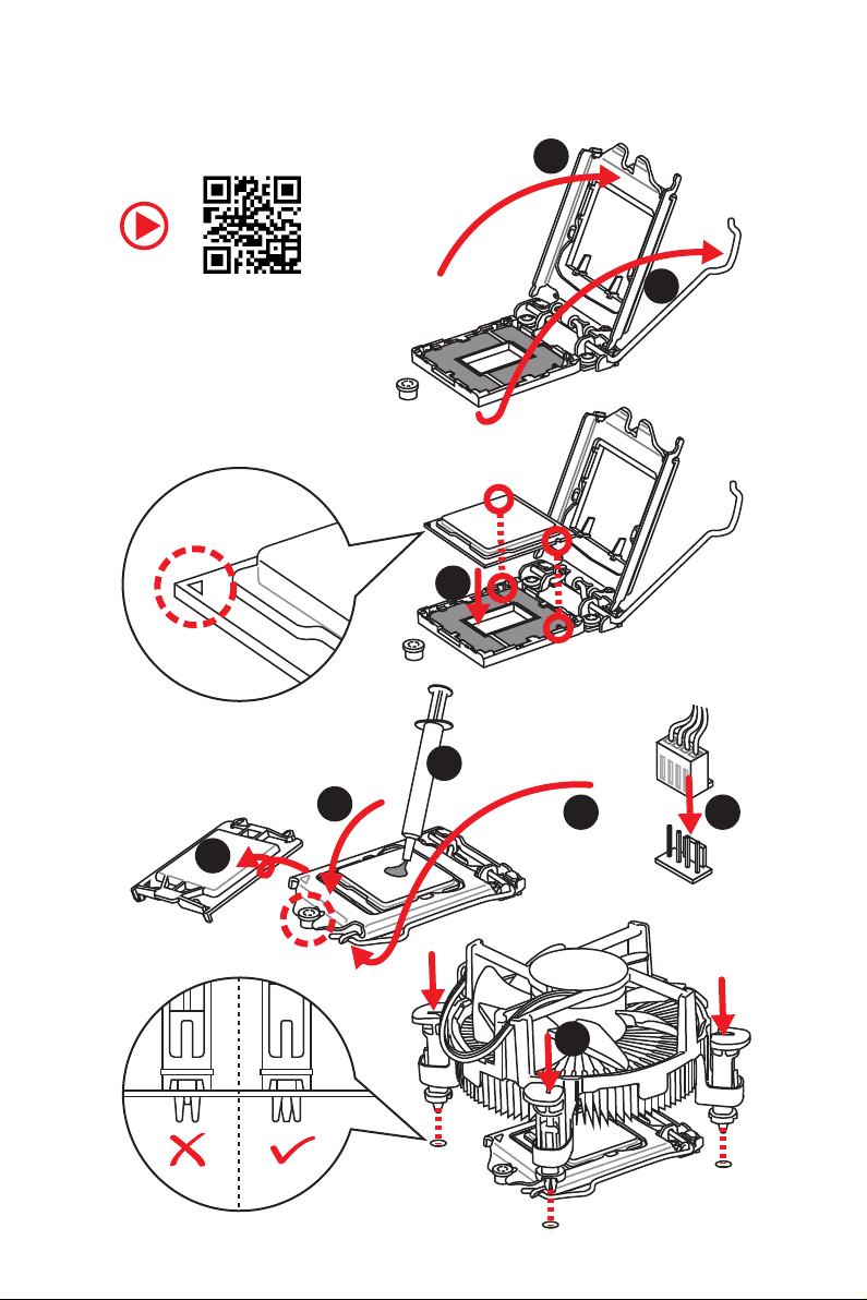
Installing a Processor/ Installation des Prozessors/ Installer un
processeur/ Установка процессора
2
http://youtu.be/bf5La099urI
6
1
3
7
4
5
9
Quick Start
II
8
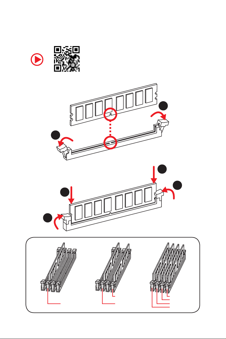
Installing DDR4 memory/ Installation des DDR4-Speichers/
Installer une mémoire DDR4/ Установка памяти DDR4
1
1
2
3
2
3
DIMMB2 DIMMB2
DIMMA2 DIMMA2 DIMMA2
DIMMB1
DIMMA1
Quick Start
III
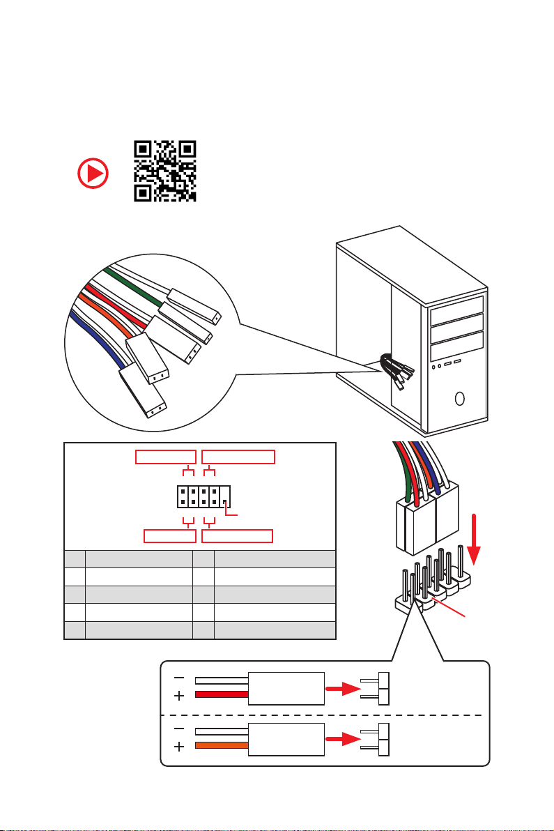
Connecting the Front Panel Header/ Anschließen der
RESET SW
POWER SW
POWER LED+
POWER LED-
HDD LED
Frontpanel-Stiftleiste/ Connecter un connecteur du panneau
avant/ Подключение разъемов передней панели
Power LED
JFP1
Power Switch
+++—
——
2 10
1
—
+
HDD LED Reset Switch
1 HDD LED + 2 Power LED +
3 HDD LED — 4 Power LED —
5 Reset Switch 6 Power Switch
7 Reset Switch 8 Power Switch
9 Reserved 10 No Pin
Quick Start
IV
9
Reserved
HDD LED
POWER LED
RESET SW
HDD LED
JFP1
HDD LED HDD LED +
POWER LED POWER LED +
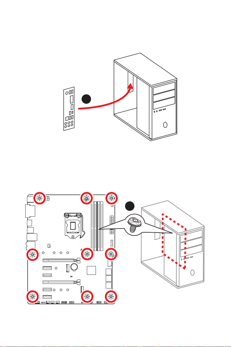
Installing the Motherboard/ Installation des Motherboards/
Installer la carte mère/ Установка материнской платы
1
2
BAT1
Quick Start
V
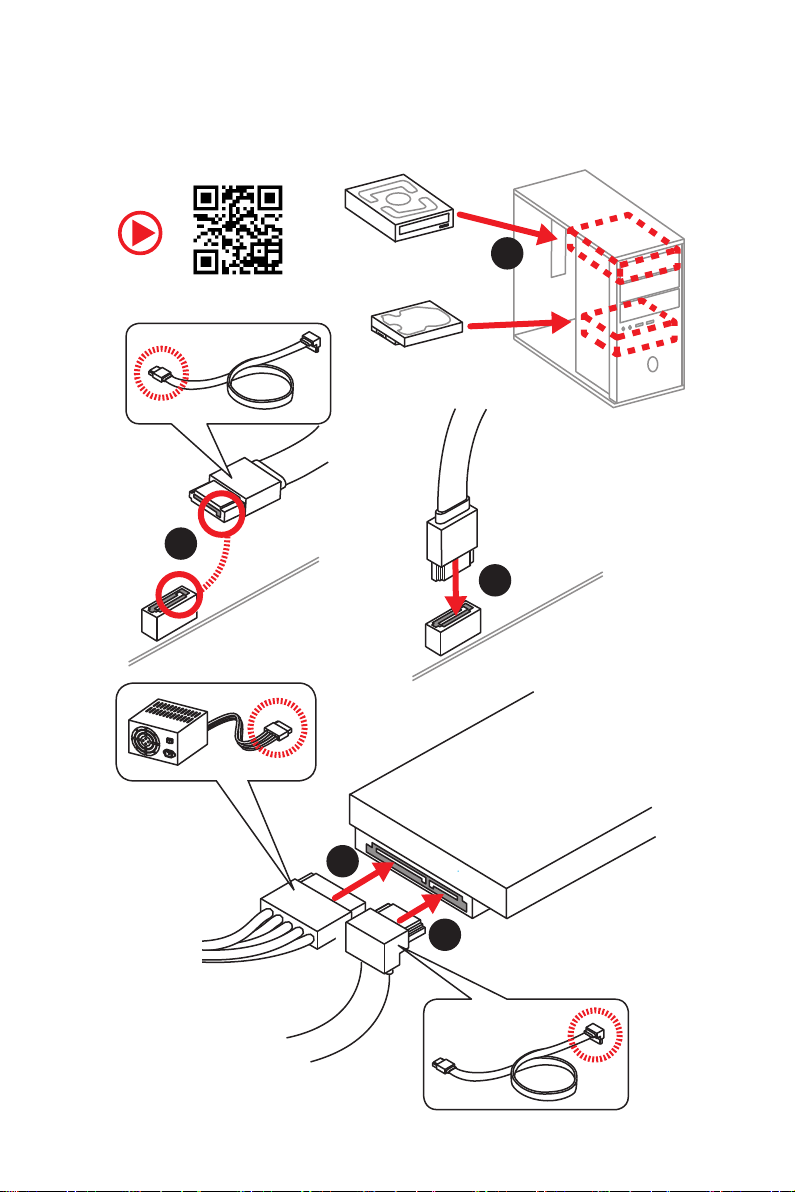
Installing SATA Drives/ Installation der SATA-Laufwerke/
Installer le disque dur SATA/ Установка дисков SATA
1
2
3
VI
5
4
Quick Start
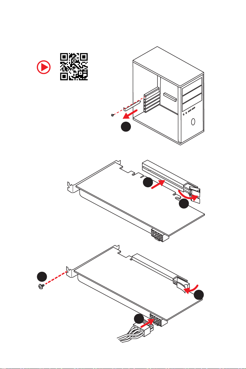
Installing a Graphics Card/ Einbau der Grafikkarte/ Installer
une carte graphique/ Установка дискретной видеокарты
1
3
2
5
4
6
Quick Start
VII
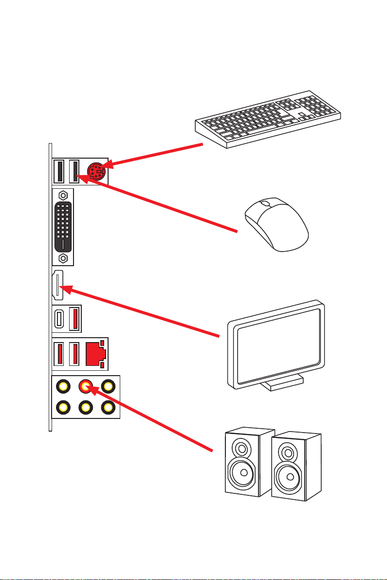
Connecting Peripheral Devices/ Peripheriegeräte/
Connecter un périphérique anschliessen/ Подключение
периферийных устройств
VIII
Quick Start
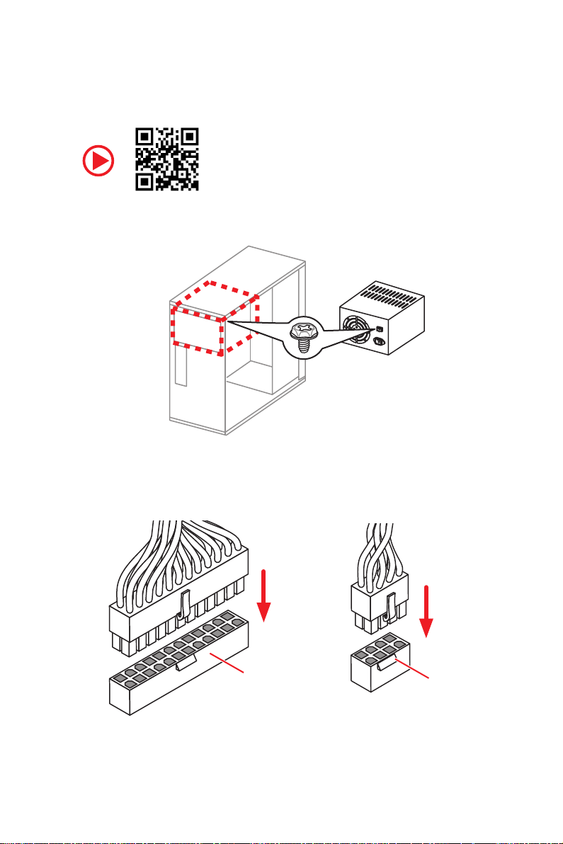
Connecting the Power Connectors/ Stromanschlüsse
anschliessen/ Connecter les câbles du module d’alimentation/
Подключение разъемов питания
ATX_PWR1
CPU_PWR1
Quick Start
IX
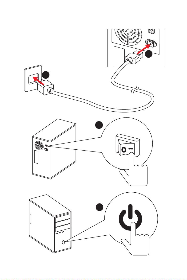
Power On/ Einschalten/ Mettre sous-tension/ Включение
питания
1
2
3
Quick Start
X
4

Contents
Safety Information ……………………………………………………………………………………. 2
Specifications …………………………………………………………………………………………… 3
Package contents …………………………………………………………………………………….. 7
Rear I/O Panel …………………………………………………………………………………………. 8
LAN Port LED Status Table…………………………………………………………………………. 8
Audio Ports Configuration ………………………………………………………………………….. 8
Realtek Audio Console ………………………………………………………………………………. 9
Overview of Components ………………………………………………………………………… 11
CPU Socket …………………………………………………………………………………………….. 12
DIMM Slots ……………………………………………………………………………………………… 13
PCI_E1~6: PCIe Expansion Slots ……………………………………………………………….. 14
SATA1~6: SATA 6Gb/s Connectors …………………………………………………………….. 14
M2_1~2: M.2 Slots (Key M) ……………………………………………………………………….. 15
JFP1, JFP2: Front Panel Connectors …………………………………………………………. 16
JCOM1: Serial Port Connector ………………………………………………………………….. 16
CPU_PWR1, ATX_PWR1: Power Connectors ………………………………………………. 17
JUSB1~2: USB 2.0 Connectors ………………………………………………………………….. 18
JUSB3~4: USB 3.1 Gen1 Connectors …………………………………………………………. 18
CPU_FAN1, PUMP_FAN1, SYS_FAN1~5: Fan Connectors …………………………….. 19
JAUD1: Front Audio Connector ………………………………………………………………….20
JCI1: Chassis Intrusion Connector …………………………………………………………….. 20
JTPM1: TPM Module Connector ………………………………………………………………… 21
JBAT1: Clear CMOS (Reset BIOS) Jumper ………………………………………………….. 21
JRGB1, JRGB2: RGB LED connectors ………………………………………………………… 22
EZ Debug LED …………………………………………………………………………………………. 22
Installing OS, Drivers & Utilities ………………………………………………………………. 23
Installing Windows® 10 …………………………………………………………………………….. 23
Installing Drivers …………………………………………………………………………………….. 23
Installing Utilities ……………………………………………………………………………………. 23
BIOS Setup …………………………………………………………………………………………….. 24
Entering BIOS Setup ………………………………………………………………………………… 24
Resetting BIOS ………………………………………………………………………………………… 25
Updating BIOS …………………………………………………………………………………………. 25
EZ Mode …………………………………………………………………………………………………. 26
Advanced Mode ………………………………………………………………………………………. 28
OC Menu…………………………………………………………………………………………………. 29
Contents
1

Safety Information
y The components included in this package are prone to damage from electrostatic
discharge (ESD). Please adhere to the following instructions to ensure successful
computer assembly.
y Ensure that all components are securely connected. Loose connections may cause
the computer to not recognize a component or fail to start.
y Hold the motherboard by the edges to avoid touching sensitive components.
y It is recommended to wear an electrostatic discharge (ESD) wrist strap when
handling the motherboard to prevent electrostatic damage. If an ESD wrist strap is
not available, discharge yourself of static electricity by touching another metal object
before handling the motherboard.
y Store the motherboard in an electrostatic shielding container or on an anti-static pad
whenever the motherboard is not installed.
y Before turning on the computer, ensure that there are no loose screws or metal
components on the motherboard or anywhere within the computer case.
y Do not boot the computer before installation is completed. This could cause
permanent damage to the components as well as injury to the user.
y If you need help during any installation step, please consult a certified computer
technician.
y Always turn off the power supply and unplug the power cord from the power outlet
before installing or removing any computer component.
y Keep this user guide for future reference.
y Keep this motherboard away from humidity.
y Make sure that your electrical outlet provides the same voltage as is indicated on the
PSU, before connecting the PSU to the electrical outlet.
y Place the power cord such a way that people can not step on it. Do not place anything
over the power cord.
y All cautions and warnings on the motherboard should be noted.
y If any of the following situations arises, get the motherboard checked by service
personnel:
Liquid has penetrated into the computer.
The motherboard has been exposed to moisture.
The motherboard does not work well or you can not get it work according to user
guide.
The motherboard has been dropped and damaged.
The motherboard has obvious sign of breakage.
y Do not leave this motherboard in an environment above 60°C (140°F), it may damage
the motherboard.
Safety Information
2

Specifications
Supports Intel
CPU
Core™ / Pentium
socket
* Please go to www.intel.com for more compatibility information.
Chipset Intel® Z390 Chipset
y 4x DDR4 memory slots, support up to 64GB*
y Supports DDR4 4400(OC)/ 4300(OC)/ 4266(OC)/ 4200(OC)/
4133(OC)/ 4000(OC)/ 3866(OC)/ 3733(OC)/ 3600(OC)/
3466(OC)/ 3400(OC)/ 3333(OC)/ 3300(OC)/ 3200(OC)/ 3000(OC)
Memory
/ 2800(OC)/ 2666/ 2400/ 2133 MHz*
y Supports Dual-Channel mode
y Supports non-ECC, un-buffered memory
y Supports Intel
* Please refer www.msi.com for more information on compatible memory.
y 2x PCIe 3.0 x16 slots
Expansion Slot
y 4x PCIe 3.0 x1 slots
y 1 x M.2 slot with E key for Integrated Intel
(CNVi) module only
y 1x HDMI™ port, supports a maximum resolution of
Onboard Graphics
4096×2160@24Hz
y 1x DVI-D port, supports a maximum resolution of
1920×1200@60Hz
®
Core™ 9000 Series family/ 8th Gen Intel®
®
Gold / Celeron® processors for LGA 1151
®
Extreme Memory Profile (XMP)
®
Wireless-AC
Multi-GPU y Supports 2-Way AMD
®
Z390 Chipset
Intel
y 6x SATA 6Gb/s ports*
y 2x M.2 slots (Key M)*
M2_1 supports up to PCIe 3.0 x4 and SATA 6Gb/s, 2242/
2260/ 2280/ 22110 storage devices
Storage
M2_2 supports up to PCIe 3.0 x4 and SATA 6Gb/s, 2242/
2260/ 2280 storage devices
®
Intel
Optane™ Memory Ready**
* M.2 slots and SATA ports share the bandwidth. Please refer to page 15 for
details.
** Before using Intel
updated the drivers and BIOS to the latest version from MSI website.
®
Optane™ memory modules, please ensure that you have
Continued on next page
®
CrossFire™ Technology
Specifications
3

RAID
Continued from previous page
®
Z390 Chipset
Intel
y Supports RAID 0, RAID1, RAID 5 and RAID 10 for SATA
storage devices
y Supports RAID 0, RAID 1 for M.2 PCIe storage devices
LAN y 1x Intel
®
y Intel
2x USB 3.1 Gen2 (SuperSpeed USB 10Gbps) ports (1
Type-A port and 1 Type-C port) on the back panel
6x USB 3.1 Gen1 (SuperSpeed USB) ports (2 Type-A
USB
ports on the back panel, 4 ports available through the
internal USB 3.1 connectors)
6x USB 2.0 (High-speed USB) ports (2 Type-A ports on
the back panel, 4 ports available through the internal
USB 2.0 connectors)*
* The CNVI_1 and JUSB2 share the same bandwidth. Please refer to page 18 for
details.
Audio
y Realtek
7.1-Channel High Definition Audio
y 1x PS/2 keyboard/ mouse combo port
y 2x USB 2.0 Type-A ports
y 1x DVI-D port
y 1x HDMI port
Back Panel
Connectors
y 1x USB 3.1 Gen2 Type-A port
y 1x USB 3.1 Gen2 Type-C port
y 1x LAN (RJ45) port
y 2x USB 3.1 Gen1 Type-A ports
y 6x OFC audio jacks
®
I219-V Gigabit LAN controller
Z390 Chipset
®
ALC892 Codec
Specifications
4
Continued on next page
Continued from previous page
y 1x 24-pin ATX main power connector
y 1x 8-pin ATX 12V power connector
y 6x SATA 6Gb/s connectors
y 3x M.2 slots (2 M-Key slots,1 E-Key slot)
y 2x USB 3.1 Gen1 connectors (supports additional 4 USB 3.1
Gen1 ports)
y 2x USB 2.0 connectors (supports additional 4 USB 2.0
ports)
y 1x 4-pin CPU fan connector
Internal Connectors
I/O Controller NUVOTON NCT6797 Controller Chip
Hardware Monitor
y 1x 4-pin Water Pump connector
y 5x 4-pin system fan connectors
y 1x Front panel audio connector
y 2x System panel connectors
y 1x Chassis Intrusion connector
y 1x TPM module connector
y 2x 4-pin RGB LED connectors
y 1x Serial Port connector
y 1x Clear CMOS jumper
y CPU/System temperature detection
y CPU/System fan speed detection
y CPU/System fan speed control
Form Factor
BIOS Features
y ATX Form Factor
y 12 in. x 9.6 in. (30.5 cm x 24.4 cm)
y 1x 128 Mb flash
y UEFI AMI BIOS
y ACPI 6.1, SMBIOS 2.8
y Multi-language
Continued on next page
Specifications
5
Software
Dragon Center
Features
Special Features
Continued from previous page
y Drivers
y DRAGON CENTER
y MYSTIC LIGHT
y Open Broadcaster Software (OBS)
y CPU-Z MSI GAMING
®
y Intel
Extreme Tuning Utility
y Google Chrome™ ,Google Toolbar, Google Drive
y Norton™ Internet Security Solution
y GAME OPTIMIZATION
y OC Performance
y Hardware Monitor
y Eyerest
y LAN Manager
y Live Update
Please refer to http://download.msi.
com/manual/mb/DRAGONCENTER2.
pdf for more details.
y Audio
Audio Boost
y Network
GAMING LAN with GAMING LAN Manage
Intel CNVi Ready
y Storage
Twin Turbo M.2
y Cooling
Extended Heastink Design
Pump Fan
GAMING Fan Control
y LED
Mystic Light Extension (RGB)
Mystic Light Sync
EZ DEBUG LED
y Protection
PCI-E Steel Armor
PCI-E Steel Slot
Specifications
6
Continued on next page
Continued from previous page
y Performance
Multi GPU-CrossFire Technology
DDR4 Boost
Core Boost
GAME Boost
USB with type A+C
Intel Turbo USB 3.1 Gen2
Special Features
y VR
VR Ready
y Gamer Experience
GAMING HOTKEY
GAMING MOUSE Control
APP Player
y BIOS
Click BIOS 5
Package contents
Please check the contents of your motherboard package. It should contain:
Motherboard MPG Z390 GAMING PLUS
Cable SATA 6Gb/s Cables 2
M.2 Screw 2
Accessories
Application DVD Driver DVD 1
Documentation
I/O Shield 1
Case Badge 1
VIP Card 1
User Manual 1
Quick Installation Guide 1
Important
If any of the above items are damaged or missing, please contact your retailer.
Package contents
7
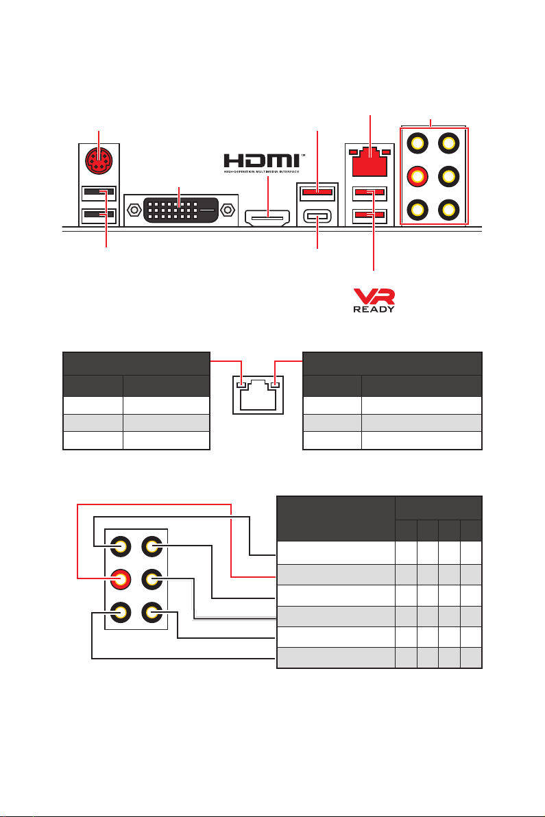
Rear I/O Panel
PS/2
DVI-D
USB 2.0
LAN Port LED Status Table
Link/ Activity LED
Status Description
Off No link
Yellow Linked
Blinking Data activity
Audio Ports Configuration
USB 3.1 Gen2
USB 3.1 Gen2 Type-C
USB 3.1 Gen1
Speed LED
Status Description
Off 10 Mbps connection
Green 100 Mbps connection
Orange 1 Gbps connection
LAN
Audio Ports
Rear I/O Panel
8
Audio Ports
Line-In
Line-Out/ Front Speaker Out ● ● ● ●
Rear Speaker Out ● ● ●
Center/ Subwoofer Out ● ●
Side Speaker Out ●
Mic In
Channel
2 4 6 8
(●: connected, Blank: empty)
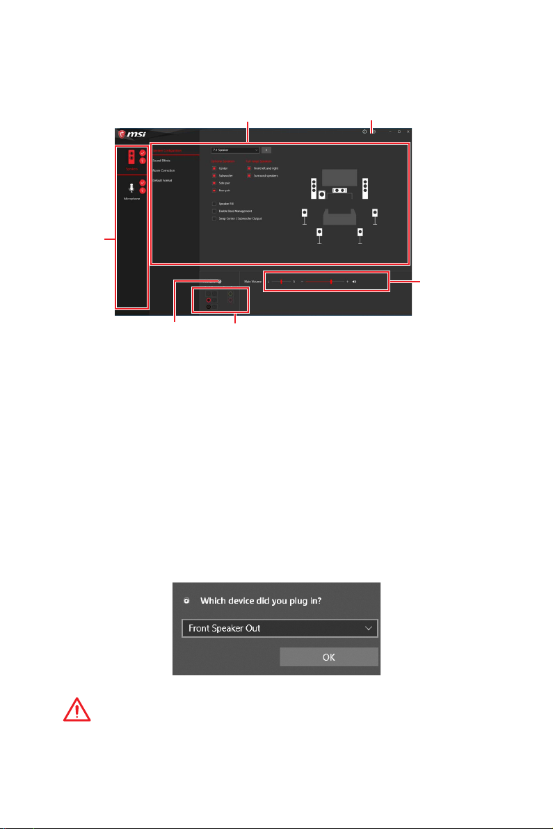
Realtek Audio Console
After Realtek Audio Console is installed. You can use it to change sound settings to get
better sound experience.
Device
Selection
Application Enhancement Advanced Settings
Main Volume
Connector Settings
Jack Status
y Device Selection — allows you to select a audio output source to change the related
options. The check sign indicates the devices as default.
y Application Enhancement — the array of options will provide you a complete guidance
of anticipated sound effect for both output and input device.
y Main Volume — controls the volume or balance the right/left side of the speakers that
you plugged in front or rear panel by adjust the bar.
y Advanced Settings — provides the mechanism to deal with 2 independent audio
streams.
y Jack Status — depicts all render and capture devices currently connected with your
computer.
y Connector Settings — configures the connection settings.
Auto popup dialog
When you plug into a device at an audio jack, a dialogue window will pop up asking you
which device is current connected.
Each jack corresponds to its default setting as shown on the next page.
Important
The pictures above for reference only and may vary from the product you purchased.
Rear I/O Panel
9
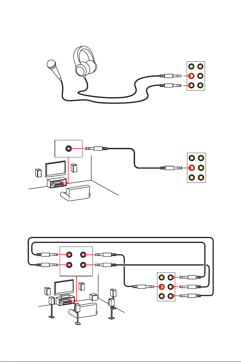
Audio jacks to headphone and microphone diagram
Audio jacks to stereo speakers diagram
AUDIO INPUT
Audio jacks to 7.1-channel speakers diagram
AUDIO INPUT
Rear Front
Side Center/
Subwoofer
Rear I/O Panel
10
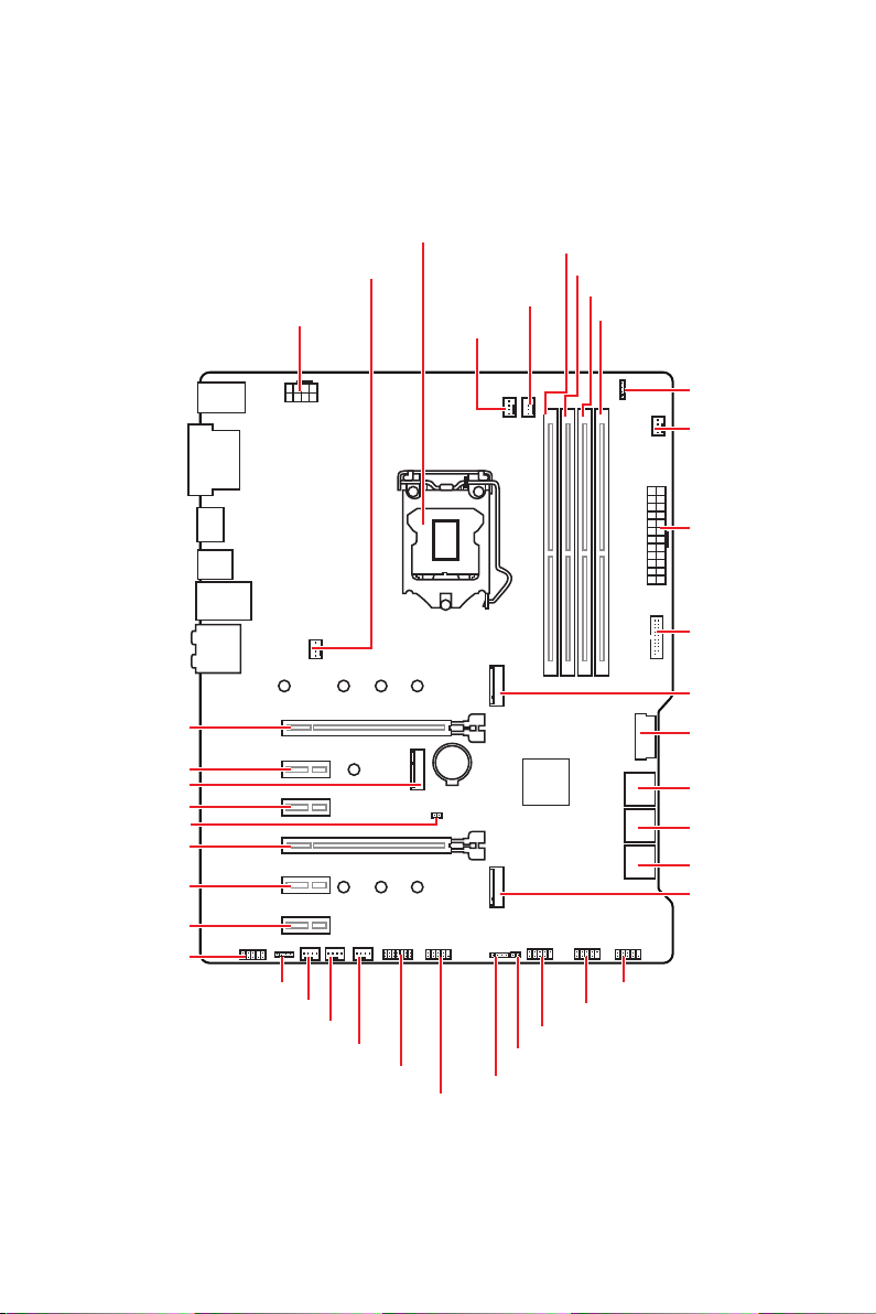
Overview of Components
PCI_E1
PCI_E2
CNVI_1
PCI_E3
JBAT1
PCI_E4
PCI_E5
PCI_E6
JAUD1
CPU_PWR1
JRGB1
SYS_FAN2
SYS_FAN3
SYS_FAN1
SYS_FAN4
CPU Socket
JTPM1
JCOM1
CPU_FAN1
PUMP_FAN1
BAT1
JFP2
DIMMA1
DIMMA2
DIMMB1
DIMMB2
JRGB2
SYS_FAN5
ATX_PWR1
JUSB4
M2_1
JUSB3
SATA▼1▲2
SATA▼3▲4
SATA▼5▲6
M2_2
JFP1
JUSB2
JUSB1
JCI1
Overview of Components
11
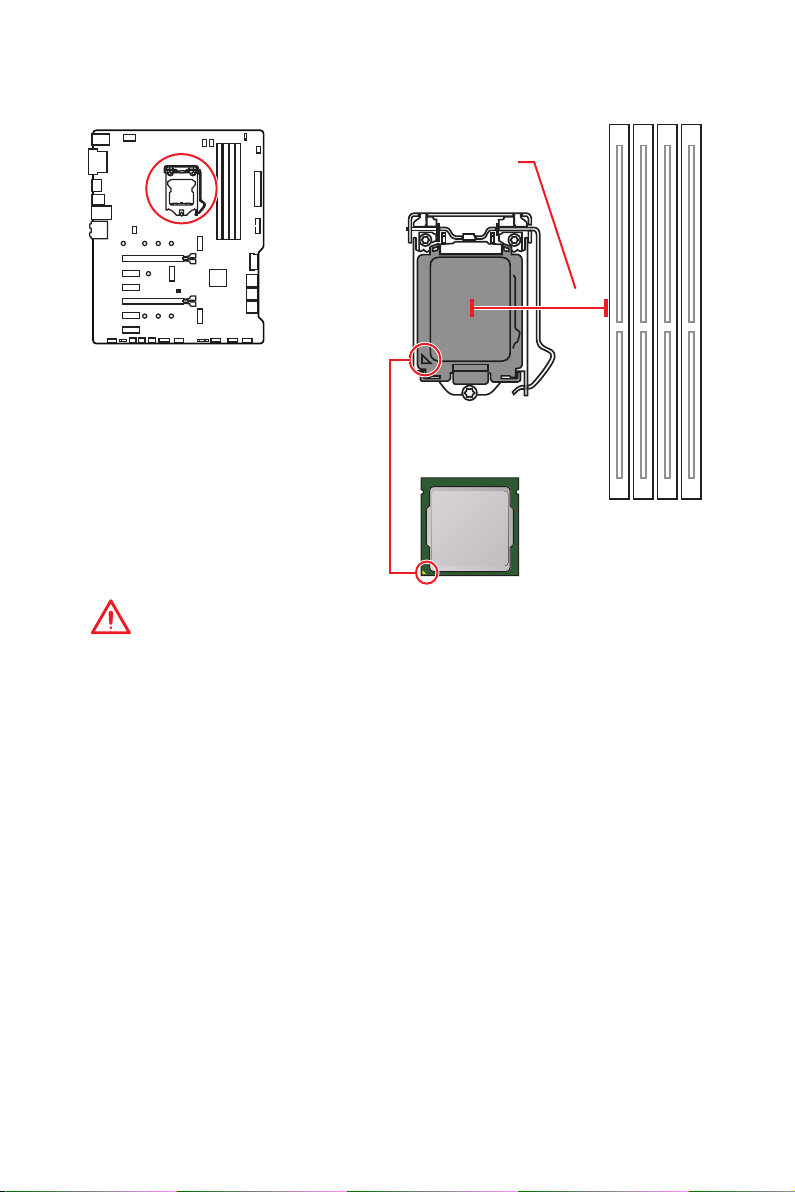
CPU Socket
Distance from the center of the
CPU to the nearest DIMM slot.
50.7 mm
Introduction to the LGA 1151 CPU
The surface of the LGA 1151 CPU has
two notches and a golden triangle to
assist in correctly lining up the CPU for
motherboard placement. The golden
triangle is the Pin 1 indicator.
Important
y
Always unplug the power cord from the power outlet before installing or removing
the CPU.
y
Please retain the CPU protective cap after installing the processor. MSI will deal with
Return Merchandise Authorization (RMA) requests if only the motherboard comes with
the protective cap on the CPU socket.
y
When installing a CPU, always remember to install a CPU heatsink. A CPU heatsink
is necessary to prevent overheating and maintain system stability.
y
Confirm that the CPU heatsink has formed a tight seal with the CPU before booting
your system.
y
Overheating can seriously damage the CPU and motherboard. Always make sure
the cooling fans work properly to protect the CPU from overheating. Be sure to apply
an even layer of thermal paste (or thermal tape) between the CPU and the heatsink to
enhance heat dissipation.
y
Whenever the CPU is not installed, always protect the CPU socket pins by covering
the socket with the plastic cap.
y
If you purchased a separate CPU and heatsink/ cooler, Please refer to the
documentation in the heatsink/ cooler package for more details about installation.
y
This motherboard is designed to support overclocking. Before attempting to
overclock, please make sure that all other system components can tolerate
overclocking. Any attempt to operate beyond product specifications is not
recommended. MSI
operation beyond product specifications.
®
does not guarantee the damages or risks caused by inadequate
Overview of Components
12
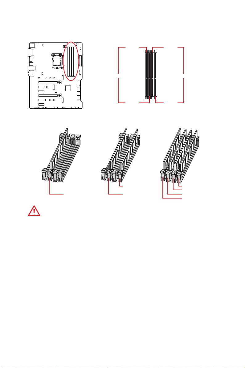
DIMM Slots
DIMMA1 DIMMB1
Channel A Channel B
DIMMA2 DIMMB2
Memory module installation recommendation
DIMMB2 DIMMB2
DIMMA2 DIMMA2 DIMMA2
DIMMB1
DIMMA1
Important
y
Always insert memory modules in the DIMMA2 slot first.
y
Due to chipset resource usage, the available capacity of memory will be a little less
than the amount of installed.
y
Based on CPU specification, the Memory DIMM voltage below 1.35V is suggested to
protect the CPU.
y
Please note that the maximum capacity of addressable memory is 4GB or less
for 32-bit Windows OS due to the memory address limitation. Therefore, we
recommended that you to install 64-bit Windows OS if you want to install more than
4GB memory on the motherboard.
y
Some memory may operate at a lower frequency than the marked value when
overclocking due to the memory frequency operates dependent on its Serial Presence
Detect (SPD). Go to BIOS and find the Memory Try It! to set the memory frequency if
you want to operate the memory at the marked or at a higher frequency.
y
It is recommended to use a more efficient memory cooling system for full DIMMs
installation or overclocking.
y
The stability and compatibility of installed memory module depend on installed CPU
and devices when overclocking.
Overview of Components
13
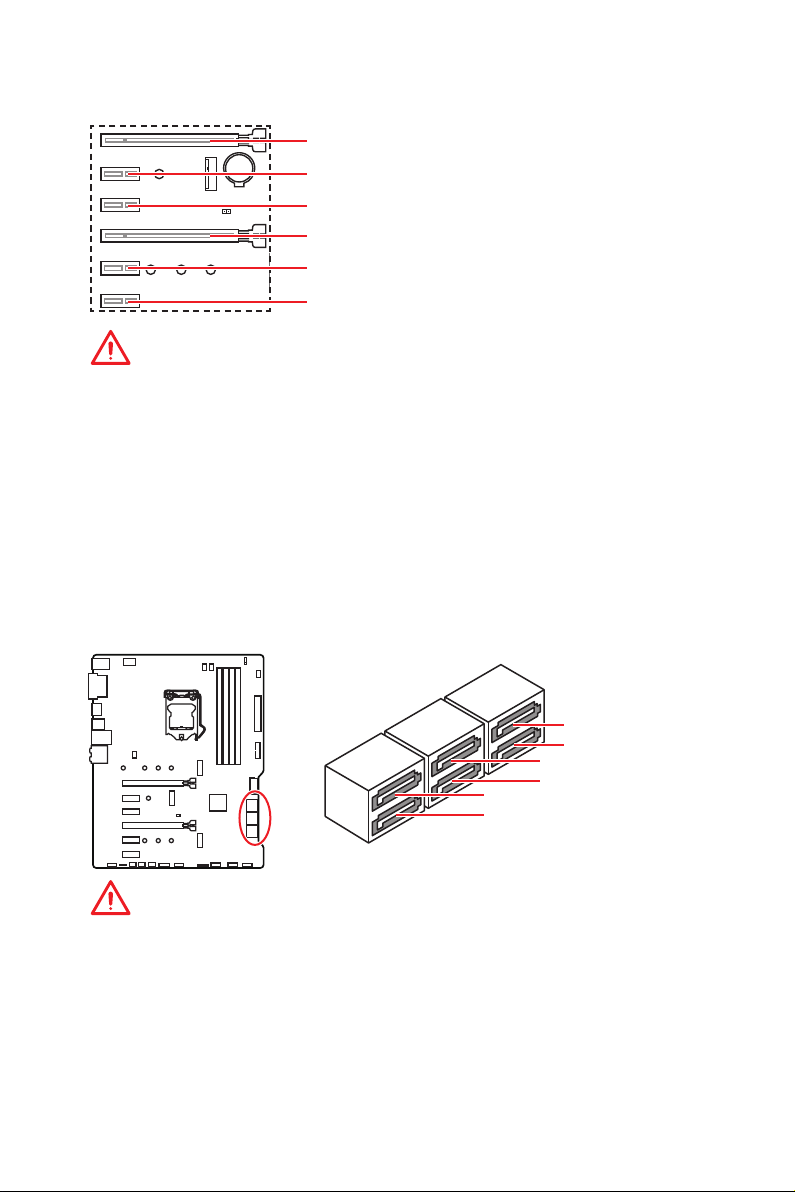
PCI_E1~6: PCIe Expansion Slots
PCI_E1: PCIe 3.0 x16 (CPU lanes)
BAT1
PCI_E2: PCIe 3.0 x1 (PCH lanes)
PCI_E3: PCIe 3.0 x1 (PCH lanes)
PCI_E4: PCIe 3.0 x4 (PCH lanes)
PCI_E5: PCIe 3.0 x1 (PCH lanes)
PCI_E6: PCIe 3.0 x1 (PCH lanes)
Important
y
If you install a large and heavy graphics card, you need to use a tool such as MSI
Gaming Series Graphics Card Bolster to support its weight and to prevent deformation
of the slot.
y
For a single PCIe x16 expansion card installation with optimum performance, using
the PCI_E1 slot is recommended.
y
When adding or removing expansion cards, always turn off the power supply and
unplug the power supply power cable from the power outlet. Read the expansion
card’s documentation to check for any necessary additional hardware or software
changes.
SATA1~6: SATA 6Gb/s Connectors
These connectors are SATA 6Gb/s interface ports. Each connector can connect to one
SATA device.
SATA2
SATA1
SATA4
SATA3
SATA6
SATA5
Important
y
Please do not fold the SATA cable at a 90-degree angle. Data loss may result during
transmission otherwise.
y
SATA cables have identical plugs on either sides of the cable. However, it is
recommended that the flat connector be connected to the motherboard for space
saving purposes.
y
The SATA2 will be unavailable when installing M.2 SATA device into M2_1 slot.
y
The SATA5 & SATA6 will be unavailable when installing M.2 PCIe/ SATA device into
M2_2 slot.
Overview of Components
14
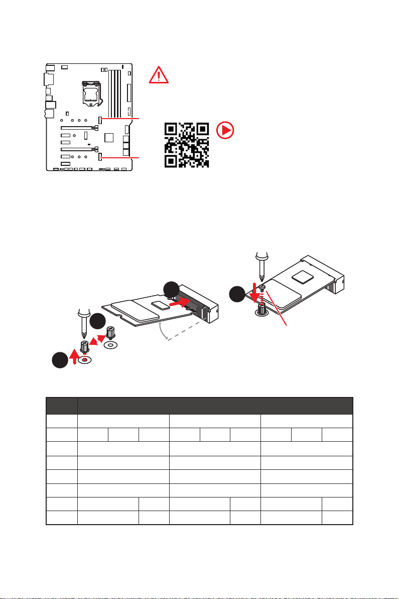
M2_1~2: M.2 Slots (Key M)
Important
y
Intel® RST only supports PCIe M.2 SSD with UEFI ROM.
y
Intel® Optane™ Memory Ready.
M2_1
M2_2
Installing M.2 device
1. Loosen the M.2 riser screw from the
motherboard.
2. Move and fasten the M.2 riser screw to
the appropriate location for your M.2
SSD.
3. Insert your M.2 SSD into the M.2 slot at a
30-degree angle.
Video Demonstration
Watch the video to learn how to Install
M.2 module.
4. Secure the M.2 SSD in place with
the supplied M.2 screw.
3
4
2
30°
Supplied M.2 screw
1
M.2 and SATA combination table
Slot Available SATA/ M.2 Connectors
M2_1 PCIe SATA Empty
M2_2 PCIe SATA Empty PCIe SATA Empty PCIe S ATA Empty
SATA1 ✓ ✓ ✓
SATA2 ✓ ─ ✓
SATA3 ✓ ✓ ✓
SATA4 ✓ ✓ ✓
SATA5 ─ ✓ ─ ✓ ─ ✓
SATA6 ─ ✓ ─ ✓ ─ ✓
(SATA: M.2 SATA SSD, PCIe: M.2 PCIe SSD, ✓: available, ─: unavailable)
Overview of Components
15
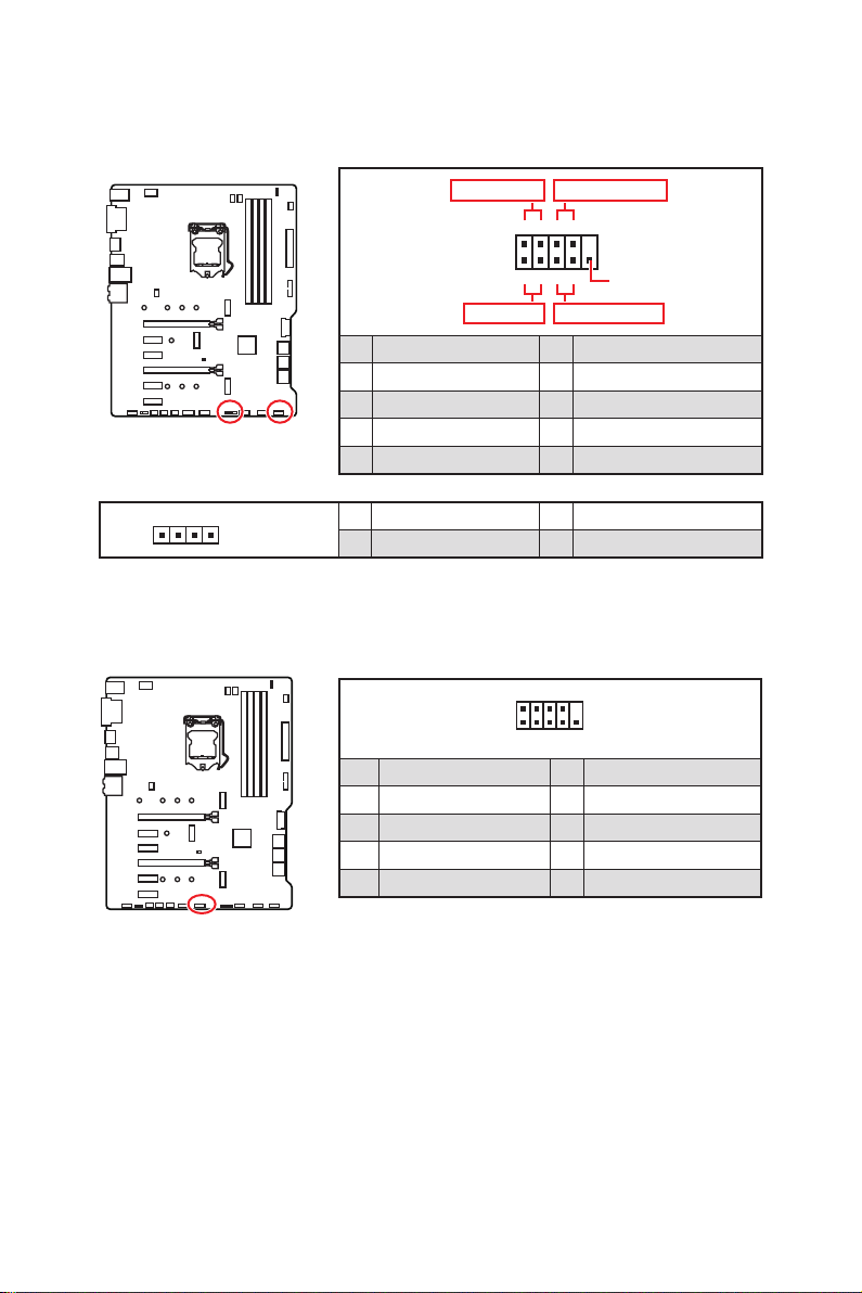
JFP1, JFP2: Front Panel Connectors
These connectors connect to the switches and LEDs on the front panel.
Power LED
JFP1
Power Switch
+++—
——
2 10
1
—
+
9
Reserved
HDD LED Reset Switch
1 HDD LED + 2 Power LED +
3 HDD LED — 4 Power LED —
5 Reset Switch 6 Power Switch
7 Reset Switch 8 Power Switch
9 Reserved 10 No Pin
1
JFP2
1 Speaker — 2 Buzzer +
3 Buzzer — 4 Speaker +
JCOM1: Serial Port Connector
This connector allows you to connect the optional serial port with bracket.
2 10
1
9
1 DCD 2 SIN
3 SOUT 4 DTR
5 Ground 6 DSR
7 RTS 8 CTS
9 RI 10 No Pin
Overview of Components
16
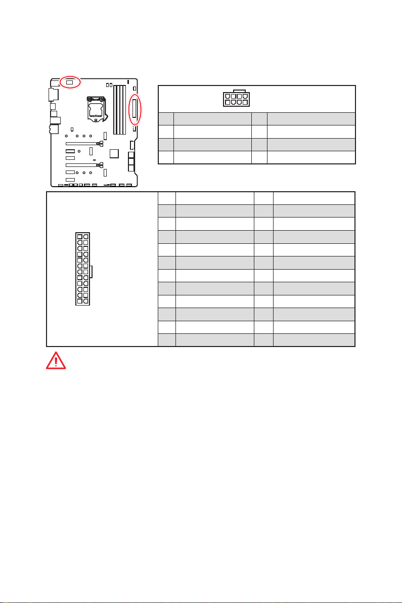
CPU_PWR1, ATX_PWR1: Power Connectors
These connectors allow you to connect an ATX power supply.
8
4 1
1 Ground 5 +12V
2 Ground 6 +12V
3 Ground 7 +12V
4 Ground 8 +12V
1 +3.3V 13 +3.3V
2 +3.3V 14 -12V
3 Ground 15 Ground
24
12
ATX_PWR1
131
4 +5V 16 PS-ON#
5 Ground 17 Ground
6 +5V 18 Ground
7 Ground 19 Ground
8 PWR OK 20 Res
9 5VSB 21 +5V
10 +12V 22 +5V
11 +12V 23 +5V
12 +3.3V 24 Ground
5
CPU_PWR1
Important
Make sure that all the power cables are securely connected to a proper ATX power
supply to ensure stable operation of the motherboard.
Overview of Components
17
JUSB1~2: USB 2.0 Connectors
2 10
1
1 VCC 2 VCC
3 USB0- 4 USB1-
5 USB0+ 6 USB1+
7 Ground 8 Ground
9 No Pin 10 NC
Note : For JUSB2, the set of pins is unavailable when a Intel wireless-AC
(CNVi) module is installed in the CNVI_1 slot.
Note
9
Important
y
Note that the VCC and Ground pins must be connected correctly to avoid possible
damage.
y
In order to recharge your iPad,iPhone and iPod through USB ports, please install MSI
DRAGON CENTER utility.
y
The CNVI_1 and JUSB2 share the same bandwidth. And one USB port connecting to
JUSB2 is unavailable when the CNVI_1 slot has been installed.
JUSB3~4: USB 3.1 Gen1 Connectors
These connectors allow you to connect USB 3.1 Gen1 ports on the front panel.
10 11
1
20
1 Power 11 USB2.0+
2 USB3_RX_DN 12 USB2.0-
3 USB3_RX_DP 13 Ground
4 Ground 14 USB3_TX_C_DP
5 USB3_TX_C_DN 15 USB3_TX_C_DN
6 USB3_TX_C_DP 16 Ground
7 Ground 17 USB3_RX_DP
8 USB2.0- 18 USB3_RX_DN
9 USB2.0+ 19 Power
10 GND 20 No Pin
Important
Note that the Power and Ground pins must be connected correctly to avoid possible
damage.
Overview of Components
18
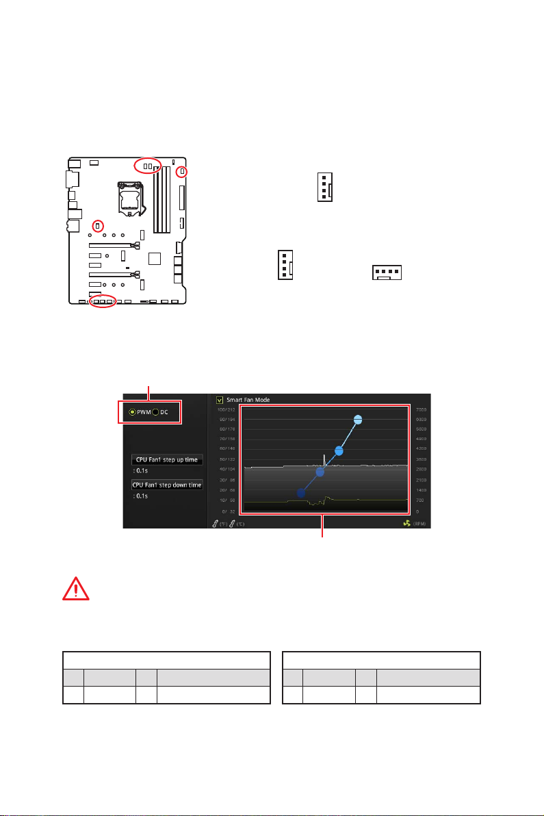
CPU_FAN1, PUMP_FAN1, SYS_FAN1~5: Fan Connectors
Fan connectors can be classified as PWM (Pulse Width Modulation) Mode or DC Mode.
PWM Mode fan connectors provide constant 12V output and adjust fan speed with
speed control signal. DC Mode fan connectors control fan speed by changing voltage.
You can follow the instruction below to adjust the fan connector to PWM or DC Mode.
Default PWM Mode fan connectors
1
CPU_FAN1/ PUMP_FAN1
Default DC Mode fan connectors
1
1
SYS_FAN1 & 5 SYS_FAN2, 3, 4
Switching fan mode and adjusting fan speed
You can switch between PWM mode and DC mode and adjust fan speed in BIOS >
HARDWARE MONITOR.
Select PWM mode or DC mode
There are gradient points of the fan speed that allow you to adjust
fan speed in relation to CPU temperature.
Important
Make sure fans are working properly after switching the PWM/ DC mode.
Pin definition of fan connectors
PWM Mode pin definition
1 Ground 2 +12V
3 Sense 4 Speed Control Signal
1 Ground 2 Voltage Control
3 Sense 4 NC
DC Mode pin definition
Overview of Components
19
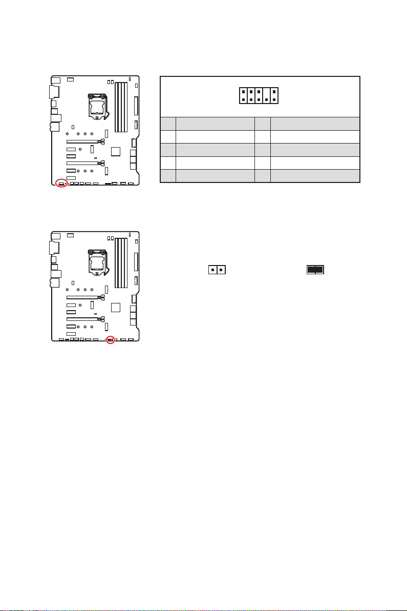
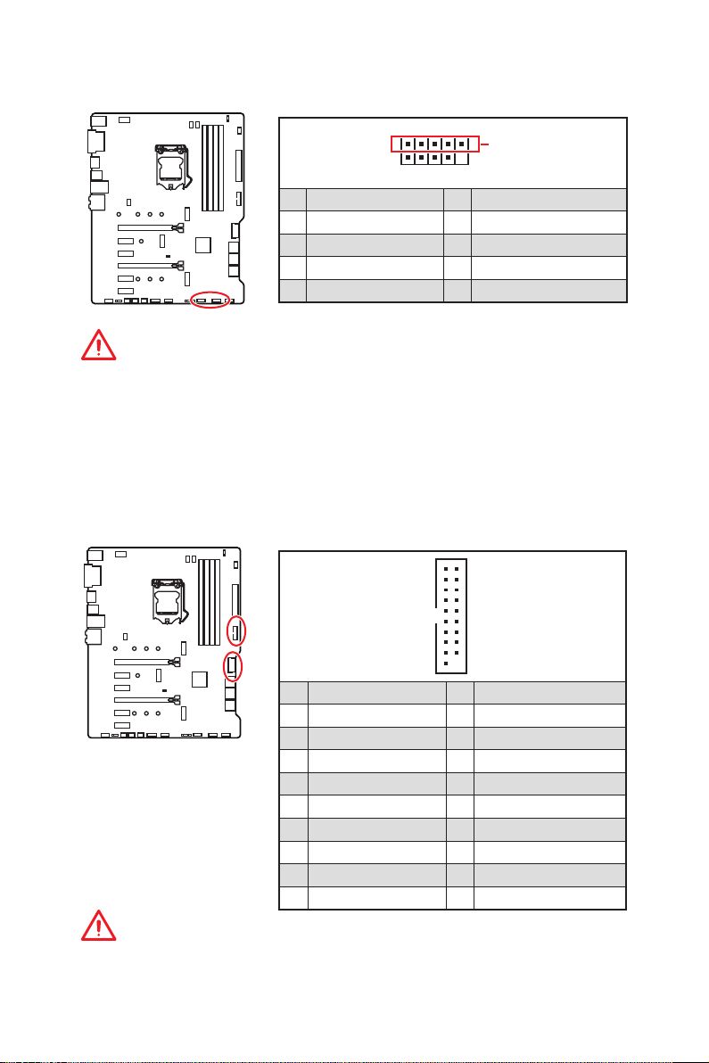
JAUD1: Front Audio Connector
This connector allows you to connect audio jacks on the front panel.
2 10
1
9
1 MIC L 2 Ground
3 MIC R 4 NC
5 Head Phone R 6 MIC Detection
7 SENSE_SEND 8 No Pin
9 Head Phone L 10 Head Phone Detection
JCI1: Chassis Intrusion Connector
This connector allows you to connect the chassis intrusion switch cable.
Normal
(default)
Trigger the chassis
intrusion event
Using chassis intrusion detector
1. Connect the JCI1 connector to the chassis intrusion switch/ sensor on the chassis.
2. Close the chassis cover.
3. Go to BIOS > SETTINGS > Security > Chassis Intrusion Configuration.
4. Set Chassis Intrusion to Enabled.
5. Press F10 to save and exit and then press the Enter key to select Yes .
6. Once the chassis cover is opened again, a warning message will be displayed on
screen when the computer is turned on.
Resetting the chassis intrusion warning
1. Go to BIOS > SETTINGS > Security > Chassis Intrusion Configuration.
2. Set Chassis Intrusion to Reset.
3. Press F10 to save and exit and then press the Enter key to select Yes .
Overview of Components
20
Loading…
I
Quick Start
Quick Start
Thank you for purchasing the MSI
®
MPG Z390 GAMING PLUS
motherboard. This Quick Start section provides demonstration
diagrams about how to install your computer. Some of the
installations also provide video demonstrations. Please link to the
URL to watch it with the web browser on your phone or tablet. You
may have even link to the URL by scanning the QR code.
Kurzanleitung
Danke, dass Sie das MSI
®
MPG Z390 GAMING PLUS Motherboard
gewählt haben. Dieser Abschnitt der Kurzanleitung bietet eine Demo
zur Installation Ihres Computers. Manche Installationen bieten
auch die Videodemonstrationen. Klicken Sie auf die URL, um diese
Videoanleitung mit Ihrem Browser auf Ihrem Handy oder Table
anzusehen. Oder scannen Sie auch den QR Code mit Ihrem Handy,
um die URL zu öffnen.
Présentation rapide
Merci d’avoir choisi la carte mère MSI
®
MPG Z390 GAMING PLUS.
Ce manuel fournit une rapide présentation avec des illustrations
explicatives qui vous aideront à assembler votre ordinateur. Des
tutoriels vidéo sont disponibles pour certaines étapes. Cliquez sur
le lien fourni pour regarder la vidéo sur votre téléphone ou votre
tablette. Vous pouvez également accéder au lien en scannant le QR
code qui lui est associé.
Быстрый старт
Благодарим вас за покупку материнской платы MSI
®
MPG Z390
GAMING PLUS. В этом разделе представлена информация,
которая поможет вам при сборке комьютера. Для некоторых
этапов сборки имеются видеоинструкции. Для просмотра
видео, необходимо открыть соответствующую ссылку в
веб—браузере на вашем телефоне или планшете. Вы также
можете выполнить переход по ссылке, путем сканирования
QR-кода.
ManualsPro
MSI
msi MPG Z390 Gaming Plus Gaming Motherboard User Manual
- October 30, 2023
- MSI
Table of Contents
- Compatibility list
- Troubleshooting
- References
- Read User Manual Online (PDF format)
- Download This Manual (PDF format)
msi MPG Z390 Gaming Plus Gaming Motherboard User Manual

Motherboard specification
https://us.msi.com/Motherboard/MPG-Z390-GAMING-PLUS/Specification
Compatibility list
- CPU – https://us.msi.com/Motherboard/MPG-Z390-GAMINGPLUS/support#support-cpu
- Memory – https://us.msi.com/Motherboard/MPG-Z390-GAMINGPLUS/support#support-mem-3
Troubleshooting
No power: https://us.msi.com/support/technical_details/MB_Boot_No_Power
No display: https://us.msi.com/support/technical_details/MB_Boot_No_Display
User Manual
https://download.msi.com/archive/mnu_exe/mb/E7B51v1.2.pdf
References
- us.msi.com/Motherboard/MPG-Z390-GAMING-PLUS/Specification
- us.msi.com/Motherboard/MPG-Z390-GAMING-PLUS/support#support-cpu
- us.msi.com/Motherboard/MPG-Z390-GAMING-PLUS/support#support-mem-3
- MSI USA
Read User Manual Online (PDF format)
Read User Manual Online (PDF format) >>
Download This Manual (PDF format)
Download this manual >>
I
Quick Start
Quick Start
Thank you for purchasing the MSI
®
MPG Z390 GAMING PLUS
motherboard. This Quick Start section provides demonstration
diagrams about how to install your computer. Some of the
installations also provide video demonstrations. Please link to the
URL to watch it with the web browser on your phone or tablet. You
may have even link to the URL by scanning the QR code.
Kurzanleitung
Danke, dass Sie das MSI
®
MPG Z390 GAMING PLUS Motherboard
gewählt haben. Dieser Abschnitt der Kurzanleitung bietet eine Demo
zur Installation Ihres Computers. Manche Installationen bieten
auch die Videodemonstrationen. Klicken Sie auf die URL, um diese
Videoanleitung mit Ihrem Browser auf Ihrem Handy oder Table
anzusehen. Oder scannen Sie auch den QR Code mit Ihrem Handy,
um die URL zu öffnen.
Présentation rapide
Merci d’avoir choisi la carte mère MSI
®
MPG Z390 GAMING PLUS.
Ce manuel fournit une rapide présentation avec des illustrations
explicatives qui vous aideront à assembler votre ordinateur. Des
tutoriels vidéo sont disponibles pour certaines étapes. Cliquez sur
le lien fourni pour regarder la vidéo sur votre téléphone ou votre
tablette. Vous pouvez également accéder au lien en scannant le QR
code qui lui est associé.
Быстрый старт
Благодарим вас за покупку материнской платы MSI
®
MPG Z390
GAMING PLUS. В этом разделе представлена информация,
которая поможет вам при сборке комьютера. Для некоторых
этапов сборки имеются видеоинструкции. Для просмотра
видео, необходимо открыть соответствующую ссылку в
веб—браузере на вашем телефоне или планшете. Вы также
можете выполнить переход по ссылке, путем сканирования
QR-кода.