
1
Quick Start
Quick Start
Thank you for purchasing the MSI® MPG Z590 GAMING CARBON WIFI/ MPG Z590
GAMING FORCE motherboard. This Quick Start section provides demonstration
diagrams about how to install your computer. Some of the installations also provide
video demonstrations. Please link to the URL to watch it with the web browser on your
phone or tablet. You may have even link to the URL by scanning the QR code.
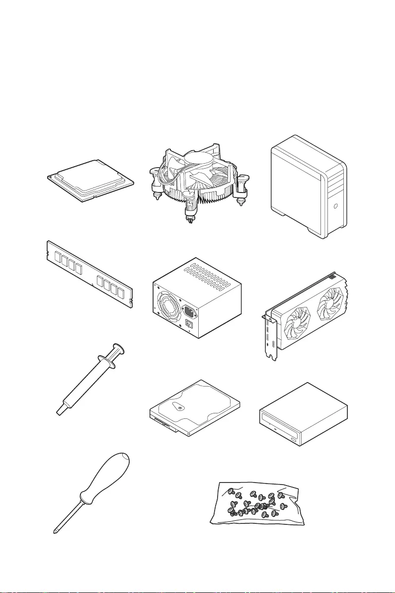
Preparing Tools and Components
Intel® LGA1200 CPU
CPU Fan
DDR4 Memory
Graphics Card
SATA Hard Disk Drive SATA DVD Drive
Phillips Screwdriver
Chassis
Power Supply Unit
A Package of Screws
Thermal Paste

2Quick Start
Safety Information
∙The components included in this package are prone to damage from electrostatic
discharge (ESD). Please adhere to the following instructions to ensure successful
computer assembly.
∙Ensure that all components are securely connected. Loose connections may cause
the computer to not recognize a component or fail to start.
∙Hold the motherboard by the edges to avoid touching sensitive components.
∙It is recommended to wear an electrostatic discharge (ESD) wrist strap when
handling the motherboard to prevent electrostatic damage. If an ESD wrist strap is
not available, discharge yourself of static electricity by touching another metal object
before handling the motherboard.
∙Store the motherboard in an electrostatic shielding container or on an anti-static
pad whenever the motherboard is not installed.
∙Before turning on the computer, ensure that there are no loose screws or metal
components on the motherboard or anywhere within the computer case.
∙Do not boot the computer before installation is completed. This could cause
permanent damage to the components as well as injury to the user.
∙If you need help during any installation step, please consult a certified computer
technician.
∙Always turn off the power supply and unplug the power cord from the power outlet
before installing or removing any computer component.
∙Keep this user guide for future reference.
∙Keep this motherboard away from humidity.
∙Make sure that your electrical outlet provides the same voltage as is indicated on
the PSU, before connecting the PSU to the electrical outlet.
∙Place the power cord such a way that people can not step on it. Do not place
anything over the power cord.
∙All cautions and warnings on the motherboard should be noted.
∙If any of the following situations arises, get the motherboard checked by service
personnel:
▪Liquid has penetrated into the computer.
▪The motherboard has been exposed to moisture.
▪The motherboard does not work well or you can not get it work according to user
guide.
▪The motherboard has been dropped and damaged.
▪The motherboard has obvious sign of breakage.
∙Do not leave this motherboard in an environment above 60°C (140°F), it may damage
the motherboard.
3
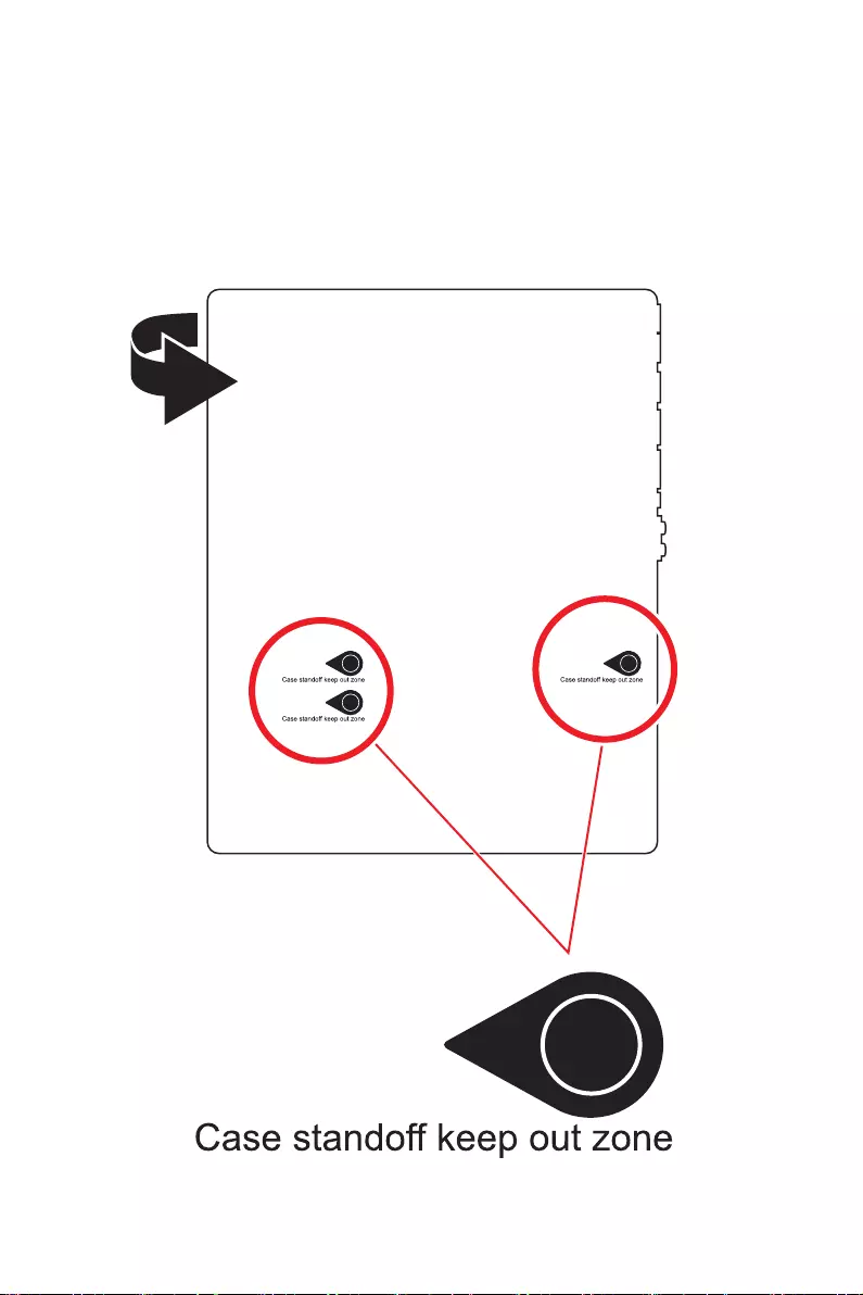
Quick Start
Case stand-off notification
Before installing the motherboard into the case, install first the necessary mounting
stand-off required for a motherboard on the mounting plate in the case.
To prevent damage to the motherboard, any unnecessary mounting stand-off between
the motherboard circuits and the computer case is prohibited. The Case standoff keep
out zone signs will be marked on the backside of motherboard (as shown below) to
serve as a warning to user.
4Quick Start
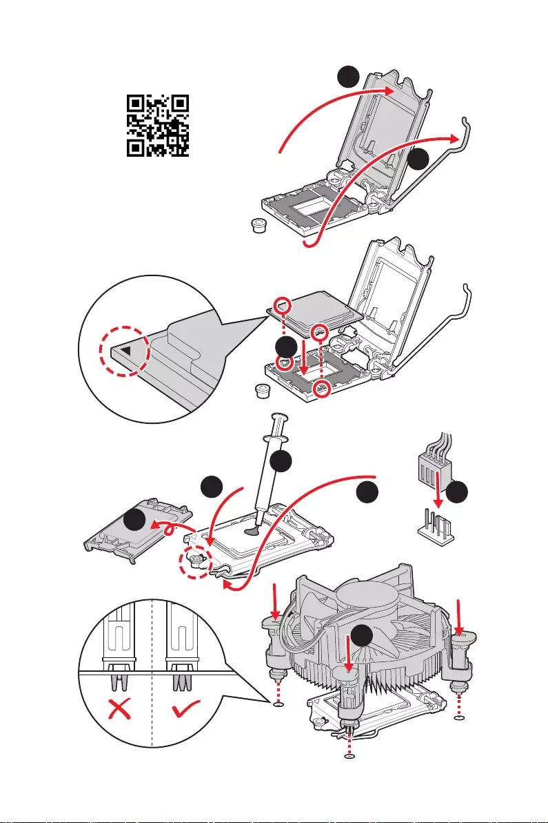
Installing a Processor
⚽
1
2
3
6
45
7
8
9
5
Quick Start
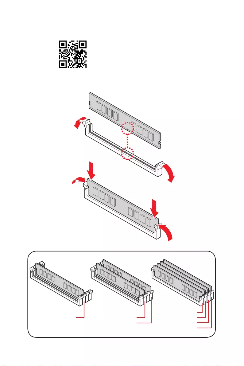
Installing DDR4 memory
⚽
DIMMA2 DIMMA2
DIMMB2
DIMMA1
DIMMA2
DIMMB1
DIMMB2
6Quick Start
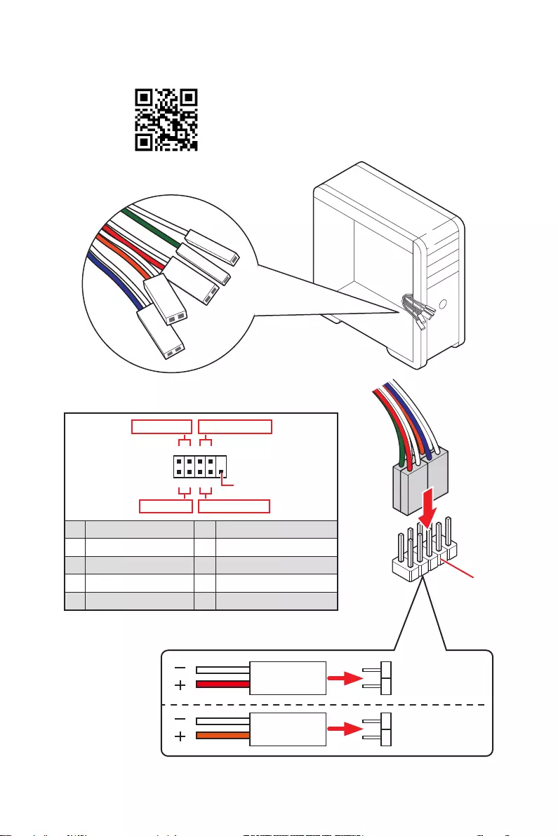
HDD LED
RESET SW
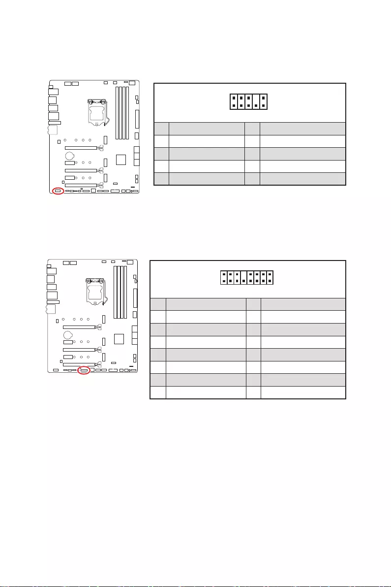
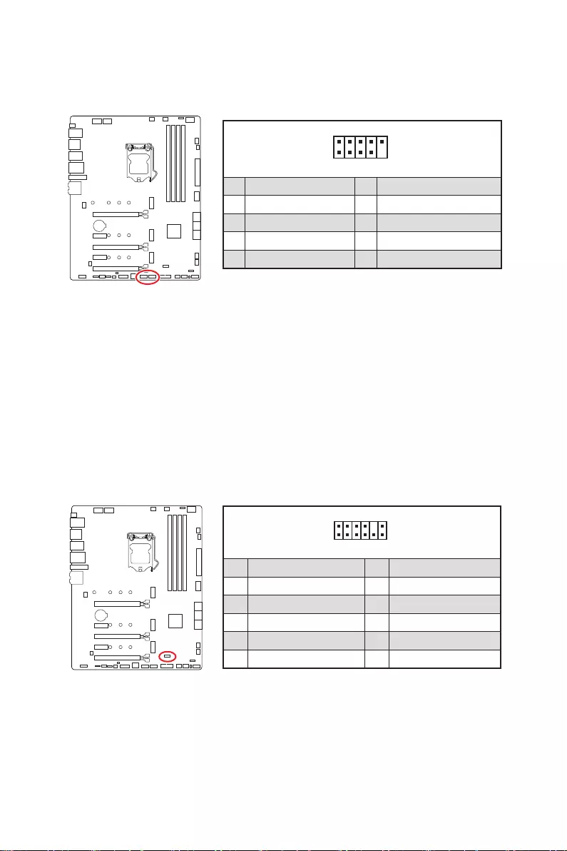
Connecting the Front Panel Header
JFP1
HDD LED HDD LED —
HDD LED +
POWER LED —
POWER LED +
POWER LED
1
2 10
9
+
+
+— ——
—
+
Power LED
HDD LED Reset Switch
Reserved
Power Switch
JFP1
1 HDD LED + 2 Power LED +
3 HDD LED — 4 Power LED —
5 Reset Switch 6 Power Switch
7 Reset Switch 8 Power Switch
9 Reserved 10 No Pin
RESET SW
POWER SW
POWER LED+
POWER LED-
HDD LED
⚽
7
Quick Start
BAT1
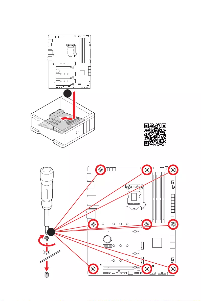
Installing the Motherboard
1
2
⚽
Torque:
3 kgf·cm*
*3 kgf·cm
= 0.3 N·m
= 2.6 lbf·in
8Quick Start
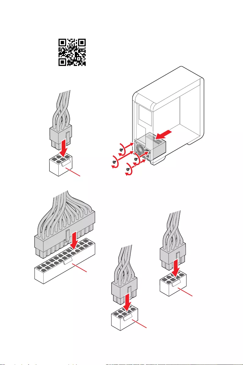
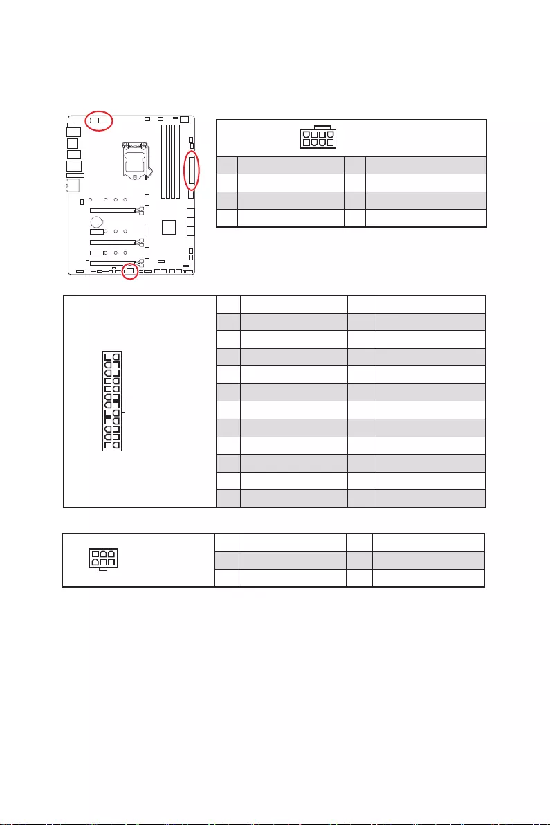
Connecting the Power Connectors
ATX_PWR1
CPU_PWR1
⚽
CPU_PWR2
PCIE_PWR1
9
Quick Start
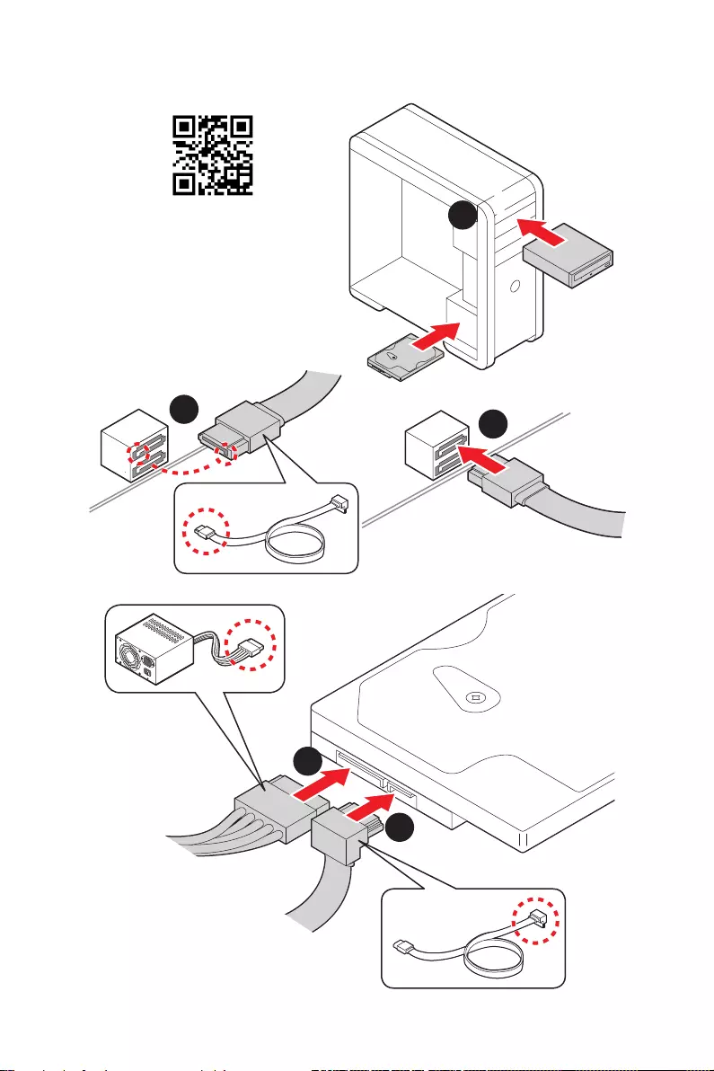
Installing SATA Drives
1
23
4
5
⚽
10 Quick Start
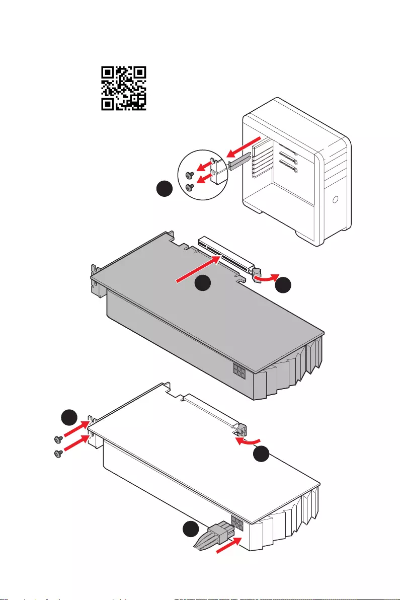
1
Installing a Graphics Card
2
3
4
5
6
⚽
11
Quick Start
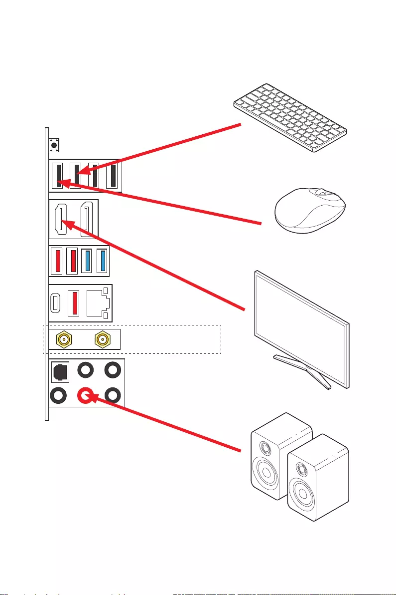
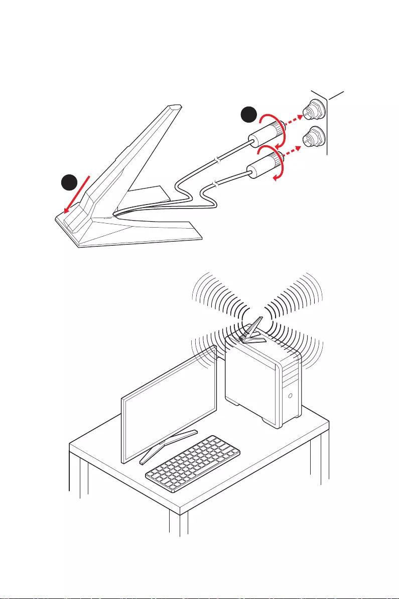
Connecting Peripheral Devices
(MPG Z590 GAMING CARBON WIFI)
12 Quick Start
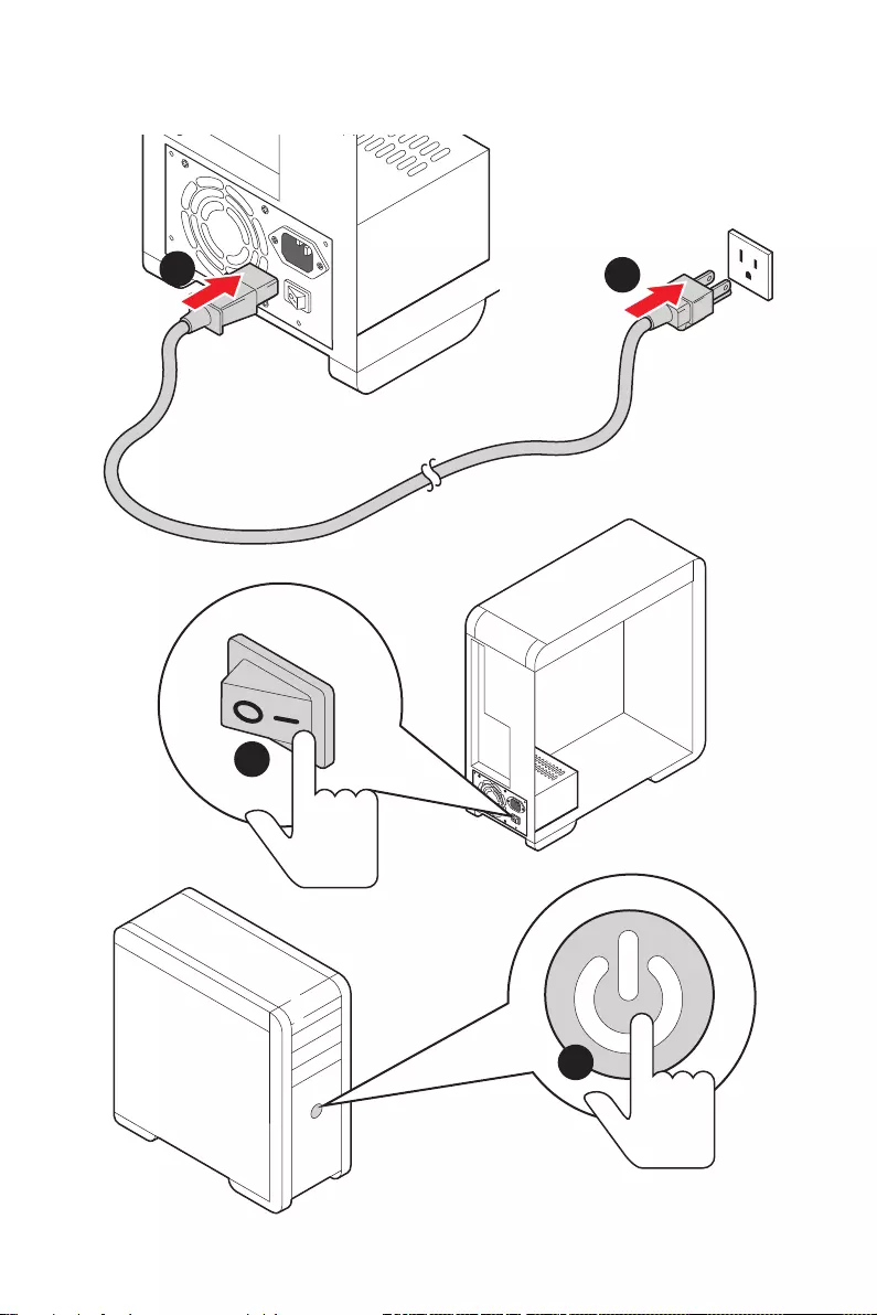
Power On
4
3
12

13
Contents
Contents
Quick Start ………………………………………………………………………………………………. 1
Preparing Tools and Components……………………………………………………………….. 1
Safety Information …………………………………………………………………………………….. 2
Case stand-off notification …………………………………………………………………………. 3
Installing a Processor ……………………………………………………………………………….. 4
Installing DDR4 memory ……………………………………………………………………………. 5
Connecting the Front Panel Header ……………………………………………………………. 6
Installing the Motherboard …………………………………………………………………………. 7
Connecting the Power Connectors ……………………………………………………………… 8
Installing SATA Drives ……………………………………………………………………………….. 9
Installing a Graphics Card ………………………………………………………………………… 10
Connecting Peripheral Devices …………………………………………………………………. 11
Power On ……………………………………………………………………………………………….. 12
Specifications …………………………………………………………………………………………. 15
Package contents …………………………………………………………………………………… 21
Block Diagram ………………………………………………………………………………………. 22
Rear I/O Panel ……………………………………………………………………………………….. 23
LAN Port LED Status Table ………………………………………………………………………. 23
Audio Ports Configuration ………………………………………………………………………… 23
Realtek Audio Console …………………………………………………………………………….. 24
Installing Antennas ………………………………………………………………………………….. 26
Overview of Components ………………………………………………………………………… 27
CPU Socket …………………………………………………………………………………………….. 29
DIMM Slots ……………………………………………………………………………………………… 30
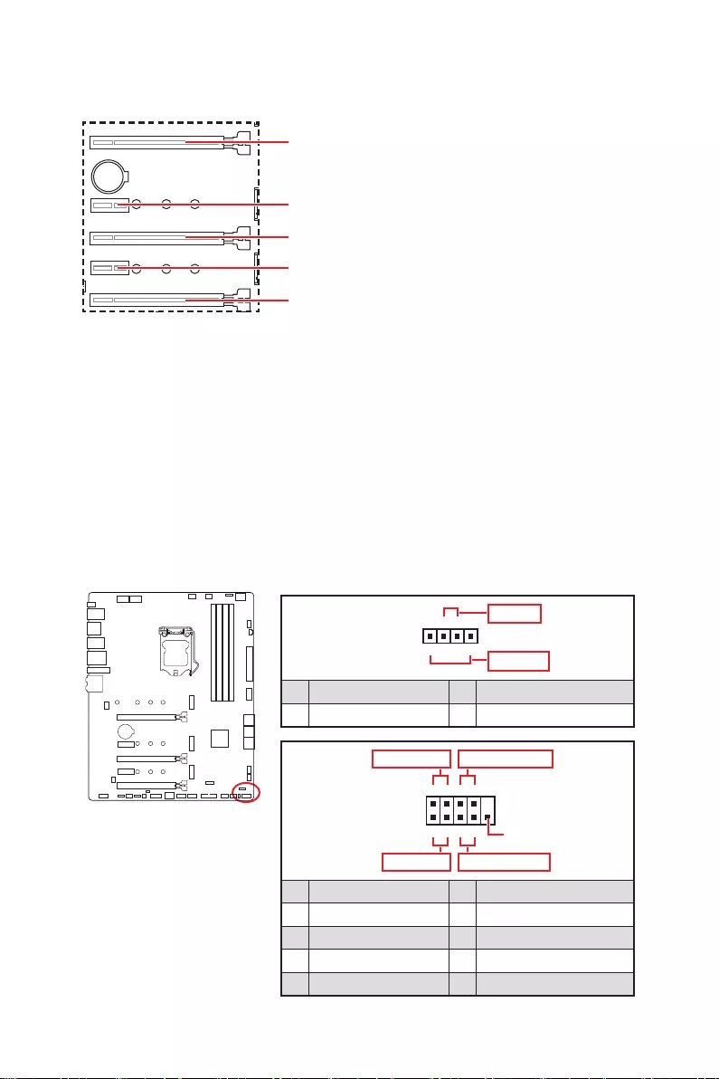
PCI_E1~5: PCIe Expansion Slots ……………………………………………………………….. 31
JFP1, JFP2: Front Panel Connectors …………………………………………………………. 31
M2_1~3: M.2 Slots (Key M) ……………………………………………………………………….. 32
SATA1~6: SATA 6Gb/s Connectors …………………………………………………………….. 34
JAUD1: Front Audio Connector …………………………………………………………………. 35
JTBT1: Thunderbolt Add-on Card Connector ……………………………………………… 35
CPU_PWR1~2, ATX_PWR1, PCIE_PWR1: Power Connectors ……………………….. 36
JDASH1 : Tuning Controller connector ………………………………………………………. 37
JCI1: Chassis Intrusion Connector …………………………………………………………….. 37
JUSB4: USB 3.2 Gen 2 Type-C Connector …………………………………………………… 38
JUSB3: USB 3.2 Gen 1 Connector ……………………………………………………………… 38
JUSB1~2: USB 2.0 Connectors ………………………………………………………………….. 39
JTPM1: TPM Module Connector ………………………………………………………………… 39

14 Contents
CPU_FAN1, PUMP_FAN1, SYS_FAN1~6: Fan Connectors ……………………………. 40
JBAT1: Clear CMOS (Reset BIOS) Jumper ………………………………………………….. 41
JRGB1: RGB LED connector ……………………………………………………………………… 42
JRAINBOW1~2: Addressable RGB LED connectors …………………………………….. 43
JCORSAIR1: CORSAIR Connector ……………………………………………………………… 44
Onboard LEDs ………………………………………………………………………………………… 45
EZ Debug LED …………………………………………………………………………………………. 45
JPWRLED1: LED power input ……………………………………………………………………. 45
LED_SW1: EZ LED Control ……………………………………………………………………….. 46
Debug Code LED ……………………………………………………………………………………… 46
Hexadecimal Character Table …………………………………………………………………… 46
Boot Phases ……………………………………………………………………………………………. 46
Debug Code LED Table …………………………………………………………………………….. 47
ACPI States Codes …………………………………………………………………………………… 51
CPU Temperature ……………………………………………………………………………………. 51
Installing OS, Drivers & MSI Center ………………………………………………………….. 52
Installing Windows® 10 …………………………………………………………………………….. 52
Installing Drivers …………………………………………………………………………………….. 52
MSI Center ……………………………………………………………………………………………… 52
UEFI BIOS ………………………………………………………………………………………………. 53
BIOS Setup ……………………………………………………………………………………………… 54
Entering BIOS Setup ………………………………………………………………………………… 54
BIOS User Guide ……………………………………………………………………………………… 54
Resetting BIOS ………………………………………………………………………………………… 55
Updating BIOS …………………………………………………………………………………………. 55
RAID Configuration …………………………………………………………………………………. 57
Intel® Optane™ Memory Configuration …………………………………………………….. 58
Troubleshooting ……………………………………………………………………………………. 59

15
Specifications
Specifications
CPU
∙Supports 10th Gen Intel® Core™ Processors, 11th Gen
Intel® Core™ Processors, Pentium® Gold and Celeron®
Processors*
∙Processor socket LGA1200
* Please go to intel.com for compatibility information.
Chipset Intel® Z590 Chipset
Memory
∙4x DDR4 memory slots, support up to 128GB*
∙Supports 1R 2133/ 2666/ 2933 MHz for 10th Gen Intel®
CPU (by JEDEC & POR)
∙Supports 1R 2133/ 2666/ 2933/ 3200 MHz for 11th Gen
Intel® CPU (by JEDEC & POR)
∙Max overclocking frequency:
▪1DPC 1R Max speed up to 5200 MHz
▪1DPC 2R Max speed up to 4700+ MHz
▪2DPC 1R Max speed up to 4400+ MHz
▪2DPC 2R Max speed up to 4000+ MHz
∙Supports Dual-Channel mode
∙Supports non-ECC, un-buffered memory
∙Supports Intel® Extreme Memory Profile (XMP)
*Please refer to www.msi.com for more information on compatible memory
Expansion Slot
∙3x PCIe x16 slots
▪Support x16/x0/x4, x8/x8/x4, x8/x4+x4/x4
▪PCI_E1 & PCI_E3 slots (From CPU)
▫Support PCIe 4.0 for 11th Gen Intel® CPU
▫Support PCIe 3.0 for 10th Gen Intel® CPU
▪PCI_E5 slot (From Z590 Chipset)
▫Supports PCIe 3.0
∙2x PCIe 3.0 x1 slots (From Z590 Chipset)
Multi-GPU ∙Supports 3-Way AMD® CrossFire™ Technology
Onboard Graphics
∙1x HDMI 2.0b with HDR port, supports a maximum
resolution of 4K 60Hz*/**
∙1x DisplayPort 1.4 port, supports a maximum resolution of
4K 60Hz*/**
*Available only on processors featuring integrated graphics.
** Graphics specifications may vary depending on the CPU installed.
Continued on next column

16 Specifications
Continued from previous column
Storage
∙6x SATA 6Gb/s ports (From Z590 Chipset)
∙3x M.2 slots (Key M)
▪M2_1 slot (From CPU)
▫Available only on 11th Gen Intel® CPU
▫Supports PCIe 4.0 x4
▫Supports 2242/ 2260/ 2280/ 22110 storage devices
▪M2_2* & M2_3** slot (From Z590 Chipset)
▫Supports PCIe 3.0 x4
▫Supports SATA 6Gb/s
▫Supports 2242/ 2260/ 2280 storage devices
▫Intel® Optane™ Memory Ready***
∙Supports Intel® Smart Response Technology for Intel
Core™ processors
* SATA2 will be unavailable when installing M.2 SATA SSD in the M2_2 slot.
** SATA5 & SATA6 will be unavailable when installing M.2 SSD in the M2_3 slot.
*** Before using Intel® Optane™ memory modules, please ensure that you have
updated the drivers and BIOS to the latest version from MSI website.
RAID
∙Supports RAID 0, RAID 1 and RAID 10 for SATA storage
devices
∙Supports RAID 0 and RAID 1 for M.2 NVMe storage devices
USB
∙Intel® Z590 Chipset
▪1x USB3.2 Gen2x2 20Gbps port (Type-C port on the
back panel)
▪4x USB 3.2 Gen 2 10Gbps ports (3 Type-A port on the
back panel, 1 Type-C available through the internal
connector)
▪4x USB 3.2 Gen 1 5Gbps ports (2 Type-A ports on the
back panel, 2 Type-A ports available through the internal
connector)
∙Hub-GL850G
▪8x USB 2.0 ports (4 Type-A ports on the back panel, 4
Type-A ports available through internal connectors)
Audio Realtek® ALC4080 Codec
∙7.1-Channel High Definition Audio
LAN 1x Intel® I225V 2.5Gbps LAN controller
Continued on next column

17
Specifications
Continued from previous column
Wireless LAN &
Bluetooth® (For
MPG Z590 GAMING
CARBON WIFI only)
∙Intel® Wi-Fi 6E AX210
∙The Wireless module is pre-installed in the M.2 (Key-E
slot
∙Supports MU-MIMO TX/RX, 2.4GHz/ 6GHz (160MHz) up to
2.4Gbps
∙Supports 802.11 a/ b/ g/ n/ ac/ ax
∙Supports Bluetooth® 5.2, FIPS, FISMA
Internal Connectors
∙1x 24-pin ATX main power connector
∙2x 8-pin ATX 12V power connectors
∙1x 6-pin PCIE power connector
∙6x SATA 6Gb/s connectors
∙3x M.2 slots (M-Key)
∙1x USB 3.2 Gen 2 10Gbps Type-C port
∙1x USB 3.2 Gen 1 5Gbps connector (supports additional 2
USB 3.2 Gen 1 5Gbps ports)
∙2x USB 2.0 Type-A connectors (supports additional 4 USB
2.0 ports)
∙1x 4-pin CPU fan connector
∙1x 4-pin water-pump fan connector
∙6x 4-pin system fan connectors
∙1x Front panel audio connector
∙2x System panel connectors
∙1x Chassis Intrusion connector
∙1x Clear CMOS jumper
∙1x TPM module connector
∙1x TBT connector (supports RTD3)
∙1x Tuning Controller connector
LED Features
∙1x EZ LED Control switch
∙4x EZ Debug LED
∙1x 2-Digit Debug Code LED
∙1x 4-pin RGB LED connector
∙2x 3-pin RAINBOW LED connectors
∙1x 3-pin CORSAIR LED connector
Continued on next column

18 Specifications
Continued from previous column
Back Panel
Connectors
∙1x Flash BIOS Button
∙4x USB 2.0 Type-A ports
∙1x DisplayPort
∙1x HDMI port
∙2x USB 3.2 Gen 1 5Gbps Type-A ports
∙3x USB 3.2 Gen 2 10Gbps Type-A ports
∙1x USB 3.2 Gen 2×2 20Gbps Type-C port
∙1x 2.5G LAN (RJ45) port
∙2x Wi-Fi Antenna connectors (For MPG Z590 GAMING
CARBON WIFI only)
∙5x audio jacks
∙1x Optical S/PDIF OUT connector
I/O Controller NUVOTON NCT6687 Controller Chip
Hardware Monitor
∙CPU/ System/ Chipset temperature detection
∙CPU/ System/ Pump fan speed detection
∙CPU/ System/ Pump fan speed control
Form Factor ∙ATX Form Factor
∙12 in. x 9.6 in. (30.5 cm x 24.4 cm)
BIOS Features
∙1x 256 Mb flash
∙UEFI AMI BIOS
∙ACPI 6.2, SMBIOS 3.0
∙Multi-language
Software
∙MSI Center
∙MSI Sound Tune
∙Intel Extreme Tuning Utility
∙MSI App Player (BlueStacks)
∙Open Broadcaster Software (OBS)
∙CPU-Z MSI GAMING
∙Google Chrome™, Google Toolbar, Google Drive
∙Norton™ Internet Security Solution
Continued on next column

19
Specifications
Continued from previous column
MSI Center
Features
∙Gaming Mode
∙Creator Mode
∙Mystic Light
∙Ambient Link (For MPG Z590 GAMING CARBON WIFI only)
∙LAN Manager
∙User Scenario
∙Monitor
∙Frozr AI Cooling
∙True Color
∙Live Update
∙Speed Up
∙Super Charger
Special Features
∙Audio
▪Audio Boost 5
▪Sound Tune
∙Network
▪2.5G LAN
▪LAN Manager
▪Intel Wi-Fi (For MPG Z590 GAMING CARBON WIFI only)
∙Cooling
▪M.2 Shield Frozr
▪K7 thermal pad
▪Choke pad
▪Pump Fan
▪Smart Fan Control
Continued on next column

20 Specifications
Continued from previous column
Special Features
∙LED
▪Mystic Light
▪Mystic Light Extension (RAINBOW/RGB/CORSAIR)
▪Mystic Light SYNC
▪Ambient Link (For MPG Z590 GAMING CARBON WIFI
only)
▪EZ LED Control
▪EZ DEBUG LED
∙Performance
▪Lightning Gen 4 PCI-E Slot
▪Lightning Gen 4 M.2
▪Multi GPU-CrossFire Technology
▪DDR4 Boost
▪Core Boost
▪Game Boost
▪Lightning USB 20G
▪USB 3.2 Gen 2 10G
▪USB with Type A+C
▪Front USB Type-C
▪Dual CPU Power: 8+8 pin
▪SUPPLEMENTAL PCIE POWER CONNECTOR
▪Server PCB
▪2oz Copper thickened PCB
∙Protection
▪PCI-E Steel Armor
▪Pre-installed I/O Shielding
∙Experience
▪MSI Center
▪Frozr AI Cooling
▪Click BIOS 5
▪Flash BIOS Button
21
Package contents
Package contents
Please check the contents of your motherboard package. It should contain:
Motherboard MPG Z590 GAMING CARBON WIFI/ MPG Z590 GAMING
FORCE
Documentation User manual 1
Quick installation guide 1
Application USB drive with drivers & utilities 1
Cables
SATA 6Gb/s cables 1
LED JRGB Y cable 1
LED JCORSAIR cable 1
LED JRAINBOW cable 1
Accessories
Wi-Fi antenna (For MPG Z590 GAMING CARBON
WIFI only) 1
Case badge 1
M.2 screw + standoff (2 sets/pack) 1
M.2 screw + standoff (1 set/pack) 1
MPG sticker 1
SATA cable stickers 1
Product registration card 1
Gifts Small screwdriver set 1
Small brush 1
⚠
Important
If any of the above items are damaged or missing, please contact your retailer.
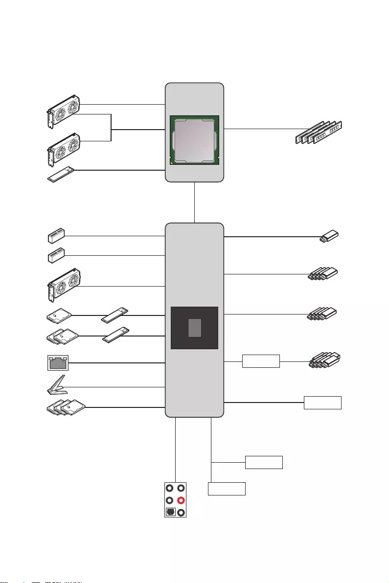
22 Block Diagram
Block Diagram
CPU
PCH
PCI_E1
PCIe x16
DDR4 2Channel
DIMM A1/A2
DIMM B1/B2
DMI x8
PCI_E3
PCIe x8
WiFi AX210
Intel LAN I225
HD Audio
ALC4080
M2_1
PCI_E2
PCI_E4
M2_2
M2_3
SATA5/6
SATA2
PCI_E5
PCIe x4
SIO 6687
TPM
SPI
MCU
USB 3.2 Gen 2 10Gbps
USB 3.2 Gen 1 5Gbps
USB 2.0
Hub-GL850G
USB3.2 Gen2x2 20Gbps
SATA1/3/4
23
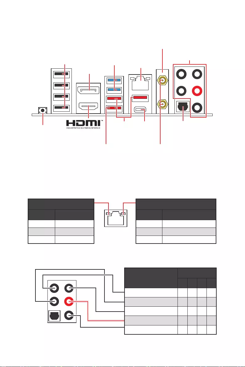
Rear I/O Panel
Audio Ports Configuration
Audio Ports Channel
2468
Center/ Sub-woofer Out
Rear Speaker Out
Line-In/ Side Speaker Out
Line-Out/ Front Speaker Out
Mic In
Blank: empty)
Rear I/O Panel
∙Flash BIOS Port/ Button — Please refer to page 56 for Updating BIOS with Flash
BIOS Button.
LAN Port LED Status Table
Link/ Activity LED
Status Description
Off No link
Yellow Linked
Blinking Data activity
Speed LED
Status Description
Off 10 Mbps connection
Green 100/1000 Mbps connection
Orange 2.5 Gbps connection
USB 3.2
Gen 2×2
(20Gbps)
Type-C
Flash BIOS
Button
2.5Gbps
LAN
Wi-Fi Antenna
connectors
USB 2.0
Type-A
USB 3.2
Gen 2
(10Gbps)
Type-A
USB 3.2
Gen 1
(5Gbps)
Type-A
DisplayPort
Audio Ports
(For MPG Z590 GAMING
CARBON WIFI only)
Optical
S/PDIF-Out
Flash BIOS
port
24 Rear I/O Panel
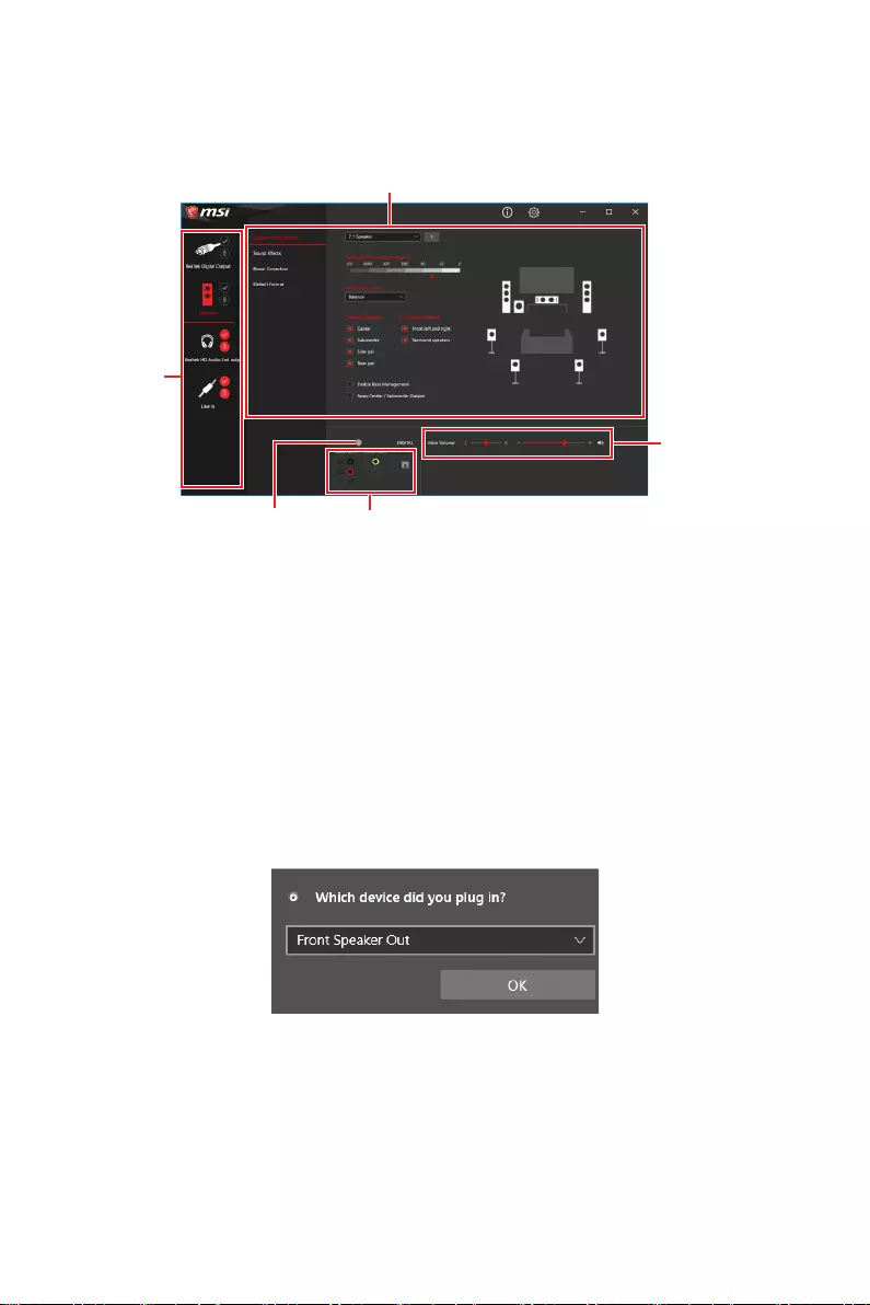
Realtek Audio Console
After Realtek Audio Console is installed. You can use it to change sound settings to get
better sound experience.
∙Device Selection — allows you to select a audio output source to change the related
options. The check sign indicates the devices as default.
∙Application Enhancement — the array of options will provide you a complete
guidance of anticipated sound effect for both output and input device.
∙Main Volume — controls the volume or balance the right/left side of the speakers
that you plugged in front or rear panel by adjust the bar.
∙Jack Status — depicts all render and capture devices currently connected with your
computer.
∙Connector Settings — configures the connection settings.
Auto popup dialog
When you plug into a device at an audio jack, a dialogue window will pop up asking you
which device is current connected.
Each jack corresponds to its default setting as shown on the next page.
⚠
Important
The pictures above for reference only and may vary from the product you purchased.
Jack Status
Connector Settings
Device
Selection
Main Volume
Application Enhancement
25
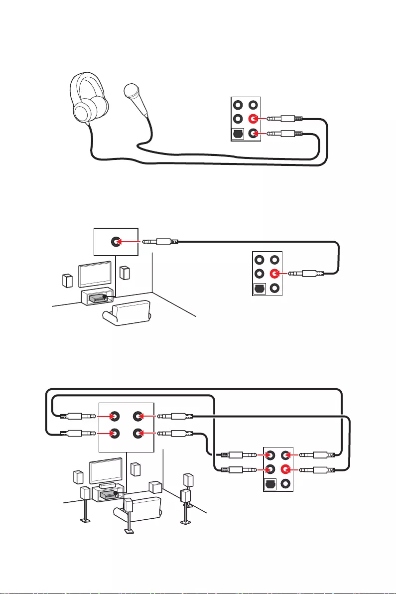
Rear I/O Panel
Audio jacks to headphone and microphone diagram
Audio jacks to stereo speakers diagram
Audio jacks to 7.1-channel speakers diagram
AUDIO INPUT
AUDIO INPUT
Rear Front
Side Center/
Subwoofer
26 Rear I/O Panel
Installing Antennas
1. Combine the antenna with the base.
2. Screw two antenna cables tight to the WiFi antenna connectors as shown.
1
2
3. Place the antenna as high as possible.
27
Overview of Components
Overview of Components
BAT1
JUSB3
JUSB4
ATX_PWR1
SYS_FAN6
JRAINBOW2
JCORSAIR1
PUMP_FAN1
CPU_FAN1
DIMMA1
Processor Socket
CPU_PWR1
CPU_PWR2
JFP1
JFP2
SYS_FAN5
SYS_FAN4
JTPM1
JCI1
JUSB2
JUSB1
LED_SW1
JTBT1
JDASH1
PCIE_PWR1
SYS_FAN3
SYS_FAN2
JRAINBOW1
JPWRLED1
JRGB1
JAUD1
PCI_E5
PCI_E4
PCI_E3
PCI_E2
M2_3
M2_2
PCI_E1
SYS_FAN1
M2_1
JBAT1
DIMMA2
DIMMB1
DIMMB2

28 Overview of Components
Component Contents
Port Name Port Type Page
CPU_FAN1, PUMP_FAN1,
SYS_FAN1~6 Fan Connectors 40
CPU_PWR1~2, ATX_PWR1,
PCIE_PWR1 Power Connectors 36
CPU Socket LGA1200 CPU Socket 29
DIMM Slots Memory slots 30
JAUD1 Front Audio Connector 35
JBAT1 Clear CMOS (Reset BIOS) Jumper 41
JCI1 Chassis Intrusion Connector 37
JCORSAIR1 CORSAIR Connector 44
JDASH1 Tuning Controller connector 37
JFP1, JFP2 Front Panel Connectors 31
JPWRLED1 LED power input 45
JRAINBOW1~2 Addressable RGB LED connectors 43
JRGB1 RGB LED connector 42
JTBT1 Thunderbolt Add-on Card Connector 35
JTPM1 TPM Module Connector 39
JUSB1~2 USB 2.0 Connectors 39
JUSB3 USB 3.2 Gen 1 Connector 38
JUSB4 USB 3.2 Gen 2 Type-C Connector 38
LED_SW1 EZ LED Control 46
M2_1~3 M.2 Slots (Key M) 32
PCI_E1~5 PCIe Expansion Slots 31
SATA1~6 SATA 6Gb/s Connectors 34
29
Overview of Components
⚠
Important
∙
Always unplug the power cord from the power outlet before installing or removing
the CPU.
∙
Please retain the CPU protective cap after installing the processor. MSI will deal
with Return Merchandise Authorization (RMA) requests if only the motherboard comes
with the protective cap on the CPU socket.
∙
When installing a CPU, always remember to install a CPU heatsink. A CPU heatsink
is necessary to prevent overheating and maintain system stability.
∙
Confirm that the CPU heatsink has formed a tight seal with the CPU before booting
your system.
∙
Overheating can seriously damage the CPU and motherboard. Always make sure
the cooling fans work properly to protect the CPU from overheating. Be sure to apply
an even layer of thermal paste (or thermal tape) between the CPU and the heatsink to
enhance heat dissipation.
∙
Whenever the CPU is not installed, always protect the CPU socket pins by covering
the socket with the plastic cap.
∙
If you purchased a separate CPU and heatsink/ cooler, Please refer to the
documentation in the heatsink/ cooler package for more details about installation.
∙
This motherboard is designed to support overclocking. Before attempting to
overclock, please make sure that all other system components can tolerate
overclocking. Any attempt to operate beyond product specifications is not
recommended. MSI® does not guarantee the damages or risks caused by inadequate
operation beyond product specifications.
CPU Socket
Introduction to the LGA1200 CPU
The surface of the LGA1200 CPU has
two notches and a golden triangle to
assist in correctly lining up the CPU for
motherboard placement. The golden
triangle is the Pin 1 indicator.
50.77 mm
Distance from the center of the
CPU to the nearest DIMM slot.
30 Overview of Components
DIMM Slots
DIMMA1 DIMMB1
Channel A Channel B
DIMMA2 DIMMB2
Memory module installation recommendation
⚠
Important
∙
Always insert memory modules in the DIMMA2 slot first.
∙
To ensure system stability for Dual channel mode, memory modules must be of the
same type, number and density.
∙
Some memory modules may operate at a lower frequency than the marked value
when overclocking due to the memory frequency operates dependent on its Serial
Presence Detect (SPD). Go to BIOS and find the DRAM Frequency to set the memory
frequency if you want to operate the memory at the marked or at a higher frequency.
∙
It is recommended to use a more efficient memory cooling system for full DIMMs
installation or overclocking.
∙
The stability and compatibility of installed memory module depend on installed CPU
and devices when overclocking.
∙
Please refer to www.msi.com for more information on compatible memory.
DIMMB2 DIMMB2
DIMMB1
DIMMA2 DIMMA2 DIMMA2
DIMMA1
31
Overview of Components
BAT1
PCI_E1~5: PCIe Expansion Slots
PCI_E1: PCIe 4.0 x16 (From CPU)
PCI_E3: PCIe 4.0 x8 (From CPU)
PCI_E2: PCIe 3.0 x1 (From Z590 chipset)
PCI_E5: PCIe 3.0 x4 (From Z590 chipset)
PCI_E4: PCIe 3.0 x1 (From Z590 chipset)
⚠
Important
∙
If you install a large and heavy graphics card, you need to use a tool such as MSI
Graphics Card Bolster to support its weight to prevent deformation of the slot.
∙
For a single PCIe x16 expansion card installation with optimum performance, using
the PCI_E1 slot is recommended.
∙
When adding or removing expansion cards, always turn off the power supply and
unplug the power supply power cable from the power outlet. Read the expansion
card’s documentation to check for any necessary additional hardware or software
changes.
JFP1, JFP2: Front Panel Connectors
These connectors connect to the switches and LEDs on the front panel.
1
2 10
9
+
+
+— ——
—
+
Power LED
HDD LED Reset Switch
Reserved
Power Switch
JFP1
1 HDD LED + 2 Power LED +
3 HDD LED — 4 Power LED —
5 Reset Switch 6 Power Switch
7 Reset Switch 8 Power Switch
9 Reserved 10 No Pin
1
JFP2
+
+—
—
Speaker
Buzzer
1 Speaker — 2 Buzzer +
3 Buzzer — 4 Speaker +
32 Overview of Components
Installing M.2 module
1. Loosen the screws of M.2 SHIELD FROZR heatsink.
2. Remove the M.2 SHIELD FROZR and remove the protective films from the thermal
pads.
2
2
2
1
1
1
1
11
1
1
M2_1
M2_2
M2_3
M2_1~3: M.2 Slots (Key M)
M2_1
M2_2
M2_3
⚠
Important
∙
Intel® RST only supports PCIe M.2 SSD with UEFI ROM.
∙
Intel® Optane™ Memory Ready for M2_2 and M2_3 slots.
⚽
Video Demonstration
Watch the video to learn how to Install
M.2 SSD.
33
Overview of Components
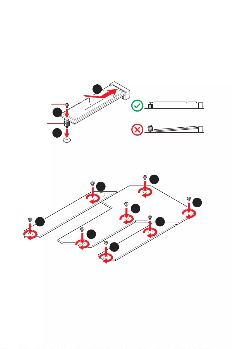
3. Secure the supplied M.2 standoff according to your M.2 SSD length if need.
4. Insert your M.2 SSD into the M.2 slot at a 30-degree angle.
5. Secure the M.2 SSD in place with the supplied M.2 8.5H screw.
⚠
Important
Skip step 3 and step 5, if you install 22110 M.2 into M2_1 slot or 2280 M.2 into M2_2
and M2_3 slots.
6. Put the M.2 SHIELD FROZR heatsink back in place and secure it.
30º30º
5
4
3
8.5H screw
Standoff
6
6
6
6
6
6
6
6
34 Overview of Components
M.2 & SATA combination table
Slot Available SATA connectors
M2_1 PCIe (M2_1 slot is only available on 11th Gen Intel® CPU)
M2_2 PCIe SATA PCIe SATA PCIe SATA
M2_3 PCIe PCIe SATA SATA
SATA1
SATA2
SATA3
SATA4
SATA5
SATA6
(SATA: M.2 SATA SSD, PCIe
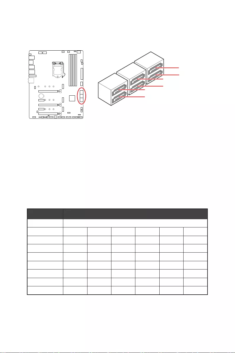
SATA1~6: SATA 6Gb/s Connectors
These connectors are SATA 6Gb/s interface ports. Each connector can connect to one
SATA device.
SATA1
SATA3
SATA5
SATA2
SATA4
SATA6
⚠
Important
∙
Please do not fold the SATA cable at a 90-degree angle. Data loss may result during
transmission otherwise.
∙
SATA cables have identical plugs on either sides of the cable. However, it is
recommended that the flat connector be connected to the motherboard for space
saving purposes.
∙
SATA2 will be unavailable when installing M.2 SATA SSD in the M2_2 slot.
∙
SATA5 & SATA6 will be unavailable when installing M.2 SATA/PCIe SSD in the M2_3
slot.
35
Overview of Components
JAUD1: Front Audio Connector
This connector allows you to connect audio jacks on the front panel.
1
2 10
9
1 MIC L 2 Ground
3 MIC R 4 NC
5 Head Phone R 6 MIC Detection
7 SENSE_SEND 8 No Pin
9 Head Phone L 10 Head Phone Detection
JTBT1: Thunderbolt Add-on Card Connector
This connector allows you to connect the add-on Thunderbolt I/O card.
1
2 16
15
1 TBT_FORCE_PWR 2 TBT_S0IX_ENTRY_REQ
3 TBT_CIO_PLUG_EVENT# 4 TBT_S0IX_ENTRY_ACK
5 SLP_S3#_TBT 6 TBT_PSON_OVERRIDE_N
7 SLP_S5#_TBT 8 No Pin
9 Ground 10 SMBCLK_VSB
11 DG_PEWAKE# 12 SMBDATA_VSB
13 TBT_RTD3_PWR_EN 14 Ground
15 TBT_CARD_DET_R# 16 PD_IRQ#
36 Overview of Components
24
131
12
ATX_PWR1
1 +3.3V 13 +3.3V
2 +3.3V 14 -12V
3 Ground 15 Ground
4 +5V 16 PS-ON#
5 Ground 17 Ground
6 +5V 18 Ground
7 Ground 19 Ground
8 PWR OK 20 Res
9 5VSB 21 +5V
10 +12V 22 +5V
11 +12V 23 +5V
12 +3.3V 24 Ground
5
4 1
8CPU_PWR1~2
1 Ground 5 +12V
2 Ground 6 +12V
3 Ground 7 +12V
4 Ground 8 +12V
⚠
Important
Make sure that all the power cables are securely connected to a proper ATX power
supply to ensure stable operation of the motherboard.
CPU_PWR1~2, ATX_PWR1, PCIE_PWR1: Power Connectors
These connectors allow you to connect an ATX power supply.
1 3
64
PCIE_PWR1
1 +12V 4 Ground
2 +12V 5 Ground
3 +12V 6 Ground
37
Overview of Components
JDASH1 : Tuning Controller connector
This connector is used to connect an optional Tuning Controller module.
1
2
65
1 No Pin 2 NC
3 MCU_SMB_SCL_M 4 MCU_SMB_SDA_M
5 VCC5 6 Ground
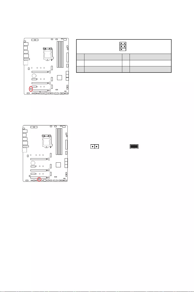
JCI1: Chassis Intrusion Connector
This connector allows you to connect the chassis intrusion switch cable.
Normal
(default) Trigger the chassis
intrusion event
Using chassis intrusion detector
1. Connect the JCI1 connector to the chassis intrusion switch/ sensor on the chassis.
2. Close the chassis cover.
3. Go to BIOS > SETTINGS > Security > Chassis Intrusion Configuration.
4. Set Chassis Intrusion to Enabled.
5. Press F10 to save and exit and then press the Enter key to select Yes.
6. Once the chassis cover is opened again, a warning message will be displayed on
screen when the computer is turned on.
Resetting the chassis intrusion warning
1. Go to BIOS > SETTINGS > Security > Chassis Intrusion Configuration.
2. Set Chassis Intrusion to Reset.
3. Press F10 to save and exit and then press the Enter key to select Yes.
38 Overview of Components
JUSB3: USB 3.2 Gen 1 Connector
This connector allows you to connect USB 3.2 Gen 1 5Gbps ports on the front panel.
⚠
Important
Note that the Power and Ground pins must be connected correctly to avoid possible
damage.
110
11
20
1 Power 11 USB2.0+
2 USB3_RX_DN 12 USB2.0-
3 USB3_RX_DP 13 Ground
4 Ground 14 USB3_TX_C_DP
5 USB3_TX_C_DN 15 USB3_TX_C_DN
6 USB3_TX_C_DP 16 Ground
7 Ground 17 USB3_RX_DP
8 USB2.0- 18 USB3_RX_DN
9 USB2.0+ 19 Power
10 Ground 20 No Pin
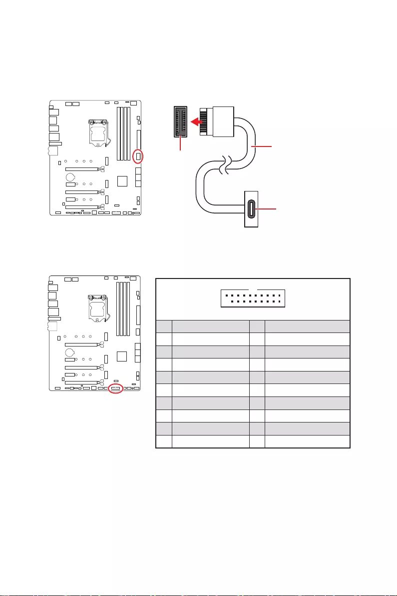
JUSB4: USB 3.2 Gen 2 Type—C Connector
This connector allows you to connect USB 3.2 Gen 2 Type-C connector on the front
panel. The connector possesses a foolproof design. When you connect the cable, be
sure to connect it with the corresponding orientation.
JUSB1 USB Type-C Cable
USB Type-C port on
the front panel
39
Overview of Components
JUSB1~2: USB 2.0 Connectors
These connectors allow you to connect USB 2.0 ports on the front panel.
1
2 10
9
1 VCC 2 VCC
3 USB0- 4 USB1-
5 USB0+ 6 USB1+
7 Ground 8 Ground
9 No Pin 10 NC
⚠
Important
∙
Note that the VCC and Ground pins must be connected correctly to avoid possible
damage.
∙
In order to recharge your iPad, iPhone and iPod through USB ports, please install
MSI® Center utility.
1
2 12
11
1 SPI Power 2 SPI Chip Select
3
Master In Slave Out (SPI Data)
4
Master In Slave In (SPI Data)
5 Reserved 6 SPI Clock
7 Ground 8 SPI Reset
9 Reserved 10 No Pin
11 Reserved 12 Interrupt Request
JTPM1: TPM Module Connector
This connector is for TPM (Trusted Platform Module). Please refer to the TPM security
platform manual for more details and usages.
40 Overview of Components
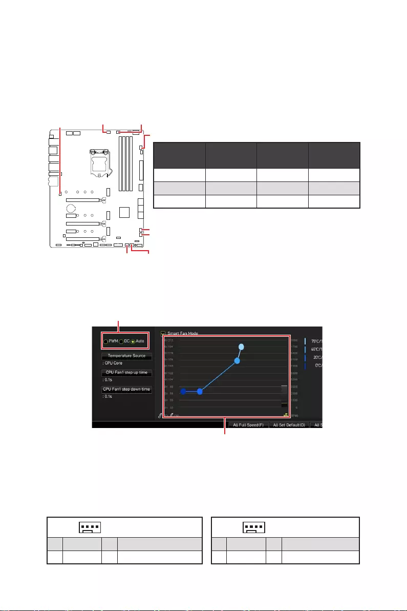
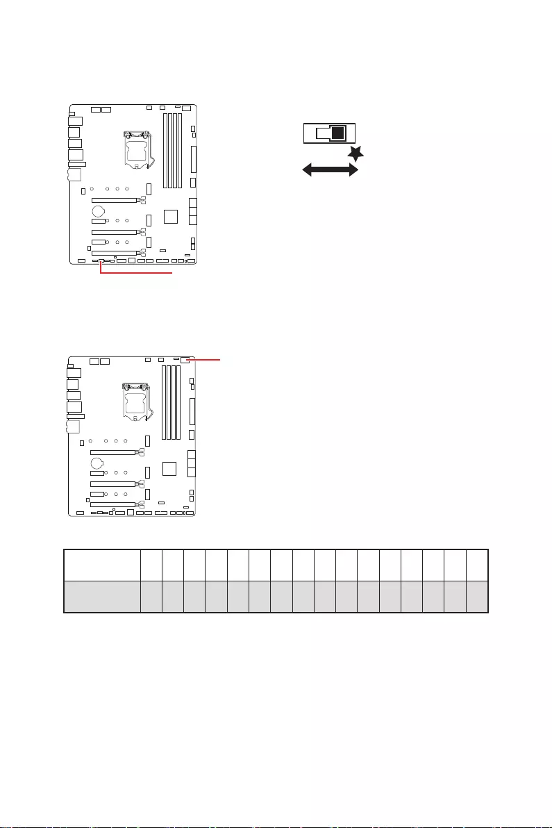
CPU_FAN1, PUMP_FAN1, SYS_FAN1~6: Fan Connectors
Fan connectors can be classified as PWM (Pulse Width Modulation) Mode or DC Mode.
PWM Mode fan connectors provide constant 12V output and adjust fan speed with
speed control signal. DC Mode fan connectors control fan speed by changing voltage.
The auto mode fan connectors can automatically detect PWM and DC mode. However,
you can follow the instruction below to adjust the fan connector to PWM or DC Mode
manually.
Switching fan mode and adjusting fan speed
You can switch between PWM mode and DC mode and adjust fan speed in BIOS >
HARDWARE MONITOR.
Select PWM mode or DC mode
⚠
Important
Make sure fans are working properly after switching the PWM/ DC mode.
There are gradient points of the fan speed that allow you to adjust
fan speed in relation to CPU temperature.
Pin definition of fan connectors
CPU_FAN1
SYS_FAN2 SYS_FAN3
SYS_FAN4
SYS_FAN5
PUMP_FAN1
SYS_FAN6
SYS_FAN1
Connector Default fan
mode Max.
current Max.
power
CPU_FAN1 Auto mode 2A 24W
PUMP_FAN1 PWM mode 3A 36W
SYS_FAN1~6 DC mode 1A 12W
1 PWM Mode pin definition
1 Ground 2 +12V
3 Sense 4 Speed Control Signal
1 DC Mode pin definition
1 Ground 2 Voltage Control
3 Sense 4 NC

41
Overview of Components
JBAT1: Clear CMOS (Reset BIOS) Jumper
There is CMOS memory onboard that is external powered from a battery located on
the motherboard to save system configuration data. If you want to clear the system
configuration, set the jumpers to clear the CMOS memory.
Keep Data
(default) Clear CMOS/
Reset BIOS
Resetting BIOS to default values
1. Power off the computer and unplug the power cord.
2. Use a jumper cap to short JBAT1 for about 5-10 seconds.
3. Remove the jumper cap from JBAT1.
4. Plug the power cord and Power on the computer.
42 Overview of Components
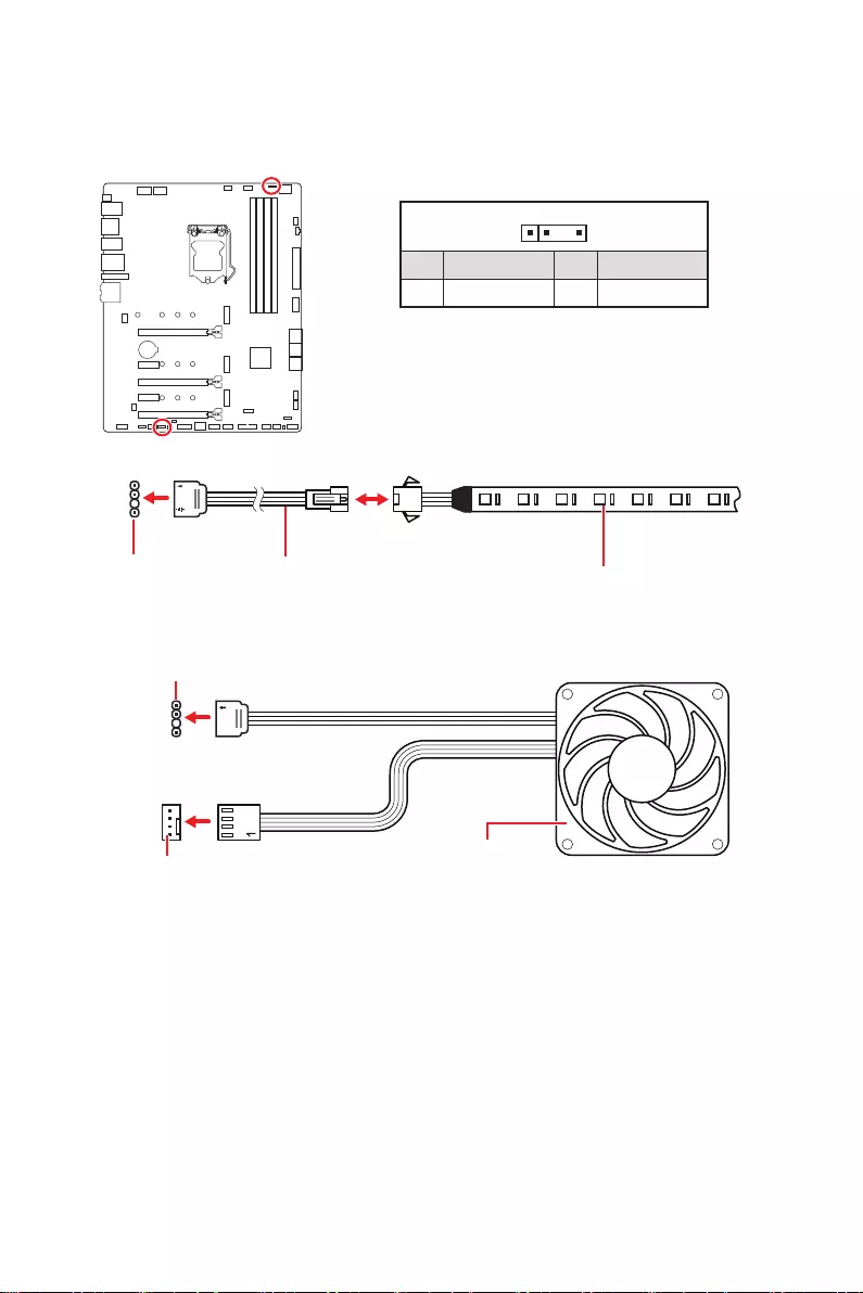
⚠
Important
∙
The JRGB connector supports up to 2 meters continuous 5050 RGB LED strips
(12V/G/R/B) with the maximum power rating of 3A (12V).
∙
Always turn off the power supply and unplug the power cord from the power outlet
before installing or removing the RGB LED strip.
∙
Please use MSI’s software to control the extended LED strip.
JRGB1: RGB LED connector
The JRGB connector allows you to connect the 5050 RGB LED strips 12V.
1
GRB
JRGB
connector
RGB extension
cable 5050 RGB LED strips 12V
1
1 +12V 2 G
3 R 4 B
RGB LED Strip Connection
1
1
GRB
JRGB connector
System Fan connector
RGB LED Fan Connection
RGB LED Fan
43
Overview of Components
1
1
1
D
+5V
⚠
CAUTION
Do not connect the wrong type of LED strips. The JRGB connector and the JRAINBOW
connector provide different voltages, and connecting the 5V LED strip to the JRGB
connector will result in damage to the LED strip.
⚠
Important
∙
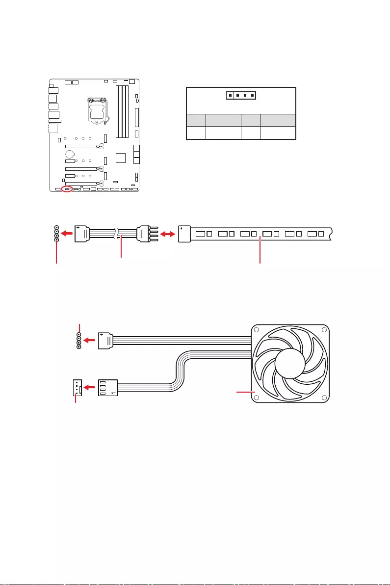
The JRAINBOW connector supports up to 75 LEDs WS2812B Individually
Addressable RGB LED strips (5V/Data/Ground) with the maximum power rating of 3A
(5V). In the case of 20% brightness, the connector supports up to 200 LEDs.
∙
Always turn off the power supply and unplug the power cord from the power outlet
before installing or removing the RGB LED strip.
∙
Please use MSI’s software to control the extended LED strip.
JRAINBOW1~2: Addressable RGB LED connectors
The JRAINBOW connectors allow you to connect the WS2812B Individually
Addressable RGB LED strips 5V.
JRAINBOW
connector
JRAINBOW connector
System Fan connector
Rainbow RGB LED
extension cable WS2812B Individually
Addressable RGB LED strips 5V
1
1 +5V 2 Data
3 No Pin 4 Ground
Addressable RGB LED Strip Connection
Addressable RGB LED Fan Connection
Addressable RGB LED Fan
44 Overview of Components
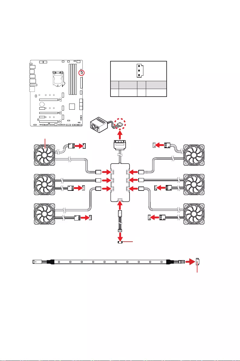
JCORSAIR1: CORSAIR Connector
The JCORSAIR1 connector allows you to connect the CORSAIR Individually
Addressable Lighting PRO RGB LED strips 5V or CORSAIR RGB fans with the CORSAIR
fan hub. Once all items are connected properly, you can control the CORSAIR RGB
LED strips and fans with MSI’s software.
1
1 +5V 2 Data
3 Ground
CORSAIR RGB Fan Connection
⚠
Important
∙
Fans must start at 1 and continue in series. 1 > 2 > 3 > 4 > 5 > 6. Any fan not
connected in series will break communication and the RGB LED lighting function will
not work.
∙
Quantity of RGB LED Fans or RGB LED Lighting PRO strips supported may differ
between models. Please refer to the motherboard specification.
∙
CORSAIR RGB LED Fan and CORSAIR Lighting Node PRO can’t be used at the same
time.
JCORSAIR1 connector
SYS_FAN
SYS_FAN
SYS_FAN SYS_FAN
SYS_FAN
SYS_FAN
1
2
34
5
6
JCORSAIR1 connector
SATA power
CORSAIR Lighting Node PRO Connection
CORSAIR RGB LED fan
CORSAIR fan hub
45
Onboard LEDs
EZ Debug LED
These LEDs indicate the debug status of the motherboard.
CPU — indicates CPU is not detected or fail.
DRAM — indicates DRAM is not detected or fail.
VGA — indicates GPU is not detected or fail.
BOOT — indicates the booting device is not detected
or fail.
Onboard LEDs
JPWRLED1: LED power input
This connector is used by retailers to demonstrate onboard LED lights.
JPWRLED1 — LED power input
46 Onboard LEDs
Debug Code LED
Debug Code LED
The Debug Code LED displays progress and error codes during and after POST. Refer
to the Debug Code LED table for details.
LED_SW1: EZ LED Control
This switch is used to switch on/ off all the LEDs of motherboard.
LED_SW1
Hexadecimal Character Table
Hexadecimal 0 1 2 3 4 5 6 7 8 9 A B C D E F
Debug Code
LED display 0123456789ABCDEF
Boot Phases
Security (SEC) – initial low-level initialization
Pre-EFI Initialization (PEI) – memory initialization
Driver Execution Environment (DXE) – main hardware initialization
Boot Device Selection (BDS) – system setup, pre-OS user interface & selecting a
bootable device (CD/DVD, HDD, USB, Network, Shell, …)
LED_OFF LED_ON
(Default)
47
Onboard LEDs
Debug Code LED Table
SEC Progress Codes
01 Power on. Reset type detection (soft/hard)
02 AP initialization before microcode loading
03 System Agent initialization before microcode loading
04 PCH initialization before microcode loading
06 Microcode loading
07 AP initialization after microcode loading
08 System Agent initialization after microcode loading
09 PCH initialization after microcode loading
0B Cache initialization
SEC Error Codes
0C — 0D Reserved for future AMI SEC error codes
0E Microcode not found
0F Microcode not loaded
PEI Progress Codes
10 PEI Core is started
11 Pre-memory CPU initialization is started
12 — 14 Pre-memory CPU initialization (CPU module specific)
15 Pre-memory System Agent initialization is started
16 — 18 Pre-Memory System Agent initialization (System Agent module specific)
19 Pre-memory PCH initialization is started
1A — 1C Pre-memory PCH initialization (PCH module specific)
2B Memory initialization. Serial Presence Detect (SPD) data reading
2C Memory initialization. Memory presence detection
2D Memory initialization. Programming memory timing information
2E Memory initialization. Configuring memory
2F Memory initialization (other)
31 Memory Installed
32 CPU post-memory initialization is started
33 CPU post-memory initialization. Cache initialization
34 CPU post-memory initialization. Application Processor(s) (AP) initialization
35 CPU post-memory initialization. Boot Strap Processor (BSP) selection
36 CPU post-memory initialization. System Management Mode (SMM) initialization
37 Post-Memory System Agent initialization is started
38 — 3A Post-Memory System Agent initialization (System Agent module specific)
3B Post-Memory PCH initialization is started
48 Onboard LEDs
3C — 3E Post-Memory PCH initialization (PCH module specific)
4F DXE IPL is started
PEI Error Codes
50 Memory initialization error. Invalid memory type or incompatible memory speed
51 Memory initialization error. SPD reading has failed
52 Memory initialization error. Invalid memory size or memory modules do not match
53 Memory initialization error. No usable memory detected
54 Unspecified memory initialization error
55 Memory not installed
56 Invalid CPU type or Speed
57 CPU mismatch
58 CPU self test failed or possible CPU cache error
59 CPU micro-code is not found or micro-code update is failed
5A Internal CPU error
5B Reset PPI is not available
5C — 5F Reserved for future AMI error codes
DXE Progress Codes
60 DXE Core is started
61 NVRAM initialization
62 Installation of the PCH Runtime Services
63 CPU DXE initialization is started
64 — 67 CPU DXE initialization (CPU module specific)
68 PCI host bridge initialization
69 System Agent DXE initialization is started
6A System Agent DXE SMM initialization is started
6B — 6F System Agent DXE initialization (System Agent module specific)
70 PCH DXE initialization is started
71 PCH DXE SMM initialization is started
72 PCH devices initialization
73 — 77 PCH DXE Initialization (PCH module specific)
78 ACPI module initialization
79 CSM initialization
7A — 7F Reserved for future AMI DXE codes
90 Boot Device Selection (BDS) phase is started
91 Driver connecting is started
92 PCI Bus initialization is started
93 PCI Bus Hot Plug Controller Initialization
94 PCI Bus Enumeration 32

49
Onboard LEDs
95 PCI Bus Request Resources
96 PCI Bus Assign Resources
97 Console Output devices connect
98 Console input devices connect
99 Super IO Initialization
9A USB initialization is started
9B USB Reset
9C USB Detect
9D USB Enable
9E -9F Reserved for future AMI codes
A0 IDE initialization is started
A1 IDE Reset
A2 IDE Detect
A3 IDE Enable
A4 SCSI initialization is started
A5 SCSI Reset
A6 SCSI Detect
A7 SCSI Enable
A8 Setup Verifying Password
A9 Start of Setup
AB Setup Input Wait
AD Ready To Boot event
AE Legacy Boot event
AF Exit Boot Services event
B0 Runtime Set Virtual Address MAP Begin
B1 Runtime Set Virtual Address MAP End
B2 Legacy Option ROM Initialization
B3 System Reset
B4 USB hot plug
B5 PCI bus hot plug
B6 Clean-up of NVRAM
B7 Configuration Reset (reset of NVRAM settings)
B8 — BF Reserved for future AMI codes
DXE Error Codes
D0 CPU initialization error
D1 System Agent initialization error
D2 PCH initialization error
D3 Some of the Architectural Protocols are not available
50 Onboard LEDs
D4 PCI resource allocation error. Out of Resources
D5 No Space for Legacy Option ROM
D6 No Console Output Devices are found
D7 No Console Input Devices are found
D8 Invalid password
D9 Error loading Boot Option (LoadImage returned error)
DA Boot Option is failed (StartImage returned error)
DB Flash update is failed
DC Reset protocol is not available
S3 Resume Progress Codes
E0 S3 Resume is stared (S3 Resume PPI is called by the DXE IPL)
E1 S3 Boot Script execution
E2 Video repost
E3 OS S3 wake vector call
E4 — E7 Reserved for future AMI progress codes
S3 Resume Error Codes
E8 S3 Resume Failed
E9 S3 Resume PPI not Found
EA S3 Resume Boot Script Error
EB S3 OS Wake Error
EC — EF Reserved for future AMI error codes
Recovery Progress Codes
F0 Recovery condition triggered by firmware (Auto recovery)
F1 Recovery condition triggered by user (Forced recovery)
F2 Recovery process started
F3 Recovery firmware image is found
F4 Recovery firmware image is loaded
F5 — F7 Reserved for future AMI progress codes
Recovery Error Codes
F8 Recovery PPI is not available
F9 Recovery capsule is not found
FA Invalid recovery capsule
FB — FF Reserved for future AMI error codes
51
Onboard LEDs
ACPI States Codes
The following codes appear after booting and the operating system into ACPI modes.
01 System is entering S1 sleep state
02 System is entering S2 sleep state
03 System is entering S3 sleep state
04 System is entering S4 sleep state
05 System is entering S5 sleep state
10 System is waking up from the S1 sleep state
20 System is waking up from the S2 sleep state
30 System is waking up from the S3 sleep state
40 System is waking up from the S4 sleep state
AC System has transitioned into ACPI mode. Interrupt controller is in PIC
mode.
AA System has transitioned into ACPI mode. Interrupt controller is in APIC
mode.
CPU Temperature
00 — 99 Displays current CPU temperature after the system has fully booted into the OS.

52 Installing OS, Drivers & MSI Center
Installing OS, Drivers & MSI Center
Please download and update the latest utilities and drivers at www.msi.com
Installing Windows® 10
1. Power on the computer.
2. Insert the Windows® 10 installation disc/USB into your computer.
3. Press the Restart button on the computer case.
4. Press F11 key during the computer POST (Power-On Self Test) to get into Boot
Menu.
5. Select the Windows® 10 installation disc/USB from the Boot Menu.
6. Press any key when screen shows Press any key to boot from CD or DVD…
message.
7. Follow the instructions on the screen to install Windows® 10.
Installing Drivers
1. Start up your computer in Windows® 10.
2. Insert MSI® USB Drive into the USB port.
3. Click the Select to choose what happens with this disc pop-up notification, then
select Run DVDSetup.exe to open the installer. If you turn off the AutoPlay feature
from the Windows Control Panel, you can still manually execute the DVDSetup.exe
from the root path of the MSI USB Drive.
4. The installer will find and list all necessary drivers in the Drivers/Software tab.
5. Click the Install button in the lower-right corner of the window.
6. The drivers installation will then be in progress, after it has finished it will prompt
you to restart.
7. Click OK button to finish.
8. Restart your computer.
MSI Center
MSI Center is an application that helps you easily optimize game settings and smoothly
use content creation softwares. It also allows you to control and synchronize LED
light effects on PCs and other MSI products. With MSI Center, you can customize ideal
modes, monitor system performance, and adjust fan speed.
MSI Center User Guide
If you would like to know more information about MSI Center, please
refer to
http://download.msi.com/manual/mb/MSICENTER.pdf
or scan the QR code to access.
⚠
Important
Functions may vary depending on the product you have.

53
UEFI BIOS
UEFI BIOS
MSI UEFI BIOS is compatible with UEFI (Unified Extensible Firmware Interface)
architecture. The UEFI BIOS firmware infrastructure has many new functions and
advantages that traditional BIOS cannot achieve. It will fully support future PCs and
devices that comply with UEFI firmware architecture.
⚠
Important
The term BIOS in this user guide refers to UEFI BIOS unless otherwise noted.
UEFI advantages
∙Fast booting — UEFI can directly boot the operating system and save the BIOS self-
test process. And also eliminates the time to switch to CSM mode during POST
∙Supports for hard drive partitions larger than 2 TB.
∙Supports more than 4 primary partitions with a GUID Partition Table (GPT).
∙Supports unlimited number of partitions
∙Supports full capabilities of new devices — new devices may not provide backward
compatibility.
∙Supports secure startup — UEFI can check the validity of the operating system to
ensure that no malware tampers with the startup process.
Incompatible UEFI cases
∙32-bit Windows operating system — this motherboard supports only 64-bit Windows
10 operating system.
∙Older graphics card — the system will detect your graphics card. When display a
warning message There is no GOP (Graphics Output protocol) support detected in
this graphics card.
⚠
Important
We recommend that you to replace with a GOP/UEFI compatible graphics card or
using integrated graphics from CPU for having normal function..
How to check the BIOS mode?
1. Power on your computer.
2. Press Delete key, when the Press DEL key to enter Setup Menu, F11 to enter
Boot Menu message appears on the screen during the boot process.
3. After entering the BIOS, you can check the BIOS Mode at the top of the screen.
BIOS Mode: UEFI

54 UEFI BIOS
BIOS Setup
The default settings offer the optimal performance for system stability in normal
conditions. You should always keep the default settings to avoid possible system
damage or failure booting unless you are familiar with BIOS.
⚠
Important
∙
BIOS items are continuously updated for better system performance. Therefore, the
description may be slightly different from the latest BIOS and should be for reference
only. You could also refer to the HELP information panel for BIOS item description.
∙
The BIOS screens, options and settings will vary depending on your system.
Entering BIOS Setup
Press Delete key, when the Press DEL key to enter Setup Menu, F11 to enter Boot
Menu message appears on the screen during the boot process.
Function key
F1: General Help list
F2: Add/ Remove a favorite item
F3: Enter Favorites menu
F4: Enter CPU Specifications menu
F5: Enter Memory-Z menu
F6: Load optimized defaults
F7: Switch between Advanced mode and EZ mode
F8: Load Overclocking Profile
F9: Save Overclocking Profile
F10: Save Change and Reset*
F12: Take a screenshot and save it to USB flash drive (FAT/ FAT32 format only).
Ctrl+F: Enter Search page
* When you press F10, a confirmation window appears and it provides the modification
information. Select between Yes or No to confirm your choice.
BIOS User Guide
If you’d like to know more instructions on setting up the BIOS, please
refer to
http://download.msi.com/manual/mb/Intel500BIOS.pdf
or scan the QR code to access.
55
UEFI BIOS
Resetting BIOS
You might need to restore the default BIOS setting to solve certain problems. There
are several ways to reset BIOS:
∙Go to BIOS and press F6 to load optimized defaults.
∙Short the Clear CMOS jumper on the motherboard.
∙Press the Clear CMOS button on the rear I/O panel.
⚠
Important
Be sure the computer is off before clearing CMOS data. Please refer to the Clear
CMOS jumper/ button section for resetting BIOS.
Updating BIOS
Updating BIOS with M-FLASH
Before updating:
Please download the latest BIOS file that matches your motherboard model from MSI
website. And then save the BIOS file into the USB flash drive.
To update BIOS:
1. Insert the USB flash drive that contains the update file into the USB port.
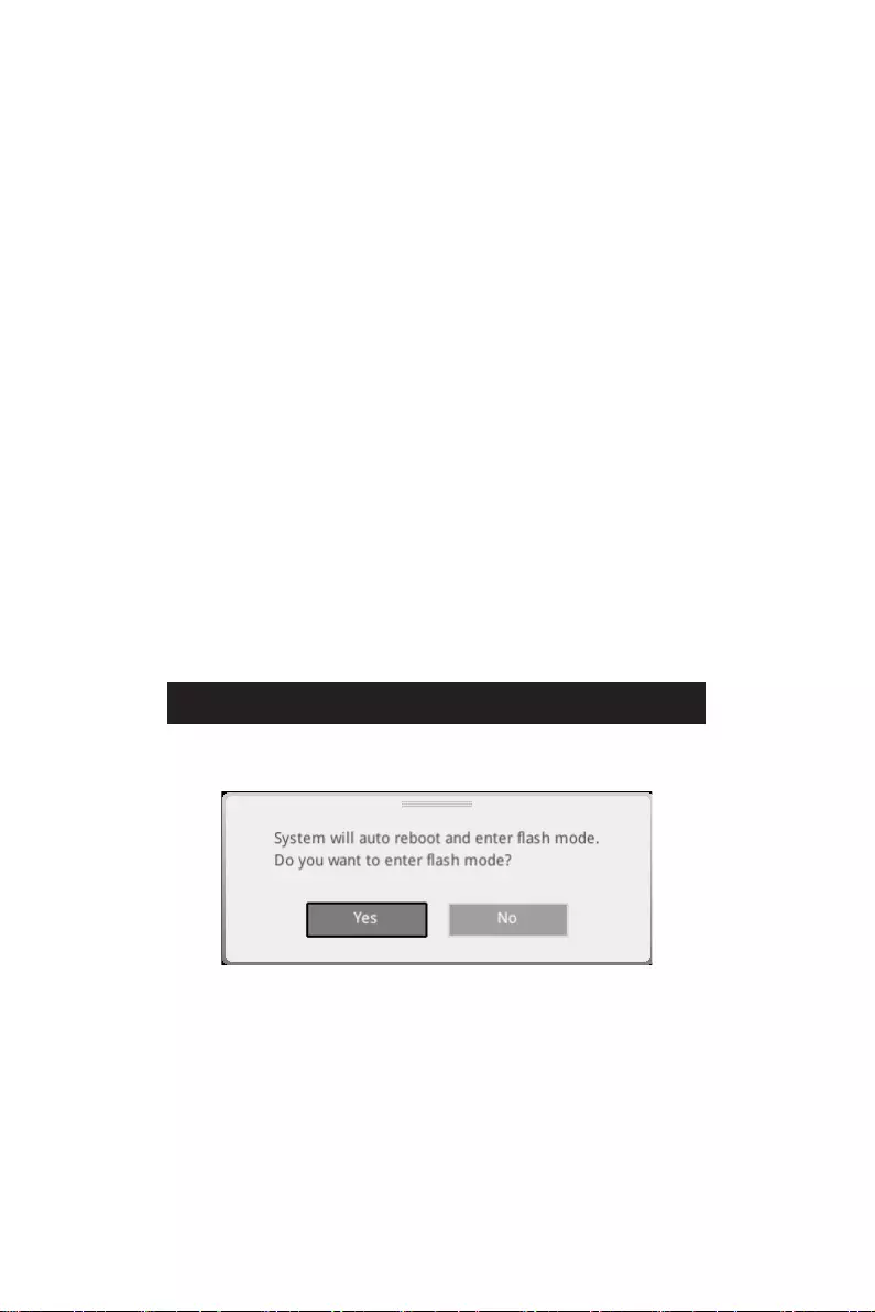
2. Please refer the following methods to enter flash mode.
▪Reboot and press Ctrl + F5 key during POST and click on Yes to reboot the
system.
Press <Ctrl+F5> to activate M-Flash for BIOS update.
▪Reboot and press Del key during POST to enter BIOS. Click the M-FLASH button
and click on Yes to reboot the system.
3. Select a BIOS file to perform the BIOS update process.
4. When prompted click on Yes to start recovering BIOS.
5. After the flashing process is 100% completed, the system will reboot
automatically.

56 UEFI BIOS
Updating the BIOS with MSI Center
Before updating:
∙Make sure the LAN driver is already installed and the internet connection is set
properly.
∙Please close all other application software before updating the BIOS.
To update BIOS:
1. Install and launch MSI CENTER and go to Support page.
2. Select Live Update and click on the Advanced button.
3. Select the BIOS file and click on the Install button.
4. The installation reminder will appear, then click the Install button on it.
5. The system will automatically restart to update BIOS.
6. After the flashing BIOS process is 100% completed, the system will restart
automatically.
Updating BIOS with Flash BIOS Button
1. Please download the latest BIOS file that matches your motherboard model from
the MSI® website.
2. Rename the BIOS file to MSI.ROM, and save it to the root of your USB flash drive.
3. Connect the power supply to CPU_PWR1 and ATX_PWR1. (No need to install CPU
and memory.)
4. Plug the USB flash drive that contains the MSI.ROM file into the Flash BIOS Port
on the rear I/O panel.
5. Press the Flash BIOS Button to flash BIOS, and the LED starts flashing.
6. The LED will be turned off when the process is completed.
RAID Configuration
The introduction of RAID levels and types are as below:
RAID 0 breaks the data into blocks which are written to separate hard drives.
Spreading the hard drive I/O load across independent channels greatly
improves I/O performance.
RAID 1 provides data redundancy by mirroring data between the hard drives and
provides enhanced read performance.
RAID 5 provides data striping at the byte level and also stripe error correction
information. This results in excellent performance and good fault tolerance.
RAID 10 uses four hard drives to create a combination of RAID 0 and 1 by forming a
RAID 0 array from two RAID 1 arrays.
RAID level comparison
RAID 0 RAID 1 RAID 5 RAID 10
Minimum # drives 2 2 3 4
Data protection None Excellent Excellent Excellent
Read performance Excellent OK Good OK
Write performance Excellent Good OK Good
Capacity utilization 100% 50% 67%~(1-1/n) 50%
⚠
Important
All the information/ volumes/ pictures listed in your system might differ from the
illustrations in this appendix.
Intel RAID User Guide
If you’d like to know more instructions on how to set up Intel RAID,
please refer to
http://download.msi.com/manual/mb/IntelRAID.pdf
or scan the QR code to access.
57
RAID Configuration
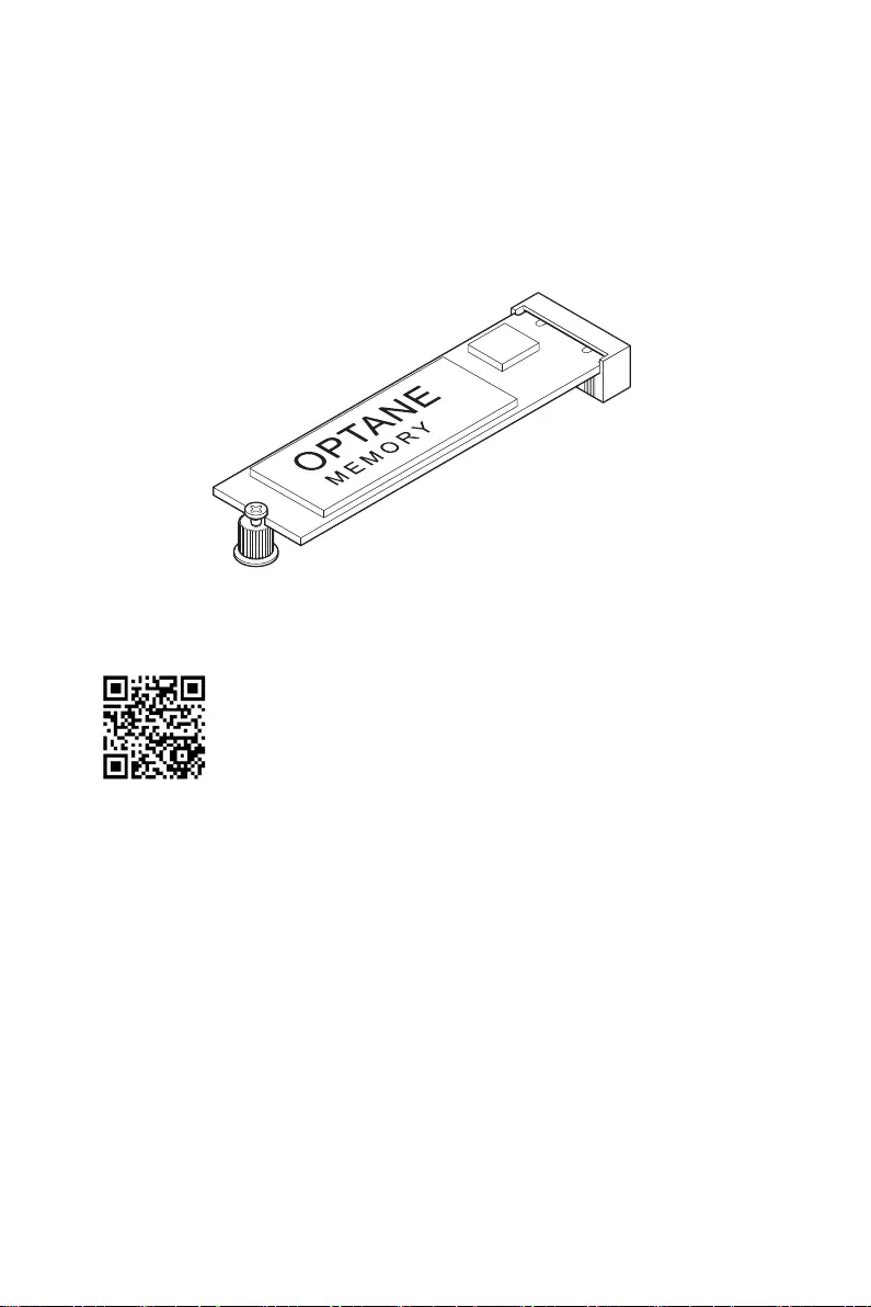
Intel® Optane™ Memory Configuration
Intel® Optane™ memory is a technology which allows the system to access the data
more quickly. It enables the computer to store commonly used data and programs,
and keeps them even after powering off the computer. Before you start to install Intel®
Optane™ memory, please note that it requires Windows 10 64-bit operating system.
Intel® Optane™ Memory User Guide
If you’d like to know more instructions on how to enable or remove
Intel® Optane™ Memory, please refer to
http://download.msi.com/manual/mb/Optane.pdf
or scan the QR code to access.
⚠
WARNING
After you enable Intel® Optane™ memory, please note the following to prevent damage
to your operating system.
∙
DO NOT set the SATA mode back to AHCI in BIOS.
∙
DO NOT revert back to older version of the BIOS.
∙
DO NOT remove the Intel® Optane™ memory module.
∙
DO NOT replace the CPU that is not supported by Intel® Optane™ Memory.
58 Intel® Optane™ Memory Configuration

Troubleshooting
Before sending the motherboard for RMA
repair, try to go over troubleshooting
guide first to see if your got similar
symptoms as mentioned below.
The power is not on.
∙Connect the AC power cord to an
electrical outlet securely.
∙Check if all ATX power connectors
like ATX_PWR1, CPU_PWR1 are
connected from the power supply to the
motherboard?
∙Some power supply units have a power
button on the rear side, make sure the
button is turned on.
∙Check if the power switch cable is
connected to JFP1 pin header properly.
∙Verify the Clear CMOS jumper JBAT1 is
set to Keep DATA.
∙Test with another known working
power supply of equal or greater
wattage.
The power is on, but no signal to
monitor
∙Connect the monitor power cord to a
electrical outlet securely.
∙Make sure the monitor is turned on.
∙Select different inputs on the monitor.
∙If 3 long beeps are heard, remove all
memory modules and try to install only
one memory module in the DIMMA2 slot
first and then restart the computer.
∙If 1 long 2 short beeps are heard,
remove and reinstall the graphics card
and then restart the computer.
∙Test with another known working
graphics card.
The computer does not boot after
updating the BIOS
∙Clear the CMOS.
∙Use the secondary BIOS to bootup the
system (Only for motherboard with Dual
BIOS)
Lost BIOS password
∙Clear the CMOS, but that will cause
you to lose all customized settings in the
BIOS.
There is no audio
∙Adjust the volume.
∙Connect the speakers/headphones to
audio ports on the motherboard rear IO
panel.
∙Remove secondary speakers/
headphones, HDMI cables, USB audio
devices.
∙Test with another known working
speaker or headphone.
There is no network
∙Make sure the network chipset driver
has been installed.
∙Verify if the network cable is properly
connected and make sure the LAN port
LEDs are properly illuminated.
∙Verify your TCP/IP settings.
∙Restart or reset your router.
∙Test with another known working LAN
cable.
The USB device is not working
∙Make sure your USB drive driver has
been installed.
∙Verify if USB device is listed in
Windows® Device Manager.
∙Connect the USB device to other USB
port on the motherboard rear IO panel.
59
Troubleshooting
i
Regulatory Notices
Regulatory Notices
FCC Compliance Statement
Note: This equipment has been tested and found to
comply with the limits for a Class B digital device,
pursuant to part 15 of the FCC Rules. These limits are
designed to provide reasonable protection against
harmful interference in a residential installation. This
equipment generates, uses and can radiate radio
frequency energy and, if not installed and used in
accordance with the instructions, may cause harmful
interference to radio communications. However, there
is no guarantee that interference will not occur in a
particular installation. If this equipment does cause
harmful interference to radio or television reception,
which can be determined by turning the equipment
off and on, the user is encouraged to try to correct the
interference by one or more of the following measures:
yReorient or relocate the receiving antenna.
yIncrease the separation between the equipment
and receiver.
yConnect the equipment into an outlet on a circuit
different from that to which the receiver is
connected.
yConsult the dealer or an experienced radio/TV
technician for help.
Caution: Changes or modifications not expressly
approved by the party responsible for compliance could
void the user’s authority to operate the equipment.
Tested to comply with FCC standards
FOR HOME OR OFFICE USE
This device complies with part 15 of the FCC Rules.
Operation is subject to the following two conditions:
(1) This device may not cause harmful interference,
and (2) this device must accept any interference
received, including interference that may cause
undesired operation.
CE Conformity
Products bearing the CE marking comply
with one or more of the following EU
Directives as may be applicable:
RED 2014/53/EU; Low Voltage Directive 2014/35/EU;
EMC Directive 2014/30/EU; RoHS Directive 2011/65/EU.
Compliance with these directives is assessed using
applicable European Harmonized Standards.
The point of contact for regulatory matters is MSI,
MSI-NL Eindhoven 5706 5692 ER Son.
KC인증서
yMPG Z590 GAMING CARBON WIFI
10-7D06
yMPG Z590 GAMING FORCE
20-7D06
クラスB情報技術装置
VCCI-B
C-Tick Compliance
Battery Information
European Union:
Batteries, battery packs, and
accumulators should not be disposed of as
unsorted household waste. Please use the
public collection system to return, recycle,
or treat them in compliance with the local
regulations.
Taiwan:
For better environmental protection,
waste batteries should be collected
separately for recycling or special
disposal.
California, USA:
The button cell battery may contain
perchlorate material and requires special
handling when recycled or disposed of in
California.
For further information please visit:
http://www.dtsc.ca.gov/hazardouswaste/perchlorate/
CAUTION: There is a risk of explosion, if battery is
incorrectly replaced.
Replace only with the same or equivalent type
recommended by the manufacturer.
Chemical Substances Information
In compliance with chemical substances regulations,
such as the EU REACH Regulation (Regulation EC
No. 1907/2006 of the European Parliament and the
Council), MSI provides the information of chemical
substances in products at:
https://storage-asset.msi.com/html/popup/csr/
evmtprtt_pcm.html
Environmental Policy
yThe product has been designed to
enable proper reuse of parts and
recycling and should not be thrown
away at its end of life.
yUsers should contact the local
authorized point of collection for recycling and
disposing of their end-of-life products.
yVisit the MSI website and locate a nearby distributor
for further recycling information.
yUsers may also reach us at gpcontdev@msi.com for
information regarding proper Disposal, Take-back,
Recycling, and Disassembly of MSI products.
WEEE (Waste Electrical and
R-R-MSI-10-7D06
R-R-MSI-20-7D06

ii Regulatory Notices
Electronic Equipment) Statement
ENGLISH
To protect the global environment and as
an environmentalist, MSI must remind
you that…
Under the European Union (“EU”)
Directive on Waste Electrical and
Electronic Equipment, Directive 2002/96/
EC, which takes effect on August 13,
2005, products of “electrical and electronic equipment”
cannot be discarded as municipal wastes anymore, and
manufacturers of covered electronic equipment will
be obligated to take back such products at the end of
their useful life. MSI will comply with the product take
back requirements at the end of life of MSI-branded
products that are sold into the EU. You can return
these products to local collection points.
DEUTSCH
Hinweis von MSI zur Erhaltung und Schutz unserer
Umwelt
Gemäß der Richtlinie 2002/96/EG über Elektro- und
Elektronik-Altgeräte dürfen Elektro- und Elektronik-
Altgeräte nicht mehr als kommunale Abfälle entsorgt
werden. MSI hat europaweit verschiedene Sammel-
und Recyclingunternehmen beauftragt, die in die
Europäische Union in Verkehr gebrachten Produkte,
am Ende seines Lebenszyklus zurückzunehmen.
Bitte entsorgen Sie dieses Produkt zum gegebenen
Zeitpunkt ausschliesslich an einer lokalen
Altgerätesammelstelle in Ihrer Nähe.
FRANÇAIS
En tant qu’écologiste et afin de protéger
l’environnement, MSI tient à rappeler ceci…
Au sujet de la directive européenne (EU) relative aux
déchets des équipement électriques et électroniques,
directive 2002/96/EC, prenant effet le 13 août 2005, que
les produits électriques et électroniques ne peuvent
être déposés dans les décharges ou tout simplement
mis à la poubelle. Les fabricants de ces équipements
seront obligés de récupérer certains produits en fin
de vie. MSI prendra en compte cette exigence relative
au retour des produits en fin de vie au sein de la
communauté européenne. Par conséquent vous pouvez
retourner localement ces matériels dans les points
de collecte.
РУССКИЙ
ESPAÑOL
MSI como empresa comprometida con la protección
del medio ambiente, recomienda:
Bajo la directiva 2002/96/EC de la Unión Europea
en materia de desechos y/o equipos electrónicos,
con fecha de rigor desde el 13 de agosto de 2005,
los productos clasificados como “eléctricos y
equipos electrónicos” no pueden ser depositados
en los contenedores habituales de su municipio, los
fabricantes de equipos electrónicos, están obligados
a hacerse cargo de dichos productos al termino de
su período de vida. MSI estará comprometido con los
términos de recogida de sus productos vendidos en
la Unión Europea al final de su periodo de vida. Usted
debe depositar estos productos en el punto limpio
establecido por el ayuntamiento de su localidad o
entregar a una empresa autorizada para la recogida de
estos residuos.
NEDERLANDS
Om het milieu te beschermen, wil MSI u eraan
herinneren dat….
De richtlijn van de Europese Unie (EU) met betrekking
tot Vervuiling van Electrische en Electronische
producten (2002/96/EC), die op 13 Augustus 2005 in
zal gaan kunnen niet meer beschouwd worden als
vervuiling. Fabrikanten van dit soort producten worden
verplicht om producten retour te nemen aan het
eind van hun levenscyclus. MSI zal overeenkomstig
de richtlijn handelen voor de producten die de
merknaam MSI dragen en verkocht zijn in de EU. Deze
goederen kunnen geretourneerd worden op lokale
inzamelingspunten.
SRPSKI
vas podesti da…
EC, koja stupa na snagu od 13. Avgusta 2005, proizvodi
proizvoda kojima je istekao vek trajanja, koji imaju MSI
vratiti na lokalnim mestima za prikupljanje.
POLSKI
odpadów produktów elektrycznych i elektronicznych
(sprzedawane na terenie Unii Europejskiej) wycofywane
wyznaczonych punktach zbiorczych.
TÜRKÇE

iii
Regulatory Notices
ČESKY
EC platné od 13. srpna 2005 je zakázáno likvidovat
komunálním odpadu a výrobci elektronických
MAGYAR
Annak érdekében, hogy környezetünket megvédjük,
Önt, hogy …
Az Európai Unió („EU”) 2005. augusztus 13-án hatályba
hulladékairól szóló 2002/96/EK irányelve szerint
az elektromos és elektronikus berendezések
és az ilyen elektronikus berendezések gyártói
kötelessé válnak az ilyen termékek visszavételére
azok hasznos élettartama végén. Az MSI betartja a
termékvisszavétellel kapcsolatos követelményeket
az MSI márkanév alatt az EU-n belül értékesített
termékek esetében, azok élettartamának végén. Az
ITALIANO
Per proteggere l’ambiente, MSI, da sempre amica della
natura, ti ricorda che….
In base alla Direttiva dell’Unione Europea (EU) sullo
Smaltimento dei Materiali Elettrici ed Elettronici,
Direttiva 2002/96/EC in vigore dal 13 Agosto 2005,
prodotti appartenenti alla categoria dei Materiali
Elettrici ed Elettronici non possono più essere eliminati
come rifiuti municipali: i produttori di detti materiali
saranno obbligati a ritirare ogni prodotto alla fine
del suo ciclo di vita. MSI si adeguerà a tale Direttiva
ritirando tutti i prodotti marchiati MSI che sono stati
venduti all’interno dell’Unione Europea alla fine del
loro ciclo di vita. È possibile portare i prodotti nel più
vicino punto di raccolta
日本JIS C 0950材質宣言
https://storage-asset.msi.com/html/popup/csr/
cemm_jp.html
India RoHS
This product complies with the “India E-waste
(Management and Handling) Rule 2011” and prohibits
use of lead, mercury, hexavalent chromium,
polybrominated biphenyls or polybrominated diphenyl
ethers in concentrations exceeding 0.1 weight % and
0.01 weight % for cadmium, except for the exemptions
set in Schedule 2 of the Rule.
Türkiye EEE yönetmeliği
Україна обмеження на наявність
небезпечних речовин
Việt Nam RoHS
Wireless Radio Use
This device is restricted to indoor use when operating
in the 2.4GHz, 5GHz frequency band.
Cet appareil doit être utilisé à l’intérieur.
NCC無線設備警告聲明
Products with radio functionality (EMF)
This product incorporates a radio transmitting
and receiving device. For computers in normal
use, a separation distance of 20 cm ensures that
radio frequency exposure levels comply with EU
requirements. Products designed to be operated
at closer proximities, such as tablet computers,
comply with applicable EU requirements in typical
operating positions. Products can be operated without
maintaining a separation distance unless otherwise
indicated in instructions specific to the product.
Restrictions for products with radio functionality
CAUTION: IEEE 802.11x wireless LAN with
5.15–5.35 GHz frequency band is restricted
for indoor use only in all European Union
member states, EFTA (Iceland, Norway,
Liechtenstein), and most other European
countries (e.g., Switzerland, Turkey, Republic of
Serbia). Using this WLAN application outdoors might
lead to interference issues with existing radio services.
Radio frequency bands and maximum power levels
Features :802.11 a/b/g/n/ac/ax, BT
Frequency Range :2.4GHz, 5GHz
Modulation :FHSS, DSSS, OFDM
Power Output :10, 20, 23
Channel Band Width :1, 5, 20 ,40 , 80, 160MHz
iv Regulatory Notices
MS-7D06主板产品中有害物质的名称及含量
(Pb)
(Hg)
(Cd)
(Cr(VI))
(PBB)
(PBDE)
限用物質含有情況標示聲明書
(Pb)
(Hg)
(Cd)
(Cr+6)
(PBB)
(PBDE)
Copyright
Micro-Star Int’l Co.,Ltd.
Copyright © 2020 All rights reserved.
The MSI logo used is a registered trademark of
Micro-Star Int’l Co., Ltd. All other marks and names
mentioned may be trademarks of their respective
owners. No warranty as to accuracy or completeness is
expressed or implied. MSI reserves the right to make
changes to this document without prior notice.
Revision History
Version 1.0, 2020/12, First release.
Technical Support
If a problem arises with your system and no solution
can be obtained from the user guide, please
contact your place of purchase or local distributor.
Alternatively, please try the following help resources
for further guidance.
yVisit the MSI website for technical guide, BIOS
updates, driver updates, and other information:
http://www.msi.com
yRegister your product at: http://register.msi.com
View the manual for the MSI MPG Z590 Gaming Carbon WIFI here, for free. This user manual comes under the category motherboards and has been rated by 1 people with an average of a 8.1. This manual is available in the following languages: English. Do you have a question about the MSI MPG Z590 Gaming Carbon WIFI?
Ask your question here
MSI MPG Z590 Gaming Carbon WIFI specifications
Below you will find the product specifications and the manual specifications of the MSI MPG Z590 Gaming Carbon WIFI.
Processor manufacturer
Intel
Motherboard chipset family
Intel
Supported memory types
DDR4-SDRAM
PCI Express x1 (Gen 3.x) slots
2
Parallel processing technology support
3-Way CrossFireX
General
| Brand | MSI |
| Model | MPG Z590 Gaming Carbon WIFI | MPG Z590 GAMING CARBON WIFI |
| Product | motherboard |
| EAN | 0824142242155, 4719072800505, 824142242155 |
| Language | English |
| Filetype | User manual (PDF) |
Processor
| Processor manufacturer | Intel |
| Processor socket | LGA 1200 (Socket H5) |
| Compatible processor series | Intel Celeron, Intel Core i3, Intel Core i5, Intel Core i7, Intel Core i9, Intel Pentium |
Features
| Motherboard chipset family | Intel |
| Motherboard chipset | Intel Z590 |
| Audio output channels | 7.1 channels |
| Audio chip | Realtek ALC4080 |
| Component for | PC |
| Motherboard form factor | ATX |
| Windows operating systems supported | Windows 10 x64 |
Memory
| Supported memory types | DDR4-SDRAM |
| Number of memory slots | 4 |
| Memory slots type | DIMM |
| Memory channels | Dual-channel |
| Unbuffered memory | Yes |
| Maximum internal memory | 128 GB |
| Supported memory clock speeds | 2133,2400,2666,2933,3000,3200,3300,3333,3400,3466,3600,3733,3866,4000,4133,4200,4266,4300,4400,4533,4600,4800,5000,5200,5333 MHz |
Expansion slots
| PCI Express x1 (Gen 3.x) slots | 2 |
| PCI Express x16 slots | 3 |
| Number of M.2 (M) slots | 3 |
Graphics
| Parallel processing technology support | 3-Way CrossFireX |
| Maximum resolution | 4096 x 2160 pixels |
| DirectX version | 12.0 |
Storage controllers
| RAID levels | 0, 1,5, 10 |
| Supported storage drive interfaces | M.2, SATA III |
| Supported storage drive types | HDD & SSD |
| RAID support | Yes |
Network
| Ethernet LAN | Yes |
| Ethernet interface type | 2.5 Gigabit Ethernet |
| Wi-Fi | Yes |
| LAN controller | Intel I225-V |
| Top Wi-Fi standard | Wi-Fi 6 (802.11ax) |
| WLAN controller model | Intel Wi-Fi 6E AX210 |
| Wi-Fi standards | 802.11a, 802.11b, 802.11g, Wi-Fi 4 (802.11n), Wi-Fi 6 (802.11ax) |
| Bluetooth | Yes |
| Bluetooth version | 5.2 |
Internal I/O
| ATX Power connector (24-pin) | Yes |
| 12V power connector | Yes |
| Number of SATA III connectors | 6 |
| Number of SATA II connectors | 0 |
| USB 3.2 Gen 2 (3.1 Gen 2) connectors | 1 |
| USB 3.2 Gen 1 (3.1 Gen 1) connectors | 1 |
| USB 2.0 connectors | 2 |
| CPU fan connector | Yes |
| Number of chassis fan connectors | 6 |
| Front panel audio connector | Yes |
| Front panel connector | Yes |
| Chassis intrusion connector | Yes |
| TPM connector | Yes |
| Number of Parallel ATA connectors | 0 |
| EPS power connector (8-pin) | Yes |
BIOS
| Clear CMOS jumper | Yes |
| BIOS type | UEFI AMI |
Rear panel I/O ports
| USB 2.0 ports quantity | 4 |
| DisplayPorts quantity | 1 |
| USB 3.2 Gen 1 (3.1 Gen 1) Type-A ports quantity | 2 |
| USB 3.2 Gen 1 (3.1 Gen 1) Type-C ports quantity | 0 |
| Ethernet LAN (RJ-45) ports | 1 |
| Headphone outputs | 1 |
| Microphone in | Yes |
| S/PDIF out port | Yes |
| HDMI ports quantity | 1 |
| USB 3.2 Gen 2 (3.1 Gen 2) Type-A ports quantity | 2 |
| USB 3.2 Gen 2 (3.1 Gen 2) Type-C ports quantity | 0 |
| eSATA ports quantity | 0 |
| PS/2 ports quantity | 0 |
| Firewire (IEEE 1394) ports | 0 |
| VGA (D-Sub) ports quantity | 0 |
| DVI-D ports quantity | 0 |
| WiFi-AP antenna jack | 2 |
| USB 3.2 Gen 2×2 Type-C ports quantity | 1 |
| HDMI version | 2.0b |
| DisplayPort version | 1.4 |
Weight & dimensions
Logistics data
| Harmonized System (HS) code | 84733020 |
show more
Frequently asked questions
Can’t find the answer to your question in the manual? You may find the answer to your question in the FAQs about the MSI MPG Z590 Gaming Carbon WIFI below.
What is the width of the MSI MPG Z590 Gaming Carbon WIFI?
The MSI MPG Z590 Gaming Carbon WIFI has a width of 305 mm.
What is the depth of the MSI MPG Z590 Gaming Carbon WIFI?
The MSI MPG Z590 Gaming Carbon WIFI has a depth of 244 mm.
Is the manual of the MSI MPG Z590 Gaming Carbon WIFI available in English?
Yes, the manual of the MSI MPG Z590 Gaming Carbon WIFI is available in English .
Is your question not listed? Ask your question here
FAQ: Types of Manuals and Their Contents
MSI MPG Z590 GAMING CARBON WIFI Manuals come in various types, each serving a specific purpose to help users effectively operate and maintain their devices. Here are the common types of MSI MPG Z590 GAMING CARBON WIFI User Guides and the information they typically include:
- User Manuals: Provide comprehensive instructions on how to use the device, including setup, features, and operation. They often include troubleshooting tips, safety information, and maintenance guidelines.
- Service Instructions: Designed for technicians and repair professionals, these manuals offer detailed information on diagnosing and repairing issues with the device. They include schematics, parts lists, and step-by-step repair procedures.
- Installation Guides: Focus on the installation process of the device, providing detailed instructions and diagrams for proper setup. They are essential for ensuring the device is installed correctly and safely.
- Maintenance Manuals: Provide guidance on routine maintenance tasks to keep the device in optimal condition. They cover cleaning procedures, part replacements, and regular servicing tips.
- Quick Start Guides: Offer a concise overview of the essential steps needed to get the device up and running quickly. They are ideal for users who need immediate assistance with basic setup and operation.
Each type of MSI MPG Z590 GAMING CARBON WIFI instruction is designed to address specific needs, ensuring users have the necessary information to use, maintain, and repair their devices effectively.
Related Instructions for MSI MPG Z590 GAMING CARBON WIFI:
2
Z77A-GD55
Instruction manual MSI Motherboard Instruction manual (File: msi-z77a-gd55-instruction-manual-210, 16/09/2024)
210
1004
151
3
Mega Player 522
54
587
130
4
H170A GAMING PRO
148
1066
203
7
Pro266 Master
Manual #O2132P: Pro266 Master Motherboard Manual
102
918
157
10
Optix Series
Manual MSI Optix Series Guide (Manual ), @FQN8FF
34
1115
279
Motherboard Devices by Other Brands:
|
Texas Instruments CC1111 Quick Start Manual PDF User Manual (@89K374), Texas Instruments CC1111 Motherboard (Thu 01.2025) SWRU328 16 Jan 2025 | 6 |
|
|
mikroElektronika Joystick click Manual mikroElektronika Motherboard Manual (File: mikroelektronika-joystick-click-manual-2, 23/03/2025) 1. Introduction 23 Mar 2025 | 2 |
|
|
ASROCK Z490 Extreme4 Manual PDF Guide (@N68I11), ASROCK Z490 Extreme4 Motherboard (Friday 04-04-2025) Version 1.1 04 Apr 2025 | 190 |
|
|
ASROCK P55 EXTREME Installation Manual #7VAD55: P55 EXTREME Motherboard Installation manual 11111 06 Mar 2025 | 226 |
Categories:
Pc
All-in-one pc
Medical Equipment
Kitchen Appliances
Pcs
Mainboard
MSI MPG Z590 GAMING CARBON WIFI Motherboard PDF User Guides and Manuals for Free Download: Found (3) Manuals for MSI MPG Z590 GAMING CARBON WIFI Device Model (Quick Start Manual)
The MSI MPG Z590 GAMING CARBON WIFI is a high-performance motherboard that primarily targets gamers and computer enthusiasts who demand reliability and advanced features. With its sleek design and robust power delivery system, this motherboard stands out in the crowded field of gaming hardware. MSI has a solid reputation for producing quality motherboards, and this model lives up to that expectation while incorporating modern technologies that cater to the latest Intel processors.
One of the standout features of the MPG Z590 GAMING CARBON WIFI is its support for Intel’s 11th and 10th generation processors. This compatibility allows users to maximize their gaming performance by harnessing the full potential of the latest CPUs. Moreover, the motherboard utilizes the LGA 1200 socket, ensuring seamless installation and upgrade options for different processors. This feature is essential for gamers who want to future-proof their systems.
Another highlight of the MSI MPG Z590 GAMING CARBON WIFI is its power delivery system. This motherboard is equipped with a 14+1+1 digital power design, providing sufficient power for overclocking and demanding tasks. The ability to push components to their limits is crucial for serious gamers looking to get the most out of their hardware. Additionally, the motherboard comes with enhanced thermal solutions, including large heatsinks and dedicated heat pipes, which help maintain optimal temperatures during intense gaming sessions.
The MPG Z590 GAMING CARBON WIFI also shines in the connectivity department. It features multiple USB 3.2 Gen 2 ports, ensuring lightning-fast data transfer speeds. Furthermore, the integrated Wi-Fi 6 capability allows for smoother online gaming experiences, reducing latency and increasing connection stability. Other connectivity options include Bluetooth 5.2, allowing for wireless peripherals usage without compromising performance.
In terms of visual aesthetics, the MSI MPG Z590 GAMING CARBON WIFI does not disappoint. The motherboard boasts an elegant black and silver design, enhanced by RGB lighting options that can be customized through the MSI Mystic Light software. Gamers can easily synchronize their lighting effects with other compatible components, creating a cohesive build that looks as good as it performs.
Moreover, the packaging includes key features such as:
- Support for high-speed DDR4 memory up to 5333 MHz (OC)
- PCIe 4.0 support, enhancing GPU performance
- Four M.2 slots for ultra-fast NVMe SSDs
- High-quality audio components providing immersive sound experiences
While the MSI MPG Z590 GAMING CARBON WIFI impresses with its feature set, it is worth noting that its price point is on the higher end of the spectrum. However, for serious gamers and PC builders, the investment pays off with superior performance and longevity. The BIOS is user-friendly, making it easier for even novice builders to navigate through settings and configurations effectively.
In conclusion, the MSI MPG Z590 GAMING CARBON WIFI caters well to users seeking a feature-rich and aesthetically pleasing motherboard. Its performance capability combined with advanced features makes it a strong contender in the marketplace. If you are a gamer looking to build a high-performance PC, the MPG Z590 GAMING CARBON WIFI is undoubtedly a worthwhile consideration.