

I
MPG Z690 EDGE WIFI
Motherboard
User Guide
Benutzerhandbuch
Manuel d’utilisation

II
English
Deutsch
Français

III
Quick Start
Thank you for purchasing the MSI® motherboard. This Quick Start section provides
demonstration diagrams about how to install your computer. Some of the installations
also provide video demonstrations. Please link to the URL to watch it with the web
browser on your phone or tablet. You may have even link to the URL by scanning the
QR code.
Kurzanleitung
Danke, dass Sie das MSI® Motherboard gewählt haben. Dieser Abschnitt der
Kurzanleitung bietet eine Demo zur Installation Ihres Computers. Manche
Installationen bieten auch die Videodemonstrationen. Klicken Sie auf die URL, um
diese Videoanleitung mit Ihrem Browser auf Ihrem Handy oder Table anzusehen. Oder
scannen Sie auch den QR Code mit Ihrem Handy, um die URL zu öffnen.
Présentation rapide
Merci d’avoir choisi la carte mère MSI®. Ce manuel fournit une rapide présentation
avec des illustrations explicatives qui vous aideront à assembler votre ordinateur.
Des tutoriels vidéo sont disponibles pour certaines étapes. Cliquez sur le lien fourni
pour regarder la vidéo sur votre téléphone ou votre tablette. Vous pouvez également
accéder au lien en scannant le QR code qui lui est associé.
IV
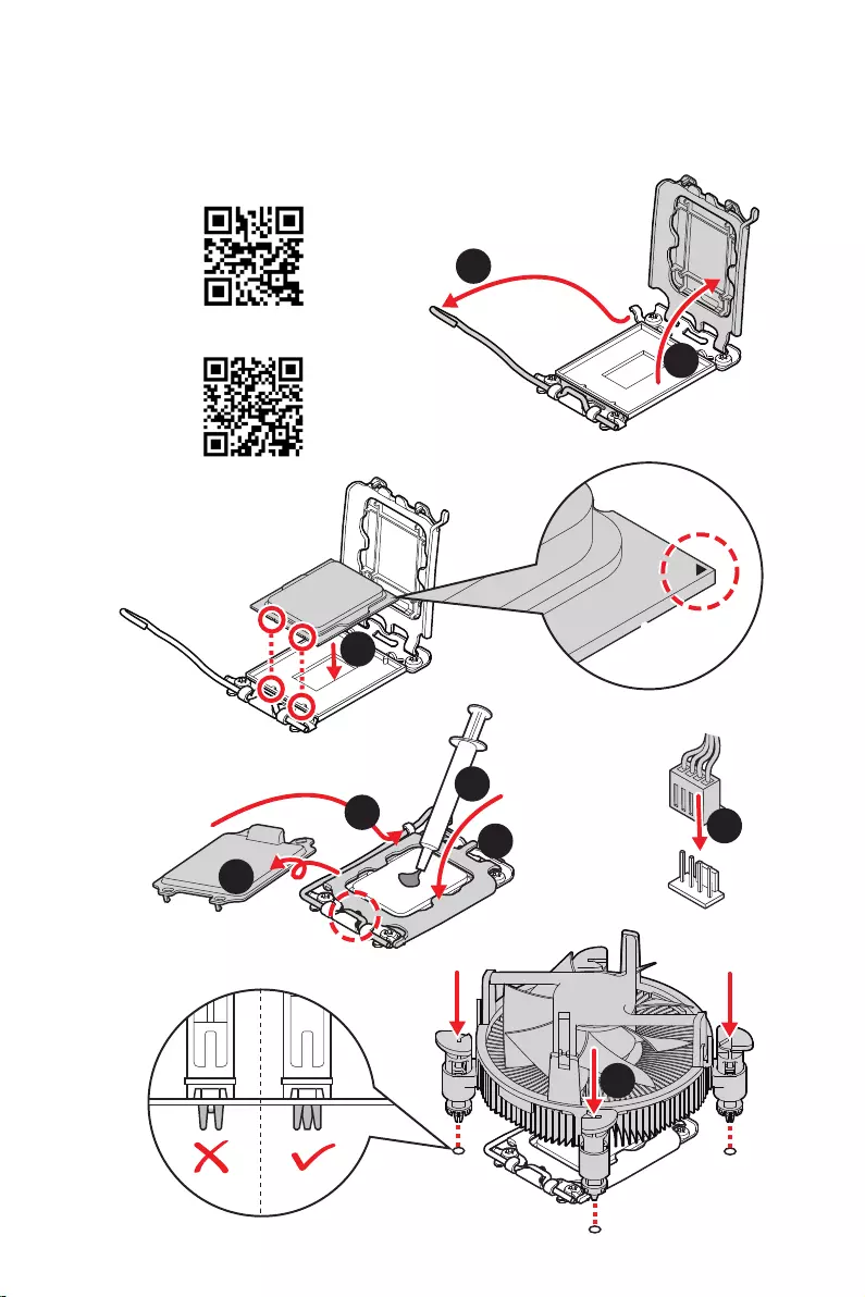
Installing a Processor/ Installation des Prozessors/ Installer un
https://v.youku.com/v_show/id_
XNTE5NDQwNDY2NA==.html
Youtube
1
2
3
6
4
5
7
8
9
V
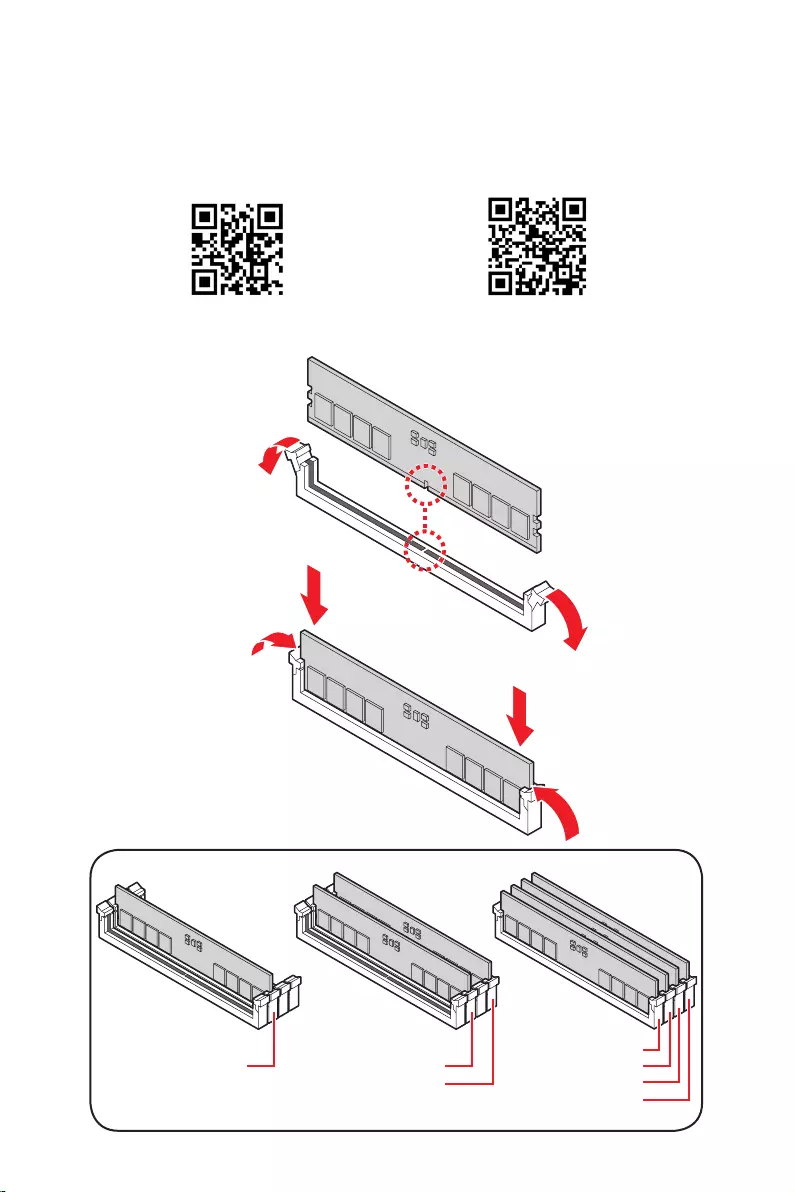
Installing DDR5 memory/ Installation des DDR5-Speichers/
DIMMA2 DIMMA2
DIMMB2
DIMMA1
DIMMA2
DIMMB1
DIMMB2
Youtube
https://v.youku.com/v_show/id_
XNTE5NTg0NDM4NA==.html
VI
HDD LED
RESET SW
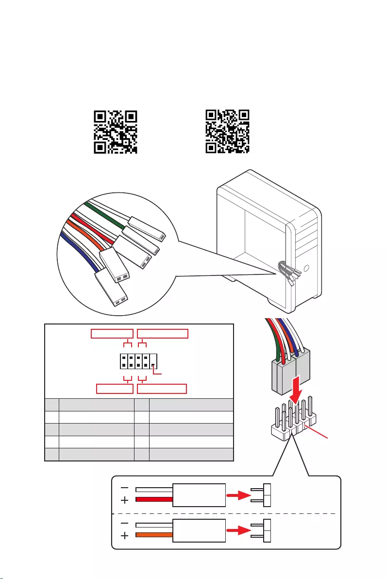
JFP1
HDD LED
HDD LED +
POWER LED +
POWER LED
1
2 10
9
+
+
+
+
Power LED
HDD LED Reset Switch
Reserved
Power Switch
JFP1
1 HDD LED + 2 Power LED +
3 4
5 Reset Switch 6 Power Switch
7 Reset Switch 8 Power Switch
9 Reserved 10 No Pin
RESET SW
POWER SW
POWER LED+
POWER LED-
HDD LED
Youtube
http://v.youku.com/v_show/id_XNjcyMTczMzM2.html
VII
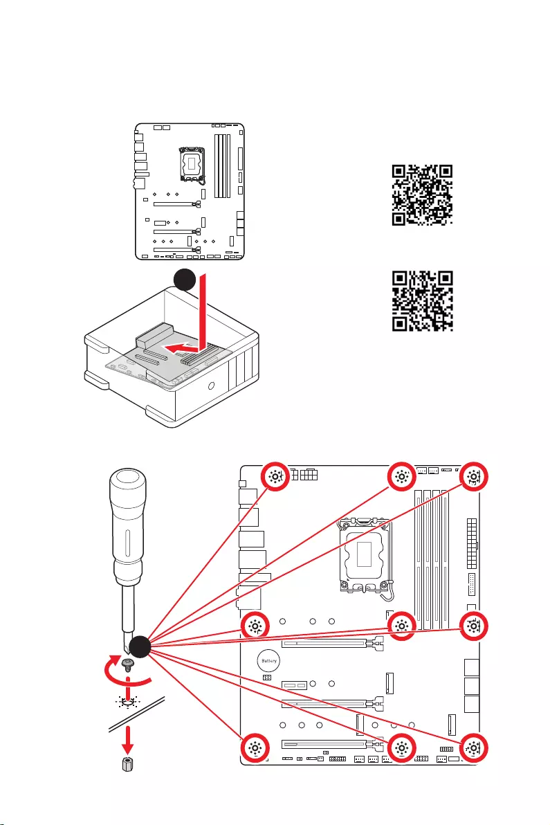
Installing the Motherboard/ Installation des Motherboards/
https://v.youku.com/v_show/id_
XNDUwMDUyNTkwOA==.html
Youtube
1
2
Torque:
3 kgf·cm*
*3 kgf·cm
= 0.3 N·m
= 2.6 lbf·in
VIII
http://youtu.be/gkDYyR_83I4 http://v.youku.com/v_show/id_XNDkzODU0MDQw.html
Youtube
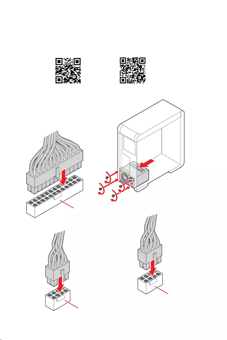
ATX_PWR1
CPU_PWR1
CPU_PWR2
IX
http://v.youku.com/v_show/
id_XNDkzODU5MTky.html
Youtube
1
23
4
5
X
http://v.youku.com/v_show/
id_XNDkyOTc3MzQ4.html
Youtube
1
2
3
4
5
6
XI
XII
4
3
12

1
Safety Information ……………………………………………………………………………………. 3
…………………………………………………………………………. 4
Avoid collision notification ………………………………………………………………………….. 4
Specifications …………………………………………………………………………………………… 5
Package contents …………………………………………………………………………………… 12
……………………………………………………………………………………….. 13
LAN Port LED Status Table ………………………………………………………………………. 13
Audio Ports Configuration ………………………………………………………………………… 13
Realtek Audio Console …………………………………………………………………………….. 14
………………………………………………………………………… 17
CPU Socket …………………………………………………………………………………………….. 18
DIMM Slots ……………………………………………………………………………………………… 19
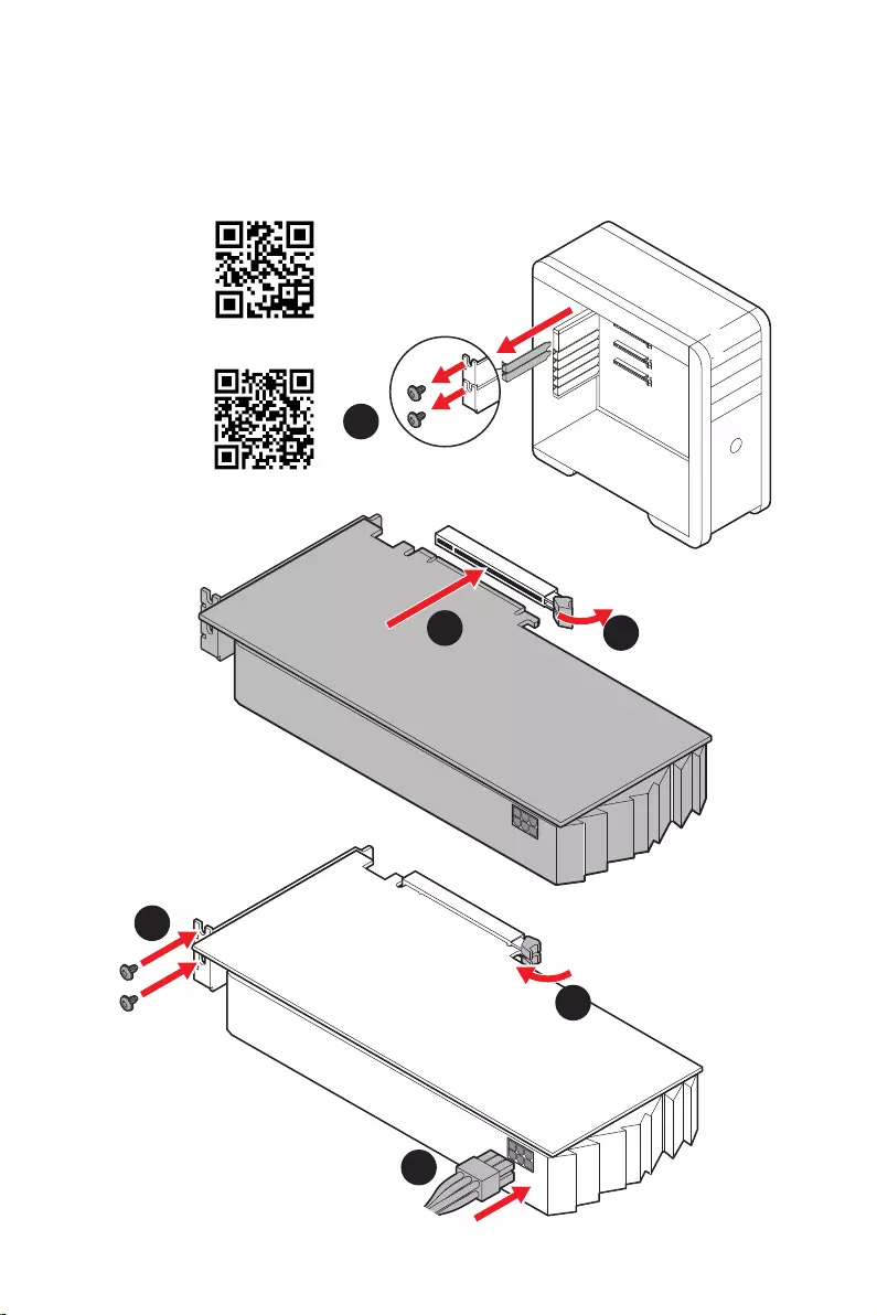
PCI_E1~4: PCIe Expansion Slots ……………………………………………………………….. 20
……………………………………………… 20
M2_1~4: M.2 Slots (Key M) ……………………………………………………………………….. 21
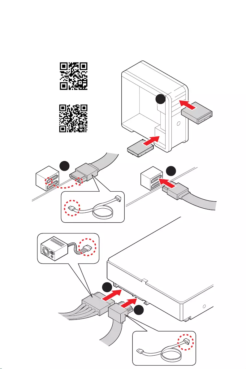
SATA5~8 & SATAA~B: SATA 6Gb/s Connectors …………………………………………… 23
JAUD1: Front Audio Connector …………………………………………………………………. 23
JFP1, JFP2: Front Panel Connectors …………………………………………………………. 24
CPU_PWR1~2, ATX_PWR1: Power Connectors …………………………………………… 25
…………………………………………………… 26
JUSB3: USB 3.2 Gen 1 Connector ……………………………………………………………… 26
JUSB1~2: USB 2.0 Connectors ………………………………………………………………….. 27
JTPM1: TPM Module Connector ………………………………………………………………… 27
CPU_FAN1, PUMP_FAN1, SYS_FAN1~6: Fan Connectors ……………………………. 28
JCI1: Chassis Intrusion Connector …………………………………………………………….. 29
JBAT1: Clear CMOS (Reset BIOS) Jumper ………………………………………………….. 30
JDASH1 : Tuning Controller connector ………………………………………………………. 30
JRGB1: RGB LED connector ……………………………………………………………………… 31
JRAINBOW1~3: Addressable RGB LED connectors …………………………………….. 32
………………………………………………………………………………………… 33
EZ Debug LED …………………………………………………………………………………………. 33
LED_SW1: EZ LED Control ……………………………………………………………………….. 33
JPWRLED1: LED power input ……………………………………………………………………. 33
………………………………………………………….. 34
Installing Windows 10/ Windows 11 …………………………………………………………… 34
English

2
Installing Drivers …………………………………………………………………………………….. 34
MSI Center ……………………………………………………………………………………………… 34
………………………………………………………………………………………………. 35
BIOS Setup ……………………………………………………………………………………………… 36
Entering BIOS Setup ………………………………………………………………………………… 36
BIOS User Guide ……………………………………………………………………………………… 36
Resetting BIOS ………………………………………………………………………………………… 37
Updating BIOS …………………………………………………………………………………………. 37

3
Safety Information
Safety Information
The components included in this package are prone to damage from electrostatic
discharge (ESD). Please adhere to the following instructions to ensure successful
computer assembly.
Ensure that all components are securely connected. Loose connections may cause
the computer to not recognize a component or fail to start.
Hold the motherboard by the edges to avoid touching sensitive components.
It is recommended to wear an electrostatic discharge (ESD) wrist strap when
handling the motherboard to prevent electrostatic damage. If an ESD wrist strap is
not available, discharge yourself of static electricity by touching another metal object
before handling the motherboard.
pad whenever the motherboard is not installed.
Before turning on the computer, ensure that there are no loose screws or metal
components on the motherboard or anywhere within the computer case.
Do not boot the computer before installation is completed. This could cause
permanent damage to the components as well as injury to the user.
If you need help during any installation step, please consult a certified computer
technician.
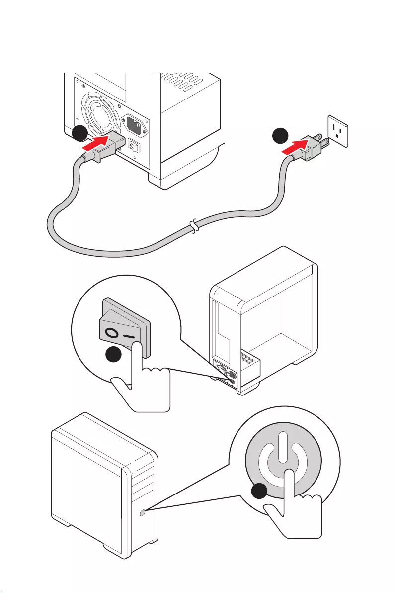
Always turn off the power supply and unplug the power cord from the power outlet
before installing or removing any computer component.
Keep this user guide for future reference.
Keep this motherboard away from humidity.
Make sure that your electrical outlet provides the same voltage as is indicated on
the PSU, before connecting the PSU to the electrical outlet.
Place the power cord such a way that people can not step on it. Do not place
anything over the power cord.
All cautions and warnings on the motherboard should be noted.
If any of the following situations arises, get the motherboard checked by service
personnel:
Liquid has penetrated into the computer.
The motherboard has been exposed to moisture.
The motherboard does not work well or you can not get it work according to user
guide.
The motherboard has been dropped and damaged.
The motherboard has obvious sign of breakage.
Do not leave this motherboard in an environment above 60°C (140°F), it may damage
the motherboard.
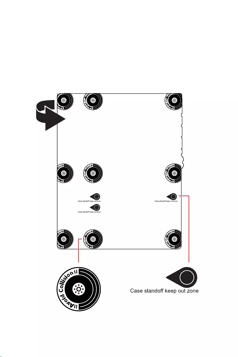
4Safety Information
the motherboard circuits and the computer case is prohibited. The Case standoff keep
out zone signs will be marked on the backside of motherboard (as shown below) to
serve as a warning to user.
Protective paint is printed around each screw hole to prevent parts from being
scratched.

5
Specifications
Specifications
Supports 12th Gen Intel® Core™, Pentium® Gold and
Celeron® Processors*
Processor socket LGA1700
* Please go to www.msi.com to get the newest support status as new processors
are released.
Intel® Z690 Chipset
Memory
4x DDR5 memory slots, support up to 128GB*
Supports JEDEC standard DDR5 4800/ 6666 (OC) MHz
Supports Intel® XMP 3.0 OC
*Please refer to www.msi.com for more information on compatible memory.
Expansion Slot
3x PCIe x16 slots
PCI_E1 slot (From CPU)
Supports PCIe 5.0 x16
PCI_E3 & PCI_E4 slots (From Z690 chipset)
Supports PCIe 3.0 x4
1x PCIe 3.0 x1 slot (From Z690 chipset)
Supports AMD® CrossFire™ Technology
1x HDMI 2.1 with HDR port, supports a maximum
resolution of 4K 60Hz*/**
1x DisplayPort 1.4 port with HBR3, supports a maximum
resolution of 4K 60Hz*/**
*Available only on processors featuring integrated graphics.
** Graphics specifications may vary depending on the Processor installed.
Continued on next page

6Specifications
Continued from previous page
Storage
6x SATA 6Gb/s ports
SATA5~8 (From Z690 Chipset)
SATAA~B (From ASMedia ASM1061)
4x M.2 slots (Key M)
M2_1 slot (From CPU)
Supports PCIe 4.0 x4
Supports 2260/ 2280/ 22110 storage devices
M2_2 slot (From Z690 Chipset)
Supports PCIe 4.0 x4
Supports 2260/ 2280 storage devices
M2_3 slot (From Z690 Chipset)
Supports PCIe 4.0 x4
Supports SATA 6Gb/s
Supports 2242/ 2260/ 2280 storage devices
M2_4 slot (From Z690 Chipset)
Supports PCIe 4.0 x4
Supports SATA 6Gb/s
Supports 2242/ 2260/ 2280 storage devices
M2_2~4 support Intel® Optane™ Memory
Supports Intel® Smart Response Technology for Intel
Core™ processors
Supports RAID 0, RAID 1, RAID 5 and RAID 10 for SATA
storage devices*
Supports RAID 0, RAID 1 and RAID 5 for M.2 PCIe storage
devices
* SATAA & SATAB do not support RAID function.
Realtek® ALC4080
Supports S/PDIF output
Continued on next page

7
Specifications
Continued from previous page
Intel® Z690 Chipset
panel
2x USB 3.2 Gen 1 5Gbps ports available through the
internal USB connector
4x USB 2.0 ports available through the internal USB
connectors
1x Intel® I225V 2.5Gbps LAN controller
slot
(160MHz) up to 2.4Gbps
Supports 802.11 a/ b/ g/ n/ ac/ ax
Supports Bluetooth® 5.2**, FIPS, FISMA
Windows 10 version 21H1 and Windows 11.
** Bluetooth 5.2 will be ready in Windows 10 version 21H1 and Windows 11.
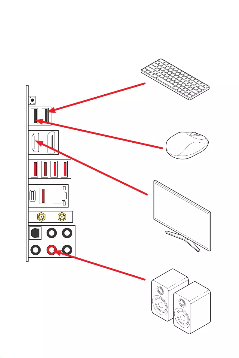
1x Flash BIOS button
2x USB 2.0 ports
1x DisplayPort
1x HDMI port
1x 2.5Gbps LAN (RJ45) port
5x audio jacks
1x Optical S/PDIF Out connector
Continued on next page

8Specifications
Continued from previous page
6x SATA 6Gb/s connectors
1x USB 3.2 Gen 1 5Gbps connector (supports additional 2
USB 3.2 Gen 1 5Gbps ports)
2x USB 2.0 connectors (supports additional 4 USB 2.0
ports)
1x Front panel audio connector
2x System panel connectors
1x Chassis Intrusion connector
1xTPM module connector
1x Clear CMOS jumper
1x Tuning controller connector
1x TBT connector (Supports RTD3)
1x EZ LED Control switch
4x EZ Debug LED
NUVOTON NCT6687D Controller Chip
CPU/ System/ Chipset temperature detection
CPU/ System/ Pump fan speed detection
CPU/ System/ Pump fan speed control
Form Factor ATX Form Factor
12 in. x 9.6 in. (30.5 cm x 24.4 cm)
Continued on next page

9
Specifications
Continued from previous page
1x 256 Mb flash
UEFI AMI BIOS
ACPI 6.4, SMBIOS 3.4
Drivers
MSI Center
Intel® Extreme Tuning Utility
MSI APP Player (BlueStacks)
Open Broadcaster Software (OBS)
Google Chrome™, Google Toolbar, Google Drive
Norton™ Internet Security Solution
Features
Gaming Mode
Smart Priority
Gaming Highlight
LAN Manager
Mystic Light
Ambient Devices
Frozr AI Cooling
User Scenario
True Color
Live Update
Hardware Monitoring
Super Charger
Speed Up
Smart Image Finder
MSI Companion
Continued on next page

10 Specifications
Continued from previous page
Special Features
Audio
Audio Boost 5
Network
2.5G LAN
LAN Manager
Intel® WiFi
Cooling
All Aluminum Design
Extended Heatsink Design
M.2 Shield Frozr
7W/mK MOSFET thermal pad
Choke thermal pad
Pump Fan
Smart Fan Control
LED
Mystic Light
Mystic Light Extension (RAINBOW/RGB)
Mystic Light SYNC
Ambient Devices Support
Continued on next page

11
Specifications
Continued from previous page
Special Features
Performance
Lightning Gen 4 M.2
Multi GPU – CrossFire Technology
Memory Boost
Core Boost
Game Boost
Lightning USB 20G
USB 3.2 Gen 2 10G
USB with Type A+C
Dual CPU Power
Server PCB
2oz Copper thickened PCB
Protection
Experience
MSI Center
Click BIOS 5
EZ M.2 Clip
Frozr AI Cooling
Flash BIOS Button
EZ LED Control
EZ DEBUG LED
App player
Tile
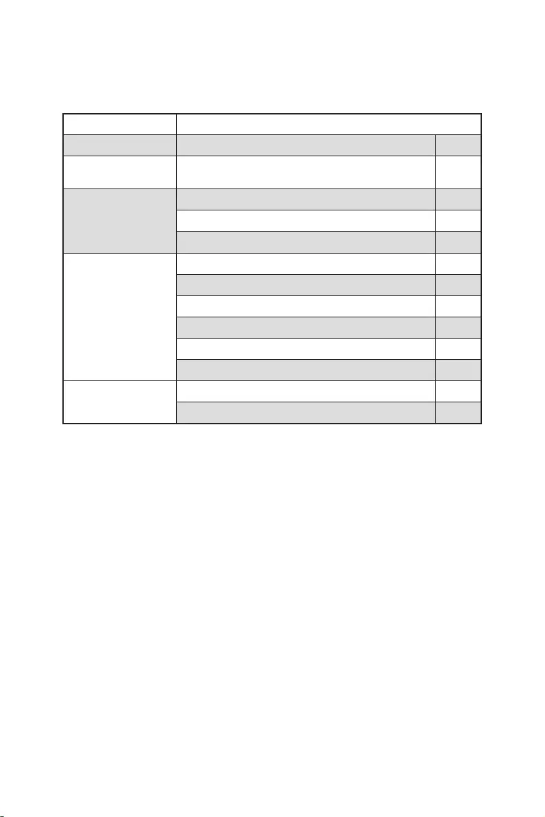
12 Package contents
Package contents
Please check the contents of your motherboard package. It should contain:
Motherboard MPG Z690 EDGE WIFI
Documentation Quick installation guide 1
USB drive with drivers & utilities 1
SATA 6G cables (2 cables/pack) 1
LED JRGB Y cable 1
LED JRAINBOW cable 1
1
Case Badge 1
EZ M.2 clip (1 set/pack) 2
MPG sticker 1
SATA cable stickers 1
Product registration card 1
Gift Small screwdriver set 1
Small brush 1
Important
If any of the above items are damaged or missing, please contact your retailer.

13
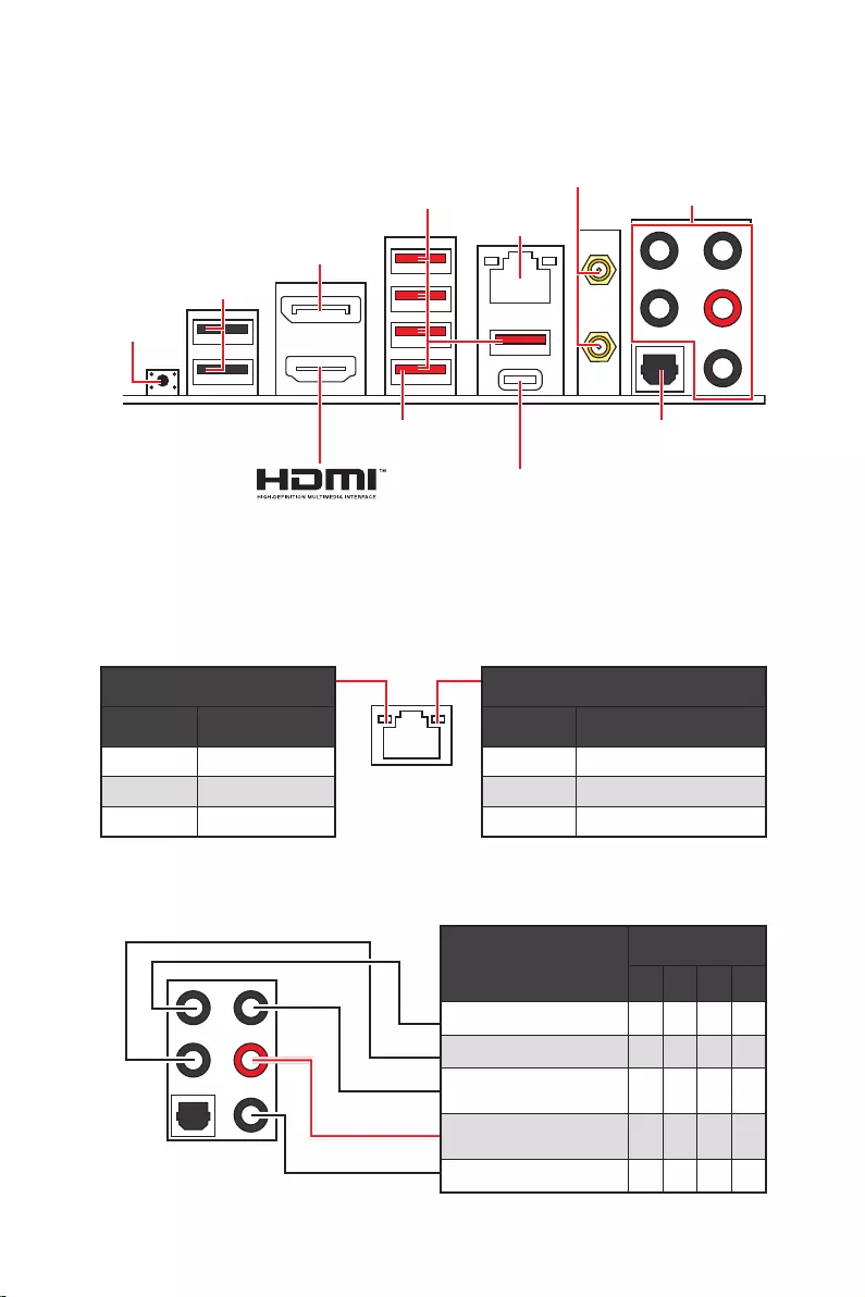
2468
Rear Speaker Out
Mic In
: empty)
Status Description
Off No link
Yellow Linked
Blinking Data activity
Status Description
Off 10 Mbps connection
Green 100/1000 Mbps connection
Orange 2.5 Gbps connection
38 for Updating BIOS with Flash BIOS
Button.
2.5 Gbps LAN
Audio Ports
Optical
DisplayPort
connectors
USB 3.2 Gen 2
Flash BIOS
Button
Flash BIOS Port
USB 2.0
USB 3.2 Gen 2×2
14
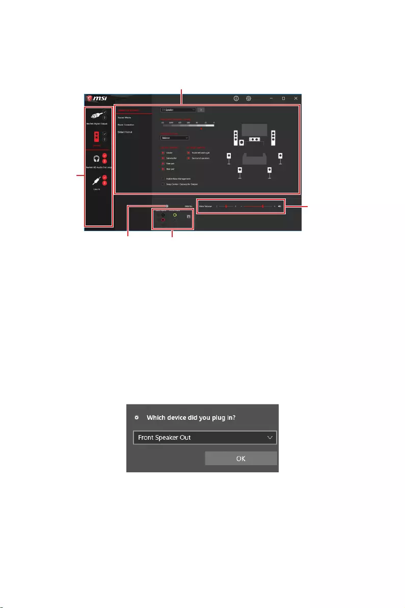
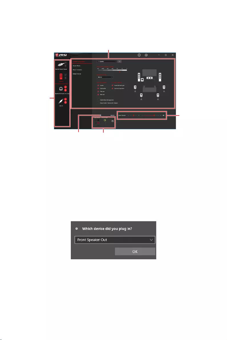
After Realtek Audio Console is installed. You can use it to change sound settings to get
better sound experience.
Device Selection
options. The check sign indicates the devices as default.
guidance of anticipated sound effect for both output and input device.
Main Volume
that you plugged in front or rear panel by adjust the bar.
Jack Status
computer.
When you plug into a device at an audio jack, a dialogue window will pop up asking you
which device is current connected.
Each jack corresponds to its default setting as shown on the next page.
Important
The pictures above for reference only and may vary from the product you purchased.
Jack Status
Connector Settings
Device
Selection
Main Volume
Application Enhancement

15
AUDIO INPUT
AUDIO INPUT
Rear Front
Side Center/
Subwoofer

16
Installing antennas
1. Screw the antennas tight to the antenna connectors as shown below.
2. Orient the antennas.
1
2

17
JUSB2
SYS_FAN5
SYS_FAN4
SYS_FAN3
SYS_FAN2
JBAT1
JTBT1
JTPM1
JRGB1
56
M2_3
JCI1
M2_1
SYS_FAN1
JDASH1
JUSB4
JUSB3
JUSB1
CPU_FAN1
SYS_FAN6
PUMP_FAN1
PCI_E1
PCI_E2
PCI_E3
PCI_E4
Processor Socket
CPU_PWR1 JRAINBOW3JSMB1
CPU_PWR2 JRAINBOW2
JAUD1
JFP2
JRAINBOW1
JPWRLED1
LED_SW1
JFP1
ATX_PWR1
DIMMB1
DIMMB2
DIMMA1
M2_2
M2_4
DIMMA2

18
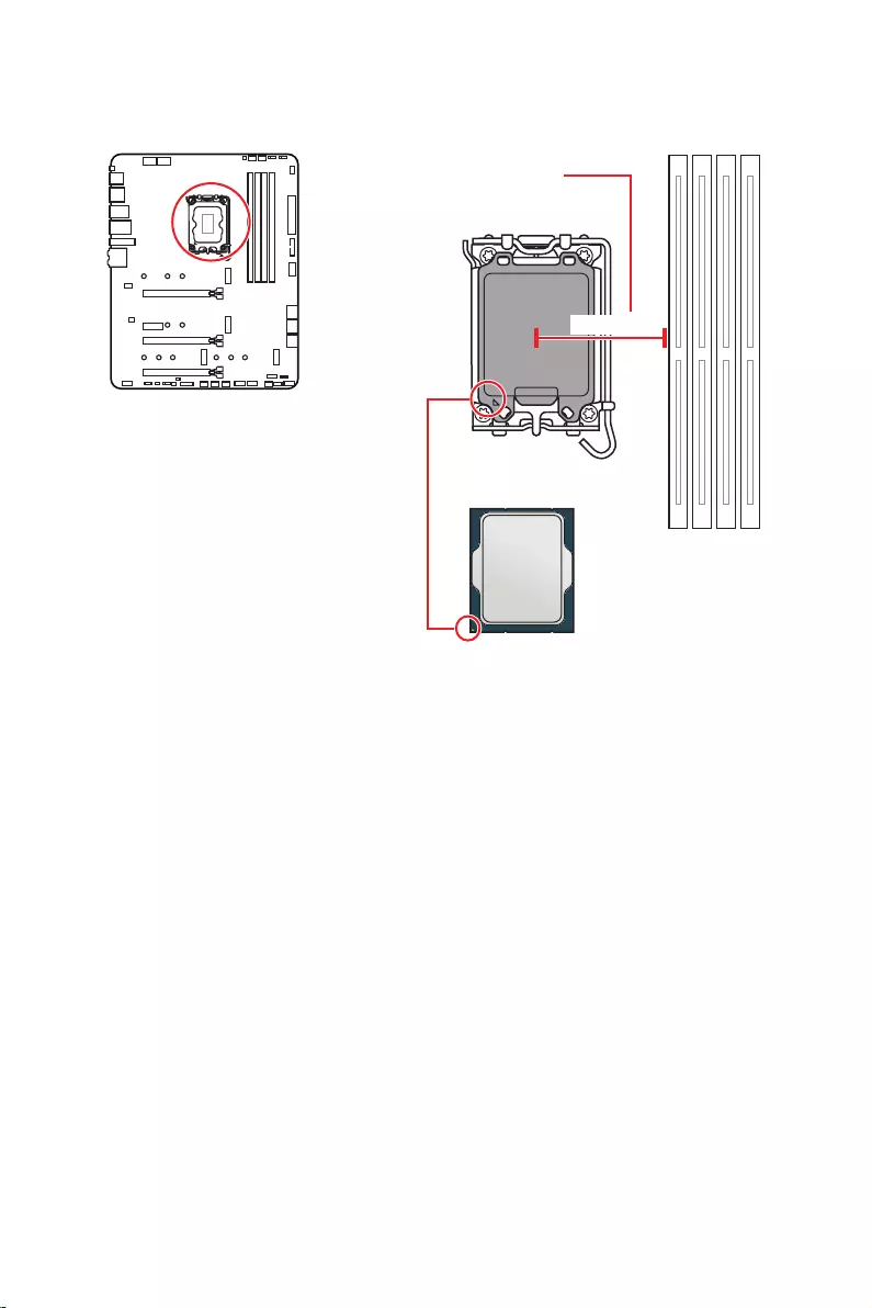
Important
Always unplug the power cord from the power outlet before installing or removing
the CPU.
Please retain the CPU protective cap after installing the processor. MSI will deal
with Return Merchandise Authorization (RMA) requests if only the motherboard comes
with the protective cap on the CPU socket.
When installing a CPU, always remember to install a CPU heatsink. A CPU heatsink
is necessary to prevent overheating and maintain system stability.
Confirm that the CPU heatsink has formed a tight seal with the CPU before booting
your system.
Overheating can seriously damage the CPU and motherboard. Always make sure
the cooling fans work properly to protect the CPU from overheating. Be sure to apply
an even layer of thermal paste (or thermal tape) between the CPU and the heatsink to
enhance heat dissipation.
Whenever the CPU is not installed, always protect the CPU socket pins by covering
the socket with the plastic cap.
If you purchased a separate CPU and heatsink/ cooler, Please refer to the
documentation in the heatsink/ cooler package for more details about installation.
This motherboard is designed to support overclocking. Before attempting to
overclock, please make sure that all other system components can tolerate
overclocking. Any attempt to operate beyond product specifications is not
recommended. MSI® does not guarantee the damages or risks caused by inadequate
operation beyond product specifications.
The surface of the LGA1700 CPU has
four notches and a golden triangle to
assist in correctly lining up the CPU for
motherboard placement. The golden
triangle is the Pin 1 indicator.
Distance from the center of the
CPU to the nearest DIMM slot.
52.55 mm

19
DIMM Slots
Memory module installation recommendation
Important
Always insert memory modules in the slot first.
To ensure system stability for Dual channel mode, memory modules must be of the
same type, number and density.
Some memory modules may operate at a lower frequency than the marked value
when overclocking due to the memory frequency operates dependent on its Serial
Presence Detect (SPD). Go to BIOS and find the to set the memory
frequency if you want to operate the memory at the marked or at a higher frequency.
It is recommended to use a more efficient memory cooling system for full DIMMs
installation or overclocking.
The stability and compatibility of installed memory module depend on installed CPU
and devices when overclocking.
Please refer www.msi.com for more information on compatible memory.
DIMMA1 DIMMB1
Channel A Channel B
DIMMA2 DIMMB2
DIMMA2 DIMMA2
DIMMB2
DIMMA1
DIMMA2
DIMMB1
DIMMB2

20
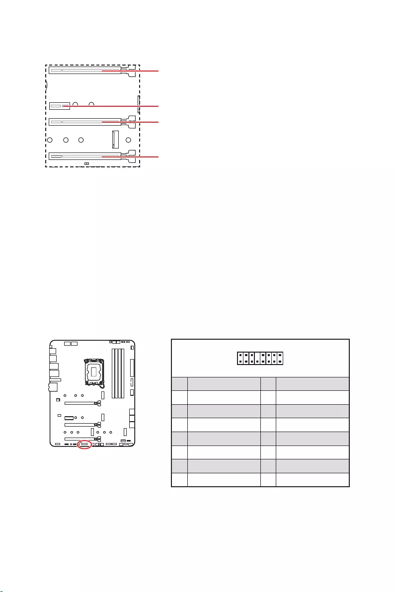
: PCIe 5.0 x16 (From CPU)
: PCIe 3.0 x1 (From Z690 chipset)
: PCIe 3.0 x4 (From Z690 chipset)
: PCIe 3.0 x4 (From Z690 chipset)
Important
If you install a large and heavy graphics card, you need to use a tool such as MSI
to support its weight to prevent deformation of
the slot.
For a single PCIe x16 expansion card installation with optimum performance, using
the slot is recommended.
When adding or removing expansion cards, always turn off the power supply and
unplug the power supply power cable from the power outlet. Read the expansion
card’s documentation to check for any necessary additional hardware or software
changes.
1
2 16
15
1 TBT_Force_PWR 2 TBT_S0IX_Entry_REQ
3 TBT_CIO_Plug_Event# 4 TBT_S0IX_Entry_ACK
5 SLP_S3#_TBT 6 TBT_PSON_Override_N
7 SLP_S5#_TBT 8 No pin
9 Ground 10 SMBCLK_VSB
11 DG_PEWake 12 SMBDATA_VSB
13 TBT_RTD3_PWR_EN 14 Ground
15 TBT_Card_DET_R# 16 PD_IRQ#

21
M2_1
M2_2
M2_4
M2_3
Important
Intel® RST only supports PCIe M.2 SSD with UEFI
ROM.
M2_2~4 support Intel® Optane™ Memory.
Installing M.2 module
1. Loosen the screws of M.2 SHIELD FROZR heatsink.
2. Remove the M.2 SHIELD FROZR and remove the protective films from the thermal
pads.
2
2
2
2
1
1
1
1
11
1
M2_2
M2_3
M2_1
M2_4

22
30º30º
5
6
6
6
66 6
6
4
3
3. If there is no EZ M.2 Clip installed, please install the supplied EZ M.2 Clip kit in the
M.2 slot according to your SSD length.
4.
5. Rotate the EZ M.2 Clip to fix the M.2 SSD.
6. Put the M.2 SHIELD FROZR heatsink back in place and secure it.

23
These connectors are SATA 6Gb/s interface ports. Each connector can connect to one
SATA device.
SATAA
SATA7
SATA5
SATAB
SATA8
SATA6
Important
transmission otherwise.
SATA cables have identical plugs on either sides of the cable. However, it is
recommended that the flat connector be connected to the motherboard for space
saving purposes.
This connector allows you to connect audio jacks on the front panel.
1
2 10
9
1 MIC L 2 Ground
3 MIC R 4 NC
5 Head Phone R 6 MIC Detection
7 SENSE_SEND 8 No Pin
9 Head Phone L 10 Head Phone Detection

24
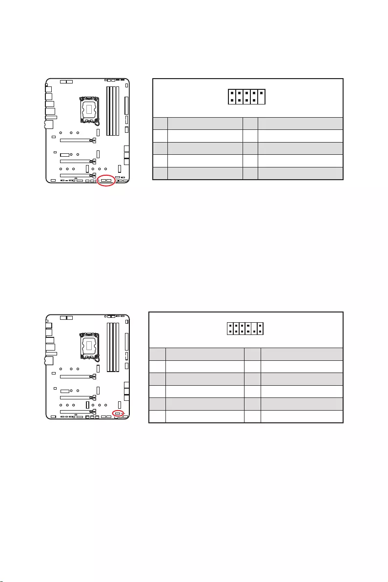
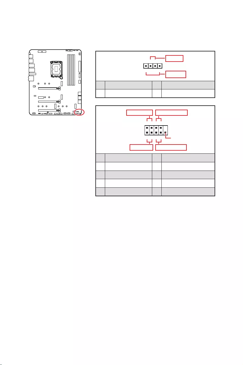
These connectors connect to the switches and LEDs on the front panel.
1
2 10
9
+
+
+
+
Power LED
HDD LED Reset Switch
Reserved
Power Switch
JFP1
1 HDD LED + 2 Power LED +
3 4
5 Reset Switch 6 Power Switch
7 Reset Switch 8 Power Switch
9 Reserved 10 No Pin
1
JFP2
+
+
Speaker
Buzzer
1 2 Buzzer +
3 4 Speaker +
25
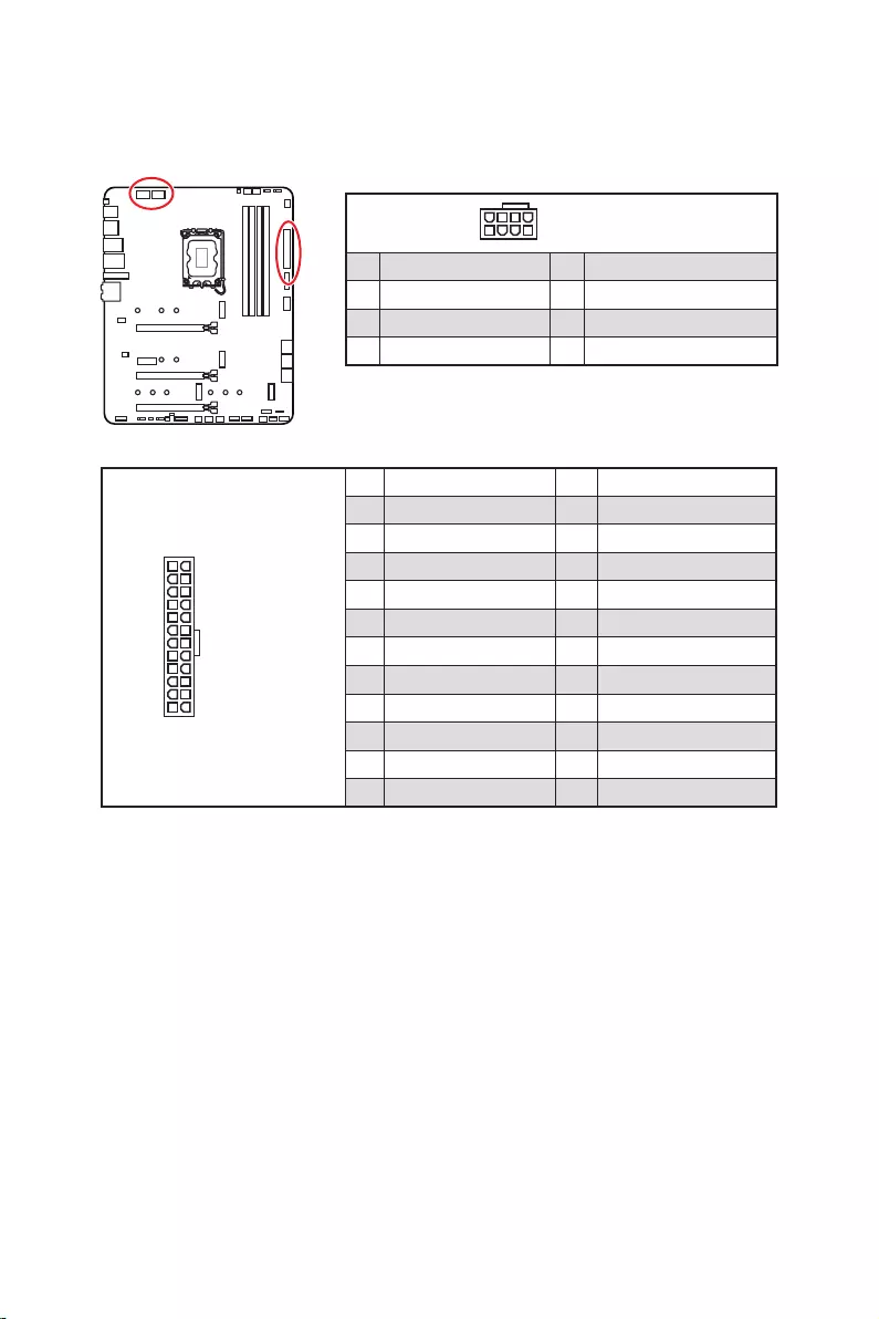
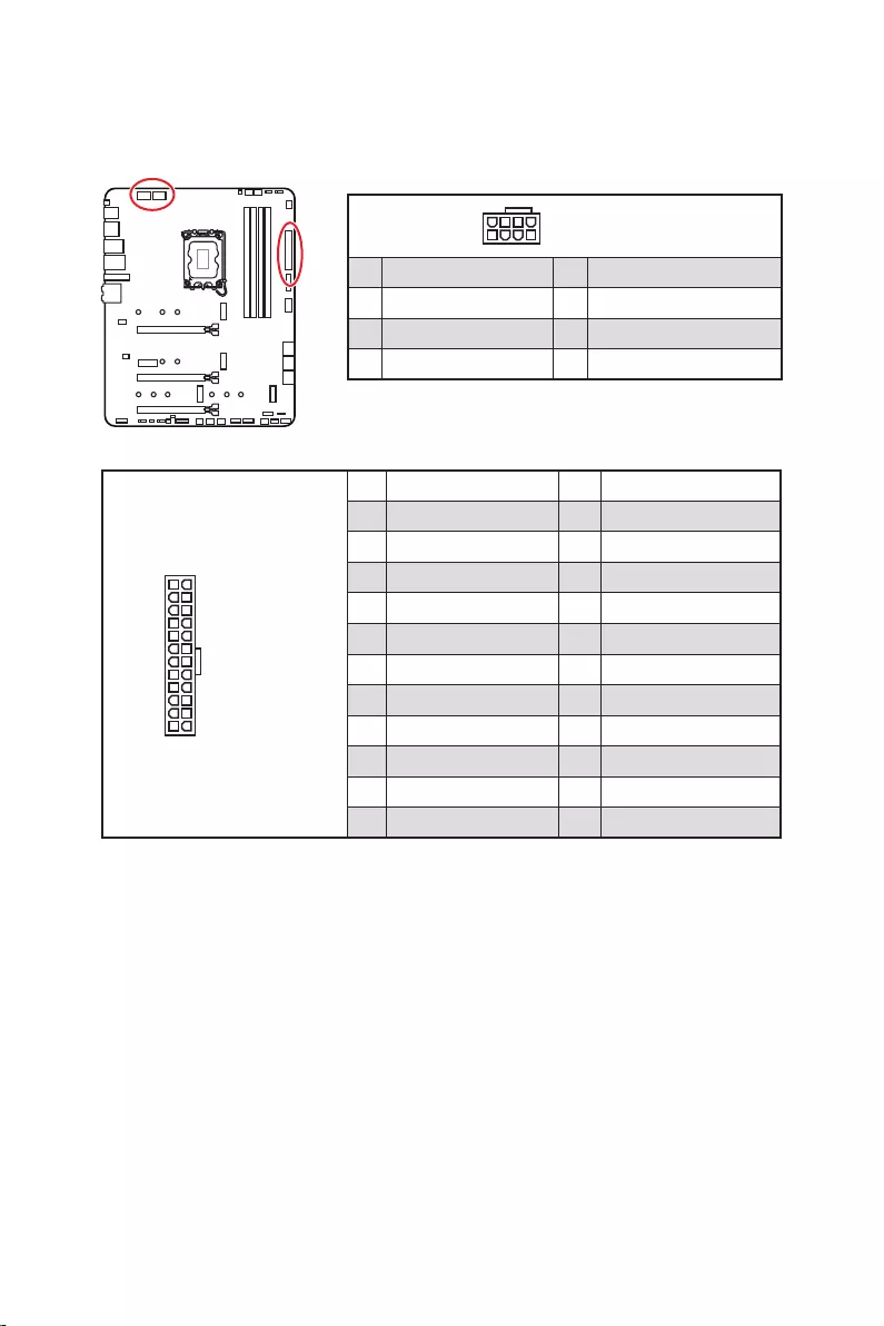
24
131
12
ATX_PWR1
1 +3.3V 13 +3.3V
2 +3.3V 14
3 Ground 15 Ground
4 +5V 16
5 Ground 17 Ground
6 +5V 18 Ground
7 Ground 19 Ground
8 PWR OK 20 Res
9 5VSB 21 +5V
10 +12V 22 +5V
11 +12V 23 +5V
12 +3.3V 24 Ground
5
4 1
8CPU_PWR1~2
1 Ground 5 +12V
2 Ground 6 +12V
3 Ground 7 +12V
4 Ground 8 +12V
Important
Make sure that all the power cables are securely connected to a proper ATX power
supply to ensure stable operation of the motherboard.
These connectors allow you to connect an ATX power supply.

26
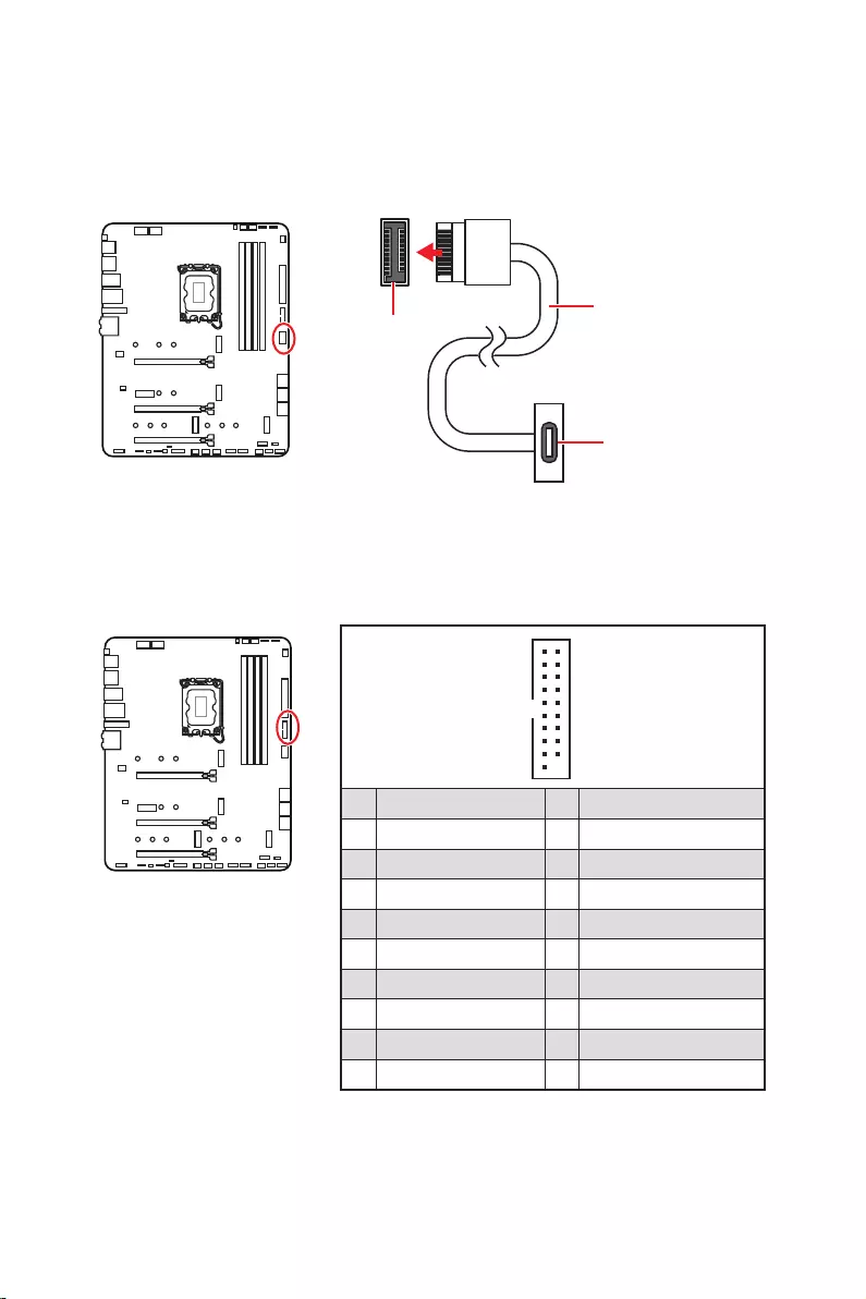
front panel. The connector possesses a foolproof design. When you connect the cable,
be sure to connect it with the corresponding orientation.
This connector allows you to connect USB 3.2 Gen 1 5Gbps ports on the front panel.
Important
Note that the Power and Ground pins must be connected correctly to avoid possible
damage.
1
10 11
20
1 Power 11 USB2.0+
2 USB3_RX_DN 12
3 USB3_RX_DP 13 Ground
4 Ground 14 USB3_TX_C_DP
5 USB3_TX_C_DN 15 USB3_TX_C_DN
6 USB3_TX_C_DP 16 Ground
7 Ground 17 USB3_RX_DP
8 18 USB3_RX_DN
9 USB2.0+ 19 Power
10 Ground 20 No Pin
JUSB4
the front panel
27
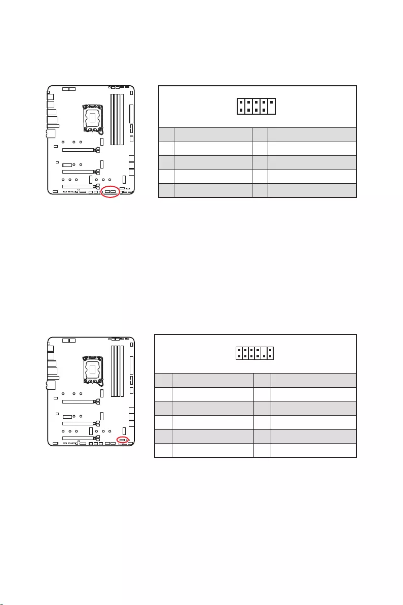
These connectors allow you to connect USB 2.0 ports on the front panel.
1
2 10
9
1 VCC 2 VCC
3 4
5 USB0+ 6 USB1+
7 Ground 8 Ground
9 No Pin 10 NC
Important
Note that the VCC and Ground pins must be connected correctly to avoid possible
damage.
In order to recharge your iPad,iPhone and iPod through USB ports, please install
MSI® Center utility.
1
2 12
11
1 SPI Power 2 SPI Chip Select
3
Master In Slave Out (SPI Data)
4
Master Out Slave In (SPI Data)
5 Reserved 6 SPI Clock
7 Ground 8 SPI Reset
9 Reserved 10 No Pin
11 Reserved 12 Interrupt Request
This connector is for TPM (Trusted Platform Module). Please refer to the TPM security
platform manual for more details and usages.

28
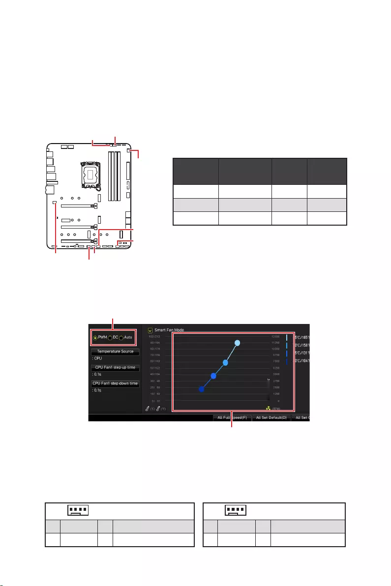
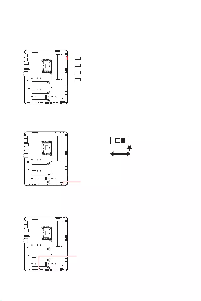
Fan connectors can be classified as PWM (Pulse Width Modulation) Mode or DC Mode.
PWM Mode fan connectors provide constant 12V output and adjust fan speed with
speed control signal. DC Mode fan connectors control fan speed by changing voltage.
The auto mode fan connectors can automatically detect PWM and DC mode. However,
you can follow the instruction below to adjust the fan connector to PWM or DC Mode
manually.
You can switch between PWM mode and DC mode and adjust fan speed in
.
Select PWM mode or mode
Important
Make sure fans are working properly after switching the PWM/ DC mode.
There are gradient points of the fan speed that allow you to adjust
fan speed in relation to CPU temperature.
Pin definition of fan connectors
Default
fan mode Max.
current Max.
CPU_FAN1 Auto mode 2A 24W
PUMP_FAN1 PWM mode 3A 36W
SYS_FAN1~6 DC mode 1A 12W
1 PWM Mode pin definition
1 Ground 2 +12V
3 Sense 4 Speed Control Signal
1
1 Ground 2 Voltage Control
3 Sense 4 NC
SYS_FAN1
SYS_FAN3
SYS_FAN5
SYS_FAN4
PUMP_FAN1
CPU_FAN1
SYS_FAN2
SYS_FAN6

29
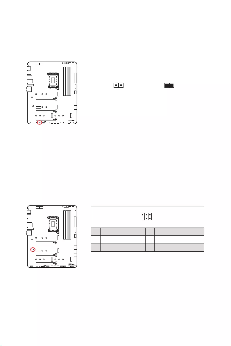
This connector allows you to connect the chassis intrusion switch cable.
Normal
(default) Trigger the chassis
intrusion event
1. Connect the connector to the chassis intrusion switch/ sensor on the chassis.
2. Close the chassis cover.
3. Go to .
4. Set to Enabled.
5. Press F10 to save and exit and then press the Enter key to select Yes.
6. Once the chassis cover is opened again, a warning message will be displayed on
screen when the computer is turned on.
1. Go to .
2. Set to Reset.
3. Press F10 to save and exit and then press the Enter key to select Yes.

30
There is CMOS memory onboard that is external powered from a battery located on
the motherboard to save system configuration data. If you want to clear the system
configuration, set the jumpers to clear the CMOS memory.
Keep Data
(default) Clear CMOS/
Reset BIOS
1. Power off the computer and unplug the power cord.
2. Use a jumper cap to short
3. Remove the jumper cap from .
4. Plug the power cord and Power on the computer.
This connector is used to connect an optional Tuning Controller module.
1
2 6
5
1 No Pin 2 NC
3 MCU_SMB_SCL_M 4 MCU_SMB_SDA_M
5 VCC5 6 Ground

31
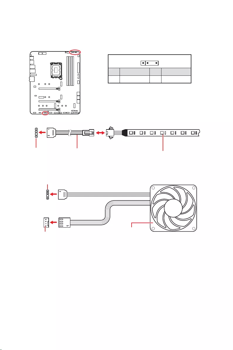
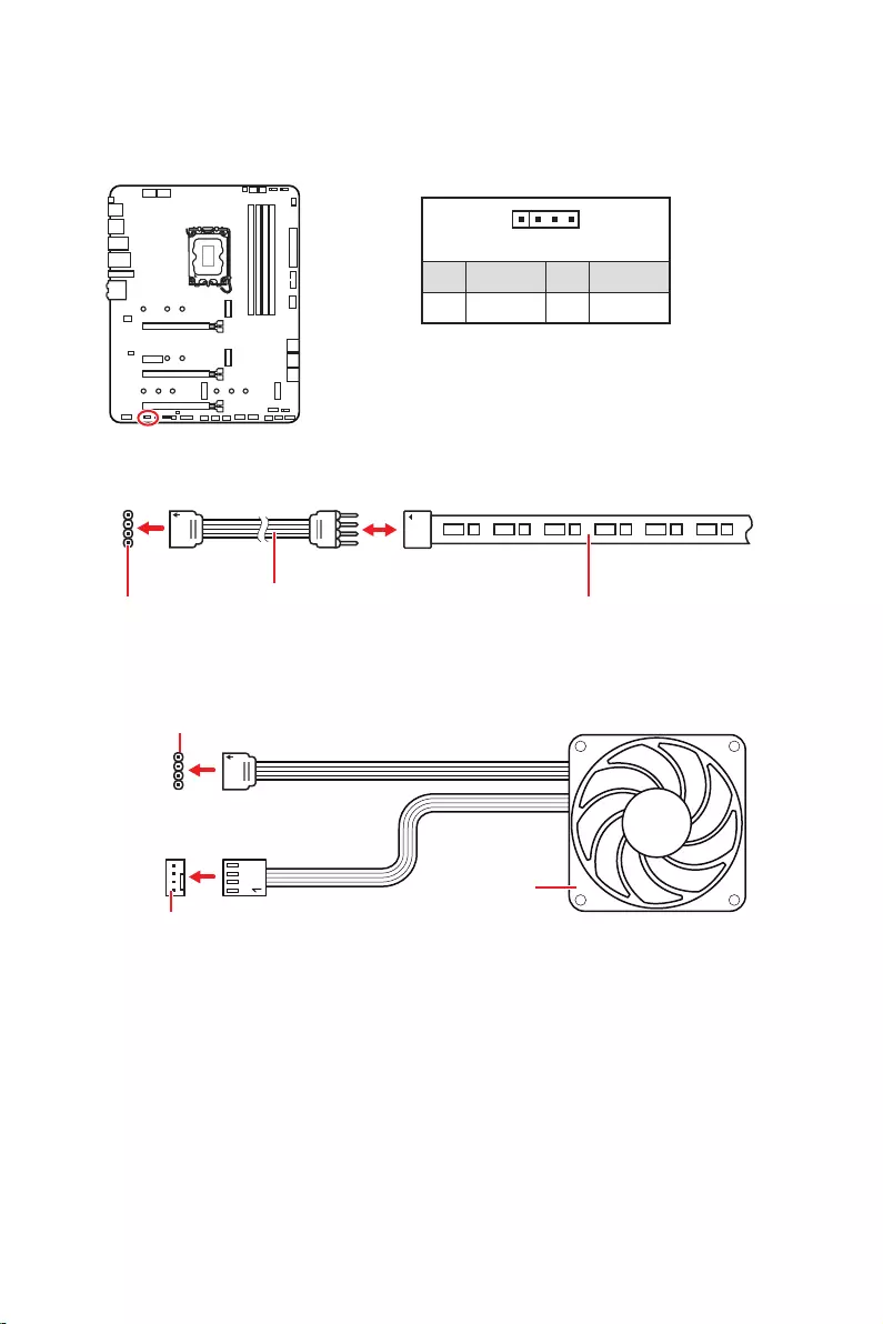
Important
The JRGB connector supports up to 2 meters continuous 5050 RGB LED strips
(12V/G/R/B) with the maximum power rating of 3A (12V).
Always turn off the power supply and unplug the power cord from the power outlet
before installing or removing the RGB LED strip.
Please use MSI’s software to control the extended LED strip.
The JRGB connector allows you to connect the 5050 RGB LED strips 12V.
1
GRB
JRGB
connector
JRGB extension
cable 5050 RGB LED strips 12V
1
1 +12V 2 G
3 R 4 B
1
1
GRB
JRGB connector
System Fan connector
RGB LED Fan
32
1
1
1
D
+5V
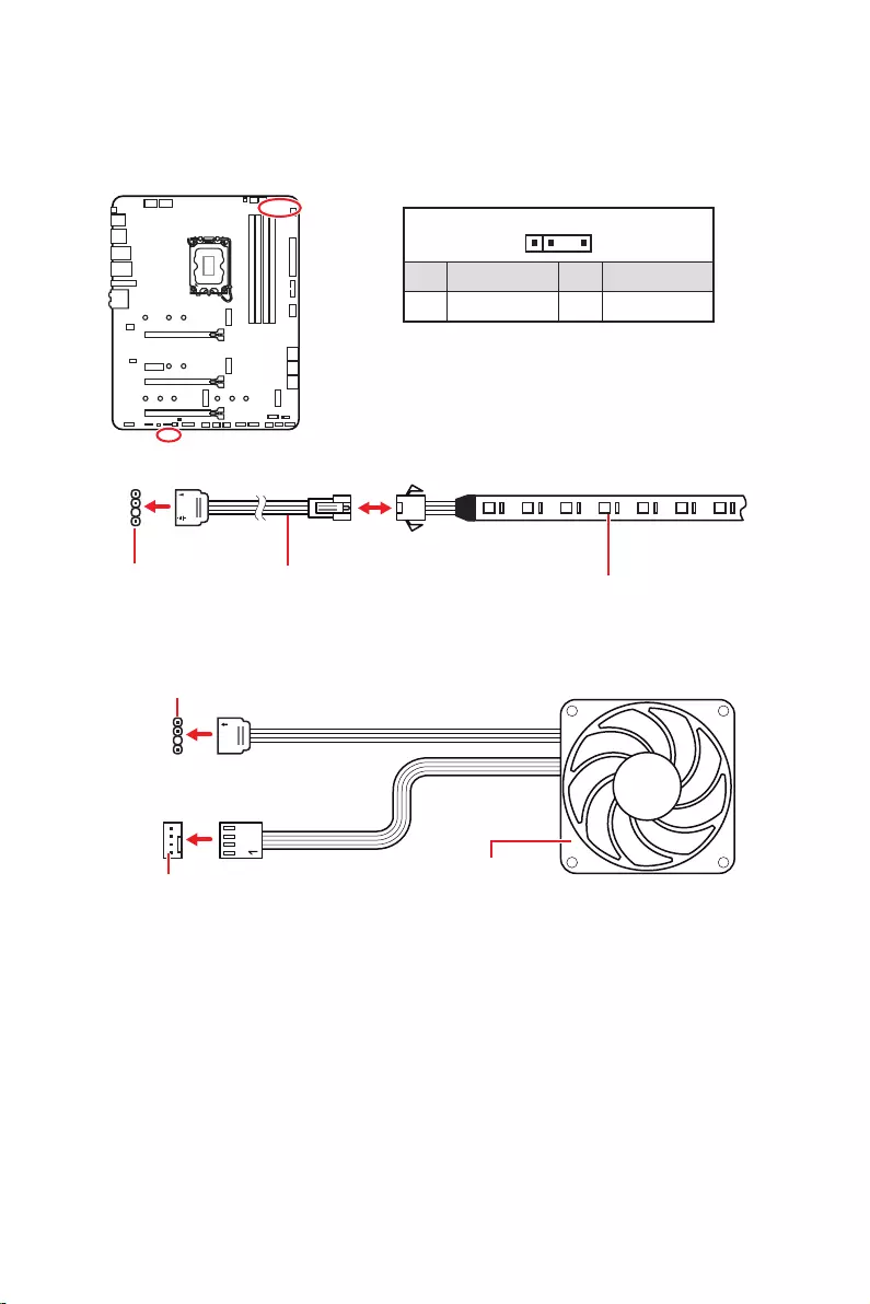
Do not connect the wrong type of LED strips. The JRGB connector and the JRAINBOW
connector provide different voltages, and connecting the 5V LED strip to the JRGB
connector will result in damage to the LED strip.
Important
The JRAINBOW connector supports up to 75 LEDs WS2812B Individually
Addressable RGB LED strips (5V/Data/Ground) with the maximum power rating of 3A
(5V). In the case of 20% brightness, the connector supports up to 200 LEDs.
Always turn off the power supply and unplug the power cord from the power outlet
before installing or removing the RGB LED strip.
Please use MSI’s software to control the extended LED strip.
The JRAINBOW connectors allow you to connect the WS2812B Individually
Addressable RGB LED strips 5V.
JRAINBOW
connector
JRAINBOW connector
System Fan connector
JRAINBOW
extension cable WS2812B Individually
Addressable RGB LED strips 5V
1
1 +5V 2 Data
3 No Pin 4 Ground
Addressable RGB LED Fan

33
These LEDs indicate the debug status of the motherboard.
or fail.
This switch is used to switch on/ off all the LEDs of motherboard.
LED_SW1
LED_OFF LED_ON
(Default)
This connector is used by retailers to demonstrate onboard LED lights.

34
Please download and update the latest utilities and drivers at www.msi.com
1. Power on the computer.
2. Insert the Windows 10/ Windows 11 installation disc/ USB into your computer.
3. Press the Restart button on the computer case.
4. Press F11
Menu.
5. Select the Windows 10/ Windows 11 installation disc/USB from the Boot Menu.
6. Press any key if screen shows message.
If not please skip this step.
7. Follow the instructions on the screen to install Windows 10/ Windows 11.
Installing Drivers
1. Start up your computer in Windows 10/ Windows 11.
2. Insert MSI® USB Drive into the USB port.
3. Click the
select Run DVDSetup.exe to open the installer. If you turn off the AutoPlay feature
from the Windows Control Panel, you can still manually execute the DVDSetup.exe
from the root path of the MSI USB Drive.
4. The installer will find and list all necessary drivers in the tab.
5. Click the Install
6. The drivers installation will then be in progress, after it has finished it will prompt
you to restart.
7. Click button to finish.
8. Restart your computer.
MSI Center is an application that helps you easily optimize game settings and smoothly
use content creation softwares. It also allows you to control and synchronize LED
light effects on PCs and other MSI products. With MSI Center, you can customize ideal
modes, monitor system performance, and adjust fan speed.
If you would like to know more information about MSI Center, please
refer to
http://download.msi.com/manual/mb/MSICENTER.pdf
or scan the QR code to access.
Important
Functions may vary depending on the product you have.

35
MSI UEFI BIOS is compatible with UEFI (Unified Extensible Firmware Interface)
architecture. UEFI has many new functions and advantages that traditional BIOS
cannot achieve, and it will completely replace BIOS in the future. The MSI UEFI
BIOS uses UEFI as the default boot mode to take full advantage of the new chipset’s
capabilities.
Important
The term BIOS in this user guide refers to UEFI BIOS unless otherwise noted.
test process. And also eliminates the time to switch to CSM mode during POST.
Supports for hard drive partitions larger than 2 TB.
Supports more than 4 primary partitions with a GUID Partition Table (GPT).
Supports unlimited number of partitions.
compatibility.
ensure that no malware tampers with the startup process.
warning message
this graphics card.
Important
We recommend that you to replace with a GOP/UEFI compatible graphics card or
using integrated graphics from CPU for having normal function.
1. Power on your computer.
2. Press Delete key, when the
message appears on the screen during the boot process.
3. After entering the BIOS, you can check the at the top of the screen.

36
The default settings offer the optimal performance for system stability in normal
conditions. You should to avoid possible system
damage or failure booting unless you are familiar with BIOS.
Important
BIOS items are continuously update for better system performance. Therefore, the
description may be slightly different from the latest BIOS and should be for reference
only. You could also refer to the information panel for BIOS item description.
The BIOS screens, options and settings will vary depending on your system.
Press Delete key, when the
Menu message appears on the screen during the boot process.
Function key
F1: General Help list
F2: Add/ Remove a favorite item
F3: Enter Favorites menu
F4: Enter CPU Specifications menu
F5
F6: Load optimized defaults
F7: Switch between Advanced mode and EZ mode
F8: Load Overclocking Profile
F9: Save Overclocking Profile
F10: Save Change and Reset*
F12: Take a screenshot and save it to USB flash drive (FAT/ FAT32 format only).
: Enter Search page
* When you press F10, a confirmation window appears and it provides the modification
information. Select between Yes or No to confirm your choice.
If you’d like to know more instructions on setting up the BIOS, please
refer to
http://download.msi.com/manual/mb/Intel600BIOS.pdf
or scan the QR code to access.

37
You might need to restore the default BIOS setting to solve certain problems. There
are several ways to reset BIOS:
Go to BIOS and press F6 to load optimized defaults.
Short the jumper on the motherboard.
Important
Be sure the computer is off before clearing CMOS data. Please refer to the
jumper section for resetting BIOS.
Before updating:
Please download the latest BIOS file that matches your motherboard model from MSI
website. And then save the BIOS file into the USB flash drive.
Updating BIOS:
1.
motherboard doesn‘t has this switch.
2. Insert the USB flash drive that contains the update file into the USB port.
3. Please refer the following methods to enter flash mode.
Reboot and press key during POST and click on Yes to reboot the
system.
Reboot and press Del key during POST to enter BIOS. Click the button
and click on Yes to reboot the system.
4. Select a BIOS file to perform the BIOS update process.
5. When prompted click on Yes to start recovering BIOS.
6. After the flashing process is 100% completed, the system will reboot
automatically.

38
Before updating:
Make sure the LAN driver is already installed and the internet connection is set
properly.
Please close all other application software before updating the BIOS.
To update BIOS:
1. Install and launch MSI Center and go to Support page.
2. Select and click on button.
3. Select the BIOS file and click on Install button.
4. The installation reminder will appear, then click the Install button on it.
5. The system will automatically restart to update BIOS.
6. After the flashing process is 100% completed, the system will restart
automatically.
1. Please download the latest BIOS file that matches your motherboard model from
the MSI® website.
2. Rename the BIOS file to MSI.ROM, and save it to the root of the USB storage
device.
3. Connect the power supply to and . (No need to install CPU
and memory.)
4. Plug the USB storage device that contains the MSI.ROM file into the
Port on the rear I/O panel.
5. Press the Button to flash BIOS, and the LED starts flashing.
6. The LED will be turned off when the process is completed.

1
Inhalt
Inhalt
…………………………………………………………………………..3
Hinweise zum Gehäuseabstandshalter ……………………………………………………….. 4
Hinweis zur Schadensvermeidung ………………………………………………………………. 4
Spezifikationen ……………………………………………………………………………….. 5
Packungsinhalt ………………………………………………………………………………12
………………………………………………………………………………..13
LAN Port LED Zustandstabelle …………………………………………………………………. 13
Konfiguration der Audioanschlüsse …………………………………………………………… 13
Realtek Audio Console …………………………………………………………………………….. 14
Übersicht der Komponenten …………………………………………………………….17
CPU Sockel …………………………………………………………………………………………….. 18
DIMM Steckplätze ……………………………………………………………………………………. 19
PCI_E1~4: PCIe Erweiterungssteckplätze ………………………………………………….. 20
……………………………….. 20
M2_1~4: M.2 Steckplätze (Key M) ……………………………………………………………… 21
SATA5~8 & SATAA~B: SATA 6Gb/s Anschlüsse …………………………………………… 23
JAUD1: Audioanschluss des Frontpanels …………………………………………………… 23
…………………………………………………………. 24
CPU_PWR1~2, ATX_PWR1: Stromanschlüsse ……………………………………………. 25
…………………………………………………….. 26
JUSB3: USB 3.2 Gen 1 Anschluss ……………………………………………………………… 26
JUSB1~2: USB 2.0 Anschlüsse ………………………………………………………………….. 27
JTPM1: TPM Anschluss ……………………………………………………………………………. 27
CPU_FAN1, PUMP_FAN1, SYS_FAN1~6: Stromanschlüsse für Lüfter ………….. 28
JCI1: Gehäusekontaktanschluss ……………………………………………………………….. 29
JBAT1: Clear CMOS Steckbrücke (Reset BIOS) …………………………………………… 30
………………………………………………………. 30
JRGB1: RGB LED Anschluss …………………………………………………………………….. 31
…………………… 32
……………………………………………………………………………….. 33
EZ DEBUG LED ……………………………………………………………………………………….. 33
LED_SW1: EZ LED Steuerung …………………………………………………………………… 33
JPWRLED1: LED Stromzufuhr ………………………………………………………………….. 33
……………………………………….. 34
Installation von Windows 10/ Windows 11 ………………………………………………….. 34
Deutsch

2Inhalt
Installation von Treibern ………………………………………………………………………….. 34
MSI Center ……………………………………………………………………………………………… 35
……………………………………………………………………………………..36
BIOS Setup ……………………………………………………………………………………………… 37
Öffnen des BIOS Setups……………………………………………………………………………. 37
………………………………………………………………………….. 37
Reset des BIOS ……………………………………………………………………………………….. 38
Aktualisierung des BIOS …………………………………………………………………………… 38

3
Die im Paket enthaltene Komponenten sind der Beschädigung durch
elektrostatischen Entladung (ESD). Beachten Sie bitte die folgenden Hinweise, um die
erfolgreichen Computermontage sicherzustellen.
Stellen Sie sicher, dass alle Komponenten fest angeschlossen sind. Lockere
Steckverbindungen können Probleme verursachen, zum Beispiel: Der Computer
erkennt eine Komponente nicht oder startet nicht.
Halten Sie das Motherboard nur an den Rändern fest, und verhindern Sie die
Berührung der sensiblen Komponenten.
Um eine Beschädigung der Komponenten durch elektrostatische Entladung
(ESD) zu vermeiden, sollten Sie eines elektrostatischen Armbands während der
Handhabung des Motherboards tragen. Wenn kein elektrostatischen Handgelenkband
vorhanden ist, sollten Sie Ihre statische Elektrizität ableiten, indem Sie ein anderes
Metallobjekt berühren, bevor Sie das Motherboard anfassen.
Bewahren Sie das Motherboard in einer elektrostatische Abschirmung oder einem
Antistatiktuch auf, wenn das Motherboard nicht installiert ist.
Überprüfen Sie vor dem Einschalten des Computers, dass sich keine losen
Schrauben und andere Bauteile auf dem Motherboard oder im Computergehäuse
befinden
Bitte starten Sie den Computer nicht, bevor die Installation abgeschlossen ist.
Dies könnte permanente Schäden an den Komponenten sowie zu das Verletzung des
Benutzers verursachen.
Sollten Sie Hilfe bei der Installation benötigen, wenden Sie sich bitte an einen
Schalten Sie die Stromversorgung aus und ziehen Sie das das Stromkabel ab, bevor
Bewahren Sie die Bedienungsanleitung als künftige Referenz auf.
Halten Sie das Motherboard von Feuchtigkeit fern
Bitte stellen Sie sicher, dass Ihre Netzspannung den Hinweisen auf dem Netzteil vor
Anschluss des Netzteils an die Steckdose entspricht
Verlegen Sie das Netzkabel so, dass niemand versehentlich darauf treten kann.
Stellen Sie nichts auf dem Netzkabel ab.
Falls einer der folgenden Umstände eintritt, lassen Sie bitte das Motherboard von
Kundendienstpersonal prüfen:
Flüssigkeit ist in dem Computer eingedrungen.
Das Motherboard wurde Feuchtigkeit ausgesetzt.
Das Motherboard funktioniert nicht richtig oder Sie können es nicht wie in der
Bedienungsanleitung beschrieben bedienen.
Das Motherboard ist heruntergefallen und beschädigt.
Das Motherboard weist offensichtlich Zeichen eines Schadens auf.
Nutzen und lagern Sie das Gerät nicht an Stellen, an denen Temperaturen von mehr

4
Um eine Beschädigung des Motherboards zu vermeiden, sind unnötige Abstandshalter
. Die
Schilder „Case Standoff Keep Out Zone (Gehäuseabstandszone freihalten )“ auf der
Rückseite des Motherboards (wie unten gezeigt) dienen als entsprechender Hinweis
für den Anwender.
Um jedes Schraubenloch ist eine Schutzfarbe aufgedruckt, um ein Verkratzen der
Teile zu verhindern.

5
Spezifikationen
Spezifikationen
Unterstützt Intel® Core™ der 12. Generation Prozessoren,
Pentium® Gold und Celeron® Prozessoren*
Prozessor Sockel LGA1700
erhalten, wenn neue Prozessoren veröffentlicht werden.
Intel® Z690 Chipsatz
Speicher
4x DDR5 Speicherplätze, aufrüstbar bis 128 GB*
Unterstützt JEDEC Standard DDR5 4800/ 6666 (OC)
MHz
Unterstützt Intel® XMP 3.0 OC
*Weitere Informationen zu kompatiblen Speichermodulen finden Sie unter:
www.msi.com.
3x PCIe x16 Steckplätze
PCI_E1 Steckplatz (von CPU)
Unterstützt PCIe 5.0 x16
PCI_E3 & PCI_E4 Steckplatz (von Z690 Chipsatz)
Unterstützt PCIe 3.0 x4
1x PCIe 3.0 x1 Steckplatz (von Z690 Chipsatz)
Unterstützt AMD CrossFire™ Technologie
1x HDMI 2.1 mit HDR Anschluss, Unterstützung einer
maximalen Auflösung von 4K 60Hz*/**
1x DisplayPort 1.4 Anschluss mit HBR3, Unterstützung
einer maximalen Auflösung von 4K 60Hz*/**
*Es ist verfügbar für den Prozessor mit integrierter Grafik.
variieren.
Fortsetzung auf der nächsten Seite

6Spezifikationen
Fortsetzung der vorherigen Seite
Speicher
6x SATA 6Gb/s Anschlüsse
SATA5~8 Steckplatz (von Z690 Chipsatz)
SATAA~B (von ASMedia ASM1061)
4x M.2 Steckplätze (Key M)
M2_1 Steckplatz (von CPU)
Unterstützt PCIe 4.0 x4
Unterstützt 2260/ 2280/ 22110 Speichergeräte
M2_2 Steckplatz (von Z690 Chipsatz)
Unterstützt PCIe 4.0 x4
Unterstützt 2260/ 2280 Speichergeräte
M2_3 Steckplatz (von Z690 Chipsatz)
Unterstützt PCIe 4.0 x4
Unterstützt bis zu SATA 6Gb/s
Unterstützt 2242/ 2260/ 2280 Speichergeräte
M2_4 Steckplatz (von Z690 Chipsatz)
Unterstützt PCIe 4.0 x4
Unterstützt bis zu SATA 6Gb/s
Unterstützt 2242/ 2260/ 2280 Speichergeräte
M2_2~4 unterstützt Intel® Optane™ Memory
Unterstützt Intel® Smart Response Technologie für Intel
Core™ Prozessoren
Unterstützt RAID 0, RAID 1, RAID 5 und RAID 10 für SATA
Speichergeräte*
Unterstützt RAID 0, RAID 1 und RAID 5 für M.2PCIe
Speichergeräte
Realtek® ALC4080
Fortsetzung auf der nächsten Seite

7
Spezifikationen
Fortsetzung der vorherigen Seite
Intel® Z690 Chipsatz
rückseitigen Anschlussleiste
rückseitigen Anschlussleiste)
Anschlussleiste
2x USB 3.2 Gen 1 5Gbit/s Anschlüsse stehen durch die
internen USB Anschlüsse
USB 2.0 Hub GL850G
4x USB 2.0 Anschlüsse stehen durch die internen USB
Anschlüsse
1x Intel® I225V 2.5Gbit/s LAN Controller
vorinstalliert
(160MHz) mit Datenraten bis zu 2,4Gbit/s
Unterstützt 802.11 a/ b/ g/ n/ ac/ ax
Unterstützt Bluetooth® 5.2**, FIPS, FISMA
Windows 10 version 21H1 und Windows 11 bereit sein.
** Bluetooth 5.2 wird in Windows 10 Version 21H1 und Windows 11 verfügbar
sein.
1x Flash BIOS Taste
2x USB 2.0 Anschlüsse
1x DisplayPort
1x HDMI Anschluss
1 x 2,5Gbit/s LAN (RJ45) Anschluss
5x Audiobuchsen
Fortsetzung auf der nächsten Seite

8Spezifikationen
Fortsetzung der vorherigen Seite
6x SATA 6Gb/s Anschlüsse
4x M.2 Steckplätze (Key M)
1x USB 3.2 Gen 1 5Gbit/s Anschluss (unterstützt
zusätzliche 2 USB 3.2 Gen 1 5Gbit/s Anschlüsse)
2x USB 2.0 Anschlüsse (unterstützt zusätzliche 4 USB 2.0
Anschlüsse)
1x Audioanschluss des Frontpanels
1x Gehäusekontaktschalter
1x TPM Anschluss
1x Clear CMOS Steckbrücke
1x TBT Anschluss (Unterstützt RTD3)
1x EZ LED Steuerung
4x EZ Debug LED
NUVOTON NCT6687D Controller Chip
CPU/ System/ Chipsatz Temperaturerfassung
Formfaktor ATX Formfaktor
12 Zoll x 9,6 Zoll (30,5 cm x 24,4 cm)
Fortsetzung auf der nächsten Seite

9
Spezifikationen
Fortsetzung der vorherigen Seite
1x 256 Mb Flash
UEFI AMI BIOS
ACPI 6.4, SMBIOS 3.4
Mehrsprachenunterstützung
Treiber
MSI Center
Intel® Extreme Tuning Utility
MSI APP Player (BlueStacks)
Open Broadcaster Software (OBS)
Google Chrome™, Google Toolbar, Google Drive
Norton™ Internet Security Solution
Funktionen
Gaming Modus
Smart Priority
Game Highlight
LAN Manager
Mystic Light
Umgebungsgeräte
Frozr AI Kühlung
True Color
Live Update
Hardware Monitor
Super Charger
Speed Up
Smart Image Finder
MSI Companion
Fortsetzung auf der nächsten Seite

10 Spezifikationen
Fortsetzung der vorherigen Seite
Funktionen
Audio
Audio Boost 5
Netzwerk
2.5G LAN
LAN Manager
Intel® WiFi
Kühlung
Design aus Aluminium
Heatpipe zur Kühlung
Erweitertes Kühlkörperdesign
M.2 Shield Frozr
7W/mK MOSFET Thermalpad
Choke Thermalpad
LED
Mystic Light
Mystic Light Extension (RAINBOW/RGB)
Mystic Light SYNC
Unterstützung für Umgebungsgeräte
Fortsetzung auf der nächsten Seite

11
Spezifikationen
Fortsetzung der vorherigen Seite
Funktionen
Leistung
Lightning Gen 4 M.2
Memory Boost
Core Boost
Game Boost
Lightning USB 20G
USB 3.2 Gen 2 10G
USB Anschluss mit Typ A+C
Server PCB
2oz Kupfer verdicktes PCB
Schutz
Vorinstallierte Anschlussblende
Erfahrung
MSI Center
Click BIOS 5
EZ M.2 Clip
Frozr AI Kühlung
Flash BIOS Taste
EZ LED Steuerung
EZ DEBUG LED
Tile
12 Packungsinhalt
Packungsinhalt
Überprüfen Sie den Packungsinhalt des Mainboards. Die Packung sollte enthalten:
Motherboard MPG Z690 EDGE WIFI
Dokumentation Schnellinstallationsanleitung 1
Dienstprogrammen 1
Kabel
SATA 6G/s Kabel (2 Kabel pro Packung) 1
LED JRGB Y Kabel 1
LED JRAINBOW Kabel 1
Zubehör
1
1
EZ M.2 Clip (1 Kabel pro Packung) 2
1
1
Produktregistrierungskarte 1
Geschenke 1
Kleine Bürste 1
Wichtig
Falls einer der oben aufgeführten Artikel beschädigt ist oder fehlt, wenden Sie sich
bitte an Ihren Händler.
13
Kanal
2468
Hinterer Lautsprecher
Lautsprecher
Lautsprecher
Mic In
: Leer)
Zustand
Aus Keine Verbindung
Gelb Verbindung
Blinkt Datenaktivität
Zustand
Aus 10 Mbit/s Verbindung
Grün 100/1000 Mbit/s Verbindung
Orange 2,5 Gbit/s Verbindung
2,5 Gbit/s LAN
Audioanschlüsse
Optischer
Ausgang
DisplayPort
anschlüsse
USB 3.2 Gen 2
Flash BIOS
Taste
Flash BIOS
Anschluss
USB 2.0
USB 3.2 Gen 2×2
14
Audioeinstellungen verändern, um ein optimales Klangerlebnis erzeugen.
aktivierte Gerät ist mit einem Haken gekennzeichnet.
Verbindungsstatus
fragt nach einer Bestätigung für das angeschlossene Gerät.
Jede Buchse entspricht diesem Wert der Grundeinstellung, wie es auf den nächsten
Seiten gezeigt wird.
Wichtig
Die obige Bilder stellen lediglich Referenzen dar und können von dem von Ihnen
erworbenen Produkt abweichen
Verbindungsstatus
Anschluss
Geräteauswahl
Lautstärke
Optimierungen

15
AUDIO INPUT
AUDIO INPUT
Rear Front
Side Center/
Subwoofer

16
1. Schrauben Sie die Antennen fest an die Antennenanschlüsse, wie gezeigt.
2. Richten Sie die Antennenspitzen aus.
1
2

17
Übersicht der Komponenten
Übersicht der Komponenten
JUSB2
SYS_FAN5
SYS_FAN4
SYS_FAN3
SYS_FAN2
JBAT1
JTBT1
JTPM1
JRGB1
56
M2_3
JCI1
M2_1
SYS_FAN1
JDASH1
JUSB4
JUSB3
JUSB1
CPU_FAN1
SYS_FAN6
PUMP_FAN1
PCI_E1
PCI_E2
PCI_E3
PCI_E4
Prozessor Sockel
CPU_PWR1 JRAINBOW3JSMB1
CPU_PWR2 JRAINBOW2
JAUD1
JFP2
JRAINBOW1
JPWRLED1
LED_SW1
JFP1
ATX_PWR1
DIMMB1
DIMMB2
DIMMA1
M2_2
M2_4
DIMMA2
18 Übersicht der Komponenten
Wichtig
Bitte bewahren Sie die CPU Schutzkappe nach der Installation des Prozessors auf.
MSI wird RMA (Return Merchandise Authorization) Anfragen nur dann behandeln,
und die Systemstabilität zu gewährleisten.
Stellen Sie sicher, dass Ihr Kühlkörper eine feste Verbindung mit der CPU
hergestellt hat, bevor Sie Ihr System starten.
Überhitzung beschädigt die CPU und das System nachhaltig. Stellen Sie stets eine
korrekte Funktionsweise des CPU Kühlers sicher, um die CPU vor Überhitzung zu
schützen. Stellen Sie sicher, dass eine gleichmäßige Schicht thermischer Paste oder
thermischen Tapes zwischen der CPU und dem Kühlkörper vorhanden ist, um die
Wärmeableitung zu erhöhen.
installiert ist.
Verwenden Sie bitte die Installationsanweisung des Kühlkörpers/Kühlers, falls Sie
eine seperate CPU oder einen Kühlkörper/ Kühler erworben haben.
Dieses Motherboard wurde so entworfen, dass es Übertakten unterstützt. Stellen
Sie jedoch bitte sicher, dass die betroffenen Komponenten mit den abweichenden
Einstellungen während des Übertaktens zurecht kommen. Von jedem Versuch
des Betriebes außerhalb der Produktspezifikationen kann nur abgeraten werden.
MSI übernehmt keinerlei Garantie für die Schäden und Risiken, die aus einem
unzulässigem Betrieb oder einem Betrieb außerhalb der Produktspezifikation
resultieren.
Die Oberseite der LGA 1700 CPU hat vier
Justierungen und ein goldenes Dreieck
um die korrekte Ausrichtung der CPU
auf dem Motherboard zu gewährleisten.
Das goldene Dreieck des Prozessors
definiert die Position des ersten Pins.
Abstand zwischen der Mitte der
Steckplatz.
52,55 mm

19
Übersicht der Komponenten
Speichermodul-Installationsempfehlung
Wichtig
Um einen sicheren Systemstart zu gewährleisten, bestücken Sie immer
zuerst.
Typs und identischer Speicherdichte in den DIMM Slots unterschiedlicher Kanäle
verwenden.
Einige Speichermodule können beim Übertakten auf einer niedrigeren Frequenz
die Speicherfrequenz ein, wenn Sie
mit der festgelegten oder einer höheren Speicherfrequenz arbeiten möchten.
Es wird empfohlen, ein effizienteres Speicherkühlsystem bei einer Vollbestückung
des DIMMs oder beim Übertakten zu verwenden.
Die Stabilität und Kompatibilität beim Übertakten der installierten Speichermodule
sind abhängig von der installierten CPU und den installierten Geräten.
Weitere Informationen zu kompatiblen Speicher finden Sie unter: www.msi.com
DIMMA1 DIMMB1
Kanal A Kanal B
DIMMA2 DIMMB2
DIMMA2 DIMMA2
DIMMB2
DIMMA1
DIMMA2
DIMMB1
DIMMB2
20 Übersicht der Komponenten
PCIe 5.0 x16 (von CPU)
PCIe 3.0 x1 (von Z690 Chipsatz)
: PCIe 3.0 x4 (von Z690 Chipsatz)
PCIe 3.0 x4 (von Z690 Chipsatz)
Wichtig
Wenn Sie eine große und schwere Grafikkarte einbauen, benötigen Sie einen
MSI Gaming Serien der das
Gewicht trägt und eine Verformung des Steckplatzes vermeidet.
Für die Installation einer einzelnen PCIe x16 Erweiterungskarte mit optimaler
Leistung, empfehlen wir den Steckplatz zu verwenden.
Achten Sie darauf, dass Sie den Strom abschalten und das Netzkabel aus der
Steckdose herausziehen, bevor Sie eine Erweiterungskarte installieren oder
entfernen. Lesen Sie bitte auch die Dokumentation der Erweiterungskarte, um
Erweiterungskarte anschließen.
1
2 16
15
1 TBT_Force_PWR 2 TBT_S0IX_Entry_REQ
3 TBT_CIO_Plug_Event# 4 TBT_S0IX_Entry_ACK
5 SLP_S3#_TBT 6 TBT_PSON_Override_N
7 SLP_S5#_TBT 8 No pin
9 Ground 10 SMBCLK_VSB
11 DG_PEWake 12 SMBDATA_VSB
13 TBT_RTD3_PWR_EN 14 Ground
15 TBT_Card_DET_R# 16 PD_IRQ#

21
Übersicht der Komponenten
M2_1
M2_2
M2_4
M2_3
Wichtig
Intel® RST unterstützt nur PCIe M.2 SSD mit UEFI
ROM.
M2_2~4 unterstützt Intel® Optane™ Memory
Installation eines M.2 Moduls
1.
2.
Wärmeleitpads.
2
2
2
2
1
1
1
1
11
1
M2_2
M2_3
M2_1
M2_4

22 Übersicht der Komponenten
30º30º
5
6
6
6
66 6
6
4
3
3. Wenn kein EZ M.2 Clip installiert ist, installieren Sie bitte das mitgelieferte EZ M.2
4.
5. Drehen Sie den EZ M.2 Clip, um die M.2 SSD zu befestigen.
6.

23
Übersicht der Komponenten
Dieser Anschluss basiert auf der Hochgeschwindigkeitsschnittstelle SATA 6 Gb/s. Pro
Anschluss kann ein SATA Gerät angeschlossen werden.
SATAA
SATA7
SATA5
SATAB
SATA8
SATA6
Wichtig
Folge sein.
flachen Stecker auf dem Motherboard einstecken.
Dieser Anschluss ermöglicht den Anschluss von Audiobuchsen eines Frontpanels.
1
2 10
9
1 MIC L 2 Ground
3 MIC R 4 NC
5 Head Phone R 6 MIC Detection
7 SENSE_SEND 8 No Pin
9 Head Phone L 10 Head Phone Detection
24 Übersicht der Komponenten
Diese Anschlüsse verbinden die Schalter und LEDs des Frontpanels.
1
2 10
9
+
+
+
+
Power LED
HDD LED Reset Switch
Reserved
Power Switch
JFP1
1 HDD LED + 2 Power LED +
3 4
5 Reset Switch 6 Power Switch
7 Reset Switch 8 Power Switch
9 Reserved 10 No Pin
1
JFP2
+
+
Speaker
Buzzer
1 2 Buzzer +
3 4 Speaker +
25
Übersicht der Komponenten
24
131
12
ATX_PWR1
1 +3,3V 13 +3,3V
2 +3,3V 14
3 Ground 15 Ground
4 +5V 16
5 Ground 17 Ground
6 +5V 18 Ground
7 Ground 19 Ground
8 PWR OK 20 Res
9 5VSB 21 +5V
10 +12V 22 +5V
11 +12V 23 +5V
12 +3,3V 24 Ground
5
4 1
8CPU_PWR1~2
1 Ground 5 +12V
2 Ground 6 +12V
3 Ground 7 +12V
4 Ground 8 +12V
Wichtig
Stellen Sie sicher, dass alle Anschlüsse mit den richtigen Anschlüssen des Netzteils
verbunden sind, um einen stabilen Betrieb der Hauptplatine sicherzustellen
Mit diesen Anschlüssen verbinden Sie die ATX Stromstecker.
26 Übersicht der Komponenten
auf dem Frontpanel verbinden. Der Anschluss verfügt über ein besonders sicheres
Design. Wenn Sie das Kabel anschließen, müssen Sie es in der entsprechenden
Ausrichtung verbinden.
Mit diesem Anschluss können Sie die USB 3.2 Gen 1 5Gbit/s Anschlüsse auf dem
Frontpanel verbinden.
Wichtig
Bitte beachten Sie, dass Sie die mit „Stromführende Leitung“ und „Erdleitung“
bezeichneten Pins korrekt verbinden müssen, ansonsten kann es zu Schäden
kommen
1
10 11
20
1 Power 11 USB2.0+
2 USB3_RX_DN 12
3 USB3_RX_DP 13 Ground
4 Ground 14 USB3_TX_C_DP
5 USB3_TX_C_DN 15 USB3_TX_C_DN
6 USB3_TX_C_DP 16 Ground
7 Ground 17 USB3_RX_DP
8 18 USB3_RX_DN
9 USB2.0+ 19 Power
10 Ground 20 No Pin
JUSB4
Anschluss auf dem
Frontpanel
27
Übersicht der Komponenten
Mit diesen Anschlüssen können Sie die USB 2.0 Anschlüsse auf dem Frontpanel
verbinden.
1
2 10
9
1 VCC 2 VCC
3 4
5 USB0+ 6 USB1+
7 Ground 8 Ground
9 No Pin 10 NC
Wichtig
Bitte beachten Sie, dass Sie die mit VCC (Stromführende Leitung) und Ground
(Erdung) bezeichneten Pins korrekt verbinden müssen, ansonsten kann es zu Schäden
kommen.
1
2 12
11
1 SPI Power 2 SPI Chip Select
3
Master In Slave Out (SPI Data)
4
Master Out Slave In (SPI Data)
5 Reserved 6 SPI Clock
7 Ground 8 SPI Reset
9 Reserved 10 No Pin
11 Reserved 12 Interrupt Request
Dieser Anschluss wird für das TPM Modul (Trusted Platform Module) verwendet.
Weitere Informationen über den Einsatz des optionalen TPM Modules entnehmen Sie
bitte dem TPM Plattform Handbuch.
28 Übersicht der Komponenten
Diese Anschlüsse können im PWM (Pulse Width Modulation) Modus oder
konstante 12V Ausgang und regeln die Lüftergeschwindigkeit per Drehzahlsteuersignal.
Sie können unter
umschalten und die Lüfterdrehzahl ändern.
Wählen Sie den PWM
Wichtig
Überprüfen Sie die ordnungsgemäße Funktion der Lüfter nach dem Umschalten des
Die Gradientenpunkte des Lüfterverlaufs erlauben die
Temperatur.
Standard-
Max.
Strom Max.
CPU_FAN1 Auto Modus 2A 24W
PUMP_FAN1 PWM Modus 3A 36W
SYS_FAN1~6 DC Modus 1A 12W
1
1 Ground 2 +12V
3 Sense 4 Speed Control Signal
1
1 Ground 2 Voltage Control
3 Sense 4 NC
SYS_FAN1
SYS_FAN3
SYS_FAN5
SYS_FAN4
PUMP_FAN1
CPU_FAN1
SYS_FAN2
SYS_FAN6

29
Übersicht der Komponenten
Dieser Anschluss wird mit einem Kontaktschalter verbunden
Normal
(Standardwert) Löse den
Gehäuseeingriff aus
1. Schließen Sie den
Gehäuse an.
2. Schließen Sie die Gehäuseabdeckung.
3. Gehen Sie zu .
4. Stellen Sie auf Enabled.
5. Drücken Sie F10 zum Speichern und Beenden und drücken Sie dann die Enter
Taste, um Ja auszuwählen.
6. Bei eingeschaltetem Computer wird eine Warnmeldung auf dem Bildschirm
angezeigt, wenn die Gehäuseabdeckung wieder geöffnet wird.
1. Gehen Sie zu .
2. Stellen Sie auf Reset.
3. Drücken Sie F10 zum Speichern und Beenden und drücken Sie dann die Enter
Taste, um Ja auszuwählen.
30 Übersicht der Komponenten
Der Onboard CMOS Speicher (RAM) wird durch eine externe Spannungsversorgung
durch eine Batterie auf dem Motherboard versorgt, um die Daten der
Systemkonfiguration zu speichern. Wenn Sie die Systemkonfiguration löschen wollen,
müssen Sie die Steckbrücke für kurze Zeit umsetzen.
Daten
beibehalten
(Standardwert)
löschen/ Reset
des BIOS
1. Schalten Sie den Computer ab und ziehen Sie das Netzkabel ab.
2. Verwenden Sie eine Steckbrücke, um
3. Entfernen Sie die Steckbrücke von .
4. Stecken Sie das Kabel Ihres Computers in die Steckdose hinein und schalten Sie
den Computer ein.
1
2 6
5
1 No Pin 2 NC
3 MCU_SMB_SCL_M 4 MCU_SMB_SDA_M
5 VCC5 6 Ground
31
Übersicht der Komponenten
Wichtig
R/B) mit der maximalen Leistung von 3 A (12 V)
Schalten Sie die Stromversorgung aus und ziehen Sie das Netzkabel ab, bevor Sie
1
GRB
JRGB
Anschluss
JRGB
Verlängerungskabel 5050 RGB LED Streifen 12V
1
1 +12V 2 G
3 R 4 B
1
1
GRB
JRGB Anschluss
RGB LED Lüfter
32 Übersicht der Komponenten
1
1
1
D
+5V
Wichtig
Der JRAINBOW Anschluss unterstützt bis zu up to 75 LEDs WS2812B einzeln
von 3 A (5 V). Bei einer Helligkeit von 20 Prozent unterstützt dieser Anschluss bis zu
200 LEDs.
Schalten Sie die Stromversorgung aus und ziehen Sie das Netzkabel ab, bevor Sie
JRAINBOW
Anschluss
JRAINBOW Anschluss
JRAINBOW
Verlängerungskabel WS2812B einzeln adressierbare
1
1 +5V 2 Data
3 No Pin 4 Ground
Lüfter
33
fehlerhaft.
LED_SW1
LED_OFF LED_EIN
(Standardwert)
zu zeigen.

34
Laden Sie die neuesten Treiber und und Dienstprogramme von www.msi.com herunter
und aktualisieren Sie sie.
1. Schalten Sie den Computer ein.
2.
Flashlaufwerk in das optisches Laufwerk.
3. Drücken Sie die Taste Restart auf dem Computergehäuse.
4. Drücken Sie die F11
das Bootmenu zu öffnen.
5.
Bootmenu.
6. Wenn eine entsprechende Meldung
DVD…angezeigt wird, drücken Sie eine beliebige Taste Wenn diese Nachricht nicht
angezeigt wird, überspringen Sie bitte diesen Schritt.
7. Folgen Sie den Anweisungen auf dem Bildschirm, um das Dienstprogramm
„Windows 10/ Windows 11“ zu installieren.
1. Starten Sie Ihren Computer mit Windows 10/ Windows 11.
2.
3.
, und wählen Sie DVDSetup.exe starten aus, um
Systemsteuerung ausschalten, können Sie das Programm DVDSetup.exe im
4. Der Installer wird findet eine Liste aller benötigten Treiber auf der
5. Klicken Sie auf Install in der rechten unteren Ecke des Fensters.
6.
dazu aufgefordet, den Computer neu zu starten.
7. Klicken Sie zum Beenden auf .
8. Starten Sie Ihren Computer neu.

35
MSI Center ist eine Anwendung, mit der Sie die Spieleinstellungen einfach optimieren
und die Software zur Erstellung von Inhalten einstellen können. Außerdem können Sie
Mit MSI Center können Sie ideale Modi einstellen, die Systemleistung überwachen und
die Lüftergeschwindigkeit anpassen.
Wenn Sie weitere Informationen zu MSI Center wünschen, besuchen
Sie bitte
http://download.msi.com/manual/mb/MSICENTER.pdf
Wichtig
Die Funktionen können je nach Produkt variieren.

36
die das traditionelle BIOS nicht bieten kann. Es wird zukünftige PCs und Geräte, die
Chipsatzes voll auszunutzen.
Wichtig
sofern nicht anders angegeben.
Selbsttestprozess speichern. Außerdem entfällt die Zeit, um während des POST in den
Unterstützt Festplattenpartitionen, die größer als 2 TB sind.
Unterstützt eine unbegrenzte Anzahl an Partitionen.
Unterstützt den vollen Funktionsumfang neuer Geräte – neue Geräte bieten
möglicherweise keine Abwärtskompatibilität.
Unterstützt sicheren Start – UEFI kann die Gültigkeit des Betriebssystems
überprüfen, um sicherzustellen, dass keine Malware den Startvorgang beeinträchtigt.
Ältere Grafikkarten
nicht kompatiblen Grafikkarte wird die Warnmeldung
angezeigt.
Wichtig
CPU mit integrierter Grafikeinheit zu verwenden, um eine normale Funktion des
Systems zu gewährleisten.
1. Schalten Sie den Computer ein.
2. , wenn die Meldung
erscheint.
3. Nach dem Aufrufen des BIOS können Sie den oben auf dem
Bildschirm überprüfen.

37
Die Standardeinstellungen bieten die optimale Leistung für die Systemstabilität unter
Normalbedingungen. Sie sollten immer die Standardeinstellungen behalten, um
ausreichende BIOS Kenntnisse.
Wichtig
BIOS Funktionen werden für eine bessere Systemleistung kontinuierlich
aktualisiert. Deswegen können die Beschreibungen leicht von der letzten Fassung
des BIOS abweichen und sollten demnach nur als Anhaltspunkte dienen. Für eine
Beschreibung der BIOS Funktionen rufen Sie die Informationstafel aus.
, wenn die Meldung Press
erscheint.
Funktionstasten
F1: Allgemeine Hilfe
Hinzufügen/Entfernen eines Favoritenpunkts
Öffnen des Favoriten Menüs
: Öffnet die Suchseite
* Beim Drücken der F10 Taste wird das Fenster zum Speichern der Einstellungen
angezeigt. Wählen Sie Yes, um die Wahl zu bestätigen, oder , um die derzeitige
Einstellung beizubehalten.
Sie bitte
http://download.msi.com/manual/mb/Intel600BIOSde.pdf

38
Sie können die Werkseinstellung wieder herstellen, um bestimmte Probleme zu
lösen. Es gibt verschiedene Möglichkeiten, um das BIOS zurückzusetzen:
Öffnen Sie das BIOS und drücken Sie F6, um optimierten Einstellungen zu laden.
Schließen Sie die an das Motherboard an.
Wichtig
“ nach.
Vorbereitung:
1.
diesen Schritt, wenn Ihr Motherboard diesen Schalter nicht hat.
2.
3.
und
klicken Sie auf Yes tum das System neu zu starten.
und klicken
Sie auf , um das System neu zu starten.
4.
aus.
5. Klicken Sie auf Ja, wenn Sie dazu aufgefordert werden, um die Wiederherstellung
des BIOS zu starten.
6. Nachdem das Flashen des BIOS vollständig ist, startet das System automatisch
neu.

39
Vorbereitung:
Internetverbindung eingerichtet ist.
Bitte schließen Sie jegliche andere Anwendungssoftware, bevor Sie das BIOS
aktualisieren.
Schritte zur Aktualisierung des BIOS:
1. Installieren und starten Sie „MSI Center“ und gehen Sie zur Support
2. Wählen Sie aus und klicken Sie auf die Schaltfläche .
3. Install
4. Die Installationsanweisung wird angezeigt, klicken Sie daraufhin auf die
Schaltfläche Install.
5. Das System wird automatisch neu gestartet, um das BIOS zu aktualisieren.
6. Nachdem das Flashen des BIOS vollständig ist, startet das System automatisch
neu.
1. Laden Sie bitte die neueste BIOS Version, die das Modell des Motherboards
entspricht, von der offiziellen MSI® Website.
2.
3. Verbinden Sie die Stromversorgung an dem und
(Sie benötigen keine CPU und keinen Speicher zu installieren)
4.
auf der Rückseite E/A des Panels ein.
5. Drücken Sie die Taste, um das BIOS zu flashen, nun beginnt die Flash
BIOS LED zu blinken
6. Nachdem das Flashen des BIOS vollständig ist, erlischt die Flash BIOS LED.


1
Informations de sécurité …………………………………………………………………………… 3
Avertissement pour l’installation des entretoises ………………………………………… 4
Zone de protection …………………………………………………………………………………….. 4
Spécifications …………………………………………………………………………………………… 5
…………………………………………………………………………………………………. 12
Panneau arrière Entrée/Sortie ………………………………………………………………… 13
Tableau explicatif de l’état de la LED du port LAN ………………………………………. 13
Configuration des ports audio …………………………………………………………………… 13
Realtek Audio Console …………………………………………………………………………….. 14
…………………………………………………………….. 17
Socket Processeur ………………………………………………………………………………….. 18
Slots DIMM …………………………………………………………………………………………….. 19
PCI_E1~4 : Slots d’extension PCIe …………………………………………………………….. 20
JTBT1 : Connecteur de carte additionnelle Thunderbolt ……………………………… 20
M2_1~4 : Slots M.2 (Touche M) …………………………………………………………………. 21
SATA5~8 & SATAA~B : Connecteurs SATA 6 Gb/s ………………………………………. 23
JAUD1 : Connecteur audio avant ……………………………………………………………….. 23
JFP1, JFP2 : Connecteurs de panneau avant ……………………………………………… 24
CPU_PWR1~2, ATX_PWR1 : Connecteurs d’alimentation …………………………….. 25
……………………………………………….. 26
JUSB3 : Connecteur USB 3.2 Gen 1 ………………………………………………………….. 26
JUSB1~2 : Connecteurs USB 2.0 ………………………………………………………………. 27
JTPM1 : Connecteur de module TPM ……………………………………………………….. 27
CPU_FAN1, PUMP_FAN1, SYS_FAN1~6 : Connecteurs de ventilateur ………….. 28
JCI1 : Connecteur intrusion châssis ………………………………………………………….. 29
JBAT1 : Cavalier Clear CMOS (Réinitialiser le BIOS) ……………………………………. 30
JDASH1 : Connecteur du contrôleur de réglages ………………………………………… 30
JRGB1 : Connecteur LED RGB ………………………………………………………………… 31
JRAINBOW1~3 : Connecteurs LED RGB adressables ………………………………….. 32
……………………………………………………………………………………. 33
EZ Debug LED …………………………………………………………………………………………. 33
LED_SW1 : Contrôle EZ LED ……………………………………………………………………. 33
JPWRLED1 : Indicateur LED de l’entrée d’alimentation ………………………………. 33
…………………………………………………………… 34
Installer Windows 10/ Windows 11 ……………………………………………………………. 34
Installer les pilotes ………………………………………………………………………………….. 34
MSI Center ……………………………………………………………………………………………… 35
Français

2
………………………………………………………………………………………………. 36
Configuration du BIOS ……………………………………………………………………………… 37
Entrer dans la configuration du BIOS ……………………………………………………….. 37
Guide d’utilisation du BIOS ……………………………………………………………………….. 37
Réinitialiser le BIOS…………………………………………………………………………………. 38
Mettre le BIOS à jour ……………………………………………………………………………….. 38

3
Informations de sécurité
Informations de sécurité
Les composants dans l’emballage peuvent être endommagés par des décharges
électrostatiques (ESD). Pour vous assurer de correctement monter votre ordinateur,
connexion, il se peut que l’ordinateur ne reconnaisse pas le composant et que le
démarrage échoue.
Veuillez tenir la carte mère par les bords pour éviter de toucher les composants
sensibles.
Il est recommandé de porter un bracelet antistatique lors de la manipulation de la
carte mère pour prévenir tout dommage. Si vous n’avez pas de bracelet antistatique,
touchez un objet métallique relié à la terre avant de manipuler la carte mère afin de
vous décharger de votre charge statique. Touchez régulièrement l’objet métallique
pendant toute la manipulation.
contre les ondes électrostatiques ou sur une couche antistatique.
Avant de démarrer l’ordinateur, vérifiez si toutes les vis et les composants
métalliques sont bien fixés sur la carte mère ou ailleurs dans le boîtier de
l’ordinateur.
Ne démarrez pas l’ordinateur avant d’avoir terminé l’installation. Ceci peut
endommager les composants ou vous blesser.
Si vous avez besoin d’aide pendant l’installation, veuillez consulter un technicien
informatique certifié.
Avant d’installer les composants d’ordinateur, veuillez toujours mettre hors tension
et débrancher le cordon d’alimentation.
Gardez ce manuel pour références futures.
Protégez ce manuel contre l’humidité.
Avant de brancher le bloc d’alimentation sur la sortie électrique, veuillez
vous assurer que la tension de la sortie électrique est bien égale à celle du bloc
d’alimentation.
Placez le cordon d’alimentation de façon à éviter que l’on marche dessus. Ne posez
rien sur le cordon d’alimentation.
Veuillez prêter attention à toutes les alertes et remarques indiquées sur la carte
mère.
carte mère :
Un liquide a pénétré dans l’ordinateur.
La carte mère a été exposée à l’humidité.
La carte mère ne fonctionne pas comme indiqué dans les instructions.
La carte mère est tombée par terre et a été endommagée.
La carte mère est cassée.
Ne pas mettre la carte mère dans un environnement dont la température est
supérieure à 60 °C (140 °F) sous peine de l’endommager.

4Informations de sécurité
Pour éviter d’endommager la carte mère, il est interdit d’installer des entretoises
inutiles entre le circuit de la carte mère et le boîtier de l’ordinateur. Les signes de
zone interdite (Keep Out Zone) sont marqués à l’arrière de la carte mère (comme
Zone de protection
Une peinture protectrice est présente autour de chaque trou de vis pour éviter que les
pièces ne soient rayées.

5
Spécifications
Spécifications
Support des processeurs Intel® Core™ de 12ème
génération, Pentium® Gold et Celeron®*
Socket LGA1700
* Veuillez vous rendre sur le site www.msi.com pour obtenir la dernière liste
des modèles supportés à mesure que de nouveaux processeurs sont introduits
sur le marché.
Chipset Intel® Z690
Mémoire
4 x slots pour mémoire DDR5, support jusqu’à 128 Go*
Support JEDEC standard DDR5 4800/6666 (OC) MHz
Support Intel® XMP 3.0 OC
Support mémoire dual channel à double contrôleur
mémoire
* Veuillez vous référer au site www.msi.com pour plus d’informations sur la
mémoire compatible.
3 x slots PCIe x16
PCI_E1 (depuis CPU)
Support PCIe 5.0 x16
PCI_E3 et PCI_E4 (depuis chipset Z690)
Support PCIe 3.0 x4
1 x slot PCIe 3.0 x1 (depuis chipset Z690)
Support technologie AMD® CrossFire™
Sorties vidéo
intégrées
1 x port HDMI 2.1 avec HDR, supportant une résolution
maximum de 4K 60 Hz*/**
1 x port DisplayPort 1.4 avec HBR3, supportant une
résolution maximum de 4K 60 Hz*/**
* Disponible uniquement pour le processeur avec puce graphique intégrée.
** Les caractéristiques des cartes graphiques peuvent varier en fonction du
processeur installé.
Suite du tableau sur la page suivante

6Spécifications
Suite du tableau sur la page précédente
Stockage
6 x ports SATA 6 Gb/s
SATA5~8 (depuis chipset Z690)
SATAA~B (depuis ASMedia ASM1061)
4 x slots M.2 (Touche M)
Slot M2_1 (depuis CPU)
Support PCIe 4.0 x4
Support des périphériques de stockage
2260/2280/22110
Slot M2_2 (depuis chipset Z690)
Support PCIe 4.0 x4
Support des périphériques de stockage 2260/2280
Slot M2_3 (depuis chipset Z690)
Support PCIe 4.0 x4
Support SATA 6 Gb/s
Support des périphériques de stockage
2242/2260/2280
Slot M2_4 (depuis chipset Z690)
Support PCIe 4.0 x4
Support SATA 6 Gb/s
Support des périphériques de stockage
2242/2260/2280
Les slots M2_2~4 supportent Intel® Optane™ Memory
Support technologie Intel® Smart Response pour les
processeurs Intel Core™
Support RAID 0, RAID 1, RAID 5 et RAID 10 pour les
périphériques de stockage SATA*
Support RAID 0, RAID 1 et RAID 5 pour les périphériques
de stockage M.2 PCIe
* SATAA et SATAB ne supportent pas la fonction RAID.
Realtek® ALC4080
Audio haute définition 7.1
Support sortie S/PDIF
Suite du tableau sur la page suivante

7
Spécifications
Suite du tableau sur la page précédente
Chipset Intel® Z690
panneau arrière
6 x ports USB 3.2 Gen 2 10 Gb/s (1 connecteur interne
2 x ports USB 3.2 Gen 1 5 Gb/s disponibles par
l’intermédiaire du connecteur USB interne
4 x ports USB 2.0 disponibles par l’intermédiaire des
connecteurs USB internes
1 x contrôleur Intel® I225V 2,5 Gb/s LAN
(Touche E)
MHz) jusqu’à 2,4 Gb/s
Support 802.11 a/b/g/n/ac/ax
Support Bluetooth® 5.2**, FIPS, FISMA
et sera disponible dans Windows 10 21H1 et Windows 11.
** La norme Bluetooth 5.2 sera disponible dans Windows 10 21H1 et Windows
11.
panneau arrière
1 x bouton Flash BIOS
2 x ports USB 2.0
1 x DisplayPort
1 x port HDMI
1 x port 2,5 Gb/s LAN (RJ45)
5 x jacks audio
1 x connecteur sortie S/PDIF optique
Suite du tableau sur la page suivante

8Spécifications
Suite du tableau sur la page précédente
internes
1 x connecteur d’alimentation principal ATX à 24 broches
2 x connecteurs d’alimentation ATX 12 V à 8 broches
6 x connecteurs SATA 6 Gb/s
4 x slots M.2 (Touche M)
1 x connecteur USB 3.2 Gen 1 5 Gb/s (support de 2 autres
ports USB 3.2 Gen 1 5 Gb/s)
2 x connecteurs USB 2.0 (support de 4 autres ports USB
2.0)
1 x connecteur de ventilateur CPU à 4 broches
1 x connecteur de ventilateur à 4 broches pour la pompe
à eau
6 x connecteurs de ventilateur système à 4 broches
1 x connecteur audio avant
2 x connecteurs de panneau système
1 x connecteur intrusion châssis
1 x connecteur de module TPM
1 x cavalier Clear CMOS
1 x connecteur du contrôleur de réglages
1 x connecteur TBT (Support RTD3)
Fonctions
1 x connecteur LED RGB à 4 broches
3 x connecteurs LED RAINBOW à 3 broches
1 x interrupteur de commande EZ LED
4 x EZ Debug LED
Contrôleur NUVOTON NCT6687D
Moniteur système
Détection de la température du CPU, du système et du
chipset
Détection de la vitesse du ventilateur du CPU, du système
et de la pompe
Contrôle de la vitesse du ventilateur du CPU, du système
et de la pompe
Dimensions Format ATX
30,5 cm x 24,4 cm (12” x 9,6”)
Suite du tableau sur la page suivante

9
Spécifications
Suite du tableau sur la page précédente
1 x flash 256 Mb
UEFI AMI BIOS
ACPI 6.4, SMBIOS 3.4
Multilingue
Pilotes
MSI Center
Intel® Extreme Tuning Utility
MSI APP Player (BlueStacks)
Open Broadcaster Software (OBS)
Google Chrome™, Google Toolbar, Google Drive
Norton™ Internet Security Solution
Fonctions MSI
Gaming Mode
Smart Priority
Gaming Highlight
LAN Manager
Mystic Light
Ambient Devices
Frozr AI Cooling
User Scenario
True Color
Live Update
Hardware Monitoring
Super Charger
Speed Up
Smart Image Finder
MSI Companion
Suite du tableau sur la page suivante

10 Spécifications
Suite du tableau sur la page précédente
Fonctions spéciales
Audio
Audio Boost 5
Network
2,5 G LAN
LAN Manager
Intel® WiFi
Cooling
All Aluminum Design
Extended Heatsink Design
M.2 Shield Frozr
7W/mK MOSFET thermal pad
Choke thermal pad
Pump Fan
Smart Fan Control
LED
Mystic Light
Mystic Light Extension (RAINBOW/RGB)
Mystic Light SYNC
Ambient Devices Support
Suite du tableau sur la page suivante

11
Spécifications
Suite du tableau sur la page précédente
Fonctions spéciales
Performance
Lightning Gen 4 M.2
Technologie Multi GPU – CrossFire
Memory Boost
Core Boost
Game Boost
Lightning USB 20G
USB 3.2 Gen 2 10 G
USB de Type A+C
Dual CPU Power
Server PCB
2oz Copper thickened PCB
Protection
Expérience
MSI Center
Click BIOS 5
EZ M.2 Clip
Frozr AI Cooling
Bouton Flash BIOS
EZ LED Control
EZ DEBUG LED
App player
Tile

12
Vérifiez tous les articles dans le carton d’emballage de votre carte mère. L’emballage
doit contenir :
MPG Z690 EDGE WIFI
Documentation Guide d’installation rapide 1
Clé USB avec pilotes et utilitaires 1
Câble SATA 6 G (2 câbles/paquet) 1
Câble séparateur LED JRGB 1
Câble LED JRAINBOW 1
1
Insigne pour châssis 1
Clip EZ M.2 (1 ensemble/paquet) 2
Autocollant MPG 1
Étiquettes de câble SATA 1
Carte d’enregistrement de produit 1
Jeu de petits tournevis 1
Petite brosse 1
Important
manquant.
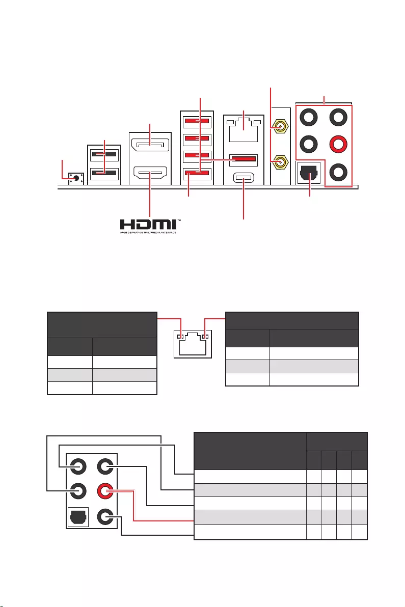
13
Panneau arrière Entrée/Sortie
Panneau arrière Entrée/Sortie
État Description
Éteint Pas de connexion
Jaune Connexion correcte
Clignote Activité en cours
État Description
Éteint 10 Mb/s
Vert 100/1000 Mb/s
Orange 2,5 Gb/s
39 pour la mise à jour du
BIOS avec Bouton Flash BIOS.
2,5 Gb/s LAN
Ports audio
Sortie S/PDIF
optique
DisplayPort
Connecteurs
USB 3.2 Gen 2
Bouton Flash
BIOS
Port Flash BIOS
USB 2.0
USB 3.2 Gen 2×2
Ports audio
2 4 6 8
Sortie centre/Caisson de basse
Entrée Microphone
(: connecté, Espace : vide)

14 Panneau arrière Entrée/Sortie
Après l’installation de Realtek Audio Console, vous pouvez l’utiliser pour modifier les
paramètres du son afin d’obtenir une meilleure expérience sonore.
Sélection du périphérique
audio pour en modifier les paramètres. Le symbole de coche indique le périphérique
sélectionné par défaut.
des effets acoustiques proposés pour les périphériques de sortie et d’entrée.
Volume principal
parleurs branchés sur le panneau avant ou derrière en ajustant la barre de volume.
État des prises Jack
connectés à votre ordinateur.
Paramètres du connecteur
Lorsqu’un périphérique est branché sur une prise audio, une fenêtre de dialogue
apparaît et vous demande de choisir le périphérique connecté que vous souhaitez
utiliser.
Chaque jack est réglé avec ses paramètres par défaut comme indiqué sur la page
suivante.
Important
le produit que vous avez acheté.
État des prises Jack
Paramètres du connecteur
Sélection du
périphérique
Volume principal
Amélioration d’application

15
Panneau arrière Entrée/Sortie
AUDIO INPUT
AUDIO INPUT
Rear Front
Side Center/
Subwoofer

16 Panneau arrière Entrée/Sortie
Installation des antennes
1. Vissez fermement les antennes aux connecteurs dédiés, comme illustré ici.
2. Orientez les antennes.
1
2
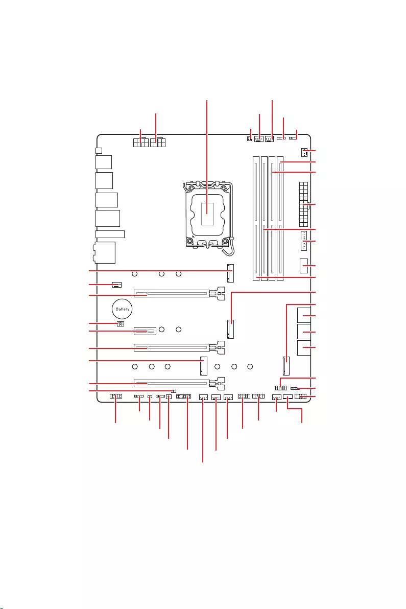
17
JUSB2
SYS_FAN5
SYS_FAN4
SYS_FAN3
SYS_FAN2
JBAT1
JTBT1
JTPM1
JRGB1
56
M2_3
JCI1
M2_1
SYS_FAN1
JDASH1
JUSB4
JUSB3
JUSB1
CPU_FAN1
SYS_FAN6
PUMP_FAN1
PCI_E1
PCI_E2
PCI_E3
PCI_E4
Scoket processeur
CPU_PWR1 JRAINBOW3JSMB1
CPU_PWR2 JRAINBOW2
JAUD1
JFP2
JRAINBOW1
JPWRLED1
LED_SW1
JFP1
ATX_PWR1
DIMMB1
DIMMB2
DIMMA1
M2_2
M2_4
DIMMA2

18
Important
Avant d’installer ou de retirer le processeur du socket, veillez à toujours débrancher
le câble d’alimentation de la prise électrique.
Veuillez garder le capot de protection du processeur après l’installation du
processeur. Selon les exigences de RMA (Return Merchandise Authorization), MSI
n’acceptera pas les cartes mère dont le capot de protection aura été retiré.
Lors de l’installation d’un processeur, n’oubliez pas d’installer un ventilateur pour
processeur. Un ventilateur de processeur est nécessaire pour protéger le processeur
contre la surchauffe et maintenir la stabilité du système.
démarrer votre système.
La surchauffe peut facilement endommager le processeur et la carte mère.
de pâte thermique (ou adhésif thermique) entre le processeur et le système de
refroidissement afin d’améliorer la dissipation de la chaleur.
Quand le processeur n’est pas installé, protégez toujours les broches du socket
CPU avec le couvercle dédié.
Si vous avez achetez un processeur indépendamment du ventilateur, veuillez vous
référer à la documentation dans le paquet du ventilateur pour plus d’informations
concernant l’installation.
Cette carte mère supporte l’overclocking. Néanmoins, veuillez vous assurer que vos
composants soient capables de tolérer l’overclocking. Prenez note que l’utilisation
pas les dommages et risques causés par les utilisations non prévues dans les
spécifications du produit.
Socket Processeur
Sur le socket LGA1700, vous
remarquerez quatre encoches et un
triangle doré servant d’indicateurs pour
placer le processeur dans la bonne
position. Le triangle doré correspond à
la broche 1 du processeur.
Distance entre le centre du CPU
et le slot DIMM le plus proche.
52,55 mm
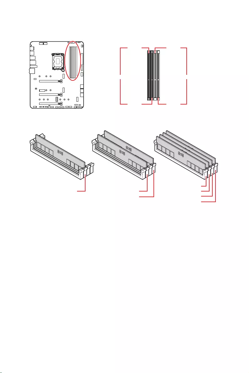
19
Slots DIMM
DIMMA1 DIMMB1
DIMMA2 DIMMB2
Installation recommandée de module mémoire
Important
Veillez à toujours insérer un module de mémoire dans l’emplacement en
premier.
d’installer les modules de mémoire du même type, du même nombre et de la même
densité.
Certaines mémoires peuvent fonctionner à une fréquence réduite par rapport à
la valeur indiquée lors de l’overclocking car la fréquence d’opération de mémoire
fonction pour régler la fréquence de mémoire si vous voulez faire
fonctionner la mémoire à la fréquence indiquée ou à une fréquence plus élevée.
Il est recommandé d’utiliser un système de refroidissement qui sera capable de
refroidir toutes les barrettes mémoire et d’offrir de bonnes performances lors d’un
overclocking.
La stabilité et la compatibilité du module de mémoire lors de l’overclocking
dépendent du processeur et des périphériques installés.
Veuillez vous référer au site www.msi.com pour plus d’informations sur la mémoire
compatible.
DIMMA2 DIMMA2
DIMMB2
DIMMA1
DIMMA2
DIMMB1
DIMMB2
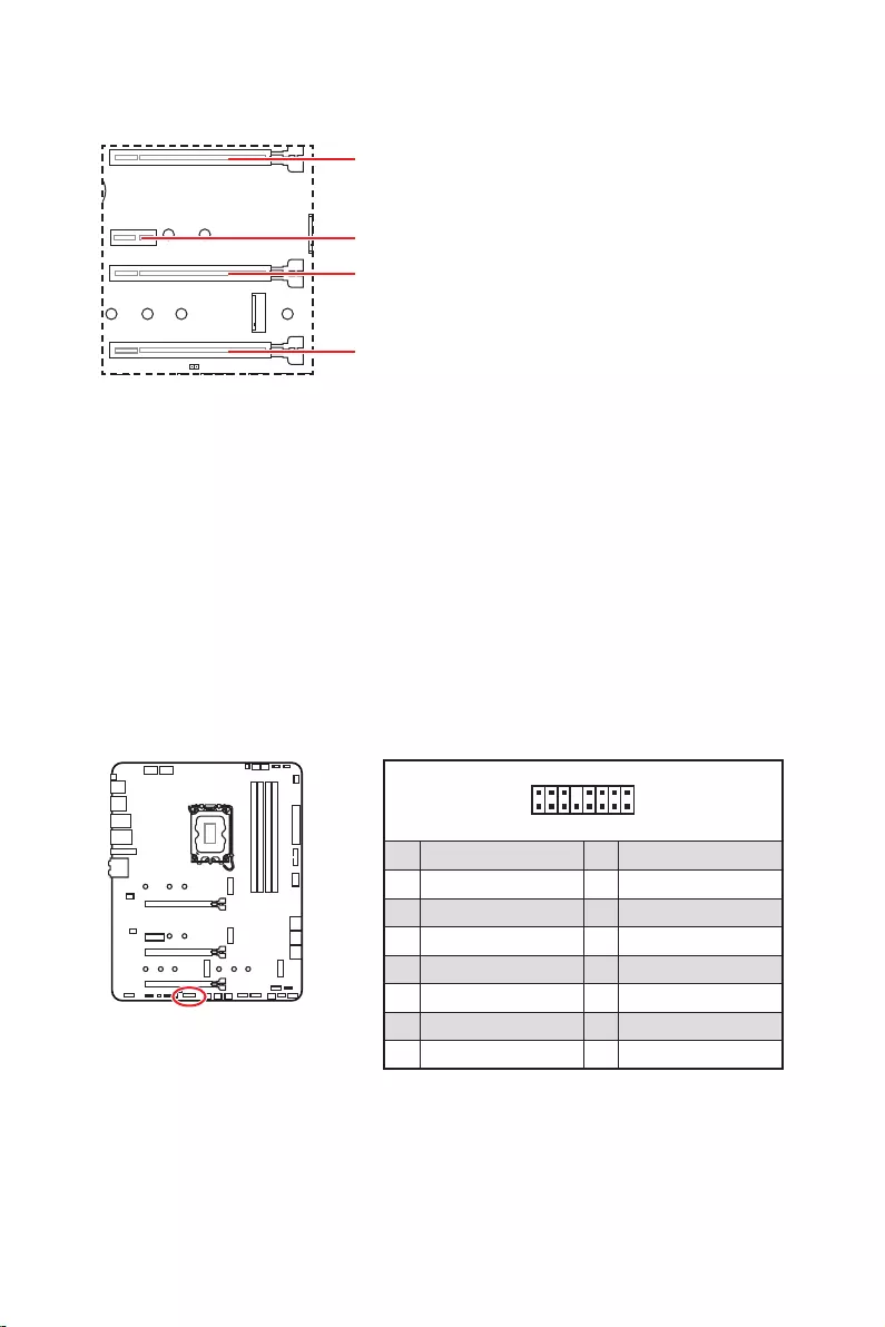
20
: PCIe 5.0 x16 (depuis CPU)
: PCIe 3.0 x1 (depuis chipset Z690)
: PCIe 3.0 x4 (depuis chipset Z690)
: PCIe 3.0 x4 (depuis chipset Z690)
Important
Si vous installez une carte graphique lourde, il vous faut utiliser un outil comme
la barre de support MSI Gaming Series pour supporter son poids et pour éviter la
déformation du slot.
Si vous choisissez d’installer une seule carte d’extension PCIe x16, nous vous
recommandons d’utiliser le slot pour profiter de performances optimales.
Veillez à toujours mettre l’ordinateur hors tension et à débrancher le cordon
documentation des cartes pour vérifier si un composant ou un logiciel doit être
modifié.
Ce connecteur vous permet de relier une carte additionnelle Thunderbolt E/S.
1
2 16
15
1 TBT_Force_PWR 2 TBT_S0IX_Entry_REQ
3 TBT_CIO_Plug_Event# 4 TBT_S0IX_Entry_ACK
5 SLP_S3#_TBT 6 TBT_PSON_Override_N
7 SLP_S5#_TBT 8 No pin
9 Ground 10 SMBCLK_VSB
11 DG_PEWake 12 SMBDATA_VSB
13 TBT_RTD3_PWR_EN 14 Ground
15 TBT_Card_DET_R# 16 PD_IRQ#

21
M2_1
M2_2
M2_4
M2_3
Important
La technologie Intel® RST supporte uniquement
un SSD M.2 PCIe avec une mémoire UEFI ROM.
Les slots M2_2~4 supportent Intel® Optane™
Memory.
Installation du module M.2
1. Desserrez les vis de la plaque M.2 SHIELD FROZR.
2. Retirez la plaque M.2 SHIELD FROZR et retirez le film de protection du pad
thermique.
2
2
2
2
1
1
1
1
11
1
M2_2
M2_3
M2_1
M2_4

22
30º30º
5
6
6
6
66 6
6
4
3
3. Si aucun clip EZ M.2 n’est installé, veuillez installer le kit de clips EZ M.2 fourni
dans le slot M.2 selon la longueur du SSD.
4. Insérez votre SSD M.2 dans le slot M.2 à un angle de 30 degrés.
5. Faites pivoter le clip EZ M.2 pour fixer le SSD M.2.
6.
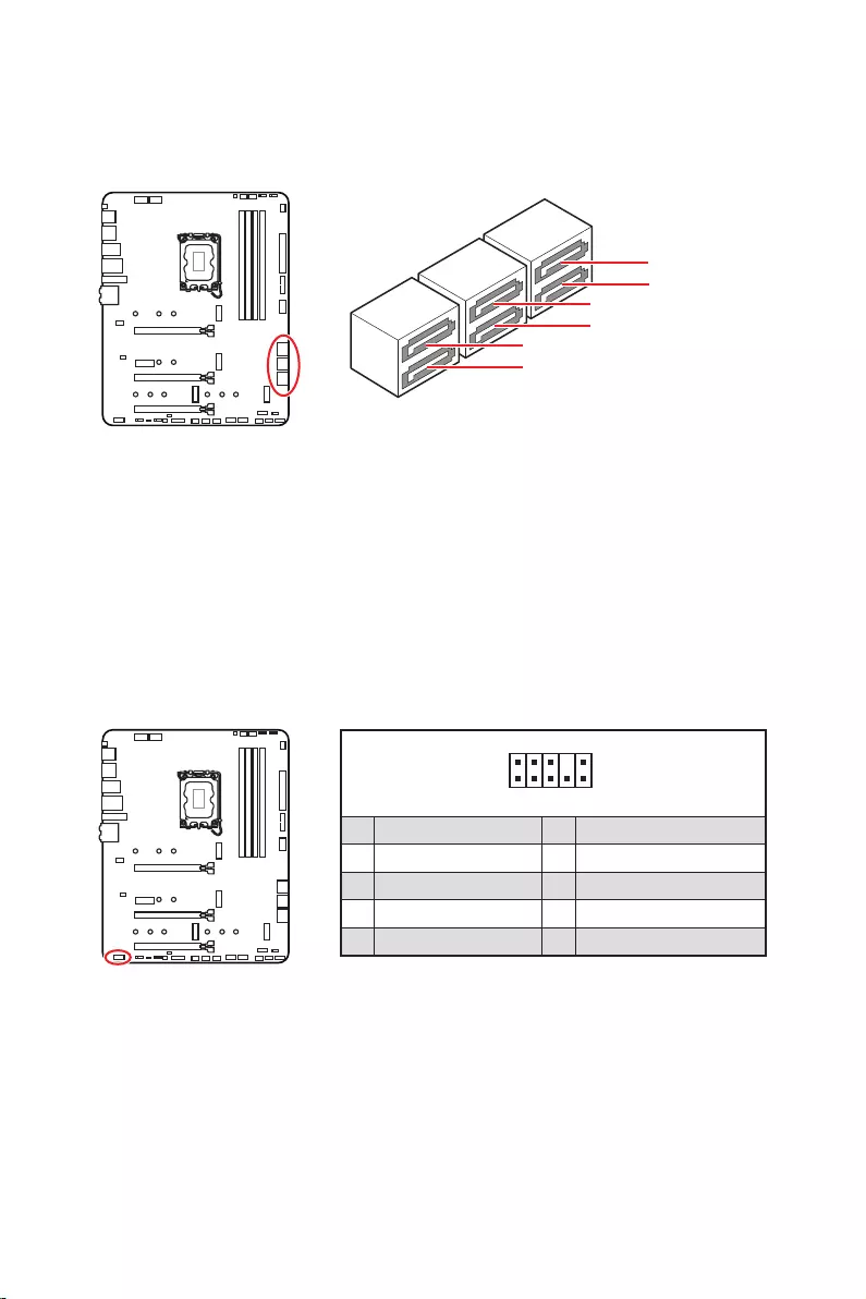
23
Ces connecteurs utilisent une interface SATA 6 Gb/s. Chaque connecteur peut être
relié à un appareil SATA.
SATAA
SATA7
SATA5
SATAB
SATA8
SATA6
Important
Veuillez ne pas plier les câbles SATA à 90° car cela pourrait entraîner une perte de
données pendant la transmission.
Les câbles SATA disposent de prises identiques sur chaque côté. Néanmoins, il est
recommandé de connecter la prise plate sur la carte mère pour un gain d’espace.
Ce connecteur se lie aux jacks audio du panneau avant.
1
2 10
9
1 MIC L 2 Ground
3 MIC R 4 NC
5 Head Phone R 6 MIC Detection
7 SENSE_SEND 8 No Pin
9 Head Phone L 10 Head Phone Detection

24
Ces connecteurs se lient aux interrupteurs et indicateurs LED du panneau avant.
1
2 10
9
+
+
+
+
Power LED
HDD LED Reset Switch
Reserved
Power Switch
JFP1
1 HDD LED + 2 Power LED +
3 4
5 Reset Switch 6 Power Switch
7 Reset Switch 8 Power Switch
9 Reserved 10 No Pin
1
JFP2
+
+
Speaker
Buzzer
1 2 Buzzer +
3 4 Speaker +

25
24
131
12
ATX_PWR1
1 +3.3V 13 +3.3V
2 +3.3V 14
3 Ground 15 Ground
4 +5V 16
5 Ground 17 Ground
6 +5V 18 Ground
7 Ground 19 Ground
8 PWR OK 20 Res
9 5VSB 21 +5V
10 +12V 22 +5V
11 +12V 23 +5V
12 +3.3V 24 Ground
5
4 1
8CPU_PWR1~2
1 Ground 5 +12V
2 Ground 6 +12V
3 Ground 7 +12V
4 Ground 8 +12V
Important
Veuillez vous assurer que tous les câbles d’alimentation sont branchés aux
connecteurs adéquats afin de garantir une opération stable de la carte mère.
Ces connecteurs vous permettent de relier une alimentation ATX.

26
sur le panneau avant. Pour plus de sécurité, ce connecteur a été conçu pour offrir une
dans le bon sens.
Ce connecteur vous permet de relier un port USB 3.2 Gen 1 5 Gb/s sur le panneau
avant.
Important
Notez que les câbles d’alimentation et de terre doivent être branchés correctement
afin d’éviter d’endommager la carte.
1
10 11
20
1 Power 11 USB2.0+
2 USB3_RX_DN 12
3 USB3_RX_DP 13 Ground
4 Ground 14 USB3_TX_C_DP
5 USB3_TX_C_DN 15 USB3_TX_C_DN
6 USB3_TX_C_DP 16 Ground
7 Ground 17 USB3_RX_DP
8 18 USB3_RX_DN
9 USB2.0+ 19 Power
10 Ground 20 No Pin
JUSB4
sur le panneau
avant

27
Ces connecteurs vous permettent de relier des ports USB 2.0 sur le panneau avant.
1
2 10
9
1 VCC 2 VCC
3 4
5 USB0+ 6 USB1+
7 Ground 8 Ground
9 No Pin 10 NC
Important
Notez que les broches VCC et Terre doivent être branchées correctement afin
d’éviter tout dommage sur la carte mère.
Pour recharger votre iPad, iPhone et iPod par l’intermédiaire d’un port USB, veuillez
installer l’utilitaire MSI® Center.
1
2 12
11
1 SPI Power 2 SPI Chip Select
3
Master In Slave Out (SPI Data)
4
Master Out Slave In (SPI Data)
5 Reserved 6 SPI Clock
7 Ground 8 SPI Reset
9 Reserved 10 No Pin
11 Reserved 12 Interrupt Request
Ce connecteur est relié à un module TPM (Trusted Platform Module). Veuillez vous
référer au manuel du module TPM pour plus d’informations.
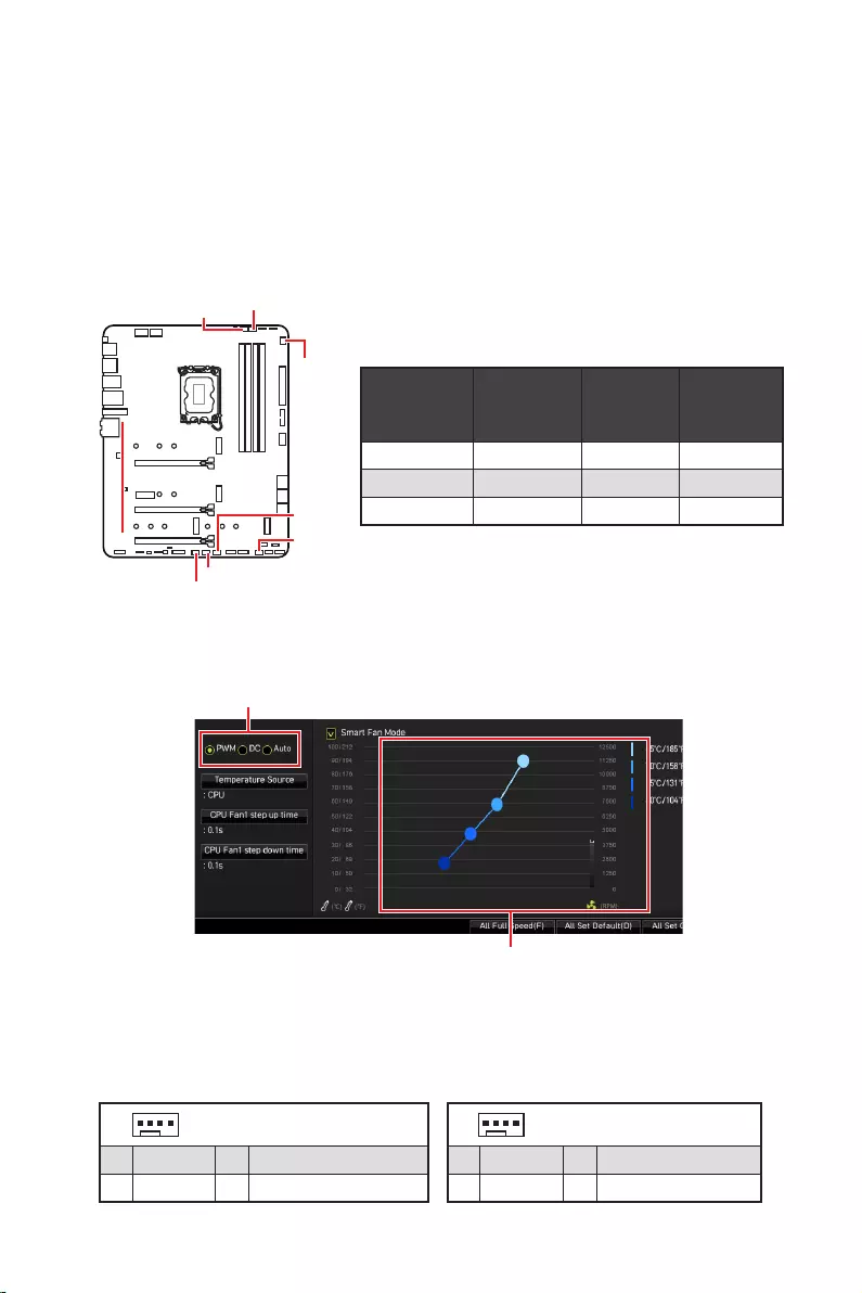
28
ventilateur
Les connecteurs de ventilateur peuvent être utilisés en mode PWM (Pulse Width
Modulation) et en mode DC. En mode PWM, les connecteurs fournissent une sortie
de 12 V constante et ajustent la vitesse du ventilateur avec un signal de contrôle de
vitesse. En mode DC, les connecteurs contrôlent la vitesse du ventilateur en modifiant
la tension. Le mode automatique détectera automatiquement le type de ventilateur
connecteur de ventilateur en mode PWM ou mode DC.
Vous pouvez alterner entre le mode PWM et le mode DC et ajuster la vitesse du
ventilateur dans .
Choisissez le mode PWM ou le mode
Important
Veuillez vous assurer que les ventilateurs fonctionnent correctement après avoir
basculé entre les modes PWM et DC.
Il y a des points de gradient de la vitesse du ventilateur qui
vous permet d’ajuster la vitesse du ventilateur par rapport à la
température du processeur.
Définition des broches des connecteurs de ventilateur
Mode
ventilateur
par défaut
maximum Puissance
maximum
CPU_FAN1 Mode Auto 2 A 24 W
PUMP_FAN1 Mode PWM 3 A 36 W
SYS_FAN1~6 Mode DC 1 A 12 W
1 Définition des broches en mode PWM
1 Ground 2 +12V
3 Sense 4 Speed Control Signal
1
1 Ground 2 Voltage Control
3 Sense 4 NC
SYS_FAN1
SYS_FAN3
SYS_FAN5
SYS_FAN4
PUMP_FAN1
CPU_FAN1
SYS_FAN2
SYS_FAN6

29
Ce connecteur est relié à un câble d’interrupteur intrusion châssis.
Normal
(défaut) Commencer l’activité
instrusion châssis
1. Reliez le connecteur à l’interrupteur ou au capteur d’intrusion châssis situé
sur le boîtier du PC.
2. Fermez le couvercle du boîtier.
3. Allez dans
.
4. Réglez sur .
5. Appuyez sur F10 pour sauvegarder et quitter. Ensuite appuyez sur la touche Enter
pour choisir .
6. Désormais, si le boîtier du PC est ouvert quand l’ordinateur est allumé, vous
recevrez un message d’avertissement à l’écran.
1. Allez dans
.
2. Réglez sur .
3. Appuyez sur F10 pour sauvegarder et quitter. Ensuite appuyez sur la touche Enter
pour choisir .
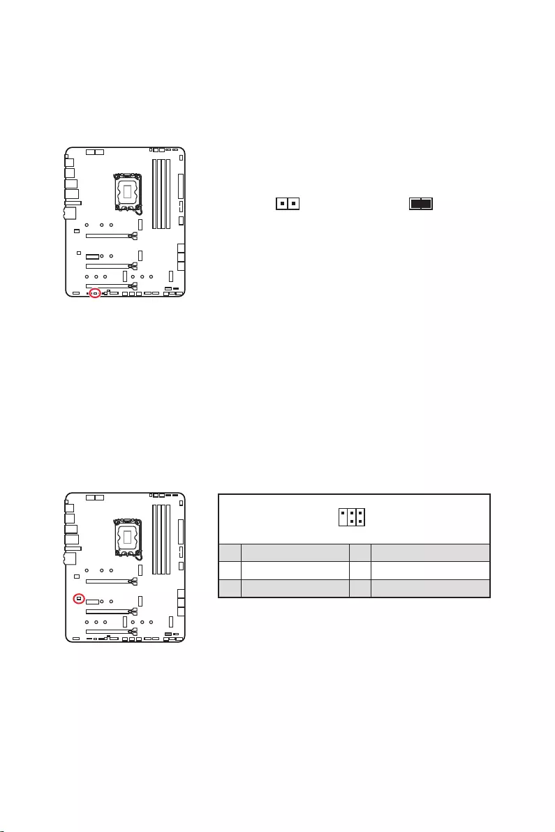
30
Une mémoire CMOS est intégrée et est alimentée en externe par une batterie située
sur la carte mère afin de conserver les données de configuration système. Si vous
souhaitez nettoyer la configuration du système, réglez le cavalier pour effacer la
mémoire CMOS.
Conserver
les données
(défaut)
Effacer le CMOS/
Réinitialiser le BIOS
1. Éteignez l’ordinateur et débranchez le câble d’alimentation de la prise électrique.
2. Utilisez un couvercle de cavalier pour fermer pendant 5 à 10 secondes.
3. Enlevez le couvercle de cavalier du .
4.
Ce connecteur est utilisé pour connecter un contrôleur de réglage (selon modèle).
1
2 6
5
1 No Pin 2 NC
3 MCU_SMB_SCL_M 4 MCU_SMB_SDA_M
5 VCC5 6 Ground
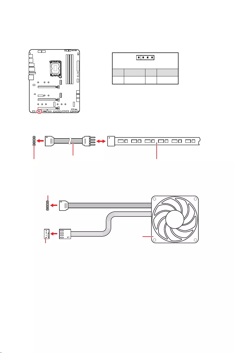
31
Important
Le connecteur JRGB supporte des rubans LED RGB (12 V/G/R/B) de type 5050 d’une
longueur de 2 mètres maximum avec une puissance nominale maximale de 3 A (12 V).
Avant d’installer ou de retirer le ruban LED RGB, veillez à toujours éteindre
l’alimentation et à débrancher le câble d’alimentation de la prise électrique.
Veuillez utiliser un logiciel MSI dédié pour contrôler le ruban d’extension LED.
Le connecteur JRGB vous permet de connecter un ruban LED RGB de type 5050 12 V.
1
GRB
Connecteur JRGB Câble d’extension JRGB Ruban LED RGB de type 5050, sortie 12 V
1
1 +12V 2 G
3 R 4 B
1
1
GRB
Connecteur JRGB
Connecteur de ventilateur système
Ventilateur LED RGB
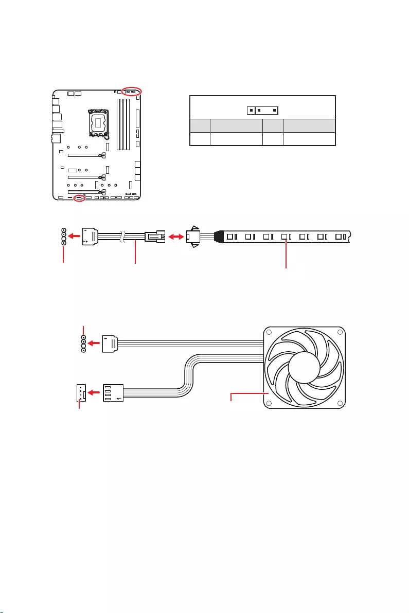
32
1
1
1
D
+5V
Faites attention à bien connecter le bon type de ruban LED. Le connecteur JRGB et le
connecteur JRAINBOW fournissent des tensions différentes. La connexion d’un ruban
LED 5 V au connecteur JRGB peut endommager le ruban.
Important
Le connecteur JRAINBOW supporte jusqu’à des rubans 75 LEDs WS2812B
adressables individuellement (5 V/Data/Ground) avec une puissance nominale
maximale de 3 A (5 V). Dans le cas d’une luminosité de 20 %, le connecteur supporte
jusqu’à 200 LED.
Avant d’installer ou de retirer le ruban LED RGB, veillez à toujours éteindre
l’alimentation et à débrancher le câble d’alimentation de la prise électrique.
Veuillez utiliser un logiciel MSI dédié pour contrôler le ruban d’extension LED.
Le connecteur JRAINBOW vous permet de connecter un ruban à LED RGB WS2812B
adressable individuellement 5 V.
Connecteur
JRAINBOW
Connecteur JRAINBOW
Connecteur de ventilateur système
Câble d’extension
JRAINBOW Ruban LED RGB WS2812B
adressable individuellement,
sortie 5 V
1
1 +5V 2 Data
3 No Pin 4 Ground
Ventilateur LED RGB adressable

33
Ces LEDs indiquent l’état de débogage de la carte mère.
Cet interrupteur est utilisé pour allumer et éteindre toutes les LED de la carte mère.
LED_SW1
LED_OFF LED_ON
(Défaut)
Ce connecteur est utilisé par les revendeurs pour faire une démonstration des effets
de lumière des indicateurs LED.
son initialisation a échoué.
détectée ou que son initialisation a échoué.
son initialisation a échoué.
n’est pas détecté ou que son initialisation a
échoué.

34
Veuillez vous référer au site www.msi.com pour télécharger et mettre à jour les
derniers utilitaires et pilotes.
1. Allumez l’ordinateur.
2. Insérez le disque ou la clé USB d’installation de Windows 10/ Windows 11 dans
votre ordinateur.
3. Appuyez sur le bouton du boîtier de l’ordinateur.
4. Appuyez sur la touche F11
entrer dans le menu de démarrage.
5. Choisissez le disque ou la clé USB d’installation de Windows 10/ Windows 11 dans
le menu de démarrage.
6. Appuyez sur n’importe quelle touche lorsqu’apparaît le message
.
7. Suivez les instructions à l’écran pour installer Windows 10/ Windows 11.
Installer les pilotes
1. Allumez l’ordinateur sous Windows 10/ Windows 11.
2. Insérez la clé USB MSI® dans le port USB.
3. Cliquez sur la fenêtre popup
, puis choisissez
pour ouvrir l’outil d’installation. Si vous désactivez la fonction
AutoPlay dans le panneau de configuration Windows, vous pouvez quand même
exécuter manuellement DVDSetup.exe à partir du chemin d’accès depuis la racine
de la clé USB MSI.
4. L’outil d’installation trouvera et listera tous les pilotes dont vous avez besoin dans
l’onglet .
5. Cliquez sur le bouton dans le coin inférieur droit de la fenêtre.
6. L’installation des pilotes commence. Une fois terminée, il vous sera demandé de
redémarrer.
7. Cliquez sur le bouton pour terminer.
8. Redémarrez votre ordinateur.

35
MSI Center est une application qui vous aide à optimiser facilement les paramètres
de jeu et à utiliser les logiciels de création de contenu de manière intuitive. Elle vous
permet également de contrôler et de synchroniser les effets de lumière LED sur les
PC et autres produits MSI. Avec MSI Center, vous pouvez personnaliser les modes
selon vos envies, surveiller les performances du système et régler la vitesse du
ventilateur.
Si vous souhaitez en savoir plus sur MSI Center, veuillez vous référer
au fichier
http://download.msi.com/manual/mb/MSICENTER.pdf
ou scannez le code QR pour y accéder.
Important
Les fonctions peuvent varier en fonction du produit que vous possédez.

36
Le BIOS UEFI de MSI est compatible avec l’architecture UEFI (Unified Extensible
Firmware Interface). Le BIOS UEFI présente de nombreuses nouvelles fonctionnalités
et avantages qui ne sont pas proposés par le BIOS traditionnel. Le BIOS UEFI est ainsi
voué à totalement remplacer le BIOS traditionnel à l’avenir. Le BIOS UEFI de MSI
utilise UEFI comme mode de démarrage par défaut pour profiter au maximum des
capacités du nouveau chipset.
Important
Dans ce guide d’utilisation, le terme BIOS se réfère au BIOS UEFI, sauf indication
contraire.
enregistrer le processus d’autotest du BIOS. Il élimine également le temps à attendre
pour passer en mode CSM pendant le POST.
Prend en charge des partitions de disque dur supérieures à 2 To.
Prend en charge plus de 4 partitions principales avec une table de partition GUID
(GPT).
Prend en charge un nombre illimité de partitions.
appareils peuvent ne pas fournir de compatibilité descendante.
d’exploitation pour s’assurer qu’aucun malware ne perturbe le processus de
démarrage.
système d’exploitation Windows 10/ Windows 11 64 bits.
message d’avertissement apparaît si
.
Important
Nous vous recommandons de remplacer votre carte graphique par un modèle
compatible GOP/UEFI ou d’utiliser la puce graphique intégrée à votre processeur pour
profiter d’un fonctionnement normal.
1. Allumez votre ordinateur.
2. Pendant le démarrage, lorsqu’apparaît le message
sur l’écran, veuillez appuyer sur la touche Suppr.
3. Après être entré dans le BIOS, vous pouvez vérifier le en haut de
l’écran.

37
Les réglages par défaut fournissent une performance optimale pour la stabilité du
système en conditions normales. Veillez à
pour éviter d’endommager le système ou tout problème au démarrage, sauf si vous
êtes familier avec le BIOS.
Important
Le BIOS est constamment mis à jour afin d’offrir de meilleures performances
système. Par conséquent, la description peut différer selon la version du BIOS utilisée
et n’est donc donnée qu’à titre de référence. Vous pouvez aussi vous référer à l’onglet
pour obtenir la description des fonctions du BIOS.
Les écrans, les options et les paramètres du BIOS peuvent varier selon votre
système.
Pendant le démarrage, lorsqu’apparaît le message
sur l’écran, veuillez appuyer sur la touche Suppr.
F1 : Liste d’aide générale
F2 : Ajouter ou supprimer un élément favori
F3 : Entrer dans le menu Favoris
F4 : Entrer dans le menu caractéristiques du processeur
F5
F6 : Charger les réglages par défaut
F7 : Alterner entre le mode avancé et le mode simplifié
F8 : Charger le profil d’overclocking
F9 : Sauvegarder le profil d’overclocking
F10 : Sauvegarder les modifications et réinitialiser*
F12 : Prendre une capture d’écran et la conserver dans la clé USB (au format FAT/
FAT32 uniquement)
: Entrer dans la page de recherche
* Lorsque vous appuyez sur F10, une fenêtre de confirmation apparaît et fournit
l’information de modification. Choisissez entre Oui et Non pour confirmer.
Si vous souhaitez en savoir plus sur la configuration du BIOS, veuillez
vous référer au fichier
http://download.msi.com/manual/mb/Intel600BIOSfr.pdf
ou scannez le code QR pour y accéder.

38
Il se peut que vous ayez besoin de récupérer les réglages BIOS par défaut pour
résoudre des problèmes. Pour réinitialiser les réglages du BIOS, veuillez suivre l’une
des méthodes suivantes :
Allez dans le BIOS et appuyez sur F6 pour charger les réglages par défaut.
sur la carte mère.
Important
vous référer à la section cavalier pour en savoir plus sur la réinitialisation
du BIOS.
Avant la mise à jour :
Veuillez télécharger la dernière version du BIOS compatible à votre carte mère sur le
site MSI. Ensuite, veuillez sauvegarder le profil BIOS sur la clé USB.
Mettre le BIOS à jour :
1.
si votre carte mère ne possède pas ce commutateur.
2. Insérez la clé USB contenant le profil au port USB.
3. Veuillez vous référer aux méthodes suivantes pour passer en mode flash.
Redémarrez et appuyez sur la touche pendant le processus de POST et
cliquez sur pour redémarrer le système.
Redémarrez et appuyez sur la touche Del pendant le processus de POST pour
entrer dans le BIOS. Cliquez sur le bouton et cliquez sur pour
redémarrer le système.
4. Choisissez un profil BIOS pour commencer la mise à jour du BIOS.
5. Lorsque vous y êtes invité, cliquez sur pour lancer la restauration du BIOS.
6. Une fois la mise à jour terminée, le système redémarrera automatiquement.

39
Avant la mise à jour :
correctement connecté à internet.
Veuillez désactiver tous les autres logiciels d’application avant de mettre à jour le
BIOS.
Mettre le BIOS à jour :
1. Installez et lancez MSI Center et accédez à la page Support.
2. Choisissez et cliquez sur le bouton .
3. Choisissez le profil BIOS et cliquez sur le bouton Installer.
4. Le rappel d’installation apparaît. Cliquez ensuite sur le bouton Installer.
5. Le système redémarrera automatiquement pour la mise à jour du BIOS.
6. Une fois la mise à jour terminée, le système redémarrera automatiquement.
1. Veuillez télécharger la dernière version du BIOS compatible à votre carte mère
sur le site MSI®.
2.
3. Connectez l’alimentation aux connecteurs et . (Pas besoin
d’installer le processeur et la mémoire.)
4. Branchez la clé USB contenant le fichier MSI.ROM au situé sur le
panneau arrière Entrée/Sortie.
5. Appuyez sur le bouton pour flasher le BIOS. Le voyant LED
commencera alors à clignoter.
6. Une fois le processus terminé, la LED s’éteint.


1
……………………………………………………. 3
……………………….. 4
…………………………………………………………………………………….. 4
………………………………………………………………….. 5
……………………………………………………………………………….. 12
……………………………………………………. 13
………………………………………………. 13
…………………………………………………………………… 13
Realtek Audio Console …………………………………………………………………………….. 14
…………………………………………………………… 17
………………………………………………………………………………. 18
…………………………………………………………………………………………… 19
…………………………………………………………. 20
………………….. 20
………………………………………………………………. 21
………………………………………………. 23
…………………………………………………… 23
…………………………………………………… 24
…………………………………………… 25
………………………………………………………. 26
………………………………………………………………….. 26
…………………………………………………………………….. 27
……………………………………………………………………. 27
……………….. 28
………………………………………………….. 29
………………………………. 30
…………………………………………………. 30
…………………………………………………………………………. 31
……………………………………………. 32
……………………………………………………………………….. 33
………………………………………………………………………….. 33
……………………………… 33
…………………………………………. 33
…………………………………………………… 34
…………………………………………………………. 34

2
……………………………………………………………………………… 34
MSI Center ……………………………………………………………………………………………… 34
………………………………………………………………………………………………. 35
………………………………………………………………………………………. 36
……………………………………………………………………………. 36
……………………………………………………………….. 36
…………………………………………………………………………………………….. 37
……………………………………………………………………………………. 37

3

4

5
Intel® Z690
JEDEC
® XMP 3.0 OC
Dual Controller
/**
/**

6
Z690)
Z690)
Z690)
PCIe
Realtek® ALC4080

7
6E
Windows 11.

8
NUVOTON NCT6687D

9
UEFI AMI BIOS
ACPI 6.4, SMBIOS 3.4
MSI Center
Intel® Extreme Tuning Utility
MSI APP Player (BlueStacks)
Open Broadcaster Software (OBS)
Google Chrome™, Google Toolbar, Google Drive
Norton™ Internet Security Solution
Gaming Mode
Smart Priority
Gaming Highlight
LAN Manager
Mystic Light
Ambient Devices
Frozr AI Cooling
User Scenario
True Color
Live Update
Hardware Monitoring
Super Charger
Speed Up
Smart Image Finder
MSI Companion

10
Audio Boost 5
2.5G LAN
LAN Manager
Intel® WiFi
All Aluminum Design
Extended Heatsink Design
M.2 Shield Frozr
7W/mK MOSFET thermal pad
Choke thermal pad
Pump Fan
Smart Fan Control
Mystic Light
Mystic Light Extension (RAINBOW/RGB)
Mystic Light SYNC
Ambient Devices Support

11
Lightning Gen 4 M.2
Multi GPU – CrossFire Technology
Memory Boost
Core Boost
Game Boost
Lightning USB 20G
USB 3.2 Gen 2 10G
Dual CPU Power
Server PCB
2oz Copper thickened PCB
MSI Center
Click BIOS 5
EZ M.2 Clip
Frozr AI Cooling
EZ LED Control
EZ DEBUG LED
App player
Tile
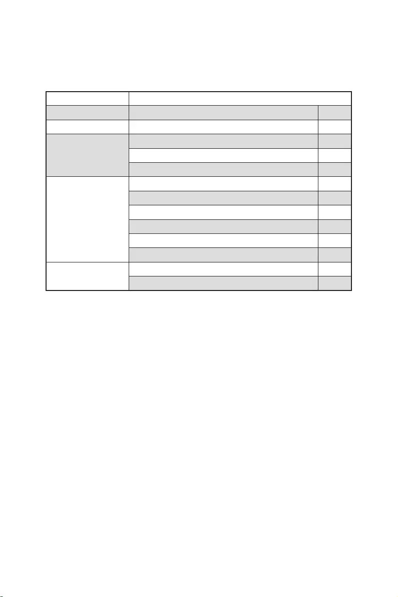
12
MPG Z690 EDGE WIFI
1
1
1
1
1
1
1
2
1
1
1
1
1

13
2468
DisplayPort
USB 3.2 Gen 2
Flash BIOS
USB 2.0
USB 3.2 Gen 2×2
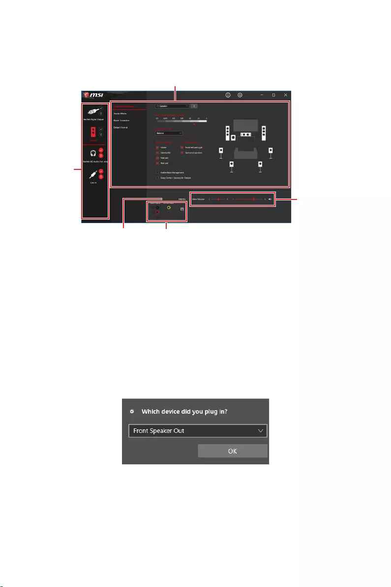
14
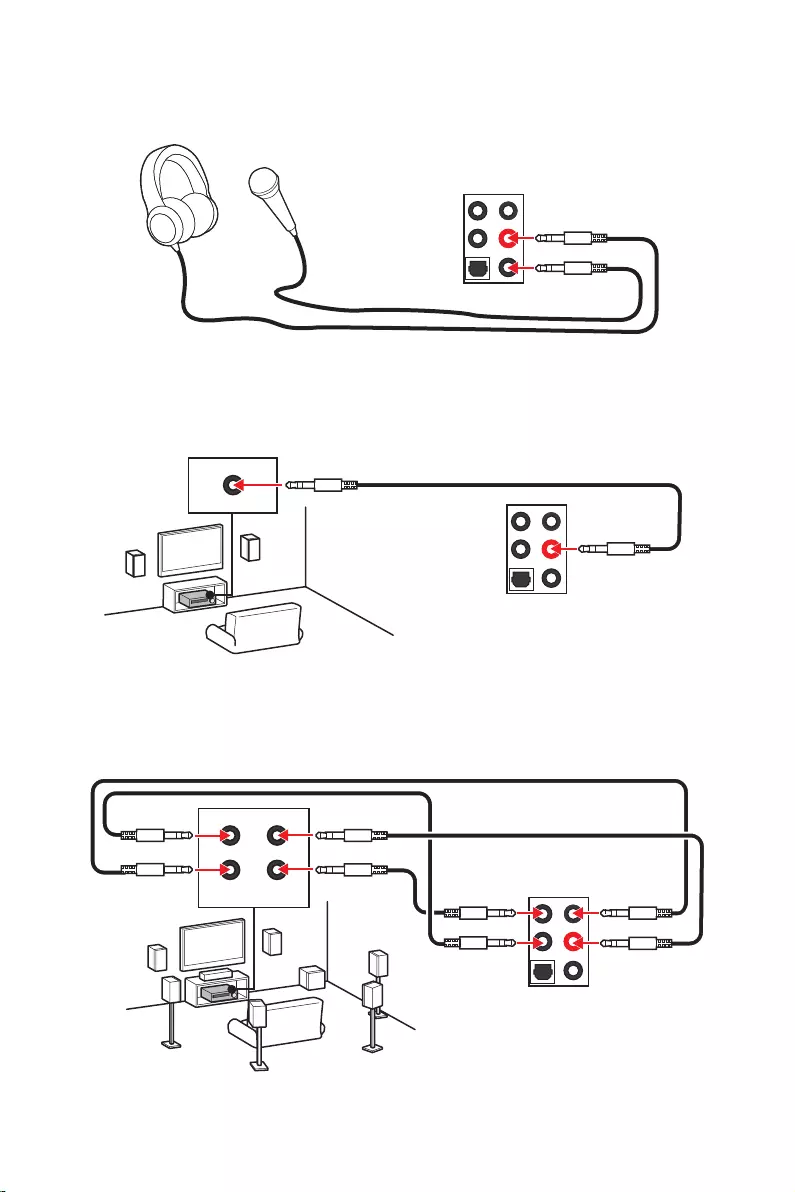
15
AUDIO INPUT
AUDIO INPUT
Rear Front
Side Center/
Subwoofer

16
1.
2.
1
2

17
JUSB2
SYS_FAN5
SYS_FAN4
SYS_FAN3
SYS_FAN2
JBAT1
JTBT1
JTPM1
JRGB1
56
M2_3
JCI1
M2_1
SYS_FAN1
JDASH1
JUSB4
JUSB3
JUSB1
CPU_FAN1
SYS_FAN6
PUMP_FAN1
PCI_E1
PCI_E2
PCI_E3
PCI_E4
CPU_PWR1 JRAINBOW3JSMB1
CPU_PWR2 JRAINBOW2
JAUD1
JFP2
JRAINBOW1
JPWRLED1
LED_SW1
JFP1
ATX_PWR1
DIMMB1
DIMMB2
DIMMA1
M2_2
M2_4
DIMMA2

18

19
.
DIMMA1 DIMMB1
DIMMA2 DIMMB2
DIMMA2 DIMMA2
DIMMB2
DIMMA1
DIMMA2
DIMMB1
DIMMB2
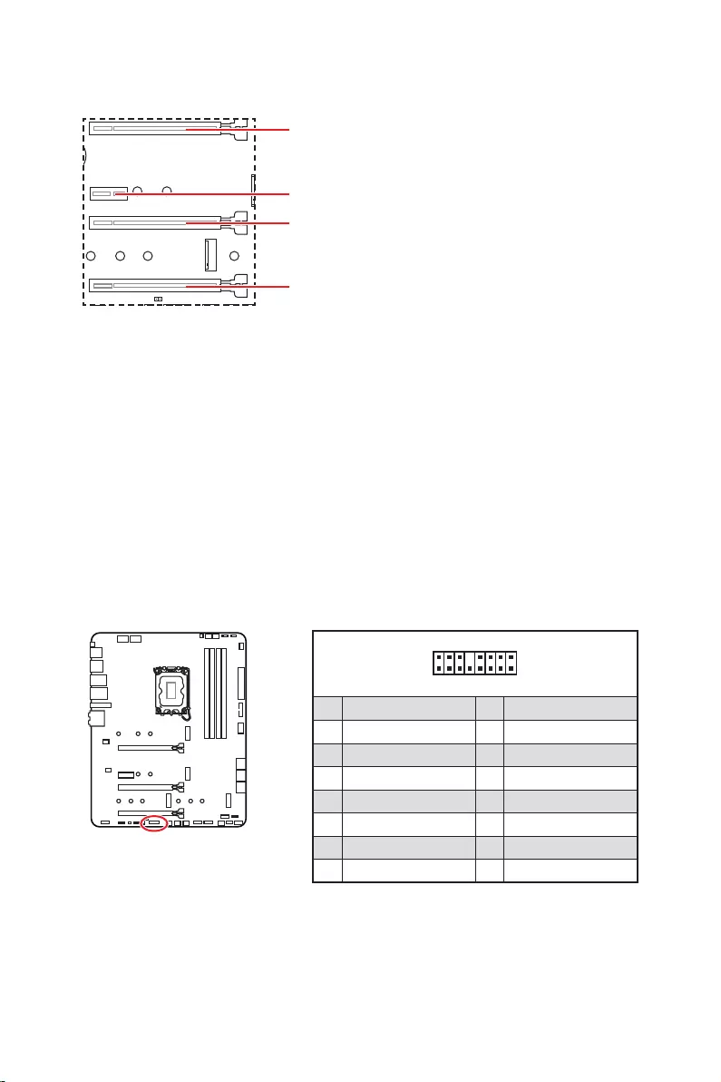
20
: PCIe 3.0 x4 (
.
Thunderbolt.
1
2 16
15
1 TBT_Force_PWR 2 TBT_S0IX_Entry_REQ
3 TBT_CIO_Plug_Event# 4 TBT_S0IX_Entry_ACK
5 SLP_S3#_TBT 6 TBT_PSON_Override_N
7 SLP_S5#_TBT 8 No pin
9 Ground 10 SMBCLK_VSB
11 DG_PEWake 12 SMBDATA_VSB
13 TBT_RTD3_PWR_EN 14 Ground
15 TBT_Card_DET_R# 16 PD_IRQ#

21
M2_1
M2_2
M2_4
M2_3
Optane™.
1.
2.
2
2
2
2
1
1
1
1
11
1
M2_2
M2_3
M2_1
M2_4

22
30º30º
5
6
6
6
66 6
6
4
3
3.
4.
5.
6.

23
SATAA
SATA7
SATA5
SATAB
SATA8
SATA6
1
2 10
9
1 MIC L 2 Ground
3 MIC R 4 NC
5 Head Phone R 6 MIC Detection
7 SENSE_SEND 8 No Pin
9 Head Phone L 10 Head Phone Detection
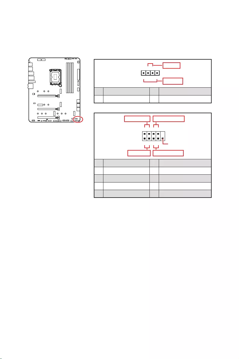
24
1
2 10
9
+
+
+
+
Power LED
HDD LED Reset Switch
Reserved
Power Switch
JFP1
1 HDD LED + 2 Power LED +
3 4
5 Reset Switch 6 Power Switch
7 Reset Switch 8 Power Switch
9 Reserved 10 No Pin
1
JFP2
+
+
Speaker
Buzzer
1 2 Buzzer +
3 4 Speaker +

25
24
131
12
ATX_PWR1
1 +3.3V 13 +3.3V
2 +3.3V 14
3 Ground 15 Ground
4 +5V 16
5 Ground 17 Ground
6 +5V 18 Ground
7 Ground 19 Ground
8 PWR OK 20 Res
9 5VSB 21 +5V
10 +12V 22 +5V
11 +12V 23 +5V
12 +3.3V 24 Ground
5
4 1
8CPU_PWR1~2
1 Ground 5 +12V
2 Ground 6 +12V
3 Ground 7 +12V
4 Ground 8 +12V
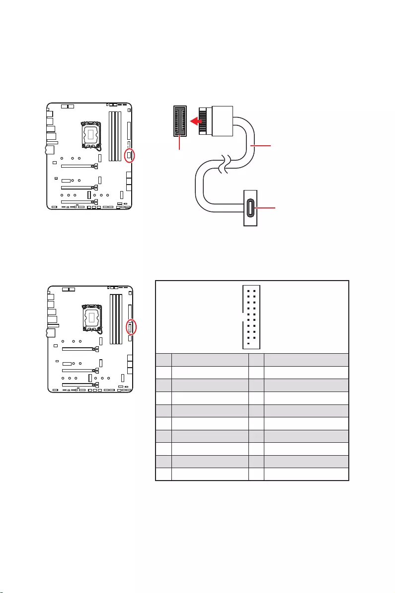
26
1
10 11
20
1 Power 11 USB2.0+
2 USB3_RX_DN 12
3 USB3_RX_DP 13 Ground
4 Ground 14 USB3_TX_C_DP
5 USB3_TX_C_DN 15 USB3_TX_C_DN
6 USB3_TX_C_DP 16 Ground
7 Ground 17 USB3_RX_DP
8 18 USB3_RX_DN
9 USB2.0+ 19 Power
10 Ground 20 No Pin
JUSB4
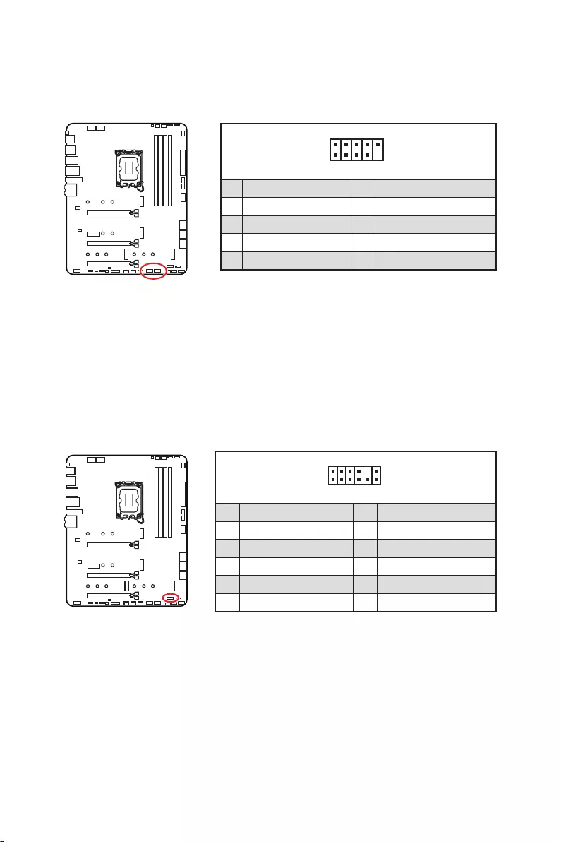
27
1
2 10
9
1 VCC 2 VCC
3 4
5 USB0+ 6 USB1+
7 Ground 8 Ground
9 No Pin 10 NC
1
2 12
11
1 SPI Power 2 SPI Chip Select
3
Master In Slave Out (SPI Data)
4
Master Out Slave In (SPI Data)
5 Reserved 6 SPI Clock
7 Ground 8 SPI Reset
9 Reserved 10 No Pin
11 Reserved 12 Interrupt Request

28
PWM
CPU_FAN1
2A
PUMP_FAN1
SYS_FAN1~6
1
1 Ground 2 +12V
3 Sense 4 Speed Control Signal
1
1 Ground 2 Voltage Control
3 Sense 4 NC
SYS_FAN1
SYS_FAN3
SYS_FAN5
SYS_FAN4
PUMP_FAN1
CPU_FAN1
SYS_FAN2
SYS_FAN6

29
1. .
2.
3. .
4. Enabled.
5. F10
EnterYes.
6.
1. .
2. , Reset.
3. F10
EnterYes.
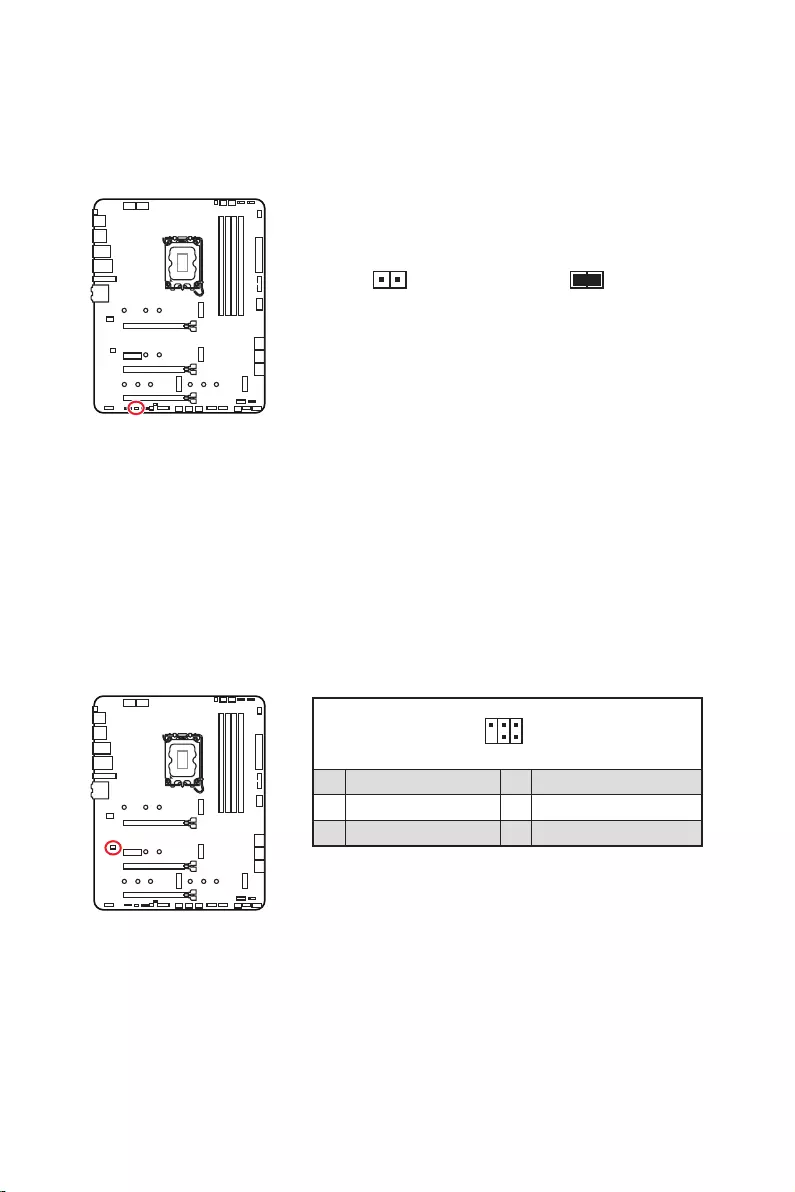
30
1.
2.
3. .
4.
1
2 6
5
1 No Pin 2 NC
3 MCU_SMB_SCL_M 4 MCU_SMB_SDA_M
5 VCC5 6 Ground

31
1
GRB
JRGB
1
1 +12V 2 G
3 R 4 B
1
1
GRB
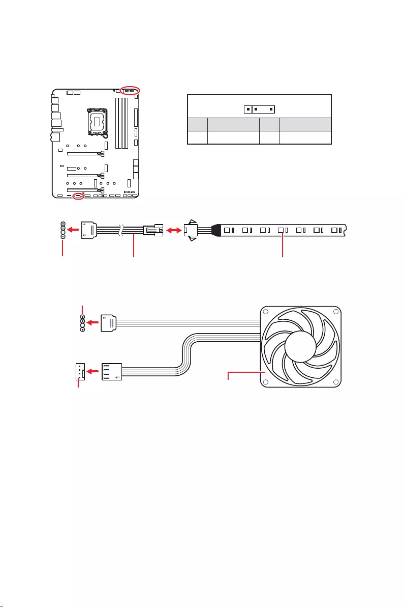
32
1
1
1
D
+5V
JRAINBOW
1
1 +5V 2 Data
3 No Pin 4 Ground
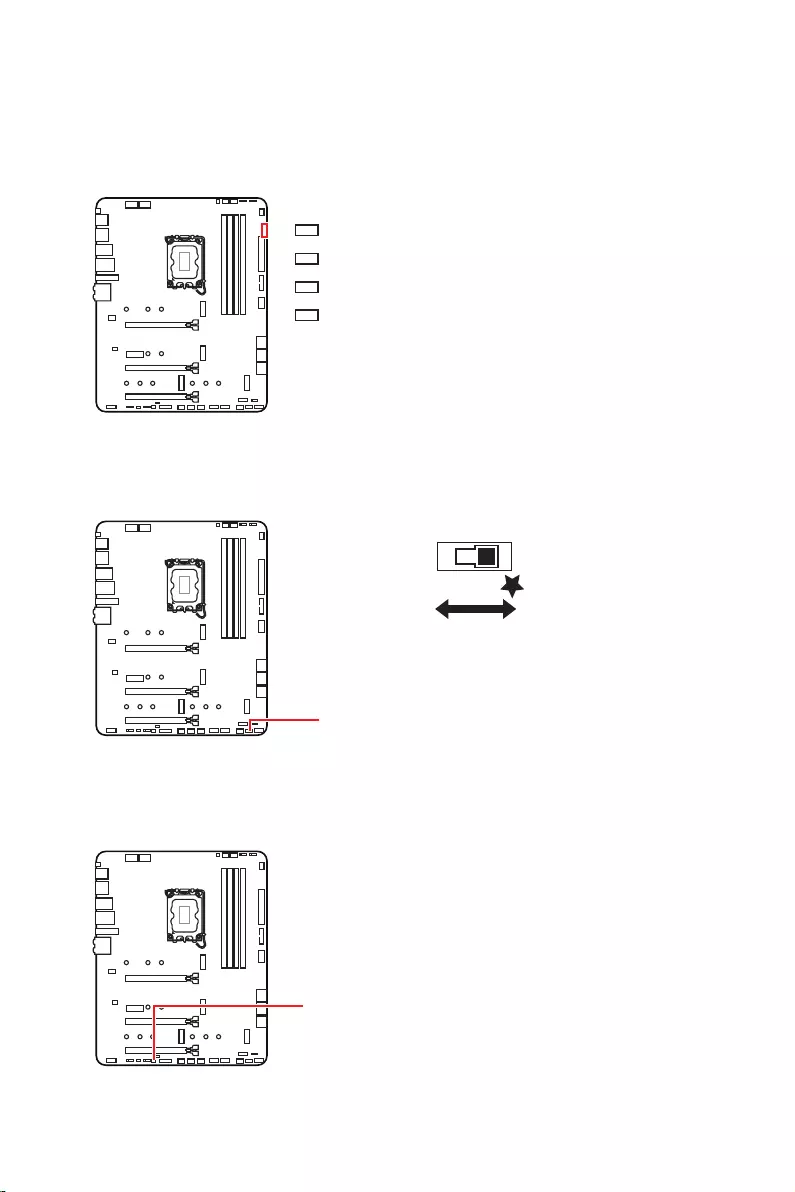
33
LED_SW1
LED_OFF LED_ON

34
1.
2.
3. Restart
4. F11
5.
6. Press any
7.
1.
2.
3.
Run DVDSetup.exe
DVDSetup.exe
4.
.
5. Install
6.
7.
8.
http://download.msi.com/manual/mb/MSICENTER.pdf

35
1.
2. Delete
3.

36
.
Delete
F1
F2
F3
F4
F5
F6
F7
F8
F9
F10
F12
http://download.msi.com/manual/mb/Intel600BIOSru.pdf

37
F6
.
1.
2.
3.
Yes
Del
Yes
4.
5. Yes
BIOS.
6.

38
1. Support.
2. .
3. Install.
4. Install.
5.
6.
1.
2.
3.
4.
5.
6.

1
………………………………………………………………………………. 3
…………………………………………………………………….. 4
……………………………………………………………………………….. 4
………………………………………………………………………………………………………… 5
……………………………………………………………………………………. 12
…………………………………………………………………………………………. 13
………………………………………………………………………………. 13
…………………………………………………………………………….. 13
…………………………………………………………………….. 14
……………………………………………………………………………… 17
…………………………………………………………………………………………….. 18
………………………………………………………………………………………….. 19
……………………………………………………………………… 20
………………………………………………….. 20
…………………………………………………………………….. 21
…………………………………………….. 23
…………………………………………………………. 23
………………………………………………………… 24
………………………………………………… 25
……………………………………………………. 26
………………………………………………………………. 26
……………………………………………………………………. 27
……………………………………………………………… 27
…………………………… 28
…………………………………………………………… 29
……………………………………………….. 30
…………………………………………. 30
……………………………………………………………………… 31
………………………………………………… 32
……………………………………………………………………………………….. 33
EZ Debug LED …………………………………………………………………………………………. 33
…………………………………………………………………. 33
………………………………………………………………………… 33
…………………………………………. 34
…………………………………………………….. 34

2
…………………………………………………………………………… 34
MSI Center ……………………………………………………………………………………………… 34
………………………………………………………………………………………………. 35
…………………………………………………………………………………………….. 36
……………………………………………………………………… 36
………………………………………………………………………………. 36
………………………………………………………………………………………… 37
……………………………………………………………………………. 37

3

4

5
Intel®

6
Realtek® ALC4080

7
x1
DisplayPort x1

8
EZ Debug LED x4
12 in. x 9.6 in. (30.5 cm x 24.4 cm)

9
UEFI AMI BIOS
ACPI 6.4, SMBIOS 3.4
MSI Center
Intel® Extreme Tuning Utility
MSI APP Player (BlueStacks)
Open Broadcaster Software (OBS)
Google Chrome™, Google Toolbar, Google Drive
Norton™ Internet Security Solution
Gaming Mode
Smart Priority
Gaming Highlight
LAN Manager
Mystic Light
Ambient Devices
Frozr AI Cooling
User Scenario
True Color
Live Update
Hardware Monitoring
Super Charger
Speed Up
Smart Image Finder
MSI Companion

10
Audio Boost 5
2.5G LAN
LAN Manager
Intel® WiFi
M.2 Shield Frozr
LED
Mystic Light
Mystic Light SYNC

11
Lightning Gen 4 M.2
Memory Boost
Core Boost
Game Boost
Lightning USB 20G
USB 3.2 Gen 2 10G
MSI Center
Click BIOS 5
EZ DEBUG LED
App player
Tile

12
MPG Z690 EDGE WIFI
1
1
1
1
1
1
1
2
1
1
1
1
1
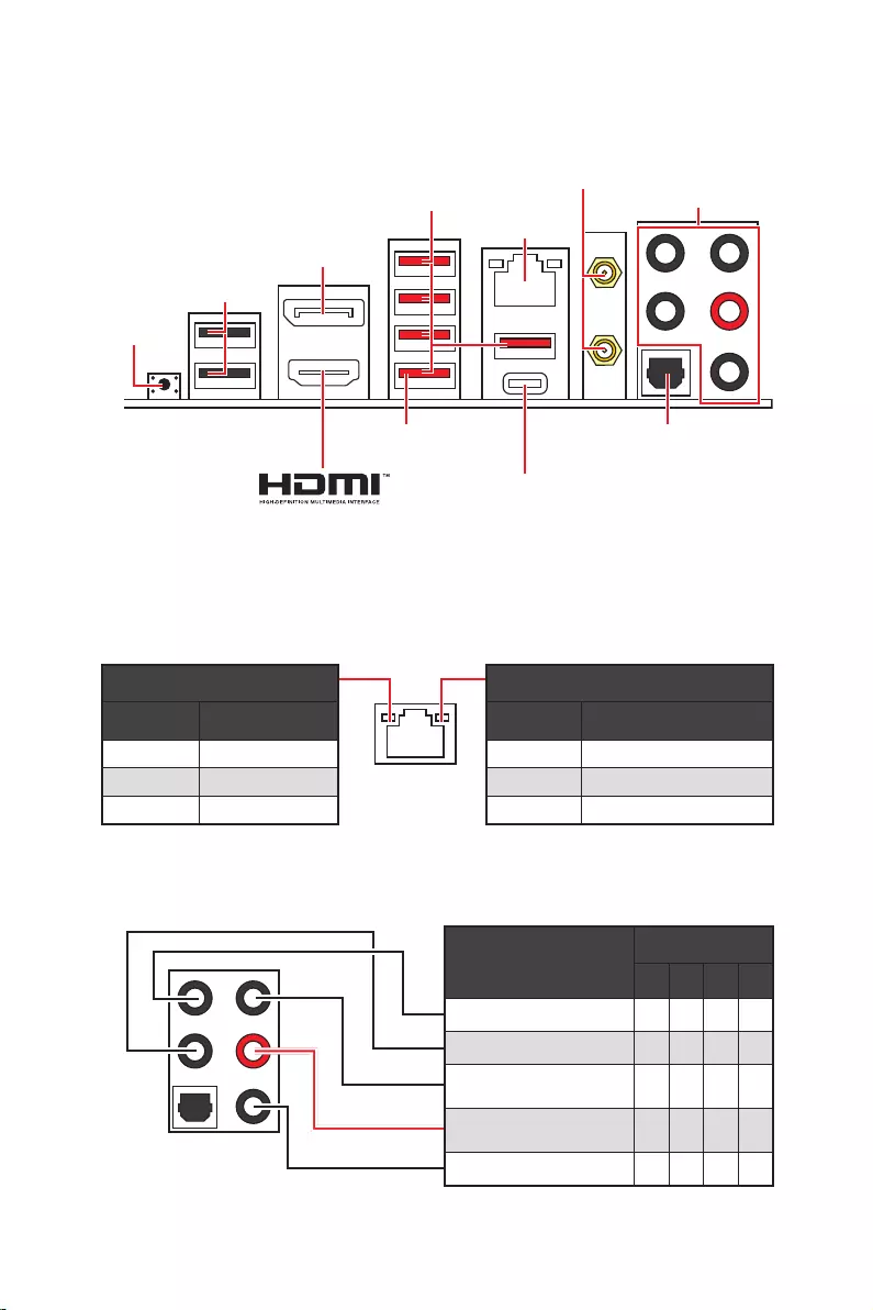
13
2468
Off
Off 10 Mbps
100/1000 Mbps
2.5 Gbps
2.5 Gbps LAN
DisplayPort
USB 3.2 Gen 2
Flash
USB 2.0
USB 3.2 Gen 2×2

14

15
AUDIO INPUT
AUDIO INPUT
Rear Front
Side Center/
Subwoofer

16
1.
2.
1
2

17
JUSB2
SYS_FAN5
SYS_FAN4
SYS_FAN3
SYS_FAN2
JBAT1
JTBT1
JTPM1
JRGB1
56
M2_3
JCI1
M2_1
SYS_FAN1
JDASH1
JUSB4
JUSB3
JUSB1
CPU_FAN1
SYS_FAN6
PUMP_FAN1
PCI_E1
PCI_E2
PCI_E3
PCI_E4
CPU_PWR1 JRAINBOW3JSMB1
CPU_PWR2 JRAINBOW2
JAUD1
JFP2
JRAINBOW1
JPWRLED1
LED_SW1
JFP1
ATX_PWR1
DIMMB1
DIMMB2
DIMMA1
M2_2
M2_4
DIMMA2

18
52.55 mm

19
DIMMA1 DIMMB1
DIMMA2 DIMMB2
DIMMA2 DIMMA2
DIMMB2
DIMMA1
DIMMA2
DIMMB1
DIMMB2
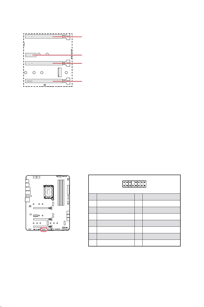
20
: PCIe 3.0 x4 (
1
2 16
15
1 TBT_Force_PWR 2 TBT_S0IX_Entry_REQ
3 TBT_CIO_Plug_Event# 4 TBT_S0IX_Entry_ACK
5 SLP_S3#_TBT 6 TBT_PSON_Override_N
7 SLP_S5#_TBT 8 No pin
9 Ground 10 SMBCLK_VSB
11 DG_PEWake 12 SMBDATA_VSB
13 TBT_RTD3_PWR_EN 14 Ground
15 TBT_Card_DET_R# 16 PD_IRQ#

21
M2_1
M2_2
M2_4
M2_3
1.
2.
2
2
2
2
1
1
1
1
11
1
M2_2
M2_3
M2_1
M2_4

22
30º30º
5
6
6
6
66 6
6
4
3
3.
4.
5.
6.
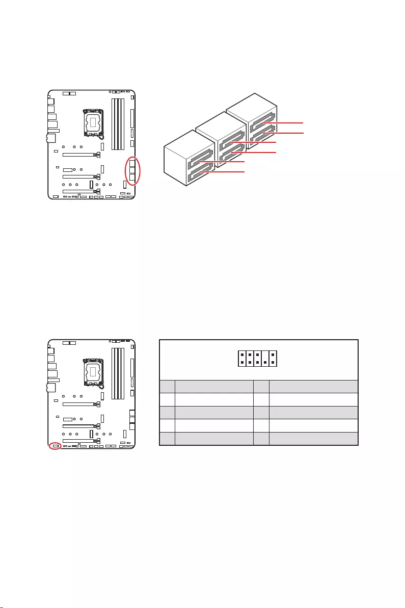
23
SATAA
SATA7
SATA5
SATAB
SATA8
SATA6
1
2 10
9
1 MIC L 2 Ground
3 MIC R 4 NC
5 Head Phone R 6 MIC Detection
7 SENSE_SEND 8 No Pin
9 Head Phone L 10 Head Phone Detection

24
1
2 10
9
+
+
+
+
Power LED
HDD LED Reset Switch
Reserved
Power Switch
JFP1
1 HDD LED + 2 Power LED +
3 4
5 Reset Switch 6 Power Switch
7 Reset Switch 8 Power Switch
9 Reserved 10 No Pin
1
JFP2
+
+
Speaker
Buzzer
1 2 Buzzer +
3 4 Speaker +

25
24
131
12
ATX_PWR1
1 +3.3V 13 +3.3V
2 +3.3V 14
3 Ground 15 Ground
4 +5V 16
5 Ground 17 Ground
6 +5V 18 Ground
7 Ground 19 Ground
8 PWR OK 20 Res
9 5VSB 21 +5V
10 +12V 22 +5V
11 +12V 23 +5V
12 +3.3V 24 Ground
5
4 1
8CPU_PWR1~2
1 Ground 5 +12V
2 Ground 6 +12V
3 Ground 7 +12V
4 Ground 8 +12V

26
1
10 11
20
1 Power 11 USB2.0+
2 USB3_RX_DN 12
3 USB3_RX_DP 13 Ground
4 Ground 14 USB3_TX_C_DP
5 USB3_TX_C_DN 15 USB3_TX_C_DN
6 USB3_TX_C_DP 16 Ground
7 Ground 17 USB3_RX_DP
8 18 USB3_RX_DN
9 USB2.0+ 19 Power
10 Ground 20 No Pin
JUSB4

27
1
2 10
9
1 VCC 2 VCC
3 4
5 USB0+ 6 USB1+
7 Ground 8 Ground
9 No Pin 10 NC
1
2 12
11
1 SPI Power 2 SPI Chip Select
3
Master In Slave Out (SPI Data)
4
Master Out Slave In (SPI Data)
5 Reserved 6 SPI Clock
7 Ground 8 SPI Reset
9 Reserved 10 No Pin
11 Reserved 12 Interrupt Request
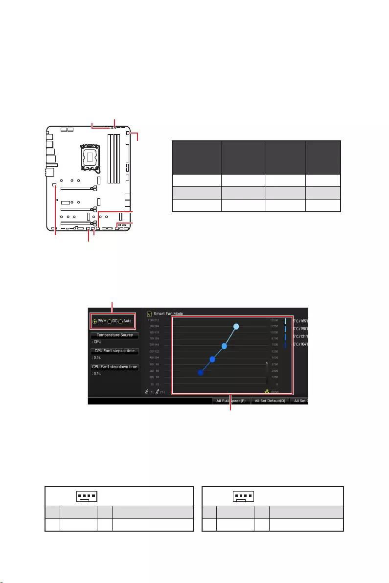
28
CPU_FAN1 2A 24W
PUMP_FAN1 3A 36W
SYS_FAN1~6 1A 12W
1
1 Ground 2 +12V
3 Sense 4 Speed Control Signal
1
1 Ground 2 Voltage Control
3 Sense 4 NC
SYS_FAN1
SYS_FAN3
SYS_FAN5
SYS_FAN4
PUMP_FAN1
CPU_FAN1
SYS_FAN2
SYS_FAN6
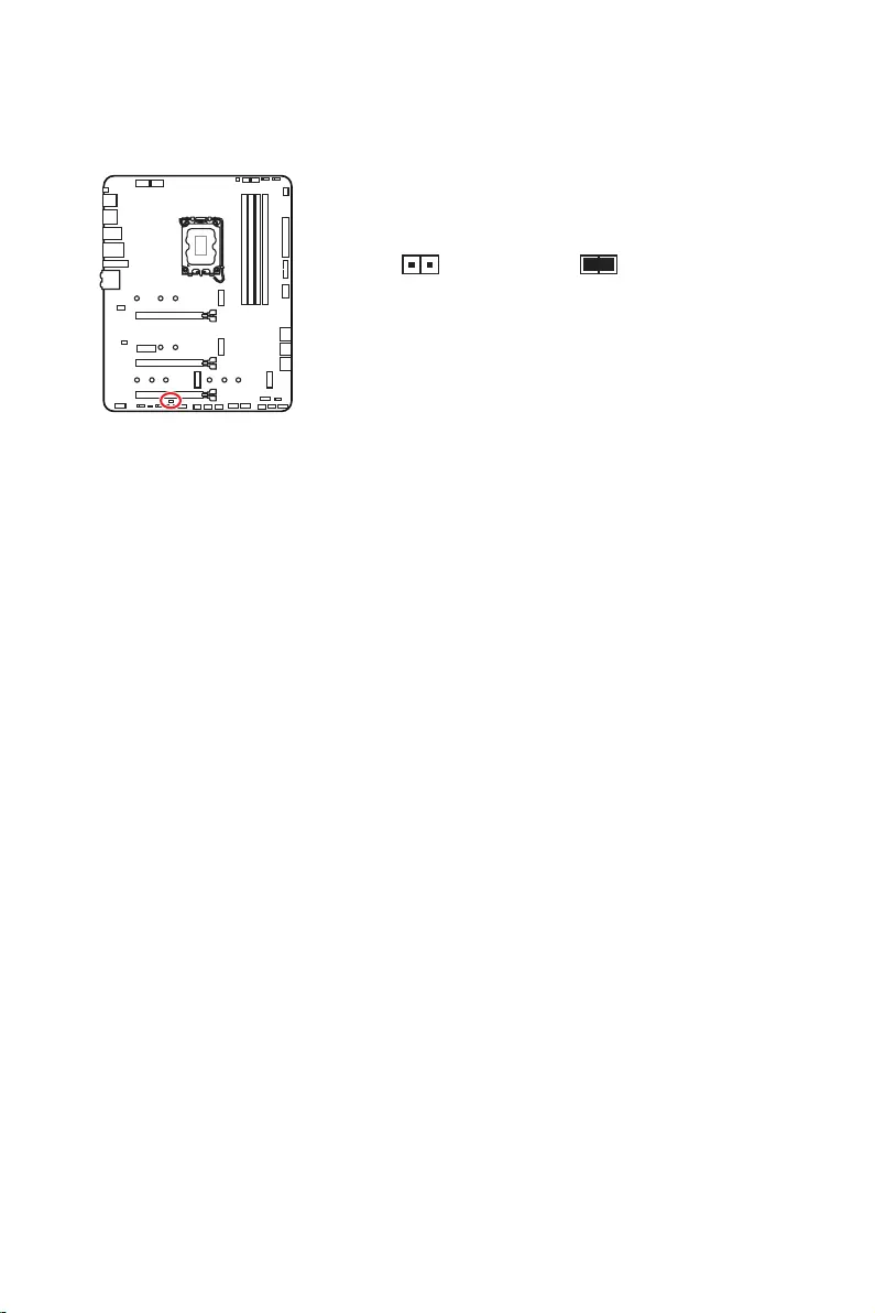
29
1.
2.
3.
4. Enabled
5. F10Enter
Yes
6.
1.
2. Reset
3. F10Enter
Yes
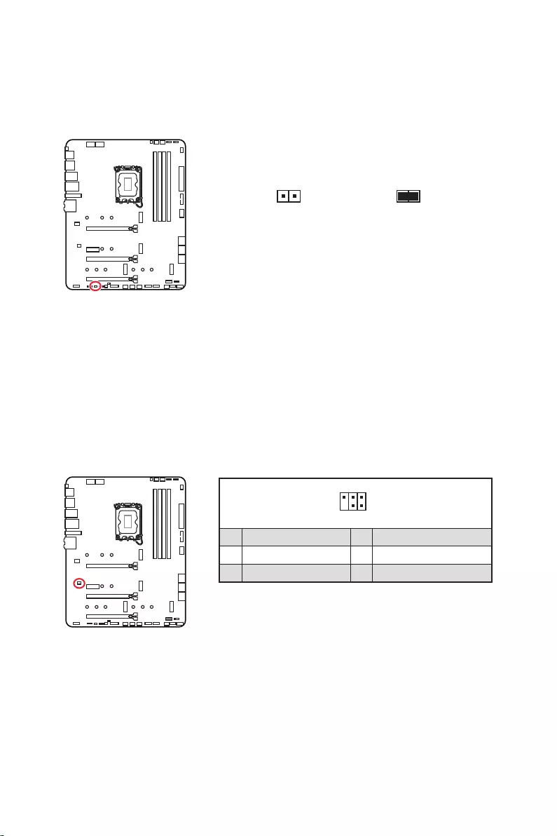
30
1.
2.
3.
4.
1
2 6
5
1 No Pin 2 NC
3 MCU_SMB_SCL_M 4 MCU_SMB_SDA_M
5 VCC5 6 Ground

31
1
GRB
1
1 +12V 2 G
3 R 4 B
1
1
GRB

32
1
1
1
D
+5V
1
1 +5V 2 Data
3 No Pin 4 Ground
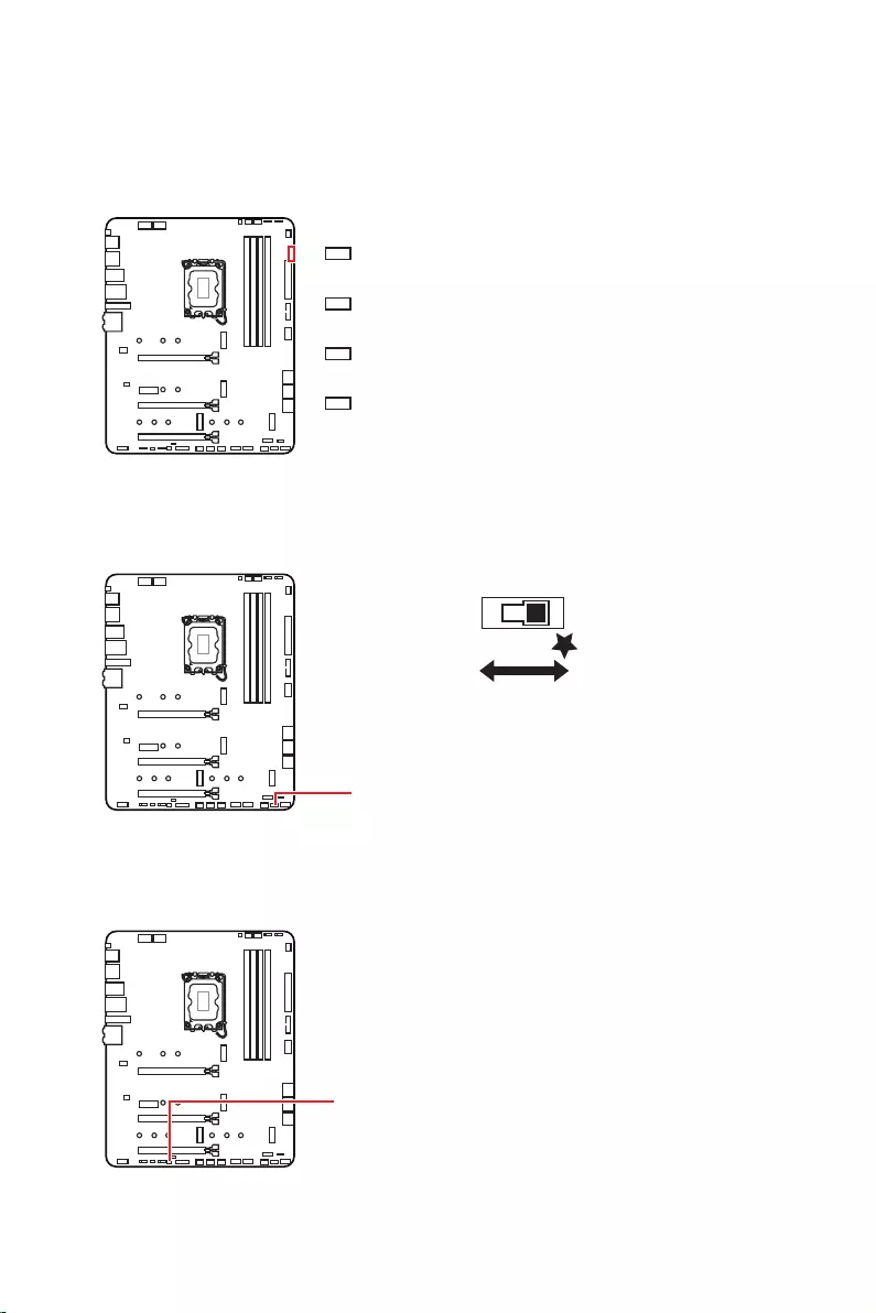
33
LED_SW1
LED_OFF LED_ON

34
1.
2.
3. Restart
4. F11
5.
6.
7.
1.
2.
3.
Run DVDSetup.exe
DVDSetup.exe
4.
5. Install
6.
7.
8.
http://download.msi.com/manual/mb/MSICENTER.pdf

35
1.
2.
Delete
3.

36
Delete
F1
F2
F3
F4
F5
F6
F7
F8
F9
F10
F12
http://download.msi.com/manual/mb/Intel600BIOSjp.pdf
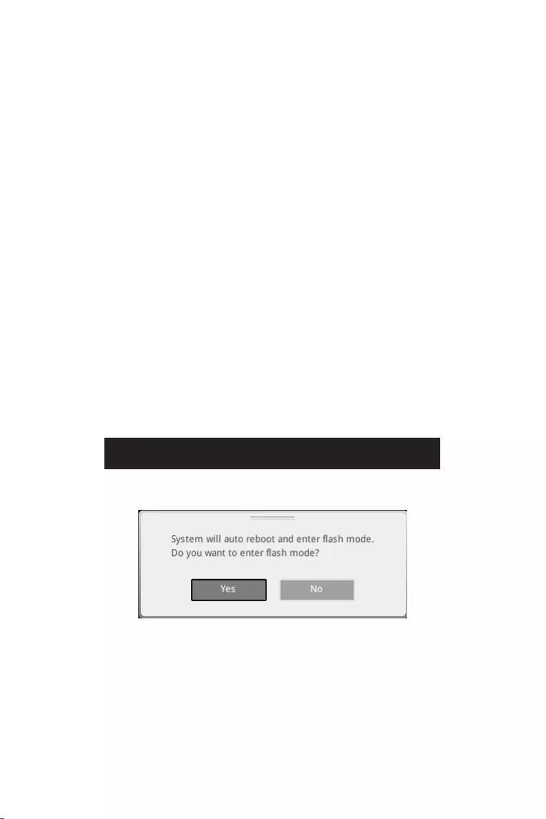
37
F6
1.
2.
3.
Yes
Delete
Yes
4.
5. Yes
6.

38
1. Support
2.
3. Install
4.
5.
6.
1.
2.
3.
4.
5.
6.

1
………………………………………………………………………………………………….. 3
……………………………………………………………………………….. 4
……………………………………………………………………………………………. 4
……………………………………………………………………………………………… 12
…………………………………………………………………………………………… 13
……………………………………………………………………………. 13
………………………………………………………………………………… 13
………………………………………………………………………………….. 14
……………………………………………………………………………………………… 17
………………………………………………………………………………………………… 18
………………………………………………………………………………………………. 19
…………………………………………………………………………. 20
……………………………………………………………….. 20
…………………………………………………………………………. 21
………………………………………………….. 23
………………………………………………………………………… 23
…………………………………………………………………….. 24
……………………………………………………… 25
………………………………………………………… 26
……………………………………………………………………. 26
…………………………………………………………………………. 27
…………………………………………………………………………… 27
……………………………………… 28
………………………………………………………………………………. 29
……………………………………………………… 30
…………………………………………………………………… 30
…………………………………………………………………………… 31
……………………………………….. 32
……………………………………………………………………………………………. 33
…………………………………………………………………………………………. 33
…………………………………………………………………………. 33
……………………………………………………………………….. 33
………………………………………………………………. 34
…………………………………………………………….. 34
…………………………………………………………………………………….. 34
…………………………………………………………………………………………………. 34

2
………………………………………………………………………………………………. 35
…………………………………………………………………………………. 36
………………………………………………………………………………………………… 36
………………………………………………………………………………………………… 37
……………………………………………………………………………. 37

3

4

5
® Z690
4x DDR5
® XMP 3.0 OC
3x PCIe x16
PCI_E1 (CPU)
PCIe 5.0 x16
PCI_E3 & PCI_E4 ( Z690 )
PCIe 3.0 x4
1x PCIe 3.0 x1 ( Z690 )
AMD® CrossFire™
1x HDR HDMI 2.1, */**
1.4 ,
*/**

6
6x SATA 6Gb/s
SATA5~8 (Z690 )
SATAA~B (ASMedia ASM1061)
4x M.2 (Key M)
M2_1 (CPU)
PCIe 4.0 x4
2260/ 2280/ 22110
M2_2 (Z690 )
PCIe 4.0 x4
2260/ 2280
M2_3 (Z690 )
PCIe 4.0 x4
SATA 6Gb/s
2242/ 2260/ 2280
M2_4 (Z690 )
PCIe 4.0 x4
SATA 6Gb/s
2242/ 2260/ 2280
M2_2~4 ® Optane™ Memory
*
RAID 0, RAID 1 RAID 5 (M.2 PCIe
Realtek® ALC4080

7
6x USB 3.2 Gen 2 10Gbps
)
2x USB 3.2 Gen 1 5Gbps USB
4x USB 2.0 USB
1x
2.4Gbps
802.11 a/ b/ g/ n/ ac/ ax
® 5.2**, FIPS, FISMA
.
2x USB 2.0
1x
1x HDMI
1x 2.5Gbps LAN (RJ45)
5x

8
6x SATA 6Gb/s
4x M.2
1x USB 3.2 Gen 1 5Gbps ( 2 USB 3.2 Gen 1 5Gbps
)
2x USB 2.0 ( 4 USB 2.0 )
1x EZ LED
4x EZ LED
NUVOTON NCT6687D
ATX
12 in. x 9.6 in. (30.5 cm x 24.4 cm)

9
1x 256 Mb flash
UEFI AMI BIOS
ACPI 6.4, SMBIOS 3.4
®
MSI APP Player (BlueStacks)
Open Broadcaster Software (OBS)
True Color

10
2.5G LAN
LED

11
USB 3.2 Gen 2 10G
USB Type A+C
2oz Copper thickened PCB
MSI
App player

12
MPG Z690 EDGE WIFI
1
1
SATA 6G (2 1
1
1
1
1
2
1
1
1
1
1
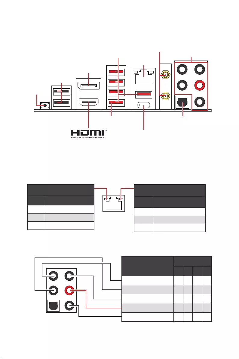
13
2468
2.5 Gbps LAN
USB 3.2 Gen 2
USB 2.0
USB 3.2 Gen 2×2

14

15
AUDIO INPUT
AUDIO INPUT
Rear Front
Side Center/
Subwoofer

16
1.
2.
1
2
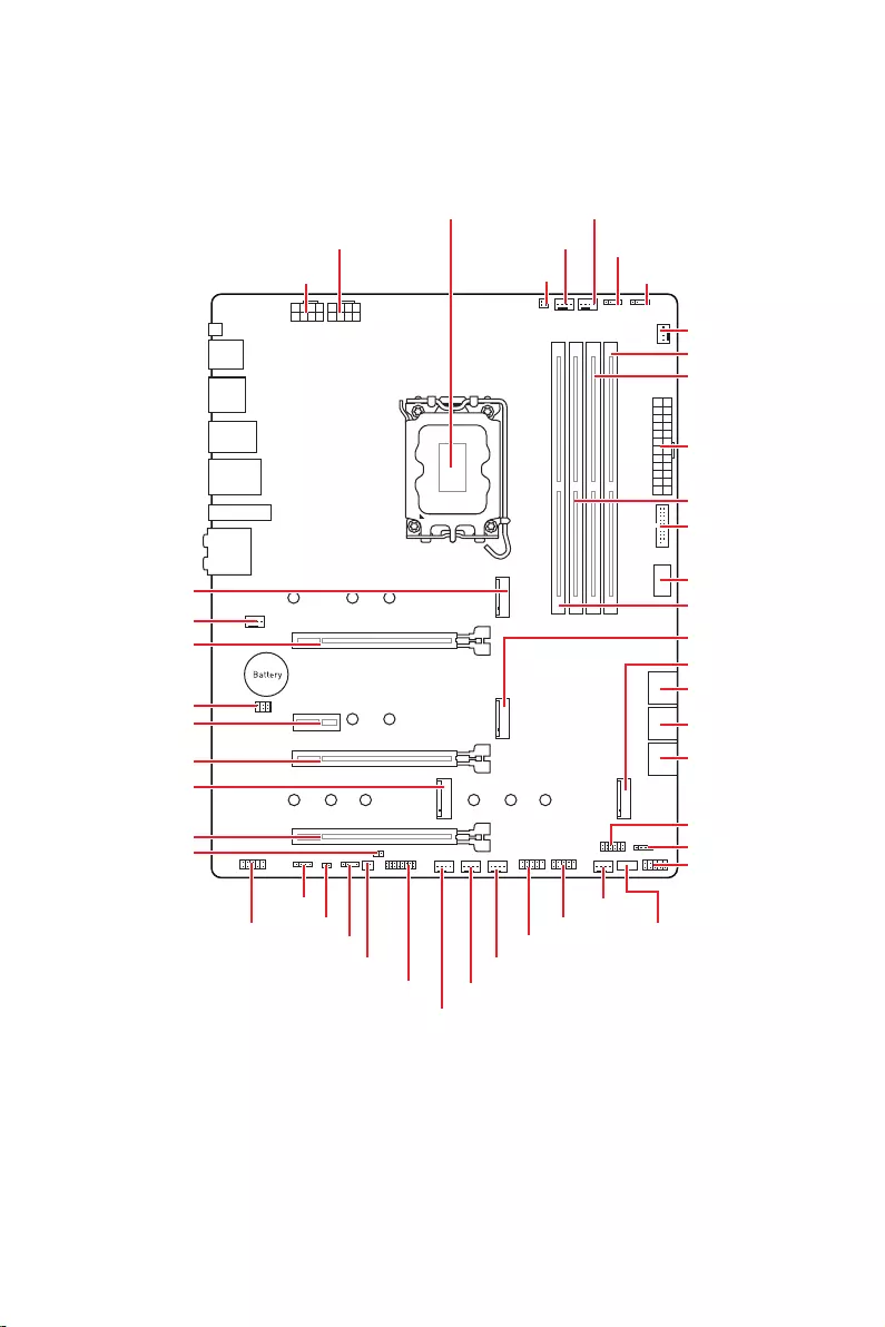
17
JUSB2
SYS_FAN5
SYS_FAN4
SYS_FAN3
SYS_FAN2
JBAT1
JTBT1
JTPM1
JRGB1
56
M2_3
JCI1
M2_1
SYS_FAN1
JDASH1
JUSB4
JUSB3
JUSB1
CPU_FAN1
SYS_FAN6
PUMP_FAN1
PCI_E1
PCI_E2
PCI_E3
PCI_E4
CPU_PWR1 JRAINBOW3JSMB1
CPU_PWR2 JRAINBOW2
JAUD1
JFP2
JRAINBOW1
JPWRLED1
LED_SW1
JFP1
ATX_PWR1
DIMMB1
DIMMB2
DIMMA1
M2_2
M2_4
DIMMA2

18
52.55 mm

19
DIMMA1 DIMMB1
DIMMA2 DIMMB2
DIMMA2 DIMMA2
DIMMB2
DIMMA1
DIMMA2
DIMMB1
DIMMB2

20
: PCIe 5.0 x16 (CPU)
: PCIe 3.0 x4 (
1
2 16
15
1 TBT_Force_PWR 2 TBT_S0IX_Entry_REQ
3 TBT_CIO_Plug_Event# 4 TBT_S0IX_Entry_ACK
5 SLP_S3#_TBT 6 TBT_PSON_Override_N
7 SLP_S5#_TBT 8 No pin
9 Ground 10 SMBCLK_VSB
11 DG_PEWake 12 SMBDATA_VSB
13 TBT_RTD3_PWR_EN 14 Ground
15 TBT_Card_DET_R# 16 PD_IRQ#
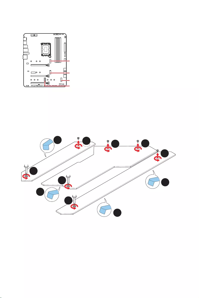
21
M2_1
M2_2
M2_4
M2_3
®
1.
2.
2
2
2
2
1
1
1
1
11
1
M2_2
M2_3
M2_1
M2_4
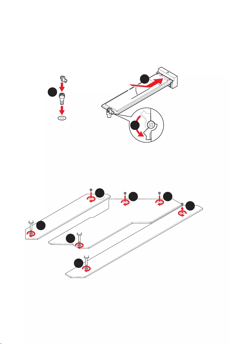
22
30º30º
5
6
6
6
66 6
6
4
3
3.
4.
5.
6.

23
SATAA
SATA7
SATA5
SATAB
SATA8
SATA6
1
2 10
9
1 MIC L 2 Ground
3 MIC R 4 NC
5 Head Phone R 6 MIC Detection
7 SENSE_SEND 8 No Pin
9 Head Phone L 10 Head Phone Detection

24
1
2 10
9
+
+
+
+
HDD LED
Reserved
JFP1
1 HDD LED + 2 Power LED +
3 4
5 Reset Switch 6 Power Switch
7 Reset Switch 8 Power Switch
9 Reserved 10 No Pin
1
JFP2
+
+
Speaker
Buzzer
1 2 Buzzer +
3 4 Speaker +

25
24
131
12
ATX_PWR1
1 +3.3V 13 +3.3V
2 +3.3V 14
3 Ground 15 Ground
4 +5V 16
5 Ground 17 Ground
6 +5V 18 Ground
7 Ground 19 Ground
8 PWR OK 20 Res
9 5VSB 21 +5V
10 +12V 22 +5V
11 +12V 23 +5V
12 +3.3V 24 Ground
5
4 1
8CPU_PWR1~2
1 Ground 5 +12V
2 Ground 6 +12V
3 Ground 7 +12V
4 Ground 8 +12V
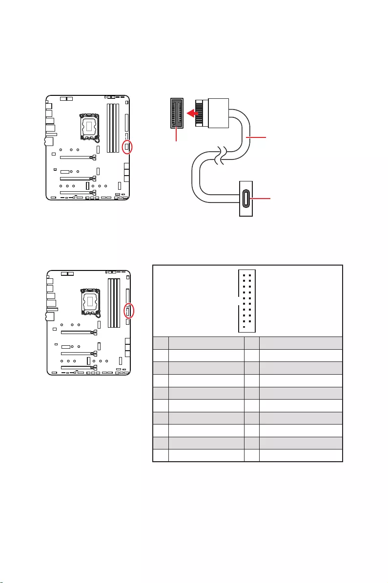
26
1
10 11
20
1 Power 11 USB2.0+
2 USB3_RX_DN 12
3 USB3_RX_DP 13 Ground
4 Ground 14 USB3_TX_C_DP
5 USB3_TX_C_DN 15 USB3_TX_C_DN
6 USB3_TX_C_DP 16 Ground
7 Ground 17 USB3_RX_DP
8 18 USB3_RX_DN
9 USB2.0+ 19 Power
10 Ground 20 No Pin
JUSB4

27
1
2 10
9
1 VCC 2 VCC
3 4
5 USB0+ 6 USB1+
7 Ground 8 Ground
9 No Pin 10 NC
®
1
2 12
11
1 SPI Power 2 SPI Chip Select
3
Master In Slave Out (SPI Data)
4
Master Out Slave In (SPI Data)
5 Reserved 6 SPI Clock
7 Ground 8 SPI Reset
9 Reserved 10 No Pin
11 Reserved 12 Interrupt Request

28
PWM
CPU_FAN1 2A 24W
PUMP_FAN1 PWM 3A 36W
SYS_FAN1~6 DC 1A 12W
1
1 Ground 2 +12V
3 Sense 4 Speed Control Signal
1
1 Ground 2 Voltage Control
3 Sense 4 NC
SYS_FAN1
SYS_FAN3
SYS_FAN5
SYS_FAN4
PUMP_FAN1
CPU_FAN1
SYS_FAN2
SYS_FAN6
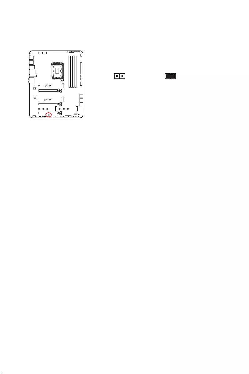
29
1.
2.
3.
4.
5. EnterYes
6.
1.
2.
3. F10Enter Yes

30
1.
2.
3.
4.
1
2 6
5
1 No Pin 2 NC
3 MCU_SMB_SCL_M 4 MCU_SMB_SDA_M
5 VCC5 6 Ground

31
1
GRB
JRGB
1
1 +12V 2 G
3 R 4 B
1
1
GRB

32
1
1
1
D
+5V
JRAINBOW
1
1 +5V 2 Data
3 No Pin 4 Ground

33
LED_SW1

34
1.
2.
3. Restart
4. F11
5.
6.
7.
1.
2.
3. Run
DVDSetup.exe
DVDSetup.exe
4.
5. Install
6.
7.
8.
http://download.msi.com/manual/mb/MSICENTER.pdf

35
1.
2.
Delete
3.

36
Delete
F1
F2
F3
F4
F5
F6
F7
F8
F9
F10
F12
http://download.msi.com/manual/mb/Intel600BIOSkr.pdf
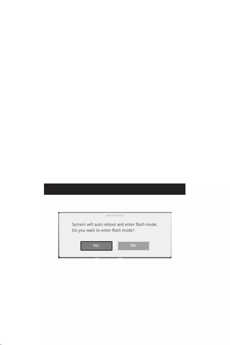
37
F6
1.
2.
3.
Yes
Del
Yes
4.
5. Yes
6.

38
1. Support
2.
3. Install
4.
5.
6.
1.
2.
3.
4.
5.
6.

1
………………………………………………………………………………………………….. 3
………………………………………………………………………………….. 4
……………………………………………………………………………………… 4
………………………………………………………………………………………………………… 5
………………………………………………………………………………………………… 12
…………………………………………………………………………………………………. 13
………………………………………………………………………… 13
………………………………………………………………………………………. 13
…………………………………………………………………………………. 14
………………………………………………………………………………………………… 17
………………………………………………………………………………………………… 18
……………………………………………………………………………………………… 19
…………………………………………………………………………. 20
……………………………………………………………….. 20
………………………………………………………………………….. 21
…………………………………………………….. 23
………………………………………………………………………………. 23
………………………………………………………………………… 24
………………………………………………………… 25
…………………………………………………………… 26
……………………………………………………………………… 26
……………………………………………………………………………. 27
……………………………………………………………………………… 27
……………………………….. 28
………………………………………………………………………………….. 29
…………………………………………………… 30
…………………………………………………………………………. 30
……………………………………………………………………………… 31
……………………………………………………….. 32
…………………………………………………………………………………….. 33
……………………………………………………………………………………… 33
………………………………………………………………….. 33
……………………………………………………………………….. 33
……………………………………………………… 34
………………………………………………………………….. 34

2
………………………………………………………………………………………….. 34
MSI Center ……………………………………………………………………………………………… 34
………………………………………………………………………………………………. 35
……………………………………………………………………………………………….. 36
………………………………………………………………………………………… 36
……………………………………………………………………………………… 36
……………………………………………………………………………………………….. 37
……………………………………………………………………………………………….. 37

3

4

5
® XMP 3.0 OC
60Hz */**
4K 60Hz*/**

6
)
)
)
10*
Realtek® ALC4080

7

8
ATX

9
UEFI AMI BIOS
MSI Center
Intel® Extreme Tuning Utility
MSI APP Player (BlueStacks)
Open Broadcaster Software (OBS)
Norton™ Internet Security Solution
Gaming Mode
Smart Priority
Gaming Highlight
Mystic Light
Ambient Devices
Frozr AI Cooling
User Scenario
True Color
Live Update
Super Charger
Speed Up
Smart Image Finder
MSI Companion

10
Audio Boost 5
Intel® WiFi
M.2 Shield Frozr
Mystic Light
Ambient Devices Support

11
Lightning Gen 4 M.2
Memory Boost
Lightning USB 20G
USB 3.2 Gen 2 10G
Server PCB
MSI Center
Frozr AI Cooling
App player
Tile

12
MPG Z690 EDGE WIFI
1
1
1
1
1
1
1
2
1
1
1
1
1
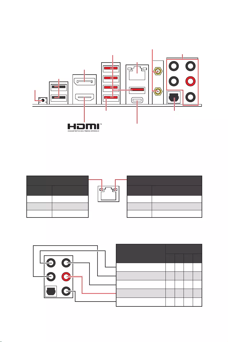
13
2468
2.5 Gbps
DisplayPort
USB 3.2 Gen 2
USB 2.0
USB 3.2 Gen 2×2
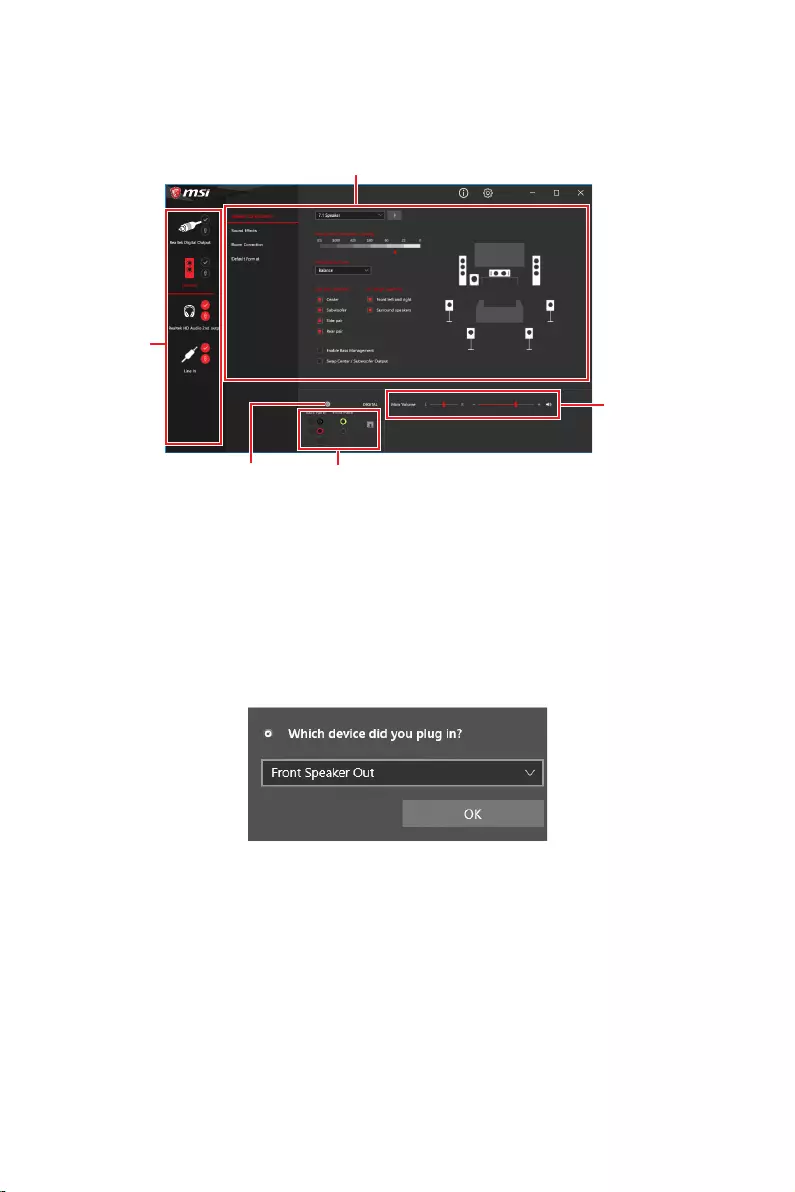
14

15
AUDIO INPUT
AUDIO INPUT
Rear Front
Side Center/
Subwoofer

16
1.
2.
1
2

17
JUSB2
SYS_FAN5
SYS_FAN4
SYS_FAN3
SYS_FAN2
JBAT1
JTBT1
JTPM1
JRGB1
56
M2_3
JCI1
M2_1
SYS_FAN1
JDASH1
JUSB4
JUSB3
JUSB1
CPU_FAN1
SYS_FAN6
PUMP_FAN1
PCI_E1
PCI_E2
PCI_E3
PCI_E4
CPU_PWR1 JRAINBOW3JSMB1
CPU_PWR2 JRAINBOW2
JAUD1
JFP2
JRAINBOW1
JPWRLED1
LED_SW1
JFP1
ATX_PWR1
DIMMB1
DIMMB2
DIMMA1
M2_2
M2_4
DIMMA2

18
52.55 mm
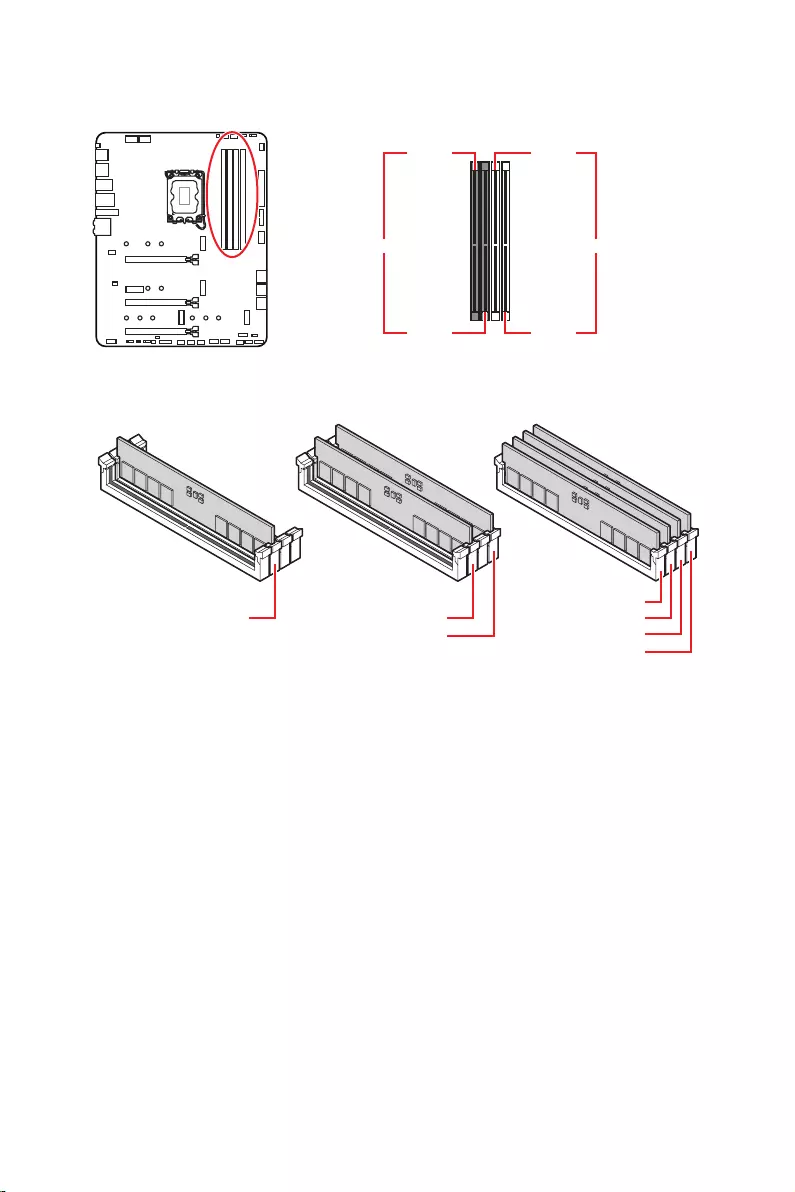
19
DIMMA1 DIMMB1
DIMMA2 DIMMB2
DIMMA2 DIMMA2
DIMMB2
DIMMA1
DIMMA2
DIMMB1
DIMMB2
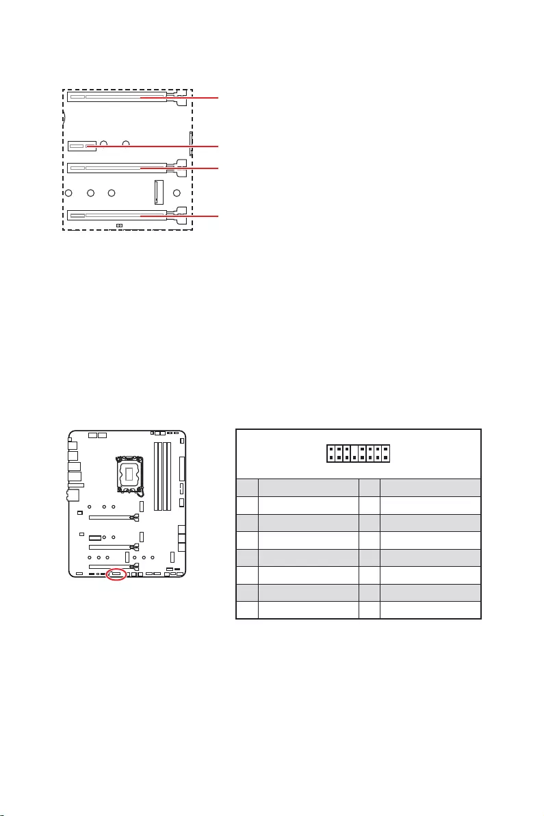
20
: PCI
MSI Gaming Series
1
2 16
15
1 TBT_Force_PWR 2 TBT_S0IX_Entry_REQ
3 TBT_CIO_Plug_Event# 4 TBT_S0IX_Entry_ACK
5 SLP_S3#_TBT 6 TBT_PSON_Override_N
7 SLP_S5#_TBT 8 No pin
9 Ground 10 SMBCLK_VSB
11 DG_PEWake 12 SMBDATA_VSB
13 TBT_RTD3_PWR_EN 14 Ground
15 TBT_Card_DET_R# 16 PD_IRQ#

21
M2_1
M2_2
M2_4
M2_3
1.
2.
2
2
2
2
1
1
1
1
11
1
M2_2
M2_3
M2_1
M2_4

22
30º30º
5
6
6
6
66 6
6
4
3
3.
4.
5.
6.
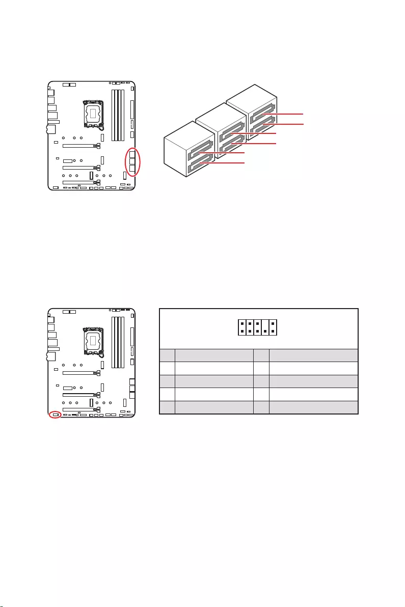
23
SATAA
SATA7
SATA5
SATAB
SATA8
SATA6
1
2 10
9
1 MIC L 2 Ground
3 MIC R 4 NC
5 Head Phone R 6 MIC Detection
7 SENSE_SEND 8 No Pin
9 Head Phone L 10 Head Phone Detection
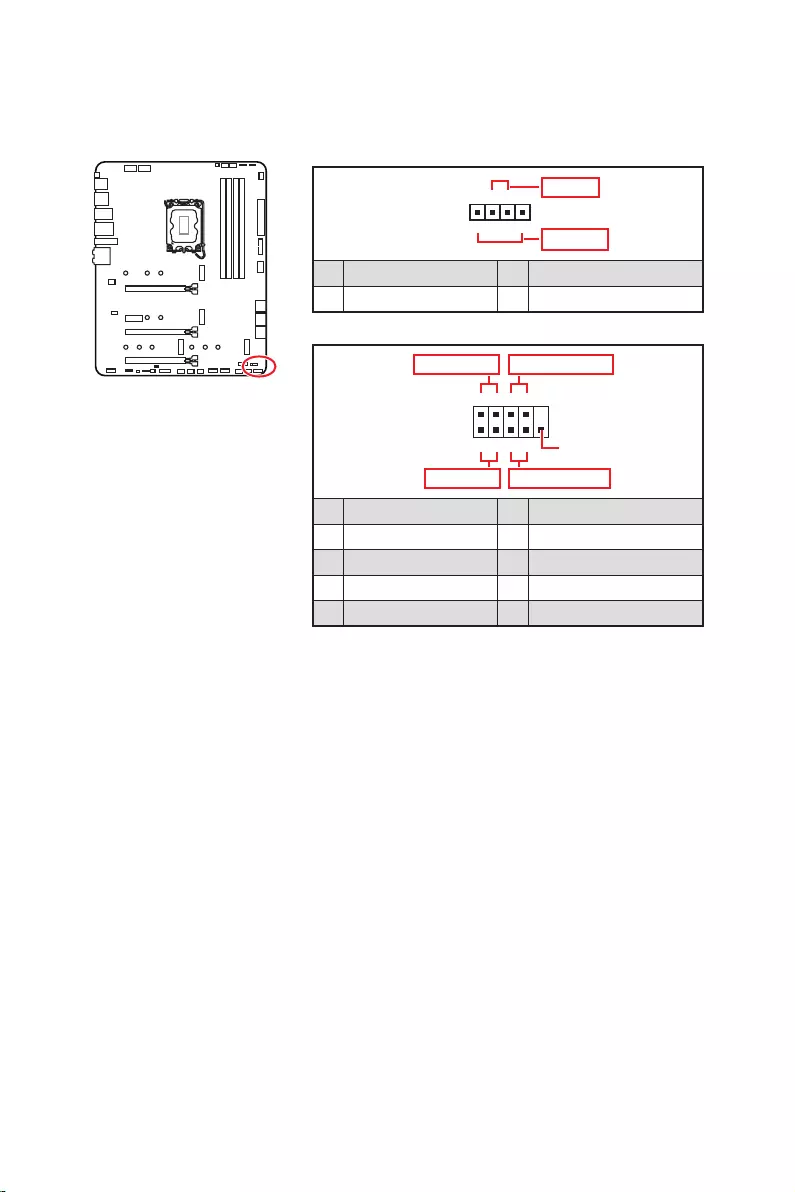
24
1
2 10
9
+
+
+
+
Power LED
HDD LED Reset Switch
Reserved
Power Switch
JFP1
1 HDD LED + 2 Power LED +
3 4
5 Reset Switch 6 Power Switch
7 Reset Switch 8 Power Switch
9 Reserved 10 No Pin
1
JFP2
+
+
Speaker
Buzzer
1 2 Buzzer +
3 4 Speaker +

25
24
131
12
ATX_PWR1
1 +3.3V 13 +3.3V
2 +3.3V 14
3 Ground 15 Ground
4 +5V 16
5 Ground 17 Ground
6 +5V 18 Ground
7 Ground 19 Ground
8 PWR OK 20 Res
9 5VSB 21 +5V
10 +12V 22 +5V
11 +12V 23 +5V
12 +3.3V 24 Ground
5
4 1
8CPU_PWR1~2
1 Ground 5 +12V
2 Ground 6 +12V
3 Ground 7 +12V
4 Ground 8 +12V

26
1
10 11
20
1 Power 11 USB2.0+
2 USB3_RX_DN 12
3 USB3_RX_DP 13 Ground
4 Ground 14 USB3_TX_C_DP
5 USB3_TX_C_DN 15 USB3_TX_C_DN
6 USB3_TX_C_DP 16 Ground
7 Ground 17 USB3_RX_DP
8 18 USB3_RX_DN
9 USB2.0+ 19 Power
10 Ground 20 No Pin
JUSB4
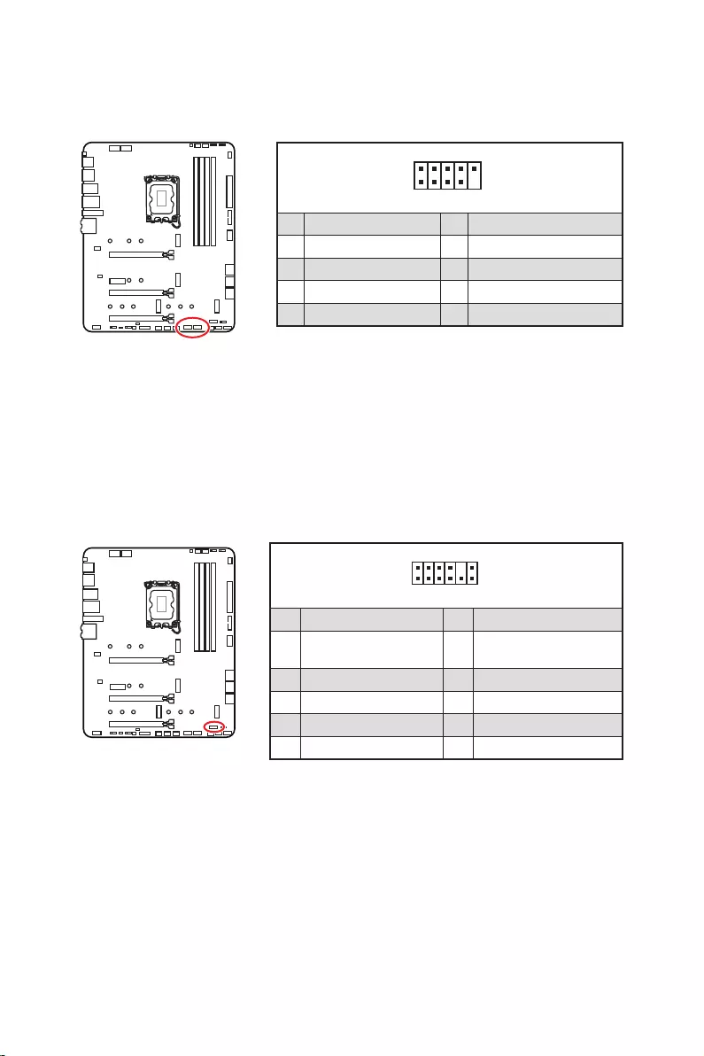
27
1
2 10
9
1 VCC 2 VCC
3 4
5 USB0+ 6 USB1+
7 Ground 8 Ground
9 No Pin 10 NC
1
2 12
11
1 SPI Power 2 SPI Chip Select
3
Master In Slave Out
(SPI Data)
4
Master Out Slave In
(SPI Data)
5 Reserved 6 SPI Clock
7 Ground 8 SPI Reset
9 Reserved 10 No Pin
11 Reserved 12 Interrupt Request
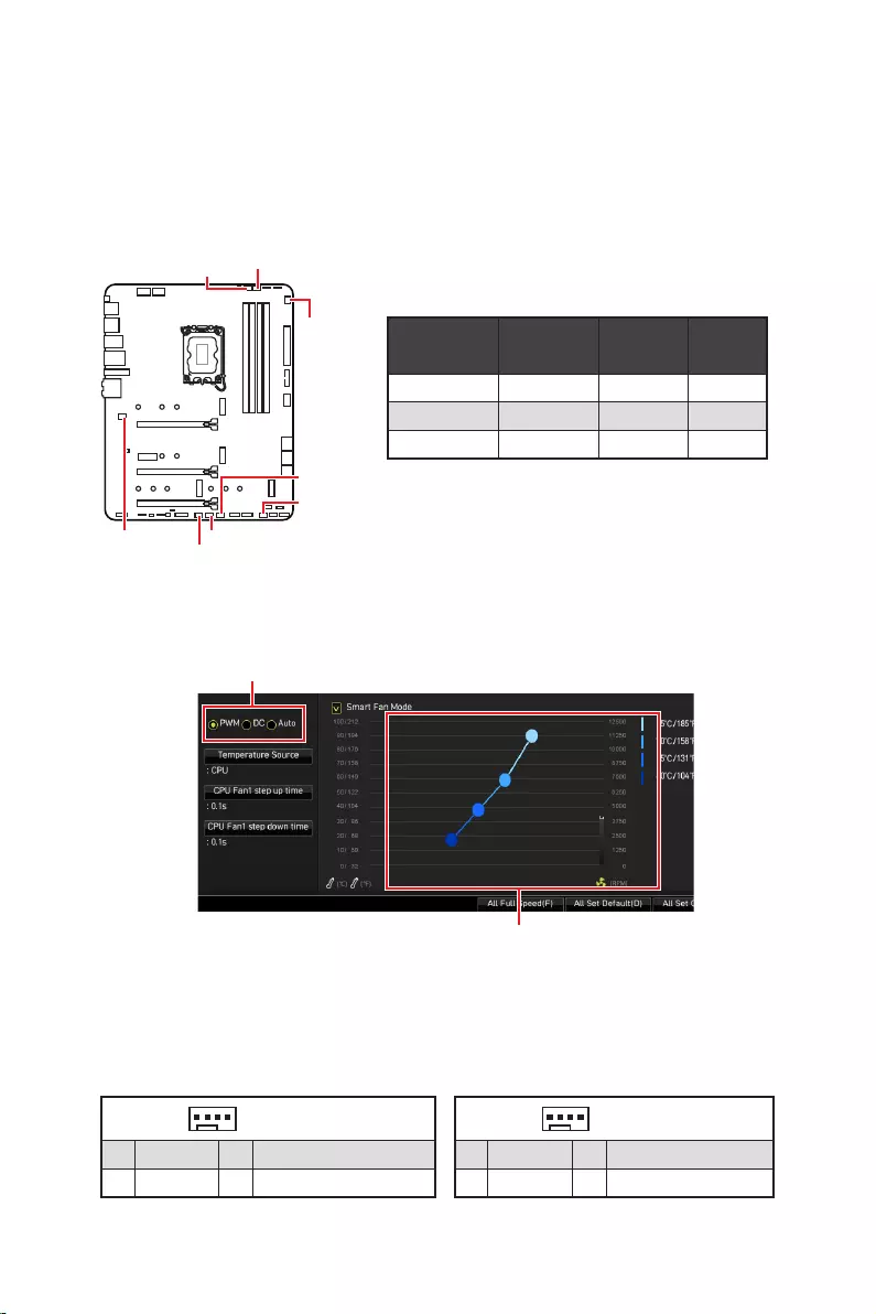
28
PWM
CPU_FAN1 2A 24W
PUMP_FAN1 3A 36W
SYS_FAN1~6 1A 12W
1
1 Ground 2 +12V
3 Sense 4 Speed Control Signal
1
1 Ground 2 Voltage Control
3 Sense 4 NC
SYS_FAN1
SYS_FAN3
SYS_FAN5
SYS_FAN4
PUMP_FAN1
CPU_FAN1
SYS_FAN2
SYS_FAN6

29
1.
2.
3.
4. Enabled
5. F10Enter
6.
1. .
2. Reset
3. F10 EnterYes

30
1.
2.
3.
4.
1
2 6
5
1 No Pin 2 NC
3 MCU_SMB_SCL_M 4 MCU_SMB_SDA_M
5 VCC5 6 Ground

31
1
GRB
1
1 +12V 2 G
3 R 4 B
1
1
GRB

32
1
1
1
D
+5V
JRAINBOW
1
1 +5V 2 Data
3 No Pin 4 Ground

33
LED_SW1
LED_OFF LED_ON

34
msi.com
1.
2.
3.
4. F11
5.
6.
7.
1.
2.
3. DVDSetup.exe
DVDSetup.exe
4.
5.
6.
7.
8.
http://download.msi.com/manual/mb/MSICENTERCT.pdf

35
1.
2.
Delete
3.

36
Delete
F1
F2
F3
F4
F5
F6
F7
F8
F9
F10
F12
http://download.msi.com/manual/mb/Intel600BIOStc.pdf
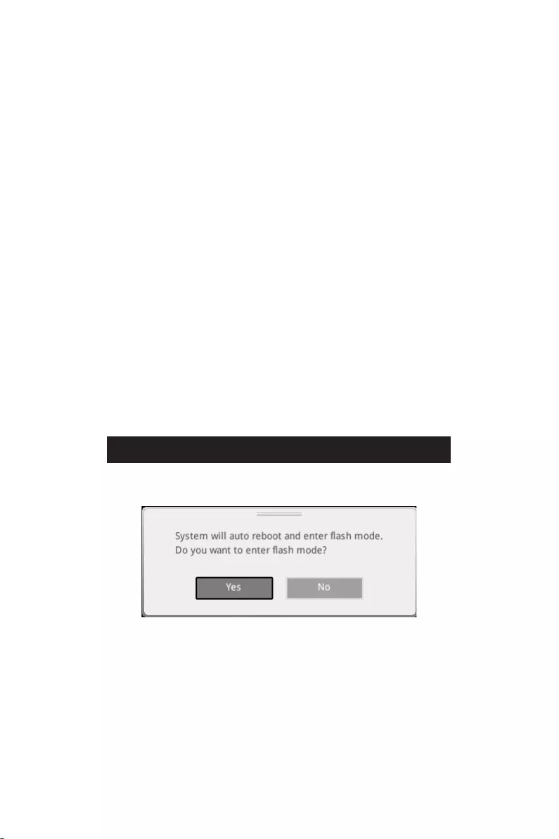
37
F6
1. ,
2.
3.
Del
4.
5. Yes
6.

38
1. Support
2.
3. Install
4.
5.
6.
1.
2.
3.
4.
5.
6.

1
………………………………………………………………………………………………….. 3
……………………………………………………………………………………… 4
……………………………………………………………………………………… 4
………………………………………………………………………………………………………… 5
………………………………………………………………………………………………… 12
………………………………………………………………………………………….. 13
………………………………………………………………………………. 13
………………………………………………………………………………………….. 13
…………………………………………………………………………………. 14
………………………………………………………………………………………………… 17
………………………………………………………………………………………………… 18
……………………………………………………………………………………………… 19
…………………………………………………………………………. 20
……………………………………………………………….. 20
………………………………………………………………………….. 21
…………………………………………………….. 23
………………………………………………………………………………. 23
………………………………………………………………………… 24
………………………………………………………… 25
…………………………………………………………… 26
………………………………………………………………………. 26
……………………………………………………………………………. 27
……………………………………………………………………………… 27
……………………………………… 28
……………………………………………………………………………. 29
………………………………………………………….. 30
………………………………………………………………………… 30
……………………………………………………………………………… 31
………………………………………………………….. 32
……………………………………………………………………………………………. 33
……………………………………………………………………………………… 33
……………………………………………………………………… 33
……………………………………………………………………….. 33
……………………………………………………… 34
………………………………………………………………….. 34

2
…………………………………………………………………………………………………. 34
MSI Center ……………………………………………………………………………………………… 34
………………………………………………………………………………………………. 35
……………………………………………………………………………………………….. 36
………………………………………………………………………………………… 36
…………………………………………………………………………………………. 36
……………………………………………………………………………………………….. 37
……………………………………………………………………………………………….. 37

3
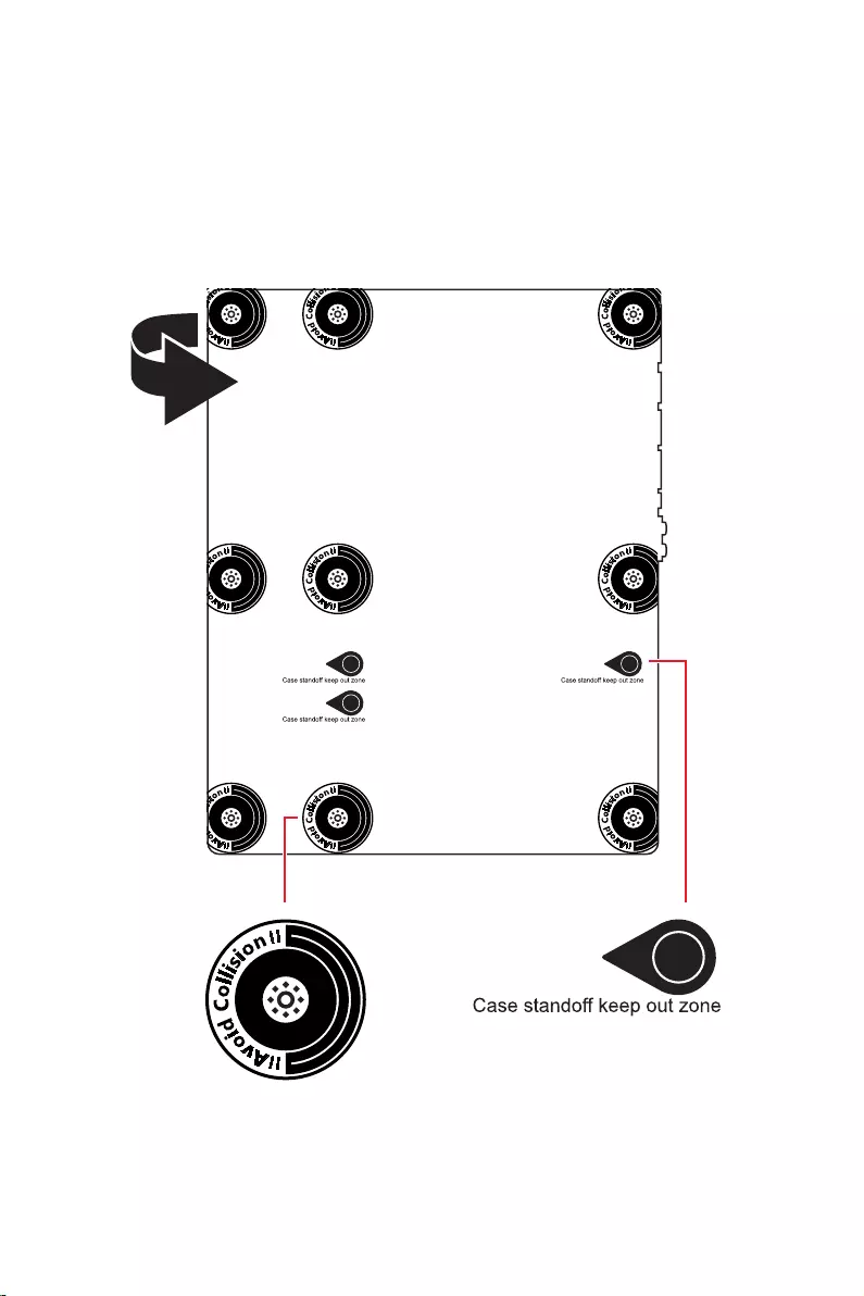
4

5
® XMP 3.0 OC
*/**
4K 60Hz*/**

6
)
)
)
10*
Realtek® ALC4080

7

8

9
UEFI AMI BIOS
ACPI 6.4, SMBIOS 3.4
MSI Center
True Color
Live Update
MSI Companion

10
2.5G LAN
Intel® WiFi

11
Lightning Gen 4 M.2
USB 3.2 Gen 2 10G
MSI Center
Tile

12
MPG Z690 EDGE WIFI
1
1
1
1
1
1
1
2
1
1
1
1
1

13
2468
2.5 Gbps LAN
USB 3.2 Gen 2
USB 2.0
USB 3.2 Gen 2×2

14

15
AUDIO INPUT
AUDIO INPUT
Rear Front
Side Center/
Subwoofer
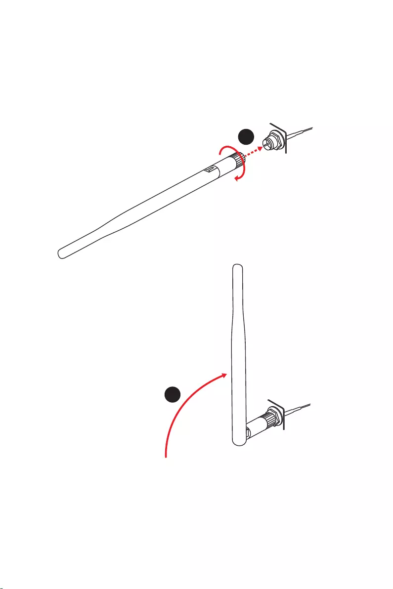
16
1.
2.
1
2

17
JUSB2
SYS_FAN5
SYS_FAN4
SYS_FAN3
SYS_FAN2
JBAT1
JTBT1
JTPM1
JRGB1
56
M2_3
JCI1
M2_1
SYS_FAN1
JDASH1
JUSB4
JUSB3
JUSB1
CPU_FAN1
SYS_FAN6
PUMP_FAN1
PCI_E1
PCI_E2
PCI_E3
PCI_E4
CPU_PWR1 JRAINBOW3JSMB1
CPU_PWR2 JRAINBOW2
JAUD1
JFP2
JRAINBOW1
JPWRLED1
LED_SW1
JFP1
ATX_PWR1
DIMMB1
DIMMB2
DIMMA1
M2_2
M2_4
DIMMA2

18

19
DIMMA1 DIMMB1
DIMMA2 DIMMB2
DIMMA2 DIMMA2
DIMMB2
DIMMA1
DIMMA2
DIMMB1
DIMMB2
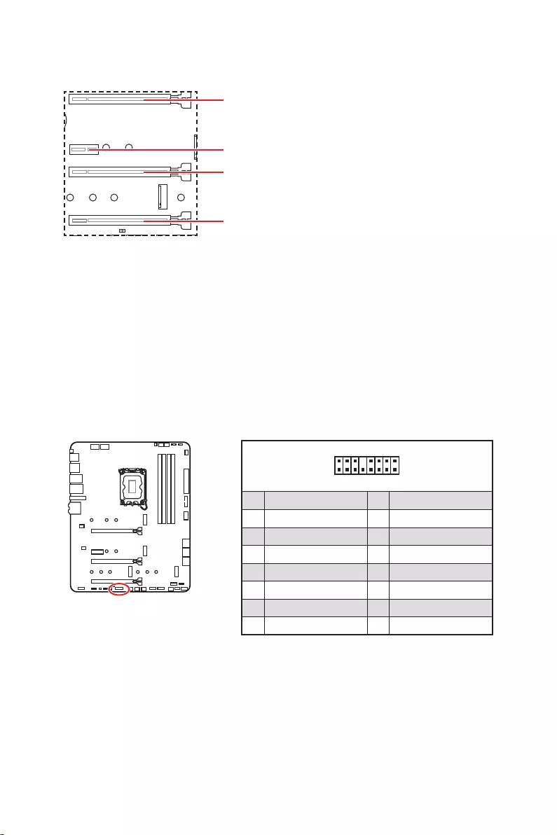
20
: PCI
1
2 16
15
1 TBT_Force_PWR 2 TBT_S0IX_Entry_REQ
3 TBT_CIO_Plug_Event# 4 TBT_S0IX_Entry_ACK
5 SLP_S3#_TBT 6 TBT_PSON_Override_N
7 SLP_S5#_TBT 8 No pin
9 Ground 10 SMBCLK_VSB
11 DG_PEWake 12 SMBDATA_VSB
13 TBT_RTD3_PWR_EN 14 Ground
15 TBT_Card_DET_R# 16 PD_IRQ#

21
M2_1
M2_2
M2_4
M2_3
1.
2.
2
2
2
2
1
1
1
1
11
1
M2_2
M2_3
M2_1
M2_4

22
30º30º
5
6
6
6
66 6
6
4
3
3.
4.
5.
6.
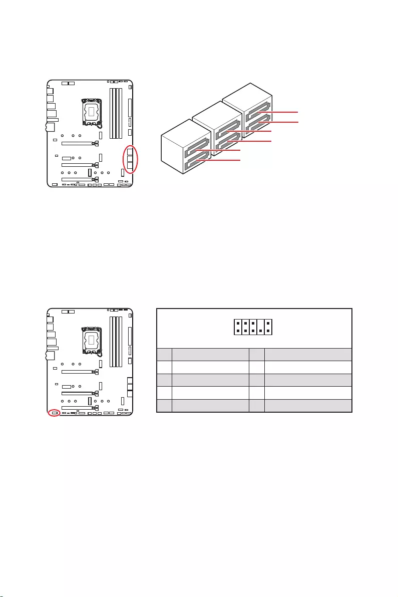
23
SATAA
SATA7
SATA5
SATAB
SATA8
SATA6
1
2 10
9
1 MIC L 2 Ground
3 MIC R 4 NC
5 Head Phone R 6 MIC Detection
7 SENSE_SEND 8 No Pin
9 Head Phone L 10 Head Phone Detection

24
1
2 10
9
+
+
+
+
Power LED
HDD LED Reset Switch
Reserved
Power Switch
JFP1
1 HDD LED + 2 Power LED +
3 4
5 Reset Switch 6 Power Switch
7 Reset Switch 8 Power Switch
9 Reserved 10 No Pin
1
JFP2
+
+
Speaker
Buzzer
1 2 Buzzer +
3 4 Speaker +

25
24
131
12
ATX_PWR1
1 +3.3V 13 +3.3V
2 +3.3V 14
3 Ground 15 Ground
4 +5V 16
5 Ground 17 Ground
6 +5V 18 Ground
7 Ground 19 Ground
8 PWR OK 20 Res
9 5VSB 21 +5V
10 +12V 22 +5V
11 +12V 23 +5V
12 +3.3V 24 Ground
5
4 1
8CPU_PWR1~2
1 Ground 5 +12V
2 Ground 6 +12V
3 Ground 7 +12V
4 Ground 8 +12V
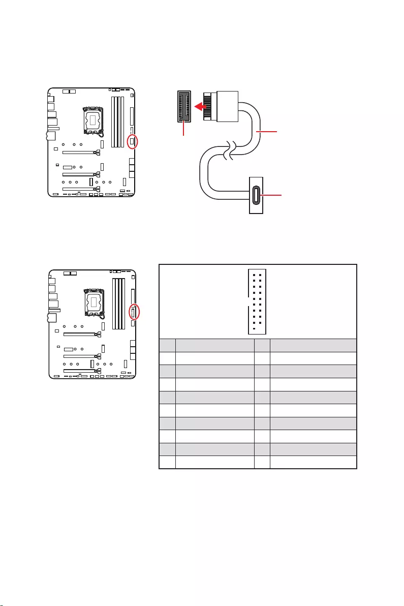
26
1
10 11
20
1 Power 11 USB2.0+
2 USB3_RX_DN 12
3 USB3_RX_DP 13 Ground
4 Ground 14 USB3_TX_C_DP
5 USB3_TX_C_DN 15 USB3_TX_C_DN
6 USB3_TX_C_DP 16 Ground
7 Ground 17 USB3_RX_DP
8 18 USB3_RX_DN
9 USB2.0+ 19 Power
10 Ground 20 No Pin
JUSB4

27
1
2 10
9
1 VCC 2 VCC
3 4
5 USB0+ 6 USB1+
7 Ground 8 Ground
9 No Pin 10 NC
1
2 12
11
1 SPI Power 2 SPI Chip Select
3
Master In Slave Out (SPI Data)
4
Master Out Slave In (SPI Data)
5 Reserved 6 SPI Clock
7 Ground 8 SPI Reset
9 Reserved 10 No Pin
11 Reserved 12 Interrupt Request
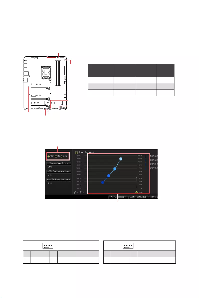
28
PWM
CPU_FAN1 2A 24W
PUMP_FAN1 3A 36W
SYS_FAN1~6 1A 12W
1
1 Ground 2 +12V
3 Sense 4 Speed Control Signal
1
1 Ground 2 Voltage Control
3 Sense 4 NC
SYS_FAN1
SYS_FAN3
SYS_FAN5
SYS_FAN4
PUMP_FAN1
CPU_FAN1
SYS_FAN2
SYS_FAN6

29
1.
2.
3.
4. Enabled
5. F10EnterYes
6.
1.
2. Reset
3. F10EnterYes
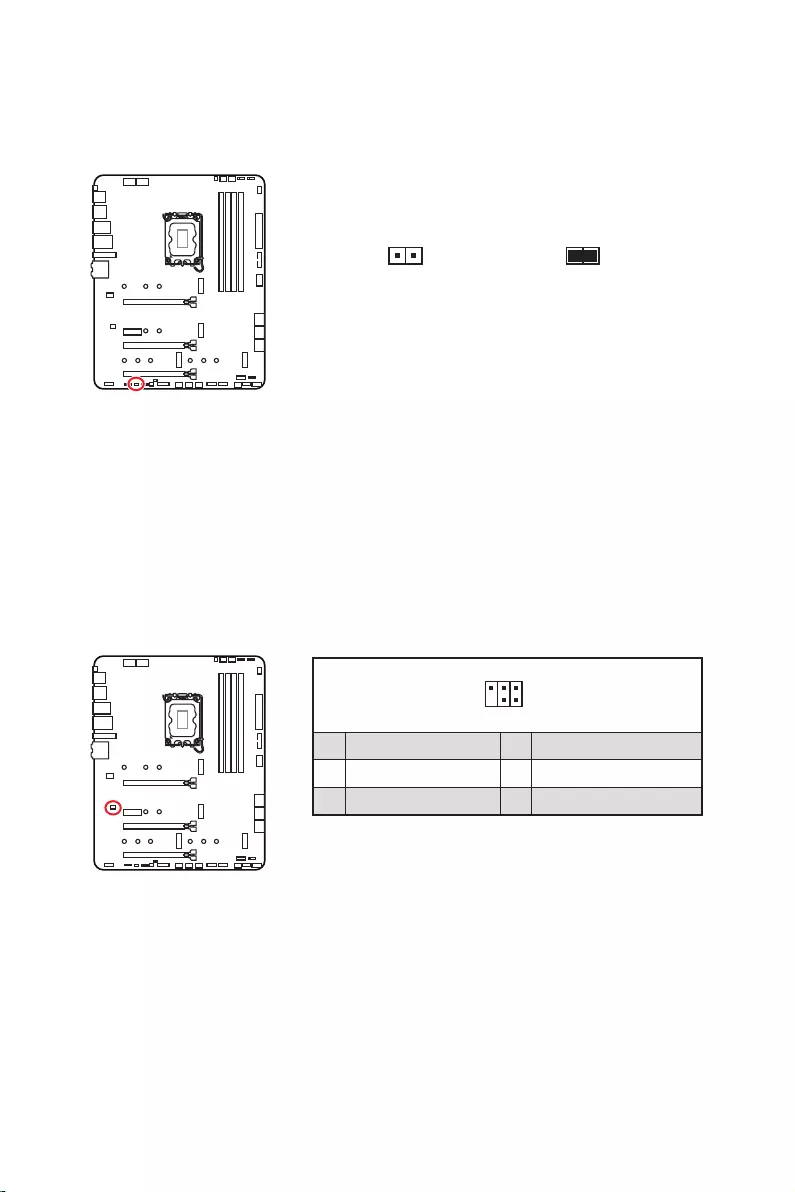
30
1.
2.
3.
4.
1
2 6
5
1 No Pin 2 NC
3 MCU_SMB_SCL_M 4 MCU_SMB_SDA_M
5 VCC5 6 Ground
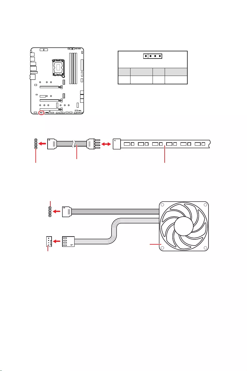
31
1
GRB
1
1 +12V 2 G
3 R 4 B
1
1
GRB
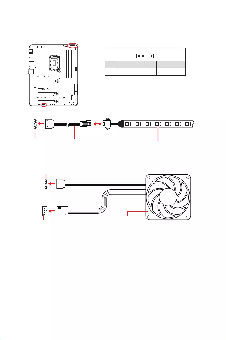
32
1
1
1
D
+5V
JRAINBOW
1
1 +5V 2 Data
3 No Pin 4 Ground
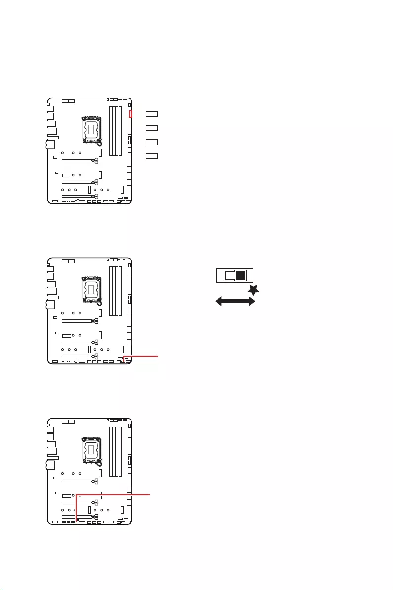
33
LED_SW1
LED_OFF LED_ON

34
1.
2.
3. Restart
4. F11
5.
6.
7.
1.
2.
3.
Run DVDSetup.exe
DVDSetup.exe
4.
5. Install
6.
7.
8.
http://download.msi.com/manual/mb/MSICENTERCS.pdf

35
1.
2.
Delete
3.

36
MenuDelete
F1
F2
F3
F4
F5
F6
F7
F8
F9
F10
F12
http://download.msi.com/manual/mb/Intel600BIOSsc.pdf
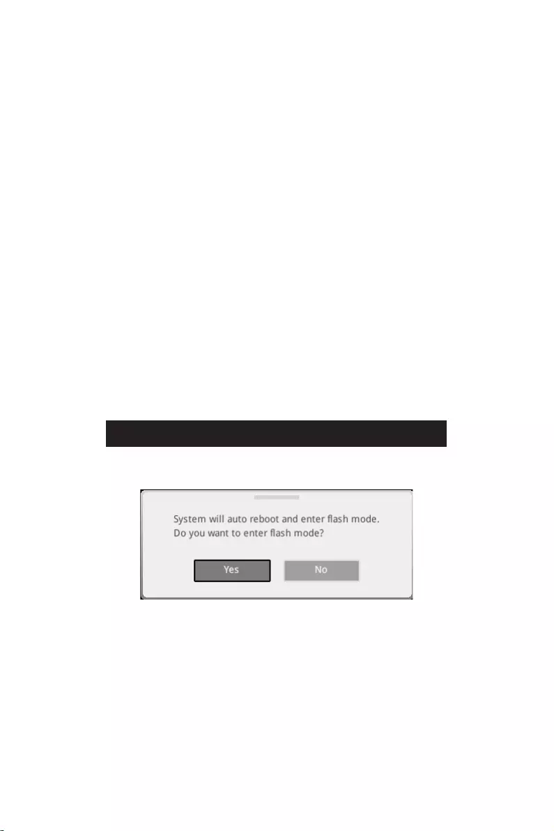
37
F6
1.
2.
3.
Yes
DelYes
4.
5. Yes
6.

38
1. Support
2.
3. Install
4.
5.
6.
1.
2.
3.
4.
5.
6.

i
This equipment has been tested and found to comply with the limits
for a Class B digital device, pursuant to part 15 of the FCC rules. These
limits are designed to provide reasonable protection against harmful
interference in a residential installation. This equipment generates,
uses and radiates radio frequency energy, and, if not installed and
used in accordance with the instructions, may cause harmful interference to radio
communications. However, there is no guarantee that interference will not occur in a
particular installation. If this equipment does cause harmful interference to radio or
television reception, which can be determined by turning the equipment off and on, the
user is encouraged to try to correct the interference by one or more of the following
measures:
Reorient or relocate the receiving antenna.
Increase the separation between the equipment and receiver.
Connect the equipment into an outlet on a circuit different from that to which the
receiver is connected.
The changes or modifications not expressly approved by the party responsible for
compliance could void the user’s authority to operate the equipment.
Shield interface cables and AC power cord, if any, must be used in order to comply
with the emission limits.
This device complies with part 15 of the FCC Rules. Operation is subject to the
following two conditions:
This device may not cause harmful interference.
This device must accept any interference received, including interference that may
cause undesired operation.
901 Canada Court, City of Industry, CA 91748, USA
www.msi.com

ii
Products bearing the CE marking comply with one or more of the
following EU Directives as may be applicable:
RED 2014/53/EU
Low Voltage Directive 2014/35/EU
EMC Directive 2014/30/EU
RoHS Directive 2011/65/EU
ErP Directive 2009/125/EC
Compliance with these directives is assessed using applicable European Harmonized
Standards.
Son.
This product incorporates a radio transmitting and receiving device. For computers
in normal use, a separation distance of 20 cm ensures that radio frequency exposure
levels comply with EU requirements. Products designed to be operated at closer
proximities, such as tablet computers, comply with applicable EU requirements in
typical operating positions. Products can be operated without maintaining a separation
distance unless otherwise indicated in instructions specific to the product.
: IEEE 802.11x wireless LAN with 5.15~5.35 GHz frequency
band is restricted for indoor use only in all European Union member
states, EFTA (Iceland, Norway, Liechtenstein), and most other European
countries (e.g., Switzerland, Turkey, Republic of Serbia). Using this WLAN
application outdoors might lead to interference issues with existing radio
services.
Frequency Range:
2412~2484MHz
5150~5350MHz (RLAN 1)
5470~5725MHz (RLAN 2)
5725~5875MHz (RLAN 3)
5875~5925MHz (RLAN 4)
5925~6425MHz
Max Power Level: 2.4 GHz: 20dBm; 5 GHz: 23dBm; 6 GHz: 23dBm

iii
This device is restricted to indoor use when operating in the 2.4GHz, 5GHz, 6GHz
frequency band.
Cet appareil doit être utilisé à l’intérieur.
This device complies with with Innovation, Science and Economic Development
(1) this device may not cause interference, and (2) this device must accept any
interference, including interference that may cause undesired operation of the device.
This equipment incorporates a radio transmitting and receiving device. In normal use,
a separation distance of 20 cm ensures that radio frequency exposure levels comply
with the Australian and New Zealand Standards.
iv
Batteries, battery packs, and accumulators should not be disposed of as
unsorted household waste. Please use the public collection system to
return, recycle, or treat them in compliance with the local regulations.
For better environmental protection, waste batteries should be collected
separately for recycling or special disposal.
The button cell battery may contain perchlorate material and requires
special handling when recycled or disposed of in California.
For further information please visit:
http://www.dtsc.ca.gov/hazardouswaste/perchlorate/
: There is a risk of explosion, if battery is incorrectly replaced. Replace only
with the same or equivalent type recommended by the manufacturer.
In compliance with chemical substances regulations, such as the EU REACH
Regulation (Regulation EC No. 1907/2006 of the European Parliament and the
Council), MSI provides the information of chemical substances in products at:
https://csr.msi.com/global/index
Environmental Policy
The product has been designed to enable proper reuse of parts and
recycling and should not be thrown away at its end of life.
Users should contact the local authorized point of collection for recycling
Visit the MSI website and locate a nearby distributor for further recycling
information.
Users may also reach us at gpcontdev@msi.com for information regarding proper
Statement
To protect the global environment and as an environmentalist, MSI must
remind you that…
Under the European Union (“EU”) Directive on Waste Electrical and
Electronic Equipment, Directive 2002/96/EC, which takes effect on August
13, 2005, products of “electrical and electronic equipment” cannot be

v
discarded as municipal wastes anymore, and manufacturers of covered electronic
equipment will be obligated to take back such products at the end of their useful life.
branded products that are sold into the EU. You can return these products to local
collection points.
Hinweis von MSI zur Erhaltung und Schutz unserer Umwelt
beauftragt, die in die Europäische Union in Verkehr gebrachten Produkte, am Ende
seines Lebenszyklus zurückzunehmen. Bitte entsorgen Sie dieses Produkt zum
gegebenen Zeitpunkt ausschliesslich an einer lokalen Altgerätesammelstelle in Ihrer
Nähe.
En tant qu’écologiste et afin de protéger l’environnement, MSI tient à rappeler ceci…
Au sujet de la directive européenne (EU) relative aux déchets des équipement
électriques et électroniques, directive 2002/96/EC, prenant effet le 13 août 2005,
que les produits électriques et électroniques ne peuvent être déposés dans les
décharges ou tout simplement mis à la poubelle. Les fabricants de ces équipements
seront obligés de récupérer certains produits en fin de vie. MSI prendra en compte
cette exigence relative au retour des produits en fin de vie au sein de la communauté
européenne. Par conséquent vous pouvez retourner localement ces matériels dans
les points de collecte.
MSI como empresa comprometida con la protección del medio ambiente, recomienda:
Bajo la directiva 2002/96/EC de la Unión Europea en materia de desechos y/o
equipos electrónicos, con fecha de rigor desde el 13 de agosto de 2005, los productos
clasificados como “eléctricos y equipos electrónicos” no pueden ser depositados en
los contenedores habituales de su municipio, los fabricantes de equipos electrónicos,
están obligados a hacerse cargo de dichos productos al termino de su período de vida.
MSI estará comprometido con los términos de recogida de sus productos vendidos en

vi
la Unión Europea al final de su periodo de vida. Usted debe depositar estos productos
en el punto limpio establecido por el ayuntamiento de su localidad o entregar a una
empresa autorizada para la recogida de estos residuos.
Om het milieu te beschermen, wil MSI u eraan herinneren dat….
De richtlijn van de Europese Unie (EU) met betrekking tot Vervuiling van Electrische
en Electronische producten (2002/96/EC), die op 13 Augustus 2005 in zal gaan kunnen
niet meer beschouwd worden als vervuiling. Fabrikanten van dit soort producten
worden verplicht om producten retour te nemen aan het eind van hun levenscyclus.
MSI zal overeenkomstig de richtlijn handelen voor de producten die de merknaam MSI
dragen en verkocht zijn in de EU. Deze goederen kunnen geretourneerd worden op
lokale inzamelingspunten.
SRPSKI
sredini, MSI mora da vas podesti da…
Direktiva 2002/96/EC, koja stupa na snagu od 13. Avgusta 2005, proizvodi koji spadaju
kojima je istekao vek trajanja, koji imaju MSI oznaku i koji su prodati u EU. Ove
produktów elektrycznych i elektronicznych (Dyrektywa 2002/96/EC), która wchodzi w
wyznaczonych punktach zbiorczych.
2002/96/EC platné od 13. srpna 2005 je zakázáno likvidovat “elektrické a elektronické

vii
az MSI emlékezteti Önt, hogy …
elektronikus berendezések hulladékairól szóló 2002/96/EK irányelve szerint az
hulladékként, és az ilyen elektronikus berendezések gyártói kötelessé válnak az
ilyen termékek visszavételére azok hasznos élettartama végén. Az MSI betartja
a termékvisszavétellel kapcsolatos követelményeket az MSI márkanév alatt az
Per proteggere l’ambiente, MSI, da sempre amica della natura, ti ricorda che….
In base alla Direttiva dell’Unione Europea (EU) sullo Smaltimento dei Materiali
Elettrici ed Elettronici, Direttiva 2002/96/EC in vigore dal 13 Agosto 2005, prodotti
appartenenti alla categoria dei Materiali Elettrici ed Elettronici non possono più
essere eliminati come rifiuti municipali: i produttori di detti materiali saranno obbligati
a ritirare ogni prodotto alla fine del suo ciclo di vita. MSI si adeguerà a tale Direttiva
ritirando tutti i prodotti marchiati MSI che sono stati venduti all’interno dell’Unione
Europea alla fine del loro ciclo di vita. È possibile portare i prodotti nel più vicino punto
di raccolta
and prohibits use of lead, mercury, hexavalent chromium, polybrominated biphenyls
or polybrominated diphenyl ethers in concentrations exceeding 0.1 weight % and 0.01
weight % for cadmium, except for the exemptions set in Schedule 2 of the Rule.
viii
(Pb)
(Hg)
(Cd)
(Cr(VI))
(PBB)
(PBDE)
(Pb)
(Hg)
(Cd)
(Cr+6)
(PBB)
(PBDE)

ix
other marks and names mentioned may be trademarks of their respective owners. No
warranty as to accuracy or completeness is expressed or implied. MSI reserves the
right to make changes to this document without prior notice.
If a problem arises with your system and no solution can be obtained from the user
guide, please contact your place of purchase or local distributor. Alternatively, please
try the following help resources for further guidance.
Visit the MSI website for technical guide, BIOS updates, driver updates, and other
information: http://www.msi.com
Register your product at: http://register.msi.com
Version 3.0, 2021/10, First release.
Version 3.1, 2022/01, update list.
MSI MPG Z690 Edge WIFI DDR4 Specification
The MSI MPG Z690 Edge WIFI DDR4 is a high-performance ATX motherboard tailored for Intel’s 12th generation Alder Lake processors, supporting the LGA 1700 socket. Designed to accommodate DDR4 memory, it offers four DIMM slots with a maximum capacity of 128GB and supports speeds up to 5200 MHz (OC). The board features robust power delivery with a 16+1+1 Duet Rail Power System, ensuring stable performance for overclocking enthusiasts.
Connectivity is a standout feature with integrated Wi-Fi 6E and Bluetooth 5.2, providing fast and reliable wireless networking capabilities. The motherboard also includes a 2.5G LAN port for high-speed wired internet connectivity. Storage options are versatile, featuring six SATA 6Gb/s ports and four M.2 slots, each equipped with MSI’s M.2 Shield Frozr to prevent thermal throttling.
For expansion, the MPG Z690 Edge WIFI DDR4 includes three PCIe x16 slots, with support for PCIe 5.0, ensuring compatibility with the latest graphics cards and providing future-proofing for upcoming technologies. The board supports multi-GPU setups, making it suitable for gaming and intensive computing tasks.
Onboard audio is powered by the Realtek ALC4080 codec, offering high-quality 7.1-channel surround sound for an immersive audio experience. The rear I/O panel includes multiple USB ports, including USB 3.2 Gen 2×2 Type-C, HDMI, and DisplayPort outputs, offering extensive connectivity options for peripherals and displays.
The design incorporates RGB lighting with MSI Mystic Light support, allowing customizable illumination to match any gaming setup. Comprehensive cooling solutions, including multiple fan and pump headers, ensure optimal thermal management. The MSI MPG Z690 Edge WIFI DDR4 combines cutting-edge technology with robust features, making it a strong contender for gamers and PC enthusiasts seeking performance and versatility.
MSI MPG Z690 Edge WIFI DDR4 F.A.Q.
To update the BIOS, visit the MSI support website, download the latest BIOS version, and use the M-Flash utility in the BIOS setup to install it. Ensure your system is stable and avoid power interruptions during the update.
Check all power connections, ensure RAM and CPU are seated properly, clear the CMOS, and remove any unnecessary peripherals. If the issue persists, consult the motherboard’s debug LEDs for error codes.
Enter the BIOS setup by pressing the ‘Delete’ key during boot, navigate to the overclocking settings, and enable XMP to allow your RAM to run at its rated speed. Save and exit the BIOS.
Use the available SATA ports for traditional drives and the M.2 slots for NVMe SSDs. Ensure that M.2 slots are configured correctly in the BIOS if using RAID or special configurations.
Ensure the WiFi antennas are properly connected, update the network drivers from the MSI website, and check network settings in the BIOS. If using Ethernet, verify the cable and router connections.
To reset the BIOS, power off the system, unplug it, and use the CMOS jumper on the motherboard or remove the battery for a few minutes. Reinstall the battery or reset the jumper, then power the system back on.
The motherboard offers advanced voltage regulation, DDR4 memory overclocking, CPU frequency adjustments, and comprehensive BIOS settings for fine-tuning performance.
Access the BIOS and navigate to the hardware monitor section to configure fan curves based on temperature readings. Alternatively, use the MSI Dragon Center software for more intuitive control.
Yes, the motherboard is designed to support Intel’s 12th-gen Alder Lake processors. Ensure your BIOS is up to date for the best compatibility and performance.
Install additional case fans, ensure proper cable management for better airflow, and consider using aftermarket CPU coolers or liquid cooling solutions for enhanced thermal management.
Table of Contents
- MSI MPG Z690 EDGE WIFI DDR4 Motherboard
- Installing a Processor
- Installing DDR4 memory
- **Connecting the Front Panel Header
- Installing the Motherboard
- Power On
- Safety Information
- Case stand-off notification
- Specifications
- Package contents
- Rear I/O Panel
- Overview of Components
- RGB LED Strip Connection
- Onboard LEDs
- Installing OS, Drivers & MSI Center
- MSI Center
- UEFI BIOS
- Entering BIOS Setup
- Updating BIOS
- Updating the BIOS with MSI Center
- Regulatory Notices
- Battery Information
- References
- Read User Manual Online (PDF format)
- Download This Manual (PDF format)
MSI MPG Z690 EDGE WIFI DDR4 Motherboard

Quick Start
Thank you for purchasing the MSI® motherboard. This Quick Start section
provides demonstration diagrams about how to install your computer. Some of
the installations also provide video demonstrations. Please link to the URL to
watch it with the web browser on your phone or tablet. You may have even link
to the URL by scanning the QR code.
Installing a Processor

Youtube
https://youtu.be/KMf9oIDsGes
Installing DDR4 memory


**
Installing the Motherboard

Connecting the Power Connectors

Installing SATA Drives

Installing a Graphics Card

Connecting Peripheral Devices

Power On

Safety Information
- The components included in this package are prone to damage from electrostatic discharge (ESD). Please adhere to the following instructions to ensure successful computer assembly.
- Ensure that all components are securely connected. Loose connections may cause the computer to not recognize a component or fail to start.
- Hold the motherboard by the edges to avoid touching sensitive components.
- It is recommended to wear an electrostatic discharge (ESD) wrist strap when handling the motherboard to prevent electrostatic damage. If an ESD wrist strap is not available, discharge yourself of static electricity by touching another metal object before handling the motherboard.
- Store the motherboard in an electrostatic shielding container or on an anti-static pad whenever the motherboard is not installed.
- Before turning on the computer, ensure that there are no loose screws or metal components on the motherboard or anywhere within the computer case.
- Do not boot the computer before installation is completed. This could cause permanent damage to the components as well as injury to the user.
- If you need help during any installation step, please consult a certified computer technician.
- Always turn off the power supply and unplug the power cord from the power outlet before installing or removing any computer component.
- Keep this user guide for future reference.
- Keep this motherboard away from humidity.
- Make sure that your electrical outlet provides the same voltage as is indicated on the PSU, before connecting the PSU to the electrical outlet.
- Place the power cord such a way that people can not step on it. Do not place anything over the power cord.
- All cautions and warnings on the motherboard should be noted.
- If any of the following situations arises, get the motherboard checked by service personnel:
- Liquid has penetrated into the computer.
- The motherboard has been exposed to moisture.
- The motherboard does not work well or you can not get it work according to user guide.
- The motherboard has been dropped and damaged.
- The motherboard has obvious sign of breakage.
- Do not leave this motherboard in an environment above 60°C (140°F), it may damage the motherboard.
Case stand-off notification
To prevent damage to the motherboard, any unnecessary mounting stand-off
between the motherboard circuits and the computer case is prohibited. The Case
standoff keep out zone signs will be marked on the backside of motherboard (as
shown below) to serve as a warning to user.
Avoid collision notification
Protective paint is printed around each screw hole to prevent parts from being
scratched.

Specifications
CPU
| ∙ Supports 12th Gen Intel® Core™, Pentium® Gold and Celeron® Processors*
∙ Processor socket LGA1700
- Please go to www.msi.com to get the newest support status as new processors are released.
—|—
Chipset| Intel® Z690 Chipset
Memory
| ∙ 4x DDR4 memory slots, support up to 128GB*
∙ Supports 1R 2133/ 2666/ 2933/ 3200 MHz (by JEDEC & POR)*
∙ Max overclocking frequency:
▪ 1DPC 1R Max speed up to 5200+ MHz
▪ 1DPC 2R Max speed up to 4800+ MHz
▪ 2DPC 1R Max speed up to 4400+ MHz
▪ 2DPC 2R Max speed up to 4000+ MHz
∙ Supports Dual-Channel mode
∙ Supports non-ECC, un-buffered memory
∙ Supports Intel® Extreme Memory Profile (XMP)
*Please refer to www.msi.com for more information on compatible memory
Expansion Slot
| ∙ 3x PCIe x16 slots
▪ PCI_E1 slot (From CPU)
▫ Supports PCIe 5.0 x16
▪ PCI_E3 & PCI_E4 slots (From Z690 chipset)
▫ Supports PCIe 3.0 x4
∙ 1x PCIe 3.0 x1 slot (From Z690 chipset)
Multi-GPU| ∙ Supports AMD® CrossFire™ Technology
Onboard Graphics
| ∙ 1x HDMI 2.1 with HDR port, supports a maximum resolution of 4K 60Hz*/**
∙ 1x DisplayPort 1.4 port with HBR3, supports a maximum resolution of 4K
60Hz*/**
*Available only on processors featuring integrated graphics.
** Graphics specifications may vary depending on the Processor installed.
Storage
| ∙ 6x SATA 6Gb/s ports
▪ SATA5~8 (From Z690 Chipset)
▪ SATAA~B (From ASMedia ASM1061)
∙ 4x M.2 slots (Key M)
▪ M2_1 slot (From CPU)
▫ Supports PCIe 4.0 x4
▫ Supports 2260/ 2280/ 22110 storage devices
▪ M2_2 slot (From Z690 Chipset)
▫ Supports PCIe 4.0 x4
▫ Supports 2260/ 2280 storage devices
▪ M2_3 slot (From Z690 Chipset)
▫ Supports PCIe 4.0 x4
▫ Supports SATA 6Gb/s
▫ Supports 2242/ 2260/ 2280 storage devices
▪ M2_4 slot (From Z690 Chipset)
▫ Supports PCIe 4.0 x4
▫ Supports SATA 6Gb/s
▫ Supports 2242/ 2260/ 2280 storage devices
∙ M2_2~4 support Intel® Optane™ Memory
∙ Supports Intel® Smart Response Technology for Intel Core™ processors
—|—
RAID
| ∙ Supports RAID 0, RAID 1, RAID 5 and RAID 10 for SATA storage devices*
∙ Supports RAID 0, RAID 1 and RAID 5 for M.2 PCIe storage devices
- SATAA & SATAB do not support RAID function.
Audio
| ∙ Realtek® ALC4080
▪ 7.1-Channel High Definition Audio
▪ Supports S/PDIF output
USB
| ∙ Intel® Z690 Chipset
▪ 1x USB 3.2 Gen 2×2 20Gbps Type-C port on the back
panel
▪ 6x USB 3.2 Gen 2 10Gbps ports (1 Type-C internal connector and 5 Type-A
ports on the back panel)
▪ 2x USB 2.0 Type-A ports on the back panel
▪ 2x USB 3.2 Gen 1 5Gbps ports available through the internal USB connector
∙ USB Hub-GL850G
▪ 4x USB 2.0 ports available through the internal USB connectors
—|—
LAN| ∙ 1x Intel® I225V 2.5Gbps LAN controller
Wireless LAN &
Bluetooth®
| Intel® Wi-Fi 6
∙ The Wireless module is pre-installed in the M.2 (Key-E)
slot
∙ Supports MU-MIMO TX/RX, 2.4GHz/ 5GHz (160MHz) up to
2.4Gbps
∙ Supports 802.11 a/ b/ g/ n/ ac/ ax
∙ Supports Bluetooth® 5.2
Back Panel
Connectors
| ∙ 1x Flash BIOS button
∙ 2x USB 2.0 ports
∙ 1x DisplayPort
∙ 1x HDMI port
∙ 5x USB 3.2 Gen 2 10Gbps Type-A ports
∙ 1x USB 3.2 Gen 2×2 20Gbps Type-C port
∙ 1x 2.5Gbps LAN (RJ45) port
∙ 2x Wi-Fi Antenna connectors
∙ 5x audio jacks
∙ 1x Optical S/PDIF Out connector
Internal Connectors
| ∙ 1x 24-pin ATX main power connector
∙ 2x 8-pin ATX 12V power connectors
∙ 6x SATA 6Gb/s connectors
∙ 4x M.2 slots (M-Key)
∙ 1x USB 3.2 Gen 2 10Gbps Type-C port
∙ 1x USB 3.2 Gen 1 5Gbps connector (supports additional 2 USB 3.2 Gen 1 5Gbps
ports)
∙ 2x USB 2.0 connectors (supports additional 4 USB 2.0 ports)
∙ 1x 4-pin CPU fan connector
∙ 1x 4-pin water-pump fan connector
∙ 6x 4-pin system fan connectors
∙ 1x Front panel audio connector
∙ 2x System panel connectors
∙ 1x Chassis Intrusion connector
∙ 1xTPM module connector
∙ 1x Clear CMOS jumper
∙ 1x Tuning controller connector
∙ 1x TBT connector (Supports RTD3)
—|—
LED Features
| ∙ 1x 4-pin RGB LED connector
∙ 3x 3-pin RAINBOW LED connectors
∙ 1x EZ LED Control switch
∙ 4x EZ Debug LED
I/O Controller| NUVOTON NCT6687D Controller Chip
Hardware Monitor
| ∙ CPU/ System/ Chipset temperature detection
∙ CPU/ System/ Pump fan speed detection
∙ CPU/ System/ Pump fan speed control
Form Factor| ∙ ATX Form Factor
∙ 12 in. x 9.6 in. (30.5 cm x 24.4 cm)
BIOS Features
| ∙ 1x 256 Mb flash
∙ UEFI AMI BIOS
∙ ACPI 6.4, SMBIOS 3.4
∙ Multi-language
—|—
Software
| ∙ Drivers
∙ MSI Center
∙ Intel® Extreme Tuning Utility
∙ MSI APP Player (BlueStacks)
∙ Open Broadcaster Software (OBS)
∙ CPU-Z MSI GAMING
∙ Google Chrome™, Google Toolbar, Google Drive
∙ Norton™ Internet Security Solution
| ∙ Gaming Mode
| ∙ Smart Priority
| ∙ Gaming Highlight
| ∙ LAN Manager
| ∙ Mystic Light
| ∙ Ambient Devices
MSI Center Features
| ∙ Frozr AI Cooling
∙ User Scenario
∙ True Color
| ∙ Live Update
| ∙ Hardware Monitoring
| ∙ Super Charger
| ∙ Speed Up
| ∙ Smart Image Finder
| ∙ MSI Companion
Special Features
| ∙ Audio
▪ Audio Boost 5
∙ Network
▪ 2.5G LAN
▪ LAN Manager
▪ Intel® WiFi
∙ Cooling
▪ All Aluminum Design
▪ Heat-pipe Design
▪ Extended Heatsink Design
▪ M.2 Shield Frozr
▪ 7W/mK MOSFET thermal pad
▪ Choke thermal pad
▪ Pump Fan
▪ Smart Fan Control
∙ LED
▪ Mystic Light
▪ Mystic Light Extension (RAINBOW/RGB)
▪ Mystic Light SYNC
▪ Ambient Devices Support
—|—
Special Features
| ∙ Performance
▪ Lightning Gen 5 PCI-E Slot
▪ Lightning Gen 4 M.2
▪ Multi GPU – CrossFire Technology
▪ Memory Boost
▪ Core Boost
▪ Game Boost
▪ Lightning USB 20G
▪ USB 3.2 Gen 2 10G
▪ USB with Type A+C
▪ Front USB Type-C
▪ Dual CPU Power
▪ Server PCB
▪ 2oz Copper thickened PCB
∙ Protection
▪ PCI-E Steel Armor
▪ Pre-installed I/O Shielding
∙ Experience
▪ MSI Center
▪ Click BIOS 5
▪ EZ M.2 Clip
▪ Frozr AI Cooling
▪ Flash BIOS Button
▪ EZ LED Control
▪ EZ DEBUG LED
▪ App player
▪ Tile
—|—
Package contents
| Motherboard | MPG Z690 EDGE WIFI DDR4 |
|---|---|
| Documentation | Quick installation guide |
| Application | USB drive with drivers & utilities |
Cable
| SATA 6G cables (2 cables/pack)| 1
LED JRGB Y cable| 1
LED JRAINBOW cable| 1
Accessories
| Wi-Fi Antenna| 1
Case Badge| 1
EZ M.2 clip (1 set/pack)| 2
MPG sticker| 1
SATA cable stickers| 1
Product registration card| 1
Gift| Small screwdriver set| 1
Small brush| 1
Please check the contents of your motherboard package. It should contain:
Important
If any of the above items are damaged or missing, please contact your
retailer.
Rear I/O Panel

Flash BIOS Port/ Button – Please refer to page 38 for Updating BIOS with Flash
BIOS Button.
LAN Port LED Status Table

Audio Ports Configuration

Realtek Audio Console
After Realtek Audio Console is installed. You can use it to change sound
settings to get better sound experience.

- Device Selection – allows you to select a audio output source to change the related options. The check sign indicates the devices as default.
- Application Enhancement – the array of options will provide you a complete guidance of anticipated sound effect for both output and input device.
- Main Volume – controls the volume or balance the right/left side of the speakers that you plugged in front or rear panel by adjust the bar.
- Jack Status – depicts all render and capture devices currently connected with your computer.
- Connector Settings – configures the connection settings.
Auto popup dialog
When you plug into a device at an audio jack, a dialogue window will pop up
asking you which device is current connected.
Each jack corresponds to its default setting as shown on the next page.
Important
The pictures above for reference only and may vary from the product you
purchased.
Audio jacks to headphone and microphone diagram

Audio jacks to stereo speakers diagram

Audio jacks to 7.1-channel speakers diagram

Installing antennas
- Screw the antennas tight to the antenna connectors as shown below.
- Orient the antennas.

Overview of Components

CPU Socket

Introduction to the LGA1700 CPU
The surface of the LGA1700 CPU has four notches and a golden triangle to
assist in correctly lining up the CPU for motherboard placement. The golden
triangle is the Pin 1 indicator.
Important
- Always unplug the power cord from the power outlet before installing or removing the CPU.
- Please retain the CPU protective cap after installing the processor. MSI will deal with Return Merchandise Authorization (RMA) requests if only the motherboard comes with the protective cap on the CPU socket.
- When installing a CPU, always remember to install a CPU heatsink. A CPU heatsink is necessary to prevent overheating and maintain system stability.
- Confirm that the CPU heatsink has formed a tight seal with the CPU before booting your system.
- Overheating can seriously damage the CPU and motherboard. Always make sure the cooling fans work properly to protect the CPU from overheating. Be sure to apply an even layer of thermal paste (or thermal tape) between the CPU and the heatsink to enhance heat dissipation.
- Whenever the CPU is not installed, always protect the CPU socket pins by covering the socket with the plastic cap.
- If you purchased a separate CPU and heatsink/ cooler, Please refer to the documentation in the heatsink/ cooler package for more details about installation.
- This motherboard is designed to support overclocking. Before attempting to overclock, please make sure that all other system components can tolerate overclocking. Any attempt to operate beyond product specifications is not recommended. MSI® does not guarantee the damages or risks caused by inadequate operation beyond product specifications.
DIMM Slots

Memory module installation recommendation

Important
- Always insert memory modules in the DIMMA2 slot first.
- To ensure system stability for Dual channel mode, memory modules must be of the same type, number and density.
- Some memory modules may operate at a lower frequency than the marked value when overclocking due to the memory frequency operates dependent on its Serial Presence Detect (SPD). Go to BIOS and find the DRAM Frequency to set the memory frequency if you want to operate the memory at the marked or at a higher frequency.
- It is recommended to use a more efficient memory cooling system for full DIMMs installation or overclocking.
- The stability and compatibility of installed memory module depend on installed CPU and devices when overclocking.
- Please refer www.msi.com for more information on compatible memory.
PCI_E1~4: PCIe Expansion Slots

Important
- If you install a large and heavy graphics card, you need to use a tool such as MSI Gaming Series Graphics Card Bolster to support its weight to prevent deformation of the slot.
- For a single PCIe x16 expansion card installation with optimum performance, using the PCI_E1 slot is recommended.
- When adding or removing expansion cards, always turn off the power supply and unplug the power supply power cable from the power outlet. Read the expansion
card™s documentation to check for any necessary additional hardware or
software changes.
JTBT1: Thunderbolt Add-on Card Connector
This connector allows you to connect the add-on Thunderbolt I/O card.

M2_1~4: M.2 Slots (Key M)
- Intel® RST only supports PCIe M.2 SSD with UEFI ROM.
- M2_2~4 support Intel® Optane™ Memory.
Installing M.2 module
-
Loosen the screws of M.2 SHIELD FROZR heatsink.
-
Remove the M.2 SHIELD FROZR and remove the protective films from the thermal pads.

-
If there is no EZ M.2 Clip installed, please install the supplied EZ M.2 Clip kit in the
M. 2 slot according to your SSD length. -
Insert your M.2 SSD into the M.2 slot at a 30-degree angle.
-
Rotate the EZ M.2 Clip to fix the M.2 SSD.
-
Put the M.2 SHIELD FROZR heatsink back in place and secure it.


SATA5~8 & SATAA~B: SATA 6Gb/s Connectors
These connectors are SATA 6Gb/s interface ports. Each connector can connect to
one SATA device.

Important
- Please do not fold the SATA cable at a 90-degree angle. Data loss may result during transmission otherwise.
- SATA cables have identical plugs on either sides of the cable. However, it is recommended that the flat connector be connected to the motherboard for space saving purposes.
JAUD1: Front Audio Connector
This connector allows you to connect audio jacks on the front panel.

JFP1, JFP2: Front Panel Connectors
These connectors connect to the switches and LEDs on the front panel.

CPU_PWR1~2, ATX_PWR1: Power Connectors
These connectors allow you to connect an ATX power supply.


Important
Make sure that all the power cables are securely connected to a proper ATX
power supply to ensure stable operation of the motherboard.
JUSB4: USB 3.2 Gen 2 Type-C Connector
This connector allows you to connect USB 3.2 Gen 2 10Gbps Type-C connector on
the front panel. The connector possesses a foolproof design. When you connect
the cable, be sure to connect it with the corresponding orientation.

JUSB3: USB 3.2 Gen 1 Connector
This connector allows you to connect USB 3.2 Gen 1 5Gbps ports on the front
panel.

Important
Note that the Power and Ground pins must be connected correctly to avoid
possible damage.
JUSB1~2: USB 2.0 Connectors
These connectors allow you to connect USB 2.0 ports on the front panel.

Important
- Note that the VCC and Ground pins must be connected correctly to avoid possible damage.
- In order to recharge your iPad,iPhone and iPod through USB ports, please install MSI® Center utility.
JTPM1: TPM Module Connector
This connector is for TPM (Trusted Platform Module). Please refer to the TPM
security platform manual for more details and usages.

CPU_FAN1, PUMP_FAN1, SYS_FAN1~6: Fan Connectors
Fan connectors can be classified as PWM (Pulse Width Modulation) Mode or DC
Mode. PWM Mode fan connectors provide constant 12V output and adjust fan speed
with speed control signal. DC Mode fan connectors control fan speed by
changing voltage. The auto mode fan connectors can automatically detect PWM
and DC mode. However, you can follow the instruction below to adjust the fan
connector to PWM or DC Mode manually.

Switching fan mode and adjusting fan speed
You can switch between PWM mode and DC mode and adjust fan speed in BIOS >
HARDWARE MONITOR.
Important
Make sure fans are working properly after switching the PWM/ DC mode.

Pin definition of fan connectors

JCI1: Chassis Intrusion Connector
This connector allows you to connect the chassis intrusion switch cable.

Using chassis intrusion detector
- Connect the JCI1 connector to the chassis intrusion switch/ sensor on the chassis.
- Close the chassis cover.
- Go to BIOS > SETTINGS > Security > Chassis Intrusion Configuration.
- Set Chassis Intrusion to Enabled.
- Press F10 to save and exit and then press the Enter key to select Yes.
- Once the chassis cover is opened again, a warning message will be displayed on screen when the computer is turned on.
Resetting the chassis intrusion warning
- Go to BIOS > SETTINGS > Security > Chassis Intrusion Configuration.
- Set Chassis Intrusion to Reset.
- Press F10 to save and exit and then press the Enter key to select Yes.
JBAT1: Clear CMOS (Reset BIOS) Jumper
There is CMOS memory onboard that is external powered from a battery located
on the motherboard to save system configuration data. If you want to clear the
system configuration, set the jumpers to clear the CMOS memory.

Resetting BIOS to default values
- Power off the computer and unplug the power cord.
- Use a jumper cap to short JBAT1 for about 5-10 seconds.
- Remove the jumper cap from JBAT1.
- Plug the power cord and Power on the computer.
JDASH1 : Tuning Controller connector
This connector is used to connect an optional Tuning Controller module.

JRGB1: RGB LED connector
The JRGB connector allows you to connect the 5050 RGB LED strips 12V.

RGB LED Strip Connection

RGB LED Fan Connection

- The JRGB connector supports up to 2 meters continuous 5050 RGB LED strips (12V/G/R/B) with the maximum power rating of 3A (12V).
- Always turn off the power supply and unplug the power cord from the power outlet before installing or removing the RGB LED strip.
- Please use MSI’s software to control the extended LED strip.
JRAINBOW1~3: Addressable RGB LED connectors
The JRAINBOW connectors allow you to connect the WS2812B Individually
Addressable RGB LED strips 5V.

Addressable RGB LED Strip Connection

Addressable RGB LED Fan Connection

CAUTION
Do not connect the wrong type of LED strips. The JRGB connector and the
JRAINBOW connector provide different voltages, and connecting the 5V LED strip
to the JRGB
connector will result in damage to the LED strip.
Important
-
The JRAINBOW connector supports up to 75 LEDs WS2812B Individually
Addressable RGB LED strips (5V/Data/Ground) with the maximum power rating of
3A (5V). In the case of 20% brightness, the connector supports up to 200 LEDs. -
Always turn off the power supply and unplug the power cord from the power outlet before installing or removing the RGB LED strip.
-
Please use MSI’s software to control the extended LED strip.
Onboard LEDs
EZ Debug LED
These LEDs indicate the debug status of the motherboard.

LED_SW1: EZ LED Control
This switch is used to switch on/ off all the LEDs of motherboard.

JPWRLED1: LED power input
This connector is used by retailers to demonstrate onboard LED lights.

Installing OS, Drivers & MSI Center
Please download and update the latest utilities and drivers at
www.msi.com
Installing Windows 10/ Windows 11
- Power on the computer.
- Insert the Windows 10/ Windows 11 installation disc/ USB into your computer.
- Press the Restart button on the computer case.
- Press F11 key during the computer POST (Power-On Self Test) to get into Boot Menu.
- Select the Windows 10/ Windows 11 installation disc/USB from the Boot Menu.
- Press any key if screen shows Press any key to boot from CD or DVD… message. If not please skip this step.
- Follow the instructions on the screen to install Windows 10/ Windows 11.
Installing Drivers
- Start up your computer in Windows 10/ Windows 11.
- Insert MSI® USB Drive into the USB port.
- Click the Select to choose what happens with this disc pop-up notification, then select Run DVDSetup.exe to open the installer. If you turn off the AutoPlay feature from the Windows Control Panel, you can still manually execute the DVDSetup.exe from the root path of the MSI USB Drive.
- The installer will find and list all necessary drivers in the Drivers/Software tab.
- Click the Install button in the lower-right corner of the window.
- The drivers installation will then be in progress, after it has finished it will prompt you to restart.
- Click OK button to finish.
- Restart your computer.
MSI Center
MSI Center is an application that helps you easily optimize game settings and
smoothly use content creation softwares. It also allows you to control and
synchronize LED light effects on PCs and other MSI products. With MSI Center,
you can customize ideal modes, monitor system performance, and adjust fan
speed.
MSI Center User Guide
- If you would like to know more information about MSI Center, please refer to http://download.msi.com/manual/mb/MSICENTER.pdf or scan the QR code to access.
Important
Functions may vary depending on the product you have.
UEFI BIOS
MSI UEFI BIOS is compatible with UEFI (Unified Extensible Firmware Interface)
architecture. UEFI has many new functions and advantages that traditional BIOS
cannot achieve, and it will completely replace BIOS in the future. The MSI
UEFI BIOS uses UEFI as the default boot mode to take full advantage of the new
chipset’s capabilities.
Important
The term BIOS in this user guide refers to UEFI BIOS unless otherwise noted.
UEFI advantages
- Fast booting – UEFI can directly boot the operating system and save the BIOS self-test process. And also eliminates the time to switch to CSM mode during POST.
- Supports for hard drive partitions larger than 2 TB.
- Supports more than 4 primary partitions with a GUID Partition Table (GPT).
- Supports unlimited number of partitions.
- Supports full capabilities of new devices – new devices may not provide backward compatibility.
- Supports secure startup – UEFI can check the validity of the operating system to ensure that no malware tampers with the startup process.
Incompatible UEFI cases
- 32-bit Windows operating system – this motherboard supports only Windows 10/ Windows 11 64-bit operating system.
- Older graphics card – the system will detect your graphics card. When display a warning message There is no GOP (Graphics Output protocol) support detected in this graphics card.
Important
We recommend that you to replace with a GOP/UEFI compatible graphics card or
using integrated graphics from CPU for having normal function.
How to check the BIOS mode?
- Power on your computer.
- Press Delete key, when the Press DEL key to enter Setup Menu, F11 to enter Boot Menu message appears on the screen during the boot process.
- After entering the BIOS, you can check the BIOS Mode at the top of the screen.
BIOS Setup
The default settings offer the optimal performance for system stability in
normal conditions. You should always keep the default settings to avoid
possible system damage or failure booting unless you are familiar with BIOS.
Important
- BIOS items are continuously update for better system performance. Therefore, the description may be slightly different from the latest BIOS and should be for reference only. You could also refer to the HELP information panel for BIOS item description.
- The BIOS screens, options and settings will vary depending on your system.
Entering BIOS Setup
Press Delete key, when the Press DEL key to enter Setup Menu, F11 to enter
Boot Menu message appears on the screen during the boot process.
Function key
- F1: General Help list
- F2: Add/ Remove a favorite item
- F3: Enter Favorites menu
- F4: Enter CPU Specifications menu
- F5: Enter Memory-Z menu
- F6: Load optimized defaults
- F7: Switch between Advanced mode and EZ mode
- F8: Load Overclocking Profile
- F9: Save Overclocking Profile
- F10: Save Change and Reset*
- F12: Take a screenshot and save it to USB flash drive (FAT/ FAT32 format only).
Ctrl+F: Enter Search page
When you press F10, a confirmation window appears and it provides the
modification information. Select between Yes or No to confirm your choice
BIOS User Guide
If you’d like to know more instructions on setting up the BIOS, please refer
to http://download.msi.com/manual/mb/Intel600BIOS.pdf or scan the QR code to
access.
Resetting BIOS
You might need to restore the default BIOS setting to solve certain problems.
There are several ways to reset BIOS:
- Go to BIOS and press F6 to load optimized defaults.
- Short the Clear CMOS jumper on the motherboard.
Important
Be sure the computer is off before clearing CMOS data. Please refer to the
Clear CMOS jumper section for resetting BIOS.
Updating BIOS
Updating BIOS with M-FLASH
Before updating:
Please download the latest BIOS file that matches your motherboard model from
MSI website. And then save the BIOS file into the USB flash drive.
Updating BIOS:
- Switch to the target BIOS ROM by Multi-BIOS switch. Please skip this step if your motherboard doesn’t has this switch.
- Insert the USB flash drive that contains the update file into the USB port.
- Please refer the following methods to enter flash mode.
- Reboot and press Ctrl + F5 key during POST and click on Yes to reboot the system.
- Reboot and press Del key during POST to enter BIOS. Click the M-FLASH button and click on Yes to reboot the system.
- Reboot and press Ctrl + F5 key during POST and click on Yes to reboot the system.
- Select a BIOS file to perform the BIOS update process.
- When prompted click on Yes to start recovering BIOS.
- After the flashing process is 100% completed, the system will reboot automatically.


Updating the BIOS with MSI Center
Before updating:
- Make sure the LAN driver is already installed and the internet connection is set properly.
- Please close all other application software before updating the BIOS.
To update BIOS:
- Install and launch MSI Center and go to Support page.
- Select Live Update and click on Advance button.
- Select the BIOS file and click on Install button.
- The installation reminder will appear, then click the Install button on it.
- The system will automatically restart to update BIOS.
- After the flashing process is 100% completed, the system will restart automatically.
Updating BIOS with Flash BIOS Button
- Please download the latest BIOS file that matches your motherboard model from the MSI® website.
- Rename the BIOS file to MSI.ROM, and save it to the root of the USB storage device.
- Connect the power supply to CPU_PWR1 and ATX_PWR1. (No need to install CPU and memory.)
- Plug the USB storage device that contains the MSI.ROM file into the Flash BIOS Port on the rear I/O panel.
- Press the Flash BIOS Button to flash BIOS, and the LED starts flashing.
- The LED will be turned off when the process is completed.
Regulatory Notices
FCC-B Radio Frequency Interference Statement
This equipment has been tested and found to comply with the limits for a Class
B digital device, pursuant to part 15 of the FCC rules. These limits are
designed to provide reasonable protection against harmful interference in a
residential installation. This equipment generates, uses and radiates radio
frequency energy, and, if not installed and used in accordance with the
instructions, may cause harmful interference to radio communications. However,
there is no guarantee that interference will not occur in a particular
installation. If this equipment does cause harmful interference to radio or
television reception, which can be determined by turning the equipment off and
on, the user is encouraged to try to correct the interference by one or more
of the following measures:
- Reorient or relocate the receiving antenna.
- Increase the separation between the equipment and receiver.
- Connect the equipment into an outlet on a circuit different from that to which the receiver is connected.
NOTE
- The changes or modifications not expressly approved by the party responsible for compliance could void the user’s authority to operate the equipment.
- Shield interface cables and AC power cord, if any, must be used in order to comply with the emission limits.
FCC Conditions
This device complies with part 15 of the FCC Rules. Operation is subject to
the following two conditions:
- This device may not cause harmful interference.
- This device must accept any interference received, including interference that may cause undesired operation.
MSI Computer Corp.
901 Canada Court, City of Industry, CA 91748, USA (626)913-0828
www.msi.com
CE Conformity
Products bearing the CE marking comply with one or more of the following EU
Directives as may be applicable:
- RED 2014/53/EU
- Low Voltage Directive 2014/35/EU
- EMC Directive 2014/30/EU
- RoHS Directive 2011/65/EU
- ErP Directive 2009/125/EC
Compliance with these directives is assessed using applicable European
Harmonized Standards.
The point of contact for regulatory matters is MSI, MSI-NL Eindhoven 5706 5692
ER Son.
Products with Radio Functionality (EMF)
This product incorporates a radio transmitting and receiving device. For
computers in normal use, a separation distance of 20 cm ensures that radio
frequency exposure levels comply with EU requirements. Products designed to be
operated at closer proximities, such as tablet computers, comply with
applicable EU requirements in typical operating positions. Products can be
operated without maintaining a separation distance unless otherwise indicated
in instructions specific to the product.
Restrictions for Products with Radio Functionality
CAUTION : IEEE 802.11x wireless LAN with 5.15~5.35 GHz frequency band is
restricted for indoor use only in all European Union member states, EFTA
(Iceland, Norway, Liechtenstein), and most other European countries (e.g.,
Switzerland, Turkey, Republic of Serbia). Using this WLAN application outdoors
might lead to interference issues with existing radio services.
CAUTION : Fixed outdoor installations for WiGig application (57~66 GHz
frequency band) are excluded in all European Union member states, EFTA
(Iceland, Norway, Liechtenstein), and other European countries (e.g.,
Switzerland, Turkey, Republic of Serbia).
Wireless Radio Use
This device is restricted to indoor use when operating in the 2.4GHz, 5GHz
frequency band.
Compliance Statement of Innovation, Science and Economic Development Canada
(ISED)
This device complies with with Innovation, Science and Economic Development
Canada’s licence-exempt RSS(s). Operation is subject to the following two
conditions: (1) this device may not cause interference, and (2) this device
must accept any interference, including interference that may cause undesired
operation of the device.
Operation in the band 5150-5250 MHz is only for indoor use to reduce the
potential for harmful interference to co-channel mobile satellite systems. CAN
ICES-003(B)/NMB-003(B)
Australia and New Zealand notice
This equipment incorporates a radio transmitting and receiving device. In
normal use, a separation distance of 20 cm ensures that radio frequency
exposure levels comply with the Australian and New Zealand Standards.
Battery Information
European Union:
Batteries, battery packs, and accumulators should not be disposed of as
unsorted household waste. Please use the public collection system to return,
recycle, or treat them in compliance with the local regulations.
Taiwan:
For better environmental protection, waste batteries should be collected
separately for recycling or special disposal.
California, USA:
The button cell battery may contain perchlorate material and requires special
handling when recycled or disposed of in California.
For further information please visit:
http://www.dtsc.ca.gov/hazardouswaste/perchlorate/
CAUTION : There is a risk of explosion, if battery is incorrectly
replaced. Replace only with the same or equivalent type recommended by the
manufacturer.
Chemical Substances Information
In compliance with chemical substances regulations, such as the EU REACH
Regulation (Regulation EC No. 1907/2006 of the European Parliament and the
Council), MSI provides the information of chemical substances in products at:
https://csr.msi.com/global/index
Environmental Policy
- The product has been designed to enable proper reuse of parts and recycling and should not be thrown away at its end of life.
- Users should contact the local authorized point of collection for recycling and disposing of their end-of-life products.
- Visit the MSI website and locate a nearby distributor for further recycling information.
- Users may also reach us at gpcontdev@msi.com for information regarding proper Disposal, Take-back, Recycling, and Disassembly of MSI products
WEEE (Waste Electrical and Electronic Equipment) Statement
To protect the global environment and as an environmentalist, MSI must remind
you that…
Under the European Union (“EU”) Directive on Waste Electrical and Electronic
Equipment, Directive 2002/96/EC, which takes effect on August 13, 2005,
products of “electrical and electronic equipment” cannot be discarded as
municipal wastes anymore, and manufacturers of covered electronic equipment
will be obligated to take back such products at the end of their useful life.
MSI will comply with the product take back requirements at the end of life of
MSIbranded products that are sold into the EU. You can return these products
to local collection points
India RoHS
This product complies with the “India E-waste (Management and Handling) Rule
2011” and prohibits use of lead, mercury, hexavalent chromium, polybrominated
biphenyls or polybrominated diphenyl ethers in concentrations exceeding 0.1
weight % and 0.01 weight % for cadmium, except for the exemptions set in
Schedule 2 of the Rule.
Copyright and Trademarks Notice
Copyright © Micro-Star Int’l Co., Ltd. All rights reserved. The MSI logo used
is a registered trademark of Micro-Star Int’l Co., Ltd. All other marks and
names mentioned may be trademarks of their respective owners. No warranty as
to accuracy or completeness is expressed or implied. MSI reserves the right to
make changes to this document without prior notice.
Technical Support
If a problem arises with your system and no solution can be obtained from the
user guide, please contact your place of purchase or local distributor.
Alternatively, please try the following help resources for further guidance.
- Visit the MSI website for technical guide, BIOS updates, driver updates, and other information: http://www.msi.com
- Register your product at: http://register.msi.com
Revision History
- Version 1.0, 2021/10, First release.
- Version 1.1, 2022/01, update list.
References
- MSI — Redirect
- Welcome to MSI Member Account Login | MSI Member Center
- 优酷 — 为好内容全力以赴 — 海量正版高清视频在线观看
- v.youku.com/v_show/id_XNjcyMTczMzM2.html
- v.youku.com/v_show/id_XNzUyMTI5ODI4.html
- dtsc.ca.gov/hazardouswaste/perchlorate/
- csr
- csr
Read User Manual Online (PDF format)
Read User Manual Online (PDF format) >>
Download This Manual (PDF format)
Download this manual >>
Материнская плата MSI MPG Z690 EDGE WIFI DDR4

Быстрый старт
Благодарим вас за покупку материнской платы MSI®. В этом разделе «Быстрый старт» представлены демонстрационные схемы установки компьютера. Некоторые из инсталляций также обеспечивают видеодемонстрации. Пожалуйста, дайте ссылку на URL смотреть его с web браузер на вашем телефоне или планшете. У вас может быть даже ссылка на URL отсканировав QR-код.
Установка процессора


Ютуб
https://youtu.be/KMf9oIDsGes
Установка памяти DDR4


Установка материнской платы


Подключение разъемов питания

Установка SATA-дисков

Установка видеокарты

Подключение периферийных устройств

Включить питание


Информация по безопасности
- Компоненты, входящие в этот пакет, подвержены повреждению от электростатического разряда (ESD). Пожалуйста, придерживайтесь следующих инструкций, чтобы обеспечить успешную сборку компьютера.
- Убедитесь, что все компоненты надежно подключены. Неплотные соединения могут привести к тому, что компьютер не распознает компонент или не запустится.
- Держите материнскую плату за края, чтобы не коснуться чувствительных компонентов.
- Рекомендуется надевать антистатический браслет (ESD) при работе с материнской платой, чтобы предотвратить электростатическое повреждение. Если антистатического браслета нет, снимите с себя статическое электричество, прикоснувшись к другому металлическому предмету, прежде чем прикасаться к материнской плате.
- Когда материнская плата не установлена, храните ее в электростатическом экранирующем контейнере или на антистатической подкладке.
- Перед включением компьютера убедитесь, что на материнской плате и внутри корпуса компьютера нет ослабленных винтов или металлических деталей.
- Не загружайте компьютер до завершения установки. Это может привести к необратимому повреждению компонентов, а также травме пользователя.
- Если вам нужна помощь на любом этапе установки, обратитесь к сертифицированному компьютерному специалисту.
- Перед установкой или снятием любого компонента компьютера всегда выключайте питание и отсоединяйте шнур питания от розетки.
- Сохраните это руководство пользователя для дальнейшего использования.
- Держите материнскую плату вдали от влаги.
- Убедитесь, что ваша электрическая розетка обеспечивает ту же громкостьtagкак указано на блоке питания, прежде чем подключать блок питания к электрической розетке.
- Расположите шнур питания таким образом, чтобы на него не могли наступить. Не ставьте ничего на шнур питания.
- Необходимо учитывать все предостережения и предупреждения, указанные на материнской плате.
- При возникновении любой из следующих ситуаций обратитесь к обслуживающему персоналу для проверки материнской платы:
- В компьютер попала жидкость.
- Материнская плата подверглась воздействию влаги.
- Материнская плата работает неправильно или вы не можете заставить ее работать в соответствии с руководством пользователя.
- Материнская плата упала и повредилась.
- Материнская плата имеет явные признаки поломки.
- Не оставляйте материнскую плату в среде с температурой выше 60°C (140°F), это может привести к ее повреждению.
Уведомление о прекращении дела
Чтобы предотвратить повреждение материнской платы, запрещается использовать любые ненужные монтажные опоры между схемами материнской платы и корпусом компьютера. Знаки зоны, запрещающей установку опор корпуса, будут нанесены на заднюю сторону материнской платы (как показано ниже) в качестве предупреждения для пользователя.
Уведомление о предотвращении столкновений
Вокруг каждого отверстия для винта нанесена защитная краска, предотвращающая появление царапин на деталях.

Технические характеристики
|
Процессор |
∙ Поддержка процессоров Intel® Core™, Pentium® Gold и Celeron® 12-го поколения*
∙ Процессорный разъем LGA1700 * Пожалуйста, перейдите по ссылке www.msi.com чтобы получить новейший статус поддержки по мере выпуска новых процессоров. |
| Чипсет | Чипсет Intel® Z690 |
|
Память |
∙ 4 слота памяти DDR4, поддержка до 128 ГБ*
∙ Поддерживает 1R 2133/2666/2933/3200 МГц (от JEDEC и POR)* ∙ Максимальная частота разгона: ▪ 1DPC 1R Макс. скорость до 5200+ МГц
▪ 1DPC 2R Макс. скорость до 4800+ МГц ▪ 2DPC 1R Макс. скорость до 4400+ МГц ▪ 2DPC 2R Макс. скорость до 4000+ МГц
∙ Поддерживает двухканальный режим ∙ Поддерживает небуферизованную память без ECC ∙ Поддерживает Intel® Extreme Memory Profile (ХМР) *Пожалуйста, обратитесь к www.msi.com для получения дополнительной информации о совместимой памяти |
|
Слот расширения |
∙ 3 слота PCIe x16
▪ Слот PCI_E1 (от ЦП) ▫ Поддерживает PCIe 5.0 x16 ▪ Слоты PCI_E3 и PCI_E4 (от чипсета Z690)
▫ Поддерживает PCIe 3.0 x4 ∙ 1 слот PCIe 3.0 x1 (от чипсета Z690) |
| Мульти-GPU | ∙ Поддерживает технологию AMD® CrossFire™ |
|
Встроенная графика |
∙ 1x HDMI 2.1 с портом HDR, поддерживает максимальное разрешение 4K 60 Гц*/**
∙ 1 порт DisplayPort 1.4 с HBR3, поддерживает максимальное разрешение 4K 60 Гц*/**
*Доступно только для процессоров со встроенной графикой. ** Характеристики графики могут различаться в зависимости от установленного процессора. |
|
Хранилище |
∙ 6 порта SATA 6 Гбит/с
▪ SATA5~8 (от чипсета Z690)
▪ SATAA~B (от ASMedia ASM1061) ∙ 4 слота M.2 (ключ M) ▪ Слот M2_1 (от ЦП)
▫ Поддерживает PCIe 4.0 x4 ▫ Поддерживает устройства хранения 2260/2280/22110 ▪ Слот M2_2 (от чипсета Z690)
▫ Поддерживает PCIe 4.0 x4 ▫ Поддерживает устройства хранения 2260/2280 ▪ Слот M2_3 (от чипсета Z690)
▫ Поддерживает PCIe 4.0 x4 ▫ Поддерживает SATA 6 Гбит/с ▫ Поддерживает устройства хранения 2242/2260/2280
▪ Слот M2_4 (от чипсета Z690) ▫ Поддерживает PCIe 4.0 x4 ▫ Поддерживает SATA 6 Гбит/с
▫ Поддерживает устройства хранения 2242/2260/2280 ∙ M2_2~4 поддерживает память Intel® Optane™ ∙ Поддерживает технологию Intel® Smart Response для процессоров Intel Core™. |
|
РЕЙД |
∙ Поддерживает RAID 0, RAID 1, RAID 5 и RAID 10 для устройств хранения SATA*
∙ Поддерживает RAID 0, RAID 1 и RAID 5 для устройств хранения данных M.2 PCIe. * SATAA и SATAB не поддерживают функцию RAID. |
|
Аудио |
∙ Realtek® ALC4080
▪ 7.1-канальный звук высокой четкости
▪ Поддерживает выход S/PDIF |
|
USB |
∙ Набор микросхем Intel® Z690
▪ 1 порт USB 3.2 Gen 2×2 20 Гбит/с Type-C на задней панели панель ▪ 6 портов USB 3.2 Gen 2 10 Гбит/с (1 внутренний разъем Type-C и 5 портов Type-A на задней панели) ▪ 2 порта USB 2.0 Type-A на задней панели.
▪ 2 порта USB 3.2 Gen 1 5 Гбит/с, доступные через внутренний разъем USB ∙ USB-концентратор-GL850G ▪ 4 порта USB 2.0 доступны через внутренние разъемы USB |
| Локальная сеть | ∙ 1 сетевой контроллер Intel® I225V 2.5 Гбит/с |
|
Беспроводная сеть & Bluetooth ® |
Intel® Wi-Fi 6
∙ Беспроводной модуль предустановлен в M.2 (Key-E)
слот ∙ Поддерживает MU-MIMO TX/RX, 2.4 ГГц/5 ГГц (160 МГц) до 2.4 Гбит/с ∙ Поддерживает 802.11 a/ b/ g/ n/ ac/ ax ∙ Поддерживает Bluetooth® 5.2 |
|
Задняя Панель Соединители |
∙ 1 кнопка Flash BIOS
∙ 2 порта USB 2.0
∙ 1 порт DisplayPort ∙ 1 порт HDMI ∙ 5 порта USB 3.2 Gen 2 10 Гбит/с, тип A ∙ 1 порт USB 3.2 Gen 2×2 20 Гбит/с Type-C ∙ 1 порт LAN 2.5 Гбит/с (RJ45)
∙ 2 разъема для антенны Wi-Fi ∙ 5 аудиоразъемов ∙ 1x оптический разъем S/PDIF Out |
|
Внутренние разъемы |
∙ 1x 24-контактный основной разъем питания ATX
∙ 2x 8-контактных разъема питания ATX 12 В
∙ 6 разъемов SATA 6 Гбит/с ∙ 4 слота M.2 (M-Key) ∙ 1 порт USB 3.2 Gen 2 10 Гбит/с Type-C
∙ 1 разъем USB 3.2 Gen 1 5 Гбит/с (поддерживает 2 дополнительных порта USB 3.2 Gen 1 5 Гбит/с) ∙ 2 разъема USB 2.0 (поддерживает 4 дополнительных порта USB 2.0) ∙ 1x 4-контактный разъем вентилятора процессора
∙ 1x 4-контактный разъем вентилятора водяного насоса ∙ 6x 4-контактных разъема системного вентилятора ∙ 1 аудиоразъем на передней панели
∙ 2 разъема системной панели ∙ 1 разъем для защиты корпуса от проникновения ∙ 1 разъем модуля TPM
∙ 1 перемычка Clear CMOS ∙ 1 разъем для контроллера настройки ∙ 1 разъем TBT (поддерживает RTD3) |
|
Характеристики светодиодов |
∙ 1x 4-контактный разъем RGB LED
∙ 3x 3-контактных разъема RAINBOW LED ∙ 1x переключатель управления светодиодом EZ ∙ 4 светодиода отладки EZ |
| Контроллер ввода-вывода | Микросхема контроллера NUVOTON NCT6687D |
|
Монитор оборудования |
∙ Определение температуры процессора/системы/чипсета
∙ Определение скорости вращения вентилятора процессора/системы/насоса ∙ Управление скоростью вращения вентилятора процессора/системы/насоса |
| Форм-фактор | ∙ Форм-фактор ATX
∙ 12 дюймов x 9.6 дюйма (30.5 см x 24.4 см) |
|
Возможности BIOS |
∙ 1x 256 Мб flash
∙ UEFI AMI BIOS ∙ ACPI 6.4, SMBIOS 3.4 ∙ Многоязычный |
|
Программное обеспечение |
∙ Драйверы
∙ Центр MSI ∙ Утилита Intel® Extreme Tuning Utility ∙ Приложение MSI Player (BlueStacks)
∙ Программное обеспечение Open Broadcaster (OBS) ∙ ЦП-Z MSI GAMING ∙ Google Chrome™, панель инструментов Google, Google Диск ∙ Решение Norton™ для обеспечения безопасности в Интернете |
| ∙ Игровой режим | |
| ∙ Умный приоритет | |
| ∙ Игровые моменты | |
| ∙ Менеджер локальной сети | |
| ∙ Таинственный свет | |
| ∙ Окружающие устройства | |
|
Возможности MSI Center |
∙ Охлаждение ИИ Frozr
∙ Пользовательский сценарий ∙ Истинный цвет |
| ∙ Живое обновление | |
| ∙ Мониторинг оборудования | |
| ∙ Супер зарядное устройство | |
| ∙ Ускорение | |
| ∙ Интеллектуальный поиск изображений | |
| ∙ Компаньон MSI |
|
Особые возможности |
∙ Аудио
▪ Усиление звука 5 ∙ Сеть ▪ 2.5 Гбит / с LAN ▪ Менеджер LAN ▪ Intel® Wi-Fi ∙ Охлаждение ▪ Полностью алюминиевый дизайн ▪ Конструкция с тепловыми трубками ▪ Расширенная конструкция радиатора. ▪ Щит M.2 Мороз ▪ Термическая прокладка 7W/mK MOSFET
▪ Дроссельная термопрокладка ▪ Насос-вентилятор ▪ Интеллектуальное управление вентиляторами ∙ светодиод ▪ Мистический свет ▪ Расширение Mystic Light (РАДУГА / RGB) ▪ Мистический свет SYNC ▪ Поддержка внешних устройств |
|
Особые возможности |
∙ Производительность
▪ Слот Lightning Gen 5 PCI-E ▪ Молния 4-го поколения M.2
▪ Несколько графических процессоров — технология CrossFire ▪ Повышение памяти ▪ Усиление ядра ▪ Усиление игры ▪ Молния USB 20G ▪ USB 3.2 2-го поколения, 10 Гбит/с ▪ USB с типом A + C
▪ Передний порт USB Type-C ▪ Двойная мощность ЦП ▪ Серверная плата ▪ Печатная плата с утолщенной медью на 2 унции ∙ Защита ▪ Стальная броня PCI-E ▪ Предустановленное экранирование ввода/вывода ∙ Опыт ▪ Центр MSI ▪ Щелкните BIOS 5. ▪ Зажим EZ M.2 ▪ Охлаждение Frozr AI ▪ Кнопка Flash BIOS ▪ Управление светодиодами EZ ▪ Светодиод EZ DEBUG ▪ Плеер приложений ▪ Плитка |
Содержимое упаковки
| Материнская плата | MPG Z690 Edge WiFi DDR4 | |
| Документация | Краткое руководство по установке | 1 |
| Приложение | USB-накопитель с драйверами и утилитами | 1 |
|
Кабель |
Кабели SATA 6G (2 кабеля в упаковке) | 1 |
| Светодиодный Y-кабель JRGB | 1 | |
| Светодиодный кабель JRAINBOW | 1 | |
|
Аксессуары |
Wi-Fi Антенна | 1 |
| Значок случая | 1 | |
| Зажим EZ M.2 (1 комплект в упаковке) | 2 | |
| наклейка на милю на галлон | 1 | |
| Наклейки на кабель SATA | 1 | |
| Карточка регистрации продукта | 1 | |
| Подарок | Маленький набор отверток | 1 |
| Маленькая кисть | 1 |
Проверьте содержимое упаковки вашей материнской платы. Она должна содержать:
Важный
Если какой-либо из вышеперечисленных предметов поврежден или отсутствует, обратитесь к продавцу.
Задняя панель ввода/вывода


Порт/кнопка Flash BIOS — см. стр. 38 для получения информации об обновлении BIOS с помощью кнопки Flash BIOS.
Таблица состояния светодиодов порта LAN

Конфигурация аудиопортов

Аудиоконсоль Realtek
После установки Realtek Audio Console вы можете использовать его для изменения настроек звука, чтобы улучшить качество звука.

- Выбор устройства – позволяет выбрать источник аудиовыхода для изменения соответствующих параметров. Знак галочки указывает на устройства по умолчанию.
- Улучшение приложения – множество опций предоставит вам полное руководство по ожидаемому звуковому эффекту как для устройства вывода, так и для устройства ввода.
- Основной том – регулирует громкость или балансирует правую/левую сторону динамиков, подключенных к передней или задней панели, с помощью регулятора.
- Джек Статус – отображает все устройства рендеринга и захвата, подключенные в данный момент к вашему компьютеру.
- Настройки коннектора – настраивает параметры подключения.
Автоматическое всплывающее диалоговое окно
Когда вы подключаете устройство к аудиоразъему, появляется диалоговое окно с вопросом, какое устройство подключено в данный момент.
Каждое гнездо соответствует настройке по умолчанию, как показано на следующей странице.
Важный
Изображения выше приведены только для справки и могут отличаться от приобретенного вами продукта.
Схема подключения аудиоразъемов к наушникам и микрофону

Схема подключения аудиоразъемов к стереодинамикам

Схема подключения аудиоразъемов к 7.1-канальным динамикам

Установка антенн
- Плотно прикрутите антенны к антенным разъемам, как показано ниже.
- Сориентируйте антенны.

Надview компонентов


Сокет ЦП

Введение в процессор LGA1700
Поверхность ЦП LGA1700 имеет четыре выемки и золотой треугольник, помогающие правильно расположить ЦП для размещения на материнской плате. Золотой треугольник — это индикатор Pin 1.
Важный
- Перед установкой или снятием процессора всегда отключайте шнур питания от розетки.
- Пожалуйста, сохраните защитный колпачок ЦП после установки процессора. MSI будет обрабатывать запросы на разрешение возврата товара (RMA), если только материнская плата поставляется с защитным колпачком на разъеме ЦП.
- При установке ЦП всегда помните об установке радиатора ЦП. Радиатор ЦП необходим для предотвращения перегрева и поддержания стабильности системы.
- Перед загрузкой системы убедитесь, что радиатор ЦП плотно прилегает к ЦП.
- Перегрев может серьезно повредить ЦП и материнскую плату. Всегда проверяйте, что вентиляторы охлаждения работают правильно, чтобы защитить ЦП от перегрева. Обязательно нанесите равномерный слой термопасты (или термоленты) между ЦП и радиатором, чтобы улучшить рассеивание тепла.
- Если процессор не установлен, всегда защищайте контакты разъема процессора, закрывая разъем пластиковой крышкой.
- Если вы приобрели процессор и радиатор/кулер отдельно, обратитесь к документации в комплекте с радиатором/кулером для получения более подробной информации об установке.
- Эта материнская плата разработана для поддержки разгона. Перед попыткой разгона убедитесь, что все остальные компоненты системы выдерживают разгон. Любая попытка работы за пределами спецификаций продукта не рекомендуется. MSI® не гарантирует ущерб или риски, вызванные ненадлежащей работой за пределами спецификаций продукта.
Слоты DIMM

Рекомендации по установке модуля памяти

Важный
- Всегда сначала вставляйте модули памяти в слот DIMMA2.
- Для обеспечения стабильности системы в двухканальном режиме модули памяти должны быть одинакового типа, количества и плотности.
- Некоторые модули памяти могут работать на более низкой частоте, чем указанное значение при разгоне, поскольку частота памяти зависит от ее Serial Presence Detect (SPD). Перейдите в BIOS и найдите DRAM Frequency, чтобы установить частоту памяти, если вы хотите, чтобы память работала на указанной или более высокой частоте.
- При установке модулей памяти Full DIMM или разгоне рекомендуется использовать более эффективную систему охлаждения памяти.
- Стабильность и совместимость установленного модуля памяти зависят от установленного процессора и устройств при разгоне.
- Пожалуйста, обратитесь www.msi.com для получения дополнительной информации о совместимой памяти.
PCI_E1~4: слоты расширения PCIe

Важный
- Если вы устанавливаете большую и тяжелую видеокарту, вам необходимо использовать такой инструмент, как MSI Gaming Series Graphics Card Bolster, чтобы поддержать ее вес и предотвратить деформацию слота.
- Для установки одной карты расширения PCIe x16 с оптимальной производительностью рекомендуется использовать слот PCI_E1.
- При добавлении или удалении плат расширения всегда выключайте питание и отсоединяйте кабель питания блока питания от сетевой розетки. Читать дополнение
документацию карты для проверки любых необходимых дополнительных аппаратных или программных изменений.
JTBT1: Разъем для дополнительной карты Thunderbolt
Этот разъем позволяет подключить дополнительную карту ввода-вывода Thunderbolt.

M2_1 ~ 4: Слоты M.2 (клавиша M)
- Intel® RST поддерживает только твердотельные накопители PCIe M.2 с ПЗУ UEFI.
- M2_2~4 поддерживают память Intel® Optane™.
Установка модуля M.2
- Ослабьте винты радиатора M.2 SHIELD FROZR.
- Снимите M.2 SHIELD FROZR и снимите защитные пленки с термопрокладок.

- Если зажим EZ M.2 не установлен, установите прилагаемый комплект зажимов EZ M.2 в
Слот M. 2 в соответствии с длиной вашего SSD. - Вставьте твердотельный накопитель M.2 в слот M.2 под углом 30 градусов.
- Поверните зажим EZ M.2, чтобы зафиксировать твердотельный накопитель M.2.

- Установите радиатор M.2 SHIELD FROZR на место и закрепите его.


SATA5~8 и SATAA~B: разъемы SATA 6 Гбит/с
Эти разъемы являются портами интерфейса SATA 6Gb/s. Каждый разъем может подключаться к одному устройству SATA.

Важный
- Пожалуйста, не сгибайте кабель SATA под углом 90 градусов. В противном случае возможна потеря данных во время передачи.
- Кабели SATA имеют одинаковые штекеры с обеих сторон кабеля. Однако рекомендуется подключать плоский разъем к материнской плате в целях экономии места.
JAUD1: Передний аудиоразъем
Этот разъем позволяет подключать аудиоразъемы на передней панели.

JFP1, JFP2: Разъемы передней панели
Эти разъемы подключаются к переключателям и светодиодам на передней панели.

CPU_PWR1 ~ 2, ATX_PWR1: разъемы питания
Эти разъемы позволяют подключить блок питания ATX.


Важный
Убедитесь, что все кабели питания надежно подключены к соответствующему блоку питания ATX, чтобы обеспечить стабильную работу материнской платы.
JUSB4: Разъем USB 3.2 Gen 2 Type-C
Этот разъем позволяет подключить разъем USB 3.2 Gen 2 10Gbps Type-C на передней панели. Разъем имеет надежную конструкцию. При подключении кабеля убедитесь, что он подключен с соответствующей ориентацией.

JUSB3: разъем USB 3.2 Gen 1
Этот разъем позволяет подключать порты USB 3.2 Gen 1 5 Гбит/с на передней панели.

Важный
Обратите внимание, что контакты питания и заземления должны быть подключены правильно, чтобы избежать возможных повреждений.
JUSB1~2: разъемы USB 2.0
Эти разъемы позволяют подключать порты USB 2.0 на передней панели.

Важный
- Обратите внимание, что контакты VCC и заземления должны быть подключены правильно, чтобы избежать возможных повреждений.
- Чтобы зарядить iPad, iPhone и iPod через порты USB, установите утилиту MSI® Center.
JTPM1: Разъем модуля TPM
Этот коннектор предназначен для TPM (Trusted Platform Module). Пожалуйста, обратитесь к руководству по платформе безопасности TPM для получения более подробной информации и использования.

CPU_FAN1, PUMP_FAN1, SYS_FAN1~6: Разъемы вентиляторов
Разъемы вентиляторов можно классифицировать как режимы ШИМ (широтно-импульсной модуляции) или постоянного тока. Разъемы вентиляторов режима ШИМ обеспечивают постоянный выход 12 В и регулируют скорость вращения вентилятора с помощью сигнала управления скоростью. Разъемы вентиляторов режима постоянного тока управляют скоростью вращения вентилятора путем изменения громкостиtage. Разъемы вентилятора автоматического режима могут автоматически определять режимы ШИМ и постоянного тока. Однако вы можете следовать инструкциям ниже, чтобы вручную настроить разъем вентилятора на режим ШИМ или постоянного тока.

Переключение режима вентилятора и регулировка скорости вентилятора
Вы можете переключаться между режимом PWM и режимом постоянного тока и регулировать скорость вращения вентилятора в BIOS > HARDWARE MONITOR.
Важный
Убедитесь, что вентиляторы работают правильно после переключения режима ШИМ/DC.

Определение контактов разъемов вентилятора

JCI1: Разъем обнаружения вторжения в корпус
Этот разъем позволяет подключить кабель датчика вскрытия корпуса.

Использование детектора проникновения в корпус
- Подключите разъем JCI1 к датчику/выключателю взлома шасси на шасси.
- Закройте крышку корпуса.
- Перейдите в BIOS > НАСТРОЙКИ > Безопасность > Конфигурация защиты корпуса от вскрытия.
- Установите функцию «Вмешательство в корпус» на «Включено».
- Нажмите F10, чтобы сохранить и выйти, а затем нажмите клавишу Enter, чтобы выбрать Да.
- После повторного открытия крышки корпуса при включении компьютера на экране отобразится предупреждающее сообщение.
Сброс предупреждения о проникновении в корпус
- Перейдите в BIOS > НАСТРОЙКИ > Безопасность > Конфигурация защиты корпуса от вскрытия.
- Установите сброс функции «Взлом корпуса».
- Нажмите F10, чтобы сохранить и выйти, а затем нажмите клавишу Enter, чтобы выбрать Да.
JBAT1: перемычка очистки CMOS (сброса BIOS)
На плате имеется память CMOS, которая питается от внешней батареи, расположенной на материнской плате, для сохранения данных конфигурации системы. Если вы хотите очистить конфигурацию системы, установите перемычки для очистки памяти CMOS.

Сброс BIOS к значениям по умолчанию
- Выключите компьютер и отсоедините шнур питания.
- Используйте перемычку, чтобы замкнуть JBAT1 примерно на 5–10 секунд.
- Снимите перемычку с JBAT1.
- Подключите шнур питания и включите компьютер.
JDASH1: разъем контроллера настройки
Этот разъем используется для подключения дополнительного модуля контроллера настройки.

JRGB1: разъем для светодиода RGB
Разъем JRGB позволяет подключать светодиодные ленты RGB 5050 12 В.

Подключение светодиодной ленты RGB


Подключение вентилятора со светодиодной RGB-подсветкой

- Разъем JRGB поддерживает до 2 метров непрерывных светодиодных лент RGB 5050 (12 В/З/К/С) с максимальной номинальной мощностью 3 А (12 В).
- Перед установкой или снятием светодиодной ленты RGB всегда выключайте питание и отсоединяйте шнур питания от розетки.
- Для управления удлиненной светодиодной лентой используйте программное обеспечение MSI.
JRAINBOW1~3: Адресные разъемы RGB-светодиодов
Разъемы JRAINBOW позволяют подключать индивидуально адресуемые RGB-светодиодные ленты WS2812B 5 В.

Подключение адресной светодиодной ленты RGB

Подключение вентилятора с адресуемой RGB-подсветкой

ОСТОРОЖНОСТЬ
Не подключайте неправильный тип светодиодных лент. Разъем JRGB и разъем JRAINBOW обеспечивают разную громкость.tages, и подключение светодиодной ленты 5V к JRGB
разъем приведет к повреждению светодиодной ленты.
Важный
- Разъем JRAINBOW поддерживает до 75 светодиодов WS2812B по отдельности
Адресные светодиодные ленты RGB (5 В/данные/земля) с максимальной номинальной мощностью 3 А (5 В). В случае яркости 20% разъем поддерживает до 200 светодиодов. - Перед установкой или снятием светодиодной ленты RGB всегда выключайте питание и отсоединяйте шнур питания от розетки.
- Для управления удлиненной светодиодной лентой используйте программное обеспечение MSI.
Встроенные светодиоды
Индикатор отладки EZ
Эти светодиоды отображают состояние отладки материнской платы.

LED_SW1: Управление светодиодом EZ
Этот переключатель используется для включения/выключения всех светодиодов материнской платы.

JPWRLED1: потребляемая мощность светодиода
Этот разъем используется розничными торговцами для демонстрации бортовых светодиодных фонарей.

Установка ОС, драйверов и MSI Center
Пожалуйста, загрузите и обновите последние утилиты и драйверы по адресу www.msi.com
Установка Windows 10/Windows 11
- Включите компьютер.
- Вставьте установочный диск Windows 10/Windows 11/USB в компьютер.
- Нажмите кнопку «Перезагрузка» на корпусе компьютера.
- Нажмите клавишу F11 во время самотестирования компьютера при включении питания (POST), чтобы войти в меню загрузки.
- Выберите установочный диск Windows 10/Windows 11/USB в меню загрузки.
- Нажмите любую клавишу, если на экране отображается сообщение «Нажмите любую клавишу для загрузки с компакт-диска или DVD…». Если нет, пропустите этот шаг.
- Следуйте инструкциям на экране, чтобы установить Windows 10/Windows 11.
Установка драйверов
- Запустите компьютер в Windows 10/Windows 11.
- Вставьте USB-накопитель MSI® в USB-порт.
- Нажмите «Выбрать», чтобы выбрать, что произойдет с всплывающим уведомлением об этом диске, затем выберите «Запустить DVDSetup.exe», чтобы открыть программу установки. Если вы отключите функцию автозапуска на панели управления Windows, вы все равно сможете вручную запустить DVDSetup.exe из корневого пути USB-накопителя MSI.
- Установщик найдет и выведет список всех необходимых драйверов на вкладке Драйверы/Программное обеспечение.
- Нажмите кнопку «Установить» в правом нижнем углу окна.
- Начнется установка драйверов, после завершения которой вам будет предложено перезагрузить компьютер.
- Нажмите кнопку ОК, чтобы завершить.
- Перезагрузите компьютер.
Центр МСИ
MSI Center — это приложение, которое поможет вам легко оптимизировать настройки игры и плавно использовать программное обеспечение для создания контента. Оно также позволяет вам управлять и синхронизировать эффекты светодиодной подсветки на ПК и других продуктах MSI. С помощью MSI Center вы можете настраивать идеальные режимы, отслеживать производительность системы и регулировать скорость вращения вентилятора.
Руководство пользователя MSI Center
- Если вы хотите узнать больше информации о MSI Center, см. http://download.msi.com/manual/mb/MSICENTER.pdf или отсканируйте QR-код для доступа.
Важный
Функции могут различаться в зависимости от имеющегося у вас продукта.
UEFI-БИОС
MSI UEFI BIOS совместим с архитектурой UEFI (Unified Extensible Firmware Interface). UEFI имеет много новых функций и усовершенствований.tages, что традиционный BIOS не может достичь, и он полностью заменит BIOS в будущем. MSI UEFI BIOS использует UEFI как режим загрузки по умолчанию, чтобы получить полный advantagе возможностей нового чипсета.
Важный
Термин BIOS в данном руководстве пользователя относится к UEFI BIOS, если не указано иное.
UEFI Advantages
- Быстрая загрузка – UEFI может напрямую загружать операционную систему и сохранять процесс самотестирования BIOS. А также исключает время переключения в режим CSM во время POST.
- Поддержка разделов жесткого диска размером более 2 ТБ.
- Поддерживает более 4 основных разделов с таблицей разделов GUID (GPT).
- Поддерживает неограниченное количество разделов.
- Поддерживает все возможности новых устройств — новые устройства могут не обеспечивать обратную совместимость.
- Поддерживает безопасный запуск — UEFI может проверять действительность операционной системы, чтобы гарантировать отсутствие вредоносного ПО.ampс процессом запуска.
Несовместимые случаи UEFI
- 32-разрядная операционная система Windows – данная материнская плата поддерживает только 10-разрядную операционную систему Windows 11/Windows 64.
- Старая видеокарта — система обнаружит вашу видеокарту. При отображении предупреждающего сообщения В этой видеокарте не обнаружена поддержка GOP (протокола вывода графики).
Важный
Для нормальной работы мы рекомендуем заменить видеокарту на совместимую с GOP/UEFI или использовать интегрированную графику ЦП.
Как проверить режим BIOS?
- Включите компьютер.
- Нажмите клавишу Delete, когда во время загрузки на экране появится сообщение Нажмите клавишу DEL для входа в меню настроек, F11 для входа в меню загрузки.
- После входа в BIOS вы можете проверить режим BIOS в верхней части экрана.
Настройка BIOS
Настройки по умолчанию обеспечивают оптимальную производительность для стабильности системы в нормальных условиях. Вам следует всегда сохранять настройки по умолчанию, чтобы избежать возможного повреждения системы или сбоя загрузки, если вы не знакомы с BIOS.
Важный
- Элементы BIOS постоянно обновляются для лучшей производительности системы. Поэтому описание может немного отличаться от последней версии BIOS и должно быть приведено только для справки. Вы также можете обратиться к информационной панели HELP для описания элемента BIOS.
- Экраны, параметры и настройки BIOS будут различаться в зависимости от вашей системы.
Вход в настройки BIOS
Нажмите клавишу Delete, когда во время загрузки на экране появится сообщение Нажмите клавишу DEL для входа в меню настроек, F11 для входа в меню загрузки.
Функциональная клавиша
- F1: Общий список справки
- F2: добавить/удалить избранный элемент
- F3: войти в меню избранного
- F4: войти в меню характеристик ЦП
- F5: войти в меню Память-Z
- F6: загрузить оптимизированные значения по умолчанию.
- F7: переключение между расширенным режимом и режимом EZ.
- F8: Загрузить Overclocking Profile
- F9: Сохранить Overclocking Profile
- F10: сохранить изменения и сбросить настройки*
- F12: сделать снимок экрана и сохранить его на USB-накопитель (только в формате FAT/FAT32).
Ctrl+F: войти на страницу поиска
Когда вы нажимаете F10, появляется окно подтверждения с информацией об изменении. Выберите между Да или Нет, чтобы подтвердить свой выбор
Руководство пользователя BIOS
Если вы хотите узнать больше инструкций по настройке BIOS, см. http://download.msi.com/manual/mb/Intel600BIOS.pdf или отсканируйте QR-код для доступа.
Сброс BIOS
Вам может потребоваться восстановить настройки BIOS по умолчанию для решения определенных проблем. Существует несколько способов сброса настроек BIOS:
- Перейдите в BIOS и нажмите F6, чтобы загрузить оптимизированные настройки по умолчанию.
- Замкните перемычку очистки CMOS на материнской плате.
Важный
Перед очисткой данных CMOS убедитесь, что компьютер выключен. Для сброса BIOS обратитесь к разделу «Очистка CMOS-перемычки».
Обновление BIOS
Обновление BIOS с помощью M-FLASH
Перед обновлением:
Загрузите последнюю версию BIOS file которая соответствует модели вашей материнской платы от MSI webсайт. И затем сохраните BIOS file на USB-флеш-накопитель.
Обновление BIOS:
- Переключитесь на целевое ПЗУ BIOS с помощью переключателя Multi-BIOS. Пропустите этот шаг, если на вашей материнской плате нет этого переключателя.
- Вставьте USB-флешку, содержащую обновление. file в USB-порт.
- Чтобы войти в режим вспышки, воспользуйтесь следующими способами.
- Перезагрузите систему и нажмите клавиши Ctrl + F5 во время POST, затем нажмите «Да», чтобы перезагрузить систему.

- Перезагрузитесь и нажмите клавишу Del во время POST, чтобы войти в BIOS. Нажмите кнопку M-FLASH и нажмите «Да», чтобы перезагрузить систему.

- Перезагрузите систему и нажмите клавиши Ctrl + F5 во время POST, затем нажмите «Да», чтобы перезагрузить систему.
- Выберите BIOS file для выполнения процесса обновления BIOS.
- При появлении запроса нажмите «Да», чтобы начать восстановление BIOS.
- После завершения процесса перепрошивки на 100% система автоматически перезагрузится.


Обновление BIOS с помощью MSI Center
Перед обновлением:
- Убедитесь, что драйвер локальной сети уже установлен и подключение к Интернету настроено правильно.
- Перед обновлением BIOS закройте все остальные прикладные программы.
Чтобы обновить BIOS:
- Установите и запустите MSI Center и перейдите на страницу поддержки.
- Выберите Live Update и нажмите кнопку Advance.
- Выберите BIOS file и нажмите кнопку «Установить».
- Появится напоминание об установке, нажмите кнопку «Установить».
- Система автоматически перезагрузится для обновления BIOS.
- После завершения процесса перепрошивки на 100% система автоматически перезагрузится.
Обновление BIOS с помощью кнопки Flash BIOS
- Загрузите последнюю версию BIOS file соответствующий модели вашей материнской платы от MSI® webсайт.
- Переименуйте BIOS. file в MSI.ROM и сохраните его в корень USB-накопителя.
- Подключите блок питания к CPU_PWR1 и ATX_PWR1. (Нет необходимости устанавливать процессор и память.)
- Подключите USB-накопитель, содержащий MSI.ROM file в порт Flash BIOS на задней панели ввода-вывода.
- Нажмите кнопку Flash BIOS, чтобы перепрошить BIOS, и светодиод начнет мигать.
- По завершении процесса светодиод погаснет.
Нормативные уведомления
Заявление FCC-B о радиочастотных помехах
Это оборудование было протестировано и признано соответствующим ограничениям для цифровых устройств класса B согласно части 15 правил FCC. Эти ограничения разработаны для обеспечения разумной защиты от вредных помех при установке в жилых помещениях. Это оборудование генерирует, использует и излучает радиочастотную энергию и, если оно установлено и используется не в соответствии с инструкциями, может создавать вредные помехи для радиосвязи. Однако нет гарантии, что помехи не возникнут при конкретной установке. Если это оборудование действительно создает недопустимые помехи для приема радио или телевидения, что можно определить путем включения и выключения оборудования, пользователю рекомендуется попытаться устранить помехи одним или несколькими из следующих способов:
- Переориентируйте или переместите приемную антенну.
- Увеличьте расстояние между оборудованием и приемником.
- Подключите оборудование к розетке в цепи, отличной от той, к которой подключен приемник.
ПРИМЕЧАНИЕ
- Изменения или модификации, явно не одобренные стороной, ответственной за соответствие, могут привести к аннулированию права пользователя на эксплуатацию оборудования.
- Для соблюдения предельных значений выбросов необходимо использовать экранированные интерфейсные кабели и шнур питания переменного тока (если таковые имеются).
Условия FCC
Это устройство соответствует части 15 Правил FCC. Эксплуатация допускается при соблюдении следующих двух условий:
- Данное устройство не должно создавать вредных помех.
- Данное устройство должно принимать любые принимаемые помехи, включая помехи, которые могут вызвать нежелательную работу.
Компьютерная корпорация MSI.
901 Canada Court, City of Industry, CA 91748, США (626)913-0828
www.msi.com
Соответствие CE
Изделия с маркировкой CE соответствуют одной или нескольким из следующих директив ЕС, которые могут быть применимы:
- КРАСНЫЙ 2014/53/ЕС
- Низкая громкостьtage Директива 2014/35 / ЕС
- Директива по ЭМС 2014/30/ЕС
- Директива RoHS 2011/65/ЕС
- Директива ErP 2009/125 / EC
Соответствие этим директивам оценивается с использованием применимых европейских гармонизированных стандартов.
По вопросам регулирования обращайтесь в компанию MSI, MSI-NL Eindhoven 5706 5692 ER Son.
Изделия с функцией радиосвязи (ЭМП)
Этот продукт включает в себя радиопередающее и приемное устройство. Для обычных компьютеров расстояние в 20 см гарантирует, что уровни радиочастотного воздействия соответствуют требованиям ЕС. Продукты, предназначенные для работы на более близком расстоянии, например планшетные компьютеры, соответствуют применимым требованиям ЕС в типичных рабочих положениях. Продукты можно эксплуатировать без соблюдения разделительного расстояния, если иное не указано в инструкциях, относящихся к продукту.
Ограничения для продуктов с функцией радио
ОСТОРОЖНОСТЬ: Беспроводная локальная сеть IEEE 802.11x с полосой частот 5.15~5.35 ГГц ограничена для использования внутри помещений только во всех государствах-членах Европейского союза, Европейской ассоциации свободной торговли (Исландия, Норвегия, Лихтенштейн) и в большинстве других европейских стран (например, в Швейцарии, Турции, Республике Сербия). ). Использование этого приложения WLAN на открытом воздухе может привести к помехам в существующих службах радиосвязи.
ОСТОРОЖНОСТЬ: Стационарные наружные установки для приложений WiGig (полоса частот 57~66 ГГц) исключены во всех странах-членах Европейского Союза, Европейской ассоциации свободной торговли (Исландия, Норвегия, Лихтенштейн) и других европейских странах (например, в Швейцарии, Турции, Республике Сербия).
Использование беспроводного радио
Это устройство предназначено только для использования внутри помещений при работе в диапазоне частот 2.4 ГГц и 5 ГГц.
Заявление о соответствии Министерства инноваций, науки и экономического развития Канады (ISED)
Это устройство соответствует требованиям инноваций, науки и экономического развития.
Безлицензионные RSS Канады. Эксплуатация осуществляется при следующих двух условиях: (1) это устройство не должно создавать помех, и (2) это устройство должно принимать любые помехи, включая помехи, которые могут вызвать нежелательную работу устройства.
Работа в диапазоне 5150–5250 МГц предназначена только для использования внутри помещений, чтобы снизить вероятность вредных помех для мобильных спутниковых систем, работающих в совмещенном канале. МОЖЕТ ICES-003(B)/NMB-003(B)
Уведомление Австралии и Новой Зеландии
Это оборудование включает в себя радиопередающее и радиоприемное устройство. При нормальном использовании расстояние в 20 см гарантирует, что уровни радиочастотного воздействия соответствуют стандартам Австралии и Новой Зеландии.
Информация о батарее
Европейский Союз:
Батареи, батарейные блоки и аккумуляторы не следует утилизировать как несортированные бытовые отходы. Пожалуйста, используйте общественную систему сбора для возврата, переработки или обработки в соответствии с местными правилами.
Тайвань:
В целях лучшей защиты окружающей среды отработанные батареи следует собирать отдельно для переработки или специальной утилизации.
Калифорния, США:
Батарейка таблеточного типа может содержать перхлорат и требует особого обращения при переработке или утилизации в Калифорнии.
Для получения дополнительной информации посетите сайт: http://www.dtsc.ca.gov/hazardouswaste/perchlorate/
ОСТОРОЖНОСТЬ: Существует риск взрыва при неправильной замене батареи. Заменяйте только на тот же или эквивалентный тип, рекомендованный производителем.
Информация о химических веществах
В соответствии с регламентами по химическим веществам, такими как Регламент ЕС REACH (Регламент ЕС № 1907/2006 Европейского парламента и Совета), MSI предоставляет информацию о химических веществах в продуктах по адресу: https://csr.msi.com/global/index
Экологическая политика
- Изделие разработано с учетом возможности повторного использования деталей и переработки, и его не следует выбрасывать по окончании срока службы.
- Пользователям следует обратиться в местный авторизованный пункт сбора для переработки и утилизации отслуживших свой срок изделий.
- Посетите MSI webнайдите ближайшего дистрибьютора для получения дополнительной информации по переработке.
- Пользователи также могут связаться с нами по адресу gpcontdev@msi.com для получения информации о надлежащей утилизации, возврате, переработке и разборке продуктов MSI.
Заявление WEEE (отходы электрического и электронного оборудования)
Чтобы защитить глобальную окружающую среду и как защитник окружающей среды, компания MSI должна напомнить вам, что…
В соответствии с Директивой Европейского союза («ЕС») об отходах электрического и электронного оборудования, Директива 2002/96/EC, которая вступает в силу 13 августа 2005 г., продукты «электрического и электронного оборудования» больше не могут выбрасываться как бытовые отходы, и производители защищенного электронного оборудования будут обязаны забрать такие продукты по истечении срока их полезного использования. MSI обязуется соблюдать требования о возврате продукции по истечении срока службы продуктов под брендом MSI, которые продаются в ЕС. Вы можете вернуть эти продукты в местные пункты сбора
RoHS для Индии
Данный продукт соответствует «Правилам Индии по электронным отходам (управление и обращение) 2011 года» и запрещает использование свинца, ртути, шестивалентного хрома, полибромированных бифенилов или полибромированных дифениловых эфиров в концентрациях, превышающих 0.1% по весу и 0.01% по весу для кадмия, за исключением исключений, установленных в Приложении 2 Правил.
Уведомление об авторских правах и товарных знаках
Copyright © Micro-Star Int’l Co., Ltd. Все права защищены. Используемый логотип MSI является зарегистрированной торговой маркой Micro-Star Int’l Co., Ltd. Все другие упомянутые торговые марки и названия могут быть торговыми марками их соответствующих владельцев. Никакие гарантии точности или полноты не являются явными или подразумеваемыми. MSI оставляет за собой право вносить изменения в этот документ без предварительного уведомления.
Техническая поддержка
Если в вашей системе возникла проблема и решение не может быть получено из руководства пользователя, обратитесь к месту покупки или местному дистрибьютору. В качестве альтернативы, пожалуйста, попробуйте следующие справочные ресурсы для получения дальнейших указаний.
- Посетите MSI webсайт для технического руководства, обновлений BIOS, обновлений драйверов и другой информации: http://www.msi.com
- Зарегистрируйте свой продукт по адресу: http://register.msi.com
История изменений
- Версия 1.0, 2021, Первый выпуск.
- Версия 1.1, 2022/01, список обновлений.