
1
Unpacking
Unpacking
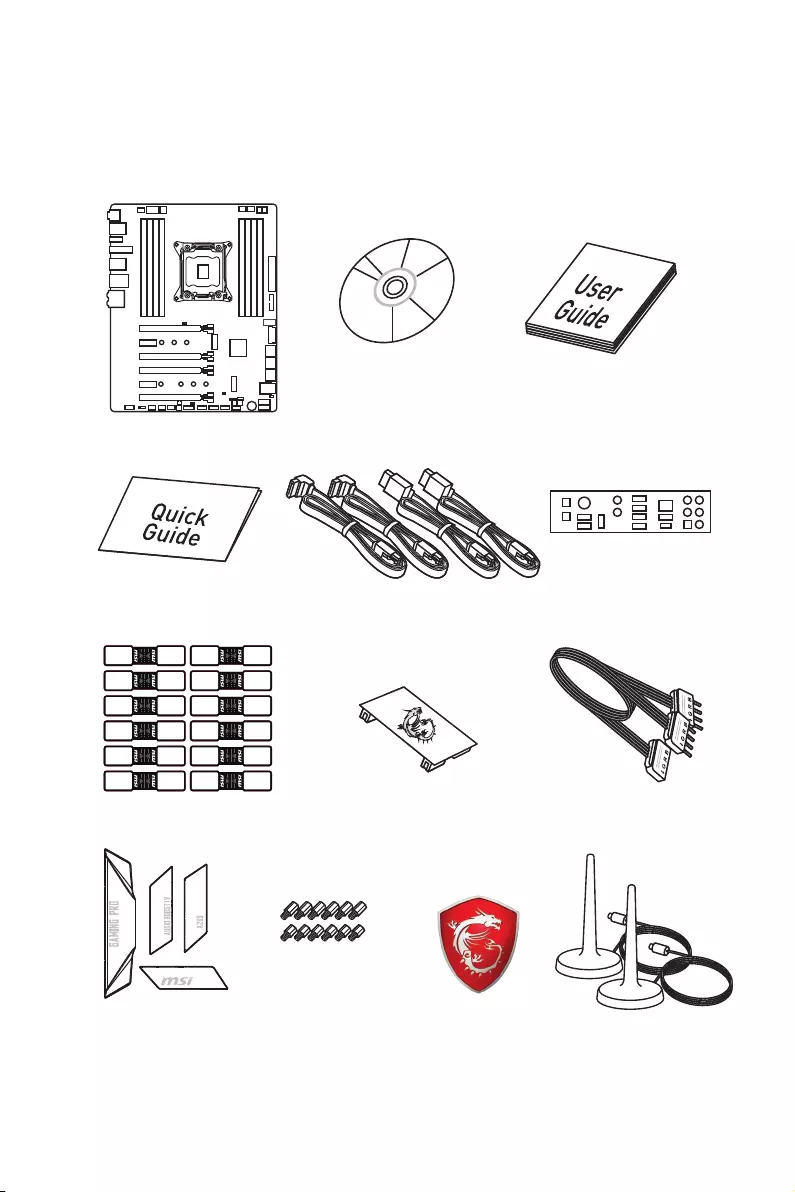
Thank you for buying the MSI® X299 GAMING PRO CARBON/ X299 GAMING PRO
CARBON AC motherboard. Check to make sure your motherboard box contains the
following items. If something is missing, contact your dealer as soon as possible.
Drivers & Utilities
Disc Motherboard User
Guide
Quick Guide
Motherboard
SATA Cable Labels
Case Badge
* MSI® does not guarantee the risks or damages caused by changing the cover.
** These pictures are for reference only and may vary without notice.
SATA Cable x4
1 to 2 RGB LED Extension
Y Cable 80cm x1
Antenna x2
(Optional)
SLI HB Bridge M x1
I/O Shield
3D X-MOUNTING
Screw Pillars
Changeable Cover
Box x1*

2Safety Information
Safety Information
yThe components included in this package are prone to damage from electrostatic
discharge (ESD). Please adhere to the following instructions to ensure successful
computer assembly.
yEnsure that all components are securely connected. Loose connections may cause
the computer to not recognize a component or fail to start.
yHold the motherboard by the edges to avoid touching sensitive components.
yIt is recommended to wear an electrostatic discharge (ESD) wrist strap when
handling the motherboard to prevent electrostatic damage. If an ESD wrist strap is
not available, discharge yourself of static electricity by touching another metal object
before handling the motherboard.
yStore the motherboard in an electrostatic shielding container or on an anti-static pad
whenever the motherboard is not installed.
yBefore turning on the computer, ensure that there are no loose screws or metal
components on the motherboard or anywhere within the computer case.
yDo not boot the computer before installation is completed. This could cause
permanent damage to the components as well as injury to the user.
yIf you need help during any installation step, please consult a certified computer
technician.
yAlways turn off the power supply and unplug the power cord from the power outlet
before installing or removing any computer component.
yKeep this user guide for future reference.
yKeep this motherboard away from humidity.
yMake sure that your electrical outlet provides the same voltage as is indicated on the
PSU, before connecting the PSU to the electrical outlet.
yPlace the power cord such a way that people can not step on it. Do not place anything
over the power cord.
yAll cautions and warnings on the motherboard should be noted.
yIf any of the following situations arises, get the motherboard checked by service
personnel:
Liquid has penetrated into the computer.
The motherboard has been exposed to moisture.
The motherboard does not work well or you can not get it work according to user
guide.
The motherboard has been dropped and damaged.
The motherboard has obvious sign of breakage.
yDo not leave this motherboard in an environment above 60°C (140°F), it may damage
the motherboard.
3
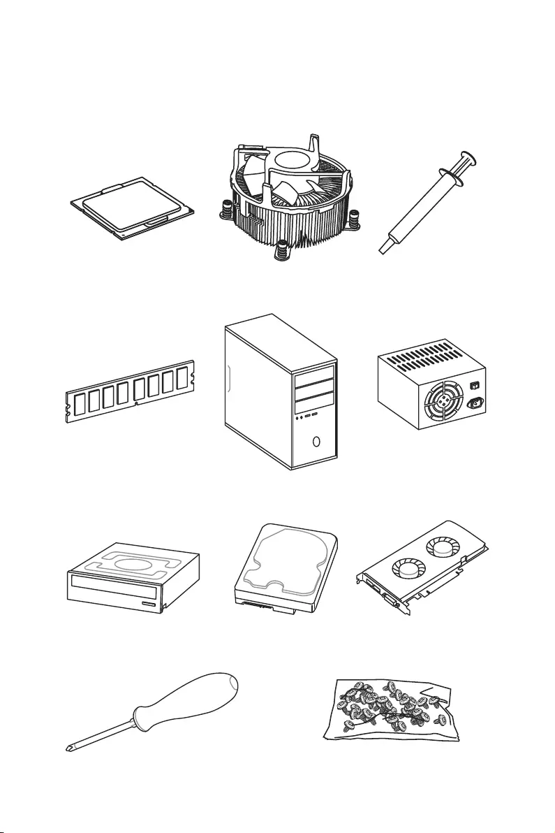
Quick Start
Intel® LGA 2066 CPU
DDR4 Memory
Graphics Card
SATA Hard Disk Drive
SATA DVD Drive
A Package of Screws
Phillips Screwdriver
Chassis
Power Supply Unit
CPU Fan Thermal Paste
Quick Start
Preparing Tools and Components
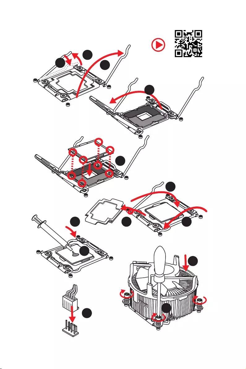
4Quick Start
Installing a Processor
1
2
3
6
4
5
789
10
11
12
13
5
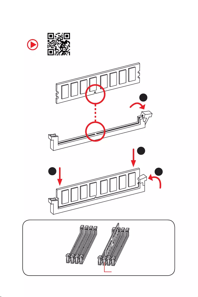
Quick Start
Installing DDR4 memory
1
2
2
3
DIMMC1
6Quick Start
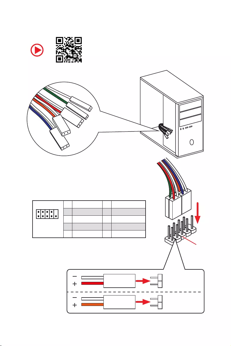
Connecting the Front Panel Header
1
2 10
9
JFP1
1 HDD LED + 2 Power LED +
3 HDD LED — 4 Power LED —
5 Reset Switch 6 Power Switch
7 Reset Switch 8 Power Switch
9 Reserved 10 No Pin
RESET SW
POWER SW
POWER LED+
POWER LED-
HDD LED
HDD LED
RESET SW
JFP1
HDD LED HDD LED —
HDD LED +
POWER LED —
POWER LED +
POWER LED
7
Quick Start
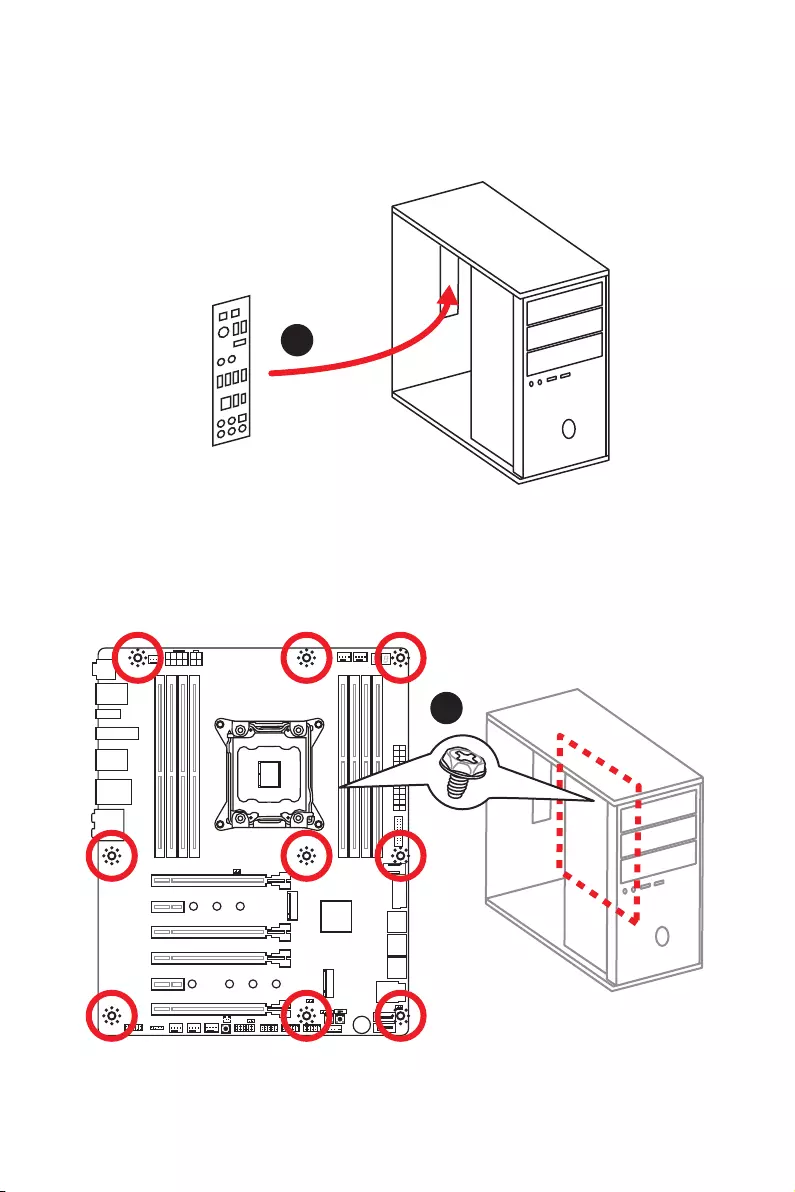
Installing the Motherboard
1
2
8Quick Start
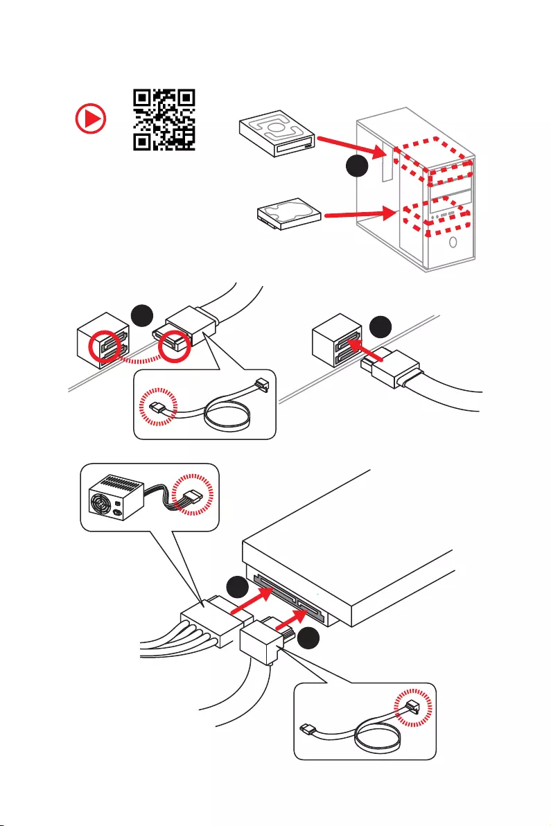
Installing SATA Drives
http://youtu.be/RZsMpqxythc 1
23
4
5
9
Quick Start
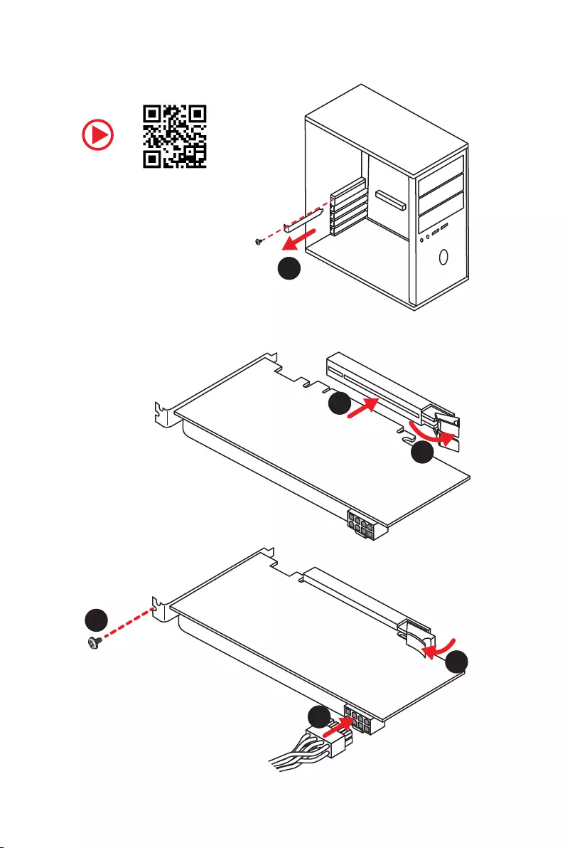
Installing a Graphics Card
1
2
3
4
5
6
10 Quick Start
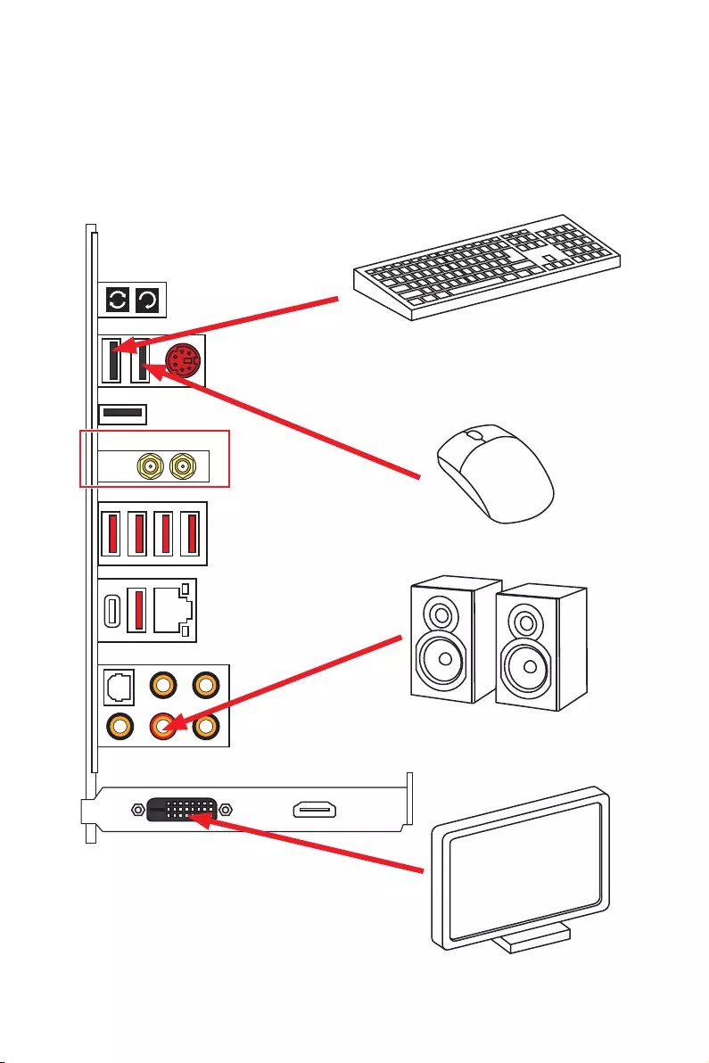
Connecting Peripheral Devices
(Optional)
11
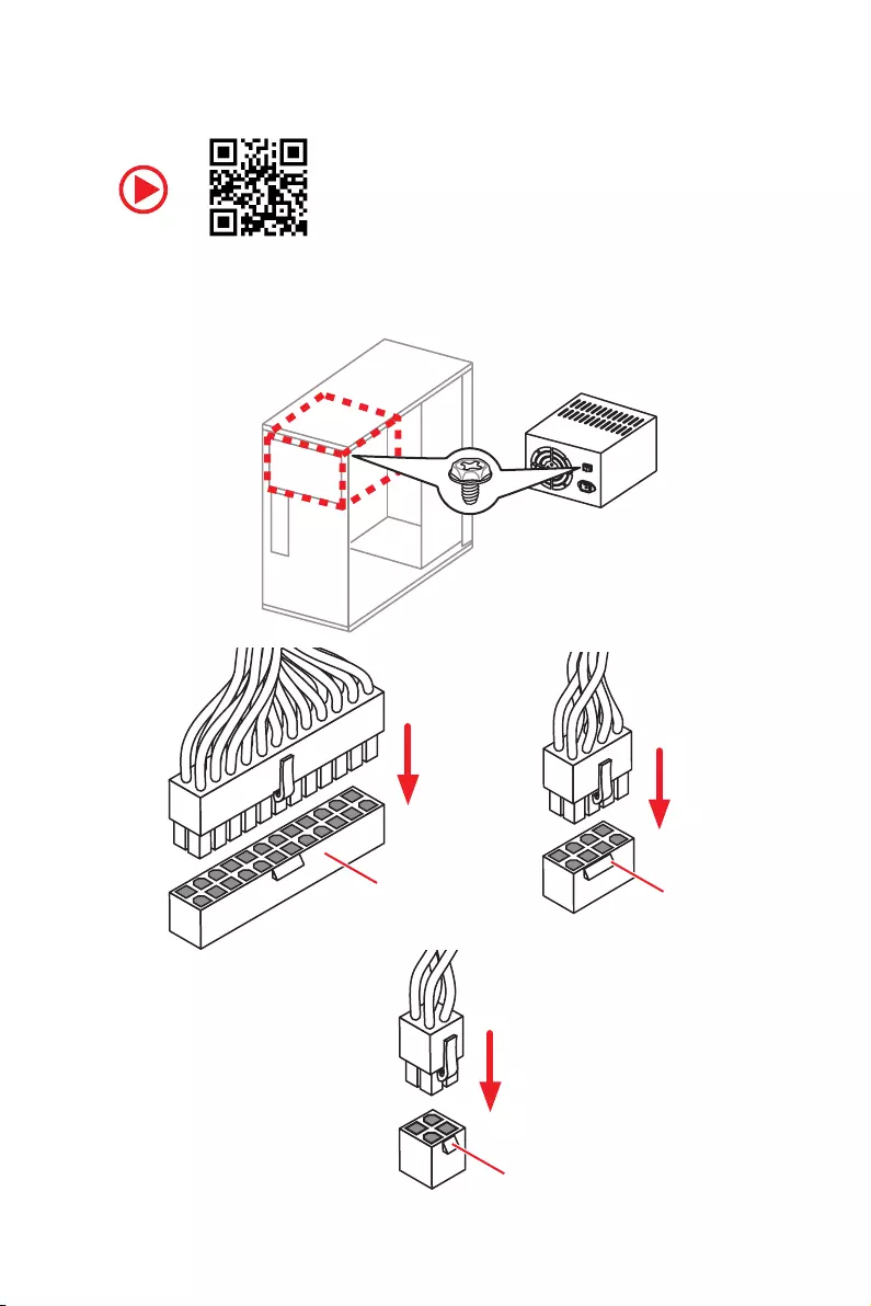
Quick Start
Connecting the Power Connectors
ATX_PWR1 CPU_PWR1
CPU_PWR2
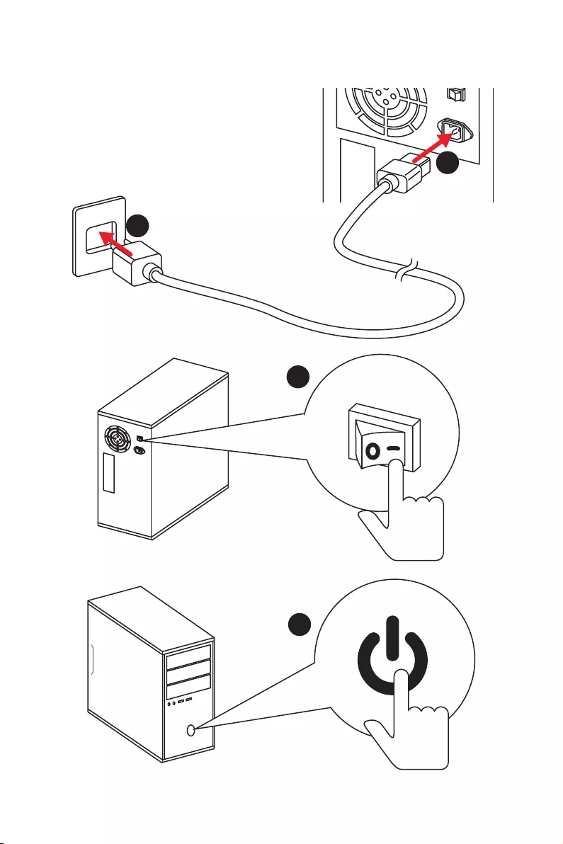
12 Quick Start
Power On
1
4
2
3

13
Contents
Contents
Unpacking ……………………………………………………………………………………………….. 1
Safety Information ……………………………………………………………………………………. 2
Quick Start ………………………………………………………………………………………………. 3
Preparing Tools and Components ……………………………………………………………….. 3
Installing a Processor ………………………………………………………………………………… 4
Installing DDR4 memory ……………………………………………………………………………. 5
Connecting the Front Panel Header …………………………………………………………….. 6
Installing the Motherboard …………………………………………………………………………. 7
Installing SATA Drives………………………………………………………………………………… 8
Installing a Graphics Card ………………………………………………………………………….. 9
Connecting Peripheral Devices …………………………………………………………………. 10
Connecting the Power Connectors …………………………………………………………….. 11
Power On………………………………………………………………………………………………… 12
Specifications …………………………………………………………………………………………. 16
Block Diagram ………………………………………………………………………………………. 22
Rear I/O Panel ……………………………………………………………………………………….. 23
LAN Port LED Status Table……………………………………………………………………….. 23
Audio Ports Configuration ………………………………………………………………………… 23
Realtek HD Audio Manager ………………………………………………………………………. 24
Installing Antennas (Optional) …………………………………………………………………… 26
Overview of Components ………………………………………………………………………… 27
CPU Socket …………………………………………………………………………………………….. 29
DIMM Slots ……………………………………………………………………………………………… 30
PCI_E1~6: PCIe Expansion Slots ……………………………………………………………….. 33
PCIe slots bandwidth table ……………………………………………………………………….. 33
U2_1: U.2 Connector ………………………………………………………………………………… 36
M2_1~2: M.2 Slots (Key M) ……………………………………………………………………….. 37
SATA1~8: SATA 6Gb/s Connectors …………………………………………………………….. 38
OC1: GAME BOOST Knob …………………………………………………………………………. 40
JSLOW1: Slow Mode Booting Jumper ………………………………………………………… 41
CPU_PWR1~2, ATX_PWR1: Power Connectors …………………………………………… 42
JFP1, JFP2: Front Panel Connectors …………………………………………………………. 43
JUSB1, JUSB3: USB 3.1 Gen1 Connectors………………………………………………….. 43
JUSB2: USB 3.1 Gen2 Type-C Connector ……………………………………………………. 44
JUSB4~5: USB 2.0 Connectors ………………………………………………………………….. 45

14 Contents
JTPM1: TPM Module Connector ………………………………………………………………… 45
CPU_FAN1, PUMP_FAN1, SYS_FAN1~4: Fan Connectors …………………………….. 46
JAUD1: Front Audio Connector …………………………………………………………………. 47
JCI1: Chassis Intrusion Connector …………………………………………………………….. 47
BIOS_SW1: Multi-BIOS Switch ………………………………………………………………….. 48
JBAT1: Clear CMOS (Reset BIOS) Jumper ………………………………………………….. 49
POWER1, RESET1: Power Button, Reset Button …………………………………………. 49
JLED1: RGB LED connector ……………………………………………………………………… 50
LED light effect demonstration components ………………………………………………. 50
Onboard LEDs ………………………………………………………………………………………… 51
EZ Debug LEDs ……………………………………………………………………………………….. 51
DIMM LEDs …………………………………………………………………………………………….. 51
XMP LED ………………………………………………………………………………………………… 51
Fan LEDs ………………………………………………………………………………………………… 52
PCIe x16 slot LEDs…………………………………………………………………………………… 52
Debug Code LED ……………………………………………………………………………………… 53
Debug Code LED Table …………………………………………………………………………….. 53
ACPI States Codes …………………………………………………………………………………… 55
CPU Temperature ……………………………………………………………………………………. 55
BIOS Setup …………………………………………………………………………………………….. 56
Entering BIOS Setup ………………………………………………………………………………… 56
Resetting BIOS ………………………………………………………………………………………… 57
Updating BIOS …………………………………………………………………………………………. 57
EZ Mode …………………………………………………………………………………………………. 59
Advanced Mode ………………………………………………………………………………………. 61
SETTINGS ……………………………………………………………………………………………….. 62
Advanced ………………………………………………………………………………………………… 62
Boot ……………………………………………………………………………………………………….. 67
Security ………………………………………………………………………………………………….. 68
Save & Exit ……………………………………………………………………………………………… 69
OC ………………………………………………………………………………………………………….. 70
M-FLASH ……………………………………………………………………………………………….. 76
OC PROFILE ……………………………………………………………………………………………. 77
Software Description ………………………………………………………………………………. 78
Installing Windows® 10 …………………………………………………………………………….. 78
Installing Drivers …………………………………………………………………………………….. 78
Installing Utilities ……………………………………………………………………………………. 78
APP MANAGER ……………………………………………………………………………………….. 79
LIVE UPDATE 6 ………………………………………………………………………………………… 80

15
Contents
COMMAND CENTER ………………………………………………………………………………… 82
GAMING APP …………………………………………………………………………………………… 86
X-BOOST ………………………………………………………………………………………………… 91
MSI SMART TOOL ……………………………………………………………………………………. 93
RAMDISK………………………………………………………………………………………………… 95
GAMING LAN MANAGER ………………………………………………………………………….. 96
DRAGON EYE ………………………………………………………………………………………….. 98
Nahimic 2 ……………………………………………………………………………………………….. 99
XSplit Gamecaster V2 …………………………………………………………………………….. 103
SteelSeries Engine 3 ……………………………………………………………………………… 107
Intel® Extreme Tuning Utility …………………………………………………………………… 109
CPU-Z…………………………………………………………………………………………………… 110
TriDef VR ………………………………………………………………………………………………. 111
TriDef SmartCam …………………………………………………………………………………… 114
RAID Configuration ……………………………………………………………………………….. 115
Using Intel® Rapid Storage Technology Option ROM ………………………………….. 115
Degraded RAID Array …………………………………………………………………………….. 118
M.2 PCIe SSD RAID ………………………………………………………………………………… 120
Intel® Optane™ Memory Configuration …………………………………………………… 123
System Requirements …………………………………………………………………………… 123
Installing the Intel® Optane™ memory …………………………………………………….. 123
Removing the Intel® Optane™ memory ……………………………………………………. 125
Troubleshooting …………………………………………………………………………………….. 126
Troubleshooting …………………………………………………………………………………… 127

16 Specifications
Specifications
CPU ySupports Intel® Core™ X-Series Processor Family for
LGA2066 Socket
Chipset Intel® X299 Chipset
Memory
y8x DDR4 memory slots, support up to 128GB*
X-series processor support DDR4 4266+(OC)/ 4133(OC)/
4000(OC)/ 3866 (OC)/ 3733(OC)/ 3600(OC)/ 3466(OC)/
3400(OC)/ 3333(OC)/ 3300(OC)/ 3200(OC)/ 3000(OC)/
2800(OC)/ 2666/ 2400/ 2133 MHz*
yQuad channel memory architecture with the CPU that
supports up to 4-channels DDR4**
yDual channel memory architecture with the CPU that
supports up to 2-channels DDR4**
ySupports Intel® Extreme Memory Profile (XMP)
* For the latest information about memory, please visit http://www.msi.com
** Please refer the DIMM Slots section for more details.
Expansion Slots
y4x PCIe 3.0 x16 slots
Support x16/ x4/ x16/ x8 mode with the 44 lane CPU.*
Support x16/ x0/ x0/ x0, x16/ x0/ x8/ x0, x16/ x4/ x8/ x0,
x8/ x4/ x8/ x8 modes with the 28 lane CPU.*
Support x8/ x0/ x0/ x0, x8/ x0/ x8/ x0, x8/ x4/ x4/ x0
modes with the 16 lane CPU.*
y2x PCIe 3.0 x1 slots
* Please refer to page 33 for PCIe 3.0 bandwidth table.
Multi-GPU ySupports up to 3-Way AMD® CrossFire™ Technology
ySupports up to 3-Way NVIDIA® SLI™ Technology
LAN 1x Intel I219-V Gigabit LAN controller
Wirsless LAN &
Bluetooth®
(Optional)
yIntel® Dual Band Wireless-AC 8265 module (optional)
The Wireless module is pre-install in the M2_3 (Key-E)
slot.
Supports Wi-Fi 802.11 a/b/g/n/ac, dual band (2.4GHz,
5GHz) up to 867 Mbps speed.
Supports Dual Mode Bluetooth® 2.1, 2.1+EDR, 3.0, 4.0,
BLE, 4.2
Continued on next page

17
Specifications
Continued from previous page
Audio
yRealtek® ALC1220 Codec
y7.1-Channel High Definition Audio
ySupports S/PDIF output
USB
yASMedia® ASM3142 Chipset
1x USB 3.1 Gen2 (SuperSpeed USB 10Gbps) Type-A port
on the back panel
2x USB 3.1 Gen2 (Super Speed USB 10Gbps) Type-C
ports(1 port on the back panel, 1 port available through
the internal USB connector)
yASMedia® ASM1074 Chipset
2x USB 3.1 Gen1 (SuperSpeed USB) Type-A ports on the
back panel
yIntel® X299 Chipset
6x USB 3.1 Gen1 (SuperSpeed USB) ports (2 port on the
back panel, 4 ports available through the internal USB
connectors)
7x USB 2.0 (High-speed USB) ports (3 ports on the
back panel, 4 ports available through the internal USB
connectors)
Storage
Intel® X299 Chipset
y8x SATA 6Gb/s ports*
y2x M.2 slots (Key M)*
Supports up to PCIe 3.0 x4 and SATA 6Gb/s
M2_1 slot supports 2242/ 2260 /2280 storage devices
M2_2 slot supports 2242/ 2260 /2280/ 22110 storage
devices
Intel® Optane™ Memory Ready**
y1x U.2 port *
Supports PCIe 3.0 x4 NVMe storage
ySupports Intel® Smart Response Technology***
* M.2 slots, U.2 port and SATA ports share the same bandwidth. Please refer to
page 38 for U.2, M.2 & SATA combination table.
** Please refer to page 123 for Intel® Optane™ Memory Configuration.
***The functions will be supported depend on the CPU.
Continued on next page

18 Specifications
Continued from previous page
RAID
Intel® X299 Chipset
ySupports RAID 0, RAID 1, RAID 5 and RAID 10 for SATA
storage devices
ySupports RAID 0 and RAID 1 for M.2 storage devices*
* M.2 PCIe RAID volume can be created with M.2/Optane Genie. Please refer to
page 120 for M.2 PCIe SSD RAID.
Internal Connectors
y1x 24-pin ATX main power connector
y1x 8-pin ATX 12V power connector
y1x 4-pin ATX 12V power connector
y8x SATA 6Gb/s connectors
y3x M.2 slots (Key M x2, Key E x1)
y1x U.2 port
y2x USB 2.0 connectors (supports additional 4 USB 2.0
ports)
y2x USB 3.1 Gen1 connectors (supports additional 4 USB 3.1
Gen1 ports)
y1x USB 3.1 Gen2 Type-C port
y1x 4-pin CPU fan connector
y1x 4-pin Water Pump connector
y4x 4-pin system fan connectors
y1x Front panel audio connector
y2x Front panel connectors
y1x TPM module connector
y1x Chassis Intrusion connector
y1x Clear CMOS jumper
y1x Slow mode booting jumper
y1x GAME BOOST knob
y1x Power button
y1x Reset button
y1x Multi-BIOS switch
y1x RGB LED connector
y1x Virtual RAID on CPU connector (VRAID1)
Continued on next page

19
Specifications
Continued from previous page
Back Panel
Connectors
y1x Clear CMOS button
y1x BIOS FLASHBACK+ button
y1x PS/2 keyboard/ mouse combo port
y3x USB 2.0 Type-A ports
y2x Wi-Fi Antenna connectors (optional)
y4x USB 3.1 Gen1 Type-A ports
y1x LAN (RJ45) port
y1x USB 3.1 Gen2 Type-A port
y1x USB 3.1 Gen2 Type-C port
y1x Optical S/PDIF OUT connector
y5x OFC audio jacks
I/O Controller NUVOTON NCT6795 Controller Chip
Hardware Monitor
yCPU/System temperature detection
yCPU/System fan speed detection
yCPU/System fan speed control
Form Factor yATX Form Factor
y12 in. x 9.6 in. (30.5 cm x 24.4 cm)
BIOS Features
y2x 128 Mb flash
yUEFI AMI BIOS
yACPI 6.0, PnP 1.0a, SM BIOS 3.0
yMulti-language
Continued on next page

20 Specifications
Continued from previous page
Software
yDrivers
yAPP MANAGER
ySUPER CHARGER
yCOMMAND CENTER
yLIVE UPDATE 6
yMSI SMART TOOL
yDRAGON EYE
yGAMING APP
yX-BOOST
yMYSTIC LIGHT
yRAMDISK
yGAMING LAN Manager
yFAST BOOT
yNahimic Audio
yXSplit Gamecaster V2
yTridef VR & Smart Cam
ySteelSeries Engine 3
yWTFast*
yCPU-Z MSI GAMING
yIntel® Extreme Tuning Utility
yGoogle Chrome™,Google Toolbar, Google Drive
yNorton™ Internet Security Solution
* This offer is valid for a limited period only, for more information please visit
www.msi.com
MSI Special
Features
yAudio Boost 4
yNahimic 2
yGAMING LAN with Gaming LAN Manager
yIntel WiFi (Optional)
yTurbo U.2
yTwin Turbo M.2
yPump Fan
ySmart Fan Control
Continued on next page

21
Specifications
Continued from previous page
MSI Special
Features
yMystic Light
yMystic Light Extension
yMystic light SYNC
yEZ DEBUG LED
yDDR4 Steel Armor
yM.2 Shield
yPCI-E Steel Armor
yU.2 Steel Armor
yM.2 Steel Armor
yVR Cover
yMuitl GPU — SLI Technology
yMuitl GPU — CrossFire Technology
yDDR4 Boost
yGAME Boost
yOC Engine
yUSB with Type A+C
yLightning USB
yFront Lightning USB
yMilitary Class 5
y7000+ Quality Test
yVR Boost
yVR Ready
yGAMING HOTKEY
yGAMING MOUSE Control
yClick BIOS 5
y BIOS FLASHBACK+
yDual BIOS
yQuadro SLI Ready
yQuadro Ready
yGAMING Certified
ySteelSeries Certified
22 Block Diagram
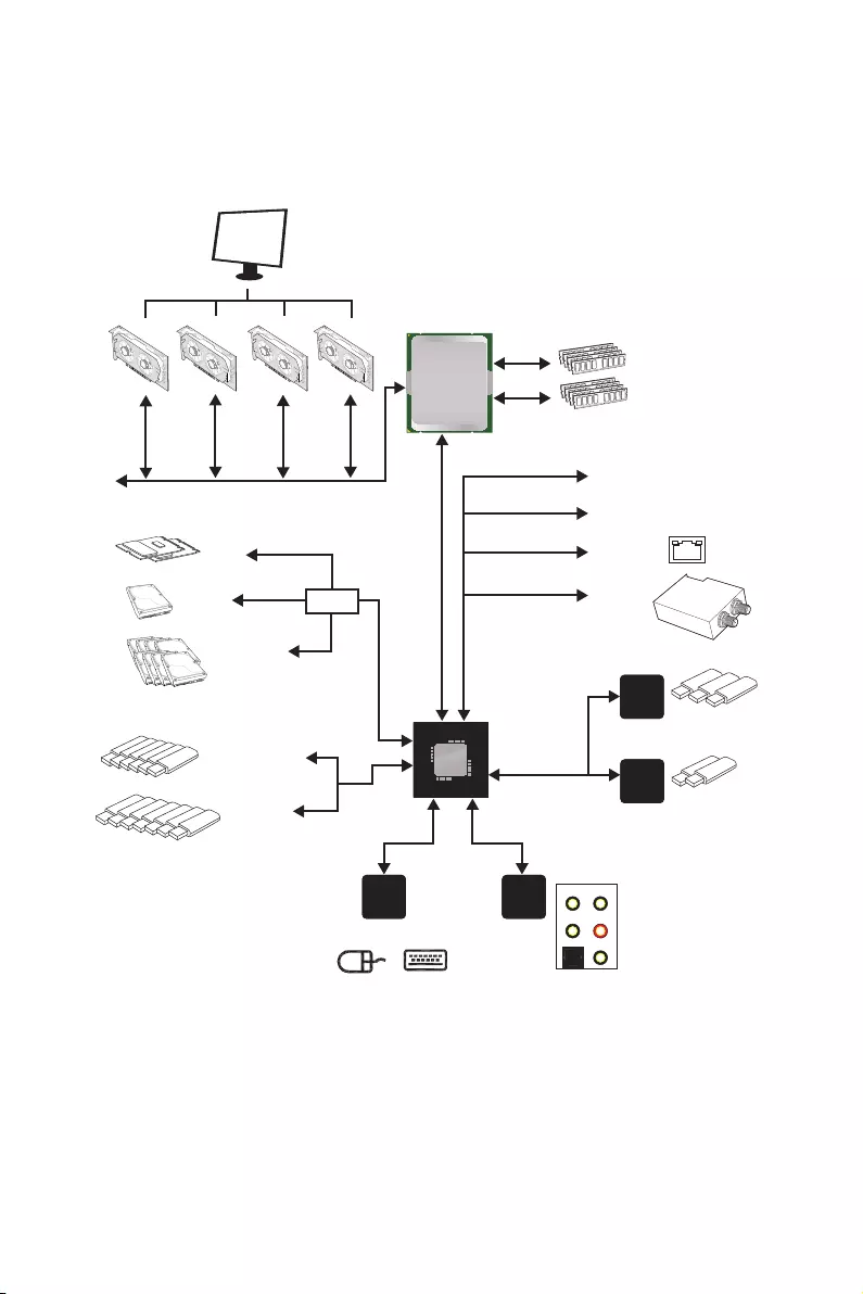
Block Diagram
LPC Bus
2x USB 3.1 Gen1
2/ 4 Channel DDR4 Memory
3x USB 3.1 Gen2
2x M.2
PCIE Bus
PCIE Bus
PCIE Bus
PS/2 Mouse / Keyboard
Wi-Fi /
Bluetooth
DMI 3.0
PCI Express Bus
X299 PCH
Processor
NV6795
Super I/O
Realtek
ALC1220
ASMEDIA
ASM1074
Switch
S/PDIF-Out
Line-In/ SS-Out
Line-OutRS-Out
CS-Out
MIC
8x SATA 6Gb/s
6x USB 3.1 Gen1
7x USB 2.0
1x U.2
PCIe x1 slot
PCIe x1 slot
Intel I219-V
ASMEDIA
ASM3142
23
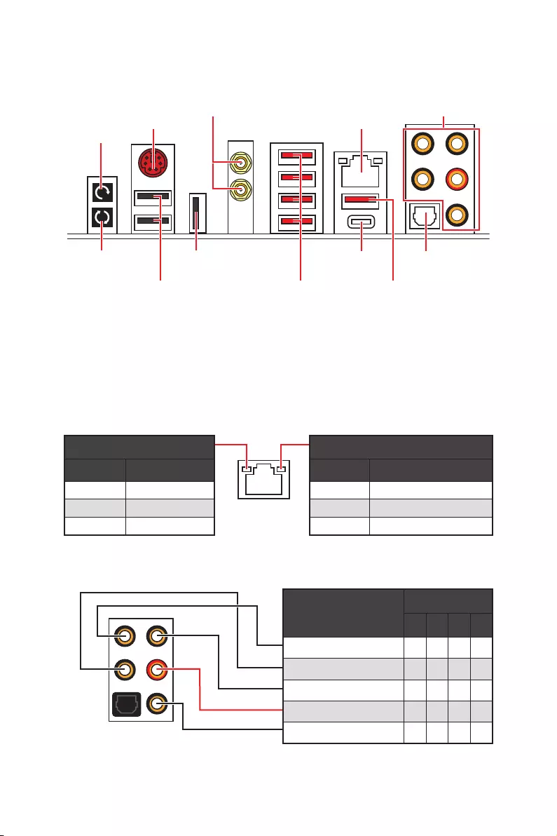
Rear I/O Panel
Rear I/O Panel
yClear CMOS button — Power off your computer. Press and hold the Clear CMOS
button for about 5-10 seconds to reset BIOS to default values.
yBIOS FLASHBACK+ port/ button — Please refer to page 58 for Updating BIOS with
BIOS FLASHBACK+.
PS/2
Wi-Fi Antenna
connectors (Optional)
BIOS FLASHBACK+
button
Audio Ports
Clear CMOS
button
Optical
S/PDIF-Out
USB 2.0/
BIOS FLASHBACK+
USB 3.1 Gen1
Type-A USB 3.1 Gen2
Type-A
USB 3.1 Gen2
Type-C
LAN
USB 2.0
Link/ Activity LED
Status Description
Off No link
Yellow Linked
Blinking Data activity
Speed LED
Status Description
Off 10 Mbps connection
Green 100 Mbps connection
Orange 1 Gbps connection
LAN Port LED Status Table
Audio Ports Configuration
Audio Ports
Channel
2468
Center/ Subwoofer Out ● ●
Rear Speaker Out ●●●
Line-In/ Side Speaker Out ●
Line-Out/ Front Speaker Out ●●●●
Mic In
(●: connected, Blank: empty)
24 Rear I/O Panel
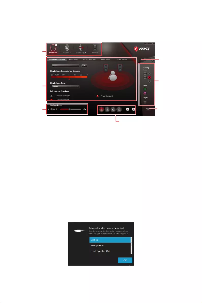
Realtek HD Audio Manager
After installing the Realtek HD Audio driver, the Realtek HD Audio Manager icon will
appear in the system tray. Double click on the icon to launch.
Jack Status
Device
Selection
Connector
Strings
Profiles
Main Volume
Application
Enhancement
Advanced
Settings
yDevice Selection — allows you to select a audio output source to change the related
options. The check sign indicates the devices as default.
yApplication Enhancement — the array of options will provide you a complete guidance
of anticipated sound effect for both output and input device.
yMain Volume — controls the volume or balance the right/left side of the speakers that
you plugged in front or rear panel by adjust the bar.
yProfiles — toggles between profiles.
yAdvanced Settings — provides the mechanism to deal with 2 independent audio
streams.
yJack Status — depicts all render and capture devices currently connected with your
computer.
yConnector Settings — configures the connection settings.
Auto popup dialog
When you plug into a device at an audio jack, a dialogue window will pop up asking you
which device is current connected.
Each jack corresponds to its default setting as shown on the next page.
25
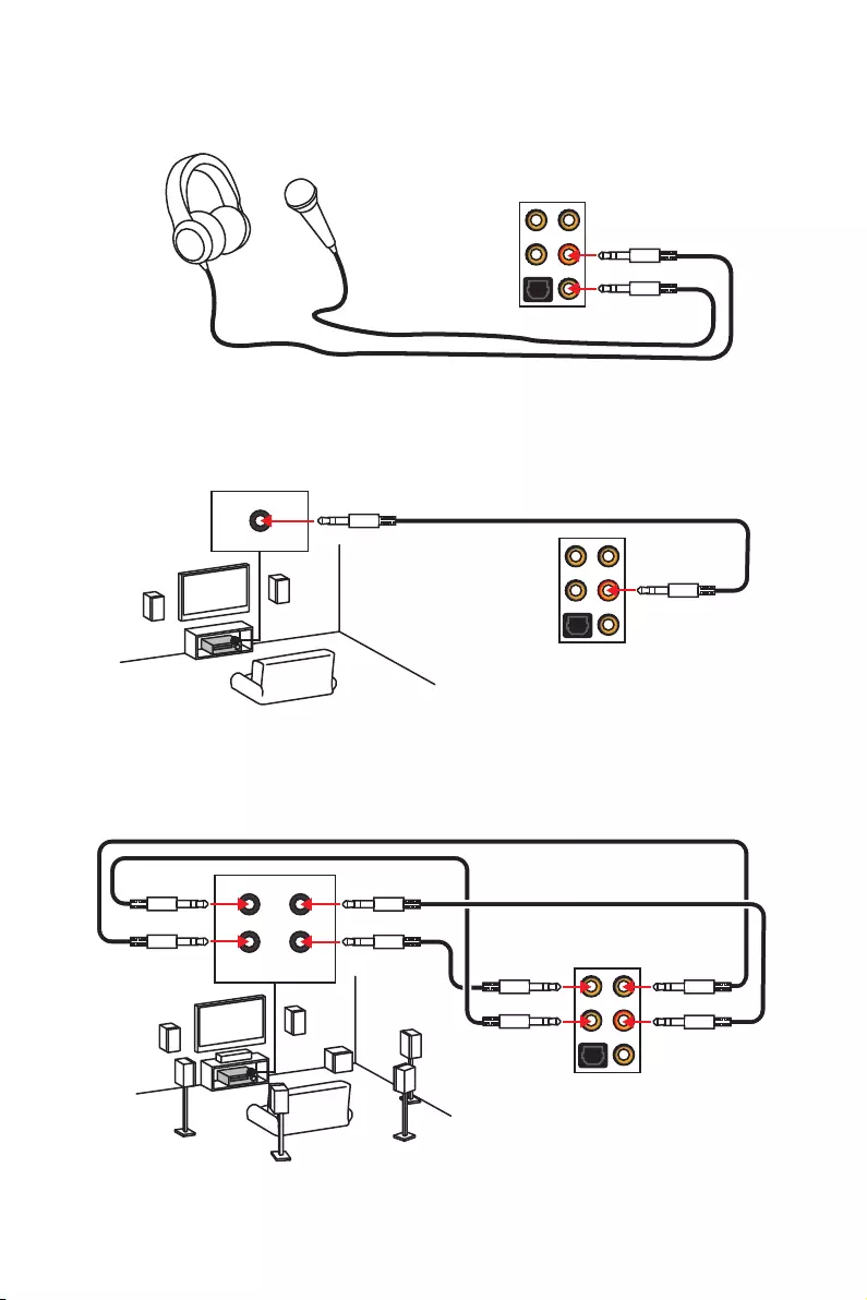
Rear I/O Panel
AUDIO INPUT
Rear Front
Side Center/
Subwoofer
Audio jacks to headphone and microphone diagram
Audio jacks to stereo speakers diagram
Audio jacks to 7.1—channel speakers diagram
AUDIO INPUT
26 Rear I/O Panel
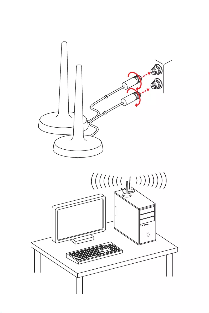
Installing Antennas (Optional)
1. Screw the antennas tight to the Wi-Fi antenna connectors as shown.
2. Place the antennas as high as possible.
27
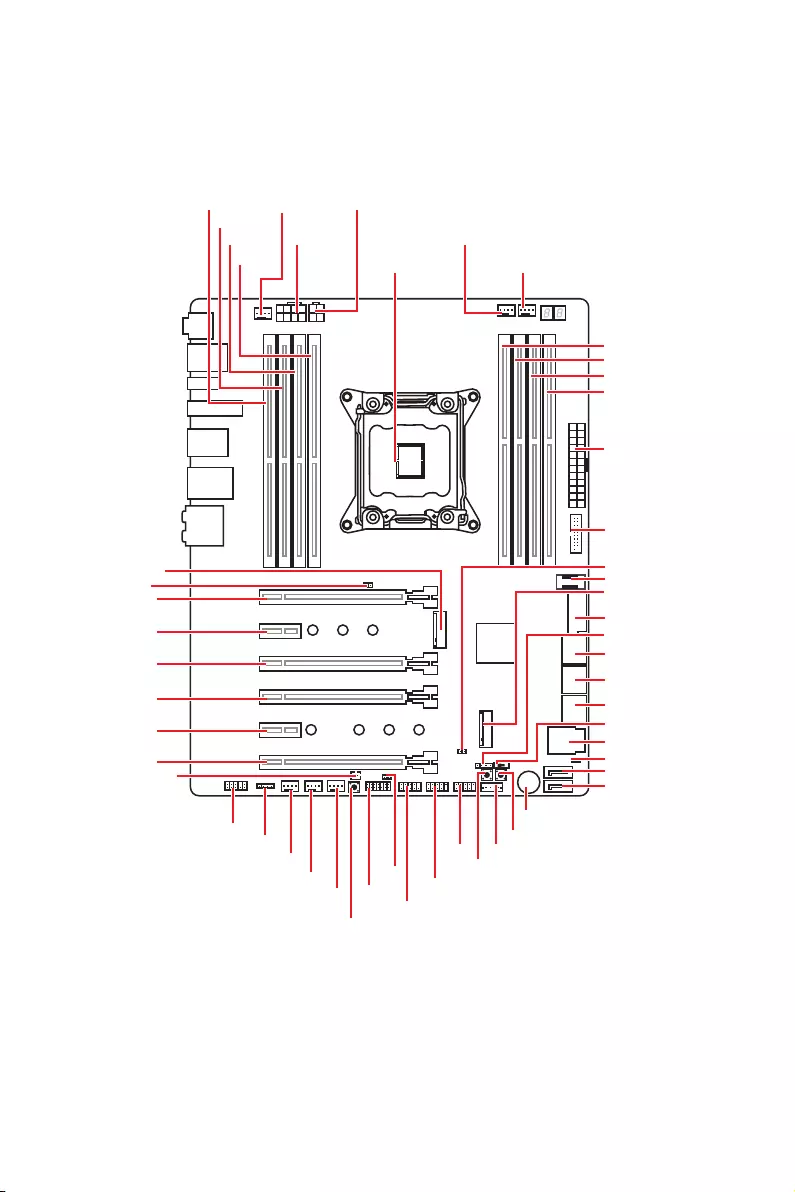
Overview of Components
Overview of Components
PUMP_FAN1
SYS_FAN1
PCI_E1
PCI_E2
JTPM1
PCI_E3
PCI_E4
PCI_E5
PCI_E6
JPWRLED1
CPU Socket
CPU_PWR1
CPU_PWR2
DIMMB2
DIMMB1
M2_1
JBAT1
DIMMC2
CPU_FAN1
DIMMD2
DIMMC1
DIMMD1
OC1
RESET1
POWER1
VRAID1*JUSB4
JUSB5
JFP1
BIOS_SW1
JFP2
SYSFAN4
SYSFAN3
SYSFAN2
JAUD1
JSEL1
JLED1
DEMOLED1
ATX_PWR1
JUSB1
JCI1
JUSB2
U2_1
DIMMA1
DIMMA2
JUSB3
M2_2
SATA7
JSLOW1
SATA8
SATA▼1▲2
SATA▼3▲4
SATA▼5▲6
* VRAID1 is used to connect a specific Intel module/ key.

28 Overview of Components
Component Contents
Port Name Port Type Page
BIOS_SW1 Multi-BIOS Switch 48
CPU_FAN1, PUMP_FAN1, SYS_FAN1~4 Fan Connectors 46
CPU_PWR1~2, ATX_PWR1 Power Connectors 42
CPU Socket LGA 2066 29
DIMMA1~D2 DIMM Slots 30
JAUD1 Front Audio Connector 47
JBAT1 Clear CMOS (Reset BIOS) Jumper 49
JCI1 Chassis Intrusion Connector 47
JFP1, JFP2 Front Panel Connectors 43
JLED1 RGB LED connector 50
JSLOW1 Slow Mode Booting Jumper 41
JTPM1 TPM Module Connector 45
JUSB1, JUSB3 USB 3.1 Gen1 Connectors 43
JUSB2 USB 3.1 Gen2 Type-C Connector 44
JUSB4~5 USB 2.0 Connectors 45
M2_1~2 M.2 Slots (Key M) 37
OC1 GAME BOOST Knob 40
PCI_E1~6 PCIe Expansion Slots 33
POWER1, RESET1 Power Button, Reset Button 49
SATA1~8 SATA 6Gb/s Connectors 38
U2_1 U.2 Connector 36
29
Overview of Components
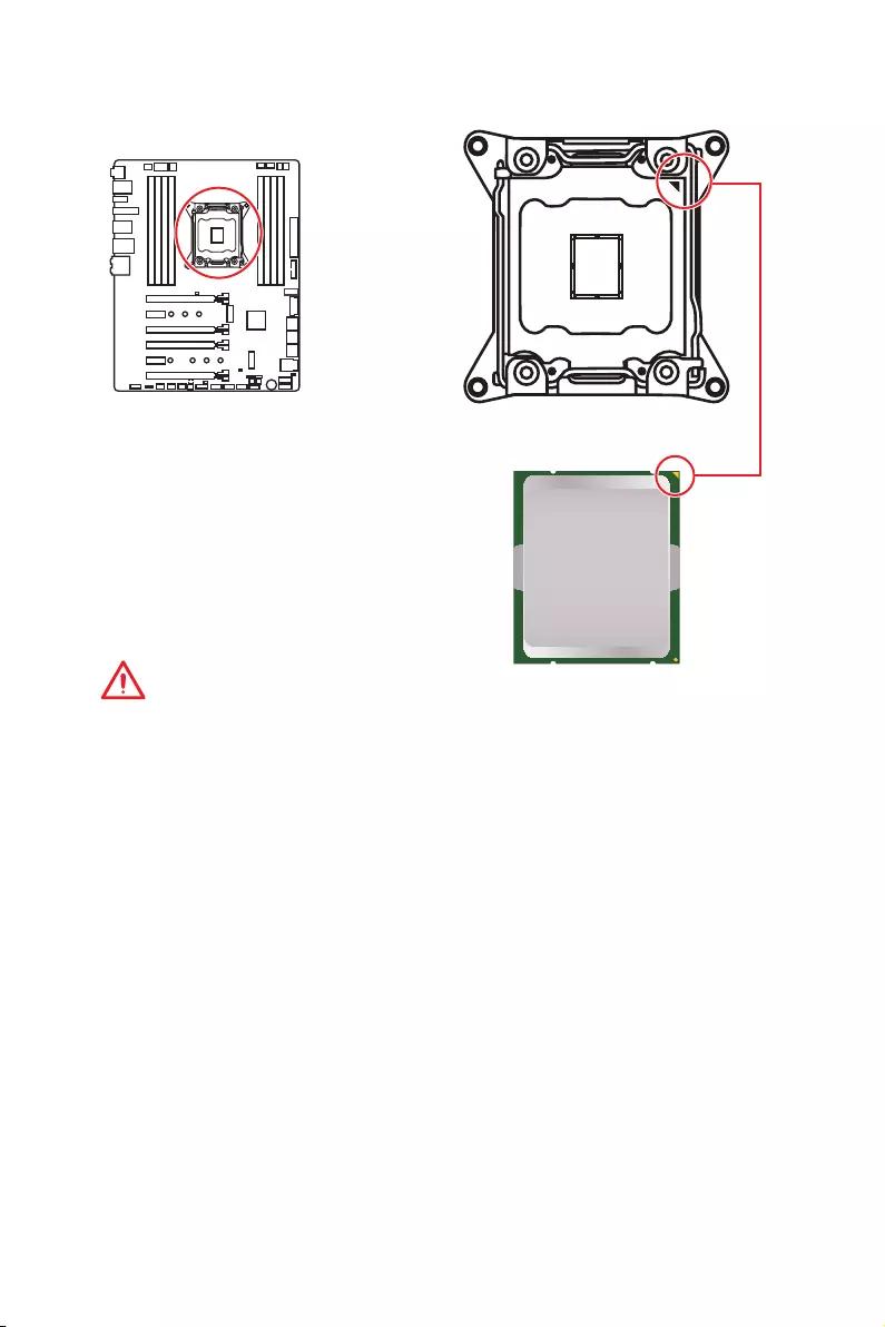
CPU Socket
Introduction to the LGA 2066 CPU
The surface of the LGA2066 CPU has
four alignment keys and a yellow triangle
to assist in correctly lining up the CPU
for motherboard placement. The yellow
triangle is the Pin 1 indicator.
Important
y
Always unplug the power cord from the power outlet before installing or removing
the CPU.
y
Please retain the CPU protective cap after installing the processor. MSI will deal with
Return Merchandise Authorization (RMA) requests if only the motherboard comes with
the protective cap on the CPU socket.
y
When installing a CPU, always remember to install a CPU heatsink. A CPU heatsink
is necessary to prevent overheating and maintain system stability.
y
Confirm that the CPU heatsink has formed a tight seal with the CPU before booting
your system.
y
Overheating can seriously damage the CPU and motherboard. Always make sure
the cooling fans work properly to protect the CPU from overheating. Be sure to apply
an even layer of thermal paste (or thermal tape) between the CPU and the heatsink to
enhance heat dissipation.
y
Whenever the CPU is not installed, always protect the CPU socket pins by covering
the socket with the plastic cap.
y
If you purchased a separate CPU and heatsink/ cooler, Please refer to the
documentation in the heatsink/ cooler package for more details about installation.
y
This motherboard is designed to support overclocking. Before attempting to
overclock, please make sure that all other system components can tolerate
overclocking. Any attempt to operate beyond product specifications is not
recommended. MSI
®
does not guarantee the damages or risks caused by inadequate
operation beyond product specifications.
30 Overview of Components
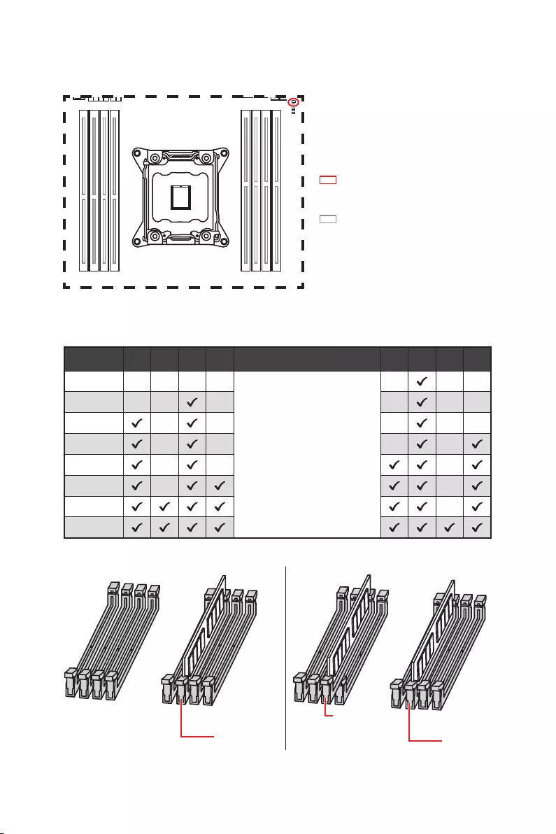
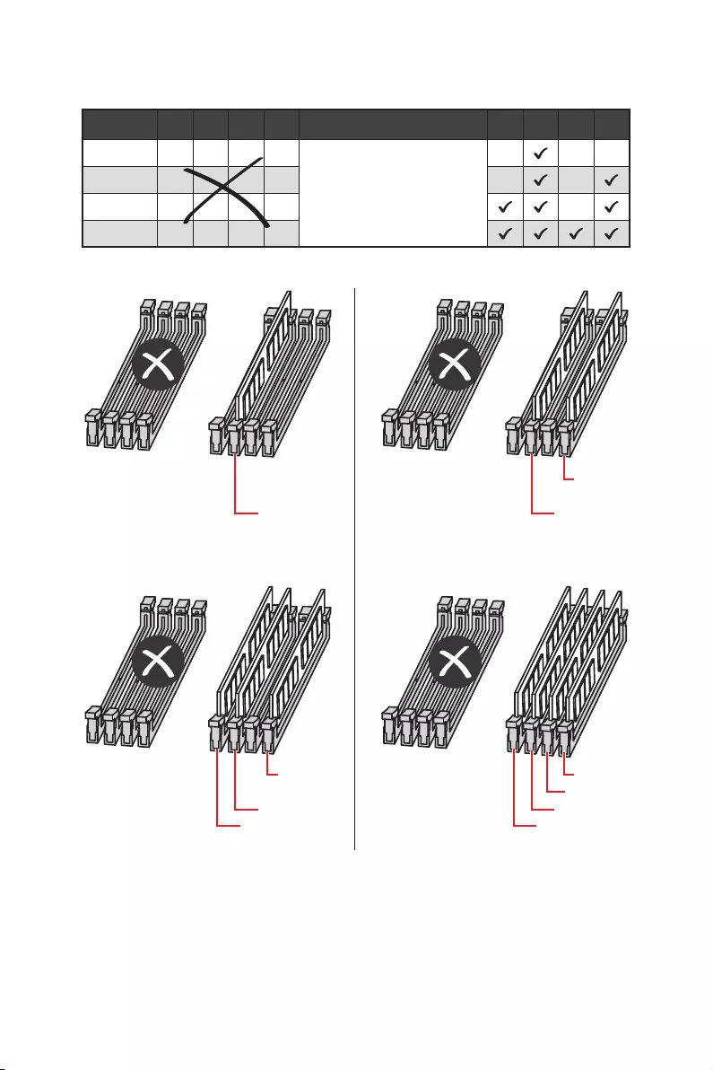
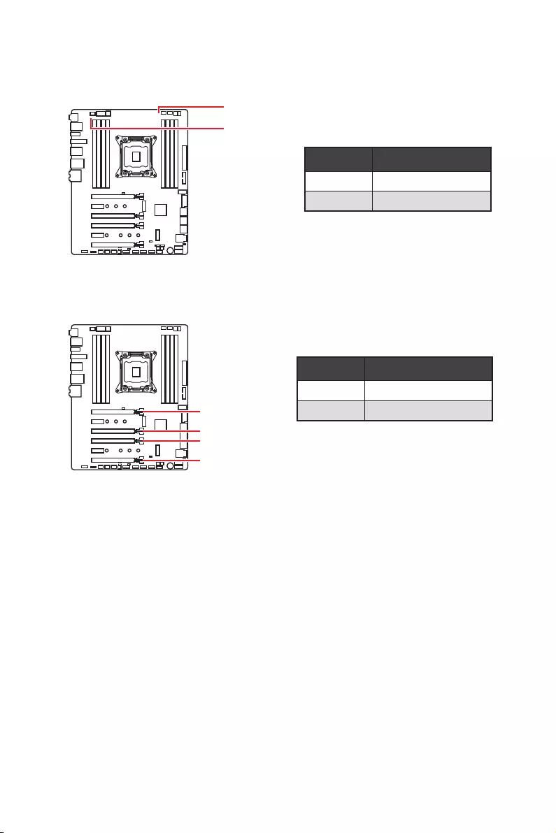
DIMM Slots
DIMMA1
DIMMC1 DIMMC1
B1B2A1A2 C2C1D2D1
Red = 8 DIMMs support
(4-channels architecture CPU)
White = 4 DIMMs support
(2-channels architecture CPU)
S/K LED : S/K LED indicates that
the installed CPU supports either
4-channels or 2-channels memory
architecture.
Memory module installation recommendation (4-Channels architecture CPU )
B1 B2 A1 A2 Intel Core X-series CPU C2 C1 D2 D1
1 DIMM
Supports 4-channels
memory architecture
2 DIMMs
3 DIMMs
4 DIMMs
5 DIMMs
6 DIMMs
7 DIMMs
8 DIMMs
31
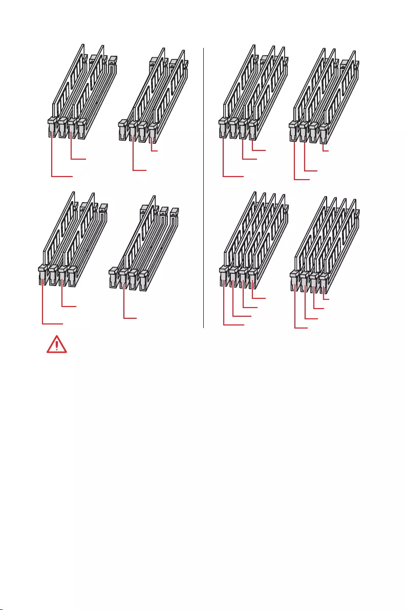
Overview of Components
Important
y
Always insert a memory module in the DIMMC1 slot first.
y
To ensure system stability for Dual/ Triple/ Quad channel mode, memory modules
must be of the same type, number and density. And for every channel, the odd number
DIMM slot must to be installed first.
y
Due to chipset resource usage, the available capacity of memory will be a little less
than the amount of installed.
y
Based on Intel CPU specification, the Memory DIMM voltage below 1.35V is
suggested to protect the CPU.
y
Please note that the maximum capacity of addressable memory is 4GB or less
for 32-bit Windows OS due to the memory address limitation. Therefore, we
recommended that you to install 64-bit Windows OS if you want to install more than
4GB memory on the motherboard.
y
Some memory may operate at a lower frequency than the marked value when
overclocking due to the memory frequency operates dependent on its Serial Presence
Detect (SPD).
y
It is recommended to use a more efficient memory cooling system for full DIMMs
installation or overclocking.
y
The stability and compatibility of installed memory modules depend on installed CPU
and devices when overclocking.
DIMMD1
DIMMC1
DIMMC2
DIMMA1
DIMMB1
DIMMA2
DIMMD1
DIMMC1
DIMMA1
DIMMB1
DIMMB2
DIMMD2
DIMMA2
DIMMC2
DIMMD1
DIMMC1
DIMMA1
DIMMB1
DIMMC1
DIMMA1
DIMMB1
32 Overview of Components
Memory module installation recommendation (2-Channels architecture CPU )
B1 B2 A1 A2 Intel Core X-series CPU C2 C1 D2 D1
1 DIMM
Supports 2-channels
memory architecture
2 DIMMs
3 DIMMs
4 DIMMs
DIMMB1, B2, A1 and A2 are un-available
DIMMD1
DIMMC1 DIMMC1
DIMMD1 DIMMD1
DIMMC1 DIMMC1
DIMMD2
DIMMC2 DIMMC2
33
Overview of Components
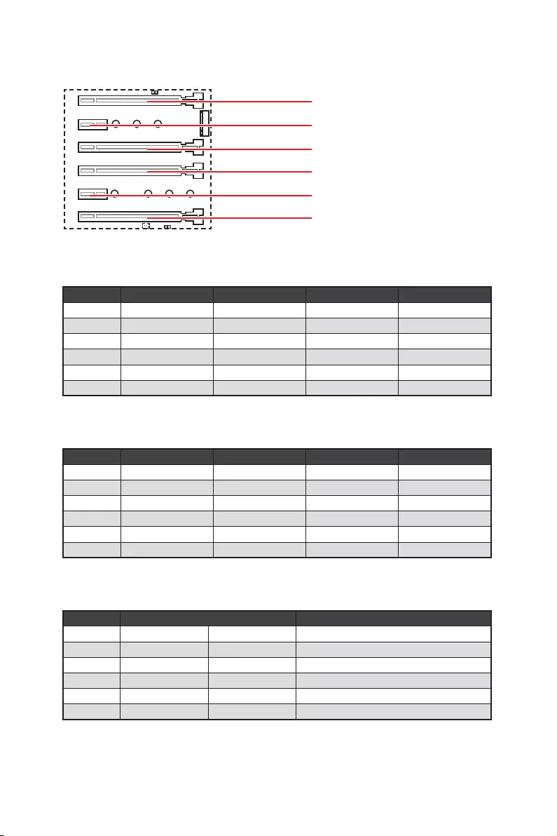
PCI_E1~6: PCIe Expansion Slots
PCI_E1: PCIe 3.0 x16
PCI_E2: PCIe 3.0 x1
PCI_E3: PCIe 3.0 x4
PCI_E4: PCIe 3.0 x16
PCI_E5: PCIe 3.0 x1
PCI_E6: PCIe 3.0 x8
PCIe slots bandwidth table
for 44-lane CPUs
Graphics Card Single 2-Way* 2-Way 3-Way*
PCI_E1 @ 3.0 x16 @ 3.0 x16 @ 3.0 x16 @ 3.0 x16
PCI_E2 3.0 x1 3.0 x1 3.0 x1 3.0 x1
PCI_E3 3.0 x4 3.0 x4 3.0 x4 3.0 x4
PCI_E4 3.0 x16 @ 3.0 x16 3.0 x16 @ 3.0 x16
PCI_E5 3.0 x1 3.0 x1 3.0 x1 3.0 x1
PCI_E6 3.0 x8 3.0 x8 @ 3.0 x8 @ 3.0 x8
(@: graphics card slot, *: best combination)
for 28-lane CPU
Graphics Card Single 2-Way* 2-Way 3-Way
PCI_E1 @ 3.0 x16 @ 3.0 x16 @ 3.0 x8 @ 3.0 x8
PCI_E2 3.0 x1 3.0 x1 3.0 x1 3.0 x1
PCI_E3 3.0 x4 3.0 x4 3.0 x4 3.0 x4
PCI_E4 3.0 x8 @ 3.0 x8 3.0 x8 @ 3.0 x8
PCI_E5 3.0 x1 3.0 x1 3.0 x1 3.0 x1
PCI_E6 Empty Empty @ 3.0 x8 @ 3.0 x8
(@: graphics card slot, *: best combination)
for 16-lane CPU
Graphics Card Single 2-Way*
PCI_E1 @ 3.0 x8 @ 3.0 x8 @ 3.0 x8
PCI_E2 3.0 x1 3.0 x1 3.0 x1
PCI_E3 Empty 3.0 x4 Empty
PCI_E4 3.0 x8 3.0 x4 @ 3.0 x8
PCI_E5 3.0 x1 3..0 x1 3.0 x1
PCI_E6 ─ ─ ─
(@: graphics card slot, ─: unavailable, *: best combination)
34 Overview of Components
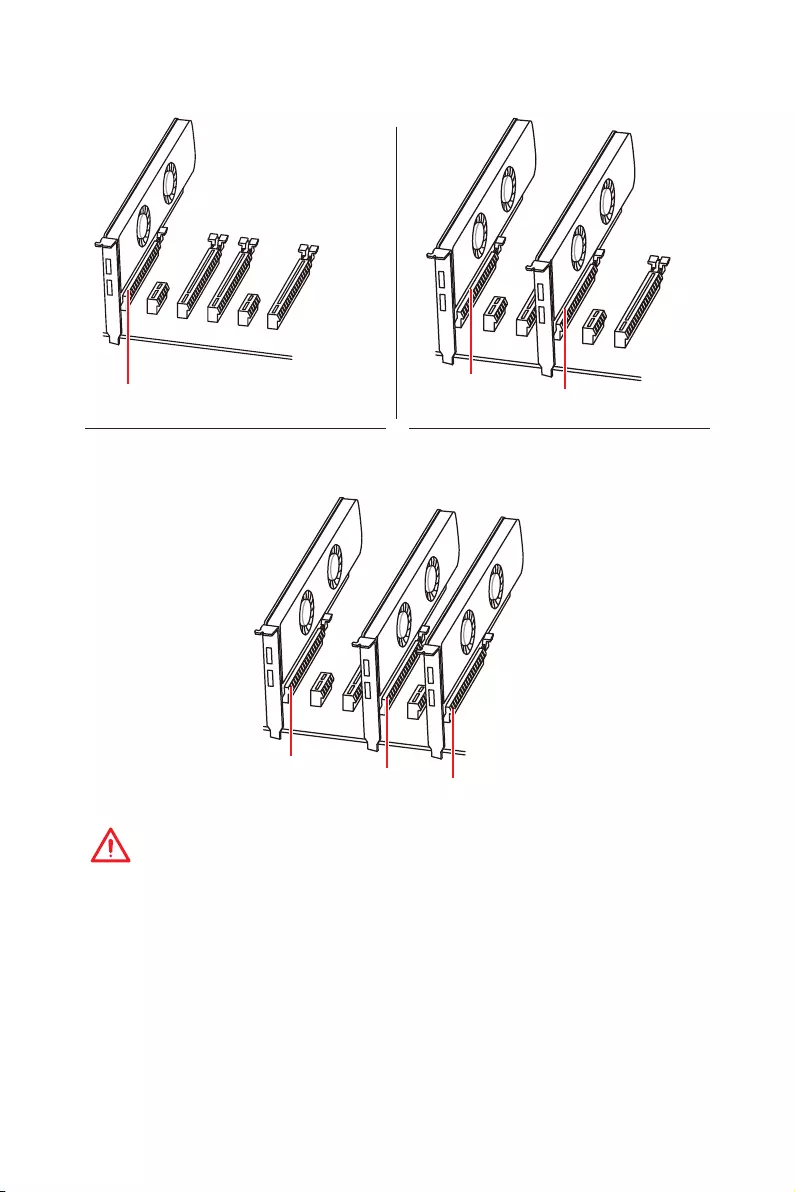
PCI_E1 PCI_E1
PCI_E1
PCI_E4
PCI_E6
PCI_E4
Multiple graphics cards installation recommendation
For 44- & 28-lane CPU
Important
y
If you install a large and heavy graphics card, you need to use a tool such as MSI
Gaming Series Graphics Card Bolster to support its weight and to prevent deformation
of the slot.
y
For a single PCIe x16 expansion card installation with optimum performance, using
the PCI_E1 slot is recommended.
35
Overview of Components
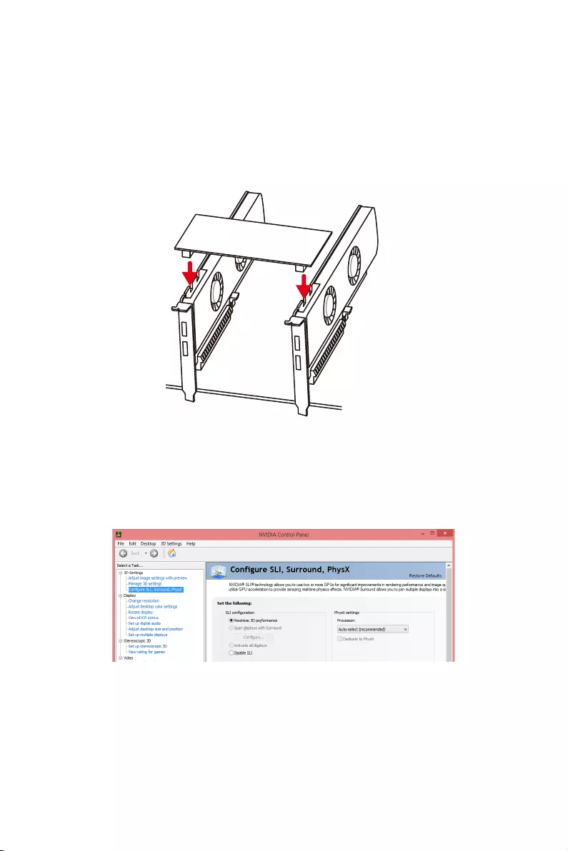
Installing SLI graphics cards
For power supply recommendations for SLI configurations, please refer to the user
guide of your graphics card to make sure you meet all the system requirements.
To install SLI graphics cards:
1. Turn off your computer and disconnect the power cord, install two graphics cards
into the PCI_E1 and PCI_E4 slots.
2. Connect the two cards together using the SLI Bridge Connector.
3. Connect all PCIe power connectors of the graphics cards.
4. Reconnect the power cord, power up the computer and install the drivers and
software included in your graphics card package.
5. Right-click the Windows desktop and select NVIDIA Control Panel from the menu,
click on Configure SLI, Surround, PhysX in the left task pane and select Maximize
3D performance in the SLI configuration menu, and then click Apply.
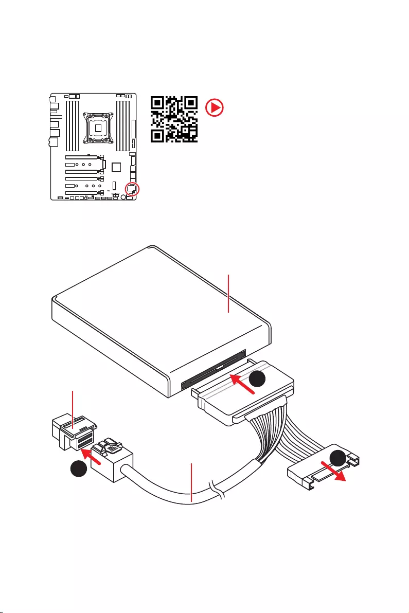
36 Overview of Components
Video Demonstration
Watch the video to learn how to Install
U.2 SSD.
U2_1: U.2 Connector
This connector is a U.2 interface port. Each connector can connect to one PCIe 3.0 x4
NVMe storage device.
Installing U.2 SSD
1. Connect the U.2 cable to the U.2 connector on the
motherboard.
2. Connect the U.2 cable to the U.2 SSD.
3. Connect the U.2 cable to power adapter cable.
1
2
3
U.2 SSD
U.2 Connector
U.2 Cable
Connect to power
adapter cable
37
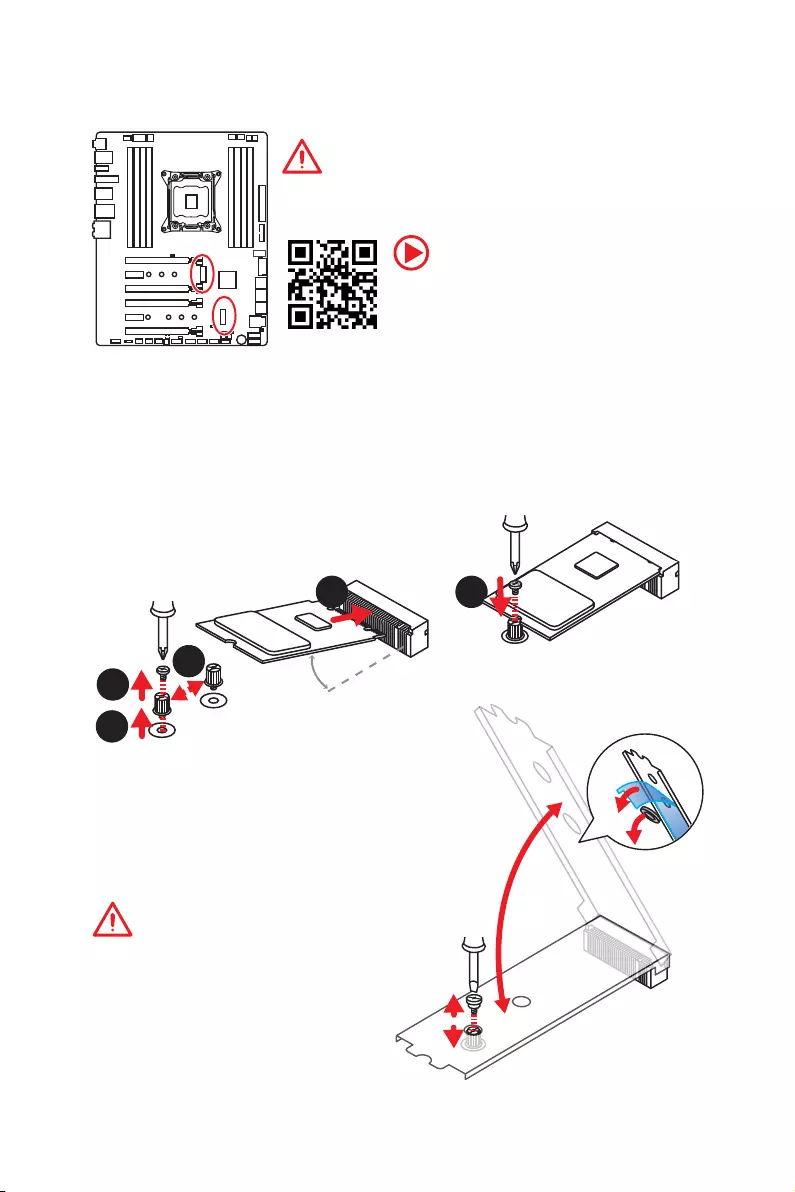
Overview of Components
Important
y
Intel
®
RST only supports PCIe M.2 SSD with UEFI ROM.
y
Intel
®
Optane™ Memory Ready for all M.2 slots.
M2_1~2: M.2 Slots (Key M)
1
2
330°
5
Installing M.2 module
1. Remove the screw from the base screw.
2. Remove the base screw.
3. Tighten the base screw into the hole of
the distance to the M.2 slot as the length
your M.2 module.
4. Insert your M.2 module into the M.2 slot
at a 30-degree angle.
5. Put the screw in the notch on
the trailing edge of your M.2
module and tighten it into the
base screw.
4
Video Demonstration
Watch the video to learn how to Install M.2
module.
http://youtu.be/JCTFABytrYA
Using M.2 shield
We provide the M.2 shield on the M.2 slot to help dissipate
heat away from the M.2 module. Before installing the M.2
module for the first time, you need to remove the screw,
lift the cover and remove the protective film and the
round rubber from the thermal pad.
Important
If you don’t need the M.2 shield, you can
remove it.
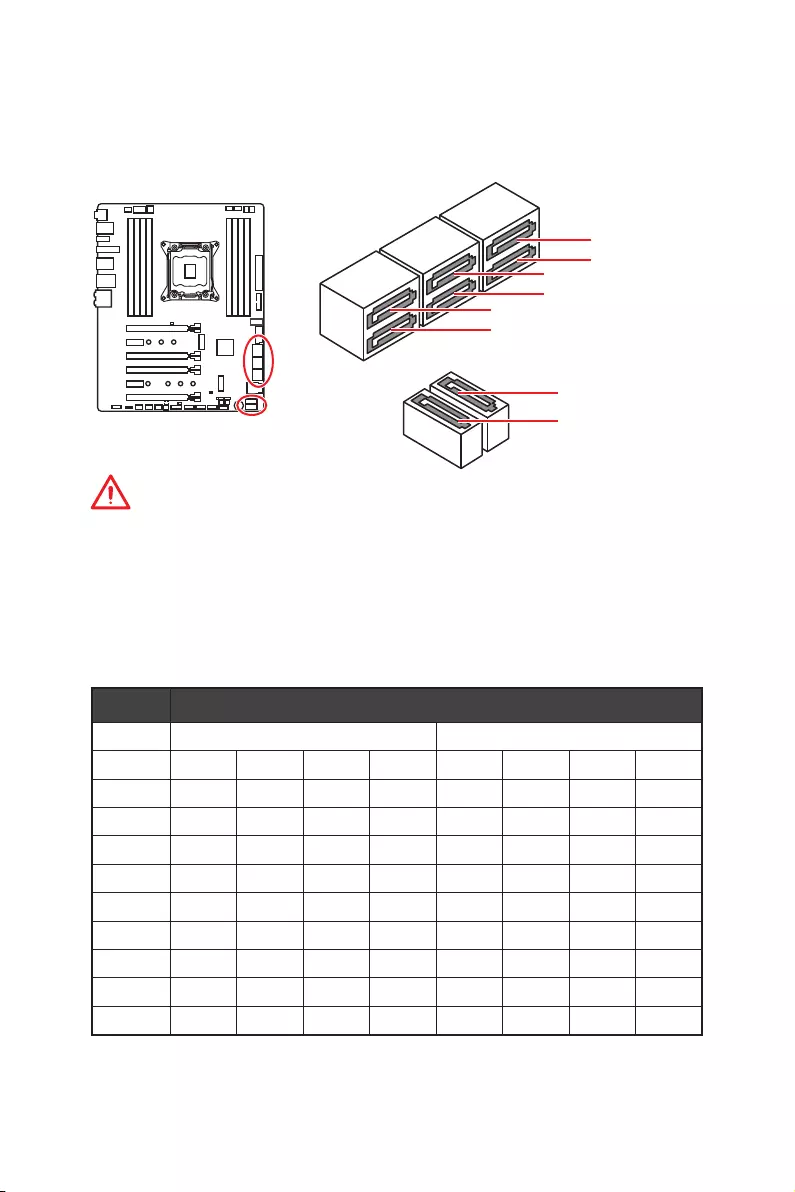
38 Overview of Components
SATA1~8: SATA 6Gb/s Connectors
These connectors are SATA 6Gb/s interface ports. Each connector can connect to one
SATA device.
Important
y
Please do not fold the SATA cable at a 90-degree angle. Data loss may result during
transmission otherwise.
y
SATA cables have identical plugs on either sides of the cable. However, it is
recommended that the flat connector be connected to the motherboard for space
saving purposes.
SATA2
SATA3
SATA5
SATA4
SATA6
SATA1
SATA8
SATA7
U.2, M.2 & SATA combination table
Slot Available SATA connectors
U2_1 ✓Empty
M2_1 PCIe SATA SATA PCIe PCIe SATA SATA PCIe
M2_2 PCIe SATA PCIe SATA PCIe SATA PCIe SATA
SATA1 ✓ ─ ─ ✓ ✓ ─ ─ ✓
SATA2 ✓─✓─✓─✓─
SATA3 ✓✓✓✓✓✓✓✓
SATA4 ✓✓✓✓✓✓✓✓
SATA5 ─ ─ ─ ─ ✓ ✓ ✓ ✓
SATA6 ─ ─ ─ ─ ✓ ✓ ✓ ✓
SATA7 ─ ─ ─ ─ ✓ ✓ ✓ ✓
SATA8 ─ ─ ─ ─ ✓ ✓ ✓ ✓
(SATA: M.2 SATA SSD, PCIe: M.2 PCIe SSD, ✓: available, ─: unavailable)
39
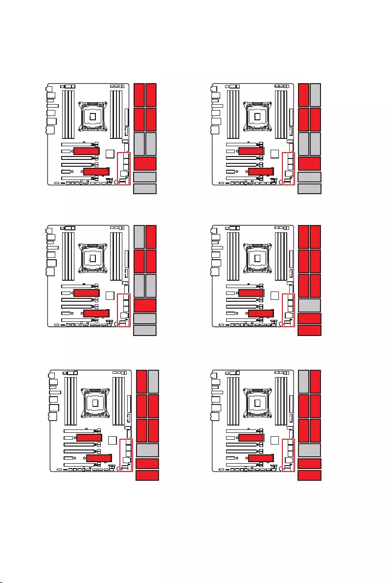
Overview of Components
1xU.2+ 2xM.2 PCIe+ 4xSATA
M.2 slots with examples of various combination possibilities
M.2 PCIe
M.2 PCIe
SATA4 SATA2U.2
SATA1SATA3
M.2 SATA
M.2 PCIe
SATA4 SATA2U.2
SATA3
1xU.2+ 1xM.2 SATA+ 1xM.2 PCIe+
3xSATA
1xU.2+ 1xM.2 PCIe+ 1xM.2 SATA+
3xSATA
M.2 PCIe
M.2 SATA
SATA4U.2
SATA1SATA3
2xM.2 PCIe+ 8xSATA
M.2 PCIe
M.2 PCIe
SATA4SATA6 SATA2
SATA1SATA3SATA5
SATA7
SATA8
1xM.2 SATA+ 1xM.2 PCIe+ 7xSATA
M.2 SATA
M.2 PCIe
SATA4SATA6 SATA2
SATA3SATA5
SATA7
SATA8
1xM.2 PCIe+ 1xM.2 SATA+ 7xSATA
M.2 PCIe
M.2 SATA
SATA4SATA6
SATA1SATA3SATA5
SATA7
SATA8
40 Overview of Components
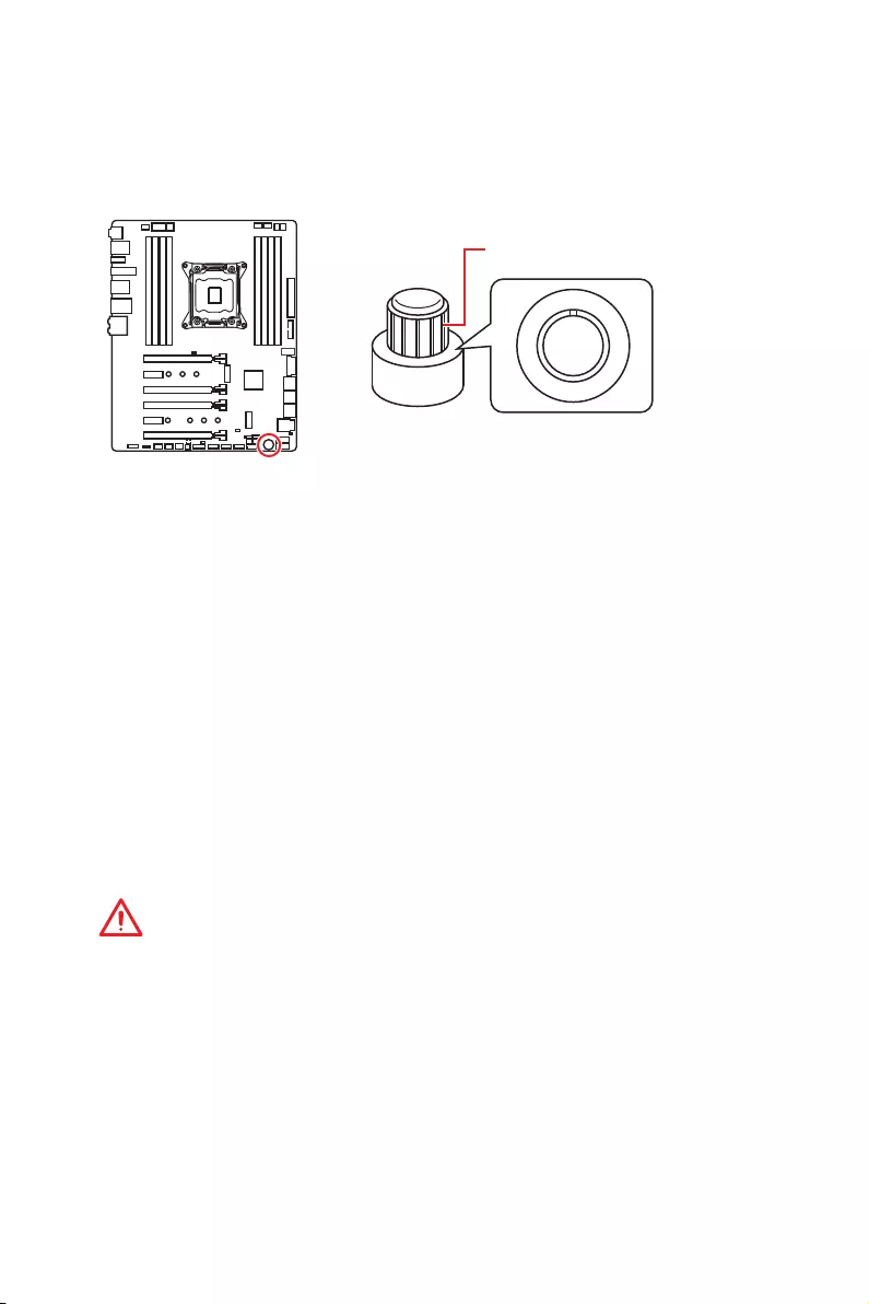
OC1: GAME BOOST Knob
This knob allows you to manually select a stage from number 0 (default) to number 11
(extreme) for overclocking the processor. The processor’s voltage and frequency will
be automatically adjusted after you power on your computer.
0
1
2
4
6
8
1
0
1
1
GAME BOOST knob
Using GAME BOOST Knob
To setup the GAME BOOST knob, take the following steps:
1. Set the GAME BOOST knob to hardware mode in BIOS Setup.
Note: The light of this knob will be turned on to indicate that the GAME BOOST is
controller by hardware. When the light is off, it indicates that the GAME BOOST is
controller by BIOS.
2. Power off the computer.
3. Rotate the GAME BOOST knob to select the overclocking stage as you desire.
4. Power on and then GAME BOOST will automatically overclock processor depending
on the stage you selected.
To disable GAME BOOST:
1. Set the GAME BOOST knob to HW mode in BIOS Setup.
2. Power off the computer.
3. Rotate the GAME BOOST knob to 0 and then power on. The configuration
parameters will be returned to default values.
Important
y
You can also control the GAME BOOST function in BIOS Setup or with MSI COMMAND
CENTER software.
y
In order to optimize performance and improve system stability, when you activate the
GAME BOOST function, please leave the settings in the BIOS > OC menu unchanged.
y
The success of overclocking depends on the components of your computer.
y
We do not guarantee the GAME BOOST overclocking range or the damages/ risks
caused by overclocking behavior.
y
MSI components are recommended for better compatibility when using GAME
BOOST function.
41
Overview of Components
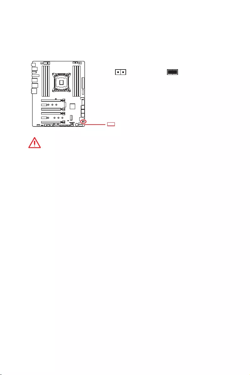
JSLOW1: Slow Mode Booting Jumper
This jumper is used for LN2 cooling solution, that provides the extreme overclocking
conditions, to boot at a stable processor frequency and to prevent the system from
crashing.
Normal
(default)
Enabled
(Please enable this
jumper during BIOS
POST.)
Important
y
Users will try extreme low temperature overclocking at their own risks. The
overclocking results will vary according to the CPU version.
y
Please don’t switch to Enabled when power-off or the system will be un-bootable.
Red LED indicates that the
Slow Mode is enabled.
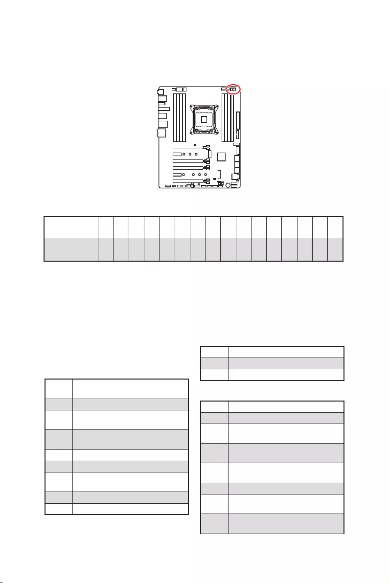
42 Overview of Components
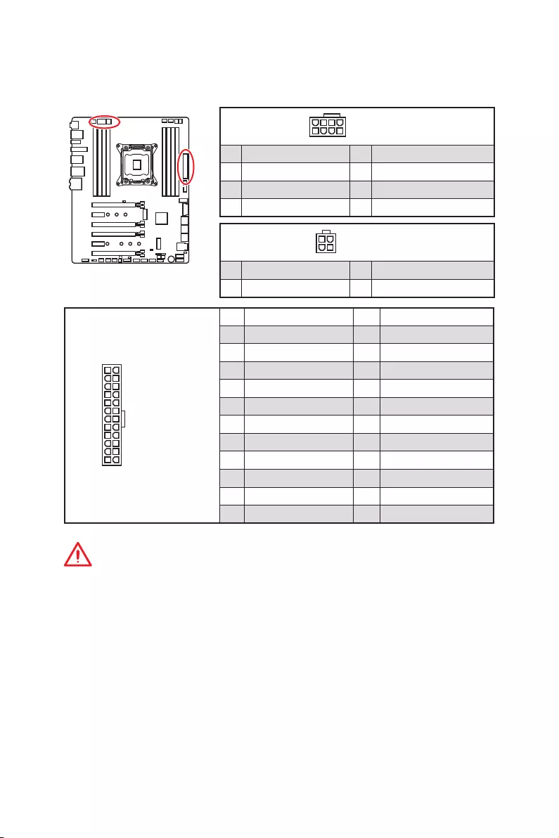
24
131
12
ATX_PWR1
1 +3.3V 13 +3.3V
2 +3.3V 14 -12V
3 Ground 15 Ground
4 +5V 16 PS-ON#
5 Ground 17 Ground
6 +5V 18 Ground
7 Ground 19 Ground
8 PWR OK 20 Res
9 5VSB 21 +5V
10 +12V 22 +5V
11 +12V 23 +5V
12 +3.3V 24 Ground
5
4 1
8CPU)_PWR1
1 Ground 5 +12V
2 Ground 6 +12V
3 Ground 7 +12V
4 Ground 8 +12V
Important
Make sure that all the power cables are securely connected to a proper ATX power
supply to ensure stable operation of the motherboard.
CPU_PWR1~2, ATX_PWR1: Power Connectors
These connectors allow you to connect an ATX power supply.
3
2 1
4CPU_PWR2
1 Ground 3 +12V
2 Ground 4 +12V
43
Overview of Components
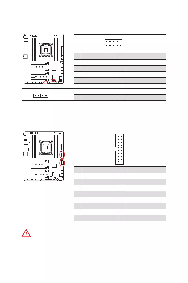
JFP1, JFP2: Front Panel Connectors
These connectors connect to the switches and LEDs on the front panel.
1
2 10
9
JFP1
1 HDD LED + 2 Power LED +
3 HDD LED — 4 Power LED —
5 Reset Switch 6 Power Switch
7 Reset Switch 8 Power Switch
9 Reserved 10 No Pin
1
JFP2
1 Speaker — 2 Buzzer +
3 Buzzer — 4 Speaker +
JUSB1, JUSB3: USB 3.1 Gen1 Connectors
These connectors allow you to connect USB 3.1 Gen1 ports on the front panel.
1
10 11
20
1Power 11 USB2.0+
2 USB3_RX_DN 12 USB2.0-
3 USB3_RX_DP 13 Ground
4 Ground 14 USB3_TX_C_DP
5 USB3_TX_C_DN 15 USB3_TX_C_DN
6 USB3_TX_C_DP 16 Ground
7 Ground 17 USB3_RX_DP
8 USB2.0- 18 USB3_RX_DN
9 USB2.0+ 19 Power
10 Ground 20 No Pin
Important
Note that the Power and Ground pins must be connected correctly to avoid possible
damage.
44 Overview of Components
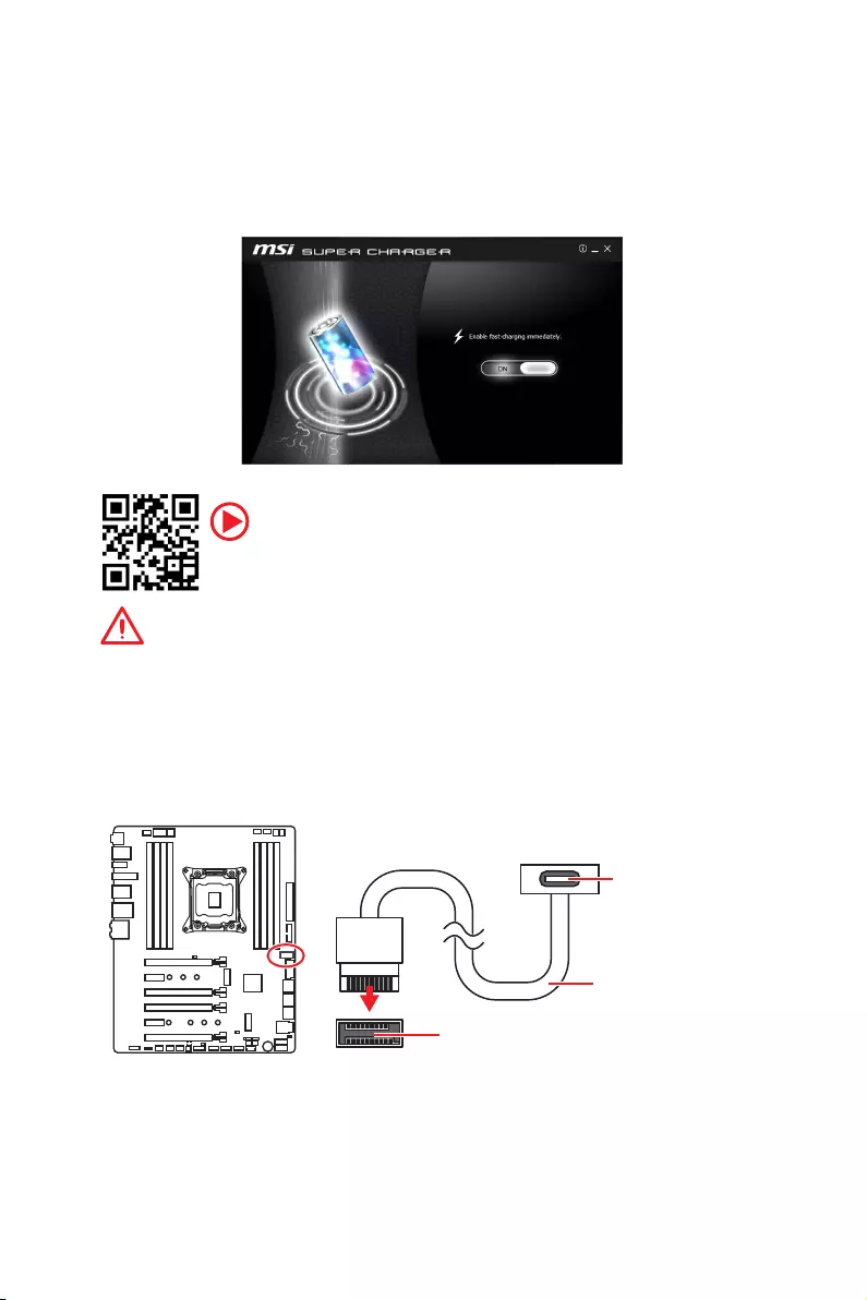
JUSB2: USB 3.1 Gen2 Type-C Connector
This connector allows you to connect USB 3.1 Gen2 Type-C connector on the front
panel. The connector possesses a foolproof design. When you connect the cable, be
sure to connect it with the corresponding orientation.
JUSB2
USB Type-C Cable
USB Type-C port on
the front panel
Charger Port
The JUSB1 connector is a charger port which can increase USB power output for fast
charging your smartphone or USB-powered devices. The Charger Port is hardware
controlled by motherboard chip, it can still charge your device in suspend, hibernate
state or even shutdown states. However, when you boot the computer into Windows®,
you will need to install the MSI® SUPER CHARGER application to turn ON/OFF the
Charging mode.
Video Demonstration
Watch the video to learn how to charge the smartphone with Super-
Charger. http://youtu.be/FCyvjr5NbOw
Important
When the Charging mode is enabled, the Charger Port data syncing will be disabled.
45
Overview of Components
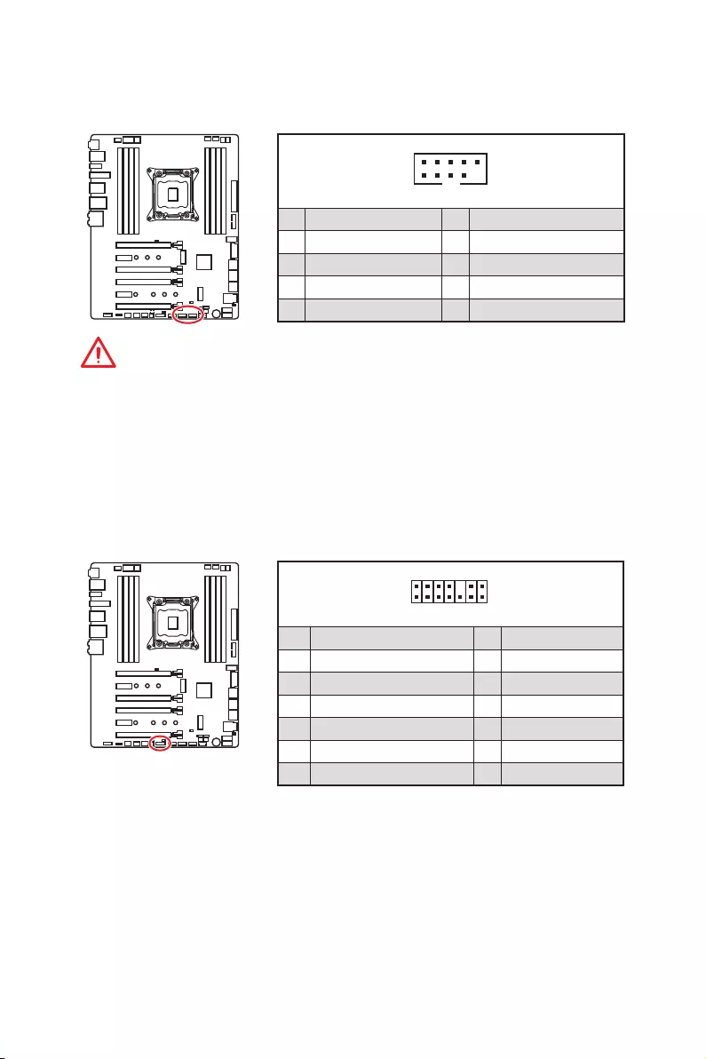
JUSB4~5: USB 2.0 Connectors
These connectors allow you to connect USB 2.0 ports on the front panel.
1
2 10
9
1VCC 2VCC
3 USB0- 4 USB1-
5 USB0+ 6 USB1+
7 Ground 8 Ground
9 No Pin 10 NC
Important
y
Note that the VCC and Ground pins must be connected correctly to avoid possible
damage.
y
In order to recharge your iPad,iPhone and iPod through USB ports, please install
MSI
®
SUPER CHARGER utility.
1
2 14
13
1 LPC Clock 2 3V Standby power
3 LPC Reset 4 3.3V Power
5 LPC address & data pin0 6 Serial IRQ
7 LPC address & data pin1 8 5V Power
9 LPC address & data pin2 10 No Pin
11 LPC address & data pin3 12 Ground
13 LPC Frame 14 Ground
JTPM1: TPM Module Connector
This connector is for TPM (Trusted Platform Module). Please refer to the TPM security
platform manual for more details and usages.
46 Overview of Components
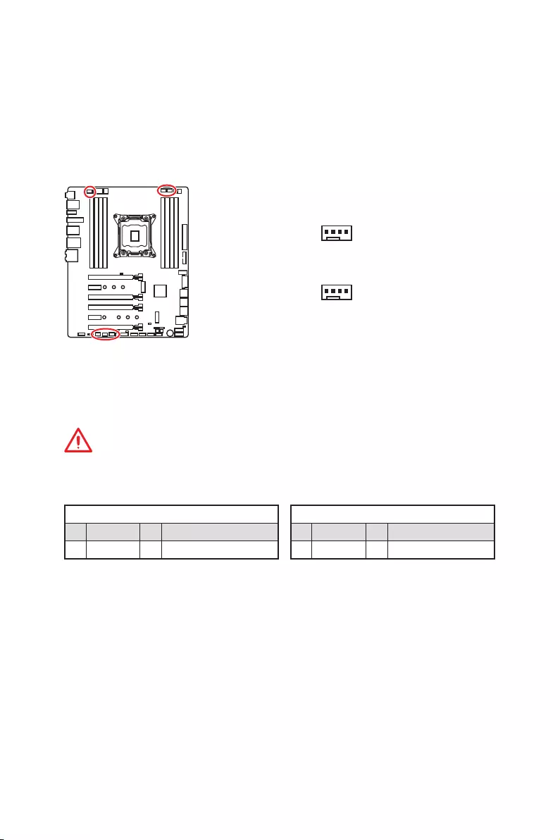
CPU_FAN1, PUMP_FAN1, SYS_FAN1~4: Fan Connectors
Fan connectors can be classified as PWM (Pulse Width Modulation) Mode or DC Mode.
PWM Mode fan connectors provide constant 12V output and adjust fan speed with
speed control signal. DC Mode fan connectors control fan speed by changing voltage.
When you plug a 3-pin (Non-PWM) fan to a fan connector in PWM mode, the fan speed
will always maintain at 100%, which might create a lot of noise. You can follow the
instruction below to adjust the fan connector to PWM or DC Mode.
PWM Mode pin definition
1 Ground 2 +12V
3 Sense 4 Speed Control Signal
DC Mode pin definition
1 Ground 2 Voltage Control
3 Sense 4 NC
Switching fan mode and adjusting fan speed
You can switch between PWM mode and DC mode and adjust fan speed in BIOS >
HARDWARE MONITOR.
Important
Make sure fans are working properly after switching the PWM/ DC mode.
Pin definition of fan connectors
1
1
CPU_FAN1/ PUMP _FAN1
SYS_FAN1~4
Auto-detection Mode fan connectors
47
Overview of Components
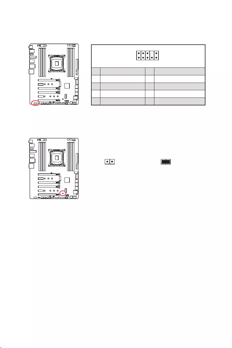
JAUD1: Front Audio Connector
This connector allows you to connect audio jacks on the front panel.
1
2 10
9
1 MIC L 2 Ground
3 MIC R 4 NC
5 Head Phone R 6 MIC Detection
7 SENSE_SEND 8 No Pin
9 Head Phone L 10 Head Phone Detection
JCI1: Chassis Intrusion Connector
This connector allows you to connect the chassis intrusion switch cable.
Normal
(default)
Trigger the chassis
intrusion event
Using chassis intrusion detector
1. Connect the JCI1 connector to the chassis intrusion switch/ sensor on the chassis.
2. Close the chassis cover.
3. Go to BIOS > SETTINGS > Security > Chassis Intrusion Configuration.
4. Set Chassis Intrusion to Enabled.
5. Press F10 to save and exit and then press the Enter key to select Yes.
6. Once the chassis cover is opened again, a warning message will be displayed on
screen when the computer is turned on.
Resetting the chassis intrusion warning
1. Go to BIOS > SETTINGS > Security > Chassis Intrusion Configuration.
2. Set Chassis Intrusion to Reset.
3. Press F10 to save and exit and then press the Enter key to select Yes.
48 Overview of Components
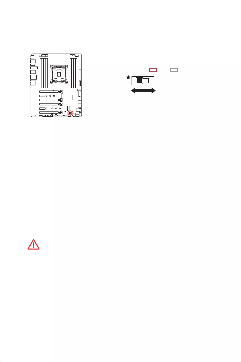
BIOS_SW1: Multi-BIOS Switch
This motherboard has two built-in BIOS ROMs (Labeled A and B, default BIOS ROM is
A). If one is crashed, you can shift to the other for booting by sliding the switch.
Recovering BIOS
When BIOS updating fails or causes the computer non-bootable, you can recover the
failed BIOS by the steps below. Before recovering, please download the latest BIOS file
that matches your motherboard model from MSI website. And then save the BIOS file
to the root of the USB flash drive.
1. Power off the computer.
2. Switch to the normal BIOS ROM with BIOS1 switch.
3. Insert the USB flash drive into the computer.
4. Power on the computer and press Del key to enter BIOS setup during POST.
5. Select the M-FLASH tab and click on Yes to reboot the system and enter the flash
mode.
6. Select a BIOS file to perform the BIOS recovering process.
7. Switch to the failed BIOS ROM with Multi-BIOS switch, and click on Yes to start
recovering BIOS.
8. After the recovering process is completed, the system will reboot automatically.
Important
y
Do not use the Multi-BIOS switch when system is booting up.
y
You can also use the LIVE UPDATE or BIOS FLASHBACK+ utility to flash BIOS. Please
refer to BIOS section for details.
BIOS BBIOS A
(default)
BIOS A LED BIOS B LED
49
Overview of Components
POWER1, RESET1: Power Button, Reset Button
The Power / Reset button allows you to power on / reset the computer.
Keep Data
(default)
Clear CMOS/
Reset BIOS
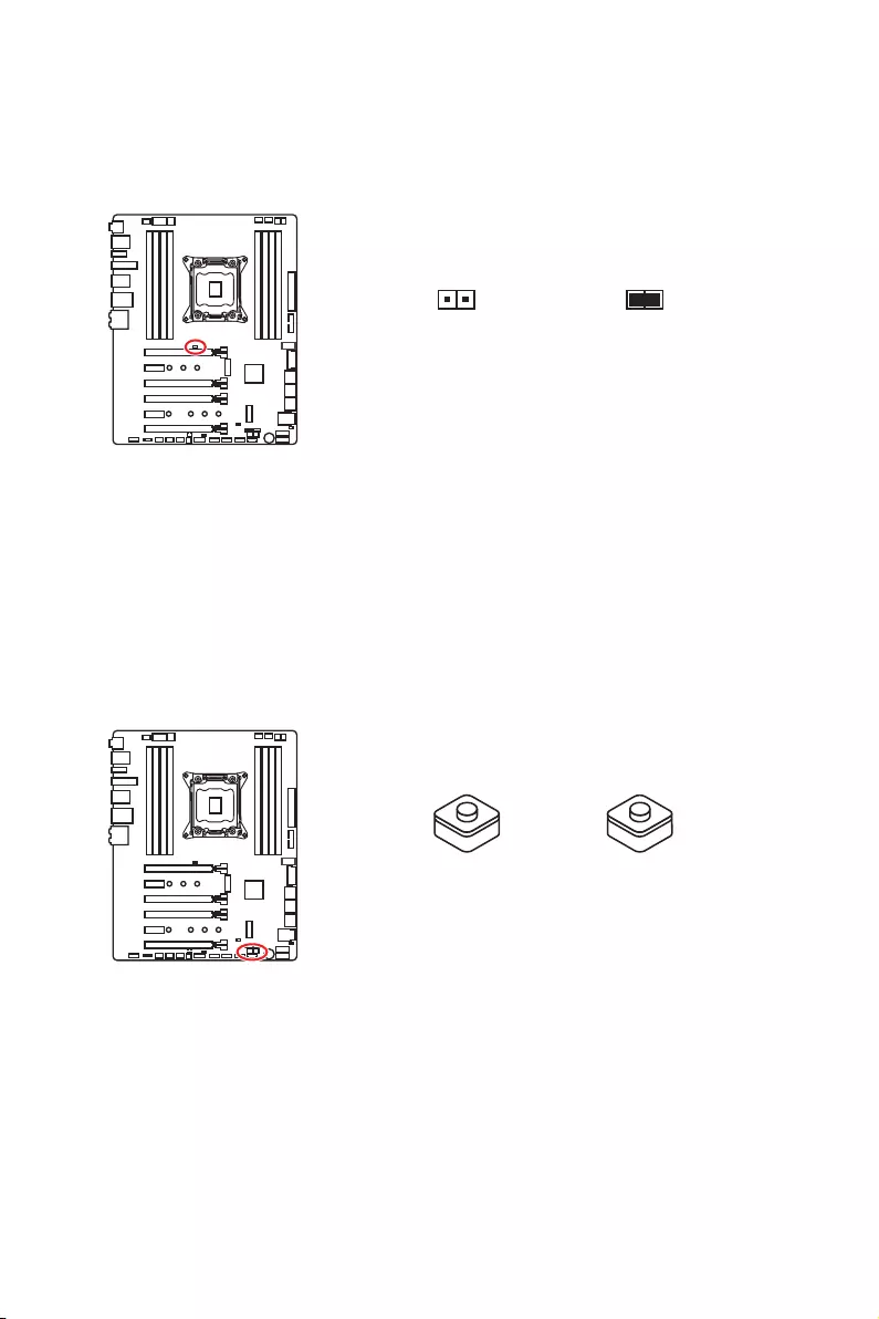
JBAT1: Clear CMOS (Reset BIOS) Jumper
There is CMOS memory onboard that is external powered from a battery located on
the motherboard to save system configuration data. If you want to clear the system
configuration, set the jumper to clear the CMOS memory.
Resetting BIOS to default values
1. Power off the computer and unplug the power cord
2. Use a jumper cap to short JBAT1 for about 5-10 seconds.
3. Remove the jumper cap from JBAT1.
4. Plug the power cord and power on the computer.
Power button Reset button
50 Overview of Components
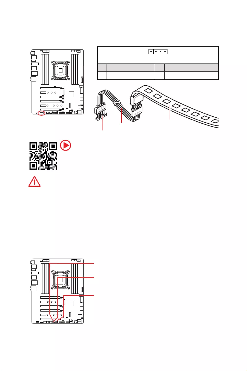
JLED1: RGB LED connector
These connectors allow you to connect the 5050 RGB LED strips.
Important
y
This connector supports 5050 RGB multi-color LED strips (12V/G/R/B) with the
maximum power rating of 3A (12V). Please keeping the LED strip shorter than 2
meters to prevent dimming.
y
Always turn off the power supply and unplug the power cord from the power outlet
before installing or removing the RGB LED strip.
y
Please use MSI’s software to control the extended LED strip.
1
JLED1
Extension cable 5050 LED strip
1
1 +12V 2 G
3 R 4 B
LED light effect demonstration components
These components are used by retailers to demonstrate onboard LED light effects.
JPWRLED1 — LED power input
DEMOLED1 — Change LED light effects
JSEL1 — Short: press DEMOLED1 will change color
Open: press DEMOLED1 will change effects
Video Demonstration
Watch the video to learn how to install 5050 RGB LED strips to RGB LED
connector.
https://youtu.be/CqNHyADzd2Q
51
Onboard LEDs
Onboard LEDs
EZ Debug LEDs
These LEDs indicate the status of key components during booting process. When an
error is occurred, the corresponding LED stays lit until the problem is solved.
CPU — indicates CPU is not detected or fail.
DRAM — indicates DRAM is not detected or fail.
VGA — indicates GPU is not detected or fail.
BOOT — indicates the booting device is not detected
or fail.
XMP LED
XMP LED
This LED indicates the XMP (Extreme Memory Profile) mode is enabled.
DIMM LEDs
DIMM LEDs
These LED indicate the memory modules are installed.
52 Onboard LEDs
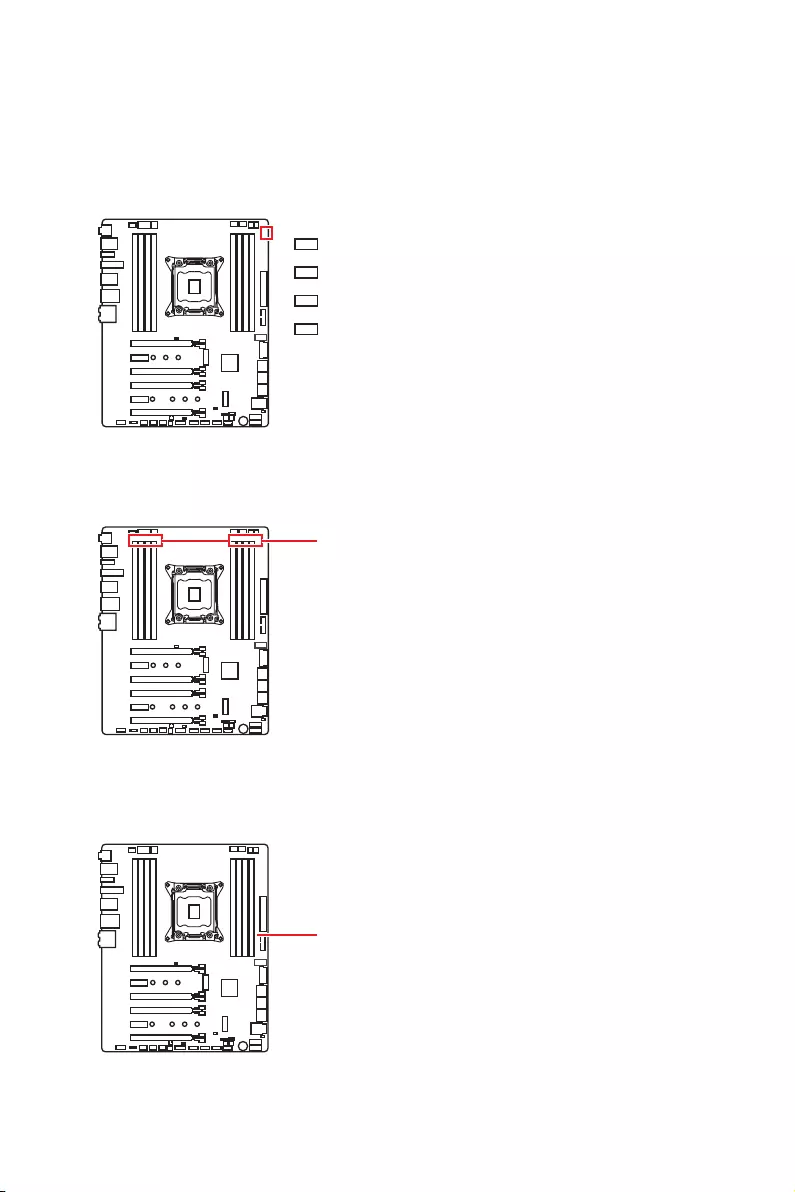
LED Color Fan control mode
Red PWM mode
Green DC mode
Fan LEDs
These LEDs indicate the fan control mode.
CPU_FAN1 LED
PUMP_FAN1 LED
PCI_E1 LED
PCI_E4 LED
PCI_E3 LED
PCI_E6 LED
PCIe x16 slot LEDs
These LED indicate the PCIe x16 slots status.
LED Color PCIe slot speed status
Red x16
White x8, x4, x1
53
Onboard LEDs
Debug Code LED
The Debug Code LED displays progress and error codes during and after POST. Refer
to the Debug Code LED table for details.
Hexadecimal Character Table
Hexadecimal 0 1 2 3 4 5 6 7 8 9 A B C D E F
Debug Code
LED display 0123456789ABCDEF
Boot Phases
Security (SEC) – initial low-level initialization
Pre-EFI Initialization (PEI) – memory initialization
Driver Execution Environment (DXE) – main hardware initialization
Boot Device Selection (BDS) – system setup, pre-OS user interface & selecting a
bootable device (CD/DVD, HDD, USB, Network, Shell, …)
Debug Code LED Table
SEC Progress Codes
01 Power on. Reset type detection (soft/
hard)
02 AP initialization before microcode loading
03 System Agent initialization before
microcode loading
04 PCH initialization before microcode
loading
06 Microcode loading
07 AP initialization after microcode loading
08 System Agent initialization after
microcode loading
09 PCH initialization after microcode loading
0B Cache initialization
SEC Error Codes
0C — 0D Reserved for future AMI SEC error codes
0E Microcode not found
0F Microcode not loaded
PEI Progress Codes
10 PEI Core is started
11 Pre-memory CPU initialization is started
12 — 14 Pre-memory CPU initialization (CPU
module specific)
15 Pre-memory System Agent initialization
is started
16 — 18 Pre-Memory System Agent initialization
(System Agent module specific)
19 Pre-memory PCH initialization is started
1A — 1C Pre-memory PCH initialization (PCH
module specific)
2B Memory initialization. Serial Presence
Detect (SPD) data reading
54 Onboard LEDs
2C Memory initialization. Memory presence
detection
2D Memory initialization. Programming
memory timing information
2E Memory initialization. Configuring
memory
2F Memory initialization (other)
31 Memory Installed
32 CPU post-memory initialization is started
33 CPU post-memory initialization. Cache
initialization
34
CPU post-memory initialization.
Application Processor(s) (AP)
initialization
35 CPU post-memory initialization. Boot
Strap Processor (BSP) selection
36 CPU post-memory initialization. System
Management Mode (SMM) initialization
37 Post-Memory System Agent initialization
is started
38 — 3A Post-Memory System Agent initialization
(System Agent module specific)
3B Post-Memory PCH initialization is started
3C — 3E Post-Memory PCH initialization (PCH
module specific)
4F DXE IPL is started
PEI Error Codes
50
Memory initialization error. Invalid
memory type or incompatible memory
speed
51 Memory initialization error. SPD reading
has failed
52
Memory initialization error. Invalid
memory size or memory modules do
not match
53 Memory initialization error. No usable
memory detected
54 Unspecified memory initialization error
55 Memory not installed
56 Invalid CPU type or Speed
57 CPU mismatch
58 CPU self test failed or possible CPU
cache error
59 CPU micro-code is not found or micro-
code update is failed
5A Internal CPU error
5B Reset PPI is not available
5C — 5F Reserved for future AMI error codes
DXE Progress Codes
60 DXE Core is started
61 NVRAM initialization
62 Installation of the PCH Runtime Services
63 CPU DXE initialization is started
64 — 67 CPU DXE initialization (CPU module
specific)
68 PCI host bridge initialization
69 System Agent DXE initialization is started
6A System Agent DXE SMM initialization is
started
6B — 6F System Agent DXE initialization (System
Agent module specific)
70 PCH DXE initialization is started
71 PCH DXE SMM initialization is started
72 PCH devices initialization
73 — 77 PCH DXE Initialization (PCH module
specific)
78 ACPI module initialization
79 CSM initialization
7A — 7F Reserved for future AMI DXE codes
90 Boot Device Selection (BDS) phase is
started
91 Driver connecting is started
92 PCI Bus initialization is started
93 PCI Bus Hot Plug Controller Initialization
94 PCI Bus Enumeration 32
95 PCI Bus Request Resources
96 PCI Bus Assign Resources
97 Console Output devices connect
98 Console input devices connect
99 Super IO Initialization
9A USB initialization is started
9B USB Reset
9C USB Detect
9D USB Enable
9E -9F Reserved for future AMI codes
A0 IDE initialization is started
A1 IDE Reset
A2 IDE Detect
A3 IDE Enable
A4 SCSI initialization is started
A5 SCSI Reset
A6 SCSI Detect
A7 SCSI Enable

55
Onboard LEDs
A8 Setup Verifying Password
A9 Start of Setup
AB Setup Input Wait
AD Ready To Boot event
AE Legacy Boot event
AF Exit Boot Services event
B0 Runtime Set Virtual Address MAP Begin
B1 Runtime Set Virtual Address MAP End
B2 Legacy Option ROM Initialization
B3 System Reset
B4 USB hot plug
B5 PCI bus hot plug
B6 Clean-up of NVRAM
B7 Configuration Reset (reset of NVRAM
settings)
B8 — BF Reserved for future AMI codes
DXE Error Codes
D0 CPU initialization error
D1 System Agent initialization error
D2 PCH initialization error
D3 Some of the Architectural Protocols are
not available
D4 PCI resource allocation error. Out of
Resources
D5 No Space for Legacy Option ROM
D6 No Console Output Devices are found
D7 No Console Input Devices are found
D8 Invalid password
D9 Error loading Boot Option (LoadImage
returned error)
DA Boot Option is failed (StartImage
returned error)
DB Flash update is failed
DC Reset protocol is not available
S3 Resume Progress Codes
E0 S3 Resume is stared (S3 Resume PPI is
called by the DXE IPL)
E1 S3 Boot Script execution
E2 Video repost
E3 OS S3 wake vector call
E4 — E7 Reserved for future AMI progress codes
S3 Resume Error Codes
E8 S3 Resume Failed
E9 S3 Resume PPI not Found
EA S3 Resume Boot Script Error
EB S3 OS Wake Error
EC — EF Reserved for future AMI error codes
Recovery Progress Codes
F0 Recovery condition triggered by firmware
(Auto recovery)
F1 Recovery condition triggered by user
(Forced recovery)
F2 Recovery process started
F3 Recovery firmware image is found
F4 Recovery firmware image is loaded
F5 — F7 Reserved for future AMI progress codes
Recovery Error Codes
F8 Recovery PPI is not available
F9 Recovery capsule is not found
FA Invalid recovery capsule
FB — FF Reserved for future AMI error codes
ACPI States Codes
The following codes appear after booting
and the operating system into ACPI
modes.
01 System is entering S1 sleep state
02 System is entering S2 sleep state
03 System is entering S3 sleep state
04 System is entering S4 sleep state
05 System is entering S5 sleep state
10 System is waking up from the S1 sleep
state
20 System is waking up from the S2 sleep
state
30 System is waking up from the S3 sleep
state
40 System is waking up from the S4 sleep
state
AC System has transitioned into ACPI mode.
Interrupt controller is in PIC mode.
AA System has transitioned into ACPI mode.
Interrupt controller is in APIC mode.
CPU Temperature
00 — 99 Displays current CPU temperature after
the system has fully booted into the OS.

56 BIOS Setup
BIOS Setup
The default settings offer the optimal performance for system stability in normal
conditions. You should always keep the default settings to avoid possible system
damage or failure booting unless you are familiar with BIOS.
Important
y
BIOS items are continuously update for better system performance. Therefore, the
description may be slightly different from the latest BIOS and should be for reference
only. You could also refer to the HELP information panel for BIOS item description.
y
The pictures in this chapter are for reference only and may vary from the product you
purchased.
Entering BIOS Setup
Please refer the following methods to enter BIOS setup.
yPress Delete key, when the Press DEL key to enter Setup Menu, F11 to enter Boot
Menu message appears on the screen during the boot process.
yUse MSI FAST BOOT application. Click on GO2BIOS button and choose OK. The
system will reboot and enter BIOS setup directly.
Click on GO2BIOS
Function key
F1: General Help
F2: Add/ Remove a favorite item
F3: Enter Favorites menu
F4: Enter CPU Specifications menu
F5: Enter Memory-Z menu
F6: Load optimized defaults
F7: Switch between Advanced mode and EZ mode
F8: Load Overclocking Profile
F9: Save Overclocking Profile
F10: Save Change and Reset*
F12: Take a screenshot and save it to USB flash drive (FAT/ FAT32 format only).
* When you press F10, a confirmation window appears and it provides the modification
information. Select between Yes or No to confirm your choice.

57
BIOS Setup
Resetting BIOS
You might need to restore the default BIOS setting to solve certain problems. There are
several ways to reset BIOS:
yGo to BIOS and press F6 to load optimized defaults.
yShort the Clear CMOS jumper on the motherboard.
Important
Be sure the computer is off before clearing CMOS data. Please refer to the Clear
CMOS jumper section for resetting BIOS.
Updating BIOS
Updating BIOS with M-FLASH
Before updating:
Please download the latest BIOS file that matches your motherboard model from MSI
website. And then save the BIOS file into the USB flash drive.
Updating BIOS:
1. Press Del key to enter the BIOS Setup during POST.
2. Insert the USB flash drive that contains the update file into the computer.
3. Select the M-FLASH tab and click on Yes to reboot the system and enter the flash
mode.
4. Select a BIOS file to perform the BIOS update process.
5. After the flashing process is 100% completed, the system will reboot
automatically.
Updating the BIOS with Live Update 6
Before updating:
Make sure the LAN driver is already installed and the Internet connection is set
properly.
Updating BIOS:
1. Install and launch MSI LIVE UPDATE 6.
2. Select BIOS Update.
3. Click on Scan button.
4. Click on Download icon to download and install the latest BIOS file.
5. Click Next and choose In Windows mode. And then click Next and Start to start
updating BIOS.
6. After the flashing process is 100% completed, the system will restart
automatically.

58 BIOS Setup
Updating BIOS with BIOS FLASHBACK+
Before updating:
Please download the latest BIOS file that matches your motherboard model from MSI®
website and rename the BIOS file to MSI.ROM. And then, save the MSI.ROM file to the
root of USB flash drive.
Important
Only the FAT32 format USB flash drive supports updating BIOS by BIOS FLASHBACK+.
1. Connect power supply to CPU_PWR1 and ATX_PWR1. (No other components are
necessary but power supply.)
2. Plug the USB flash drive that contains the MSI.ROM file into the BIOS
FLASHBACK+ port on rear I/O panel.
3. Press the BIOS FLASHBACK+ button to flash BIOS, and the light of BIOS
FLASHBACK+ button starts flashing.
4. After the flashing BIOS process is 100% completed, the button light would stop
flashing and would be off simultaneously.
59
BIOS Setup
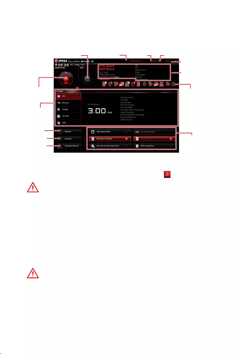
EZ Mode
At EZ mode, it provides the basic system information and allows you to configure the
basic setting. To configure the advanced BIOS settings, please enter the Advanced
Mode by pressing the Setup Mode switch or F7 function key.
Information
display
XMP switch
System
information
Boot device
priority bar
Function
buttons
Language
SearchScreenshotSetup Mode switch
M-Flash
Favorites
Hardware
Monitor
GAME BOOST
switch
yGAME BOOST switch — click on the center button to switch GAME BOOST control
between software (SW) and hardware (HW) . The inner circle represents the current
stage of hardware GAME BOOST and the outer circle stands for software. You can read
the CPU frequency of each GAME BOOST stage by clicking on the icon at right-
bottom corner.
Important
Please don’t make any changes in OC menu and don’t load defaults to keep the
optimal performance and system stability after activating the GAME BOOST function.
yXMP switch — click on the inner circle to enable/ disable the X.M.P. (Extreme Memory
Profile). Switch the outer circle to select the X.M.P. profile. This switch will only be
available if the X.M.P. supported memory module is installed.
ySetup Mode switch — press this tab or the F7 key to switch between Advanced mode
and EZ mode.
yScreenshot — click on this tab or the F12 key to take a screenshot and save it to USB
flash drive (FAT/ FAT32 format only).
ySearch — click on this tab or the Ctrl+F keys and the search page will show. It allows
you to search by BIOS item name, enter the item name to find the item listing. Move
the mouse over a blank space and right click the mouse to exit search page.
Important
In search page, only the F6, F10 and F12 function keys are available.
yLanguage — allows you to select the language of BIOS setup.
ySystem information — shows the CPU/ DDR speed, CPU/ MB temperature, MB/ CPU
type, memory size, CPU/ DDR voltage, BIOS version and build date.
yBoot device priority bar — you can move the device icons to change the boot priority.
The boot priority from high to low is left to right.

60 BIOS Setup
yInformation display — click on the CPU, Memory, Storage, Fan Info and Help buttons
on left side to display related information.
yFunction buttons — enable or disable the LAN Option ROM, M.2/Optane Genie, HD
audio controller, AHCI, RAID, CPU Fan Fail Warning Control and BIOS Log Review by
clicking on their respective button.
yM-Flash — click on this button to display the M-Flash menu that provides the way to
update BIOS with a USB flash drive.
yHardware Monitor — click on this button to display the Hardware Monitor menu that
allows you to manually control the fan speed by percentage.
yFavorites — press the Favorites tab or the F3 key to enter Favorites menu. It allows
you to create personal BIOS menu where you can save and access favorite/ frequently-
used BIOS setting items.
Default HomePage — allows you to select a BIOS menu (e.g. SETTINGS, OC…,etc)
as the BIOS home page.
Favorite1~5 — allows you to add the frequently-used/ favorite BIOS setting items
in one page.
To add a BIOS item to a favorite page (Favorite 1~5)
1. Move the mouse over a BIOS item not only on BIOS menu but also on search
page.
2. Right-click or press F2 key.
3. Choose a favorite page and click on OK.
To delete a BIOS item from favorite page
1. Move the mouse over a BIOS item on favorite page (Favorite 1~5)
2. Right-click or press F2 key.
3. Choose Delete and click on OK.
61
BIOS Setup
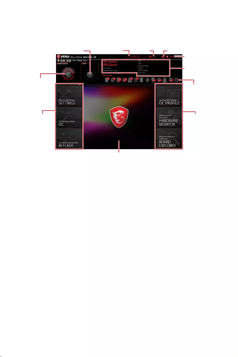
Advanced Mode
Press Setup Mode switch or F7 function key can switch between EZ Mode and
Advanced Mode in BIOS setup.
GAME BOOST
switch
XMP switch
System
information
Boot device
priority bar
Language
SearchScreenshotSetup Mode switch
Menu display
BIOS menu
selection
yGAME BOOST switch/ XMP switch/ Setup Mode switch/ Screenshot/ Favorites/
Language/ System information/ Boot device priority bar — please refer to the
descriptions of EZ Mode Overview section.
yBIOS menu selection — the following options are available:
SETTINGS — allows you to specify the parameters for chipset and boot devices.
OC — allows you to adjust the frequency and voltage. Increasing the frequency may
get better performance.
M-FLASH — provides the way to update BIOS with a USB flash drive.
OC PROFILE — allows you to manage overclocking profiles.
HARDWARE MONITOR — allows you to set the speeds of fans and monitor voltages
of system.
BOARD EXPLORER — provides the information of installed devices on this
motherboard.
yMenu display — provides BIOS setting items and information to be configured.

62 BIOS Setup
SETTINGS
System Status
fSystem Date
Sets the system date. Use tab key to switch between date elements.
The format is <day> <month> <date> <year>.
<day> Day of the week, from Sun to Sat, determined by BIOS. Read-only.
<month> The month from Jan. through Dec.
<date> The date from 1 to 31 can be keyed by numeric function keys.
<year> The year can be adjusted by users.
fSystem Time
Sets the system time. Use tab key to switch between time elements.
The time format is <hour> <minute> <second>.
fSATA PortX/ M2_X/ U2_X
Shows the information of connected SATA/ M.2/ U.2 devices.
Important
If the connected SATA device is not displayed, turn off computer and re-check SATA
cable and power cable connections of the device and motherboard.
fSystem Information
Shows detailed system information, including CPU type, BIOS version, and Memory
(read only).
fDMI Information
Shows system information, desktop Board Information and chassis Information. (Read
only).
Advanced
fPCI Subsystem Settings
Sets PCI express interface protocol and latency timer. Press Enter to enter the sub-
menu.

63
BIOS Setup
fPEGX — Max Link Speed [Auto]
Sets PCI Express protocol of PCIe x16 slots for matching different installed devices.
[Auto] This item will be configured automatically by BIOS.
[Gen1] Enables PCIe Gen1 support only.
[Gen2] Enables PCIe Gen2 support only.
[Gen3] Enables PCIe Gen3 support only.
fPCI Latency Timer [32]
Sets latency timer of PCI interface device.
[Options: 32, 64, 96, 128, 160, 192, 224, 248 PCI Bus clocks]
fAbove 4G memory/ Crypto Currency mining [Disabled]
Enables or disables 64-bit capable devices to be decoded in above 4G address
space. It is only available if the system supports 64-bit PCI decoding.
[Enabled] Allows you to utilize more than 4x GPUs.
[Disabled] Disables this function.
fACPI Settings
Sets ACPI parameters of onboard power LED behaviors. Press Enter to enter the sub-
menu.
fPower LED [Blinking]
Sets shining behaviors of the onboard Power LED.
[Dual Color] The power LED turns to another color to indicate the S3 state.
[Blinking] The power LED blinks to indicate the S3 state.
fIntegrated Peripherals
Sets integrated peripherals’ parameters, such as LAN, HDD, USB and audio. Press
Enter to enter the sub-menu.
fOnboard LAN Controller [Enabled]
Enables or disables the onboard LAN controller.
fLAN Option ROM [Disabled]
Enables or disables the legacy network Boot Option ROM for detailed settings. This
item will appear when Onboard LAN Controller is enabled.
[Enabled] Enables the onboard LAN Boot ROM.
[Disabled] Disables the onboard LAN Boot ROM.
fNetwork Stack [Disabled]
Sets UEFI network stack for optimizing IPv4 / IPv6 function.
[Enabled] Enables UEFI network stack.
[Disabled] Disables UEFI network stack.
fIpv4 PXE Support [Enabled]
When Enabled, the system UEFI network stack will support Ipv4 protocol. This item
will appear when Network Stack is enabled.
[Enabled] Enables the Ipv4 PXE boot support.
[Disabled] Disables the Ipv4 PXE boot support.

64 BIOS Setup
fIpv6 PXE Support [Enabled]
When Enabled, the system UEFI network stack will support Ipv6 protocol. This item
will appear when Network Stack is enabled.
[Enabled] Enables the Ipv6 PXE boot support.
[Disabled] Disables the Ipv6 PXE boot support.
fSATA Mode [AHCI Mode]
Sets the operation mode of the onboard SATA controller.
[AHCI Mode] Specify the AHCI mode for SATA storage devices. AHCI (Advanced
Host Controller Interface) offers some advanced features to enhance
the speed and performance of SATA storage device, such as Native
Command Queuing (NCQ) and hot-plugging.
[RAID Mode] Enables RAID function for SATA storage devices.
fM2_1/ M2_2-RST Pcie Storage Remapping [Disabled]
Enables or disables Intel Rapid Storage Technology for M.2 PCIe devices.
fM.2/Optane Genie [Disabled]
Enables or disables Intel RST support for M.2 SSDs or Optane memory.
fSATAx Hot Plug [Disabled]
Allows user to enable or disable the SATA hot plug support.
[Enabled] Enables hot plug support for the SATA ports.
[Disabled] Disables hot plug support for the SATA ports.
fHD Audio Controller [Enabled]
Enables or disables the onboard High Definition Audio controller.
fHPET [Enabled]
Enables or disables the HPET (High Precision Event Timers) support.
fUSB Configuration
Sets the onboard USB controller and device function. Press Enter to enter the sub-
menu.
fUSB Controller [Enabled]
Enables or disables all USB controller.
fXHCI Hand-off [Diasbled]
Enables or disables XHCI hand-off support for the operating system without XHCI
hand-off feature.
fLegacy USB Support [Enabled]
Sets Legacy USB function support.
[Auto] The system will automatically detect if any USB device is connected
and enable the legacy USB support.
[Enabled] Enable the USB support under legacy mode.
[Disabled] The USB devices will be unavailable under legacy mode.
fPower Management Setup
Sets system Power Management of EuP2013 and AC Power Loss behaviors. Press
Enter to enter the sub-menu.

65
BIOS Setup
fRestore after AC Power Loss [Power Off]
Sets the system behaviors while encountering the AC power loss.
[Power Off] Leaves the system in power off state after restoring AC power.
[Power On] Boot up the system after restoring AC power.
[Last State] Restores the system to the previous state (power on/ power off)
before AC power loss.
fSystem Power Fault Protection [Disabled]
Enables or disables the system to boot up when detecting abnormal voltage input.
[Enabled] Protect the system from unexpected power operation and remain
the shut down status.
[Disabled] Disables this function.
fWindows OS Configuration
Sets Windows OS detailed configuration and behaviors. Press Enter to enter the sub-
menu.
fWindows 10 WHQL Support [Disabled]
Enables the supports for Windows 10 or disables for other operating systems.
Before enabling this item, make sure all installed devices & utilities (hardware &
software) should meet the Windows 10 requirements.
[Enabled] The system will switch to UEFI mode to meet the Windows
equirement.
[Disabled] Disables this function.
fMSI Fast Boot [Disabled]
MSI Fast Boot is the fastest way to boot the system. It will disable more devices to
speed up system boot time which is faster than the boot time of Fast Boot.
[Enabled] Enables the MSI Fast Boot function to speed up booting time. And
the following Fast Boot field will be disabled and fixed.
[Disabled] Disables MSI Fast Boot.
Important
When MSI Fast Boot is enabled, you can use MSI FAST BOOT application to enter BIOS
setup if needed. Please refer Entering BIOS Setup section for details.
fFast Boot [Enabled]
Enables or disables the fast boot feature for Windows 10. This item will only be
available when MSI Fast Boot is disabled.
[Enabled] Enables the Fast Boot configuration to accelerate system boot time.
[Disabled] Disables the Fast Boot configuration.
fSecure Boot
Sets the Windows secure boot to prevent the unauthorized accessing. Press Enter
to enter the sub-menu. This sub-menu will appear when Windows 10 WHQL
Support is enabled.
fSecure Boot Support [Disabled]
Enables or disables secure boot support.
[Enabled] Enables the secure boot function and allow you to set the secure
boot settings.
[Disabled] Disables this function.

66 BIOS Setup
fSecure Boot Mode [Standard]
Selects the secure boot mode. This item is to select how the secure boot keys be
loaded. This item appears when Secure Boot Support is enabled.
[Standard] The system will automatically load the secure keys from BIOS.
[Custom] Allows user to configure the secure boot settings and manually load
the secure keys.
fKey Management
Manages the secure boot keys. Press <Enter> to enter the sub-menu. This sub-
menu will appear when Secure Boot Mode sets to Custom.
fWake Up Event Setup
Sets system wake up behaviors for different sleep modes. Press Enter to enter the
sub-menu.
fWake Up Event By [BIOS]
Selects the wake up event by BIOS or operating system.
[BIOS] Activates the following items, set wake up events of these items.
[OS] The wake up events will be defined by OS.
fResume By RTC Alarm [Disabled]
Disables or enables the system wake up by RTC Alarm.
[Enabled] Enables the system to boot up on a scheduled time/ date.
[Disabled] Disables this function.
fDate (of month) Alarm/ Time (hh:mm:ss) Alarm
Sets RTC alarm date/ Time. If Resume By RTC Alarm is set to [Enabled], the system
will automatically resume (boot up) on a specified date/hour/minute/second in
these fields (using the + and — keys to select the date & time settings).
fResume By PCI-E Device [Disabled]
Enables or disables the wake up function of installed PCI-E expansion cards,
integrated LAN controllers or USB devices which are supported by third party
integrated chips.
[Enabled] Enables the system to be awakened from the power saving modes
when activity or input signal of PCIe device is detected.
[Disabled] Disables this function.
fResume By Onboard Intel LAN [Disabled]
Enables or disables the system wake up by Onboard Intel LAN.
[Enabled] Enables the system to be awakened from the power saving modes
when activity or input signal of Intel LAN device is detected.
[Disabled] Disables this function.
fResume by USB Device [Disabled]
Enables or disables the system wake up by USB devices.
[Enabled] Enables the system to be awakened from sleep state when activity of
USB device is detected.
[Disabled] Disables this function.

67
BIOS Setup
fResume From S3/S4/S5 by PS/2 Mouse [Disabled]
Enables or disables the system wake up by PS/2 mouse.
[Enabled] Enables the system to be awakened from S3/ S4/ S5 state when
activity of PS/2 mouse is detected.
[Disabled] Disables this function.
fResume From S3/S4/S5 by PS/2 Keyboard [Disabled]
Enables or disables the system wake up by PS/2 keyboard.
[Any Key] Enables the system to be awakened from S3/ S4/ S5 state when
activity of any key on PS/2 keyboard is detected.
[Hot Key] Enables the system to be awakened from S3/ S4/ S5 state when
activity of hot key on PS/2 keyboard is detected.
[Disabled] Disables this function.
fHot Key [Ctrl+Space]
Selects a combination of keys as a hot key to wake the system. This item appears
when you set the Resume From S3/S4/S5 by PS/2 Keyboard to Hot Key.
fSecure Erase+
Enables or disables Secure Erase+ function. Secure Erase+ is the best way to
effectively wipe all data from a SSD. Please note that data of SSD will be erased after
enabling Secure Erase+.
fIntel ( R ) Ethernet Connection 1219-V
Shows driver information and configuration of the ethernet controller parameter.
Boot
Sets the sequence of system boot devices.
fFull Screen Logo Display [Enabled]
Enables or disables to show the full screen logo while system POST.
[Enabled] Shows the logo in full screen.
[Disabled] Shows the POST messages.
fGO2BIOS [Disabled]
Allows system to enter BIOS setup directly by pressing the Power button for 4 sec pon
bootup.
[Enabled] The system boots straight to the BIOS setup by long pressing the power
button about 4 seconds when the system is off.
[Disabled] Disables this function.
fBootup NumLock State [On]
Select the keyboard NumLock state upon bootup.
fInfo Block effect [Unlock]
Sets the state of Help information block.
[Unlock] Sliding effect.
[Lock] Fix the Help information block on the screen.

68 BIOS Setup
fAUTO CLR_CMOS [Disabled]
Enables or disables the CMOS data to be resumed automatically when the booting
process hang-up over 5 seconds.
fBoot Mode Select [LEGACY+UEFI]
Sets the system boot mode from legacy or UEFI architecture depending on OS
installation requirement. This item will become un-selectable and will be configured
automatically by BIOS when Windows 8.1/ 10 WHQL Support is enabled.
[UEFI] Enables UEFI BIOS boot mode support only.
[LEGACY+UEFI] Enables both Legacy BIOS boot mode and UEFI BIOS boot
mode.
fFIXED BOOT ORDER Priorities
Sets device priority for system boot.
fBoot Option Priorities
These items are used to prioritize the installed boot devices.
Security
fAdministrator Password
Sets administrator password for system security. User has full rights to change the
BIOS items with administrator password. After setting the administrator password, the
state of this item will show Installed.
fUser Password
Sets User Password for system security. User has limited rights to change the BIOS
items with user password. This item will be available when administrator password is
set. After setting the user password, the state of this item will show Installed.
fPassword Check [Setup]
Selects a condition that will request the password.
[Setup] A password will be requested for entering the BIOS Setup.
[Boot] A password will be requested for booting the system.
fPassword Clear [Enabled]
Enables or disables the clear CMOS behavior to clear a set password.
[Enabled] The password will be erased after clear CMOS.
[Disabled] The password will always be kept.
Important
y
When selecting the Administrator / User Password items, a password box will
appear on the screen. Type the password then press Enter. The password typed now
will replace any previous set password from CMOS memory. You will be prompted to
confirm the password. You may also press Esc key to abort the selection.
y
To clear a set password, press Enter when you are prompted to enter a new
password. A message will confirm the password is being disabled. Once the password
is disabled, you can enter the setup and OS without authorization.

69
BIOS Setup
fTrusted Computing
Sets TPM (Trusted Platform Module) function.
fSecurity Device Support [Disabled]
Enables or disables the TPM function to build the endorsement key for accessing
the system.
fChassis Intrusion Configuration
Press <Enter> to enter the sub-menu.
fChassis Intrusion [Disabled]
Enables or disables recording messages when the chassis is opened. This function
is ready for the chassis equips a chassis intrusion switch.
[Enabled] Once the chassis is opened, the system will record and issue a
warning message.
[Reset] Clear the warning message. After clearing the message, please
return to Enabled or Disabled.
[Disabled] Disables this funcion.
Save & Exit
fDiscard Changes and Exit
Exit BIOS setup without saving any change.
fSave Changes and Reboot
Save all changes and reboot the system.
fSave Changes
Save current changes.
fDiscard Changes
Discard all changes and restore to the previous values.
fRestore Defaults
Restore or load all default values.
fBoot Override
The installed bootable devices will appear on this menu, you can select one of them to
be the boot device.

70 BIOS Setup
OC
Important
y
Overclocking your PC manually is only recommended for advanced users.
y
Overclocking is not guaranteed, and if done improperly, it could void your warranty or
severely damage your hardware.
y
If you are unfamiliar with overclocking, we advise you to use GAME BOOST function
for easy overclocking.
fOC Explore Mode [Normal]
Enables or disables to show the normal or expert version of OC settings.
[Normal] Provides the regular OC settings in BIOS setup.
[Expert] Provides the advanced OC settings for OC expert to configure in BIOS
setup.
Note: We use * as the symbol for the OC settings of Expert mode.
fCPU Ratio Apply Mode [All Core]*
Sets applied mode for CPU ratio. This item only appears when a CPU that supports
Turbo Boost is installed.
[All Core] Activate the CPU Ratio field. All CPU cores will run the same CPU ratio
that be set in CPU Ratio.
[Per Core] Activate the X-Core Ratio Limit field. Sets each CPU core ratio
separately in X-Core Ratio Limit.
fCPU Ratio [Auto]
Sets the CPU ratio that is used to determine CPU clock speed. This item can only be
changed if the processor supports this function.
fAdjusted CPU Frequency
Shows the adjusted CPU frequency. Read-only.

71
BIOS Setup
fCPU Ratio Mode [Dynamic Mode]*
Selects the CPU Ratio operating mode. This item will appear when you set the CPU
ratio manually.
[Fixed Mode] Fixes the CPU ratio.
[Dynamic Mode] CPU ratio will be changed dynamically according to the CPU
loading.
fCPU Ratio Offset When Running AVX [Auto]
Sets a offset value to lower the CPU core ratio. It could be helpful for heat dissipation
when running AVX instruction set. If set to Auto, BIOS will configure this setting
automatically. This item appears when the installed CPU supports this function.
fRing Ratio [Auto]
Sets the ring ratio. The valid value range depends on the installed CPU.
fAdjusted Ring Frequency
Shows the adjusted Ring frequency. Read-only.
fMisc Setting*
Press Enter, + or — key to open or close the following 3 items related to CPU features.
fEIST [Enabled]*
Enables or disables the Enhanced Intel® SpeedStep Technology.
[Enabled] Enables the EIST to adjust CPU voltage and core frequency
dynamically. It can decrease average power consumption and
average heat production.
[Disabled] Disables EIST.
fIntel Turbo Boost [Enabled]*
Enables or disables the Intel® Turbo Boost. This item appears when the installed
CPU supports this function.
[Enabled] Enables this function to boost CPU performance automatically above
rated specifications when system request the highest performance
state.
[Disabled] Disables this function.
fEnhanced Turbo [Auto]*
Enables or disables Enhanced Turbo function for all CPU cores to boost CPU
performance. This item appears when the installed CPU supports this function.
[Auto] This setting will be configured automatically by BIOS.
[Enabled] All CPU cores would be increased to maximum turbo ratio.
[Disabled] Disables this function.
fExtreme Memory Profile (X.M.P.) [Disabled]
X.M.P. (Extreme Memory Profile) is the overclocking technology by memory module.
Please enable XMP or select a profile of memory module for overclocking the memory.
This item will be available when the memory modules that support X.M.P. is installed.
fDRAM Reference Clock [Auto]*
Sets the DRAM reference clock. The valid value range depends on the installed CPU.
This item appears when a CPU that supports this adjustment is installed.

72 BIOS Setup
fDRAM Frequency [Auto]
Sets the DRAM frequency. Please note the overclocking behavior is not guaranteed.
fAdjusted DRAM Frequency
Shows the adjusted DRAM frequency. Read-only.
fDRAM Timing Mode [Link]
Selects the memory timing mode.
[Link] Allows user to configure the DRAM timing for all memory channel.
[UnLink] Allows user to configure the DRAM timing for respective memory
channel.
fAdvanced DRAM Configuration
Press Enter to enter the sub-menu. User can set the memory timing for each/ all
memory channel. The system may become un-stable or un-bootable after changing
memory timing. If it occurs, please clear the CMOS data and restore the default
settings. (Refer to the Clear CMOS jumper/ button section to clear the CMOS data, and
enter the BIOS to load the default settings.)
fMemory Fast Boot [Auto]*
Enables or disables the initiation and training for memory every booting.
[Auto] The setting will be configured automatically by BIOS.
[Enabled] System will completely keep the archives of first intiation and training
for memory. So the memory will not be initialed and trained when
booting to accelerate the system booting time.
[Disabled] The memory will be initialed and trained every booting.
fDigitALL Power
Press Enter to enter the sub-menu. Controls the digital powers related to CPU PWM.
fSVID Communication [Auto]*
Enables or disables SVID (Serial Voltage Identification) support.
[Auto] This setting will be configured automatically by BIOS.
[Enabled] PWM phase will be changed dynamically according to the CPU SVID
(Serial Voltage Identification).
[Disabled] Disables SVID (Serial Voltage Identification) support.
fVCCIN Voltage [Auto]
Sets the CPU input voltage. The CPU input voltage is the CPU power source that is
shared with components of the CPU.
fCPU Voltages control [Auto]
These options allows you to set the voltages related to CPU. If set to Auto, BIOS will
set these voltages automatically or you can set it manually.
fDRAM Voltages control [Auto]
These options allows you to set the voltages related to memory. If set to Auto, BIOS
will set these voltages automatically or you can set it manually.
fPCH Voltages control [Auto] (optional)
These options allows you to set the voltages related to PCH. If set to Auto, BIOS will
set these voltages automatically or you can set it manually.

73
BIOS Setup
fCPU Memory Changed Detect [Enabled]*
Enables or disables the system to issue a warning message during boot when the CPU
or memory has been replaced.
[Enabled] The system will issue a warning message during boot and than needs to
load the default settings for new devices.
[Disabled] Disables this function and keeps the current BIOS settings.
fCPU Specifications
Press Enter to enter the sub-menu. This sub-menu displays the information of
installed CPU. You can also access this information menu at any time by pressing [F4].
Read only.
fCPU Technology Support
Press Enter to enter the sub-menu. The sub-menu shows the key features of
installed CPU. Read only.
fMEMORY-Z
Press Enter to enter the sub-menu. This sub-menu displays all the settings and
timings of installed memory. You can also access this information menu at any time by
pressing [F5].
fDIMMx Memory SPD
Press Enter to enter the sub-menu. The sub-menu displays the information of
installed memory. Read only.
fCPU Features
Press Enter to enter the sub-menu.
fHyper-Threading [Enabled]
Intel Hyper-Threading technology treats the multi cores inside the processor as
multi logical processors that can execute instructions simultaneously. In this way,
the system performance is highly improved. This item appears when the installed
CPU supports this technology.
[Enable] Enables Intel Hyper-Threading technology.
[Disabled] Disables this item if the system does not support HT function.
fLimit CPUID Maximum [Disabled]
Enables or disables the extended CPUID value.
[Enabled] BIOS limits the maximum CPUID input value to circumvent boot
problems with older operating system that do not support the
processor with extended CPUID value.
[Disabled] Use the actual maximum CPUID input value.
fIntel Virtualization Tech [Enabled]
Enables or disables Intel Virtualization technology.
[Enabled] Enables Intel Virtualization technology and allows a platform to run
multiple operating systems in independent partitions. The system
can function as multiple systems virtually.
[Disabled] Disables this function.
fIntel VT-D Tech [Disabled]
Enables or disables Intel VT-D (Intel Virtualization for Directed I/O) technology.

74 BIOS Setup
fHardware Prefetcher [Enabled]
Enables or disables the hardware prefetcher (MLC Streamer prefetcher).
[Enabled] Allows the hardware prefetcher to automatically pre-fetch data
and instructions into L2 cache from memory for tuning the CPU
performance.
[Disabled] Disables the hardware prefetcher.
fAdjacent Cache Line Prefetch [Enabled]
Enables or disables the CPU hardware prefetcher (MLC Spatial prefetcher).
[Enabled] Enables adjacent cache line prefetching for reducing the cache
latency time and tuning the performance to the specific application.
[Disabled] Enables the requested cache line only.
fCPU AES Instructions [Enabled]
Enables or disables the CPU AES (Advanced Encryption Standard-New
Instructions) support. This item appears when a CPU supports this function.
fIntel Adaptive Thermal Monitor [Enabled]
Enables or disables the Intel adaptive thermal monitor function to protect the CPU
from overheating.
[Enabled] Throttles down the CPU core clock speed when the CPU is over the
adaptive temperature.
[Disabled] Disables this function.
fIntel C-State [Auto]
Enables or disables the Intel C-state. C-state is a processor power management
technology defined by ACPI.
[Auto] This setting will be configured automatically by BIOS.
[Enabled] Detects the idle state of system and reduce CPU power consumption
accordingly.
[Disabled] Disable this function.
fC1E Support [Disabled]
Enables or disables the C1E function for power-saving in halt state. This item
appears when Intel C-State is enabled.
[Enabled] Enables C1E function to reduce the CPU frequency and voltage for
power-saving in halt state.
[Disabled] Disables this function.
fPackage C State Limit [Auto]
This item allows you to select a CPU C-state level for power-saving when system is
idle. The options of C-state depend on the installed CPU. This item appears when
Intel C-State is enabled.
fCFG Lock [Enabled]
Lock or un-lock the MSR 0xE2[15], CFG lock bit.
[Enabled] Locks the CFG lock bit.
[Disabled] Un-locks the CFG lock bit.

75
BIOS Setup
fLong Duration Power Limit (W) [Auto]
Sets the long duration TDP power limit for CPU in Turbo Boost mode.
fLong Duration Maintained (s) [Auto]
Sets the maintaining time for Long duration power Limit(W).
fShort Duration Power Limit (W) [Auto]
Sets the short duration TDP power limit for CPU in Turbo Boost mode.
fCPU Current Limit (A) [Auto]
Sets maximum current limit of CPU package in Turbo Boost mode. When the
current is over the specified value, the CPU will automatically reduce the core
frequency for reducing the current.
fInternal VR OVP OCP Protection [Auto]
Enables or disables the over-voltage protection and over-current protection for
CPU internal VR (Voltage Regulator).
[Auto] This setting will be configured automatically by BIOS.
[Enabled] Enables the limitation of internal VR for over-voltage protection and
over-current protection.
[Disabled] Disables this function for overclocking.
fInternal VR Efficiency Management [Auto]
Enables or disables the CPU internal VR efficiency management.
[Auto] This setting will be configured automatically by BIOS.
[Enabled] Enables the VR effciency management for power-saving control.
[Disabled] Disables this function.
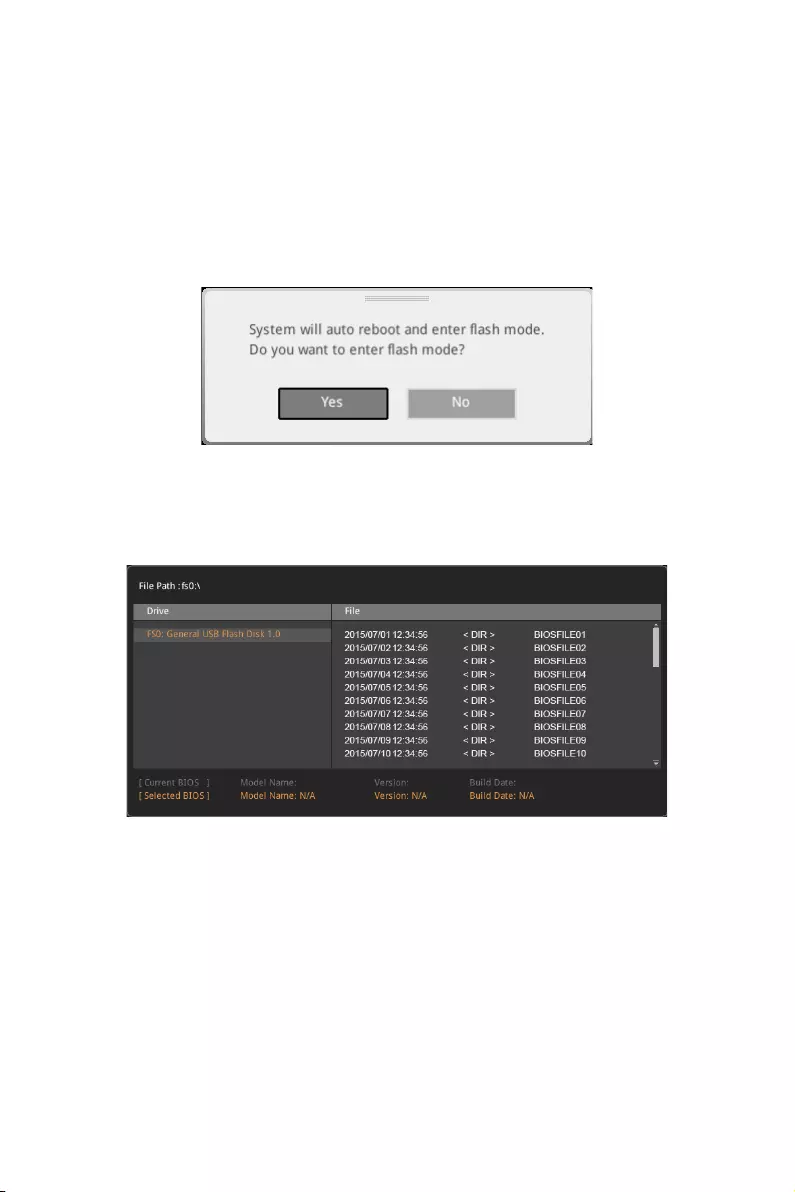
76 BIOS Setup
M-FLASH
M-FLASH provides the way to update BIOS with a USB flash drive. Please down-load
the latest BIOS file that matches your motherboard model from MSI website, save the
BIOS file into your USB flash drive. And then follow the steps below to update BIOS.
1. Insert the USB flash drive that contains the update file into the computer.
2. Click on M-FLASH tab, a demand message will be prompted. Click on Yes to
reboot and enter the flash mode.
3. The system will enter the flash mode and a file selection menu will appear after
rebooting.
4. Select a BIOS file to perform the BIOS update process.
5. After the flashing process is 100% completed, the system will reboot
automatically.

77
BIOS Setup
OC PROFILE
fOverclocking Profile 1/ 2/ 3/ 4/ 5/ 6
Overclocking Profile 1/ 2/ 3/ 4/ 5/ 6 management. Press <Enter> to enter the sub-
menu.
fSet Name for Overclocking Profile 1/ 2/ 3/ 4/ 5/ 6
Name the current overclocking profile.
fSave Overclocking Profile 1/ 2/ 3/ 4/ 5/ 6
Save the current overclocking profile.
fLoad Overclocking Profile 1/ 2/ 3/ 4/ 5/ 6
Load the current overclocking profile.
fClear Overclocking Profile 1/ 2/ 3/ 4/ 5/ 6
Clear the current overclocking profile.
fOC Profile Load from ROM
Load OC profile from BIOS ROM.
fOC Profile Save to USB
Save OC profile to the USB flash drive. The USB flash drive should be FAT/ FAT32
format only.
fOC Profile Load from USB
Load OC profile from the USB flash drive. The USB flash drive should be FAT/ FAT32
format only.

78 Software Description
Software Description
Installing Windows® 10
1. Power on the computer.
2. Insert the Windows® 10 disc into your optical drive.
3. Press the Restart button on the computer case.
4. Press F11 key during the computer POST (Power-On Self Test) to get into Boot
Menu.
5. Select your optical drive from the Boot Menu.
6. Press any key when screen shows Press any key to boot from CD or DVD…
message.
7. Follow the instructions on the screen to install Windows® 10.
Installing Drivers
1. Start up your computer in Windows® 10.
2. Insert MSI® Driver Disc into your optical drive.
3. The installer will automatically appear and it will find and list all necessary
drivers.
4. Click Install button.
5. The software installation will then be in progress, after it has finished it will
prompt you to restart.
6. Click OK button to finish.
7. Restart your computer.
Installing Utilities
Before you install utilities, you must complete drivers installation.
1. Insert MSI® Driver Disc into your optical drive.
2. The installer will automatically appear.
3. Click Utilities tab.
4. Select the utilities you want to install.
5. Click Install button.
6. The utilities installation will then be in progress, after it has finished it will prompt
you to restart.
7. Click OK button to finish.
8. Restart your computer.
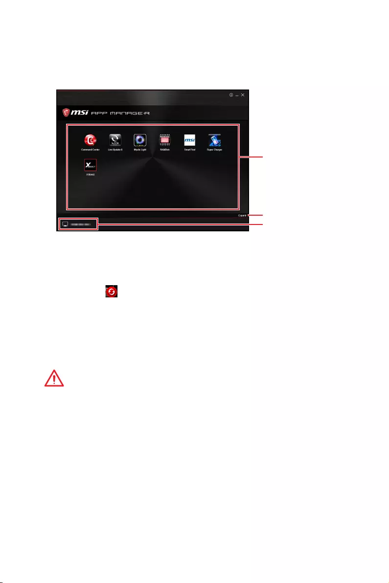
79
Software Description
APP MANAGER
APP MANAGER is a handy management application for integration of MSI applications
and software interface. Providing easy shortcut entrance and real-time update
information of all the MSI software and applications.
APP list
Total Install/ Update
Motherboard
Information
yAPP list — shows all the applications and software be supported by this motherboard.
An icon represents a entrance to the application rather than the application itself.
Colorful icon — a colorful icon means that the application had have been installed
successfully and is available. Double click on desired icon to access the application.
A refresh icon shows to inform you that the application has a update version.
Gray icon — the icon with gray painting means that the application is not available
and you have to install it if needed. Double click on the gray icon and the update
information will show. Click on the INSTALL button to install the application.
yMotherboard Information — shows the model name of motherboard.
yTotal Install/ Update — click on this tab to update/ install all the applications.
Important
Please note that, once you uninstall the APP MANAGER, all the MSI applications and
software will be uninstalled simultaneously.
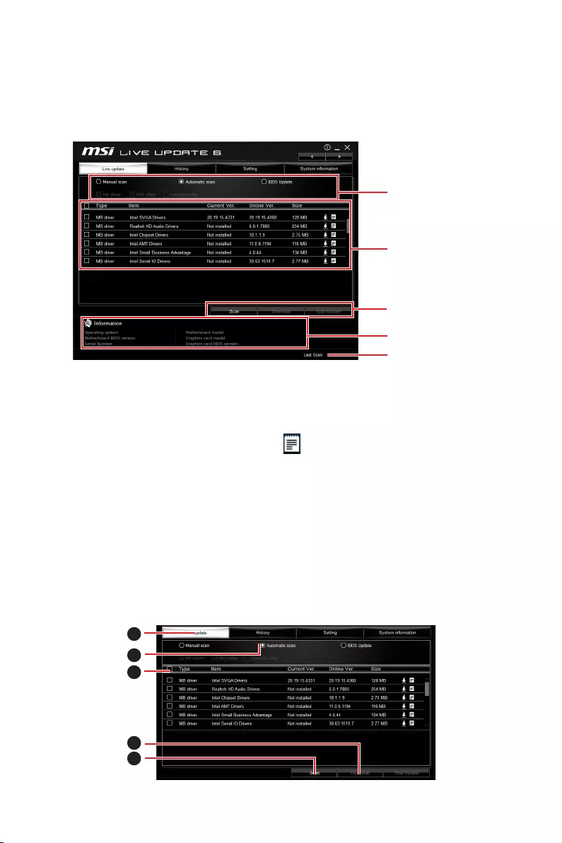
80 Software Description
LIVE UPDATE 6
LIVE UPDATE 6 is an application for the MSI® system to scan and download the latest
drivers, BIOS and utilities. With LIVE UPDATE 6, you don’t need to search the drivers
on websites, and don’t need to know the models of motherboard and graphics cards.
LIVE UPDATE 6 will download the appropriate drivers automatically.
Download Options
Download List
Scan / Download / Total
Installer button
System Information
Last Scanned Date
There are Live Update, History, Setting and System Information tabs at the top. You
can click the tab to switch the control panel.
yLive Update — When you launch LIVE UPDATE 6, you will see the Live update tab at
first. This tab allows you to select files to download. You can also read the relevant
information by clicking the information icon on the right of the item listed.
yHistory — shows the downloading history.
ySetting — allows you to specify the frequency that LIVE UPDATE 6 remind you to
update.
ySystem Information — displays the information of the system.
yFAQ — shows Frequently Asked Questions.
yOnline Help — shows Online Help information.
Updating The System
This section describes how to update your system with LIVE UPDATE 6. Please follow
the steps below:
1
2
4
5
3
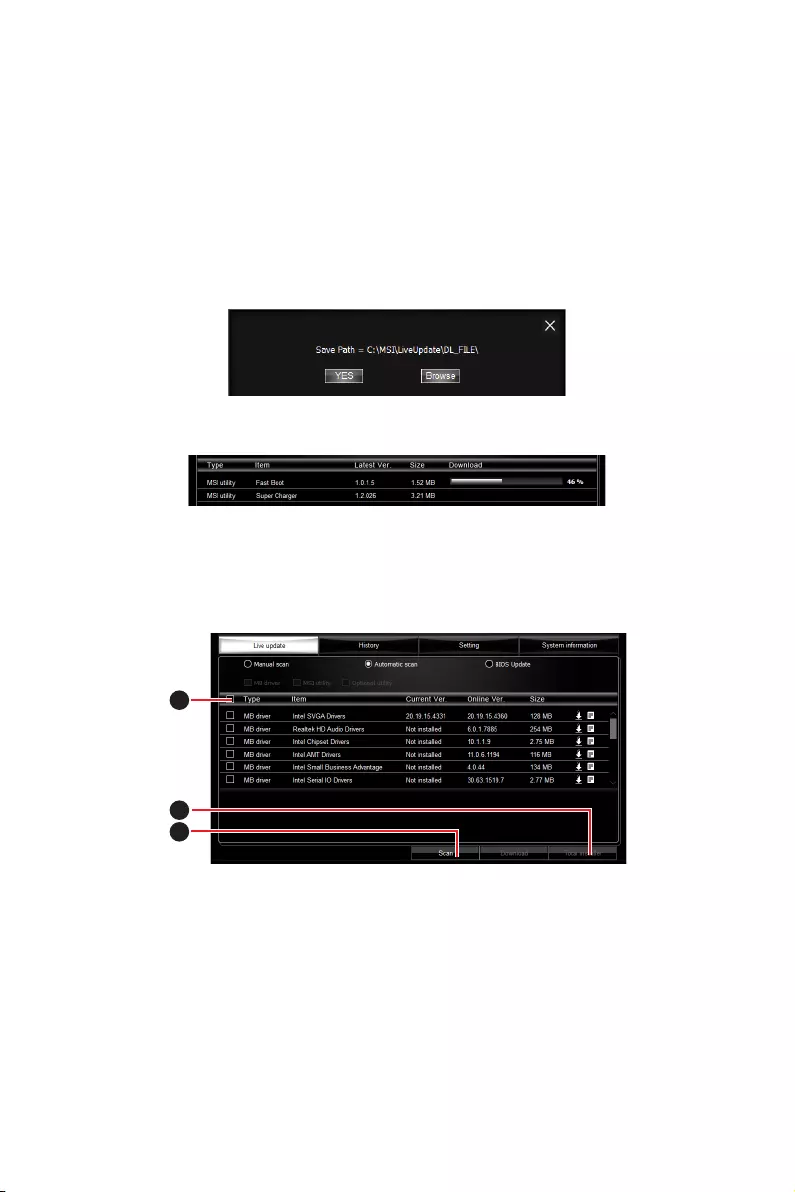
81
Software Description
1. Select the Live Update tab.
2. Choose Automatic scan, system will automatically scan all the items and search
for the latest update files. Or you can choose Manual scan and select the items you
wish to scan.
3. Click the Scan button at the bottom. It may take several moments to complete the
process.
4. When the download list appears, please select the items you intend to update.
5. Click Download button at the bottom.
6. When Save Path prompt, you can specify a download directory.
7. When downloading you will see the screen below. It may take several moments to
complete the process.
8. To install the applications, simply unpack the packages and install.
Total Installer
Total Installer is a convenient feature to simplify frequent installing procedure. To use
Total Installer:
1
2
3
1. Scan updates in Live Update tab.
2. Check the Select All check-box you intend to update.
3. Click the Total Installer button. LIVE UPDATE 6 will automatically install them.
4. When prompted, click OK to complete the Total Installer procedure
5. Reboot your system.
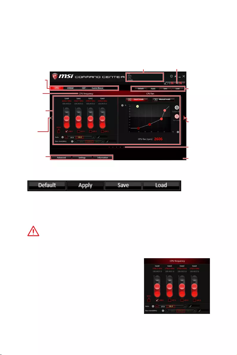
82 Software Description
COMMAND CENTER
COMMAND CENTER is an user-friendly software and exclusively developed by MSI,
helping users to adjust system settings and monitor status under OS. With the help
of COMMAND CENTER, making it possible to achieve easier and efficient monitoring
process and adjustments than that under BIOS. In addition, the COMMAND CENTER
can be a server for mobile remote control application.
Feature Menu
CPU TemperatureSystem Information
Feature Title
Feature
Control Panel
Previous
Feature
Next Feature
Profile
Buttons
Option Buttons
Page Indicator
Resize Corner
Profile Buttons
yDefault — load the default values for the current feature.
yApply — apply your changes.
ySave — store values in the file with individual file extension.
yLoad — load the values from the file.
Important
Every time you shut down the system, the configured setting will be restored to the
factory default. If you want to use the saved settings, you have to load it every time by
clicking the Load and Apply buttons.
CPU Frequency
CPU Frequency control panel allows you to change
CPU Ratio and Base clock. You can see the current
frequency of each CPU core on the top of the panel.
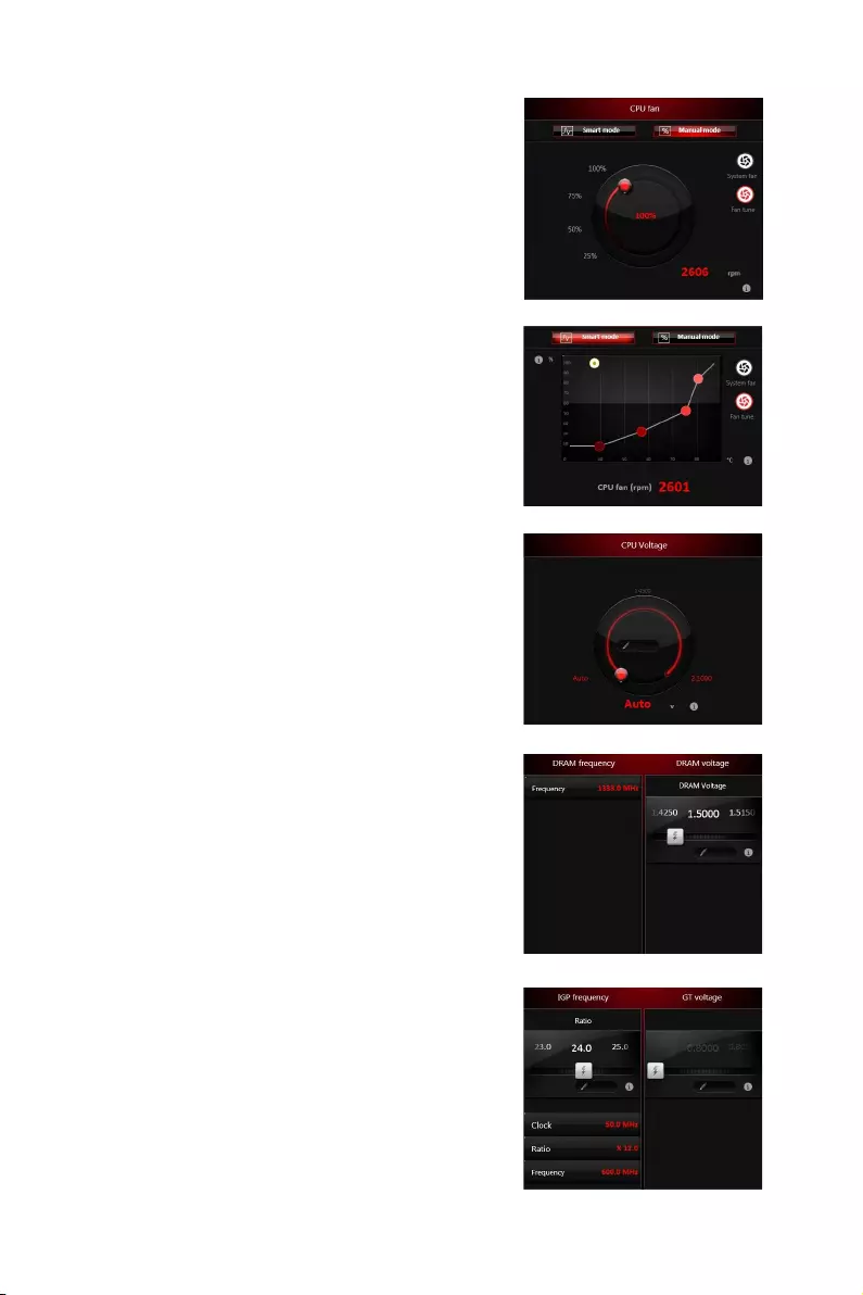
83
Software Description
CPU Fan
CPU Fan control panel provides Smart mode and
Manual Mode. You can switch the control mode by
clicking the Smart Mode and Manual Mode buttons
on the top of the CPU Fan control panel.
yManual Mode — allows you to manually control the
CPU fan speed by percentage.
ySmart Mode — a linear fan speed control feature.
The control panel contains 4 dots allows you to
drag and adjust the Smart Speed slopes. The fan
speed will be changed along these lines with CPU
temperature. The white dot will create strip chart in
real time.
ySystem Fan Button — to open the system fan control
panel in new window.
yFan Tune Button — to automatically optimize the
smart fan setting.
Manual Mode
Smart Mode
IGP Frequency & GT Voltage
yIGP Frequency — Allows you to adjust the IGP ratio,
and shows the IGP clock, ratio and frequency.
yGT Voltage — Allows you to adjust the GT voltage.
The risky values are displayed in red.
DRAM Frequency & DRAM Voltage
yDRAM Frequency — Shows the DRAM clock, ratio
and frequency.
yDRAM Voltage — Allows you to adjust the DRAM
voltage. The risky values are displayed in red.
CPU Voltage
CPU Voltage control panel allows you to control the
CPU voltage.
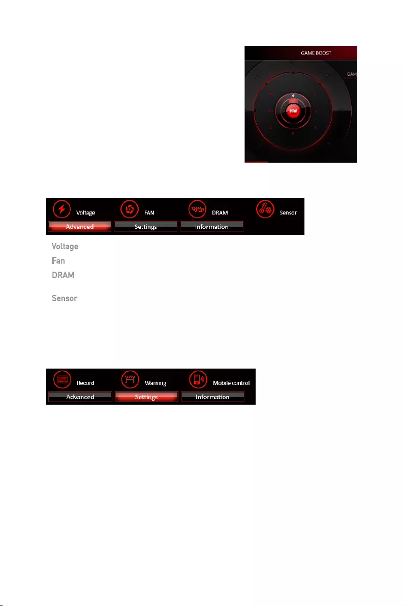
84 Software Description
Option Buttons — Advanced
When click the Advanced button, The Voltage, Fan and DRAM icons will appear.
yVoltage — allows you to adjust advanced voltage values of CPU and chipset.
yFan — allows you to control the system fans speed.
yDRAM — shows the current Advanced DRAM parameters, and allows you to change
the settings by selecting values from the drop-down menu on the right hand side.
ySensor — allows you to monitor your motherboard temperature and fan speed with
the virtual thermal image. You can drag and drop the fan icons to new locations. When
you press the Cooling button, all fans will run at full speed.
Option Buttons — Setting
When click the Setting button, The Record, Warning and Mobile Control icons will
appear.
yRecord — allows you to monitor the status of voltage, fan speed and temperature in
real time.
To filter record charts, select the check box next to the items.
When click the Play button, the chart pane will start to show the recording chart.
If you want to check the value of a specific spot on chart, please move the orange
vertical line to the spot.
History Record stores the data and names with date and time.
To make a history record: Select items and click the Record button. When
finished, click the Record button again. The data will be stored in the drop-down
menu.
To load a record, click the drop-down menu and select one from the list.
To delete a record, select the record that you want to delete, and click the Trash
Can icon.
GAME BOOST
GAME BOOST has 8 overclocking stages for you
to overclock your computer. COMMAND CENTER
provides the software interface instead of GAME
BOOST knob on the motherboard. You can click on
the center button to switch GAME BOOST control
between software (SW) and hardware (HW) . The
inner circle represents the current stage of hardware
GAME BOOST and the outer represents software.
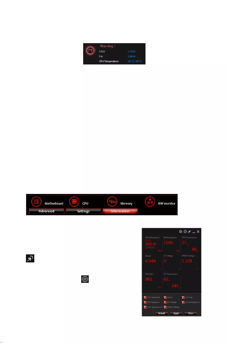
85
Software Description
yWarning — contains fields of voltage, fan speed and temperature for you to set the
threshold values. When system detects the status over your settings, a warning
message will pop-up.
yMobile Control — is only available for the motherboard with the built-in WiFi module.
It allows you to enable/disable the COMMAND CENTER Remote Server. Please refer to
the instruction on the Mobile Control control panel.
yTo start remote control: (optional)
1. Download and install MSI® COMMAND CENTER APP to your mobile device.
2. Enable COMMAND CENTER Remote Server on the Mobile Control panel.
3. Enable SoftAP Management.
4. Enter SSID and Password, and then click the Apply button.
5. Activate Wi-Fi® on your mobile device and connect to SoftAP with the SSID.
6. Run MSI® COMMAND CENTER APP on your mobile device.
7. Find the IP address on the SoftAP Management Setting area, and enter the IP
address on your MSI® COMMAND CENTER APP to link your system.
8. Press Refresh on the MSI® COMMAND CENTER APP to verify that monitoring and
OC functions are working properly.
Option Buttons — Information
When click the Information button, The Motherboard, CPU, Memory and HW monitor
icons will appear.
You can click the icons to open the related information.
Gadget Mode
COMMAND CENTER provides a gadget mode to
monitor the system status. You can switch between
gadget mode and full mode by clicking the arrow icon
on the top left.
yTo arrange gadgets:
1. Click the Spanner icon on the Gadget mode, a
configuration panel will slide out.
2. Select the check box next to the items.
3. Click the Close button.

86 Software Description
GAMING APP
GAMING APP is an application designed to quickly control your system for improving
gaming performance.
Information Button
Setting Button
Control Mode Buttons
Gaming Function
Buttons
CPU Frequency GPU Frequency
Cooler Boost
Peripheral Device
Function Buttons
Remote Control Setting Button
ySetting Button — allows you to choose running GAMING APP when Windows starts or
let GAMING APP to overwrite the VGA fan control function.
yInformation Button — shows the information of this application.
yCPU Frequency — shows the current CPU frequency.
yGPU Frequency — shows the current GPU frequency.
yControl Mode Buttons
OC Mode — apply turbo frequency to CPU and OC frequency to GPU.
Gaming Mode — automatically optimize the CPU ratio and the GPU clock.
Silent Mode — reverts the CPU ratio and GPU clock to the default values.
yGaming Function Buttons — allows you to use LED Effect, OSD, Eye Rest and Dragon
Eye functions.
yPeripheral Device Function Buttons — allows you to set the Gaming Hotkey, Mouse
Master and VR Ready functions.
yRemote Control Setting Button — available for the motherboards with built-in or
discrete WiFi module. It allows you to set up Name and Password to link the android
device and the motherboard. Please follow the steps below to complete the remote
control setting.
1. Download and install the MSI® GAMING APP APP to your android device.
2. Set up a set of Name and Password on the Remote Control Setting panel, and
then click the Apply button.
3. Connect your android device and motherboard to the same local area network.
4. Run MSI® GAMING APP APP on your android device.
5. Press the Remote Control Setting icon on the MSI® GAMING APP APP to find the
paired device Name you set in the Remote Control Setting panel.
6. Enter the Password you set in the Remote Control Setting panel.
7. Finally, you can use the MSI® GAMING APP APP to control your motherboard with
the android device.
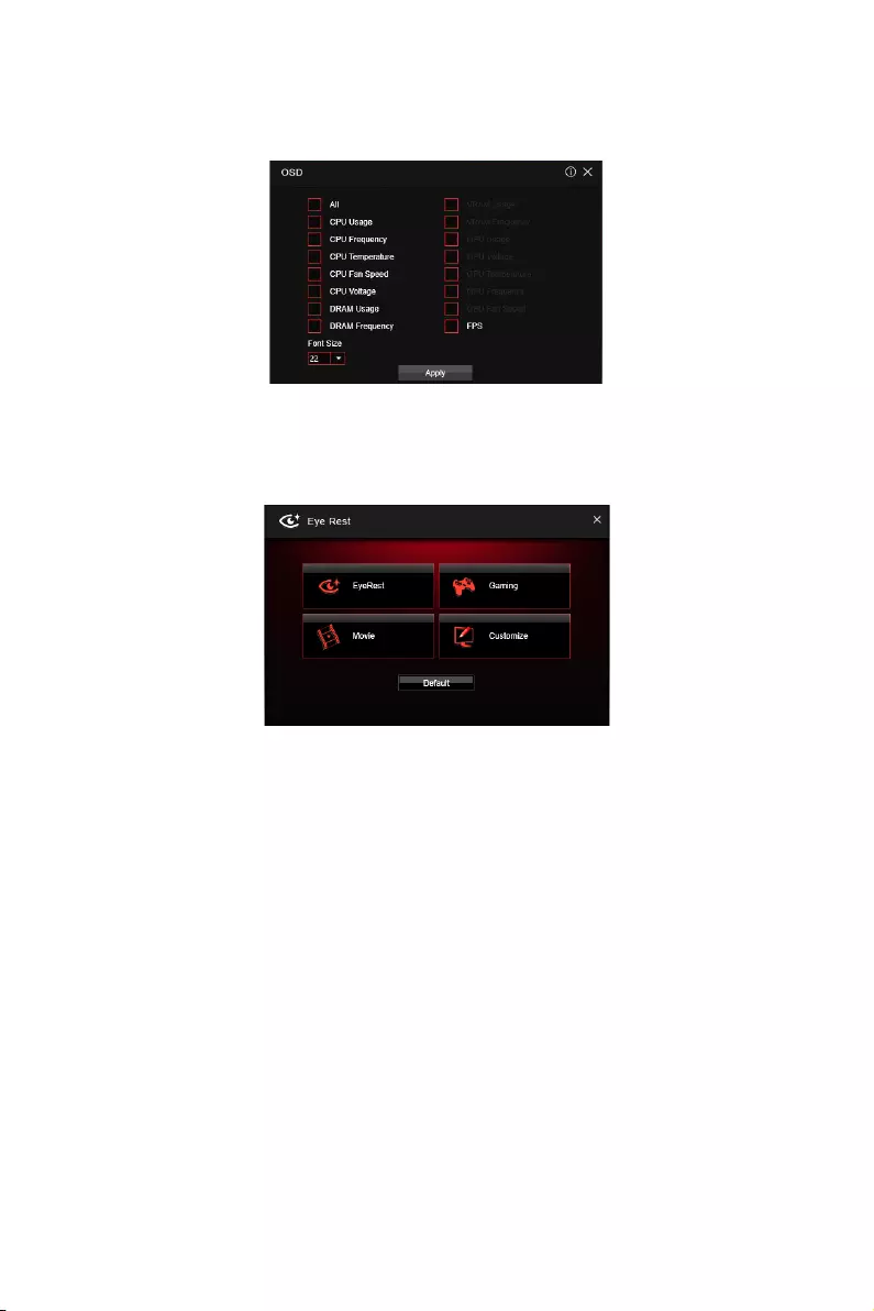
87
Software Description
OSD Setting Panel
Use the OSD setting panel to specify information within on-screen display (OSD).
yApply Button — applies above settings to OSD.
Eye Rest
Eye Rest allows you to optimize the display on your monitor.
yEyeRest — reduces blue-light of your LED backlit screen, in order to protect your
eyes.
yGaming — automatically increase contrast ratio of your screen.
yMovie — automatically increase dynamic contrast ratio of your screen.
yCustomize — allows you to adjust gamma, contrast and color balance for your screen.
yDefault — loads the default settings.

88 Software Description
VR Ready
It will optimize the performance of your system to ensure everything is VR Ready.
Applications
VR ON/ OFF
yVR ON/ OFF -enables or disables VR settings.
yApplications — appears when you turn on the VR support. It allows you to close some
applications to optimize the system for better VR experience.
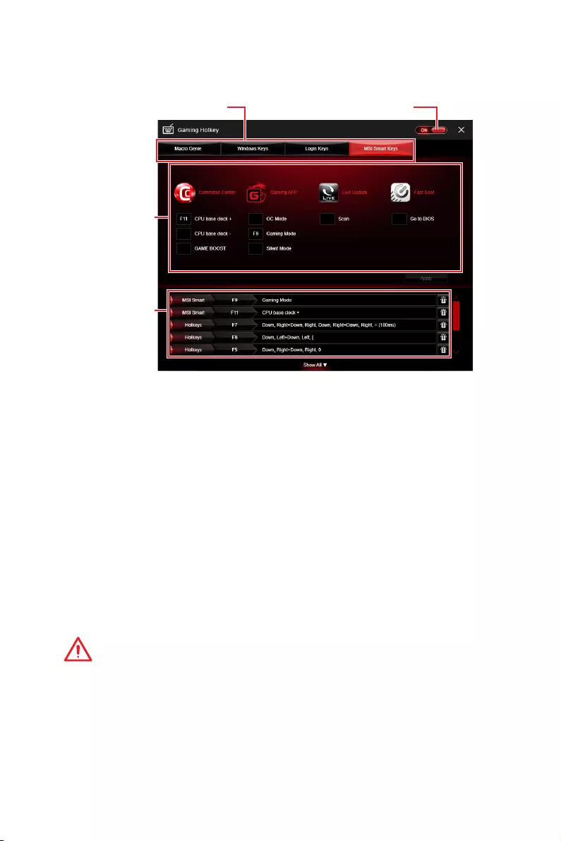
89
Software Description
Gaming Hotkey
Gaming Hotkey provides instant control of the system through user defined hotkeys.
Categories Toggle
Hotkey Manager
Current Hotkeys
Gaming Hotkey ON/OFF
yGaming Hotkey ON/OFF — allows you to turn ON/OFF the Gaming Hotkey function.
yCategories Toggle — allows you to toggle over the Hotkey categories.
Macro Genie — provides the keyboard and mouse macro record function and
allows you to define the hotkeys for the macro recorder.
1. Click on the Record button to start the keyboard and mouse macro recorder.
2. Click on the Stop button to stop the recorder.
3. Key-in a file name and set-up the parameter for the macro.
4. Finally, click on the Save button to save the recorded macro.
Windows Keys — allows you to define hotkeys to replace Windows default
keyboard shortcuts.
Login Keys — provides hotkey login function.
MSI Smart Keys — allows you to define hotkeys for MSI Smart Keys.
yHotkey Manager — allows you to create, edit and delete hotkeys.
yCurrent Hotkeys — shows all existing hotkeys.
Important
y
The Caps Lock, Num Lock, Scroll Lock, Window Home, Application and BackSpace
keys can not be used as Hotkeys.
y
Some key combinations are reserved for use by Microsoft Windows and can not be
assigned as a hotkey.

90 Software Description
Mouse Master
Mouse Master provides mouse macro function. You can also use it to change DPI of
your mouse.
Delay Time
Macro Hot Key DPI Hot Key
Test Area
Clear Button
Mouse Action
DPI Setting
Default Button
Action List
Edit Buttons
Load Button
Save Button
yDelay Time — allows you to apply a delay time in mouse macro.
yMacro Hot Key — allows you to assign a hotkey from A to Z to activate the macro.
yMouse Action — assigns mouse actions to the macro.
New — captures the mouse coordinate and add to the macro.
Left — add a left-click to the macro.
Middle — add a middle-click to the macro.
Left — add a left-click to the macro.
yAction List — shows the actions of the current macro.
yEdit Buttons — there 3 buttons for editing the macro.
Run — activates the macro.
Delete — removes the selected action from the macro.
Clear — removes all actions from the macro.
yLoad Button — allows you to load a macro.
ySave Button — allows you to save the macro to a file.
yDPI Setting — allows you select the mouse DPI from the drop-down menu.
yDefault Button — reverts to the default DPI setting.
yDPI Hot Key — allows you to assign a hotkey from A to Z to activate the DPI setting.
Please note that you muse hold the hotkey to keep the DPI setting. When you release
the hotkey, the DPI setting will be reverted to default.
yTest Area — allows you to test the mouse movement.
yClear Button — clears the test area.
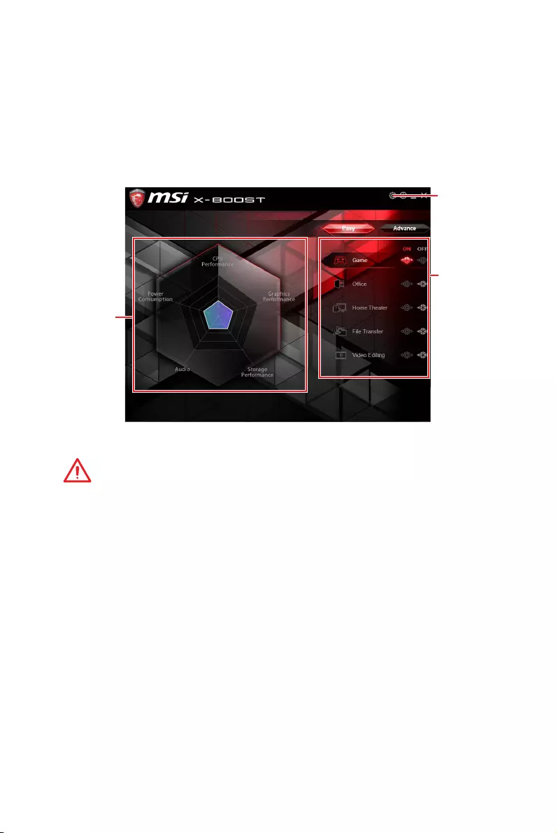
91
Software Description
yPerformance information — displays the system performance diagram of enabled
mode.
ySetting — enables or disables Run X-BOOST when windows starts.
X-BOOST
The MSI X-BOOST allows you to select the system performance mode to meet your
current system environment or support faster storage access speed for your external
storage or memory cards.
Easy
In Easy page, you can select one system performance mode to meet the current
system environment.
Setting
Performance
information
Performance
mode
yPerformance mode — moves over the mouse to any one of performance mode and
click on the ON button to enable it.
Important
The Customize mode is the default of system performance.
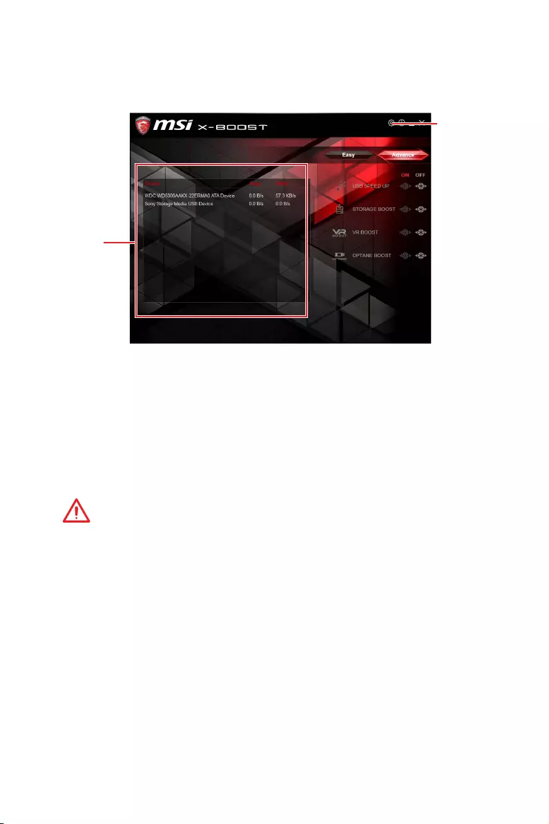
92 Software Description
Advance
In Advance page, you can enable the USB SPEED UP, the STORAGE BOOST and VR
BOOST.
Setting
Device
information
yDevice information — displays the information and current transfer rates/ access
speeds of USB/ storage devices.
ySetting — enables or disables Run X-BOOST when windows starts.
yUSB SPEED UP — supports faster data transfer rates of the USB storage devices.
ySTORAGE BOOST — supports faster access speed of storage device.
yVR BOOST — provides the optimized settings to boost the system for better VR
experience.
yOPTANE BOOST — supports faster access speed of Intel Optane memory (require a
reboot).
Important
y
Please note that you can only select one mode at a time from Easy or Advance page
as MSI X-BOOST function.
y
The improved transfer rate/ access speed will vary with the USB/ storage device.
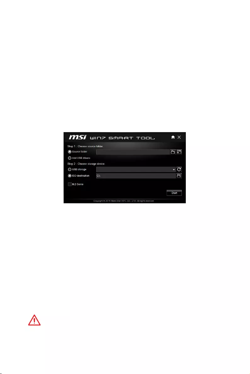
93
Software Description
MSI SMART TOOL
MSI SMART TOOL is a convenient tool that can help you to create your Windows
installation USB flash drive with USB 3.0 drivers, and it can also create a software
RAID.
Main menu
After installing and activating MSI SMART TOOL, it will display a main menu for you
to choose Win7 Smart Tool or Software RAID. Note that the Software RAID is only
available when your system equipped with at least 3 hard-disk drives (1 system disk
and 2 data disks).
WIN7 SMART TOOL
Before you can create your Windows installation USB flash drive, you’ll need to have
your Windows Installation DVD or ISO file, and also have a minimum of a 8GB USB
flash drive to create your installer. Be sure to backup files on the USB drive, this
process will erase it.
To create the Windows installation USB drive:
Step1. Choose source folder
yIn the Source folder box, type the name and path of your Windows ISO file, or
click Browse button and select the file from the dialog box. (This option will copy all
Windows installation files and USB 3.0 drivers)
yIf you already have the Windows Installation USB flash drive and just want to add
USB 3.0 drivers on it, you can choose Add USB drivers.
Step2. Choose Storage device
yChoose USB storage and select your USB flash drive in the drop-down list. In case
the USB flash drive is not listed, click the Refresh Drive button.
yIf you want to install Windows on the PCIe M.2 RAID that was created by BIOS > M.2
Genie (please refer to BIOS Setup Section for details), check the M.2 Genie checkbox
to copy iRST drivers to the USB flash drive.
yClick Start.
Important
You can also create an installer ISO image file by selecting the ISO destination in
Step2, and then burn it onto the DVD. However, this method does not support M.2
Genie.

94 Software Description
SOFTWARE RAID
This utility allows you to create a software RAID in Windows system.
To create a software RAID:
1. Use checkboxs to select the disks you want included in your RAID.
2. Choose Speed Up or Backup for RAID type.
ySpeed Up = RAID0
yBackup = RAID1
3. Click Start.
4. When prompt Finish!, click OK.
Important
Software RAID can’t includ the system disk.
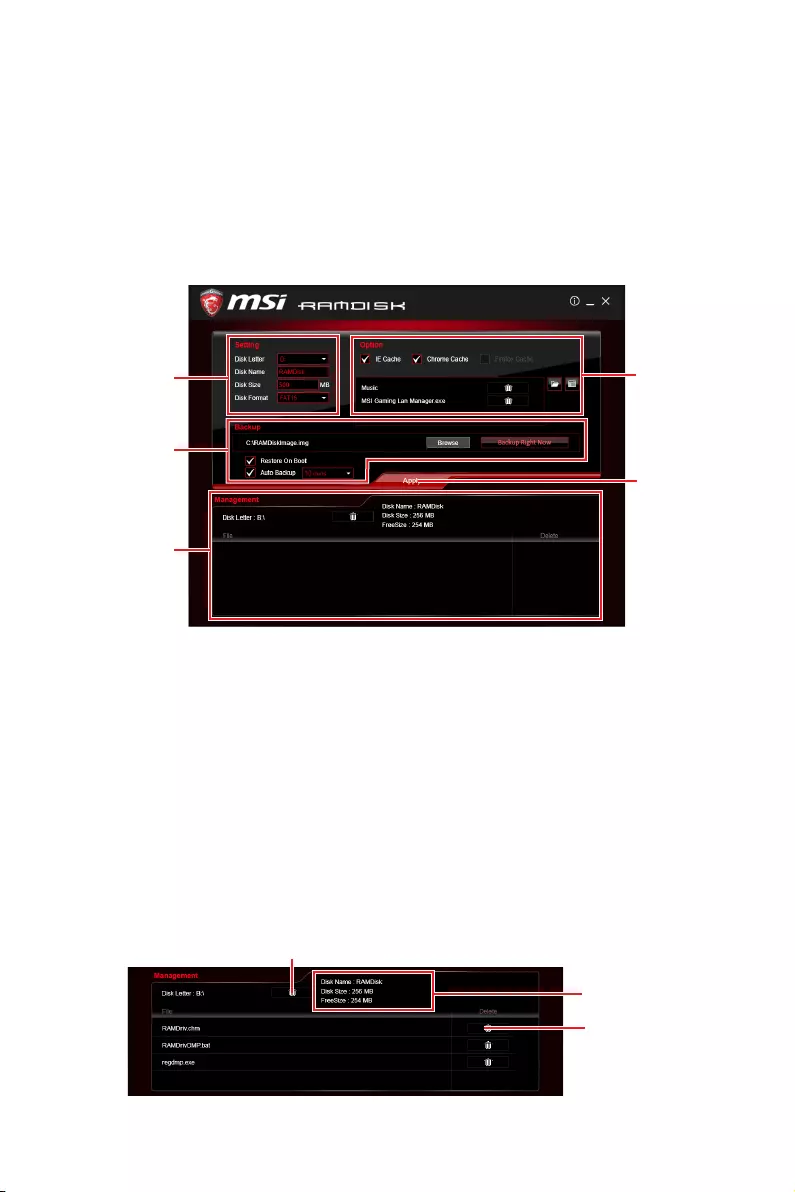
95
Software Description
RAMDISK
RAMDISK creates a virtual RAM drive using the available memory in your computer,
the performance of the RAMDISK is faster than an SSD and hard drive. RAMDISK
allows you to store any temporary information on it. Furthermore, using the RAMDISK
will extend your SSD’s life by sparing it from excessive reading and writing.
Creating a RAM Disk
When RAMDISK is started, it will create a default RAM disk. If you want to change
settings, refer to following instructions.
Setting
Backup
Management
Option
Apply
Button
ySetting — specify Letter, Name, Size and Format of the RAM disk.
yOption — select browser temporary files to save/load on the RAM disk. You can also
add software files to improve reading speed.
yBackup — specify backup and restore settings to prevent data loss. All files will be lost
each time the RAMDISK is stopped if you do not backup.
Browse Button — set the path to the image file.
Backup Right Now Button — manually backup files.
Restore On Boot — check this box to have the image file loaded automatically when
RAMDISK starts.
Auto Backup — check this box to backup automatically over a period of time.
yApply Button — allows you to apply changes.
yManagement — shows RAMDISK information and allows you to delete files.
Dislpay
information
Delete files
in the RAM
disk.
Remove the RAM disk
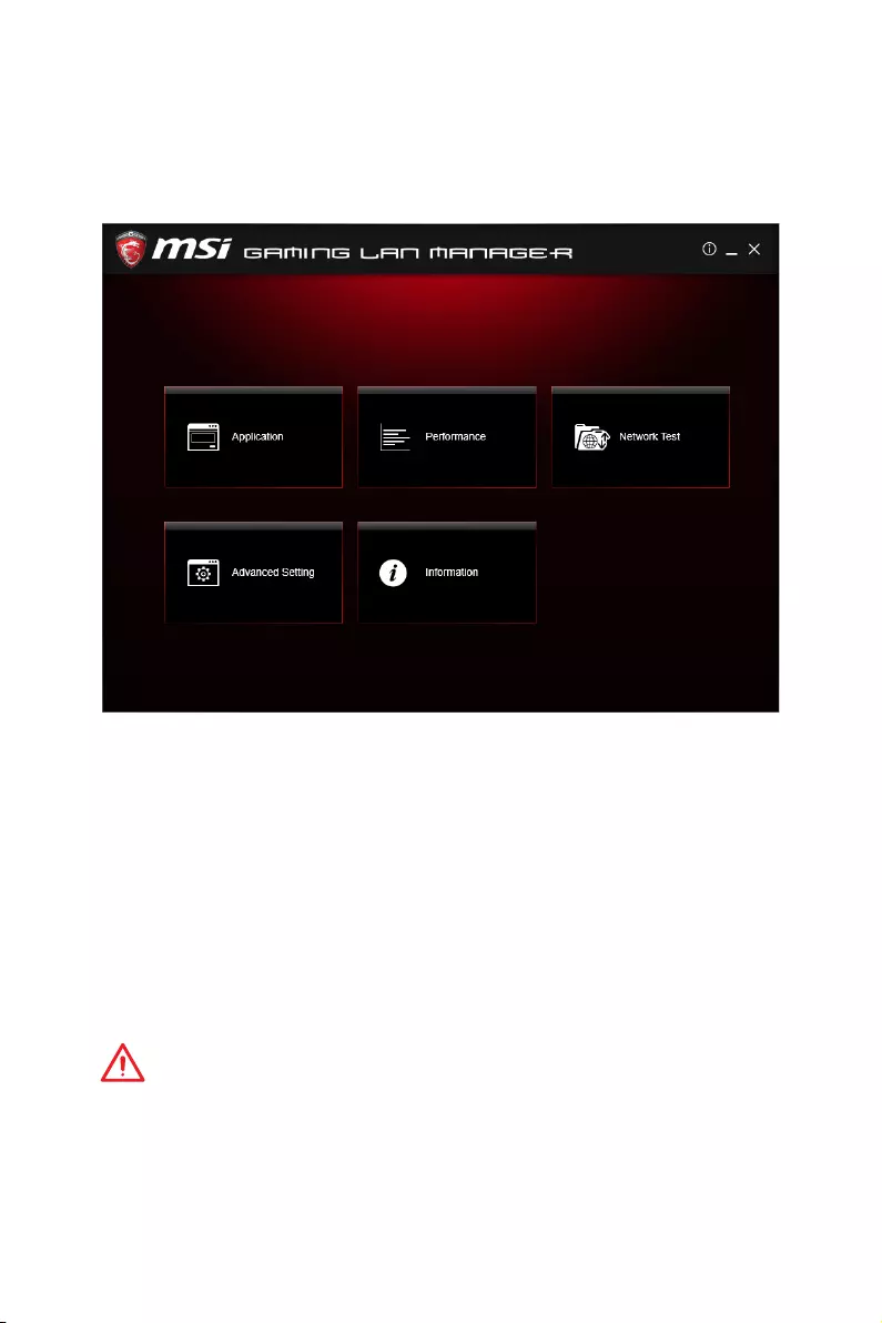
96 Software Description
GAMING LAN MANAGER
GAMING LAN MANAGER is an utility for traffic shaping for the Windows 7/ 8.1/ 10.
It can keep your internet fast during heavy upload/ download and improve your ping
for online games. If your motherboard has a Wi-Fi module, GAMING LAN MANAGER
provides virtual access point function for traffic shaping for your mobile devices.
yApplications — displays currently using network bandwidth applications. You can
prioritize Games, Medias or File sharing programs as high as possible.
yPerformance — shows top 5 applications by total traffic, allows you to monitor
network bandwidth usage.
yNetwork Test — allows you to setup bandwidth control.
yAdvanced Setting — allows you to expand RWIN to accelerate download speed. You
can also block IP address and setup virtual access point.
yInformation — shows version information.
Configuring Bandwidth
This section describes how to configure Internet Provider Speed. You can configure
default internet upload and download bandwidth from the Network Test tab on the
GAMING LAN MANAGER window.
Important
Before using the GAMING LAN MANAGER for the first time, you should use the
Test Network Speed button which runs a speed test of your current total Internet
bandwidth delivered through your Internet service provider.
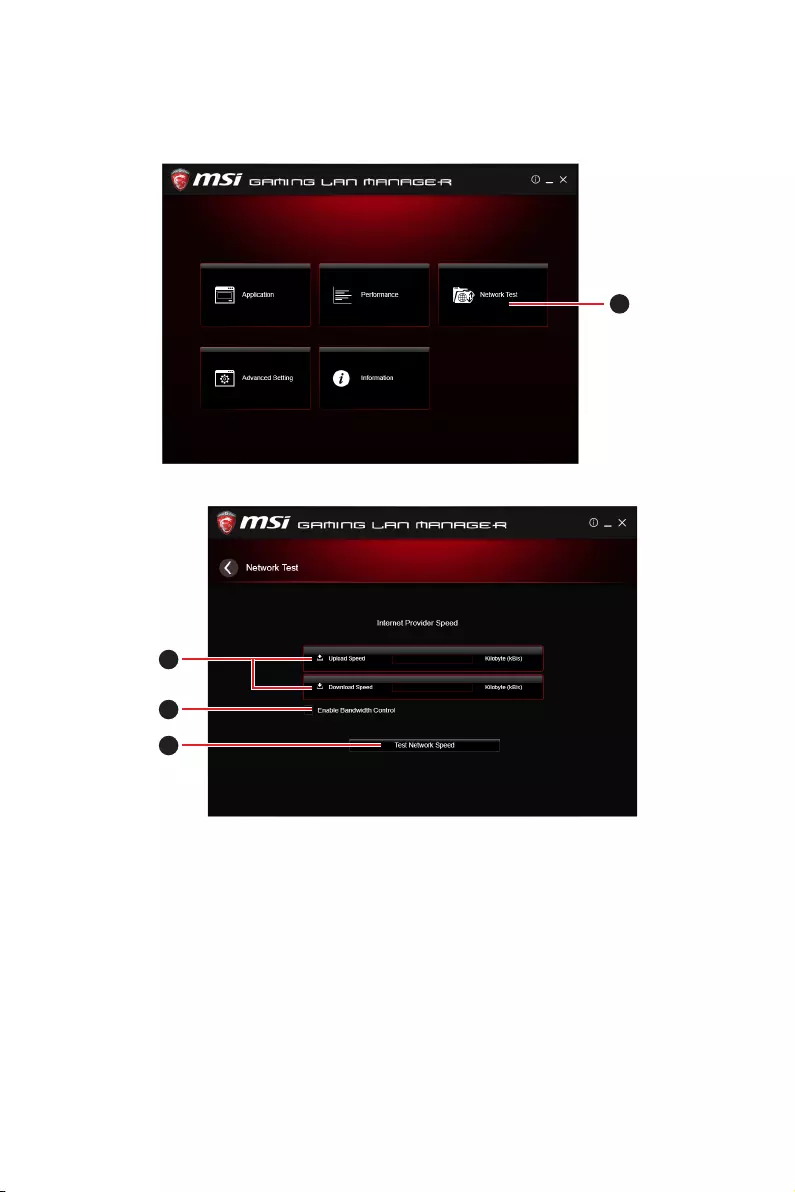
97
Software Description
Speed Testing
The speed testing is used to optimize bandwidth usage. To test the Upload and Down-
load speed, please follow the steps below:
1
1. Click the Network Test block in GAMING LAN MANAGER.
2
3
4
2. Click Test Network Speed button. The test takes several minutes to test your
network speed.
3. Enter the testing results into Upload Speed and Download Speed fields.
4. Check the Enable Bandwidth Control to allow the GAMING LAN MANAGER to
manage the bandwidth.
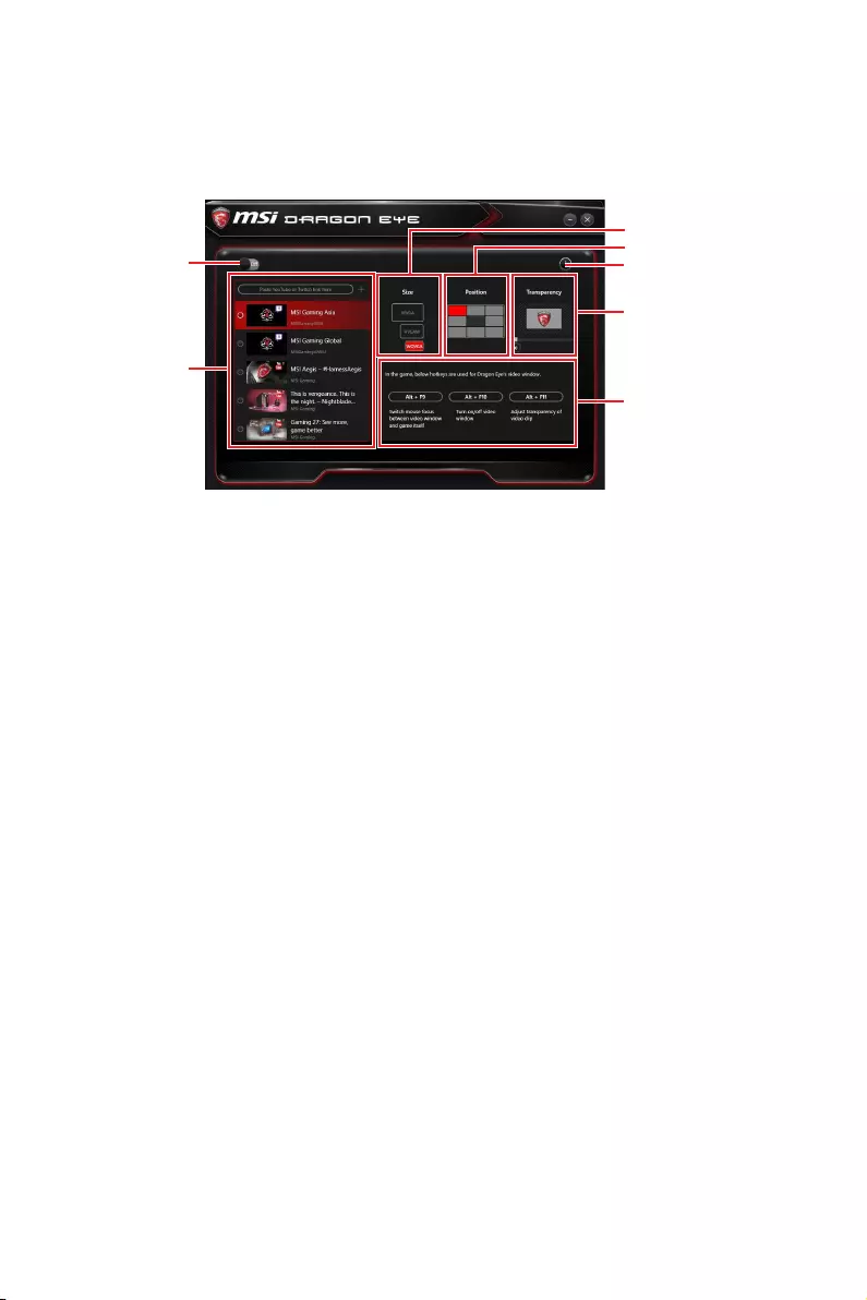
98 Software Description
DRAGON EYE
DRAGON EYE allows you to watch game guides, tutorials, live match or tournament
stream while gaming. In game, you can use hotkeys to control/adjust the settings of
DRAGON EYE.
Help
Size Settings
Position Settings
Transparency Settings
Hotkeys Information
On / Off Switch
Video List
yOn / Off Switch — enables or disables Dragon Eye during your gaming sessions.
Switch it on before you launch the game in order to watch video while playing.
yVideo List — contains the videos you can select to watch. You can add videos or
streams to the list by pasting their URL into the input bar and hit+.
ySize Settings — allows you to select the size of the Dragon Eye video content
displayed on-screen when you’re playing a game. There are three options available:
WQVGA (Small – 400×240)
HVGAW (Medium – 640×360)
WVGA (Large – 768×480)
yPosition Settings — allows you to determine how you want to position your DRAGON
EYE windows on screen to avoid interfering your gaming experience.
yHelp — If you want to watch the video tutorial for Dragon Eye or want to see if your
game is supported, press this button and the help window will be shown.
yTransparency Settings — allows you to set the transparency of your Dragon Eye video.
0 = opaque | 100 = transparent.
yHotkeys Information — In this information section you can find the hotkeys for Dragon
Eye. There are three hotkeys:
Alt+F9 — switches mouse focus between video window and game itself. (Direct
interface to adjust progress bar, volume and other settings of video during the
game)
Alt+F10 — turns on/off video window .
Alt+F11 — adjusts transparency of video clip.
NOTE: To customize hotkey, simply select the hotkey icon and then press the keys
combination you want to use as a hotkey.
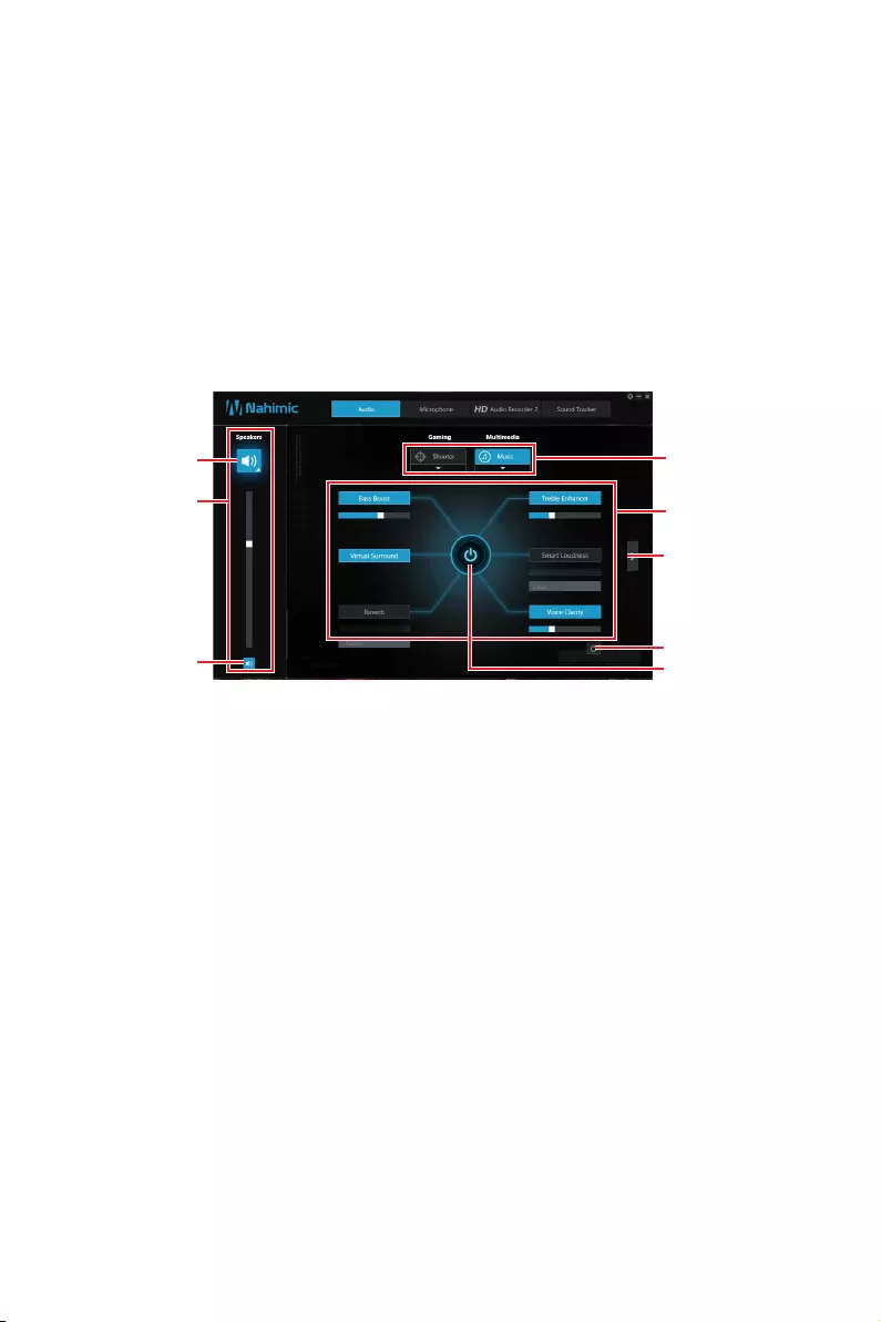
99
Software Description
Nahimic 2
Nahimic 2 is designed to offer the best audio experience it contains 6 audio effects, 3
microphone effects, HD Audio Recorder2 and Sound Tracker.
Installation and Update
Nahimic 2 is included in the audio driver. If you need to install it or update it, please
use the Driver Disc with your motherboard or download the driver from MSI’s official
website.
Audio Tab
From this tab, you can access all of Nahimic 2’s audio effects, audio profiles and
settings.
Profiles
Audio Effects
Reset Button
EQ Profile
Page
On/Off Button
Display &
Volume
Mute
Device
properties
yDisplay & Volume — displays the type of audio rendering device currently being used
as output, as well as its current volume.
Mute — mutes the current audio output device.
Device properties — allows you to change the format, sample rate, bit rate and
the channel gain of the current device (if these options are available for the current
device). Clicks on this button and a device properties panel will show.
yProfiles — allows you to adjust the 6 audio effects to your current listening
experience.
Gaming — allows you to choose an audio profile to fit your gaming experience.
Multimedia — allows you to choose an audio profile to fit your everyday experience.
yAudio Effects — allows you to separately control any of the 6 audio effects.
Bass Boost — increases the energy in low frequencies up to +12 dB.
Virtual Surround
Gaming and Movies — virtualizes the multichannel audio stream and downmixes
it in order to retrieve a multichannel listening experience over your stereo
headphones or speakers.
Music — expands the stereo for a wider sound stage.
Reverb — increases the feeling of space by applying different types of reverbs
corresponding to different room sizes.
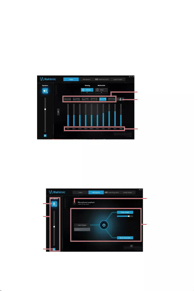
100 Software Description
Treble Enhancer — Increases the energy in high frequencies up to +12 dB.
Smart Loudness — maintains a constant volume for all elements of the audio
experience to making them all sound softer, balanced or louder.
Voice Clarity — boosts the speech in movies, video games and incoming
communication from +0 through +12 dB (0 to 100%).
yReset Button — restores the current profile to its default values.
yOn/Off Button — allows you to turn on and off all Nahimic 2’s effects in one click.
yEQ Profile Page — by clicking the arrow button, you can also access a second page
that contains the x10 bands EQ and EQ profiles.
EQ Profiles
Custom EQ
Profile
x10 bands EQ
EQ Profiles — allows you to choose between 6 EQ profiles to fit your audio
experience
Custom EQ Profile — you can change the x10 bands of the Custom EQ profile so as
to make it fit your current needs.
x10 bands EQ — x10 bands EQ, from 32Hz to 16KHz.
Microphone Tab
From this tab, you can access all of Nahimic 2’s microphone effects and settings.
Microphone
Loopback
Microphone
Effects
Display &
Volume
Mute
Device
properties
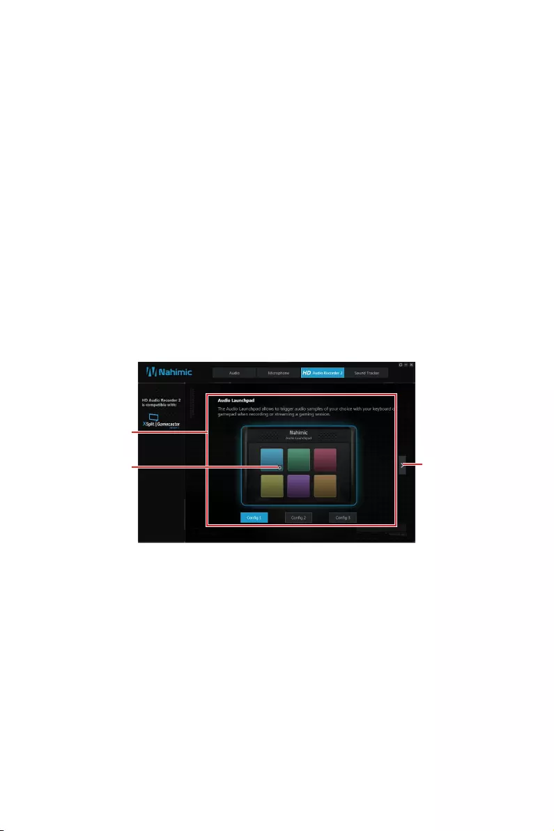
101
Software Description
yDisplay & Volume — displays the type of audio recording device currently being used
as input, as well as its current volume.
Mute — mutes the current device.
Device properties — allows you to boost the volume and modify the left/ right
balance of microphone. Clicks on this button and a device properties panel will
show.
yMicrophone Loopback — turns the microphone loopback On/Off. In order to avoid any
feedback (Larsen effect).
yMicrophone Effects — allows you to separately control any of the 3 microphone
effects.
Voice Shaper — applies a filter to the voice.
Voice Leveler — levels the volume of your voice in order to avoid any saturation
and maintains a constant and clear communication. Voice Leveler can be adjusted
with a 0 to 100% slider.
Noise Reduction — removes the remaining sound that the Noise Gate has left on
top of your words and sentences.
HD Audio Recorder 2
From this tab, you can access the audio launchpad and HD Audio Recorder 2 settings.
Audio
Launchpad
effects Control page
Pad
Properties
yAudio Launchpad effects — allows streamers to use prerecorded sounds during a
livestream. These sounds can also be heard by viewers. This tool will allow you to
create your true audio identity. That way, your livestreams will be more personal and
animated. The Audio Launchpad is one of the fresh new features of Nahimic 2. As it’s
a feature designed for broadcasters, we included it in the HD Audio Recorder 2 page.
Pad Properties — every pad can be customized by clicking the properties button
that will appear in its bottom right when hovering over it with your mouse.
On the Pad Properties panel you can choose:
The sound assigned to each pad.
The keyboard hotkey assigned to each pad.
The color assigned to each pad.
Config 1, 2 & 3 — allows you to prepare 3 completely different configurations so as
to adapt the Launchpad to the content you are streaming. Each configuration has 6
customizable pads. The 3 configurations are independent, meaning Config 1 cannot
be used at the same time than Config 3.

102 Software Description
yControl Page — by clicking the arrow button, you can access the control page.
Audio Launchpad ON/OFF — switches the Audio Launchpad on or off.
HD Audio Recorder 2 — The HD Audio Recorder 2 is, by default, automatically
launched when a XSplit Gamecaster 2 recording session is detected. The launch of
the HD Audio Recorder 2 enables HD audio processing over an XSplit Gamecaster
2 recording without any need for adjustments. The HD Audio Recorder supports
XSplit Gamecaster 2.
Pop-up message ON/OFF — switches the pop-up message on or off.
Sound Tracker
The Sound Tracker is an FPS oriented feature that provides a visual indication
localizing the source of the strongest sound while in a game. The Sound Tracker
captions the 5.1 and 7.1 sound streams processed by your audio system, and is
displayed in all applications and games using DirectX 9, 9c, 10 and 11. Please
remember Sound Tracker is only available if you are using an audio device that
supports Nahimic 2 effects.
Sound Tracker
Effects
ON / OFF button and hotkey — switches the Sound Tracker on or off.
Hotkey — use the CTRL + SHIFT + S to turn ON / OFF the Sound Tracker.
7.1 Audio Test — launch a 7.1 audio sample allowing you to preview how the radar
will react in your game.
Transparency — allows you to adjust the transparency of the Sound Tracker,
making it look more or less discrete.
Scale — allows you to adjust the scale of the Sound Tracker, making it look bigger
or smaller.
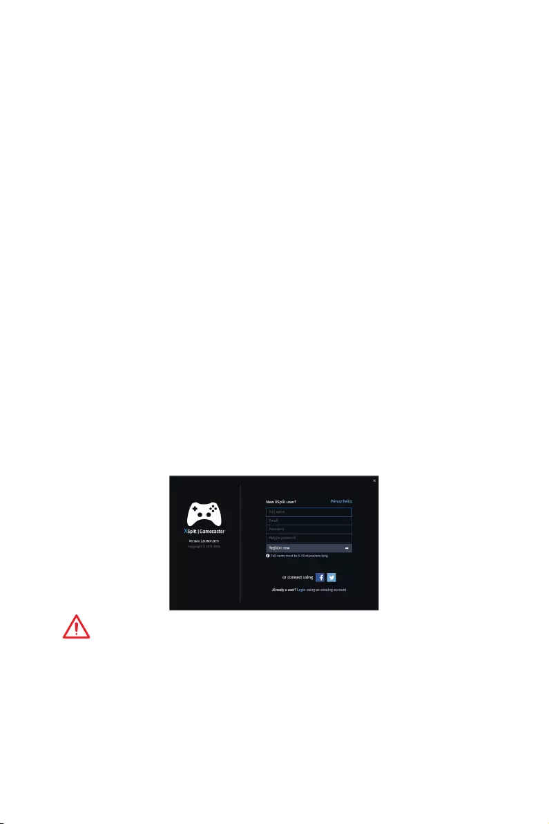
103
Software Description
XSplit Gamecaster V2
XSplit Gamecaster is the newest product from SplitmediaLabs, the creators of XSplit
Broadcaster, the world’s most popular streaming application.
XSplit Gamecaster was designed to provide gamers with the simplest and most
uncomplicated way to create high quality gameplay recordings and live streams. By
utilizing the revolutionary in-game overlay, streamlined encoding, and social network
features, you’ll be sharing your gameplay to your family, friends, and followers in no
time!
System Requirement
yHardware specifications:
For HD 720p Recording/Streaming — Core i5 CPU or equivalent
For HD 1080p Recording/Streaming — Core i7 CPU or equivalent
4 GB RAM minimum
8 GB free hard disk space
GeForce/Radeon Class Graphics card, minimum Direct X hardware level 10.1
ySoftware specifications:
Windows® 7 SP1 32bit/ 64bit, Windows® 8.1 32bit/ 64bit
.NET Framework 3.5
DirectX 10.1 or better
Logging
After installing and activating XSplit Gamecaster V2, it will display a login dialogue. If
you already have an account and password, fill your email and password into the form
and click the Login button.
Important
When starting XSplit Gamecaster V2 on select MSI
®
gaming laptops, all-in ones or on
machines that contain select MSI
®
motherboards or graphics cards, you will receive
a free 6 month XSplit premium license that you can apply to an existing free account
or to a new account. If you already have an XSplit account with a personal or premium
license, then you can instead add 6 months to your license duration.
Registering an Account
If you don’t have an XSplit account yet, click Register now on the login dialogue. When
the user registration form appears, complete all the fields.
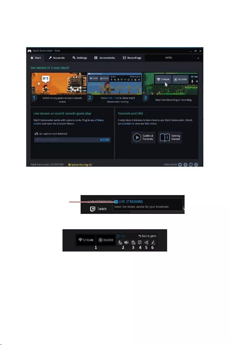
104 Software Description
Learning stream and record
Refer to the Start page of XSplit Gamecaster V2 to learn how to stream and record your
gameplay.
Tool Tip
When you click the question mark next to a feature name on the panel, a tooltip will
show, describing the particular function of that item.
Question mark
Inside the XSplit Gamecaster Overlay
1. Streaming/Recording Buttons — Press Stream to start live streaming or Record to
start recording.
2. Microphone/System Sound Control — Pressing the microphone or system sound
button will enable or disable the microphone or system sound.
3. Webcam Controls — To enable webcam controls, you must first select a camera/
webcam in the Settings Tab. Once you have selected a webcam, you can activate it
by clicking on its icon in the XSplit Gamecaster V2 overlay.
4. Twitch Chat Controls — If you’ve signed in to your Twitch.tv account, you’ll see a
Twitch icon in the overlay. When you click on this icon, a window will open. This
window is XSplit Gamecaster’s integrated chat system.
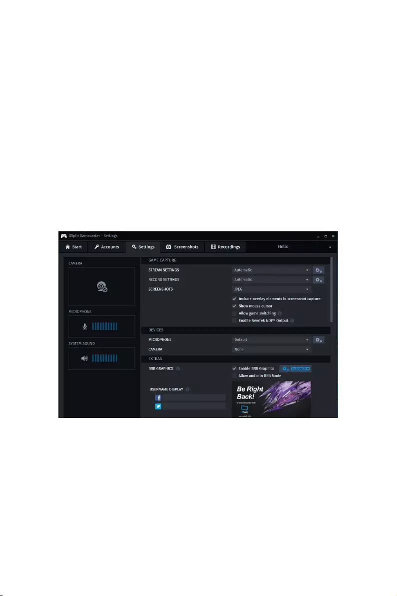
105
Software Description
5. Share Button — If you authorize your Facebook, Twitter, and/or Google+ accounts,
you can quickly share your stream URL and status update within the overlay.
6. Annotations — This feature of XSplit Gamecaster V2 allows you to draw directly
onto your game play. You can activate annotation mode by clicking on the pencil
button in the overlay.
Accounts Tab
yLive Streaming — allows you to stream to a variety of live streaming services such as
YouTube, Twitch, Ustream, Dailymotion, Niconico and also allows for custom RTMP
streaming.
yVideo Sharing — allows you to directly upload recordings to YouTube from within the
software.
ySocial Network — allows you to share your live stream or YouTube links to friends &
followers on Google+, Facebook, and Twitter. To allow XSplit Gamecaster to post on
your desired social network, click on the Authorize To Post On… button of your desired
social network and enter your username and password to authorize.
Settings Tab
yStream Settings — The default setting is Automatic mode. In Automatic mode, your
stream settings are automatically determined by XSplit Gamecaster based on your
computer and internet resources (this includes resolution, bitrate, codec, but frame is
always set to 30). You can change to a different resolution by clicking on the drop-down
arrow.
yRecord Settings — The default setting for recording is Original Resolution. This
refers to the resolution of the game that’s been set inside the game’s video/graphics
settings. You can change to a different resolution by clicking on the drop-down arrow.
yMicrophone Settings — In this region, you can select your desired microphone. What
is shown in the list depends on what you have connected to your PC. If you don’t

106 Software Description
see your desired device in the list, please make sure that it is detected and it is not
disabled in your recording devices list in the Windows® Sound Menu (Start > Control
Panel > Sound > Recording).
yCamera Settings — In this region, you can select your desired camera. What is shown
in the list depends on the cameras you have connected to your PC (Control Panel >
Device Manager > Imaging Devices).
yBRB Graphics (Be-Right-Back Graphics) — BRB Graphics are activated when you
alt-tab or minimize your game. BRB Graphics will not work in Console Viewer mode.
You can enter the BRB Graphics editor by clicking on the gear icon next to the BRB
Graphics preview.
Recordings Tab
yArranging Recordings — In the Recordings Tab, you can view your recordings as
thumbnails or in a listed format by clicking on the button in the top right corner
of the window. You can sort your recordings by name, date, length, and size by right
clicking in the Recordings Tab.
yOpening Recordings Folder — To open your recordings folder in Windows® Explorer,
click on Open Folder.
yChanging Recordings Location — To change the location of where your videos will be
saved, click on the recordings folder location.
yUploading video recordings to YouTube — To upload to YouTube, you must first
authorize your account in the Accounts Tab. After you have authorized your account,
click on a recording and then click on the YouTube logo in the bottom right corner. A
window will open and you will be able to fill out the title, description, category, tags,
privacy, and you will be able to choose to allow or disallow embedding. Once you have
entered the details for YouTube, press the Upload Now button.
ySharing on Social Media — Once a video has been uploaded, you can share the
YouTube link on any social media accounts you have connected to XSplit Gamecaster.
Simply click on the icon of the social media site you wish to share, and a window will
appear where you can enter some details about your post before publishing your link.
When you are done entering the details of your post, click Share Video to post it to your
selected social media account.
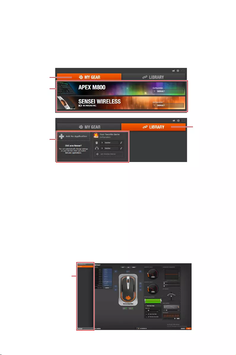
107
Software Description
SteelSeries Engine 3
SteelSeries Engine 3 is a unified platform built to support all of SteelSeries products.
It can deploy your saved device settings automatically when switching between your
favorite games or applications.
After installation the SteelSeries Engine background processes will start and the
interface will open automatically.
My Gear
Library
Device Cards
Application
Configuration
yMy Gear — all of your SteelSeries devices in one place.
Device Cards — all of your SteelSeries devices are easily accessible from the My
Gear tab, regardless of type, connection status, or which applications they are
assigned to.
yLibrary — quickly set up your configurations to autolaunch with an application.
Application Configuration — you can choose to have configurations deploy
automatically whenever you use a specific game or application. Add any number
of applications to your library and SteelSeries Engine 3 will seamlessly change the
configurations of your devices as you switch between them.
Configuration Windows
Configuration Windows are unique to their devices and each of them includes a
collapsible Configuration List Panel of all the configurations for that device. You
can create a new configuration by selecting the New button at the bottom of the
Configuration List Panel.
Configuration
Windows
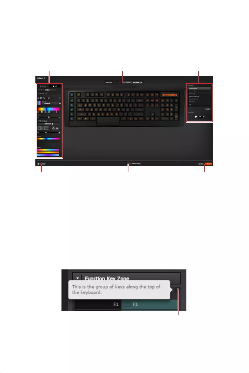
108 Software Description
Configuring Your Devices
You can custom configurations for SteelSeries devices in their Configuration Windows.
The top left displays the name of the configuration you are viewing, the body features
widgets for customizing various functions of the device, and at the bottom are Save/
Revert buttons, a Live Preview toggle, and a button to open/close the collapsible
Configuration List Panel.
Configuration Windows Toggle
Widgets ToggleWidgets Widgets
Live Preview Revert/ Save Button
yWidgets — allow you to customize a certain aspect of your device.
yWidgets Toggle — allows you to toggle Widgets .
yConfiguration Windows Toggle — allows you to toggle the Configuration Windows.
yLive Preview — gives you the full experience of your configuration’s look, feel, and
sound while you are editing it.
yRevert/ Save Button — configuration changes are not written to the database until
you select Save. This gives you freedom to experiment, knowing that you can select
Revert to undo changes.
Tool Tip
When you click the question mark next to a feature name on the panel, a tooltip will
show, describing the particular function of that item.
Question Mark
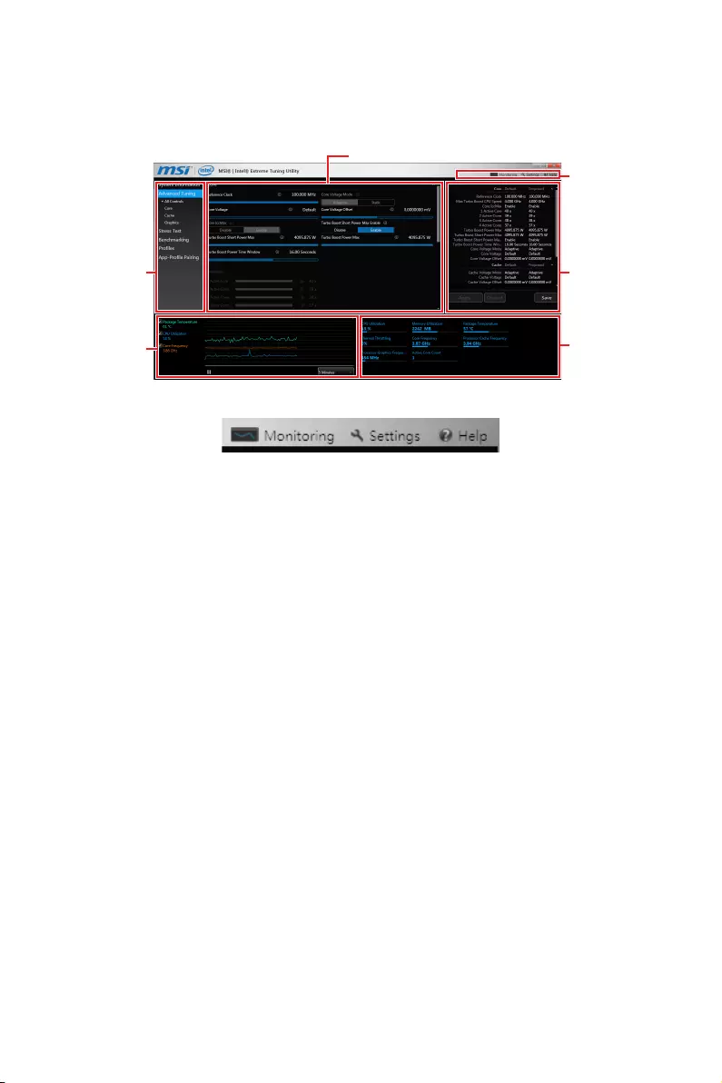
109
Software Description
Intel® Extreme Tuning Utility
Intel® Extreme Tuning Utility (Intel XTU) is a simple overclocking software for you to
tune, test and monitor your system.
Navigation
Views
Settings
Help
System
Table
System
Monitors
System
Graphs
Tuning Controls
yViews Settings Help
Views — toggles to switche between Monitoring and Show All view.
Settings — opens the General Settings window.
Help — displays the help content for Intel XTU in a separate window.
yNavigation — lists all of the major functions of Intel XTU.
System Information — shows the details about your system.
App-Profile Pairing — tunes automatically based on active application.
Manual Tuning — changes system settings in a free form.
Stress Test — tests the stability of your system.
Benchmarking — analyzes and compares your system’s performance against
other system profiles.
Profiles — manages sets of system settings.
yTuning Controls — displays the controls for changing the system settings in manual
tuning. For stress tests and profiles, this area displays the settings for these features.
ySystem Table — displays information about the current system settings and a
summary of your changes.
ySystem Graphs — shows measured system values over a period of time. The system
graphs update live as changes are detected in the system. You can customize the
system graphs to show the data you need for your overclocking strategy in the system
graphs preferences.
ySystem Monitors — shows the range of the value, averages, and the current value.
The monitors change color if the monitored values fall into warning or critical zones.
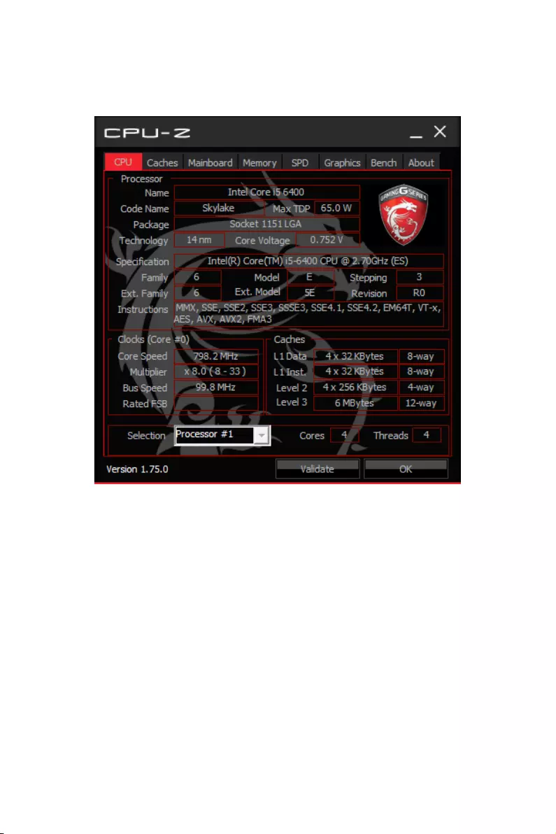
110 Software Description
CPU-Z
CPU-Z is an utility that gathers information on some of the main devices of your
system.
yCPU Tab — shows processor name, code name, package, specification, instructions
sets, core speed and cache levels.
yCaches Tab — shows extended information related to the cache capabilities.
yMainboard Tab — shows motherboard manufacturer, model name, chipset, BIOS
version and graphic interface.
yMemory Tab — shows memory type, memory size, channels, memory frequency.
ySPD Tab — shows specifications relating to each memory module connected to the
motherboard, including the size, type and frequency.
yGraphics Tab — shows GPU name, code name, core speed, memory size, and memory
type.
yBench Tab — allows you to run either a benchmark or a stress test on your processor.
yAbout Tab — shows the CPU-Z version, Windows version, DirectX version and allows
you to save the report file.
111
Software Description
TriDef VR
With TriDef VR you can play your favorite PC games on a huge 3D screen inside your
virtual reality headset. It is compatible with the Oculus Rift and HTC Vive.
After installation, please ensure that your VR headset is set up and working correctly,
then double-click TriDef VR Games on the Desktop, or from:
Start > TriDef > TriDef VR Games
You can now put on your VR headset to experience TriDef VR!
VR Environment
With the headset on, you’ll now find yourself inside a VR environment. Move your head
around to change your view of the surroundings. A virtual screen will be visible in front
of you. This screen will initially be showing the Windows desktop.
While TriDef VR is running, any Windows application you use will be shown on the
virtual screen. Web browsers, games, media players, Windows Store apps, productivity
apps, etc, can all be displayed on this 2D screen.
Use your mouse and keyboard as usual to control the applications. Audio will also be
sent to your headphones.
Main Window
The main TriDef VR application window controls various aspects of the VR experience.
This window can be minimized if desired, but closing the window will exit TriDef VR.
The Help menu provides a link to this user guide, our privacy policy and an about box.
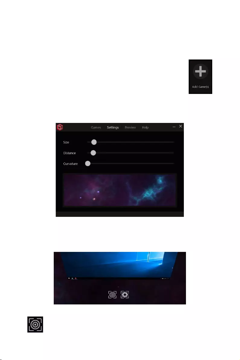
112 Software Description
Games Tab
The first tab you’ll see on the main window is the Games tab. As mentioned, apps or
games launched from the desktop will appear in 2D on the virtual screen. However, if
you launch a supported game from the Games tab, it will be displayed on the virtual
screen in stereoscopic 3D!
The first time you launch TriDef VR, the application will scan your PC and
automatically add supported games to the list. If a particular game wasn’t
found, or new games have been installed, then click the Add Game(s) tile:
Games can be removed from the list by right-clicking on the tile and
selecting Remove. The Edit option in the right-click menu allows you to
modify the game name and other properties.
Settings Tab
The virtual screen’s size, distance, curvature and background environment can be
modified in the Settings tab.
VR Controls
While in the VR environment, look down below the screen to see the Recenter and
Settings items. As you look directly towards those items, a small white dot will appear.
Aim this dot directly at an item to highlight it.
Recenter
Look at the Recenter item for 1 second to enter recentering mode. Now look
in the direction you would like the screen to appear. After a few seconds the
screen will move to the new location.

113
Software Description
Settings Popup
Look at the Settings item for 1 second to display the Settings popup. This
popup window appears in front of the virtual screen. Use your mouse to adjust
the slider values.
yScreen Settings — adjust the virtual screen’s size, distance and curvature.
yGame Settings — adjust 3D settings for that game. Please note that these settings
are not available for applications and games launched from the desktop as those are
displayed in 2D only.
yAdvanced Settings — adjust the audio volume, game FPS and output quality. The
Audio setting is only available when TriDef VR is redirecting the audio from a different
output, so if the slider is disabled, then use the normal Windows volume controls
instead. The Game FPS setting is provided for troubleshooting purposes only. The
Default value should produce the best results. However, if a game appears to be
stuttering on the virtual screen, then other options may fix this. Output quality
determines how TriDef VR displays images on the virtual screen. The Best quality
setting produces smoother images with more readable text characters. This is
achieved by supersampling, which requires additional GPU resources. The Better
option reduces the size of the supersampling process while Good renders the image
without using supersampling.

114 Software Description
TriDef SmartCam
Use TriDef SmartCam to replace or SmartBlur your background in video chat
applications or to remove your background in XSplit.
Just select TriDef SmartCam wherever you see a list of cameras or choose your
webcam application. The following description uses XSplit Gamecaster for an example.
TriDef SmartCam for XSplit Gamecaster
After installation TriDef SmartCam is integrated into XSplit Gamecaster version 2.5
and newer.
To enable TriDef SmartCam, launch Gamecaster as usual, and select the Settings tab.
Click the BACKGROUND option below the camera preview, then select TriDef
SmartCam from the list.
You’ll now see yourself in front of a black background. When you switch to your game,
the black area will be transparent, so the game itself will be visible instead of your
background!
Options
When TriDef SmartCam is selected, several advanced
settings are also made available.
TriDef SmartCam’s background replacement can operate in
one of two modes. In Normal mode, SmartCam will detect
you and any movement in the background. Other people
moving in the background will be included, as will your
arms and other objects that are in motion. This may not
be desirable in some circumstances, particularly in public
settings.
For those occasions, Head & Shoulders Only mode would be more suitable. In this
mode only you will be visible, specifically your face and upper torso. Arms usually wont
be visible in this mode, and neither will objects or people behind you. Tick the Head &
Shoulders Only checkbox to select this mode.
The Quality setting allows you to trade off image quality for processing speed. A higher
quality setting will result in more accurate foreground detection, but requires more
processing. This results in higher CPU usage which can reduce your game’s frame
rate.
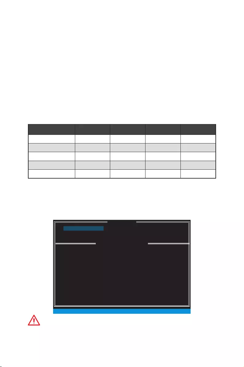
115
RAID Configuration
RAID Configuration
Below are the different types of a RAID.
RAID 0 breaks the data into blocks which are written to separate hard drives.
Spreading the hard drive I/O load across independent channels greatly
improves I/O performance.
RAID 1 provides data redundancy by mirroring data between the hard drives and
provides enhanced read performance.
RAID 5 provides data striping at the byte level and also stripe error correction
information. This results in excellent performance and good fault tolerance.
RAID 10 uses four hard drives to create a combination of RAID 0 and 1 by forming a
RAID 0 array from two RAID 1 arrays.
RAID level comparison
RAID 0 RAID 1 RAID 5 RAID 10
Minimum # drives 2 2 3 4
Data protection None Excellent Excellent Excellent
Read performance Excellent OK Good OK
Write performance Excellent Good OK Good
Capacity utilization 100% 50% 67%~(1-1/n) 50%
Using Intel® Rapid Storage Technology Option ROM
First, you need to set the SATA mode to RAID in BIOS to create, delete and reset RAID
volumes. To enter the IRST Option ROM, reboot and press Ctrl + I keys to enter the
IRST Option ROM during the POST, the following window will appear.
MAIN MENU
[ ]
DISK / VOLUME INFORMATION
[ ]
4. Recovery Volume Options
5. Acceleration Options
6. Exit
RAID Volumes :
None dened.
Physical Devices :
Port Device Model Serial # Size Type/Status (Vol ID)
1 XXXX-XXXXXXXX XXXXXXXXXXXXXX XXX.XGB Non-RAID Disk
2 XXXX-XXXXXXXX XXXXXXXXXXXXXX XXX.XGB Non-RAID Disk
[ ↑↓] — Select [ESC] — Exit [ENTER] — Select Menu
1. Create RAID Volume
2. Delete RAID Volume
3. Reset Disks to Non-RAID
[ ]
MAIN MENU
Important
The following procedure is only available with a newly-built system or if you are
reinstalling your OS. It should not be used to migrate an existing system to RAID.

116 RAID Configuration
Creating s RAID Volume
1. Select option Create RAID Volume and press Enter key. The following screen
appears.
[ ]
CREATE VOLUME MENU
[ ]
HELP
Name :
RAID 1 : Mirrors data (redundancy) .
[ ↑↓] — Change [TAB] — Next [ESC] — Previous Menu [ENTER] — Select
RAID Level :
Disks :
Strip Size :
Capacity :
Sync :
Volume0
RAID1(Mirror)
Select Disks
N / A
XXX.X GB
N / A
Create Volume
2. Specify a RAID Volume name and then press the Tab or Enter key to go to the next
field
3. Use the ↑↓←→ arrow keys to select the RAID level best suited to your usage
model in RAID Level.
4. In the Disk field, press Enter key and use Space key to select the disks you want to
create for the RAID volume, then click Enter key to finish selection. This field will
become available according to the selected RAID level.
5. Select the strip size for the RAID array by using the ↑ upper arrow or ↓ down
arrow keys to scroll through the available values, and pressing the Enter key
to select and advance to the next field. The available values range from 4KB to
128 KB in power of 2 increments. The strip size should be chosen based on the
planned drive usage. Here are some typical values:
RAID0 -128KB / RAID10 — 64KB / RAID5 — 64KB.
6. Select the capacity of the volume in the Capacity field. The default value is the
maximum volume capacity of the selected disks.
Important
Since you want to create two volumes, this default size (maximum) needs to be
reduced. Type in a new size for the first volume. As an example: if you want the first
volume to span the first half of the two disks, re-type the size to be half of what is
shown by default. The second volume, when created, will automatically span the
remainder of two hard drives.
7. Go to the Create Volume field and press Enter, a WARNING message will appear
for you to confirm if you are sure to create the RAID volume. Press Y to continue.
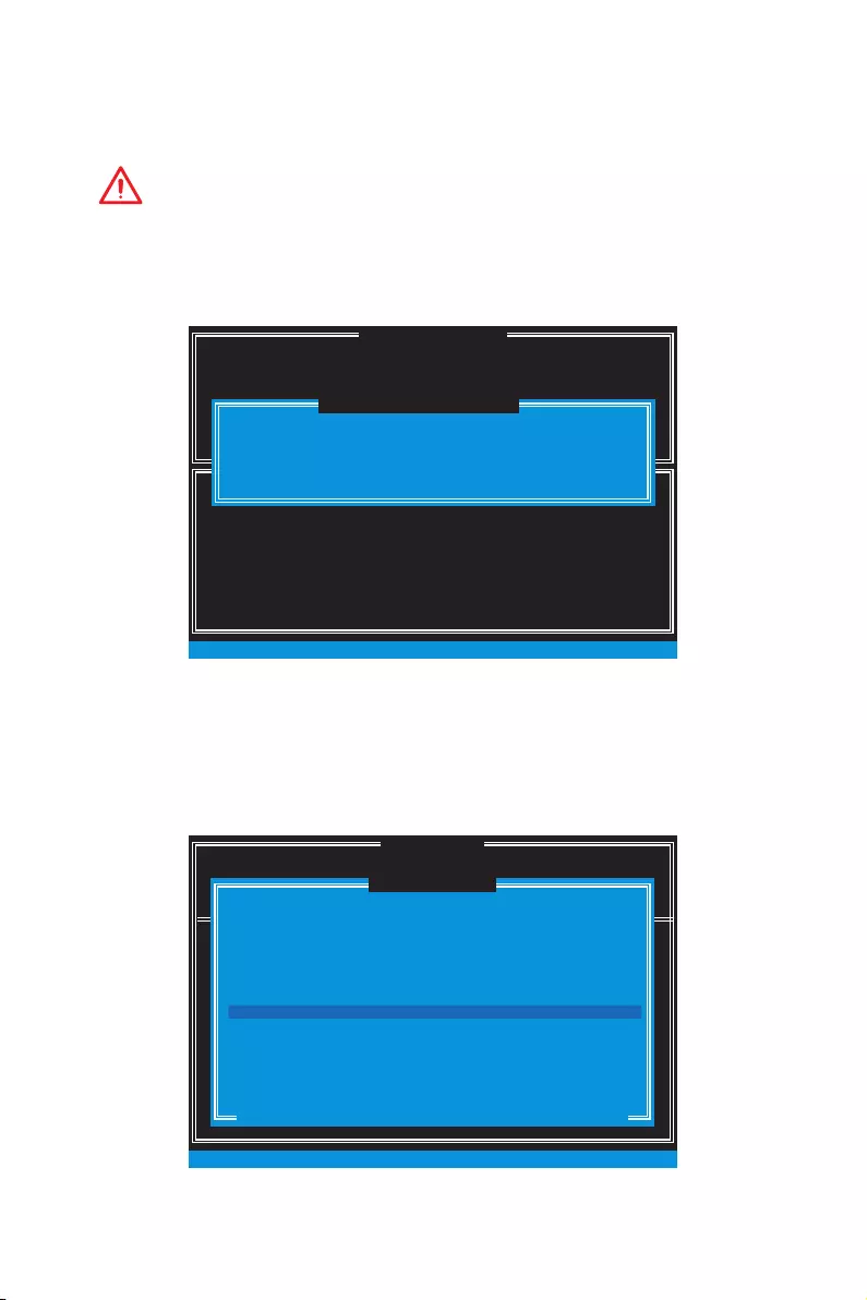
117
RAID Configuration
Removing a RAID Volume
Here you can delete the RAID volume, but please be noted that all data on RAID drives
will be lost.
Important
If your system currently boots to RAID and you delete the RAID volume in the IRST
Option ROM, your system will become unbootable.
Select option Delete RAID Volume from the main menu screen and press Enter key to
select a RAID volume for deletion. Then press Delete key to delete the selected RAID
volume. The following screen appears.
[ ]
DELETE VOLUME MENU
[ ]
HELP
Deleting a volume will reset the disks to non-RAID.
[ ↑↓] — Select [ESC] — Previous Menu [DEL] — Delete Volume
WARNING : ALL DISK DATA WILL BE DELETED.
(This does not apply to Recovery volumes)
Name Level Drives Capacity Status Bootable
Volume0 RAID1(Mirror) 2 XXX.XGB Normal Yes
ALL DATA IN THE VOLUME WILL BE LOST!
(This does not apply to Recovery volumes)
Are you sure you want to delete “Volume0”? (Y / N) :
DELETE VOLUME VERIFICATION
[ ]
Press Y key to accept the volume deletion.
Resetting Disks to Non-RAID
Select option Reset Disks to Non-RAID from the main menu screen and press Enter
to delete the RAID volume and remove any RAID structures from the drives. Use the
Space key to select the disks and press Enter key. A confirmation sentence will appear
below, and then press Y key to accept the selection
DISK / VOLUME INFORMATION
[ ]
4. Recovery Volume Options
4. Recovery Volume Options
5. Exit
RAID Volumes :
None dened.
Physical Devices :
Port Device Model Serial # Size Type/Status (Vol ID)
1 XXXX-XXXXXXXX XXXXXXXXXXXXXX XXX.XGB Non-RAID Disk
2 XXXX-XXXXXXXX XXXXXXXXXXXXXX XXX.XGB Non-RAID Disk
[ ↑↓] — Select [ESC] — Exit [ENTER] — Select Menu
1. Create RAID Volume
2. Delete RAID Volume
Resetting RAID disk will remove its RAID structures and revert it
to a non-RAID disk.
[ ]
RESET RAID DATA
WARNING : Resetting a disk causes all data on the disk to be lost.
(This does not apply to Recovery volumes)
Select the disks that should be reset.
[ ↑↓] — Previous/ Next [SPACE] — Selects [ENTER] — Selection Complete
Port Drive Model Serial # Size Status
1 XXXX-XXXXXXXX XXXXXXXXXXXXXX XXX.XGB Member Disk
2 XXXX-XXXXXXXX XXXXXXXXXXXXXX XXX.XGB Member Disk
[ ]
MAIN MENU

118 RAID Configuration
Important
y
You will lose all data on the RAID drives and any internal RAID structures when you
perform this operation.
y
Possible reasons to Reset Disks to Non-RAID could include issues such as
incompatible RAID configurations or a failed volume or failed disk.
Recovery Volume Options
Select option Recovery Volume Options from the main menu screen and press Enter
to change recovery volume mode. The following screen appears:
[ ]
RECOVERY VOLUME OPTIONS
[ ]
HELP
Enable Only Recovery Disk — enables recovery disk if available and
disables master disk.
Enable Only Master Disk — enables master disk if available and
disables recovery disk.
Actions will result in change from Continuous Update mode to On-Request.
[ ↑↓] — select [ESC] — Previous Menu [ENTER] — Select
1. Enable Only Recovery Disk
2. Enable Only Master Disk
Recovery mode will change from Continuous Update to On-Request after you enable
Only Recovery Disk or Only Master Disk.
Degraded RAID Array
A RAID 1, RAID 5 or RAID 10 volume is reported as degraded when one of its hard
drive members fails or is temporarily disconnected, and data mirroring is lost. As a
result, the system can only utilize the remaining functional hard drive member. To
re-establish data mirroring and restore data redundancy, refer to the procedure below
that corresponds to the current situation.
RAID Volumes
ID Name Level Strip Size Status Bootable
0 Volume0 RAID 1(Mirror) N/A XXX.XGB Degraded Yes
Physical Disks:
Port Device Model Serial # Size Type/Status(Vol ID)
1 XXXXXXXXXXXXX XXXXXXXXXXXXX XXX.XGB Member Disk (0)
2 XXXXXXXXXXXXX XXXXXXXXXXXXX XXX.XGB Member Disk (0)
Press <CTRL-I> to enter Conguration Utility..
Missing Hard Drive Member
1. Power off.
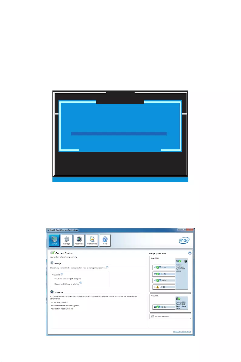
119
RAID Configuration
2. Reconnect the hard drive.
3. Reboot to Windows®; the rebuild will occur automatically.
Failed Hard Drive Member
1. Power off.
2. Replace the failed hard drive with a new one that is of equal or greater capacity.
3. Reboot the system to IRST Option ROM by press Ctrl + I keys during the POST.
4. Select the port of the destination disk for rebuilding, and then press Enter.
DISK / VOLUME INFORMATION
[ ]
4. Recovery Volume Options
4. Recovery Volume Options
5. Exit
RAID Volumes :
None dened.
Physical Devices :
Port Device Model Serial # Size Type/Status (Vol ID)
1 XXXX-XXXXXXXX XXXXXXXXXXXXXX XXX.XGB Non-RAID Disk
2 XXXX-XXXXXXXX XXXXXXXXXXXXXX XXX.XGB Non-RAID Disk
[ ↑↓] — Select [ESC] — Exit [ENTER] — Select Menu
1. Create RAID Volume
2. Delete RAID Volume
“Degraded” volume and disk available for rebuilding detected. Selecting
a disk initiates a rebuild. Rebuild completes in the operating system.
[ ]
DEGRADED VOLUME DETECTED
Select the port of the destination disk for rebuilding (ESC to exit):
[ ↑↓] — Previous/ Next [ENTER] — Select [ESC] — Exit
Port Drive Model Serial # Size
1 XXXX-XXXXXXXX XXXXXXXXXXXXXX XXX.XGB
[ ]
MAIN MENU
5. Exit IRST Option ROM, reboot to Windows®.
6. When prompted to rebuild the RAID volume, click Yes.
7. The Intel® Rapid Storage Technology application will be launched. Right-click
the new hard drive and select Rebuild to this Disk. The Rebuild Wizard will be
launched which will guide you through the process of rebuilding to the new hard
drive.
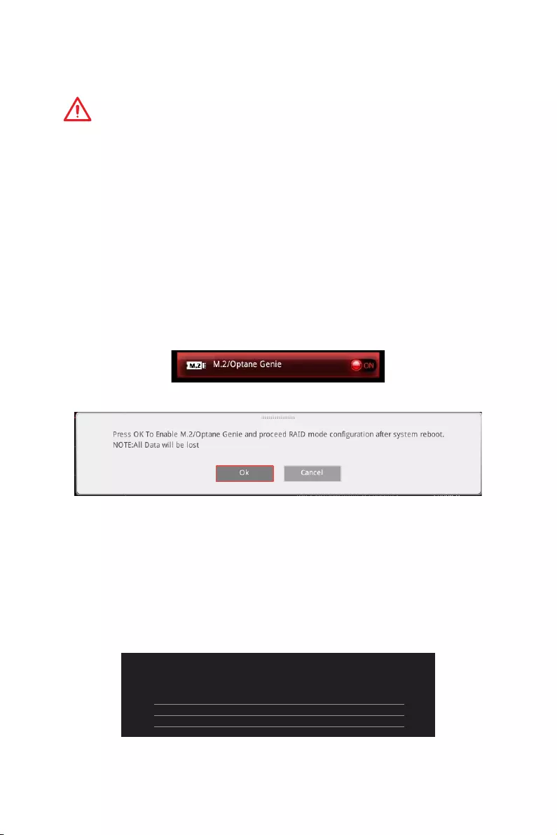
120 RAID Configuration
M.2 PCIe SSD RAID
You can create a M.2 PCIe SSD RAID volume with M.2/Optane Genie or UEFI BIOS.
Important
y
Please note that you must install M.2 SSDs of the same model and type in the M.2
slots to create the RAID 0 volume.
y
During windows setup, the RAID driver may be required and you can find the RAID
driver in MSI Driver Disc.
y
You can use MSI SMART TOOL to build the Windows
®
7/ 8.1/ 10 installation drive that
includes RAID driver.
y
If your system currently boots to M.2 PCIe SSD RAID and you delete the RAID volume,
your system will become unbootable.
y
When you delete the M.2 PCIe SSD RAID volume, please be noted that all data on M.2
PCIe SSDs will be lost.
Creating a M.2 PCIe SSD RAID with M.2/Optane Genie
1. Access the BIOS setup.
2. Enable M.2/Optane Genie by clicking the M.2/Optane Genie item.
3. Click Ok in the dialog.
4. Press F10 to save configuration and exit.
Creating a M.2 PCIe SSD RAID with UEFI BIOS
1. Access the BIOS setup
2. Switch to Advanced Mode by pressing F7 key.
3. Go to Settings > Advanced > Windows OS Configuration.
4. Set Windows 8.1/10 WHQL Support to Enabled.
5. Go to Settings > Advanced > Integrated Peripherals.
Setting\Advanced\Integrated Peripherals
SATA Conguration
SATA Mode [RAID Mode]
M2_1 Pcie Storage Remapping [Enabled]
M2_2 Pcie Storage Remapping [Enabled]
6. Set SATA Mode to RAID Mode.

121
RAID Configuration
7. Set both M2_1 Pcie Storage Remapping and M2_2 Pcie Storage Remapping to
Enabled.
8. Press F10 to save and exit and then press the Enter key to select Yes.
9. Reboot the system and access the BIOS setup again.
10. Switch to Advanced Mode by pressing F7 key.
11. Go to Settings > Advanced > Intel(R) Rapid Storage Technology.
12. Select Create RAID Volume and press Enter key.
…\Intel(R) Rapid Storage Technology\
Create RAID Volume
Create RAID Volume
Name: Volume1
RAID Level: [RAID0(Stripe)]
Select Disks:
PCIe, XXXXX XXXXXXXX-XXXX, XXXGB [X]
PCIe, XXXXX XXXXXXXX-XXXX, XXXGB [X]
Strip Size: [XXKB]
Capacity (MB): XXXXXX
Create Volume
13. Enter in a volume name.
14. Select the RAID level.
15. Use Space key to select the both PCIe SSDs.
16. If creating RAID 0, select the Strip Size; it is recommended that it be left at the
default value.
17. Go to the Create Volume field and press Enter.
Removing a M.2 PCIe SSD RAID Volume with M.2/Optane Genie
1. Access the BIOS setup.
2. Disable M.2/Optane Genie by clicking M.2/Optane Genie item.
3. Click Ok in the dialog.
4. Press F10 to save configuration and exit.

122 RAID Configuration
Removing a M.2 PCIe SSD RAID Volume with UEFI BIOS
1. Access the BIOS setup.
2. Switch to Advanced Mode by pressing F7 key.
3. Go to Settings > Advanced > Intel(R) Rapid Storage Technology.
4. Select a RAID volume and press Enter key.
5. Go to the Delete field and press Enter. The following screen appears
…\RAID VOLUME INFO\
Delete
Delete
Delete the RAID volume?
ALL DATA ON VOLUME WILL BE LOST!
Yes
No
6. Go to the Yes field and press Enter key to accept the volume deletion.
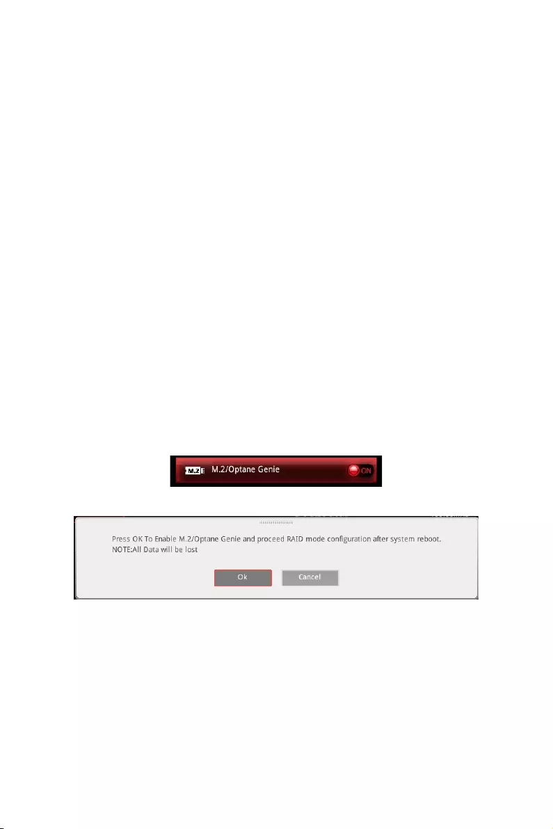
123
Intel® Optane™ Memory Configuration
Intel® Optane™ Memory Configuration
Intel® Optane™ memory can accelerate the Windows 10 64bit operating system. This
section describes how to install and remove the Intel® Optane™ memory.
System Requirements
yIntel® Optane™ memory ready MSI® motherboards
ySupported 7th Gen, or later, Intel® Core™ — i Processor
ySystem BIOS that supports the Intel® Rapid Storage Technology (Intel® RST) 15.5 or
later driver
yOperating system: Windows 10 64 bit (UEFI mode).
yIntel® Optane™ Memory Module
Installing the Intel® Optane™ memory
1. Update BIOS (refer to the Updating BIOS section).
2. Install the Intel® Optane™ memory module.
Power off the system.
Refer to the Specifications for location to install your Intel® Optane™ memory
module.
Install the Intel® Optane™ memory module into the M.2 slot.
3. Enable M.2/Optane Genie
Power on and press Delete key to enter BIOS Setup menu.
Enable M.2/Optane Genie by clicking the M.2/Optane Genie item.
Click Ok in the dialog.
Press F10 to save configuration and exit.
4. Install the Intel® Rapid Storage Technology 15.5
Reboot to operating system.
Install the Intel® Rapid Storage Technology 15.5
Reboot System.
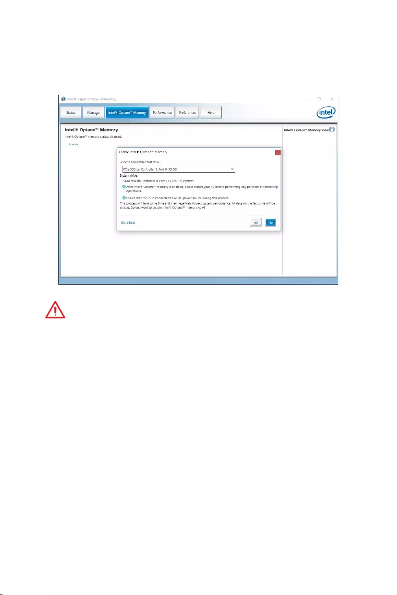
124 Intel® Optane™ Memory Configuration
5. Enable Intel® Optane™ Memory.
Enable Intel® Optane™ Memory via the Intel® Optane™ memory application
(auto-launches upon reboot).
Click Yes in the dialog.
Reboot System.
WARNING
Once you enable Intel
®
Optane™ memory, in order to prevent seriously damage your
operating system, please follow the cautions listed below.
y
DO NOT set the SATA mode back to AHCI in BIOS.
y
DO NOT revert back to older version of the BIOS.
y
DO NOT remove the Intel
®
Optane™ memory module.
y
DO NOT replace the CPU that is not supported by Intel
®
Optane™ Memory.
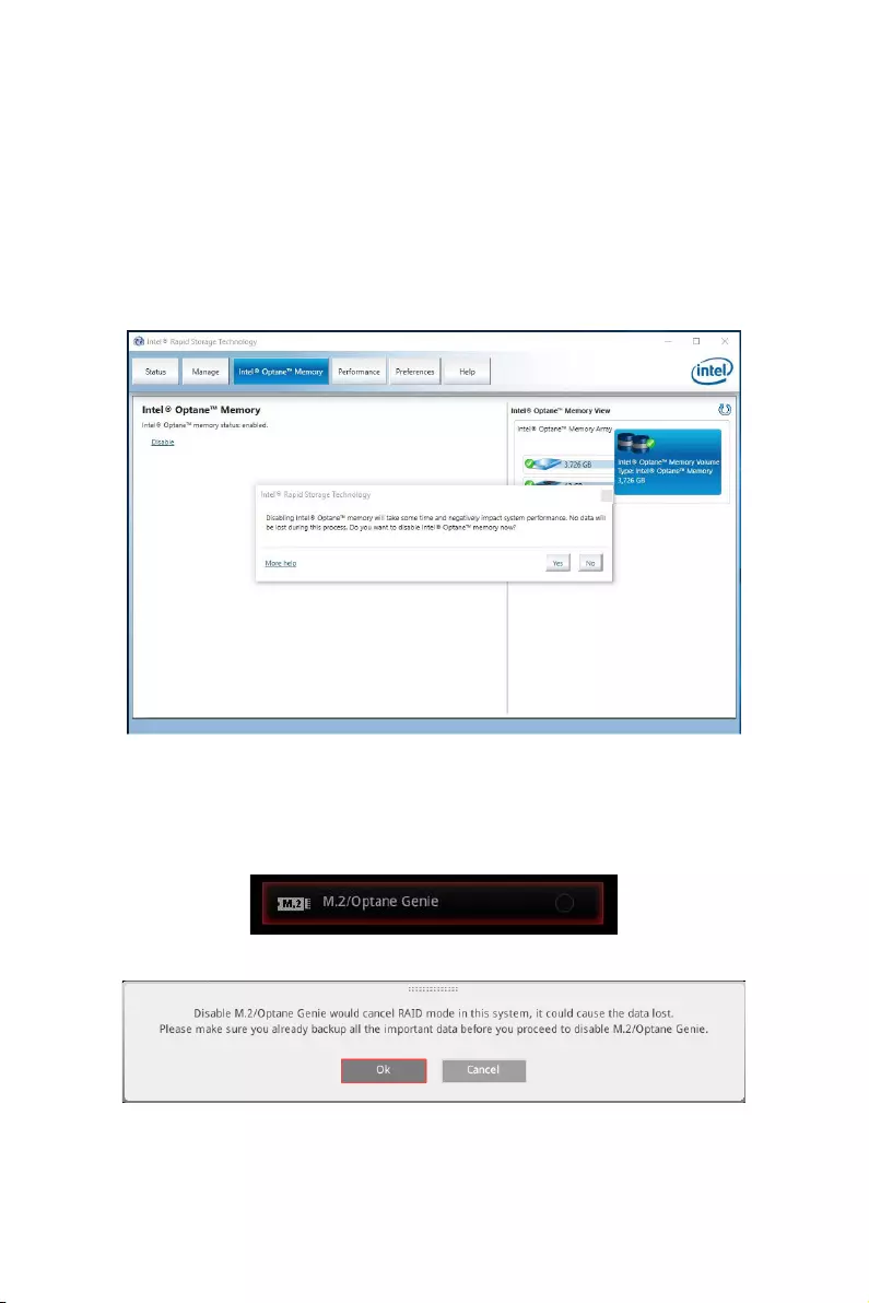
125
Intel® Optane™ Memory Configuration
Removing the Intel® Optane™ memory
If you no longer want to use Intel® Optane™ memory, you have to disable the Intel®
Optane™ memory before removing the Intel® Optane™ memory module to avoid
operating system damage. Please follow the steps below to remove the Intel® Optane™
memory.
1. Disable Intel® Optane™ Memory.
Disable Intel® Optane™ Memory via the Intel® Optane™ memory application
(Intel® Rapid Storage Technology).
Click Yes in the dialog.
Reboot System.
2. Disable M.2/Optane Genie
Press Delete key to enter BIOS Setup menu during POST.
Disable M.2/Optane Genie by clicking M.2/Optane Genie item.
Click Ok in the dialog.
Press F10 to save configuration and exit.
3. Remove the Intel® Optane™ memory module.
Power off the system.
Remove the Intel® Optane™ memory module.
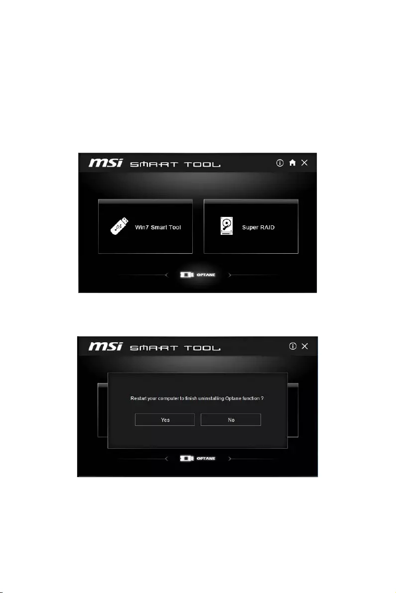
126 Intel® Optane™ Memory Configuration
Troubleshooting
When you installed the operating system in AHCI mode, the system will be changed to
RAID/ Optane mode after enabling Intel® Optane™ Memory. If you want to disable Intel
Optane Memory and switch BIOS setting from RAID/ Optane mode back to AHCI mode,
that may cause operating system damage. MSI has developed a software assistance
for this problem. You can disable Intel® Optane™ Memory and switch back to AHCI
mode while keep the system bootable with MSI SMART TOOL.
Please follow the steps below to disable Intel® Optane™ Memory and set the SATA
mode back to AHCI.
1. Run MSI SMART TOOL.
2. Click the OPTANE icon. (Note: the OPTANE icon is only available when Intel®
Optane™ Memory has been enabled)
3. Click Yes.
4. Reboot System.

127
Troubleshooting
Troubleshooting
Before sending the motherboard for RMA
repair, try to go over troubleshooting
guide first to see if your got similar
symptoms as mentioned below.
The power is not on.
yConnect the AC power cord to an
electrical outlet securely.
yCheck if all ATX power connectors like
ATX_PWR1, CPU_PWR1, CPU_PWR2 are
connected from the power supply to the
motherboard?
ySome power supply units have a power
button on the rear side, make sure the
button is turned on.
yCheck if the power switch cable is
connected to JFP1 pin header properly.
yVerify the Clear CMOS jumper JBAT1 is
set to Keep DATA.
yTest with another known working power
supply of equal or greater wattage.
The power is on, but no signal to
monitor
yConnect the monitor power cord to a
electrical outlet securely.
yMake sure the monitor is turned on.
ySelect different inputs on the monitor.
yIf 3 long beeps are heard, remove all
memory modules and try to install only
one memory module in the DIMMC1 slot
first and then restart the computer.
yIf 1 long 2 short beeps are heard,
remove and reinstall the graphics card
and then restart the computer.
yTest with another known working
graphics card.
The computer does not boot after
updating the BIOS
yClear the CMOS.
yUse the secondary BIOS to bootup the
system (Only for motherboard with Dual
BIOS)
Lost BIOS password
yClear the CMOS, but that will cause
you to lose all customized settings in the
BIOS.
There is no audio
yAdjust the volume.
yConnect the speakers/headphones to
audio ports on the motherboard rear IO
panel.
yRemove secondary speakers/
headphones, HDMI cables, USB audio
devices.
yTest with another known working
speaker or headphone.
There is no network
yMake sure the network chipset driver
has been installed.
yVerify if the network cable is properly
connected and make sure the LAN port
LEDs are properly illuminated.
yVerify your TCP/IP settings.
yRestart or reset your router.
yTest with another known working LAN
cable.
The USB device is not working
yMake sure your USB drive driver has
been installed.
yVerify if USB device is listed in
Windows® Device Manager.
yConnect the USB device to other USB
port on the motherboard rear IO panel.
128 Regulatory Notices
Regulatory Notices
FCC Compliance Statement
Note: This equipment has been tested and found to
comply with the limits for a Class B digital device,
pursuant to part 15 of the FCC Rules. These limits
are designed to provide reasonable protection against
harmful interference in a residential installation. This
equipment generates, uses and can radiate radio
frequency energy and, if not installed and used in
accordance with the instructions, may cause harmful
interference to radio communications. However, there
is no guarantee that interference will not occur in a
particular installation. If this equipment does cause
harmful interference to radio or television reception,
which can be determined by turning the equipment
off and on, the user is encouraged to try to correct the
interference by one or more of the following measures:
yReorient or relocate the receiving antenna.
yIncrease the separation between the equipment
and receiver.
yConnect the equipment into an outlet on a circuit
different from that to which the receiver is
connected.
yConsult the dealer or an experienced radio/TV
technician for help.
Caution: Changes or modifications not expressly
approved by the party responsible for compliance could
void the user’s authority to operate the equipment.
Tested to comply with FCC standards
FOR HOME OR OFFICE USE
This device complies with part 15 of the FCC Rules.
Operation is subject to the following two conditions:
(1) This device may not cause harmful interference, and
(2) this device must accept any interference received,
including interference that may cause undesired
operation.
B급 기기 (가정용 방송통신기자재)
이 기기는 가정용(B급) 전자파적합기기로서 주
로 가정에서 사용하는 것을 목적으로 하며, 모
든 지역에서 사용할 수 있습니다.
クラスB情報技術装置
この装置は、クラスB情報技術装置です。この
装置は、家庭環境で使用することを目的として
い ま す が、こ の 装 置 が ラ ジ オ や テ レ ビ ジ ョ ン 受
信機に近接して使用されると、受信障害を引き起こすこと
があります。取扱説明書に従って
正しい取り扱いをして下さい
VCCI-B
C-Tick Compliance
Battery Information
European Union:
Batteries, battery packs, and
accumulators should not be disposed of as
unsorted household waste. Please use the
public collection system to return, recycle,
or treat them in compliance with the local
regulations.
Taiwan:
廢電池請回收
For better environmental protection, waste
batteries should be collected separately
for recycling or special disposal.
California, USA:
The button cell battery may contain
perchlorate material and requires special
handling when recycled or disposed of in
California.
For further information please visit:
http://www.dtsc.ca.gov/hazardouswaste/perchlorate/
CAUTION: There is a risk of explosion, if battery is
incorrectly replaced.
Replace only with the same or equivalent type
recommended by the manufacturer.
Chemical Substances Information
In compliance with chemical substances regulations,
such as the EU REACH Regulation (Regulation EC
No. 1907/2006 of the European Parliament and the
Council), MSI provides the information of chemical
substances in products at:
http://www.msi.com/html/popup/csr/evmtprtt_pcm.
html
Environmental Policy
yThe product has been designed to
enable proper reuse of parts and
recycling and should not be thrown
away at its end of life.
yUsers should contact the local
authorized point of collection for recycling and
disposing of their end-of-life products.
yVisit the MSI website and locate a nearby distributor
for further recycling information.
yUsers may also reach us at gpcontdev@msi.com for
information regarding proper Disposal, Take-back,
Recycling, and Disassembly of MSI products.
WEEE (Waste Electrical and
Electronic Equipment) Statement
ENGLISH
To protect the global environment and as
an environmentalist, MSI must remind
you that…
Under the European Union (“EU”) Directive
on Waste Electrical and Electronic
Equipment, Directive 2002/96/EC, which
takes effect on August 13, 2005, products of “electrical
and electronic equipment” cannot be discarded as
municipal wastes anymore, and manufacturers of
covered electronic equipment will be obligated to take
back such products at the end of their useful life. MSI
will comply with the product take back requirements
at the end of life of MSI-branded products that are
sold into the EU. You can return these products to local
collection points.
DEUTSCH
Hinweis von MSI zur Erhaltung und Schutz unserer
Umwelt
Gemäß der Richtlinie 2002/96/EG über Elektro- und
Elektronik-Altgeräte dürfen Elektro- und Elektronik-
Altgeräte nicht mehr als kommunale Abfälle entsorgt
werden. MSI hat europaweit verschiedene Sammel-
und Recyclingunternehmen beauftragt, die in die

129
Regulatory Notices
Europäische Union in Verkehr gebrachten Produkte,
am Ende seines Lebenszyklus zurückzunehmen.
Bitte entsorgen Sie dieses Produkt zum gegebenen
Zeitpunkt ausschliesslich an einer lokalen
Altgerätesammelstelle in Ihrer Nähe.
FRANÇAIS
En tant qu’écologiste et afin de protéger
l’environnement, MSI tient à rappeler ceci…
Au sujet de la directive européenne (EU) relative aux
déchets des équipement électriques et électroniques,
directive 2002/96/EC, prenant effet le 13 août 2005, que
les produits électriques et électroniques ne peuvent
être déposés dans les décharges ou tout simplement
mis à la poubelle. Les fabricants de ces équipements
seront obligés de récupérer certains produits en fin
de vie. MSI prendra en compte cette exigence relative
au retour des produits en fin de vie au sein de la
communauté européenne. Par conséquent vous pouvez
retourner localement ces matériels dans les points de
collecte.
РУССКИЙ
Компания MSI предпринимает активные действия
по защите окружающей среды, поэтому напоминаем
вам, что….
В соответствии с директивой Европейского
Союза (ЕС) по предотвращению загрязнения
окружающей среды использованным электрическим
и электронным оборудованием (директива
WEEE 2002/96/EC), вступающей в силу 13
августа 2005 года, изделия, относящиеся к
электрическому и электронному оборудованию,
не могут рассматриваться как бытовой мусор,
поэтому производители вышеперечисленного
электронного оборудования обязаны принимать
его для переработки по окончании срока службы.
MSI обязуется соблюдать требования по приему
продукции, проданной под маркой MSI на территории
EC, в переработку по окончании срока службы. Вы
можете вернуть эти изделия в специализированные
пункты приема.
ESPAÑOL
MSI como empresa comprometida con la protección
del medio ambiente, recomienda:
Bajo la directiva 2002/96/EC de la Unión Europea
en materia de desechos y/o equipos electrónicos,
con fecha de rigor desde el 13 de agosto de 2005,
los productos clasificados como “eléctricos y
equipos electrónicos” no pueden ser depositados
en los contenedores habituales de su municipio, los
fabricantes de equipos electrónicos, están obligados
a hacerse cargo de dichos productos al termino de
su período de vida. MSI estará comprometido con los
términos de recogida de sus productos vendidos en
la Unión Europea al final de su periodo de vida. Usted
debe depositar estos productos en el punto limpio
establecido por el ayuntamiento de su localidad o
entregar a una empresa autorizada para la recogida de
estos residuos.
NEDERLANDS
Om het milieu te beschermen, wil MSI u eraan
herinneren dat….
De richtlijn van de Europese Unie (EU) met betrekking
tot Vervuiling van Electrische en Electronische
producten (2002/96/EC), die op 13 Augustus 2005 in
zal gaan kunnen niet meer beschouwd worden als
vervuiling. Fabrikanten van dit soort producten worden
verplicht om producten retour te nemen aan het
eind van hun levenscyclus. MSI zal overeenkomstig
de richtlijn handelen voor de producten die de
merknaam MSI dragen en verkocht zijn in de EU. Deze
goederen kunnen geretourneerd worden op lokale
inzamelingspunten.
SRPSKI
Da bi zaštitili prirodnu sredinu, i kao preduzeće koje
vodi računa o okolini i prirodnoj sredini, MSI mora da
vas podesti da…
Po Direktivi Evropske unije (“EU”) o odbačenoj
ekektronskoj i električnoj opremi, Direktiva 2002/96/
EC, koja stupa na snagu od 13. Avgusta 2005, proizvodi
koji spadaju pod “elektronsku i električnu opremu”
ne mogu više biti odbačeni kao običan otpad i
proizvođači ove opreme biće prinuđeni da uzmu natrag
ove proizvode na kraju njihovog uobičajenog veka
trajanja. MSI će poštovati zahtev o preuzimanju ovakvih
proizvoda kojima je istekao vek trajanja, koji imaju MSI
oznaku i koji su prodati u EU. Ove proizvode možete
vratiti na lokalnim mestima za prikupljanje.
POLSKI
Aby chronić nasze środowisko naturalne oraz jako
firma dbająca o ekologię, MSI przypomina, że…
Zgodnie z Dyrektywą Unii Europejskiej (“UE”) dotyczącą
odpadów produktów elektrycznych i elektronicznych
(Dyrektywa 2002/96/EC), która wchodzi w życie 13
sierpnia 2005, tzw. “produkty oraz wyposażenie
elektryczne i elektroniczne “ nie mogą być traktowane
jako śmieci komunalne, tak więc producenci tych
produktów będą zobowiązani do odbierania ich w
momencie gdy produkt jest wycofywany z użycia.
MSI wypełni wymagania UE, przyjmując produkty
(sprzedawane na terenie Unii Europejskiej) wycofywane
z użycia. Produkty MSI będzie można zwracać w
wyznaczonych punktach zbiorczych.
TÜRKÇE
Çevreci özelliğiyle bilinen MSI dünyada çevreyi
korumak için hatırlatır:
Avrupa Birliği (AB) Kararnamesi Elektrik ve Elektronik
Malzeme Atığı, 2002/96/EC Kararnamesi altında 13
Ağustos 2005 tarihinden itibaren geçerli olmak üzere,
elektrikli ve elektronik malzemeler diğer atıklar
gibi çöpe atılamayacak ve bu elektonik cihazların
üreticileri, cihazların kullanım süreleri bittikten sonra
ürünleri geri toplamakla yükümlü olacaktır. Avrupa
Birliği’ne satılan MSI markalı ürünlerin kullanım
süreleri bittiğinde MSI ürünlerin geri alınması isteği ile
işbirliği içerisinde olacaktır. Ürünlerinizi yerel toplama
noktalarına bırakabilirsiniz.
ČESKY
Záleží nám na ochraně životního prostředí — společnost
MSI upozorňuje…
Podle směrnice Evropské unie (“EU”) o likvidaci
elektrických a elektronických výrobků 2002/96/
EC platné od 13. srpna 2005 je zakázáno likvidovat
“elektrické a elektronické výrobky” v běžném
komunálním odpadu a výrobci elektronických
výrobků, na které se tato směrnice vztahuje, budou
povinni odebírat takové výrobky zpět po skončení
jejich životnosti. Společnost MSI splní požadavky na
odebírání výrobků značky MSI, prodávaných v zemích
EU, po skončení jejich životnosti. Tyto výrobky můžete
odevzdat v místních sběrnách.
MAGYAR
Annak érdekében, hogy környezetünket megvédjük,
illetve környezetvédőként fellépve az MSI emlékezteti
Önt, hogy …
Az Európai Unió („EU”) 2005. augusztus 13-án hatályba
lépő, az elektromos és elektronikus berendezések

130 Regulatory Notices
hulladékairól szóló 2002/96/EK irányelve szerint
az elektromos és elektronikus berendezések
többé nem kezelhetőek lakossági hulladékként,
és az ilyen elektronikus berendezések gyártói
kötelessé válnak az ilyen termékek visszavételére
azok hasznos élettartama végén. Az MSI betartja a
termékvisszavétellel kapcsolatos követelményeket
az MSI márkanév alatt az EU-n belül értékesített
termékek esetében, azok élettartamának végén. Az
ilyen termékeket a legközelebbi gyűjtőhelyre viheti.
ITALIANO
Per proteggere l’ambiente, MSI, da sempre amica della
natura, ti ricorda che….
In base alla Direttiva dell’Unione Europea (EU) sullo
Smaltimento dei Materiali Elettrici ed Elettronici,
Direttiva 2002/96/EC in vigore dal 13 Agosto 2005,
prodotti appartenenti alla categoria dei Materiali
Elettrici ed Elettronici non possono più essere eliminati
come rifiuti municipali: i produttori di detti materiali
saranno obbligati a ritirare ogni prodotto alla fine
del suo ciclo di vita. MSI si adeguerà a tale Direttiva
ritirando tutti i prodotti marchiati MSI che sono stati
venduti all’interno dell’Unione Europea alla fine del
loro ciclo di vita. È possibile portare i prodotti nel più
vicino punto di raccolta
日本JIS C 0950材質宣言
日本工業規格JIS C 0950に よ り、2006年7月1日以降に販
売される特定分野の電気および電子機器について、製造
者による含有物質の表示が義務付けられます。
http://www.msi.com/html/popup/csr/cemm_jp.html
http://tw.msi.com/html/popup/csr_tw/cemm_jp.html
India RoHS
This product complies with the “India E-waste
(Management and Handling) Rule 2011” and
prohibits use of lead, mercury, hexavalent chromium,
polybrominated biphenyls or polybrominated diphenyl
ethers in concentrations exceeding 0.1 weight % and
0.01 weight % for cadmium, except for the exemptions
set in Schedule 2 of the Rule.
Türkiye EEE yönetmeliği
Türkiye Cumhuriyeti: EEE Yönetmeliğine Uygundur
Україна обмеження на наявність
небезпечних речовин
Обладнання відповідає вимогам Технічного
регламенту щодо обмеження використання
деяких небезпечних речовин в електричному та
електронному обладнані, затвердженого постановою
Кабінету Міністрів України від 3 грудня 2008 № 1057.
Việt Nam RoHS
Kể từ ngày 01/12/2012, tất cả các sản phẩm do công
ty MSI sản xuất tuân thủ Thông tư số 30/2011/TT-BCT
quy định tạm thời về giới hạn hàm lượng cho phép của
một số hóa chất độc hại có trong các sản phẩm điện,
điện tử”
Wireless Radio Use
This device is restricted to indoor use when operating
in the 2.4GHz, 5GHz frequency band.
Cet appareil doit être utilisé à l’intérieur.
당해 무선설비는 운용중 전파혼신 가능성이 있음.
この製品は、周波数帯域 2.4GHz, 5GHz で動作していると
きは、屋内においてのみ使用可能です。
NCC無線設備警告聲明
工作頻率2.4GHz, 5GHz該頻段限於室內使用。
經型式認證合格之低功率射頻電機,非經許可,公司、商
號或使用者均不得擅自變更頻率、加大功率或變更原設
計之特性及功能。
低功率射頻電機之使用不得影響飛航安全及干擾合法通
信;經發現有干擾現象時,應立即停用,並改善至無干擾時
方得繼續使用。前項合法通信,指依電信法規定作業之無
線電通信。低功率射頻電機須忍受合法通信或工業、科學
及醫療用電波輻射性電機設備之干擾。
European Union Regulatory Notices
Declaration of Conformity
Products Sold Before 13 June 2017
Products bearing the CE marking comply
with one or more of the following EU Directives as may
be applicable:
R&TTE Directive 1999/5/EC; Low Voltage Directive
2014/35/EU; EMC Directive 2014/30/EU; RoHS
Directive 2011/65/EU.
Compliance with these directives is assessed using
applicable European Harmonized Standards.
The point of contact for regulatory matters is MSI, MSI-
NL Eindhoven 5706 5692 ER Son.
Products Sold After 12 June 2017
Products bearing the CE marking comply with one
or more of the following EU Directives as may be
applicable:
RED 2014/53/EU; Low Voltage Directive 2014/35/EU;
EMC Directive 2014/30/EU; RoHS Directive 2011/65/EU.
Compliance with these directives is assessed using
applicable European Harmonized Standards.
The point of contact for regulatory matters is MSI, MSI-
NL Eindhoven 5706 5692 ER Son.
Products with radio functionality (EMF)
This product incorporates a radio transmitting
and receiving device. For computers in normal
use, a separation distance of 20 cm ensures that
radio frequency exposure levels comply with EU
requirements. Products designed to be operated
at closer proximities, such as tablet computers,
comply with applicable EU requirements in typical
operating positions. Products can be operated without
maintaining a separation distance unless otherwise
indicated in instructions specific to the product.
Restrictions for products with radio functionality
CAUTION: IEEE 802.11x wireless LAN with
5.15~5.35 GHz frequency band is restricted
for indoor use only in all European Union
member states, EFTA (Iceland, Norway,
Liechtenstein), and most other European
countries (e.g., Switzerland, Turkey, Republic of
Serbia). Using this WLAN application outdoors might
lead to interference issues with existing radio services.
CAUTION: Fixed outdoor installations for WiGig
application (57~66 GHz frequency band) are excluded
in all European Union member states, EFTA (Iceland,
Norway, Liechtenstein), and other European countries
(e.g., Switzerland, Turkey, Republic of Serbia).
Radio frequency bands and maximum power levels
Features :802.11 a/b/g/n/ac, BT
Frequency Range :2.4GHz, 5GHz
Modulation :FHSS, DSSS, OFDM
Power Output :10, 20, 23
Channel Band Width :1, 5, 20 ,40 , 80MHz
131
Regulatory Notices
Copyright
Micro-Star Int’l Co.,Ltd.
Copyright © 2017 All rights reserved.
The material in this document is the intellectual
property of Micro-Star Int’l Co.,Ltd. We take every care
in the preparation of this document, but no guarantee
is given as to the correctness of its contents. Our
products are under continual improvement and we
reserve the right to make changes without notice.
Technical Support
If a problem arises with your system and no solution
can be obtained from the user guide, please
contact your place of purchase or local distributor.
Alternatively, please try the following help resources
for further guidance.
yVisit the MSI website for technical guide, BIOS
updates, driver updates, and other information:
http://www.msi.com
yRegister your product at: http://register.msi.com
Trademark Recognition
All product names used in this manual are the
properties of their respective owners and are
acknowledged.
Revision History
Version 1.0, 2017/05, First release.
产品中有害物质的名称及含量
部件名称
有害物质
铅
(Pb)
汞
(Hg)
镉
(Cd)
六价铬
(Cr(VI))
多溴联苯
(PBB)
多溴二苯醚
(PBDE)
印刷电路板组件*╳ ○ ○ ○ ○ ○
电池** ╳ ○ ○ ○ ○ ○
外部信号连接头 ╳ ○ ○ ○ ○ ○
线材 ╳ ○ ○ ○ ○ ○
本表格依据 SJ/T 11364 的规定编制。
○: 表示该有害物质在该部件所有均质材料中的含量均在 GB/T 26572 规定的限量要求以下。
╳: 表示该有害物质至少在该部件的某一均质材料中的含量超出 GB/T 26572 规定的限量要求,但所有部件都符合
欧盟RoHS要 求。
* 印刷电路板组件: 包括印刷电路板及其构成的零部件。
** 电池本体上如有环保使用期限标识,以本体标识为主。
■ 上述有毒有害物质或元素清单会依型号之部件差异而有所增减。
■ 產品部件本体上如有环保使用期限标识,以本体标识为主。
限用物質含有情況標示聲明書
單元
限用物質及其化學符號
鉛
(Pb)
汞
(Hg)
鎘
(Cd)
六價鉻
(Cr+6)
多溴聯苯
(PBB)
多溴二苯醚
(PBDE)
電路板 ○ ○ ○ ○ ○ ○
電子元件 - ○ ○ ○ ○ ○
金屬機構件 - ○ ○ ○ ○ ○
塑膠機構件 ○ ○ ○ ○ ○ ○
備考1. “超出0.1 wt %” 及 “超出0.01 wt %” 係指限用物質之百分比含量超出百分比含量基準值。
備考2. “○” 係指該項限用物質之百分比含量未超出百分比含量基準值。
備考3. “-” 係指該項限用物質為排除項目。

Quick Start
Thank you for purchasing the MSI® X299 GAMING PRO CARBON/
X299 GAMING PRO CARBON AC motherboard. This Quick Start
section provides demonstration diagrams about how to install
your computer. Some of the installations also provide video
demonstrations. Please link to the URL to watch it with the web
browser on your phone or tablet. You may have even link to the URL
by scanning the QR code.
Kurzanleitung
Danke, dass Sie das MSI® X299 GAMING PRO CARBON/ X299
GAMING PRO CARBON AC Motherboard gewählt haben. Dieser
Abschnitt der Kurzanleitung bietet eine Demo zur Installation
Ihres Computers. Manche Installationen bieten auch die
Videodemonstrationen. Klicken Sie auf die URL, um diese
Videoanleitung mit Ihrem Browser auf Ihrem Handy oder Table
anzusehen. Oder scannen Sie auch den QR Code mit Ihrem Handy,
um die URL zu öffnen.
Présentation rapide
Merci d’avoir choisi la carte mère MSI® X299 GAMING PRO CARBON/
X299 GAMING PRO CARBON AC. Ce manuel fournit une rapide
présentation avec des illustrations explicatives qui vous aideront à
assembler votre ordinateur. Des tutoriels vidéo sont disponibles pour
certaines étapes. Cliquez sur le lien fourni pour regarder la vidéo sur
votre téléphone ou votre tablette. Vous pouvez également accéder au
lien en scannant le QR code qui lui est associé.
Быстрый старт
Благодарим вас за покупку материнской платы MSI® X299
GAMING PRO CARBON/ X299 GAMING PRO CARBON AC. В этом
разделе представлена информация, которая поможет
вам при сборке комьютера. Для некоторых этапов
сборки имеются видеоинструкции. Для просмотра видео,
необходимо открыть соответствующую ссылку в веббраузере на вашем телефоне или планшете. Вы также
можете выполнить переход по ссылке, путем сканирования
QR-кода.
Quick Start
I
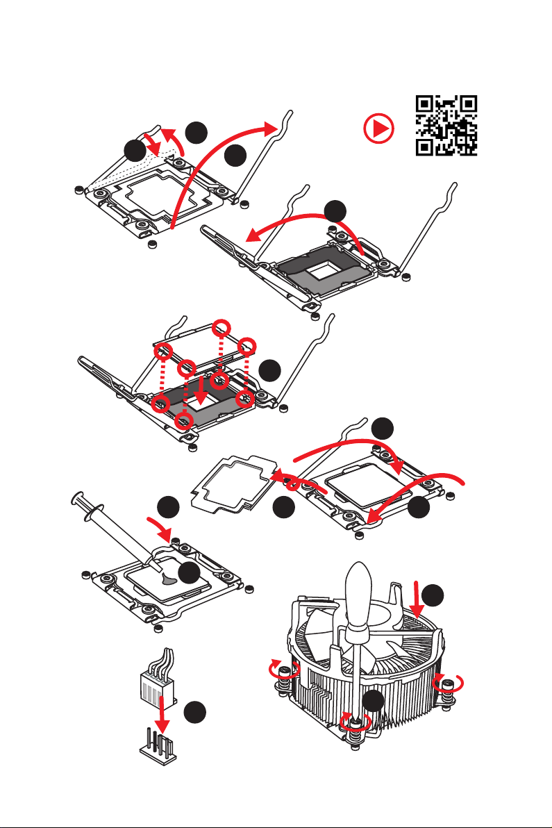
Installing a Processor/ Installation des Prozessors/ Installer un
processeur/ Установка процессора
1
3
2
4
5
6
Quick Start
II
789
10
11
12
13
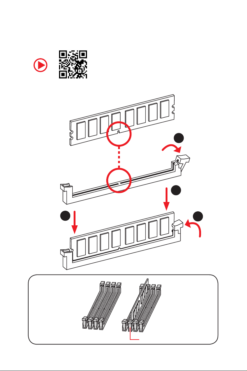
Installing DDR4 memory/ Installation des DDR4-Speichers/
Installer une mémoire DDR4/ Установка памяти DDR4
1
2
2
DIMMC1
3
Quick Start
III
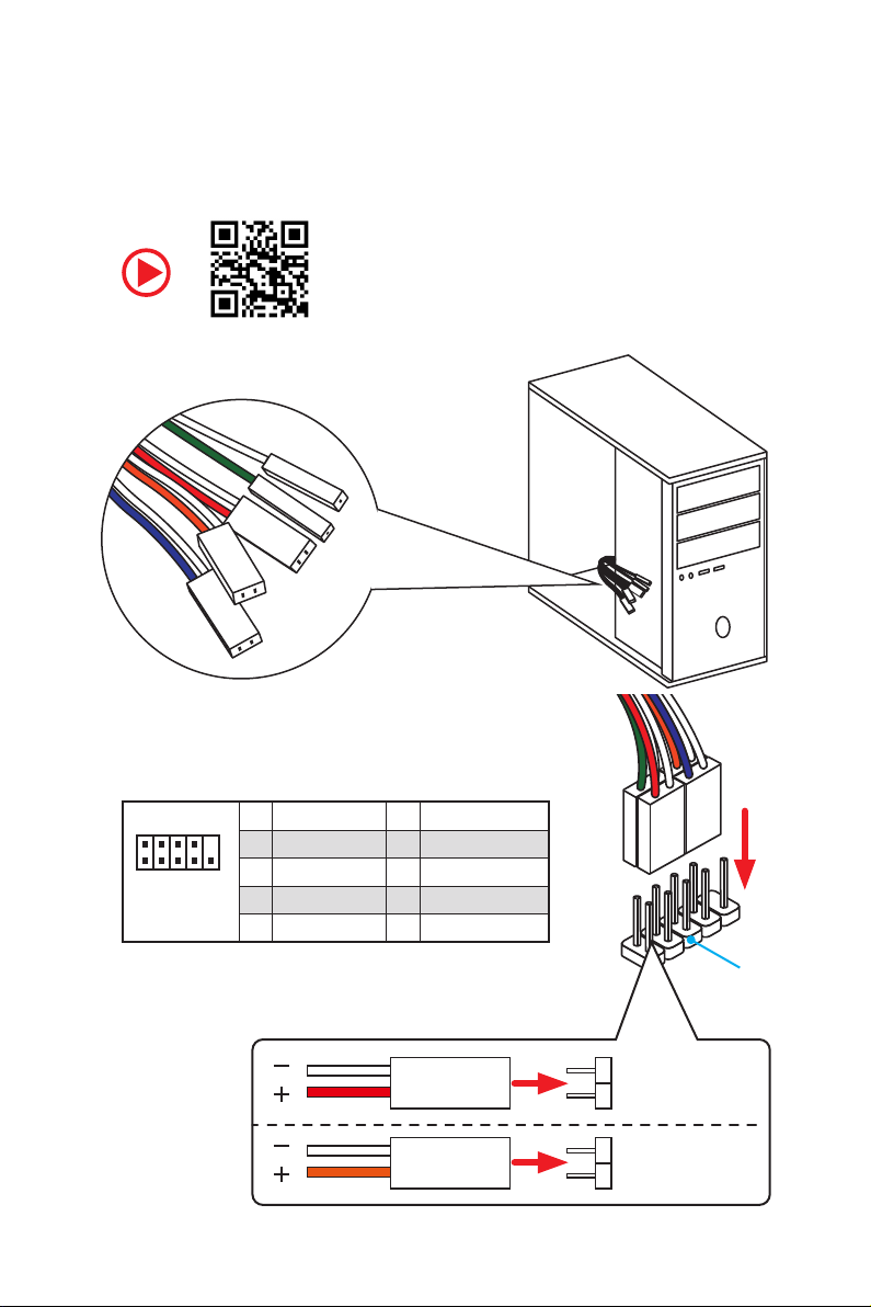
RESET SW
POWER SW
POWER LED+
POWER LED-
HDD LED
Connecting the Front Panel Header/ Anschließen der
Frontpanel-Stiftleiste/ Connecter un connecteur du panneau
avant/ Подключение разъемов передней панели
IV
2 10
1
Quick Start
JFP1
1 HDD LED + 2 Power LED +
3 HDD LED — 4 Power LED —
5 Reset Switch 6 Power Switch
9
7 Reset Switch 8 Power Switch
9 Reserved 10 No Pin
HDD LED
POWER LED
RESET SW
HDD LED
JFP1
HDD LED HDD LED +
POWER LED POWER LED +
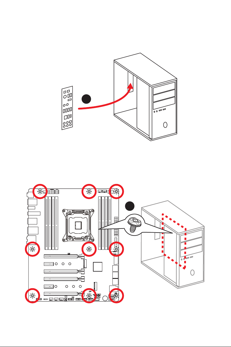
Installing the Motherboard/ Installation des Motherboards/
Installer la carte mère/ Установка материнской платы
1
2
Quick Start
V
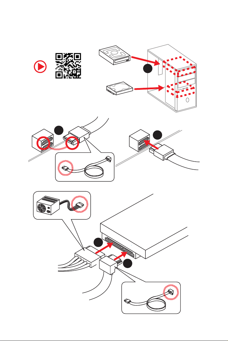
Installing SATA Drives/ Installation der SATA-Laufwerke/
Installer le disque dur SATA/ Установка дисков SATA
1
2
3
5
4
VI
Quick Start
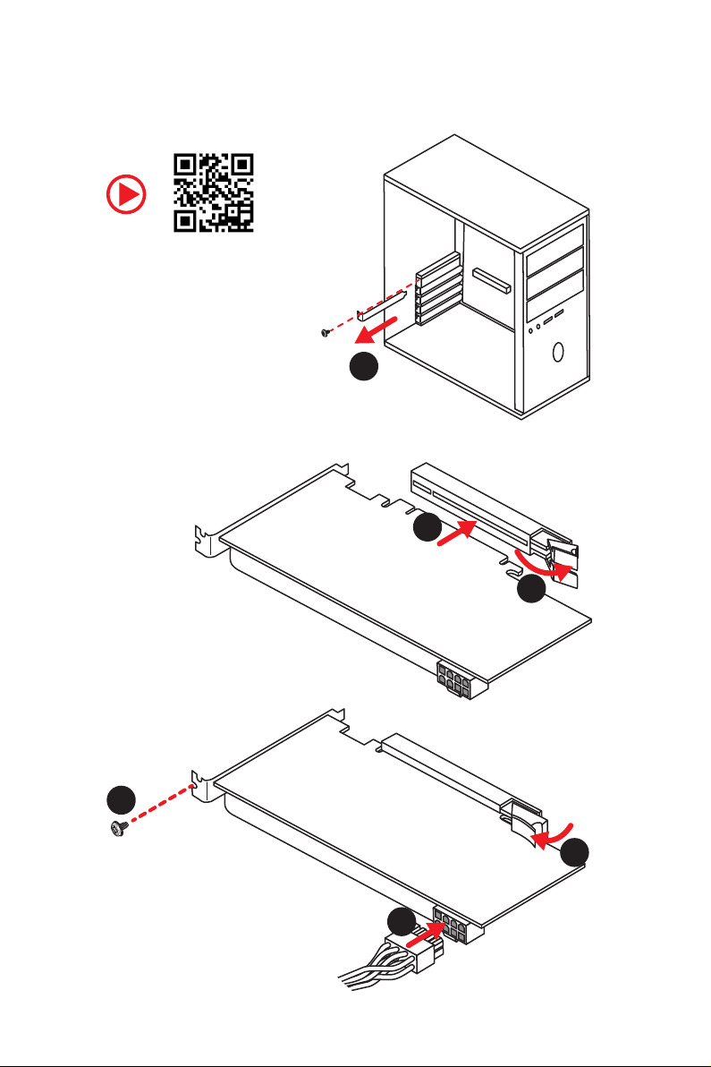
Installing a Graphics Card/ Einbau der Grafikkarte/ Installer
une carte graphique/ Установка дискретной видеокарты
1
3
2
5
4
6
Quick Start
VII
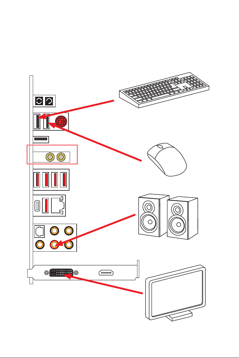
Connecting Peripheral Devices/ Peripheriegeräte/
Connecter un périphérique anschliessen/ Подключение
периферийных устройств
(Optional)
VIII
Quick Start
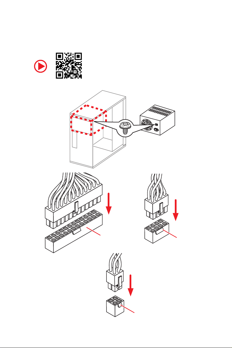
Connecting the Power Connectors/ Stromanschlüsse
anschliessen/ Connecter les câbles du module d’alimentation/
Подключение разъемов питания
ATX_PWR1
CPU_PWR2
CPU_PWR1
Quick Start
IX
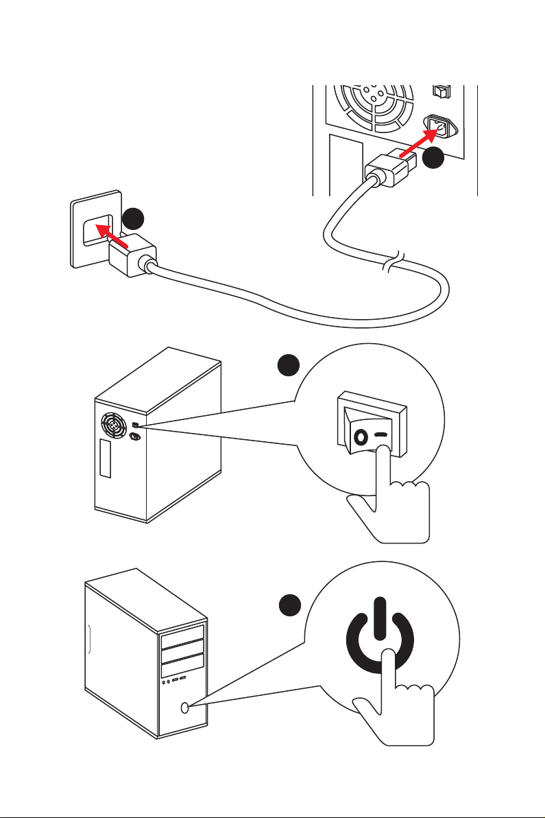
Power On/ Einschalten/ Mettre sous-tension/ Включение
питания
1
2
3
Quick Start
X
4

Contents
Safety Information ……………………………………………………………………………………. 2
Specifications …………………………………………………………………………………………… 3
Rear I/O Panel …………………………………………………………………………………………. 9
LAN Port LED Status Table…………………………………………………………………………. 9
Audio Ports Configuration ………………………………………………………………………….. 9
Realtek HD Audio Manager ………………………………………………………………………. 10
Installing Antennas (Optional) …………………………………………………………………… 12
Overview of Components ………………………………………………………………………… 13
CPU Socket …………………………………………………………………………………………….. 14
DIMM Slots ……………………………………………………………………………………………… 15
PCI_E1~6: PCIe Expansion Slots ……………………………………………………………….. 18
PCIe slots bandwidth table ……………………………………………………………………….. 18
U2_1: U.2 Connector ………………………………………………………………………………… 20
M2_1~2: M.2 Slots (Key M) ……………………………………………………………………….. 21
SATA1~8: SATA 6Gb/s Connectors …………………………………………………………….. 22
OC1: GAME BOOST Knob …………………………………………………………………………. 24
JSLOW1: Slow Mode Booting Jumper ………………………………………………………… 25
CPU_PWR1~2, ATX_PWR1: Power Connectors …………………………………………… 26
JFP1, JFP2: Front Panel Connectors …………………………………………………………. 27
JUSB1, JUSB3: USB 3.1 Gen1 Connectors………………………………………………….. 27
JUSB2: USB 3.1 Gen2 Type-C Connector ……………………………………………………. 28
JUSB4~5: USB 2.0 Connectors ………………………………………………………………….. 29
JTPM1: TPM Module Connector ………………………………………………………………… 29
CPU_FAN1, PUMP_FAN1, SYS_FAN1~4: Fan Connectors …………………………….. 30
VRAID1: Virtual RAID on CPU Connector ……………………………………………………. 30
JAUD1: Front Audio Connector ………………………………………………………………….31
JCI1: Chassis Intrusion Connector …………………………………………………………….. 31
BIOS_SW1: Multi-BIOS Switch ………………………………………………………………….. 32
JBAT1: Clear CMOS (Reset BIOS) Jumper ………………………………………………….. 33
POWER1, RESET1: Power Button, Reset Button …………………………………………. 33
JLED1: RGB LED connector ……………………………………………………………………… 34
LED light effect demonstration components ………………………………………………. 34
Onboard LEDs ………………………………………………………………………………………… 35
BIOS Setup …………………………………………………………………………………………….. 41
Software Description ………………………………………………………………………………. 56
Installing Windows® 10 …………………………………………………………………………….. 56
Installing Drivers …………………………………………………………………………………….. 56
Installing Utilities ……………………………………………………………………………………. 56
Contents
1

Safety Information
y The components included in this package are prone to damage from electrostatic
discharge (ESD). Please adhere to the following instructions to ensure successful
computer assembly.
y Ensure that all components are securely connected. Loose connections may cause
the computer to not recognize a component or fail to start.
y Hold the motherboard by the edges to avoid touching sensitive components.
y It is recommended to wear an electrostatic discharge (ESD) wrist strap when
handling the motherboard to prevent electrostatic damage. If an ESD wrist strap is
not available, discharge yourself of static electricity by touching another metal object
before handling the motherboard.
y Store the motherboard in an electrostatic shielding container or on an anti-static pad
whenever the motherboard is not installed.
y Before turning on the computer, ensure that there are no loose screws or metal
components on the motherboard or anywhere within the computer case.
y Do not boot the computer before installation is completed. This could cause
permanent damage to the components as well as injury to the user.
y If you need help during any installation step, please consult a certified computer
technician.
y Always turn off the power supply and unplug the power cord from the power outlet
before installing or removing any computer component.
y Keep this user guide for future reference.
y Keep this motherboard away from humidity.
y Make sure that your electrical outlet provides the same voltage as is indicated on the
PSU, before connecting the PSU to the electrical outlet.
y Place the power cord such a way that people can not step on it. Do not place anything
over the power cord.
y All cautions and warnings on the motherboard should be noted.
y If any of the following situations arises, get the motherboard checked by service
personnel:
Liquid has penetrated into the computer.
The motherboard has been exposed to moisture.
The motherboard does not work well or you can not get it work according to user
guide.
The motherboard has been dropped and damaged.
The motherboard has obvious sign of breakage.
y Do not leave this motherboard in an environment above 60°C (140°F), it may damage
the motherboard.
Safety Information
2

Specifications
CPU
Chipset Intel
Memory
Expansion Slots
LGA2066 Socket
supports up to 4-channels DDR4**
supports up to 2-channels DDR4**
* For the latest information about memory, please visit http://www.msi.com
** Please refer the DIMM Slots section for more details.
* Please refer to page 18 for PCIe 3.0 bandwidth table.
®
y Supports Intel
®
X299 Chipset
Core™ X-Series Processor Family for
y 8x DDR4 memory slots, support up to 128GB*
y Quad channel memory architecture with the CPU that
X-series processor support DDR4 4133(OC)/ 4000(OC)/
3866(OC)/ 3800(OC)/ 3733(OC)/ 3600(OC)/ 3466(OC)/
3400(OC)/ 3333(OC)/ 3200(OC)/ 3000(OC)/ 2933(OC)/
2800(OC)/ 2667/ 2400/ 2133 MHz*
y Dual channel memory architecture with the CPU that
X-series processor support DDR4 4500(OC)/ 4400(OC)/
4333(OC)/ 4266(OC)/ 4200(OC)/ 4133(OC)/ 4000(OC)/
3866(OC)/ 3800(OC)/ 3733(OC)/ 3600(OC)/ 3466(OC)/
3400(OC)/ 3333(OC)/ 3200(OC)/ 3000(OC)/ 2933(OC)/
2800(OC)/ 2667/ 2400/ 2133 MHz*
y Supports Intel
®
Extreme Memory Profile (XMP)
y 4x PCIe 3.0 x16 slots
Support x16/ x4/ x16/ x8 mode with the 44-lane CPU.*
Support x16/ x4/ x8/ x0, x8/ x4/ x8/ x8 modes with the
28-lane CPU.*
Support x8/ x0/ x8/ x0, x8/ x4/ x4/ x0 modes with the
16-lane CPU.*
y 2x PCIe 3.0 x1 slots
Multi-GPU
Audio
y Supports AMD
y Supports NVIDIA
y Realtek
y 7.1-Channel High Definition Audio
®
CrossFire™ Technology
®
SLI™ Technology
®
ALC1220 Codec
y Supports S/PDIF output
LAN 1x Intel I219-V Gigabit LAN controller
Continued on next page
Specifications
3

Wirsless LAN &
Bluetooth
®
(Optional)
Continued from previous page
®
Dual Band Wireless-AC 8265 module (optional)
y Intel
The Wireless module is pre-install in the M2_3 (Key-E)
slot.
Supports Wi-Fi 802.11 a/b/g/n/ac, dual band (2.4GHz,
5GHz) up to 867 Mbps speed.
Supports Dual Mode Bluetooth
®
2.1, 2.1+EDR, 3.0, 4.0,
BLE, 4.2
USB
Storage
y ASMedia
®
ASM3142 Chipset
1x USB 3.1 Gen2 (SuperSpeed USB 10Gbps) Type-A port
on the back panel
2x USB 3.1 Gen2 (Super Speed USB 10Gbps) Type-C
ports(1 port on the back panel, 1 port available through
the internal USB connector)
y ASMedia
®
ASM1074 HUB
3x USB 3.1 Gen1 (SuperSpeed USB) Type-A ports on the
back panel
®
y Intel
X299 Chipset
5x USB 3.1 Gen1 (SuperSpeed USB) ports (1 port on the
back panel, 4 ports available through the internal USB
connectors)
7x USB 2.0 (High-speed USB) ports (3 ports on the
back panel, 4 ports available through the internal USB
connectors)
®
Intel
X299 Chipset
y 8x SATA 6Gb/s ports*
y 2x M.2 slots (Key M)*
Supports up to PCIe 3.0 x4 and SATA 6Gb/s
M2_1 slot supports 2242/ 2260 /2280 storage devices
M2_2 slot supports 2242/ 2260 /2280/ 22110 storage
devices
®
Intel
Optane™ Memory Ready**
y 1x U.2 port *
Supports PCIe 3.0 x4 NVMe storage
y Supports Intel
* M.2 slots, U.2 port and SATA ports share the same bandwidth. Please refer to
page 22 for U.2, M.2 & SATA combination table.
** Please refer to the Intel
website.
***The functions will be supported depend on the CPU.
®
Smart Response Technology***
®
Optane™ Memory Configuration Guide on MSI
Specifications
4
Continued on next page

RAID
Internal Connectors
Continued from previous page
®
X299 Chipset
Intel
y Supports RAID 0, RAID 1, RAID 5 and RAID 10 for SATA
storage devices
y Supports RAID 0 and RAID 1 for M.2 storage devices*
* M.2 PCIe RAID volume can be created with M.2/Optane Genie.
y 1x 24-pin ATX main power connector
y 1x 8-pin ATX 12V power connector
y 1x 4-pin ATX 12V power connector
y 8x SATA 6Gb/s connectors
y 3x M.2 slots (Key M x2, Key E x1)
y 1x U.2 port
y 2x USB 2.0 connectors (supports additional 4 USB 2.0
ports)
y 2x USB 3.1 Gen1 connectors (supports additional 4 USB 3.1
Gen1 ports)
y 1x USB 3.1 Gen2 Type-C port
y 1x 4-pin CPU fan connector
y 1x 4-pin Water Pump connector
y 4x 4-pin system fan connectors
y 1x Front panel audio connector
y 2x Front panel connectors
y 1x TPM module connector
y 1x Chassis Intrusion connector
y 1x Clear CMOS jumper
y 1x Slow mode booting jumper
y 1x GAME BOOST knob
y 1x Power button
y 1x Reset button
y 1x Multi-BIOS switch
y 1x RGB LED connector
y 1x Virtual RAID on CPU connector
Continued on next page
Specifications
5

Continued from previous page
y 1x Clear CMOS button
y 1x BIOS FLASHBACK+ button
y 1x PS/2 keyboard/ mouse combo port
y 3x USB 2.0 Type-A ports
Back Panel
Connectors
I/O Controller NUVOTON NCT6795 Controller Chip
Hardware Monitor
y 2x Wi-Fi Antenna connectors (optional)
y 4x USB 3.1 Gen1 Type-A ports
y 1x LAN (RJ45) port
y 1x USB 3.1 Gen2 Type-A port
y 1x USB 3.1 Gen2 Type-C port
y 1x Optical S/PDIF OUT connector
y 5x OFC audio jacks
y CPU/System temperature detection
y CPU/System fan speed detection
y CPU/System fan speed control
Form Factor
BIOS Features
Specifications
6
y ATX Form Factor
y 12 in. x 9.6 in. (30.5 cm x 24.4 cm)
y 2x 128 Mb flash
y UEFI AMI BIOS
y ACPI 6.0, PnP 1.0a, SM BIOS 3.0
y Multi-language
Continued on next page

Software
Continued from previous page
y Drivers
y APP MANAGER
y SUPER CHARGER
y COMMAND CENTER
y LIVE UPDATE 6
y MSI SMART TOOL
y DRAGON EYE
y GAMING APP
y X-BOOST
y MYSTIC LIGHT
y RAMDISK
y GAMING LAN Manager
y FAST BOOT
y Nahimic Audio
y XSplit Gamecaster V2
y Tridef VR & Smart Cam
y SteelSeries Engine 3
y WTFast*
y CPU-Z MSI GAMING
®
y Intel
Extreme Tuning Utility
y Google Chrome
y Norton
* This offer is valid for a limited period only, for more information please visit
www.msi.com
™
,Google Toolbar, Google Drive
™
Internet Security Solution
MSI Special
Features
y Audio Boost 4
y Nahimic 2
y GAMING LAN with Gaming LAN Manager
y Intel WiFi (Optional)
y Turbo U.2
y Twin Turbo M.2
y Pump Fan
y Smart Fan Control
Continued on next page
Specifications
7

MSI Special
Features
Continued from previous page
y Mystic Light
y Mystic Light Extension
y Mystic light SYNC
y EZ DEBUG LED
y DDR4 Steel Armor
y M.2 Shield
y PCI-E Steel Armor
y U.2 Steel Armor
y VR Cover
y Muitl GPU — SLI Technology
y Muitl GPU — CrossFire Technology
y DDR4 Boost
y GAME Boost
y OC Engine
y USB with Type A+C
y Lightning USB
y Front Lightning USB
y Military Class 5
y 7000+ Quality Test
y VR Boost
y VR Ready
y GAMING HOTKEY
y GAMING MOUSE Control
y Click BIOS 5
y BIOS FLASHBACK+
y Dual BIOS
y Quadro SLI Ready
y Quadro Ready
y GAMING Certified
y SteelSeries Certified
Specifications
8
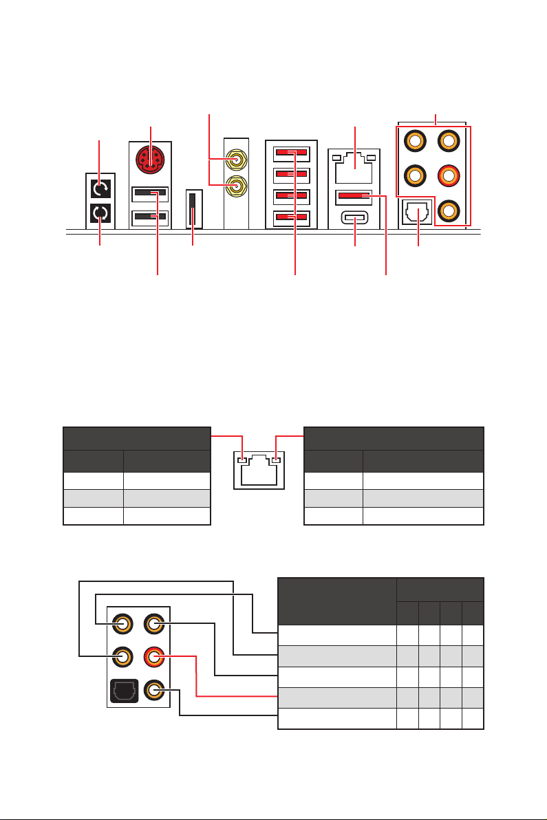
Rear I/O Panel
Wi-Fi Antenna
connectors (Optional)
Clear CMOS
button
PS/2
LAN
Audio Ports
BIOS FLASHBACK+
button
USB 2.0/
BIOS FLASHBACK+
USB 2.0
USB 3.1 Gen2
Type-C
USB 3.1 Gen1
Type-A
Optical
S/PDIF-Out
USB 3.1 Gen2
Type-A
y Clear CMOS button — Power off your computer. Press and hold the Clear CMOS
button for about 5-10 seconds to reset BIOS to default values.
y BIOS FLASHBACK+ port/ button — Please refer to page 43 for Updating BIOS with
BIOS FLASHBACK+.
LAN Port LED Status Table
Link/ Activity LED
Status Description
Off No link
Yellow Linked
Blinking Data activity
Speed LED
Status Description
Off 10 Mbps connection
Green 100 Mbps connection
Orange 1 Gbps connection
Audio Ports Configuration
Audio Ports
Center/ Subwoofer Out ● ●
Rear Speaker Out ● ● ●
Line-In/ Side Speaker Out ●
Line-Out/ Front Speaker Out ● ● ● ●
Mic In
(●: connected, Blank: empty)
2 4 6 8
Channel
Rear I/O Panel
9

Realtek HD Audio Manager
After installing the Realtek HD Audio driver, the Realtek HD Audio Manager icon will
appear in the system tray. Double click on the icon to launch.
Device
Selection
Advanced
Settings
Application
Enhancement
Main Volume
Profiles
Jack Status
Connector
Strings
y Device Selection — allows you to select a audio output source to change the related
options. The check sign indicates the devices as default.
y Application Enhancement — the array of options will provide you a complete guidance
of anticipated sound effect for both output and input device.
y Main Volume — controls the volume or balance the right/left side of the speakers that
you plugged in front or rear panel by adjust the bar.
y Profiles — toggles between profiles.
y Advanced Settings — provides the mechanism to deal with 2 independent audio
streams.
y Jack Status — depicts all render and capture devices currently connected with your
computer.
y Connector Settings — configures the connection settings.
Auto popup dialog
When you plug into a device at an audio jack, a dialogue window will pop up asking you
which device is current connected.
Each jack corresponds to its default setting as shown on the next page.
Rear I/O Panel
10
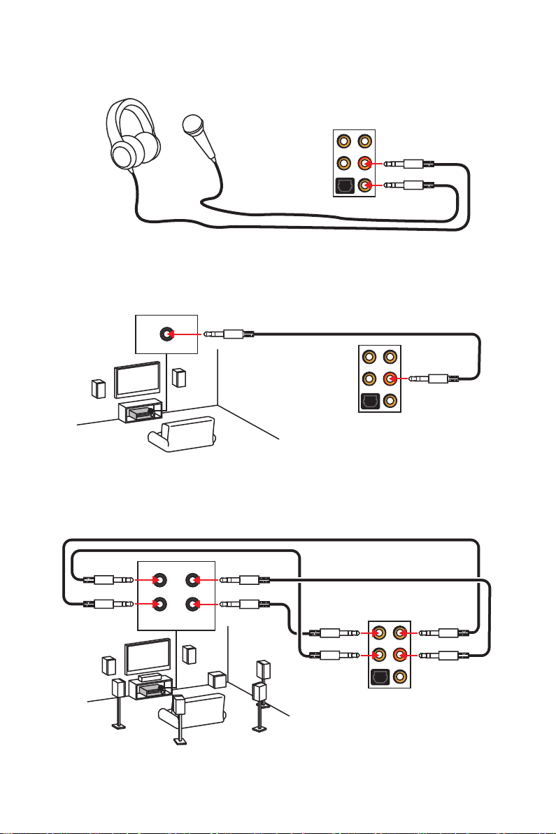
Audio jacks to headphone and microphone diagram
Audio jacks to stereo speakers diagram
AUDIO INPUT
Audio jacks to 7.1-channel speakers diagram
AUDIO INPUT
Rear Front
Side Center/
Subwoofer
Rear I/O Panel
11
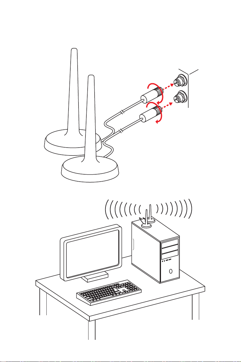
Installing Antennas (Optional)
1. Screw the antennas tight to the Wi-Fi antenna connectors as shown.
2. Place the antennas as high as possible.
Rear I/O Panel
12
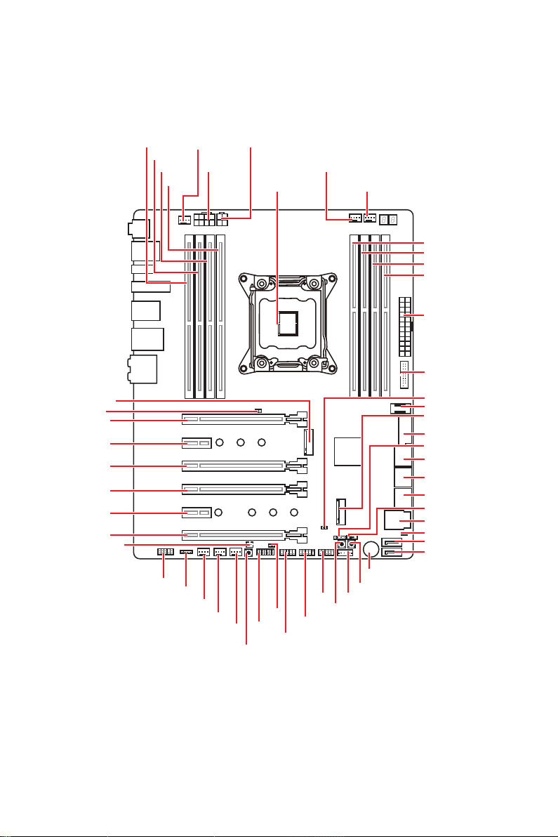
Overview of Components
M2_1
JBAT1
PCI_E1
PCI_E2
PCI_E3
PCI_E4
PCI_E5
PCI_E6
JPWRLED1
DIMMB1
DIMMB2
DIMMA1
JAUD1
CPU_FAN1
DIMMA2
JLED1
SYSFAN4
CPU_PWR2
CPU_PWR1
SYSFAN3
SYSFAN2
DEMOLED1
CPU Socket
JSEL1
JTPM1
JFP1
PUMP_FAN1
POWER1
JUSB5
SYS_FAN1
RESET1
VRAID1JUSB4
OC1
DIMMC2
DIMMC1
DIMMD2
DIMMD1
ATX_PWR1
JUSB1
JCI1
JUSB2
M2_2
JUSB3
JFP2
SATA▼1▲2
SATA▼3▲4
SATA▼5▲6
BIOS_SW1
U2_1
JSLOW1
SATA7
SATA8
Overview of Components
13
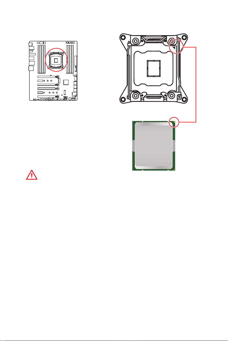
CPU Socket
Introduction to the LGA 2066 CPU
The surface of the LGA2066 CPU has
four alignment keys and a yellow triangle
to assist in correctly lining up the CPU
for motherboard placement. The yellow
triangle is the Pin 1 indicator.
Important
y
Always unplug the power cord from the power outlet before installing or removing
the CPU.
y
Please retain the CPU protective cap after installing the processor. MSI will deal with
Return Merchandise Authorization (RMA) requests if only the motherboard comes with
the protective cap on the CPU socket.
y
When installing a CPU, always remember to install a CPU heatsink. A CPU heatsink
is necessary to prevent overheating and maintain system stability.
y
Confirm that the CPU heatsink has formed a tight seal with the CPU before booting
your system.
y
Overheating can seriously damage the CPU and motherboard. Always make sure
the cooling fans work properly to protect the CPU from overheating. Be sure to apply
an even layer of thermal paste (or thermal tape) between the CPU and the heatsink to
enhance heat dissipation.
y
Whenever the CPU is not installed, always protect the CPU socket pins by covering
the socket with the plastic cap.
y
If you purchased a separate CPU and heatsink/ cooler, Please refer to the
documentation in the heatsink/ cooler package for more details about installation.
y
This motherboard is designed to support overclocking. Before attempting to
overclock, please make sure that all other system components can tolerate
overclocking. Any attempt to operate beyond product specifications is not
recommended. MSI
operation beyond product specifications.
®
does not guarantee the damages or risks caused by inadequate
Overview of Components
14
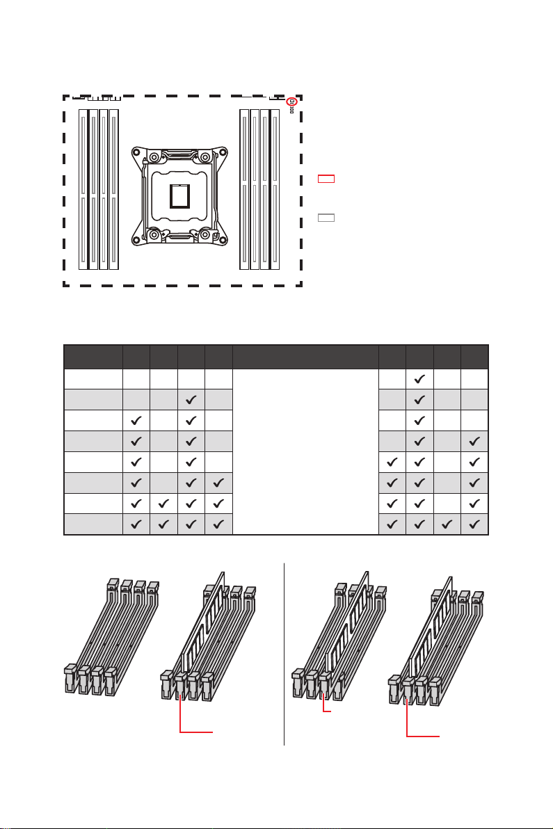
DIMM Slots
S/K LED : S/K LED indicates that
the installed CPU supports either
4-channels or 2-channels memory
architecture.
Red = 8 DIMMs support
(4-channels architecture CPU)
White = 4 DIMMs support
(2-channels architecture CPU)
B1B2A1A2 C2C1D2D1
Memory module installation recommendation (4-Channels architecture CPU )
B1 B2 A1 A2 Intel Core X-series CPU C2 C1 D2 D1
1 DIMM
2 DIMMs
3 DIMMs
4 DIMMs
5 DIMMs
6 DIMMs
7 DIMMs
8 DIMMs
Supports 4-channels
memory architecture
DIMMC1
DIMMA1
DIMMC1
Overview of Components
15
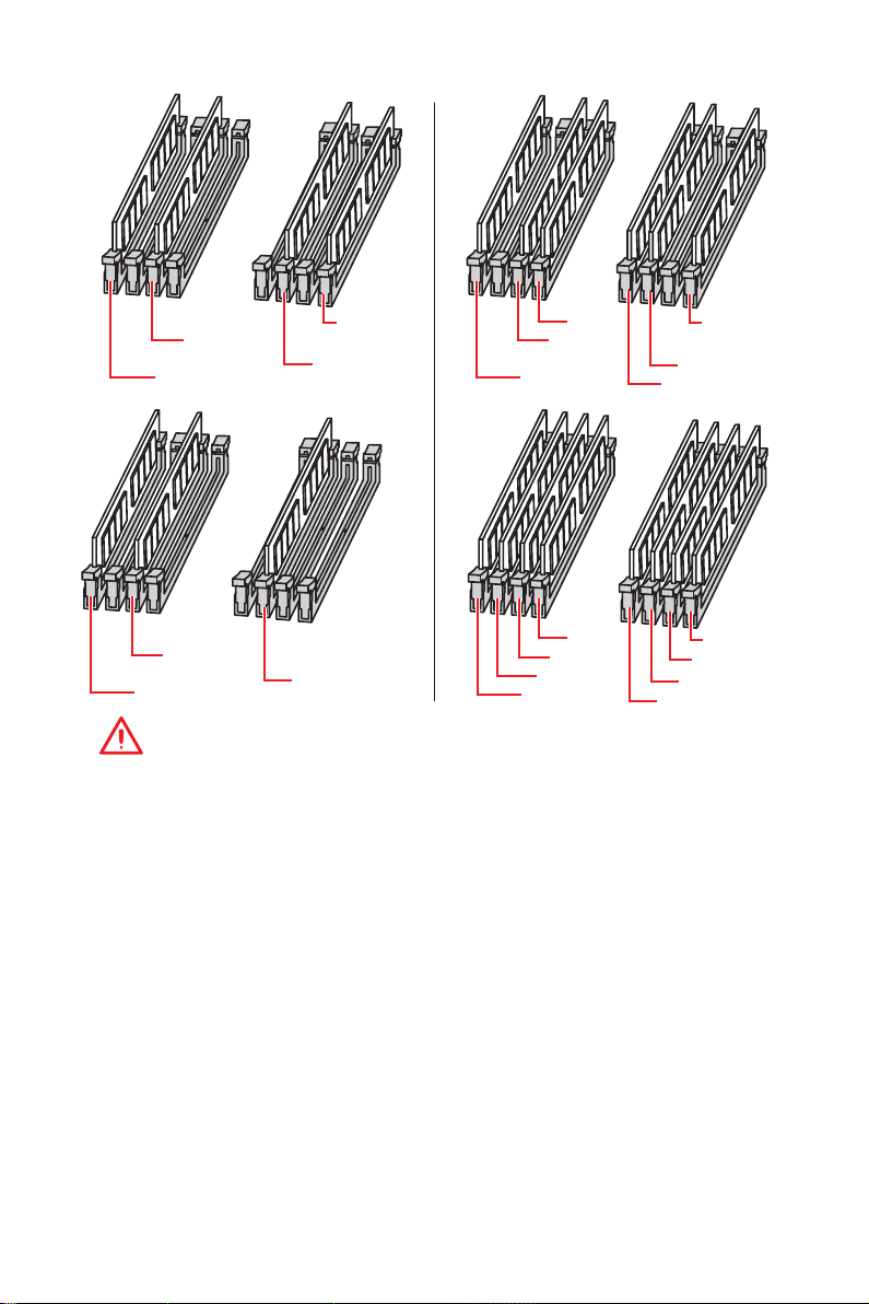
DIMMA1
DIMMB1
DIMMD1
DIMMC1
DIMMA1
DIMMB1
DIMMA2
DIMMD1
DIMMC1
DIMMC2
DIMMA1
DIMMB1
DIMMC1
DIMMA1
DIMMB2
DIMMB1
DIMMA2
DIMMC2
Important
y
Always insert a memory module in the DIMMC1 slot first.
y
To ensure system stability for Dual/ Triple/ Quad channel mode, memory modules
must be of the same type, number and density. And for every channel, the odd number
DIMM slot must to be installed first.
y
Due to chipset resource usage, the available capacity of memory will be a little less
than the amount of installed.
y
Based on Intel CPU specification, the Memory DIMM voltage below 1.35V is
suggested to protect the CPU.
y
Please note that the maximum capacity of addressable memory is 4GB or less
for 32-bit Windows OS due to the memory address limitation. Therefore, we
recommended that you to install 64-bit Windows OS if you want to install more than
4GB memory on the motherboard.
y
Some memory may operate at a lower frequency than the marked value when
overclocking due to the memory frequency operates dependent on its Serial Presence
Detect (SPD).
y
It is recommended to use a more efficient memory cooling system for full DIMMs
installation or overclocking.
y
The stability and compatibility of installed memory modules depend on installed CPU
and devices when overclocking.
Overview of Components
16
DIMMD1
DIMMD2
DIMMC1
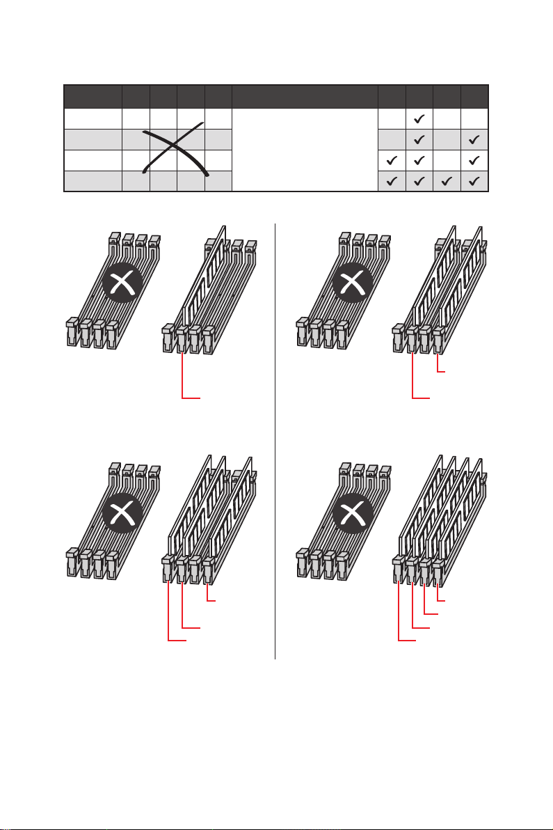
Memory module installation recommendation (2-Channels architecture CPU )
B1 B2 A1 A2 Intel Core X-series CPU C2 C1 D2 D1
1 DIMM
2 DIMMs
3 DIMMs
4 DIMMs
DIMMB1, B2, A1 and A2 are un-available
DIMMC1 DIMMC1
Supports 2-channels
memory architecture
DIMMD1
DIMMD1 DIMMD1
DIMMC1 DIMMC1
DIMMC2 DIMMC2
Overview of Components
DIMMD2
17
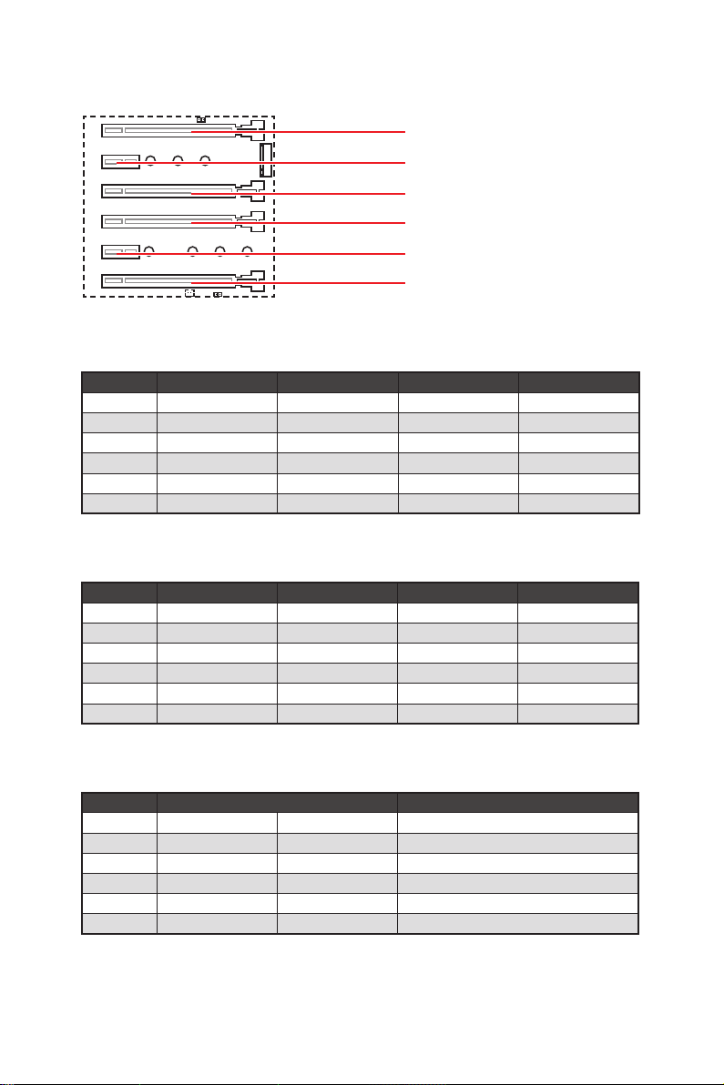
PCI_E1~6: PCIe Expansion Slots
PCI_E1: PCIe 3.0 x16
PCI_E2: PCIe 3.0 x1
PCI_E3: PCIe 3.0 x4
PCI_E4: PCIe 3.0 x16
PCI_E5: PCIe 3.0 x1
PCI_E6: PCIe 3.0 x8
PCIe slots bandwidth table
for 44-lane CPU
Graphics Card Single 2-Way* 2-Way 3-Way*
PCI_E1 @ 3.0 x16 @ 3.0 x16 @ 3.0 x16 @ 3.0 x16
PCI_E2 3.0 x1 3.0 x1 3.0 x1 3.0 x1
PCI_E3 3.0 x4 3.0 x4 3.0 x4 3.0 x4
PCI_E4 3.0 x16 @ 3.0 x16 3.0 x16 @ 3.0 x16
PCI_E5 3.0 x1 3.0 x1 3.0 x1 3.0 x1
PCI_E6 3.0 x8 3.0 x8 @ 3.0 x8 @ 3.0 x8
(@: graphics card slot, *: best combination)
for 28-lane CPU
Graphics Card Single 2-Way* 2-Way 3-Way
PCI_E1 @ 3.0 x16 @ 3.0 x16 @ 3.0 x8 @ 3.0 x8
PCI_E2 3.0 x1 3.0 x1 3.0 x1 3.0 x1
PCI_E3 3.0 x4 3.0 x4 3.0 x4 3.0 x4
PCI_E4 3.0 x8 @ 3.0 x8 3.0 x8 @ 3.0 x8
PCI_E5 3.0 x1 3.0 x1 3.0 x1 3.0 x1
PCI_E6 Empty Empty @ 3.0 x8 @ 3.0 x8
(@: graphics card slot, *: best combination)
for 16-lane CPU
Graphics Card Single 2-Way
PCI_E1 @ 3.0 x8 @ 3.0 x8 @ 3.0 x8
PCI_E2 3.0 x1 3.0 x1 3.0 x1
PCI_E3 Empty 3.0 x4 Empty
PCI_E4 3.0 x8 3.0 x4 @ 3.0 x8
PCI_E5 3.0 x1 3.0 x1 3.0 x1
PCI_E6 ─ ─ ─
(@: graphics card slot, ─: unavailable)
Overview of Components
18
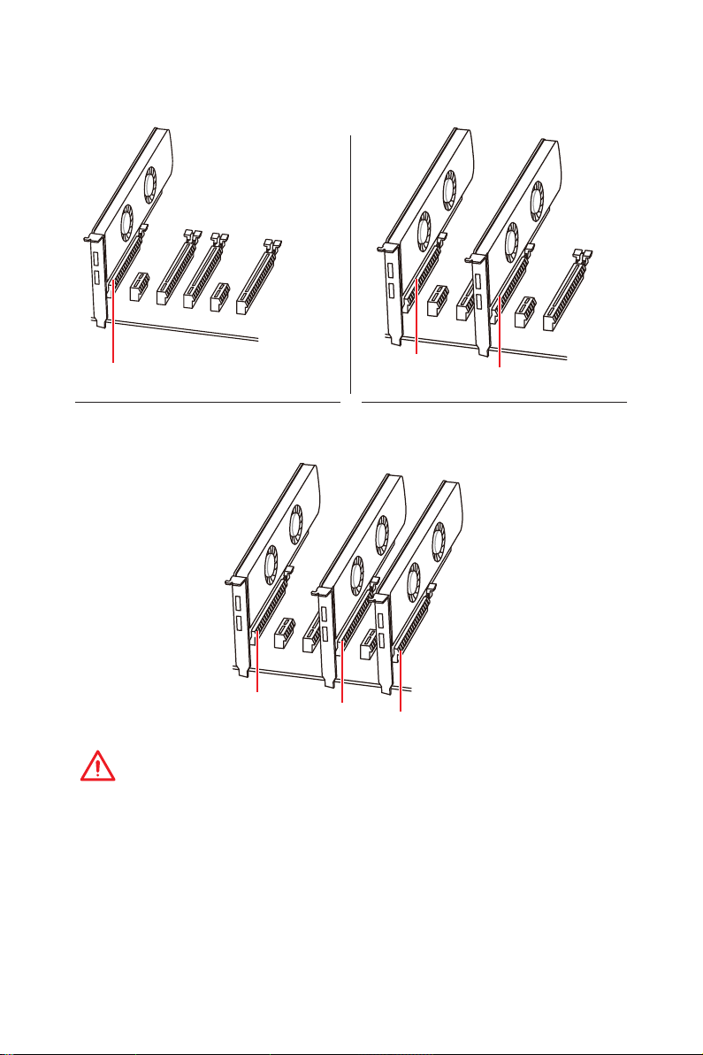
Multiple graphics cards installation recommendation
PCI_E1
For 44- & 28-lane CPU
PCI_E1
PCI_E4
PCI_E1
PCI_E4
PCI_E6
Important
y
If you install a large and heavy graphics card, you need to use a tool such as MSI
Gaming Series Graphics Card Bolster to support its weight and to prevent deformation
of the slot.
y
For a single PCIe x16 expansion card installation with optimum performance, using
the PCI_E1 slot is recommended.
y
When adding or removing expansion cards, always turn off the power supply and
unplug the power supply power cable from the power outlet. Read the expansion
card’s documentation to check for any necessary additional hardware or software
changes.
Overview of Components
19
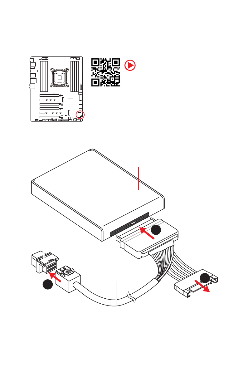
U2_1: U.2 Connector
This connector is a U.2 interface port. Each connector can connect to one PCIe 3.0 x4
NVMe storage device.
Video Demonstration
Watch the video to learn how to Install
U.2 SSD.
Installing U.2 SSD
1. Connect the U.2 cable to the U.2 connector on the
motherboard.
2. Connect the U.2 cable to the U.2 SSD.
3. Connect the U.2 cable to power adapter cable.
U.2 SSD
U.2 Connector
1
Overview of Components
20
U.2 Cable
2
3
Connect to power
adapter cable
Loading…
I
Quick Start
Quick Start
Thank you for purchasing the MSI
®
X299 GAMING PRO CARBON/
X299 GAMING PRO CARBON AC motherboard. This Quick Start
section provides demonstration diagrams about how to install
your computer. Some of the installations also provide video
demonstrations. Please link to the URL to watch it with the web
browser on your phone or tablet. You may have even link to the URL
by scanning the QR code.
Kurzanleitung
Danke, dass Sie das MSI
®
X299 GAMING PRO CARBON/ X299
GAMING PRO CARBON AC Motherboard gewählt haben. Dieser
Abschnitt der Kurzanleitung bietet eine Demo zur Installation
Ihres Computers. Manche Installationen bieten auch die
Videodemonstrationen. Klicken Sie auf die URL, um diese
Videoanleitung mit Ihrem Browser auf Ihrem Handy oder Table
anzusehen. Oder scannen Sie auch den QR Code mit Ihrem Handy,
um die URL zu öffnen.
Présentation rapide
Merci d’avoir choisi la carte mère MSI
®
X299 GAMING PRO CARBON/
X299 GAMING PRO CARBON AC. Ce manuel fournit une rapide
présentation avec des illustrations explicatives qui vous aideront à
assembler votre ordinateur. Des tutoriels vidéo sont disponibles pour
certaines étapes. Cliquez sur le lien fourni pour regarder la vidéo sur
votre téléphone ou votre tablette. Vous pouvez également accéder au
lien en scannant le QR code qui lui est associé.
Быстрый старт
Благодарим вас за покупку материнской платы MSI
®
X299
GAMING PRO CARBON/ X299 GAMING PRO CARBON AC. В этом
разделе представлена информация, которая поможет
вам при сборке комьютера. Для некоторых этапов
сборки имеются видеоинструкции. Для просмотра видео,
необходимо открыть соответствующую ссылку в веб—
браузере на вашем телефоне или планшете. Вы также
можете выполнить переход по ссылке, путем сканирования
QR-кода.
-
MSI X299 GAMING PRO CARBON Operation & user’s manual (132 pages)
-
MSI X299 GAMING PRO CARBON Quick start manual (248 pages)
MSI X299 GAMING PRO CARBON Manuals come in various types, each serving a specific purpose to help users effectively operate and maintain their devices. Each type of MSI X299 GAMING PRO CARBON instruction is designed to address specific needs, ensuring users have the necessary information to use, maintain, and repair their devices effectively.
Related Instructions for MSI X299 GAMING PRO CARBON:
MS-7510, MPG Z490M GAMING EDGE WIFI, 760GA-P43 FX, 865PE NEO2-LS — Motherboard — ATX, MPG GAMING PLUS Z390
- MSI MS-7510
- MSI MPG Z490M GAMING EDGE WIFI
- MSI 760GA-P43 FX
- MSI 865PE NEO2-LS — Motherboard — ATX
- MSI MPG GAMING PLUS Z390
- MSI Z77A-GD55
- MSI Z77A
- MSI MS-7320
- MSI K8T Neo2-F
- MSI MPG B550 GAMING CARBON WIFI
- MSI 694D Pro2
- MSI MS-6799
Motherboard Devices by Other Brands:
| Brand | Device Model | Type of Document | Pages | Size | Views | Downloads | Updated |
|---|---|---|---|---|---|---|---|
| VICOR |
PI3741-0x-EVAL1 |
VICOR PI3741-0x-EVAL1 Operation & user’s manual |
9 | 1179 | 225 | 04-02-2025 | |
| Altera |
EP2AGX45 |
Altera EP2AGX45 Device handbook |
144 | 396 | 64 | 04-10-2024 | |
| Gigabyte |
GA-Z77-HD3 |
Gigabyte GA-Z77-HD3 Operation & user’s manual |
104 | 33.69 Mb | 1350 | 284 | 18-10-2024 |
| Gigabyte |
6BMM |
Gigabyte 6BMM Operation & user’s manual |
24 | 0.3 Mb | 439 | 80 | 27-02-2025 |
| DFI |
865PE-ML |
DFI 865PE-ML Operation & user’s manual |
116 | 857 | 146 | 02-11-2024 |
Categories:
Pci cards
Pcs
Indoor Furnishing
Keyboard
Kitchen Appliances
Mainboard