
Quick Start
Thank you for purchasing the MSI® X570-A PRO motherboard. This Quick Start
section provides demonstration diagrams about how to install your computer. Some
of the installations also provide video demonstrations. Please link to the URL to watch
it with the web browser on your phone or tablet. You may have even link to the URL by
scanning the QR code.
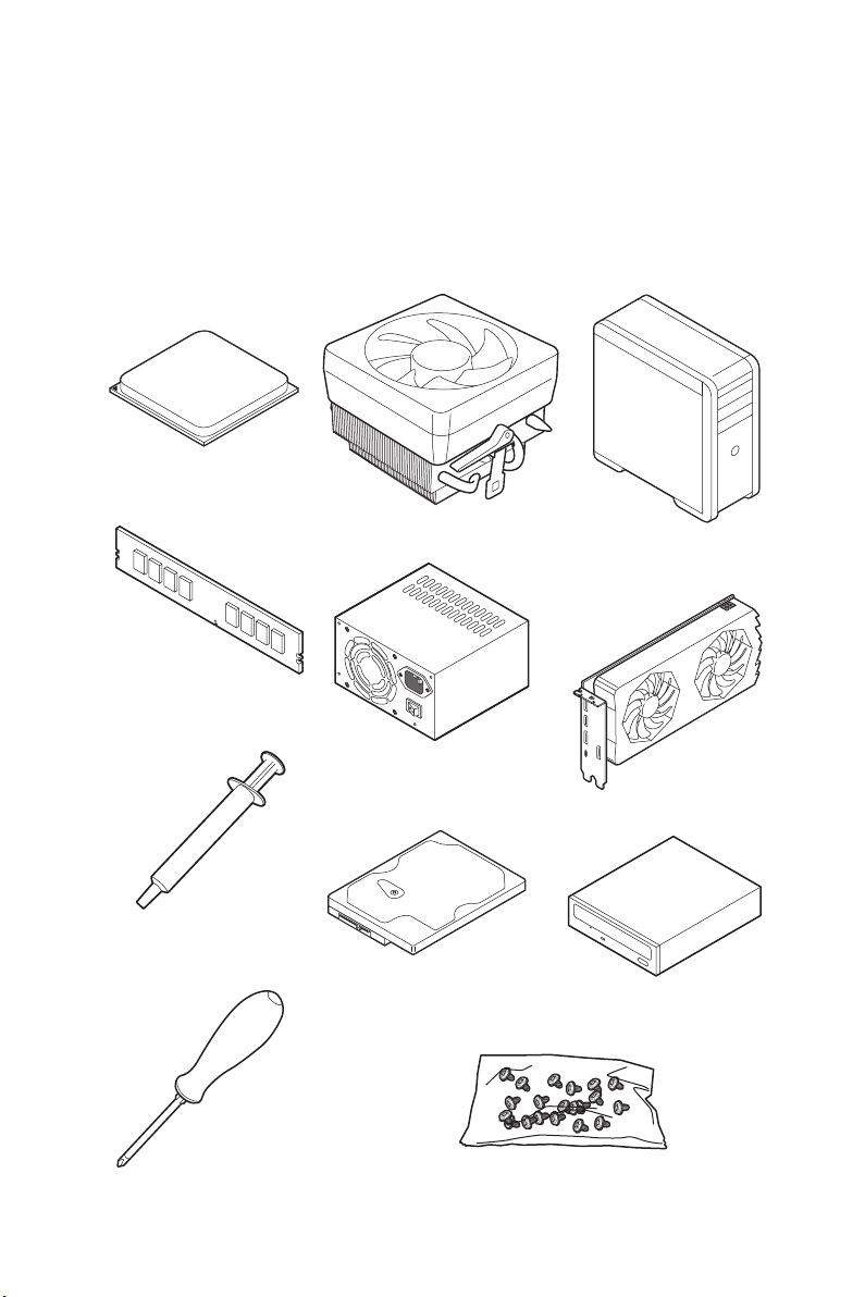
Preparing Tools and Components
AMD® AM4 CPU
CPU Fan
Chassis
DDR4 Memory
Thermal Paste
Phillips Screwdriver
Power Supply Unit
SATA Hard Disk Drive
Graphics Card
SATA DVD Drive
A Package of Screws
Quick Start
1

Safety Information
y The components included in this package are prone to damage from electrostatic
discharge (ESD). Please adhere to the following instructions to ensure successful
computer assembly.
y Ensure that all components are securely connected. Loose connections may cause
the computer to not recognize a component or fail to start.
y Hold the motherboard by the edges to avoid touching sensitive components.
y It is recommended to wear an electrostatic discharge (ESD) wrist strap when
handling the motherboard to prevent electrostatic damage. If an ESD wrist strap is
not available, discharge yourself of static electricity by touching another metal object
before handling the motherboard.
y Store the motherboard in an electrostatic shielding container or on an anti-static pad
whenever the motherboard is not installed.
y Before turning on the computer, ensure that there are no loose screws or metal
components on the motherboard or anywhere within the computer case.
y Do not boot the computer before installation is completed. This could cause
permanent damage to the components as well as injury to the user.
y If you need help during any installation step, please consult a certified computer
technician.
y Always turn off the power supply and unplug the power cord from the power outlet
before installing or removing any computer component.
y Keep this user guide for future reference.
y Keep this motherboard away from humidity.
y Make sure that your electrical outlet provides the same voltage as is indicated on the
PSU, before connecting the PSU to the electrical outlet.
y Place the power cord such a way that people can not step on it. Do not place anything
over the power cord.
y All cautions and warnings on the motherboard should be noted.
y If any of the following situations arises, get the motherboard checked by service
personnel:
Liquid has penetrated into the computer.
The motherboard has been exposed to moisture.
The motherboard does not work well or you can not get it work according to user
guide.
The motherboard has been dropped and damaged.
The motherboard has obvious sign of breakage.
y Do not leave this motherboard in an environment above 60°C (140°F), it may damage
the motherboard.
Quick Start
2
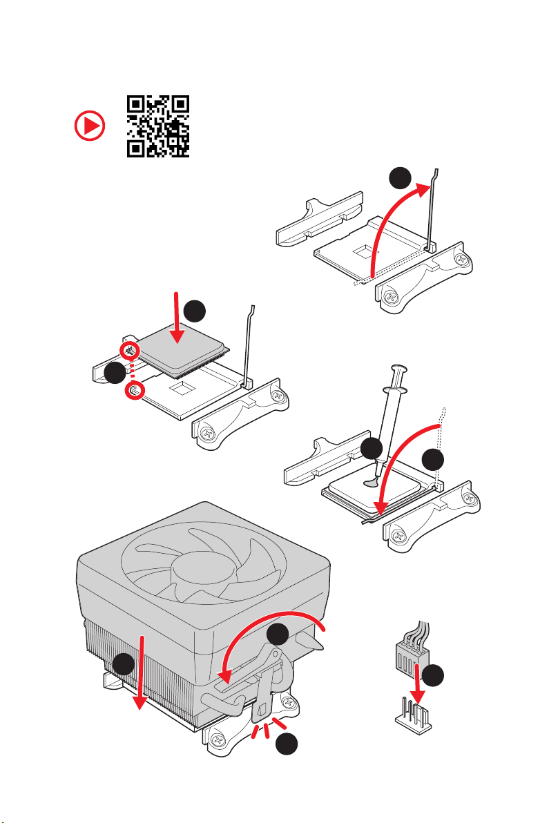
Installing a Processor
3
2
1
5
4
8
6
9
7
Quick Start
3
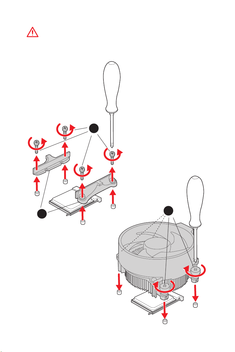
Important
If you are installing the screw-type CPU heatsink, please follow the figure below to
remove the retention module first and then install the heatsink.
1
Quick Start
4
2
3
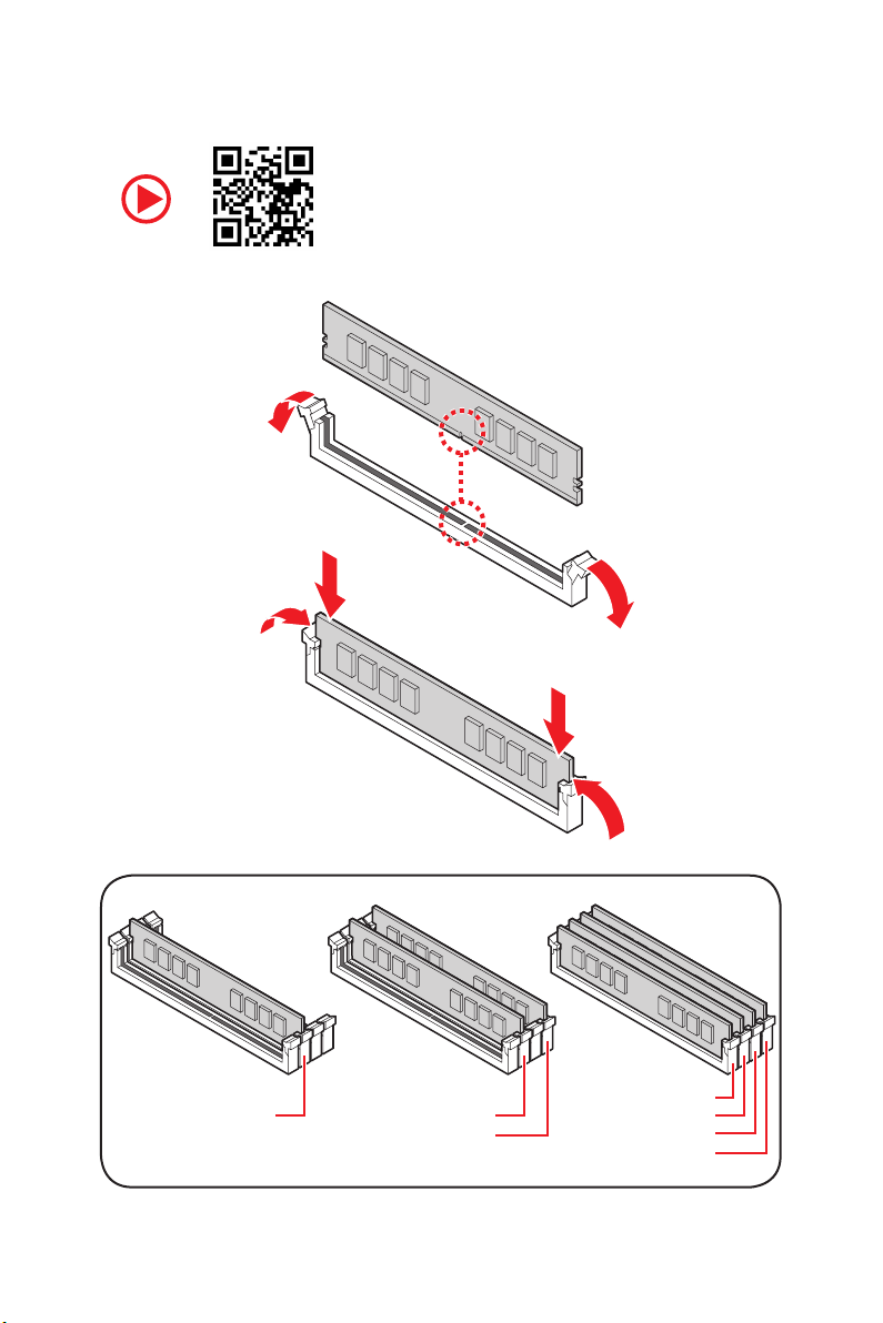
Installing DDR4 memory
DIMMA2 DIMMA2
DIMMB2
DIMMA1
DIMMA2
DIMMB1
DIMMB2
Quick Start
5
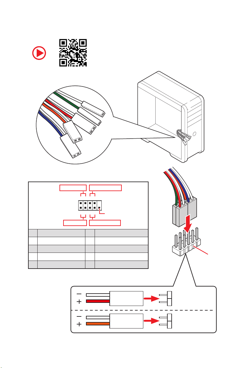
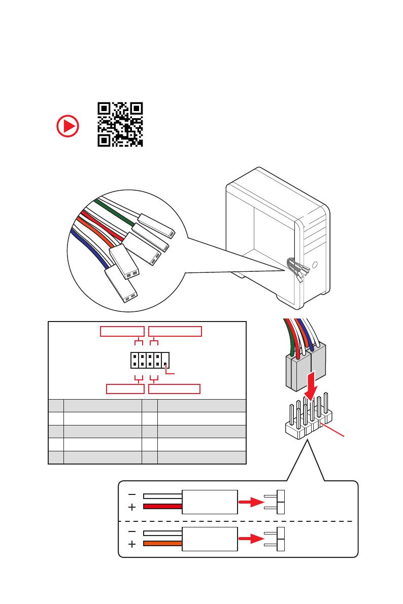
Connecting the Front Panel Header
RESET SW
POWER SW
POWER LED+
POWER LED-
HDD LED
Power LED
JFP1
Power Switch
+++—
——
2 10
1
—
+
HDD LED Reset Switch
1 HDD LED + 2 Power LED +
3 HDD LED — 4 Power LED —
5 Reset Switch 6 Power Switch
7 Reset Switch 8 Power Switch
9 Reserved 10 No Pin
Quick Start
6
9
Reserved
HDD LED
POWER LED
RESET SW
HDD LED
JFP1
HDD LED HDD LED +
POWER LED POWER LED +
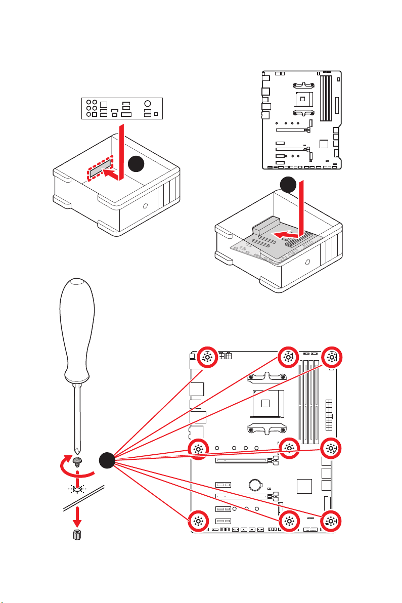
Installing the Motherboard
1
2
3
BAT1
Quick Start
7
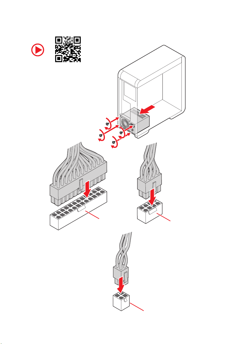
Connecting the Power Connectors
Quick Start
8
ATX_PWR1
CPU_PWR1
CPU_PWR2
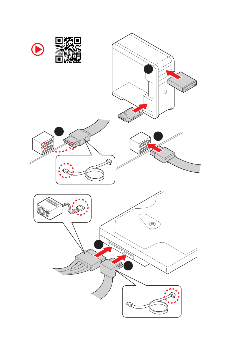
Installing SATA Drives
2
1
3
5
4
Quick Start
9
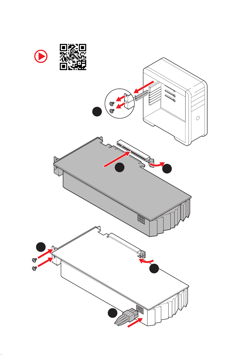
Installing a Graphics Card
1
3
2
5
4
6
10
Quick Start
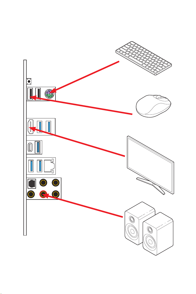
Connecting Peripheral Devices
Processor with integrated graphics
Quick Start
11
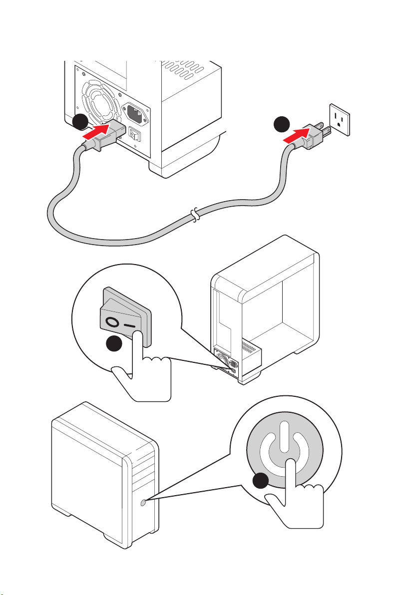
Power On
1
2
3
12
4
Quick Start

Contents
Quick Start ………………………………………………………………………………………………. 1
Preparing Tools and Components ……………………………………………………………….. 1
Safety Information …………………………………………………………………………………….. 2
Installing a Processor ………………………………………………………………………………… 3
Installing DDR4 memory ……………………………………………………………………………. 5
Connecting the Front Panel Header …………………………………………………………….. 6
Installing the Motherboard …………………………………………………………………………. 7
Connecting the Power Connectors ………………………………………………………………. 8
Installing SATA Drives………………………………………………………………………………… 9
Installing a Graphics Card ………………………………………………………………………… 10
Connecting Peripheral Devices …………………………………………………………………. 11
Power On………………………………………………………………………………………………… 12
Specifications …………………………………………………………………………………………. 15
Package contents …………………………………………………………………………………… 20
Block Diagram ………………………………………………………………………………………. 21
Rear I/O Panel ……………………………………………………………………………………….. 22
LAN Port LED Status Table……………………………………………………………………….. 22
Audio Ports Configuration ………………………………………………………………………… 22
Realtek Audio Console …………………………………………………………………………….. 23
Overview of Components ………………………………………………………………………… 25
CPU Socket …………………………………………………………………………………………….. 27
DIMM Slots ……………………………………………………………………………………………… 28
PCI_E1~5: PCIe Expansion Slots ……………………………………………………………….. 29
M2_1~2: M.2 Slots (Key M) ……………………………………………………………………….. 30
SATA1~6: SATA 6Gb/s Connectors …………………………………………………………….. 31
JFP1, JFP2: Front Panel Connectors …………………………………………………………. 31
CPU_PWR1~2, ATX_PWR1: Power Connectors …………………………………………… 32
CPU_FAN1, PUMP_FAN1, SYS_FAN1~4: Fan Connectors …………………………….. 33
JUSB3~4: USB 3.2 Gen1 Connectors …………………………………………………………. 34
JUSB1~2: USB 2.0 Connectors ………………………………………………………………….. 34
JAUD1: Front Audio Connector ………………………………………………………………….35
JCOM1: Serial Port Connector ………………………………………………………………….. 35
JCI1: Chassis Intrusion Connector …………………………………………………………….. 36
JBAT1: Clear CMOS (Reset BIOS) Jumper ………………………………………………….. 37
EZ Debug LED …………………………………………………………………………………………. 37
Contents
13

JRGB1~2: RGB LED connectors ………………………………………………………………… 38
JRAINBOW1~2: Addressable RGB LED connectors ……………………………………… 39
Installing OS, Drivers & Utilities ………………………………………………………………. 40
Installing Windows® 10 …………………………………………………………………………….. 40
Installing Drivers …………………………………………………………………………………….. 40
Installing Utilities ……………………………………………………………………………………. 40
BIOS Setup …………………………………………………………………………………………….. 41
Entering BIOS Setup ………………………………………………………………………………… 41
Resetting BIOS ………………………………………………………………………………………… 42
Updating BIOS …………………………………………………………………………………………. 42
EZ Mode …………………………………………………………………………………………………. 44
Advanced Mode ………………………………………………………………………………………. 46
SETTINGS ……………………………………………………………………………………………….. 47
Advanced ………………………………………………………………………………………………… 47
Boot ……………………………………………………………………………………………………….. 52
Security ………………………………………………………………………………………………….. 53
Save & Exit ……………………………………………………………………………………………… 54
OC ………………………………………………………………………………………………………….. 55
M-FLASH ……………………………………………………………………………………………….. 59
OC PROFILE ……………………………………………………………………………………………. 60
HARDWARE MONITOR ……………………………………………………………………………… 61
A-XMP Operation …………………………………………………………………………………….. 62
AMD RAID Configuration …………………………………………………………………………. 63
Enabling RAIDXpert2 Configuration Utility …………………………………………………. 63
Initializing Disks ……………………………………………………………………………………… 64
Creating Arrays ……………………………………………………………………………………….. 65
Deleting Arrays ……………………………………………………………………………………….. 66
Installing RAID Driver ………………………………………………………………………………. 67
Troubleshooting …………………………………………………………………………………….. 68
Regulatory Notices …………………………………………………………………………………. 69
14
Contents
Specifications
Supports 2nd and 3rd Gen AMD Ryzen™ / Ryzen™ with
CPU
Chipset
Memory
Expansion Slot
Radeon™ Vega Graphics and 2nd Gen AMD Ryzen™ with
Radeon™ Graphics Desktop Processors for Socket AM4
AMD
on the processor)
* Please refer www.msi.com for more information on compatible memory.
* PCI_E2 will be unavailable when installing the PCIe card in PCI_E4 slot.
** The speeds may vary for different devices
®
X570 Chipset
y 4x DDR4 memory slots, support up to 128GB* (depending
Supports DDR4 1866/ 2133/ 2400/ 2666 MHz by JEDEC,
and 2666/ 2800/ 2933/ 3000/ 3066/ 3200/ 3466/ 3600/
3733/ 3866/ 4000/ 4133/ 4266/ 4400 MHz by A-XMP OC
MODE
y Dual channel memory architecture
y Supports non-ECC UDIMM memory
y Supports ECC UDIMM memory (non-ECC mode)
y Supports un-buffered memory
y 1x PCIe 4.0/ 3.0 x16 slot (PCI_E1)
3rd Gen AMD Ryzen™ support PCIe 4.0 x16 mode
2nd Gen AMD Ryzen™ support PCIe 3.0 x16 mode
Ryzen™ with Radeon™ Vega Graphics and 2nd Gen
AMD Ryzen™ with Radeon™ Graphics support PCIe 3.0
x8 mode
y 1x PCIe 4.0/ 3.0 x16 slot (PCI_E3, supports x4 mode)
y 3x PCIe 3.0 x1 slots*
Onboard Graphics
Multi-GPU
LAN
y 1x HDMI 1.4 port, supports a maximum resolution of
4096×2160 @24Hz*
* Only support when using Ryzen™ with Radeon™ Vega Graphics and 2nd Gen
AMD Ryzen™ with Radeon™ Graphics Processors
* Maximum shared memory of 2048 MB
®
y Supports 2-Way AMD
®
y 1x Realtek
8111H Gigabit LAN Controller
CrossFire™ Technology
Continued on next page
Specifications
15

Storage
RAID
Audio
Continued from previous page
y 6x SATA 6Gb/s ports
SATA3~SATA6 ports (from AMD® X570 Chipset)
SATA1~SATA2 ports (from ASMedia ASM1061)
y 2x M.2 slots (Key M)*
M2_1 slot (from AMD
®
Processor)
Supports PCIe 4.0 x4 (3rd Gen AMD Ryzen™)
Supports PCIe 3.0 x4 (2nd Gen AMD Ryzen™/ Ryzen™
with Radeon™ Vega Graphics and 2nd Gen AMD
Ryzen™ with Radeon™ Graphics)
Supports 2242/ 2260/ 2280/ 22110 storage devices
M2_2 slot (from AMD
®
X570 Chipset)
Supports PCIe 3.0 x4 and SATA 6Gb/s
Supports 2242/ 2260/ 2280 storage devices
y Supports RAID 0, RAID 1 and RAID 10 for X570 chipset
SATA storage devices
y Support RAID 0, RAID 1 and RAID 10 for M.2 NVME storage
devices
®
Realtek
ALC1220 Codec
y 7.1-Channel High Definition Audio
y Supports Optical S/PDIF output
16
USB
Specifications
®
y AMD
X570 Chipset
6x USB 3.2 Gen 1 (SuperSpeed USB) ports (2 Type-A
ports on the back panel, 4 ports available through the
internal USB 3.2 Gen 1 connectors)
6x USB 2.0 (High-speed USB) ports (2 Type-A ports on
the back panel, 4 ports available through the internal
USB 2.0 connectors)
®
y AMD
Processor
2x USB 3.2 Gen 2 (3rd Gen AMD Ryzen™) or USB 3.2
Gen1 (2nd Gen AMD Ryzen™/ Ryzen™ with Radeon™
Vega Graphics and 2nd Gen AMD Ryzen™ with Radeon™
Graphics) ports (1x Type-A & 1x Type-C) on the back
panel
2x USB 3.2 Gen1 (SuperSpeed USB) Type-A ports on the
back panel
Continued on next page
Internal Connectors
Continued from previous page
y 1x 24-pin ATX main power connector
y 1x 8-pin ATX 12V power connector
y 1x 4-pin ATX 12V power connector
y 6x SATA 6Gb/s connectors
y 2x USB 2.0 connectors (supports additional 4 USB 2.0
ports)
y 2x USB 3.2 Gen1 connectors (supports additional 4 USB 3.2
Gen1 ports)
y 1x 4-pin CPU fan connector
y 1x 4-pin water-pump connector
y 4x 4-pin system fan connectors
y 1x Front panel audio connector
y 2x System panel connectors
y 1x TPM module connector
y 1x Serial port connector
y 1x Clear CMOS jumper
y 1x Chassis Intrusion connector
y 2x 4-pin RGB LED connectors
y 2x 3-pin RAINBOW LED connectors
y 4x EZ Debug LEDs
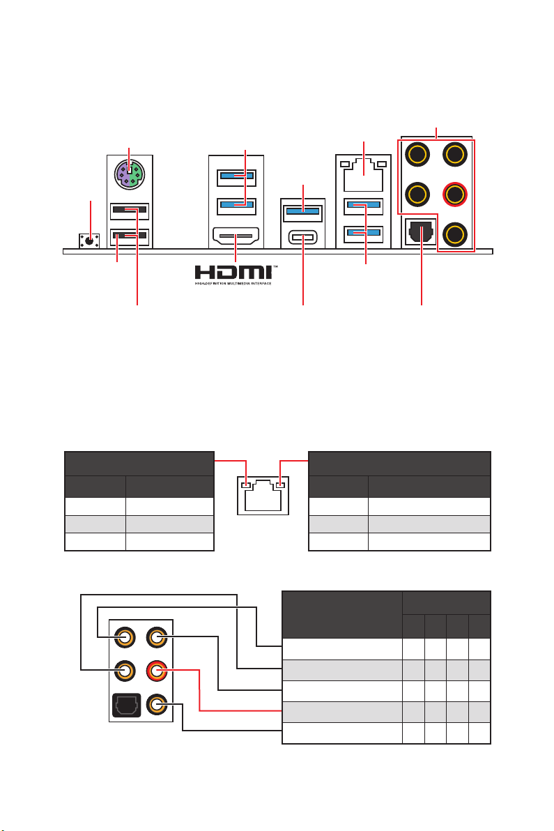
Back Panel
Connectors
I/O Controller
y 1x Flash BIOS Button
y 1x PS/2 keyboard/ mouse combo port
y 2x USB 2.0 ports
y 4x USB 3.2 Gen 1 ports
y 1x HDMI port
y 1x USB 3.2 Gen 2/ 1 Type A port
y 1x USB 3.2 Gen 2/1 Type C port
y 1x LAN(RJ45) port
y 5x OFC audio jacks
y 1x Optical S/PDIF Out connector
NUVOTON NCT6797 Controller Chip
Continued on next page
Specifications
17
Hardware Monitor
Continued from previous page
y CPU/ System/ Chipset temperature detection
y CPU/ System/ Chipset fan speed detection
y CPU/ System/ Chipset fan speed control
Form Factor
BIOS Features
Software
Dragon Center
Features
y ATX Form Factor
y 12 in. x 9.6 in. (30.4 cm x 24.3 cm)
y 1x 256 Mb flash
y UEFI AMI BIOS
y ACPI 6.2, SM BIOS 3.2
y Multi-language
y Drivers
y DRAGON CENTER
y CPU-Z MSI GAMING
y MSI App Player (BlueStacks)
y Google Chrome™ ,Google Toolbar, Google Drive
y Norton™ Internet Security Solution
y DRAGON OPTIMIZATION
y OC Performance
y Hardware Monitor
y True Color
y Mystic Light
y Live Update
Please refer to http://download.msi.
com/manual/mb/DRAGONCENTER2.
pdf for more details.
Continued on next page
18
Specifications

Special Features
Continued from previous page
y Audio
Audio Boost 4
y Storage
Lightning Gen 4 M.2
Turbo M.2
y Fan
Pump Fan
GAMING Fan Control
y LED
Mystic Light 3
Mystic Light Extension (RGB)
Mystic Light Extension (RAINBOW)
Mystic Light Sync
EZ DEBUG LED
y Protection
PCIe Steel Armor
y Performance
Multi GPU-CrossFire Technology
DDR4 Boost
Core Boost
GAME Boost
USB with type A+C
AMD Turbo USB 3.2 Gen 2
y BIOS
Click BIOS 5
Flash BIOS
Specifications
19
Package contents
Please check the contents of your motherboard package. It should contain:
Motherboard X570-A PRO
Cable SATA 6Gb/s Cables 2
8.5H M.2 screws 2
Accessories
Application DVD Driver DVD 1
Documentation Quick Installation Guide 1
Important
If any of the above items are damaged or missing, please contact your retailer.
Case Badge 1
Product Registration Card 1
Package contents
20
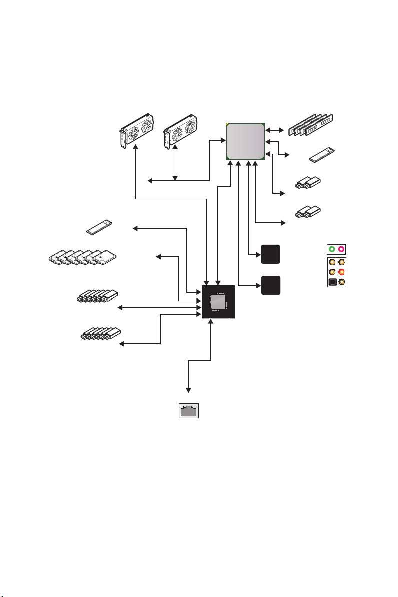
Block Diagram
2 Channel DDR4 Memory
Processor
1x M.2
6x USB 2.0
6x USB 3.2 Gen1
1x M.2
6x SATA 6Gb/s
PCI Express Bus
1x Realtek 8111H LAN
PCH
PCIE
Realtek
ALC1220
NUVOTON
6797
2x USB 3.2 Gen1
2x USB 3.2 Gen2
Front Audio Jacks
Rear Audio Jacks
Block Diagram
21
Rear I/O Panel
PS/2
USB 3.2
Gen1
Type-A
LAN
Audio Ports
USB 3.2
Gen 2
Type-A*
Flash BIOS
Button
Flash BIOS
Port
USB 3.2
Gen 1
Type-A
USB 2.0 Type-A
USB 3.2 Gen 2
Optical S/PDIF-Out
Type-C*
*USB 3.2 Gen2 (3rd Gen AMD Ryzen™) or USB 3.2 Gen1 (2nd Gen AMD Ryzen™/Ryzen™
with Radeon™ Vega Graphics and 2nd Gen AMD Ryzen™ with Radeon™Graphics)
y Flash BIOS Port/ Button — Please refer to page 43 for Updating BIOS with Flash BIOS
Button.
LAN Port LED Status Table
Link/ Activity LED
Status Description
Off No link
Yellow Linked
Blinking Data activity
Speed LED
Status Description
Off 10 Mbps connection
Green 100 Mbps connection
Orange 1 Gbps connection
Audio Ports Configuration
Rear I/O Panel
22
Audio Ports
Channel
2 4 6 8
Center/ Subwoofer Out ● ●
Rear Speaker Out ● ● ●
Line-In/ Side Speaker Out ●
Line-Out/ Front Speaker Out ● ● ● ●
Mic In
(●: connected, Blank: empty)
Loading…
Инструкция
Посмотреть инструкция для MSI X570-A Pro бесплатно. Руководство относится к категории материнские платы, 15 человек(а) дали ему среднюю оценку 8.8. Руководство доступно на следующих языках: русский, английский. У вас есть вопрос о MSI X570-A Pro или вам нужна помощь?
Задайте свой вопрос здесь
Ниже вы найдете технические характеристики изделия и руководства по эксплуатации MSI X570-A Pro.
Материнская плата MSI X570-A Pro является продуктом для компьютеров, совместимым с процессорами AMD Ryzen 3 2-го поколения, AMD Ryzen 3 3-го поколения, AMD Ryzen 5 2-го поколения, AMD Ryzen 5 3-го поколения, AMD Ryzen 7 2-го поколения, AMD Ryzen 7 3-го поколения, AMD Ryzen 9 3-го поколения. Она поддерживает один SMP процессор и имеет разъем Socket AM4.
Материнская плата оснащена чипсетом AMD X570 и имеет 4 слота для памяти типа DIMM, поддерживающих технологию ECC. Количество монтажных отверстий равно 9. Плата также имеет встроенный звуковой чип Realtek ALC1220, поддерживающий 7.1 канала аудиовывода.
MSI X570-A Pro оснащена функцией мониторинга состояния ПК, включая контроль за температурой, вентилятором и ЦП. Эта материнская плата поддерживает операционные системы Windows 10 Education x64, Windows 10 Enterprise x64, Windows 10 Home x64, Windows 10 Pro x64, Windows 10 x64.
Изготовлена материнская плата MSI X570-A Pro из высококачественных материалов для обеспечения надежности и долговечности в эксплуатации.
Производитель процессора
AMD
Чипсет материнской платы
AMD X570
Поддерживаемые типы памяти
DDR4-SDRAM
Слоты PCI Express x1 (поколение 3.x)
3
Поддерживаемые интерфейсы носителя
SATA III
Объём памяти графического адаптера
2048 MB
Главная
| Бренд | MSI |
| Модель | X570-A Pro | X570-A PRO |
| Изделие | материнская плата |
| EAN | 4719072652524, 0824142189627 |
| Язык | русский, английский |
| Тип файла | Руководство пользователя (PDF) |
Процессор
| Производитель процессора | AMD |
| Сокет процессора | Разъем AM4 |
| Совместимые серии процессоров | AMD Ryzen 3 2nd Gen, AMD Ryzen 3 3rd Gen, AMD Ryzen 5 2nd Gen, AMD Ryzen 5 3rd Gen, AMD Ryzen 7 2nd Gen, AMD Ryzen 7 3rd Gen, AMD Ryzen 9 3rd Gen |
| Максимальное число процессоров для SMP | 1 |
Свойства
| Чипсет материнской платы | AMD X570 |
| Аудио чип | Realtek ALC1220 |
| Выходные звуковые каналы | 7.1 канала |
| Мониторинг состояния ПК | CPU, FAN, Temperature |
| Количество отверстий для монтажа | 9 |
| Поддерживаемые операционные системы Windows | Windows 10 Education x64, Windows 10 Enterprise x64, Windows 10 Home x64, Windows 10 Pro x64, Windows 10 x64 |
| Комплектующие для | ПК |
| Формат материнской платы | ATX |
| Семейство чипсета материнской платы | AMD |
Память
| Поддерживаемые типы памяти | DDR4-SDRAM |
| Количество слотов памяти | 4 |
| Тип слотов памяти | DIMM |
| Каналы памяти | Dual-channel |
| Поддерживаемые частоты памяти | 1866,2133,2400,2667,2800,2933,3000,3066,3200,3466,3600,3733,3866,4000,4133,4266,4400 MHz |
| Максимальная внутренняя память | 128 GB |
| Небуферизованная память | Да |
Слоты расширения
| Слоты PCI Express x1 (поколение 3.x) | 3 |
| PCI Express x16 слоты | 2 |
| Количество M.2 (M) слотов | 2 |
Контроллеры хранения данных
| Поддерживаемые интерфейсы носителя | SATA III |
| Уровни RAID | 0, 1,10 |
Графический адаптер
| Объём памяти графического адаптера | 2048 MB |
| Поддержка технологии параллельной обработки | 2-Way CrossFireX |
| Максимальное разрешение | 4096 x 2160 пикселей |
Внутренние порты
| Разъемы USB 2.0 | 2 |
| Разъемы USB 3.2 Gen 1 (3.1 Gen 1) | 2 |
| Разъемы USB 3.2 Gen 2 (3.1 Gen 2) | 0 |
| Количество разъемов SATA III | 6 |
| Количество разъемов SATA II | 0 |
| Количество параллельных разъемов ATA (PATA) | 0 |
| Аудиоразъем передней панели | Да |
| Разъем передней панели | Да |
| Разъем питания ATX (24-конт.) | Да |
| Разъем вентилятора центрального процессора | Да |
| Количество разъемов вентилятора корпуса | 4 |
| Разъем Chassis intrusion | Да |
| TPM коннектор | Да |
| 12В разъем питания | Да |
| RGB LED контактный разъем | Да |
| Коннекторы последовательного порта | 1 |
BIOS
| Тип BIOS | UEFI AMI |
| Размер памяти BIOS | 256 Mbit |
| Версия ACPI | 6.2 |
| Перемычка Clear CMOS | Да |
| Версия BIOS (SMBIOS) | 3.2 |
Порты на задней панели
| Количество портов USB 2.0 | 2 |
| Количество портов USB 3.2 Gen 1 (3.1 Gen 1) Type-A | 4 |
| Количество портов USB 3.2 Gen 1 (3.1 Gen 1) Type-С | 0 |
| Количество портов USB 3.2 Gen 2 (3.1 Gen 2) Type-A | 1 |
| Количество портов USB 3.2 Gen 2 (3.1 Gen 2) Type-С | 1 |
| Количество портов Ethernet LAN ( RJ-45) | 1 |
| Количество портов eSATA | 0 |
| Количество портов PS/2 | 1 |
| Порты FireWire | 0 |
| Количество портов VGA (D-Sub) | 0 |
| Количество HDMI портов | 1 |
| Версия HDMI | 1.4 |
| Количество портов DVI-D | 0 |
| Порт выхода S/PDIF | Да |
| Цифровой оптический аудио выход | 1 |
Сеть
| Подключение Ethernet | Да |
| Тип Ethernet интерфейса | Гигабитный Ethernet |
| Контроллер LAN | Realtek RTL8111H |
| Wi-Fi | Нет |
Вес и размеры
| Ширина | 304 mm |
| Глубина | 243 mm |
| Высота | 268 mm |
Содержимое упаковки
| Поставляемые кабели | SATA |
| Драйвера в комплекте | Да |
Прочие свойства
| Краткое руководство по установке | Да |
| Вес | 1000 g |
Логистические данные
| Код гармонизированной системы описания (HS) | 84733020 |
показать больше
Часто задаваемые вопросы
Не можете найти ответ на свой вопрос в руководстве? Вы можете найти ответ на свой вопрос ниже, в разделе часто задаваемых вопросов о MSI X570-A Pro.
Как установить материнскую плату MSI X570-A Pro в корпус компьютера?
Выравнивайте материнскую плату MSI X570-A Pro с стойками в корпусе, убедитесь, что она подходит должным образом. Затем зафиксируйте ее на месте, используя предоставленные винты.
Как я могу подключить кабели питания к материнской плате {MSI X570-A Pro}?
Найдите основное разъем питания на материнской плате (обычно 24-контактный разъем) и плотно соедините его с соответствующим кабелем от источника питания. Кроме того, если ваш источник питания имеет выделенный разъем питания для процессора (обычно 4 или 8 контактов), соедините его с соответствующим разъемом на материнской плате.
Что мне делать, если моя система не загружается или ничего не отображается на экране?
Убедитесь, что все соединения питания надежно закреплены и правильно установлены. Гарантируйте, что модули оперативной памяти плотно вставлены в соответствующие слоты, и убедитесь в правильном подключении всех необходимых соединений, таких как кабели питания ГП и кабели монитора. Также, попробуйте сбросить CMOS, удалив батарейку CMOS на несколько минут, а затем вновь вставив ее.
Как я могу обновить BIOS на материнской плате MSI X570-A Pro?
Сперва убедитесь, что у вас есть стабильный источник питания. Затем загрузите последнее обновление BIOS с веб-сайта MSI на флеш-накопитель USB. Перезагрузите компьютер и войдите в BIOS, нажав назначенную клавишу (обычно Delete или F2) во время загрузки. Затем перейдите к утилите для обновления BIOS и выберите файл обновления BIOS с флеш-накопителя USB для запуска процесса обновления.
Могу ли я разогнать компоненты при помощи материнской платы MSI X570-A Pro?
Да, материнская плата MSI X570-A Pro поддерживает разгон процессора. Однако, имейте в виду, что неправильное выполнение разгона может нанести вред вашим компонентам. Убедитесь, что у вас достаточное охлаждение и обратитесь к надежным руководствам или консультируйтесь с экспертами для безопасной практики разгона.
Совместима ли материнская плата MSI X570-A Pro с процессорами AMD Ryzen?
Да, MSI X570-A Pro совместима с процессорами AMD Ryzen. Это означает, что пользователи могут легко установить выбранные ими процессоры AMD Ryzen на эту материнскую плату без каких-либо проблем совместимости.
Поддерживает ли MSI X570-A Pro 7.1-канальный аудиовыход?
Да, материнская плата MSI X570-A Pro поддерживает звуковой вывод 7.1 канала. Это означает, что пользователи могут наслаждаться качественным объемным звуком с помощью этой материнской платы, что делает ее идеальным решением для игр или мультимедийных целей.
У MSI X570-A Pro есть функции мониторинга состояния ПК?
Да, у MSI X570-A Pro есть функции мониторинга состояния ПК. Это означает, что пользователи могут следить за важными параметрами, такими как использование ЦП, скорости вентиляторов и температура, позволяя им обеспечить оптимальную производительность и предотвратить перегрев.
Сколько слотов для памяти имеет материнская плата MSI X570-A Pro?
MSI X570-A Pro имеет 4 слота памяти. Это означает, что пользователи могут расширить объем оперативной памяти системы, установив до 4 модулей ОЗУ, что позволяет осуществлять более эффективную многозадачность и обеспечить плавную работу в целом.
Поддерживает ли MSI X570-A Pro память ECC?
Да, MSI X570-A Pro поддерживает ECC-память. Это означает, что пользователи могут использовать модули памяти с методом исправления ошибок (ECC), которые обнаруживают и исправляют ошибки данных, обеспечивая более высокую стабильность и надежность системы, особенно в критических приложениях, таких как серверы или рабочие станции.
Какой вес MSI X570-A Pro?
MSI X570-A Pro имеет вес 1000 g.
Какая высота MSI X570-A Pro?
MSI X570-A Pro имеет высоту 268 mm.
Какая ширина MSI X570-A Pro?
MSI X570-A Pro имеет ширину 304 mm.
Какая толщина MSI X570-A Pro?
MSI X570-A Pro имеет толщину 243 mm.
Инструкция MSI X570-A Pro доступно в русский?
Да, руководствоMSI X570-A Pro доступно врусский .
Не нашли свой вопрос? Задайте свой вопрос здесь
SATA1~6: Разъемы SATA 6Гб/с
Эти разъемы представляют собой интерфейсные порты SATA 6Гб/с. К каждому
порту можно подключить одно устройство SATA.
⚠
Внимание!
∙
Избегайте перегибов кабеля SATA под прямым углом. В противном случае,
возможна потеря данных при передаче.
Кабели SATA оснащены одинаковыми коннекторами с обеих сторон. Однако,
∙
для экономии занимаемого пространства к материнской плате рекомендуется
подключать плоский разъем.
JFP1, JFP2: Разъемы передней панели
Эти разъемы служат для подключения кнопок и светодиодных индикаторов,
расположенных на передней панели.
1
JFP2
JFP1
1
3
5
7
9
Buzzer
1
Speaker
3
SATA2
SATA1
Power LED
Power Switch
2
1
HDD LED
Reset Switch
HDD LED +
2
HDD LED —
4
Reset Switch
6
Reset Switch
8
Reserved
10
Speaker —
2
Buzzer —
4
Компоненты материнской платы
SATA6
SATA5
SATA4
SATA3
10
9
Reserved
Power LED +
Power LED —
Power Switch
Power Switch
No Pin
Buzzer +
Speaker +
17

I
Quick Start
Quick Start
Thank you for purchasing the MSI
®
X570-A PRO motherboard. This
Quick Start section provides demonstration diagrams about how to
install your computer. Some of the installations also provide video
demonstrations. Please link to the URL to watch it with the web
browser on your phone or tablet. You may have even link to the URL
by scanning the QR code.
Kurzanleitung
Danke, dass Sie das MSI
®
X570-A PRO Motherboard gewählt
haben. Dieser Abschnitt der Kurzanleitung bietet eine Demo zur
Installation Ihres Computers. Manche Installationen bieten auch
die Videodemonstrationen. Klicken Sie auf die URL, um diese
Videoanleitung mit Ihrem Browser auf Ihrem Handy oder Table
anzusehen. Oder scannen Sie auch den QR Code mit Ihrem Handy,
um die URL zu öffnen.
Présentation rapide
Merci d’avoir choisi la carte mère MSI
®
X570-A PRO. Ce manuel
fournit une rapide présentation avec des illustrations explicatives
qui vous aideront à assembler votre ordinateur. Des tutoriels vidéo
sont disponibles pour certaines étapes. Cliquez sur le lien fourni
pour regarder la vidéo sur votre téléphone ou votre tablette. Vous
pouvez également accéder au lien en scannant le QR code qui lui est
associé.
Быстрый старт
Благодарим вас за покупку материнской платы MSI
®
X570-A PRO.
В этом разделе представлена информация, которая поможет вам
при сборке комьютера. Для некоторых этапов сборки имеются
видеоинструкции. Для просмотра видео, необходимо открыть
соответствующую ссылку в веб-браузере на вашем телефоне или
планшете. Вы также можете выполнить переход по ссылке, путем
сканирования QR-кода.
III
Quick Start
1
2
3
Important
If you are installing the screw-type CPU heatsink, please follow the figure below to
remove the retention module first and then install the heatsink.
Wenn Sie einen CPU-Kühler mit Schraubenbefestigung einsetzen, folgen Sie bitte
den Anweisungen unten um das Retention-Modul zu entfernen und den Kühler zu
installieren.
Si vous voulez installer un ventirad pour processeur à vis, veuillez suivre les
instructions ci-dessous pour d’abord retirer le module de rétention puis installer le
ventirad.
V
Quick Start
Youtube
HDD LED
RESET SW
JFP1
HDD LED
HDD LED —
HDD LED +
POWER LED —
POWER LED +
POWER LED
1
2 10
9
+
+
+—
——
—
+
Power LED
HDD LED Reset Switch
Reserved
Power Switch
JFP1
1 HDD LED + 2 Power LED +
3 HDD LED — 4 Power LED —
5 Reset Switch 6 Power Switch
7 Reset Switch 8 Power Switch
9 Reserved 10 No Pin
RESET SW
POWER SW
POWER LED+
POWER LED-
HDD LED
Connecting the Front Panel Header/ Anschließen der
Frontpanel—Stiftleiste/ Connecter un connecteur du panneau
avant/ Подключение разъемов передней панели
8
Package contents
Package contents
Please check the contents of your motherboard package. It should contain:
Motherboard X570-A PRO
Cable SATA 6Gb/s Cables 2
Accessories
8.5H M.2 screws 2
Case Badge 1
Product Registration Card 1
Application DVD Driver DVD 1
Documentation Quick Installation Guide 1
⚠
Important
If any of the above items are damaged or missing, please contact your retailer.
15
Overview of Components
PCI_E1~5: PCIe Expansion Slots
⚠
Important
∙
If you install a large and heavy graphics card, you need to use a tool such as MSI
Gaming Series Graphics Card Bolster to support its weight to prevent deformation of
the slot.
∙
For a single PCIe x16 expansion card installation with optimum performance, using
the PCI_E1 slot is recommended.
∙
When adding or removing expansion cards, always turn off the power supply and
unplug the power supply power cable from the power outlet. Read the expansion
card’s documentation to check for any necessary additional hardware or software
changes.
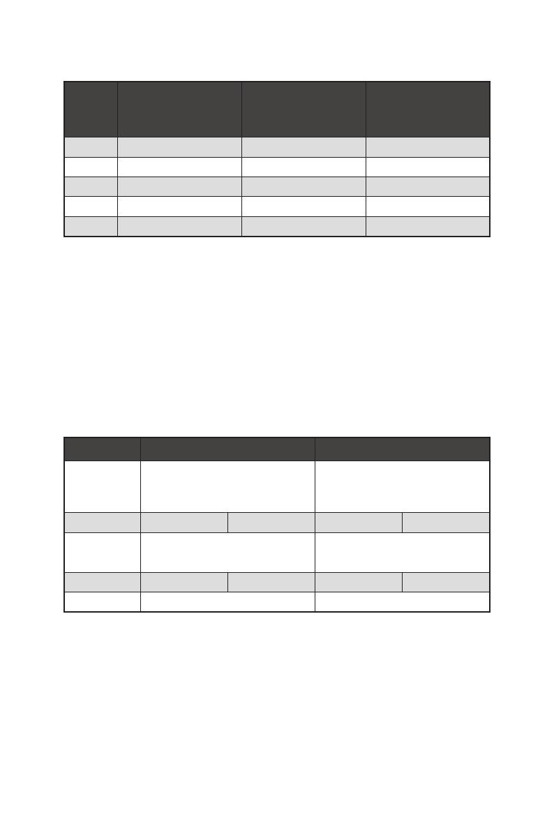
PCIe bandwidth table
Slot Single 2-Way
PCI_E1 (CPU)
@4.0 x16*
or @3.0 x16**
or @3.0 x8***
@4.0 x16*
or @3.0 x16**
or @3.0 x8***
PCI_E2 (PCH) 3.0 x1 — 3.0 x1 —
PCI_E3 (PCH)
4.0 x4*
or 3.0 x4**
/
***
@4.0 x4*
or @3.0 x4**
/
***
PCI_E4 (PCH) — 3.0 x1 — 3.0 x1
PCI_E5 (PCH) 3.0 x1 3.0 x1
Ryzen™, ***: for Ryzen™ with Radeon™ Vega Graphics and 2nd Gen AMD Ryzen™ with
Radeon™ Graphics)
Slots 3rd Gen AMD Ryzen™ 2nd Gen AMD Ryzen™
Ryzen™ with Radeon™
Vega Graphics and 2nd
Gen AMD Ryzen™ with
Radeon™ Graphics
PCI_E1 PCIe 4.0 x16 PCIe 3.0 x16 PCIe 3.0 x8
PCI_E2 PCIe 3.0 x1 PCIe 3.0 x1 PCIe 3.0 x1
PCI_E3 PCIe 4.0 x4 PCIe 3.0 x4 PCIe 3.0 x4
PCI_E4 PCIe 3.0 x1 PCIe 3.0 x1 PCIe 3.0 x1
PCI_E5 PCIe 3.0 x1 PCIe 3.0 x1 PCIe 3.0 x1
17
Overview of Components
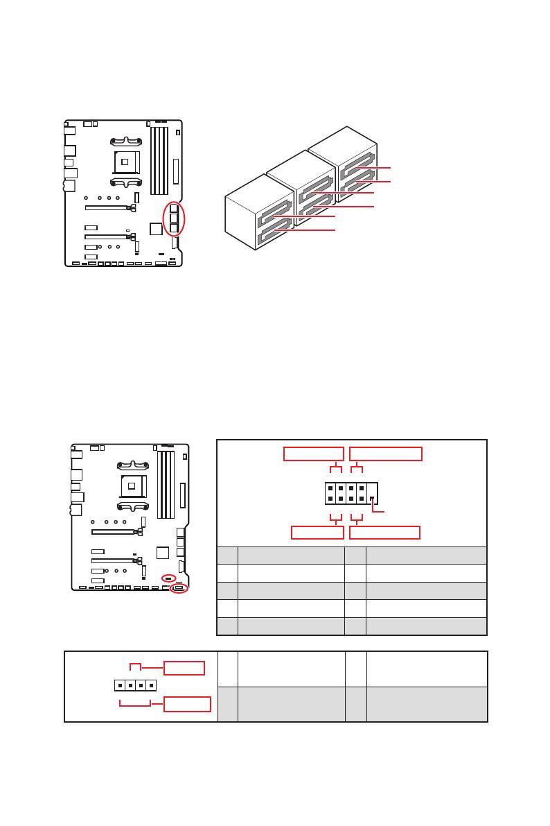
JFP1, JFP2: Front Panel Connectors
These connectors connect to the switches and LEDs on the front panel.
1
2 10
9
+
+
+—
——
—
+
Power LED
HDD LED Reset Switch
Reserved
Power Switch
JFP1
1 HDD LED + 2 Power LED +
3 HDD LED — 4 Power LED —
5 Reset Switch 6 Power Switch
7 Reset Switch 8 Power Switch
9 Reserved 10 No Pin
1
JFP2
+
+
—
—
Speaker
Buzzer
1 Speaker — 2 Buzzer +
3 Buzzer — 4 Speaker +
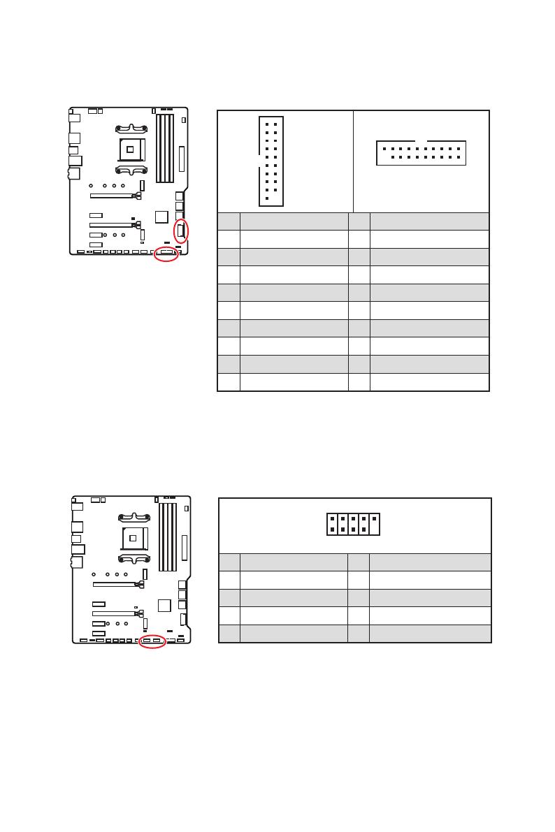
SATA1~6: SATA 6Gb/s Connectors
These connectors are SATA 6Gb/s interface ports. Each connector can connect to one
SATA device.
⚠
Important
∙
Please do not fold the SATA cable at a 90-degree angle. Data loss may result during
transmission otherwise.
∙
SATA cables have identical plugs on either sides of the cable. However, it is
recommended that the flat connector be connected to the motherboard for space
saving purposes.
SATA5
SATA3
SATA6
SATA4
SATA1
SATA2
20
Overview of Components
JUSB3~4: USB 3.2 Gen1 Connectors
These connectors allow you to connect USB 3.2 Gen1 ports on the front panel.
⚠
Important
Note that the Power and Ground pins must be connected correctly to avoid possible
damage.
1
10 11
20
JUSB4
1 10
1120
JUSB3
1 Power 11 USB2.0+
2 USB3_RX_DN 12 USB2.0-
3 USB3_RX_DP 13 Ground
4 Ground 14 USB3_TX_C_DP
5 USB3_TX_C_DN 15 USB3_TX_C_DN
6 USB3_TX_C_DP 16 Ground
7 Ground 17 USB3_RX_DP
8 USB2.0- 18 USB3_RX_DN
9 USB2.0+ 19 Power
10 NC 20 No Pin
JUSB1~2: USB 2.0 Connectors
These connectors allow you to connect USB 2.0 ports on the front panel.
1
2 10
9
1 VCC 2 VCC
3 USB0- 4 USB1-
5 USB0+ 6 USB1+
7 Ground 8 Ground
9 No Pin 10 NC
⚠
Important
∙
Note that the VCC and Ground pins must be connected correctly to avoid possible
damage.
∙
In order to recharge your iPad,iPhone and iPod through USB ports, please install
MSI
®
DRAGON CENTER utility.
15
Übersicht der Komponenten
PCI_E1~5: PCIe Erweiterungssteckplätze
⚠
Wichtig
∙
Wenn Sie eine große und schwere Grafikkarte einbauen, benötigen Sie einen
Grafikkarten-Stabilisator (Graphics Card Bolster) der das Gewicht trägt und eine
Verformung des Steckplatzes vermeidet.
∙
Für die Installation einer einzelnen PCIe x16 Erweiterungskarte mit optimaler
Leistung, empfehlen wir den PCI_E1 Steckplatz zu verwenden.
∙
Achten Sie darauf, dass Sie den Strom abschalten und das Netzkabel aus der
Steckdose herausziehen, bevor Sie eine Erweiterungskarte installieren oder
entfernen. Lesen Sie bitte auch die Dokumentation der Erweiterungskarte, um
notwendige zusätzliche Hardware oder Software-Änderungen zu überprüfen.
Tabelle der PCIe Bandbreiten
Steckplatz Einzel 2-Wege
PCI_E1 (CPU)
@4.0 x16*
or @3.0 x16**
or @3.0 x8***
@4.0 x16*
or @3.0 x16**
or @3.0 x8***
PCI_E2 (PCH) 3.0 x1 — 3.0 x1 —
PCI_E3 (PCH)
4.0 x4*
or 3.0 x4**
/
***
@4.0 x4*
or @3.0 x4**
/
***
PCI_E4 (PCH) — 3.0 x1 — 3.0 x1
PCI_E5 (PCH) 3.0 x1 3.0 x1
™
der 3. Generation
Prozessoren, **: Für AMD Ryzen
™
der 2. Generation Prozessoren, ***: Für Ryzen
™
Prozessoren mit Radeon
™
Vega Grafikprozessor und AMD Ryzen
™
der 2. Generation
Prozessoren mit Radeon
™
Grafikprozessor)
Steckplätze
AMD Ryzen
™
der
3. Generation
Prozessoren
AMD Ryzen
™
der
2. Generation
Prozessoren
Ryzen
™
Prozessoren
mit Radeon
™
Vega
Grafikprozessor und AMD
Ryzen
™
der 2. Generation
Prozessoren mit Radeon
™
Grafikprozessor
PCI_E1 PCIe 4.0 x16 PCIe 3.0 x16 PCIe 3.0 x8
PCI_E2 PCIe 3.0 x1 PCIe 3.0 x1 PCIe 3.0 x1
PCI_E3 PCIe 4.0 x4 PCIe 3.0 x4 PCIe 3.0 x4
PCI_E4 PCIe 3.0 x1 PCIe 3.0 x1 PCIe 3.0 x1
PCI_E5 PCIe 3.0 x1 PCIe 3.0 x1 PCIe 3.0 x1

17
Übersicht der Komponenten
JFP1, JFP2: Frontpanel-Anschlüsse
Diese Anschlüsse verbinden die Schalter und LEDs des Frontpanels.
1
2 10
9
+
+
+—
——
—
+
Power LED
HDD LED Reset Switch
Reserved
Power Switch
JFP1
1 HDD LED + 2 Power LED +
3 HDD LED — 4 Power LED —
5 Reset Switch 6 Power Switch
7 Reset Switch 8 Power Switch
9 Reserved 10 No Pin
1
JFP2
+
+
—
—
Speaker
Buzzer
1 Speaker — 2 Buzzer +
3 Buzzer — 4 Speaker +
SATA1~6: SATA 6Gb/s Anschlüsse
Dieser Anschluss basiert auf der Hochgeschwindigkeitsschnittstelle SATA 6 Gb/s. Pro
Anschluss kann ein SATA Gerät angeschlossen werden.
⚠
Wichtig
∙
Knicken Sie das SATA-Kabel nicht in einem 90° Winkel. Datenverlust könnte die
Folge sein.
∙
SATA-Kabel haben identische Stecker an beiden Enden. Es wird empfohlen den
flachen Stecker auf dem Motherboard einstecken.
SATA5
SATA3
SATA6
SATA4
SATA1
SATA2
18
Übersicht der Komponenten
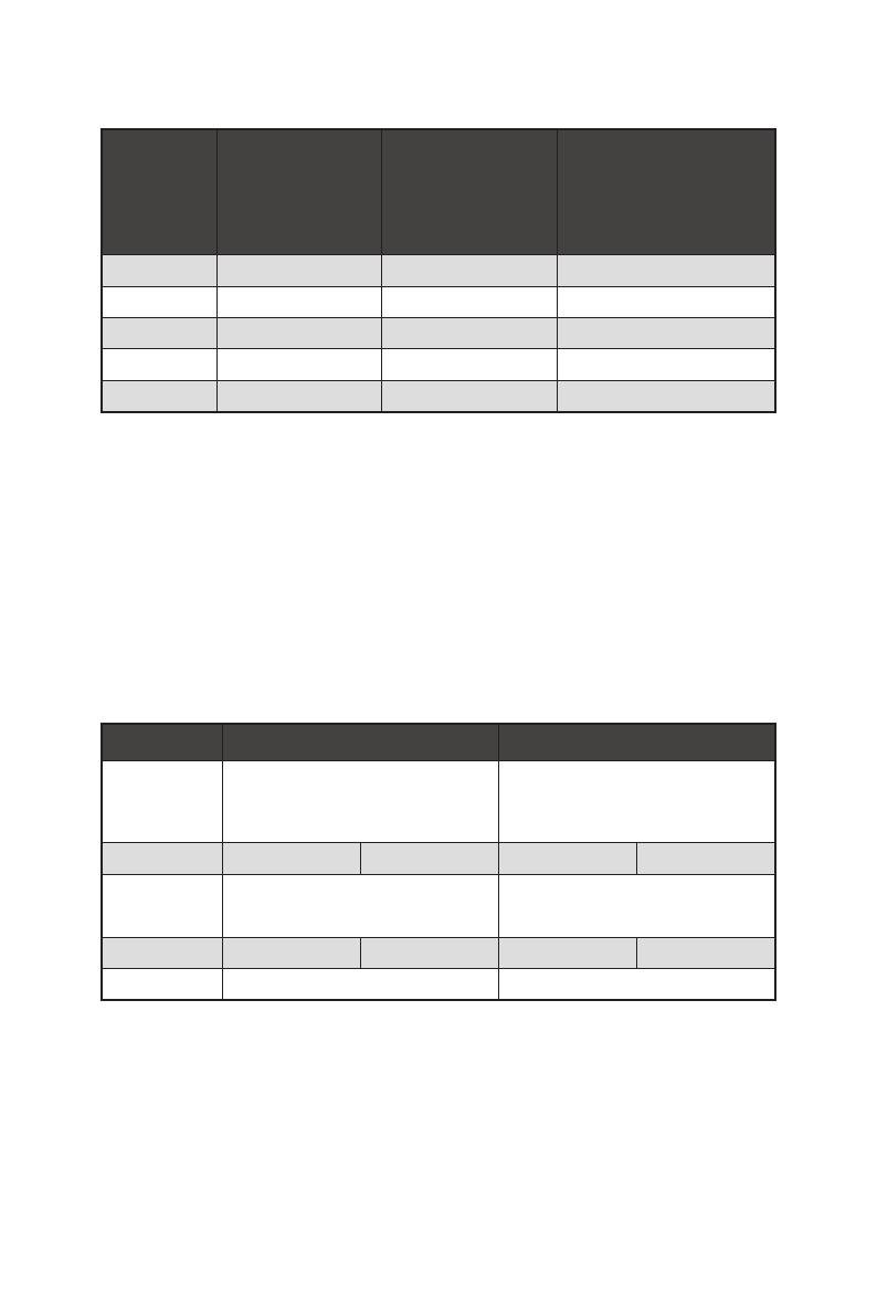
24
131
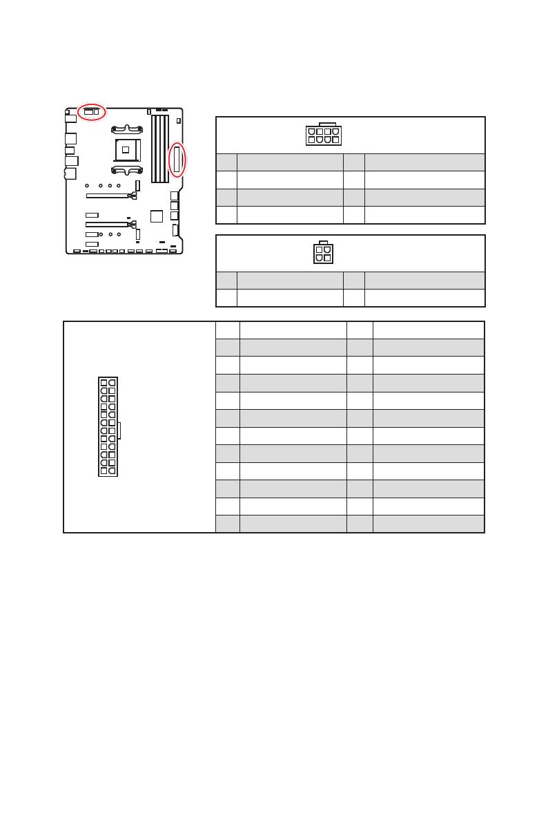
12
ATX_PWR1
1 +3.3V 13 +3.3V
2 +3.3V 14 -12V
3 Ground 15 Ground
4 +5V 16 PS-ON#
5 Ground 17 Ground
6 +5V 18 Ground
7 Ground 19 Ground
8 PWR OK 20 Res
9 5VSB 21 +5V
10 +12V 22 +5V
11 +12V 23 +5V
12 +3.3V 24 Ground
5
4 1
8
CPU_PWR1
1 Ground 5 +12V
2 Ground 6 +12V
3 Ground 7 +12V
4 Ground 8 +12V
⚠
Wichtig
Stellen Sie sicher, dass alle Anschlüsse mit den richtigen Anschlüssen des Netzteils
verbunden sind, um einen stabilen Betrieb der Hauptplatine sicherzustellen.
CPU_PWR1~2, ATX_PWR1: Stromanschlüsse
Mit diesen Anschlüssen verbinden Sie die ATX Stromstecker.
3
2 1
4
CPU_PWR2
1 Ground 3 +12V
2 Ground 4 +12V