

昆山科瑞艾特电气有限公司
Add:江苏省昆山市古城路西侧新城翡翠湾 47 幢 505 室
PC: 215300
Tel:0512-50132715
Fax: 0512-50132716
联系人:周贵
手机:15862659855 13338649855
QQ:353850790 35731075 837638847 31740304
EMAIL:
网址:
昆山科瑞艾特电气有限公司是以自动化专业为主体集贸易、技术、工
程成套为一体的专业型公司。
一、经营品牌
1、欧陆 SSD 直流调速器 512C、514C、590C、590+及配件系列;
2、德国西门子全系列产品包括:
西门子 6RA28 系列直流调速器,西门子 6RA70 系列直流调速器;
zhougui8012@163.com
http://www.kunshan-create.com
S5-系列、S7-200 系列、S7-300 系列、S7-400 系列 CPU、功
能模块 FM、扩展模块 SM、接口模块 IM、通讯模块 CP 及相应附件、
配件、软件;
西门子工控机、人机界面 TD、OP、TP、MP、LOGO!、PS 电源、SITOP
电源、PROFIBUS 网络产品;

西门子各系列编程组态软件 STEP7-Micro/WIN、STEP7、WINcc、
PROTool;
西门子通用型变频器 MM420、MM430、MM440、6SE70 高性能变频
器、工程变频器
3、富 士:变频器、可编程控制器、伺服、数控系统、触摸屏 .
4、ABB:变频器、直流调速器.
5、AB(罗克韦尔)可编程控制器,变频器.
二、提供 SSD590 系列直流调速器维修服务,主要维修主板及电源板。
三、电控系统(电控成套及设备电控改造):
1、冶金行业:单(可逆)轧机、连轧机、酸洗线、拉弯矫直机、平
整机等;
2、线缆行业:成缆机、拉伸机、护套机、交联生产线;
3、橡塑行业:单/双螺杆挤出机、压延机、流延机、板/型材生产线
等.
4、机床控制系统的改造:龙门刨床,镗床,铣床等。

650 Series
AC Drive
Frame 1, 2 & 3
Product Manual
HA464828U003 Issue 7
Compatible with Version 4.9 Software onwards
WARRANTY
Parker SSD Drives warrants the goods against defects in design, materials and workmanship for the period of 12
months from the date of delivery on the terms detailed in Parker SSD Drives Standard Conditions of Sale IA058393C.
Parker SSD Drives reserves the right to change the content and product specification without notice.
© Copyright 2007 Parker SSD Drives, a division of Parker Hannifin Ltd.
All rights strictly reserved. No part of this document may be stored in a retrieval system, or transmitted in any
form or by any means to persons not employed by a Parker SSD Drives company without written permission
from Parker SSD Drives, a division of Parker Hannifin Ltd . Although every effort has been taken to ensure the
accuracy of this document it may be necessary, without notice, to make amendments or correct omissions.
Parker SSD Drives cannot accept responsibility for damage, injury, or expenses resulting therefrom.

Requirements
IMPORTANT: Please read this information BEFORE installing the equipment.
Intended Users
This manual is to be made available to all persons who are required to install, configure or
service equipment described herein, or any other associated operation.
The information given is intended to highlight safety issues, EMC considerations, and to enable
the user to obtain maximum benefit from the equipment.
Complete the following table for future reference detailing how the unit is to be installed and
used.
INSTALLATION DETAILS
Serial Number
(see product label)
Where installed
(for your own
information)
Unit used as a:
(refer to Certification
for the Inverter)
Unit fitted:
R Component R Relevant Apparatus
R Wall-mounted R Enclosure
Application Area
The equipment described is intended for industrial motor speed control utilising AC induction or
AC synchronous machines.
Personnel
Installation, operation and maintenance of the equipment should be carried out by qualified
personnel. A qualified person is someone who is technically competent and familiar with all
safety information and established safety practices; with the installation process, operation and
maintenance of this equipment; and with all the hazards involved.
Product Warnings
Caution
Risk of electric
shock
Cont.2
Caution
Refer to
documentation
Earth/Ground
Protective
Conductor
Terminal

Hazards
DANGER! — Ignoring the following may result in injury
1. This equipment can endanger life by exposure to
rotating machinery and high voltages.
2. The equipment must be permanently earthed due to
the high earth leakage current, and the drive motor
must be connected to an appropriate safety earth.
3. Ensure all incoming supplies are isolated before
working on the equipment. Be aware that there may
be more than one supply connection to the drive.
5. For measurements use only a meter to IEC 61010 (CAT
III or higher). Always begin using the highest range.
CAT I and CAT II meters must not be used on this
product.
6. Allow at least 5 minutes for the drive’s capacitors to
discharge to safe voltage levels (<50V). Use the
specified meter capable of measuring up to 1000V dc &
ac rms to confirm that less than 50V is present between
all power terminals and earth.
4. There may still be dangerous voltages present at
power terminals (motor output, supply input phases,
DC bus and the brake, where fitted) when the motor
is at standstill or is stopped.
7. Unless otherwise stated, this product must NOT be
dismantled. In the event of a fault the drive must be
returned. Refer to «Routine Maintenance and Repair».
WARNING! — Ignoring the following may result in injury or damage to equipment
SAFETY
Where there is conflict between EMC and Safety requirements, personnel safety shall always take precedence.
• Never perform high voltage resistance checks on the
wiring without first disconnecting the drive from the
circuit being tested.
• Whilst ensuring ventilation is sufficient, provide
guarding and /or additional safety systems to
prevent injury or damage to equipment.
• When replacing a drive in an application and before
returning to use, it is essential that all user defined
parameters for the product’s operation are correctly
installed.
• All control and signal terminals are SELV, i.e. protected
by double insulation. Ensure all external wiring is rated
for the highest system voltage.
• Thermal sensors contained within the motor must have
at least basic insulation.
• All exposed metalwork in the Inverter is protected by
basic insulation and bonded to a safety earth.
• RCDs are not recommended for use with this product
but, where their use is mandatory, only Type B RCDs
should be used.
EMC
• In a domestic environment this product may cause
radio interference in which case supplementary
mitigation measures may be required.
• This equipment contains electrostatic discharge
(ESD) sensitive parts. Observe static control
precautions when handling, installing and servicing
this product.
CAUTION!
• This is a product of the restricted sales distribution class
according to IEC 61800-3. It is designated as
“professional equipment” as defined in EN61000-3-2.
Permission of the supply authority shall be obtained
before connection to the low voltage supply.
APPLICATION RISK
• The specifications, processes and circuitry described herein are for guidance only and may need to be adapted to the
user’s specific application. We can not guarantee the suitability of the equipment described in this Manual for
individual applications.
RISK ASSESSMENT
Under fault conditions, power loss or unintended operating conditions, the drive may not operate as intended.
In particular:
• Stored energy might not discharge to safe levels
as quickly as suggested, and can still be present
even though the drive appears to be switched off
A drive is a component within a drive system that may influence its operation or effects under a fault condition.
Consideration must be given to:
• Stored energy • Supply disconnects • Sequencing logic • Unintended operation
• The motor’s direction of rotation might not be controlled
• The motor speed might not be controlled
• The motor might be energised
Cont.3
650 Quick Start
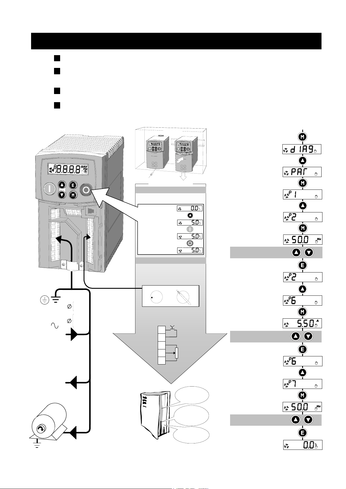
Mount the drive vertically in a lockable cubicle.
Is the drive to operate in Local (using the keypad) or Remote Control?
If Remote Control, make Control Connections.
Make Power Connections. Power-on and follow the Quick Set-Up procedure.
Apply a small setpoint. Start and stop the motor.
Frame 1
Mounting Options
Cubicle
Control Options
LOCAL CONTROL (DEFAULT)
Requires Power Connections only
Control is via the Keypad
Local Setpoint
Press to apply
a small setpoint
Press to start the
motor and it will ramp
to the setpoint
Press to stop the
motor and it will ramp
to zero
REMOTE CONTROL
Requires Power Connections and
Control Connections
Control is via your control panel
See Chapter 5 to select Remote
SPEED
STOP START
Quick Set-Up
Hold the M key until
DIAG is displayed
Navigate to the PAR menu
Press to enter the menu
and see the first parameter
Press to show the next
parameter
Press to edit the
MAX SPEED parameter
Adjust MAX SPEED
Press to exit the parameter
Press (4 times) to show P6
POWER-ON
Power
Supply
Motor
Thermistor
(link the terminals
if temperature
sensors not used)
Power Connections
1
3
L1
N
L1
L2
L3
TH1A
TH1B
M1/U
M2/V
M3/W
Match the motor
voltage to the
drive voltage
Refer to the
motor nameplate
for Star/Delta
voltages
0
100
Control Connections
Single Wire Starting
2-position switch
DIN1
+24V
+10V REF
AIN1
0V
7
6
4
2
1
Start
Speed
Reference
Chapters 3 and 4
install and run
the product
Chapter 5
details the
Keypad and
menu system
Chapter 9
holds many of the
technical details
PLEASE READ THE MANUAL
Press to edit the MOTOR
CURRENT parameter
Adjust MOTOR CURRENT
Refer to motor nameplate
Press to exit the parameter
Press to show P7
Press to edit the BASE
FREQUENCY parameter
Adjust BASE FREQUENCY
Press (3 times) to display
the Local Setpoint
Cont.4

Contents Page
Contents
Chapter 1 GETTING STARTED
Introduction ……………………………………………………………………………………..1-1
Equipment Inspection ………………………………………………………………………………….1-1
Storage and Packaging ……………………………………………………………………………….1-1
About this Manual …………………………………………………………………………….1-1
• Software Product Manual …………………………………………………………….1-1
Chapter 2 AN OVERVIEW OF THE D RIVE
Component Identification ………………………………………………………………….. 2-1
Chapter 3 INSTALLING THE DRIVE
Mechanical Installation …………………………………………………………………….. 3-1
Mounting the Drive……………………………………………………………………………………..3-1
Ventilation ………………………………………………………………………………………………..3-1
Electrical Installation ………………………………………………………………………… 3-2
Wiring Instructions………………………………………………………………………………………3-2
• Local Control Wiring ………………………………………………………………….. 3-2
• Remote Control Wiring……………………………………………………………….. 3-2
Connection Diagram………………………………………………………………………………….. 3-3
• Control Wiring Connections …………………………………………………………3-4
• Power Wiring Connections …………………………………………………………..3-4
• Terminal Block Acceptance Sizes…………………………………………………… 3-5
Optional Equipment ………………………………………………………………………….3-6
• Fitting the Remote 6511 Keypad …………………………………………………… 3-6
• Fitting the Remote 6521/6901/6911 Keypad………………………………….. 3-7
• RS485/RS232 Communication Module …………………………………………..3-8
• Line Choke…………………………………………………………………………….. 3-10
Chapter 4 OPERATING THE DRIVE
Pre-Operation Checks ……………………………………………………………………….4-1
Initial Start-up Routines …………………………………………………………………….4-1
Local Control Operation……………………………………………………………………………… 4-2
Remote Control Operation …………………………………………………………………………..4-2
Chapter 5 THE KEYPAD
Controlling the Drive using the Keypad………………………………………………. 5-1
Control Key Definitions………………………………………………………………………………..5-1
Display Indications ……………………………………………………………………………………..5-2
Drive Status Indications………………………………………………………………………………..5-2
The DIAGNOSTICS Menu ……………………………………………………………………5-2
The Menu System……………………………………………………………………………… 5-3
How To Change a Parameter Value ………………………………………………………………. 5-4
Special Menu Features ………………………………………………………………………5-4
Resetting to Factory Defaults (2-button reset)…………………………………………………….5-4
Changing the Drive Operating Frequency ……………………………………………………….5-4
Selecting Local or Remote Control…………………………………………………………………. 5-4
Password Protection ……………………………………………………………………………………5-5
Quick Application Selection ………………………………………………………………………….5-5
Selecting the Menu Detail ……………………………………………………………………………. 5-5
Chapter 6 PROGRAMMING YOUR A PPLICATION
MMI Parameters ………………………………………………………………………………. 6-1
• Configuring Terminal 10 (Digital Input/Output)………………………………..6-8
• PID — Tuning Your Drive ………………………………………………………………6-8
• Auto Restart……………………………………………………………………………… 6-9
• Skip Frequencies……………………………………………………………………… 6-10
Cont.5

Contents Page
Contents
• Minimum Speed Mode………………………………………………………………6-11
Product-Related Default Values ……………………………………………………………………6-11
• * Frequency Dependent Parameters ……………………………………………..6-11
• ** Power Dependent Parameters…………………………………………………. 6-12
Chapter 7 TRIPS AND FAULT FINDING
Trips ……………………………………………………………………………………………….. 7-1
Trip Warning Message ………………………………………………………………………………..7-1
What Happens when a Trip Occurs………………………………………………………………..7-1
Resetting a Trip Condition…………………………………………………………………………….7-1
Using the Keypad to Manage Trips…………………………………………………………………7-1
Hexadecimal Representation of Trips………………………………………………………………7-4
Fault Finding……………………………………………………………………………………. 7-5
Chapter 8 ROUTINE MAINTENANCE AND R EPAIR
Routine Maintenance………………………………………………………………………… 8-1
Repair ……………………………………………………………………………………………..8-1
Saving Your Application Data ……………………………………………………………………….8-1
Returning the Unit to Parker SSD Drives…………………………………………………………..8-1
Disposal ………………………………………………………………………………………………….. 8-1
Chapter 9 TECHNICAL SPECIFICATIONS
Understanding the Product Code …………………………………………………………………..9-1
• Model Number (Europe)………………………………………………………………9-1
• Catalog Number (North America)………………………………………………….9-2
Environmental Details………………………………………………………………………………….9-3
Power Details…………………………………………………………………………………………….9-3
User Relay ………………………………………………………………………………………………..9-3
Electrical Ratings ……………………………………………………………………………………….. 9-4
Analog Inputs/Outputs ………………………………………………………………………………..9-5
Digital Inputs …………………………………………………………………………………………….9-5
Digital Outputs ………………………………………………………………………………………….9-5
Cabling Requirements for EMC Compliance……………………………………………………. 9-5
Internal Dynamic Braking Circuit……………………………………………………………………9-6
External Brake Resistor ………………………………………………………………………………..9-6
Supply Harmonic Analysis (230V filtered) ……………………………………………………….9-7
Supply Harmonic Analysis (400V filtered) ……………………………………………………….9-8
Supply Harmonic Analysis (230V unfiltered)……………………………………………………. 9-9
Supply Harmonic Analysis (400V unfiltered)…………………………………………………..9-10
Chapter 10 C ERTIFICATION FOR THE DRIVE
Requirements for EMC Compliance ……………………………………………………10-1
Earthing Requirements……………………………………………………………………………….10-1
Requirements for UL Compliance ……………………………………………………… 10-1
European Directives and the CE Mark……………………………………………….. 10-3
CE Marking for Low Voltage Directive …………………………………………………………..10-3
CE Marking for EMC — Who is Responsible? …………………………………………………..10-3
EMC Compliance ……………………………………………………………………………..10-3
Certificates ……………………………………………………………………………………………..10-4
Chapter 11 S ERIAL COMMUNICATIONS
Connection to the P3 Port ………………………………………………………………… 11-1
Chapter 12 A PPLICATIONS
The Default Application ……………………………………………………………………12-1
How to Load an Application ……………………………………………………………..12-1
Application Description ……………………………………………………………………12-1
Cont.6

1GETTING STARTED
Introduction
The 650 Series AC Drive provides simple, compact, and low-cost speed control for 3-phase
induction motors.
It operates as an Open-loop Inverter (V/F Fluxing).
This manual describes the low-power end of the 650 product range for the following motor
power ratings:
Getting Started 1-1
Frame 1 230V 1 0.25 – 0.75kW 0.3 — 1.0 Hp
Frame 2 230V 1 1.1 – 1.5kW 1.5 — 2.0 Hp
Frame 2 400V 3 0.37 – 2.2kW 0.5 — 3.0 Hp
Frame 3 230V 1 2.2kW 3.0 Hp
Frame 3 230V 3 2.2 – 4.0kW 3.0 — 5.0 Hp
Frame 3 400V 3 3.0 – 7.5kW 4.0 — 10.0 Hp
The drive features:
• Local or Remote mode operation
• Support for RS485 and Modbus RTU comms protocols
• SELV control terminals (Safe Extra Low Volts)
• Intelligent monitoring strategy to avoid nuisance tripping
• In-built protection of the unit against overloads, excessive voltages, phase-to-phase and
phase-to-earth short circuits
• An internal RFI filter is fitted as standard
• An internal dynamic brake switch for connection to an external resistor (Frame 3: 230V, and
400V units only)
• Quiet operation
Note: Do not attempt to control motors whose rated current is less than 50% of the drive rated
current. Poor motor control or Autotune problems may occur if you do.
Nominal Input Voltage Phase Drive Power
Equipment Inspection
• Check for signs of transit damage
• Check the drive is suitable for your requirements by reading the Product Code on the rating
label. Refer to Chapter 9: “Technical Specifications” — Understanding the Product Code.
If the unit is damaged, refer to Chapter 8: “Routine Maintenance and Repair” for information on
returning damaged goods.
Storage and Packaging
Save the packaging in case of return. Improper packaging can result in transit damage.
If the unit is not being installed immediately, store the unit in a well-ventilated place away from
high temperatures, humidity, dust or metal particles.
About this Manual
This manual is intended for use by the installer, user and programmer of the drive. It assumes a
reasonable level of understanding in these three disciplines.
Note: Please read all Safety Information before proceeding with the installation and operation
of this unit.
It is important that you pass the manual on to any new user of this unit.
Software Product Manual
An accompanying Software Product Manual is available for download from the Parker SSD
Drives website: www.SSDdrives.com.
650 Series AC Drive
2-1 An Overview of the Drive
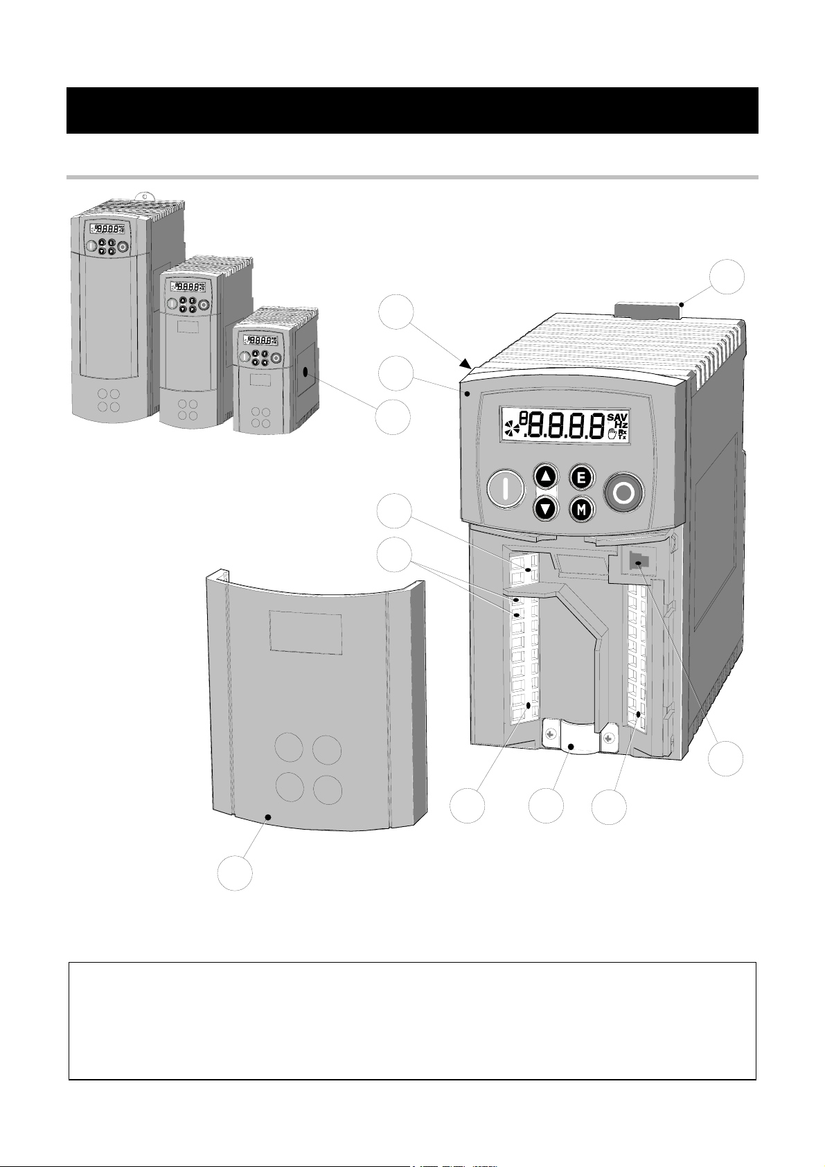
1AN OVERVIEW OF THE DRIVE
Component Identification
1
2
9
Frame 2 Frame 1Frame 3
3
8
10
5
4
Figure 2-1 View of Component Parts (Frame 1 illustrated)
6
11
7
1
Main drive assembly
2
Keypad
3
DIN clip/fixing bracket
4
Terminal cover
5
Power terminals
6
Motor cable screen clamp
7
Control terminals
8
Volt-free relay contacts
9
Product rating label
10
Motor thermistor terminals
11
RS232 port — P3 (optional)
650 Series AC Drive
0INSTALLING THE DRIVE
IMPORTANT: Read Chapter 10: “Certification for the Drive” before installing this unit.
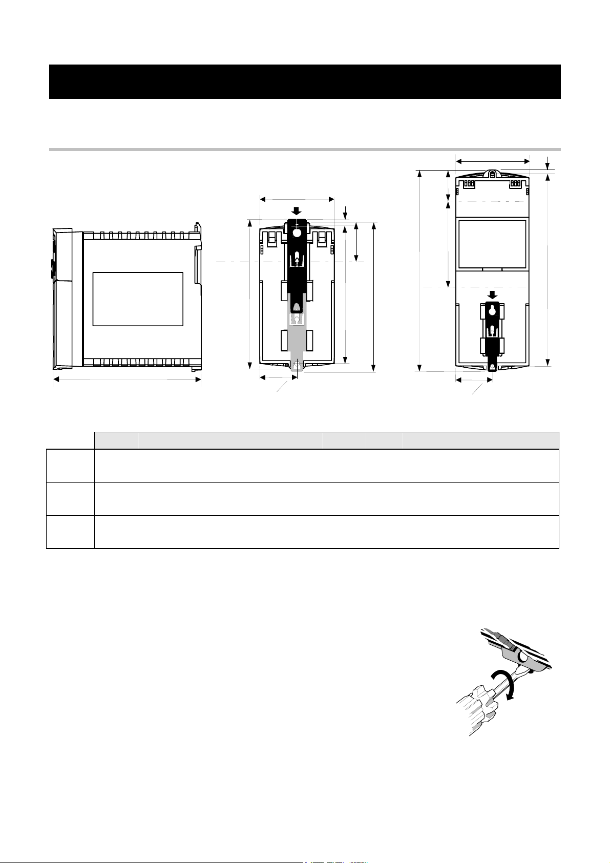
Mechanical Installation
Installing the Drive 3-1
D
SIDE VIEW — Frame 1 illustrated
The DIN clip is repositioned on Frames 1 and 2
to provide the upper fixing hole when wall-mounting
W
C
H1
H3
H4
DIN
centreline
H2
W
2
REAR VIEW — Frame 1 illustrated
(Frame 2 similar)
H2
W
H3
DIN
centreline
H4
DIN centreline
W
2
REAR VIEW — Frame 3
C
H1
Fixing Torque Weight H1 Fixing Centres H2 H3 H4 C W D
Frame 1 M4 1.5Nm 0.85kg 132 143 35 139 6 73 142
(5.2”) (5.6”) (1.4”) (5.5”) (0.2”) (2.9”) (5.6”)
Frame 2 M5 3.0Nm 1.4kg 188 201 35 194 6.5 73 173
(7.4”) (7.9”) (1.4”) (7.7”) (0.24”) (2.9”) (6.8”)
Frame 3 M5 3.0Nm 2.7kg 242 260 38 112 5 96 200
(9.5”) (10.2”) (1.5”) (4.4”) (0.2”) (3.8”) (7.9”)
Dimensions are in millimetres ( inches )
Mounting the Drive
Ventilation
650 Series AC Drive
To maintain compliance with European Electrical Safety Standard VDE0160(1994)/EN50178
(1998) the unit must be mounted inside a control cubicle that requires a tool for opening. The
cubicle should provide 15dB attenuation to radiated emissions between 30-100MHz.
Mount the drive vertically on a solid, flat, non-flammable, vertical
surface. It can be panel-mounted, or rail-mounted on a rail
complying with EN50022 (35mm DIN).
DIN Mounting
To DIN mount the unit, hang the unit on the top DIN rail and push
the unit onto the bottom DIN rail until it snaps in to position. Secure
with a lower screw fixing. To release the unit, use a flat bladed
screwdriver as shown.
Maintain a minimum air clearance for ventilation of 100mm (4 inches) above and below the
unit. When mounting two or more 650 units together, these clearances are additive. Ensure that
the mounting surface is normally cool. Be aware that adjacent equipment may generate heat and
also have clearance requirements. Provided the minimum clearance for ventilation is maintained,
650 drives may be mounted side-by-side.
lower
fixing
hole
3-2 Installing the Drive
Electrical Installation
IMPORTANT: Read the Safety Information on page Cont. 2 before proceeding.
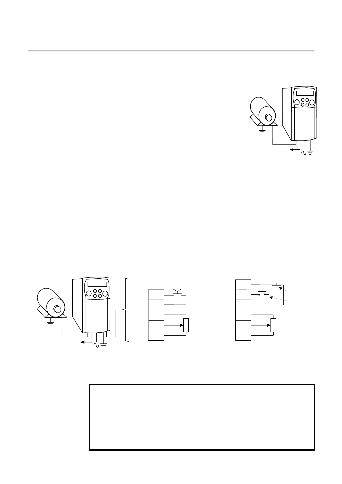
Wiring Instructions
Local Control Wiring
This is the simplest installation. Every new drive will operate in
Local Control when first powered-up. The keypad is used to start
and stop the drive.
Refer to the Connection Diagram and install the:
• Thermistor cable, or link/jumper terminals TH1A and TH1B
if not used (we recommend you use a thermistor)
• Motor cable
• Supply cable
• Follow the earthing/grounding and screening advice
Refer to Chapter 4: «Operating the Drive»- Local Control
Operation.
Minimum Connections
To motor thermistor,
or link terminals
TH1A and TH1B
Remote Control Wiring
If operating in Remote Control you will use your control panel to start and stop the drive, via a
speed potentiometer and switches or push-buttons.
Your wiring of the control terminals will be governed by the Application you use: refer to
Chapter 12 for an explanation of the various Applications you can select and the appropriate
control wiring. Application 1 is the default Application.
The diagram below shows the minimum connections to operate the drive for single-wire
(switch) starting, and push-button starting. Other control connections for your Application,
shown in Chapter 12, and can be made to suit your system.
Referring to the Connection Diagram:
• Follow the instructions for Local Control Wiring, as detailed above
• Install using minimum connections (suitable for Application 1only), or refer to Chapter 12
and install the appropriate control wiring for your system
Minimum Connections for Application 1:
+10V REF
To motor thermistor,
or link terminals
TH1A and TH1B
Note: You can still operate the drive in Local mode, if necessary, with any Application selected.
Refer to Chapter 4: «Operating the Drive» and follow the relevant instructions for Single Wire
Starting or Push-Button Starting.
This product is designated as “professional equipment”
as defined in EN61000-3-2. Where enforced, permission of the supply authority shall
be obtained before connection to the low voltage domestic supply.
Ensure that all wiring is electrically isolated and cannot be made “live”
The drive is suitable for use with both earth referenced supplies (TN) and non-
earth referenced supplies (IT) when fitted with an internal ac supply EMC filter.
Single Wire Starting
DIN1
+24V
7
6
4
0V
2
1
unintentionally by other personnel.
AIN1
2-position
switch
Start
WARNING!
Speed
Reference
DIN4/DOUT2
DIN1
+24V
+10V REF
AIN1
0V
Push-Button Starting
10
Stop
Start
7
6
4
2
1
normally-closed
pushbutton
normally-open
pushbutton
Speed
Reference
650 Series AC Drive
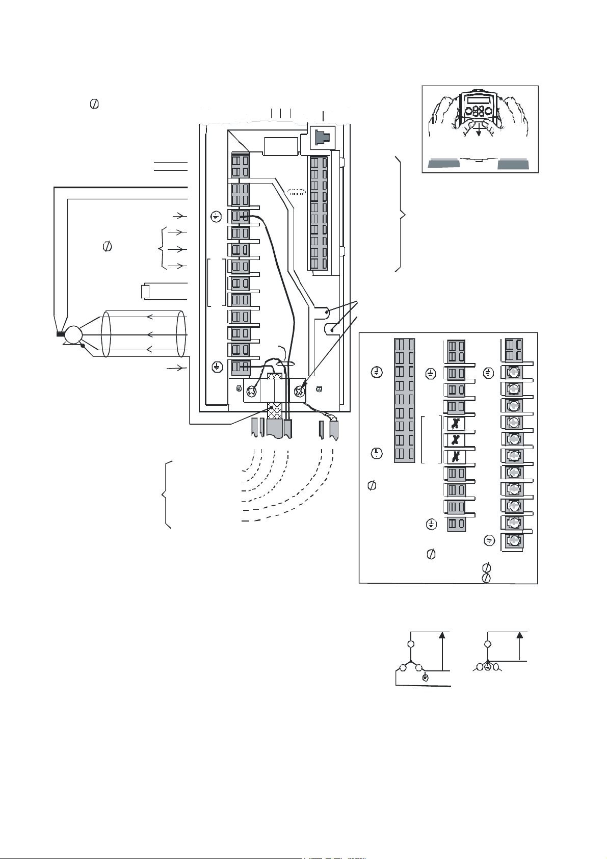
Connection Diagram
Frame 2
3 380-460V ac
(see Power Terminal Variations
inset for other frame sizes)
free
Volt Contacts
Motor Thermistor
Supply Prot ective Eart h/ Gr ound
380-46 0V ac
3
ext ernal b rake resis tor
(400V unit only)
M
Motor Protective Earth/Ground
screen
Installing the Drive 3-3
RS232
port
(fut ure op tio n)
13 12 11
fix cable
tie here
RL1A
RL1B
TH1A
TH1B
See Note 1
See
Note 2
L1
L2/N
L3
DC+
DBR
M1/U
M2/V
M3/W
use
two
separate
p rot ec t iv e
earth
wires
P3
To remove the Terminal Cover
press her e and slide down
10
DIN4/ DOUT 2
9
DIN3/ DOUT 1
8
DIN2
7
DIN1
6
+24V
5
AOUT1
4
+10V REF
3
AIN2
2
AIN1 *
1
0V
Wire Retain ers
Scre en Ear th/G roun d
TH1A
TH1B
Refer to Chapter 12: «Applications»
for specific cont rol wiring for each
Application
* If AIN1 is not used, connect to 0V
TH1A
TH1B
TH1A
TH1B
L1
1 : RL1 A, RL1B
Volt-free relay terminals can
be us ed a s ei t her `l iv e ’ or S ELV.
2 :TH1A, TH1B
Motor thermis tor connections are
regarded as a `live circuit’ and
mu s t no t be con n e ct e d to SELV ci rc uits .
Connect the 0V/COMMON t o protective earth/ground.
*
In a system comprisi ng more t han on e co ntrol ler,
connect the 0V/COMMON signals and join to
pr otec ti ve ear th/ gr oun d a t one poi nt onl y.
This is mandatory to meet the EMC spec ification stated.
Wiring Instructions
1 Remove the terminal cover from the drive.
2 Loose n the motor cable screen cla mp.
3 Connect the powe r supp ly cable, moto r cable and co ntro l c a bl es (if required ) .
4 Fast en the motor cable in place with the motor ca ble screen clamp.
Secure any control cable screen connections under the right hand screw.
Frames 2 & 3 only : Secure control cables under the wire retainers.
5 Connect t he the rmisto r an d u ser-rel ay i f re quired.
Frames 2 & 3 only: connect the dynamic brake if required (3 phase units only).
6 Us e a cable t ie an d secure al l the con trol cab le s and user — rel ay cables (i f fitte d)
as close to the control terminals as possible.
7 Co nnect the ancillary eq ui pment a s shown, for exampl e, an externa l br a ke resi stor.
8 Re-fit the terminal cover.
IMPORTANT:
Note that the 650 unit must be permanently earthed using two independent protective earth/ground incoming supply conductors.
screen and
connections
only
earth wire
shown for
clarit y
Motor Screen Earth/Ground
Dynamic Brake Cab le
Ther mi stor Cabl e
Motor Cable
Supply Cable
User Relay Cable
Cont rol C ables
L2/N
M1/U
M2/V
M3/W
Frame 1
1
220-240V ac
Power Terminal
Variations
Non-ea rth referenced
L1
L2/N
L3
DC+
DBR
M1/U
M2/V
M3/W
Frame 2
1 220-24 0V ac
IT
supply
The dri ve is s uitabl e for use with earth
refer enced supp lies (T N) and non -ea rth
refer enced supp lies (IT) when
fitted with an internal ac supply EMC filter.
L1
L2
L3
DC+
DBR
—
DC
M1/U
M2/V
M3/W
Frame 3
3 220-24 0V ac
3 380-46 0V ac
TN
Earth r eferenced
supply
650 Series AC Drive

3-4 Installing the Drive
Control Wiring Connections
Terminal
(SELV)
P3 P3 RS232 port for use with remote-mounted RS232 keypad or
RL1A User Relay Volt-free contact 0-250Vac/24Vdc 4A
RL1B User Relay Volt-free contact 0-250Vac/24Vdc 4A
10 DIN4/
9 DIN3/
8 DIN2 Direction – configurable digital input:
7 DIN1 Run – configurable digital input: 0V = Stop, 24V = Run 0-24V
6 +24V 24V – 24V supply for digital I/O 50mA maximum
5 AOUT1 Ramp Output – configurable analog output (10mA loading) 0-10V
4 10VREF 10V — 10V reference (10mA maximum loading) 10V
3 AIN2 Feedback – analog input 2 0-10V, 4-20mA
2 AIN1 Setpoint – analog input 1.
1 0V 0V — 0V reference for analog/digital I/O 0V
Description Application 1 Default Function
(for other Applications refer to Chapter 12: “Applications”)
programming PC
Configurable digital input/output
DOUT2
DOUT1
Not Stop (input):
0V = No latching of Run (DIN1), 24V = Run latched
Jog – configurable digital input:
0V = Stop, 24V = Jog
0V = Forward, 24V = Reverse
If AIN 1 is not used, connect to 0V.
Power Wiring Connections
Range
—
0-24V source open
collector 50mA
maximum
0-24V
0-24V
0-10V
Terminal Description Function Range
200V 1-Phase 200V/400V 3-Phase
TH1A Thermistor Connection to motor
thermistor
TH1B Thermistor Connection to motor
thermistor
Reference
Terminal
L1 Power Input Single and three
L2/N
L2
L3 Power Input Three phase live
DC- No user connection
DC+ Dynamic
DBR Dynamic
M1/U
M2/V
M3/W
Power Input Single phase neutral
Brake
Brake
Motor
Outputs
Reference
Terminal
Supply protective earth (PE). This terminal must be connected to a protective (earth)
ground for permanent earthing.
phase live
connection
(or L2 three phase
live connection)
connection
Connection to
external brake
resistor
Connection to
external brake
resistor
Connection for
motor
Supply protective earth (PE). This terminal must be connected to a protective (earth)
ground for permanent earthing.
It is good practice to protect motors by fitting temperature
sensitive resistors. A typical resistance (up to a reference
temperature of 125°C) is 200Ω, rising rapidly to 2000Ω above
this temperature. Connect devices in series between TH1A and
TH1B. Link the terminals if temperature sensors are not used.
220/240V ac ±10% rms with
respect to L2/N. 50-60Hz
(IT/TN)
220/240V ac ±10% with
respect to L1. 50-60Hz
(IT/TN)
Not applicable 220/240V or 380/460V ac
Not applicable Frame 2 (high volt only) & 3.
Not applicable Frame 2 (high volt only) & 3.
Motor rated at:
0 to 220/240V ac
0 to 240Hz
220/240V or 380/460V ac
±10% rms with respect to L2, L3
phase-to-phase. 50-60Hz
(IT/TN)
220/240V or 380/460V ac
±10% with respect to L1, L3.
50-60Hz (IT/TN)
±10% with respect to L1, L2.
50-60Hz (IT/TN)
See “Internal Dynamic Brake
Switch” table
See “Internal Dynamic Brake
Switch” table
Motor rated at:
0 to 220/240V or 380/460V ac
0 to 240Hz
650 Series AC Drive
Installing the Drive 3-5
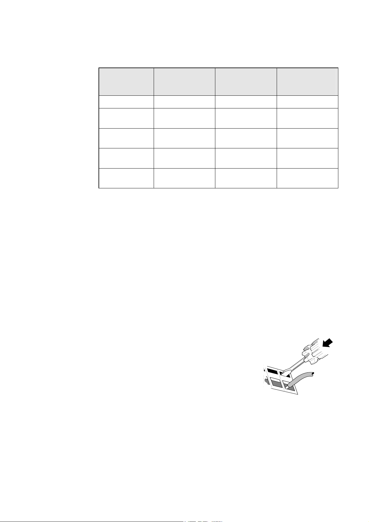
Terminal Block Acceptance Sizes
Wire sizes should be chosen with respect to the operating conditions and your local National
Electrical Safety Installation Requirements. Local wiring regulations always take precedence.
Frame Size Power Terminals
(maximum wire size)
Brake Terminals
(maximum wire size)
Thermistor/Control
Terminals
(maximum wire size)
Frame 1 2.5mm2/12 AWG Not Applicable 2.5mm2/12 AWG
Frame 2
200V
Frame 2
400V
Frame 3
230V
Frame 3
400V
2.5mm
2.5mm
6.0mm
6.0mm
2
/12 AWG Not Applicable 2.5mm2/12 AWG
2
/12 AWG 2.5mm2/12 AWG 2.5mm2/12 AWG
2
/10 AWG 6.0mm2/10 AWG 2.5mm2/12 AWG
2
/10 AWG 6.0mm2/10 AWG 2.5mm2/12 AWG
Power Wiring
Note: For specified EMC emission and immunity performance, install to EMC Installation
Instructions. Refer to Chapter 10: “Certification for the Drive” — for more information
Terminal tightening torque for Frame 3 power connections is 20 lb.in (2.26Nm).
Protect the incoming mains supply using the specified fuse, or RCD circuit breaker Type B.
IMPORTANT: We do not recommend the use of circuit breakers (e.g. RCD, ELCB, GFCI), however,
where their use is mandatory, they must:
• Operate correctly with dc and ac protective earth currents (i.e. type B RCDs as in
Amendment 2 of IEC755).
• Have adjustable trip amplitude and time characteristics to prevent nuisance tripping
on switch-on.
Control Wiring
Control wiring of between 0.08mm2 (28AWG) and 2.5mm2 (12AWG) can be used. Ensure all
wiring is rated for the highest system voltage. All control terminals are SELV (Safe Extra Low
Voltage), i.e. double-insulated from power circuits.
Using Cage Clamp Terminals
Strip the wire insulation to 5-6mm (0.20-0.24 inches), or
alternatively use wire-crimps. Insert a flat-bladed screwdriver,
maximum blade size 3.5mm. The cage provides the correct
force for a secure connection.
IMPORTANT: DO NOT lever or turn the screwdriver.
650 Series AC Drive
3-6 Installing the Drive
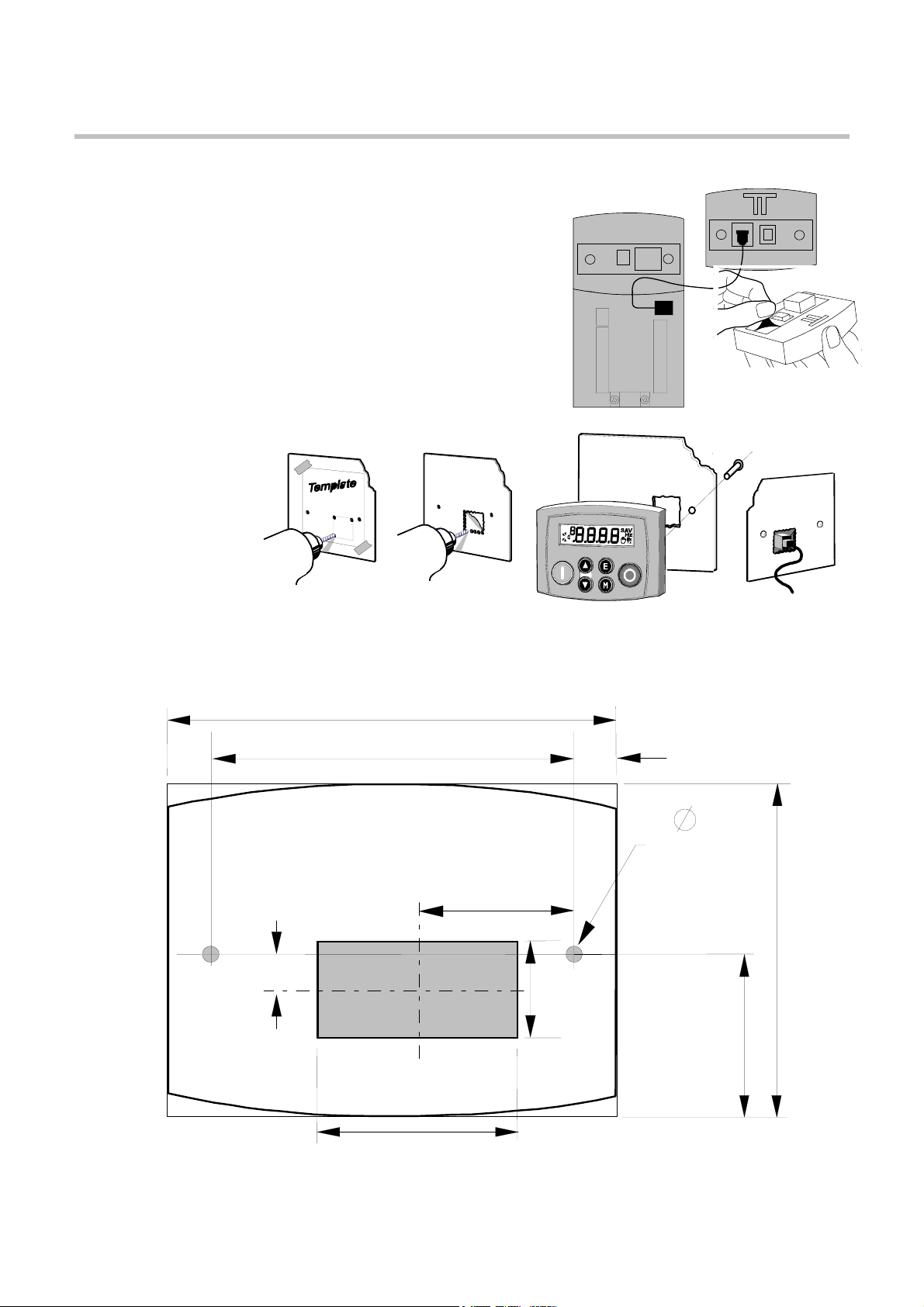
Optional Equipment
Fitting the Remote 6511 Keypad
You can remote-mount the drive-mounted Keypad using:
• the (optional) RS232 (P3) port located under
the terminal cover
• A standard P3 lead, Parker SSD Drives’ Part
Number CM057375U300, which is used to
connect the Keypad to the drive.
Two self-tapping screws are provided with the
Keypad. Remove the protective film from the
gasket. An enclosure rating of IP54 is achieved
for the remote Keypad when correctly mounted.
Assembly Procedure
1
P3
21
3
4
Cut-out Dimensions
The drawing below can be photocopied actual size (100%) and used as a template.
72mm
±
0.5
58
mm
Template
7mm
3.5
±
0.5
mm
15.5
±
mm
1
0
26mm
±
0.5
25
mm 5.5
Cut-out
±
0.5
0
P3
mm
54mm
32
2
±
mm
0
650 Series AC Drive

Installing the Drive 3-7
Fitting the Remote 6521/6901/6911 Keypad
The 6052 Mounting Kit is required to remote-mount a 6521 Keypad. An enclosure rating of
IP54 is achieved for the remote Keypad when correctly mounted using the 6052 Mounting Kit.
6052 Mounting Kit Parts for the Remote Keypad
Tools Required
No. 2 Posidrive
screwdriver.
Assembly Procedure
Cutout Dimensions
An actual size template is provided with
the Keypad/6052 Mounting Kit.
Figure 3-1 Mounting Dimensions for
the Remote-Mounted Keypad
6521/6901/6911
650 Series AC Drive
6901
The 6901/6911 keypad,
supplied with 690+
products, may be
remote mounted and
connected to the 650V
drive in the same way.
3-8 Installing the Drive
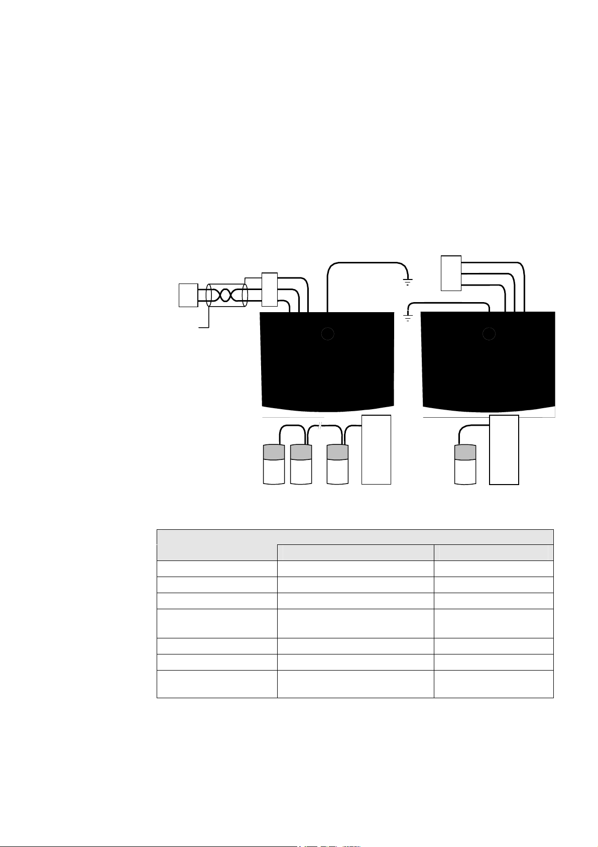
RS485/RS232 Communication Module
You can create a network of drives by linking a Master (PC/PLC) to one or more 650 drives
fitted with this module.
Plug this Communication Module on to the front of the 650 drive, replacing the keypad.
It converts signals from the host 650 drive into RS485 or RS232, and vice versa, so that
information can be shared between the Master and 650 drive(s).
Wiring is very simple — all connections are SELV (Safe Extra Low Voltage). Select to use
RS485 or RS232 by wiring to the appropriate terminal on the module.
Note: RS485 and RS232 terminals cannot be used simultaneously.
We recommend you ground the module to the system earth using the Functional Earth terminal.
PC/PLC
9-Way / 25-Way
D-Type
Connector
B
A
To PC/PLC
Chassis
650 Drive
with
Module
Scn
B
A
Functional
Earth
PC/PLC
9-Way or 25-Way
D-Type Connector
0V
Tx
Rx
PC/PLC
Master
Drive Drive Drive
master to single/multiple slave
RS485 Connections
PC/PLC
Master
Drive
master to single slave only
RS232 Connections
Wiring Specifications
RS485 Connections RS232 Connections
Network Type
Connections
Signal Levels
Receiver Input
Impedance
Maximum Cable Length
Maximum Baud Rate
Maximum Number of
Units
2-Wire Shielded Twisted-Pair 3-Wire Un-Shielded Cable
A=RxA/TxA, B=RxB/TxB, Shield Rx, Tx, Ground (0V)
To RS485 Standard To RS232 Standard
¼ Unit Load
3 kΩ minimum
7kΩ maximum
1200m (4000ft) 3 metres
57.6kbaud 57.6kbaud
32 including slaves and masters
2: 1 master and 1 slave
only
650 Series AC Drive

LED Indications
The module has three LEDs providing diagnostic
information about the 650 host drive’s ‘Health’,
‘Receive’ and ‘Transmit’ activity.
HEALTH = Green, Rx = Red, Tx =Red
LED Name LED Duty Drive State
HEALTH
Rx
Tx
SHORT FLASH
EQUAL FLASH
ON
LONG FLASH
OFF
INTERMITTENT
INTERMITTENT
Re-configuration, or corrupted non-volatile
memory at power-up
Tripped
Healthy
Braking
No drive power, or serious hardware fault
Indicates activity on the ‘receive’ line carrying
data from the Master
Indicates activity on the ‘transmit’ line carrying
data to the Master
Installing the Drive 3-9
Configure the Drive
Before the module can be used you must configure the drive to your system. Set-up the
parameters in the SERIAL menu as appropriate. Refer to Chapter 6: «Programming Your
Application» — SET::SERL Menu, parameters
For Tag number information refer to the 650 Software Product Manual, available on the Parker
SSD Drives website: www.SSDdrives.com.
Note: This Option can only be used on drives using software version 4.1 or higher.
S
SE01 to SSE08.
650 Series AC Drive
3-10 Installing the Drive
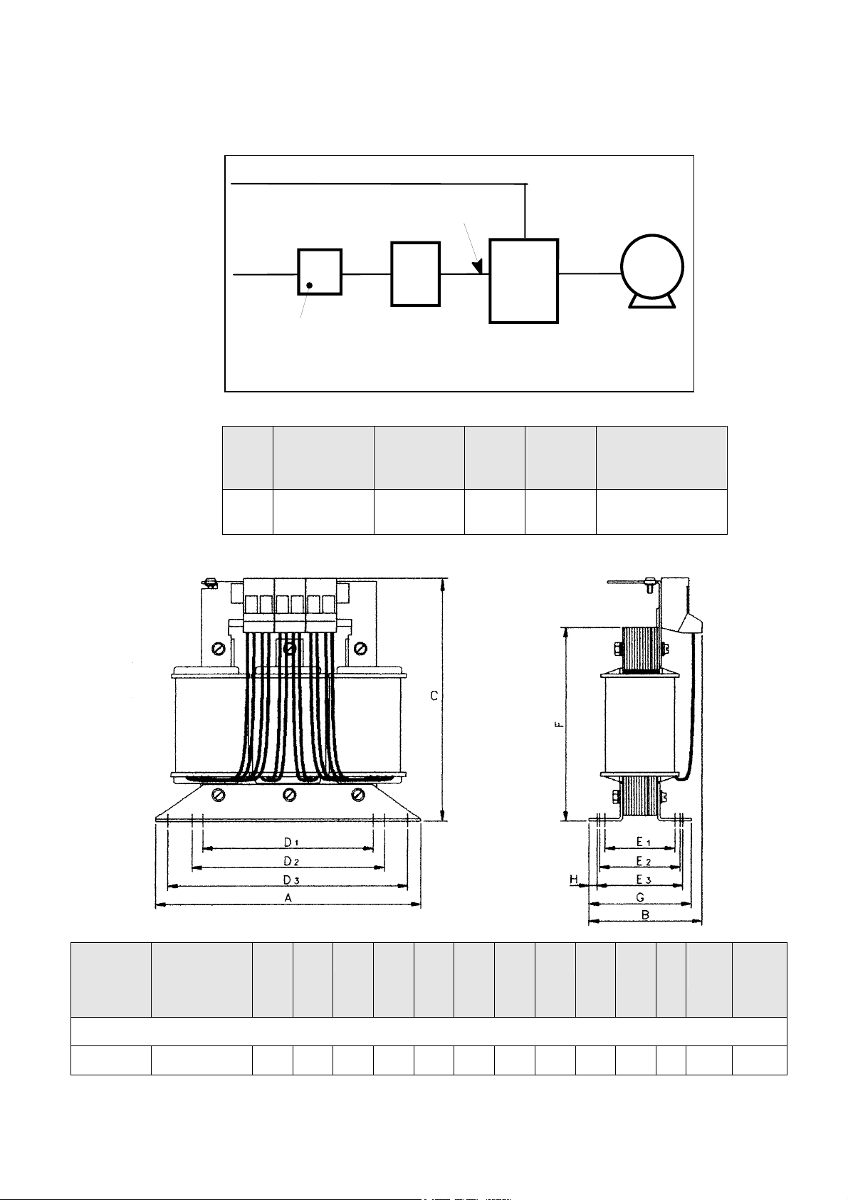
Line Choke
Cables are considered to be electrically sensitive, clean or noisy. A line choke is used to reduce
harmonic emission to meet the limits of EN61000-3-2.
signal/control cable
(sensitive)
power
supply
cable
(clean)
fuse or suitable
circuit breaker
(RCD not
recommended)
The choke is for use on the following drive:
line
choke
(noisy)
drive
motor
cable
(noisy)
motor
Phase Drive Nominal
Input Voltage
(V)
3 400 0.37/0.5 6 4.88
Drive Power
(kW/hp)
Rated
Current
(Aeff)
Rated
Inductivity
(mH)
Choke
Part Number
CO467763U003
(Europe)
Rated
Current
(Aeff)
6 4.88 148 76 151 90 100 136 39 45 49 110 69 M4 2.1/
Rated
Inductivity
(mH)
* dimension is dependent of the air gap
A
B C D1 D2 D3 E1 E2 E3 F* G Fixing
(mm)
650 Frame 2, 3-phase, 400V, 0.37kW/0.5Hp
Weight
Screws
(kg/lbs)
650 Series AC Drive
Operating the Drive 4-1
1OPERATING THE DRIVE
Pre-Operation Checks
WARNING!
Wait for 5 minutes after disconnecting power before working on any part of the system or removing the
terminal cover from the drive.
Initial checks before applying power:
• Check for damage to equipment.
• Mains power supply voltage is correct.
• Motor is of correct voltage rating and is connected in either star or delta, as appropriate.
• Check all external wiring circuits — power, control, motor and earth connections.
Note: Completely disconnect the drive before point to point checking with a buzzer, or when checking
insulation with a Meggar.
• Check for loose ends, clippings, drilling swarf etc. lodged in the drive and system.
• If possible check that the motor can be turned freely, and that any cooling fans are intact and free from obstruction.
Ensure the safety of the complete system before the drive is energised:
• Ensure that rotation of the motor in either direction will not cause damage.
• Ensure that nobody else is working on another part of the system which will be affected by powering up.
• Ensure that other equipment will not be adversely affected by powering up.
Prepare to energise the drive and system as follows:
• Remove the supply fuses, or isolate using the supply circuit breaker.
• Disconnect the load from the motor shaft, if possible.
• If any of the drives control terminals are not being used, check whether these unused terminals need to be tied high
or low.
• If the motor thermistor terminals are not connected to a motor thermistor, connect these terminals together.
• Check external run contacts are open. Check external speed setpoints are all zero.
Re-apply power to the drive and system
Initial Start-up Routines
Note: Refer to Chapter 5: “Using the Keypad” to familiarise yourself with the keypad’s
indications, and how to use the keys and menu structure.
!
!
IMPORTANT
When power
is applied to
IMPORTANT
the drive in
On power-up
Remote
in Remote
Control, it will
Control, the
immediately
drive will
start running if
immediately
the RUN
start running if
signal is
the RUN
active.
nal is
si
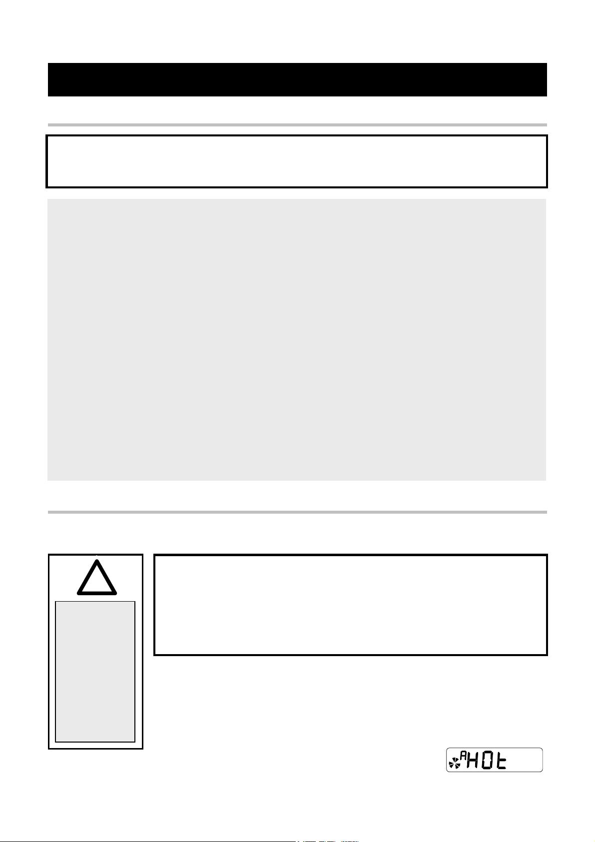
Note: If during the start-up routine the display shows either an alarm
The drive can be started in either Remote Control or Local Control. By default, the drive will
start in Local Control.
These routines assume that the drive’s control terminals are wired as shown in the Control
Wiring Connections in Chapter 3.
Connected in this way, a positive setpoint will rotate the motor in a clockwise direction when
viewed down the shaft, looking toward the motor.
(indicated by the letter “A”) or a flashing Warning message,
refer to Chapter 7: “Trips and Fault Finding”.
Unpredictable motion, especially if motor parameters are incorrect.
Ensure no personnel are in the vicinity of the motor or any connected machinery.
Ensure that machinery connected to the motor will not be damaged by
Ensure that the emergency stop circuits function correctly before running the motor
WARNING!
unpredictable motion.
for the first time.
A typical alarm
650 Series AC Drive
4-2 Operating the Drive
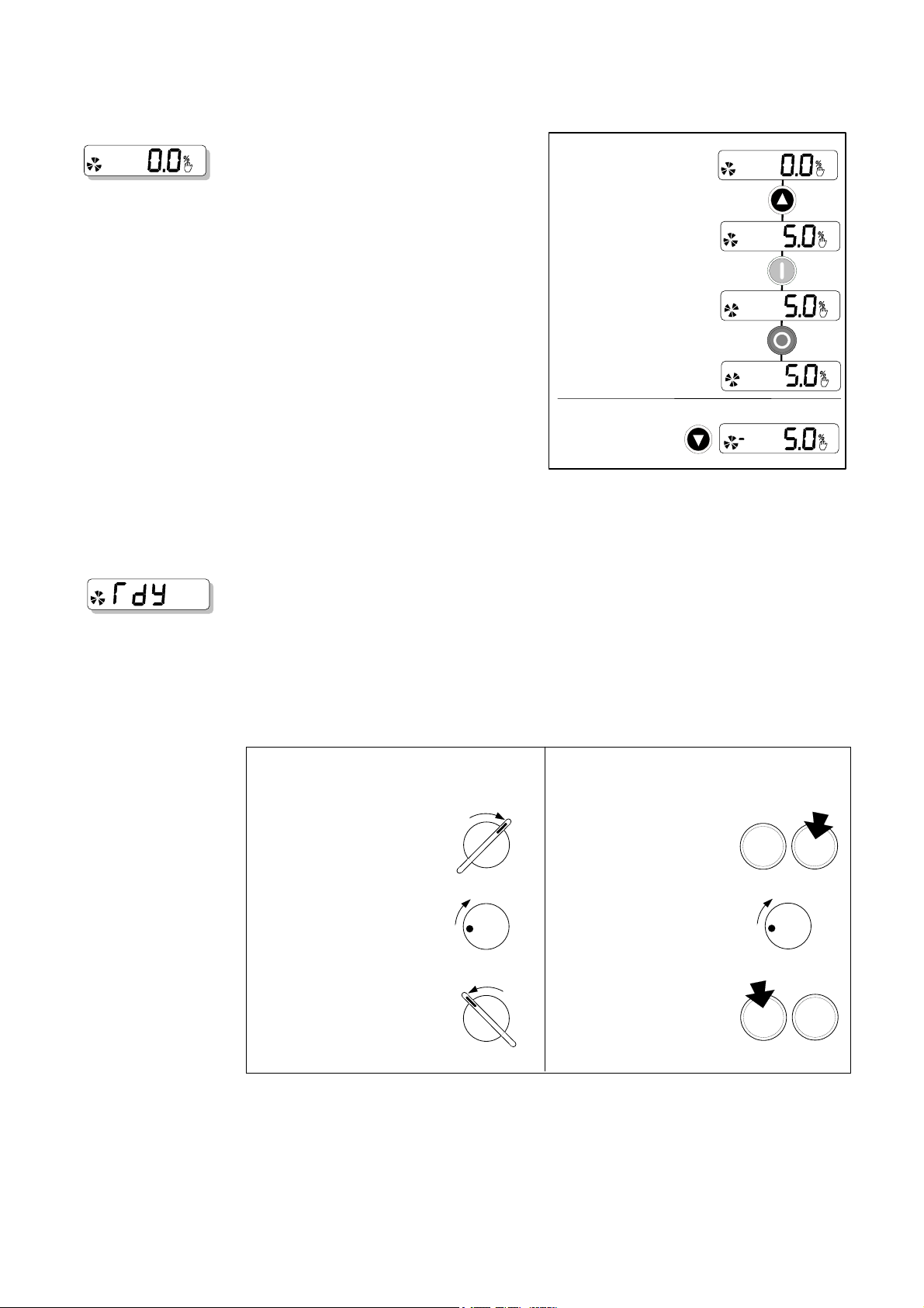
Local Control Operation
LOCAL
This is the simplest method of operating the
drive. Connect the keypad to the drive and
power -up the unit.
The drive will display the Local screen. If not,
refer to Chapter 5 and select Local Control.
Follow the instructions opposite to start and
stop the motor.
Reverse: Instead of setting a negative
setpoint, you can reverse the motor direction
by pressing STOP + T, or START + T.
To change the direction to forwards, (the
normal direction), press STOP + S or
START + S.
LOCAL
Press to apply a small setpoint
(see Reverse below)
Press to start the motor
and it will ramp to the setpoint
Press to stop the motor
and it will ramp to zero
Note that the Setpoint parameter will not
change sign to indicate this change, however
the rotating indicator on the MMI will show
the direction.
Reverse
From zero, release
and press again for
a negative setpoint
We recommend that you use the STOP key commands if the motor is stopped, and the START
key commands if the motor is running. The keys should be pressed and released together.
Remote Control Operation
REMOTE
IMPORTANT: Ensure that the speed potentiometer is set to zero.
Connect the keypad to the drive and power-up the unit.
The drive will display the Local screen. Refer to Chapter 5 and select Remote Control.
Follow the instructions below to start and stop the motor using your control panel.
Reverse the motor’s direction of rotation using the DIN2 connection (0V = forward, +24V =
reverse). Alternatively, swap two of the motor phases (WARNING: Disconnect the mains
supply first).
Single Wire Starting Push-button Starting
STOP START
Close the RUN switch (DIN1)
Apply a small speed setpoint
and the motor will ramp to
the setpoint
Open the RUN switch (DIN1)
and the motor will ramp to zero
RUN SWITCH
5
0
POTENTIOMETER
STOP START
RUN SWITCH
Press the Start button
(DIN1)
Apply a small speed setpoint
and the motor will ramp to
100
the setpoint
Press the Stop button
(DIN4/DOUT2)
and the motor will ramp
to zero
(Applications 1 & 5 only)
STOP
PUSHBUTTONS
0
POTENTIOMETER
STOP
PUSHBUTTONS
START
5
100
START
The installation of your drive is now complete:
The drive will operate as an open-loop drive. It is programmed to control an induction motor of
equivalent power, current, and voltage rating to the drive.
The drive’s default parameters will operate effectively under most circumstances, however you
may wish to refer to Chapter 6 to tune the drive to your system.
650 Series AC Drive
Loading…
Серия универсальных преобразователей AC650/AC650V предназначена для использования в различных областях промышленности: вентиляционные системы, подъемные механизмы, химическая промышленность, автопромышленность, деревообработка, производство стройматериалов, обработка металла.
Отличительные особенности:
- ЖК-дисплей с подсветкой
- ПИД — регулирование
- Встроенный ЭМС-фильтр
- Защищенная паролем клавиатура
- Встроенный тормозной резизстор
- Степень защиты IP20
- Модуль клонирования 6514/00
- TTL-панель управления 6511/TTL/00
- Запрограммированные макросы приложений: насосы, вентиляторы, компрессоры, конвейеры, станки
- Векторный тип управления
Дополнительная информация:
Переход в раздел технической документации
Запросить дополнительную информацию и цены
Parker 650 Series Controller PDF User Guides and Manuals for Free Download: Found (3) Manuals for Parker 650 Series Device Model (Product Manual, Safety Booklet & Quickstart, Easy Start Manual)
The Parker 650 Series is a notable offering from one of the leading manufacturers in the industry. Known for its reliability and innovative features, this series has captured the attention of professionals across various sectors. The product line is designed to meet the high standards of engineering performance, making it an attractive option for those seeking precision and durability.
One of the standout aspects of the Parker 650 Series is its versatility. Engineers and project managers appreciate the adaptability of this product in different applications. Whether you’re working in industrial settings, automotive environments, or any other technical domain, the 650 Series provides solutions that can be tailored to meet specific needs. This adaptability is complemented by its robust construction, ensuring that it can withstand the rigors of daily use.
The design of the Parker 650 Series is both functional and ergonomic. The intuitive layout allows for straightforward operations, which is essential in high-pressure environments where time is of the essence. This user-friendly aspect doesn’t compromise its technical capabilities. The series is packed with advanced features that enhance its overall performance. These include:
- Highly efficient functionality that reduces downtime.
- Innovative control systems that improve precision in handling.
- Durable materials that resist wear and tear.
Another significant benefit of the Parker 650 Series is its energy efficiency. In today’s world, where sustainability is paramount, this series stands out by providing products that not only perform well but also minimize energy consumption. This feature does not only contribute to lower operational costs; it also aligns with broader environmental goals, making it a responsible choice for businesses.
Customer feedback on the Parker 650 Series has been largely positive, reflecting high satisfaction rates among users. Many commend its reliability, stating that it consistently delivers results without frequent maintenance. This reduces operational interruptions, allowing teams to focus on their core responsibilities.
Moreover, the technical support provided by Parker is exceptional. With a dedicated team ready to assist clients in troubleshooting and optimizing their use of the 650 Series products, the overall experience is enhanced significantly. This level of customer service fosters trust and loyalty, which are vital in today’s competitive market.
In summary, the Parker 650 Series represents a perfect blend of innovation, efficiency, and reliability. For professionals seeking top-tier equipment that can elevate their projects, this series provides a compelling solution. Its adaptability across multiple applications, combined with exceptional customer support, makes it a wise investment for any organization focused on quality and performance.
Скачать
Compumotor
OEM650/OEM650X
OEM350/OEM350X
Drive and Drive/Indexer
User Guide
Compumotor Division
Parker Hannifin Corporation
p/n 88-013157-02 A
RE
MO
TE
RE
F
CU
RR
EN
T
DU
MP
VD
C+
VD
C-
A+
A-
B+
B-
Co
mp
um
oto
r
OEM
OEM
s
e
r
i
e
s
DRI
V
E
D
R
IV
E
DRIVE
D
R
IV
E
POWER
FAULT
На этой странице вы можете совершенно бесплатно скачать Инструкция по эксплуатации Parker Products OEM650.
У документа PDF Инструкция по эксплуатации 58 страниц, а его размер составляет 373 Kb.
Читать онлайн Сетевые карты Parker Products OEM650 Инструкция по эксплуатации
Google Ads:
Скачать файл PDF «Parker Products OEM650 Инструкция по эксплуатации» (373 Kb)
Популярность:
5171 просмотры
Подсчет страниц:
58 страницы
Тип файла:
Размер файла:
373 Kb
Google Ads:
Google Ads: