
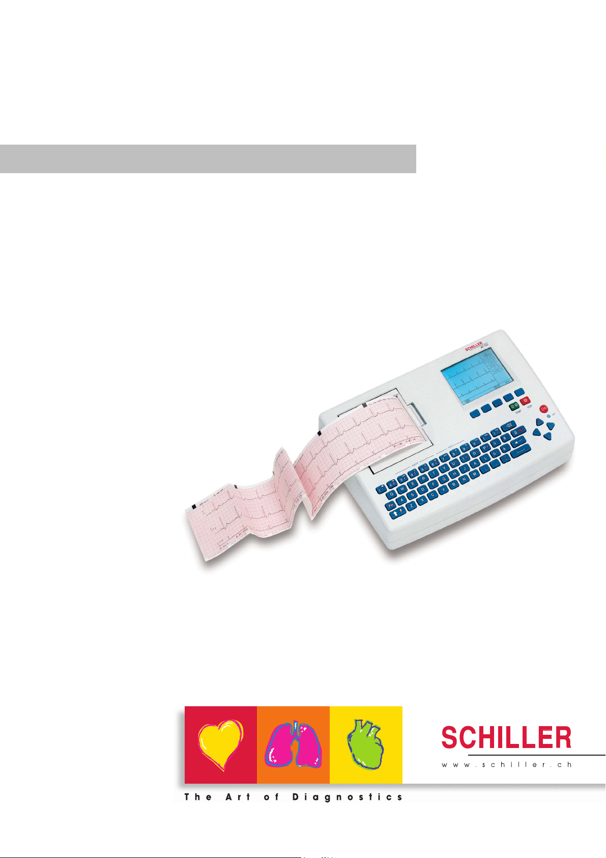
AT-101
AT-101
12-Channel ECG Unit
Art.-no.: 2.510526 Rev.: c *2.510526*
User Guide

Sales and Service Information
The SCHILLER sales and service centre network is world-wide. For the address
of your local distributor, contact your nearest SCHILLER subsidiary. In case of difficulty a complete list of all distributors and subsidiaries is provided on our internet
site: http://www.schiller.ch.
Sales information can also be obtained from:
sales@schiller.ch
Address Headquarters
SCHILLER AG Phone: +41 (0) 41 766 42 42
Altgasse 68 Fax: +41 (0) 41 761 08 80,
CH-6341 Baar, Switzerland E-mail: sales@schiller.ch
Web: www.schiller.ch
Artikel-Nr.: 2.510526 Rev.: c
Issue date: 25.05.05

AT-101
User Guide
Contents
1 Safety notes ……………………………………….3
1.1 Responsibility of the User ………………………………………….. 3
1.2 Intended Use ……………………………………………………………… 3
1.3 Organisational Measures…………………………………………….. 3
1.4 Safety-conscious Operation………………………………………… 4
1.5 Safety Facilities ………………………………………………………….. 4
1.6 Operation with other Devices ………………………………………. 5
1.7 Maintenance……………………………………………………………….. 5
1.8 Safety Symbols and Pictograms………………………………….. 6
1.8.1 Used symbols in this document ………………………………………………… 6
1.8.2 Used symbols on the device …………………………………………………….. 7
1.9 Terms of Warranty………………………………………………………. 8
2 Introduction ……………………………………….9
2.1 Features……………………………………………………………………… 9
2.1.1 Standard Features ………………………………………………………………….. 9
2.1.2 Optional Features……………………………………………………………………. 9
2.2 Operating Philosophy Overview ………………………………… 10
2.2.1 Initiating Functions or Tasks …………………………………………………… 10
2.2.2 Main Components of the AT-101 …………………………………………….. 11
2.2.3 Back Panel…………………………………………………………………………… 11
2.3 Keypad……………………………………………………………………… 12
2.4 LCD Screen ………………………………………………………………. 14
3 Operation ………………………………………… 15
3.1 Start-up and Initial Preparation ………………………………….. 15
3.1.1 Connecting AT-101 ……………………………………………………………….. 15
3.1.2 Battery Operation………………………………………………………………….. 16
3.1.3 Switching ON and OFF ………………………………………………………….. 16
3.1.4 Isolating the Mains Supply ……………………………………………………… 16
3.1.5 Potential Equalisation…………………………………………………………….. 16
3.1.6 Inserting Printing Paper …………………………………………………………. 17
3.1.7 LCD contrast adjustment………………………………………………………… 17
3.2 Entering Patient Data ………………………………………………… 18
4 Resting ECG ……………………………………. 19
4.1 Electrode Placement …………………………………………………. 19
4.2 Further Lead Combinations……………………………………….. 21
4.2.1 Nehb Leads………………………………………………………………………….. 21
4.2.2 Electrode Positions for Additional Leads…………………………………… 22
Art.-no.: 2.510526 Rev.: c
4.2.3 Electrodes and Neutral Electrodes Identification and
Colour Code…………………………………………………………………………. 23
4.3 Skin/Electrode Resistance…………………………………………. 24
4.3.1 High Electrode Resistance Indication ………………………………………. 24
4.3.2 Electrode and Patient cable Check (Lead Test)…………………………. 24
4.4 Modes of Operation and Procedural
Page 1

AT-101
Overview…………………………………………………………………… 25
4.4.1 Automatic Mode……………………………………………………………………. 26
4.4.2 Manual Mode ……………………………………………………………………….. 27
4.4.3 Screen (and Manual Printout) Settings …………………………………….. 28
4.5 Memory (option)………………………………………………………… 30
4.5.1 Transmitting the Recordings…………………………………………………… 31
5 Setup ………………………………………………..32
5.1 Entering the SETUP Menu …………………………………………. 32
5.1.1 Navigating in the Setup Screens……………………………………………… 32
5.2 ECG Settings…………………………………………………………….. 33
5.2.1 Automatic Format 1 and 2 Internal Printer ………………………………… 34
5.2.2 Automatic Format 1 and 2 External Printer……………………………….. 35
5.2.3 Filters ………………………………………………………………………………….. 36
5.2.4 Interpretation (Only with version C) …………………………………………. 37
5.2.5 Leads ………………………………………………………………………………….. 38
5.2.6 General (only with version m = Memory) ………………………………….. 38
5.3 System Settings………………………………………………………… 39
5.3.1 Unit……………………………………………………………………………………… 40
5.3.2 Communication ……………………………………………………………………. 41
5.3.3 Communication with SCM………………………………………………………. 42
5.3.4 Test and Information……………………………………………………………… 43
5.3.4.1 Print Setup …………………………………………………………………………… 44
5.3.4.2 Communications Test ……………………………………………………………. 45
5.3.4.3 Installing New Software Options (Upgrade)………………………………. 45
5.3.4.4 Update the Software ……………………………………………………………… 45
5.3.4.5 Default Settings…………………………………………………………………….. 46
6 Care & Maintenance ………………………….47
6.1 Service interval …………………………………………………………. 47
6.2 Communication (RS-232) Test……………………………………. 47
6.3 Maintenance interval for the battery …………………………… 48
6.3.1 Charging the battery …………………………………………………………….. 48
6.3.2 Battery disposal ……………………………………………………………………. 48
6.4 Changing the fuse and mains voltage ………………………… 49
6.5 Cleaning……………………………………………………………………. 50
6.5.1 Cleaning the Casing………………………………………………………………. 50
6.5.2 Cleaning the Patient Cable …………………………………………………….. 50
6.5.3 Cleaning the Thermal Print Head…………………………………………….. 50
6.6 Replacing the Recording Paper …………………………………. 51
6.6.1 Thermal Paper Handling ………………………………………………………… 51
6.7 Fault-Finding …………………………………………………………….. 52
6.7.1 Accessories and Disposables …………………………………………………. 53
7 Technical Data ………………………………….54
7.1 System ……………………………………………………………………… 54
7.2 Technical Data for ECG……………………………………………… 55
7.3 Safety Standards ………………………………………………………. 56
8 Index ………………………………………………..57
Art.-no.: 2.510526 Rev.: c
Page 2
Safety notes 1
AT-101 User Guide Responsibility of the User 1.1
1 Safety notes
1.1 Responsibility of the User
V This device must only be used by qualified doctors or trained medical personnel.
V The numerical and graphical results and any interpretation given must be exami-
ned with respect to the overall clinical condition of the patient and the general recorded data quality.
V The indications given by this equipment are not a substitute for regular checking
of vital functions.
V Specify the competencies of the personnel for operation and repair.
V Ensure that personnel have read and understood these operating instructions. In
particular this chapter “safety notes» must be read and understood.
V Have damaged or missing components replaced immediately.
V The operator is responsible for compliance with all applicable accident prevention
regulations and safety regulations.
1.2 Intended Use
V The AT-101 is a 12-channel, ECG device used for the recording, analysis and
evaluation of ECG Recordings. Recordings made with the AT-101 can be used
as a diagnostic aid for heart function and heart conditions. The AT-101 is designed for indoor use and can be used for all patients of both sexes, all races, and
all ages.
V There is no danger for patients with pacemaker.
V Only operate the device in accordance with the specified technical data.
V The device is not designed for sterile use nor is it designed for outdoor use.
V Do not use this unit in areas where there is any danger of explosion or in the
presence of flammable gases such as anaesthetic agents.
V This unit is CF classified and defibrillation protected only when the original
patient cable is used. However, as a safety precaution when possible, remove
electrodes before defibrillation.
V This product is not designed for internal use.This product is not designed for di-
rect cardiac application.
1.3 Organisational Measures
V Before using the unit, ensure that an introduction regarding the unit functions and
the safety precautions has been provided by a medical product representative.
V Keep these operating instructions in an accessible place for reference when re-
quired. Make sure that they are always complete and legible.
V Observe the operating instructions and maintenance instructions.
V These operating instructions do not override any statutory or local regulations, or
Art.-no.: 2.510526 Rev.: c
procedures for the prevention of accidents and environmental protection.
Page 3
1 Safety notes
1.4 Safety-conscious Operation
1.4 Safety-conscious Operation
1.5 Safety Facilities
AT-101
V Make sure that the staff has read and understood the operating instructions — par-
ticularly the «Safety Notes» chapter.
V Do not touch the unit casing during defibrillation.
V To ensure patient safety, none of the electrodes including the neutral electrode,
nor the patient or any person with simultaneous patient contact, must come in
contact with conductive parts, even when these are earthed.
V Immediately report any changes that impair safety (including operating beha-
viour) to the person responsible.
V Do not place any liquids on the unit. If liquid should be spilled over the device,
immediately disconnect the device from the mains and wipe it. The device must
be serviced before reusing.
V Only connect the original SCHILLER patient cable to the patient socket.
V Operating the device without the correctly rated fuse, or with defective cables,
constitutes a danger to life. Therefore:
– Do not operate the unit if the earth connection is suspect or if the mains lead is
damaged or suspected of being damaged.
– Damaged cable connections and connectors must be replaced
immediately.
– The electrical safety devices, such as fuses, must not be altered.
– Ruptured fuses must only be replaced with the same type and rating as the ori-
ginal.
Page 4
Art.-no.: 2.510526 Rev.: c
Safety notes 1
AT-101 User Guide Operation with other Devices 1.6
1.6 Operation with other Devices
V Use only accessories and other parts recommended or supplied by SCHILLER
AG. Use of other than recommended or supplied parts may result in injury, inaccurate information and/or damage to the unit.
V Ancillary equipment connected to the analogue and/or digital interfaces must be
certified according to the respective IEC standards (e.g. IEC/EN 60950 for data
processing equipment and IEC/EN 60601-1 for medical equipment). Furthermore
all configurations shall comply with the valid version of the system standard IEC/
EN 60601-1-1. Everybody who connects additional equipment to the signal input
part or signal output part configures a medical system, and is therefore responsible that the system complies with the requirements of the valid version of the system standard IEC/EN 60601-1-1. If in doubt, consult the technical service department or your local representative.
– EC/EN 60601-1-1 states that the patient must remain at least 1.5 meters clear
of the unit. If this is not possible, a safety isolating transformer must be installed.
V Any other equipment used with the patient must use the same common earth as
the AT-101.
V Precautions must be observed when using high frequency devices. Use the spe-
cial high frequency SCHILLER patient cable to avoid possible signal interference
during ECG acquisition.
V There is no danger when using the ECG unit simultaneously with electrical stimu-
lation equipment. However, the stimulation units should only be used at a sufficient distance from the electrodes. If in doubt, the patient should be disconnected from the device.
V If the patient cable should become defective after defibrillation, an electrode be-
comes displaced, or an electrode resistance is too high, a lead-off indication is
displayed in the upper right part of the screen and an acoustic alarm given.
V If the device is a part of a medical system, the original SCHILLER patient cable
must only be used with, and connected to, the patient connector on the AT-101.
1.7 Maintenance
V Danger of electric shock! Do not open the device. No serviceable parts inside.
Refer servicing to qualified technician authorised by SCHILLER only.
V Before cleaning and to isolate the mains power supply, switch the unit off and dis-
connect it from the mains by removing the plug.
V Do not use high temperature sterilisation processes
(such as autoclaving). Do not use E-beam or gamma radiation sterilisation.
V Do not use solvent or abrasive cleaners on either the unit or cable assemblies.
V Do not, under any circumstances, immerse the unit or cable assemblies in liquid.
Art.-no.: 2.510526 Rev.: c
Page 5
1 Safety notes
1.8 Safety Symbols and Pictograms
1.8 Safety Symbols and Pictograms
1.8.1 Used symbols in this document
AT-101
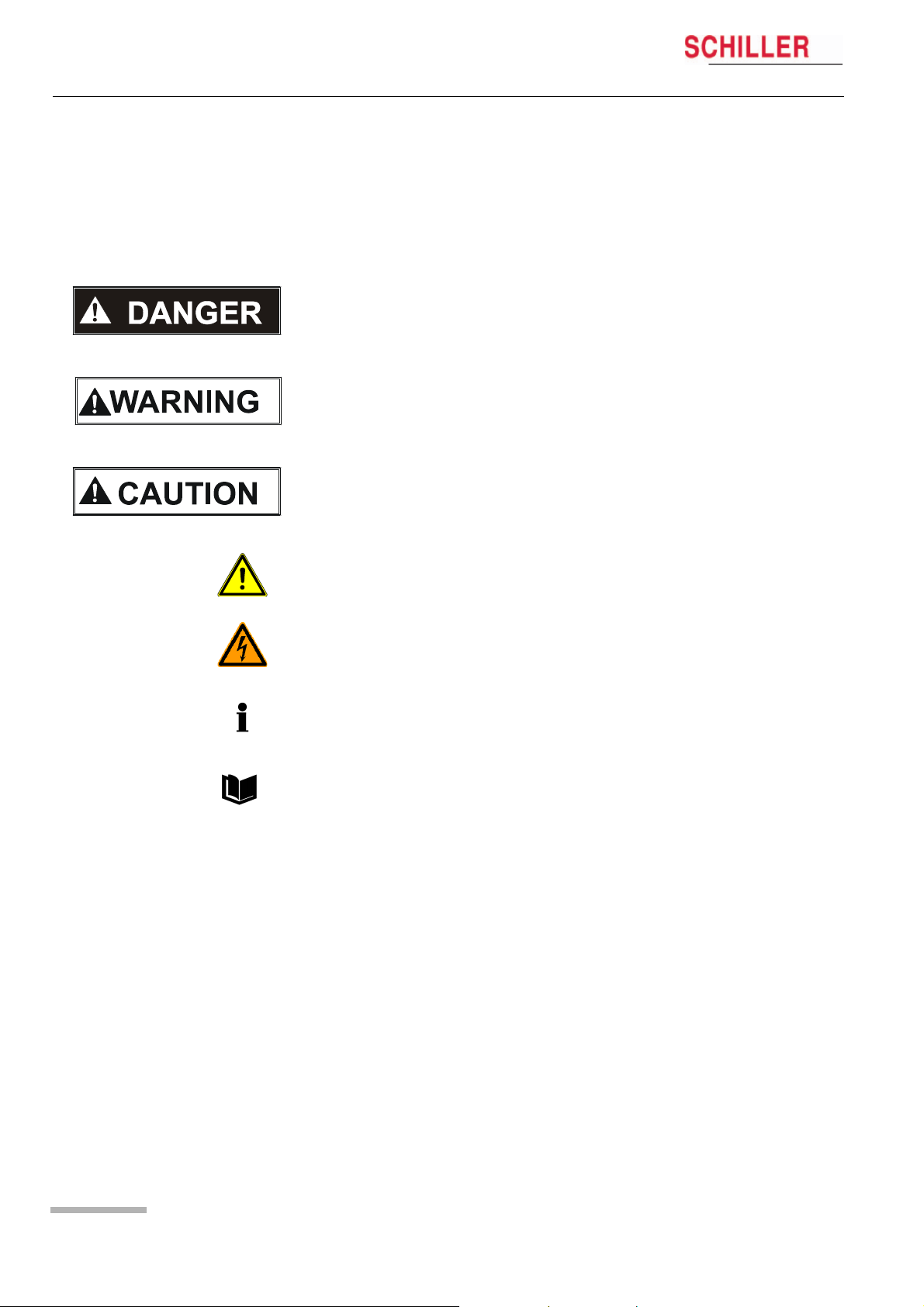
The safety level is classified according ANSI Z535.4. The following overview shows
the used safety symbols and pictograms used in this manual.
For a direct danger which could lead to severe personal injury or to death.
For a possibly dangerous situation, which could lead to heavy bodily injury or to death.
For a possibly dangerous situation which could lead to personal injury. This symbol is
also used to indicate possible damage to property.
For general safety notes as listed in this chapter.
Used for electrical dangers, warnings and other notes in regarding operation with electricity.
Note For possibly dangerous situations, which could lead to damages to property or
system failure. Important or helpful user information
Reference to other guidelines
Page 6
Art.-no.: 2.510526 Rev.: c
Safety notes 1
AT-101 User Guide Safety Symbols and Pictograms 1.8
1.8.2 Used symbols on the device
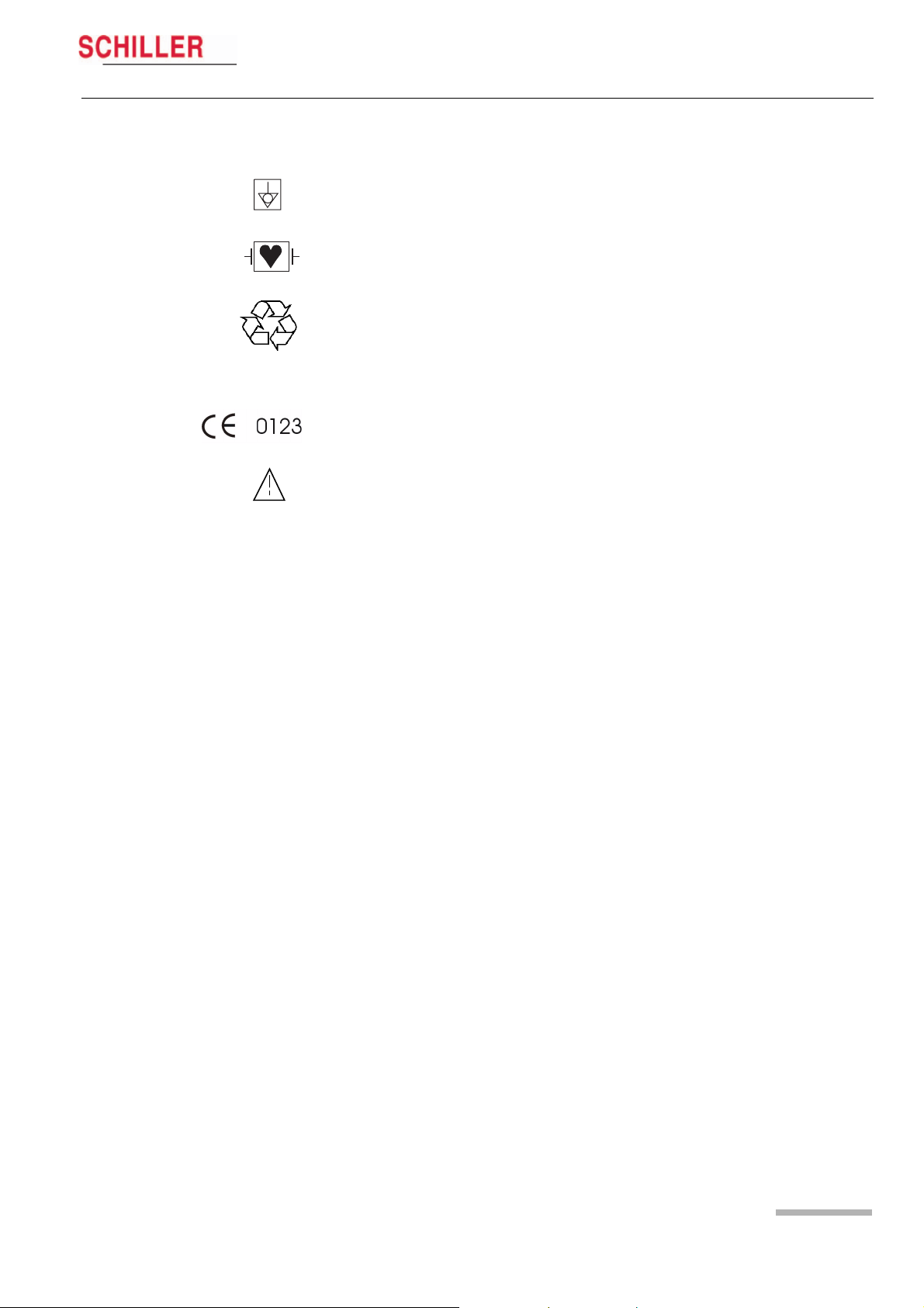
Potential equalization
CF symbol. This unit is classified safe for internal and external use. However, It is only
defibrillation protected when used with the original SCHILLER patient cable!
Inappropriate disposal can lead to environmental pollution.
Units/components and accessories no longer required can be returned to SCHILLER
AG for disposal. Alternatively, the unit should be disposed of in a municipally approved recycling centre.
Notified body of the CE certification (TÜV P.S.)
Attention: Consult accompanying documents.
Art.-no.: 2.510526 Rev.: c
Page 7

1 Safety notes
1.9 Terms of Warranty
AT-101
1.9 Terms of Warranty
The SCHILLER AT-101 is warranted against defects in material and manufacture for
the duration of one year (as from date of purchase). Excluded from this guarantee is
damage caused by an accident or as a result of improper handling. The warranty entitles free replacement of the defective part. Any liability for subsequent damage is excluded. The warranty is void if unauthorized or unqualified persons attempt to make
repairs.
In case of a defect, send the apparatus to your dealer or directly to the manufacturer.
The manufacturer can only be held responsible for the safety, reliability, and performance of the apparatus if:
• assembly operations, extensions, readjustments, modifications, or repairs are carried out by persons authorized by him, and
• the SCHILLER AT-101 and approved attached equipment is used in accordance
with the manufacturers instructions.
There are no Express or implied warranties which extend beyond the warranties hereinabove set forth. SCHILLER makes no warranty of merchantability or fitness for a
particulare purpose with respect to the product or parts therefof.
This equipment has been tested and found to comply with the limits for a class A digital device, pursuant to both Part 15 of the FCC (Federal Communications Commission) Rules and the radio interference regulations of the Canadian Department of
Communications. These limits are designed to provide reasonable protection against
harmful interference when the equipment is operated in a commercial environment.
This equipment generates, uses and can radiate radio frequency energy and, if not
installed and used in accordance with this instruction manual, may cause harmful interference to radio communications. Operation of this equipment in a residential area
is likely to cause harmful interference in which case the user will be required to correct
the interference at his own expense.
Page 8
Art.-no.: 2.510526 Rev.: c

Introduction 2
AT-101 User Guide Features 2.1
2 Introduction
2.1 Features
The SCHILLER AT-101 is a 12-channel ECG unit designed to record, display, and
analyse resting ECGs. The unit has been extensively researched to give an ergonomic, clear interface that‘s easy to use without compromising functionality. The AT-101
has the following features:
2.1.1 Standard Features
• Alphanumeric keypad and dedicated soft key interface for easy, user friendly
operation.
• Integral thermal quality printer with various user defined print format
options.
• Measurements and average cycles with automatic and manual printout of the recording.
2.1.2 Optional Features
• External printers
• ECG Interpretation
• Memory for up to 40 recordings
• Thrombolysis
• SCHILLER Communication modul (SCM) for data transmission to server via:
– Ethernet
– Modem (option)
Art.-no.: 2.510526 Rev.: c
Page 9

2 Introduction
2.2 Operating Philosophy Overview
2.2 Operating Philosophy Overview
AT-101
There are broadly four types of data display as follows:
Data Acquisition and ECG
Recording Screen
In this screen the real-time ECG is displayed. From this screen a continuous printout
can be initiated and/or an auto recording can be made. In auto mode 10 seconds of
ECG data is analysed and averaged and the results given on a printout. The format
and data of an auto mode printout is independent of the screen display, and is defined
in the setup screens. (See paragraph 5.2 page 34).
An auto mode recording can also be stored in the memory for later print or
transmission.
Memory Screen In this screen stored recordings can be accessed, printed and transmitted.
Patient Data Screen Patient data entry via the keypad.
Data Entry and Setup In these screens all system settings are made.
2.2.1 Initiating Functions or Tasks
Most functions and tasks are initiated by the 5 softkeys (1) situated immediately below
the LCD. The function of the softkeys varies according to the screen displayed and is
displayed on the LCD immediately above the key itself.
During data acquisition, further dedicated function keys are provided to make an auto
mode recording (START) and to stop a manual printout (STOP). The top line of the
alphanumeric keypad, additionally enables direct settings of lead group, trace speed
and sensitivity, filter on/off and other functions, for both the real-time display and
(manual) printout.
LEAD
TEST
1
Fig. 2.1 Start-up screen
MANUAL
HR:
78 / min
FILTER OFF
MENU
Art.-no.: 2.510526 Rev.: c
Page 10

Introduction 2
AT-101 User Guide Operating Philosophy Overview 2.2
2.2.2 Main Components of the AT-101
(1) LCD Display
(2) Softkey control
(3) Keypad and dedicated function keys
(4) Printer
1
2
3
4
2.2.3 Back Panel
V All externally connected hardware must be approved by SCHILLER. Connection
of any hardware not approved by SCHILLER is at the owner‘s risk. The unit guarantee may also be invalid. See also safety note paragraph 1.6.
(1) Patient cable connector
(2) LPT connector for the connection of an external printer
(3) RS-232 for connection of a modem or a PC for export of stored recordings
(4) Mains connector (with fuse above)
(5) RJ11 Modem connector with SCM (option)
(6) Potential equalisation stud
(7) RJ45 connector for Ethernet with SCM (option)
2
Art.-no.: 2.510526 Rev.: c
1
3
4
5
6
7
Page 11

2 Introduction
2.3 Keypad
2.3 Keypad
HR:
78 / min
FILTER OFF
AT-101
LEAD
TEST
2
MANUAL
MENU
3
1
(1) Softkeys — the function of these keys changes depending on the screen display-
ed. The function of these keys is shown on the screen above the keys. If nothing
is written above a softkey, it has no function for the current screen.
(2) Auto Mode recording (in Auto mode 1). Press the SHIFT followed by the START
key (2) for auto mode 2.
(3) STOP printout
Page 12
Art.-no.: 2.510526 Rev.: c

17
Introduction 2
AT-101 User Guide Keypad 2.3
4 5 6 7 8 9 10 11 12 13
16
(4) The top figures on the number keys ‘1‘and ‘2‘(designated < and >), change the
lead group displayed on the screen, forward and backward resp.
(5) Auto sensitivity key — automatically sets the ECG printout sensitivity (in AUTO
mode only) to the best setting for the signal strength (5mm/mV or 10mm/mV)
(6) The top figures on the number keys designated 5, 10, and 20 set the sensitivity
of the ECG both on the screen and on the (manual) printout. The sensitivity is
5, 10 or 20 mm / mV.
(7) The top figures on the number keys designated 5/10, 25, and 50 set the speed
of the ECG both on the screen and on the (manual) printout. The speed on the
screen can only be set to 25 or 50 mm/s. The speed of the manual printout can
be 5, 10, 25 or 50 mm/s. The 5 and 10 mm/s settings are both on the same key
which toggles the two speeds.
(8) Inserts a 1mV reference marker on the screen and printout. Recentres the trace.
(9) Toggles the QRS beeper ON/ OFF
(10) Myogram filter ON / OFF. The cutoff frequency can be user defined in ‘Setup‘.
(11) Delete last typed character.
(12) Patient data key. Press this key to enter a new patient or modify the data for the
current one.
1415
The patient data screen, or the ECG screen is the first screen displayed on initial
switch on. This is set for user preference in the SYSTEM SETTINGS/UNIT (see
page 41).
(13) ON / OFF Key
(14) Mains Indicator — lit when mains connected.
(15) Press the function key (16) and the UP/DOWN arrows to adjust screen contrast.
When entering patient data use the LEFT/RIGHT arrow keys to move the cursor
in the data field. Use the UP/DOWN arrow keys to go up/down to the next data
entry
Art.-no.: 2.510526 Rev.: c
(16) Shift key to select capital letters.
(17) Function Key. When pressed before another key, initiates the second function
of that key.
For example, second letters on the keypad -, é, è, ç, Ø, ›, @ etc., are entered
by holding the function key before pressing the letter key.
Page 13
2 Introduction
2.4 LCD Screen
AT-101
2.4 LCD Screen
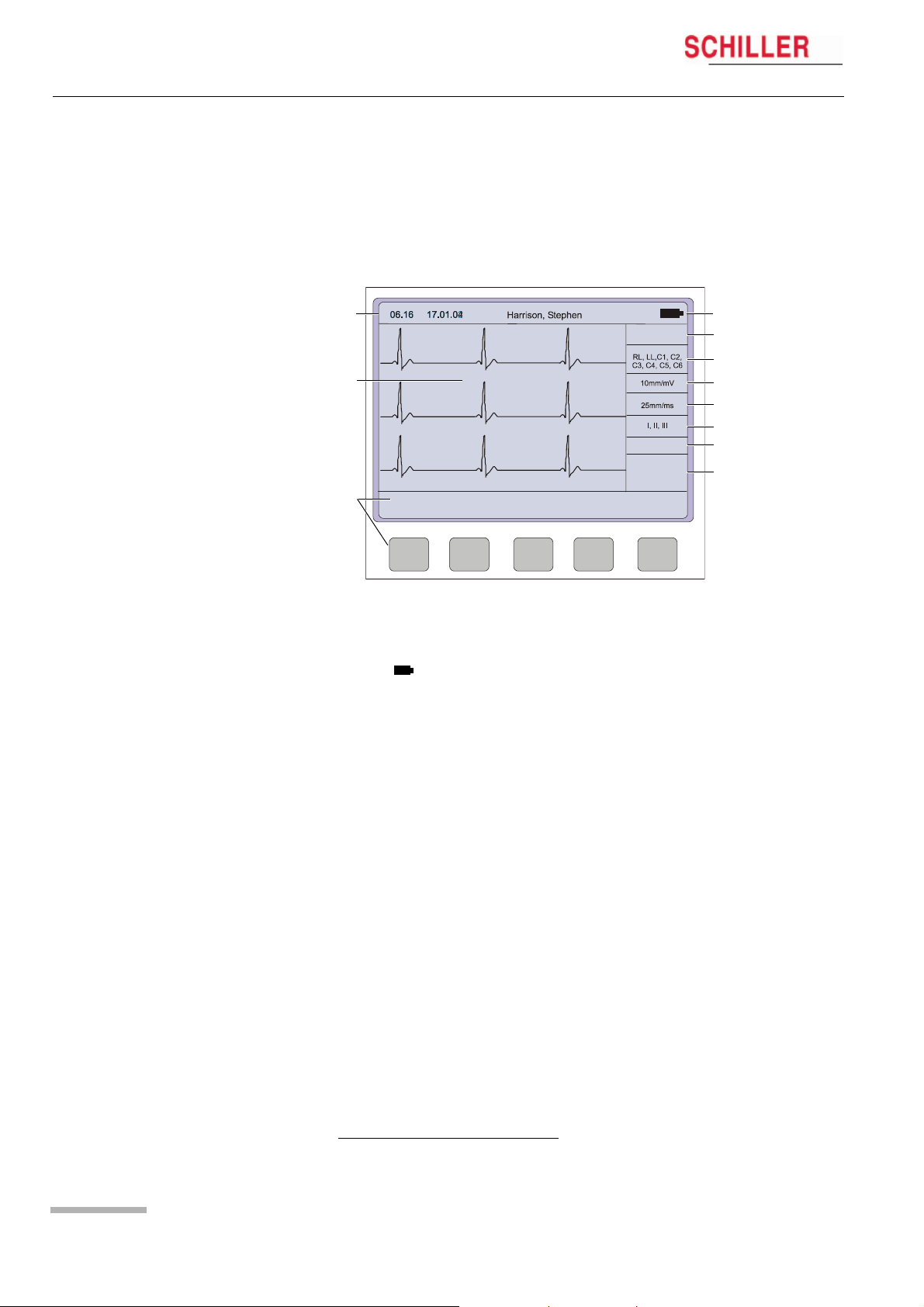
The display will vary according to the current task being carried out. In all screens
however, the top and bottom lines always display the same information: the top line
displays system information, and the bottom line always gives the softkey options.
The following is an example of a typical resting ECG screen.
1
HR:
78 / min
~
4
5
2
6
7
8
FILTER OFF
9
10
3
LEAD
TEST
MANUAL
MENU
Items 1, 2 and 3 are in the same position for all screens.
(1) Top line — time, date, patient name, and current power source — mains (~), or bat-
tery ( ). When battery capacity is limited the battery symbol flashes.
(2) Data acquisition area or data entry area.
(3) Softkey designation. Pressing the key below the text carries out the function in-
dicated. The options available will change according to the screen displayed.
Items 4 to 10 are specific for ECG acquisition only:
Page 14
(4) Current Heart Rate (averaged over 4 beats and refreshed every 2 seconds).
The HR is also given on a manual printout. Note that with an auto mode printout
the HR is averaged over the full 10 seconds of the recording.
(5) Electrode connections — when an electrode indication flashes (an audible alarm
is also given), it indicates that the electrode resistance is too high. The electrode(s) must be reapplied.
(6) Sensitivity 5, 10 or 20 mm/mV. Change the sensitivity with the keys 3 (auto), 4,
5 and 6. An ‘A‘ in this box indicates that automatic sensitivity is selected (auto
mode printout only).
(7) Speed 25 or 50 mm/s. Change the speed with the keys 8 and 9.
(8) Lead indication (leads currently displayed on the screen). Change the lead
group with the < and > keys on the keypad.
1
Myogram Filter indication — ‘Filter ON’ or ‘Filter OFF’. The filter is applied with
(9)
the filter key.
(10) Area for system messages or instructions.
1.The frequency of the filter cutoff is defined on page 37 menu Filters.
Art.-no.: 2.510526 Rev.: c
Operation 3
AT-101 User Guide Start-up and Initial Preparation 3.1
3Operation
3.1 Start-up and Initial Preparation
V Danger of electrical shock. Do not operate the unit if the earth connection is su-
spect or if the mains lead is damaged or suspected of being
damaged.
3.1.1 Connecting AT-101
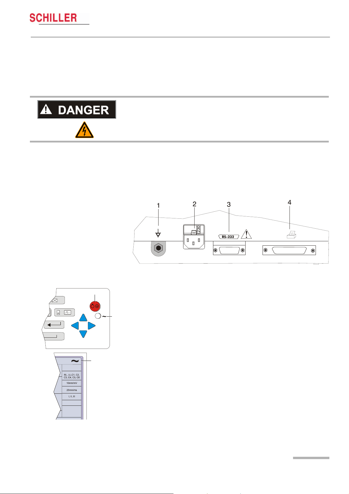
(1) Potential equalisation
(2) Mains connection (100 — 115 or 220 — 240 V)
(3) RS-232 (see safety note paragraph 1.6)
(4) Printer (see safety note paragraph 1.6)
Fig. 3.1 AT-101 back panel
1. Check Voltage setting (2) 115 or 230 V. Refer to chapter 6.4 for the mains voltage.
5
6
7
HR:
78 / min
Art.-no.: 2.510526 Rev.: c
FILTER OFF
2. Connect the power cable at the rear of the unit.
The mains indicator lamp (6) is always lit when the unit is connected to the mains
supply. If the unit is switched on, the relevant symbol is displayed on the LCD (7)
Leave the AT-101 connected to the mains for 7 hours to fully charge the battery.
3. Connect the potential equalisation cable and all other necessary cables at the
rear of the AT-101.
4. Press the on/off button (5). The patient data or the ECG acquisition screen is displayed (see paragraph 5.3.1.)
5. Check the settings according to chapters 5.
6. Connect the patient cable on the right side panel.
Page 15
3Operation
3.1 Start-up and Initial Preparation
3.1.2 Battery Operation
HR:
78 / min
FILTER OFF
1
AT-101
Important
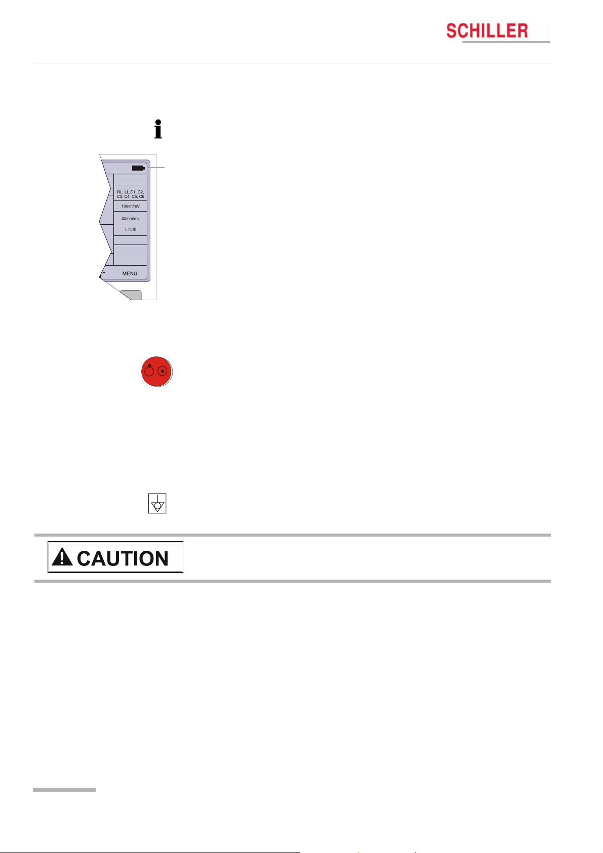
The unit can either be operated from the mains supply or from the built-in rechargeable battery. The power source is indicated on the top line of the LCD. The internal battery provides power for up to 3 hours.
• When the unit is running on battery power a battery symbol (1) is displayed.
• When working from battery power, the unit is automatically switched off after 5 minutes (30 seconds if battery capacity is limited) if no key is pressed.
• for Battery recharging refer to chapter 6.3.
• The unit can remain connected to the mains supply without damage to either the
battery or the unit.
3.1.3 Switching ON and OFF
« The AT-101 is switched ON and OFF with the ON/OFF key.
3.1.4 Isolating the Mains Supply
To isolate the power supply, remove the mains plug from the wall socket.
(see Fig. 3.1)
3.1.5 Potential Equalisation
The potential equalisation stud (see Fig. Fig. 3.1) at the rear of the unit can be used
to equalise the ground potential of the AT-101 to that of all mains powered equipment
in the vicinity. Use the hospital or building common ground
V To prevent the possibility of leakage current when an external printer is connec-
ted, always ensure that the mains lead, or the potential equalisation (next to the
mains connector), is attached to the AT-101
A yellow/green ground cable for connection to the potential equalisation stud is supplied as an option (Article number 2.310005).
Page 16
Art.-no.: 2.510526 Rev.: c
Operation 3
AT-101 User Guide Start-up and Initial Preparation 3.1
3.1.6 Inserting Printing Paper
Important
The device is delivered without printing paper installed. Only use original SCHILLER
printing paper. The thermo-paper is sensitive to heat, humidity and chemical vapours.
Store the paper in a cool and dry area.
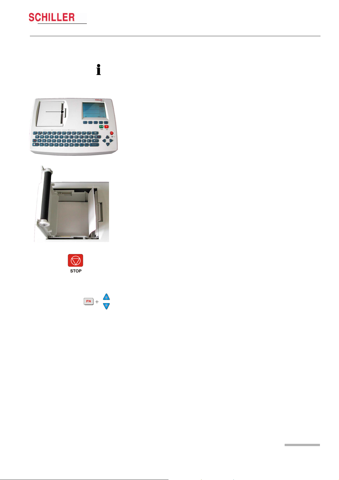
1. Press the locking catch (1) to the right.
1
2. Open the printer door upward.
3. Insert paper and pull it down.
4. Close the cover. Be sure that the paper lies exactly between the rails.
5. Press the STOP key to transport the paper to the start position.
3.1.7 LCD contrast adjustment
« Press the function key FN and the UP/DOWN arrows to adjust screen contrast.
Art.-no.: 2.510526 Rev.: c
Page 17
Loading…
Schiller AT 101 Service manual
- Addeddate
- 2020-05-20 09:06:06
- Classification
- Clinical;Cardiac Equipment;Electrocardiograph (ECG EKG);Welch Allyn Schiller ECG EKG;Schiller AT-101
- Identifier
- manual_Schiller_AT-101_-_Service_manual
- Identifier-ark
- ark:/13960/t8dg5hx17
- Ocr
- ABBYY FineReader 11.0 (Extended OCR)
- Page_number_confidence
- 98.46
- Ppi
- 300
- Scanner
- Internet Archive Python library 1.9.0
comment
Reviews
There are no reviews yet. Be the first one to
write a review.
216
Views
DOWNLOAD OPTIONS
Temporarily Unavailable
DAISY
For users with print-disabilities
Uploaded by
Sketch the Cow
on

|
AT-101/ Tele |
Эксплуатация |
3 |
|
Начальная подготовка |
3.1 |
|
3 Эксплуатация
3.1Начальная подготовка
VОпасность удара током. Не используйте прибор, если существуют сомнения относительно качества заземления или при повреждении или подозрении на повреждение сетевого шнура.
3.1.1Подсоединение AT-101
(1)Вывод заземления
(2)Сетевой разъем (100 — 115 или 220 — 240 В)
(3)RS-232 (см. раздел 1.6)
(4)Принтер (см. раздел 1.6)
(5)Сеть
(6)Модем
Кат. №: 2.510293 Версия: c
Рис. 3.1 Задняя панель AT-101
1.Проверьте установку напряжения (2) 115 или 230 В. Подробнее см. раздел
6.4.
|
5 |
2. |
Подсоедините сетевой шнур к задней панели прибора. |
|
|
Индикатор сетевого питания (6) будет гореть всегда, когда прибор |
|||
|
. |
подсоединен к сети. Когда прибор включен, соответствующий символ горит |
||
|
6 |
на экране (7). Оставьте АТ-101 подключенным к сети на 7 часов, чтобы |
||
|
батарея полностью зарядилась. |
|||
|
3. |
Подсоедините кабель заземления и все другие необходимые кабели к |
||
|
задней панели АТ-101. |
|||
|
4. |
Нажмите клавишу включения/выключения (5). Визуализируется экран |
||
|
~ |
данных пациента или экран регистрации ЭКГ (см. раздел 5.3.1.). |
||
|
7 |
5. |
Проверьте установки, как описано в Разделе 5. |
|
|
6. |
Подсоедините кабель пациента к разъему с правой стороны прибора. |
Страница 21
Представительство SCHILLER AG в странах СНГ Тел./факс (495) 956 29 10, 970 11 33; mail@schiller-ag.com; www.schiller-cis.com

|
3 |
Эксплуатация |
AT-101/ Tele |
|
3.1 |
Начальная подготовка |
|
3.1.2Работа от батареи
Важно
Прибор может работать как от сети, так и от встроенного аккумулятора. Источник питания указывается в верхней строке экрана. Встроенный
аккумулятор гарантирует до 3 часов работы.
1
•Когда прибор работает от аккумулятора, визуализируется символ батареи
(1).
•При работе от батареи прибор автоматически выключается через 5 минут (30 секунд, если емкость батареи ограничена), если не нажимается ни одна клавиша.
•См. раздел 6.3 по зарядке аккумулятора
•Прибор может оставаться подключенным к сети без риска повреждения батареи или прибора.
3.1.3Включение и выключение прибора
«АТ-101 включается и выключается при помощи клавиши ВКЛ/ВЫКЛ.
3.1.4Изоляция сетевого питания
Для изоляции источника питания выньте сетевой штекер из розетки. (см рис. 3.1)
3.1.5Заземление
Вывод заземления (см. Рис. 3.1) находится на задней панели прибора и используется, чтобы уравнять потенциал заземления АТ-101 с потенциалом заземления всех близлежащих приборов, работающих от сети. Используйте общее заземление больницы или здания.
VДля предотвращения возможной утечки тока при подсоединении внешнего принтера убедитесь, что сетевой кабель или кабель заземления подсоединен к AT-101
Дополнительно может быть поставлен желтый/зеленый кабель заземления
(кат. номер 2.310005).
Кат. №: 2.510293 Версия: c
Страница 22

|
AT-101/ Tele |
Эксплуатация |
3 |
|
Начальная подготовка |
3.1 |
|
3.1.6Заправка регистрирующей бумаги
Важно
Прибор поставляется без бумаги в лотке для бумаги. Используйте только оригинальную бумагу SCHILLER. Термобумага чувствительна к жаре, влажности и химическим веществам. Храните бумагу в прохладном и сухом месте.
1.Нажмите клавишу открытия лотка для бумаги (1).
2.Откройте крышку лотка для бумаги.
3.Вставьте бумагу.
4.Закройте крышку. Убедитесь, что бумага находится точно между направляющими.
5.Нажмите клавишу СТОП, чтобы передвинуть бумагу в требуемое положение.
STOP
Кат. №: 2.510293 Версия: c
Страница 23
Представительство SCHILLER AG в странах СНГ Тел./факс (495) 956 29 10, 970 11 33; mail@schiller-ag.com; www.schiller-cis.com

|
3 |
Эксплуатация |
AT-101/ Tele |
|
3.1 |
Начальная подготовка |
|
3.1.7Настройка контрастности экрана
« Удерживайте функциональную клавишу ФУНКЦ и при помощи стрелочек ВВЕРХ/ВНИЗ настройте контрастность экрана.
3.1.8Установка SIM карты на AT-101 Tele
|
Отвертка размер 0 |
|||
|
1. |
Нажмите клавишу выброса (1) при помощи отвертки. |
||
|
2 |
2. |
Вытяните держатель карты |
|
|
3. |
Вставьте SIM карту в держатель (2). |
||
|
1 |
4. |
Аккуратно задвиньте держатель карты в отделение для карты до щелчка. |
|
|
Примечание |
|||
|
Убедитесь, что держатель с SIM картой вставлен правильно и карта не выпадет. |
3.1.9Инсталляция антенны на AT-101 Tele
Гаечный ключ размер 8
VИспользуйте только антенны, протестированные и одобренные компанией
SCHILLER AG.
V Максимально допустимый коэффициент усиления антенны 8.4 dBi при
1900 МГц и 2.9 dBi при 850 МГц.
1.Перед монтажом антенны вставьте SIM карту.
2.Держите антенну под прямым углом к прибору и зафиксируйте ее гайкой при помощи гаечного ключа.
Внимание: не закручивайте гайку слишком сильно.
Кат. №: 2.510293 Версия: c
Страница 24

Кат. №: 2.510293 Версия: c
|
AT-101/ Tele |
Эксплуатация |
3 |
|
Ввод данных пациента |
3.2 |
|
3.2Ввод данных пациента
В этом экране возможен ввод нового пациента или изменение данных выбранного пациента.
« Нажмите клавишу данных пациента.
|
Фамилия |
: |
_ |
|
Имя |
: |
|
|
Пациент # |
: |
|
|
Год ржд. |
: |
(дд-мм-гггг) |
|
Возраст |
: |
|
|
Пол |
: |
|
|
Рост |
: |
см |
|
Вес |
: |
кг |
|
АД |
: |
ммРт.ст. |
|
Лекарства |
: |
|
|
МЕНЮ |
|
Фамилия |
Введите фамилию пациента (максимум 20 знаков) |
|
Имя |
Введите имя пациента (максимум 20 знаков). |
|
№ пациента |
Номер пациента — это короткая форма идентификации пациента — возможен |
|
ввод до 20 символов. |
|
|
Дата рождения |
Введите дату рождения как дд-мм-гггг. |
|
Возраст пациента рассчитывается по ближайшему году. |
|
|
Возраст |
Рассчитывается автоматически при вводе даты рождения. |
|
Пол |
Введите пол пациента «М» или «Ж». |
|
Рост |
Введите рост пациента в пределах от 20 до 250 см. |
|
Вес |
Введите вес пациента в пределах от 0.5 до 250 кг |
|
АД |
Введите систолическое (или диастолическое) давление пациента. |
|
Лекарства |
Возможен ввод до 23 символов для заметок о медикации. |
|
После ввода всех данных нажмите клавишу МЕНЮ для подтверждения. |
Страница 25
Представительство SCHILLER AG в странах СНГ Тел./факс (495) 956 29 10, 970 11 33; mail@schiller-ag.com; www.schiller-cis.com

|
4 |
ЭКГ покоя |
AT-101/ Tele |
|
4.1 |
Наложение электродов |
|
4 ЭКГ покоя
V Инструкции по наложению электродов на пациента приводятся исключительно как справочная информация. Они не заменяют решения специалиста.
4.1Наложение электродов
Цветокодировка, приведенная здесь, соответствует требованиям Кода 1 (Европейский). Цветовой эквивалент по коду 2 приведен в разделе 4.2.3.
Кат. №: 2.510293 Версия: c
Страница 26

|
AT-101/ Tele |
ЭКГ покоя |
4 |
|
Наложение электродов |
4.1 |
|
Для получения оптимального сигнала ЭКГ и обеспечения высокого качества регистрации необходимо, чтобы сопротивление между кожей и электродом было минимальным. Для этого следует соблюдать следующие требования:
1.Убедитесь, что в помещении тепло и пациент расслаблен.
2.Побрейте область наложения электрода до того, как очистить ее.
3.Очистите область наложения электрода спиртовым тампоном
4.Нанесите слой геля на кожу в месте наложения электрода.
5.Первым прикрепите электрод С4 в пятом межреберье по среднеключичной линии.
6.Затем расположите:
–C1 в четвертом межреберье по правому краю грудины
–C2 в четвертом межреберье по левому краю грудины
–C3 между С4 и С2 на равном расстоянии
–C6 по левой среднеподмышечной линии на уровне С4
–C5 между С4 и С6 на равном расстоянии
Сопротивление электродов можно проверить на экране регистрации — см. раздел 4.3.1.
При снятии ЭКГ у ребенка иногда чисто физически трудно наложить все электроды. В этом случае электрод С4 может быть наложен с правой части грудины.
VДля записи электрокардиограммы нужно убедиться в том, что ни пациент, ни токопроводящие части наложенных на него электродов (включая нейтральный электрод), не контактируют с другим человеком или другими токопроводящими предметами (даже если они заземлены).
Кат. №: 2.510293 Версия: c
Страница 27
Представительство SCHILLER AG в странах СНГ Тел./факс (495) 956 29 10, 970 11 33; mail@schiller-ag.com; www.schiller-cis.com
|
4 |
ЭКГ покоя |
AT-101/ Tele |
|
4.2 |
Дополнительные комбинации отведений |
|
4.2Дополнительные комбинации отведений
4.2.1Отведения по Небу
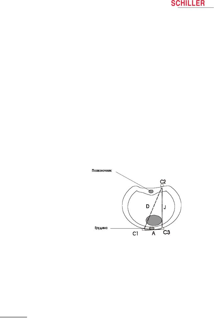
Отведения по Небу — это биполярные грудные отведения. Они представляют особенный интерес для диагностики изменений задней стенки желудочка. Три отведения организованы в форме «малого кардио-треугольника». Дорсальное (спинное) отведение по Небу (D) измеряется между электродами Nax и Nst; переднее отведение по Небу (А) — между Nap и Nst, а нижнее (J) между точками
Nap и Nax.
Наложите электроды следующим образом:
|
Цветовой код |
Идентификация |
Накладывается на участок: |
|
|
электрода |
|||
|
Красный |
C1 |
(Nst) |
2 ребро по правому краю грудины |
|
Желтый |
C2 |
(Nax) |
точно напротив 3 электрода (Nap) на |
|
спине |
|||
|
Зеленый |
C3 |
(Nap) |
5 межреберье по среднеключичной |
|
линии (сердечная ось) |
|||
Все остальные электроды могут быть наложены на их обычные позиции. Комбинация электродов, определенная пользователем, должна быть установлена в меню Настройки:
МЕНЮ > НАСТРОЙКА > УСТАНОВКИ ЭКГ > 4 х СЛЕДУЮЩИЙ > НЕБ (D, A, J) > ВКЛ.
См. раздел 5.2.5 для получения более подробной информации.
Кат. №: 2.510293 Версия: c
Страница 28

|
AT-101/ Tele |
ЭКГ покоя |
4 |
|
Дополнительные комбинации отведений |
4.2 |
|
4.2.2Наложение электродов для дополнительных отведений
Клипсы с грудных электродов С1 — С3 должны быть отсоединены и подсоединены к электродам С7 — С9, расположенным на спине пациента. Все остальные электроды могут быть наложены на обычные позиции.
Комбинация электродов, определенная пользователем, должна быть установлена в меню Настройки:
НАСТРОЙКА > УСТАНОВКИ ЭКГ > 4 х СЛЕДУЮЩИЙ > задние и прекардиальные опции. Выберите «вкл.» или «выкл.» для визуализации дополнительных отведений.
« В процессе получения данных выберите группу отведений при помощи клавиш групп отведений.
См. раздел 5.2.5 для получения подробной информации.
Дополнительные отведения С7 — С9 могут быть зарегистрированы только в ручном режиме.
Кат. №: 2.510293 Версия: c
Страница 29
Представительство SCHILLER AG в странах СНГ Тел./факс (495) 956 29 10, 970 11 33; mail@schiller-ag.com; www.schiller-cis.com

|
4 |
ЭКГ покоя |
AT-101/ Tele |
|
4.2 |
Дополнительные комбинации отведений |
|
4.2.3Идентификация и цветокодировка электродов и нейтрального электрода
Позиции наложения электродов, указанные в настоящем руководстве, помечены цветами в соответствии с требованиями Кода 1. Эквиваленты в
соответствии с Кодом 2 приводятся в следующей таблице.
|
Код 1 (обычно Европейский) |
Код 2 (обычно Американский) |
||||
|
Система |
Идентификация |
Цветокодировка |
Идентификация |
Цветокодировка |
|
|
R |
Красный |
RA |
Белый |
||
|
Конечность |
L |
Желтый |
LA |
Зеленый |
|
|
F |
Зеленый |
LL |
Красный |
||
|
C |
Белый |
V |
Коричневый |
||
|
C1 |
Белый / красный |
V1 |
Коричневый / красный |
||
|
Грудная клетка |
C2 |
Белый / желтый |
V2 |
Коричневый / желтый |
|
|
по |
C3 |
Белый / зеленый |
V3 |
Коричневый/ зеленый |
|
|
Вилсон |
C4 |
Белый / коричневый |
V4 |
Коричневый / голубой |
|
|
C5 |
Белый / черный |
V5 |
Коричневый/ оранжевый |
||
|
C6 |
Белый / фиолетовый |
V6 |
Коричневый / фиолетовый |
||
|
I |
Голубой / красный |
I |
Оранжевый / красный |
||
|
Позиции |
E |
Голубой / желтый |
E |
Оранжевый / желтый |
|
|
по |
C |
Голубой / зеленый |
C |
Оранжевый / зеленый |
|
|
Франку |
A |
Голубой / коричневый |
A |
Оранжевый / коричневый |
|
|
M |
Голубой / черный |
M |
Оранжевый / черный |
||
|
H |
Голубой/ фиолетовый |
H |
Оранжевый / фиолетовый |
||
|
F |
Зеленый |
F |
Зеленый |
||
|
Нейтральный |
N |
Черный |
RL |
Зеленый |
|
Кат. №: 2.510293 Версия: c
Страница 30
Schiller AT-101 Service handbook
- Schiller
- Medical Equipment
- Service handbook for Schiller AT-101
- schiller-at-101-service-handbook-66_manual.pdf
- 66 |
Pages Preview:
Document Transcription:
See Details
Download
Schiller AT-101 Medical Equipment PDF User Guides and Manuals for Free Download: Found (2) Manuals for Schiller AT-101 Device Model (Operation & User’s Manual, Service Handbook)
The Schiller AT-101 is a remarkable addition to the lineup of medical equipment designed to enhance patient care and streamline workflows in healthcare settings. This device stands out for its versatility and efficiency, making it an essential tool for professionals who demand reliability during critical medical assessments. With its advanced features and user-friendly design, the AT-101 has quickly made a name for itself in hospitals and clinics alike.
One of the key aspects of the Schiller AT-101 is its innovative technology that facilitates accurate monitoring. Healthcare providers can utilize the AT-101 to perform a range of vital sign assessments, ensuring that all necessary data is gathered swiftly and accurately. This is particularly important in emergency situations where every second counts. The AT-101 is equipped with high-precision sensors that provide real-time feedback, allowing medical personnel to make informed decisions rapidly.
Ease of use is another factor that sets the Schiller AT-101 apart. The device features a straightforward interface that enables quick navigation through various functionalities. Here are some key highlights regarding its user interface:
- Intuitive Design: The layout is clean and easy to navigate, which helps reduce training time for new users.
- Display: A clear, bright display allows healthcare personnel to read measurements without straining, even in low-light conditions.
- Customizable Settings: Users can easily adjust settings based on the specific needs of different patients or departments.
Moreover, the Schiller AT-101 is designed with portability in mind. Its compact design allows it to be easily transported within a healthcare facility, ensuring that it can be accessed whenever and wherever needed. This flexibility is essential for emergency room staff and first responders who require mobility without compromising on the quality of care.
Another significant advantage of the AT-101 is its connectivity features. The device can seamlessly integrate with existing hospital information systems, ensuring that patient data is securely transmitted and stored. This capability not only enhances the workflow but also minimizes the risks of data breaches, keeping sensitive information safe.
In terms of performance, the Schiller AT-101 offers exceptional reliability. Its robust construction makes it suitable for frequent use in various medical environments. Users have reported consistent performance, which is crucial for maintaining operational standards in busy clinics and emergency rooms. The AT-101’s longevity is an added benefit, as it translates to less frequent replacements, thereby reducing overall costs for healthcare institutions.
While the Schiller AT-101 brings many advantageous features, it is also essential to consider user feedback. Many healthcare professionals have praised its functionality and ease of use, but some have mentioned that additional training materials could further enhance the onboarding experience. Continuous improvement in training resources could significantly benefit new users as they familiarize themselves with this sophisticated device.
In conclusion, the Schiller AT-101 proves to be an invaluable asset in the medical field, combining accuracy, ease of use, and portability all in one device. This product meets the demands of modern healthcare, making it a top contender for any facility looking to upgrade their monitoring equipment. With its blend of innovative technology and practical design, the AT-101 will likely continue to gain traction among healthcare providers who value high-quality, efficient tools for patient care.