
SES2000
A UT O CLAVE
Service Manual
699215
ST-SM8l
Introduction
Description
Maintenance
Illustrated parts list
Read these Instructions before use
Keep these instructions in a safe convenient place for future reference. Read in conjunction
with the Publications detailed in Section 1.5.
This Service Manual applies to the following Autoclave REF numbers. (Note: In the parts list
section reference is also made to parts required for earlier versions) :-
SES 2000 STANDARD (from Serial Number — SCB8B0000, or SED8B0000 for non-CE)
without printer : 87-028-04 87-028-20 87-028-36 87-029-05 87-029-13 87-029-21
87-029-37 87-029-45 87-029-54 87-029-62 87-029-70 87-029-78
87-029-86 87-030-03 87-030-11 87-030-27 87-030-43 87-030-60
87-031-03 87-031-68
with printer : 87-028-12 87-028-28 87-028-44 87-029-26 87-030-65 87-031-11
87-031-76
SES 2000 LONG (from Serial Number — LSCB8B0000, or LSED8B0000 for non-CE)
without printer : 87-028-53 87-028-69 87-028-85 87-028-90 87-028-97 87-029-29
87-029-94 87-030-70 87-031-19 87-031-84 87-020-05 87-022-01
87-022-17 87-020-21 87-022-49 87-022-66
with printer : 87-028-61 87-028-77 87-030-75 87-031-27 87-031-92 87-020-13
87-022-09 87-022-25 87-020-29 87-022-58 87-022-74
(Note: The alpha parts of the SN are significant.)
Eschmann After Sales Service Department
The Eschmann After Sales Service Department is staffed and equipped to provide advice and
assistance during normal office hours. To avoid delays when making enquires, please quote the
Model and Serial Number of your Autoclave. Please ensure you include all alpha and numeric
digits of the Serial Number. (NOTE: The Serial Number Plate is located inside the door in the top
left hand corner).
For further information visit www.eschmann.co.uk
All correspondence relating to the after sales service of Eschmann Equipment to be addressed to :
UK Customers
Eschmann Equipment, Peter Road, Lancing, West Sussex BN15 8TJ, England.
Tel: +44 (0) 1903 765040. Fax: +44 (0) 1903 875711.
Overseas Customers
Contact your local distributor. In case of doubt contact Eschmann Equipment.
Patents and Trade marks
The ESCHMANN name and logo are trade marks of Eschmann Holdings Limited.
“Eschmann Equipment” is a trading name of Eschmann Holdings Limited.
“SES2000” is a trade mark of Eschmann Holdings Limited.
Patents : Patents Pending plus — Pat. US5090033 and Pat. GB2238407
Copyright © 2008 Eschmann Holdings Limited
All rights reserved. This booklet is protected by copyright. No part of it may be reproduced, stored in a
retrieval system or transmitted in any form or by any means, electronic, mechanical, photocopying,
recording or otherwise without written permission from Eschmann Holdings Limited.
The information in this publication was correct at the time of going to print. The Company, however,
reserves the right to modify or improve the equipment referred to.
Service Manual
ST-SM8l November 2008
The CE marking affixed to the product certifies that it complies with the
European Medical Devices Directive 93/42/EEC and related legislation.

SES 2000 AUTOCLAVE
CONTENTS
Page
Contents .. .. .. .. .. .. .. .. 3
Technical data .. .. .. .. .. .. .. 4
PART 1 INTRODUCTION
General .. .. .. .. .. .. .. .. 6
Associated publication .. .. .. .. .. 6
Servicing .. .. .. .. .. .. .. .. 6
PART 2 DESCRIPTION
General .. .. .. .. .. .. .. .. 7
Operating features .. .. .. .. .. .. 7
Operation cycle .. .. .. .. .. .. 9
Operation .. .. .. .. .. .. .. 9
Display messages .. .. .. .. .. .. 10
Error indication .. .. .. .. .. .. 11
General .. .. .. .. .. .. .. 11
Overheating .. .. .. .. .. .. 11
PART 3 MAINTENANCE
Fuses .. .. .. .. .. .. .. .. 15
Fault diagnosis and table .. .. .. .. 15
Parts replacement and adjustment .. .. 20
Removing cover .. .. .. .. .. .. 20
Refitting cover .. .. .. .. .. .. 20
Thermal fuse .. .. .. .. .. .. 20
Transformer.. .. .. .. .. .. .. 20
Controller board .. .. .. .. .. .. 20
Pressure door lock .. .. .. .. .. 20
Air valve .. .. .. .. .. .. .. 21
Door interlock switch .. .. .. .. .. 21
Solenoid door lock (CE only) .. .. .. 22
Heater cycling thermostat .. .. .. .. 22
Temperature sensors .. .. .. .. .. 22
Fill and Discharge valves .. .. .. .. 22
Solid state relay (Non-CE) .. .. .. 22
Solid state relay (CE only) .. .. .. 23
Mechanical relay (CE only) .. .. .. 23
Heating element .. .. .. .. .. .. 23
Printer interface board .. .. .. .. 23
Voltage regulators .. .. .. .. .. 23
Door seal .. .. .. .. .. .. .. 23
Pressure gauge .. .. .. .. .. .. 23
Discharge line filter .. .. .. .. .. 24
Printer .. .. .. .. .. .. .. 24
Special operating modes .. .. .. .. 24
Demonstration mode .. .. .. .. .. 24
Engineering mode .. .. .. .. .. 24
Set-up mode .. .. .. .. .. .. 25
Switch identities and function .. .. .. 25
Power-on modes .. .. .. .. .. 25
Page
Set-up procedure .. .. .. .. .. 26
Autoclave without printer .. .. .. 26
Autoclave with printer .. .. .. .. 26
Setting the Autoclave Serial Number 26
Entering the Autoclave Serial Number 27
Entering the date and time.. .. .. 27
Errors and error clearing .. .. .. .. 28
General .. .. .. .. .. .. .. 28
Control sensor selection .. .. .. .. 28
Autocheck .. .. .. .. .. .. .. 28
Routine Autoclave Calibration .. .. .. 28
General .. .. .. .. .. .. .. 28
Calibration procedure .. .. .. .. 29
Safety valve .. .. .. .. .. .. .. 29
Operational test .. .. .. .. .. .. 30
PART 4 ILLUSTRATED PARTS LISTS
Pipes and fittings, latest models .. .. .. 30
Illustrated parts list 1: Pipes and valves .. 31
Illustrated parts list 2: General spares .. 33
Illustrated parts list 3:
Heater and process controls .. .. .. .. 35
ILLUSTRATIONS
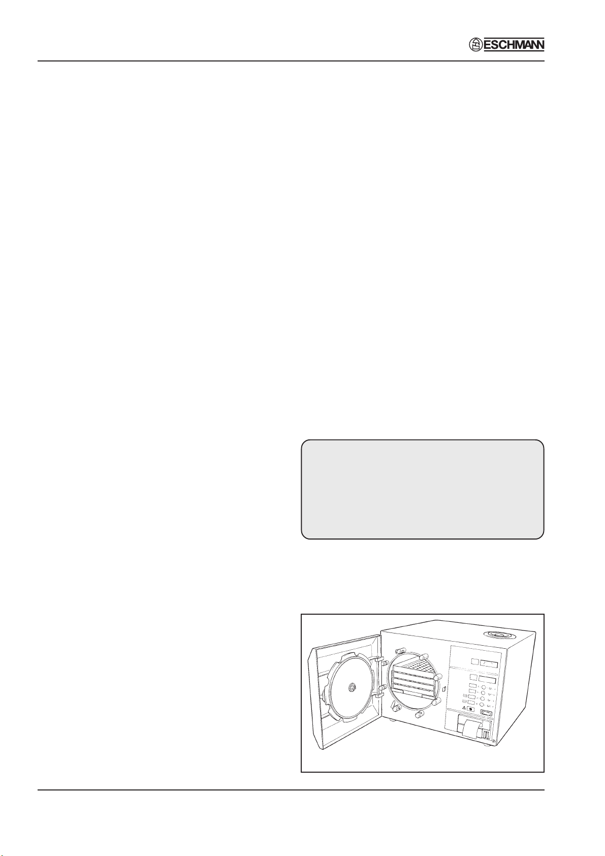
Fig. 1 SES 2000 Autoclave .. .. .. .. 6
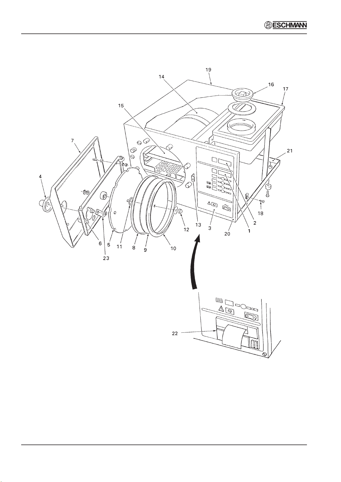
Fig. 2 Autoclave General Arrangement .. 12
Fig. 3 Autoclave: Pipes and Valves .. .. 13
Fig. 4 Autoclave: Heater & Process Controls 14
Fig. 5 Door interlock microswitch .. .. 21
Fig. 6 Filter unit disassembly .. .. .. 24
Fig. 7 Switch identities and function .. .. 25
Fig. 8 Autoclave Controller boards .. .. 30
Fig. 9 Pipes and valves .. .. .. .. 32
Fig. 10 General spares .. .. .. .. .. 34
Fig. 11 Heater and process controls .. .. 36
Fig. A1-A5 Autoclave printer details .. .. 40
TABLE
Fault Diagnosis table .. .. .. .. .. 15
APPENDIX A
Autoclave printer .. .. .. .. .. .. 39
APPENDIX B
Schematic — Pipes and Valves .. .. .. 41
APPENDIX C
Schematic — Wiring .. .. .. .. .. 42
ST-SM8l Page 3 of 43

SES 2000 AUTOCLAVE
TECHNICAL DATA
(Standard Version)
Electrical Data
Supply 220/230/240V a.c. at 50/60Hz
110V a.c. at 50/60Hz
Nominal Loading @ 230V — 2kW (8.7A)
@ 110V — 1.4kW (12.7A)
Fuses Chassis
230/240V 10A, Part No.380003, (x2)
400mA, Part No.696181, (x1)
220V 13A, Part No.380002, (x2)
400mA, Part No.696181, (x1)
110V 16A, Part No.111940, (x2)
800mA, Part No.380004, (x1)
Relay board
T2A, 250V (x1)
Safety standards
IEC 1010-1:1990
IEC 601-1:1977
BS5724:Part 1:1979
ESCHLE (Second Edition 1986)
IEC 601-1-2 (1993)
Dimensions
Autoclave Width 460mm
Length 461mm
Height 360mm
Chamber Diameter 200mm
Length 348mm (max)
Capacity 10.6 litres
Trays Width 183mm
Length 282.6mm
Height l7mm
Tray Loading 1.5 kg per tray
Weight (approx.)
Net 27.5kg
Shipping 32.0kg
Symbols
For use with alternating current
Caution Hot Surface
Sterilizing Data
Sterilizing time
At 134/137°C 3 mins 20 sec.
At 121/124°C 15 mins
Typical overall cycle 134°C : 13 minutes
time (D indicates 134°C : 30 minutes (D)
drying included) 121°C : 24 minutes
121°C : 41 minutes (D)
Note: Overall cycle times may vary depending
on machine and loading conditions.
Nominal Operating pressures:
134°C cycle — 3.14 bar abs
121°C cycle — 2.11 bar abs
Water reservoir
capacity 2.0 litres
Caution refer to accompanying
documents
Sterilising cycle without drying phase
(NB. temperature = cycle temperature)
Sterilising cycle with drying phase
(NB. temperature = cycle temperature)
Page 4 of 43 ST-SM8l

SES 2000 AUTOCLAVE
TECHNICAL DATA
(Long Version)
Electrical Data
Supply 230Vac at 50/60Hz
Nominal Loading @ 230V — 2.75kW (12A)
Fuses Chassis
15A, 250V, (x2) Part No. 301871
400mA, Part No. 696181
Relay board
T2A, 250V (x1)
Safety standards
IEC1010-1 (1990)
IEC 601-1-2 (1993)
Sterilizing Data
Sterilizing time
At 134/137°C 3 mins 20 sec.
At 121/124°C 15 mins
Typical overall cycle 134°C : 13 minutes
time (D indicates 134°C : 30 minutes (D)
drying included) 121°C : 24 minutes
121°C : 41 minutes (D)
Note: Overall cycle times may vary depending
on machine and loading conditions.
Dimensions
Autoclave Width 460mm
Length 650mm*
Height 360mm
* Feet spaced to fit 600mm worktop
Chamber Diameter 200mm
Length 500mm (max)
Capacity 15.6 litres
Trays Width 180mm
Length 457mm
Height 24mm
Tray Loading 3.0 kg per tray
Weight (approx.)
Net 35.5kg
Shipping 40kg
Symbols
For use with alternating current
Caution Hot Surface
Caution refer to accompanying
documents
Nominal Operating pressures:
134°C cycle — 3.14 bar abs
121°C cycle — 2.11 bar abs
Water reservoir
capacity 2.0 litres
Sterilising cycle without drying phase
(NB. temperature = cycle temperature)
Sterilising cycle with drying phase
(NB. temperature = cycle temperature)
ST-SM8l Page 5 of 43
Part 1
SES 2000 AUTOCLAVE
PART 1 INTRODUCTION
GENERAL (Fig. 1)
1.1 This Manual contains descriptive,
maintenance and spare parts information for the
SES 2000 Autoclave.
1.2 The autoclave is a portable, electrically
operated steam unit designed for sterilizing
unwrapped instruments, utensils and other items.
It operates automatically at the touch of a single
programme selector touch button, and has four
programmes 134°C and 121°C, both with and
without drying.
1.3 The autoclave is available with short or long
chambers and with or without an integral printer
for recording details of the sterilizing cycle. Details
of the printer are given in Appendix A.
1.4 Some of the information in this manual refers
to models built to comply with the Medical Devices
Directive and carry the CE mark to indicate
compliance. Where the section of this manual refers
only to these models it is marked ‘CE ONLY’
ASSOCIATED PUBLICATION
1.5 Separate installation and user instructions
are given in the SES 2000 Autoclave Instructions
for Use, ST-IM30.
SERVICING
1.6 Ensure that routine servicing is carried out
at regular intervals by either Eschmann trained
personnel or suitably trained engineers only,
otherwise the warranty could be infringed.
1.7 Keep the Instructions for Use and this Service
Manual readily accessible for reference purposes
prior to and during operation, cleaning and
servicing of the autoclave.
If ‘Sterile Water for Irrigation’ is not being used then
Eschmann strongly recommend the use of either
distilled water, deionized water, purified water or
water treated by the reverse osmosis process.
These types of water are low in dissolved solids
and can help reduce the effects of tap water
detailed below.
DO NOT USE TAP WATER, this is high in dissolved
solids and can deposit lime scale, block filters and
cause damage to the pressure vessel.
Eschmann also recommend that the reservoir is
drained, allowed to dry and is refilled on a weekly
basis, with the type of water detailed in ‘a’ (or ‘b’)
above. At every service interval the reservoir must
be removed, be thoroughly cleaned and dried,
and then refilled. This will reduce the build-up of
contaminants in the water that may cause blocked
filters and/or damage to the pressure vessel. Your
local Health Authority may suggest that you change
the reservoir water more frequently. Eschmann
advise you to follow your local Health Authority’s
recommendations.
1.9 Check the drain tap is not damaged or leaking
and return the tube and drain tap into its location
under the autoclave to prevent damage or
accidental opening.
IMPORTANT NOTE
If the drain tap is found to be damaged or
leaking, replace it as soon as possible (order
Part No. 380010 directly from Eschmann).
When fitting the new tap, drain the reservoir
first and ensure it is placed on the drain tube
correctly, see Fig. 3.
CAUTION
In common with other systems containing
static water reservoirs, water used in this unit
can become contaminated over a period of
time, or following an aborted cycle, and should
be treated as a potential risk of infection.
1.8 Eschmann recommend filling the reservoir
with ‘Sterile Water for Irrigation’. This is low in
dissolved solids and has a low microbial count. In
the U.K. the Department of Health recommend that
‘Sterile Water for Irrigation’ is used in bench-top
Autoclaves (NHS Estates document HTM2031).
Page 6 of 43 ST-SM8l
Fig. 1 SES 2000 Autoclave

SES 2000 AUTOCLAVE Part 2
PART 2 DESCRIPTION
GENERAL (Fig 2)
2.1 The autoclave is a portable steam unit heated by
a single element and can be supplied to suit any of the
mains supplies shown in Technical Data.
2.2 The unit is electronically controlled and offers a
selection of sterilizing programmes as follows:
134°C without the drying phase
121°C without the drying phase
134°C with the drying phase
121°C with the drying phase
For sterilizing pressures and drying times refer to
Technical Data.
2.3 The required sterilizing programme is selected
and started by pressing the appropriate programme
button on the front panel of the unit, following which the
sterilizing/drying cycle proceeds automatically until
complete. If the autoclave has a printer, the printer will
start automatically when the programme button is
pressed.
2.4 Indication of cycle status is provided by a digital
display. If an error should occur during a cycle this also
is indicated by the digital display.
OPERATING FEATURES (Figs 2, 3 and 4)
2.5 The following equipment, designed for control
and/or protection, is incorporated in the autoclave:
Pressure Gauge (Fig. 3 item 3). This is used to
indicate pressure inside chamber.
Process Display Window (Fig. 2 item 1). The
digital display indicates the temperature inside
the chamber and also provides simple messages
for the user which indicate the stages through the
cycle, and also error conditions, should any occur.
Four Programme Selector Buttons (Fig. 4, item
15). These are used to select and start a particular
cycle. They can also be used to place the machine
in the ‘Demonstration’ or ‘Engineering’ mode as
described later.
Green Light Emitting Diodes (LED’s) (Fig. 4 item
16). There are four LED’s and these are used
primarily to indicate the point at which the required
sterilizing cycle can be selected and started and,
when this has been done, to indicate which
particular cycle is in progress.
Power On/Off Switch (Fig. 4 item 17). This switch
controls mains power supply to the unit.
Overheat Warning Lamp (Fig. 4 item 18). The
illumination of this warning lamp indicates that the
protective thermal fuse (Fig. 4 item 7) has operated.
Door Latching Handle (Fig. 2 item 4). This handle
operates the door mechanism to secure the door
in the locked position against the chamber mouth.
Door Secondary Latch (Fig. 2 item 6). This engages
a safety catch to ensure the door does not fly open
should there be residual pressure in the chamber
when the door latching handle is operated. It is
also used to keep the door slightly open during the
drying part of the cycle.
Door Interlock Microswitch (Fig. 4 item 6). This is
used to signal to the controller that the door is
properly closed. It is operated via a simple
adjustable mechanism and should operate just as
the door becomes fully closed.
Pressure Door Lock (Fig. 3 item 7). This is a safety
device designed to ensure that the door cannot be
opened if the internal chamber pressure exceeds
2
approximately 0.2 bar (3.0 lbf/in
). The device
comprises a spring-loaded plunger driven by the
chamber pressure via a rubber diaphragm.
Solenoid Door Lock (Fig. 4 item 22) ‘CE ONLY’
see note page 38. This lock prevents the door
being opened by the operator, once the cycle has
been started. The lock holds the door closed until
the sterilizing cycle is complete. It will also keep
the door closed under all fault conditions. As
absence of power to the unit constitutes a ‘fault’
this also means that the unit power switch must be
switched ‘on’ in order to open the door.
Note: If it is necessary to override the electrical door
lock to clear an error code, this is done by switching off
the power switch then, after a few seconds, switching
it back on again while pressing and holding any one of
the programme selector buttons on the front panel.
Water Reservoir (Fig. 2 item 17). This is used to
hold distilled, deionized, or purified water before
being admitted to the chamber via the water fill
valve, and to receive the hot water and steam
vapour emitted from the chamber towards the end
of the cycle, via the discharge valve.
Heating Element (Fig. 4 item 1). This consists of
a single immersion element inside the chamber. It
is controlled via the solid state relay and heater
thermostat. Refer to the Technical Data for heater
element loading.
Solid State Relay (Fig. 4 item  ‘Non-CE Units’ see
note page 38. This is switched on and off by the
controller as necessary and is the means of controlling
the heater output. The solid state relay is fitted on the
protection relay printed circuit board which is mounted
on the internal bulkhead and is rated at 25A, 400V
(repetitive reverse blocking voltage) or such as to be
suitable for use on a 230V a.c. supply.
Solid State Relay (Fig. 4 item 8A) ‘CE ONLY’ see
note page 38. On CE units the Solid state relay is
fitted on the relay protection board.
Mechanical Relay (Fig 4 item 21) ‘CE ONLY’ see
note page 38. This relay isolates the heater circuit
ST-SM8l Page 7 of 43

Part 2 SES 2000 AUTOCLAVE
PART 2 DESCRIPTION
from the electrical supply prior to cycle start, and
following cycle completion, to give additional
protection.
Heater Cycling Thermostat (Fig. 4 items 2 and 3).
This is connected in series with the solid state
relay to the heating element. It is operated by a
fluid-filled capsule clamped to the heating element
which will cause the thermostat cut-out device to
operate if the heater surface temperature exceeds
a preset limit, safeguarding the autoclave. The
cut-out is self-resetting and will remake when the
temperature drops. Note that operation of the
thermostat cut-out during the drying phase of the
cycle is quite normal.
Thermal Fuse (Fig. 4 item 7). This is connected so
as to remove power from the heater if a serious
overheating condition should occur. Note however
that operation of this device is unlikely to occur
since the heating element is already protected by
the heater cycling thermostat.
Fuses (Fig. 4 items 9 and 10). The unit has four
fuses as follows:
Three fuses on the rear panel of the cabinet,
rated as shown under Technical Data. The
two larger fuses are connected into the ‘mains’
supply to the unit. The smaller fuse protects
the primary circuit of the transformer.
A fourth fuse, on the printed circuit board and
rated at 2A, protects the secondary circuit of
the transformer and other parts of the
controller.
Note: Units with a printer have an extra fuse which
is fitted on the printer PCB.
Transformer (Fig. 4 item 11). This converts the
incoming mains voltage to 20V a.c. to operate the
controller and the water fill and discharge valves.
A non-resetting thermal fuse is fitted in the
transformer secondary; check for secondary
‘continuity’ when fitting a replacement transformer.
Water Fill Valve (Fig. 3 item 1). This valve is used
to control the water fill sequence. It is electrically
operated from a 24V d.c. supply which is generated
and signalled from the controller.
Discharge Valve (Fig. 3 item 2). This valve is used
principally at the end of the sterilizing cycle to
allow water and steam vapour from the chamber
to pass back into the reservoir. It is also operated
at other times during the cycle. The valve is
electrically operated from a 24V d.c. supply
generated on the controller board.
Printer Interface Board (Fig. 4 item 20). This
board is fitted in autoclaves which have a printer.
The board interfaces the printer with the integrated
microprocessor-based control board.
Air Valve (Fig. 3 item 6). At the start of a cycle the
chamber is full of air, and for a satisfactory result
almost all of this has to be removed. This is done
by a small air valve. This valve contains a ball and
spring which allows air displaced by the steam
generated in the chamber to pass out into the
reservoir. Once steam starts to pass the ball, the
ball then lifts and seals. A small ‘bleed’ remains,
however, and it is quite normal for small quantities
of steam to escape into the reservoir throughout
the cycle.
Safety Valve (Fig. 3 item 5). This is fitted on the
manifold at the rear of the chamber, and is factory
set to release excess pressure from within the
chamber. It is a primary safety device and should
not be readjusted.
Temperature Sensor (Fig. 4 item 4). This is used
to sense the chamber temperature and is fitted on
the manifold in a position where the manifold is
exposed to a small volume of steam bled through
the air valve. This device with its associated leads,
mounting plate and connector, together form a
single assembly. The sensor controls the
temperature within the chamber and also the
display temperature.
Thermocouple Entry Port (Fig. 4 item 19). This
can be used to insert a thermocouple into the
chamber ‘drain line’ to allow the operating
temperature to be measured and adjusted if
necessary.
Water Drain Pipe (Fig. 3 items 8 and 9). This
provides a means of emptying the reservoir for
cleaning or for transportation.
PCB Controller Board (Fig. 4 item 12). The
autoclave has an integrated microprocessorbased controller. The controller handles every
aspect of management of the machine which
includes operation and control of the digital display,
the light emitting diodes and response to the
programme selection push buttons. The controller
receives information from the temperature sensor
and from the door interlock switch and is able to
detect a number of errors, and the times relative
to the cycle run when these occur. In addition to
controlling the sterilizer in the user mode, the
controller also supports a ‘demonstration’ and an
‘engineering’ mode (see Special Operating
Modes). The controller operates the heater via the
solid state relay and also controls the operation of
the water fill and discharge valves. A detailed
knowledge of the operation of the controller is not
necessary in order to service the autoclave; it is a
replaceable sub-assembly and should only be
changed as a last resort.
Page 8 of 43 ST-SM8l

SES 2000 AUTOCLAVE Part 2
PART 2 DESCRIPTION
Integral Printer (Fig. 2 item 22). If the autoclave
has a printer, it will start automatically when the
programme button is pressed and will print out a
hard copy of the sterilization cycle. Details of the
printer are given in Appendix A to this Manual.
OPERATION CYCLE
2.6 A detailed knowledge of the operation of the
autoclave is not necessary to be able to repair it
effectively; however, a basic understanding of the
various processes of the unit operation which occur
during a cycle is given in the following paragraphs.
Operation
CAUTION
Ensure that the reservoir is filled with water before
switching-on.
Note: When filling the reservoir, water treated by
reverse osmosis can be used as an alternative to
distilled, or deionized water.
2.7 Power to the unit is switched on by selecting the
power switch (0-I) to I. If the chamber door is open there
now follows a single high-pitched audible signal
accompanied by the display ‘SES’, followed by the
number of cycles, and finally ‘ready’ (or time of day if
printer fitted) in the display window.
2.8 If the door is closed, when power is switched on,
the display will alternate between ‘test’ and ‘door’. In
order to continue with the cycle the door must be opened,
at which point the display will change to ‘ready’ (or time)
and the four green indicators will come on.
2.9 After the work trays have been put in the chamber
and the door closed, a programme can be selected and
initiated by pressing one of the programme selector
buttons. If the autoclave has a printer it will automatically
start when the programme selector button is pressed.
2.10 When the door is closed, with power switched
on, this is sensed by the controller via the door interlock
switch. If any attempt is made to open the door once the
cycle has begun, the display ERR2 will appear, and an
audible signal will sound. Under these circumstances
it is necessary to switch the autoclave off and clear the
error as detailed in section 3.41.
2.11 On selecting the programme, ‘FiLL’ will be
displayed, indicating that the cycle has begun. Once
the chamber has filled with water from the reservoir, the
display will change to ‘HEAt’.
2.12 If all conditions are satisfactory, the controller will
set-up the operating parameters for the cycle selected,
and will switch on the heater.
2.13 The heater is controlled by a system which
ensures that the operating temperature is reached with
minimal overshoot. Initially the heater will be ‘on’
continuously and the measured temperature will be
displayed. Note, however, that the system does not
register temperatures below 92°C; hence the symbol
‘HEAt’ will appear and remain on display until a
temperature of 92°C is reached.
2.14 Temperatures are displayed and measured to
0.1°C. In addition, the controller uses signal averaging
to ensure a stable, accurate display.
2.15 Control of the cycle is now fully automatic with
temperature information being collected via the
temperature sensor. Timing is controlled by the controller
and cycle times cannot be adjusted. By comparing
measured values with known time/temperature
relationships, the controller is able to detect faults and
display them as error codes, this is accompanied by an
audible warning signal.
Note: Pressing the bottom 121°C button will display
the cycle counter.
2.16 To ensure efficient sterilization, the autoclave
operates at temperatures slightly above the minimum
recommended. Hence, the operating temperature for
the 121°C cycle is set to 122.5°C, and the 134°C cycle
is set to 135.5°C.
2.17 As the cycle enters the sterilizing phase the
display shows an ‘S’ (flashing) as a prefix to the
displayed temperature. At the end of the sterilizing
phase the heater is turned off and the discharge valve
is opened. At this point, a certain amount of noise from
the reservoir is quite normal.
2.18 Once the controller detects that chamber
temperature has fallen to a safe level, the flashing
display ‘End’ appears and an audible signal sounds to
indicate that the cycle is complete. When the chamber
door is opened the display will show ‘ready’.
Note: If the autoclave has a printer, the printout will
include the following details:
Manufacturer’s name
Autoclave type and serial number
Sterilization cycle type e.g.. 134°C without drying
Date and time for the start of sterilization cycle
Counter indication (five digits with leading zeros)
Sterilization cycle time and temperature
information
Sterilization cycle ended message
Time and date for the end of the sterilization cycle
Operating information relating to the printer is given in
Appendix A to this Manual.
ST-SM8l Page 9 of 43

Part 2 SES 2000 AUTOCLAVE
PART 2 DESCRIPTION
2.19 The overall time for the cycle is not fixed and
depends on many factors such as the supply voltage,
the load and the ambient temperature. However, the
controller will ensure a satisfactory sterilization cycle
even when these factors vary over wide ranges.
2.20 If a cycle employing a drying phase is selected,
operation to the end of the sterilizing phase is as
described above. After discharge of steam and water
back into the reservoir, however, the display ‘dry’
appears accompanied by a rapid intermittent audible
signal over a two second period to indicate the beginning
of the drying phase. At this point the operator should
first open the chamber door then push it towards the
closed position again until it just rests lightly against the
door safety catch. This leaves a sufficient gap to allow
vapour to escape.
2.21 The drying phase is about 17 minutes long
during which the heater is operated at low power.
Operation of the heater thermostat is quite normal
during this period. At the end of the drying phase the
display ‘End’ will appear for approximately 10 seconds
followed by ‘ready’, assuming that the door has been
opened as described in section 2. 20.
DISPLAY MESSAGES
2.22 Throughout a given cycle the following symbols
may appear as a digital display:
Display Meaning
ERR 2 Door opened after cycle has been
started
door/test Test door interlock switch (see
section 2. 23)
door, then Chamber door open and a cycle
cycle counter, button has been pressed (audible
then ready beep given)
Time of day Programme can now be selected
or ‘rEAdY’ (printer version shows ‘Time’, non-
printer version shows ‘rEAdY’)
FiLL Chamber being filled
HEAt Chamber temperature below 92°C
92-136 Heating to sterilizing stage
S-135.5 ‘S’ flashing, indicates sterilizing
begun and timing started
cond Steam being discharged and
condensed
* dry Load being dried
End Cycle complete
cycle counter Pressing the bottom 121°C button
after a cycle has started will display
the cycle counter
* If programme ‘with drying’ is selected
Page 10 of 43 ST-SM8l

SES 2000 AUTOCLAVE Part 2
PART 2 DESCRIPTION
ERROR INDICATION
General
2.23 If an error should occur during a cycle, one of the
following error code symbols will be displayed:
Display Cause
* ‘ELECt’ Temporary failure of mains power
supply to unit
LoH20 Water has failed to enter chamber
from reservoir
H2O Water level in chamber has dropped
slightly
door/test Door closed and power on
ERR2 — Door opened after cycle started
— Door not fully closed at
beginning of cycle
— Door switch faulty
(see door/test)
Error — Heater not working
— Temperature either excessively
high or low
— Fault with microcomputer
system
— Low temperature during
sterilization
* The display ‘ELECt’ will occur at any time after
switching-on power and beginning a cycle if the power
supply has been interrupted and then restored.
2.24 If an error occurs during a cycle, the controller will
cancel the cycle (see Fault Diagnosis, and Errors and
Error Clearing in Part 3).
Note: If the autoclave has a printer, and if an error
occurs during a sterilization cycle, the printer will printout
the date and time, the message ‘Cycle Failed’ and the
appropriate error code:
Err 1* Clock Fault or Faulty temperature/channel
Err 2 Door open during cycle
Err 3 Chamber did not fill with water (LoH2O)
Err 4 Water loss early in cycle (H2O)
Err 5 No heat
Err 6 Control temperature low
Err 7 Control temperature high
Err 8 Monitor temperature low
Err 9 Monitor temperature high
Operating information relating to the printer is given in
Appendix A to this Manual.
Overheating
2.25 In the unlikely event of overheating, the red
overheat warning lamp on the front panel will illuminate
and the heating element will be switched-off by a
thermal cut-out device.
Schematic diagrams
2.26 Appendix B shows a schematic diagram of the
‘Pipework and Valves’ and Appendix C shows a
schematic diagram of the ‘Electrical connections’.
ST-SM8l Page 11 of 43
Part 2 SES 2000 AUTOCLAVE
PART 2 DESCRIPTION
1 Process display window
2 Pressure display window
3 Control panel
4 Door latching handle
5 Pressure door
6 Secondary door latch
7 Door cover
8 Seal retaining rim
9 Seal retaining disc
10 Door seal
11 ‘O’-ring (on older models)
12 Aerotight nut #
13 Door safety catch
14 Pressure chamber
15 Work tray
16 Reservoir access cover
17 Reservoir
18 Cover screw (self-tapping)
# Now replaced by nut and spring washer, see Parts List 2, item 27.
Fig. 2 Autoclave General Arrangement
19 Unit cover
20 Front panel
21 Chassis
22 Printer
23 Link
Page 12 of 43 ST-SM8l
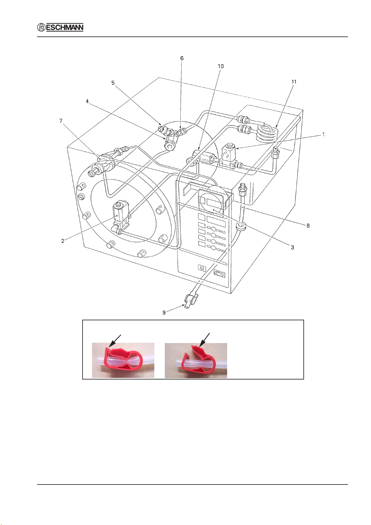
SES 2000 AUTOCLAVE Part 2
PART 2 DESCRIPTION
Push to open
1 Water fill valve
2 Discharge valve
3 Pressure gauge
4 Chamber manifold
5 Safety valve
6 Air valve
NOTE: On the latest units the copper pipes and fittings have been replaced by
plastic tubing and modified fittings. Refer to the parts list for more details.
Fig. 3 Autoclave: Pipes and Valves
ST-SM8l Page 13 of 43
Press to close
Current drain tap. Note
correct orientation and
location on drain tube.
7 Pressure door lock
8 Reservoir drain tube
9 Drain tap
10 Filter unit
11 Coil
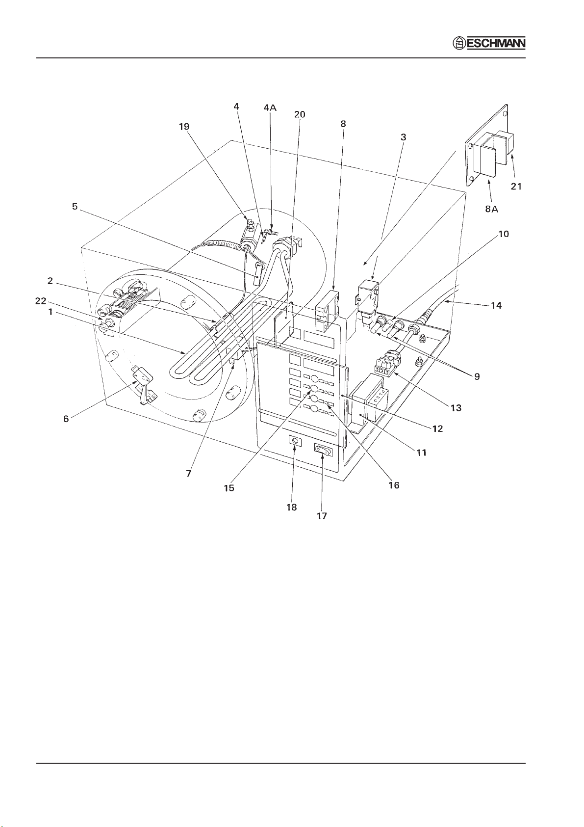
Part 2 SES 2000 AUTOCLAVE
PART 2 DESCRIPTION
Note: Items 4 and 4a are
fitted to the underside of
chamber manifold but
shown here for clarity.
1 Heating element
2 Thermostat sensor bulb
3 Cycling thermostat
4A Temperature sensor*
4 Sensor retaining plate
5 Water level sensor
6 Door interlock microswitch
7 Thermal fuse
8 Solid state relay
8A Solid state relay
(CE ONLY see note page 38)
9 Fuses (10A, 15A or 16A)
10 Fuse (400mA or 800mA)
* Autoclaves which incorporate a printer are fitted with two temperature sensors
Fig. 4 Autoclave: Heater and Process Controls
Page 14 of 43 ST-SM8l
11 Transformer
12 PCB (controller)
13 Terminal block
14 Power supply cable
15 Programme selector buttons
16 Light emitting diodes (LED’s)
17 Power on/off switch
18 Overheat warning lamp
19 Thermocouple entry port
20 Printer interface board
21 Mechanical relay (Relay protection
board) (CE ONLY see note page 38)
22 Solenoid door lock (CE ONLY see
note page 38)
Loading…
|
Название |
Скачать |
|
|
1. |
СТЕРИЛИЗАТОР ПАРОВОЙ DGM 130 РУКОВОДСТВО ПО ОБСЛУЖИВАНИЮ |
Скачать |
|
2. |
A-dec Lisa Sterilizer Service manual |
Скачать |
|
3. |
Cisa Series 200 MANUAL OF USE AND MAINTENANCE |
Скачать |
|
4. |
Cliniclave 45, 45M Руководство по эксплуатаци |
Скачать |
|
5. |
Cominox SterilClave 18-24 USE and MAINTENANCE MANUAL |
Скачать |
|
6. |
Eschmann Little Sister 3 Autoclave Service manual |
Скачать |
|
7. |
Eschmann LS5, SES2555, QuickVac Autoclave Service manual |
Скачать |
|
8. |
Eschmann SES 2000 Service manual |
Скачать |
|
9. |
Eschmann SES2000VAC Service manual |
Скачать |
|
10. |
Euronda E9 Inspection, Recorder, Med Sterilizer Service manual |
Скачать |
|
11. |
Getinge 86 Series Sterilizer Service manual |
Скачать |
|
12. |
Getinge 86 Series Sterilizer User manual |
Скачать |
|
13. |
Getinge 88 Series Sterilizer Service manual |
Скачать |
|
14. |
Getinge GE-224, Citomat 164 Sterilizer User and service manual |
Скачать |
|
15. |
Getinge VS 60, 90, 130 Vertical Sterilizer Service manual |
Скачать |
|
16. |
Hanshin HS-1212,1321,9041 Instruction manual |
Скачать |
|
17. |
Hirayama DON-450,650 Hot Air Oven Service manual |
Скачать |
|
18. |
Hirayama HRG-112/ 140 Autoclave Service manual |
Скачать |
|
19. |
Igea 2400 Sterilizer User and service manual |
Скачать |
|
20. |
KSG 40-60-2, 50-70-2, 50-80-2 Vertical Autoclave User and service manual |
Скачать |
|
21. |
KSG 30-50 vertical User and service manual |
Скачать |
|
22. |
KSG 50-80 vertical User and service manual |
Скачать |
|
23. |
Melag Euroklav 23 VS+ Euroklav 29 VS+ Руководство пользователя |
Скачать |
|
24. |
Melag Euroklav 23 VS+ Euroklav 29 VS+ Technical Manual |
Скачать |
|
25. |
Melag Vacuclav 41 B+, 43 B+ Руководство пользователя |
Скачать |
|
26. |
Melag Cliniclave 45, 45M Руководство по эксплуатации |
Скачать |
|
27. |
Midmark M9/M9D, M11/M11D Service and Parts Manual |
Скачать |
|
28. |
Midmark M9/M9D, M11/M11D Quick Reference Sheet |
Скачать |
|
29. |
Midmark M9, M9D, M11 User guide |
Скачать |
|
30. |
Midmark M11 UltraClave Installation & Operation Manual |
Скачать |
|
31. |
Midmark M7 SpeedClave Service and Parts Manual |
Скачать |
|
32. |
Midmark M7 SpeedClave Installation and Operation Manual |
Скачать |
|
33. |
Nuwe OT 020 Service manual |
Скачать |
|
34. |
Pelton & Crane DeltaQ Autoclave User manual |
Скачать |
|
35. |
Pelton & Crane OCM, OCR Sterilizer Service manual |
Скачать |
|
36. |
Pelton Crane Delta XL Sterilizer Service guide |
Скачать |
|
37. |
PMT DSV70 Steriliser Circuit diagram |
Скачать |
|
38. |
Reverberi Full Clave B16,B20 Service manual |
Скачать |
|
39. |
Reverberi Matika Service manual |
Скачать |
|
40. |
Reverberi Pratika B16-20 Sterilizer Service manual |
Скачать |
|
41. |
Reverberi Sterilix Baby Sterilizer Service manual |
Скачать |
|
42. |
SciCan Statim 2000 S,G4 Autoclave Service manual |
Скачать |
|
43. |
SciCan Statim 5000 Autoclave — Service manual |
Скачать |
|
44. |
SciCan Statim 5000 S,G4 Autoclave Service manual |
Скачать |
|
45. |
SciCan Statim 7000 Autoclave Service manual |
Скачать |
|
46. |
Selecta Autester E 30, 75, 140 Autoclave Service and user manual |
Скачать |
|
47. |
Selecta Autester ST Dry 17 Autoclave — Service and user manual |
Скачать |
|
48. |
Siltex Pratika B16-20 Maintenance manual |
Скачать |
|
49. |
Sirona DAC Autoclave Service manual |
Скачать |
|
50. |
Tuttnauer 4472/80 ИНСТРУКЦИЯ ПО ТЕХНИЧЕСКОМУ ОБСЛУЖИВАНИЮ И ЭКСПЛУАТАЦИИ |
Скачать |
Eschmann SES2000 Service Manual
- Addeddate
- 2020-05-19 23:34:03
- Classification
- Clinical;Sterilization;Eschmann Sterilizer;Eschmann SES 2000
- Identifier
- manual_Eschmann_SES2000_Service_Manual
- Identifier-ark
- ark:/13960/t20d3qw0z
- Ocr
- ABBYY FineReader 11.0 (Extended OCR)
- Page_number_confidence
- 86.67
- Ppi
- 300
- Scanner
- Internet Archive Python library 1.9.0
comment
Reviews
There are no reviews yet. Be the first one to
write a review.
603
Views
DOWNLOAD OPTIONS
Temporarily Unavailable
DAISY
For users with print-disabilities
Temporarily Unavailable
EPUB
Uploaded by
Sketch the Cow
on
Автоклав SES–серии — SES2000

Производитель:
Описание:
- SES2000 — паровой настольный автоклав
- Паровой настольный автоклав SES2000 — это настольный малогабаритный автоклав для быстрой стерилизации инструментария в условиях больниц, поликлиник, амбулаторий, кабинетов частных врачей, стоматологических кабинетов и лабораторий
- Автономные автоклавы используют непосредственно в предоперационной
- Экспресс-стерилизация — 3 мин 20 сек
| Технические характеристики | Короткий | Длинный |
|---|---|---|
| Размеры | ||
| Внешние: | 46 х 46 х 36 см | 46 х 65 х 36 см |
| Камеры: | Ø=20см, 35 см длина | Ø=20см, 50 см длина |
| Лотки: | 18 х 28 см (4 штуки) | 18 х 45 см (2 штуки) |
| Загрузка на лоток: | 1,5 кг на лоток | 3,5 кг на лоток |
| Полная загрузка камеры: | 6 кг на цикл | 7 кг на цикл |
| Вес | ||
| Нетто: | 27 кг | 35 кг |
| Брутто: | 32 кг | 40 кг |
| Электрика | ||
| Напряжение: | 230 V, 50/60 гЦ | 230 V, 50/60 гЦ |
| Мощность: | 2 кВт, 8.5 А | 2.75 кВт, 11.5 А |
| Конструкция | ||
| Камера: | нержавеющая сталь | нержавеющая сталь |
| Объём камеры: | 11 л | 16 л |
| Объём резервуара: | 2 л | 2 л |
| Лотки: | алюминиевый | нержавеющая сталь |
| Дверь: | нержавеющая сталь | нержавеющая сталь |
| Режимы стерилизации | ||
| Время стерилизации 134˚С: | 3 мин | 3 мин |
| Время стерилизации 121˚С: | 15 мин | 15 мин |
| Количество программ: | 4 | 4 |
| Полный цикл при 134˚С: | 12 мин | 13 мин |
| Полный цикл при 121˚С: | 24 мин | 24 мин |
| Время сушки | до 17 мин после стерилизации | |
| Рабочее давление | ||
| 134˚С | 205 кРа (2.05 бар) | 205 кРа (2.05 бар) |
| 121˚С | 105 кРа (1.05 бар) | 105 кРа (1.05 бар) |
| Для оформления заказа: | ||
| 230 V | 87 028 04 | 87 028 53 |
| 230 V с принтером | 87 028 12 | 87 028 61 |
Длительность полного цикла зависит от объёма загрузки, от окружающей температуры и от состояния автоклава


Описание Автоклав Little Sister 3 / SES 2000
Автоклав настольный Little Sister 3 / SES 2000 предназначен для дантистов, врачей общей практики, хирургов, ветеринаров и других врачей нуждающихся в стерилизации металлических инструментов немедленного использования.
— Ускоренный 12 минутный цикл
Цикл стерилизации при Т=134ºC, без цикла сушки, занимает всего 12 минут. Остальные три цикла возможны при Т=134ºC с сушкой и при Т=121º C с сушкой и без сушки. В указанное время включено время конденсации.
Управление «Одним касанием»
— Выберите цикл, нажатием одной клавиши на гигиенической панели управления, и Little Sister 3 начинает работать. Это так просто, каждый может работать с ним.
— Выбор размера камеры
Камеры имеют диаметр 20 см и стандартную длину 35см, так же существуют удлиненные камеры, длина которых 50см.
— Встроенный принтер*
Ко всем моделям SES 2000 (купить в Якутске)предлагается встроенный принтер для сохранения записей о каждом цикле.
* Все модели Little Sister 3 имеют встроенный принтер.
Достоинства Little Sister 3 / SES 2000:
— Быстрая стерилизация инструментов паром под давлением для немедленного применения
— Полезный объём камеры 11-16 литров
— Длина камеры 35-50 см
— Цельнолитая бесшовная камера из нержавеющих сплавов с гарантией на 10 лет
— Удобное и простое управление, выбор программы стерилизации путём нажатия соответствующей кнопки на пульте управления
— Полностью автоматизированный режим работы
— Отображение на панели управления информации о выбранной программе
— Цифровое измерение и отображение величины температуры и давления в камере в процессе стерилизации
— Отображение на дисплее проходящей фазы рабочего процесса
— Не требуется подключения к системе распределения пара, воды и к спускной трубе
— Встроенный бачок для дистиллированной воды, которая многократно используется для стерилизации.
— Возможна стерилизация изделий из стекла, металла и пластмассы
— Автоклав удобен для санитарной обработки, мытья, чистки и защиты от инфекции.
Технические характеристики Little Sister 3 / SES 2000:
|
Размеры автоклава |
||
|
Короткий |
Длинный |
|
|
Внешние: |
46см х 46см х36см |
46см х 65см х 36см |
|
Камеры: |
20см диам х 35см длина |
20см диам х 50см длина |
|
Лотки: |
18см х 28см (4 штуки) |
18см х 45см (2штуки) |
|
Загрузка на лоток: |
1,5кг на лоток |
3,5кг на лоток |
|
Полная загрузка камеры: |
6кг на цикл |
7кг на цикл |
|
Вес |
||
|
Нетто: |
27кг |
35кг |
|
Брутто: |
32кг |
40кг |
|
Электритрика: |
||
|
Напряжение: |
230V 50/60гЦ |
230V 50/60гЦ |
|
Мощность: |
2kW 8,5A |
2,75rW 11,5A |
|
Конструкция: |
||
|
Камера: |
Нержавеющая сталь |
Нержавеющая сталь |
|
Объём камеры: |
11 литров |
16 литров |
|
Объём резервуара: |
2 литра |
2 литра |
|
Лотки: |
Алюминиевый |
Нержавеющая сталь |
|
Дверь: |
Нержавеющая сталь |
Нержавеющая сталь |
|
Режимы стерилизации: |
||
|
Время стерилизации 134°С: |
3 минуты |
3 минуты |
|
Время стерилизации 121°С: |
15 минут |
15 минут |
|
Количество программ: |
4 |
4 |
|
Полный цикл при 134°С: |
12 минут |
13 минут |
|
Полный цикл при 121°С: |
24 минуты |
24 минуты |
|
Время сушки (если выбран режим с сушкой) |
до 17 минут после стерилизации |
|
|
Замечание: Длительность полного цикла зависит от объёма загрузки, от окружающей температуры и от состояния автоклава. |
||
|
Рабочие давления: |
||
|
134°С |
205 кРа (2,05 ваr) |
205 кРа (2,05 ваr) |
|
121°С |
105 кРа (1,05 ваr) |
105 кРа (1,05 ваr) |
|
Номер по каталогу: |
||
|
230V |
87-028-04 |
87-028-53 |
|
С принтером 230V |
87-028-12 |
87-028-61 |
Рзвернуть описание
Нет вопросов об этом товаре.