
19 октября 2016
В последнее время всё чаще появляются посты о приобретении мануалов по ремонту СГВ. Задался и я вопросом найти такое руководство, но в электронном виде. И нашёл. Обращаюсь к админам: Это не реклама, это реальная помощь всему братству сузуководов. У многих нет этакой книги, а приобрести нет возможности. Выкладываю ссылку на данное руководство, правда в черно-белом варианте.
docviewer.yandex.ru/?url=…jvu&page=1&c=580792b0eeb7
Можно скачать цветной вариант. Заходите по ссылке и сохраняйте в комп.
vk.com/doc-113732762_4372…423&dl=bb58be513eb3ad9ab8
Войдите или зарегистрируйтесь, чтобы писать комментарии, задавать вопросы и участвовать в обсуждении.
Все комментарии
Part No. 99011-66J21-03E
June, 2006
OWNER’S MANUAL
Keep With Vehicle At All Times.
Contains Important Information
On Safety, Operation & Maintenance.
2007
Prepared by
June, 2006
Part No. 99011-66J21-03E
Printed in Japan
TP286
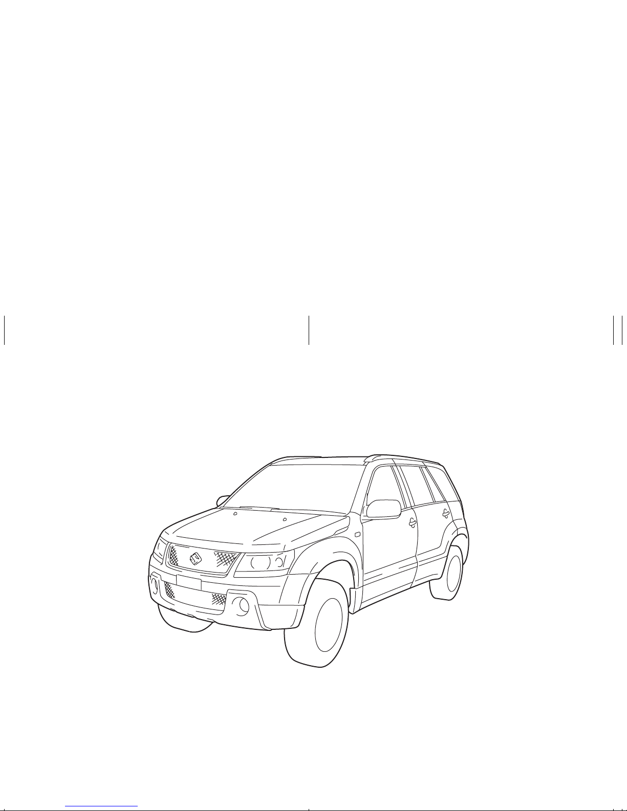
This owner’s manual applies to the GRAND VITARA series:
66J001
NOTE: The illustrated model is one of the GRAND VITARA series.
© COPYRIGHT SUZUKI MOTOR CORPORATION 2006
INTRODUCTION
Thank you for choosing SUZUKI and welcome to our growing family . Your choice was a wi se one; SUZUKI products are a g reat value
that will give you years of driving pleasure.
This Owner’s Manual was prepared to help you have a safe, enjoyable, and trouble-free experience with your SUZUKI. In it you will learn
about the vehicle’s operation, its safety features and maintenance requirements. Please read it carefully before operating your vehicle.
Afterwards, keep this Manual in the glove box for future reference.
Should you resell the vehicle, please leave this Manual with it for the next owner.
In addition to the Owner’s Manual, the other booklets provided with your SUZUKI explain the vehi cle’s warranties. We recommend you
read them as well to familiarize yourself with this important information.
When planning the regular scheduled maintenance of your SUZUKI, we recommend you visit your local SUZUKI dealership. Their fac-
tory-trained technicians will provide the best possible service and use only genuine SUZUKI parts and accessories.
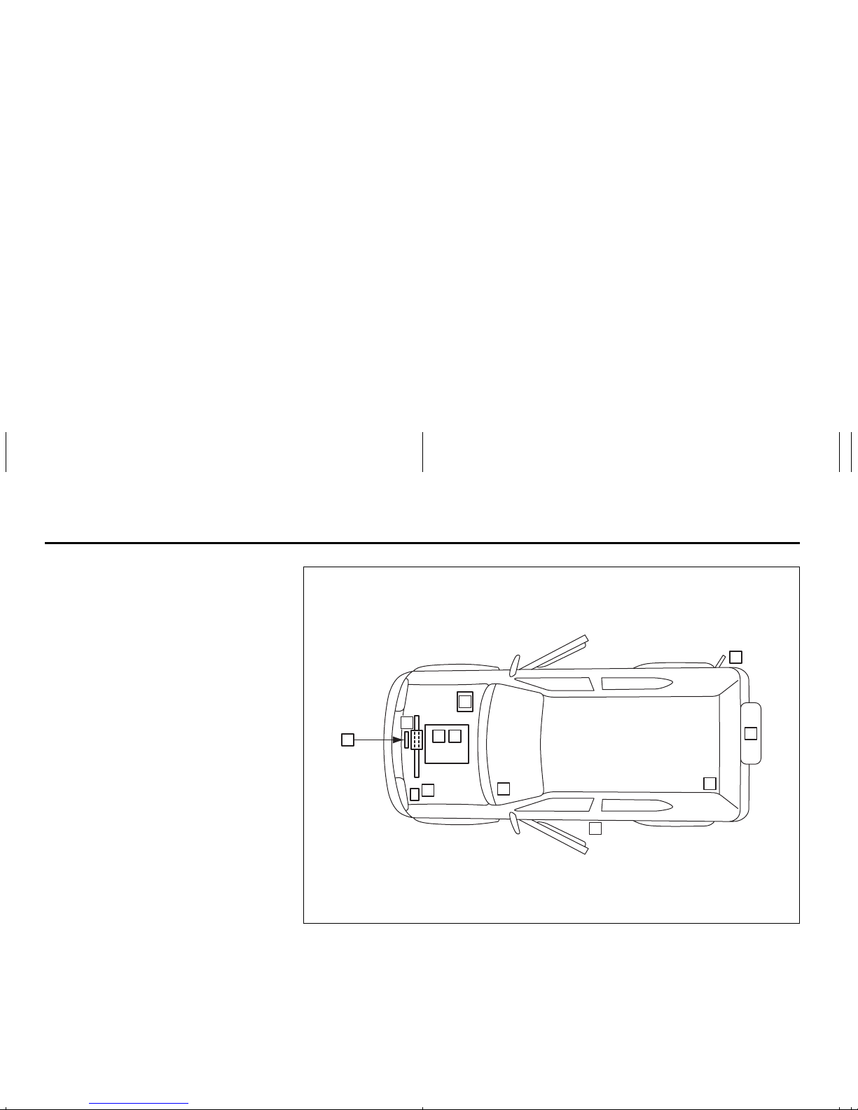
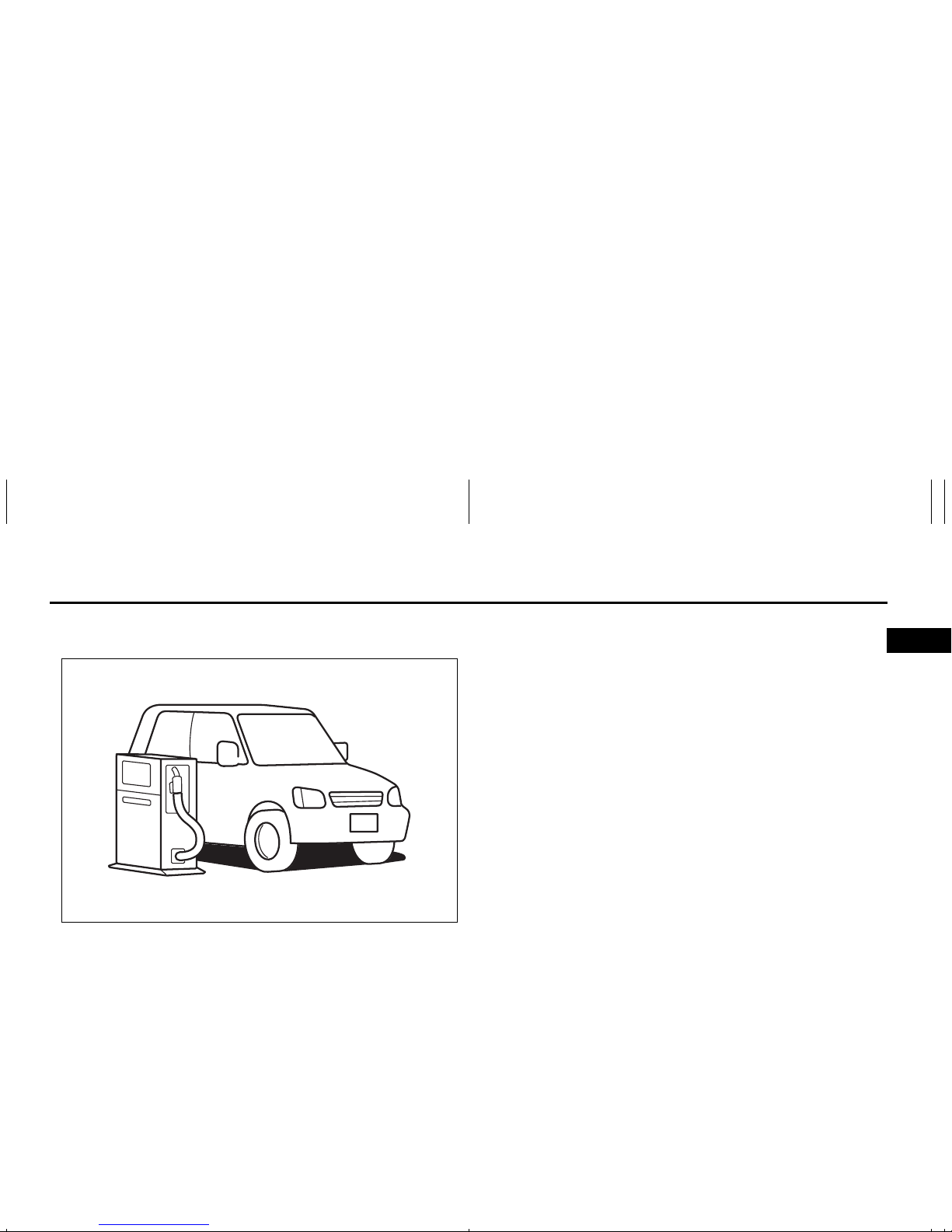
SERVICE STATION GUIDE
1. Fuel (see section 1)
2. Engine hood (see section 5)
3. Tire changing tools (see section 5)
4. Engine oil dipstick <Yellow>
(see section 9)
5. Automatic transmission fluid dipstick
<Red> (see section 9)
6. Engine coolant (see section 9)
7. Windshield washer fluid
(see section 9)
8. Battery (see section 9)
9. Tire pressure (see tire information
label on driver’s door lock pillar)
10. Spare tire (see section 9)
66J190
2
5
2
4
7
6
1
9
3
10
8

TABLE OF CONTENTS
California Proposition 65 Warning
WARNING
Engine exhaust, some of its consti tuents, and certain product components contain or emit chemicals
known to the State of California to
cause cancer and birth defects or
other reproductive harm.
FUEL RECOMMENDATION 1
BEFORE DRIVING 2
STEERING COLUMN CONTROLS 3
INSTRUMENT PANEL 4
OTHER CONTROLS AND EQUIPMENT 5
OPERATING YOUR VEHICLE 6
DRIVING TIPS 7
VEHICLE LOADING AND TOWING 8
INSPECTION AND MAINTENANCE 9
EMERGENCY SERVICE 10
APPEARANCE CARE 11
GENERAL INFORMATION 12
FUSES AND PROTECTED CIRCUITS 13
SPECIFICATIONS 14
INDEX 15
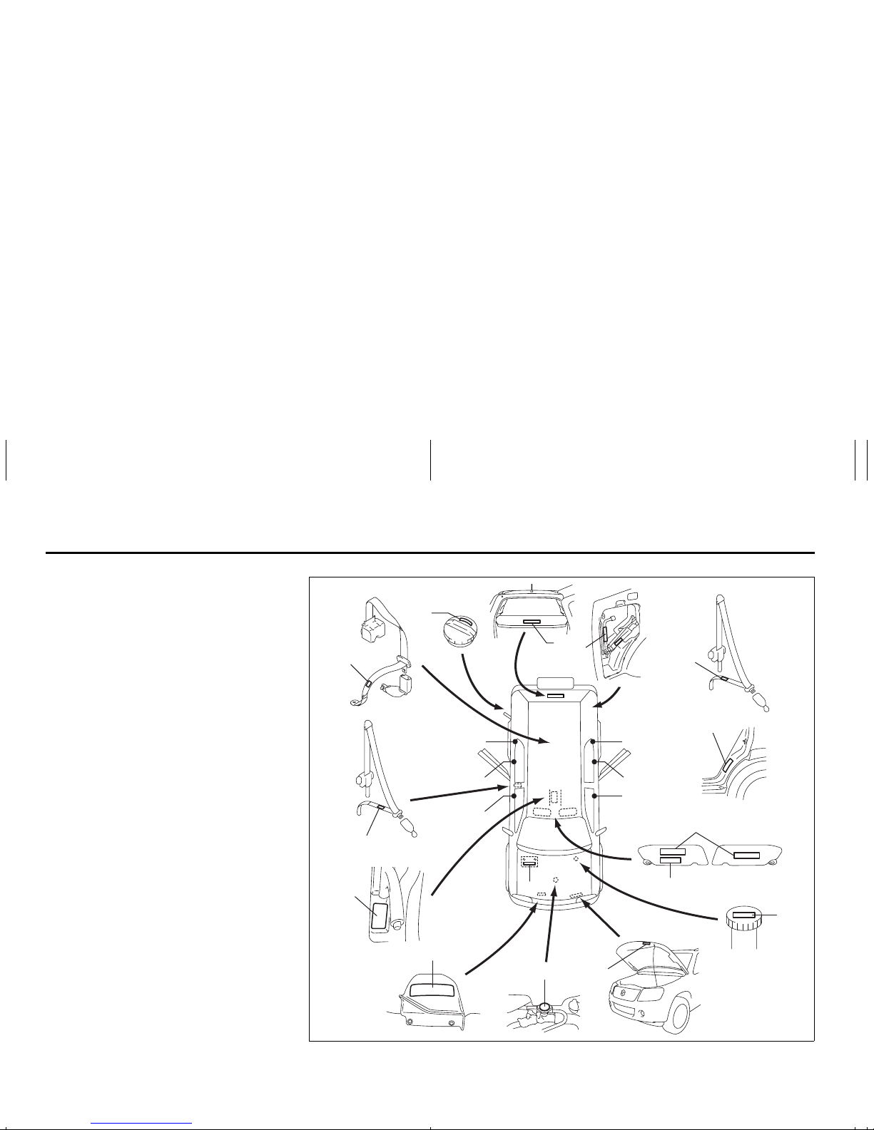
LOCATION OF WARNING
MESSAGES
Read and follow all of the warnings (labels
etc.) on your vehicle. Make sure you
understand all of them. Keep them on the
vehicle. Do not remove the messages for
any reason. If a label comes off or the
messages become difficult to be read,
have it corrected by your SUZUKI dealer.
1. Air bag warning labels
(on both sun visors)
2. Rollover warning label
3. Passenger seat belt warning label
4. Jacking warning label
5. Jacking warning label
6. Fuel filler cap message
7. Transfer switch warning label
8. Brake fluid cap message
9. Engine cooling fan warning lab e l
10. Radiator cap warning label
11. Air conditioner warning label
12. Battery label
13. Side air bag warning label
14. Rear outboard seat belt warning label
15. Rear center seat belt warning label
16. Luggage compartment cover warning
label
66J226
1
2
3
6
8
12
13
4
16
14
15
14
7
9
11
10
14
13
13 13
13
Driver Passenger
Location of Warning Messages: 1, 2, 3, 4, 5, 6, 7, 8, 9, 10,
14

0-1
FOREWORD
Your SUZUKI multipurpose vehicle is
designed and built to be capable of performing both on pavement and off road.
You should therefore remember that your
vehicle is distinctly different from ordinary
passenger cars in handling as well as in
structure. As with other vehicles of this
type, failure to operate this vehicle correctly may result in loss of control or an
accident. Be sure to read “Important Vehicle Design Features to Know” and the “onpavement” and “off-road” driving guidelines
which follow. It is very important to familiarize yourself with the proper operation of
this vehicle before you start driving.
All information in this manual is based
on the latest product information available at the time of publication. Due to
improvements or other changes, there
may be discrepancies between information in this manual and your vehicle.
SUZUKI MOTOR CORPORATION
reserves the right to make production
changes at any time, without notice and
without incurring any obligation to
make the same or similar changes to
vehicles previously built or sold.
SUZUKI MOTOR CORPORATION
believes in conservation and protection of
Earth’s natural resources.
To that end, we encourage every vehi cle
owner to recycle, trade in, or properly dispose of, as appropriate, used motor oil,
coolant, and other fluids, batteries and
tires.
IF YOU HAVE ANY PROBLEMS WITH
YOUR SUZUKI:
Please review the New Vehicle Warranty
Information booklet supplied with your
SUZUKI. Should you have a question or
problem regarding the warranty or service
of your vehicle, please take the following
action:
Consult the Service Manager and the
Owner of the Suzuki Automotive Dealership. Explain your problem and ask for
their assistance in resolving your problem.
The Owner of the dealership is in the very
best position to assist you as he or she is
vitally concerned with your continued satisfaction.
If you are still in need of additional information, or if you are dissatisfied, request that
your dealer arrange a meeting with your
District Service Manager.
If, after doing so, you still require further
assistance, and you purchased your
SUZUKI in the continental United States,
please contact the American Suzuki Customer Relations Department by telephone
at 1-800-934-0934 or in writing at:
American Suzuki Motor Corporation
Automotive Customer Relations
3251 East Imperial Highway
Brea, CA 92821-6795
0-2
If you purchased your SUZUKI in Canada
please contact the Suzuki Canada Customer Relations Department by telephone
at 1-905-889-2677 extension 2254 or in
writing at:
Suzuki Canada Inc.
Customer Relations
100 East Beaver Creek Road
Richmond Hill, On
L4B 1J6
In the event you require assistance related
to your SUZUKI, while temporarily travelling in either the United States or Canada,
you may wish to contact the Suzuki Customer Relations Department directly of the
country in which you are temporarily operating your vehicle.
Please be certain to provide us with the following information: the model, Vehicle
Identification Number, mileage, accessories involved, event dates, your concern,
and any other comments which you may
have. When we receive your correspondence, we will be pleased to contact the
Owner of your dealership and assist in
resolving your concern.
For owners outside the continental United
States, please refer to the distributor’s
address listed in your Warranty Information
booklet.
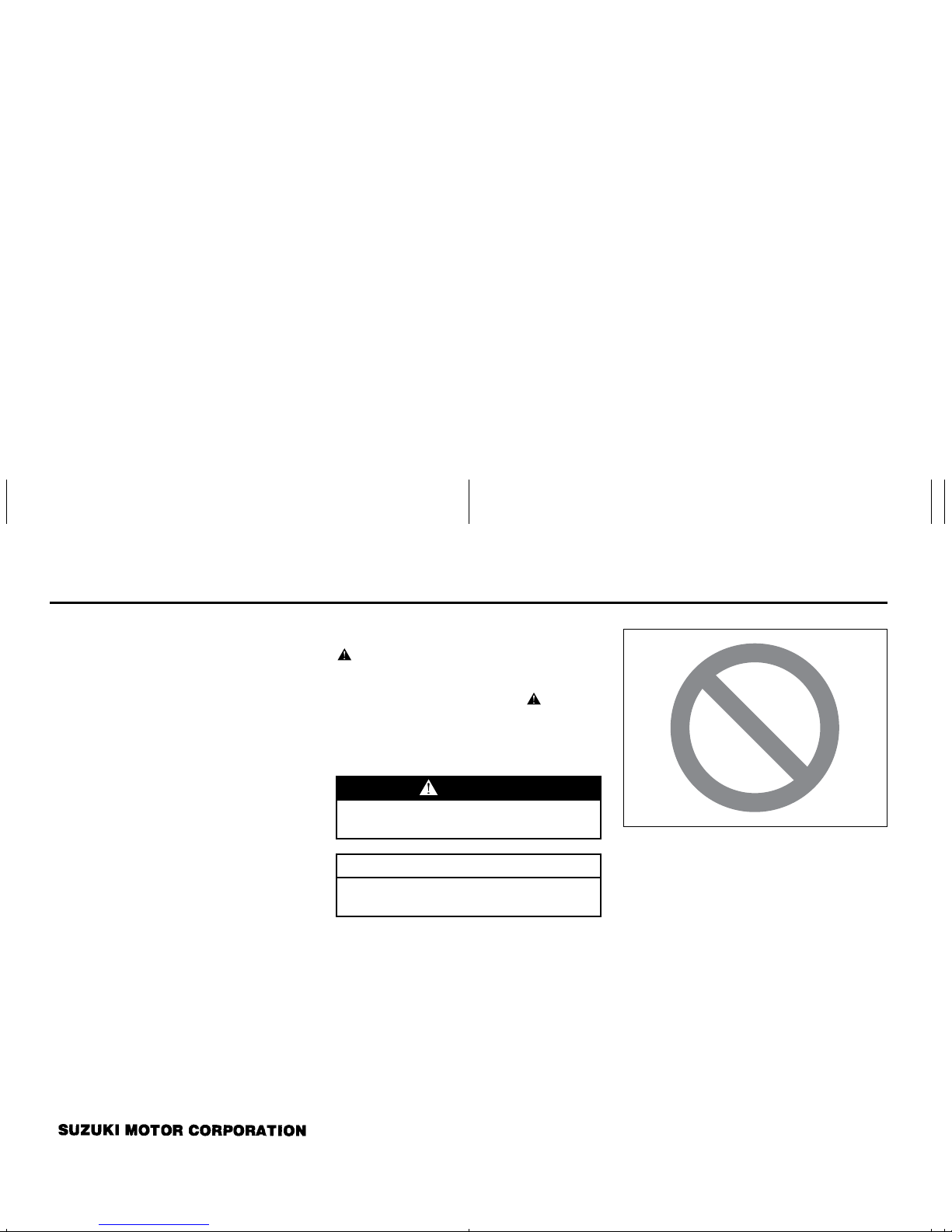
IMPORTANT
WARNING/CAUTION/NOTE
Please read this manual and follow its
instructions carefully. To emphasize special information, the symbol and the
words WARNING, CAUTION and NOTE
have special meanings. Pay special attention to the messages highlighted by these
signal words:
NOTE:
Indicates special information to make
maintenance easier or instructions clearer.
75F135
The circle with a slash in this manual
means “Don’t do this” or “Don’t let this happen”.
WARNING
Indicates a potential hazard that
could result in death or injury.
CAUTION
Indicates a potential hazard that
could result in vehicle damage.
0-3
MODIFICATION WARNING LEAK DETECTION PUMP
NOTE:
Your vehicle has a pump to regularly check
the vehicle’s evaporative emission control
system for leaks. This check is performed
approximately five hours after the engine is
turned off. During this leak check, you may
hear a sound coming from the vehicle for
several minutes. This sound is normal and
does not indicate a malfunction.
WARNING
Do not modify this vehicle. Modification could adversely affect safety,
handling, performance or durability
and may violate governmental regulations. In addition, damage or performance problems resulting from
modification may not be covered
under warranty.
CAUTION
Improper installation of mobile communication equipment such as cellular telephones or CB (Citizen’s Band)
radios may cause electronic interference with your vehicle’s ignition system, resulting in vehicle performance
problems. Consult your SUZUKI
dealer or qualified service technician
for advice on installing such mobile
communication equipment.
FUEL RECOMMENDATION
1
65D394
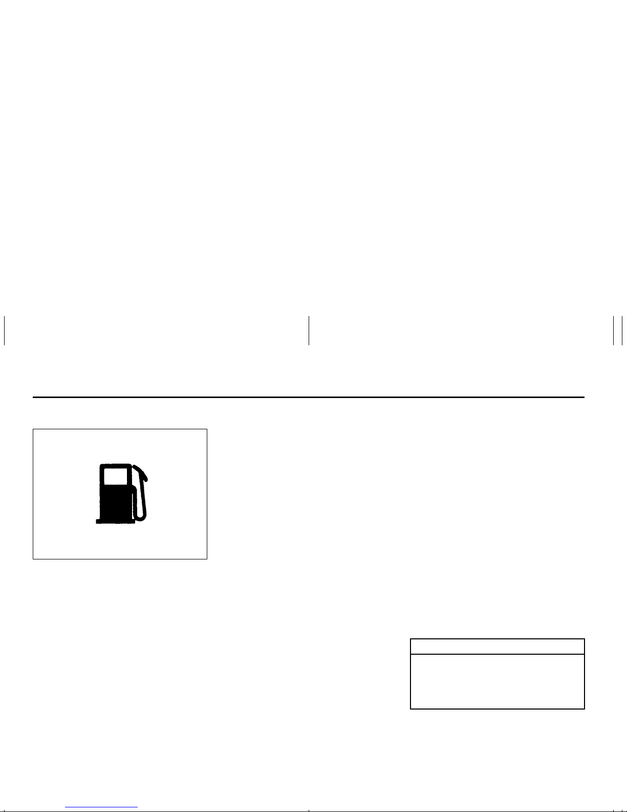
FUEL RECOMMENDATION
Fuel Recommendation ………………………………………………..1-1
1-1
FUEL RECOMMENDATION
Fuel Recommendation
60A004
Your vehicle requires regular unleaded
gasoline with a minimum rating of 87 pump
octane ((R + M)/2 method). In some areas,
the only fuels that are available are oxygenated fuels.
Oxygenated fuels which meet the minimum octane requirement and the requirements described below may be used in
your vehicle without jeopardizing the New
Vehicle Limited Warranty.
NOTE:
Oxygenated fuels are fuels which contain
oxygen-carrying additives such as MTBE
or alcohol.
Gasoline Containing MTBE
Unleaded gasoline containing MTBE
(methyl tertiary butyl ether) may be used in
your vehicle if the MTBE content is not
greater than 15%. This oxygenated fuel
does not contain alcohol.
Gasoline/Ethanol blends
Blends of unleaded gasoline and ethanol
(grain alcohol), also known as gasohol,
may be used in your vehicle if the ethanol
content is not greater than 10%.
Gasoline/Methanol blends
Fuels containing 5% or less methanol
(wood alcohol) may be suitable for use in
your vehicle if they contain cosolvents and
corrosion inhibitors. Do NOT USE fuels
containing more than 5% methanol under
any circumstances. Fuel system damage
or vehicle performance problems resulting
from the use of such fuels are not the
responsibility of SUZUKI and may not be
covered under the New Vehicle Limited
Warranty.
Fuel Pump Labeling
In some states, pumps that dispense oxygenated fuels are required to be labeled for
the type and percentage of oxygenate and
whether important additives are present.
Such labels may provide enough information for you to determine if a particular
blend of fuel meets the requirements listed
above. In other areas, pumps may not be
clearly labeled as to the content or type of
oxygenate and additives. If you are not
sure that the fuel you intend to use meets
these requirements, check with the service
station operator or the fuel supplier.
NOTE:
To help clean the air, SUZUKI recommends you use the oxygenated fuels.
However, if you are not satisfied with the
driveability or fuel economy of your vehicle
when you are using an oxygenated fuel,
switch back to the regular unleaded gasoline.
CAUTION
Be careful not to spill fuel containing
alcohol while refueling. Fuels containing alcohol can cause paint damage, which is not covered under the
New Vehicle Limited Warranty.
Fuel Recommendation: 1, 2
BEFORE DRIVING
2
60G404
BEFORE DRIVING
Keys …………………………………………………………………………..2-1
Spare Tire Nut Lock (if equipped) ………………………………..2-1
Door Locks ……………………………………………………………….. 2-2
Windows …………………………………………………………………… 2-14
Mirrors ……………………………………………………………………….2-16
Seat Adjustment …………………………………………………………2-17
Head Restraints …………………………………………………………. 2-19
Seat Belts and Child Restraint Systems ……………………… 2-20
Supplemental Restraint System (air bags) ………………….. 2-37
2-1
BEFORE DRIVING
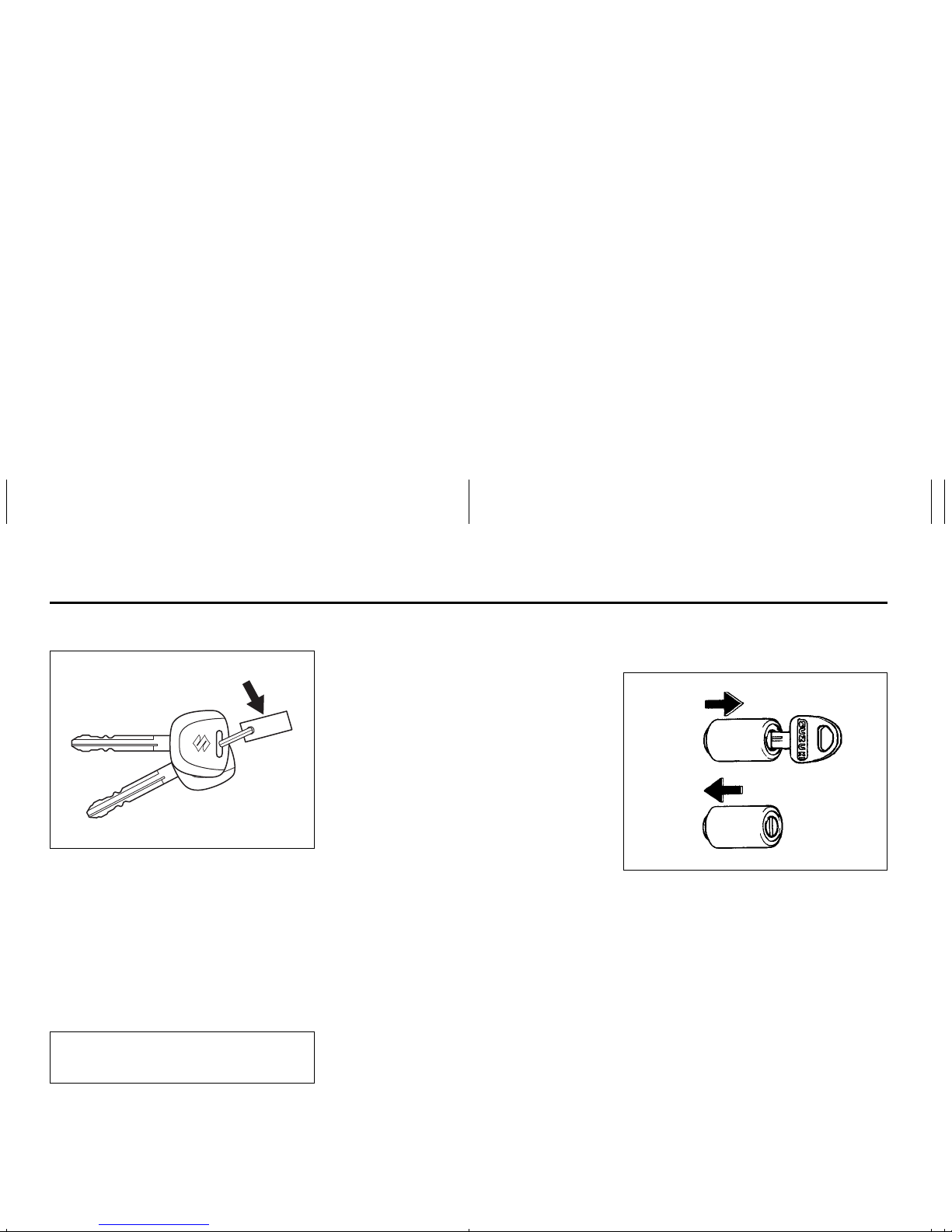
Keys
54G489
Your vehicle comes with a pair of identical
keys. Keep the spare key in a safe place.
One key can open all of the locks on the
vehicle.
The key identification number is stamped
on a metal tag provided with the keys.
Keep the tag in a safe place. If you lose
your keys, you will need this number to
have new keys made. Write the number
below for your future reference.
Ignition Key Reminder
A buzzer sounds intermittently to remind
you to remove the ignition key if it is in the
ignition switch when the driver’s door is
opened.
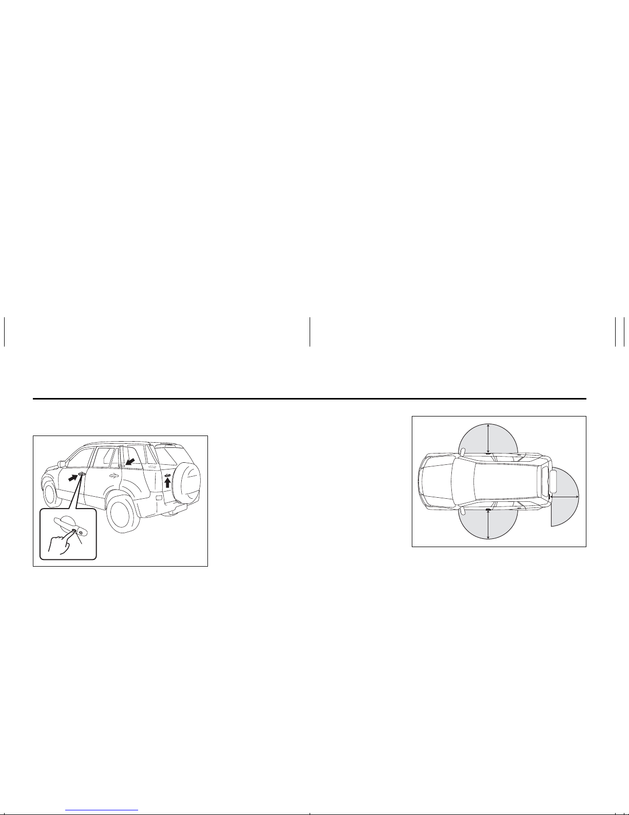
Spare Tire Nut Lock
(if equipped)
64J172
A nut lock is used for the spare tire. To
unlock the spare tire nut, insert the ignition
key into the lock as far as the key will go
and remove the lock with the key in. To lock
the spare tire nut, put the lock on the nut
and push the lock in.
KEY NUMBER:
EXAMPLE
To LOCK
To UNLOCK
Keys: 8
Spare Tire Nut Lock: 5
2-2
BEFORE DRIVING
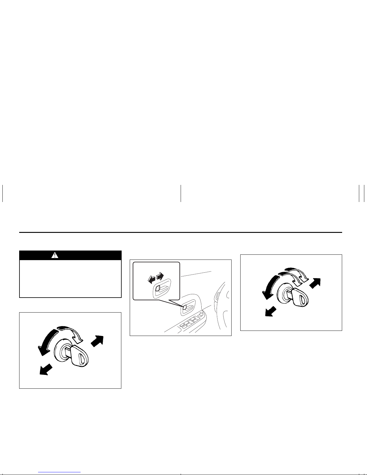
Door Locks
Side Door Locks
60A009
To lock a front door from outside the vehicle:
• Insert the key and turn the top of the key
toward the front of the vehicle, or
• Turn the lock knob forward and close the
door.
To unlock a front door from outside the
vehicle, insert the key and turn the top of
the key toward the rear of the vehicle.
64J002
To lock a door from inside the vehicle, turn
the lock knob forward. Turn the lock knob
rearward to unlock the door.
To lock a rear side door from outside the
vehicle, turn the lock knob forward and
close the door.
Power Door Locking System
(if equipped)
64J003
You can lock and unlock all doors simultaneously by:
• Turning the key in the driver’s door lock,
or
• Pushing the power door locking switch
located on the door panel of either front
door.
(when using the key)
To lock all doors simultaneously, insert the
key in the driver’s door lock, and turn the
key to the LOCK side.
To unlock all doors simultaneously, insert
the key in the driver’s door lock and turn
the key to the UNLOCK side twice.
WARNING
Always lock all doors when driving.
Locking the doors helps to prevent
occupants from being thrown from
the vehicle in the event of an accident. It also helps prevent unintended opening of the doors.
Rear
Front
LOCK
UNLOCK
UNLOCK LOCK
UNLOCK
Rear
Front
LOCK
Door Locks: 3, 5, 8
2-3
BEFORE DRIVING
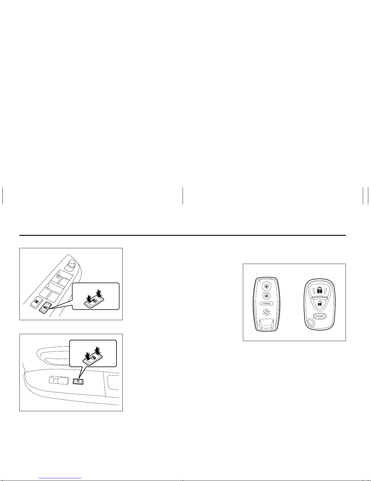
Driver’s side
64J004
Front passenger’s side
66J012
(when using the power door locking
switch)
To lock or unlock all the doors simultaneously, depress the front or rear of the
switch respectively.
NOTE:
• If your vehicle is equipped with the keyless entry system, you can also lock or
unlock all doors by operating the transmitter. Refer to “Keyless Entry System”
in this section.
• If your vehicle is equipped with the keyless start system, you can also lock or
unlock all doors by pushing the request
switch on the door handle. Refer to “Keyless Start System” in this section.
Keyless Start System Remote
Controller/Keyless Entry System
Transmitter
66J111
Your vehicle is equipped with either a keyless start system remote controller (Type
A) or a keyless entry system transmitter
(Type B). The remote controller has a keyless entry system and a keyless start system. The transmitter has only a keyless
entry system. For details, refer to the following explanations.
Keyless Start System Remote
Controller (Type A)
The remote controller enables the following
operations:
• You can lock or unlock the doors by
operating the LOCK/UNLOCK buttons
on the remote controller. Refer to the
explanation in this section.
EXAMPLE
UNLOCK LOCK
UNLOCKLOCK
Type A Type B
Door Locks: 3, 5, 8
2-4
BEFORE DRIVING
• You can lock or unlock the doors by
pushing the request switch on the door
handle. For details, refer to the explanation in this section.
• You can start the engine without using
an ignition key. For details, refer to “Ignition Switch” in the “STEERING COLUMN CONTROLS” section and “Starting
the Engine” in the “OPERATING YOUR
VEHICLE” section.
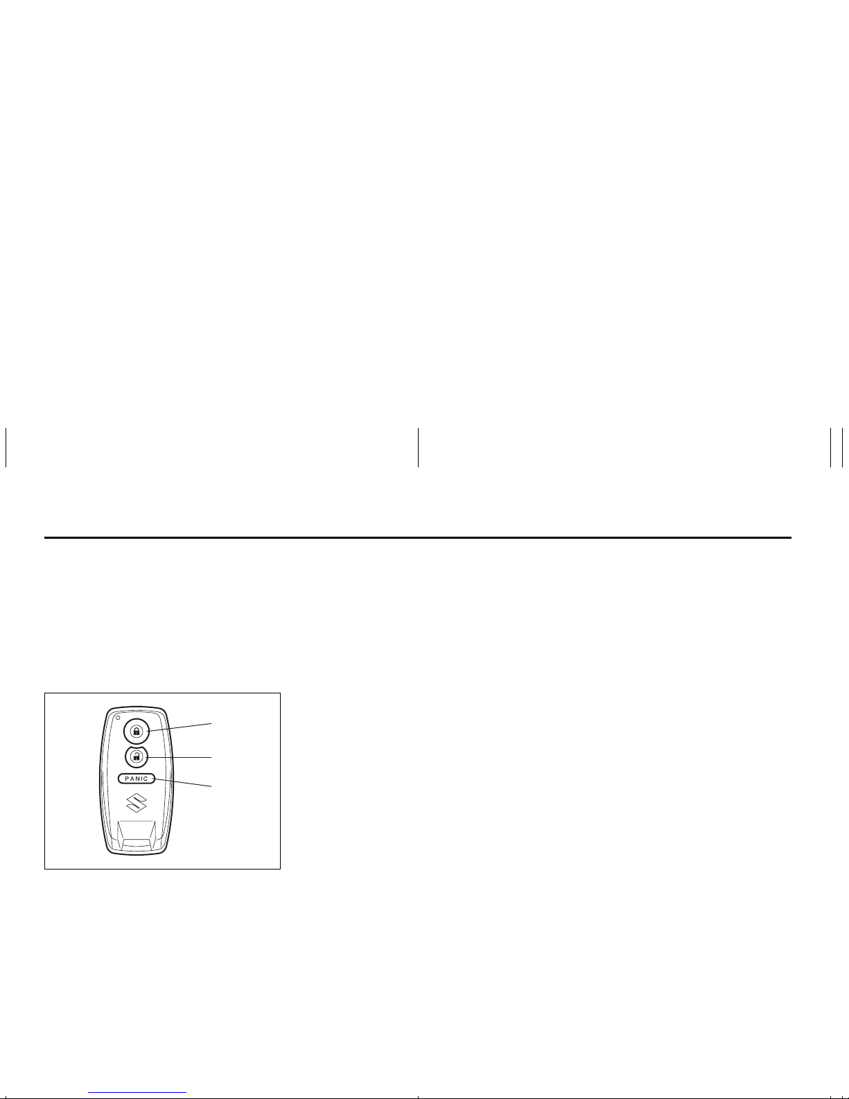
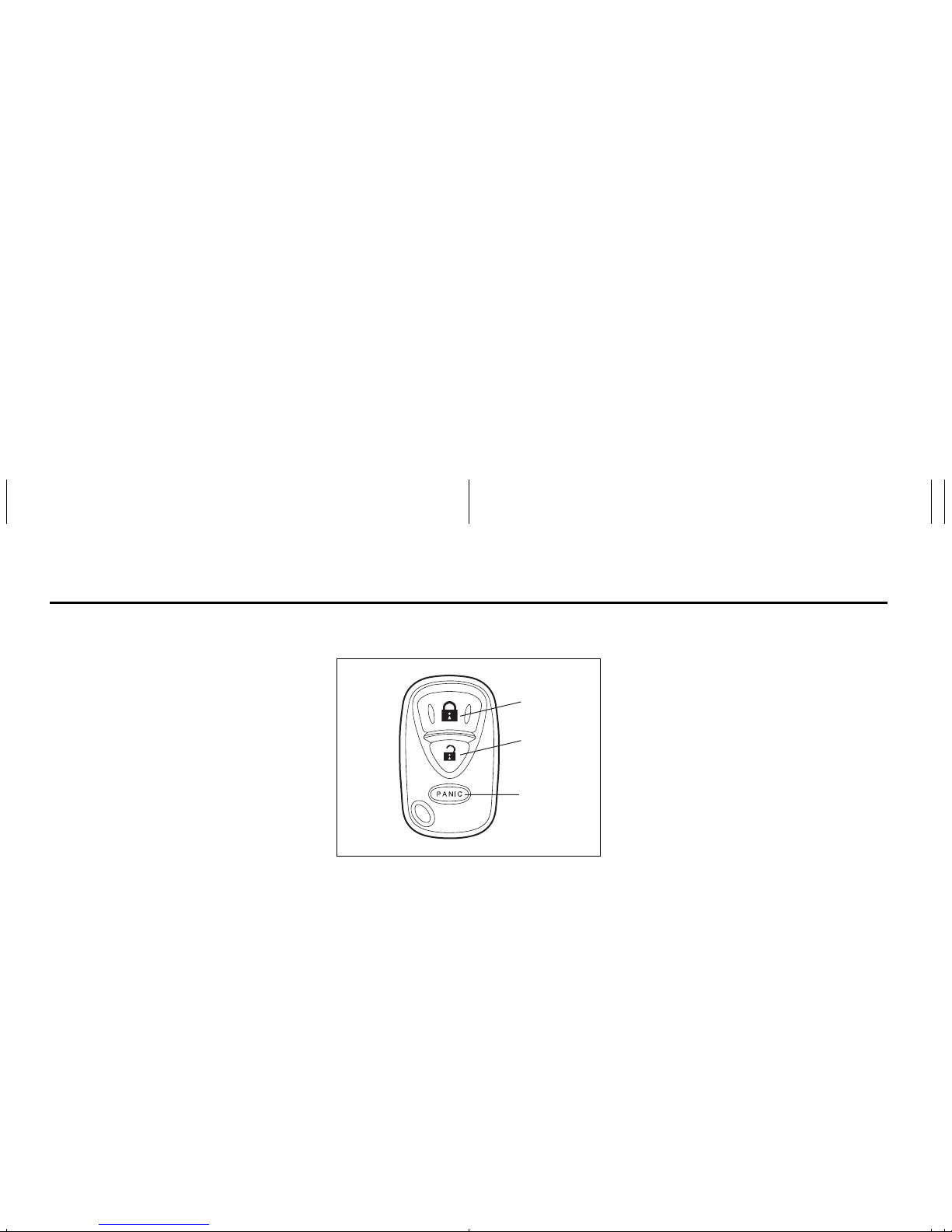
66J114
(1) “LOCK” button
(2) “UNLOCK” button
(3) “PANIC” button
“LOCK” button (1) / “UNLOCK” button
(2) function
You can lock or unlock all doors simultaneously by operating the remote controller
near the vehicle.
• To lock the doors, push the “LOCK” button (1).
• To unlock the driver’s door, push the
“UNLOCK” button (2) once.
• To unlock other doors, wait a second or
two, then push the “UNLOCK” button (2)
a second time. If you “double-click” too
fast, the doors will not unlock.
When the doors are locked, the turn signal
lights will flash once.
When the doors are unlocked:
• The turn signal lights will flash twice.
• If the interior light switch is in the midd le
position, the interior light will turn on for
about 15 seconds and then fade out. If
you push in the ignition switch or insert
the key during this time, the light will
start to fade out immediately.
Be sure the doors are locked after you
operate the “LOCK” button. If no door is
opened within about 30 seconds after the
“UNLOCK” button is operated, the doors
will automatically lock again.
NOTE:
• The maximum operating distance of the
remote controller is about 5 m (16 ft.),
but this can vary depending on the surroundings, especially near other transmitting devices such as radio towers or
CB (Citizen’s Band) radios.
• The door locks can not be operated with
the remote controller if the ignition switch
is in a position other than “LOCK”, or the
ignition key is inserted in the ignition
switch.
If any door is open, you cannnot lock the
door by operating the remote controller,
however unlock the door.
• You cannot lock the door unless all of
the doors are closed completely.
• If you lose one of the remote controllers,
ask your SUZUKI dealer as soon as possible for a replacement. Be sure to have
your dealer program the new remote
controller code in your vehicle’s memory
so that the old code is erased, or perform the programming procedure yourself according to the instructions in this
section.
“PANIC” button (3) function
This function is to get the attention of others.
Press the “PANIC” button (3) for more than
1 second. The headlights and taillights will
blink for about 30 seconds. Also, the horn
will sound intermittently for about 30 seconds at the same time.
To cancel the “PANIC” mode, press any
button (PANIC, LOCK or UNLOCK) on the
remote controller. You can also insert the
key in the ignition switch and turn to the
“ON” position to cancel the “PANIC” mode.
NOTE:
The “PANIC” button function will not activate when the key is in the ignition switch.
(1)
(2)
(3)
Door Locks: 3, 5, 8
2-5
BEFORE DRIVING
Keyless unlocking/locking using the
request switches
64J006
When the remote controller is within the
operating range described in this section,
you can lock or unlock the doors by pushing the request switch (1) on the door handle of the driver’s door, front passenger’s
door or rear door.
To lock all doors when all doors are
unlocked:
• Push the request switch on one of the
door handles once.
The turn signal lights will flash once when
the doors are locked.
To unlock a door or all doors:
• Push the request switch on the door
handle once to unlock only one door.
• Push the request switch on the door
handle twice to unlock all doors.
When the doors are unlocked:
• The turn signal lights will flash twice.
• If the interior light switch is in the midd le
position, the interior light will turn on for
about 15 seconds and then fade out. If
you push in the ignition switch or insert
the key during this time, the light will
start to fade out immediately.
Be sure the doors are locked after you
operate the request switch to lock the
doors.
NOTE:
• The door locks can not be operated by
the request switch under the following
conditions:
– If any door is open or is not completely
closed.
– If the ignition switch is in a position
other than “LOCK”.
– If the ignition key is inserted in the igni-
tion switch.
• If no doors are opened within about 30
seconds after unlocking the doors by
pushing the request switch, the doors
will be locked again automatically.
66J163
(1) 80 cm (2 1/2 feet)
When the remote controller is within
approximately 80 cm (2 1/2 feet) from a
front door handle or the rear door handle,
you can lock or unlock the doors by pushing the request switch on the door handle.
NOTE:
• If the remote controller is outside the
request switch operating range
described above, you will not be able to
operate the request switch.
• If the battery of the remote controller
runs down or there are strong radio
waves or noise, the request switch operating range may be reduced or the
remote controller may be inoperative.
• If the remote controller is too close to the
door glass, the request switches may not
operate.
(1)
EXAMPLE
(1)
(1)
(1)
EXAMPLE
Door Locks: 3, 5, 8
2-6
BEFORE DRIVING
• If a spare remote controller is in the vehicle, the request switches may not operate normally.
• The remote controller will only operate a
request switch if it is within the switch’s
operating range. For example, if the
remote controller is within the operating
range of the driver’s door request switch
but not the front passenger’s door
request switch or the rear door request
switch, the driver’s door switch can be
operated but the front passenger’s door
switch or rear door switch can not be
operated.
NOTE:
The keyless start system may not function
correctly in certain environments or under
certain operating conditions such as the
following:
• When there are strong signals coming
from a television, power station or a cellular phone.
• When the remote controller is in contact
with or covered by a metal object.
• When a radio wave type remote keyless
entry is used nearby.
• When the remote controller is placed
near an electronic device such as personal computer.
Some additional precautions you should
take and information you should be aware
of are:
• Make sure the ignition key is stowed in
the remote controller. If the remote controller becomes unreliable, you will not
be able to lock or unlock the doors or
start the engine.
• Be sure that the driver always carries the
remote controller.
• If you lose one of the remote controllers,
ask your SUZUKI dealer as soon as possible for a replacement. Be sure to have
your dealer program the new remote
controller code in your vehicle’s memory
so that the old code is erased, or perform the programming procedure yourself according to the instructions in this
section.
• You can use up to four remote controllers
and ignition keys for your vehicle. Ask
your SUZUKI dealer for details.
• The battery life of the remote controller
is about two years, but it can vary
depending on usage conditions.
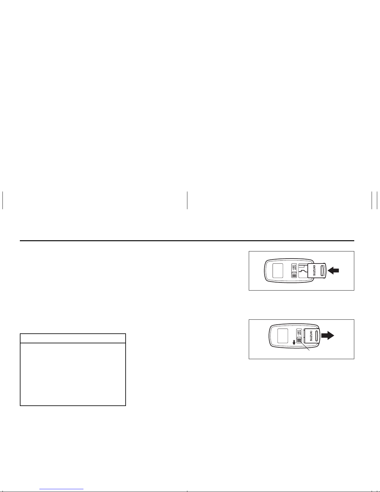
66J013
To stow the ignition key into the remote
controller, push the key in the remote controller until you hear a click.
66J014
To remove the key from the remote controller, push the button (A) in the direction of
the arrow and pull the key out from the
remote controller.
CAUTION
The remote controller is a sensitive
electronic instrument. To avoid damaging the remote controller:
• Do not expose it to impacts, moisture or high temperature such as
by leaving it on the dashboard
under direct sunlight.
• Keep the remote controller away
from magnetic objects such as a
television.
(A)
Door Locks: 3, 5, 8
2-7
BEFORE DRIVING
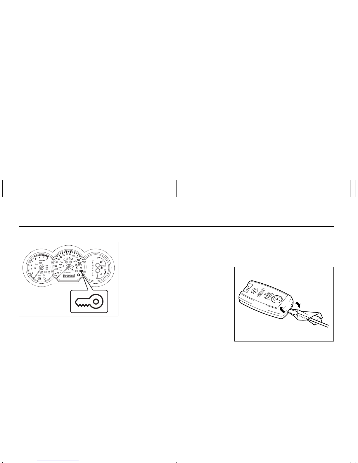
Reminder function
66J022
If the remote controller is not in the vehicle
under the following conditions, a buzzer
sounds intermittently for about 2 seconds
and the keyless start system indicator light
on the instrument cluster blinks in red:
• When the vehicle speed is over 10 km/h
(6 mph).
• When one or more doors are opened
and all of the doors are later closed with
the ignition switch in a position other
than “LOCK”.
The red indicator light will turn off within
several seconds after the remote controller
is returned to an area of the vehicle other
than the rear luggage area.
If the remote controller is left in the vehicle
and you lock the driver’s door or front passenger’s door as described below, the door
will be automatically unlocked.
• If you open the driver’s door and lock the
door by turning the lock knob forward or
pushing the power door locking switch,
the driver’s door will be automatically
unlocked.
• If you open a door other than the driver’s
door and lock the front passenger’s door
by turning the lock knob forward or pushing the power door locking switch, the
front passenger’s door will be automatically unlocked.
NOTE:
• The reminder will not operate when the
remote controller is on the instrument
panel, in the glove box, in the door
pocket, in the sun visor or on the floor
etc.
• Be sure that the driver always carries the
remote controller.
• Do not leave the remote controller in the
vehicle when leaving the vehicle.
Replacement of the battery
If the remote controller becomes unreliable, replace the battery.
To replace the battery of the remote controller:
66J016
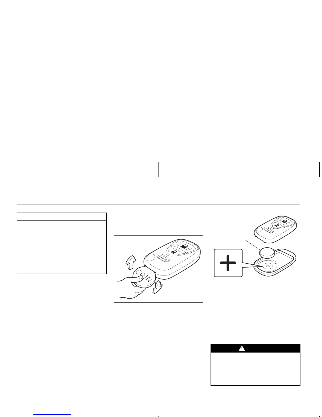
1) Insert a flat blade screw driver covered
with a soft cloth in the slot of the remote
controller and pry it open.
EXAMPLE
Door Locks: 3, 5, 8
2-8
BEFORE DRIVING
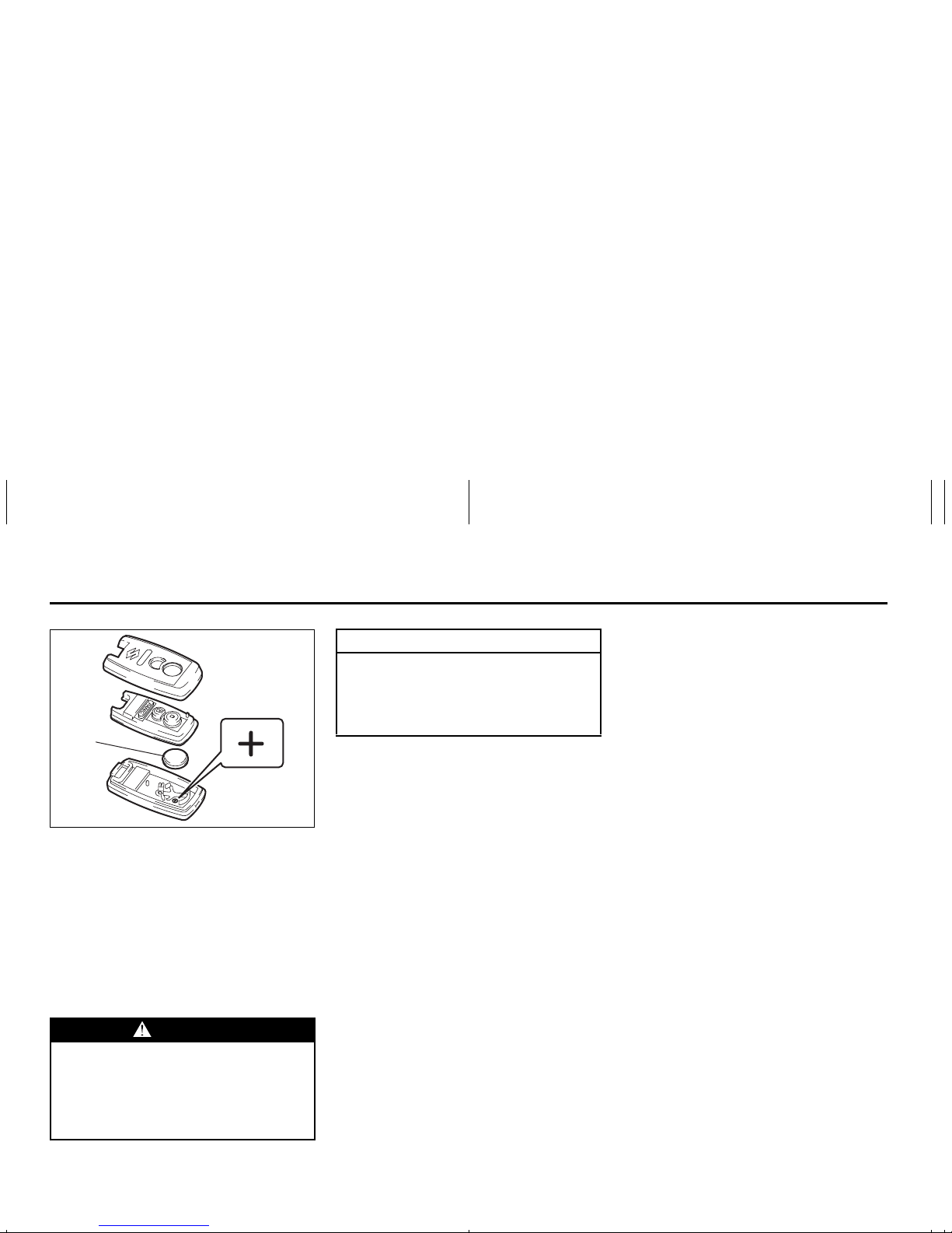
66J017
2) Replace the battery (1) (Lithium disc
type CR2032 or equivalent) so its + terminal faces the bottom of the case as
shown in the illustration.
3) Close the remote controller firmly.
4) Make sure the door locks can be operated with the remote controller.
5) Dispose of the used battery properly
according to applicable rules or regulations. Do not dispose of lithium batteries with ordinary household trash.
Programming/erasing the remote controller code yourself
Your new vehicle was originally equipped
with two remote controllers.
If you have lost one of the remote controllers, you should change the remote controller code in your vehicle’s memory as
soon as possible for security. If you purchase additional remote controllers, the
new remote controllers need to be programmed into your vehicle’s memory. You
can perform this yourself by using the following procedure:
NOTE:
• You can program up to four remote controller codes into your vehicle’s memory.
The four codes may be the same or different.
• If you try to program a fifth code, the four
remote controller codes that are programmed will be cleared automatically.
• If you program a new remote controller
code, all of the old remote controller
codes that are in your vehicle’s memory
will be erased automatically. When you
program a new remote controller, you
should reprogram any additional remote
controllers at the same time.
• To purchase new remote controllers, see
your SUZUKI dealer.
• Before you begin programming, have all
of your remote controllers available.
WARNING
Swallowing a lithium battery may
cause serious internal injury. Do not
allow anyone to swallow a lithium
battery. Keep lithium batteries away
from children and pets. If swallowed,
contact a physician immediately.
(1)
CAUTION
The transmitter/remote controller is a
sensitive electronic instrument. To
avoid damaging it, do not expose it to
dust or moisture or tamper with internal parts.
Door Locks: 3, 5, 8
2-9
BEFORE DRIVING
To program a new remote controller
1) Close all the doors of the vehicle.
2) Sit in the driver’s seat and confirm that
the driver’s door is unlocked.
3) Insert the key into the ignition switch.
4) Complete steps 1 through 6 described
below within 25 seconds after step 3).
64J004
1. Push the power door locking switch
of the driver’s door to the lock position and then push it to the unlock
position.
2. Repeat step 1 two more times.
3. Push the power door locking switch
of the driver’s door to the lock position.
4. Remove the key from the ignition
switch and then insert it again.
5. Repeat step 4 three more times.
6. To start the engine, turn the ignition
switch to the “START” position.
Wait for 3 seconds.
7. Proceed to step 5) within 60 seconds
after the engine has started.
NOTE:
You cannot program the remote controller
if you don’t complete steps 1 through 6
within 25 seconds.
You cannot program the remote controller
if you do not proceed to step 5) within 60
seconds after the engine has started.
5) Turn the ignition switch to the “LOCK”
position.
A buzzer will sound twice and the door
lock switch will be activated from the
lock position to the unlock position
automatically.
6) Press the “LOCK”, “UNLOCK” or
“PANIC” button on the remote controller.
A buzzer will sound twice and the door
lock switch will be activated from the
lock position to the unlock position
automatically.
If you want to program an additional
remote controller, repeat the procedure
of step 6) using the additional remote
controller.
NOTE:
Complete step 6) within 30 seconds.
You can program up to four remote controllers.
7) To complete programming, remove the
key from the ignition switch or turn the
ignition switch to the “ON” position.
 Make sure that the keyless start sys tem
and keyless entry system operate properly by operating each remote controller.
If you cannot operate the keyless start system and/or keyless entry system, repeat
this programming procedure again.
If you still cannot operate the systems, see
your SUZUKI dealer.
To change the old remote controller
codes in your vehicle’s memory
If you have lost one of the remote controllers, you should change the remote controller codes in your vehicle’s memory as
soon as possible for security.
To erase the remote controller code(s) in
your vehicle’s memory, you should program the new remote controller code. The
old codes in your vehicle’s memory will be
erased automatically. If you have more
remote controller(s), you must program all
of the remote controller codes at the same
time. You cannot operate the keyless start
system and keyless entry system using
any remote controller that is not programmed at the same time.
For details on how to program, refer to the
programming procedure in this section.
When you complete programming, make
sure that the keyless start system and key-
UNLOCK
(2)
LOCK
(1)
Door Locks: 3, 5, 8
2-10
BEFORE DRIVING
less entry system operate properly by
operating each remote controller.
1. For USA
This device complies with Part 15 of the
FCC Rules. Operation is subject to the following two conditions:
1) This device may not cause harmful
interference, and
2) This device must accept any interference received, including interference
that may cause undesired operation.
NOTE:
Changes or modifications not expressly
approved by the party responsible for compliance could void the user’s authority to
operate the equipment.
2. For Canada
This device complies with Industry Canada
Standard RSS-210. Operation is subject to
the following two conditions:
1) This device may not cause interference,
and
2) This device must accept any interference, including interference that may
cause undesired operation of the
device.
The term “IC:” before the certification/registration number only signifies that the
Industry Canada technical specifications
were met.
Keyless Entry System Transmitter
(Type B)
52D209
(1) “LOCK” button
(2) “UNLOCK” button
(3) “PANIC” button
“LOCK” button (1) / “UNLOCK” button
(2) function
You can lock or unlock all doors simultaneously by operating the transmitter near
the vehicle.
• To lock the doors, push the “LOCK” button (1).
• To unlock the driver’s door, push the
“UNLOCK” button (2) once.
• To unlock other doors, wait a second or
two, then push the “UNLOCK” button (2)
a second time. If you “double-click” too
fast, the doors will not unlock.
When the doors are locked, the turn signal
lights will flash once.
When the doors are unlocked:
• The turn signal lights will flash twice.
• If the interior light switch is in the midd le
position, the interior light will turn on for
about 15 seconds and then fade out. If
you insert the key into the ignition switch
during this time, the light will start to fade
out immediately.
Be sure the doors are locked after you
operate the “LOCK” button. If no door is
opened within about 30 seconds after the
“UNLOCK” button is operated, the doors
will automatically lock again.
NOTE:
• The maximum operating distance of the
keyless entry system transmitter is about
5 m (16 ft.), but this can vary depending
on the surroundings, especially near
other transmitting devices such as radio
towers or CB (Citizen’s Band) radios.
• The door locks can not be operated with
the transmitter, if the ignition key is
inserted in the ignition switch.
• If you lose one of the transmitters, ask
your SUZUKI dealer as soon as possible
for a replacement. Be sure to have your
dealer program the new transmitter code
in your vehicle’s memory so that the old
code is erased, or perform the programming procedure yourself according to the
instructions in this section.
(1)
(2)
(3)
Door Locks: 3, 5, 8
2-11
BEFORE DRIVING
“PANIC” button (3) function
This function is to get the attention of others.
Press the “PANIC” button (3) for more than
1 second. The headlights and taillights will
blink for about 30 seconds. Also, the horn
will sound intermittently for about 30 seconds at the same time.
To cancel the “PANIC” mode, press any
button (PANIC, LOCK or UNLOCK) on the
transmitter. You can also insert the key in
the ignition switch and turn to the “ON”
position to cancel the “PANIC” mode.
NOTE:
The “PANIC” button function will not activate when the key is in the ignition switch.
Replacement of the battery
If the transmitter becomes unreliable,
replace the battery.
To replace the battery of the transmitter:
52D210
1) Put the edge of a coin or a flat blade
screw driver in the slot of the transmitter
and pry it open.
52D211
2) Replace the battery (1) (Lithium disctype CR2025 or equivalent) so its + terminal faces the “+” mark of the transmitter.
3) Close the transmitter firmly.
4) Make sure the door locks can be operated with the transmitter.
5) Dispose of the used battery properly
according to applicable rules or regulations. Do not dispose of lithium batteries with ordinary household trash.
CAUTION
The transmitter is a sensitive electronic instrument. To avoid damaging
the transmitter:
• D o not expose it to impacts, moisture or high temperature such as
by leaving it on the dashboard
under direct sunlight.
• Keep the transmitter away from
magnetic objects such as a television.
WARNING
Swallowing a lithium battery may
cause serious internal injury. Do not
allow anyone to swallow a lithium
battery. Keep lithium batteries away
from children and pets. If swallowed,
contact a physician immediately.
(1)
Door Locks: 3, 5, 8
2-12
BEFORE DRIVING
Programming/removing a transmitter
code yourself
Your new vehicle was originally equipped
with two transmitters.
If you have lost one of the transmitters, you
should change the transmitter code in your
vehicle’s memory as soon as possible for
security. If you purchase additional transmitters, the new transmitters need to be
programmed into your vehicle’s memory.
You can perform this yourself by using the
following procedure:
NOTE:
• You can program up to three transmitter
codes into your vehicle’s memory. The
three codes may be the same or different.
• I f you try to program a fourth code, the
oldest code will be cleared automatically.
• T o purchase new transmitters, see your
SUZUKI dealer.
• Before you begin programming, have all
of your transmitters available.
To program a new transmitter
1) Confirm that all the doors are closed
and the ignition key is out of the ignition
switch.
2) Open the driver’s door.
3) Insert the key, turn the ignition switch to
the “ON” position, turn the ignition
switch to the “LOCK” position and
remove the key within 10 seconds.
66J018
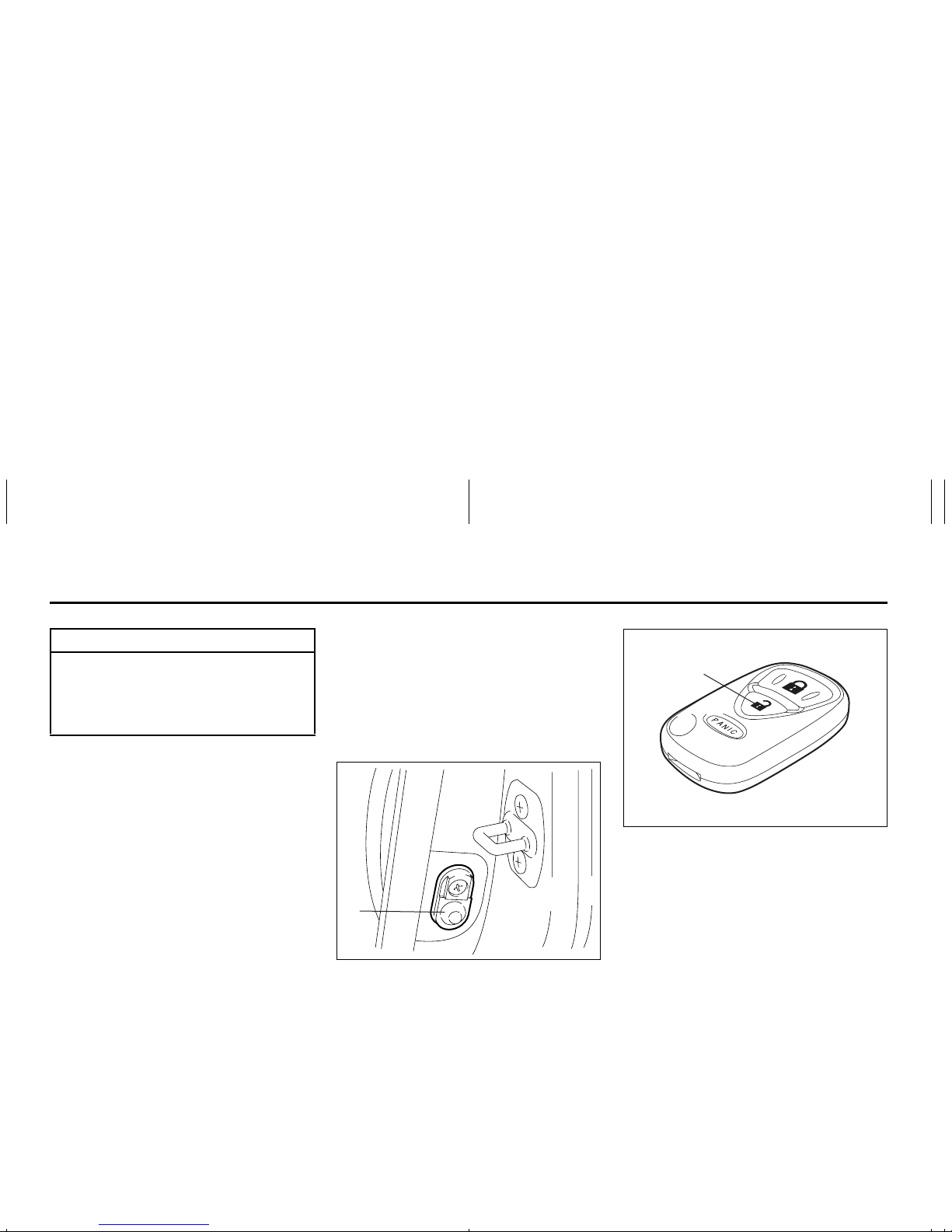
4) Push and release the driver’s door
switch (1) 3 times, insert the key, and
turn the ignition switch to the “ON” position within 20 seconds.
5) Turn the ignition switch to the “LOCK”
position and remove the key within 10
seconds. All doors will lock/unlock to
confirm that this procedure has been
properly completed.
52D212
6) Press the “UNLOCK” button (2) on the
transmitter one time within 20 seconds
(after step 5). All the doors will lock/
unlock to confirm that the procedure
has been completed and the transmitter
has been programmed.
7) If you want to program an additional
transmitter, repeat the procedure from
step 1) through step 6).
Make sure that the keyless entry system operates properly by operating
each transmitter.
CAUTION
The transmitter/remote controller is a
sensitive electronic instrument. To
avoid damaging it, do not expose it to
dust or moisture or tamper with internal parts.
(1)
(2)
Door Locks: 3, 5, 8
2-13
BEFORE DRIVING
To change the old transmitter codes in
your vehicle’s memory
If you have lost one of the transmitters, you
should change the transmitter codes in
your vehicle’s memory as soon as possible
for security.
To remove one of the transmitter codes
from your vehicle’s memory, first replace all
three of the transmitter codes in your vehicle’s memory, then program additional
transmitters as follows:
1) Program one of your transmitters three
times, by repeating the programming
procedure shown in this section. This
will replace all the old transmitter codes
in the vehicle’s memory with the code
for the transmitter you are using.
2) If you want to program up to two additional transmitters, repeat the programming procedure shown in this section.
3) Make sure that the keyless entry system operates properly by operating
each transmitter.
1. For USA
This device complies with Part 15 of the
FCC Rules. Operation is subject to the following two conditions:
1) This device may not cause harmful
interference, and
2) This device must accept any interference received, including interference
that may cause undesired operation.
NOTE:
Changes or modifications not expressly
approved by the party responsible for compliance could void the user’s authority to
operate the equipment.
2. For Canada
This device complies with Industry Canada
Standard RSS-210. Operation is subject to
the following two conditions:
1) This device may not cause interference,
and
2) This device must accept any interference, including interference that may
cause undesired operation of the
device.
The term “IC:” before the certification/registration number only signifies that the
Industry Canada technical specifications
were met.
Child Lock System (rear side doors)
64J009
Each of the rear side doors is equipped
with a child lock which can be used to help
prevent unwanted opening of the door from
inside the vehicle. When the lock lever is in
the “LOCK” position (1), the rear side door
can only be opened from outside. When
the lock lever is in the “RELEASE” position
(2), the rear side door can be opened from
inside or outside.
(2)
(1)
Door Locks: 3, 5, 8
Windows: 3, 8
2-14
BEFORE DRIVING
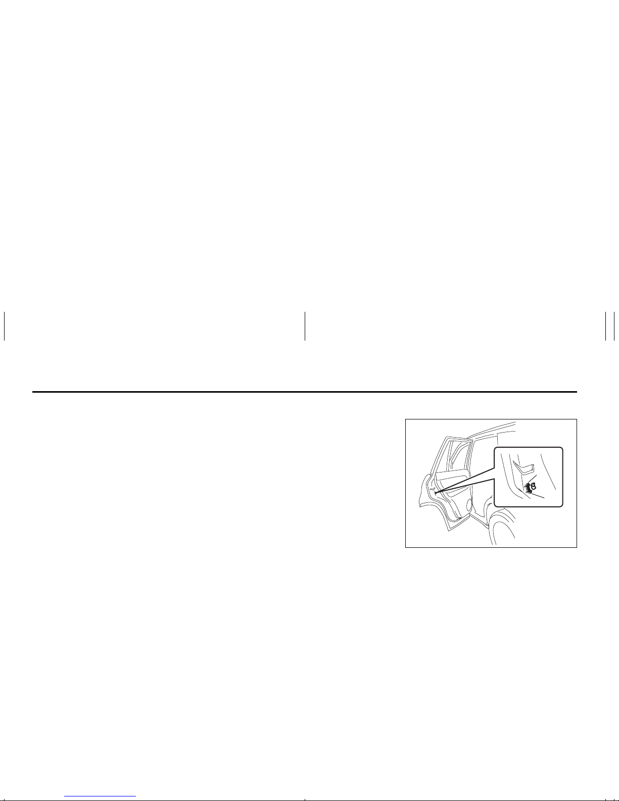
Rear Door
If you can not unlock the rear door due to a
discharged battery or malfunction, follow
the procedures below to unlock the rear
door from inside the vehicle.
1) Remove the luggage compartment
cover.
2) Fold the rear seat forward for easier
access. Refer to the “Folding Rear
Seats” section for details on how to fold
the rear seat forward.
64J202
3) Remove the cap (1) by hand.
4) Break the vinyl using a jack handle or a
flat blade screw driver to access the
emergency lever (2).
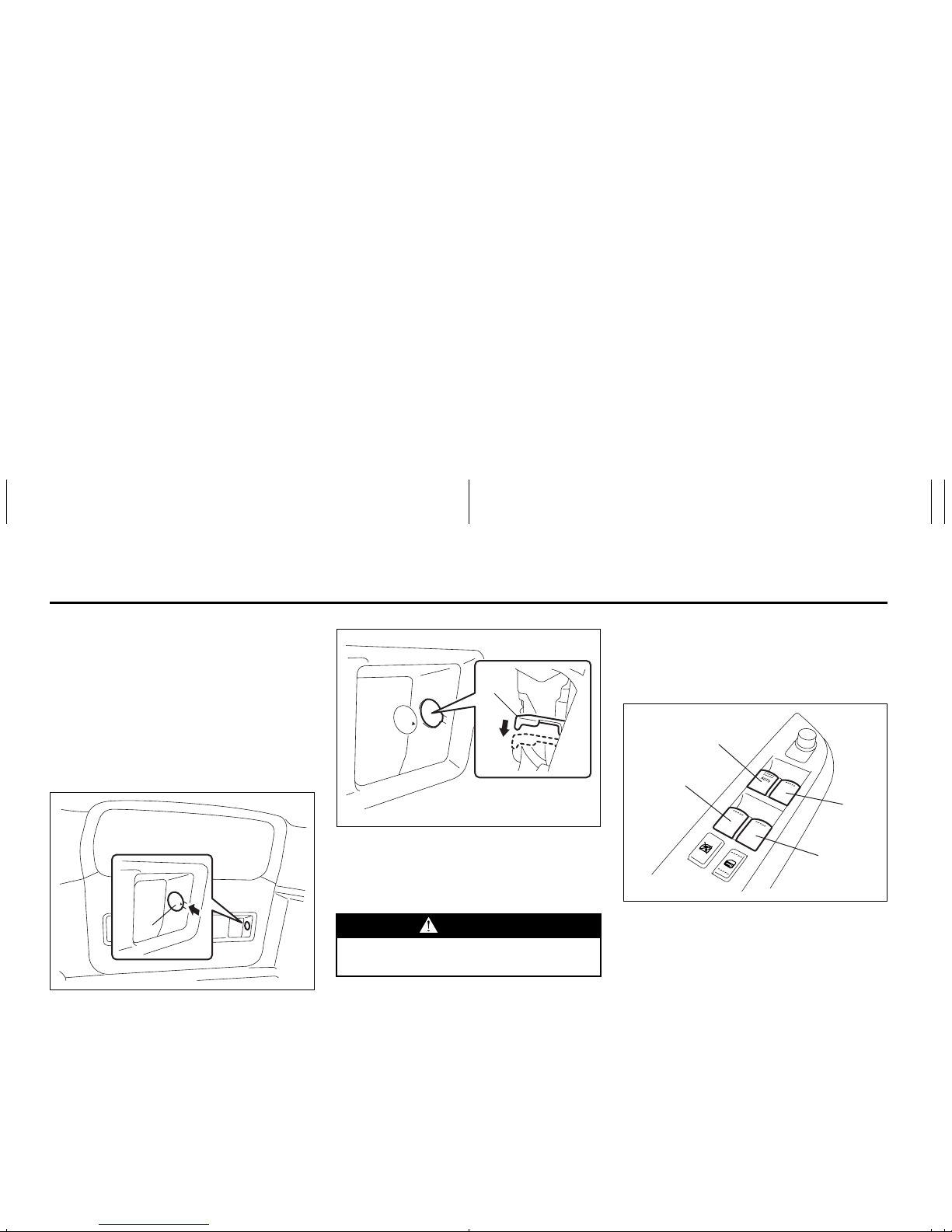
64J203
5) Push down on the emergency lever (2)
using a jack handle or a flat blade screw
driver. To lock the rear door, push up on
the emergency lever (2).
After using the emergency lever, be sure to
see your SUZUKI dealer.
Windows
Power Window Controls
(if equipped)
Driver’s side
64J011
The power windows can only be operated
when the ignition switch is in the “ON” position.
The driver’s door has switches (1), (2), (4),
(5), to operate the driver’s window, the
front passenger’s window, the rear left window and right window, respectively.
(1)
WARNING
To avoid injury, do not use your finger to push the emergency lever.
(2)
(1)
(2)
(4)
(5)
Windows: 3, 8
2-15
BEFORE DRIVING
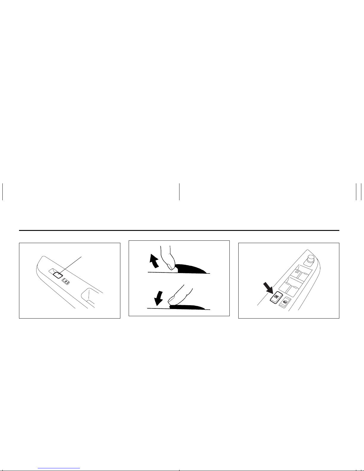
Passenger’s door
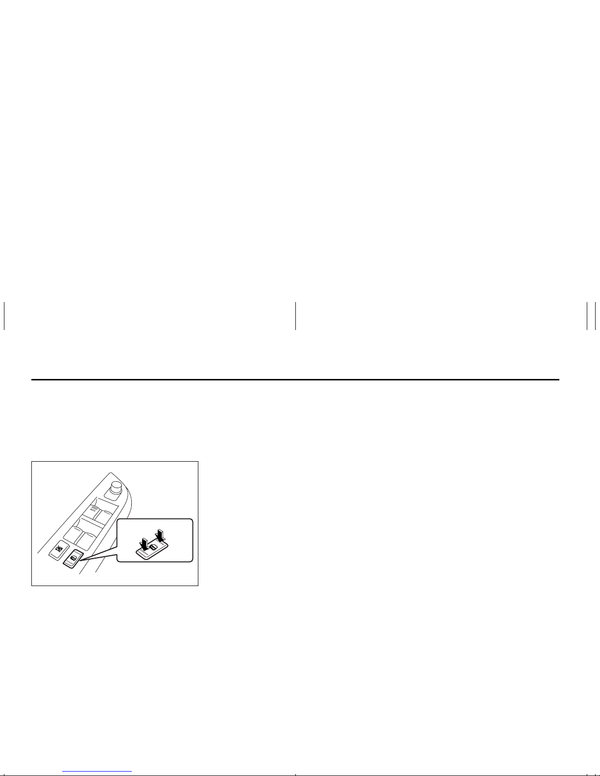
66J164
The passenger’s door has a switch (3) to
operate the passenger’s window.
81A009
To open a window, push the top part of the
switch and to close the window lift up the
top part of the switch.
The driver’s window has an “auto-down”
feature for added convenience (at toll
booths or drive-through restaurants, for
example). This means you can open the
window without holding the window switch
in the “Down” position. Press the driver’s
window switch completely down and
release it. To stop the window before it
reaches the bottom, pull the switch up
briefly.
Lock switch
64J013
The driver’s door also has a lock switch for
the passenger’s window(s). When you
push in the lock switch, the passenger’s
window(s) can not be raised or lowered by
operating either of the switches (2), (3), (4)
or (5). To restore normal operation, release
the lock switch by pushing again.
(3)
EXAMPLE
CLOSE
OPEN
EXAMPLE
Windows: 3, 8
Mirrors: 3, 8
2-16
BEFORE DRIVING
Mirrors
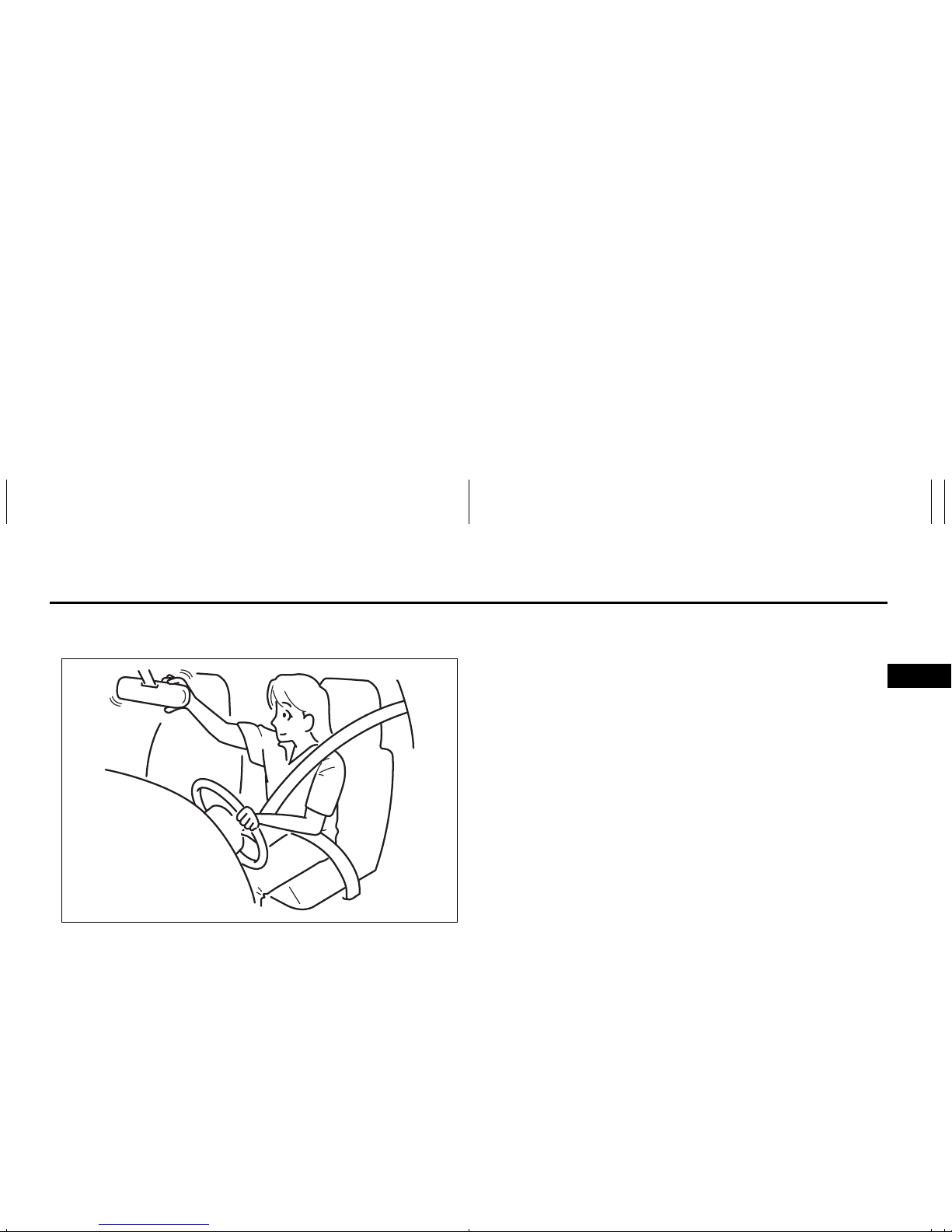
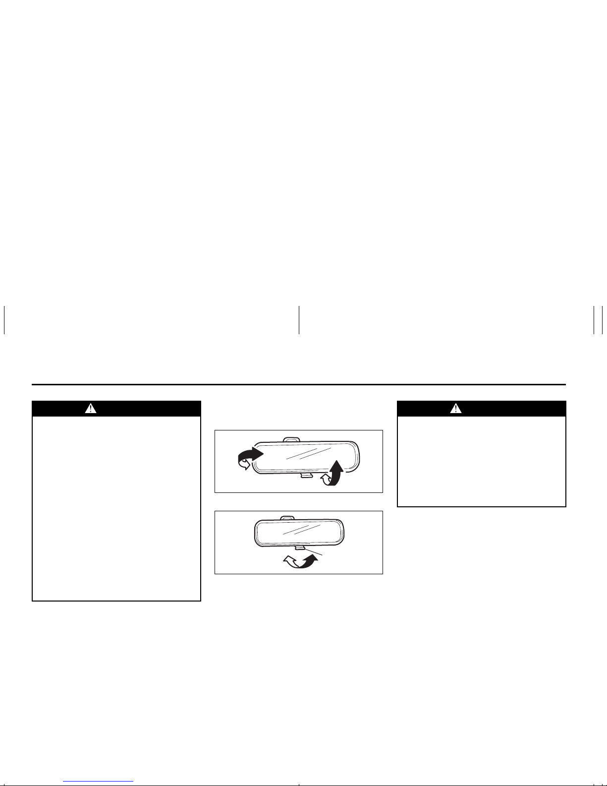
Inside Rearview Mirror
65D410
65D409
You can adjust the inside rearview mirror
by hand so as to see the rear of your ve hicle in the mirror. To adjust the mirror, set
the selector tab (1) to the day position,
then move the mirror up, down or sideways
by hand to obtain the best view.
When driving at night, you can move the
selector tab to the night position to reduce
glare from the headlights of vehicles
behind you.
WARNING
• You should always lock the passenger’s window operation when there
are children in the vehicle. Children
can be seriously injured if they get
part of their body caught by the
window during operation.
• To avoid injuring an occupant by
window entrapment, be sure no
part of the occupant’s body such
as hands or head is in the path of
the electric windows when closing
them.
• Always remove the ignition key
when leaving the vehicle even if a
short time. Also do not leave children alone in a parked vehicle.
Unattended children could use the
electric window switches and get
trapped by the window.
(1)
Day driving Night driving
WARNING
• Always adjust the mirror with the
selector set to the day position.
• Only use the night position if it is
necessary to reduce glare from the
headlights of vehicles behind you.
Be aware that in this position you
may not be able to see some
objects that could be seen in the
day position.
Mirrors: 3, 8
Loading…
Suzuki Grand Vitara (2007)
ENGLISH 14.5 mm
Suzuki Red: Magenta 100%, Yellow 100%Suzuki Blue: Cyan 100%, Magenta 70%takumi Blue: Cyan 100%, Black 85%Black
See page 1-1
SERVICE STATION INFORMATION
Fuel recommendation: Brake and clutch fluid:
Engine oil recommendation:
Tire cold pressure:
Engine oil with “Starburst” symbol
For further details, see “Engine Oil and Filter” in the
“INSPECTION AND MAINTENANCE” section.
DOT3
See the “Tire Information Label” located on the
driver’s door lock pillar.
!»# $%&
Keep With Vehicle At All Times.
Contains Important Information
On Safety, Operation & Maintenance.
2010
Automatic transmission fluid:
SUZUKI ATF 3317 or Mobil ATF 3309
View the manual for the Suzuki Grand Vitara (2007) here, for free. This manual comes under the category cars and has been rated by 71 people with an average of a 8.4.
This manual is available in the following languages: English. Do you have a question about the Suzuki Grand Vitara (2007) or do you need help?
Ask your question here
Product Images (1)
Suzuki Grand Vitara (2007) specifications
Below you will find the product specifications and the manual specifications of the Suzuki Grand Vitara (2007).
The Suzuki Grand Vitara is a compact SUV that was first introduced in 1998. The 2007 model offers a well-rounded package with its blend of style, functionality, and off-road capability.
On the exterior, the Grand Vitara features a rugged yet modern design with prominent wheel arches and a high ground clearance. It is available in both two-door and four-door body styles, providing options for various needs.
Under the hood, the 2007 Grand Vitara comes equipped with a 2.7-liter V6 engine that delivers adequate power for daily driving. It offers a smooth ride and decent fuel efficiency, making it suitable for both city commutes and long trips.
Inside, the Grand Vitara offers a spacious cabin with comfortable seating for up to five passengers. The interior features a straightforward and ergonomic layout, with easy-to-use controls and ample storage space.
In terms of safety, the 2007 Grand Vitara is equipped with standard features including front airbags, antilock brakes, and stability control. It also received favorable crash test ratings, further enhancing its safety reputation.
Additionally, the Grand Vitara offers capable off-road performance due to its four-wheel-drive system and available low-range gearing. This makes it a suitable choice for those seeking adventure and exploring rough terrains.
Overall, the 2007 Suzuki Grand Vitara is a practical and capable SUV that delivers on style, comfort, and off-road performance. It provides a reliable and durable option for individuals in need of a versatile vehicle.
General
| Brand | Suzuki |
| Model | Grand Vitara (2007) |
| Product | car |
| Language | English |
| Filetype | User manual (PDF) |
Frequently Asked Questions
Can’t find the answer to your question in the manual? You may find the answer to your question in the FAQs about the Suzuki Grand Vitara (2007) below.
How do I program a new key fob for my Suzuki Grand Vitara (2007)?
Insert the key into the ignition and turn it from «Off» to «On» eight times within 10 seconds, then leave it in the «On» position. The door locks should cycle to indicate the programming mode. Press any button on the key fob, and the door locks will cycle again to confirm successful programming. Turn the ignition off to exit the programming mode. Repeat the process for each additional key fob you wish to program.
How do I change a flat tire on my Suzuki Grand Vitara (2007)?
First, locate the spare tire, jack, and lug wrench in the trunk. Position the jack under the designated lift points and raise the car until the flat tire is off the ground. Remove the lug nuts using the lug wrench, then carefully take off the flat tire. Fit the spare tire onto the wheel studs and hand-tighten the lug nuts. Lower the car back to the ground and finally, use the lug wrench to fully tighten the lug nuts.
How can I jump-start my Suzuki Grand Vitara (2007)?
To jump-start your car, you’ll need a set of jumper cables and a functioning vehicle. First, connect the positive (red) jumper cable to the positive terminal of the dead battery, then attach the other end of the positive cable to the positive terminal of the charged battery. Next, connect the negative (black) jumper cable to the negative terminal of the charged battery and attach the other end to an unpainted metal surface on your car’s engine block. Start the charged car and allow it to idle for a few minutes before starting your Suzuki Grand Vitara.
How do I check the engine oil level on my Suzuki Grand Vitara (2007)?
Start by parking your car on level ground and ensuring the engine is turned off. Locate the oil dipstick, usually with a yellow handle, and pull it out. Wipe off any oil from the dipstick and reinsert it fully. Pull the dipstick out again and observe the oil level. It should be within the designated range marked on the dipstick. If it’s low, add the appropriate type and amount of oil in small increments, rechecking the level each time.
How can I replace a burnt-out headlight on my Suzuki Grand Vitara (2007)?
Open the hood and locate the back of the headlight assembly. Disconnect the electrical connector by pressing the release tab and pulling it off. Remove the rubber grommet or dust cover if present. Release the retaining clip(s) securing the headlight bulb and carefully remove it from the socket. Install the new headlight bulb, making sure not to touch the glass with bare hands. Secure it with the retaining clip(s), reconnect the electrical connector, and replace any removed covers or grommets.
When does my Suzuki need maintenance?
Regular maintenance is necessary for every car. How often the car needs maintenance and what exactly needs to be done can be found in the maintenance instructions.
For major periodic service, this should generally be done every 2 years or after 30,000 kilometres.
One or more doors won’t open from the inside. Now what?
The lock is most likely set to the child safety lock so it cannot be opened from the inside. How to unset the child safety lock differs per brand and type.
My car radio does not turn on, now what?
If your car radio does not turn on, it will not receive any power. Check that the red wire is connected to the contact power supply and the yellow wire to the constant power supply.
How do I convert miles into kilometres?
1 mile equals 1.609344 kilometers and 1 kilometer equals 0.62137119 miles.
Where can I find the VIN number of my Suzuki?
The location of the VIN number of the car differs per brand and type of car.
The code may be stamped on the frame of the car or mounted on a plate. It is best to consult the manual of the Suzuki Grand Vitara (2007)for the exact location of the VIN number.
When should I change the brake fluid of my Suzuki?
It is recommended to change the brake fluid every two years.
What is the difference between E10 and E5 petrol?
E10 petrol consists of up to ten per cent ethanol while E5 petrol will contain less than five per cent ethanol. As a result, the percentage of E10 petrol is lower than that of E5 petrol, making it less bad for the environment.
What is a VIN number?
The VIN number of a car is an identification number unique to each car. The abbreviation VIN therefore stands for Vehicle Identification Number.
Is the manual of the Suzuki Grand Vitara (2007) available in English?
Yes, the manual of the Suzuki Grand Vitara (2007) is available in English .
Is your question not listed? Ask your question here
-
Suzuki Grand Vitara 2007 Manual (35 pages)
-
Suzuki Grand Vitara 2007 Owner’s manual (211 pages)
Suzuki Grand Vitara 2007 Manuals come in various types, each serving a specific purpose to help users effectively operate and maintain their devices. Each type of Suzuki Grand Vitara 2007 instruction is designed to address specific needs, ensuring users have the necessary information to use, maintain, and repair their devices effectively.
Related Instructions for Suzuki Grand Vitara 2007:
Jimny, SX4 2016, Liana RH418, RA410, 2006 SX4
- Suzuki Jimny
- Suzuki SX4 2016
- Suzuki Liana RH418
- Suzuki RA410
- Suzuki 2006 SX4
- Suzuki CELERIO Series
- Suzuki CIAZ
- Suzuki 2000 Grand Vitara SQ625
- Suzuki Swift 2015
- Suzuki VITARA 1993
- Suzuki Swift Sport 2004
- Suzuki GRAND VITARA JB416
Automobile Devices by Other Brands:
| Brand | Device Model | Type of Document | Pages | Size | Views | Downloads | Updated |
|---|---|---|---|---|---|---|---|
| Acura |
RLX 2019 |
Acura RLX 2019 Manual |
9 | 986 | 217 | 03-09-2024 | |
| Craftsman |
917.372301 |
Craftsman 917.372301 Owner’s manual |
28 | 1.81 Mb | 419 | 76 | 20-11-2024 |
| Hyundai |
2012 Santa Fe Sport |
Hyundai 2012 Santa Fe Sport Quick reference manual |
21 | 1118 | 280 | 20-09-2024 | |
| Cadillac |
2011 Escalade Hybrid |
Cadillac 2011 Escalade Hybrid Manual |
94 | 319 | 71 | 26-10-2024 | |
| Volvo |
S60 — ANNEXE 931 |
Volvo S60 — ANNEXE 931 Owner’s manual |
438 | 12.59 Mb | 253 | 54 | 16-11-2024 |
Categories:
Electronic Keyboard
Security System
Musical Instrument
Automobile
Automobile Accessories
Accessories For Music Instruments
-
Страница 1
Part No. 99011-66J21-03E June, 2006 O WNER’S MANU AL 99011-66J21-03E GRAND VITARA Printed in Japan See page 1-1 12.5 mm Keep With Vehicle At All Times. Contains Important Information On Safety, Operation & Maintenance. SERVICE STATION INFORMATION Fuel recommendation: Brake and clutch fluid: Engine oil recommendation: Automatic transmission fl[…]
-
Страница 2
66J21-03E Prepared by June, 2006 Part No. 99011-66J21-03E Printed in Japan TP286[…]
-
Страница 3
66J21-03E This owner’s manual applie s to the GRAND VITARA series: 66J001 NOTE: The illustrated model is one of the GRAND VITARA series. © COPYRIGHT SUZUKI MOTOR CORPORATION 2006[…]
-
Страница 4
66J21-03E INTRODUCTION Thank you for choosing SUZUKI and welcome to our growing family. Your choice was a wise one; SUZUKI prod ucts are a great value that will give you years of drivi ng pleasure. This Owner’s Manual was p repared to help you have a safe, enjo yabl e, and trouble -free experience with your SUZUKI. In it you wi ll learn about the[…]
-
Страница 5
66J21-03E SERVICE STATION GUIDE 1. Fuel (see section 1) 2. Engine hood (see section 5) 3. Tire changing tools (see section 5) 4. Engine oil dipstick <Yellow> (see section 9) 5. Automatic transmission fluid dipstick <Red> (see sectio n 9) 6. Engine coolant (see section 9) 7. Windshield washer fluid (see section 9) 8. Battery (see section[…]
-
Страница 6
66J21-03E TABLE OF CONTENTS California Proposition 65 Warning WARNING Engine exhaus t, some of it s constitu- ents, and certai n product compo- nents contain or emit chemicals known to the State of California to cause cancer and birth defects or other reproductive harm. FUEL RECOM MENDATION 1 BEFORE D RIV ING 2 STEERI NG COL UMN CONTROLS 3 INSTRUME[…]
-
Страница 7
66J21-03E LOCATION OF WARNING MESSAGES Read and follow all of the warnings (lab els etc.) on your vehicle. Make sure you understand all of th em. Keep them on the vehicle. Do not remo ve the messages for any reason. If a label comes off or the messages become difficult to be read, have it correcte d by your SUZUKI dealer. 1. Air bag warning l abels[…]
-
Страница 8
0-1 66J21-03E FOREWORD Your SUZUKI multip urpose vehi cle is designed and built to be capa ble of per- forming both on pavement and off road. You should therefore remember that your vehicle is distinctly different from ordinary passenger cars in hand ling as well as in structure. As with ot her vehicles of this type, failure to operate this vehicle[…]
-
Страница 9
0-2 66J21-03E If you purchased your SUZUKI in Canada please cont act the Suzuki Canada Cus- tomer Relations Department by telephone at 1-905-889-2677 exten sion 2254 or in writin g at: Suzuki Canada Inc. Customer Rel ations 100 East Beaver Cr eek Road Richmond Hill, On L4B 1J6 In the event you require assistance related to your SUZUKI, while tempor[…]
-
Страница 10
0-3 66J21-03E MODIFICATION WARNING LEAK DETECTION PUMP NOTE: Your vehicle has a pump to regularly check the vehicle’s evaporative e mission control system for leaks. This check is performed approximately five hours after th e engine is turned off. Duri ng this leak check, you may hear a sound coming from the vehicle for several minutes. This soun[…]
-
Страница 11
0-4 66J21-03E MEMO[…]
-
Страница 12
FUEL RECOM MENDATION 1 66J21-03E 65D394 FUEL RECOMMENDATION Fuel Recommendation …………… ……………………. ……………. 1-1[…]
-
Страница 13
1-1 FUEL RE COMMENDATI ON 66J21-03E Fuel Recommendation 60A004 Your vehicle requires re gular unleaded gasoline with a minimum rating o f 87 pump octane ((R + M)/2 method). In some areas, the only fuels th at are available are oxy- genated fuel s. Oxygenated fuels whic h meet the mini- mum octane requireme nt and the require- ments described below […]
-
Страница 14
BEFORE D RI VING 2 66J21-03E 60G404 BEFORE DRIVING Keys ………….. …………………. ……………………. ………………….. .. 2-1 Spare Tire Nut Lo ck (if equipped) ……………. …………………. 2-1 Door Locks …………. …………………. …………………….. …………. 2-2 Windows …… …………[…]
-
Страница 15
2-1 BEFORE DRIVING 66J21-03E Keys 54G489 Your vehicle comes with a pair of ide ntical keys. Keep the spare key in a safe place. One key can open all of the locks on the vehicle. The key identification number i s stamped on a metal tag pr ovided with the keys. Keep the tag in a safe place. If you lose your keys, you will need this number to have new[…]
-
Страница 16
2-2 BEFORE D RI VING 66J21-03E Door Locks Side Door Locks 60A009 To lock a front door from outside the vehi- cle: • Insert the key and turn the top of the key toward the front of the vehicle, or • Turn the lock knob forward and close the door. To unlock a front door from outside the vehicle, insert the key and turn the top of the key toward the[…]
-
Страница 17
2-3 BEFORE DRIVING 66J21-03E Driver’s side 64J004 Front passenger’s side 66J012 (when using the power door l ocking switch) To lock or unlock all the doors simulta- neously, depress the front or rear of the switch respectively. NOTE: • If your vehicle is equ ipped with the key- less entry system, you can also lock or unlock all doors by ope r[…]
-
Страница 18
2-4 BEFORE D RI VING 66J21-03E • You can lock or unlock the doors by pushing the re quest switch on the door handle. For details, refer to the expla na- tion in this section. • You can start the engine w ithout using an ignition key. For details, refer to “Igni- tion Switch” in the “STEER ING COL- UMN CONTROLS” section and “Starting t[…]
-
Страница 19
2-5 BEFORE DRIVING 66J21-03E Keyless unlocking/ locking using the request switches 64J006 When the remote control ler is within the operating range describ ed in this section, you can lock or unl ock the doors by push- ing the request switch (1) on the door han- dle of the driver’s door, front passen ger’s door or rear door. To lock all doors w[…]
-
Страница 20
2-6 BEFORE D RI VING 66J21-03E • If a spare remote controller is in the vehi- cle, the request sw itches may not oper- ate normally. • The remote controller will only operate a request switch if it i s within the switch’s operating range. For example, if the remote controller is within the operating range of the driver’s door request switch[…]
-
Страница 21
2-7 BEFORE DRIVING 66J21-03E Reminder function 66J022 If the remote controller is n ot in the vehicle under the followi ng conditions, a buzzer sounds intermittently for abou t 2 seconds and the keyless start system indicator light on the instru ment cluster blinks in red: • When the vehicle speed is over 10 km/h (6 mph). • When one or more doo[…]
-
Страница 22
2-8 BEFORE D RI VING 66J21-03E 66J017 2) Repla ce the battery (1) (Lit hium disc type CR2032 or equivale nt) so its + ter- minal faces the bottom of the case as shown in the illustration. 3) Close the re mote controller firmly. 4) Make sure the door lo cks can be oper- ated with the remote controller. 5) Dispose of the used battery properly accordi[…]
-
Страница 23
2-9 BEFORE DRIVING 66J21-03E To program a new remote controller 1) Close all the doors of the vehicle . 2) Sit in the driver’s seat and confirm that the driver’s door is unlocked. 3) Insert the key into the ignition switch. 4) Complete steps 1 through 6 describ ed below within 25 seconds after step 3). 64J004 1. Push the power door locking swit[…]
-
Страница 24
2-10 BEFORE D RI VING 66J21-03E less entry system o perate properly by operating each remote controller. 1. For US A This device complies with Part 15 of the FCC Rules. Operation is subject to the fol- lowing two conditions: 1) This device may not cause harmful interference, and 2) This device must accept any inte rfer- ence received, inclu ding in[…]
-
Страница 25
2-11 BEFORE DRIVING 66J21-03E “PANIC” button (3) function This function is to get the attention of oth- ers. Press the “PANIC” button (3) for more than 1 second. The headlights and tai llights will blink for about 30 seconds. Also, the horn will sound intermittently for about 30 sec- onds at the same time. To cancel the “PANIC” mode, pr[…]
-
Страница 26
2-12 BEFORE D RI VING 66J21-03E Programming/removi ng a transmitter code yourself Your new vehicle was originally equ ipped with two transmitters. If you have lost one of the transmitters, you should change th e transmitter code in your vehicle’s memory as soon as possible for security. If you pu rchase additional trans- mitters, the new transmit[…]
-
Страница 27
2-13 BEFORE DRIVING 66J21-03E To change the old transmitter codes in your vehic le’s memory If you have lost one of the transmitters, you should change the transmitter codes in your vehicle’s memory as soon as possible for security. To remove one of the transmitter codes from your vehicle’s memory, first replace all three of the transmitter c[…]
-
Страница 28
2-14 BEFORE D RI VING 66J21-03E Rear Door If you can not unl ock the rear door due to a discharged battery or ma lfunction, follow the procedures be low to unlock the rear door from inside the vehi cle. 1) Remove the lugg age compartment cover. 2) Fold the rear seat forward for easier access. Refer to the “Folding Rear Seats” section for detail[…]
-
Страница 29
2-15 BEFORE DRIVING 66J21-03E Passenger’s door 66J164 The passenger’s door has a switch (3) to operate the passenger’s window. 81A009 To open a window, push the top part of the switch and to close the window li ft up the top part of the switch. The driver’s window has an “auto-down” feature for added conve nience (at toll booths or driv[…]
-
Страница 30
2-16 BEFORE D RI VING 66J21-03E Mirrors Inside Rearview Mirror 65D410 65D409 You can adjust the inside rearview mirror by hand so as to see the rear of your vehi- cle in the mirror. To adjust the mirror, set the selector tab (1) to the day position, then move the mirror up, down or sid eways by hand to obtain the best view. When driving at night, y[…]
-
Страница 31
2-17 BEFORE DRIVING 66J21-03E Outside Rearview Mirrors 64J014 Adjust the outside rearview mirrors so you can just see the side of your vehicle in the mirrors. The passenger’s side mi rror is a convex (curved surface) mirror. Objects seen in this mirror will look small er and appear far- ther away than when seen in a flat mirror. Power Mirror Cont[…]
-
Страница 32
2-18 BEFORE D RI VING 66J21-03E Adjusting Seat Position Front seat 64J016 The adjustment lever for each front seat is located under the front of the seat. To adjust the seat position, pull up on the adjustment lever and slide the se at forward or rearward. After adjustment, try to move the seat forward and rearward to e nsure that it is securely la[…]
-
Страница 33
2-19 BEFORE DRIVING 66J21-03E Rear seat 64J019 To adjust the seatba ck angle of the rear seats: 1) Pull up the lever on the top of a split folding seat. 2) Move the seatback to one of the lock positions. The numbe r of the lock posi- tions depends on the vehicle specifica- tion. 3) Release the lever to lock the seatback in position. After adjustmen[…]
-
Страница 34
2-20 BEFORE D RI VING 66J21-03E 1) Insert a sharp-pointed tool into the small hole (2). Push the tip into the hole (2) and hold it while pushing in the release knob (1). 2) Pull the head restraint all the way out while pushing the relea se knob (1) and holding the tip in the hole (2). NOTE: It may be necessary to recline the seat- back to provide e[…]
-
Страница 35
2-21 BEFORE DRIVING 66J21-03E 65D606 65D201 65D199 WARNING • Never allow persons to ride in the cargo area of a vehi cle. In the event of an accident, there is a much greater risk of injury for persons who are not riding in a seat with their seat belt securely fastened. • Seat belts should always be adjusted as follows: – the lap porti on of […]
-
Страница 36
2-22 BEFORE D RI VING 66J21-03E Lap-Shoulder Belt Emergency Locki ng Retractor (ELR) The lap-shoulder seat belt ha s an emer- gency locking retractor (ELR), which is designed to lock the seat be lt only during a sudden stop or i mpact. It also may lock if you pull the belt ac ross your body very quickly. If this happens, let the belt go back to unl[…]
-
Страница 37
2-23 BEFORE DRIVING 66J21-03E Safety reminder 60A038 60A040 To reduce the risk of sliding under the belt during a collision, positio n the lap portion of the belt acro ss your lap as low on your hips as possible and a djust it to a snug fit by pulling the should er portion of the belt upward through the la tch plate. The length of the diagonal shou[…]
-
Страница 38
2-24 BEFORE D RI VING 66J21-03E 52D249 NOTE: The word “CENTER” is molded into the buckle for the rear seat center belt. The buckles are designed so a l atch plate can not be inserted into the wrong buckle. 60A039 To unfasten the belt, push the red “PRESS” button on the buckle and allow the belt to retract. Seat Belt Reminder Driver’s seat[…]
-
Страница 39
2-25 BEFORE DRIVING 66J21-03E When the driver and fron t passenger don’t buckle their seat belts, the driver’s seat belt reminder light in the instrument cluster and the front passenge r’s seat belt reminder light in the center of the in stru- ment panel will come on and a buzzer wi ll sound as a reminder to the driver and fron t passenger to[…]
-
Страница 40
2-26 BEFORE D RI VING 66J21-03E Driver’s seat belt r eminder If the driver’s seat belt remains unbu ckled with the igni tion key in the “ON” position, the driver’s seat belt reminder works as fol- lows: 1) The driver’s seat belt reminder light wi ll come on for about 20 seconds when the ignition key is turned to the “ON” position th[…]
-
Страница 41
[…]
-
Страница 42
2-28 BEFORE D RI VING 66J21-03E Infant restraint — rear seat on ly 65D584 Booster seat 65D203 SUZUKI highly recommends that you use a child restrain t system to rest rain infants and small children. Many different typ es of child restraint systems are available; make sure that the restra int system y o u select meets Federal Motor Vehicle Safety St[…]
-
Страница 43
2-29 BEFORE DRIVING 66J21-03E 65D607 65D608 65D609 Installation with Lap-Shoulder Seat Belts (Child Restraint with No Top Strap) 83E031 Install your child re straint system accord- ing to the instructions provid ed by the child restraint system manufa cturer. If you install the child restraint system in the front seat, be sure to slide the seat to […]
-
Страница 44
2-30 BEFORE D RI VING 66J21-03E 83E035 1) Pull all of the remaining webb ing out of the retractor. You will hear a click, which means that the emergency locking retractor (ELR) has converted to func- tion as an automatic locking retractor (ALR). 83E032 2) Allow the extra webbing to retract, and pull the webbing toward the retractor to take up any s[…]
-
Страница 45
2-31 BEFORE DRIVING 66J21-03E 65D234 65D235 4) Try moving the child restraint system in all directions, to make sure it is securely installed. If you need to tig hten the belt, pull more webbing toward the retractor. To revert from ALR to ELR 65D267 When you unbuckle the seat belt a nd allow it to retract to a certain length, the retractor will aut[…]
-
Страница 46
2-32 BEFORE D RI VING 66J21-03E and Tethers for Children.) The anch ors are located where the rear o f the seat cushion meets the bottom of the seatback. Install a LATCH-type child restraint system according to th e instructions provided by the child restraint system manufacturer. After installing the ch ild restraint system, try moving it in all d[…]
-
Страница 47
2-33 BEFORE DRIVING 66J21-03E 65D342 5) Make sure the child restraint is securely fastened by trying to move the child restraint system in all directions, espe- cially forward. If your LATCH restraint has rigid lower con- necting bars, these general instructi ons apply: 1) If possible , fold the seatback rearward for easier installation. 2) Place t[…]
-
Страница 48
2-34 BEFORE D RI VING 66J21-03E 54G185 5) Grasp the front of the child restraint an d push the child rest raint forcefully to latch the connecting bars. Make sure they are securely latched by trying to move the child restraint system in all directions, especial ly forward. 6) Return the seatback if folded. Attach the top tether str ap, if applicabl[…]
-
Страница 49
2-35 BEFORE DRIVING 66J21-03E how to raise or lower the head restraint.) 5) Make sure that cargo does not interfere with routing of the top strap. Seat Be lt Extender 65D613 (1) Center of body (2) Less than 152 mm (6 inches) (3) Open end of exten der buckle If a seat belt cannot be fastened securely because it is not long e nough, see your authoriz[…]
-
Страница 50
2-36 BEFORE D RI VING 66J21-03E Seat Belt Pretension er System (for front seat belt only) 52D011 Your vehicle is equipped with a seat belt pretensioner system at the front seating positions. You can use the pretensioner seat belts in the same manner as ordinary seat belts. The seat belt pret ensioner system works with the SUPPLEMENTAL RESTRAINT SYS[…]
-
Страница 51
2-37 BEFORE DRIVING 66J21-03E tions and precautions about the seat belts in this “Seat Belts and Child Restraint Sys- tems” section for details on prope r seat and seat belt adjustments. Please note that the pretensioners alo ng with the front air bags will activate only in severe frontal collision s. They are no t designed to activate in rear […]
-
Страница 52
2-38 BEFORE D RI VING 66J21-03E 66J126 1 2 8 3 5 8 9 3 4 7 10 10 6 66J132 Your vehicle is equipped wi th a Supple- mental Rest raint System consisting of the following components i n addition to a lap- shoulder belt at each front seating position. 1. Driver’s front air bag 2. Front passenger’s front air bag 3. Seat belt pretensione rs 4. Air ba[…]
-
Страница 53
2-39 BEFORE DRIVING 66J21-03E 63J030 If the “AIR BAG” light on the instrument cluster does not b link when the igni tion switch is first turned to the “ON” position, or the “AIR BAG” light stays on, or comes on while driving, the air bag system (or the seat belt pretensi oner system) may not work properly. Have the ai r bag system inspe[…]
-
Страница 54
2-40 BEFORE D RI VING 66J21-03E Front air bags will no t inflate 65D236 Front air bags will pro b ably not inflate 65D237 They are not designed to in flate in rear impacts, si de impact s, rollovers or minor frontal collisions, since they would offer no protection i n those types of accidents. Remember, since air bags deplo y only one time during a[…]
-
Страница 55
2-41 BEFORE DRIVING 66J21-03E side air bag cover to identify th e location of the side air bags. 64J034 Side curtain air bags are located i n the roof lining. The words “SRS AIRBAG” are molded into the pillar to identi fy the loca- tion of the side curtain air bags. Side collision range 64J036 Side air bags and side curtain air bags will not in[…]
-
Страница 56
2-42 BEFORE D RI VING 66J21-03E Front Passenger Sensing System The front passenger sensing system will turn off the front passeng er’s front air bag and seat belt pretensioner unde r certain conditions. This system works using a sen- sor mat that is part of the front passenger’s seat. The front passeng er sensing system is designed to detect wh[…]
-
Страница 57
2-43 BEFORE DRIVING 66J21-03E bag will not deploy and th e seat belt pre- tensioner will not operate. If you have secured a chil d in the front pas- senger seat in a fo rward-facing child restraint system or booster seat and the “PASS AIR BAG OFF” indicator light is not on, turn the vehicle off, remove th e child restraint or booster seat from […]
-
Страница 58
2-44 BEFORE D RI VING 66J21-03E When using a seat belt extender, fo llow the instructions in the “Seat Belt Extender” section. How the System Works In a frontal collision , the crash sensors will detect rapid decel eration and send a signal to the controller. If the controller jud ges that the deceleration re presents a severe frontal crash, th[…]
-
Страница 59
2-45 BEFORE DRIVING 66J21-03E the facial area ag ainst a front air bag. Also, upon inflati on, a loud noise will occur and some powder and smoke will be released . These conditions are not harmful and do not indicate a fire in the car. Be aware, however, that some air bag components may be hot for a while after inflation. A seat belt helps keep you[…]
-
Страница 60
2-46 BEFORE D RI VING 66J21-03E Note that e ven though your vehicl e may be moderately damaged in a collisi on, the col- lision may not have been severe enough to trigger the front, side, or side curtain air bags to inflate. If your car sustains ANY front-end or side damage, h ave the air bag system inspected by an authorized SUZUKI dealer to ensur[…]
-
Страница 61
2-47 BEFORE DRIVING 66J21-03E MEMO[…]
-
Страница 62
INSTRUMENT PANE L 4 66J21-03E 60G406 INSTRUMENT PANEL Instrument Panel ……. ……………………. ……………………. …….. 4-1 Instrument Cluster …. ……………………. ……………………. …….. 4-2 Warning and Ind icator Lights ….. …………………….. …………. 4-3 A/T Selector Position Indicator (if […]
-
Страница 63
4-1 I NSTRUMENT P ANEL 66J21-03E Instrument Panel 1. Instrument cluster 2. Ignition switch 3. Lighting switch/Turn signal and dim- mer switch 4. Windshield wiper and washe r switch/ Rear window wiper an d washer switch 5. Hazard warning switch 6. Other switches (if equipped) 7. Heater control pa nel/Climate control panel 8. Audio system (if equippe[…]
-
Страница 64
4-2 INSTRUMENT PANE L 66J21-03E Instrument Cluster 1. Speedometer 2. Odometer/Tripmeter 3. Odomete r/Tripmeter selector and meter illumination cancel knob 4. Tachometer 5. Fuel gauge 6. Temperature gauge 7. Warning and indicator lights 66J212 4 72 7 36 15 EXAMPLE Instrum ent C l uste r: 8[…]
-
Страница 65
4-3 I NSTRUMENT P ANEL 66J21-03E Warning and Indicator Lights Front Passenger’s Seat Belt Reminder Light 66J030 The front passenger’s seat belt reminder light is located in the center o f the instru- ment panel. If there is a passenger in the front seat and the front passenge r’s seat belt is unbuckled about 10 seconds after the ignition swit[…]
-
Страница 66
4-4 INSTRUMENT PANE L 66J21-03E inflation pressure as specified i n the vehi- cle placard a nd owner’s manual. The low tire pressure warnin g light is also used to inform you of a TPMS ma lfunction. When the system detects a malfunction, this light will flash for appro ximately one minute and then remain co ntinuously illu- minated. This sequence[…]
-
Страница 67
4-5 I NSTRUMENT P ANEL 66J21-03E Brake System Warning Light 65D477 This light comes on bri efly when the igni- tion switch is turned to the “ON” position. The light also come s on under the fol low- ing conditions: 1) when the p arking brake is engaged, and 2) when the fluid in the brake fluid reservoir fall s below the speci- fied level. The l[…]
-
Страница 68
4-6 INSTRUMENT PANE L 66J21-03E SLIP Indicator Light 66J033 ESP ® is a registered trademark o f DaimlerChrysler AG. This light blinks 5 times per second when one of the ESP ® systems other than ABS is activated. If this light blinks, drive care- fully. When the ignition sw itch is turned to the “ON” position, the l ight comes on briefly so yo[…]
-
Страница 69
4-7 I NSTRUMENT P ANEL 66J21-03E systems (other than ABS) will turn on automatically and the light will go out. For details of the ESP ® systems, refer to “Electronic Stability Program (ESP ® )” in the “OPERATING YOUR VEHICLE” sec- tion. Oil Pressure Light 50G051 This light comes on when the igniti on switch is turned to the “ON” posi[…]
-
Страница 70
4-8 INSTRUMENT PANE L 66J21-03E “AIR BAG” Light 63J030 This light monitors inflators, crash sen sors, seat belt pretensioners, the fron t passen- ger sensing system, and corresponding electrical circuits. This light blinks for several seconds when the ignition switch is turned to the “ON” position so you can check if the light is working. T[…]
-
Страница 71
4-9 I NSTRUMENT P ANEL 66J21-03E Low Fuel Warning Light 54G343 If this light comes on, fill the fuel tank immediately. NOTE: The activation point of this light varies depending on road conditions (for exam- ple, slope or curve ) and driving cond itions because of fuel moving in the tank. Open Door Warning Light 54G391 This light remains on until al[…]
-
Страница 72
4-10 INSTRUMENT PANE L 66J21-03E Turn Signal Indicators 50G055 When you turn on the left or right turn sig- nals, the corresponding green arrow o n the instrument panel will flash along with the respective turn signal lights. When you turn on the haza rd warning switch, both arrows will flash along with all of the turn signal ligh ts. High Beam Ind[…]
-
Страница 73
4-11 I NSTRUMENT P ANEL 66J21-03E (1): Neutral (2): 4-wheel drive hi gh range center differ- ential lock mode (2) & (3): 4-wheel drive low range center differenti al lock mode No indicators: 4-wheel drive high ran ge mode For details, refer to “U sing the Transfer Switch” in the “OPER ATING YOUR VEHI- CLE” section. If the indicators (al[…]
-
Страница 74
4-12 INSTRUMENT PANE L 66J21-03E 64J049 When the ignition sw itch is turned to the “ON” position, the di splay shows the odometer or trip meter. The display shows thre e types of indica- tion; odometer, trip meter A and trip meter B. Push the selector knob (3) quickly to switch the indication among the three. You can use the two trip meters (A […]
-
Страница 75
4-13 I NSTRUMENT P ANEL 66J21-03E meter brightness becomes di mmest and the other instrument panel li ghts are turned off. To brighten the instrument panel lights, turn the knob (3) clockwise. To cancel the autom atic dimming feature and maintain full brightness, turn th e knob (3) clockwise to position (5). Tachometer 64J051 The tachometer indicat[…]
-
Страница 76
4-14 INSTRUMENT PANE L 66J21-03E tions (for example, sl ope or curve) and driving condi tions because of fuel moving in the tank. The mark (2) indicates that the fuel filler door is locate d on the right si de of the vehi- cle. Temperature Gauge 64J053 When the igniti on switch is in the “ON” position, this gauge indicates the engine coolant te[…]
-
Страница 77
4-15 I NSTRUMENT P ANEL 66J21-03E Hazard Warning Switch 64J054 Push in the hazard warning switch to acti- vate the hazard warni ng lights. All four turn signal lights and both turn signal in dicators will flash si multaneously. To turn off the lights, push the switch again. Use the hazard warning lights to warn other traffic during emergency parkin[…]
-
Страница 78
4-16 INSTRUMENT PANE L 66J21-03E Front Fog Light Switch (if equipped) 64J058 The front fog light comes on when the fog light switch is pushed in with: • the lighting switch turn ed to the third position and the beams set to the l ow beam position, or • the auto-on headligh t system on and the beams set to the low beam position. “ESP OFF” Sw[…]
-
Страница 79
4-17 I NSTRUMENT P ANEL 66J21-03E Transfer Switch (if equipped) 66J168 The transfer switch is located on the center of the instrument panel. For details on how to use this switch, refer to “Using the Transfer Switch” in the “OPERATING YOUR VEHICLE” section. Glove Box 64J065 To open the glove b ox, pull the latch leve r. To close it, push th[…]
-
Страница 80
4-18 INSTRUMENT PANE L 66J21-03E quickly, hold in the “H” button (4) for about 1 second and continu e holding. • To set the minute display, push the “M” button (5) repea tedly to advance the minute display. To a dvance the minute display quickly, hold in the “M” button (5) for about 1 second and continue holding . Thermometer (2) The […]
-
Страница 81
4-19 I NSTRUMENT P ANEL 66J21-03E Instantaneous fuel consumption (a) If you selected instan taneous fuel con- sumption th e last time you drove the vehi- cle, the display indi cates “—.-” when the ignition switch is turned to the “ACC” or “ON” position. Unless the ve hicle is mov- ing, the display will indicate “—.-”. Average fuel[…]
-
Страница 82
4-20 INSTRUMENT PANE L 66J21-03E Driving ra nge 66J202 3) Push the “DISP” bu tton (6) quickly to change the display as shown i n the above illustrations. 4) Push the “DISP” button (6) for more than 2 seconds, and the unit display wi ll stop blinking and the display will stay on. If you don’t push the “DISP” button (6) within about 8 s[…]
-
Страница 83
4-21 I NSTRUMENT P ANEL 66J21-03E Air Outlet (front) 64J066 1. Windshield defro ster outlet 2. Side defroste r outlet 3. Side outlet 4. Center outl et 5. Floor outlet 1 1 2 2 3 3 5 5 5 5 4 EXAMPLE Center ou tlet 64J199 Close Open EXAMPLE Heati ng and Air Condit ioni ng System: 4[…]
-
Страница 84
4-22 INSTRUMENT PANE L 66J21-03E Side outlet 63J045 When “Open”, air comes out from the si de outlets regardless of the air flow selector position. Heating System Description of Controls 64J067 Temperatu re selector (1) This is used to select th e temperature by turning the selector. Blower speed selector /Air intake selec- tor (2) This is used[…]
-
Страница 85
4-23 I NSTRUMENT P ANEL 66J21-03E you should occasionally se lect “FRESH AIR”. Air flow selector (3) 64J068 This is used to select one of the functions described below by p u shing the selector. The indicator light of the selected mode will come on. Ventilation (c) 64J069 Temperature-controlled air comes out o f the center and side air ou tlets[…]
-
Страница 86
4-24 INSTRUMENT PANE L 66J21-03E System Operating Instructions Natural venti lation Select “VENTILATION” and “FRESH AIR”, the temperature selector to the desired temperature position, and the blower speed selector to “OFF”. Fresh air will flow through the vehicle during driving . Forced ventilation The control settings are the same as f[…]
-
Страница 87
4-25 I NSTRUMENT P ANEL 66J21-03E Automatic Heating and Air Conditioning System (Climate Control) Description of Controls 66J042 Temperatur e selector/Air conditi oning switch (1) 66J043 This is used to select th e temperature by turning the selector. Also, this is used to turn on and off the air conditioning system by pushing the switch. To turn o[…]
-
Страница 88
4-26 INSTRUMENT PANE L 66J21-03E 64J134 RECIRCULATED AIR When this mode i s selected, the indicator light (a) will co me on, outside ai r is shut out and inside air is recirculated. This mode is suitable when driving throug h the polluted air such as a tun nel, or attempting to quickly cool down. FRESH AIR When this mode i s selected, the indicator[…]
-
Страница 89
4-27 I NSTRUMENT P ANEL 66J21-03E Heat (e) 64J071 Temperature-controlled air comes out o f the floor outlets an d the side outlets, also comes out of the windshield defroster out- lets and the side defroster outlets sligh tly. Heat & defrost (f) 64J072 Temperature-controlled air comes out o f the floor outlets, the windshield defroster outlets,[…]
-
Страница 90
4-28 INSTRUMENT PANE L 66J21-03E When you turn the air conditionin g switch off, the climate co ntrol system cannot lower the in side temperature b elow outside temperature. To turn the climate control system off, turn the blower speed selector (2) to the “OFF” position. NOTE: • To find your comfortable zone, start with the 25°C (75°F) sett[…]
-
Страница 91
4-29 I NSTRUMENT P ANEL 66J21-03E Maintenance If you do not use the air conditioner for a long period, such as during winter, it may not give the best performance when you start using it again. To he lp maintain opti- mum performance and durability of your air conditioner, it needs to be ru n periodically. Operate the air condi tioner at least once[…]
-
Страница 92
4-30 INSTRUMENT PANE L 66J21-03E Precautions • When the inside of the car is very cold and the player is used soon after switch- ing on the heater, moisture may form on the disc or the opti cal parts of the player and proper playback may n ot be possi- ble. If moisture forms on the disc, wipe it off with a soft cloth. If moisture forms on the opt[…]
-
Страница 93
4-31 I NSTRUMENT P ANEL 66J21-03E 52D348 Never stick labels on the surface of the compact disc or mark the surface with a pencil or pen. 52D349 Do not use any solven ts such as commer- cially available cleaners, anti-static spray, or thinner to clean compact discs. 52D350 Do not use co mpact discs that have large scratches, are misshaped, or cracke[…]
-
Страница 94
4-32 INSTRUMENT PANE L 66J21-03E Basic Operations 66J215 (1) (2) (3) (4) (1) (2) (3) (4) Type 1 AM/FM/XM CD PLAYER WITH CD CHANGER CONTROL Type 2 AM/FM/XM 6-CD PLA YER WITH CD CHANGER CONTROL (1) Power on/off knob Volume control knob (2) Tone/balance/fader contro l knob (3) Preset button 5 (4) Preset button 6 Audio Syst ems:[…]
-
Страница 95
4-33 I NSTRUMENT P ANEL 66J21-03E Turning p ower on/off Press the power on/off knob (1). The unit start s in the func tion mode it was in when the power was turned off last. Adjusting th e volume Turn the volume control knob (1). Turning it clockwise increases the volume; turning it counterclockwise decreases the volume. NOTE: While driving, adjust[…]
-
Страница 96
4-34 INSTRUMENT PANE L 66J21-03E Listening to the Radio 66J216 (1) (4) (6) (2) (3) (5) (1) (4) (6) (2) (3) (5) Type 1 AM/FM/XM CD PLAYER WITH CD CHANGER CONTROL Type 2 AM/FM/XM 6-CD PLA YER WITH CD CHANGER CONTROL Display 66J097 (1) Band switch b utton (FM/AM) (2) Seek up button (3) Seek down button (4) Manual tuning knob (5) Preset buttons (1 to 6[…]
-
Страница 97
4-35 I NSTRUMENT P ANEL 66J21-03E Selecting the reception band Press the band switch button (1). Each time the button is pressed, the recep- tion band is switche d as follows: 66J098 Seek tuning Press the seek up button (2) or th e seek down button (3). The unit stops searchin g for a station at a frequency where a broadcast stati on is available. […]
-
Страница 98
4-36 INSTRUMENT PANE L 66J21-03E Radio Antenna 63J055 The radio antenna on the roof is remov- able. To remove the an tenna, turn it coun- terclockwise. To reinstall the antenna, turn it clockwise firmly by hand. Listening to a CD 52D274 • CDs or CD-ROMs carrying no mark (A) cannot be used. • Some discs previously recorded in CD- RCD-RW format […]
-
Страница 99
4-37 I NSTRUMENT P ANEL 66J21-03E Type 1 AM/FM/XM CD PLAYER WITH CD CHANG ER CONTROL (Built in CD Player) 66J099 (3) (6) (4) (2) (1) (5) Display 66J100 (1) CD insertion slot (2) CD eject button (3) Disc button (CD/AUX) (4) Track up butt on/Fast forward button (5) Track down button/Rewind button (6) Repeat button (RPT) (A) Mode indicato r (B) Track […]
-
Страница 100
4-38 INSTRUMENT PANE L 66J21-03E NOTE: About Single CDs (8 cm C Ds) • No adapter is re quired to play a sing le CD. • A single CD is inse rted from the center of the CD insertion slot. • Since an ejected single CD is not auto- matically reloaded, be sure to remove the ejected singl e CD. Loading a CD Insert a CD in the CD insertion slot (1). […]
-
Страница 101
4-39 I NSTRUMENT P ANEL 66J21-03E Type 2 AM/FM/XM 6-CD PLAYER WITH CD CHAN GER CONTROL (Built-in CD Changer) 66J217 (2) (5) (1) (8) (6) (4) (3) (7) Display 66J102 (1) Load button (LOAD) (2) Disc select buttons (1 to 6) (3) CD insertion slot (4) CD eject button (5) Disc button (CD/AUX) (6) Track up butt on/Fast forward button (7) Track down button/R[…]
-
Страница 102
4-40 INSTRUMENT PANE L 66J21-03E NOTE: About Single CDs (8 cm C Ds) • Since the uni t is not compatibl e with a single CD, do not load it into the unit. • Keep in mind the fact that a single CD cannot be played even using a sing le CD adaptor for the unit. • When a single CD is loaded into the unit accidentally, it will be ejec ted immedi- at[…]
-
Страница 103
4-41 I NSTRUMENT P ANEL 66J21-03E Ejecting all the CDs Press the CD eject button (4) for 2 sec- onds or longer. All the CDs will be e jected from the unit in a sequential manner. • Please prepare a location where removed CDs can be stored. • If you leave the ejected CD withou t removing it, it will be drawn into the unit automatically afte r ab[…]
-
Страница 104
4-42 INSTRUMENT PANE L 66J21-03E Listening to an MP3/WMA Disc 66J218 (1) (2) (3) (4) (1) (2) (5) (3) (4) (5) Type 1 AM/FM/XM CD PLAYER WITH CD CHANGER CONTROL Type 2 AM/FM/XM 6-CD PLA YER WITH CD CHANGER CONTROL Display (Type 1) 66J104 Display (Type 2) 66J105 (1) Sound control knob (2) Repeat button (RPT) (3) Track up butt on/Fast forward button (4[…]
-
Страница 105
4-43 I NSTRUMENT P ANEL 66J21-03E MP3/WMA MODE Selecting a folder Turn the sound control knob (1) to select a folder. Repeat play Press the repeat button (2). Each time the bu tton is pressed, repeat play mode changes as follows: Type 1 66J128 Type 2 66J145 NOTE: This operation should be performed within 2 seconds. To cancel repeat play, press the […]
-
Страница 106
4-44 INSTRUMENT PANE L 66J21-03E Listening to a XM Sate llite Radio (Option) 66J219 (5) (2) (8) (6) (3) (4) (7) (1) (5) (2) (8) (6) (3) (4) (7) (1) Type 1 AM/FM/XM CD PLAYER WITH CD CHANGER CONTROL Type 2 AM/FM/XM 6-CD PLA YER WITH CD CHANGER CONTROL Display 66J107 (1) XM button (2) Catego ry button (CAT) (3) Seek up button (4) Seek down button (5)[…]
-
Страница 107
4-45 I NSTRUMENT P ANEL 66J21-03E XM MODE Selecting a band Press the XM button (1). Each time the button is pressed, the band changes in the fol lowing order. 66J129 Selecting a category Press the seek up button (3) or th e seek down button (4). The category is changed. Turning the cat e gory function on /off Press and hold the catego ry button (2)[…]
-
Страница 108
4-46 INSTRUMENT PANE L 66J21-03E Listening to Audio for AUX (Option) 66J220 (1) (1) Type 1 AM/FM/XM CD PLAYER WITH CD CHANGER CONTROL Type 2 AM/FM/XM 6-CD PLA YER WITH CD CHANGER CONTROL Display 66J221 (1) Aux button (CD/AUX) (A) Mode indicato r Aux function This system has an external input terminal so you can listen to au dio from an external dev[…]
-
Страница 109
4-47 I NSTRUMENT P ANEL 66J21-03E Listening to a CD from an Ex ternal CD Changer (Option) 66J222 (6) (5) (1) (3) (4) (2) (6) (5) (1) (3) (4) (2) Type 1 AM/FM/XM CD PLAYER WITH CD CHANGER CONTROL Type 2 AM/FM/XM 6-CD PLA YER WITH CD CHANGER CONTROL Display 66J113 (1) Disc button (CD/AUX) (2) Disc select buttons (1 to 6) (3) Track up butt on/Fast for[…]
-
Страница 110
4-48 INSTRUMENT PANE L 66J21-03E Selecting a CD changer mode Press the disc button (1). Each time the button is pressed, th e selected CD plays as follows: 52D300 • When only one CD changer is con- nected to this unit, CD changer 2 is skipped. • When no CD is loaded in the built-in CD player, the built-in CD player is skipped. Selecting a disc […]
-
Страница 111
4-49 I NSTRUMENT P ANEL 66J21-03E Repeat play Press the repeat button (5). Each time the bu tton is pressed, repeat play mode changes as follows: 66J144 NOTE: This operation should be performed within 2 seconds. To cancel repeat play, press the repeat button (5) se veral times to change the repeat play mode to OFF. • TRACK REPEAT The indication ?[…]
-
Страница 112
4-50 INSTRUMENT PANE L 66J21-03E Remote Audio Controls (if equipped) 64J041 You can control basic functions of the audio system wi th the switches on the steering wheel. To control the volume: • To increase the volume, push the upper part of the switch (1 ). The volume contin- ues to increase until you rele ase the switch. • To decrease the vol[…]
-
Страница 113
4-51 I NSTRUMENT P ANEL 66J21-03E Anti-Theft Feature 66J223 (1) (2) (3) (1) (2) (3) Type 1 AM/FM/XM CD PLAYER WITH CD CHANGER CONTROL Type 2 AM/FM/XM 6-CD PLA YER WITH CD CHANGER CONTROL (1) Power on/off knob (2) Track up butt on/Fast forward button (3) Preset buttons (1 to 6) The anti-theft feature is inten ded to dis- courage theft or the audio s[…]
-
Страница 114
4-52 INSTRUMENT PANE L 66J21-03E Setting the Anti-Theft Function 1) Turn off the power by pressing the power on/off knob (1). 66J118 2) Press the power on/off knob (1) while pressing and holding th e track up but- ton (2). The “ENTRY 0000” will blink and the audio system enter PIN-input mode. NOTE: Establish your PIN by comb ining numbers from […]
-
Страница 115
4-53 I NSTRUMENT P ANEL 66J21-03E 66J124 3) Input your PIN. The power of the audio system will turn off and your PIN will be deleted. To change your PIN, first delete your current PIN, then set a new one. Confirming Your Personal Identifi- cation Number (PIN) When the main powe r source is discon- nected such as when you exchange your battery, etc,[…]
-
Страница 116
4-54 INSTRUMENT PANE L 66J21-03E Troubleshooting Applicable to every device Radio CD Phenomenon Cause Remedy Power is not turned on. (No sound is pro duced) Fuse is blown. Contact your authorized SUZUKI dealer. Connections are not properly made. Contact your authorized SUZUKI dealer. Phenomenon Cause Remedy Too much noise. Not tuned correctly to th[…]
-
Страница 117
4-55 I NSTRUMENT P ANEL 66J21-03E Error display This unit has a number of self-diagnosti c functions to protect the system. If a problem should occur, the display sho ws the type of error. Refer to the tabl e below and take pr oper measures to correct th e pr oblem. If the problem is correcte d, the unit will operate n ormally. If an error display […]
-
Страница 118
DR IVIN G T IPS 7 66J21-03E 60G409 DRIVING TIPS Important Vehicle Design Features To Know …………….. .. 7-1 On-Pavement Driving …………………. ……………………. ……….. 7-2 Off-Road Driving . ………………………. ………………………. …….. 7-4[…]
-
Страница 119
7-1 DR IVIN G T IPS 66J21-03E 52D078S Important Vehicle Design Features To Know Multipurpose vehicles such as your n ew SUZUKI have higher ground clearance and a narrower track than conventio nal pas- senger cars, to make them capable of per- forming in a wide variety of off-road applications. Specific design characteris- tics give them a higher ce[…]
-
Страница 120
7-2 DR IVIN G T IPS 66J21-03E Shorter Wheelbase Along with its higher ground clearance, your vehicle has a shorter wheelbas e and shorter front and rea r overhangs than many passenger cars. These features combine to allow you to drive your vehicle over hillcrests witho ut hanging up on them or damaging the frame and chassis com- ponents. The shorte[…]
-
Страница 121
7-3 DR IVIN G T IPS 66J21-03E Don’t Make Sharp Turns As mentioned before, small multipurpose vehicles have spe cific design characteris- tics that allow them to perform in a wide variety of applications. These characteris- tics also change the corne ring behavior relative to conventional passenger ca rs. Remember, small multipurpose veh icles hav[…]
-
Страница 122
7-4 DR IVIN G T IPS 66J21-03E Off-Road Driving Your vehicle has specific design chara cter- istics for off-road driving. Wh en you leave the pavement, you will encounter drivi ng surfaces of all kinds which may change continually as you dri ve. In most cases, off- road driving require s the use of 4-wheel drive. If your vehicle is a 2-wheel drive v[…]
-
Страница 123
7-5 DR IVIN G T IPS 66J21-03E Tire Chains Tire chains sho uld only be used if th ey are needed to increase traction or are required by law. Make sure that the chains you use are small-link chain s or cable-type chains and are the correct size fo r your vehicle’s tires. Also make sure that there is enough clearance between the fenders and the chai[…]
-
Страница 124
7-6 DR IVIN G T IPS 66J21-03E WARNING In addition to f ollowing the driving tips in this section, it is important to observe the following precautions for on-road and off-road driving. • Driver and passenge rs shou ld wear seat belts at all times. • Do not let anyone else drive your vehicle unless they are also aware of the vehicle characterist[…]
-
Страница 125
7-7 DR IVIN G T IPS 66J21-03E MEMO[…]
-
Страница 126
VEHI CLE LOADI NG AND TOWI NG 8 66J21-03E 54G215 VEHICLE LOADING AND TOWING Vehicle Loading ………… ……………………. …………………. …….. 8-1 Trailer Towing …………… …………………. ……………………. …….. 8-2 Towing Your Vehicle (recreation al towing) …… ……………. 8-7[…]
-
Страница 127
8-1 VEHICLE LOADING AND TOW I NG 66J21-03E Vehicle Loading 54G307 Your vehicle was designed for specific weight capaci ties. The weight capaci ties of your vehicle are in dicated by the Gross Vehicle Weight Rating (GVWR), the Gross Axle Weight Rating (GAWR, front and rear) and the Vehicle Capacity Weight. The GVWR and GAWR (front and rear) are list[…]
-
Страница 128
8-2 VEHI CLE LOADI NG AND TOWI NG 66J21-03E Trailer Towing You can use your SUZUKI to tow a trai ler, but you should always observe th e require- ments and recommendations in this sec- tion. If you intend to tow a trailer, it is essential to select a trailer and tra iler tow- ing equipment which are comp atible. A reputable trailer dealer can hel p[…]
-
Страница 129
8-3 VEHICLE LOADING AND TOW I NG 66J21-03E Tires Mirrors Check to see if your vehicle’s mirrors meet federal, state and local re quirements for mirrors used on t owing vehicles. If they do not, you must install required mirrors before you tow. Vehicle/Trailer Weight Limits Before towing, you must make sure that gross trailer weight, gross combine[…]
-
Страница 130
8-4 VEHI CLE LOADI NG AND TOWI NG 66J21-03E Tongue Weight 60A380 Tongue Weight is the downward force exerted on the hitch by the tra iler coupler, with the trailer fu lly loaded and the coupler at its normal towing height. Cargo should be distributed so that tong ue weight is approxim ately 10% of gross trailer wei ght. NOTE: You can usually get to[…]
-
Страница 131
8-5 VEHICLE LOADING AND TOW I NG 66J21-03E Additional Trailer Towing Warnings WARNING Never over load your trailer or yo ur vehicle. Gros s Trailer Weight mu st never exceed 1350 kg (3000 pounds). Gross Combin ed Weight mus t never exceed 3400 kg ( 7500 pounds) fo r 2WD or 3450 kg (7600 pounds) for 4WD. Gross vehicle weight m ust never exceed the G[…]
-
Страница 132
8-6 VEHI CLE LOADI NG AND TOWI NG 66J21-03E 60A186 WARNING (Continued) • Avoid “riding” the brakes. “Riding” the brakes could cause the brakes to overheat, resulting in reduced braking efficiency. Use engine braking as much as possible . • Because of the added tr ailer weight, your engine may overheat on hot days w hen going up lo ng or[…]
-
Страница 133
8-7 VEHICLE LOADING AND TOW I NG 66J21-03E Towing Your Vehicle (recreational towing) Your vehicle may be towed behind an other vehicle (such as a motorho me), provided you use the proper towin g method speci- fied for your vehicle . The towing me thod you must use depends on the specifica- tions of your vehicle: whether it is a 2- wheel drive (2 WD[…]
-
Страница 134
8-8 VEHI CLE LOADI NG AND TOWI NG 66J21-03E Before towing 64J147 Vehicles equipped with a transfer switch may be towed from the front with all four wheels on the ground. Be sure to use proper towing equipmen t designed for rec- reational towing and make sure that towing speed does not e xceed 90 km/h (55 mph). To tow a vehicle equi pped with a tran[…]
-
Страница 135
8-9 VEHICLE LOADING AND TOW I NG 66J21-03E 7) Release the parking brake. Stop towing the vehicl e every 300 km (200 miles). Start the engine. Wi th the manual transmission lever in 2nd gear (or the auto- matic transmission lever in “D”) and the transfer switch in neu tral, rev the engi ne for about one minute with the clutch engaged (if equippe[…]
-
Страница 136
8-10 VEHI CLE LOADI NG AND TOWI NG 66J21-03E 4WD Vehicl e Without a Transfer Switch 54G586 54G585 64J234 You can not tow your vehicle b ehind another vehicle using recreational towi ng methods. 2WD Vehicle 1) Secure the rear wheels on a towing dolly according to the instructions pro- vided by the dolly manufacturer. 2) Turn the ignition key to th e[…]
-
Страница 137
8-11 VEHICLE LOADING AND TOW I NG 66J21-03E 52D082 TOWING METHOD B FRONT WHEELS ON THE GROUND AND REAR WHEELS ON A DOLLY. Towing Your Vehicl e (r ecreat ional towing) : 13[…]
-
Страница 138
IN SPECTI ON AND MAI NTE NANCE 9 66J21-03E 60G410 INSPECTION AND MAINTENANCE Maintenance Schedule ……………. …………………….. …………. 9-2 Periodic Main tenance Schedule . …………….. …………………. 9-3 Drive Belt ………………. …………………. ……………………. ……….. 9-7 Engine Oil and F[…]
-
Страница 139
9-1 INSPECTION AND MAINTENANCE 66J21-03E 60A187S WARNING You should take extreme care when working on your vehicle to prevent accidental injury. Here are a few pr e- cautions that you should be espe- cially careful to observe: • To prevent damage or unintended inflation of the air bag system, be sure the battery is disconnected and the ignition s[…]
-
Страница 140
9-2 IN SPECTI ON AND MAI NTE NANCE 66J21-03E NOTICE (for U.S.A.) Maintenance, r eplacement or repai r of the emission control devices and sys- tems may be perf ormed by any automo- bile repair establishment or individual using any par t which ha s been certified under the provisions in the Clean Air Act sec. 207. (a) (2). Maintenance Schedule The f[…]
-
Страница 141
9-3 INSPECTION AND MAINTENANCE 66J21-03E Periodic Maintenance Schedule R: Replace or change I : Inspec t and correct, replace or lubricate if necessar y Interval: This interval should be judged by odometer reading or months, which ever comes first. miles (x 1000) 7.5 15 22.5 30 37.5 45 52.5 60 67.5 75 k m ( x 1 0 0 0 ) 1 2 . 52 53 7 . 55 06 2 . 57 […]
-
Страница 142
9-4 IN SPECTI ON AND MAI NTE NANCE 66J21-03E R: Replace or change I : Inspec t and correct, replace or lubricate if necessar y #1: Inspect at 2500 00 km (150000 mil es) or 180 months. NOTE: The maintenance services enclosed w ith rectangle are reco mmended maintenance items. Item 6 (R) is applicab le to the exhaust mounting rubber only. Interval: T[…]
-
Страница 143
9-5 INSPECTION AND MAINTENANCE 66J21-03E R: Replace or change I : Inspec t and correct, replace or lubricate if necessar y Interval: This interval should be judged by odometer reading or months, which ever comes first. miles (x 1000) 7.5 15 22.5 30 37.5 45 52.5 60 67.5 75 k m ( x 1 0 0 0 ) 1 2 . 52 53 7 . 55 06 2 . 57 58 7 . 5 1 0 0 1 1 2 . 5 1 2 5[…]
-
Страница 144
9-6 IN SPECTI ON AND MAI NTE NANCE 66J21-03E R: Replace or change I : Inspec t and correct, replace or lubricate if necessar y NOTE: This table shows the service schedule up to 250000 km (150000 miles). Beyond 250000 km (150000 miles), perform the same serv ices at the same intervals shown in the chart. Beyond 250000 km (150000 miles), th e mainten[…]
-
Страница 145
9-7 INSPECTION AND MAINTENANCE 66J21-03E Maintenance Recomm ended under Severe Driving Conditions If the vehicle is usually use d under the c onditions corresp onding to any severe condit ion code gi ven below, it is recommended t hat appli- cable maintenance operation be performed at the pa rticular interval shown in the chart belo w. Severe condi[…]
-
Страница 146
9-8 IN SPECTI ON AND MAI NTE NANCE 66J21-03E NOTE: I – Inspect and correct or replace if neces sary T – Tighten to the specified torque R – Replace or change L – Lubricate *1 Inspect more frequently if the v ehicle is used under dusty conditions . *2 Clean more frequently if the air flow from the air conditioner decrea ses. Severe Condition[…]
-
Страница 147
9-9 INSPECTION AND MAINTENANCE 66J21-03E Drive Belt Make sure the drive belt tension is correct. If the belt is too loo se, insufficient battery charging, engine overheating, p oor power steering, poor air conditio ning or excessive belt wear can result. When you press the belt with your thumb midway between the pulleys, there should be a defl ecti[…]
-
Страница 148
9-10 IN SPECTI ON AND MAI NTE NANCE 66J21-03E Oil Level Check Engine oil dipstick 52D030 It is important to keep the engine oil at the correct level for pro per lubrication of your vehicle’s engine. Check the oil level with the vehicle on a level surface. The oi l level indication may be ina ccurate if the vehicle is on a slope. Th e oil level sh[…]
-
Страница 149
9-11 INSPECTION AND MAINTENANCE 66J21-03E Changing Engine Oil and Filter 60G306 Drain the engine oil while the engine is still warm. 1) Remove the oil filler cap. 2) Remove the engin e under cover. 3) Place a drain pan under the drai n plug. 4) Using a wrench, remove the drain plug and drain out the engine oil. 5) Reinstall the drain plug and ga sk[…]
-
Страница 150
9-12 IN SPECTI ON AND MAI NTE NANCE 66J21-03E 52D086 (1) Oil filter (2) Oil filter wrench (3) 3/4 turn 6) Tighten the filter 3/4 turn from the point of contact with the mounting su rface (or to the specified torque) using an o il filter wrench. 7) Reinstall the engine under cover. Refill with Oil and Check for Leaks 1) Pour oil through the filler h[…]
-
Страница 151
9-13 INSPECTION AND MAINTENANCE 66J21-03E Gear Oil Specified G ear Oil When replacing ge ar oil, use gear oil with the appropriate viscosity a nd grade as shown in the charts below. We highl y rec- ommend you use SAE 75W-90 gear oil (SAE 80W-90 for front differential oil, rear differential oil and transfer gear oil). Transmission/Extension case 54G[…]
-
Страница 152
9-14 IN SPECTI ON AND MAI NTE NANCE 66J21-03E Extension case (2WD) 66J165 (1) Oil filler and level plug (2) Oil drain plug Front differential 66J006 Rear differential 66J007 (1) Oil filler and level plug (2) Oil drain plug Gear Oil Level Check The manual transmission, transfer gears, extension case and different ials (front and rear) are lubricated[…]
-
Страница 153
9-15 INSPECTION AND MAINTENANCE 66J21-03E Gear Oil Re placement To change the gear oil i n the manual trans- mission, transfer case, extension case or differential(s), use the fol lowing procedure: 1) Remove the oil filler plug (1). 2) Remove the drain plu g (2), drain th e oil and reinstall the drain plug. 3) Pour new gear oi l of the specified ty[…]
-
Страница 154
9-16 IN SPECTI ON AND MAI NTE NANCE 66J21-03E NOTE: Do not check the flui d level if you have just driven the vehicle fo r a long time at high speed, if you have driven in city traffi c in hot weather, or if the vehicle has be en pull- ing a trailer. Wait until the fluid cools down (about 30 minutes), or the fluid level indica- tion will not be cor[…]
-
Страница 155
9-17 INSPECTION AND MAINTENANCE 66J21-03E Engine Coolant 64J151 60A208 Selection of Coolant To maintain optimum performa nce and durability of your engine, use SUZUKI Genuine Coolant or equivalent. This type of coolant is best for your co oling system as it: • Helps maintain proper engine te mpera- ture. • Gives proper protection against freezi[…]
-
Страница 156
9-18 IN SPECTI ON AND MAI NTE NANCE 66J21-03E Engine Coolant Replacement 66J151 1) When the engi ne is cool, remove the radiator cap by turning it slowly to the left until a “stop” is felt. Do not press down while turning the cap. Wait until any pressure is released, then press down on the cap and continue turn ing it to the left. 66J191 2) Rem[…]
-
Страница 157
9-19 INSPECTION AND MAINTENANCE 66J21-03E 64J191 3) Loosen the drain plug attached to the lower part of the radi ator and drain the engine coolant into a suitable container. 4) Reinstall the rese rvoir and fill it with engine coolant to the “FULL” line. 5) Tighten the drain plug o n the radiator, fill the radiator with engine coolant and instal[…]
-
Страница 158
9-20 IN SPECTI ON AND MAI NTE NANCE 66J21-03E Air Cleaner 66J167 If the air cleaner is clog ged with dust, there will be greater intake resistance, resulting in decreased power output and increased fuel consumption. Check and clean periodically accord ing to the following proced ure: 1) Take off the air cleaner case cover. Remove the element from t[…]
-
Страница 159
9-21 INSPECTION AND MAINTENANCE 66J21-03E deposits with a wi re or pin and adjust the spark plug gap. To access the spark plugs: 1) Remove th e engine cover. 2) Disconnect the coupler (1) while push- ing the release lever. 3) Remov e the bolt. 4) Pull the ignition co il out. 80G093 Brakes Brake Fluid 64J154 Check the brake fluid level by looking at[…]
-
Страница 160
9-22 IN SPECTI ON AND MAI NTE NANCE 66J21-03E NOTE: With disc brakes, the fluid level can be expected to gradually fall as th e brake pads wear. Brake Pedal 65D345 With the engine run ning and the parking brake set, me asure the distance between the brake pedal and floor wall when the pedal is depressed with approximately 300 N (66 lbs, 30 kg) of f[…]
-
Страница 161
9-23 INSPECTION AND MAINTENANCE 66J21-03E 60G104 Parking Brake Le ver 60A226 Check the parking brake for proper adjust- ment by counting the number of clicks made by the ratchet teeth as you slowly pull up on the parking br ake lever to the point of full engagemen t. The parking brake lever should stop between the speci- fied ratchet teeth and the […]
-
Страница 162
9-24 IN SPECTI ON AND MAI NTE NANCE 66J21-03E Power Steering (if equipped ) 64J155 (1) UPPER (2) LOWER Check the steering box case, van e pump and hose connectio ns for leaks or damage. Power Steer ing Flui d Check the fluid level by looking at the res- ervoir in the engi ne compartment when the fluid is cold (about room temperature). Check that th[…]
-
Страница 163
9-25 INSPECTION AND MAINTENANCE 66J21-03E C. Tire Size The tire size code is a co mbination of letters and numbers used to define a particular tire’s width , height, aspect ratio, construction type, and service description. See the “Tire Size” expla- nation later in this section for more details. D. U.S. DOT Tire Id entification Number The De[…]
-
Страница 164
9-26 IN SPECTI ON AND MAI NTE NANCE 66J21-03E D. Construction Code This letter code is used to indicate the type of ply construction in the tire. The letter “R” means radial ply ti re con- struction, the letter “D” means dia go- nal or bias ply constru ction, and the letter “B” means belted-bias ply con- struction. E. Rim Diamete r This[…]
-
Страница 165
9-27 INSPECTION AND MAINTENANCE 66J21-03E 5) If the air pressure is too low, fill the tire with air at a service sta tion until it reaches the recomme nded pressure. 6) Make sure all tires have the same air pressure (unless the owne r’s manual indicates otherwise). Tire Inspection Inspect your vehicle’s tire s at least once a month by performin[…]
-
Страница 166
9-28 IN SPECTI ON AND MAI NTE NANCE 66J21-03E Uniform Tire Quality Grading The U.S. National High way Traffic Safety Administration has deve loped a grading system for evaluating the performance of passenger car tires. The following informa- tion will help you u nderstand the grading system, which applies to vehicles sold in the U.S. Consult your S[…]
-
Страница 167
9-29 INSPECTION AND MAINTENANCE 66J21-03E Motor Vehicle Safety Standard No. 109. Grades B and A represent higher levels o f performance on the laboratory test wheel than the minimum required by law. Tire Rotation 4-tire rotation 65D459 To avoid uneven wea r of your tires and to prolong their life, rotate the ti res as illus- trated. Tires should be[…]
-
Страница 168
9-30 IN SPECTI ON AND MAI NTE NANCE 66J21-03E 64J179 (Half cover type) Remove the cent er bolt (1), then remove the outer cover (2) of the spare wheel half cove r. 64J180 2. Pull out the lock cover (B) fitted on the lock nut of the spare wh eel while inserting the key ful l into the key ho le of the lock cover (B). 3. Remove th e lock nut and wheel[…]
-
Страница 169
9-31 INSPECTION AND MAINTENANCE 66J21-03E 64J196 Snow Tires Your vehicle i s equipped w ith all-season tires which are designed for use in summer and most winter conditions. For improved traction in severe winter conditions, SUZUKI recommends mounting radial snow tires on all four wheels. Sn ow tires must be the same size as the standard tires. Als[…]
-
Страница 170
9-32 IN SPECTI ON AND MAI NTE NANCE 66J21-03E GLOSSARY OF T IRE TERMINOL- OGY Accessory Weight – the combined weight (in excess of tho se standard items which may be replaced) of automatic transmis- sion, power steering, power brakes, p ower windows, power seats, rad io, and heater, to the extent that th ese items are available as factory-inst al[…]
-
Страница 171
9-33 INSPECTION AND MAINTENANCE 66J21-03E Vehicle Loading Your vehicle was designed for specific load capacities. The load capacitie s of your vehicle are indicate d by the Gross Vehicle Weight Rating (GVWR), the Gross Axle Weight Rating (GAWR, front and rear), a nd the total load capacity, the seating capac- ity, and the cargo load capa city. The […]
-
Страница 172
9-34 IN SPECTI ON AND MAI NTE NANCE 66J21-03E never exceed XXX kg or XXX lbs” on your vehicle’s placard. 2) Determi ne the combined weight of the driver and passengers that will be riding in your vehicle. 3) Subtract the combined weight of the driver and passengers from XXX kg or XXX lbs. 4) The resulting figure equa ls the available amount of […]
-
Страница 173
9-35 INSPECTION AND MAINTENANCE 66J21-03E Battery 60A269 Your vehicle is equipped with a battery that requires infrequent maintena nce. You will never have to add water. You should, how- ever, periodically check the battery, battery terminals and battery hold-down bracket for corrosion. Remove corrosion using a stiff brush and ammonia mixed with wa[…]
-
Страница 174
9-36 IN SPECTI ON AND MAI NTE NANCE 66J21-03E Main Fuse Box 64J157 The main fuse, primary fuses and some of the individual fu ses are located in the engine compartment. If the mai n fuse blows, no electrical compon ent will func- tion. If a primary fuse blows, no electrical component in the corresponding load group will functi on. When replacing th[…]
-
Страница 175
9-37 INSPECTION AND MAINTENANCE 66J21-03E Fuse under the Dash Board Fuse box 64J192 64J158 65D045 The fuse box is located under the driver’s side of the dashboard. To remove a fuse, use the fuse puller provided in the fuse box. SP ARE SP ARE SP ARE SP ARE USE THE DESIGNA TED FUSES AND RELA YS ONL Y SP ARE SP ARE (A) (B) (C) (D) (E) (F) (G) (H) (I[…]
-
Страница 176
9-38 IN SPECTI ON AND MAI NTE NANCE 66J21-03E NOTE: Make sure that the fuse box cover always carries spare fuses. 60A243 81A283 Headlight Aiming Since special procedures are re quired, we recommend you take yo ur vehicle to your SUZUKI dealer for headlig ht alignment. WARNING Always be sure to repl ace a blown fuse with a fuse of the correct ampe r[…]
-
Страница 177
9-39 INSPECTION AND MAINTENANCE 66J21-03E Bulb Replacement NOTE: If it is difficult to replace headl ight bulbs or clearance light b ulbs due to under-ho od components trust this job to your dealer. Center Interior Light (if equipped) 64J159 Pull down the lens by using a plain screw driver covered w ith a soft cloth as shown. To install it, simply […]
-
Страница 178
9-40 IN SPECTI ON AND MAI NTE NANCE 66J21-03E Spot Light (if equipped) Pull down the lens by using a plain screw driver covered with a soft cloth as shown. Ceiling-mount type (if eq uipped) 66J010 Remove the bulb hold er by turning it coun- terclockwise. Pull out the bulb. Headlights Low beam (Halogen headlamp) 66J036 66J108 Open the engine hood. D[…]
-
Страница 179
9-41 INSPECTION AND MAINTENANCE 66J21-03E Front Fog Light 78F072 Open the engine hood. Disconnect the coupler while pu shing the lock release. Turn the bulb holder counterclockwise to remove it. Other General Lights Bulb holder 54G123 (1) Removal (2) Installation To remove a bulb hol der from a light hous- ing, turn the holder counterclockwise a nd[…]
-
Страница 180
9-42 IN SPECTI ON AND MAI NTE NANCE 66J21-03E Parking/Turn si gnal light 64J163 Trust this replacement job to your deal er as the front grille and the headlight housing must be removed for this job. Rear combination light 64J164 License plate light 75F087 Door illu mination li ght 64J165 Luggage co mpartment light 64J166 EXAMPLE Wiper Blades: 3[…]
-
Страница 181
9-43 INSPECTION AND MAINTENANCE 66J21-03E High-mount stop lig ht (if equipped) 64J181 To remove a high-mounted stop light hous- ing the following proce dure: 1) Open the rear door, and remove the door trim (1) as shown in the illustra- tion. 64J182 2) Release the claws of the light housing by the flat head etc. through the service holes as shown in[…]
-
Страница 182
9-44 IN SPECTI ON AND MAI NTE NANCE 66J21-03E 64J184 4) Remov e the each bulb. 5) Replace the bulbs. To install a high -mounted stop ligh t housing in the re verse order of removal. Wiper Blades 54G129 If the wiper blades become brittl e or dam- aged, or make streaks when wiping , replace the wiper blades. To install new wiper b lades, follow the p[…]
-
Страница 183
9-45 INSPECTION AND MAINTENANCE 66J21-03E 52D102 2) Squeeze lock lever (1) towards wiper arm (2) and remove the wiper frame from the arm as shown. 60A260 3) Pull the locked end of the wiper blade firmly to unlock the blade and slide the blade out as shown. 52D124 (3) Retainer 4) If the new blade is provided without the two metal retainers, move the[…]
-
Страница 184
9-46 IN SPECTI ON AND MAI NTE NANCE 66J21-03E Installation 52D125 (4) Locked end 5) Install the new blade in th e reverse order of removal, with the lo cked end positioned towa rd the wiper arm. Make sure the blade is properly retained by all the hooks. Grasp the blade near the locked end and pull in the direction of the arrows to lock the end into[…]
-
Страница 185
9-47 INSPECTION AND MAINTENANCE 66J21-03E 54G135 (1) Retainer 4) If the new blade is provided without the two metal retainers, move them from the old blade to the new one. 5) Install the new blade in th e reverse order of removal. Make sure the blade is pro perly retained by all the hooks. 6) Reinstall wiper frame to arm in the reverse order of rem[…]
-
Страница 186
APPEARAN CE CARE 11 66J21-03E 60G412 APPEARANCE CARE Corrosion Prevention ……………… …………………….. …………. 11-1 Vehicle Cleaning ……. ……………………. ……………………. …….. 11-3[…]
-
Страница 187
11-1 APPEARANC E CARE 66J21-03E Corrosion Prevention It is important to take good care of your vehicle to protect it from corrosion. Listed below are instructi ons for how to maintain your vehicle to prevent corrosion. Please read and follow these instructions carefully. Important Information About Corro- sion Common causes of corrosion 1) Accumula[…]
-
Страница 188
11-2 APPEARAN CE CARE 66J21-03E Repair fi nish damage Carefully examine your vehicle for da mage to the painted surface s, especially if it is used off-road. Should you find any ch ips or scratches in the paint, touch them up immediately to prevent corrosion from starting. If the chips or scratches have gone through to the bare me tal, have a quali[…]
-
Страница 189
11-3 APPEARANC E CARE 66J21-03E Vehicle Cleaning 76G044S Cleaning Interior Vinyl upholstery Prepare a solution of soap or mild deter- gent mixed with warm water. Apply the solution to the vinyl with a sponge or soft cloth and let it soak for a few minutes to loosen dirt. Rub the su rface with a clean , damp cloth to remove dirt and the soap solutio[…]
-
Страница 190
11-4 APPEARAN CE CARE 66J21-03E Washing When washing the vehicle , follow the instructions below: 1) Flush the underside of body and wheel housings with pressurized wa ter to remove mud and debris. Use plenty of water. 2) Rinse t he body to loos en the dirt. Remove dirt and mud from the body exterior with running water. You may use a soft sponge or[…]
-
Страница 191
11-5 APPEARANC E CARE 66J21-03E MEMO[…]
-
Страница 192
GENERA L I NFORMA TI ON 12 66J21-03E 54G072 GENERAL INFORMATION Identification Numb ers …….. ……………………. …………………. 12-1 Safety Certification Label ……. ………………………. ……………. 12-2 Emission Compliance Label (fo r U.S.A.) …………………. ….. 12-2 Warranties ……… ………………[…]
-
Страница 193
12-1 GENERAL INFORMA TI ON 66J21-03E Identification Numbers Vehicle Identification Number 60G152 64J197 The Vehicle Identific ation N umber (VIN) may be found in the two locations shown in the above illustrations. This number is used to register the veh icle. It is also used to assist your dealer when ordering parts or referring t o specia l servic[…]
-
Страница 194
12-2 GENERA L I NFORMA TI ON 66J21-03E Safety Certification Label 52D059 This label contains i mportant safety- related information abo ut your vehicle. The label is located on the driver’s door lock pil- lar. Emission Compliance Label (for U.S.A.) 60A412 The EPA emission compliance label is located under the hood. It pro vides much of the inform[…]
-
Страница 195
12-3 GENERAL INFORMA TI ON 66J21-03E On-Board Vehicle Computers and Event Data Recorders Your vehicle is equipped with on-board computer syst ems which monitor and control severa l aspects of vehicle per- formance, including the followin g : • Emission-related components and engine parameters such as engine speed and throttle position a r e moni-[…]
-
Страница 196
12-4 GENERA L I NFORMA TI ON 66J21-03E Reporting Safety Defects If you believe that your vehicle has a defect which could cause a crash or could cause injury o r death, you should immediately inform the National Highway Traffic Safety Administration (NHTSA) in addition to notifying American Suzuki Motor Corp. If NHTSA receives similar complaints, i[…]
-
Страница 197
12-5 GENERAL INFORMA TI ON 66J21-03E MEMO[…]
-
Страница 198
13-1 FUSES AND PROT ECTED CI RCUI TS 66J21-03E 13 FUSES AND PROTECTED CIRCUITS 64J157 FUSES No. COLOR ( AMPS) PROTECTED CI RCUI T M AIN FUS E BOX (1) BLU E (1 5) CP RS R A/C com pre ssor fu se In e ngin e com partment (2) YEL LOW (20) O2 HT R O2 sensor heater f use (3) BLU E (15) THR M OT Throttle motor fuse (4) YELLO W (20) AT Automatic transmissi[…]
-
Страница 199
13-2 FUSES AND PROTECT ED CI RCUI TS 66J21-03E FUSES No. COLOR ( AMPS) PROTECTED CI RCUI T M AIN FUS E BOX (11) RED ( 50) ABS 1 ABS actuat or f use In e ngin e com partment (12) YELLOW (20 ) FI Main f use (13) – – Blank (14) RED (10) H/L L Hea d l ight hi gh beam fuse, left (15) RED (10) H/L R Head light hi gh beam f use, ri ght (16) RED ( 10) […]
-
Страница 200
13-3 FUSES AND PROT ECTED CI RCUI TS 66J21-03E 64J158 FUSES I N FUSE BOX FUSES IN FU SE BOX (A) BLUE (15) STOP Stop l amp fuse (M) RED (7.5) ST SIG Star ter si gnal f use (B) – – Blank (N) YELLOW (20) RR BLO W B l ank (C) BLUE (15) AC C 3 Accessory socket fuse ( O) CLEAR (25) S/R S un r oof motor fu se (D) RED ( 10) CRUISE Cru i se c ont r ol f[…]
-
Страница 201
13-4 FUSES AND PROTECT ED CI RCUI TS 66J21-03E MEMO[…]
-
Страница 202
14-1 SPECI FI CATI ONS 66J21-03E 14 SPECIFICATIONS NOTE: Specifications are s ubject to change with- out notice. 4WD: 4-wheel drive 2WD: 2-wheel drive M/T: Manual transmission A/T: Automatic transmission ITEM: Dimensions UNIT: mm (in.) Overall length 4470 (176.0) Overall width 1810 (71.3) Overall height 4WD 1695 (66.7) 2WD 1683 (66.3) Wheelbase 264[…]
-
Страница 203
14-2 SPECIFI CATIONS 66J21-03E ITEM: Electrical Ignition timing 5° B.T.D.C. Standard spark plug DENSO SK20PR11 or NGK IFR6J11 (highly recommended) Battery 12V GP24 Fuses See “INSPECTION AND MAINTENANCE” and “FUSES AND PRO- TECTED CIRCUITS” sections ITEM: Lights WATTAGE BULB No. Headlight Low beam Hal ogen 12V 55 W H7 High beam 12V 60W HB3 […]
-
Страница 204
14-3 SPECI FI CATI ONS 66J21-03E ITEM: Wheel Tire size, front and rear P225/70R16, P225/6 5R17 Tire pressure For the specified tire pressure, see the Tire Information Label located on the driver’s door lock pillar. ITEM: Steering Toe-in front 0 ± 2 mm (0 ± 0.08 in.) rear 6 ± 2 mm (0.24 ± 0.08 in.) Camber angle front 0° 00’ rear –1° 15?[…]
-
Страница 205
14-4 SPECIFI CATIONS 66J21-03E MEMO[…]
-
Страница 206
15-1 IN DEX 15 66J21-03E INDEX Symbols “AIR BAG” Light ………….. …………………. ………………….. ……. 4-8 “CRUISE” Indicator Light …………. …………………. …………….4-9 “ESP OFF” Indicator Light ………… …………………. …….. 4-6 , 6-20 “ESP OFF” Switch …………………. .[…]
-
Страница 207
15-2 IN DEX 66J21-03E Cup Holder and Storage Bin …………….. ………………….. ……. 5-14 D Daily Inspection Checklist ………… …………………. …………….6-2 Daytime Running Light ( D .R.L.) Indicator Li ght ….. ………. 4-10 Daytime Running Light (D.R.L.) System ………………… ……. 3-7 Door Locks ……[…]
-
Страница 208
15-3 IN DEX 66J21-03E If You Can Not Shift Automa tic Transmission Gearshift Lever Out of “P” (PARK) ……. …………………. …………………. .. 10-6 If Your Vehicle Gets Stuck …… …………………….. ………………7-4 Ignition Key Reminder ………………… …………………. …………. 2-1 Ignition Switch[…]
-
Страница 209
15-4 IN DEX 66J21-03E Outside Rearview Mirrors …………. …………………. …………….2-17 Overhead Co nsole Box ………….. ………………….. ………………5-15 P Parking Brake Lever ………………. ………………….. ………. 5-1 , 9-23 Pedals ……………….. …………………. ………………….[…]
-
Страница 210
15-5 IN DEX 66J21-03E Tire Inflatio n Pressure ………………. …………………. …………….9-26 Tire Inspection ……………….. …………………. ……………………. .. 9-27 Tire Pressure Monito ring System (TPMS) ……… …………….6-21 Tire Rotation ………………….. …………………. ………….[…]