

HUAWEI TECHNOLOGIES CO., LTD.

Copyright © Huawei Technologies Co., Ltd.
Copyright © Huawei Technologies Co., Ltd. 2019. All rights reserved.
No part of this document may be reproduced or transmitted in any form or by any means without prior
written consent of Huawei Technologies Co., Ltd.
Trademarks and Permissions
and other Huawei trademarks are trademarks of Huawei Technologies Co., Ltd.
All other trademarks and trade names mentioned in this document are the property of their respective
holders.
Notice
The purchased products, services and features are stipulated by the contract made between Huawei and
the customer. All or part of the products, services and features described in this document may not be
within the purchase scope or the usage scope. Unless otherwise specified in the contract, all statements,
information, and recommendations in this document are provided «AS IS» without warranties, guarantees or
representations of any kind, either express or implied.
The information in this document is subject to change without notice. Every effort has been made in the
preparation of this document to ensure accuracy of the contents, but all statements, information, and
recommendations in this document do not constitute a warranty of any kind, express or implied.
Huawei Technologies Co., Ltd.
Huawei Industrial Base
Bantian, Longgang
Shenzhen 518129
People’s Republic of China
UPS2000-G-(6 kVA-20 kVA)
User Manual
Copyright © Huawei Technologies Co., Ltd.
About This Document
Purpose
This document describes the UPS2000-G-(6 kVA–20 kVA) in terms of features, performance,
appearance, structure, working principle, installation, operation, and maintenance. UPS is
short for uninterruptible power system.
Intended Audience
This document is intended for:
Sales Engineer
Technical Support Engineer
System Engineer
Hardware Installation Engineer
Commissioning Engineer
Data Configuration Engineer
Maintenance Engineer
Symbol Conventions
The symbols that may be found in this document are defined as follows.
Indicates an imminently hazardous situation which, if
not avoided, will result in death or serious injury.
Indicates a potentially hazardous situation which, if not
avoided, could result in death or serious injury.
Indicates a potentially hazardous situation which, if not
avoided, may result in minor or moderate injury.
Indicates a potentially hazardous situation which, if not
avoided, could result in equipment damage, data loss,
performance deterioration, or unanticipated results.

UPS2000-G-(6 kVA-20 kVA)
User Manual
Copyright © Huawei Technologies Co., Ltd.
NOTICE is used to address practices not related to
personal injury.
Calls attention to important information, best practices
and tips.
NOTE is used to address information not related to
personal injury, equipment damage, and environment
deterioration.
Change History
Changes between document issues are cumulative. The latest document issue contains all the
changes made in earlier issues.
Issue 13 (2019-05-05)
Updated the section «Operating Environment.»
Issue 12 (2018-01-16)
Added the description of device application scenarios.
Issue 11 (2017-11-27)
Updated the section «Operating Environment.»
Issue 10 (2017-01-19)
Added the DHCP feature.
Added an external dry contact card.
The default value of Max. current parameter changed to 2.0 A.
Issue 09 (2016-10-10)
The software is upgraded.
Issue 08 (2016-01-06)
The software is upgraded.
Issue 07 (2015-03-30)
The alarm handling is upgraded.
Issue 06 (2014-10-09)
Added the shutdown delay parameter.

UPS2000-G-(6 kVA-20 kVA)
User Manual
Copyright © Huawei Technologies Co., Ltd.
Issue 05 (2014-07-31)
Upgraded the Optional Components.
Issue 04 (2013-11-06)
Added the description of Checking Before Powering On the UPS.
Issue 03 (2013-08-24)
Added the description of the UPS2000-G-15 kVA/20 kVA three-phase input single-phase
output and single-phase input single-phase output.
Issue 02 (2013-06-10)
The software is upgraded.
Issue 01 (2013-05-15)
This is the first release.

UPS2000-G-(6 kVA-20 kVA)
User Manual
Copyright © Huawei Technologies Co., Ltd.
Contents
About This Document …………………………………………………………………………………………………….. ii
1 Safety Precautions …………………………………………………………………………………………………………. 1
1.1 General Safety ………………………………………………………………………………………………………………………………………….. 1
1.2 Electrical Safety ………………………………………………………………………………………………………………………………………… 3
1.3 Operating Environment………………………………………………………………………………………………………………………………. 5
1.4 Battery Safety …………………………………………………………………………………………………………………………………………… 6
1.5 Mechanical Safety …………………………………………………………………………………………………………………………………….. 8
1.6 Laying Out Cables …………………………………………………………………………………………………………………………………….. 9
2 Quick Introduction ……………………………………………………………………………………………………… 10
2.1 Model Description …………………………………………………………………………………………………………………………………… 10
2.2 Working Principle ……………………………………………………………………………………………………………………………………. 11
2.2.1 Conceptual Diagram ……………………………………………………………………………………………………………………………… 11
2.2.2 Working Modes ……………………………………………………….……………………………………………………………………………. 11
2.3 Appearance …………………………………………………………………………………………………………………………………………….. 12
2.4 Optional Components ………………………………………………………………………………………………………………………………. 15
3 Installation…………………………………………………………………………………………………………………… 21
3.1 Preparations ……………………………………………………………………………………………………………………………………………. 21
3.1.1 Site ……………………………………………………………………………………………………………………………………………………… 21
3.1.2 Tools …………………………………………………………………………………………………………………………………………………… 23
3.1.3 Power Cables ……………………………………………………………………………………………………………………………………….. 24
3.1.4 Unpacking and Checking ……………………………………………………………………………………………………………………….. 28
3.2 Installation Procedure ………………………………………………………………………………………………………………………………. 29
3.3 Installing a Backfeed Protection Device ……………………………………………………………………………………………………… 29
3.3.1 Backfeed Protection Device Specifications ………………………………………………………………………………………………. 29
3.3.2 Feedback Prevention Connections (With Dry Contract Control) ………………………………………………………………….. 31
3.4 Check After Installation ……………………………………………………………………………………………………………………………. 34
4 Control Panel ………………………………………………………………………………………………………………. 36
4.1 Introduction ……………………………………………………………………………………………………………………………………………. 36
4.2 Indicators ……………………………………………………………………………………………………………………………………………….. 36
4.3 Functional Buttons …………………………………………………………………………………………………………………………………… 37
4.4 LCD ………………………………………………………………………………………………………………………………………………………. 38

UPS2000-G-(6 kVA-20 kVA)
User Manual
Copyright © Huawei Technologies Co., Ltd.
4.5 LCD Startup Screens ……………………………………………………………………………………………………………………………….. 38
4.5.1 Starting the UPS in Normal Mode ……………………………………………………….………………………………………………….. 40
4.5.2 Starting the UPS in Battery Mode …………………………………………………………………………………………………………… 41
4.6 LCD Menu Hierarchy ………………………………………………………………………………………………………………………………. 42
4.6.1 Status Screen ………………………………………………………………………………………………………………………………………… 44
4.6.2 Alarms Screen ………………………………………………………………………………………………………………………………………. 48
4.6.3 Settings Screen……………………………………………………………………………………………………………………………………… 50
4.6.4 Control Screen ……………………………………………………………………………………………………………………………………… 63
4.6.5 About Screen ………………………………………………………………………………………………………………………………………… 66
5 Operations …………………………………………………………………………………………………………………… 68
5.1 Checking Before Powering On the UPS ……………………………………………………………………………………………………… 68
5.2 Single UPS Operations …………………………………………………………………………………………………………………………….. 68
5.2.1 Starting the UPS……………………………………………………….…………………………………………………………………………… 68
5.2.2 Shutting down the UPS ………………………………………………………………………………………………………………………….. 71
5.2.3 Performing EPO ……………………………………………………………………………………………………………………………………. 71
5.3 Parallel System Operations ……………………………………………………………………………………………………………………….. 72
5.3.1 Starting the Parallel System ……………………………………………………………………………………………………………………. 73
5.3.2 Shutting down the Parallel System ………………………………………………………………………………………………………….. 76
5.3.3 Performing EPO ……………………………………………………………………………………………………………………………………. 77
6 Communications …………………………………………………………………………………………………………. 78
6.1 Optional Communications Components ……………………………………………………………………………………………………… 78
6.2 SNMP Card ………………………………………………………………………………………………………………..…………………………... 78
6.3 Modbus Card ………………………………………………………………………………………………………………………………………….. 79
6.4 Dry Contact Card …………………………………………………………………………………………………………………………………….. 79
6.5 External Dry Contact Card ……………………………………………………………………………………………………………………….. 79
7 Routine Maintenance ………………………………………………………………………………………………….. 80
7.1 UPS Maintenance ……………………………………………………………………………………………………………………………………. 80
7.2 Battery Maintenance ………………………………………………………………………………………………………………………………… 81
8 Troubleshooting ……………………………………………………….…………………………………………………. 86
9 Technical Specifications ……………………………………………………………………………………………… 88
9.1 Physical Specifications …………………………………………………………………………………………………………………………….. 88
9.2 Environmental Specifications ……………………………………………………………………………………………………………………. 88
9.3 Mains Input Electrical Specifications …………………………………………………………………………………………………………. 89
9.4 Bypass Input Electrical Specifications ………………………………………………………………………………………………………… 90
9.5 Output Electrical Specifications ………………………………………………………………………………………………………………... 90
9.6 Battery Specifications ………………………………………………………………………………………………………………………………. 91
9.7 ECO Feature …………………………………………………………………………………………………………………………………………… 99
9.8 Parallel Feature ……………………………………………………………………………………………………………………………………….. 99
9.9 Safety Regulations and EMC …………………………………………………………………………………………………………………….. 99

UPS2000-G-(6 kVA-20 kVA)
User Manual
Copyright © Huawei Technologies Co., Ltd.
A Parallel Parameter List ……………………………………………………………………………………………… 100
B LCD Menus and Parameters……………………………………………………………………………………… 101
C Alarm Handling ………………………………………………………………………………………………………… 111
D Alarm Handing of Battery Maintenance Notification ……………………………………………… 131
E Battery Shallow Discharge Test ………………………………………………………………………………… 133
F Capacity Test ……………………………………………………………………………………………………………… 136
G Acronyms and Abbreviations…………………………………………………………………………………… 139
UPS2000-G-(6 kVA-20 kVA)
User Manual
Copyright © Huawei Technologies Co., Ltd.
1 Safety Precautions
1.1 General Safety
This section describes safety precautions to consider before installing, maintaining, and
operating the UPS.
To minimize the risk of personal injury and damage to equipment, read and follow all the
precautions in this document before performing any operation. The «DANGER»,
«WARNING», «CAUTION», and «NOTICE» statements in this document are only
supplemental and do not represent all the safety instructions.
Only trained and qualified personnel are allowed to install, operate, and maintain Huawei
equipment.
Follow the precautions and special safety instructions provided by Huawei when operating
Huawei products. Huawei will not be liable for any consequences that are caused due to
violations regarding general safety regulations and equipment design, production, and usage
safety standards.
Declaration
Huawei does not take responsibilities for the following situations:
Operation under severe environments that are not specified in this document.
Installation or use in environments that are not specified in related international
standards.
Unauthorized product changes and software code modification.
Operations not complying with the operation instructions and safety precautions in this
document.
Damage caused by extreme natural environments.
Damage caused by using batteries provided by Huawei for non-Huawei UPSs.
Damage caused by using batteries not provided by Huawei.
UPS2000-G-(6 kVA-20 kVA)
User Manual
Copyright © Huawei Technologies Co., Ltd.
Power Grid Requirements
A standard UPS can connect to a three-phase, five-wire (L1, L2, L3, N, PE) TT, TN-C, TN-S,
and TN-C-S AC power distribution system (IEC60364-1).
Local Laws and Regulations
Equipment operations must comply with local laws and regulations. The safety instructions in
this document are only supplemental to local safety regulations.
Personal Requirements
Only Huawei engineers or engineers certified by Huawei are allowed to perform UPS
commissioning and maintenance. Otherwise, human injury or equipment damage may occur,
and any resulting UPS faults will be beyond warranty scope.
Personnel who plan to install or maintain Huawei equipment must receive thorough training,
understand all necessary safety precautions, and master the correct operation methods.
Trained and qualified personnel, or personnel certified or authorized by Huawei are:
Allowed to install, operate, and maintain the equipment.
Allowed to remove safety facilities and inspect the equipment.
Allowed to replace or change the devices or components (including software).
Operation personnel must report faults or errors that might cause serious safety issues to
related owners.
This product should be installed and used according to the installation and technical,
specification requirements found in this manual. Otherwise, the product may be damaged,
and the resulting product exceptions or component damage will be beyond the warranty
scope.
Grounding Requirements
Devices to be grounded (excluding the energy storage unit) must meet the following
requirements:
When installing a device, install the ground cable first. When removing a device, remove
the ground cable at the very end.
Do not damage the ground conductor.
Do not operate devices if the ground conductor is not installed. Before operating a device,
check the electrical connection of the device to ensure that it is securely grounded.
Personal Safety
Do not operate the product, or handle cables, during thunderstorms.
To avoid electric shocks, do not connect safety extra-low voltage (SELV) circuits to
telecommunication network voltage (TNV) circuits.
Before operating a device, wear electrostatic discharge (ESD) clothes, ESD gloves, and
an ESD wrist strap. Remove any conductors (such as jewelry or watches) before the
operation to avoid electric shocks or burns.

UPS2000-G-(6 kVA-20 kVA)
User Manual
Copyright © Huawei Technologies Co., Ltd.
In the case of fire, leave the building or the equipment room immediately, and turn on the
fire alarm bell or make an emergency call. Never enter the building on fire in any case.
If the cabinet provides an ESD jack, wear an ESD wrist strap and insert the ground
terminal of the ESD wrist strap into the jack.
Ensure all switches are turned to OFF during device installation.
Power on the UPS only after authorized engineers arrive at the site.
If a C2 UPS is used in residential areas, additional measures must be taken to prevent
radio frequency interferences.
If the UPS is used for life-supporting medical apparatus and facilities such as lifts where
adequate care has to be taken to ensure personal safety, discuss with the manufacturer in
advance about the applicability, settings, management, and maintenance of the UPS,
which require special considerations during design.
Device Safety
Before operation, ensure that the device is firmly anchored to the floor or other solid
objects, such as a wall or an installation rack.
Ensure ventilation vents are unblocked while the system is operating.
Before powering on the device, ensure that all the screws inside it are securely tightened
and will not fall off during operation.
After the installation, remove packing materials from the equipment area.
Replace danger signs that have worn out or are unreadable.
A UPS can be used to serve resistive-capacitive loads, resistive loads, and
micro-inductive loads. It is recommended that a UPS not be used for pure capacitive
loads, pure inductive loads, and half-wave rectification loads. It does not apply to energy
feedback loads.
Do not alter the UPS internal structure or installation procedure unless consent from the
manufacturer is given.
Never use water to clean electrical components inside or outside the UPS.
Do not drill holes into a cabinet.
1.2 Electrical Safety
High Voltage
The high voltage power supply provides power for the device operation. Direct or indirect
contact with high voltage power sources may result in fatal injury.
Non-standard or incorrect high voltage operations may result in fire and electric shocks.
The personnel who install the AC facility must be qualified to perform high voltage and
AC operations.
When selecting, connecting, and routing power cables, ensure compliance with local
laws and regulations.
UPS2000-G-(6 kVA-20 kVA)
User Manual
Copyright © Huawei Technologies Co., Ltd.
When operating the AC power supply facility, ensure compliance with local laws and
regulations.
Before connecting cables to the UPS, ensure that the input power and mains power
distribution switches and output power distribution switch are turned off.
Use only dedicated tools during high voltage and AC operations.
If the operation is performed in a damp environment, ensure that the device is dry. When
water is found in the rack or the rack is damp, switch off the power supply immediately.
High Leakage Current
Ground a device before powering it on. Otherwise, personal injury or device damage may
occur.
If a «high leakage current» tag is attached to the panel of the device, ground the protective
ground terminal on the device enclosure before connecting the AC power supply to
prevent electric shocks.
The UPS can generate high leakage currents. Using a circuit breaker that has the leakage
current protection function is not recommended.
The leakage current of the 6 kVA UPS is less than or equal to 100 mA. The leakage current
of the 10 kVA UPS is less than or equal to 200 mA. The leakage current of the 15 kVA or
20 kVA UPS is less than or equal to 500 mA.
When selecting the earth leakage circuit breaker (ELCB), consider the leakage current of
the UPS and downstream loads.
Power Cable
Do not install or remove power cables when the device is on. Transient contact between the
core of the power cable and the conductor may generate electric arcs or sparks, which may
cause fire or damage eyesight.
Before moving or reconnecting the UPS, disconnect the mains and batteries, open the
output power distribution switch, and wait a period of at least 5 minutes after the UPS
completely powers off. Otherwise, electric shocks may occur.
Before installing or removing the power cable, open the power switch.
Before connecting a power cable, check that its label is correct.
Fuse
If a fuse needs replacing, ensure the new fuse is of the same type and specifications so that the
system runs safely.
UPS2000-G-(6 kVA-20 kVA)
User Manual
Copyright © Huawei Technologies Co., Ltd.
Electrostatic Discharge
Static electricity generated by human bodies may damage the electrostatic-sensitive
components on boards, for example, the large-scale integrated (LSI) circuits.
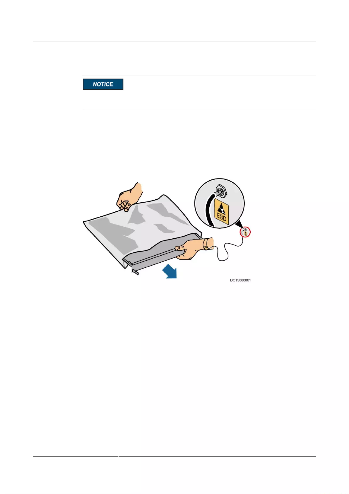
Wear a pair of ESD gloves or a well-grounded ESD wrist strap when touching the device
or handling boards or application-specific integrated circuits (ASICs).
When holding a board, hold its edge without touching any components, especially chips.
Package boards with ESD packaging materials before storing or transporting them.
Figure 1-1 shows how to wear an ESD wrist strap.
Figure 1-1 Wearing an ESD wrist strap
Liquid Prevention
Do not place the product under areas prone to water leakage, such as near air conditioner
vents, ventilation vents, or feeder windows of the equipment room. Ensure that there is
no condensation inside the product or equipment room. Ensure that no liquid enters the
product. Otherwise, short circuits will occur and may result in serious injury or death.
If any liquid is detected inside the product, immediately disconnect the power supply and
contact the administrator.
1.3 Operating Environment
The UPS is used for commercial and industrial purposes only. It cannot be used as a power
supply for life support devices.
The TIER4 or TIER3 power supply architecture specified in TIA942, that is, dual power
supply routes, must be used in the power supply systems that are crucial to major economic
interests or order of public places, such as the national computing center, military command
system, emergency command center, railway signal system and control center, civil aviation
UPS2000-G-(6 kVA-20 kVA)
User Manual
Copyright © Huawei Technologies Co., Ltd.
air traffic control center, airport command center, financial clearing center, and transaction
center.
Ensure that the product is used in an environment that meets the product design specifications
(including power grid, temperature, and humidity) to avoid causing malfunctions, damaging
components, or voiding the warranty.
The UPS operating environment must meet the requirements for the climate indicator,
mechanically active substance indicator, and chemically active substance indicator in ETSI
EN 300 019-1 class 3.6.
After unpacking the UPS, you are advised to power on the UPS as soon as possible. If you
temporarily do not use the UPS, take appropriate measures to prevent moisture, dust, and
foreign matter from entering the UPS.
After unpacking batteries, you are advised to connect the battery supply as soon as
possible. If you temporarily do not use the batteries, store them in dry and clean
environments. If batteries are stored for more than 90 days, charge them in time.
Otherwise, the battery lifespan may be affected.
Do not place the device in an environment that has inflammable and explosive air or gas. Do
not perform any operation in this kind of environment.
If the valid mains voltage exceeds 320 V AC, the UPS may be damaged.
Any operation on any electrical device in an environment that has inflammable air can cause
extreme danger. Strictly obey the operating environmental requirements specified in related
use manuals when using or storing the device.
Do not place the UPS in the following environments:
The environment that is close to flammable or explosive materials, dust, corrosive gases
or dust, conductive or magnetic dust, abnormal vibration, or collision.
Rooms or outdoor environments where temperature and humidity are not controlled
(with high temperature, low temperature, moisture, direct sunlight, or heat sources).
Non-confined environment near the ocean (0–3.7 km) and indoor or semi-indoor
environment where the temperature and humidity are not controllable, such as a simple
equipment room near the ocean, citizen house, garage, corridor, direct ventilation cabinet,
house with only the roof, railway station platform, gymnasium, aquarium, and so on.
The environment that is conducive for the growth of microorganisms such as fungus or
mildew.
The environment where rodents (such as mice) and insects exist.
1.4 Battery Safety
This section describes precautions for operating batteries.
UPS2000-G-(6 kVA-20 kVA)
User Manual
Copyright © Huawei Technologies Co., Ltd.
Before operating batteries, carefully read the safety precautions to ensure correct battery
handling and connection is performed, and personal safety is managed.
To ensure battery safety and efficient battery management, use the batteries delivered with
the UPS. Huawei shall not be responsible for battery damage caused by using non-Huawei
batteries for Huawei UPSs.
Ensure lead-acid battery handling is in accordance with local regulations.
Incorrect handling of batteries may cause hazards. When operating batteries, avoid
battery short circuits and electrolyte overflow or leakage.
Electrolyte overflow may damage the device by corroding metal parts and circuit boards,
and ultimately damaging the circuit boards.
Short circuits caused by incorrect operations may cause serious injuries due to high
power of batteries.
Do not reversely connect positive and negative battery terminals.
Use batteries of the specified type. Otherwise, the batteries may be damaged.
Check battery connections periodically to ensure that all screws are securely tightened.
Install or store batteries in clean, cool, and dry environments.
Do not decompose, transform, or damage batteries. Otherwise, battery short circuit,
electrolyte leakage, and even personal injury may occur.
Preventative Measures
When installing and maintaining batteries, pay attention to the following points:
Use dedicated insulated tools.
Take measures to protect eyes, such as using eye protection devices.
Avoid skin contact with electrolyte overflow. Wear rubber gloves and protective
clothing.
When handling a battery, ensure that its electrodes always point upward. Do not tilt or
overturn batteries.
Switch off the power supply during installation and maintenance.
Battery Short Circuit
Battery short circuits may cause personal injury. The high transient current generated by a
short circuit may release a surge of power and cause a fire.
To avoid battery short circuits, do not maintain batteries while they are in use.
UPS2000-G-(6 kVA-20 kVA)
User Manual
Copyright © Huawei Technologies Co., Ltd.
Harmful Gas
Do not use unsealed lead-acid batteries. Lead-acid batteries emit flammable gas. Therefore,
place and secure lead-acid batteries horizontally to prevent fire or corrosion.
Store lead-acid batteries in a place with good ventilation, and take fire safety precautions.
Battery Temperature
High temperature may result in battery distortion, damage, and electrolyte overflow.
Install or store batteries far away from fire sources and heating devices such as
transformers. Never burn batteries.
If the battery temperature exceeds 60°C, check the battery for electrolyte overflow. If
electrolyte overflows, handle the leakage immediately.
Electrolyte Leakage
In the case of electrolyte leakage, counteract and absorb the leaking electrolyte immediately.
When moving or handling a battery whose electrolyte leaks, note that the leaking electrolyte
may harm human bodies. If the electrolyte leaks, use the following substances to counteract
and absorb the leaking electrolyte:
Sodium bicarbonate (baking soda): NaHCO3
Sodium carbonate (soda): Na2CO3
When using substances to counteract and absorb electrolytes, strictly follow the guidelines
provided by the battery manufacturer.
If any personnel are exposed to battery electrolyte, wash the exposed area with clean water
immediately and seek medical advice if the situation is serious.
1.5 Mechanical Safety
Moving Sharp Objects
UPS2000-G-(6 kVA-20 kVA)
User Manual
Copyright © Huawei Technologies Co., Ltd.
Wear protective gloves when moving sharp objects.
Moving Heavy Objects
Perform operations in accordance with all instructional symbols on the device.
Take caution to avoid injury when moving heavy objects.
When moving or lifting a device, hold the handle or bottom of the device.
Move the cabinet with caution. Any bumping or falling may damage the device.
Handling Fans
Do not insert fingers or boards into the operating fans until the fans are switched off, and have
stopped running.
1.6 Laying Out Cables
Binding Signal Cables
Signal cables must be bound separately from strong-current cables and high-voltage cables.
Laying Out Cables
When the temperature is low, a violent strike or vibrations may damage the cable sheathing.
To ensure cable safety, comply with the following requirements:
Cables can be laid, or installed, only when the temperature is higher than 0°C (32°F).
Handle cables with caution, especially at lower temperatures.
Before laying out cables that have been stored in temperatures lower than 0°C (32°F),
move the cables to an environment that is at the requisite ambient temperature. Store
them in this environment for at least 24 hours.
Do not drop the cables directly from the vehicle.
As the insulation layer of a cable may age, or be damaged from high temperatures,
ensure a sufficient distance between cables and the DC busbars, shunts, and fuses.
Cables prepared by the customer should be flame resistant. Cables must not be routed
behind the air exhaust vent of the cabinet. The air exhaust vent should not be blocked by
any object.
Before connecting a cable, ensure that the cable and cable label to be used meet the actual
installation requirements.
UPS2000-G-(6 kVA-20 kVA)
User Manual
Copyright © Huawei Technologies Co., Ltd.
2 Quick Introduction
2.1 Model Description
This document describes the following UPS models:
UPS2000-G-6 kVA
standard model
The two models are represented by
UPS2000-G-6 kVA in the description
of their common features and
parameters.
UPS2000-G-6 kVA
long backup time model
UPS2000-G-10 kVA
standard model
The two models are represented by
UPS2000-G-10 kVA in the
description of their common features
and parameters.
UPS2000-G-10 kVA
long backup time model
The UPS2000-G-15KRTL has only a
long backup time model.
The UPS2000-G-20KRTL has only a
long backup time model.
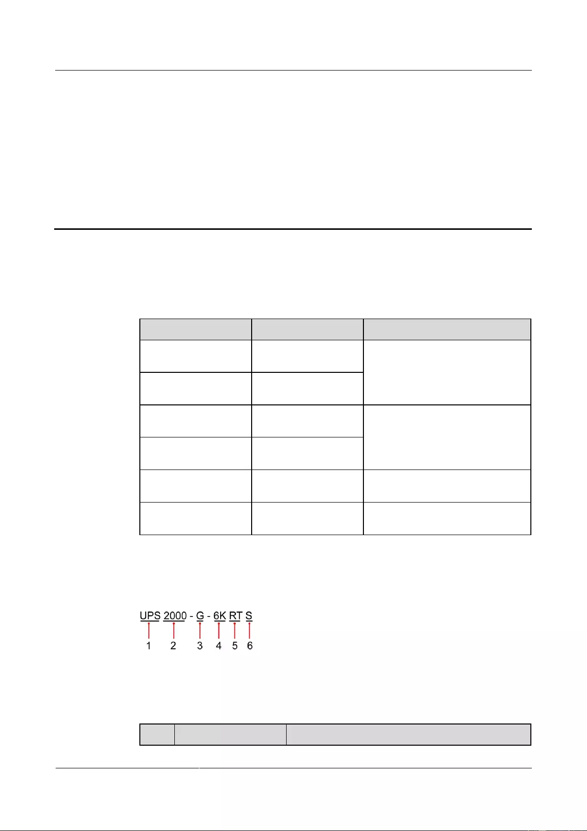
Figure 2-1 shows a UPS model number.
Figure 2-1 Model number
Table 2-1 describes the model number.
Table 2-1 Model number details
UPS2000-G-(6 kVA-20 kVA)
User Manual
Copyright © Huawei Technologies Co., Ltd.
6K: 6 kVA
10K: 10 kVA
15K: 15 kVA
20K: 20 kVA
RT: rack- and tower-mounted unit
RR: rack-mounted unit
TT: tower-mounted unit
TM: modular tower-mounted unit
RM: modular rack-mounted unit
Built-in battery
(optional)
S: standard model, which provides only a standard
battery pack.
L: long backup time model. You need to use an external
large-capacity battery pack.
2.2 Working Principle
2.2.1 Conceptual Diagram
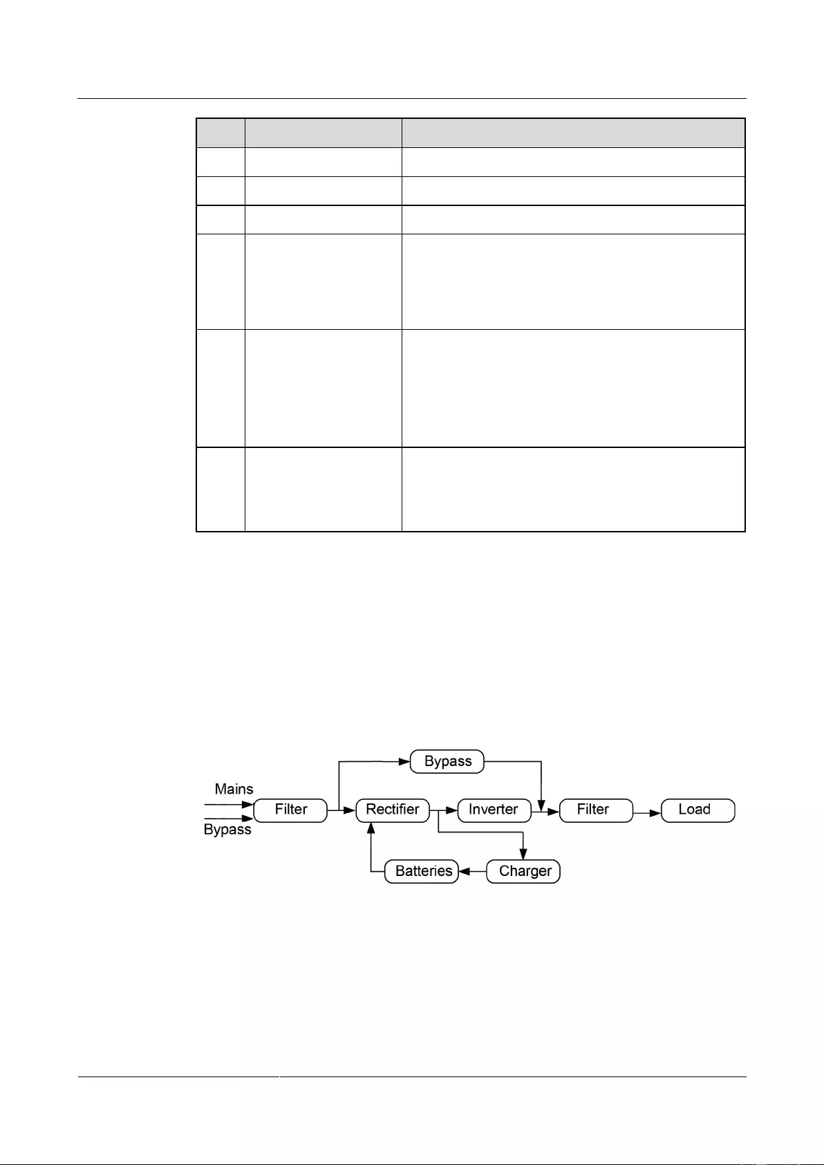
Figure 2-2 shows the UPS conceptual diagram.
Figure 2-2 Conceptual diagram
2.2.2 Working Modes
The UPS has the following working modes:
Normal mode

UPS2000-G-(6 kVA-20 kVA)
User Manual
Copyright © Huawei Technologies Co., Ltd.
When the mains is normal, the rectifier boosts the mains input voltage and converts the
AC power into stable DC power for the inverter, and the mains charges batteries over a
charger. Then the inverter converts the DC power into stable AC power, which is
supplied to loads.
Battery mode
When the mains is abnormal or disconnected, the DC-DC step-up transformer boosts the
DC power supplied from batteries. Then the inverter converts the DC power into stable
AC power for powering loads.
Bypass mode
The mains supplies power directly to loads after filtering. The UPS transfers to bypass
mode when overload, overtemperature, or faults occur. This mode does not provide
battery backup capability.
Economy control operation (ECO) mode
If the bypass voltage and frequency are in the specified range, the UPS supplies power to
loads over the bypass. If the bypass voltage and frequency are outside the range, the UPS
transfers to normal or battery mode. ECO is short for economy control operation.
The UPS2000-G-15 kVA/20 kVA supports battery ECO mode only in the case of two mains inputs.
In battery ECO mode, the bypass supplies power to the UPS, and batteries are used as backup power.
If the bypass is abnormal, the UPS transfers to battery mode.
By default, ECO mode described in this document refers to mains ECO mode.
2.3 Appearance
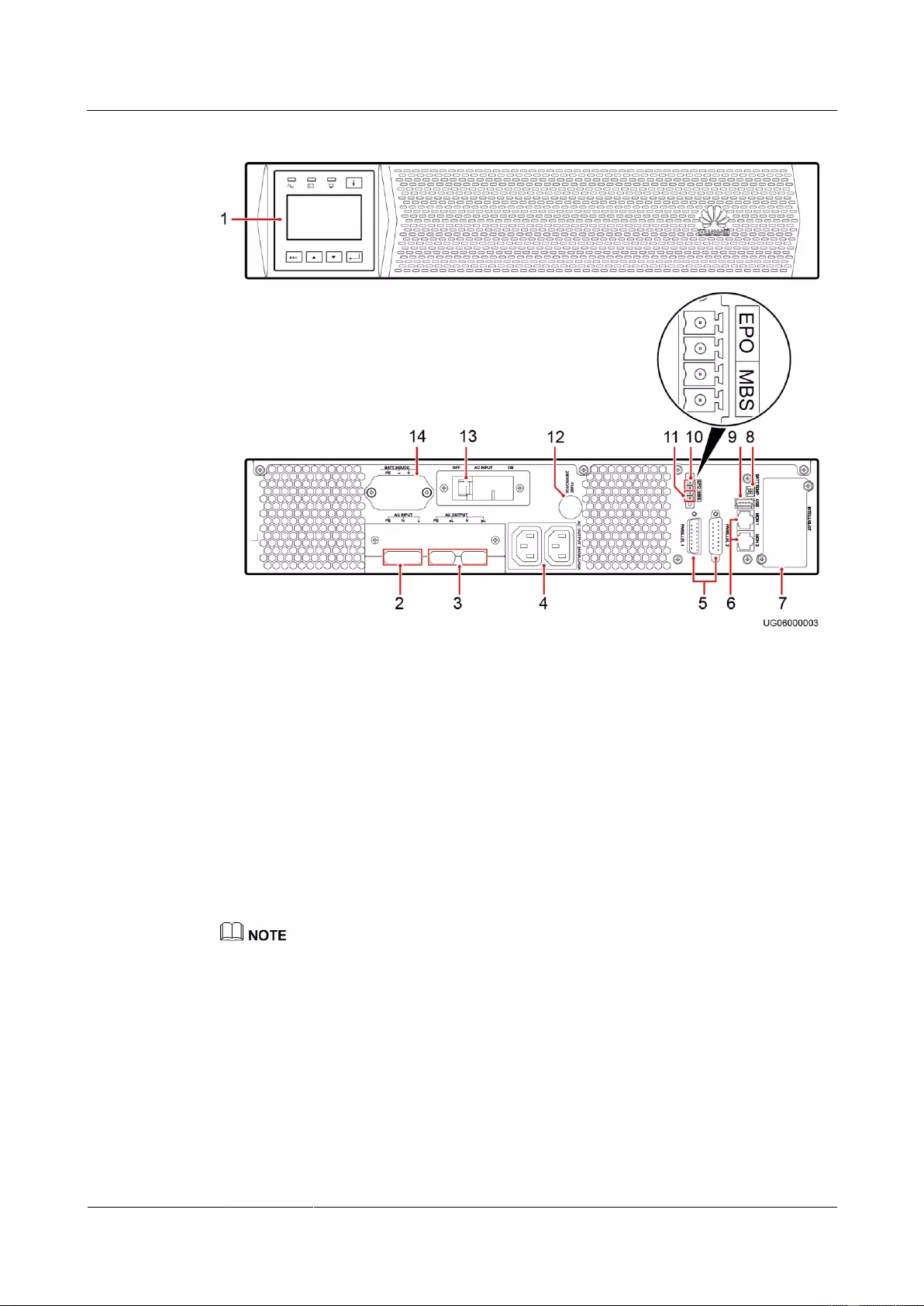
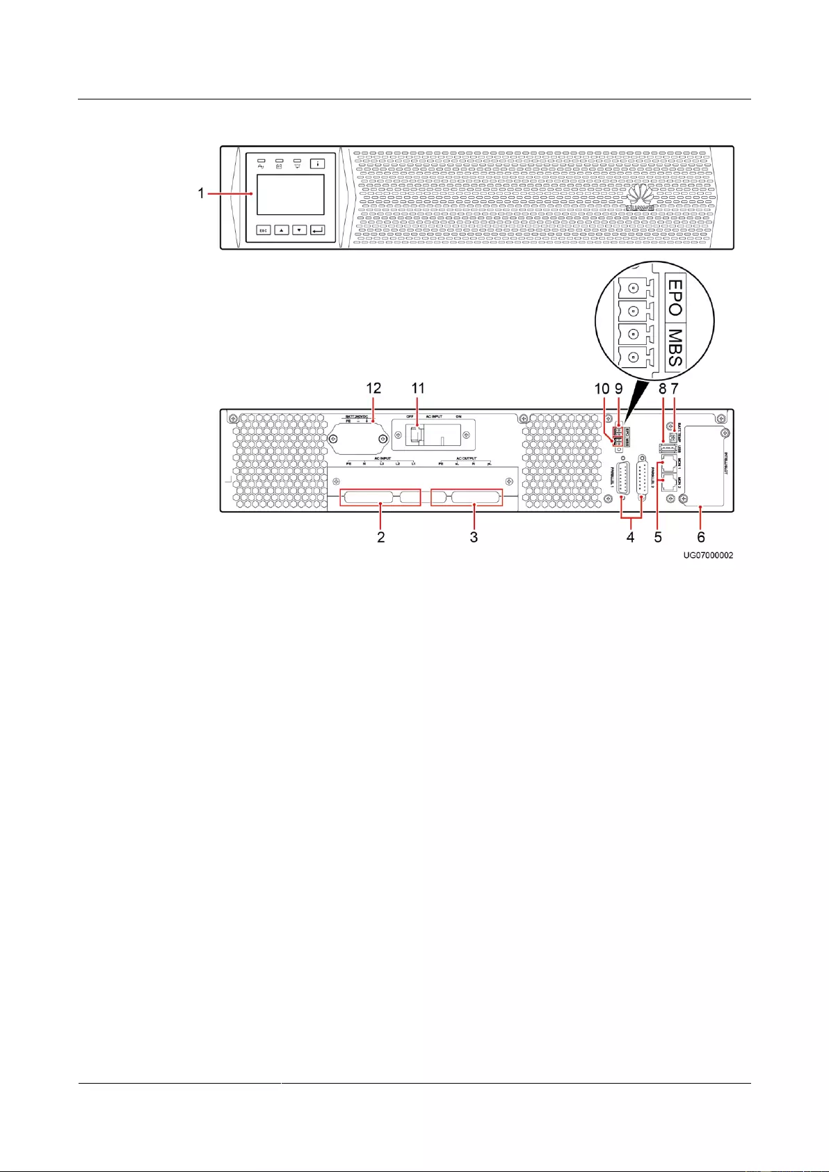
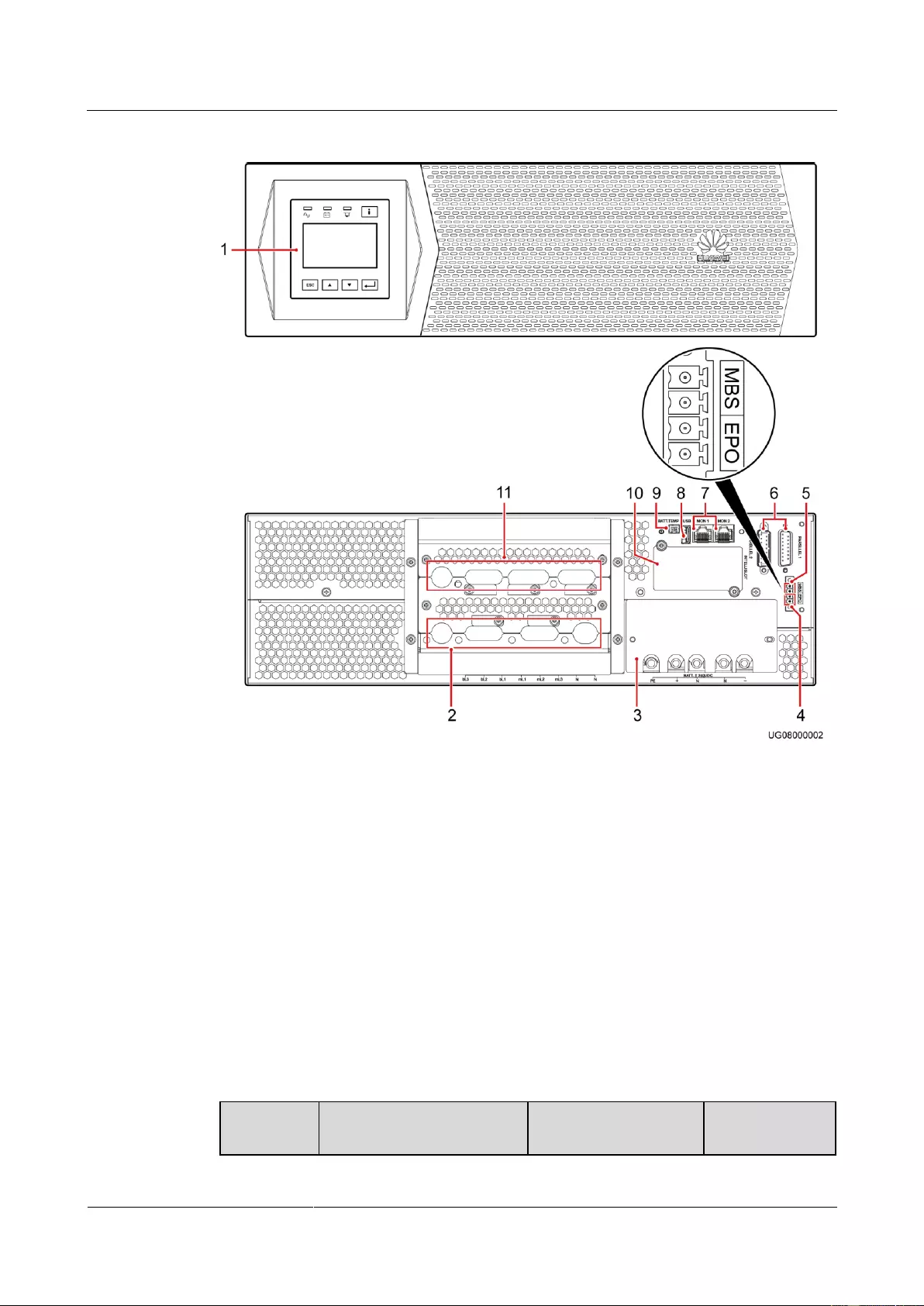
Figure 2-3 shows the front and rear views of the UPS2000-G-6 kVA. Figure 2-4 shows the
front and rear views of the UPS2000-G-10 kVA. Figure 2-5 shows the front and rear views of
the UPS2000-G-15 kVA/20 kVA.
UPS2000-G-(6 kVA-20 kVA)
User Manual
Copyright © Huawei Technologies Co., Ltd.
Figure 2-3 Front and rear views of the UPS2000-G-6 kVA
(3) AC output
ports (pL and sL)
(6) Control area network
(CAN) communications ports
(MON1 and MON2)
(8) Battery
temperature
sensor port
(9) Universal
Serial Bus
(USB) port
(10) Emergency power-off
(EPO) port
(11) Maintenance
bypass port
(MBS)
(13) Input
circuit breaker
The total load current supported by the two output sockets (C13) cannot exceed 10 A.
The fuse used on the UPS2000-G-6 kVA meets the 250V—10A-IEC specifications.
UPS2000-G-(6 kVA-20 kVA)
User Manual
Copyright © Huawei Technologies Co., Ltd.
Figure 2-4 Front and rear views of the UPS2000-G-10 kVA
(3) AC output ports
(pL and sL)
(5) CAN communications
ports (MON1 and MON2)
(7) Battery
temperature sensor
port
(10) Maintenance
bypass port (MBS)
(11) Input circuit
breaker
UPS2000-G-(6 kVA-20 kVA)
User Manual
Copyright © Huawei Technologies Co., Ltd.
Figure 2-5 Front and rear views of the UPS2000—G-15 kVA/20 kVA
(2) AC input ports
(mains and bypass)
(5) Maintenance
bypass port (MBS)
(7) CAN communications ports
(MON1 and MON2)
(9) Battery
temperature sensor
port
(11) AC output ports (pL and
sL)
2.4 Optional Components
Table 2-2 Optional components

UPS2000-G-(6 kVA-20 kVA)
User Manual
Copyright © Huawei Technologies Co., Ltd.
DB15M, CC8P0.48B(S),
DB15F
Connect UPSs in
parallel.
A parallel cable
is 1.5 meters
long.
Battery
temperature
sensor
Measures the ambient
temperature of the
external power module
and battery pack.
The temperature
ranges from
–40ºC to +80ºC.
The standard
cable is 2 meters
long. To increase
the length, install
a magnetic ring
at the sensor
plug.
Ambient
temperature
and
humidity
sensor
WS302M2A-5
ENR1DETA MODULE
Measures the UPS
ambient temperature
and humidity. The
ambient temperature
ranges from 0–50ºC.
The ambient humidity
ranges from to
0%–100% RH.
It is used
together with a
Simple Network
Management
Protocol (SNMP)
card.
Monitors the UPS and
the ambient
temperatures and
humidity (if required)
and allows for Ethernet
networking.
6 kVA
output
isolation
transformer
box
Provides isolation
solutions for customer
equipment. Compared
with the output
transformer on an
industrial frequency
UPS, the output
transformer box
provides isolation
functions even in
bypass mode. The
isolation transformer is
a 2:1:1
industrial-frequency
transformer. It converts
one 220 V output
voltage into two
isolated 110 V outputs.
The output
isolation
transformer box
is 6 kVA,
single-phase. It is
used for the
UPS2000-G-6
kVA.
10 kVA
output
isolation
transformer
box
The output
isolation
transformer box
is 10 kVA,
single-phase. It is
used for the
UPS2000-G-10
kVA.
Standard
battery pack
(7 Ah, 20
ESS-240V12-7AhBPVBA01
ESS-240V12-7AhBPVBA02
Each battery pack
consists of twenty 12 V,
7 Ah VRLA batteries
The
UPS2000-G-15
kVA/20 kVA

UPS2000-G-(6 kVA-20 kVA)
User Manual
Copyright © Huawei Technologies Co., Ltd.
connected in series. It is
a standard configuration
for the UPS2000-G-6
kVA. A maximum of
four battery packs are
connected in parallel.
uses at least two
battery packs.
Standard
battery pack
(9 Ah, 20
batteries)
ESS-240V12-9AhBPVBA01
ESS-240V12-9AhBPVBA02
Each battery pack
consists of twenty 12 V,
9 Ah VRLA batteries
connected in series. It is
a standard configuration
for the UPS2000-G-10
kVA. A maximum of
four battery packs are
connected in parallel.
Provides two cascaded
RJ45 ports to
implement networking
over the Modbus or
YDN-23 protocol.
Provides six alarm dry
contact outputs (normal
mode, battery mode,
bypass mode, low
battery voltage, bypass
backfeed, and UPS
faults) and two dry
contract control inputs
(one is the shutdown
signal input, and the
other is reserved).
External dry
contact card
Provides four dry
contact outputs (critical
alarm, minor alarm,
mains mode, battery
mode, bypass mode,
inverter on, battery
undervolt., bypass
backfeed, high ambient
tempreture, or UPS
fault.) and two dry
contract inputs (startup,
shutdown).
Used together
with an SNMP
card.
Consists of the
communication
interface module (CIM)
and battery interface
module (BIM). The
CIM is an intelligent
Used together
with an SNMP
card.
UPS2000-G-(6 kVA-20 kVA)
User Manual
Copyright © Huawei Technologies Co., Ltd.
battery management
module which collects
wireless communication
data of battery status
from the downstream
BIM groups, and
uploads data to the
SNMP card through the
COM port.
Power
distribution
unit (PDU)
(PDC-0038
V4ACIOA)
Controls and protects
input and output power,
increases output
sockets, and distributes
power for 1+1 parallel
systems, and
implements online
maintenance.
The PDU is
designed for a
1+1
UPS2000-G-15
kVA/20 kVA
parallel system
(three-phase
input three-phase
output).
The PDU is
designed for a
1+1
UPS2000-G-
15 kVA/20
kVA parallel
system
(three-phase
input
single-phase
output and
single-phase
input
single-phase
output).
It can also be
used in a
UPS2000-G-
6 kVA/10
kVA 1+1
parallel
system and
2+0 parallel
system.
DN85H, H38x22x15
(DMEGC)
E2F, 38x22x15 (FENGYI)
Optimizes the
performance of the
TN-C power
distribution system in
the parallel system
scenario.
In a
UPS2000-G-15
kVA/20 kVA
parallel system
using the TN-C
power
distribution
system, install
UPS2000-G-(6 kVA-20 kVA)
User Manual
Copyright © Huawei Technologies Co., Ltd.
four magnetic
rings on the PE
cables on each
UPS, bind the
four magnetic
rings together
using binding
tape, and secure
them to the
nearest place.
It is recommended that you install the battery temperature sensor (secured with an adhesive) on the
surface of batteries in the middle of the battery rack.
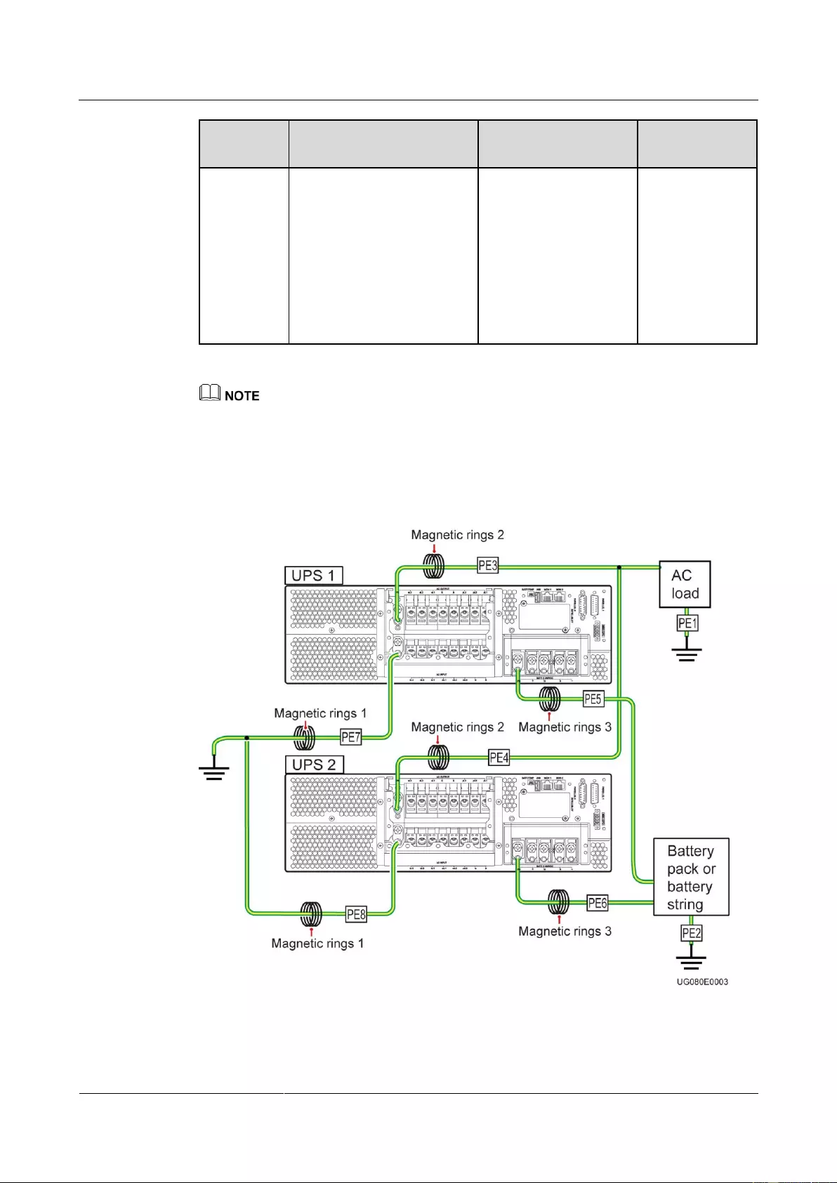
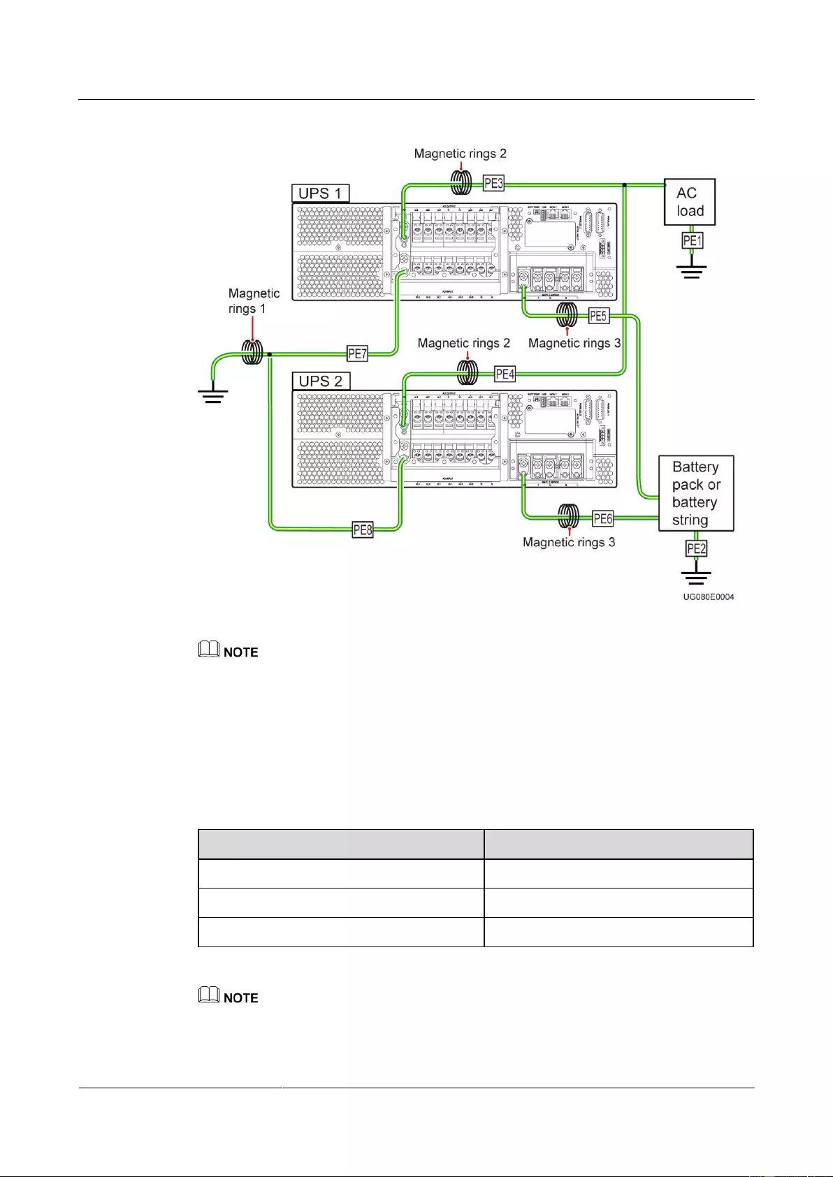
In a UPS2000-G-15 kVA/20 kVA parallel system using the TN-C power distribution system,
there are two scenarios for installing magnetic rings on the UPS mains input PE cables:
Figure 2-6 Installing magnetic rings (numbered 1) on branch PE cables
UPS2000-G-(6 kVA-20 kVA)
User Manual
Copyright © Huawei Technologies Co., Ltd.
Figure 2-7 Installing a magnetic ring (numbered 1) on the general PE cable
Perform the following operations in a parallel system using the TN-C power distribution system:
Short-circuit battery terminals N in the parallel system.
It is recommended that you connect AC loads and battery packs only to the UPS PE terminal.
If you have directly grounded AC loads and battery packs and connected them to the UPS PE
terminal, install magnetic rings 2 and 3 on the PE3, PE4, PE5, and PE6 ground cables. You need to
purchase magnetic rings 2 and 3.
The recommended type for magnetic rings 1, 2, and 3 is DN85Hx4 or E2Fx4.
Table 2-3 Specifications of magnetic rings from three vendors
The magnetic conductivity of manganese and zinc magnetic rings is greater than 10,000, and the
recommended internal diameter of magnetic rings is greater than 10 mm (easy for wire coiling). The
number of coiling circles is 5 or greater.

UPS2000-G-(6 kVA-20 kVA)
User Manual
Copyright © Huawei Technologies Co., Ltd.
3 Installation
3.1 Preparations
3.1.1 Site
Floor Bearing
The floor can bear the weight of the UPS and its optional components. In the case of rack
installation, ensure that the floor can also bear the weight of the rack.
Environment
Do not install the UPS in an environment outside the specifications.
Keep the UPS far away from water, heat sources, and flammable and explosive
substances. Install the UPS in an environment free of dust, volatile gas, salt, and
corrosive materials. Avoid direct sunlight.
Do not install the UPS in environments with conductive metal scraps in the air.
The ideal operating temperature for batteries is 20–30ºC. Temperatures higher than 30ºC
shorten the battery lifespan and temperatures lower than 20ºC reduces the backup time.
UPS2000-G-(6 kVA-20 kVA)
User Manual
Copyright © Huawei Technologies Co., Ltd.
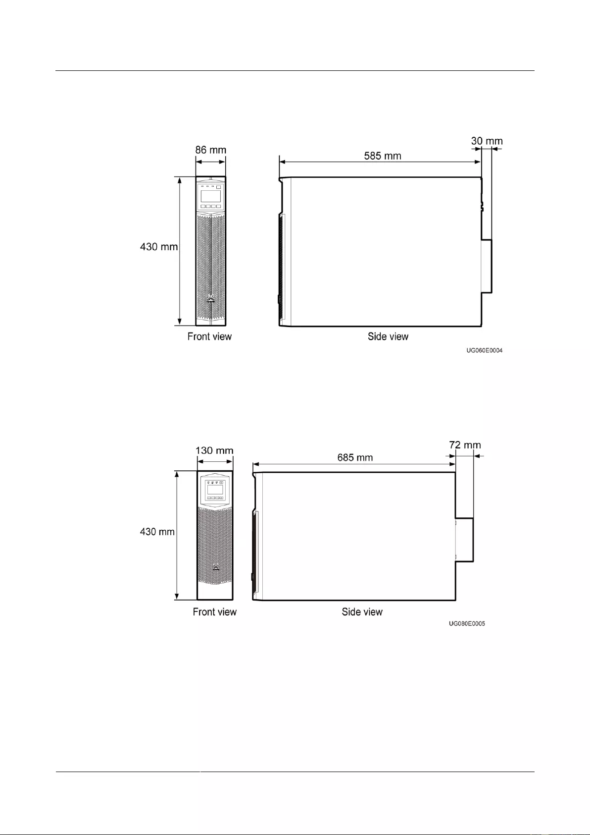
UPS2000-G-6 kVA/10 kVA Dimensions
Figure 3-1 UPS2000-G—6 kVA/10 kVA installation dimensions
UPS2000-G-15 kVA/20 kVA Dimensions
Figure 3-2 UPS2000-G—15 kVA/20 kVA installation dimensions
Clearances
UPS2000-G-(6 kVA-20 kVA)
User Manual
Copyright © Huawei Technologies Co., Ltd.
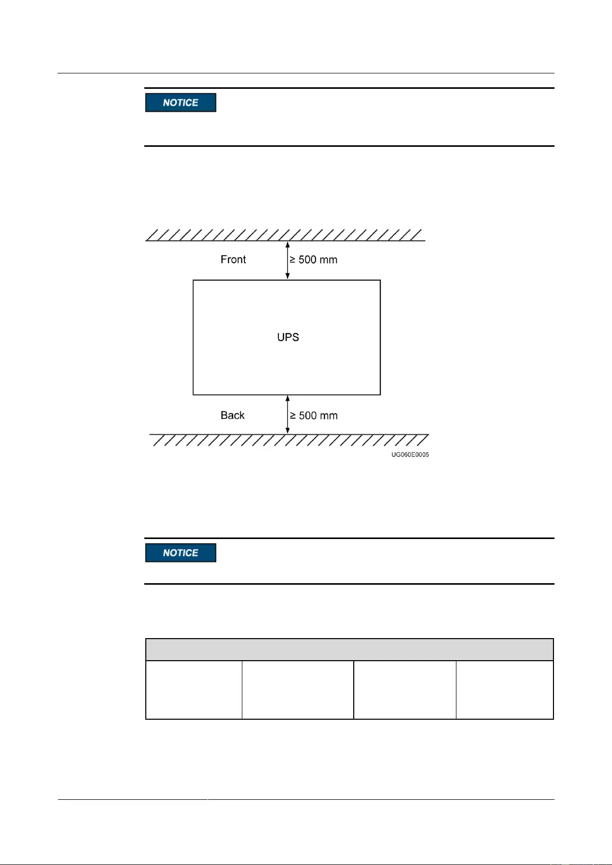
The distance between UPS air vents and the wall or obstacle is greater than or equal to 500
mm.
Reserve a clearance of at least 500 mm respectively from the front and rear panels of the UPS
to the wall or adjacent equipment to facilitate ventilation and heat dissipation, as shown in
Figure 3-3.
Figure 3-3 Reserved clearances
3.1.2 Tools
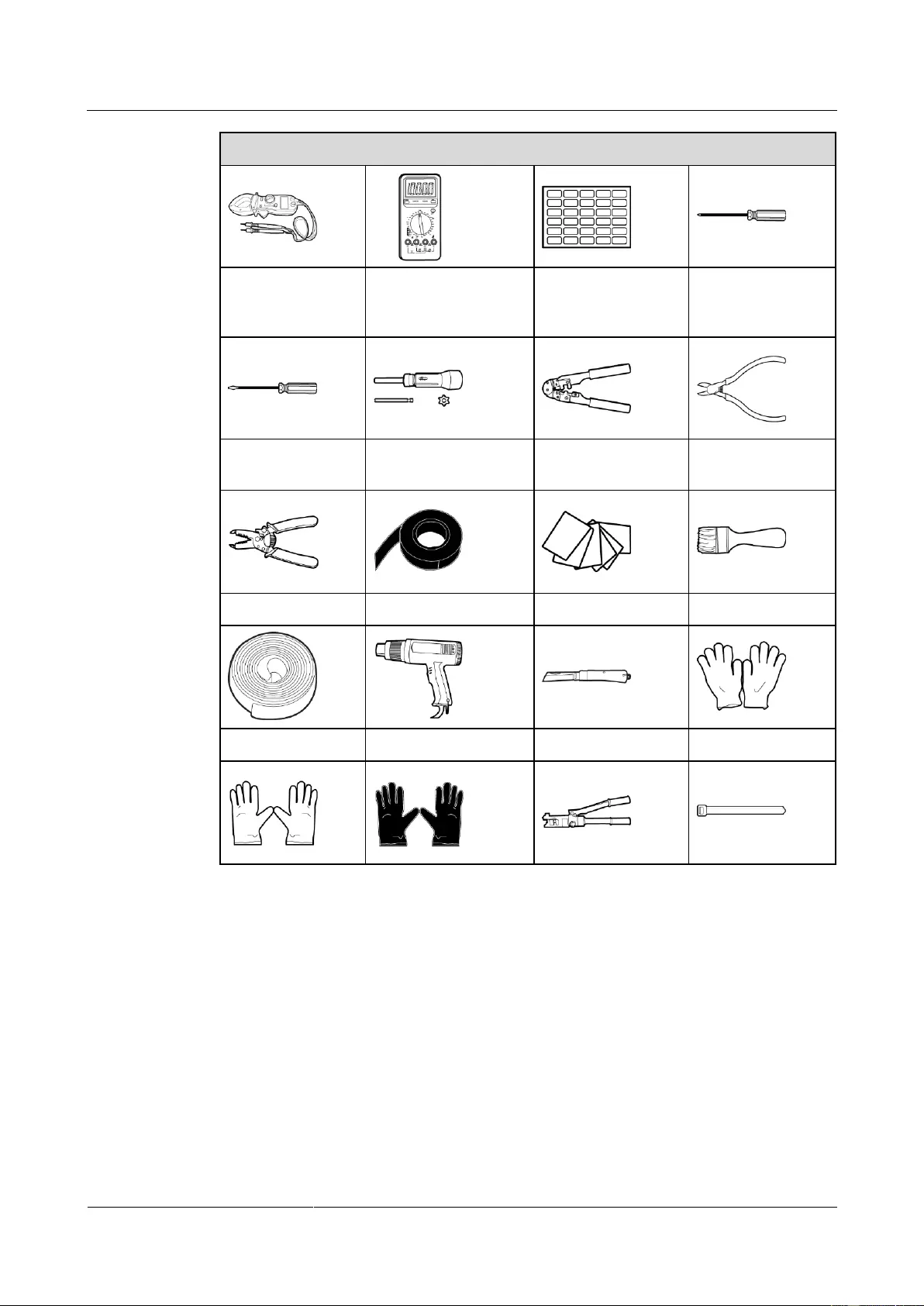
Get installation tools insulated to prevent electric shocks.
Table 3-1 lists the installation tools.
Table 3-1 Tools
Phillips
screwdriver (PH 2
x 150 mm or PH 3
x 250 mm)
UPS2000-G-(6 kVA-20 kVA)
User Manual
Copyright © Huawei Technologies Co., Ltd.
Flat-head
screwdriver (2 mm
x 80 mm)
Polyvinyl chloride
(PVC) insulation tape
3.1.3 Power Cables
UPS2000-G-(6 kVA-20 kVA)
User Manual
Copyright © Huawei Technologies Co., Ltd.
In the case of three-phase input, install a three-phase disconnector. In the case of
single-phase input, you are advised to install a disconnector.
When used to power IT system, the UPS (three-phase output) should provide 4-pole
disconnectors, and the UPS (single-phase output) should provide 2-pole disconnectors.
The UPS is a large leakage current device. Do not configure a circuit breaker that has the
leakage current protection function. If you need leakage current protection function, use
the earth leakage circuit breaker recommended.
The battery cable cannot be longer than 10 m.
You can install linked circuit breakers for both the N wire and L wire. No independent
circuit breaker is allowed for only the N wire.
For 15 kVA/20 kVA model, use AC ground cables that have a cross-sectional area of 25
mm2 and M6 OT terminals that are 90° bent and have a cross-sectional area of 25 mm2.
For 15 kVA/20 kVA model, use battery ground cables that have a cross-sectional area of
16 mm2 and M6 OT terminals that are 90° bent and have a cross-sectional area of 16 mm2.
For 6 kVA model, use ground cables that have a cross-sectional area of 6 mm2 and M4 OT
terminals and have a cross-sectional area of 6 mm2.
For 10 kVA model, use ground cables that have a cross-sectional area of 10 mm2 and M6
OT terminals and have a cross-sectional area of 10 mm2.
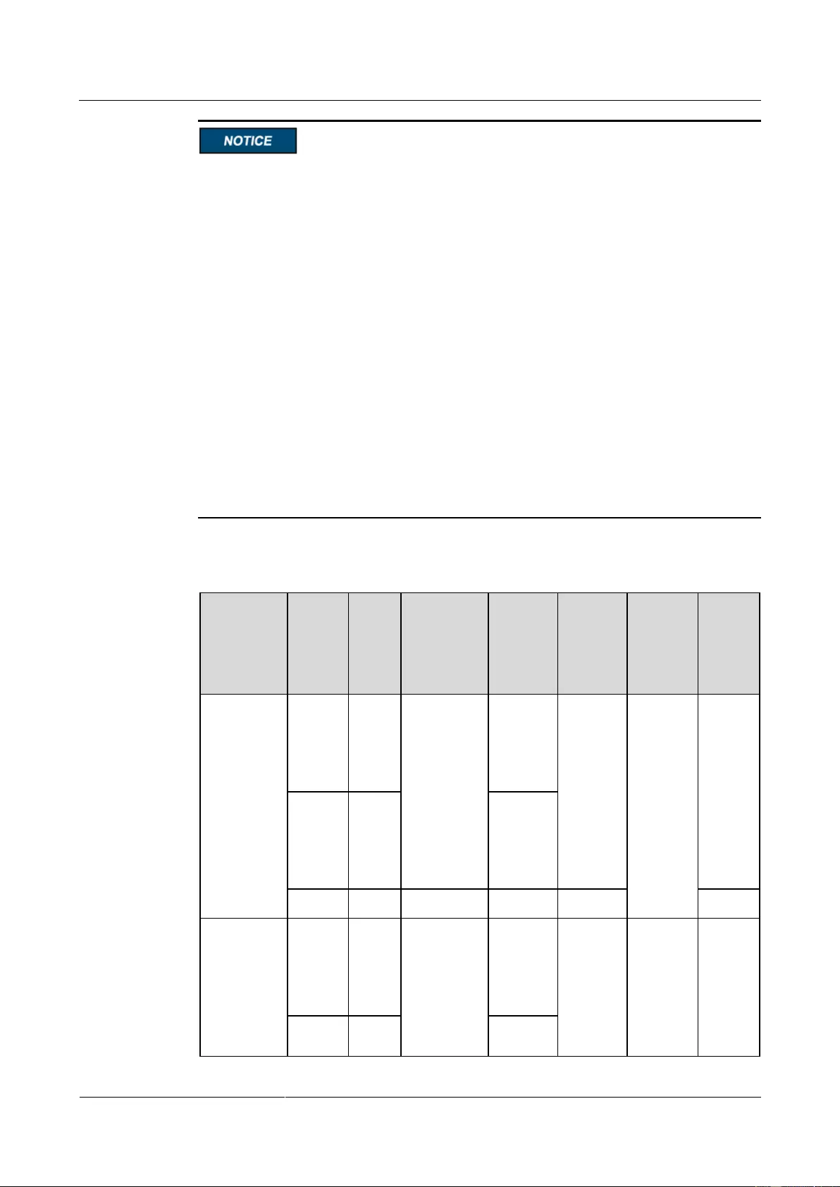
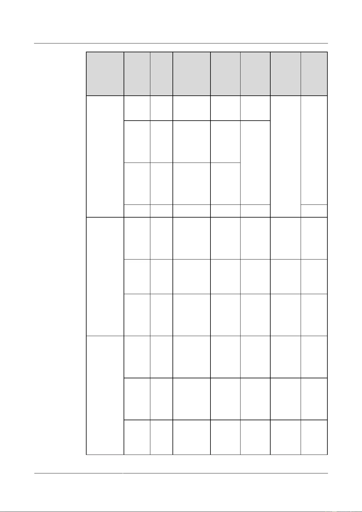
Table 3-2 lists the recommended power cable specifications.
Table 3-2 Recommended power cable specifications
Torqu
e for
Tighte
ning
Bolts
220 V AC,
230 V AC,
or 240 V
AC
50 A
(the
characte
ristics of
D)
50 A
(the
characte
ristics of
D)
220 V AC,
230 V AC,
or 240 V
AC
63 A
(the
characte
ristics of
D)
UPS2000-G-(6 kVA-20 kVA)
User Manual
Copyright © Huawei Technologies Co., Ltd.
Torqu
e for
Tighte
ning
Bolts
380 V AC,
400 V AC,
or 415 V
AC
63 A
(the
characte
ristics of
D)
220 V AC,
230 V AC,
or 240 V
AC
63 A
(the
characte
ristics of
D)
15 kVA
(single-pha
se input
single-phas
e output)
220 V AC,
230 V AC,
or 240 V
AC
100 A
(the
characte
ristics of
D)
16 mm2
M6 90°
OT
terminal
220 V AC,
230 V AC,
or 240 V
AC
100 A
(the
characte
ristics of
D)
15 kVA
(three-phas
e input
single-phas
e output)
220 V AC,
230 V AC,
or 240 V
AC
100 A
(the
characte
ristics of
D)
380 V AC,
400 V AC,
or 415 V
AC
50 A
(the
characte
ristics of
D)
16 mm2
M6 90°
OT
terminal

UPS2000-G-(6 kVA-20 kVA)
User Manual
Copyright © Huawei Technologies Co., Ltd.
Torqu
e for
Tighte
ning
Bolts
220 V AC,
230 V AC,
or 240 V
AC
100 A
(the
characte
ristics of
D)
15 kVA
(three-phas
e input
three-phase
output)
380 V AC,
400 V AC,
or 415 V
AC
50 A
(the
characte
ristics of
D)
16 mm2
M6 90°
OT
terminal
380 V AC,
400 V AC,
or 415 V
AC
50 A
(the
characte
ristics of
D)
20 kVA
(single-pha
se input
single-phas
e output)
220 V AC,
230 V AC,
or 240 V
AC
125 A
(the
characte
ristics of
D)
16 mm2
M6 90°
OT
terminal
220 V AC,
230 V AC,
or 240 V
AC
125 A
(the
characte
ristics of
D)
20 kVA
(three-phas
e input
single-phas
e output)
220 V AC,
230 V AC,
or 240 V
AC
125 A
(the
characte
ristics of
D)
380 V AC,
400 V AC,
or 415 V
AC
63 A
(the
characte
ristics of
D)

UPS2000-G-(6 kVA-20 kVA)
User Manual
Copyright © Huawei Technologies Co., Ltd.
Torqu
e for
Tighte
ning
Bolts
16 mm2
M6 90°
OT
terminal
220 V AC,
230 V AC,
or 240 V
AC
125 A
(the
characte
ristics of
D)
20 kVA
(three-phas
e input
three-phase
output)
380 V AC,
400 V AC,
or 415 V
AC
63 A
(the
characte
ristics of
D)
16 mm2
M6 90°
OT
terminal
380 V AC,
400 V AC,
or 415 V
AC
63 A
(the
characte
ristics of
D)
If customers purchase input and output power cables by themselves, use the cables that comply with
standards proposed by Underwriters Laboratories (UL) or International Electrotechnical
Commission (IEC).
Two-mains-input scenarios are not supported on the UPS2000-G-15 kVA/20 kVA (single-phase
input single-phase output).
3.1.4 Unpacking and Checking
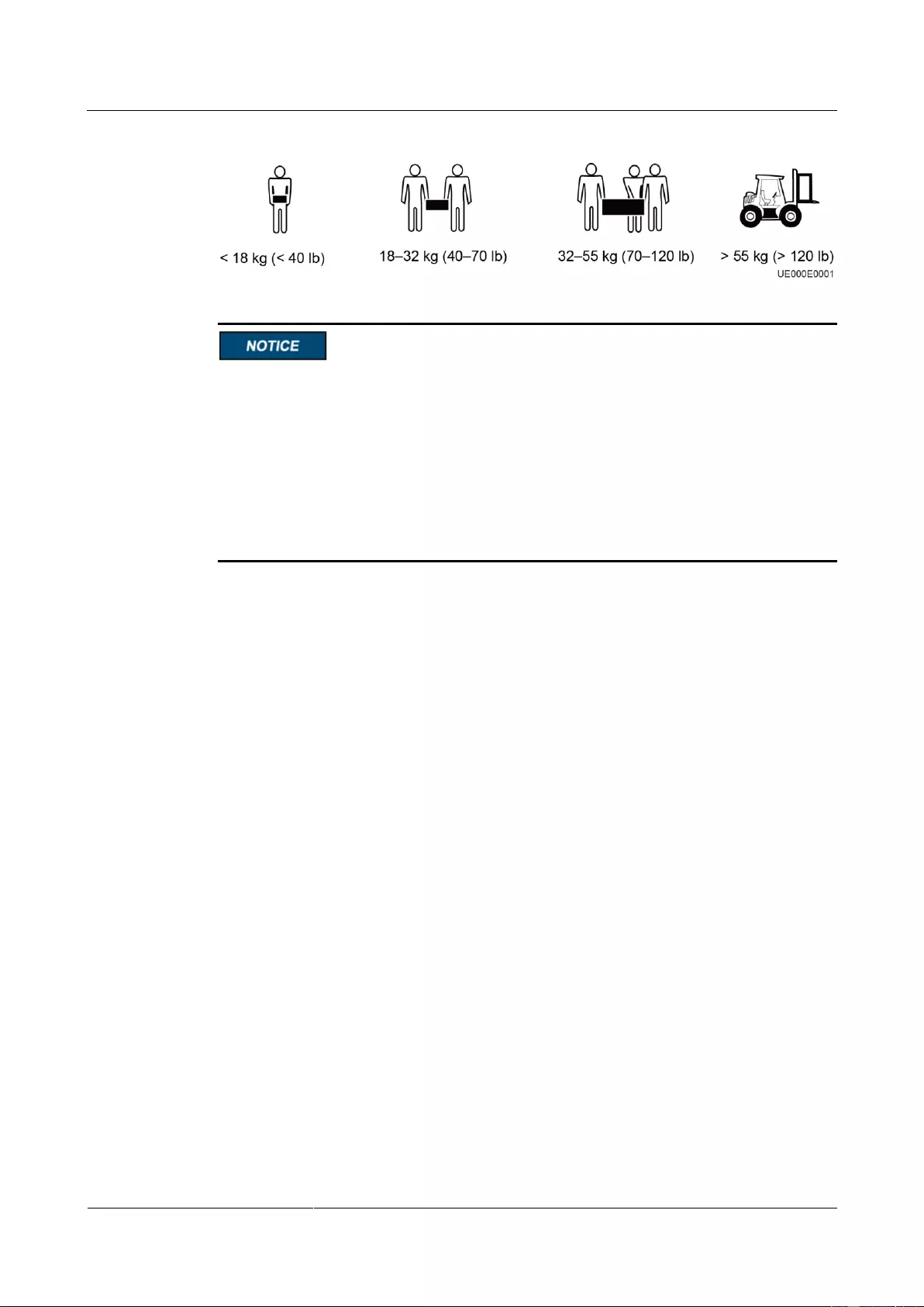
Figure 3-4 shows the transportation safety requirements.
UPS2000-G-(6 kVA-20 kVA)
User Manual
Copyright © Huawei Technologies Co., Ltd.
Figure 3-4 Transportation safety requirements
Only trained personnel are allowed to move the UPS.
Do not move the UPS by holding its mounting ears, front panel, terminal cover, or
monitoring module.
At least two persons are required to move the battery pack and transformer because they
are heavy. Exercise caution when moving them. Prevent the battery pack from falling over;
otherwise, fire accidents may occur. Remove rings, watches, and other metal objects when
you move the battery pack.
To prevent shocks or falls, move the UPS gently. After placing the UPS in the installation
position, unpack it carefully to prevent scratches.
Procedure
Step 1 Visually inspect the UPS appearance for shipping damage. If any shipping damage is found,
report it to the carrier immediately.
Step 2 Move the UPS to the installation position.
Step 3 Unpack the case.
Step 4 Check the UPS packing.
1. Check the UPS bar code (which is at the rear panel of the UPS, near the air exhaust vent),
and ensure that it complies with the order.
2. If there is any discrepancy, contact your local Huawei office immediately.
—-End
3.2 Installation Procedure
UPS installation includes mechanical installation and cable connection. Installation modes
include tower installation and rack installation. You can select an installation mode based on
the site requirements.
3.3 Installing a Backfeed Protection Device
3.3.1 Backfeed Protection Device Specifications
UPS2000-G-(6 kVA-20 kVA)
User Manual
Copyright © Huawei Technologies Co., Ltd.
The UPS has no built-in backfeed protection device. You can install a backfeed protection
device on the input front side.
If you do no install a backfeed protection device on the input front side, attach a warning label
to the main power isolation device. The label reads like this: «This circuit supplies power to
the UPS. Before cable connection, disconnect the UPS, and check the voltage across wiring
terminals.»
When battery mode is unavailable or the mains fails, the UPS internal voltages or energy may
flow back directly, or through a leakage path, to an input terminal. To minimize the risk of
electric shocks, install a backfeed protection device on the input side.
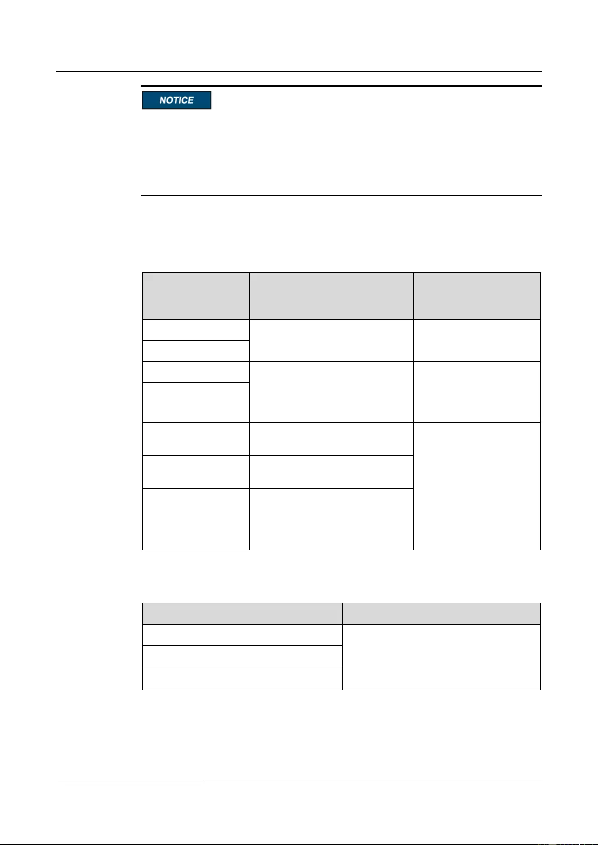
Table 3-3 Rated voltages and currents for backfeed protection contactors
Rated Voltage and Current
Recommended
Contactor Models
(Schneider contactors)
LC1-D50A for
single-phase input
LC1-DT60A for
three-phase input
UPS2000-G-15KRTL
(three-phase input)
LC1-D80 for
single-phase input
LC1-DT60A for
three-phase input
UPS2000-G-20KRTL
(three-phase input)
UPS2000-G-15KRTL
(single-phase input)
UPS2000-G-20KRTL
(single-phase input)
Table 3-4 Control relay parameters
HF18FF/012 (HONGFA control relay)
Dry contact: NC
Breaking capability: 250 V AC, 5 A
Coil: 12 V rated voltage; rated current of
less than 1 A
MY2N-J DC12V (OMRON control relay)
HJ2-L-DC12V (Panasonic control relay)
UPS2000-G-(6 kVA-20 kVA)
User Manual
Copyright © Huawei Technologies Co., Ltd.
3.3.2 Feedback Prevention Connections (With Dry Contract
Control)
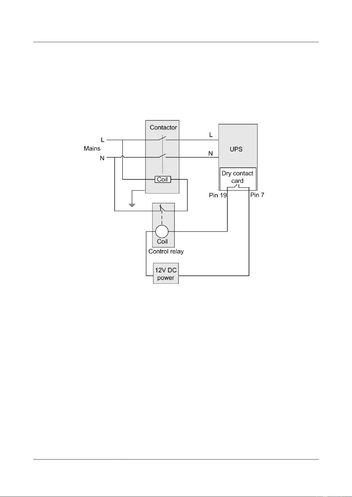
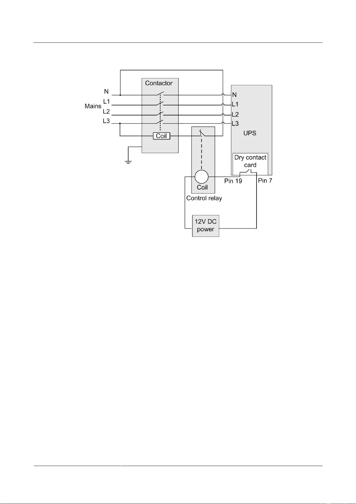
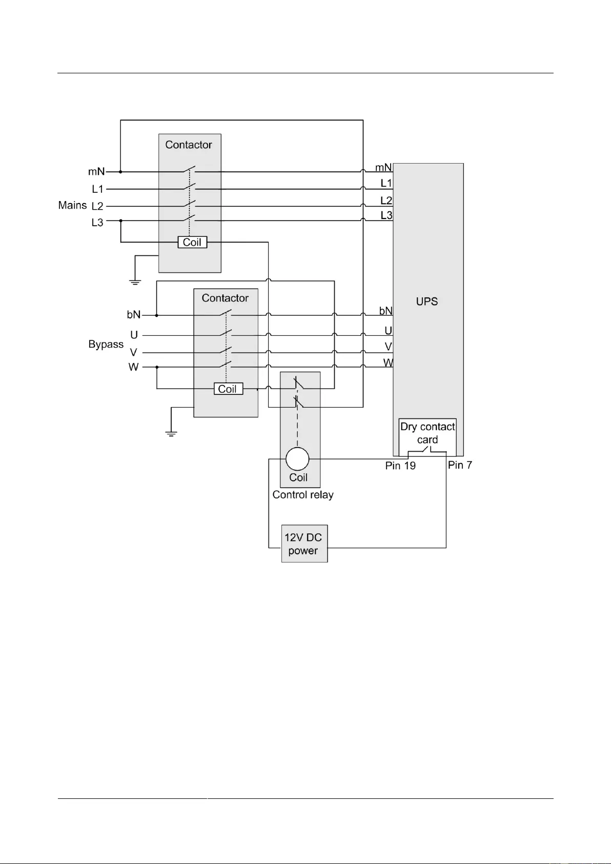
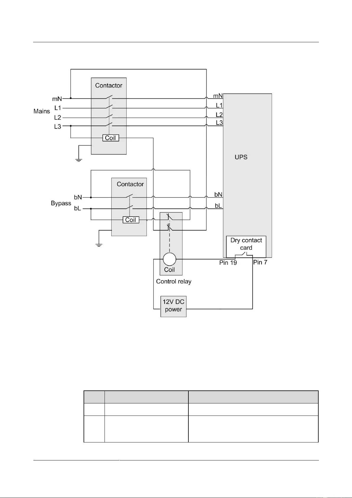
Figure 3-5, Figure 3-6, Figure 3-7 and Figure 3-8 show backfeed protection connections (with
dry contract control).
Figure 3-5 Bypass backfeed protection connections for the UPS2000—G-6 kVA/10 kVA/15
kVA/20 kVA (single-phase input single-phase output)
UPS2000-G-(6 kVA-20 kVA)
User Manual
Copyright © Huawei Technologies Co., Ltd.
Figure 3-6 Bypass backfeed protection connections for the UPS2000—G-10 kVA (three—phase
input single-phase output)
UPS2000-G-(6 kVA-20 kVA)
User Manual
Copyright © Huawei Technologies Co., Ltd.
Figure 3-7 Bypass backfeed protection connections for the UPS2000—G-15 kVA/20 kVA
(three-phase input three-phase output)
UPS2000-G-(6 kVA-20 kVA)
User Manual
Copyright © Huawei Technologies Co., Ltd.
Figure 3-8 Bypass backfeed protection connections for the UPS2000—G-15 kVA/20 kVA
(three-phase input single-phase output)
3.4 Check After Installation
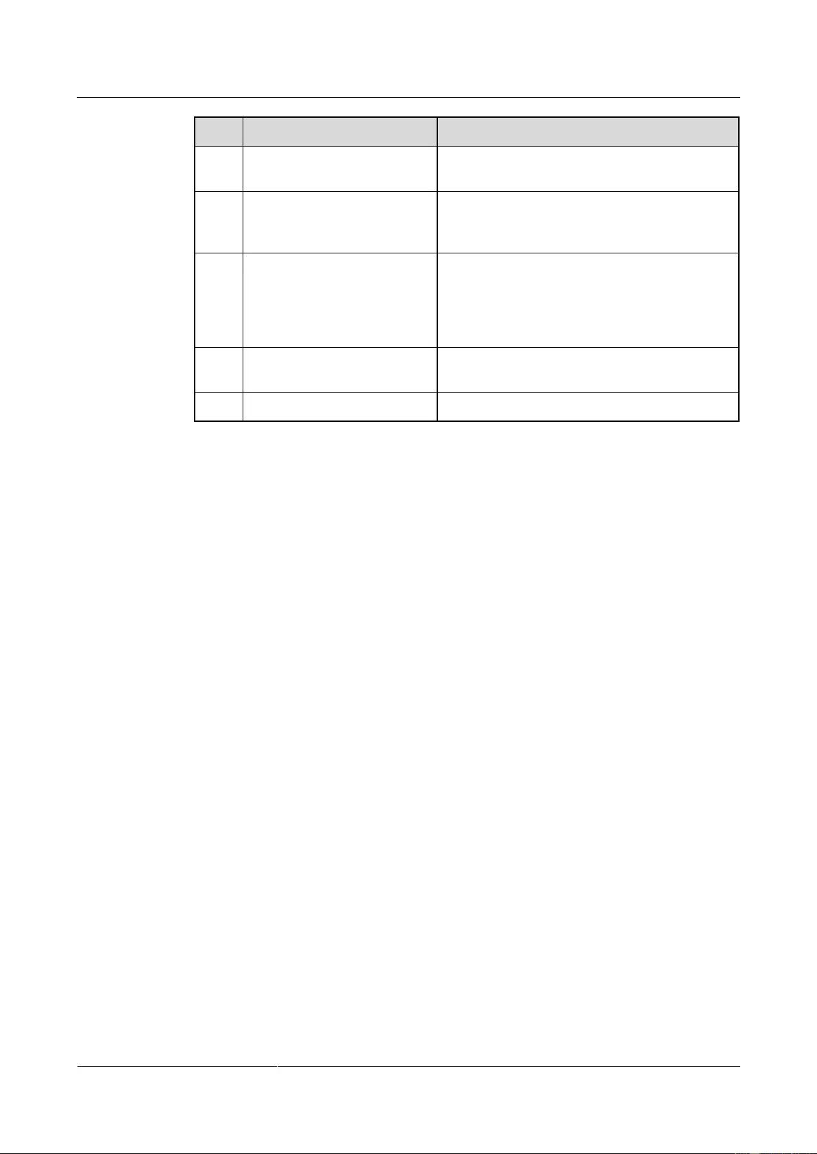
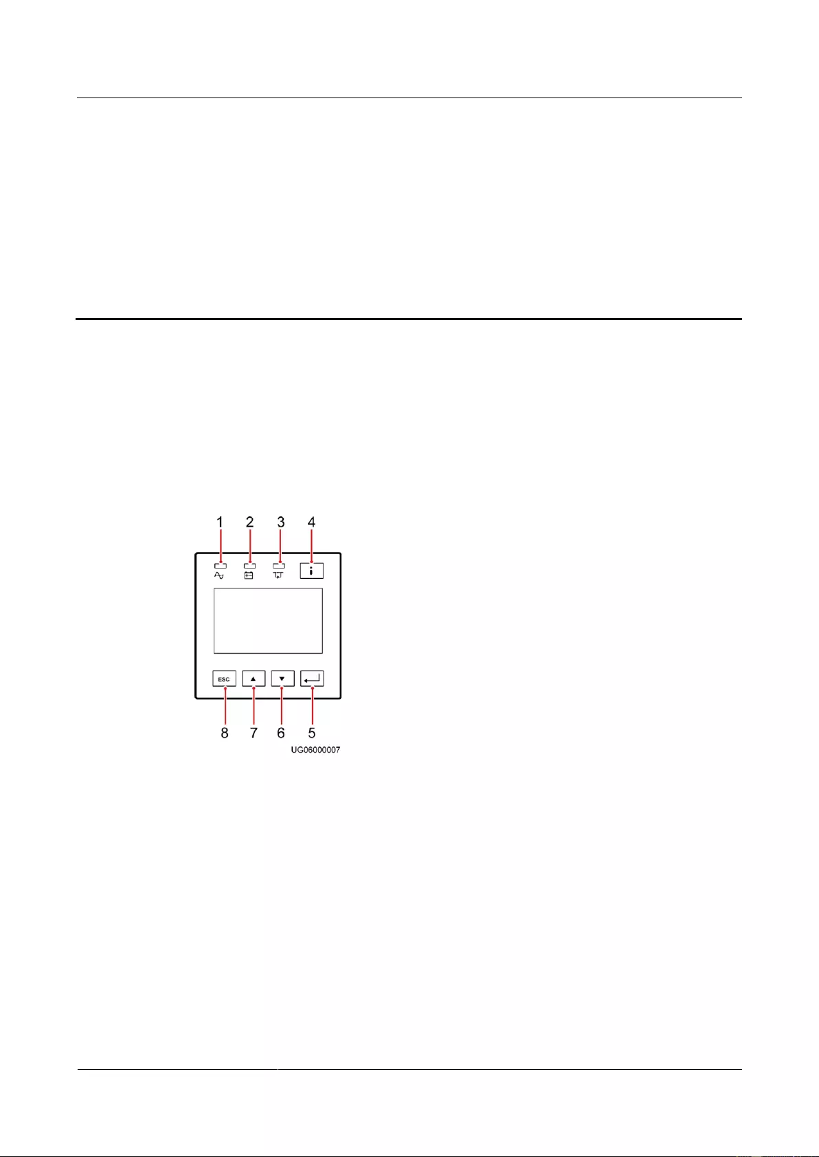
Table 3-5 lists the check items.
Table 3-5 Post—installation check items
Cable routing meets engineering requirements.
Input cables, output cables, and battery cables are
tightened to specified torques using a torque
wrench, connected correctly, and free of damage.
UPS2000-G-(6 kVA-20 kVA)
User Manual
Copyright © Huawei Technologies Co., Ltd.
Cable connections for USB
ports and network ports
Cables to USB ports and network ports are
connected correctly and securely.
Labels are neatly attached to both ends of each
cable, and the information on the labels is
concise and understandable.
The ground cable is securely connected to the
equipment room ground bar. Measure the
resistance between the UPS ground cable and the
equipment room ground bar, which must be less
than 0.1 ohm.
Distances between cable ties
Distances between cable ties are the same, and no
burr exists.
Clean the conductive air and other sundries.
UPS2000-G-(6 kVA-20 kVA)
User Manual
Copyright © Huawei Technologies Co., Ltd.
4 Control Panel
4.1 Introduction
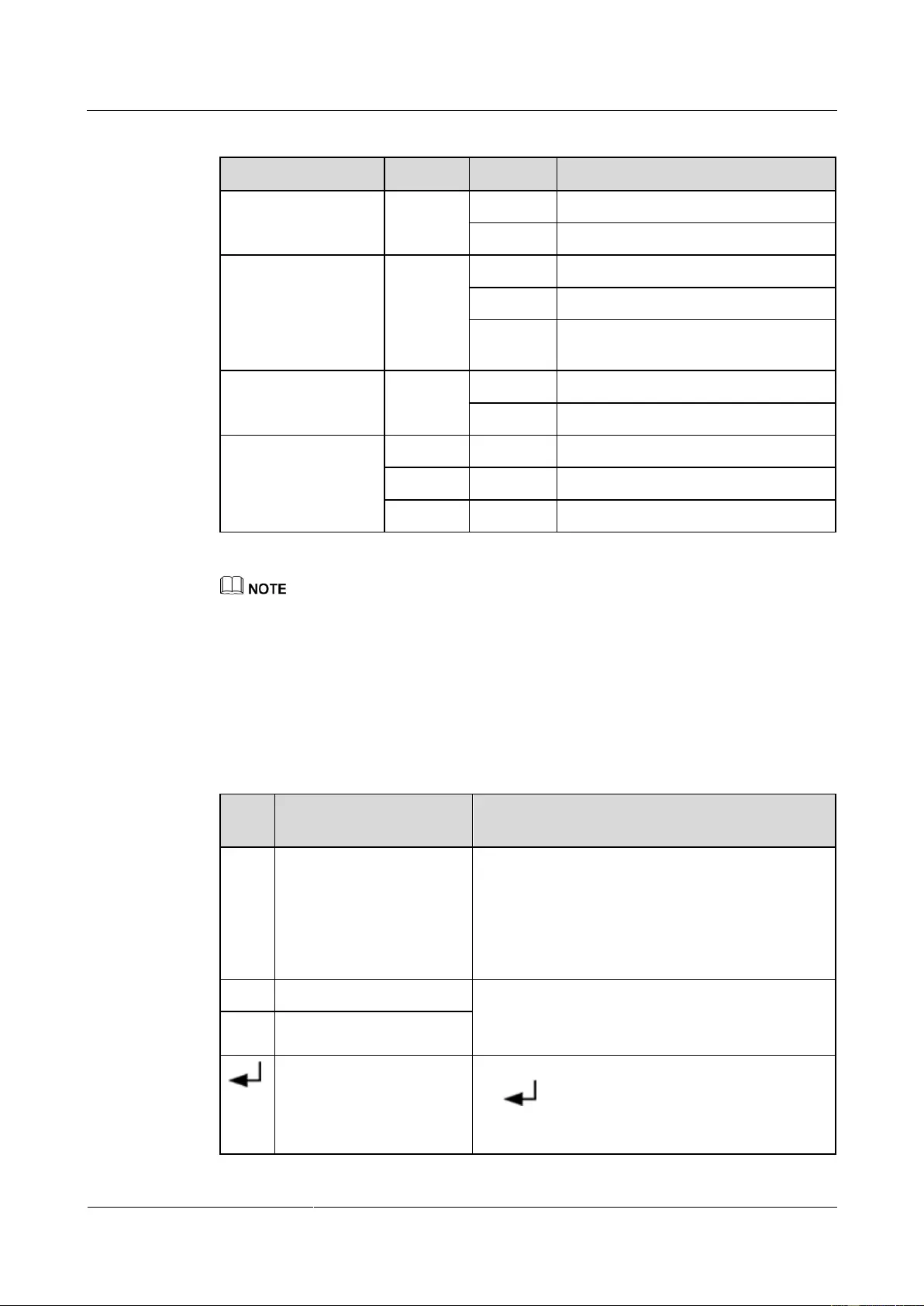
The control panel, located on the front panel of the UPS, controls UPS running, displays
running data, and allows you to set parameters and view alarms. Figure 4-1 shows the control
panel.
Figure 4-1 Control panel
(4) Fault
indicator/INFO button
(5) Startup/Enter/Battery
Self-Check/Mute button
4.2 Indicators
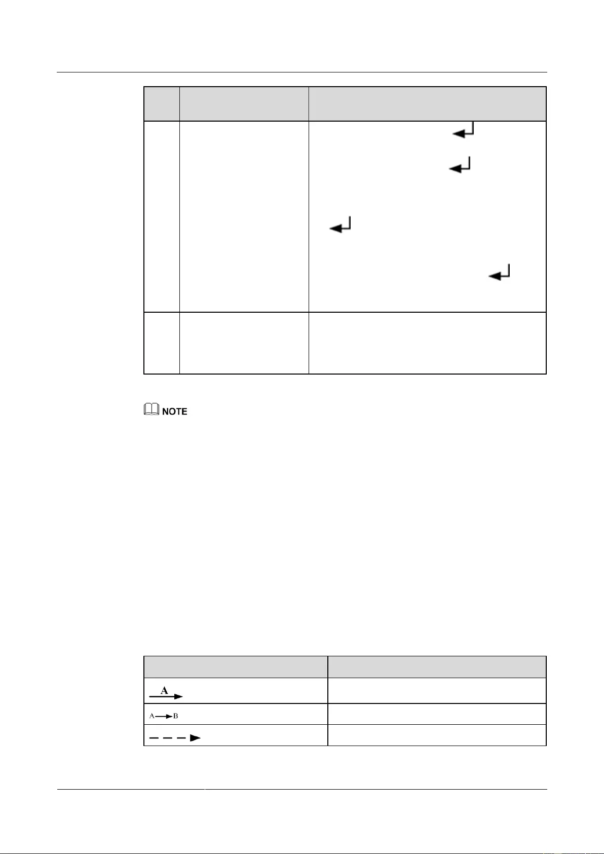
Table 4-1 describes the indicators on the control panel.
UPS2000-G-(6 kVA-20 kVA)
User Manual
Copyright © Huawei Technologies Co., Ltd.
Table 4-1 Indicator description
The UPS is in normal mode.
The UPS is not in normal mode.
The UPS is in battery mode.
The UPS is not in battery mode.
The remaining battery capacity is less
than 25%.
The UPS is in bypass mode.
The UPS is not in bypass mode.
Fault indicator/INFO
button
The UPS generates an alarm.
The UPS is running properly.
The UPS is in ECO mode when the mains indicator and bypass indicator are both on.
4.3 Functional Buttons
The control panel provides five buttons to start and shut down the UPS and set parameters.
Table 4-2 describes the buttons.
Table 4-2 Button description
On the default screen, press ESC for more than 5
seconds. Release the button when you hear a
beep sound. The inverter shuts down.
On any other screen, press ESC to return to the
upper-level menu (the default screen is the
upper-level screen for the main menu screen).
Press ▲ or ▼ to scroll upward or downward.
You can set a value by using the list or step increase
or decrease.
Enter/Startup/Battery
Self-Check/Mute
On the default screen in bypass mode, hold down
for more than 5 seconds. Release the
button when you hear a beep sound. The UPS
starts.
UPS2000-G-(6 kVA-20 kVA)
User Manual
Copyright © Huawei Technologies Co., Ltd.
On the default screen, press . The main
menu is displayed.
On any menu screen, press . The
lower-level menu is displayed. If the menu is the
last level, an information screen is displayed.
On the default screen in normal mode, hold down
for more than 5 seconds. Release the
button when you hear a beep sound. The battery
test starts.
When the buzzer buzzes, hold down for
2–5 seconds. The buzzer is muted when you
release the button.
Fault indicator/INFO
button
When an alarm is generated, press i to view the
active alarm information.
When no alarm is generated, press i to return to
the default screen.
Battery self-check: After the UPS starts in normal mode, it transfers to battery mode for 10 seconds
to check that the battery status (if no battery is connected, No battery is displayed) and that the UPS
can transfer to battery mode. The purpose is to prevent power backup failure when the UPS needs to
transfer to battery mode.
If you do not press any button within 60 seconds, the default screen is displayed.
4.4 LCD
The LCD displays the UPS running data and alarm information, and allows you to set
parameters and control operation. The backlight turns off if you do not press any button
within 30 seconds.
4.5 LCD Startup Screens
Table 4-3 Symbol conventions
Press B after you press A.
Indicates omitted screens.
UPS2000-G-(6 kVA-20 kVA)
User Manual
Copyright © Huawei Technologies Co., Ltd.
The symbol conventions apply to all chapters in this document.
The LCD figures in this document correspond to V100R001C10SPC802. The LCD
updated without notice. If the LCD is updated, contact Huawei for the latest LCD figures.
The screen in this document based on the UPS2000-G-15 kVA/20 kVA. The parameter
values in the menu pictures in this document are for reference only.
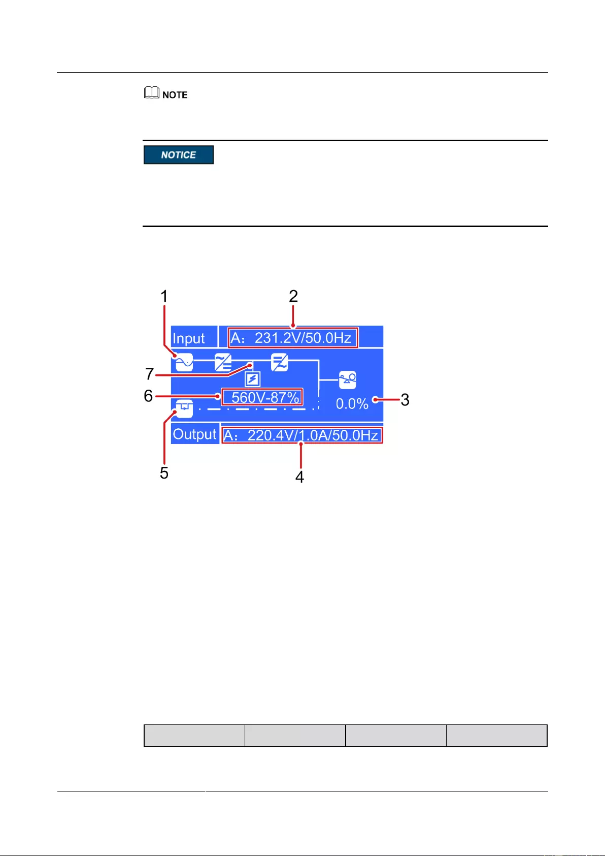
Figure 4-2 shows a startup screen.
Figure 4-2 Description of the startup screen
(1) Normal mode (The solid line indicates
normal mode. The dotted line indicates
non-normal mode.)
(2) Input voltage and frequency
(4) Output voltage, current, and frequency
(5) Bypass mode (The solid line indicates
bypass mode. The dotted line indicates
non-bypass mode.)
(6) Battery voltage and capacity displayed
during charge; Battery discharge time and
capacity displayed during discharge.
(7) Battery mode (The solid line indicates
battery in charge or discharge mode. The
dotted line indicates non-battery mode.)
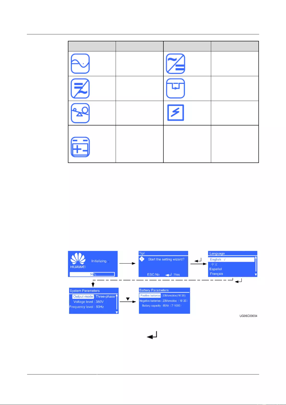
Table 4-4 describes the icons on the screen.
Table 4-4 Icons on the screen
UPS2000-G-(6 kVA-20 kVA)
User Manual
Copyright © Huawei Technologies Co., Ltd.
Rectifier/Power
factor correction
(PFC) working
4.5.1 Starting the UPS in Normal Mode
Initial Startup
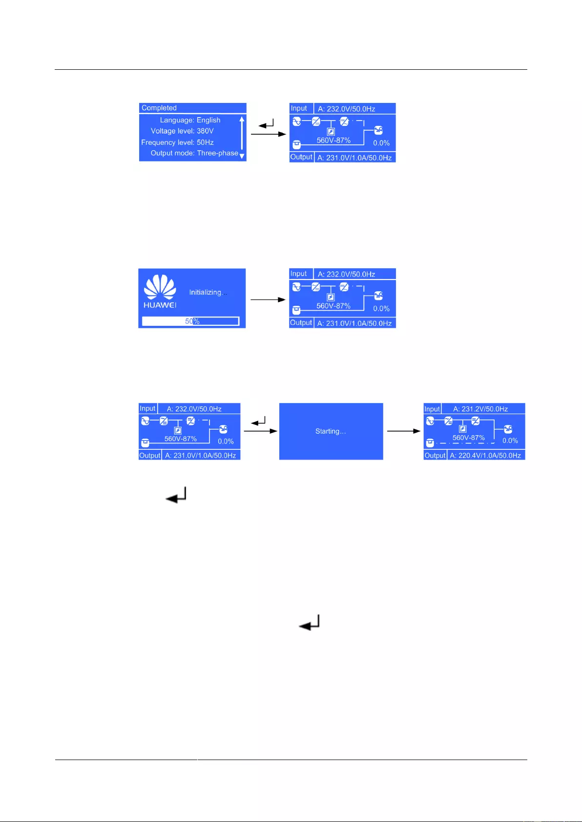
The settings wizard starts automatically when you start the UPS for the first time or when you
restart the UPS after restoring factory settings, as shown in Figure 4-3. The settings wizard
provides the Language, System Parameters, and Battery Parameters screens.
Figure 4-3 Settings wizard
After you complete the settings, press . The standby screen is displayed.
UPS2000-G-(6 kVA-20 kVA)
User Manual
Copyright © Huawei Technologies Co., Ltd.
Figure 4-4 Standby screen displayed after initial startup
Non-initial Startup
When the initialization is complete, the standby screen is displayed.
Figure 4-5 Standby screen displayed after non-initial startup
After the UPS starts, it enters normal mode.
Figure 4-6 Normal mode
Press . The main menu screen is displayed.
4.5.2 Starting the UPS in Battery Mode
Initial Startup
The settings wizard starts automatically when you start the UPS for the first time or when you
restart the UPS after restoring factory settings. The settings wizard provides the Language,
System Parameters, and Battery Parameters screens.
After you complete the settings, press . The standby screen is displayed.
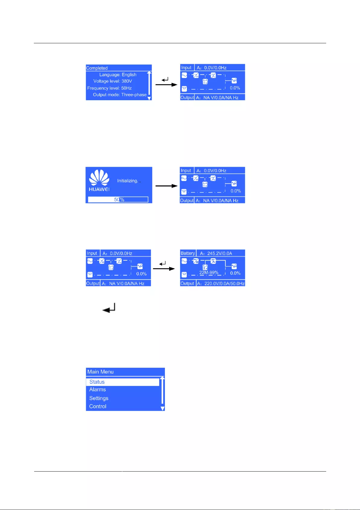
UPS2000-G-(6 kVA-20 kVA)
User Manual
Copyright © Huawei Technologies Co., Ltd.
Figure 4-7 Standby screen displayed after initial startup
Non-initial Startup
When the initialization is complete, the standby screen is displayed.
Figure 4-8 Standby screen displayed after non-initial startup
After the UPS starts, it enters battery mode.
Figure 4-9 Battery mode
Press . The main menu screen is displayed.
4.6 LCD Menu Hierarchy
Figure 4—10 Main Menu screen
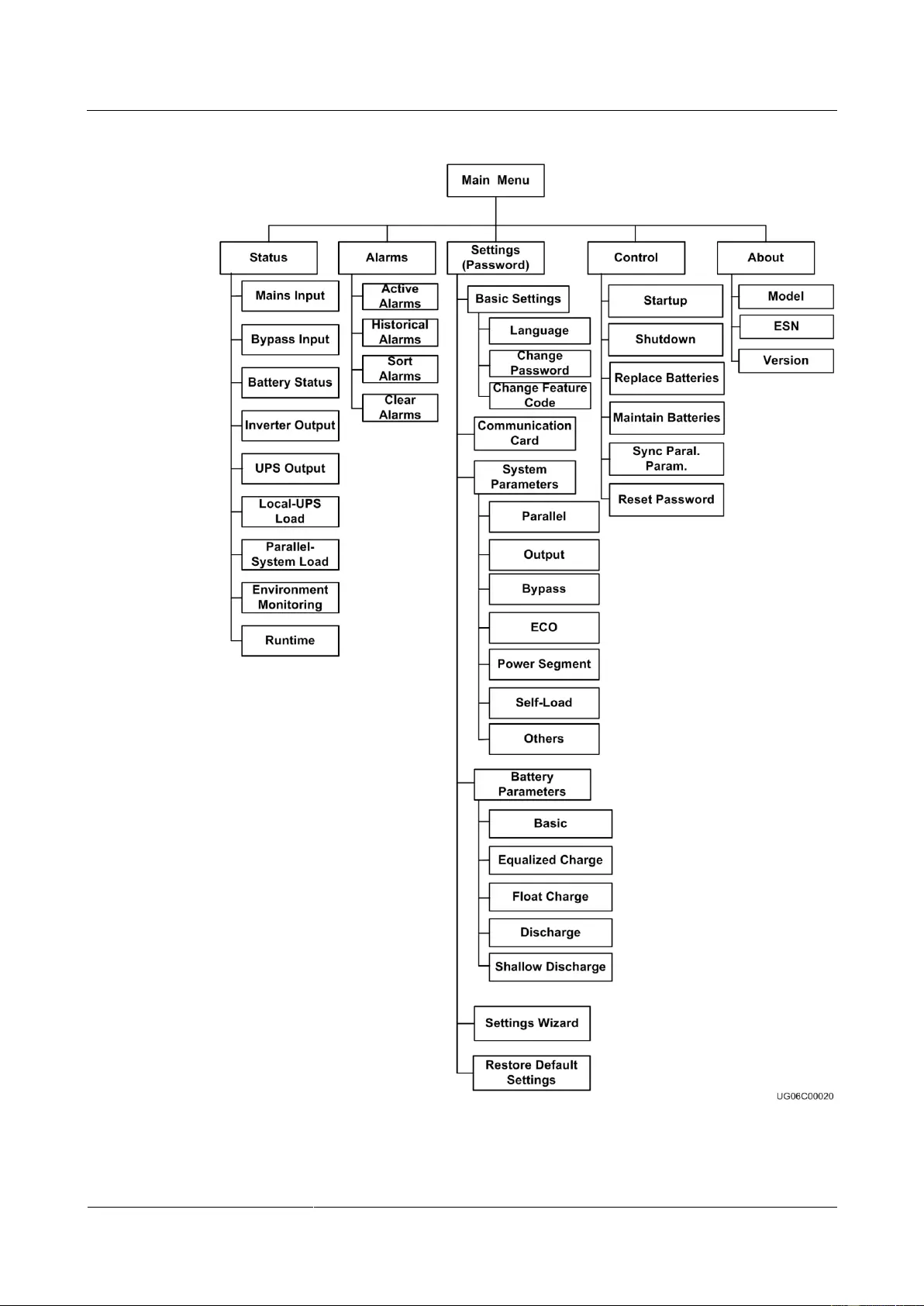
Figure 4-11 shows the LCD menu hierarchy.
UPS2000-G-(6 kVA-20 kVA)
User Manual
Copyright © Huawei Technologies Co., Ltd.
Figure 4—11 LCD menu hierarchy
UPS2000-G-(6 kVA-20 kVA)
User Manual
Copyright © Huawei Technologies Co., Ltd.
4.6.1 Status Screen
On the Main Menu screen, select Status, and press . The Status screen is displayed.
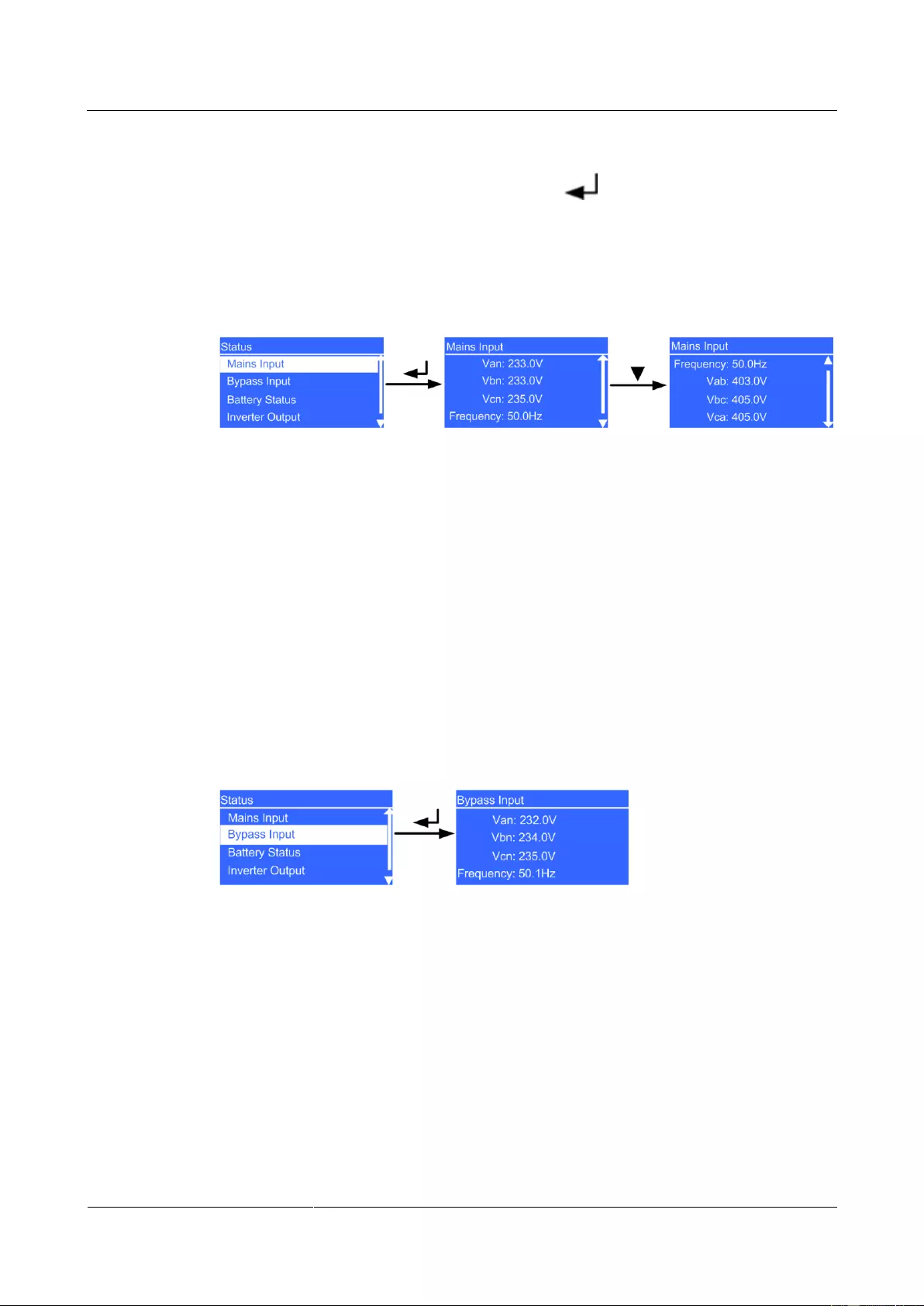
Mains Input Screen
Figure 4-12 shows the Mains Input screen.
Figure 4—12 Mains Input screen
Van, Vbn, and Vcn parameters
Phase voltages displayed on the Mains Input screen (The parameter is Voltage in the
case of single-phase input.)
Frequency parameter
Frequency displayed on the Mains Input screen.
Vab, Vbc, and Vca parameters
Line voltages displayed on the Mains Input screen (The parameters are not displayed in
the case of single-phase input.)
Bypass Input Screen
Figure 4-13 shows the Bypass Input screen.
Figure 4—13 Bypass Input screen
Van, Vbn, and Vcn parameters
Phase voltages displayed on the Bypass Input screen (The parameter is Voltage in the
case of single-phase input.)
Frequency parameter
Frequency displayed on the Bypass Input screen.
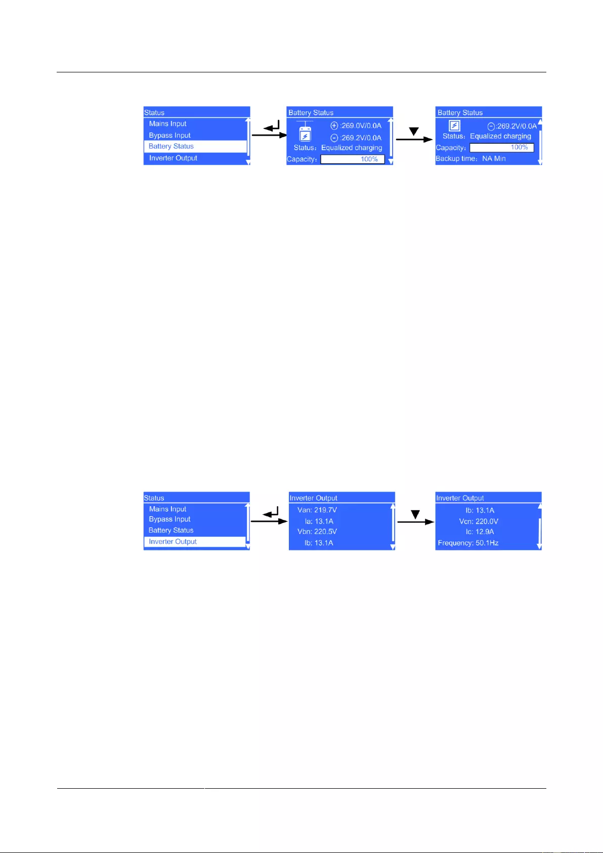
Battery Status Screen
Figure 4-14 shows the Battery Status screen.
UPS2000-G-(6 kVA-20 kVA)
User Manual
Copyright © Huawei Technologies Co., Ltd.
Figure 4—14 Battery Status screen
Battery voltage parameter
Battery string voltage (positive and negative battery string voltages in the case of the
UPS2000-G-15 kVA/20 kVA)
Battery current parameter
Battery string current (positive and negative battery string currents in the case of the
UPS2000-G-15 kVA/20 kVA). + is displayed during battery charge, and – is displayed
during battery discharge.
Status parameter
The battery status is NA (battery not connected or reversely connected), Equalized
charging, Float charging, Hibernating, or Discharging.
Capacity parameter
Remaining battery capacity
Backup time parameter
Estimated backup time. The value is NA during battery charge.
Inverter Output Screen
Figure 4-15 shows the Inverter Output screen.
Figure 4—15 Inverter Output screen
Van, Vbn, and Vcn parameters
Phase voltages displayed on the Inverter Output screen (The parameter is Voltage in
the case of single-phase input.)
la, lb, and lc parameters
Phase currents displayed on the Inverter Output screen (The parameter is Current in
the case of single-phase input.)
Frequency parameter
Frequency displayed on the Inverter Output screen.
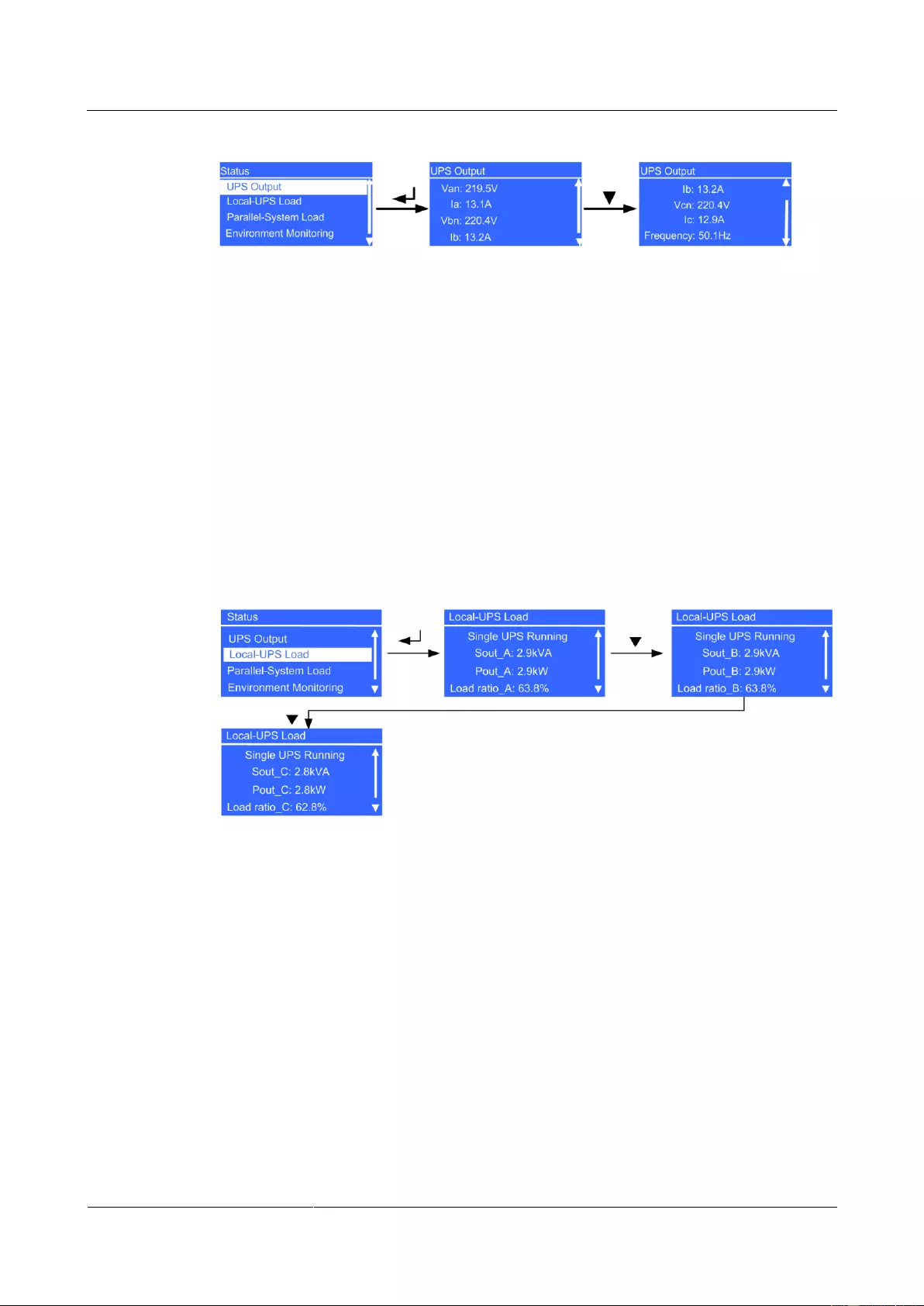
UPS Output Screen
Figure 4-16 shows the UPS Output screen.
UPS2000-G-(6 kVA-20 kVA)
User Manual
Copyright © Huawei Technologies Co., Ltd.
Figure 4—16 UPS Output screen
Van, Vbn, and Vcn parameters
Phase voltages displayed on the UPS Output screen (The parameter is Voltage in the
case of single-phase input.)
la, lb, and lc parameters
Phase currents displayed on the UPS Output screen (The parameter is Current in the
case of single-phase input.)
Frequency parameter
Frequency on displayed the UPS Output screen.
Local-UPS Load Screen
Figure 4-17 shows the Local-UPS Load screen.
Figure 4—17 Local—UPS Load screen
Single UPS Running screen
A single UPS is running.
Sout_A, Sout_ B, and Sout_C parameters
Phase A, B, and C apparent power displayed on the Local-UPS Load screen (The
parameter is Sout in the case of single-phase input.)
Pout_A, Pout_ B, and Pout_C parameters
Phase A, B, and C active power displayed on the Local-UPS Load screen (The
parameter is Pout in the case of single-phase input.)
Load ratio_A, Load ratio_B, and Load ratio_C parameters
Phase A, B, and C load ratio displayed on the Local-UPS Load screen (the parameter is
Load ratio in the case of single-phase input.)
UPS2000-G-(6 kVA-20 kVA)
User Manual
Copyright © Huawei Technologies Co., Ltd.
Parallel-System Load Screen
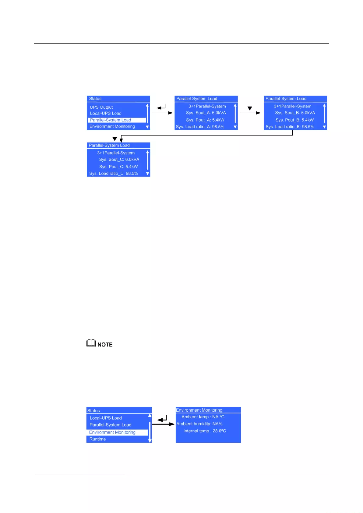
Figure 4-18 shows the Parallel-System Load screen.
Figure 4—18 Parallel—System Load screen
N+X Parallel-System screen
A parallel system is running. X (value range: 0–3) indicates the number of redundant
UPSs (configurable on the LCD); N (value range: 1–4) indicates the number of requisite
UPSs (total number of UPSs minus X). The total number of UPSs is automatically
identified by the system.
Sys. Sout_A, Sys. Sout_ B, and Sys. Sout_C parameters
System phase A, B, and C apparent power displayed on the Parallel-System Load
screen. The parameter is Sys. Sout in the case of single-phase input; the parameters are
not displayed in single UPS mode.
Sys. Pout_A, Sys. Pout_ B, and Sys. Pout_C parameters
System phase A, B, and C active power displayed on the Parallel-System Load screen.
The parameter is Sys. Pout in the case of single-phase input; the parameters are not
displayed in single UPS mode.
Sys. Load ratio_A, Sys. Load ratio_B, and Sys. Load ratio_C parameters
System phase A, B, and C load ratio displayed on the Parallel-System Load screen. The
parameter is Sys. Load ratio in the case of single-phase input, and the parameters are
not displayed in single UPS mode.
System information is not displayed in single UPS mode.
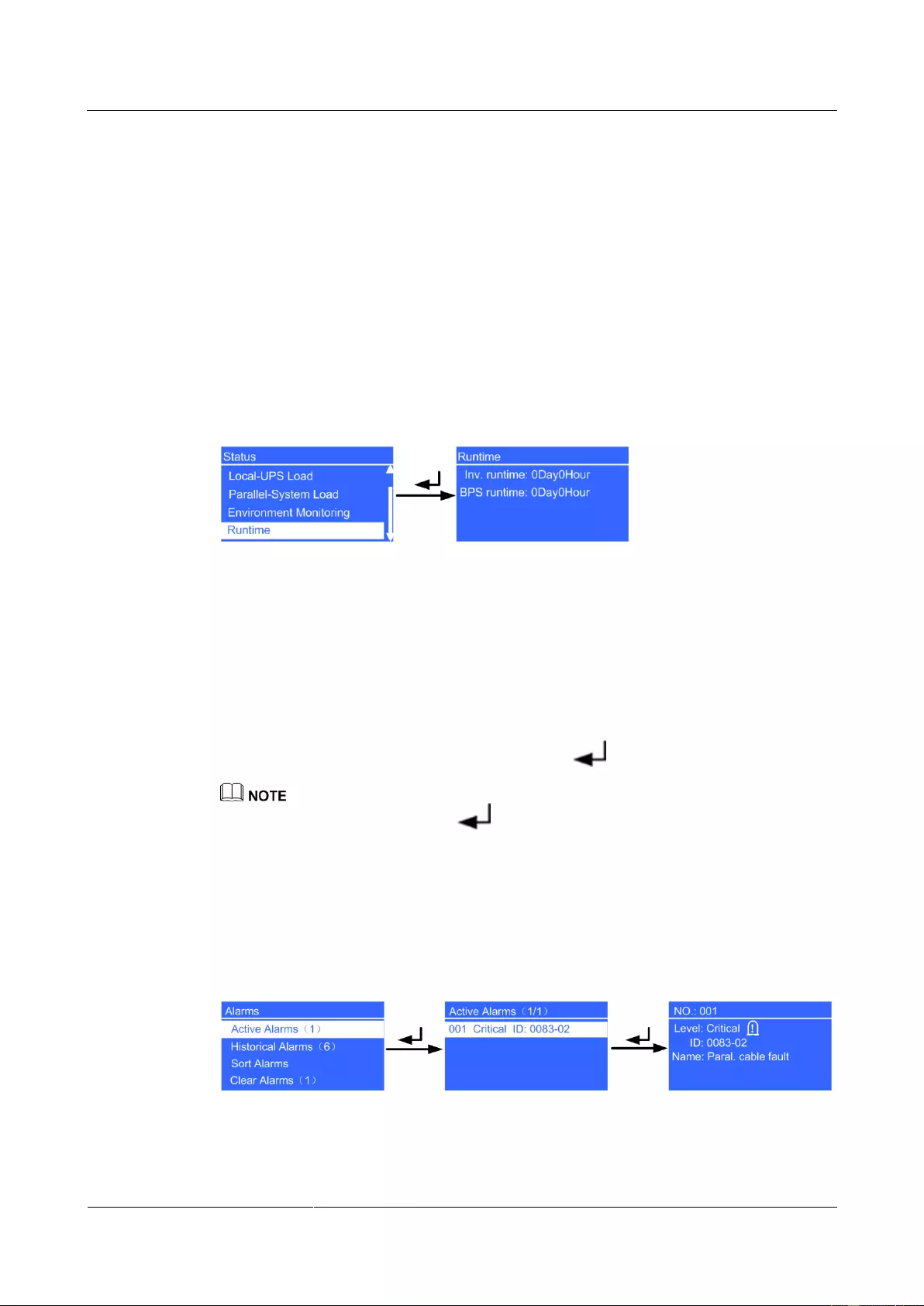
Environment Monitoring Screen
Figure 4-19 shows the Environment Monitoring screen.
Figure 4—19 Environment Monitoring screen
UPS2000-G-(6 kVA-20 kVA)
User Manual
Copyright © Huawei Technologies Co., Ltd.
Ambient temp. parameter
Temperature detected by the ambient temperature and humidity sensor (used together
with an SNMP card; if the sensor is not connected, NA is displayed.)
Ambient humidity parameter
Temperature and humidity sensor humidity (Install an SNMP card and a temperature and
humidity sensor; if they are not installed, NA is displayed.)
Internal temp. parameter
Temperature in the UPS cabinet
Runtime Screen
Figure 4-20 shows the Runtime screen.
Figure 4—20 Runtime screen
Inv. runtime parameter
Time during which the UPS runs in inverter output state
BPS runtime parameter
UPS bypass running duration
4.6.2 Alarms Screen
On the Main Menu screen, select Alarms, and press . The Alarms screen is displayed.
When the buzzer buzzes, hold down for 2–5 seconds to mute it. The buzzer is muted when you
release the button. When the buzzer is mute, it can not be buzzes again, until a new alarm is generated.
Active Alarms Screen
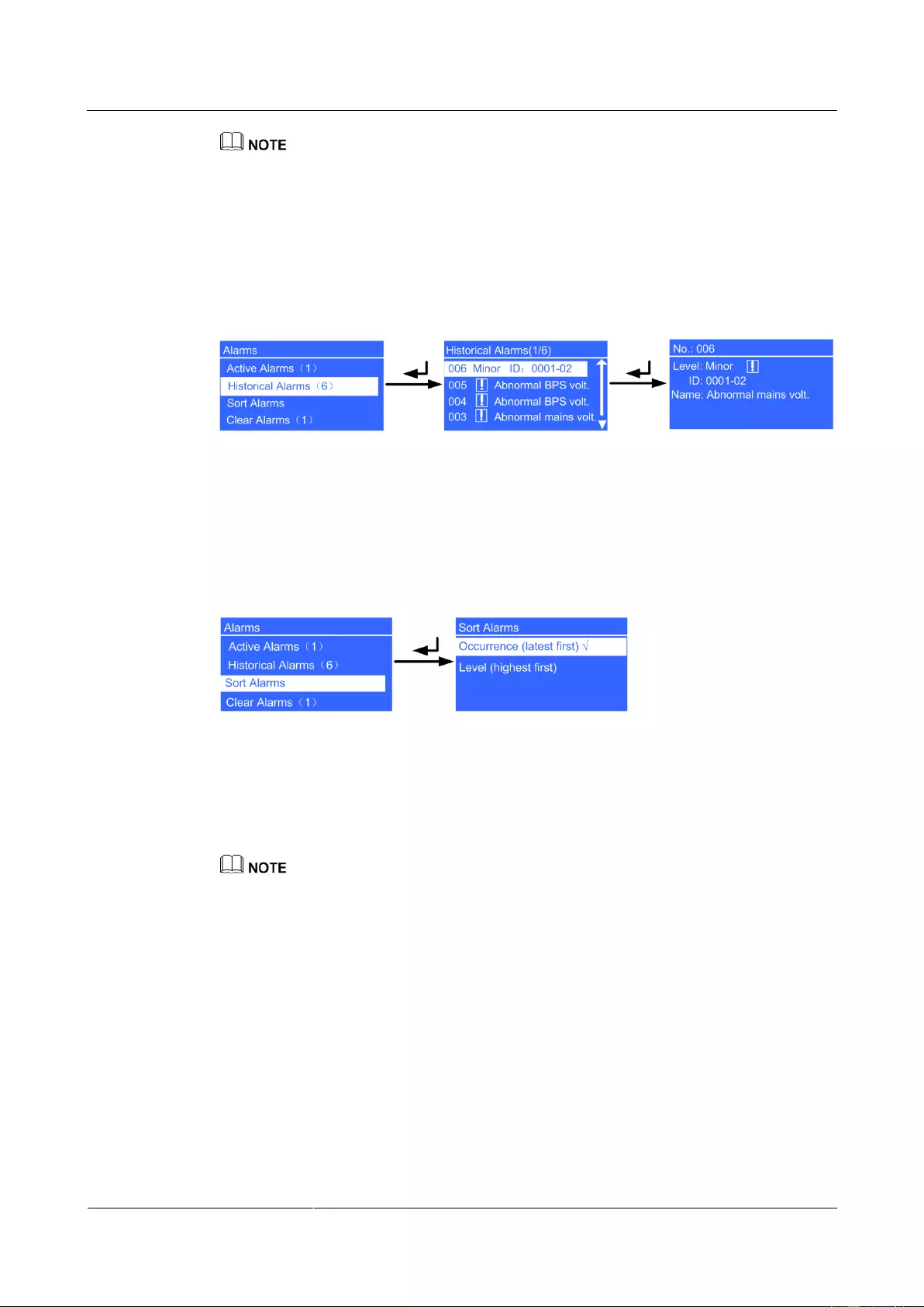
The Active Alarms screen displays the active alarm information, such as the alarm serial
number, severity, ID, and name, as shown in Figure 4-21.
Figure 4—21 Active Alarms screen
UPS2000-G-(6 kVA-20 kVA)
User Manual
Copyright © Huawei Technologies Co., Ltd.
If an alarm is generated, press the INFO button on the default screen. On the Active Alarms screen,
view the active alarms.
Historical Alarms Screen
The Historical Alarms screen displays the historical alarm information, such as the alarm
serial number, severity, ID, and name, as shown in Figure 4-22.
Figure 4—22 Historical Alarms screen
Sort Alarms Screen
The Sort Alarms screen allows you to view alarms by occurrence time or severity, as shown
in Figure 4-23.
Figure 4—23 Sort Alarms screen
Occurrence (latest first) parameter
Alarms are sorted by occurrence time. The latest alarms are listed first.
Level (highest first) parameter
Active alarms are displayed by severity. The most critical alarms are listed first.
√ is displayed next to a selected Sort Alarms.
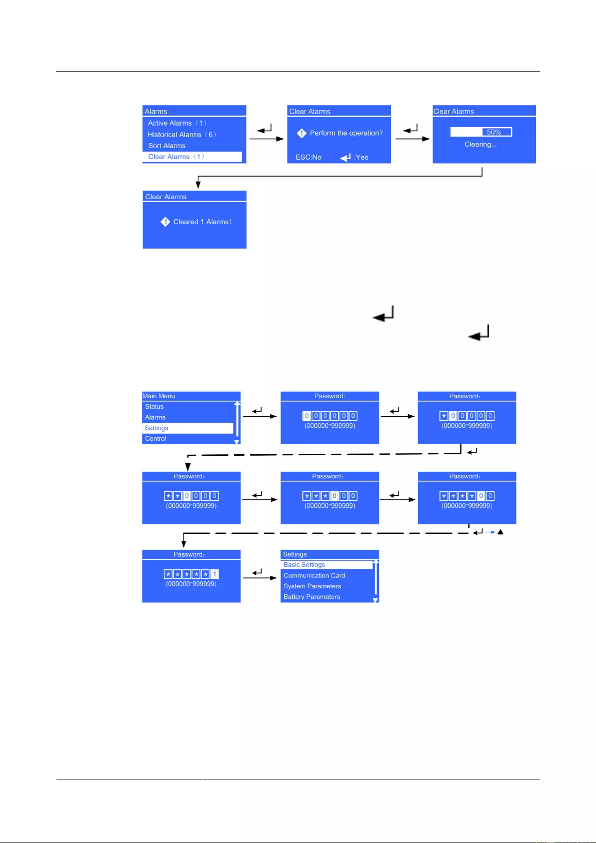
Clear Alarms Screen
Clear the alarms that you can clear manually, as shown in Figure 4-24.
UPS2000-G-(6 kVA-20 kVA)
User Manual
Copyright © Huawei Technologies Co., Ltd.
Figure 4—24 Clear Alarms screen
4.6.3 Settings Screen
On the Main Menu screen, select Settings, and press . The Settings login screen is
displayed. The preset password is 000001. After you enter a password, press . The
Settings screen is displayed, as shown in Figure 4-25.
Figure 4—25 Settings screen
UPS2000-G-(6 kVA-20 kVA)
User Manual
Copyright © Huawei Technologies Co., Ltd.
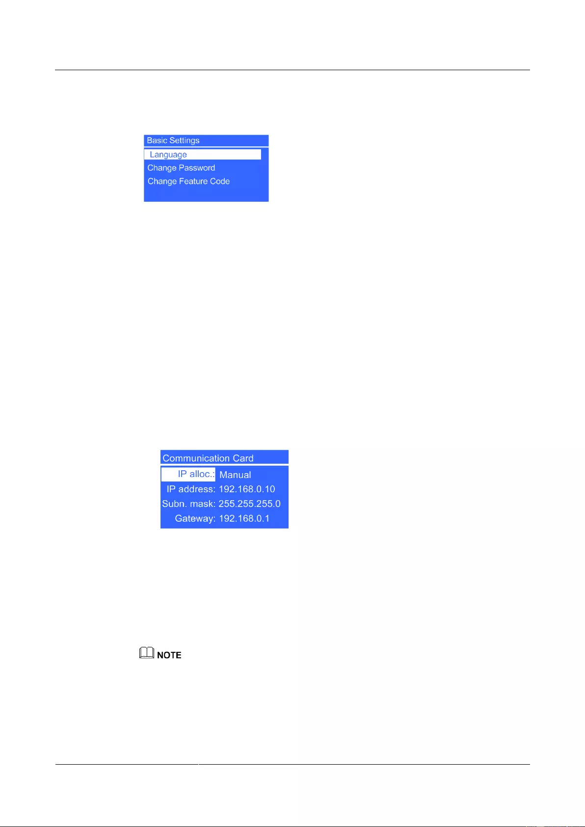
Basic Settings Screen
Figure 4—26 Basic Settings screen
Language parameter
You can select Chinese, English (preset), Turkish, French, and Russian.
Change Password parameter
You can change the password by choosing Settings > Basic Settings > Change
Password. The preset password is 000001. The password allows you to enter the
Settings screen.
Change Feature Code parameter
You can change the feature code by choosing Settings > Basic Settings > Change
Feature Code. The preset feature code is 999999. The feature code is used to restore the
preset password.
Communication Card Screen
1. If an SNMP card is connected, set the following parameters:
Figure 4—27 SNMP card settings
− IP alloc. parameter
Specifies the DHCP address allocating mode. The options include Manual and
Automatic. The default value is Manual. After the allocating mode is set to
Automatic, an Allocating dialog box is displayed on the screen. If allocation
succeeds, the new IP address is displayed. If allocation fails, the IP address restores
to the default one: 192.168.0.10. If the allocating mode is set to Automatic, you can
only query the IP address but cannot set the IP address manually.
If the UPS monitor does not support the DHCP function, after the DHCP is selected for the SNMP card,
you cannot set the IP address of the SNMP card on the UPS monitor. You are advised to update the
version of the UPS monitor.
− IP address parameter
Set an IP address for the SNMP card. The value ranges from 1.0.0.0 to
223.255.255.255. The default value is 192.168.0.10.
UPS2000-G-(6 kVA-20 kVA)
User Manual
Copyright © Huawei Technologies Co., Ltd.
− Subn. mask parameter
Set a subnet mask for the SNMP card. The value ranges from 0.0.0.0 to
255.255.255.255. The default value is 255.255.255.0.
− Gateway parameter
Set a gateway address for the SNMP card. The value ranges from 1.0.0.0 to
223.255.255.255. The default value is 192.168.0.1.
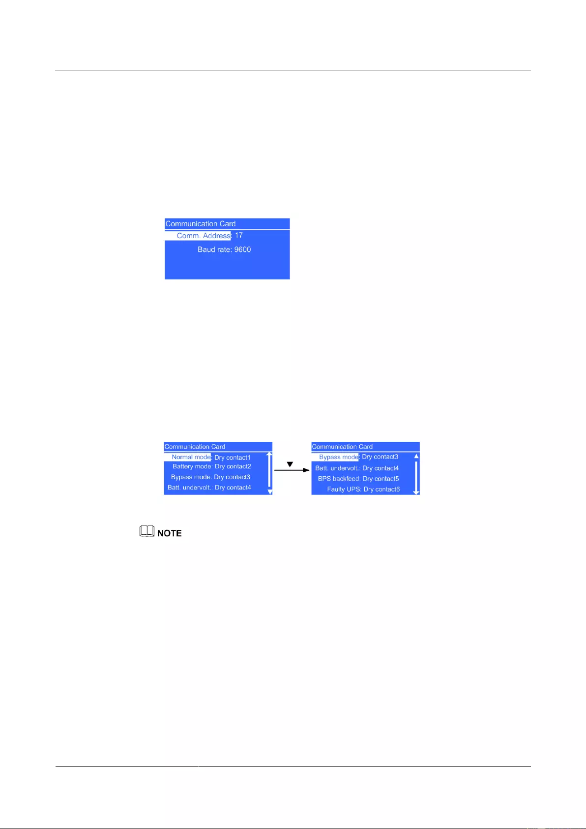
2. If a Modbus card is connected, the following parameters are displayed:
Figure 4—28 Modbus card settings
− Comm. address parameter
Set a communications address for the Modbus card over the dual in-line package
(DIP) switch on the Modbus card. The value cannot be changed on the LCD.
− Baud rate parameter
Set a baud rate for the Modbus card over the DIP switch on the Modbus card. The
value cannot be changed on the LCD.
3. If a dry contact card is connected, set the following parameters:
Figure 4—29 Dry contact card settings
Multiple statuses can be associated with one dry contact, but one status cannot be associated with
multiple dry contacts.
− Normal mode parameter
Set the output dry contact associated with normal mode. When the UPS is in normal
or ECO mode, this dry contact is enabled. The value ranges from Dry contact1 to
Dry contact6. The default value is Dry contact1.
− Battery mode parameter
Set the output dry contact associated with battery mode. When the UPS is in battery
or ECO mode, this dry contact is enabled. The value ranges from Dry contact1 to
Dry contact6. The default value is Dry contact2.
− Bypass mode parameter
Set the output dry contact associated with bypass mode. When the UPS is in bypass
or ECO mode, this dry contact is enabled. The value ranges from Dry contact1 to
Dry contact6. The default value is Dry contact3.
− Batt. undervolt parameter
UPS2000-G-(6 kVA-20 kVA)
User Manual
Copyright © Huawei Technologies Co., Ltd.
Set the output dry contact associated with low battery voltages. When the system
battery voltage is low, this dry contact is enabled. The value ranges from Dry
contact1 to Dry contact6. The default value is Dry contact4.
− BPS backfeed parameter
Set the output dry contact associated with bypass backfeed. When a bypass
backfeed alarm is generated, this dry contact is enabled. The value ranges from Dry
contact1 to Dry contact6. The default value is Dry contact5.
− Faulty UPS parameter
Set the output dry contact associated with UPS faults. When a critical alarm is
generated, this dry contact is enabled. The value ranges from Dry contact1 to Dry
contact6. The default value is Dry contact6.
System Parameters Screen
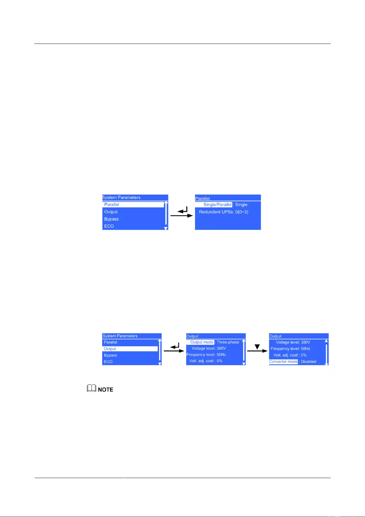
Parallel screen
Figure 4—30 Parallel screen
− Single/Parallel parameter
The values include Single and Parallel. The default value is Single. The parameter
is configurable after the inverter shuts down.
− Redundant UPSs parameter
Set the number of redundant UPSs. The value ranges from 0 to 3. The default value
is 0. The parameter is configurable after the inverter shuts down.
Output screen
Figure 4—31 Output screen
The UPS supports 208 V output. In the case of 208 V output, the power is derated to 90%. For cable
configurations and connections, see the details about 220 V output.
− Output mode parameter
Set the system output mode. The value is not configurable on the UPS2000-G-6
kVA/10 kVA. The default value is Single-phase. The parameter is configurable on
the UPS2000-G-15 kVA/20 kVA. The values include Single-phase and
Three-phase. The default value is Three-phase. The input mode is identified
automatically by the system. The parameter is configurable after the inverter shuts
down.
UPS2000-G-(6 kVA-20 kVA)
User Manual
Copyright © Huawei Technologies Co., Ltd.
− Voltage level parameter
Set the system output voltage level. The values include 220 V (default), 230 V, and
240 V on the UPS2000-G-6 kVA/10 kVA. The values include 220 V (default), 230
V, and 240 V on the UPS2000-G-15 kVA/20 kVA (single-phase output). The values
include 380 V (default), 400 V, and 415 V on the UPS2000-G-15 kVA/20 kVA
(three-phase output). After you change the voltage level, the upper thresholds for
bypass voltages restore to default values 15%. The parameter is configurable after
the inverter shuts down.
− Frequency level parameter
Set the system output frequency level. The values include 50 Hz (default), 60 Hz,
and Automatic. If the value is Automatic, the power-on bypass frequency ranges
from 40 Hz to 55 Hz, and the system output frequency is 50 Hz; if the power-on
bypass frequency ranges from 55 Hz to 70 Hz (excluding 55 Hz), and the system
output frequency is 60 Hz. The parameter is configurable after the inverter shuts
down.
− Volt. adj. coef. parameter
You can adjust the inverter rated output voltage. The values include ±5%, ±4%,
±3%, ±2%, ±1%, and 0% (default). Press + or – to increase or decrease the output
voltage. The parameter is configurable after the inverter shuts down.
If you set Converter mode to Enabled, the UPS cannot transfer to bypass mode or
maintenance bypass mode. If you shut down the inverter, the loads power off.
− Converter mode parameter
Determine whether to enable inverter mode. The values include Disabled and
Enabled. The default value is Disabled. In converter mode, the output voltage and
frequency are fixed at the specified values. The parameter is configurable after the
inverter shuts down.
Bypass screen
Figure 4—32 Bypass screen
− Max. voltage parameter
Upper threshold for the bypass voltage. If the difference between the bypass voltage
and the rated output voltage exceeds this value, the system determines that the
bypass voltage is abnormal and that the bypass is unavailable.
The Max. voltage parameter is associated with the system voltage level. The
default value is 15%.
If the voltage system is 220 V (380 V in the case of three-phase outputs), the values
include 10%, 15%, 20%, and 25%.
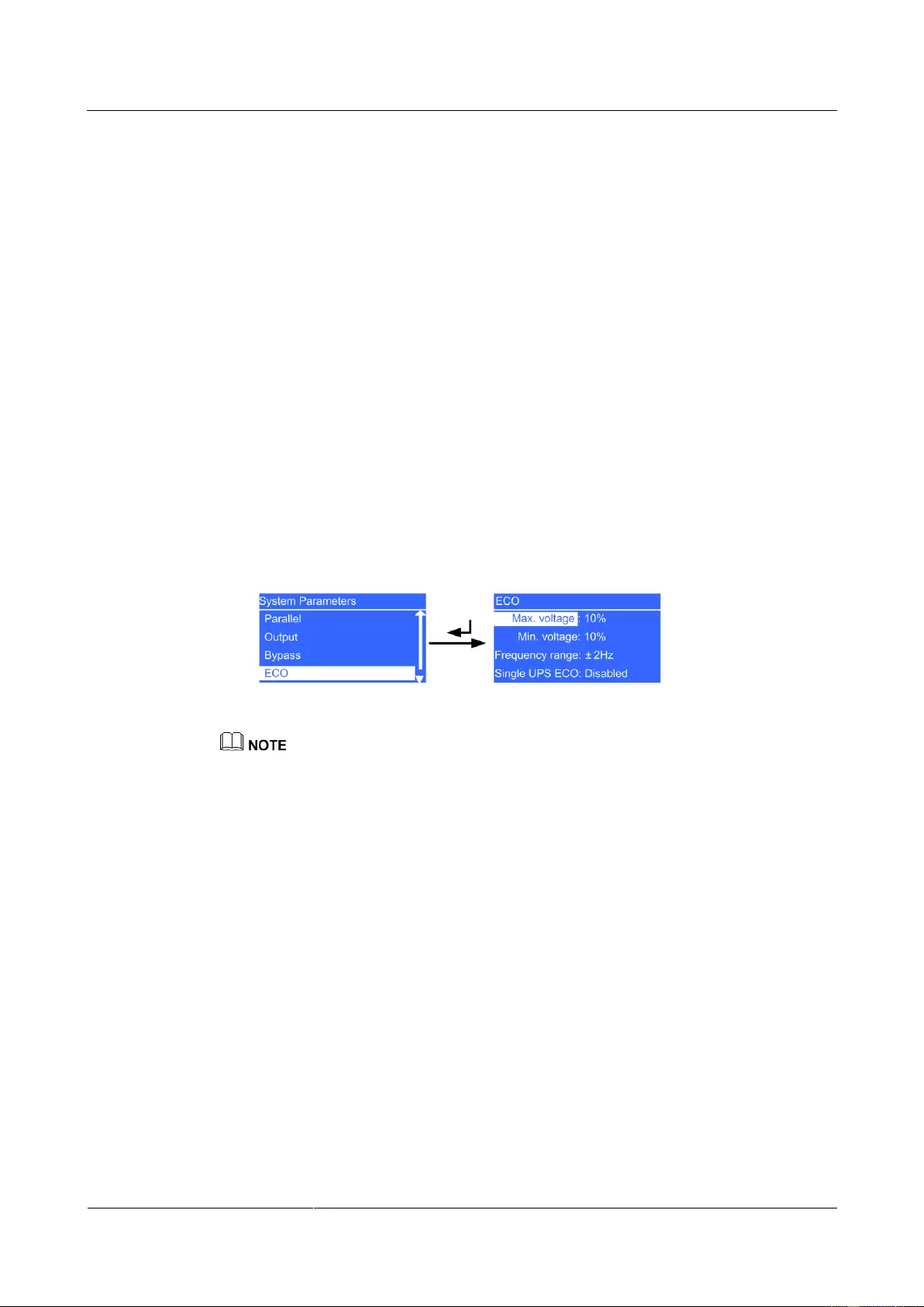
UPS2000-G-(6 kVA-20 kVA)
User Manual
Copyright © Huawei Technologies Co., Ltd.
If the voltage system is 230 V (400 V in the case of three-phase outputs), the values
include 10%, 15%, and 20%.
If the voltage system is 240 V (415 V in the case of three-phase outputs), the values
include 10% and 15%.
The parameter is configurable after the inverter shuts down.
− Min. voltage parameter
Lower threshold for the bypass voltage. If the difference between the bypass
voltage and the rated output voltage exceeds this value, the system determines that
the bypass voltage is abnormal and that the bypass is unavailable. The values
include 10%, 20% (default), 30%, 40%, 50%, and 60%. The parameter is
configurable after the inverter shuts down.
− Frequency range parameter
Bypass frequency range. When the difference between the bypass input frequency
and the rated frequency is greater than this value, the system determines that the
bypass frequency is abnormal and that the bypass is unavailable.
The frequency range must be greater than the ECO frequency range. The values
include ±0.5 Hz, ±1 Hz, ±2 Hz (default), ±3 Hz, ±4 Hz, ±5 Hz, and ±6 Hz. The
parameter is configurable after the inverter shuts down.
ECO screen
Figure 4—33 ECO screen
You can use the ECO function only if power grid conditions are good and the voltage and frequency
fluctuation is within the specified ECO voltage and frequency range.
− Max. voltage parameter
Upper threshold for the ECO voltage. In ECO mode, when the difference between
the bypass voltage and the rated voltage is greater than this value, the system
determines that the ECO voltage is abnormal and transfers to normal mode. The
values include 5%, 6%, 7%, 8%, 9%, and 10% (default). The parameter is
configurable after the inverter shuts down.
− Min. voltage parameter
Lower threshold for the ECO voltage. In ECO mode, when the difference between
the bypass voltage and the rated voltage is greater than this value, the system
determines that the ECO voltage is abnormal and transfers to normal mode. The
values include 5%, 6%, 7%, 8%, 9%, and 10% (default). The parameter is
configurable after the inverter shuts down.
− Frequency range parameter
ECO frequency range. In ECO mode, when the difference between the bypass
frequency and the rated frequency is greater than this range, the system determines
that the ECO frequency is abnormal and transfers to normal mode.
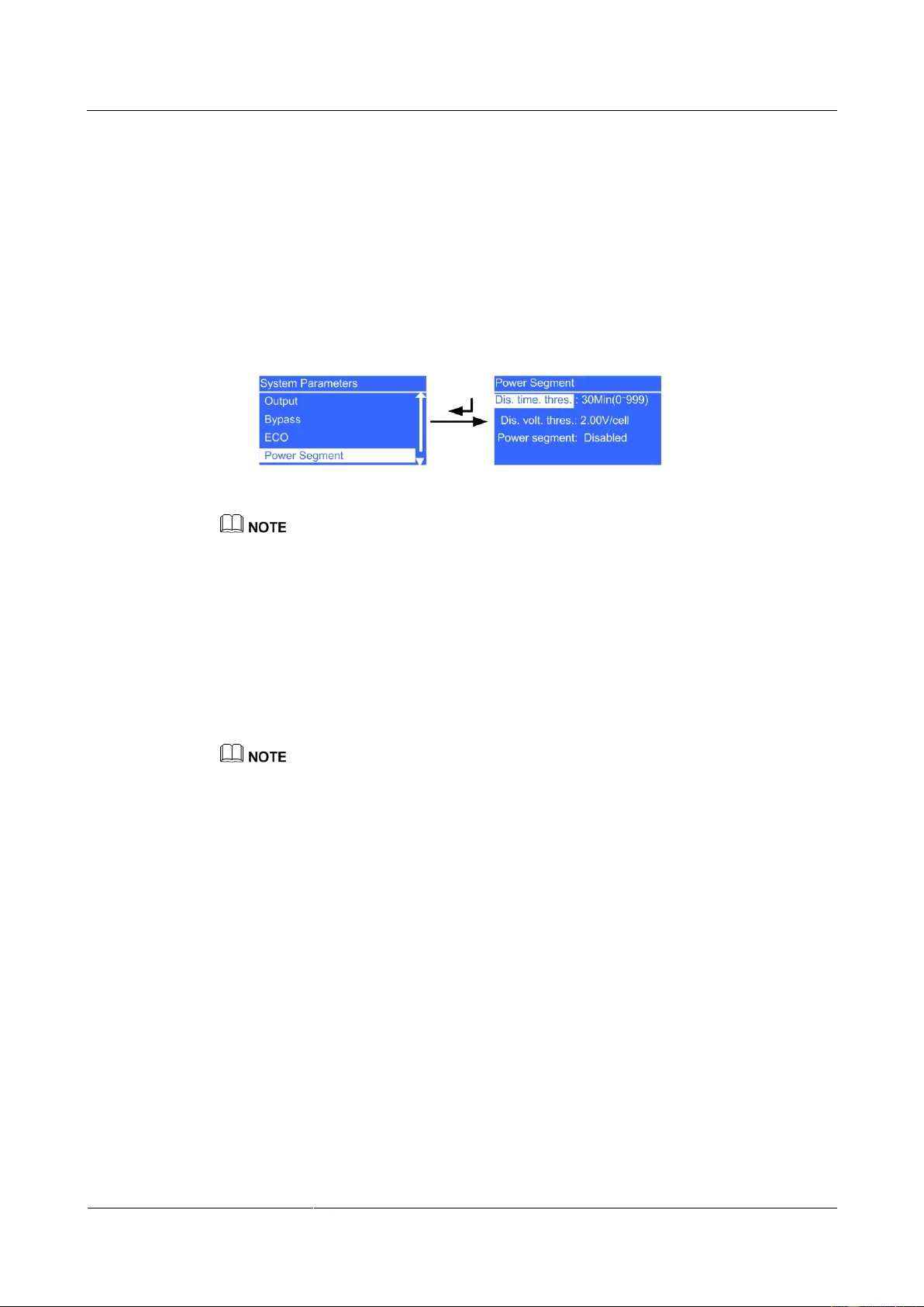
UPS2000-G-(6 kVA-20 kVA)
User Manual
Copyright © Huawei Technologies Co., Ltd.
The frequency range must be less than the current bypass frequency range. The
values include ±0.5 Hz, ±1 Hz, ±2 Hz (default), and ±3 Hz. The parameter is
configurable after the inverter shuts down.
− Single UPS ECO parameter
Determine whether to support ECO mode on a single UPS (ECO mode is not
supported in a parallel system). The values include Disabled and Enabled. The
default value is Disabled. The parameter is configurable after the inverter shuts
down.
Power Segment screen
Figure 4—34 Power Segment screen
In single UPS mode, primary loads connect to sL, and secondary loads connect to pL.
In single UPS mode, if power segment is enabled, pL is disconnected and sL continues with power
output when an overload occurs.
In a parallel system, UPS AC output power cables connect to pL.
− Dis. time. thres. parameter
pL terminal loading time in battery mode when power segment (not supported in a
parallel system) is enabled. In battery mode, if the discharge time exceeds this value,
the UPS disconnects from secondary loads. The value ranges from 0 Min to 999
Min, in units of minutes. The default value is 30 Min. The parameter is configurable
in non-battery mode or non-battery ECO mode.
The UPS2000-G-15 kVA/20 kVA supports battery ECO mode only in the case of two mains inputs. In
battery ECO mode, the bypass supplies power to the UPS, and batteries are used as backup power. If the
bypass is abnormal, the UPS transfers to battery mode.
− Dis. volt. thres. parameter
Set the lower threshold for the battery voltage when pL loading is allowed in battery
mode when power segment (not supported in a parallel system) is enabled. In
battery mode, if the battery voltage is less than this value, the UPS disconnects from
secondary loads. The value ranges from 1.90 V/cell to 2.25 V/cell. The default
value is 2.00 V/cell. The parameter is configurable in non-battery mode or
non-battery ECO mode
− Power segment parameter
Determine whether to enable power segment in singe UPS mode (power segment is
not supported in a parallel system). The values include Disabled and Enabled. The
default value is Disabled. The parameter is configurable after the inverter shuts
down.
Self-Load screen
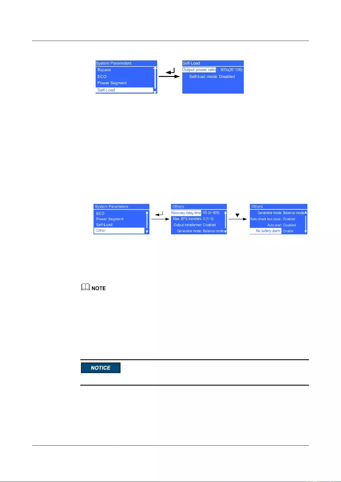
UPS2000-G-(6 kVA-20 kVA)
User Manual
Copyright © Huawei Technologies Co., Ltd.
Figure 4—35 Self-Load screen
− Output power ratio parameter
This parameter is used during the tests before shipment. The value ranges from 20%
to 100%. The default value is 80%. The parameter is configurable after the inverter
shuts down.
− Self-load mode parameter
This parameter is used during the tests before shipment. The values include
Disabled and Enabled. The default value is Disabled. The parameter is
configurable after the inverter shuts down.
Others screen
Figure 4—36 Others screen
− Recovery delay time parameter
Delay time that the UPS takes in transferring from battery mode to normal mode
when the mains recovers. The value ranges from 0S to 900S. The default value is
5S. The parameter is configurable after the inverter shuts down.
If Recovery delay time is set to 0S, the actual recovery delay time is 1 second.
− Max. BPS transfers parameter
Maximum number of bypass transfers within 30 minutes. The value ranges from 1
to 3. The default value is 3. When the number of bypass transfers exceeds the
maximum, the UPS keeps running is bypass mode (in ECO mode, the UPS keeps
running in normal mode). The parameter is configurable after the inverter shuts
down.
Do not set the UPS to ECO mode when the system output connects to an isolated transformer.
− Output transformer parameter
If an output transformer is connected, set the parameter to Enabled; otherwise, set
it to Disabled. The values include Disabled and Enabled. The default value is
Disabled. The parameter is configurable after the inverter shuts down.
UPS2000-G-(6 kVA-20 kVA)
User Manual
Copyright © Huawei Technologies Co., Ltd.
When you install a transformer on the output side, you must connect the load to the pL terminal and
disable power segment.
− Generator mode parameter
The values include Weak adaptability mode, Balance mode, and Strong
adaptability mode. The default value is Balance mode. When the mains input
voltage quality is good, select Weak adaptability mode; when the quality is
average (for example, the mains input is from a high-performance generator or a
common power grid), select Balance mode; when the quality is poor (for example,
the mains input is from a common generator), select Strong adaptability mode.
The parameter is configurable after the inverter shuts down.
− Auto check bus capa. parameter
Determine whether to automatically check the bus capacitance upon power-on and
generate capacitance failure warnings. The values include Disabled and Enabled.
The default value is Enabled. If the value is Enabled, UPS startup takes additional
30–180 seconds. The parameter is configurable after the inverter shuts down.
− Auto start parameter
Determine whether to automatically start inverter output after the UPS connects to
the mains. The values include Disabled and Enabled. The default value is Disabled.
The parameter is configurable after the inverter shuts down.
− No battery alarm
This parameter is set to Enabled by default. If it is set to Disabled, the No battery
alarm will not be reported. This parameter automatically changes to Enabled after
batteries are connected. It is configurable only when batteries are not connected.
If the batteries have been connected and you try to set this parameter, a message «Batteries have been
connected. This parameter cannot be set.» will be displayed.
Battery Parameters Screen
The configured number of batteries must match the actual number. When the actual number
changes, change the configured number. If the configured number is less than the actual
number, the battery lifespan is shortened. If the configured number is greater than the actual
number, battery leakage may cause a fire.
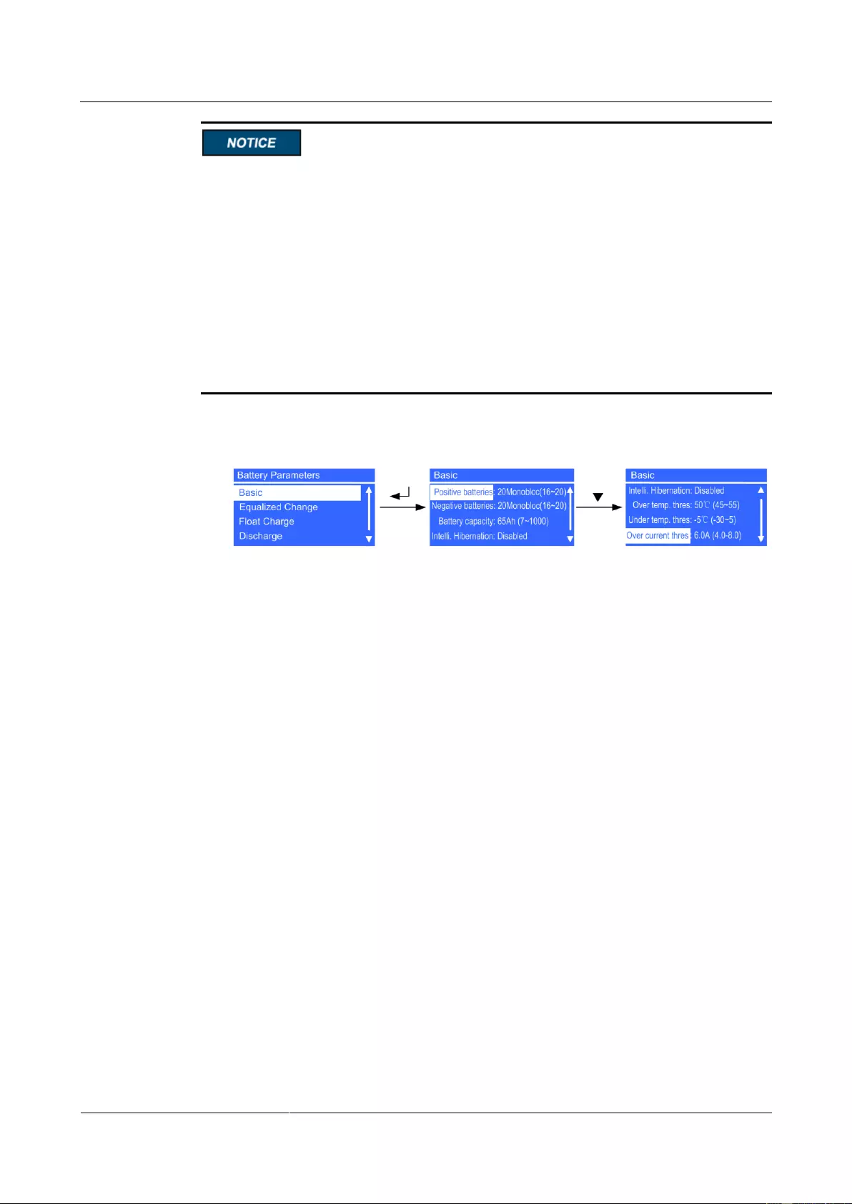
UPS2000-G-(6 kVA-20 kVA)
User Manual
Copyright © Huawei Technologies Co., Ltd.
The UPS2000-G-6 kVA/10 kVA parallel system cannot shares a battery string.
If a UPS2000-G-15 kVA/20 kVA parallel system shares a battery string, set the same
battery string capacity and charge current for each UPS.
Battery capacity (Ah) = Capacity of a single battery string x Number of parallel battery
strings/Number of parallel UPSs sharing a battery string. Maximum charge current (Ah) =
0.1 x Capacity of a single battery string x Number of parallel battery strings/Number of
parallel UPSs sharing a battery string. If the calculated maximum charge current is greater
than 4 A, set it 4 A. Use two UPSs sharing a 65 Ah battery string as an example: If the
calculated battery capacity is 65 x 1/2 = 32.5, set it to 32 Ah; if the calculated maximum
current is 0.1 x 65 x 1/2 = 3.25, set it to 3.0 A.
If a single 15 kVA/20 kVA UPS connects to two battery packs, the maximum charge
current must be less than or equal to 2.0 A.
Basic screen
Figure 4—37 Basic screen
− Number of batteries/Positive batteries and Negative batteries parameters
Set the number of batteries. The value ranges from 16 to 20. The default value is 20.
When the number of batteries N is less than 20, the system output power is derated
to N/20 in battery mode. The parameter is configurable in non-battery mode or
non-battery ECO mode. You need to set Number of batteries on the UPS2000-G-6
kVA/10 kVA, and set two battery strings (positive and negative) on the
UPS2000-G-15 kVA/20 kVA.
− Battery capacity parameter
Set the battery string capacity. The value ranges from 7 Ah to 1000 Ah. For the
UPS2000-G-6 kVA, the default value is 7 Ah on a standard model and 40 Ah on a
long backup time model; for the UPS2000-G-10 kVA, the default value is 9 Ah on a
standard model and 65 Ah on a long backup time model; for the UPS2000-G-15
kVA/20 kVA, the default value is 65 Ah on a long backup time model. Battery
capacity is the sum of all battery capacities, set the parameters based on the actual
battery capacity. The parameter is configurable in non-battery mode or non-battery
ECO mode.
− Intelli. Hibernation
This parameter is set to disabled by default. When it is set to enabled, the intelligent
battery hibernation function is enabled. The parameter is configurable in any mode.
− Overtemp. thres. parameter
Set an alarm threshold for high battery temperatures. The value ranges from 45ºC to
55ºC. The default value is 50ºC. The parameter is configurable in any mode.
− Undertemp. thres. parameter
Set an alarm threshold for low battery temperatures. The value ranges from –30ºC
to +5ºC. The default value is –5ºC. The parameter is configurable in any mode.
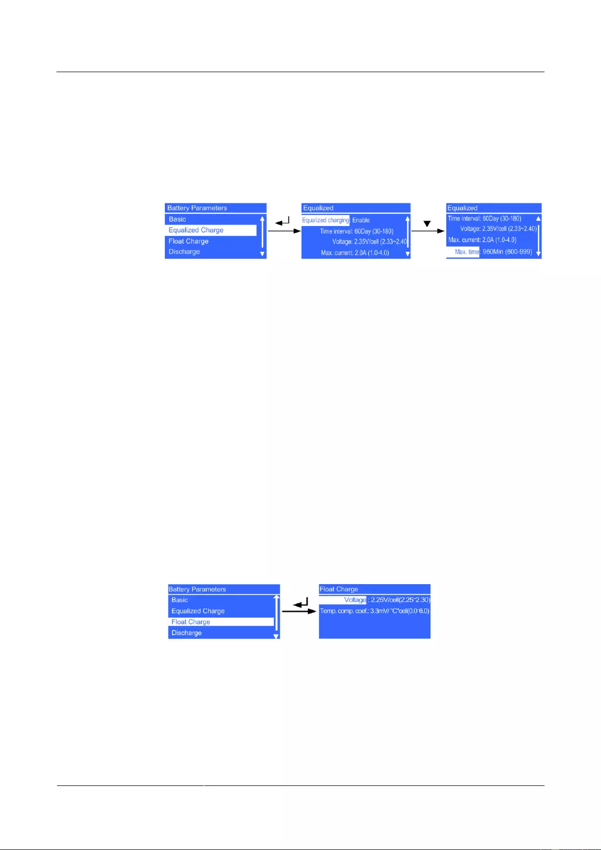
UPS2000-G-(6 kVA-20 kVA)
User Manual
Copyright © Huawei Technologies Co., Ltd.
− Overcurrent thres. parameter
Set an alarm threshold for battery overcurrent. On a standard model, the value
ranges from 2.0 A to 4.0 A, and the default value is 3.0 A. On a long backup time
model, the value ranges from 4.0 A to 8.0 A, and the default value is 6.0 A. The
parameter is configurable in any mode.
Equalized Charge screen
Figure 4—38 Equalized Charge screen
− Equalized charging parameter
Determine whether to enable equalized charging. The values include Disabled and
Enabled. The default value is Enabled. The parameter is configurable in any mode.
− Time interval parameter
Set the time interval for equalized charging. The value ranges from 30Day to
180Day. The default value is 60Day. The parameter is configurable in any mode.
− Voltage parameter
Set the battery equalized voltage. The value ranges from 2.33 V/cell to 2.40 V/cell.
The default value is 2.35 V/cell. The parameter is configurable in any mode.
− Max. current parameter
Set the maximum equalized current. On a standard model, the value ranges from 1.0
A to 2.0 A, and the default value is 2.0 A. On a long backup time model, the value
ranges from 1.0 A to 4.0 A, and the default value is 2.0 A. The parameter is
configurable in any mode.
− Max. time parameter
Set the maximum equalized charge time. The value ranges from 600Min to 999Min.
The default value is 960Min. The parameter is configurable in any mode.
Float Charge screen
Figure 4—39 Float Charge screen
− Voltage parameter
Set the battery float voltage. The value ranges from 2.25 V/cell to 2.30 V/cell. The
default value is 2.25 V/cell. The parameter is configurable in any mode.
− Temp. comp. coef. parameter
Set a float voltage correction coefficient based on the battery temperature when a
battery temperature sensor is connected. The value ranges from 0.0 mV/°C*cell to
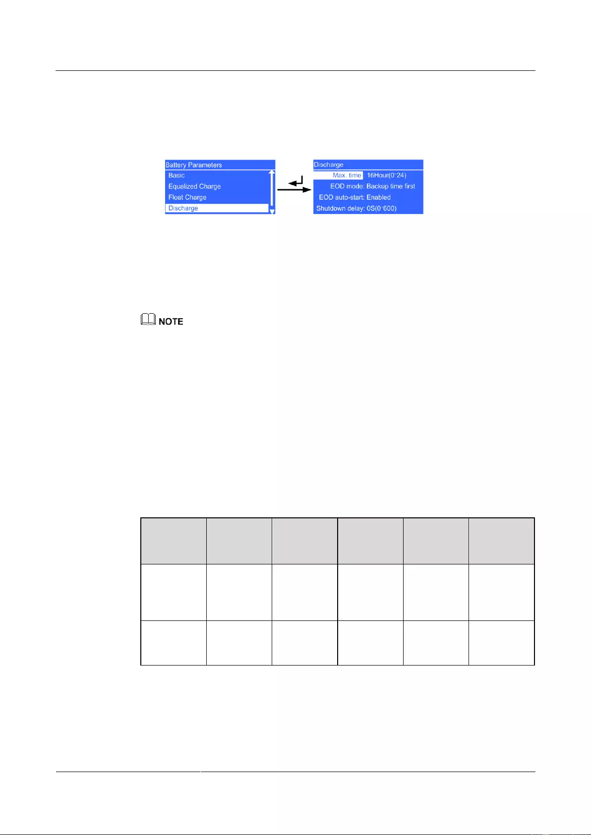
UPS2000-G-(6 kVA-20 kVA)
User Manual
Copyright © Huawei Technologies Co., Ltd.
6.0 mV/°C*cell. The default value is 3.3 mV/°C*cell. The parameter is configurable
in any mode.
Discharge screen
Figure 4—40 Discharge screen
− Max. time parameter
Set the maximum discharge time. When the discharge time reaches the value, the
UPS powers off. The value ranges from 0Hour to 24Hour. The default value is
16Hour. If you set the value to 0Hour, the discharge time is not limited. The
parameter is configurable in non-battery mode or non-battery ECO mode.
If you expect the battery discharge time to be greater than 24 hours, set Max. time to 0 hour.
Otherwise, the system may power off.
If you set Max. time to 0 hour, the battery string may remain in the small-current discharge state
according to the proportion of the battery capacity to the load power, which affects the battery
lifecycle.
− EOD mode parameter
Determine the power backup time. The values include Backup time first (ensures
system running and has a long backup time, Table 4-5 shows the EOD setting
values), Batt. protect first (protects batteries and extends the battery lifespan,
Table 4-6 shows the EOD setting values), and Balanced mode (Table 4-7 shows the
EOD setting values). The default value is Backup time first. The parameter is
configurable in non-battery mode or non-battery ECO mode. EOD is short for end
of discharge.
Table 4-5 Backup time first EOD setting values
Low voltage
warning
threshold
(V/cell)
UPS2000-G-(6 kVA-20 kVA)
User Manual
Copyright © Huawei Technologies Co., Ltd.
Table 4-6 Batt. protect first EOD setting values
Low voltage
warning
threshold
(V/cell)
Table 4-7 Balanced mode EOD setting values
Low voltage
warning
threshold
(V/cell)
− EOD auto-start parameter
Determine whether to automatically start inverter output after the mains becomes
normal. The values include Disabled and Enabled. The default value is Enabled.
The parameter is configurable after the inverter shuts down.
− Shutdown delay parameter
When the delay time reaches the value after UPS transfers to battery mode, the UPS
powers off. The value ranges from 0S to 600S. The default value is 0S. The value
interval is 30S. For example, the value can be 0S, 30S, 60S, and 90S. If the delay
time is set to 0S, the shutdown delay function is disabled. If the delay time is set to
other values, ensure that backup time is greater than shutdown delay time.
Otherwise, the power supply to loads may be disconnected. The parameter is
configurable in non-battery mode or non-battery ECO mode.
Shutdown delay parameters are asynchronous in a parallel system. When used in a parallel system, set
the same shutdown delay parameter for different UPSs.
Shallow Discharge screen

UPS2000-G-(6 kVA-20 kVA)
User Manual
Copyright © Huawei Technologies Co., Ltd.
Figure 4—41 Shallow Discharge screen
− Test notification parameter
Determine whether to periodically send shallow discharge test notifications. The
values include Disabled and Enabled. The default value is Disabled. If the value is
Enabled, the system sends shallow discharge test notifications. The parameter is
configurable in any mode.
− Time interval parameter
Set the time interval for shallow discharge tests. The value ranges from 30Day to
90Day. The default value is 60Day. The parameter is configurable in any mode.
− Discharge ratio parameter
Set the proportion of the discharge capacity to the total discharge capacity. The
value ranges from 10% to 50%. The default value is 20%. The parameter is
configurable in any mode.
Restoring Factory Settings
You can restore factory settings after the inverter shuts down.
4.6.4 Control Screen
On the Main Menu screen, select Control, and press . The Control screen is displayed.
Startup Menu
The Startup menu allows you to restart the inverter.
Figure 4—42 Startup screen
Shutdown Menu
The Shutdown menu allows you to shut down the inverter.
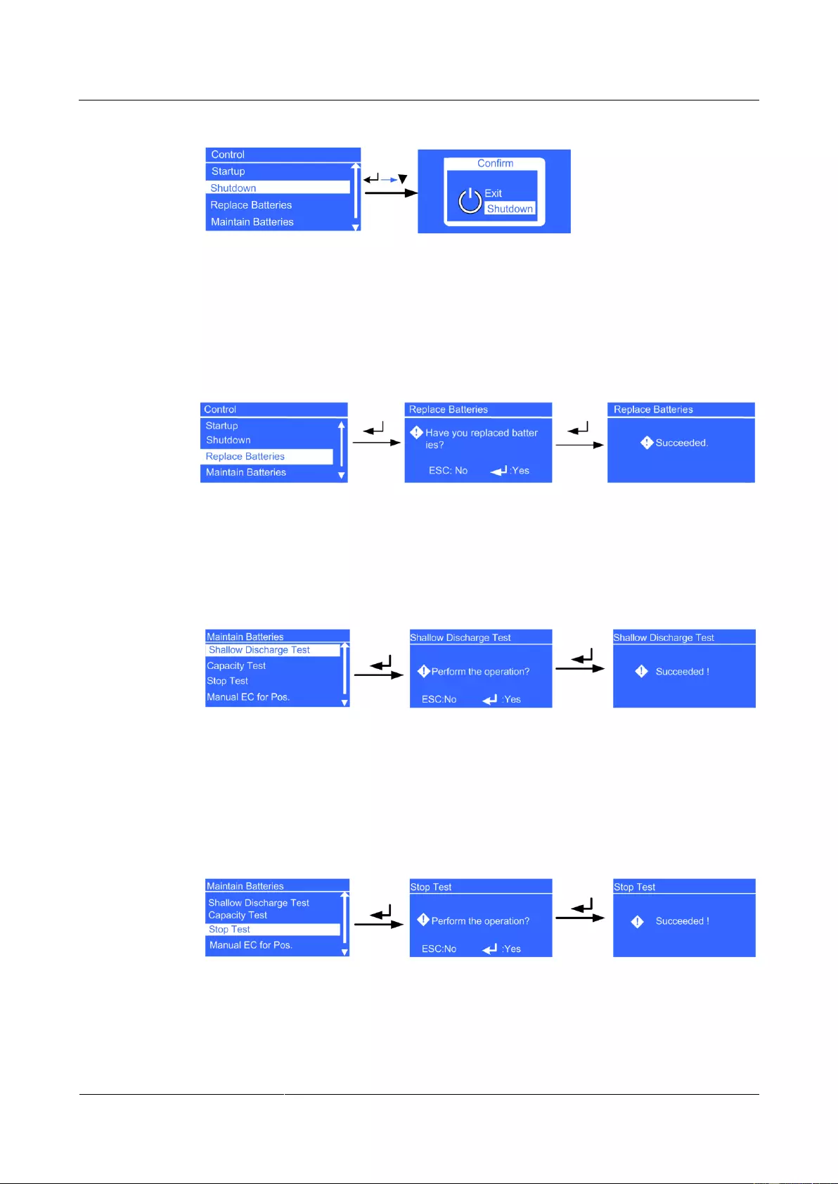
UPS2000-G-(6 kVA-20 kVA)
User Manual
Copyright © Huawei Technologies Co., Ltd.
Figure 4—43 Shutdown screen
Replace Batteries Menu
If the batteries have been replaced for the system, set this parameter. The parameter is
configurable in non-battery mode or non-battery ECO mode.
Figure 4—44 Replace Batteries screen
Maintain Batteries Menu
Shallow Discharge Test menu
Figure 4—45 Shallow Discharge Test screen
Capacity Test menu
After you completely discharge batteries, the load ratio must be in the range of
20%–80%.
Stop Test menu
Figure 4—46 Stop Test screen
Stop the shallow discharge test or capacity test.
Manual EC for Pos. menu
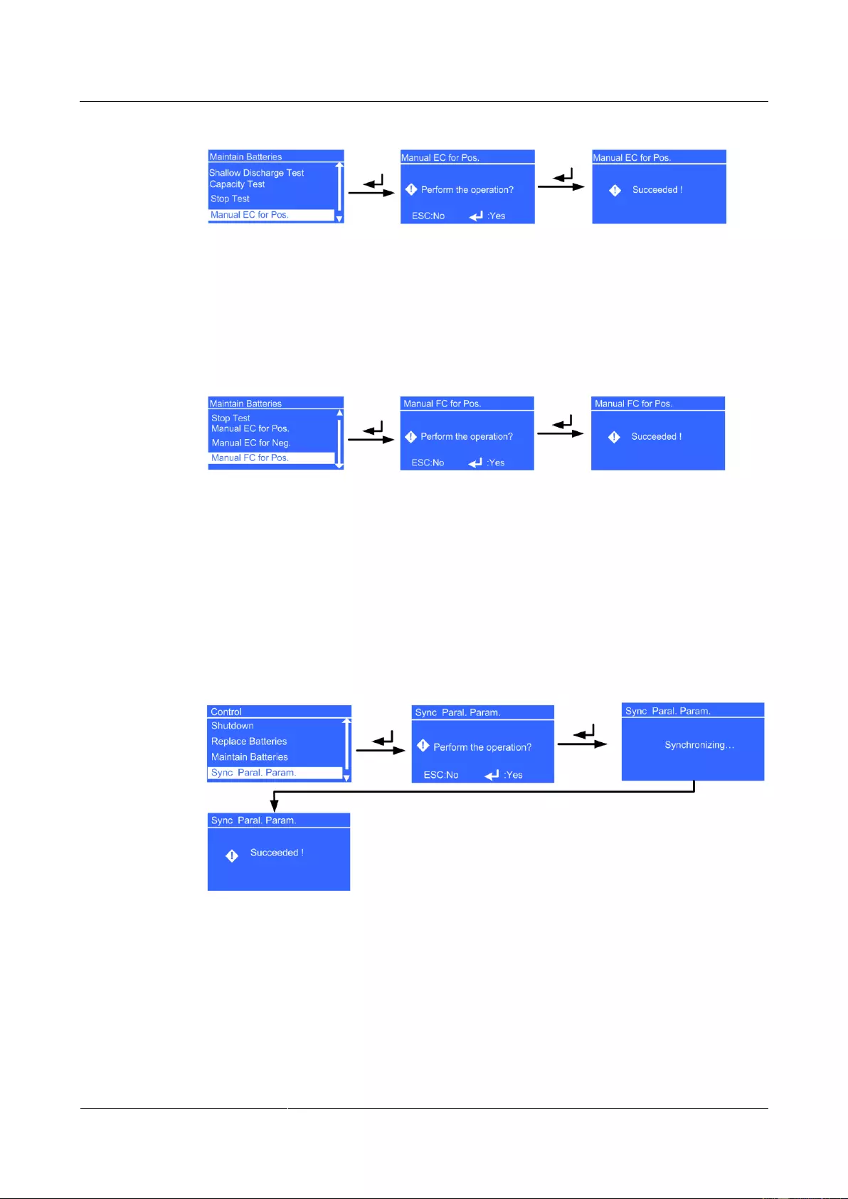
UPS2000-G-(6 kVA-20 kVA)
User Manual
Copyright © Huawei Technologies Co., Ltd.
Figure 4—47 Manual EC for Pos. screen
Perform equalized charging on batteries forcibly. For the 6 kVA and 10 kVA UPSs, perform
manual equalized charging. For the 15 kVA and 20 kVA UPSs, batteries in positive and
negative groups are manually switched to equalized charging respectively.
Manual FC for Pos. menu
Figure 4—48 Manual FC for Pos. screen
Perform float charging on batteries forcibly. For the 6 kVA and 10 kVA UPSs, perform manual
float charging. For the 15 kVA and 20 kVA UPSs, batteries in positive and negative groups are
manually switched to float charging respectively.
Sync Paral. Param. Menu
The menu allows you to synchronize the parameters from one UPS to the other UPSs in the
parallel system. The UPS running in inverter output state cannot be synchronized.
Figure 4—49 Sync Paral. Param. screen
Resetting the Password
Enter a feature code to restore the preset password.
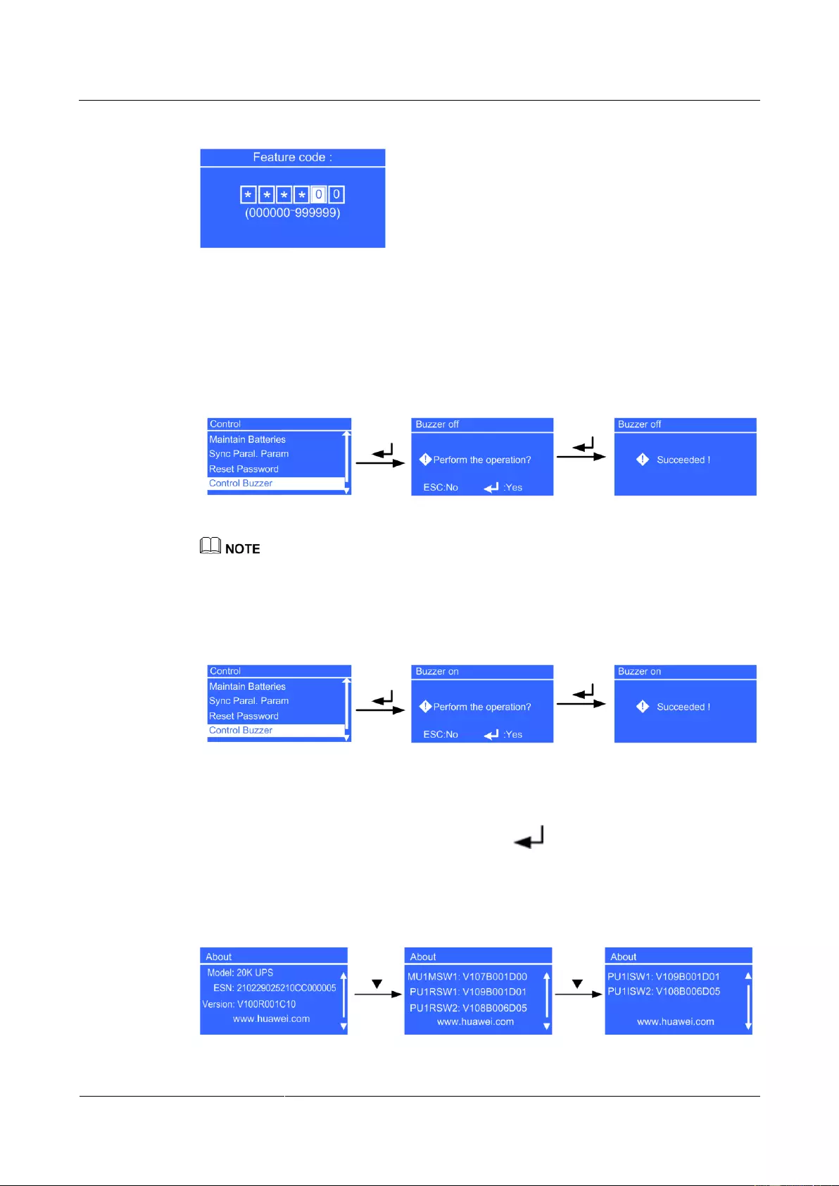
UPS2000-G-(6 kVA-20 kVA)
User Manual
Copyright © Huawei Technologies Co., Ltd.
Figure 4—50 Resetting the password
Control Buzzer
Control Buzzer control the buzzer on/off. If the buzzer on, click Control Buzzer transfer to
Buzzer off.
Figure 4—51 Buzzer off screen
If Control Buzzer is used for muting the alarm tone, the alarm tone should be unmuted by using Control
Buzzer or power on the UPS again. Otherwise, when a new alarm is generated, it cannot buzz again.
If the buzzer off, click Control Buzzer transfer to Buzzer on.
Figure 4—52 Buzzer on screen
4.6.5 About Screen
On the Main Menu screen, select About, and press . The About screen is displayed, as
shown in Figure 4-53.
You can view the UPS model, equipment serial number (ESN), and version number.
Figure 4—53 About screen

UPS2000-G-(6 kVA-20 kVA)
User Manual
Copyright © Huawei Technologies Co., Ltd.
MU1MSW1, PU1RSW1, PU1RSW2, PU1ISW1, and PU1ISW2 is the version for the component. When
the component does not exist, NA is displayed for Version. PU1ISW1 and PU1ISW2 are not available
for the UPS 6 kVA and UPS 10 kVA.
Model parameter
The UPS model is 20K UPS.
ESN parameter
This item provides the UPS ESN.
Version parameter
This item provides the UPS version.
MU1MSW1 parameter
This item provides the main monitoring software version.
PU1RSW1 parameter
This item provides rectifier power software version.
PU1RSW2 parameter
This item provides the rectifier logic software version.
PU1ISW1 parameter
This item provides the inverter power software version.
PU1ISW2 parameter
This item provides the inverter logic software version.

UPS2000-G-(6 kVA-20 kVA)
User Manual
Copyright © Huawei Technologies Co., Ltd.
5 Operations
5.1 Checking Before Powering On the UPS
AC power cable colors comply with local electrical regulations.
No short circuits occur in inputs and outputs.
Cables are securely connected.
Battery cables are correctly connected to battery terminals. The battery voltage meets the
requirements.
Cables are properly connected between the UPS and batteries.
Input circuit breakers and load circuit breakers are OFF.
Power cables and signal cables are correctly identified.
The input phase sequence is correct.
Cables are neatly routed and securely bound.
Devices are installed and cables are routed in ways that facilitate modification, capacity
expansion, and maintenance.
Parallel cables are properly connected.
The UPS is properly grounded.
The voltage between the neutral wire and the ground cable is less than 5 V AC.
The input voltage rang for the mains to start the UPS is 120–280 V AC (or 80–280 V AC
after the UPS powers on). The battery voltage range is (Number of batteries x 10.  –280
–280
V DC.
5.2 Single UPS Operations
5.2.1 Starting the UPS
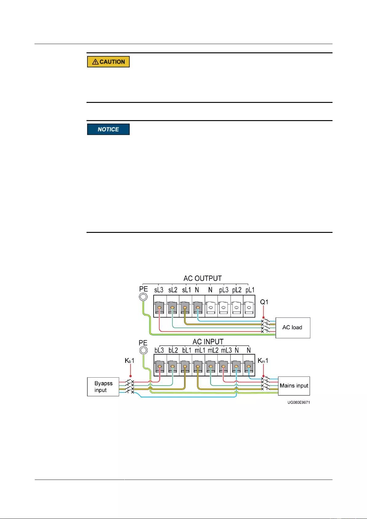
UPS2000-G-(6 kVA-20 kVA)
User Manual
Copyright © Huawei Technologies Co., Ltd.
The configured number of batteries must match the actual number. When the actual number
changes, change the configured number. If the configured number is less than the actual
number, the battery lifespan is shortened. If the configured number is greater than the actual
number, battery leakage may cause a fire.
If the system uses three-phase input three-phase output, set Output mode to Three-phase.
If the system uses three-phase input single-phase output or single-phase input single-phase
output, set Output mode to Single-phase.
Set Voltage level and Frequency level based on the rated voltage and frequency. In the
case of single-phase output, set Voltage level to 220 V (default), 230 V, or 240 V; in the
case of three-phase output, set Voltage level to 380 V (default), 400 V, or 415 V.
Battery parameters are configurable in non-battery mode or non-battery ECO mode.
Set Positive batteries and Negative batteries. The value ranges from 16 to 20. The
default value is 20.
Set Battery capacity to the total capacity of all batteries actually connected. The value
ranges from 7 Ah to 1000 Ah. The default value is 65 Ah.
This section describes how to start the UPS2000-G-15 kVA/20 kVA.
Figure 5-1 Connecting cables to the UPS2000-G-15 kVA/20 kVA (three-phase input three-phase
output, dual mains)
Starting the UPS in Normal Mode
Step 1 Close the external battery circuit breaker (if there is), or connect battery cables.
Step 2 Close the UPS mains input circuit breaker Km1 and bypass input circuit breaker Kb1.
UPS2000-G-(6 kVA-20 kVA)
User Manual
Copyright © Huawei Technologies Co., Ltd.
The initialization screen is displayed.
Perform Step 2 when there are two mains inputs. In the case of one mains input, you need only to close
the UPS mains input circuit breaker.
Step 3 The UPS enters bypass mode. The UPS sL delivers bypass voltages, and pL delivers no
voltage. When the initialization is complete, perform the following operations:
Initial startup
On the Settings wizard screen, set the language (the preset language is English), system
parameters, and battery parameters. Press . The standby screen is displayed.
Non-initial startup
When the initialization is complete, the standby screen is displayed. On the standby
screen, press to enter the main menu. Choose Main Menu > Settings > System
Parameters > Output to view output settings: if the system uses three-phase input
three-phase output, Output mode is set to Three-phase; if the system uses three-phase
input single-phase output or single-phase input single-phase output, Output mode is set
to Single-phase. Voltage level and Frequency level are set based on the rated voltage
and frequency. Press ESC to return to the standby screen.
Step 4 Start the UPS in normal mode by using one of the following methods:
On the standby screen, hold down more than 5 seconds. Release the button when
you hear a beep sound. The startup screen is displayed. If the UPS starts successfully, it
enters normal mode.
On the standby screen, hold down to enter the main menu. Select Startup in the
Control menu, and press . The Starting message is displayed. If the UPS starts
successfully, it enters normal mode.
The two methods in Step 4 are called «startup operations» in this section.
Step 5 When the UPS runs properly, close the UPS AC output circuit breaker Q1, and start the loads.
To prevent triggering overload protection, start the loads with higher power and then loads with lower
power.
—-End
Starting the UPS in Battery Mode
Step 1 Close the external battery circuit breaker (if there is), or connect battery cables.
Step 2 Press on the control panel.
The LCD starts. The initialization screen is displayed.
Initial startup
When the initialization is complete, the Settings wizard screen is displayed. Set the
language (the preset language is English), system parameters, and battery parameters,
and press . The standby screen is displayed.

UPS2000-G-(6 kVA-20 kVA)
User Manual
Copyright © Huawei Technologies Co., Ltd.
Non-initial startup
When the initialization is complete, the standby screen is displayed. On the standby
screen, press to enter the main menu. Choose Main Menu > Settings > System
Parameters > Output to view output settings: if the system uses three-phase input
three-phase output, Output mode is set to Three-phase; if the system uses three-phase
input single-phase output or single-phase input single-phase output, Output mode is set
to Single-phase. Voltage level and Frequency level are set based on the rated voltage
and frequency. Press ESC to return to the standby screen.
Step 3 Perform «startup operations» on the UPS. The UPS runs in battery mode.
Step 4 When the UPS runs properly, close the UPS AC output circuit breaker Q1, and start the loads.
To prevent triggering overload protection, start the loads with higher power and then loads with lower
power.
—-End
5.2.2 Shutting down the UPS
Shutting down the Inverter
To shut down the inverter, perform any of the following operations:
On the default screen, hold down ESC for more than 5 seconds. Release the button when
you hear a beep sound. The inverter shuts down, and the UPS transfers to bypass mode.
On the default screen, press to enter the main menu. Choose Shutdown to shut
down the inverter. The UPS transfers to bypass mode.
The two methods are called «shutdown operations» in this section.
Shutting down the UPS
Step 1 Shut down the loads.
Step 2 Perform «shutdown operations» on the UPS. The inverter shuts down. The UPS transfers to
bypass mode.
Step 3 Open the UPS mains input circuit breaker Km1, bypass input circuit breaker Kb1, and output
circuit breaker Q1.
Perform Step 3 when there are two mains inputs. In the case of one mains input, you need only to open
the UPS mains input circuit breaker.
Step 4 Open the external battery circuit breaker (if there is), or disconnect battery cables.
—-End
5.2.3 Performing EPO
Turn on the EPO switch (provided by the customer). The UPS enters the EPO state. That is,
the inverter shuts down, and the UPS will not transfer to bypass mode.
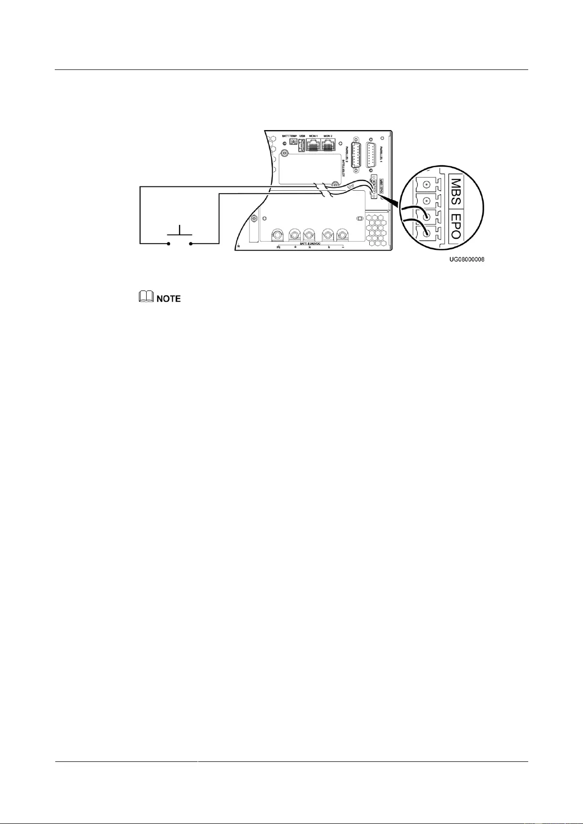
UPS2000-G-(6 kVA-20 kVA)
User Manual
Copyright © Huawei Technologies Co., Ltd.
Figure 5-2 shows the EPO cable connection on a single UPS.
Figure 5-2 EPO cable connection on a single UPS
Connect an external switch to the EPO port on the UPS. After you turn on the switch, the inverter
shuts down, and the UPS will not transfer to bypass mode. Output terminals completely power off,
which meets the EPO purpose.
The external EPO switch (switch or dry contact signals controlled by a switch) is provided by the
customer.
5.3 Parallel System Operations
This section describes operations on a UPS2000-G-15 kVA/20 kVA parallel system.
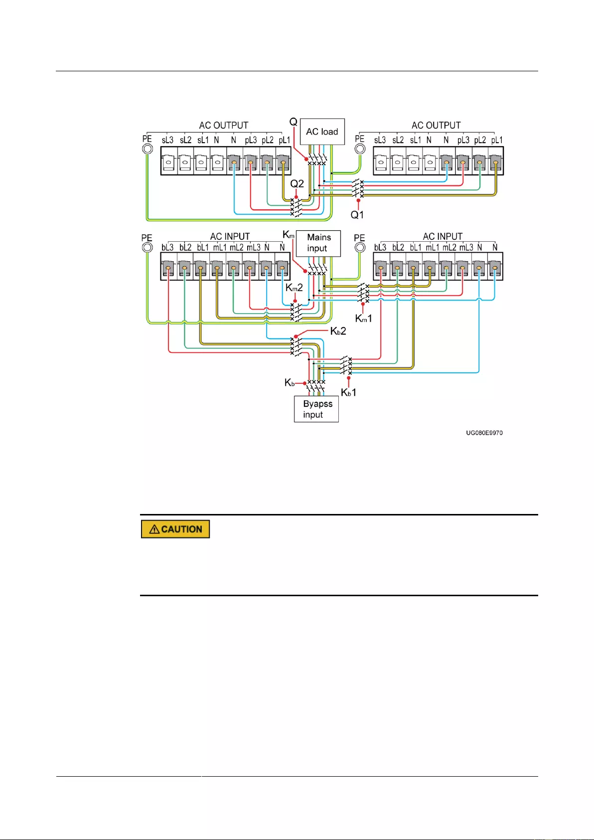
UPS2000-G-(6 kVA-20 kVA)
User Manual
Copyright © Huawei Technologies Co., Ltd.
Figure 5-3 Connecting cables to the UPS2000-G-15 kVA/20 kVA parallel system (three-phase
input three-phase output, dual mains) equipped with no PDU
5.3.1 Starting the Parallel System
The configured number of batteries must match the actual number. When the actual number
changes, change the configured number. If the configured number is less than the actual
number, the battery lifespan is shortened. If the configured number is greater than the actual
number, battery leakage may cause a fire.

UPS2000-G-(6 kVA-20 kVA)
User Manual
Copyright © Huawei Technologies Co., Ltd.
If a parallel system shares a battery string, set the same battery string capacity and charge
current for each UPS.
Before you start the parallel system, ensure that UPS output circuit breakers are both ON.
Check that parallel parameters have been synchronized.
In a 4+0 parallel system, the four parallel cables must be of the same length (1 meter or
longer), and connect to a remote junction box.
In the parallel system that uses the TN-C power distribution system, install four magnetic
rings on the PE cable on each UPS, bind the four magnetic rings together using binding
tape, and secure them in the nearest place.
Before starting a parallel system, ensure that all circuit breakers on the output side are OFF,
and do not start loads.
To prevent triggering overload protection, start the loads with higher power and then loads
with lower power.
Starting the Parallel System in Normal Mode
Perform the following steps to start the parallel system for the system to work in normal
mode.
Step 1 Close the external battery circuit breakers (if there are), or connect battery cables.
Step 2 Close the following circuit breakers in sequence: UPS mains input circuit breakers Km1 and
Km2, general mains input circuit breaker Km, bypass input circuit breakers Kb1 and Kb2,
general bypass input circuit breaker Kb, and UPS AC output circuit breakers Q1 and Q2.
The initialization screen is displayed. The parallel system supplies no power.
Perform Step 2 when there are two mains inputs. In the case of one mains input, you need only to
close the UPS mains input circuit breakers and general mains input circuit breaker.
If a PDU is configured, close the following circuit breakers: general mains input circuit breaker,
general bypass input circuit breaker, mains input circuit breakers for all UPSs on the PDU, bypass
input circuit breakers, and output circuit breakers for all UPSs on the PDU. The initiation screen is
displayed.
Step 3 Perform the following operations on each UPS:
Initial startup
a. Setting parameters on the Settings wizard screen
When the initialization is complete, the Settings wizard screen is displayed. Set the
language, system parameters, and battery parameters, and press . The standby
screen is displayed.
b. Settings for transferring from single mode (preset) to parallel mode
On the standby screen, press . Choose Main Menu > Settings > System
Parameters > Parallel > Single/Parallel to transfer from single mode to parallel
mode. Press ESC to return to the standby screen.
Non-initial startup
When the initialization is complete, the standby screen is displayed. On the standby
screen, press to enter the main menu. Choose Main Menu > Settings > System

UPS2000-G-(6 kVA-20 kVA)
User Manual
Copyright © Huawei Technologies Co., Ltd.
Parameters > Output to view output settings: if the system uses three-phase input
three-phase output, Output mode is set to Three-phase; if the system uses three-phase
input single-phase output or single-phase input single-phase output, Output mode is set
to Single-phase. Voltage level and Frequency level are set based on the rated voltage
and frequency. Press ESC to return to the standby screen.
Step 4 Perform «startup operations» on each UPS in the parallel system.
The parallel system transfers to normal mode.
After you perform «startup operations» on UPS 1 to UPS n one by one, UPS 1 to UPS n are starting. If
you do not perform «startup operations» on the other UPSs in 5 minutes, UPS 1 to UPS n enter normal
mode, and the other UPSs supply no power.
Step 5 When the parallel system runs properly, close the general output circuit breaker Q (provided
by the customer) and then branch output circuit breakers (provided by the customer), and start
the loads.
—-End
Starting the Parallel System in Battery Mode
Step 1 Close the external battery circuit breakers (if there are), or connect battery cables.
Step 2 Close the AC output circuit breakers Q1 and Q2 for the parallel system.
Step 3 Press on each control panel.
The initialization screen is displayed on each LCD. On the standby screen, press to
enter the main menu. Choose Main Menu > Settings > System Parameters > Output to
view output settings: if the system uses three-phase input three-phase output, Output mode is
set to Three-phase; if the system uses three-phase input single-phase output or single-phase
input single-phase output, Output mode is set to Single-phase. Voltage level and Frequency
level are set based on the rated voltage and frequency. Press ESC to return to the standby
screen.
Step 4 Perform the following operations on each UPS:
Initial startup
a. Setting parameters on the Settings wizard screen
When the initialization is complete, the Settings wizard screen is displayed. Set the
language, system parameters, and battery parameters, and press the standby
screen is displayed.
b. Settings for transferring from single mode (preset) to parallel mode
On the standby screen, press . Choose Main Menu > Settings > System
Parameters > Parallel > Single/Parallel to transfer from single mode to parallel
mode. Press ESC to return to the standby screen.
Non-initial startup
When the initialization is complete, the standby screen is displayed.
Step 5 Perform «startup operations» on each UPS.
The parallel system transfers to battery mode.

UPS2000-G-(6 kVA-20 kVA)
User Manual
Copyright © Huawei Technologies Co., Ltd.
After you perform «startup operations» on UPS 1 to UPS n one by one, UPS 1 to UPS n are starting. If
you do not perform «startup operations» on the other UPSs in 5 minutes, UPS 1 to UPS n enter normal
mode, and the other UPSs supply no power.
Step 6 When the parallel system runs properly, close the general output circuit breaker Q (provided
by the customer) and then branch output circuit breakers (provided by the customer), and start
the loads.
—-End
5.3.2 Shutting down the Parallel System
Shutting down a Single UPS in the Parallel System
Step 1 Perform «shutdown operations» twice on a single UPS within 30 seconds (for example, UPS 1
shown in Figure 5-3) in the parallel system. The UPS is shutting down. The other UPSs
continue working.
The UPSs in the parallel system have shut down supply no power (the mains indicator, bypass indicator,
and battery indicator are Off).
Step 2 Open the UPS mains input circuit breaker Km1, bypass input circuit breaker Kb1, and the AC
output circuit breaker Q1. After all indicators turn off and fans stop, the UPS shuts down.
Step 3 Open the external battery circuit breaker (if there is), or disconnect battery cables. The UPS
exits the parallel system.
To merely shut down the UPS, perform Step 1 only.
—-End
Transferring the Parallel System to Bypass Mode
Perform «shutdown operations» on each UPS in the parallel system. All inverters shut down at
the same time, and the parallel system transfers to bypass mode.
Shutting down the Parallel System
Step 1 Shut down the loads.
Step 2 Perform «shutdown operations» on each UPS in the parallel system. All inverters shut down at
the same time. The parallel system transfers to bypass mode.
Step 3 Open the following circuit breakers in sequence for each UPS: UPS mains input circuit
breakers Km1 and Km2, general mains input circuit breaker Km, bypass input circuit breakers
Kb1 and Kb2, general bypass input circuit breaker Kb, UPS AC output circuit breakers Q1 and
Q2, and general AC output circuit breaker Q. After all indicators turn off and fans stop, the
UPSs shut down, and the loads power off.
Perform Step 3 when there are two mains inputs. In the case of one mains input, you need only to open
the following circuit breakers in sequence for each UPS: UPS mains input circuit breakers, general
mains input circuit breaker, UPS AC output circuit breakers, and general AC output circuit breaker.
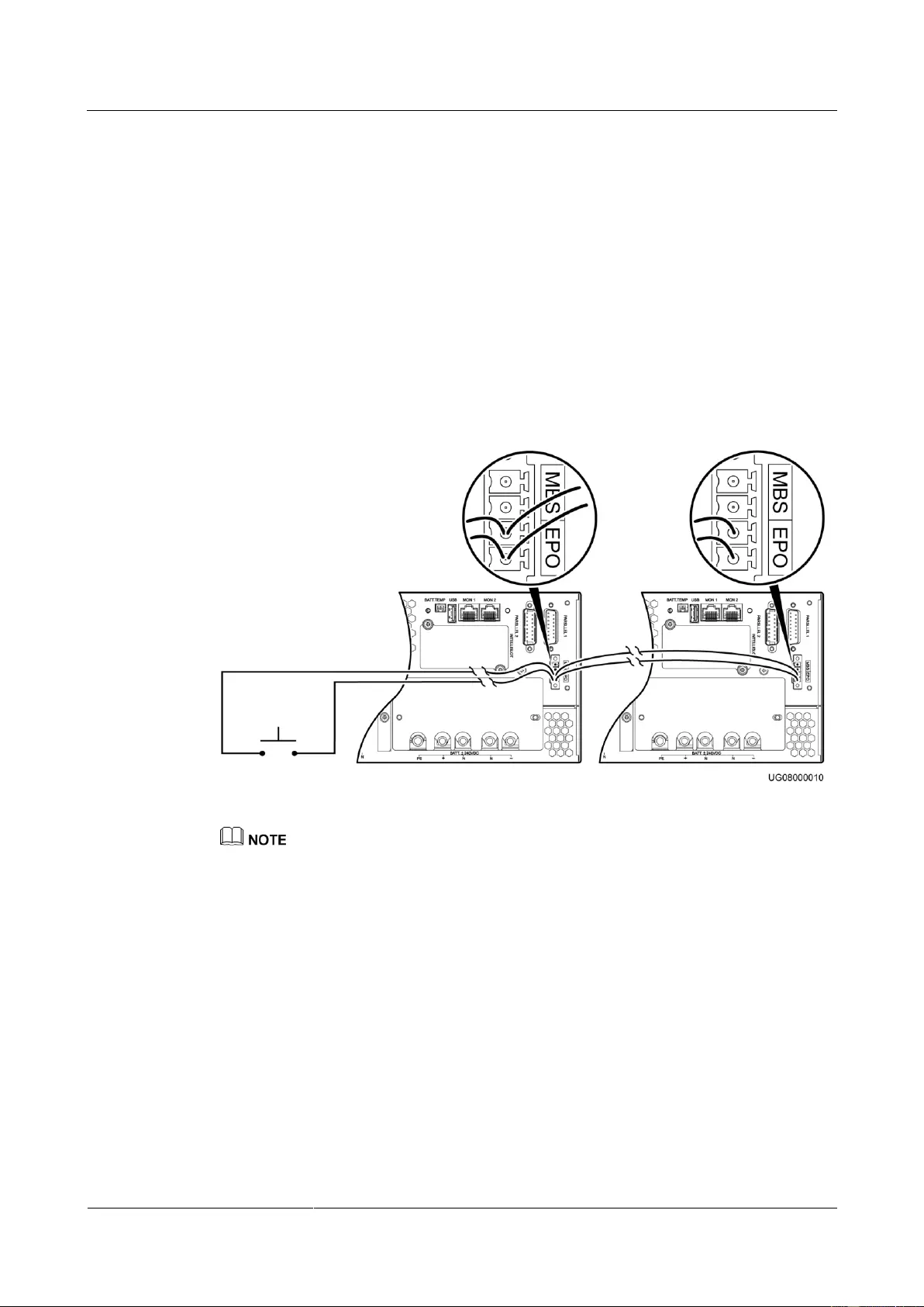
UPS2000-G-(6 kVA-20 kVA)
User Manual
Copyright © Huawei Technologies Co., Ltd.
Step 4 Open the external battery circuit breaker for each UPS or the general battery circuit breaker
(when all UPSs share a battery string). If no external battery circuit breaker is configured,
disconnect battery cables from each UPS.
—-End
5.3.3 Performing EPO
Turn on the EPO switches (provided by the customer). The parallel system enters the EPO
state. That is, the inverters shut down, and the parallel system will not transfer to bypass
mode.
Figure 5-4 shows the EPO cable connection in a parallel system.
Figure 5-4 EPO cable connection in a parallel system
Connect an external switch to the EPO port on the UPS. After you turn on the switch, the UPS stops
inverter output and does not transfer to bypass mode. Output terminals completely power off, which
meets the emergency power-off purpose.
The external EPO switch (switch or dry contact signals controlled by a switch) is provided by the
customer.

UPS2000-G-(6 kVA-20 kVA)
User Manual
Copyright © Huawei Technologies Co., Ltd.
6 Communications
6.1 Optional Communications Components
The optional communications components include the SNMP card, Modbus card, and dry
contact card.
6.2 SNMP Card
The SNMP card is an optional monitoring component of the UPS. It provides Simple Network
Management Protocol (SNMP) agent and web management functions. The SNMP card allows
users to remotely manage the UPS by using a network management system (NMS), NetEco,
or a web browser on a computer network. A maximum of 16 SNMPv3 users and 1
SNMPv1&SNMPv2c user can manage the UPS. A maximum of 2 web users can manage the
UPS online.
The SNMP card has an exquisite, advanced, and unique design, and features high
performance and reliability. It has the following functions and features:
Supports UPS2000-G series and implements parallel system management using only one
SNMP card.
Adapts to the 10 Mbit/s, 100 Mbit/s fast Ethernet (FE) by using an IP address that is
configurable on the LCD.
Supports SNMP, Hypertext Transfer Protocol Secure (HTTPS), and Secure Shell (SSH).
Supports SNMP agent v1, v2c, and v3. The UPS MIB library can be downloaded from
its own web page, instead of any CD-ROM.
Enables remote management on Windows or Linux using a web browser. The supported
web browsers include Internet Explorer 8, Internet Explorer 9, Internet Explorer 10,
Internet Explorer 11, and Firefox 33.1.
Provides an access security mechanism, assigns rights to users based on roles, and
implements IP address control over HTTPS, SNMPv3, and SNMP access to prevent
unauthorized access.
Provides comprehensive UPS management, such as producing a current diagram,
displaying alarms, controlling UPS running, collecting performance data statistics, as
well as allowing users to view, retrieve, and export historical alarms and operation logs.
Supports optional components such as temperature and humidity modules, AI/DI Module,
iBAT 2.0, and external dry contact card.

UPS2000-G-(6 kVA-20 kVA)
User Manual
Copyright © Huawei Technologies Co., Ltd.
Works with NetShutdown, a computer and server security shutdown program developed
by Huawei, to automatically shut down the computers and servers where NetShutdown is
installed to protect customer data and reduce loss.
Works with RCCMD, a client shutdown software developed by Generex, to
automatically and safely shut down the client that is installed with the RCCMD, thereby
protecting customers’ data and preventing loss.
Alarm information is sent to the specified user mailbox at the specified time.
6.3 Modbus Card
The RMS-MODBUS01A provides an RS485 networking solution to remotely manage the
UPS.
The card implements the following functions by setting the DIP switches:
Selects the Modbus protocol by using a DIP switch over the RS485 communications
protocol.
Uses a DIP switch to select a two-wire or four-wire system.
Provides a DIP switch to select a build-out resistor.
Provides a DIP switch for setting the optional card address.
Supports hot swap.
6.4 Dry Contact Card
The RMS-RELAY01A is installed in an optional card slot and supports hot swap.
The dry contact card provides six alarm dry contact outputs (normal mode, battery mode,
bypass mode, low battery voltage, bypass backfeed, and UPS faults) and two dry contract
control inputs (one is the shutdown signal input, and the other is reserved).
6.5 External Dry Contact Card
The RMS-RELAY02B is connected to UPS together with SNMP card.
The external dry contact card provides four dry contact outputs (critical alarm, minor alarm,
mains mode, battery mode, bypass mode, inverter on, battery undervolt., bypass backfeed ,
high ambient tempreture, or UPS fault.) and two dry contract inputs (startup, shutdown).
The SNMP card, Modbus card, dry contact card, and external dry contact card are optional components
for communication. If these optional components are selected, their manuals are delivered with the
optional components.
UPS2000-G-(6 kVA-20 kVA)
User Manual
Copyright © Huawei Technologies Co., Ltd.
7 Routine Maintenance
7.1 UPS Maintenance
Only trained personnel are allowed to perform maintenance. Before performing operations
on a device, wear electrostatic discharge (ESD) clothes, ESD gloves, and an ESD wrist
strap. Do not wear jewelry or watches during the operation to avoid electric shocks or
burns.
Use insulated tools when maintaining internal devices. Only trained personnel are allowed
to perform maintenance.
Maintain UPSs regularly based on the following requirements. Otherwise, the UPSs may
fail to operate properly and the lifespan may be shortened.
Table 7-1 Routine maintenance items for UPSs
Ambient
temperature:
0–40°C
Humidity:
0–95% RH
(non-condensing)
If the humidity
and temperature
are abnormal,
check the air
conditioner
status.
If the input
voltage is
abnormal, check
the power grid
status and input
cable connection.
Check that all units
are operating
properly by
observing the status
icons on the LCD,
If any alarm is
present, rectify the
fault by checking the
device status and
parameters.
UPS2000-G-(6 kVA-20 kVA)
User Manual
Copyright © Huawei Technologies Co., Ltd.
and no fault or alarm
information is
displayed in active
alarm or historical
alarms.
Wipe the UPS
surface using a
white paper and the
paper does not turn
black.
Clean the dust,
especially in the
front panel.
Check the output
voltage level and
frequency, the
number of batteries
and the actual
battery capacity.
Power cables and
terminals (between
the UPS and the
power distribution
cabinet)
The insulation layers
of cables are intact
and terminals are
free from noticeable
sparks.
Replace the
cables.
Secure the output
terminals.
Check the reliability
of the EPO cable
connection.
7.2 Battery Maintenance
Before installing batteries, read through the battery user manuals and pay attention to safety
precautions and connection methods provided by battery manufacture.
When installing and maintaining batteries, pay attention to the following points:
UPS2000-G-(6 kVA-20 kVA)
User Manual
Copyright © Huawei Technologies Co., Ltd.
Wrap tools with insulation tape to prevent electric shock.
Protect your eyes with relevant devices and apply other protective measures.
Wear rubber gloves and a protective coat in case of electrolyte overflow.
When moving batteries, avoid handling the battery upside down, handle batteries gently,
and pay attention to personal safety.
Keep the battery switch off when installing or maintaining the batteries.
Precautions
Before battery maintenance, get the tools, such as handles, insulated. Do not place metal
tools on exposed battery terminals.
Never use any organic solvent to clean batteries.
Never try to remove the safety valve or fill anything into batteries.
Never smoke or use fire around batteries.
After battery discharge, charge batteries to ensure a required battery capacity.
Only professionals are allowed to perform maintenance tasks.
If batteries have not been discharged for a long time, discharge and charge them in
equalized mode at least once every three months to activate them. Each charge should
last at least 4 hours.
Normally, discharge and charge batteries once every four to six months. Each charge
should last at least 4 hours.
In high-temperature areas, discharge and charge batteries once every two months. Each
charge should last at least 4 hours.
Do not overdischarge batteries. After discharging batteries, fully charge them within 24
hours.
Ensure that the battery discharge duration is 24 hours at most and 16 hours by default. If
you set the value to 0 hour, the discharge time is not limited.
Routine maintenance items for batteries
Table 7-2 Routine maintenance items for batteries
No battery alarm
is generated.
Identify the cause based
on the alarm information.
1. The surface is
clean and tidy
without stains.
2. The battery
terminals are
intact.
3. Batteries are
free from
damage and
cracks.
4. Batteries are
free from acid
leakage.
If the battery appearance
is abnormal, contact
Huawei technical support.
UPS2000-G-(6 kVA-20 kVA)
User Manual
Copyright © Huawei Technologies Co., Ltd.
5. Batteries are
not deformed
or bulged.
Battery
operating
temperatur
e
1. The ambient
battery
temperature is
25±5°C.
2. The battery
operating
temperature is
lower than
battery
temperature +
20°C.
3. Battery charge
and discharge
conditions
meet the
requirements
specified in the
battery
specifications.
1. Identify the cause of
the abnormal battery
operating temperature.
2. If the fault persists,
contact Huawei
technical support.
Charge
voltage of
battery
string
Equalized
voltage 14.1 V
x Number of
batteries
(tolerance
±1%)
Float voltage
13.5 V x
Number of
batteries
(tolerance
±1%)
1. If the voltage drop
between the battery
string output terminals
and the battery input
terminals at the UPS
side is greater than 1%
of the battery string
voltage, check whether
the cable between the
battery string and the
UPS is excessively
long, or the cable
diameter is excessively
small.
2. Check whether the
equalized charging
voltage and float
charging voltage are
correctly set for the
UPS.
3. If the fault persists,
contact Huawei
technical support.
Battery
temperatur
e sensor
measureme
nt accuracy
The difference
between the
temperature
measured by the
temperature sensor
and the
1. Install the temperature
sensor in the correct
position.
2. Replace the battery
temperature sensor.

UPS2000-G-(6 kVA-20 kVA)
User Manual
Copyright © Huawei Technologies Co., Ltd.
temperature
displayed on the
LCD is less than
3°C.
The settings of
battery
management
parameters meet
the requirements
in the user
manual.
Set parameters correctly.
Tightness
of bolts on
battery
terminals
The location of the
signs marked on
battery terminals
indicating tight
connections does
not change.
Take photos from
multiple angles and
contact Huawei technical
support.
No cable
deteriorates and
the insulation
layer does not
crack.
Replace the faulty cable.
Equalized
charging
voltage: 14.1 V
± 0.1 V
Float charging
voltage: 13.5 V
± 0.1 V
1. Check whether the
equalized charging
voltage and float
charging voltage of a
battery are normal.
2. If the charging voltage
of a battery exceeds
the specifications
requirement, perform a
complete forcible
equalized charging for
the battery, and check
again whether the
voltage is normal.
3. If the fault persists,
contact Huawei
technical support.
Shallow
discharge
test
(recommen
ded)
Conduct a shallow
discharge test
when the UPS is
backed up to
verify that the
batteries can
discharge
normally.
1. Locate the cause when
an exception is
identified.
2. If the fault persists,
contact Huawei
technical support.
When the UPS is
backed up,
1. Locate the cause when
an exception is
UPS2000-G-(6 kVA-20 kVA)
User Manual
Copyright © Huawei Technologies Co., Ltd.
discharge a battery
to the
undervoltage
alarm threshold, to
refresh the
capacity of the
battery.
identified.
2. If the fault persists,
contact Huawei
technical support.
Battery
connection
reliability
1. Each battery
terminal is
connected
reliably.
(When battery
strings are
powered off,
check the
reliability of
each terminal
in the order
from positive
terminals to
negative
terminals.)
2. The tightening
torque of each
battery screw
meets the
requirements
of the battery
manufacturer.
(A torque
wrench is used
for checking
the torque.
After checking
that the battery
screws meet
the
requirements,
mark the
screws for later
check.)
1. Rectify any abnormal
connection.
2. If the fault persists,
contact Huawei
technical support.
UPS2000-G-(6 kVA-20 kVA)
User Manual
Copyright © Huawei Technologies Co., Ltd.
8 Troubleshooting
When a UPS is faulty, alarm information is displayed on the LCD. Critical alarms must be
processed before the UPS is powered on again. Otherwise, the fault may be extended, or the
UPS may be damaged.
Table 8-1 Solutions to common faults
The mains switch is ON.
The LCD does not display
anything. The system
does not perform
self-tests.
The input power
supply is not
connected.
Check the input power cable
connection.
The input voltage
exceeds the limit.
Use a multimeter to check that the
UPS input voltage meets
specifications.
The mains is normal, but
the AC input indicator is
off. The UPS runs in
battery mode.
Turn on the mains switch.
The input power
cable is not
securely
connected.
Check the input power cable
connection.
The UPS does not report
faults, but has no output
voltage.
The output
power cable is
not securely
connected.
Check the output power cable
connection.
The UPS does not start
after you press .
is not
pressed long
enough.
Press for more than 5
seconds until you hear a beep
sound.
Disconnect all loads, and restart
the UPS.

UPS2000-G-(6 kVA-20 kVA)
User Manual
Copyright © Huawei Technologies Co., Ltd.
The Mains indicator is
off.
The mains
voltage or
frequency
exceeds the UPS
input range.
Use a multimeter to check that the
input voltage and frequency meet
specifications.
The battery discharge
time is much less than the
standard time.
Batteries are not
fully charged.
Charge batteries for more than 8
hours when the mains is normal.
Test the discharge time again.
The battery
performance
deteriorates.
Contact local Huawei technical
support to replace batteries.
Abnormal noises or smell
is generated in the UPS
cabinet.
Shut down the UPS immediately
and cut off the input power supply.
Contact local Huawei technical
support.
The battery indicator is
blinking yellow. The
buzzer buzzes 1 second
and then stops 1 second.
The battery capacity is
insufficient. The UPS is
shutting down.
The
remaining
battery
capacity is
insufficient.
The UPS is
shutting
down, and the
loads are
powering off.
Parameters
settings of
battery
number or
battery
capacity is
not correct.
Save load data immediately and
power off critical loads.
Connect UPS input terminals to
the backup AC power supply.
Set parameters of battery
number and battery capacity
correctly.
If you forget only the LCD
password (the preset password
is 000001), use the feature code
(the preset feature code is
999999) to activate the LCD
password.
If you forget both the password
and the feature code, contact
local Huawei technical support.
UPS2000-G-(6 kVA-20 kVA)
User Manual
9 Technical Specifications
Copyright © Huawei Technologies Co., Ltd.
9 Technical Specifications
9.1 Physical Specifications
Table 9-1 Physical specifications
9.2 Environmental Specifications
Table 9-2 Environmental specifications
0%–95% RH (non-condensing)
< 1000 meters
When the altitude is 1000–4000 meters, see IEC62040-3 to check
how the UPS power is derated. (The output power derating by 1%
for each additional 100 m.)
Storage and
transportation
temperature
–40°C to +70°C (battery pack: –20°C to +40°C)
UPS2000-G-(6 kVA-20 kVA)
User Manual
9 Technical Specifications
Copyright © Huawei Technologies Co., Ltd.
9.3 Mains Input Electrical Specifications
Table 9-3 Mains input electrical specifications
Single-phase
(L/N) input +
PE cable
Single-phase
(L/N) input +
PE cable
Three-phase
(L1/L2/L3/N)
input + PE
cable
Single-phase
(L/N) input +
PE cable
Three-phase
(L1/L2/L3/N)
input + PE
cable
Single-phase
(L/N) input +
PE cable
Three-phase
(L1/L2/L3/N)
input + PE
cable
220 V AC,
230 V AC, or
240 V AC
220 V AC,
230 V AC, or
240 V AC
(single-phase
input)
380 V AC,
400 V AC, or
415 V AC
(three-phase
input)
220 V AC,
230 V AC, or
240 V AC
(single-phase
input)
380 V AC,
400 V AC, or
415 V AC
(three-phase
input)
220 V AC,
230 V AC, or
240 V AC
(single-phase
input)
380 V AC,
400 V AC, or
415 V AC
(three-phase
input)
80–280 V AC
(When the
voltage is
80–176 V
AC, the load
power is
linearly
derated to
40%–100%.)
80–280 V AC,
single-phase
(When the
voltage is
80–176 V AC,
the load power
is linearly
derated to
40%–100%.)
138–485 V
AC,
three-phase
(When the
voltage is
138–305 V
AC, the load
power is
linearly
derated to
40%–100%.)
80–280 V AC,
single-phase
(When the
voltage is
80–176 V AC,
the load power
is linearly
derated to
40%–100%.)
138–485 V
AC,
three-phase
(When the
voltage is
138–305 V
AC, the load
power is
linearly
derated to
40%–100%.)
80–280 V AC,
single-phase
(When the
voltage is
80–176 V AC,
the load power
is linearly
derated to
40%–100%.)
138–485 V
AC,
three-phase
(When the
voltage is
138–305 V
AC, the load
power is
linearly
derated to
40%–100%.)
Input power
factor
(100%
resistive
load)
> 0.99
(single-phase
input)
> 0.95
(three-phase
input)
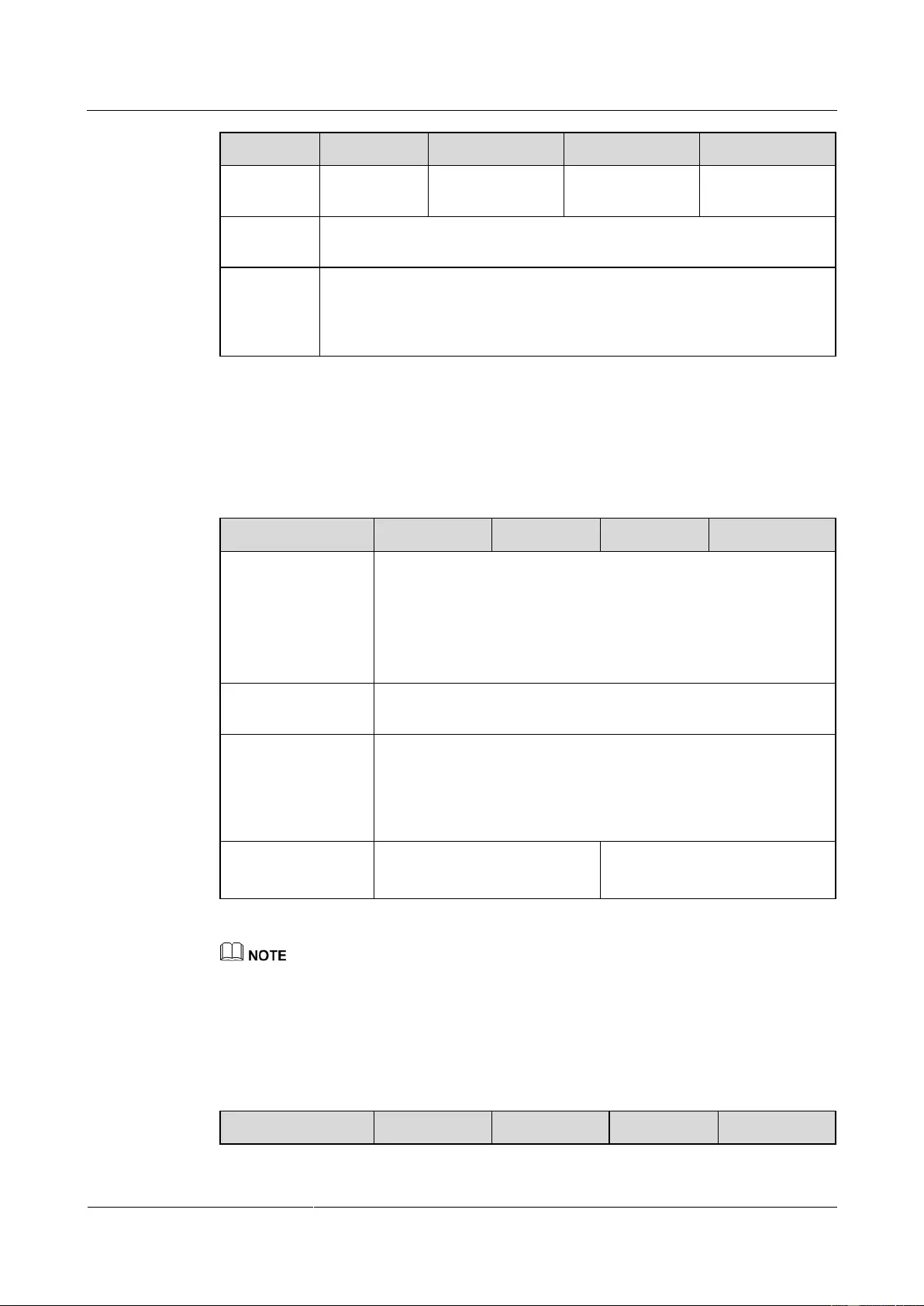
UPS2000-G-(6 kVA-20 kVA)
User Manual
9 Technical Specifications
Copyright © Huawei Technologies Co., Ltd.
Diesel
generator
input
capacity
Minimum 1.5 times the UPS rated capacity
9.4 Bypass Input Electrical Specifications
Table 9-4 Bypass input electrical specifications
Upper threshold: 10%/15%/20%/25%@220 V AC
Upper threshold: 10%/15%/20%@230 V AC
Upper threshold: 10%/15%@240 V AC
Lower threshold: 10%/20%/30%/40%/50%/60%
Bypass frequency
tolerance
Maximum ±6 Hz (configurable on the LCD)
Bypass overload
capability
Load < 125%: continuous in bypass mode
125% ≤ load < 150%: 1 minute in bypass mode
Load ≥ 150%: 100 milliseconds in bypass mode
The input switch may trip in advance.
One mains input
Two mains inputs
The upper and lower thresholds are configurable on the LCD.
9.5 Output Electrical Specifications
Table 9-5 Output electrical specifications
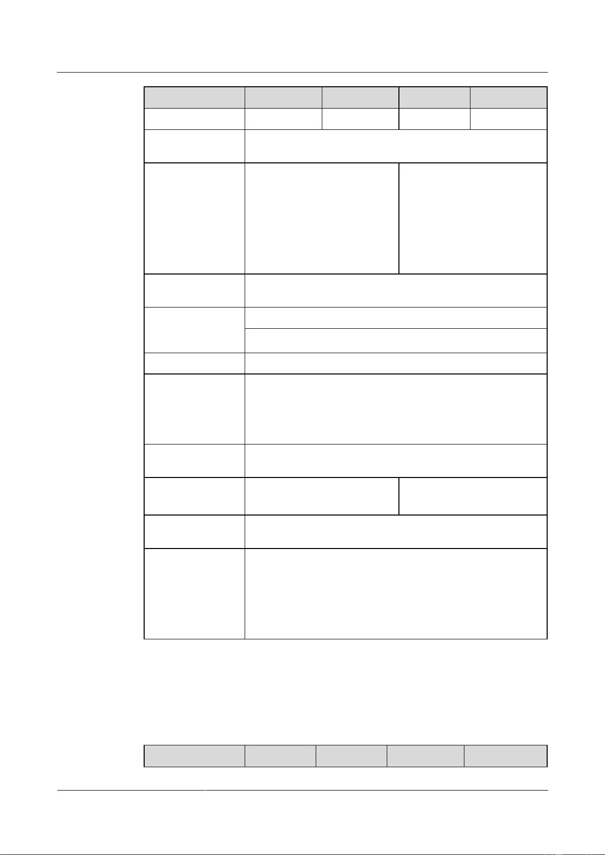
UPS2000-G-(6 kVA-20 kVA)
User Manual
9 Technical Specifications
Copyright © Huawei Technologies Co., Ltd.
220 V AC, 230 V AC, or 240 V
AC (single-phase output; select a
voltage system by setting a
voltage level on the LCD.)
220 V AC, 230 V AC, or 240 V
AC (single-phase output; select
a voltage system by setting a
voltage level on the LCD.)
380 V AC, 400 V AC, or 415 V
AC (three-phase output; select
a voltage system by setting a
voltage level on the LCD.)
Total harmonic
distortion of output
voltage (THDv)
Inverter overload
capability
105% ≤ load < 125%: transfer to bypass mode after 5 minutes
125% ≤ load < 150%: transfer to bypass mode after 1 minute
Load ≥ 150%: transfer to bypass mode after 100 milliseconds
The UPS stops supplying power if the bypass is abnormal.
Dynamic voltage
tolerance
±1% (balanced load)
±3% (unbalanced load)
Average frequency
tracking rate
0.5–2 Hz/s (single UPS) or 0.5–1 Hz/s (parallel system)
Power segment
(only in single UPS
mode)
If overloaded, the UPS disconnects from secondary loads and
checks whether it is still overloaded.
In battery mode, the UPS disconnects from secondary loads if
the battery voltage is less than the specified value.
In battery mode, the UPS disconnects from secondary loads if
the discharge time is more than the specified value.
9.6 Battery Specifications
Table 9-6 Battery specifications
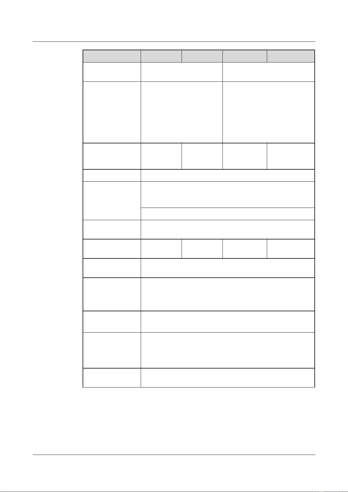
UPS2000-G-(6 kVA-20 kVA)
User Manual
9 Technical Specifications
Copyright © Huawei Technologies Co., Ltd.
16–20, each 12 V DC. If the
smaller value between the
numbers of batteries, N, is less
than 20, the battery power is
derated to N/20.
16–20, respectively in the positive
and negative battery strings. The
rated number is 20. If the smaller
value between the numbers of
batteries in the positive and
negative battery strings, N, is less
than 20, the battery power is
derated to N/20.
Battery string
sharing in a parallel
system
Depth of discharge
(DOD) protection
The discharge time is longer than 16 hours (can be set to 0–24
hours, 16 hours by default. If the time is set to 0 hours, battery
discharge protection is not implemented).
The single-battery voltage drops below 10.8 V in normal mode.
Standard-UPS
battery type
Standard-UPS
battery capacity
> 4 minutes (at full rated load), Figure 9-1, Figure 9-2, Figure 9-3,
and Figure 9-4 show the battery pack backup time.
Batter strings can be connected in parallel. If the user prepares
batteries, the maximum number of battery strings in parallel is
specified by the battery manufacturer. A maximum of four battery
strings are recommended.
Charger rated charge
current
2 A (tolerance ±0.5) for standard models
4 A (tolerance ±0.5) for long backup time models
Batteries are charged to more than 90% in 3 hours for
UPS2000-G-6 kVA/10 kVA standard models.
It depends on battery capacity for UPS2000-G-6 kVA/10 kVA
long backup time models and UPS2000-G-15 kVA/20 kVA.
Charger rated charge
voltage
Each cell has an equalized voltage of 2.35 V and a float voltage of
2.25 V. Both are configurable on the LCD.
UPS2000-G-(6 kVA-20 kVA)
User Manual
9 Technical Specifications
Copyright © Huawei Technologies Co., Ltd.
The parameters in Figure 9-1, Figure 9-2, Figure 9-3, and Figure 9-4 are provided based
on the new battery pack used first.
The ESS-240V12-7AhBPVBA01 part number is 02310PFD.
The ESS-240V12-9AhBPVBA01part number is 02310MWN.
Table 9-7 Backup time parameters for the ESS-240V12-7AhBPVBA01 battery pack (6 kVA,
battery efficiency assumed as 94%)
Three
Battery
packs
(min)
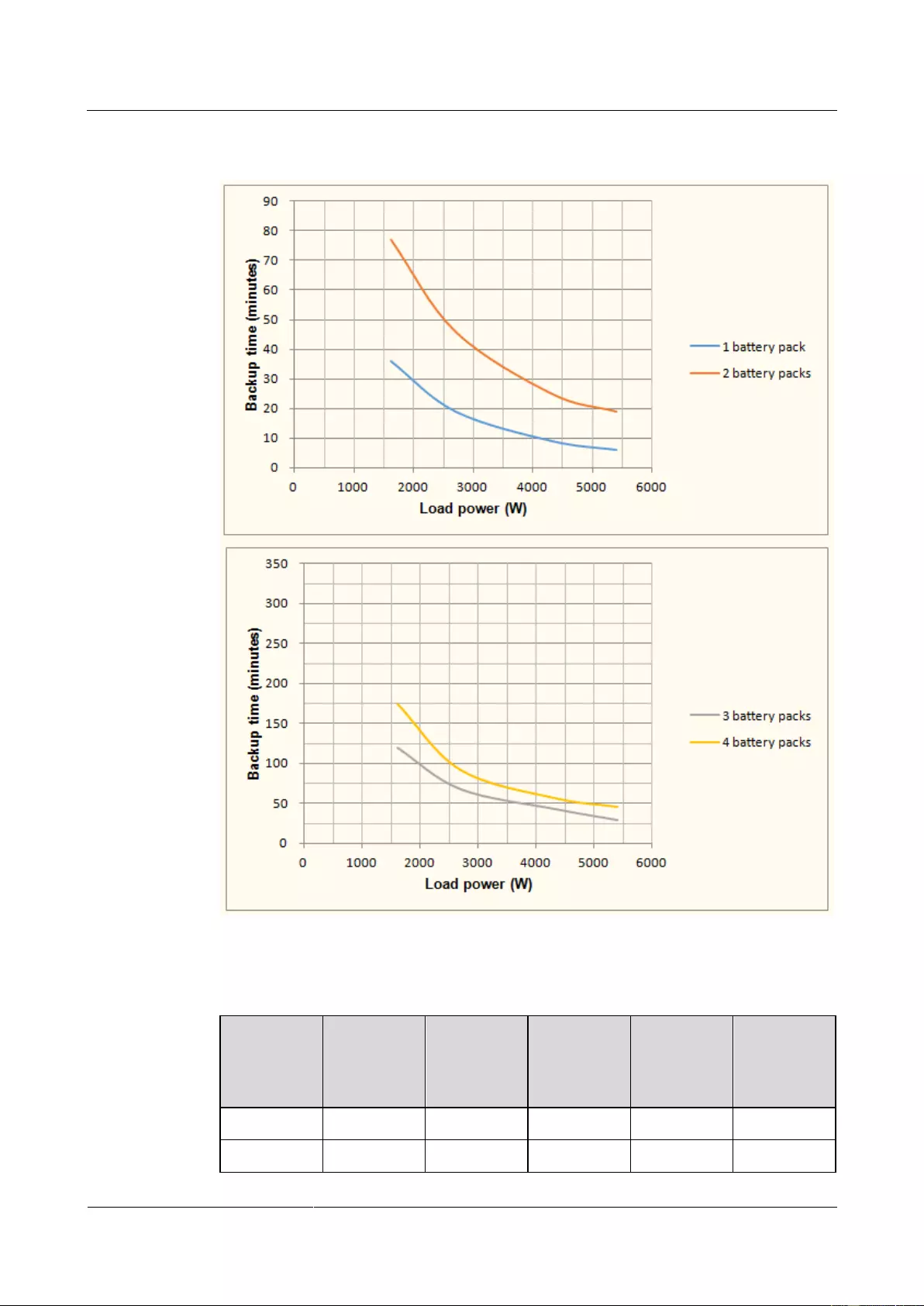
UPS2000-G-(6 kVA-20 kVA)
User Manual
9 Technical Specifications
Copyright © Huawei Technologies Co., Ltd.
Figure 9-1 Backup time parameters for the ESS-240V12—7AhBPVBA01 battery pack (6 kVA,
battery efficiency assumed as 94%)
Table 9-8 Backup time parameters for the ESS-240V12-9AhBPVBA01 battery pack (10 kVA,
battery efficiency assumed as 94%)
Three
Battery
packs
(min)
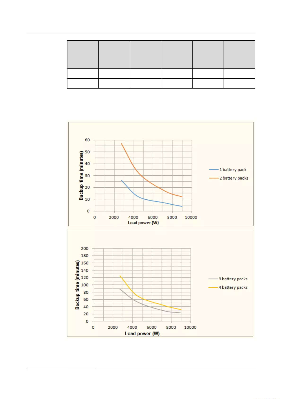
UPS2000-G-(6 kVA-20 kVA)
User Manual
9 Technical Specifications
Copyright © Huawei Technologies Co., Ltd.
Three
Battery
packs
(min)
Figure 9-2 Backup time parameters for the ESS-240V12—9AhBPVBA01 battery pack (10 kVA,
battery efficiency assumed as 94%)
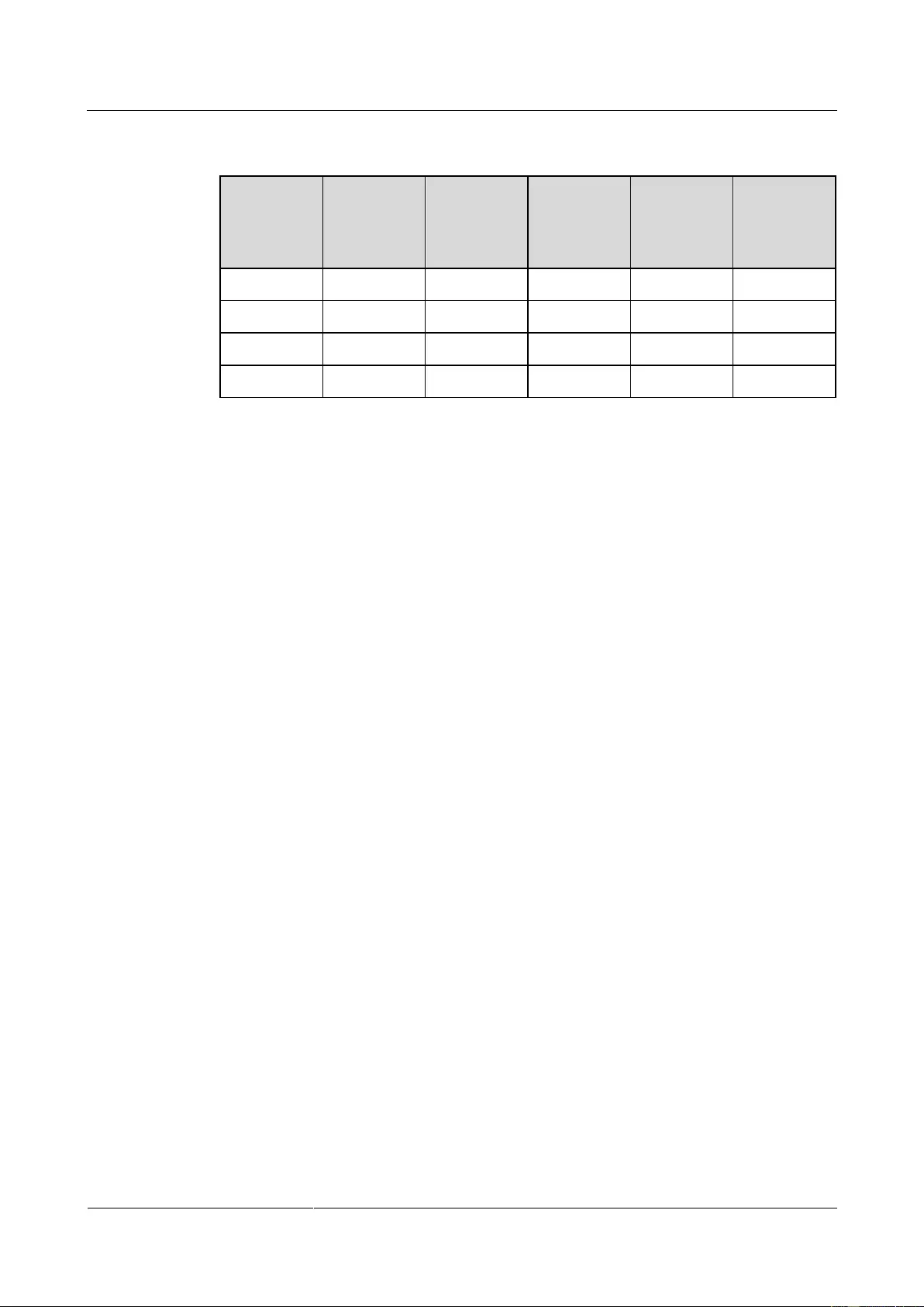
UPS2000-G-(6 kVA-20 kVA)
User Manual
9 Technical Specifications
Copyright © Huawei Technologies Co., Ltd.
Table 9-9 Backup time parameters for the ESS-240V12-9AhBPVBA01 battery pack (15 kVA,
battery efficiency assumed as 94%)
Eight
Battery
packs
(min)
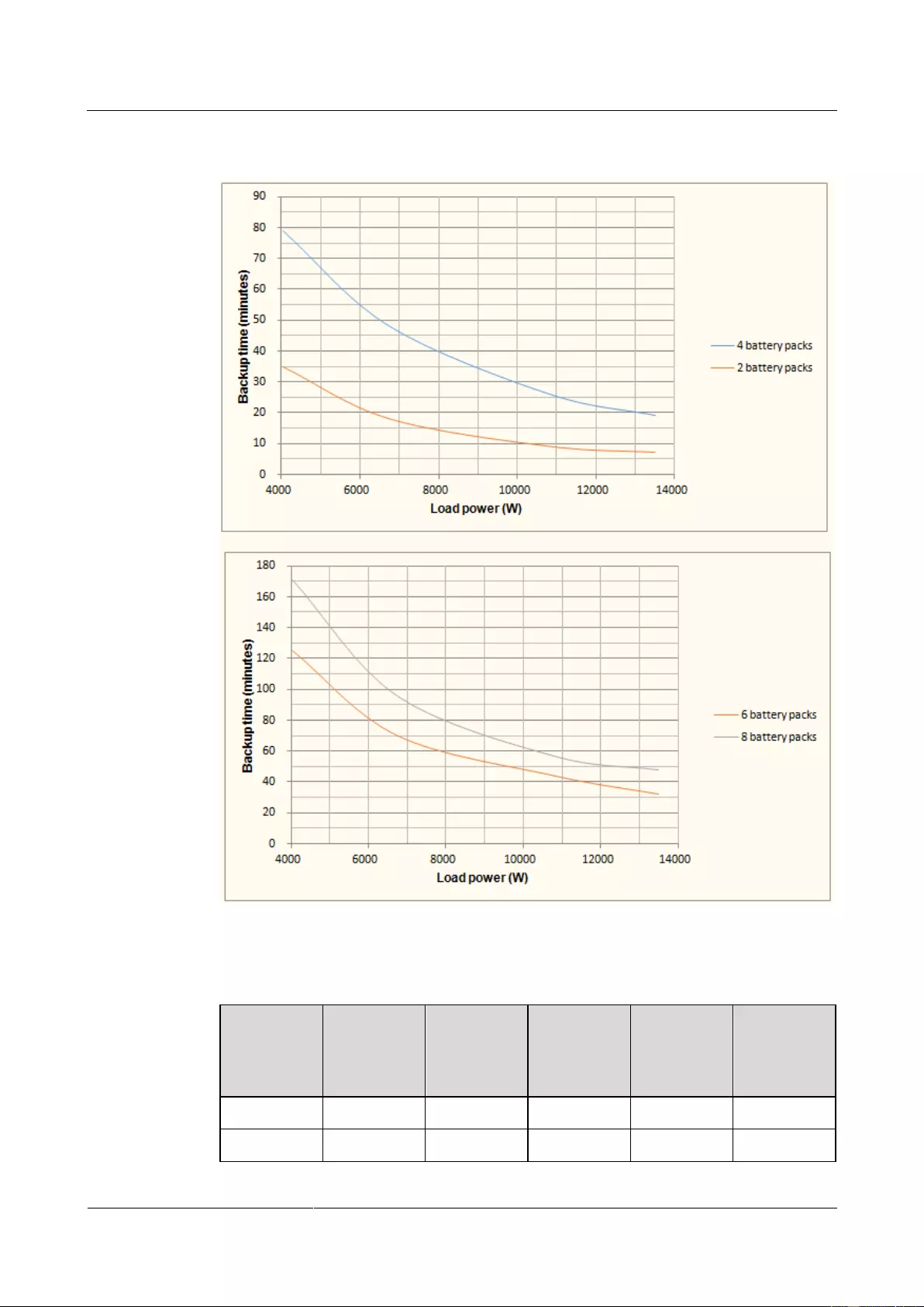
UPS2000-G-(6 kVA-20 kVA)
User Manual
9 Technical Specifications
Copyright © Huawei Technologies Co., Ltd.
Figure 9-3 Backup time parameters for the ESS-240V12—9AhBPVBA01 battery pack (15 kVA,
battery efficiency assumed as 94%)
Table 9-10 Backup time parameters for the ESS-240V12-9AhBPVBA01 battery pack (20 kVA,
battery efficiency assumed as 94%)
Eight
Battery
packs
(min)
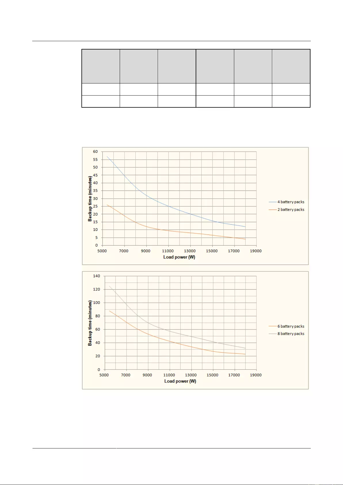
UPS2000-G-(6 kVA-20 kVA)
User Manual
9 Technical Specifications
Copyright © Huawei Technologies Co., Ltd.
Eight
Battery
packs
(min)
Figure 9-4 Backup time parameters for the ESS-240V12—9AhBPVBA01 battery pack (20 kVA,
battery efficiency assumed as 94%)
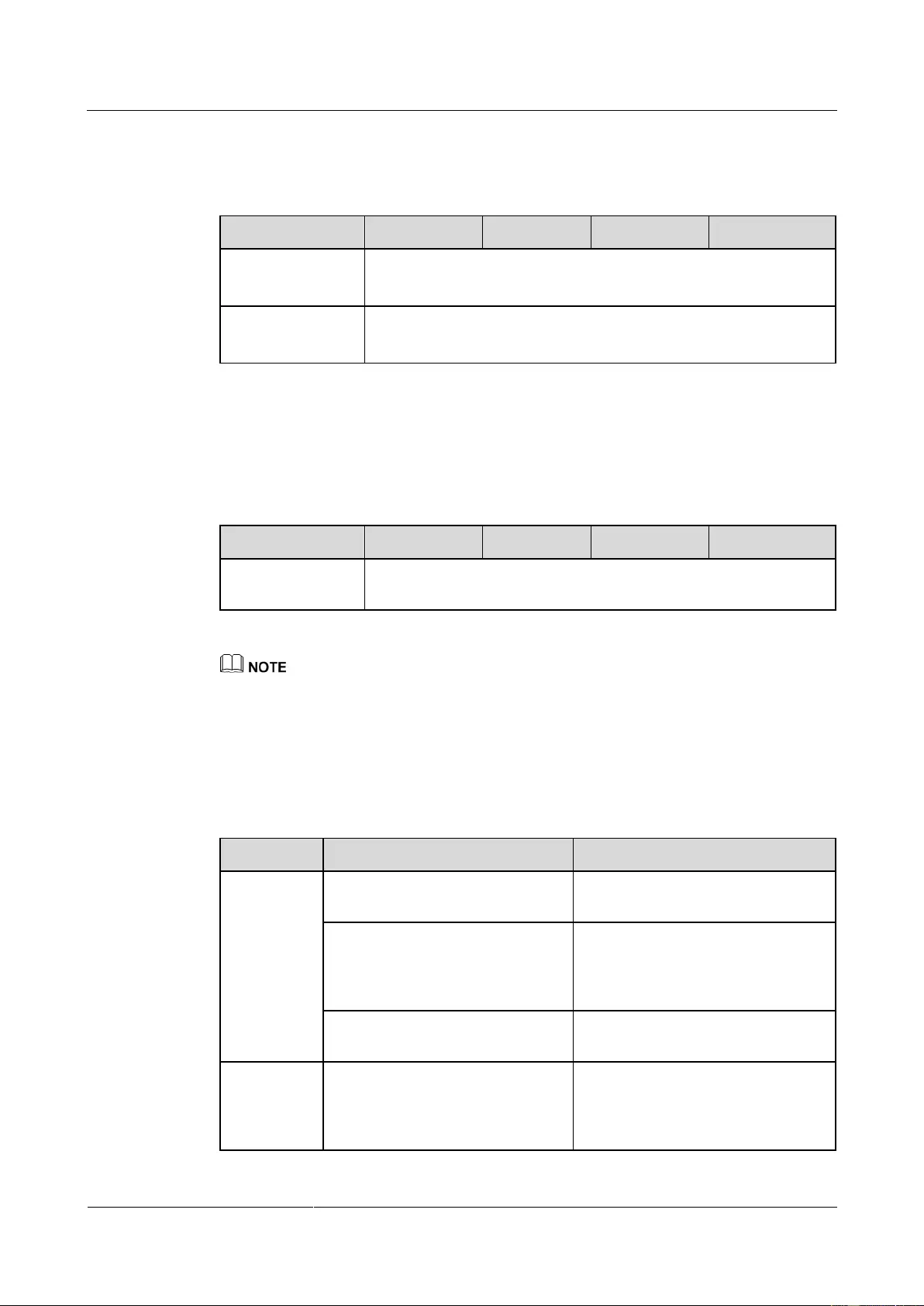
UPS2000-G-(6 kVA-20 kVA)
User Manual
9 Technical Specifications
Copyright © Huawei Technologies Co., Ltd.
9.7 ECO Feature
Table 9-11 ECO feature
Default value: ±10% (configurable on the LCD)
The range is ±5% to 10%
Default value: ±2 Hz (configurable on the LCD)
The range is ±0.5 Hz to ±3 Hz
9.8 Parallel Feature
Table 9-12 Parallel feature
Number of UPSs in
parallel
The UPS2000-G-15 kVA/20 kVA (single-phase input single-phase output) supports 3+1 parallel systems
at most, instead of 4+0 parallel systems.
9.9 Safety Regulations and EMC
Table 9-13 Safety regulations and EMC
Electromagn
etic
compatibilit
y
Conducted radiation:
IEC/EN62040-2
Voltage change, fluctuations, and
flicker I ≤ 16 A,
IEC/EN61000-3-3; 16 A < I ≤ 75
A, IEC/EN61000-3-11
Harmonic interference: 16 A < I ≤
75 A, IEC/EN61000-3-12
Impact
current
(lightning
protection)
IEC/EN60240-2
IEC/EN61000-4-5
YD/T1095-2000 YD/T944-2007
The AC input side meets Level D
lightning protection (differential
mode and common mode: 5 kA and
8/20 µs).
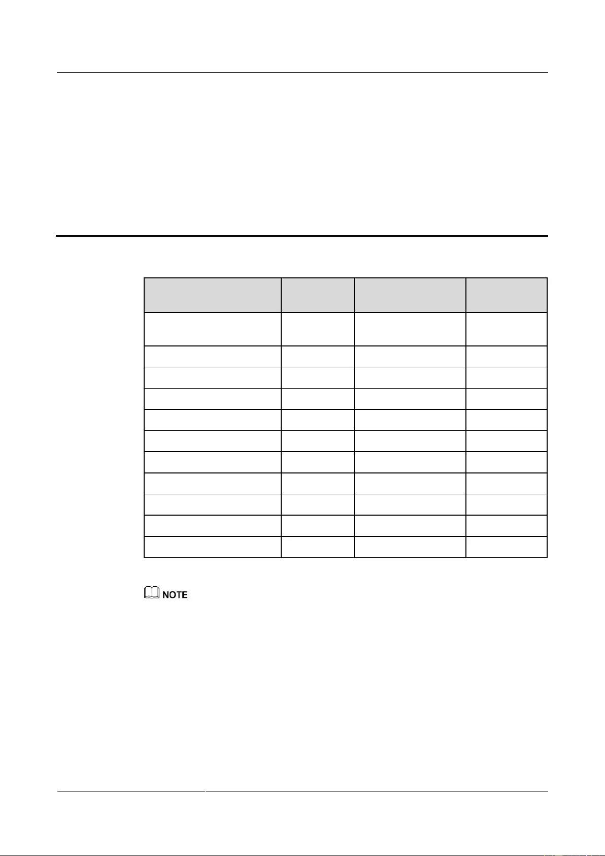
UPS2000-G-(6 kVA-20 kVA)
User Manual
A Parallel Parameter List
Copyright © Huawei Technologies Co., Ltd.
A Parallel Parameter List
Parallel system redundant
UPSs
Self-load output power ratio
You can set parameters on one UPS, and then synchronize the parameters to the other UPSs.
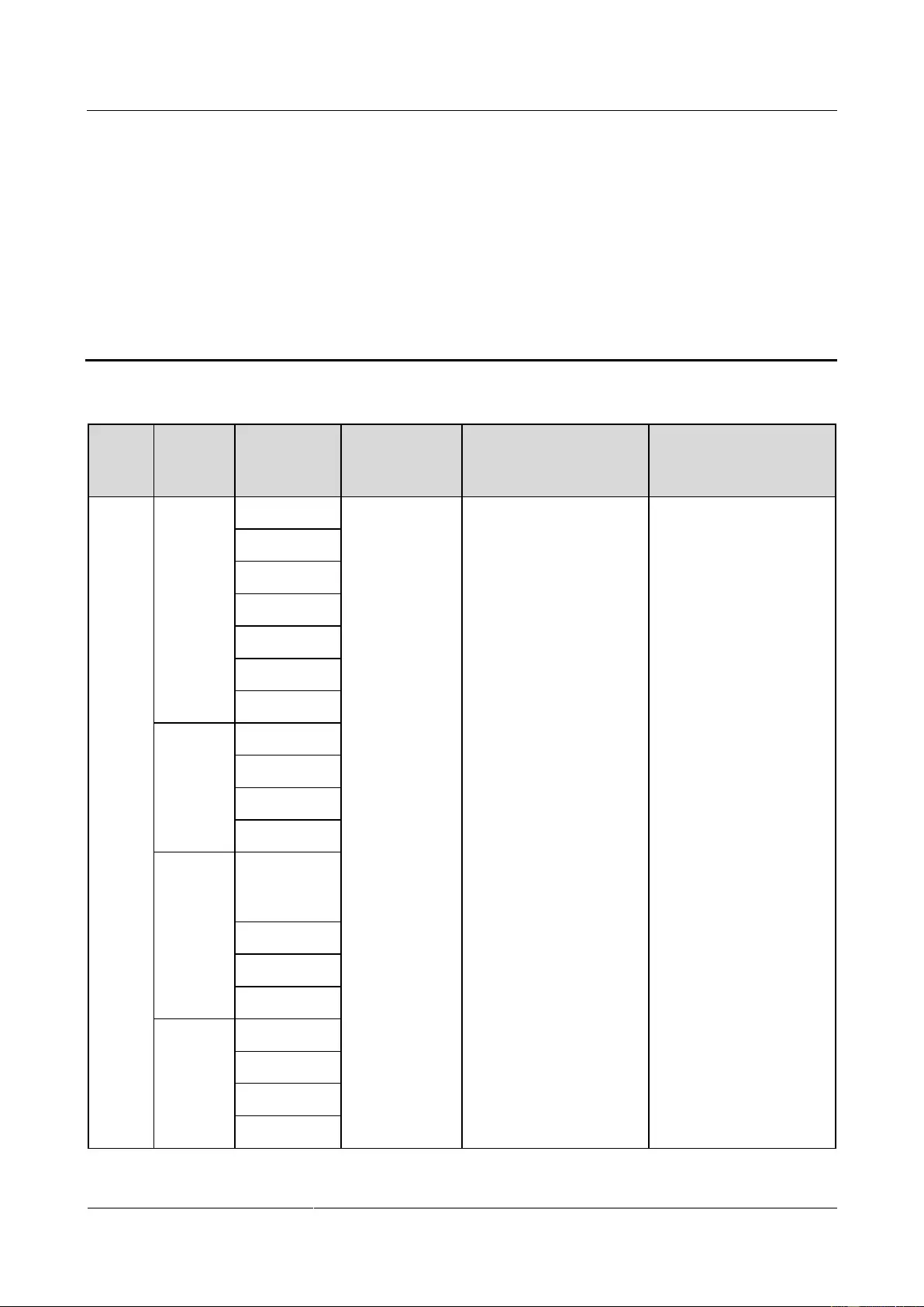
UPS2000-G-(6 kVA-20 kVA)
User Manual
B LCD Menus and Parameters
Copyright © Huawei Technologies Co., Ltd.
B LCD Menus and Parameters
Battery
voltage/Batte
ry current
UPS2000-G-(6 kVA-20 kVA)
User Manual
B LCD Menus and Parameters
Copyright © Huawei Technologies Co., Ltd.
Single UPS
Running/N+
X
Parallel-Syst
em
Single UPS
Running/N+
X
Parallel-Syst
em
UPS2000-G-(6 kVA-20 kVA)
User Manual
B LCD Menus and Parameters
Copyright © Huawei Technologies Co., Ltd.
Occurrence
(latest first)
English, Chinese,
Turkish, French, and
Russian

UPS2000-G-(6 kVA-20 kVA)
User Manual
B LCD Menus and Parameters
Copyright © Huawei Technologies Co., Ltd.
Communicati
on address
(Modbus
Card)
Normal
mode (Dry
contact)
Battery mode
(Dry contact)
Bypass mode
(Dry contact)
Batt.
undervolt
(Dry contact)
BPS
backfeed
(Dry contact)
Parallel
(configurable
after the
inverter shuts
down)
Output
(configurable
after the
inverter shuts
down)
Output mode
(configurable
only on the
UPS2000-G-15
kVA/20 kVA)
Three-phase (on the
UPS2000-G-15 kVA/20
kVA)
220 V, 230 V, and
240 V (on the
UPS2000-G-6
kVA/10 kVA)
220 V (on the
UPS2000-G-6
kVA/10 kVA)
220 V, single-phase
UPS2000-G-(6 kVA-20 kVA)
User Manual
B LCD Menus and Parameters
Copyright © Huawei Technologies Co., Ltd.
220 V, 230 V, and
240 V, single-phase
(on the
UPS2000-G-15
kVA/20 kVA)
380 V, 400 V, and
415 V, three-phase
(on the
UPS2000-G-15
kVA/20 kVA)
(on the
UPS2000-G-15
kVA/20 kVA)
380 V, three-phase
(on the
UPS2000-G-15
kVA/20 kVA)
50 Hz, 60 Hz, and
Automatic
±5%, ±4%, ±3%, ±2%,
±1%, and 0%
Bypass
(configurable
after the
inverter shuts
down)
10%, 15%, 20%, 25%,
and 30%
10%, 20%, 30%, 40%,
50%, and 60%
±0.5 Hz, ±1 Hz, ±2 Hz,
±3 Hz, ±4 Hz, ±5 Hz, and
±6 Hz
ECO
(configurable
after the
inverter shuts
down)
5%, 6%, 7%, 8%, 9%,
and 10%
5%, 6%, 7%, 8%, 9%,
and 10%
±0.5 Hz, ±1 Hz, ±2 Hz,
and ±3 Hz
Dis. time thres.
(configurable
in non-battery
mode)
Dis. volt. thres.
(configurable
in non-battery
mode)
Power Segment
(configurable

UPS2000-G-(6 kVA-20 kVA)
User Manual
B LCD Menus and Parameters
Copyright © Huawei Technologies Co., Ltd.
after the
inverter shuts
down)
Self-Load
(configurable
after the
inverter shuts
down)
Others
(configurable
after the
inverter shuts
down)
Weak adaptability mode,
Balanced mode, and
Strong adaptability mode
No battery
alarm
(configurable
only when
batteries are not
connected)
Batteries
/Positive
batteries/Negati
ve batteries
(configurable
in non-battery
mode)
Battery
capacity
(configurable
in non-battery
mode)
For the UPS2000-G-6
kVA, the default
value is 7 Ah on a
standard model and 40
Ah on a long backup
time model.
For the
UPS2000-G-10 kVA,
the default value is 9
Ah on a standard
model and 65 Ah on a
UPS2000-G-(6 kVA-20 kVA)
User Manual
B LCD Menus and Parameters
Copyright © Huawei Technologies Co., Ltd.
long backup time
model.
For the
UPS2000-G-15
kVA/20 kVA, the
default value is 65 Ah
on a long backup time
model.
2.0–4.0 A (standard
model)
4.0–8.0 A (long
backup time model)
3.0 A (standard
model)
6.0 A (long backup
time model)
1.0–2.0 A (standard
model)
1.0–4.0 A (long
backup time model)
Max. time
(configurable
in non-battery
mode)
EOD mode
(configurable
in non-battery
mode)
Batt. protect first, Backup
time first, and Balanced
mode
EOD auto-start
(configurable

UPS2000-G-(6 kVA-20 kVA)
User Manual
B LCD Menus and Parameters
Copyright © Huawei Technologies Co., Ltd.
after the
inverter shuts
down)
Settings
wizard
(configur
able after
the
inverter
shuts
down)
English, Chinese,
Spanish, French, and
Russian
220 V, 230 V, and
240 V (on the
UPS2000-G-6
kVA/10 kVA)
220 V, 230 V, and
240 V, single-phase
(on the
UPS2000-G-15
kVA/20 kVA)
380 V, 400 V, and
415 V, three-phase
(on the
UPS2000-G-15
kVA/20 kVA)
220 V (on the
UPS2000-G-6
kVA/10 kVA)
220 V, single-phase
(on the
UPS2000-G-15
kVA/20 kVA)
380 V, three-phase
(on the
UPS2000-G-15
kVA/20 kVA)
50 Hz, 60 Hz, and
Automatic
Output mode
(configurable
only on the
UPS2000-G-15
kVA/20 kVA)
Single-phase and
Three-phase
Three-phase (on the
UPS2000-G-15 kVA/20
kVA)
Batteries
/Positive
batteries/Negati
ve batteries
For the UPS2000-G-6
kVA, the default
value is 7 Ah on a
standard model and 40
Ah on a long backup
time model.
UPS2000-G-(6 kVA-20 kVA)
User Manual
B LCD Menus and Parameters
Copyright © Huawei Technologies Co., Ltd.
For the
UPS2000-G-10 kVA,
the default value is 9
Ah on a standard
model and 65 Ah on a
long backup time
model.
For the
UPS2000-G-15
kVA/20 kVA, the
default value is 65 Ah
on a long backup time
model.
Restore
Default
Settings
(configur
able after
the
inverter
shuts
down)
Manual
Equalized
Charging/Ma
nual EC for
Pos.
/ManualEC
for Pos.
Manual Float
Charging/Ma
nual FC for
Neg.
UPS2000-G-(6 kVA-20 kVA)
User Manual
B LCD Menus and Parameters
Copyright © Huawei Technologies Co., Ltd.
The bypass frequency range is associated with the ECO frequency range (the bypass frequency
range is ±0.5 Hz, ±1 Hz, ±2 Hz, ±3 Hz, ±4 Hz, ±5 Hz, or ±6 Hz; the ECO frequency range is ±0.5
Hz, ±1 Hz, ±2 Hz, or ±3 Hz).
The bypass frequency range must be greater than or equal to the current ECO frequency range (if the
ECO frequency range is ±3 Hz, the bypass frequency range is ±3 Hz, ±4 Hz, ±5 Hz, or ±6 Hz).
The ECO frequency range must be less than or equal to the current bypass frequency range (if the
bypass frequency range is ±1 Hz, the ECO frequency range is ±0.5 Hz or ±1 Hz).
The voltage level is associated with the upper threshold for bypass voltages (10%, 15%, 20%, 25%,
or 30%).
If the voltage level is 220 V (line voltage: 380 V), the upper threshold for bypass voltages is 10%,
15% (default), 20%, or 25%.
If the voltage level is 230 V (line voltage: 400 V), the upper threshold for bypass voltages is 10%,
15% (default), or 20%.
If the voltage level is 240 V (line voltage: 415 V), the upper threshold for bypass voltages is 10% or
15% (default).

UPS2000-G-(6 kVA-20 kVA)
User Manual
Copyright © Huawei Technologies Co., Ltd.
C Alarm Handling
Alarm
ID
(Alarm
ID-Alar
m
Cause)
The UPS transfers to
battery mode.
If no battery is
equipped, the UPS
shuts down.
Possible causes:
The mains voltage exceeds
280 V.
The mains voltage is less than
80 V.
The mains frequency is not in
the range of 40 Hz to 70 Hz.
Measures:
Check whether the mains
input voltage is less than 272
V. If not, wait until the mains
recovers.
Check whether the mains
input voltage is greater than
88 V. If not, wait until the
mains recovers.
Check the mains input
frequency. If the mains input
frequency is abnormal, wait
until the mains input recovers.
The rectifier transfers
to battery mode,
without affecting the
power supply.
If no batteries are
installed, the UPS shuts
down.
The UPS may transfer
Possible cause: The mains input
three-phase sequence is incorrect.
Measure: Check that mains input
power cables are correctly
connected.

UPS2000-G-(6 kVA-20 kVA)
User Manual
Copyright © Huawei Technologies Co., Ltd.
Alarm
ID
(Alarm
ID-Alar
m
Cause)
to another working
mode or shut down.
The UPS transfers to
battery mode.
If no battery is
equipped, the UPS
shuts down.
The UPS changes the
working mode or shuts
down.
Possible cause: The mains input
neutral wire is not connected.
Measure: Check that mains input
power cables are correctly
connected.
Manual
clear/Po
wer-off
clear/Aut
omatic
clear
The UPS does not transfer
back to normal mode even
when the mains is normal.
Possible cause: The mains
voltage fluctuates frequently. The
UPS has transferred from normal
mode to battery mode within 2
minutes for 10 consecutive times.
The rectifier locks out in battery
mode.
Measure: Check the mains.
Manual
clear/Po
wer-off
clear
Possible cause: The mains
voltage frequently becomes
abnormal during startup.
Measure: Check the mains input
voltage. If the voltage becomes
normal, clear the alarm and
restart the UPS.
The UPS cannot transfer to
bypass mode. If the bypass
is supplying power, the
UPS changes the working
mode.
Possible causes:
The bypass input voltage is
abnormal.
The bypass input frequency is
abnormal.
Measures:
Check whether the bypass
input voltage exceeds the
configured range. If yes,
change the range or wait until
the bypass input recovers.
Check whether the bypass
input frequency exceeds the
configured range. If yes,
change the range or wait until
the bypass input recovers.

UPS2000-G-(6 kVA-20 kVA)
User Manual
Copyright © Huawei Technologies Co., Ltd.
Alarm
ID
(Alarm
ID-Alar
m
Cause)
If the inverter has not
started, the system has
no output, and inverter
startup is prohibited.
If the inverter has
started, the inverter still
works properly, but the
system cannot transfer
to bypass mode.
Possible cause: The bypass input
three-phase sequence is incorrect.
Measure: Check that bypass input
power cables are correctly
connected.
If the inverter has not
started, the system has no
output, and inverter startup
is prohibited.
If the inverter has started,
the inverter still works
properly, but the system
cannot transfer to bypass
mode.
Possible cause: The bypass input
neutral wire is not connected.
Measures: Check that bypass
input power cables are correctly
connected.
Manual
clear/Po
wer-off
clear
Possible causes:
The bypass load exceeds the
rated inverter load.
An internal fault occurs in the
UPS.
Measures:
Reduce the output load,
manually clear the alarm, and
restart the UPS.
Contact Huawei technical
support for repair.
The power supply from the
UPS and system is not
affected.
Possible cause: Batteries are
reversely connected.
Measure: Check the battery
installation, and reinstall the
batteries.
The power supply from the
UPS and system is not
affected.
Possible causes:
Batteries are not connected.
Batteries are not securely
connected.
Measures:
Connect batteries.

UPS2000-G-(6 kVA-20 kVA)
User Manual
Copyright © Huawei Technologies Co., Ltd.
Alarm
ID
(Alarm
ID-Alar
m
Cause)
Check that batteries are
securely connected.
An alarm is generated, and
the battery lifespan is
affected.
Possible causes:
The ambient temperature
exceeds the battery high
temperature alarm threshold
(default value: 50ºC)
The battery charge/discharge
current exceeds the upper
threshold.
Measures:
Install more cooling
equipment such as air
conditioners.
Control the battery
charge/discharge current by
reducing loads.
An alarm is generated, and
the battery lifespan is
affected.
Possible causes:
The configured number of
batteries is less than the actual
number.
The battery string charge
voltage exceeds the upper
threshold.
Measures:
Check battery parameter
settings.
Disconnected the external
battery charger, check
whether the alarm is cleared.
If not, contact Huawei
technical support for repair.
An alarm is generated, and
the system may shut down
due to EOD.
Possible cause: The mains input
is abnormal. Battery discharge
results in a low battery voltage.
Measure: If possible, connect to
the mains power when the UPS is
in non-battery test state.
An alarm is generated, and
the battery lifespan is
affected.
Possible causes: The charger is
abnormal.
Measure: Contact Huawei

UPS2000-G-(6 kVA-20 kVA)
User Manual
Copyright © Huawei Technologies Co., Ltd.
Alarm
ID
(Alarm
ID-Alar
m
Cause)
technical support for repair.
Possible causes:
The mains input power cables
are incorrectly connected.
The mains input circuit
breaker is OFF.
Measure: Check whether mains
input power cables are correctly
connected. If yes, switch on the
mains input circuit breaker.
Possible causes:
The bypass is short-circuited
or the bypass input
experiences overcurrent.
The bypass input circuit
breaker is OFF.
Measures:
Check whether the bypass
output load is short-circuited
using a multimeter.
Check whether cable
connections are correct. If
yes, switch on the bypass
input circuit breaker.
Possible causes:
The bypass is short-circuited
or the bypass input
experiences overcurrent.
The bypass input circuit
breaker is OFF.
Measures:
Check whether the circuit
breaker downstream load is
short-circuited using a
multimeter.
Check whether cable
connections are correct. If
yes, switch on the output
circuit breaker.
The battery backup time is

UPS2000-G-(6 kVA-20 kVA)
User Manual
Copyright © Huawei Technologies Co., Ltd.
Alarm
ID
(Alarm
ID-Alar
m
Cause)
The battery capacity is
incorrectly set.
The battery loop cannot be
discharged.
The battery capacity is low.
Measures:
Check whether the configured
battery capacity matches the
connected battery capacity.
Check battery connections
and the status of each battery.
Contact Huawei technical
support for repair.
The power supply from the
UPS and system is not
affected.
Possible causes:
The ambient temperature
exceeds 40°C.
The air channel is blocked.
The fan is abnormal.
Measures:
Decrease the ambient
temperature.
Keep the air intake and
exhaust vents of the UPS
unobstructed.
Clean off the foreign objects
around the fan. If the alarm
persists, contact Huawei
technical support for repair.
An alarm is generated, and
the battery lifespan is
affected.
Possible causes:
The configured number of
batteries is less than the actual
number.
The actual number of batteries
does not meet specifications.
The charger is abnormal.
Measures:
Check that the configured
number of batteries matches
the actual number.
Check that the actual number

UPS2000-G-(6 kVA-20 kVA)
User Manual
Copyright © Huawei Technologies Co., Ltd.
Alarm
ID
(Alarm
ID-Alar
m
Cause)
of batteries meets
requirements.
Disconnected the external
battery charger, check
whether the alarm is cleared.
If not, contact Huawei
technical support for repair.
If no action is taken,
continued discharge will
result in system shutdown
due to EOD.
Possible cause:
The battery discharge lasts too
long.
The mains input is abnormal.
The number of batteries or
battery capacity is incorrectly
set.
Measure:
Check the mains, and charge
batteries in a timely manner.
Check the configured battery
capacity.
An alarm is generated. If
the shallow discharge test
is not performed for a long
time, the battery power
backup function may be
affected.
Possible cause: The battery does
not experience shallow discharge,
and the maintenance period
expires.
Measure:
Perform the following steps:
Click the alarm. The battery
maintenance menu is displayed.
Perform a shallow discharge test.
The alarm will be automatically
cleared no matter whether test
conditions are met.
Manual
clear/Po
wer-off
clear
The UPS shuts down.
The UPS transfers to
another working mode or
shuts down.
Possible cause: The soft-start
resistor is damaged.
Measure: Contact Huawei
technical support for repair.
Manual
clear/Po
wer-off
clear
The UPS cannot be started.
Possible causes:
The mains input harmonic is
large.
The rectifier startup circuit is
damaged.

UPS2000-G-(6 kVA-20 kVA)
User Manual
Copyright © Huawei Technologies Co., Ltd.
Alarm
ID
(Alarm
ID-Alar
m
Cause)
Measures:
After you rectify the fault,
restart the UPS.
Contact Huawei technical
support for repair.
Manual
clear/Po
wer-off
clear/Aut
omatic
clear
The UPS shuts down.
The UPS transfers to
another working mode or
shuts down.
Possible causes:
The mains experiences
instantaneous high-voltage
impact.
The output has special loads
such as inductive loads and
rectification loads.
The output has transformer
loads but the transformer
mode is not set.
The hardware is damaged.
Measures:
After you rectify the fault,
restart the UPS.
Check whether the load type
is supported by the UPS.
Enable the transformer mode.
Contact Huawei technical
support for repair.
Manual
clear/Po
wer-off
clear/Aut
omatic
clear
The UPS shuts down.
The UPS transfers to
another working mode or
shuts down.
Possible cause: The hardware is
damaged.
Measure: Contact Huawei
technical support for repair.
The UPS shuts down.
The UPS transfers to
another working mode or
shuts down.
Possible cause: The hardware is
damaged.
Measure: Contact Huawei
technical support for repair.
The UPS shuts down.
The UPS transfers to
another working mode or
shuts down.
The charger stops
working.
Possible causes:
The ambient temperature
exceeds 40°C.
The air channel is blocked.
The fan is abnormal.

UPS2000-G-(6 kVA-20 kVA)
User Manual
Copyright © Huawei Technologies Co., Ltd.
Alarm
ID
(Alarm
ID-Alar
m
Cause)
Measures:
Decrease the ambient
temperature.
Keep the air intake and
exhaust vents of the UPS
unobstructed.
Clean off the foreign objects
around the fan. If the alarm
persists, contact Huawei
technical support for repair.
The rectifier transfers to
battery mode, and the
power supply is not
affected.
If no battery is installed,
the UPS shuts down.
The UPS transfers to
another working mode or
shuts down.
Possible cause: The rectifier is
faulty.
Measure: Contact Huawei
technical support for repair.
Manual
clear/Po
wer-off
clear
Possible cause: The digital signal
processing (DSP) or complex
programmable logical device
(CPLD) chip is faulty.
Measure: Contact Huawei
technical support for repair.
Manual
clear/Po
wer-off
clear
Possible cause: The EEPROM
chip is faulty.
Measure: Contact Huawei
technical support for repair.
The UPS shuts down.
The UPS may transfer to
another working mode or
shut down.
Possible cause: The single-side
bus capacitor is faulty.
Measure: Contact Huawei
technical support for repair.
Manual
clear/Po
wer-off
clear
The power supply from the
UPS and system is not
affected.
Possible cause: The bus capacitor
is faulty.
Measure: Contact Huawei
technical support for repair.
Possible cause: The load power
exceeds the loading capacity of
the batteries.

UPS2000-G-(6 kVA-20 kVA)
User Manual
Copyright © Huawei Technologies Co., Ltd.
Alarm
ID
(Alarm
ID-Alar
m
Cause)
Measure: Reduce the load power
or verify the number of batteries.
Manual
clear/Po
wer-off
clear
Possible cause: The auxiliary
power source is faulty.
Measure: Contact Huawei
technical support for repair.
Manual
clear/Po
wer-off
clear
Possible cause: The soft-start
resistor is damaged.
Measure: Contact Huawei
technical support for repair.
The power supply from the
UPS and system is not
affected.
Possible cause: The NTC is not
connected or is damaged.
Measure: Contact Huawei
technical support for repair.
Possible cause: Self-load cable
connections are incorrect.
Measure: Reconnect cables.
If the inverter has not
started, the UPS has no
output, and inverter startup
is not allowed.
If the inverter has started,
inverter operation is not
affected, but transfer to
bypass mode is not
allowed.
Possible cause: The bypass input
cable connections do not match
the output system.
Measure: Ensure that the bypass
input cable connections match
the output system.
After the parallel system is
powered on, an incorrect
bypass phase sequence is
detected on a UPS. The
parallel system has not
output.
The parallel system works
in inverter mode. The
newly added UPS has no
output because bypass
cables are incorrectly
connected.
The parallel system works
in bypass mode. The
parallel system has no
Possible cause: The bypass phase
sequences in the parallel system
do not match.
Measure: Check bypass input
phase sequences in the parallel
system.

UPS2000-G-(6 kVA-20 kVA)
User Manual
Copyright © Huawei Technologies Co., Ltd.
Alarm
ID
(Alarm
ID-Alar
m
Cause)
output because bypass
cables for the newly added
UPS are incorrectly
connected.
Manual
clear/Po
wer-off
clear
The UPS startup is not
allowed.
Possible cause: The three-phase
power cable lengths vary greatly.
Measure: Ensure that the lengths
of three-phase power cables vary
within a difference of 5%.
Manual
clear/Po
wer-off
clear
The UPS startup is not
allowed.
Possible cause: The inverter is
faulty.
Measure: Contact Huawei
technical support for repair.
The power supply from the
UPS and system is not
affected.
Possible cause: The fan is
abnormal.
Measure: Clean off the foreign
objects around the fan. If the
alarm persists, contact Huawei
technical support for repair.
The power supply from the
UPS and system is not
affected.
Possible cause: The fan is
abnormal.
Measure: Clean off the foreign
objects around the fan. If the
alarm persists, contact Huawei
technical support for repair.
Manual
clear/Po
wer-off
clear
The UPS startup is not
allowed.
Possible cause: An error occurred
during software loading.
Measure: Contact the
manufacturer to load software.
Manual
clear/Po
wer-off
clear
The UPS startup is not
allowed.
Possible cause: Software and
hardware versions do not match.
Measure: Contact the
manufacturer to load software.
Manual
clear/Po
wer-off
clear
The UPS startup is not
allowed.
Possible cause: Software and
hardware versions do not match.
Measure: Contact the
manufacturer to load software.
The UPS startup is not
allowed.
Possible cause: An error occurred
during software loading.
Measure: Contact the

UPS2000-G-(6 kVA-20 kVA)
User Manual
Copyright © Huawei Technologies Co., Ltd.
Alarm
ID
(Alarm
ID-Alar
m
Cause)
manufacturer to load software.
Manual
clear/Po
wer-off
clear
The UPS startup is not
allowed.
Possible cause: Software and
hardware versions do not match.
Measure: Contact the
manufacturer to load software.
Manual
clear/Po
wer-off
clear
The UPS startup is not
allowed.
Possible cause: Software and
hardware versions do not match.
Measure: Contact the
manufacturer to load software.
Manual
clear/Po
wer-off
clear
The charger in the UPS
stops.
Possible cause: The charger
capacitor is faulty.
Measure: Contact Huawei
technical support for repair.
Possible cause: The charger
output is short-circuited.
Measure: Rectify battery port
short circuits. After you clear the
alarm, restart the UPS. If the
alarm persists, contact Huawei
technical support for repair.
Possible cause: The charger is
faulty.
Measure: Contact Huawei
technical support for repair.
Manual
clear/Po
wer-off
clear
The charger in the UPS
stops.
(The 20 kVA has no
action.)
Possible cause: The charger is
faulty.
Measure: Contact Huawei
technical support for repair.
Manual
clear/Po
wer-off
clear/Aut
omatic
clear
The charger in the UPS
stops.
Manual
clear/Po
wer-off
clear

UPS2000-G-(6 kVA-20 kVA)
User Manual
Copyright © Huawei Technologies Co., Ltd.
Alarm
ID
(Alarm
ID-Alar
m
Cause)
Manual
clear/Po
wer-off
clear/Aut
omatic
clear
An alarm is displayed, and
the battery service life may
be shortened.
Possible causes:
The number of batteries is
incorrectly set.
Batteries are damaged.
If batteries are fully charged,
reconnect the batteries as soon
as the system powers off.
Measures:
Check whether the number of
batteries is correctly set.
Check whether batteries are
damaged.
After ensuring that the
number of batteries is correct,
clear the alarm.
The inverter shuts down.
The UPS transfers to
bypass mode or has no
output based on the
transfer logic.
Possible cause: The inverter is
faulty.
Measure: Contact Huawei
technical support for repair.
The UPS shuts down.
The UPS may transfer to
another working mode or
shut down.
Possible cause: The inverter relay
is faulty.
Measure: Contact Huawei
technical support for repair.
Possible cause: The inverter
output is short-circuited.
Measure: Rectify output port
short circuits. After you clear the
alarm, restart the UPS. If the
alarm persists, contact Huawei
technical support for repair.
Possible causes:
The mains experiences
instantaneous high-voltage
impact.
The output has special loads
such as sensitive loads and
rectification loads.
The output has transformer
loads but the transformer

UPS2000-G-(6 kVA-20 kVA)
User Manual
Copyright © Huawei Technologies Co., Ltd.
Alarm
ID
(Alarm
ID-Alar
m
Cause)
mode is not set.
The hardware is faulty.
Measures:
After you rectify the fault,
restart the UPS.
Check whether the load type
is supported by the UPS.
Enable the transformer mode.
Contact Huawei technical
support for repair.
The UPS starts upon
shutdown.
The UPS may transfer to
another working mode or
shut down.
Possible causes:
The ambient temperature
exceeds 40ºC.
The air channel is blocked.
The fan is abnormal.
Measures:
Decrease the ambient
temperature.
Keep the air intake and
exhaust vents of the UPS
unobstructed.
Clean off the foreign objects
around the fan. If the alarm
persists, contact Huawei
technical support for repair.
Manual
clear/Po
wer-off
clear
Possible cause: The DSP or
CPLD chip is faulty.
Measure: Contact Huawei
technical support for repair.
Manual
clear/Po
wer-off
clear/Aut
omatic
clear
The UPS shuts down.
The UPS may transfer to
another working mode or
shut down.
Possible causes:
Parallel cables are incorrectly
connected.
The lengths of parallel cables
vary greatly.
Measures:
Reconnect cables.
The lengths of parallel cables
vary within a range of 5%.

UPS2000-G-(6 kVA-20 kVA)
User Manual
Copyright © Huawei Technologies Co., Ltd.
Alarm
ID
(Alarm
ID-Alar
m
Cause)
Manual
clear/Po
wer-off
clear
Possible cause: The EEPROM
chip is faulty.
Measure: Contact Huawei
technical support for repair.
The UPS automatically
starts after shutdown.
The UPS transfers to
another working mode or
shuts down.
Possible cause: The load exceeds
the rated inverter loading
capacity.
Measure: Reduce the load or
replace the UPS with a
larger-capacity UPS.
Manual
clear/Po
wer-off
clear
The UPS startup is not
allowed.
Possible cause: The load exceeds
the rated bypass loading capacity.
Measure: Reduce the load or
replace the UPS with a
larger-capacity UPS.
Manual
clear/Po
wer-off
clear
In single UPS mode, the
loads connected to pL
power off.
Possible cause: The load exceeds
the rated loading capacity.
Measure: Reduce the load or
replace the UPS with a
larger-capacity UPS.
Automati
c
clear/Ma
nual
clear
Possible causes:
The battery voltage is below
the battery protection voltage.
The battery discharge time
exceeds the battery protection
time.
Measures:
Check the battery voltage.
Modify the power segment
settings on the LCD.
Continuous overload
causes the UPS to transfer
to bypass mode or supply
no power.
Possible cause: The load exceeds
the rated loading capacity.
Measure: Reduce the load or
replace the UPS with a
larger-capacity UPS.
Continuous overload
causes the UPS to supply
no power.
Possible cause: The load exceeds
the rated bypass loading capacity.
Measure: Reduce the load or
replace the UPS with a

UPS2000-G-(6 kVA-20 kVA)
User Manual
Copyright © Huawei Technologies Co., Ltd.
Alarm
ID
(Alarm
ID-Alar
m
Cause)
UPS startup is not allowed.
Possible cause: The single UPS
and parallel system settings do
not match cable connections.
Measures:
Check the single UPS and
parallel system settings.
Check that parallel cable
connections match the
settings.
The bypass input circuit
breaker in the PDU is
OFF.
Possible cause: The bypass
component is faulty.
Measure: Contact Huawei
technical support for repair.
Manual
clear/Po
wer-off
clear
The UPS shuts down.
The parallel system shuts
down.
Possible causes:
The parallel cable is loose.
The parallel cable is damaged.
Measures:
Check that the parallel cable
is securely connected.
Replace the parallel cable.
Contact Huawei technical
support for repair.
Manual
clear/Po
wer-off
clear/Aut
omatic
clear
The UPS shuts down.
The parallel system
transfers to another
working mode.
Possible causes:
The parallel cable is loose.
The parallel cable is damaged.
Measures:
Check that the parallel cable
is securely connected.
Replace the parallel cable.
Contact Huawei technical
support for repair.
Manual
clear/Po
wer-off
clear
Possible cause: The EPO button
is pressed.
Measure: Restore the EPO button
status. Start the UPS after the

UPS2000-G-(6 kVA-20 kVA)
User Manual
Copyright © Huawei Technologies Co., Ltd.
Alarm
ID
(Alarm
ID-Alar
m
Cause)
Manual
clear/Po
wer-off
clear
Transfer to an unstable
side is not allowed.
Possible cause: The output
transfer times within 30 minutes
exceed the configured value (3 by
default).
Measure: Restart the UPS after
the alarm is cleared.
Possible causes:
The configured number of
redundant UPSs exceeds the
maximum allowed value.
The load exceeds the rated
loading capacity of the
requisite UPSs in the parallel
system.
Measures:
Reduce the number of
redundant UPSs or set the
system to be non-redundant.
Reduce the load or replace the
UPS with a larger-capacity
UPS.
Transfer to bypass mode is
prohibited. If the bypass is
supplying power, the UPS
transfers to another
working mode.
Possible cause: The ECO input is
abnormal.
Measure: Check whether the
ECO input voltage or frequency
exceeds the configured range. If
yes, change the range or wait
until the bypass input recovers.
The monitoring module
cannot monitor the digital
signal processor (DSP) of
the power module.
Possible causes:
The communications cable is
faulty.
An internal fault occurs in the
UPS.
Measures:
Check the communications
cable.
Contact Huawei technical
support for repair.
An alarm is generated, and
Possible cause: The parallel

UPS2000-G-(6 kVA-20 kVA)
User Manual
Copyright © Huawei Technologies Co., Ltd.
Alarm
ID
(Alarm
ID-Alar
m
Cause)
all the UPSs in the parallel
system cannot start
inverters.
parameters are not set
consistently on the UPSs.
Measure: Set the parallel
parameters consistently, or
perform parallel parameter
synchronization.
NOTE
After you perform parallel parameter
synchronization, contact Huawei
technical support if some parallel
parameters are still inconsistent.
Possible causes:
The ambient temperature in
the UPS equipment room
exceeds the alarm threshold
(default value: 40°C).
The temperature and humidity
transducer is faulty.
Measures:
Check the ambient
temperature in the UPS
equipment room.
Replace the temperature and
humidity transducer.
Possible causes:
The ambient temperature in
the UPS equipment room is
below the alarm threshold
(default value: 0ºC).
The temperature and humidity
transducer is faulty.
Measures:
Check the ambient
temperature in the UPS
equipment room.
Replace the temperature and
humidity transducer.
Possible causes:
The ambient humidity in the
UPS equipment room exceeds
the alarm threshold (default
value: 90%).

UPS2000-G-(6 kVA-20 kVA)
User Manual
Copyright © Huawei Technologies Co., Ltd.
Alarm
ID
(Alarm
ID-Alar
m
Cause)
The temperature and humidity
transducer is faulty.
Measures:
Check the ambient humidity
of the UPS equipment room.
Replace the temperature and
humidity transducer.
Possible causes:
The ambient humidity in the
UPS equipment room is
below the alarm threshold
(default value: 10%).
The temperature and humidity
transducer is faulty.
Measures:
Check the ambient humidity
of the UPS equipment room.
Replace the temperature and
humidity transducer.
Faulty
temperat
ure and
humidity
module
Possible causes: The temperature
and humidity module is faulty.
Measures:
Check parameter settings of
the temperature and humidity
transducer.
Replace the temperature and
humidity transducer.
If the bypass is abnormal,
the UPS may power off.
Possible causes:
The inverter is not started.
The load exceeds the rated
inverter loading capacity.
The inverter is faulty.
Measures:
Check whether other alarms
are generated. If yes, see the
other handling methods.
If no, start the UPS manually.
The UPS may power off if
batteries are abnormal.
Possible causes:
The mains input is abnormal.

UPS2000-G-(6 kVA-20 kVA)
User Manual
Copyright © Huawei Technologies Co., Ltd.
Alarm
ID
(Alarm
ID-Alar
m
Cause)
The UPS is in battery
self-check state.
The mains loading capability
is insufficient.
Measures:
Check the mains input. If the
mains input is abnormal, wait
until the mains input recovers.
Check whether the UPS is in
battery self-check state.
Reduce the load or replace the
UPS with a larger-capacity
UPS.
The UPS transfers to
bypass mode.
Possible cause: The maintenance
circuit breaker is ON during UPS
maintenance.
Measure: Switch off the
maintenance circuit breaker after
maintenance.
Possible cause: The flash
memory cannot be properly read
or written.
Measure: Contact Huawei
technical support for repair.
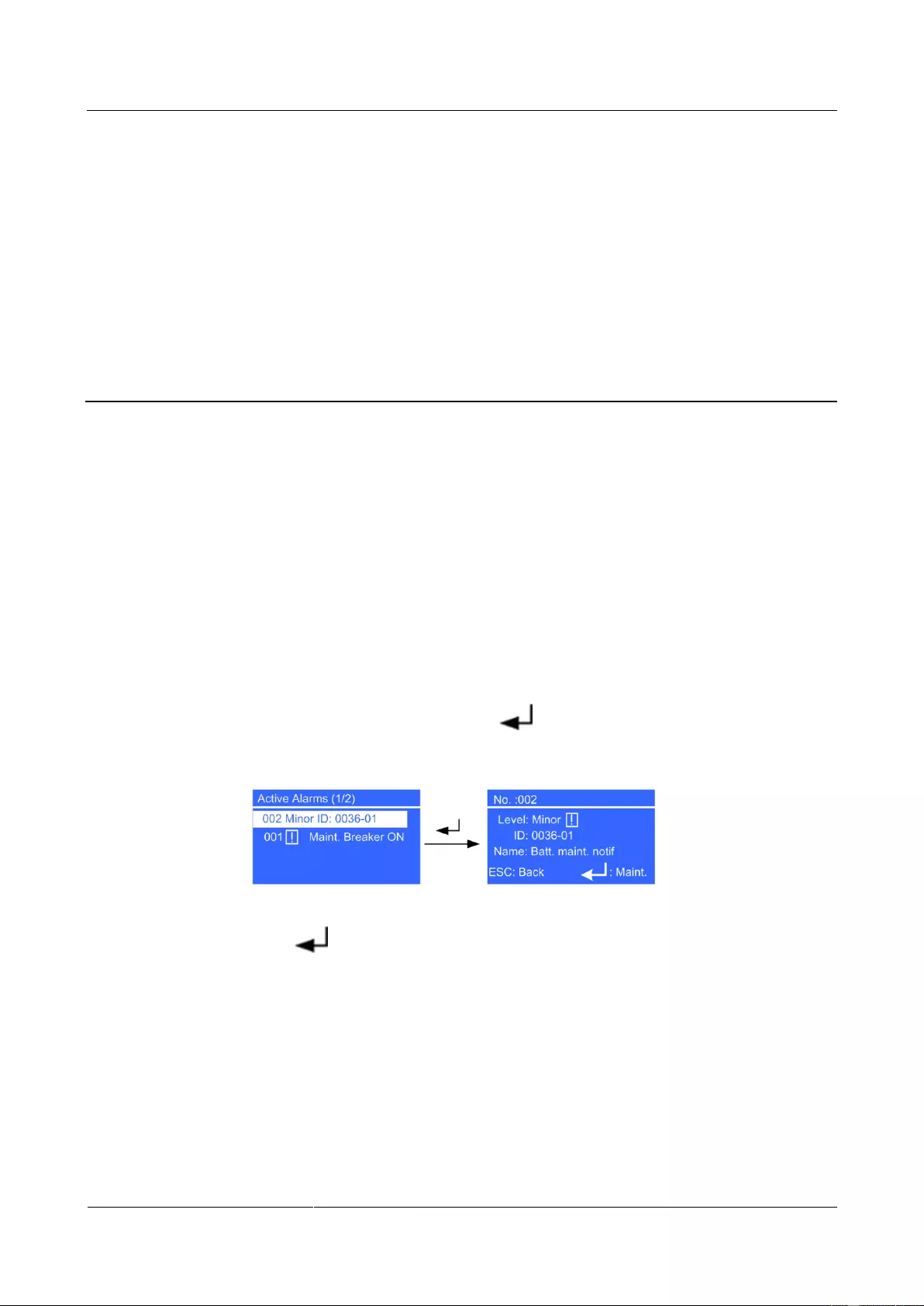
UPS2000-G-(6 kVA-20 kVA)
User Manual
D Alarm Handing of Battery Maintenance Notification
Copyright © Huawei Technologies Co., Ltd.
D Alarm Handing of Battery Maintenance
Notification
Context
If no battery shallow discharge test is performed within 60 days after a UPS2000-G is
installed and the maintenance notification time has arrived, the mains indicator is on, the
battery and bypass indicators are off, the fault indicator on the info key are blinking red, and
alarms are generated intermittently.
Procedure
Step 1 Clear the Batt. maint. notif alarm.
1. Press the i key on the UPS control panel to display the Active Alarms page. If multiple
active alarms exist, use the ▲ or ▼ key to select the alarm record on the top (the latest
alarm is on the top by default). Press to view the alarm ID and name.
Figure D—1 Viewing alarms
2. Press to display the Maintain Batteries screen. Then the Batt. maint. notif alarm
disappears and timing for the next notification starts, regardless of whether you perform
a discharge test. The battery maintenance notification 0036-01 in the active alarm menu
will disappear.
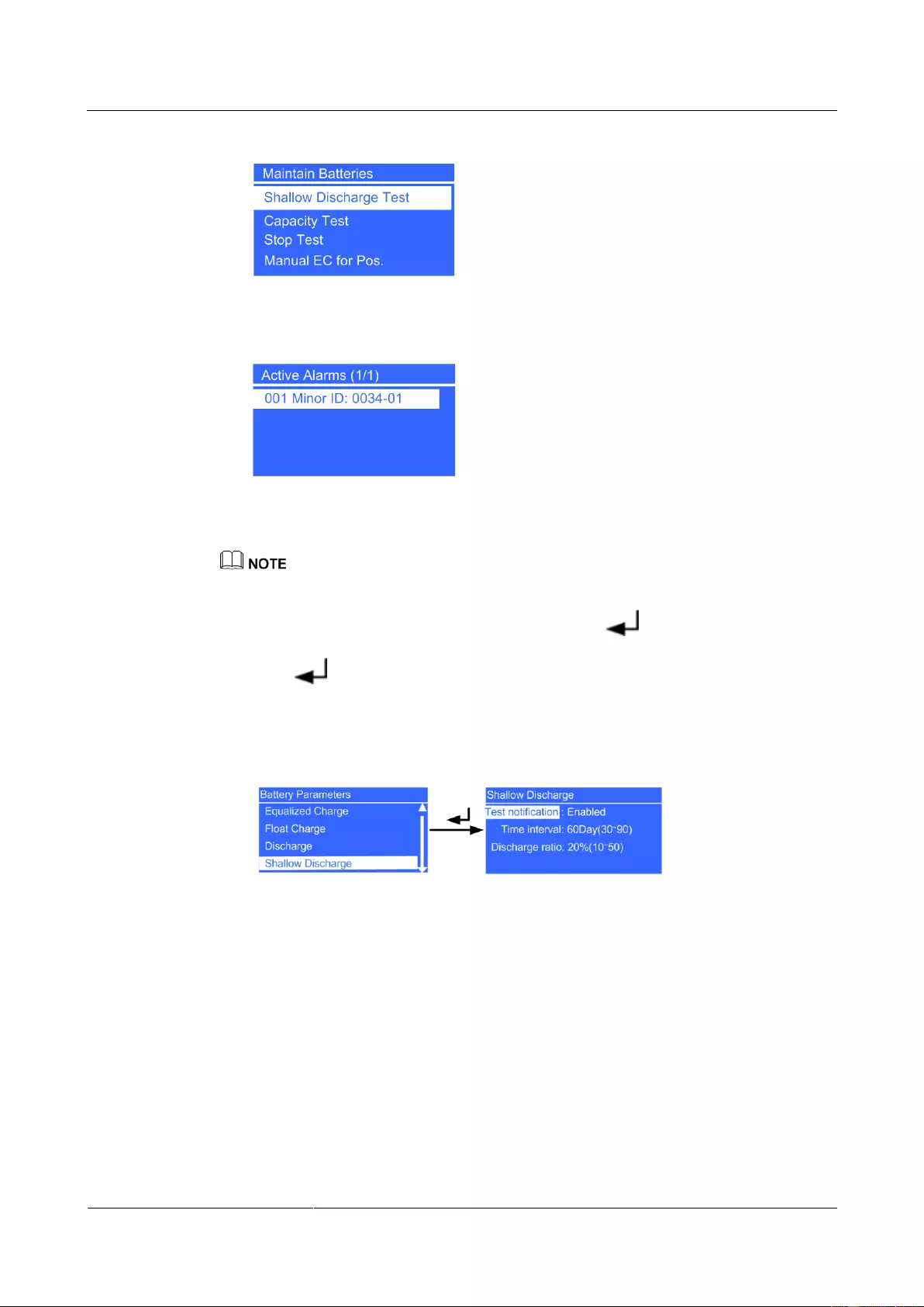
UPS2000-G-(6 kVA-20 kVA)
User Manual
D Alarm Handing of Battery Maintenance Notification
Copyright © Huawei Technologies Co., Ltd.
Figure D—2 Maintain Batteries screen
Figure D—3 Active Alarms screen
Step 2 Cancel the battery maintenance notification function.
If you do not want the battery maintenance notification 0036-01 to appear again, perform the following
steps:
1. On the Main Menu screen, select Settings and press . The Settings login screen is
displayed. The preset password is 000001. After you enter the correct password and
press , the Settings screen is displayed.
2. Choose Battery Parameters and Shallow Discharge, and then change the value of Test
notification from Enable to Disable (configurable when the UPS works in any mode).
Figure D—4 Shallow Discharge screen
—-End
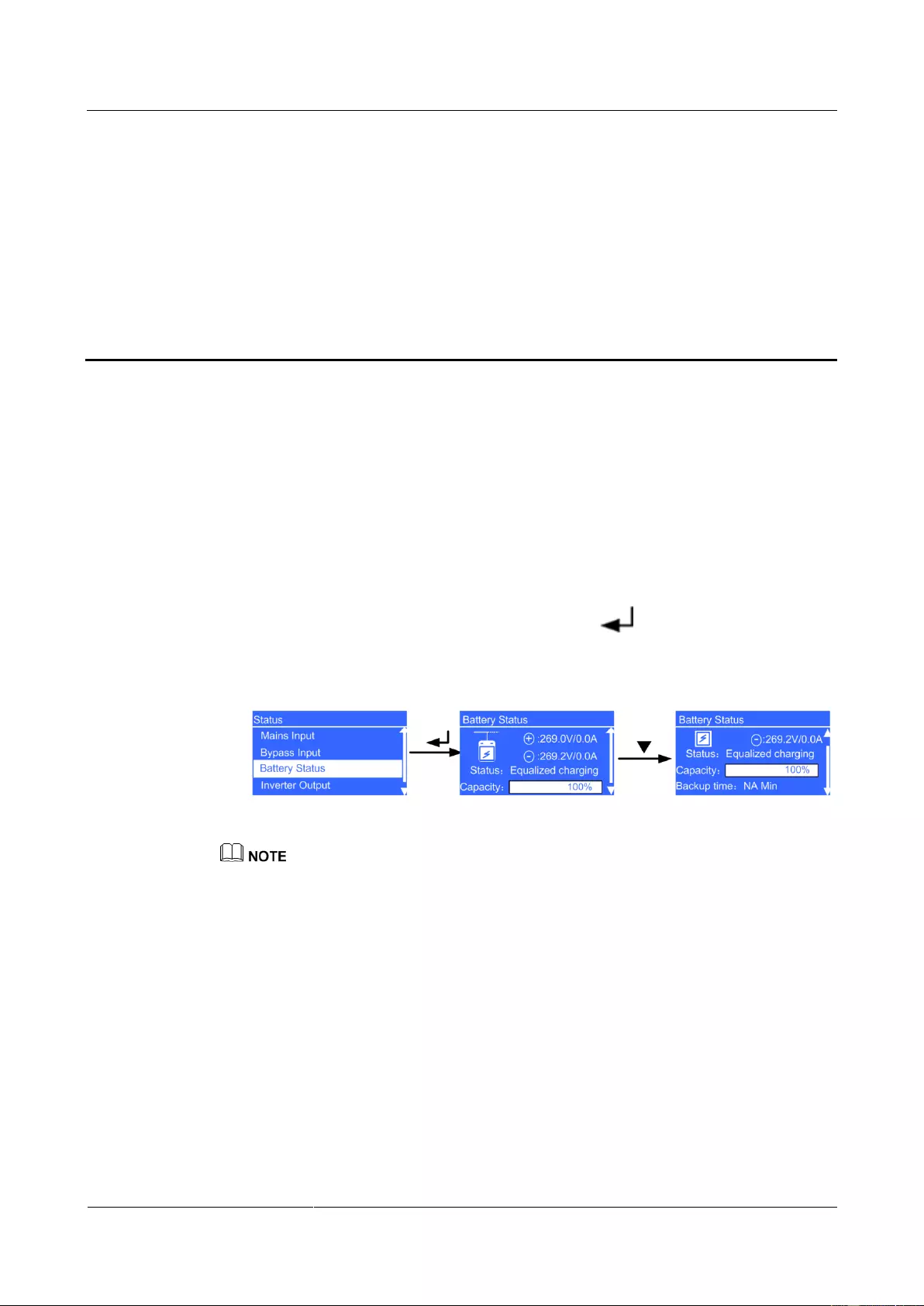
UPS2000-G-(6 kVA-20 kVA)
User Manual
E Battery Shallow Discharge Test
Copyright © Huawei Technologies Co., Ltd.
E Battery Shallow Discharge Test
Context
A shallow discharge test method that tests the battery loop reliability and short-time backup
capacity after batteries are charged for a long time (60 days by default, 30 days to 90 days
configurable).
Procedure
Step 1 Check the battery status for test start conditions.
1. On the Main Menu screen, choose Status and click . On the Status screen, locate
Battery Status.
Figure E—1 Battery Status menu
Status: The battery status is NA (battery not connected or reversely connected), Equalized
charging, Float charging, Hibernating, or Discharging.
Capacity: indicates the remaining battery capacity.
Backup time: indicates the estimated discharge duration. The value is NA during battery charging.
2. Batteries in Hibernating state cannot start a shallow discharge test. Choose Control and
Maintain Batteries, and then click Manual Float Charging to switch the batteries to
the float charging state. If the batteries hibernate due to a charger alarm, the batteries can
switch between float charging and equalized charging only after the alarm is cleared.

UPS2000-G-(6 kVA-20 kVA)
User Manual
E Battery Shallow Discharge Test
Copyright © Huawei Technologies Co., Ltd.
Figure E—2 Manual FC for Pos. screen
For the 6 kVA and 10 kVA UPSs, perform manual float charging, for the 15 kVA and 20 kVA UPSs,
batteries in positive and negative groups are manually switched to float charging respectively.
Step 2 Adjust the discharge ratio for the shallow discharge test.
1. On the Main Menu screen, select Settings and press . The Settings login screen is
displayed. The preset password is 000001. After you enter the correct password and
press , the Settings screen is displayed.
2. Choose Battery Parameters and Shallow Discharge, and adjust the parameters to fit
actual requirements.
Figure E—3 Shallow Discharge screen
Discharge ratio: indicates the percentage of discharge capacity to the total dischargeable
capacity. The parameter can be set to a value between 10% and 50%, and the default
value is 20%. The parameter is configurable in any mode. It is recommended that the
value of Discharge ratio not exceed 20% with the load is light. For example, the value
can be 10% or 15%.
Step 3 Start the shallow discharge test: Partially discharge the batteries. After all required conditions
are met, the test command is successfully delivered and the LCD displays a Succeeded
message.
Figure E—4 Shallow Discharge screen
If the shallow discharge test command is successfully executed, the charger disables its output
and the system is in battery mode. You can view the battery information on the default screen
(energy flow diagram). The normal mode indicator (green) turns off, and the battery mode
indicator (yellow) turns on.
Step 4 Stop the shallow discharge test forcibly.
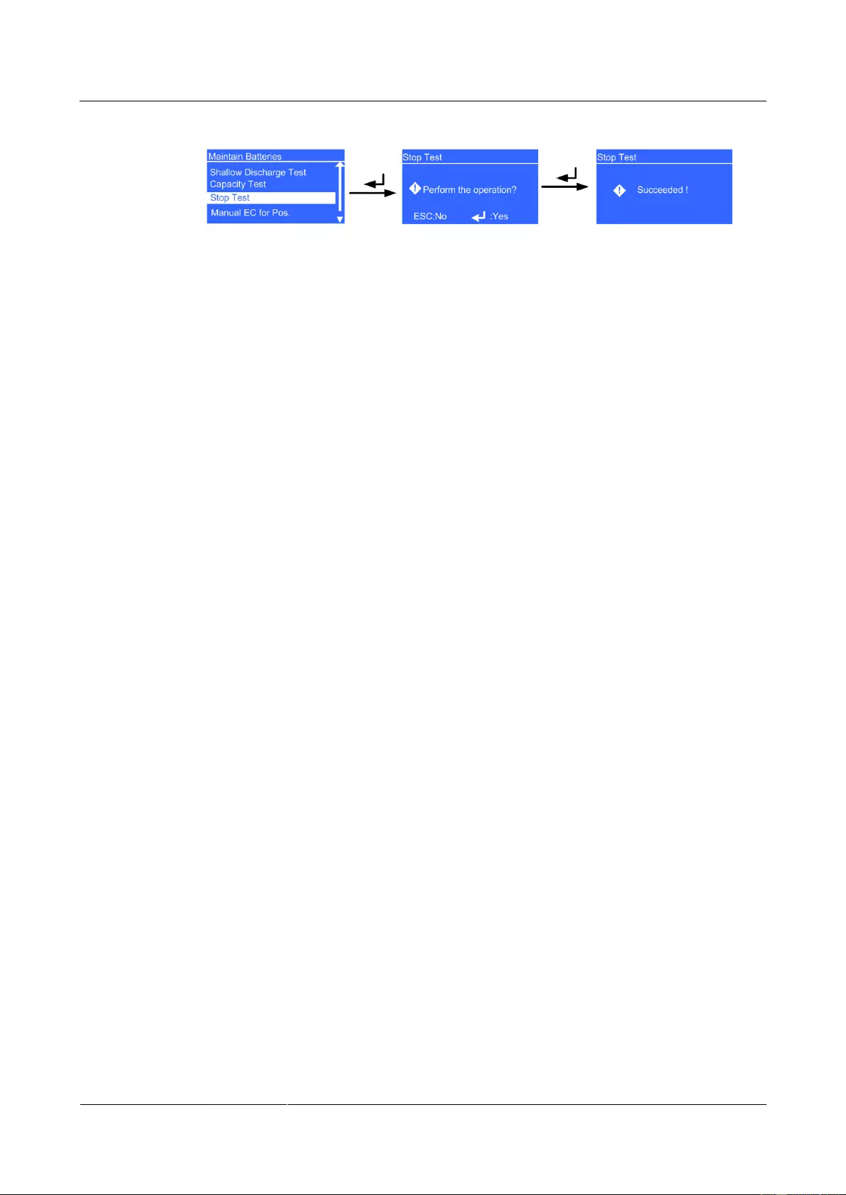
UPS2000-G-(6 kVA-20 kVA)
User Manual
E Battery Shallow Discharge Test
Copyright © Huawei Technologies Co., Ltd.
Figure E—5 Stop Test screen
—-End
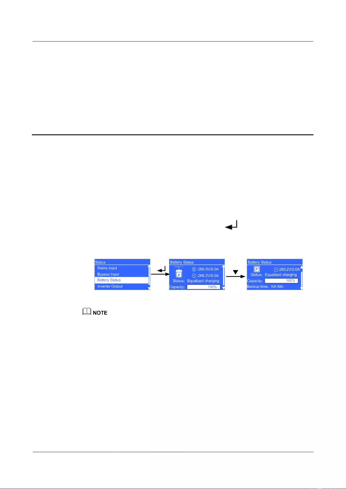
UPS2000-G-(6 kVA-20 kVA)
User Manual
Copyright © Huawei Technologies Co., Ltd.
F Capacity Test
Context
A deep discharge test method that tests the battery real-time capability and long-time backup
capability after batteries have not experienced deep discharging for a long time.
Procedure
Step 1 Check the battery status for test start conditions.
1. On the Main Menu screen, choose Status and click . On the Status screen, locate
Battery Status.
Figure F—1 Battery Status menu
Status: The battery status is NA (battery not connected or reversely connected), Equalized
charging, Float charging, Hibernating, or Discharging.
Capacity: indicates the remaining battery capacity.
Backup time: indicates the estimated discharge duration. The value is NA during battery charging.
2. Batteries in Hibernating state cannot start a capacity test. Choose Control and
Maintain Batteries, and then click Manual Float Charging to switch the batteries to
the float charging state. Charge the batteries until the battery capacity reaches 100%. If
the batteries hibernate due to a charger alarm, the batteries can switch between float
charging and equalized charging only after the alarm is cleared.
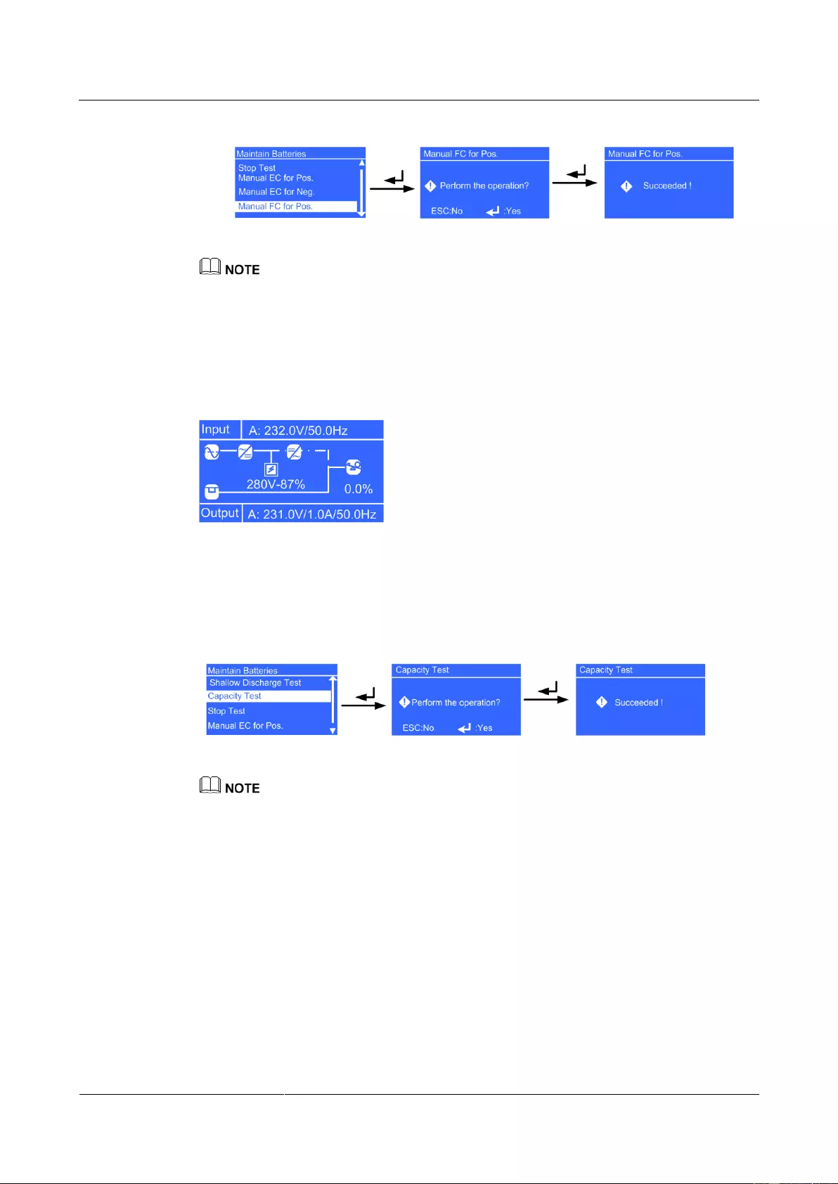
UPS2000-G-(6 kVA-20 kVA)
User Manual
Copyright © Huawei Technologies Co., Ltd.
Figure F—2 Manual FC for Pos. screen
For the 6 kVA and 10 kVA UPSs, perform manual float charging, for the 15 kVA and 20 kVA UPSs,
batteries in positive and negative groups are manually switched to float charging respectively.
Step 2 Adjust the load rate of the local UPS to a value between 20% and 80%. The actual load rate
can be viewed in t he energy flow diagram. If the actual load rate is below 20%, you ca nnot
perform a test. If so, add some IT equipment to increase the load to above the lower limit.
Figure F—3 Viewing the load rate
Step 3 Start the capacity Test: Partially discharge the batteries and ensure that the load rate is
between 20% and 80%. After all required conditions are met, the test command is
successfully delivered and the LCD displays a Succeeded message.
Figure F—4 Shallow Discharge screen
If the load rate and battery capacity do not meet the requirements, the system displays a message
indicating load not met and Batt. not fully charged. In this case, you need to reset the load rate and
battery capacity.
If the capacity Test command is successfully executed, the charger disables its output and the
system is in battery mode. You can view the battery information on the default screen (energy
flow diagram). The normal mode indicator (green) turns off, and the battery mode indicator
(yellow) turns on.
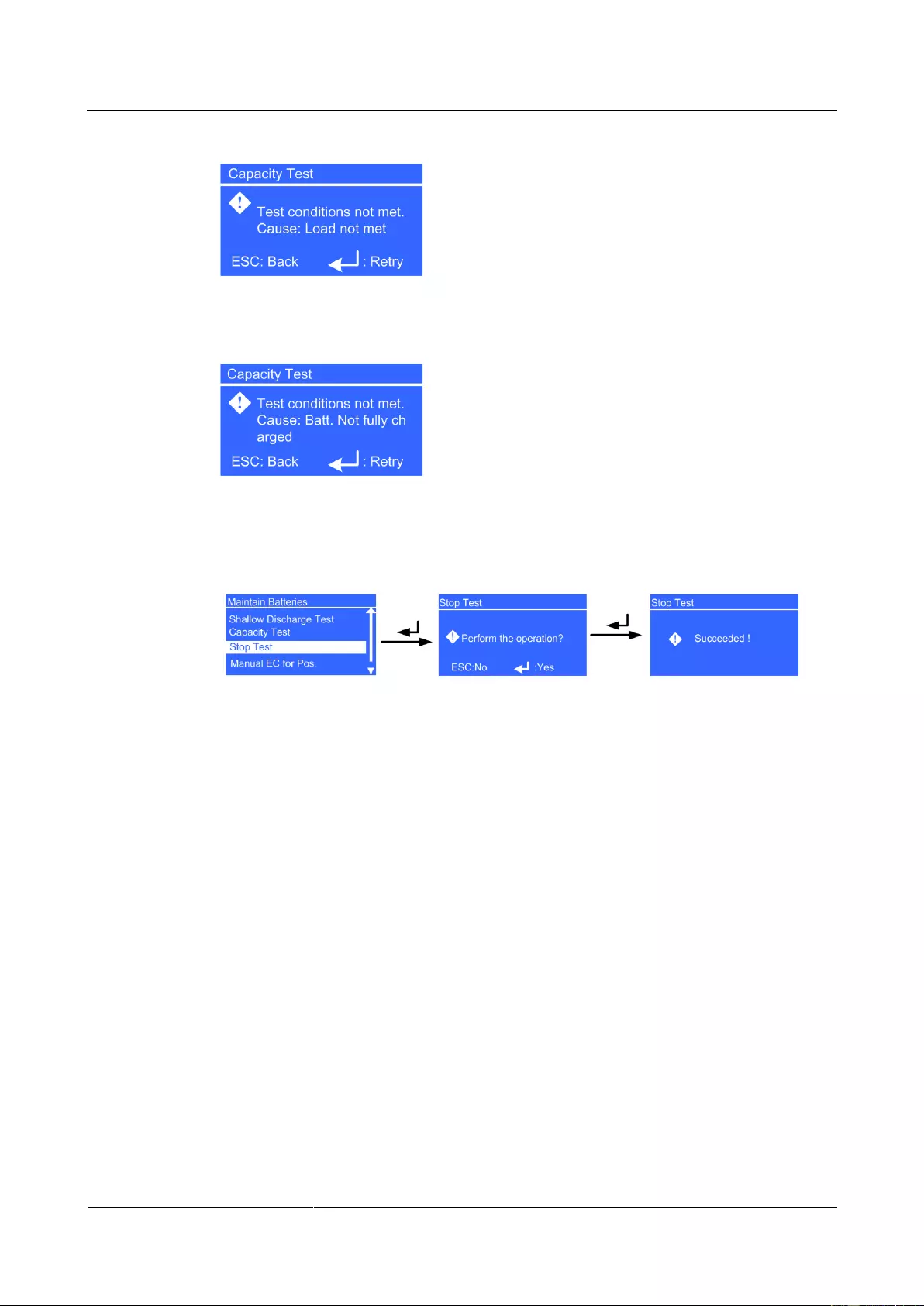
UPS2000-G-(6 kVA-20 kVA)
User Manual
Copyright © Huawei Technologies Co., Ltd.
Figure F—5 Load not met
Figure F—6 Batt. not fully charged
Step 4 Stop the capacity Test forcibly.
Figure F—7 Stop Test screen
—-End

UPS2000-G-(6 kVA-20 kVA)
User Manual
G Acronyms and Abbreviations
Copyright © Huawei Technologies Co., Ltd.
G Acronyms and Abbreviations
application-specific integrated circuit
complex programmable logical device
digital signal processing
economy control operation
Hypertext Transfer Protocol Secure
management information base
network management system

UPS2000-G-(6 kVA-20 kVA)
User Manual
G Acronyms and Abbreviations
Copyright © Huawei Technologies Co., Ltd.
Simple Network Management Protocol
total harmonic distortion of output voltage
telecommunication network voltage
uninterruptible power system
valve regulated lead acid
Huawei UPS,UPS2000G,10kVA,Single phase/Three phase input single phase output,Tower or Rack,Long,0h,220/230/240VAC,50/60Hz (UPS2000-G-10KRTL)
245 584.15 руб.*
3 026.78 у.е.
с НДС 20%
* — Розничная цена
Проектная цена: 221 025.74 руб
(2 724.10 $), условия получения.
Рейтинг 5/5
1
Код товара: 405272
Артикул: 02290251.
Доставка
при оплате сегодня (21.04.2025):
Москва:
— Самовывоз:
от 3-х дней
— Курьером:
от 3-х дней
Регионы РФ:
— Курьером:
от 3-х дней
— ТК:
от 3-х дней
Работа с юридическими лицами
наше приоритетное направление
Подробнее
Способы оплаты
— Безналичный расчёт
— Оптовые скидки
— Рассрочка и кредит
- Описание
- Характеристики
- Документы
- Обзоры
ИБП Huawei UPS2000G 10kVA UPS2000-G-10KRTL 02290251. — описание
Ибп Huawei UPS,UPS2000G,10kVA,Single phase/Three phase input single phase output,Tower or Rack,Long,0h,220/230/240VAC,50/60Hz (UPS2000-G-10KRTL)
Все характеристики
ИБП Huawei UPS2000G 10kVA UPS2000-G-10KRTL 02290251. — технические характеристики
| Аварийное отключение питания (EPO) | Да |
|---|---|
| Байпас | Встроенный байпас |
| Диапазон входного напряжения при работе от сети, В | 80-380 |
| Диапазон регулировки выходного напряжения (В) | Возможно конфигурирование для работы с выходным напряжением номиналом 220 : 230 или 240 В |
| Интерфейсный порт | USB |
| Максимальная выходная мощность, Вт/ВА | 9000/10000 |
| Панель управления | Многофункциональная консоль контроля и управления с ЖК-дисплеем |
| Тип ИБП | Двойное преобразование |
| Тип установки | В стойку/напольный |
| Тип формы напряжения | Синусоидальный сигнал |
| Номинальное выходное напряжение, В | 230 |
| Номинальное входное напряжение, В | 220/230/240 |
| Тип входного соединения | Hard Wire 3 wire (L+N+PE); Hard Wire 5-wire (3Ph+N+PE) |
| Вес, кг | 16.0000 |
| Цвет | Черный |
| Звуковой сигнал | Да |
В каталоге нашего сайта Вы можете получить «ИБП Huawei UPS2000G 10kVA UPS2000-G-10KRTL 02290251.» по небольшой цене. На этой странице можно ознакомиться с параметрами этого товара. Цена включает НДС. Для получения дополнительных сведений обращайтесь к нашим менеджерам по номеру телефона 8 800 100-76-17. Если вы уже выбрали подходящий товар, оформите заказ через корзину или по почте, и наши менеджеры в течение часа свяжутся для его подтверждения. Если Вы ещё не определились с моделью, то сможете получить консультацию от специалиста. «ИБП Huawei UPS2000G 10kVA UPS2000-G-10KRTL 02290251.» отличается высоким надёжностью. Все товарные позиции на нашем сайте можно оплатить различными способами. Мы предоставляем отличные скидки на оптовые заказы. На все товары распространяется официальная гарантия от производителя. Если вы не нашли на сайте требуемый продукт, то его наличие можно уточнить. Мы находимся в Москве и доставляем заказы по всей территории России. В Москве возможно получить товар из точки самовывоза или заказать быструю доставку курьером. По Российской Федерации мы доставляем товары транспортными компаниями. Мы предоставляем полный набор сопроводительных документов для клиента.
- Оставьте отзыв
- Задать вопрос
Дизайн
Функционал
Качество
Цена
Похожие
товары
Работаем с любыми способами оплаты: принимаем наличные, предоплату и предоставляем кредит. Наш товар доставляется в любую точку России. Мы работаем с крупнейшими перевозчиками, которые доставят Ваш заказ быстро и надежно. Доставка по Москве зависит от стоимости и весогабаритов заказа. Возможна бесплатная доставка, условия обсуждаются с менеджером. Все цены указаны в рублях и включают НДС 20% (кроме лицензий на ПО). Работаем как с бумажными документами, так и с электронными через ЭДО.
Вы можете самостоятельно произвести оплату на сайте. После оформления заказа и одобрения его менеджером Вам будут предложены следующие варианты оплаты:
1. Банковской картой (Visa, MasterCard, Maestro, МИР).
2. Банковским переводом для юридических и физических лиц по выставленному счету.
3. Электронными деньгами через платёжный сервис Яндекс Касса.
4. По частям через платёжный сервис Яндекс Касса.
Краткое описание UPS2000-G-10KRTL
UPS,UPS2000G,10kVA,Single phase/Three phase input single phase output,Tower or Rack,Long,0h,220/230/240VAC,50/60Hz
Мы предлагаем следующие способы доставки товара:
Самовывоз из пункта выдачи
Самостоятельное получение заказа в пункте выдачи. Дата и время получения заранее согласуется с менеджером магазина.
Отгрузка товара юридическим лицам осуществляется только при наличии печати или правильно оформленной и заполненной доверенности, наличии паспорта получателя.
Курьерская доставка по Москве
Доставка по адресу покупателя или до пункта приема транспортной компании в г. Москве. Дата и время доставки заранее согласуется с менеджером магазина.
Доставка транспортной компанией по России
Доставка транспортной компанией по России до пункта выдачи транспортной компании или до конечного адреса покупателя.
Мы предлагаем следующие способы оплаты товара:
Оплата наличными
Оплата за наличный расчет для физических и юридических лиц. После внесения денежных средств Покупатель подписывает товаросопроводительные документы и получает кассовый чек.
Безналичная оплата
Мы работаем с физическими и юридическими лицами за безналичный расчёт со 100% предоплатой с оформлением всех предусмотренных законодательством документов. Счёт на оплату направляется Покупателю на электронную почту после запроса счета через форму на сайте либо по электронной почте. Цена на заказанный товар действительна в течение 2 дней с момента оформления Заказа.
Электронные способы
Оплата Заказа электронными способами, в т.ч. банковскими картами. Оплата Заказа данным способом доступна запросом ссылки на оплату у нашего менеджера.
Если у вас возникнут вопросы по оформлению заказа, вы можете обратиться к нам, позвонив по телефону +7 495 120-65-21 или связавшись по электронной почте sale@ru-huawei.com. Мы гарантируем оперативный ответ на ваш запрос и предоставление наилучших условий от официального поставщика HUAWEI.
Запрос цены или КП
Мы предоставляем официальную гарантию на всю продукцию.
Сервис расширенной гарантии включает в себя:
- Приемку в сервисном центра для выполнения диагностики дефекта.
- Ремонт.
- Бесплатную доставку клиенту.
В рамках дополнительной программы оборудование HUAWEI может быть поставлено с расширенной гарантией HUAWEI. Cрок расширенной гарантии HUAWEI – 12 месяцев с даты регистрации партнером продажи данного оборудования в базе данных компании HUAWEI. По желанию клиента расширенная гарантия может быть продлена на следующие 12 месяцев по истечению первоначального срока или приобретена сразу на 24 или 36 месяцев.
Контакты гарантийного отдела:
Телефон: +7 495 120-65-21
E-mail: sale@ru-huawei.com
Получить КП / Счет
Для расчета коммерческого предложения или получения счета на поставку оборудования HUAWEI оставьте заявку в форме ниже или свяжитесь с отделом продаж по телефону +7 495 120-65-21 или электронной почте sale@ru-huawei.com. Мы гарантируем оперативный ответ на ваш запрос и предоставление наилучших условий от официального поставщика HUAWEI.
Специалист по решениям HUAWEI:
- Окажет профессиональную консультацию.
- Сообщит вашу цену на продукцию.
- Сообщит информацию об актуальных акциях и скидках.
- Подскажет ближайшее к вам отделение с наличием нужной продукции.
- Согласует с вами возможную дату и время доставки.
Запрос цены или КП
UPS2000-H-(6 kVA–10 kVA) Quick Guide
Issue: 02
Date: 2021-10-13
Installation Preparations
NOTICE
- Before installing the devices, read the user manual carefully to get familiar with product information and safety precautions.
- Use insulated tools during installation.
- Only engineers certified by Huawei or its agents are allowed to install, commission, and maintain the UPS. Otherwise, personal injury or equipment damage may occur, and the UPS faults caused are beyond the warranty scope of Huawei.
- When routing power cables and communications cables, prevent cables from being scratched by cabinet components.
| Model | Weight | Dimensions (H x W x D) |
| UPS2000-H-6KRTL-Li | 14 kg | 43 mm r 430 mm x 514 mm |
| UP52000-H-10KRTILI | 17 kg | 86 mm x 430 mm x 514 mm |
| Model | Wiring Terminal | Number of Phases | Rated Voltage | External Circuit Breaker | Cable Cross-sectional Area | Terminal Type | Note | |
| 6 kVA:single-phase input single-phase output) | AC input | L/N/PE | 1 | 220 V AC/230 V AC/240 V AC | 50 A (feature C) | 10 mm’ | OT-10 mm’-M6 terminal | M4 screw tightening torque: 1.2 Nei Torque for tightening screws: 4.8 Nm Notes •Use flexible conductors with a working temperature of 90 *C or softer conductors for power cables. Cables with solid conductors or twisted conductors may fail to be Installed. •II there is no battery bus bar (BBB) box, connect battery cables to the UPS. Select 01 terminals based on the battery cables. •a: The lithium battery Is equipped with a circuit breaker. •b: In bypass mode, the UPS obtains power from phase A. The input current Is the three-phase total current |
| AC output | L/N/PE | 1 | 40 A (feature D) | 6 mm’ | OT-6 m&-M6 terminal | |||
| Battery | + | 2 | 54 V DC | 160 A• | 2 x 25 Imre | OT 25 mm’-M6 terminal | ||
| — | 2 x 25 mats | |||||||
| PE | — | 2 x 6 mm’ | OT-6 mm,-90′ bending-AM terminal | |||||
| 10 kVA (single-phase input single-phase output) | AC input | L/N/PE | 1 | 220 V AC/230 V AC/240 V AC | 80 A (feature C) | 16 mm2 | OT-16 mm’-M6 terminal | |
| AC output | L/N/PE | 1 | 63 A (feature 0) | 16 mm | OT-16 mm terminal | |||
| Battery | + | 2 | 54 V DC | 250 • | 2 x 35 mm’ | 01-35 mm’-M6 terminal | ||
| — | 2 x 35 mm’ | |||||||
| PE | — | 2 x6 mm’ | 01•6 mm’-M6 terminal | |||||
| 10 kVA (three-phase input single-phase output) | AC input | 1./N/PE | 3 | 380 V AC/400 V AC/415 V AC | 80 A° (feature C) | 16 MO | OT•16 mm’-M6 terminal | |
| AC output | L/N/PE | 1 | re 63 A (feature 0) |
16 M O | OT•16 mm’•M6 terminal | |||
| Battery | + | 2 | 54 V DC | 250 A• | 2 x 35 mm’ | OT•35 mm’-M6 terminal | ||
| — | 2 x 35 mm’ | |||||||
| PE | + | 2 x 6 mm’ | OT-6 mm’-M6 terminal | |||||
| lithium battery | + | 2 | 54 V DC | — | 25 m2 | OT 25 mm’-M6 terminal | ||
| — | 25 mm | |||||||
| PE | 6 mm’ | OT-6 mm’-M6 terminal |

Installing a UPS

NOTE
- The installation of the 6 kVA UPS is similar to that of the 10 kVA UPS. This document uses the 6 kVA UPS as an example. Perform operations based on the actual situation.
- A UPS supports a maximum of eight lithium batteries in parallel.
- It is recommended that the BBB box be installed behind the lithium batteries.
- If four groups of batteries are installed in the rack-mounted mode, reserve 1 U space between every two groups of lithium batteries battery cables.
- You are advised to reserve 1 U space between UPSs, 1 U space between the UPS and lithium battery, and 1 U space above the UPS.
Typical Tower-mounted Scenario
NOTE
- The following uses one 6 kVA UPS and four lithium batteries in tower-mounted mode with a junction box as an example.
- A subrack can house a maximum of three devices and only one UPS is supported.
- In a single-server scenario, if more than six lithium batteries are installed, two junction boxes need to be installed.

Installing Cables
Installing AC Power Cables (Single UPS)
- Connect UPS AC input and output power cables in the same phase sequence. Connect battery terminals correctly.
- Before connecting cables to the UPS, ensure that the input circuit breaker and output circuit breaker are OFF to prevent operations with power on.
- If the input or output cables has to be changed, contact Huawei technical support if you are not familiar with the operation. Do not power on the UPS directly.
- If the input or output system is changed, ensure that the short-circuit copper bar status and cable connections at input and output ports are correct.
- In a single UPS system, connect loads to AC OUTPUT sL and pL terminals. Connect primary loads to the sL terminal and secondary loads to the pL terminal.
6. K1: UPS input circuit breaker; Q1: UPS output circuit breaker.

Installing Battery Cables (Single UPS)
NOTE
When replacing a faulty lithium battery, disconnect all loops between the UPS and the battery to prevent maintenance with power on.

Installing AC Power Cables (Parallel System)
- Ensure that the AC input and output power cables on each UPS are connected in the same phase sequence, battery terminals are connected correctly, and the bypass power cables are connected in the same phase sequence.
- Before cable connection, turn off all circuit breakers in the parallel system.
NOTICE
- The UPS can generate large leakage currents. A circuit breaker equipped with a residual current device (RCD) is not recommended. If leakage protection is required, select a recommended circuit breaker.
- Circuit breakers used for cable connection need to be provided by the customer.
- When UPSs are connected in parallel, the output parallel power cables of each UPS must be at least 1 m long and the length deviation must be less than ±10%. The four cables must be connected at the remote end.
- K: general AC input circuit breaker; K1: UPS 1 input circuit breaker; K2: UPS 2 input circuit breaker; Q: general AC output circuit breaker; Q1: UPS 1 output circuit breaker; Q2: UPS 2 output circuit breaker; B1–Bn: lithium battery circuit breakers.
| Installing Communications Cables (Parallel System) |
Verifying the Installation
| No. | Check Item |
| 1 | If the input or output system is changed, ensure that the short-circuit copper bar status and cable connections at input and output ports are correct. |
| 2 | The phase sequence of the input power is correct. Use a multimeter to check that the input and output are not short-circuited. |
| 3 | Cables and terminals are securely connected. |
| 4 | Battery cables and terminals are connected correctly, and voltages comply with industry standards. |
| 5 | The UPS is properly connected to the lithium battery string. |
| 6 | Input circuit breakers and load circuit breakers are OFF. |
| Power cables and signal cables are correctly identified. | |
| 8 | The ground cable is reliably connected. The voltage difference between the neutral wire and the ground cable is less than 5 V AC. |
| 9 | The build-out resistor is correctly installed. |
| 10 | The voltage range of the UPS upstream input circuit breaker is 80-280 V AC (phase voltage), and the rated frequency is 50 Hz/60 Hz. |
| 11 | The positive and negative voltages of the lithium battery measured by a multimeter range from 41 V to 51 V. |
Startup
NOTICE
- Before powering on the UPS, ensure that the UPS has passed all check items in «Verifying the Installation.»
- The voltage range of the UPS upstream input circuit breaker is 80–280 V AC (phase voltage), and the rated frequency is 50 Hz/60 Hz.
| Power Button Function | Description |
| Starting the inverter | When the UPS works in bypass mode (the bypass indicator is on), hold down the button on the UPS panel for more than 5s. Release the button when the inverter indicator blinks and you hear a beep sound. Do not press any button during inverter startup. When the startup command is successfully delivered, and the inverter indicator is steady on, the UPS enters normal mode. |
| Shutting down the inverter | When the UPS works in inverter mode, hold down the button on the UPS panel for more than 5s. Release the button when the inverter indicator blinks and you hear a beep sound. Do not press any button during the inverter shutdown. When the shutdown command is successfully delivered, and the inverter indicator is off, the UPS shuts down the inverter output and enters bypass mode. |
| Enabling WiFi | When the WiFi is disabled, press and hold the button for 0.5s to enable the WIFi (the WiFi indicator is on). |
| Disabling WIFi | When the WiFi is enabled, press and hold the button for 0.5s to disable the WIFi (the WiFi indicator Is off). |
| Cold-Starting the UPSs Using Batteries | When the mains is abnormal or disconnected, connect the battery and hold down the lithium battery switch for at least 5s and less than 15s to power on the lithium battery. Hold down the UPS button for 3s (the bypass indicator, battery indicator, and Inverter indicator are on at the same time), and the UPS Is powered on. After the UPS Initialization Is complete (about 10s), the indicator status changes and the UPS enters the standby state (the WiFi Indicator Is on and the fault Indicator blinks). Hold down the UPS button for more than Ss, and the UPS enters battery mode. |
Starting a UPS
- Hold down the MANUAL ON/OFF button on the lithium battery panel for at least 5s and less than 15s to power on the lithium battery.
- Switch on the mains AC input circuit breaker K1 for the UPS. The UPS works in bypass mode (the bypass indicator is on). The sL terminal outputs bypass voltage and the pL terminal has no voltage output.
- If the alarm indicator on the UPS panel is blinking, view the alarm details on the app and handle the alarm.
- Perform «startup operations» on the UPS by using one of the following methods for the UPS to work in normal mode:
• When the UPS works in bypass mode (the bypass indicator is on), hold down the button on the UPS panel for more than 5s. Release the button when the inverter indicator blinks and you hear a beep sound. Do not press any button during inverter startup. When the startup command is successfully delivered, and the inverter indicator is steady on, the UPS enters normal mode.
• Choose Configuration > Control > Power-on/off on the app to start the inverter. After a successful startup, the UPS enters normal mode.
For details about how to install and log in to the app, see the Appendix.
• On the WebUI, choose Monitoring > UPS System > Running Control to start the UPS. - When the UPS runs properly, switch on the UPS AC output circuit breaker Q1 to supply power to loads.
Starting a Parallel System
- Hold down the MANUAL ON/OFF button on the lithium battery panel for at least 5s and less than 15s to power on the lithium battery.
- Switch on the UPS mains input circuit breakers K1 and K2, the general mains input circuit breaker K, and the UPS AC output circuit breakers Q1 and Q2. The parallel system has no output.
- If the alarm indicator on the UPS panel is blinking, view the alarm details on the app and handle the alarm. For details about how to install and log in to the app, see the Appendix.
- The parallel configuration parameters are adaptive. Choose Config > System Parameters > Parallel system. You can manually set the parameters as required.
- Start the UPS one by one and shut down the inverters. The output PL terminal has voltage output.
- Switch on output circuit breaker Q1 (provided by the customer), switch off output circuit breaker Q2 (provided by the customer), and check that the voltage difference between the two ends of output circuit breaker Q2 does not exceed 2 V.
- Switch on the output circuit breaker Q2.
- After you perform «startup operations» on each UPS in the parallel system, all UPSs transfer to normal mode.
- When the parallel system runs properly, switch on the general output circuit breaker Q (provided by the customer) and branch output circuit breakers (provided by the customer), and start loads one by one.
Shutting Down a Parallel System
Shutting Down a Single UPS in the Parallel System
- Perform «shutdown operations» twice within 30s for a UPS in the parallel system. Then the UPS shuts down and generates no output. Other UPS works without being affected.
- Hold down the MANUAL ON/OFF button on the lithium battery panel for at least 5s and less than 15s to power off the lithium battery.
- Switch off the AC input circuit breakers K1 and K2 and AC output circuit breakers Q1 and Q2 for the UPS. After all indicators turn off and fans stop, the UPS shuts down.
- The UPS exits from the parallel system.
Transferring a Parallel System to Bypass Mode
Perform «shutdown operations» on each UPS in the parallel system. All UPSs shut down the inverters and transfer to bypass mode.
Powering Off a Parallel System
- Shut downloads.
- Perform «shutdown operations» on each UPS in the parallel system. All UPSs shut down the inverters and transfer to bypass mode.
- Hold down the MANUAL ON/OFF button on the lithium battery panel for at least 5s and less than 15s to power off the lithium battery.
- Switch off the mains AC input circuit breakers K1 and K2 and the general mains AC input circuit breaker K for the UPS system.
Switch off the UPS AC output circuit breakers Q1 and Q2 and the general AC output circuit breaker Q for the UPS system. After all indicators turn off and fans stop, the UPSs shut down, and the loads power off.
Appendix
Installing the App
- Use a mobile device to scan the QR code on the UPS panel.

- Install the app using either of the following methods:
•Download the NetEco app using a browser and install it.
•Download the NetEco app from Huawei AppGallery and install it.

Shutdown
Shutting Down a Single UPS
Shutting Down the Inverter to Transfer the UPS to Bypass Mode
Perform «shutdown operations» on the UPS by using one of the following methods:
- When the UPS works in inverter mode, hold down the button on the UPS panel for more than 5s. Release the button when the inverter indicator blinks and you hear a beep sound. Do not press any button during the inverter shutdown. When the shutdown command is successfully delivered, and the inverter indicator is off, the UPS shuts down the inverter output and enters bypass mode.
- Choose Configuration > Control > Power-on/off on the app to shut down the inverter. After a successful shutdown, the UPS enters the bypass mode.
Powering Off a Single UPS
- Shut down loads.
- Perform «shutdown operations» on the UPS. The inverter shuts down, and the UPS transfers to bypass mode.
- Hold down the MANUAL ON/OFF button on the lithium battery panel for at least 5s and less than 15s to power off the lithium battery.
- Switch off the mains AC input circuit breaker K1 and output circuit breaker Q1 of the UPS. After all indicators turn off and fans stop, the UPS shuts down, and the loads power off.
Logging In to the App
NOTE
- After the initial login, change the password in time to improve account security and prevent data tampering.
- For the first login, you need to enter the WiFi password.
- Enable WLAN on your phone.
- Turn off mobile data on your phone.
- Power on the UPS.
- Press and hold the UPS button for about 0.5s to enable the UPS WiFi (the WiFi indicator is steady on).
- Open the NetEco app on a mobile device. The Select Application screen is displayed.
- Tap UPS. The Connect WiFi screen is displayed. Use either of the following methods to connect to the WiFi network.
•Manually connect to WiFi.
① Tap Manually connects to WiFi. The Select WLAN network screen is displayed.
② Select the UPS WiFi name whose last 12 digits are the same as the SN.
③ Enter the WiFi password. (The initial WiFi password is Change.)
•Scan to connect to WiFi
① Tap Scan to connect to WiFi.
② Scan the QR code on the UPS panel. - After the WiFi connection is set up, the UPS login screen is displayed.
- Enter the user name and password and tap login. (The default user name is admin, and the initial password is Change.)
- In the displayed dialog box, tap OK. After the initial password is changed, enter the new password to log in to the app.
- After the login is successful, the quick settings screen is displayed. You can manually set the parameters as required.
NOTE
If it is not the first login, skip the quick settings operation. - Tap OK. The home screen is displayed.

Scan here for more documents:
You can also log in to Huawei technical support website:
https://support.huawei.com/enterprise
https://support.huawei.com
Copyright © Huawei Technologies Co., Ltd. 2021. All rights reserved.
Documents / Resources
tags: Huawei, SmartLi UPS Enterprise, UPS Enterprise, UPS2000-H, UPS2000-H SmartLi UPS Enterprise,
| Артикул | UPS2000-G-10KRTL |
| Производитель | Huawei |
| Спецификация (описание) Источник бесперебойного питания Huawei UPS2000-G-10KRTL | UPS,UPS2000G,10kVA,Single phase/Three phase input single phase output,Tower or Rack,Long,0h,220/230/240VAC,50/60Hz |
| Серия оборудования\программного обеспечения | Huawei UPS2000, Источники бесперебойного питания Huawei |
Официальный сайт дистрибьютора Huawei. Прямые поставки оборудования Huawei по всей России: решения для облачных ЦОД, решения Agile WAN, маршрутизаторы, коммутаторы, интеллектуальные IP-сети, программное обеспечение для анализа и управления сетью, Сетевые анализаторы, Wi-Fi, межсетевые экраны и шлюзы безопасности USG9500, HiSecEngine USG6500E, USG6700E, USG6000V, система защиты от DDoS-атак, Anti-APT, мультисервисные шлюзы управления, Cloud Data Center Security Solution и аксессуары. Для получения коммерческого предложения на UPS2000-G-10KRTL свяжитесь с нами по телефону +7 499 325-37-81 или электронной почте sale@russia-hw.ru.
Мы предлагаем следующие способы доставки товара:
Самовывоз из пункта выдачи
Самостоятельное получение заказа в пункте выдачи. Дата и время получения заранее согласуется с менеджером магазина.
Отгрузка товара юридическим лицам осуществляется только при наличии печати или правильно оформленной и заполненной доверенности, наличии паспорта получателя.
Отгрузка физическим лицам, в случае оплаты заказа банковскими картами, возможна только при предъявлении паспорта плательщика.
Для получения заказа, оплаченного вышеуказанным способом, третьим лицом необходимо наличие нотариально заверенной доверенности.
Курьерская доставка по Москве
Доставка по адресу покупателя или до пункта приема транспортной компании в г. Москве. Дата и время доставки заранее согласуется с менеджером магазина.
Доставка транспортной компанией по России
Доставка транспортной компанией по России до пункта выдачи транспортной компании или до конечного адреса покупателя.
Мы предлагаем следующие способы оплаты товара:
Оплата наличными
Оплата за наличный расчет для физических и юридических лиц. После внесения денежных средств Покупатель подписывает товаросопроводительные документы и получает кассовый чек. Отгрузка товара юридическим лицам осуществляется только при наличии печати или правильно оформленной и заполненной доверенности, наличии паспорта получателя.
Безналичная оплата
Мы работаем с физическими и юридическими лицами за безналичный расчёт со 100% предоплатой с оформлением всех предусмотренных законодательством документов. Счёт на оплату направляется Покупателю на электронную почту после запроса счета через форму на сайте либо по электронной почте. Цена на заказанный товар действительна в течение 2 дней с момента оформления Заказа.
Электронные способы
Оплата Заказа электронными способами, в т.ч. банковскими картами. Оплата Заказа данным способом доступна запросом ссылки на оплату у нашего менеджера.
Контакты отдела доставки:
Телефон: +7 499 325-37-81
E-mail: sale@russia-hw.ru
Запросить КП \ Счет
Мы предоставляем официальную гарантию на всю продукцию Huawei.
Сервис расширенной гарантии включает в себя:
- Приемку в сервисном центра для выполнения диагностики дефекта.
- Ремонт.
- Бесплатную доставку клиенту после осуществления диагностики, ремонта или замены товара.
Контакты гарантийного отдела:
Телефон: +7 499 325-37-81
E-mail: sale@russia-hw.ru
Запросить КП \ Счет
Оставьте заявку в один клик и наш специалист свяжется с вами в кратчайшие сроки:
- Окажет профессиональную консультацию.
- Сообщит цену.
- Сообщит информацию об актуальных акциях и скидках.
- Подскажет ближайшее к вам отделение с наличием нужной продукции.
- Согласует с вами возможное время доставки.
Связаться с отделом продажТелефон: +7 499 325-37-81
E-mail: sale@russia-hw.ru
Запросить КП \ Счет