
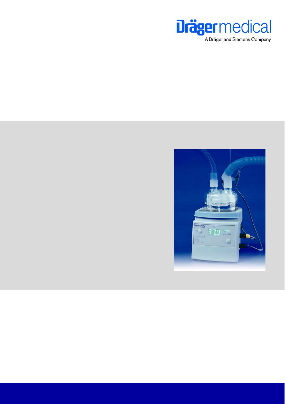
Technical Documentation
Fisher & Paykel® MR 850
Respiratory Humidifier
Revision 5.0
5697.500
9036209
Because you care


Contents
General
1 Symbols and Definitions 3
2 Notes 3
Function Description
1 MR 850 Respiratory Humidifier 7
1.1 Humidifier Operation ……………………………………………………………………………………………….. 7
1.2 Operating Modes …………………………………………………………………………………………………….. 8
1.2.1 Stand-by mode …………………………………………………………………………………………… 8
1.2.2 Intubated mode ………………………………………………………………………………………….. 8
1.2.3 Mask mode ………………………………………………………………………………………………… 8
1.3 Controls …………………………………………………………………………………………………………………. 9
1.3.1 On/off button ………………………………………………………………………………………………. 9
1.3.2 Mode button ………………………………………………………………………………………………. 9
1.3.3 Mute button ……………………………………………………………………………………………….. 9
1.4 Optical Indicators …………………………………………………………………………………………………… 10
1.4.1 Display …………………………………………………………………………………………………….. 10
1.4.2 Humidity alarm (lung symbol) ……………………………………………………………………… 10
1.4.3 Warning triangle alarm ………………………………………………………………………………. 10
1.5 Setup Indicators (LEDs) …………………………………………………………………………………………. 10
1.5.1 Temperature probes ………………………………………………………………………………….. 10
1.5.2 Heater wire adapter …………………………………………………………………………………… 10
K5697500IECIVZ.fm 10.05.06
1.5.3 Temperature probe connectors …………………………………………………………………… 11
1.5.4 Humidification chamber temperature probe alarm with probe connector alarm ….. 11
1.5.5 Airway temperature probe alarm with probe connector alarm ………………………….. 11
1.5.6 Water out LED ………………………………………………………………………………………….. 11
1.6 Operational Alarms ………………………………………………………………………………………………… 11
1.6.1 Humidity alarm (lung symbol) ……………………………………………………………………… 11
All rights reserved. Copyright reserved.
I

Contents
Annex
Parts catalog
Test List
K5697500IECIVZ.fm 10.05.06
All rights reserved. Copyright reserved.
II

General
1

2

Fisher & Paykel MR 850 General
1 Symbols and Defini-
tions
WARNING
A WARNING statement provides important information about a potentially hazardous situation which, if not avoided, could result in death
or serious injury.
CAUTION
A CAUTION statement provides important information about a potentially
hazardous situation which, if not avoided, may result in minor or moderate
injury to the user or patient or in damage to the equipment or other property.
NOTE
A NOTE provides additional information intended to avoid inconvenience
during operation.
Definitions according to German standard DIN 31051:
Inspection = examination of actual condition
Maintenance = measures to maintain specified condition
Repair = measures to restore specified condition
Servicing = inspection, maintenance, and repair
2Notes
This Technical Documentation conforms to the IEC 60601-1 standard.
Read each step in every procedure thoroughly before beginning any test.
Always use the proper tools and specified test equipment. If you deviate from
the instructions and/or recommendations in this Technical Documentation,
the equipment may operate improperly or unsafely, or the equipment could be
damaged.
It is our recommendation to use only Dräger parts and supplies.
The maintenance procedures described in this Technical Documentation may
be performed by qualified service personnel only. These maintenance procedures do not replace inspections and servicing by the manufacturer.
The information in this Technical Documentation is confidential and may not
be disclosed to third parties without the prior written consent of the manufacturer.
This Technical Documentation is for the purpose of information only. Product
descriptions found in this Technical Documentation are in no way a substitute
for reading and studying the Instructions for Use/Operating Manual enclosed
with the product at the time of delivery.
All rights reserved. Copyright reserved.
Version 3.0_ Released_Printed on_10.05.06_General_Technical_Documentation.fm
5697.500
3

General Fisher & Paykel MR 850
Know-how contained in this Technical Documentation is subject to ongoing
change through research and development and Dräger Medical reserves the
right to make changes to this Technical Documentation without notice.
NOTE
Unless otherwise stated, reference is made to laws, regulations or standards (as amended) applicable in the Federal Republic of Germany for
equipment used or serviced in Germany. Users or technicians in all other
countries must verify compliance with local laws or applicable international
standards.
Version 3.0_ Released_Printed on_10.05.06_General_Technical_Documentation.fm
All rights reserved. Copyright reserved.
4
5697.500

Function Description
5

6
Fisher & Paykel MR 850 Function Description
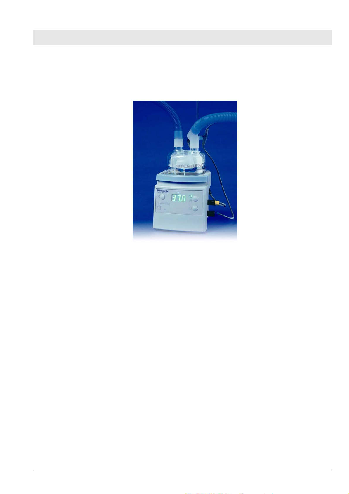
1 MR 850 Respiratory
Humidifier
The MR 850 Respiratory humidifier is designed to add heat and moisture to
the respiratory gas delivered to the patient. The humidifier can be connected
to various ventilators. It supports CPAP ventilation, delivery of other medical
gases, intubation and mask ventilation.
Figure 1 MR 850 Respiratory Humidifier
1.1 Humidifier Operation The respiratory gas flows into the humidification chamber. A heater plate
heats the sterile, pyrogen-free water contained in the humidification chamber.
The heater plate is located below the humidification chamber. The heated
water humidifies the respiratory gas. A temperature probe at the humidification chamber outlet measures the respiratory gas temperature. The measurement signal is transmitted to a control circuitry. This control circuitry controls
the amount of power delivered to the heater plate in order to maintain the respiratory gas temperature at a constant level.
The heated and humidified respiratory gas travels through the inspiratory
limb. The inspiratory limb has a heater wire inside. A temperature probe measures the patient’s respiratory gas temperature. The opening of this temperature probe is located at the end of the inspiratory limb near the patient. The
measurement signal from the temperature probe is transmitted to a control
circuitry. This control circuitry controls the power delivered to the heater wire
in order to maintain the respiratory gas temperature at the inlet and outlet of
the inspiratory limb at a constant level. This prevents the humidity contained
in the respiratory gas from condensing in the inspiratory limb.
An expiratory limb heater wire must also be used in order to stop the patient’s
expired humidity from condensing into the expiratory limb of the breathing circuit.
For internal use only. Copyright reserved.
Version 1.2_ Released_Printed on_10.05.06_F5697500T01.fm
5697.500
7

Function Description Fisher & Paykel MR 850
1.2 Operating Modes
1.2.1 Stand-by mode Depending on the severity of the alarm condition, the humidifier will either
enter stand-by mode or remove all power from the heating systems (heater
plate, heater wire(s)).
The humidifier will generate an audible alarm and always enter stand-by
mode if the following occurs:
– Malfunction/error during operation
– Incorrect settings
– Gas flow in breathing circuit stops
In stand-by mode the following occurs:
– Heater wire power is set to 30 %
– Heater plate temperature is limited to 60 °C
– Heater plate power is limited to 20 %
1.2.2 Intubated mode ”Intubated” is the default mode on power on of the humidifier. This mode is for
use with patients who need to be ventilated mechanically. The humidifier
delivers an optimally humidified respiratory gas of 44 mg/L to the patient. The
respiratory gas temperature is almost the same as the patient’s core temperature (37 °C).
If ambient conditions change, e.g. due to cold or drafts, the temperature can
be reduced in steps to 35 °C in order to prevent condensate buildup in the
inspiratory limb.
1.2.3 Mask mode ”Mask” mode is suitable for patients who are receiving gas via a face mask
(O2 therapy, CPAP). In this mode the patients receive respiratory gas that
has an adequate humidity level (to compensate for the unphysiologically high
gas flow rate).
Version 1.2_ Released_Printed on_10.05.06_F5697500T01.fm
For internal use only. Copyright reserved.
8
5697.500

Fisher & Paykel MR 850 Function Description
1.3 Controls
1.3.1 On/off button If the on/off button is held down briefly, the humidifier will toggle on or off.
After power-on the humidifier starts an internal diagnostic routine (self test).
An audible signals tells the user when the self test is completed.
1.3.2 Mode button When held down for one second, the mode button toggles the humidifier
between mask mode and intubated mode.
1.3.3 Mute button The mute button silences the humidifier’s audible alarm. The muted time
depends on the alarm condition and the type of alarm.
Both the chamber temperature and then the airway temperature can be displayed by pushing and holding the mute button for 1 second. The display will
return to airway temperature after a few seconds.
For internal use only. Copyright reserved.
Version 1.2_ Released_Printed on_10.05.06_F5697500T01.fm
5697.500
9

Function Description Fisher & Paykel MR 850
1.4 Optical Indicators
1.4.1 Display The display shows the saturation temperature of the delivered respiratory gas
in °C. Normally, it is the temperature of the humidification chamber (in intubated mode approx. 37 °C, in mask mode approx. 30 °C)
1.4.2 Humidity alarm (lung
symbol)
1.4.3 Warning triangle alarm The warning triangle indicates a serious hardware fault.
1.5 Setup Indicators
(LEDs)
1.5.1 Temperature probes These LEDs will light if the temperature probes (humidification chamber, air-
The humidifier will generate an audible and visual alarm if the temperature in
the humidification chamber is above 41 °C or the respiratory gas temperature
is above 43 °C.
The humidifier generates a visual and audible alarm if in intubated mode a
low level of humidity is being delivered to the patient for too long.
The humidity alarm may be caused by ambient conditions (cold, drafts) or
can result from too high or too low gas flow rates.
WARNING
If the warning triangle on the MR 850 Respiratory Humidifier comes
on, immediately take the humidification chamber and the breathing
circuit out of service.
The setup indicators (LEDs), placed on the lower left of the front panel, light
when the humidifier and its accessories are not set up correctly.
way) are not correctly plugged into the breathing circuit or the humidifier.
After power-on or fast changing of temperature values, the humidifier checks
whether the temperature probes are plugged in or not by first cooling down
then heating up the respiratory gas.
If the humidifier finds that either probe is not inserted into the breathing circuit, an alarm will be generated and the humidifier will enter stand-by mode.
During this alarm the humidifier will initiate a probe out test periodically, or a
test will be initiated immediately after mute has been pressed.
During periods of low or zero gas flow, the airway probe out alarm is disabled.
As soon as flow is detected however, an airway probe test is initiated.
1.5.2 Heater wire adapter The heater wired adapter indicator will light under the following conditions:
– Heater wire adapter not connected correctly
– Breathing circuit is faulty or not connected correctly
– There is an intermittent connection
– Excessive current in the heater wires (total current in all limbs greater
than 3.5 A)
The humidifier will remove power from the heating system if the heater wire
adapter alarm is active.
10
5697.500
Version 1.2_ Released_Printed on_10.05.06_F5697500T01.fm
For internal use only. Copyright reserved.

Fisher & Paykel MR 850 Function Description
1.5.3 Temperature probe connectors
1.5.4 Humidification chamber
temperature probe alarm
with probe connector
alarm
1.5.5 Airway temperature
probe alarm with probe
connector alarm
The temperature probe LEDs will light under the following conditions:
– Temperature probes are not connected correctly to the humidifier
– Temperature probes are faulty
The humidifier checks whether the temperature probes are open or short circuited.
The humidifier checks to see if the humidification chamber temperature probe
is faulty by testing for the following conditions:
– Humidification chamber temperature is greater than 80 °C.
– Humidification chamber temperature has been greater than 50 °C for 20
minutes.
If an apparent fault is found, the humidifier will give a probe connector alarm
and the LED of the humidification chamber temperature probe will light. The
humidifier will stay in stand-by mode until the temperature at the humidification chamber temperature probe drops below 50 °C.
The humidifier checks to see if the airway temperature probe is faulty by testing for the following conditions:
– Airway temperature is greater than 80 °C.
– Airway temperature has been greater than 50 °C for 5 minutes.
If an apparent fault is found, the humidifier will give a probe connector alarm
and the LED of the airway temperature probe will light. The humidifier will
stay in stand-by mode until the temperature at the airway temperature probe
drops below 50 °C.
1.5.6 Water out LED The water out LED indicates that there is insufficient water in the humidifica-
tion chamber.
The humidifier controls the amount of power required to maintain the set
chamber temperature at a constant level.
If a lower than expected amount of power is required, the humidifier will generate a visual and audible water out alarm.
With greater changes in flow it may take 15 minutes or longer to generate a
water out alarm.
The water out alarm can be cancelled for 1 minute by pressing the mute button. If however the water out condition remains, the humidifier will re-alarm.
1.6 Operational Alarms These alarms are generated if problems occur with the operation of the
humidifier.
1.6.1 Humidity alarm (lung
symbol)
A humidity alarm will occur if the displayed temperature is too high, or if the
delivered humidity (intubated mode only) has been low for a period of time.
The humidifier will generate a visual and audible alarm if the humidification
chamber temperature exceeds 41 °C or the airway chamber exceeds 43 °C.
If these high temperature alarms occur, the humidifier will immediately shut
down the heater wire and the heater plate.
For internal use only. Copyright reserved.
Version 1.2_ Released_Printed on_10.05.06_F5697500T01.fm
5697.500
11
Function Description Fisher & Paykel MR 850
Low humidity warning and alarm
The low humidity warning and alarm are disabled during warm-up and no flow
conditions.
The lung symbol lights when a low level of humidity is being delivered to the
patient. The audible alarm alerts the user that a low level of humidity has
been delivered to the patient for too long.
The humidification chamber temperature probe controls the humidity low
warning or alarm.
If the humidification chamber temperature is below 35.5 °C for 25 seconds,
the lung symbol will light. If the temperature remains below this level for too
long, then a low humidity alarm is activated.
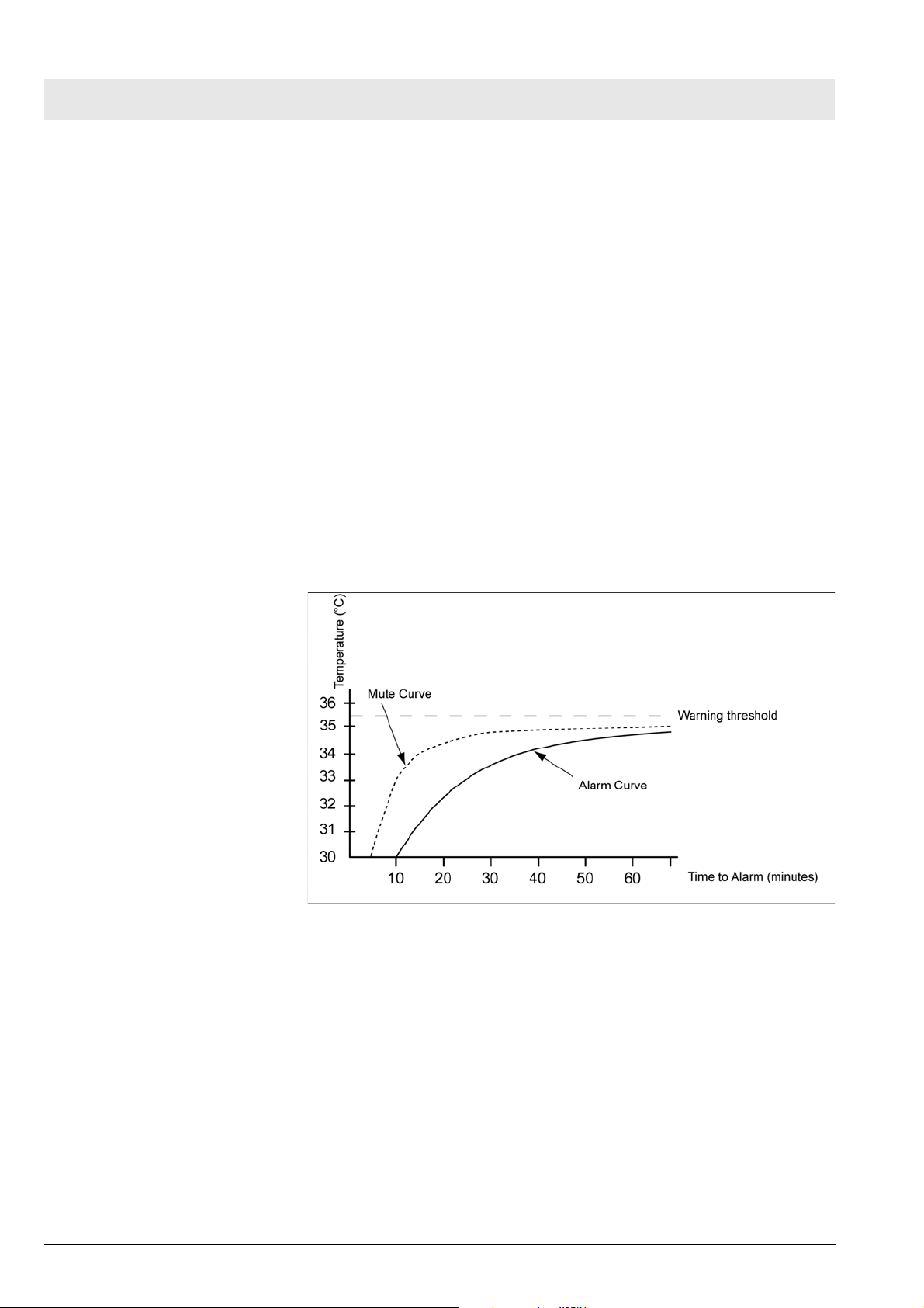
The time taken for the humidifier to alarm is dependent on how far below the
35.5 °C threshold the temperature is.
The following Figure shows the relationship between temperature and the
time before a warning or alarm is generated:
12
Figure 2 Temperature vs time to alarm
Pressing the mute button silences the audible low humidity alarm for 1 minute
if the same temperature of the humidification chamber temperature probe is
maintained.
The low humidity warning and alarm can occur under the following conditions:
–Cold
– Drafts
– Gas flow rates outside specification of breathing circuit
– Gas flow rates outside specification of humidification chamber
– Gas flow rates outside specification of humidifier.
5697.500
Version 1.2_ Released_Printed on_10.05.06_F5697500T01.fm
For internal use only. Copyright reserved.

Annex
Parts catalog
Test List


Parts catalog
Fisher&Paykel MR 850
Emergency Care — Perioperative Care — Critical Care — Perinatal Care — Home Care
Revision: 2006-03-20 08:50:13
5697.500
Because you care
Because you care

2
Temp.Sensoradapter
Parts catalog
Item
Part No. Description Qty.
No.
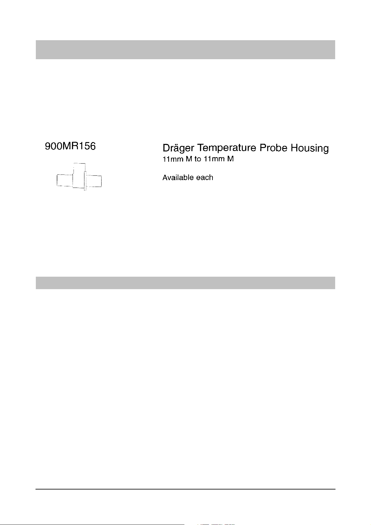
8411044 PROBE-THERMOMETER HOUSING DRAE 1.000 St
Qty.
unit
Remark
5697.500
Items that are shown in the illustration but are not listed below the illustration are not available as spare parts
Revision: 2006-03-20 08:50:13
3
Loading…
")

Рейтинг 5.00 из 5 на основе опроса 1 пользователя
(1 отзыв клиента)
174 450 руб.
Хотите цену ниже?
Увлажнитель дыхательной смеси Fisher & Paykel MR 850 способен обеспечить естественный баланс температуры и влажности, характерный для легких здорового человека в ситуации любого вида респираторной поддержки – инвазивной или неинвазивной вентиляции, терапии с увлажнением, высокоскоростной подачи кислорода.
Запросить КП и ТЗ / авторизовать проект – info@medpribor.pro
- Описание
- Характеристики
- Комплектация
- Отзывы (1)
- Доставка
- Вопрос-ответ
Описание
Описание Fisher & Paykel 850
При проведении респираторной поддержки увлажнитель дыхательной смеси выполняет ту же функцию, что верхние дыхательные пути при естественном дыхании – прибор согревает и увлажняет дыхательную смесь прежде, чем она попадет в нижние отделы легких.
Для обеспечения подогрева дыхательной смеси к увлажнителю подключается самозаполняющаяся камера и одноразовые дыхательные контуры пациента. Таким образом, система становится гибкой и может обеспечивать увлажнение дыхательной смеси для всех категорий пациентов во всех клинических ситуациях.

Увлажнитель имеет всего 2 режима работы, что значительно облегчает выбор. Режим оптимальной влажности обеспечивает подогрев дыхательной смеси до 37 градусов и влажности 44мг/л, что полностью соответствует параметрам самостоятельного дыхания здорового человека и обеспечивает физиологический баланс температуры и влажности. Режим необходимой влажности прогревает дыхательную смесь до 31 градуса и увлажняет до уровня 32 мг/л. Такой режим увлажнения оптимален для масочной вентиляции. Интенсивность увлажнения определяется количеством влаги, образующимся в носоглотке естественным путем.
Контроль влажности в дыхательном контуре и самозаполняющейся камере проводится независимо, что позволяет минимизировать конденсат в дыхательном контуре и достигнуть оптимальной влажности дыхательной смеси.
Увлажитель MR 850 обладает интеллектуальной технологией контроля за условиями окружающей среды, что позволяет уменьшать конденсацию в контуре в условиях различных температур.
ВНИМАНИЕ: Рекомендуемая температура окружающей среды от 18 до 26 ºC.
- Для всех возрастов
- Одной кнопкой выбирается оптимальный уровень температуры и влажности для взрослых, детей и новорожденных
- Простая установка с простым управлением и легко читаемый дисплей
- Усовершенствованные алгоритмы и способность ощущать поток оптимизирует доставку увлажнения и минимизирует ложные тревоги
- Автоматический режим ожидания во время периодов прерывания потока газа или воды
- Рекомендуемая температура окружающей среды: 18 – 26 °C
- Рекомендуемая скорость потока в инвазивном режиме: до 60 л/мин
- Рекомендуемая скорость потока в неинвазивном режиме: до 120 л/мин
- Увлажнение в инвазивном режиме: >33 мг/л
- Увлажнение в неинвазивном режиме: >10 мг/л
- Время прогрева: менее 30 мин
Видео-обзор увлажнителя Fisher & Paykel 850
Характеристики
Характеристики
| Производитель / Бренд |
Fisher&Paykel Helthcare |
|---|---|
| Гарантия |
12 месяцев |
| Страна производства |
Новая Зеландия |
Комплектация
| Аппарат Fisher & Paykel AIRVO™ 2 | 1 шт. |
|---|---|
| Инструкции по эксплуатации для пользователя | 1 шт. |
| Сетевой кабель | 1 шт. |
| Гарантийный талон | 1 шт. |
Отзывы (1)
Доставка
СПОСОБЫ ДОСТАВКИ:
- экспресс доставка в течении 5 часов собственным транспортом компании (Москва и область)
- курьерской службой или ТК по РФ и торговому союзу (до двери)
- до пунктов самовывоза
СПОСОБЫ ОПЛАТЫ: при получении или предоплата по счету
БЕСПЛАТНАЯ И ПЛАТНАЯ ДОСТАВКА:
- Бесплатная доставка медицинского оборудования при заказе от 10.000 рублей осуществляется по Москве и МО
- Бесплатная доставка медицинского оборудования при заказе от 60.000 рублей осуществляется по всей России
- Платная доставка заказов до 60.000 руб. осуществляется по всей России *
- Отправка заказов любой стоимостью в страны торгового союза осуществляется платно (в Казахстан, Беларусь и другие страны).
* Стоимость доставки до 60000 руб. рассчитывается в соответсвии с тарифами служб доставки (см. раздел доставки). Стоимость доставки зависит от габаритов товара и веса, подробный расчет вы можете получить у менеджеров интернет-магазина.
ДЛЯ КОНТРАКТНЫХ КЛИЕНТОВ: Мы осуществляем поставки медицинского оборудования оптом, в розницу и на тендерной основе. Для больниц, поликлиник, фондов и других организаций доставка, монтаж и обучение может быть включено в стоимость товара. (по желанию заказчика)
Вопрос-ответ
Вопросы и ответы покупателей
Еще не задано вопросов, будьте первым, кто спросит о товаре.
Похожие товары
-
Страница 1
MR850 RESPIRATORY HUMIDIFIER Technical Manual REVISION J Copyright ©2005 Fisher & Paykel Healthcare Ltd. Auckland, New Zealand[…]
-
Страница 2
MR850 Technical Manual * Revision J * Issued November 2005 * Ref. 185041 340 (185041713 internal) 2 Fisher & Paykel Healthcare Head Office: PO Box 14-348, Panmure, Auckland 1134 New Zealand Email: info@fphcare.com Web Site: www.fphcare.com Tel: +64-(0)9-574-0100 Fax: +64-(0)9-574-0158 France/Benelux: Parc Silic-Bal F, 10 Avenue de Quebec, Silic[…]
-
Страница 3
MR850 Technical Manual * Revision J * Issued November 2005 * Ref. 185041 340 (185041713 internal) 3 TABLE OF CONTENTS 1 INTRODUCTION ……………………………………………………………………………………………………. …………..7 1.1 A BOUT THIS M ANUAL …………………………………………………….[…]
-
Страница 4
MR850 Technical Manual * Revision J * Issued November 2005 * Ref. 185041 340 (185041713 internal) 4 6 TROUBLESH OOTING …………………………………………………………………………………………………. ….. 24 6.1 O PERATIONAL P ROBLEMS ……………………………………………………………………….[…]
-
Страница 5
MR850 Technical Manual * Revision J * Issued November 2005 * Ref. 185041 340 (185041713 internal) 5 Revision Description of Technical Manual Cha nge Date Issued A First release technical manual. Covers Revision A PCB’s ONLY . 12 Jan. 1999 B Second release technical manual. Covers Revision C and later PCB’s ONLY . 6 May 1999 C Add “View850” […]
-
Страница 6
MR850 Technical Manual * Revision J * Issued November 2005 * Ref. 185041 340 (185041713 internal) 6 Revision Description of Technical Manual Change Date Issued J 1.4 Product Application, Add warni ng to connect humi difier only to a pure sine wave po wer source 5.2 Safety Check, add CAUTION: and NOT E: 6.3 “See manual” Error codes, Elaborate th[…]
-
Страница 7
MR850 Technical Manual * Revision J * Issued November 2005 * Ref. 185041 340 (185041713 internal) 7 Introduction 1.1 About this Manual This manual is intended for qualified servic e personnel who will perform maintenance and servicing on the Fisher & Paykel Healthcare MR850 Respiratory Humidifier. This manual covers the product specifications, […]
-
Страница 8
MR850 Technical Manual * Revision J * Issued November 2005 * Ref. 185041 340 (185041713 internal) 8 Expiratory Limb The section of the breathing circuit that takes th e expired gases from the patient. 1.3 Definitions NOTE : A NOTE provides important information or ex planation of procedures or conditions which may otherwise be misinterpreted or ove[…]
-
Страница 9
MR850 Technical Manual * Revision J * Issued November 2005 * Ref. 185041 340 (185041713 internal) 9 2 Humidifier Symbols Caution: Hot surfaces may exceed 85 °C Power On/Off (stand by) Type BF Invasive Mode Attention – consult accompanying documents Non-invasive mode Alternating Current Temperature Alarm Drip proof protection to IPX1 Serial Port […]
-
Страница 10
MR850 Technical Manual * Revision J * Issued November 2005 * Ref. 185041 340 (185041713 internal) 10 3 Specifications 3.1 Mechanical Dimensions: 140 mm x 173 x 135 (without chamber fitted) Weight: 2.8 kg (without chamber fitted) Approx. 3.1 kg (with chamber fitted, and filled with water) 3.2 Electrical MR850 Model Number Supply Voltage Supply Curre[…]
-
Страница 11
MR850 Technical Manual * Revision J * Issued November 2005 * Ref. 185041 340 (185041713 internal) 11 Non-heater wire operation: Invasive Mode: Airway temperature < 29.5 °C causes an audible and visible alarm. Non-invasive Mode: Airway temperature < 26.0 °C causes an audible and visible alarm. Sound Pressure Level: Alarms exceed 50 dBA @ 1 m[…]
-
Страница 12
MR850 Technical Manual * Revision J * Issued November 2005 * Ref. 185041 340 (185041713 internal) 12 4 Operating Modes and Controls 4.1 Humidifier Operation The MR850 humidifier is designed to add heat and moisture to respiratory gases. The gas is passed through a humidification chamber where it is warmed and humidified. The MR850 has two heating s[…]
-
Страница 13
MR850 Technical Manual * Revision J * Issued November 2005 * Ref. 185041 340 (185041713 internal) 13 4.1.2 Non-Heater Wire Operation (Software version 7.23 only) Figure 4.2 Typical Non-Heater Wire Humidifier Setup In this application the MR850 maintains the airway temperature at the desired set point (invasive 37 °C or non-invasive 31 °C) by heat[…]
-
Страница 14
MR850 Technical Manual * Revision J * Issued November 2005 * Ref. 185041 340 (185041713 internal) 14 Stand-by (Software versions: 5.45 & 5.70) • Heater wire power is set at 30 %. • Control of chamber temperature is attempted, within the following limits: • Heater plate temperature is limited to 60 °C. • Heater plate power is limited to[…]
-
Страница 15
MR850 Technical Manual * Revision J * Issued November 2005 * Ref. 185041 340 (185041713 internal) 15 then the chamber set point will automatically be increased in 0.5 °C steps (1 °C steps for non- invasive mode) until the minimum power is achieved. The maximum amount of compensation applied is either 3 or 5 °C depending on the mode and software […]
-
Страница 16
MR850 Technical Manual * Revision J * Issued November 2005 * Ref. 185041 340 (185041713 internal) 16 connected. Breathing circuit recognition is performed via three electrical connections on the heater wire adaptor. Re-configuring the electrical connection pins on a h eated circuit and the way it connects to this adaptor identifies the type of heat[…]
-
Страница 17
MR850 Technical Manual * Revision J * Issued November 2005 * Ref. 185041 340 (185041713 internal) 17 4.2.3 Mute Button The mute button silences the humidifier’s audible alarm. The muted time depends on the alarm condition. In general, alarms will be muted for 2 minutes. A chamber or airway probe alarm is muted for a longer time, until the humi[…]
-
Страница 18
MR850 Technical Manual * Revision J * Issued November 2005 * Ref. 185041 340 (185041713 internal) 18 4.4.2 Temperature / Flow Probe Connector This indicator will light if the temperature probe is not corre ctly plugged in, or the probe used is faulty. The humidifier tests for the following probe fault conditions: • Temperature probe disconnected […]
-
Страница 19
MR850 Technical Manual * Revision J * Issued November 2005 * Ref. 185041 340 (185041713 internal) 19 4.4.5 Water Out Indicator This indicates that there is insufficient water in the humidification chamber. The humidifier measures the amount of power used to obtain the chamber temperature. If a lower than expected amount of power is used, a ‘wa[…]
-
Страница 20
MR850 Technical Manual * Revision J * Issued November 2005 * Ref. 185041 340 (185041713 internal) 20 Figure 4.3 Temperature vs Time to Alarm Pressing mute during a temperature alarm silences the alarm for half the normal time period, if the same temperature is maintained. The low temperature warning and alarm can be caused by cold or drafty ambient[…]
-
Страница 21
MR850 Technical Manual * Revision J * Issued November 2005 * Ref. 185041 340 (185041713 internal) 21 5 Maintenance Procedures In order to keep your humidifier in good worki ng order, it is necessary to perform maintenance at regular intervals. 5.1 Maintenance Schedule 5.1.1 MR850 Humidifier Annually a. Check MR850 for physical damage: • Check the[…]
-
Страница 22
MR850 Technical Manual * Revision J * Issued November 2005 * Ref. 185041 340 (185041713 internal) 22 5.2 Safety Check The unit should be tested to the current medical electrica l standards for in-house testing for each specific country (example, refer to AS/NZS 3551 for Australia and New Zealand). CAUTION: Permanent damage to this humidifier will r[…]
-
Страница 23
MR850 Technical Manual * Revision J * Issued November 2005 * Ref. 185041 340 (185041713 internal) 23 5.3 Cleaning Instructions 5.3.1 MR850 Humidifiers It is recommended that only the following cleaners be used on the MR850 as at the time of revision of this technical manual. The disinfectants in the list below have been tested to ensure that no dam[…]
-
Страница 24
MR850 Technical Manual * Revision J * Issued November 2005 * Ref. 185041 340 (185041713 internal) 24 6 Troubleshooting 6.1 Operational Problems This section deals with faults that cause the humidifier to alarm. This may be caused by incorrect setup, faulty accessories, or a faulty humidifier. Refer below for troubleshoo ting. Symptom Corrective Act[…]
-
Страница 25
MR850 Technical Manual * Revision J * Issued November 2005 * Ref. 185041 340 (185041713 internal) 25 Symptom Corrective Action Reference Heater wire alarm not working Non-heater wire mode has been a ctivated, connect a heated wire circuit or disable this mode via the diagnosti c menu. Section 4.1.2 1. Check that the airway probe is inserted into th[…]
-
Страница 26
MR850 Technical Manual * Revision J * Issued November 2005 * Ref. 185041 340 (185041713 internal) 26 Symptom Corrective Action Reference 1. Make sure the humidifier h as had time to warm up and that there is sufficient gas flow through the b reathing circuit. 2. The humidifier cannot maintain temperature. If the temperature indicator is also on the[…]
-
Страница 27
MR850 Technical Manual * Revision J * Issued November 2005 * Ref. 185041 340 (185041713 internal) 27 6.3 “See Manual” Error Codes The following is an explanation of the error codes that are displayed in conjunction w ith the See Manual indicator flashing. A code is not displayed if the microprocessor has stopped functioning (see technical probl[…]
-
Страница 28
MR850 Technical Manual * Revision J * Issued November 2005 * Ref. 185041 340 (185041713 internal) 28 Error Description of Fault E41 Failed the functional test at time of manufacture E42 Was not stress tested during manufacture E43 Failed the stress test during manufacture E44 Not tested on functional tester 2 E45 Failed production functional tester[…]
-
Страница 29
MR850 Technical Manual * Revision J * Issued November 2005 * Ref. 185041 340 (185041713 internal) 29 6.4 Diagnostic Menu By pressing the mute and mode buttons together for 1 second, the diagnostic menu is entered, indicated by the display of two rows of dashes ‘= = =’. Releasing both bu ttons will allow the diagnostic menu to cycle automaticall[…]
-
Страница 30
MR850 Technical Manual * Revision J * Issued November 2005 * Ref. 185041 340 (185041713 internal) 30 6.4.2 Diagnostic Menu for Software Version 6.00 Display Description HC Humidity Compensation (HC) algorith m Invasive mode, compensation range is 0.0 to 3.0 °C ( CSP = 37.0 to 40 °C ) Non-Invasive mode, compensation ran ge is 0.0 to 5.0 °C ( CSP […]
-
Страница 31
MR850 Technical Manual * Revision J * Issued November 2005 * Ref. 185041 340 (185041713 internal) 31 6.4.3 Diagnostic Menu for Software Version 7.00 & 7.21 Display Description HC Humidity Compensation (HC) algorith m Invasive mode, compensation range is 0.0 to 3.0 °C ( CSP = 37.0 to 40 °C ) Non-Invasive mode, compensation ran ge is 0.0 to 5.0[…]
-
Страница 32
MR850 Technical Manual * Revision J * Issued November 2005 * Ref. 185041 340 (185041713 internal) 32 6.4.4 Diagnostic Menu for Software Version 7.14 Display Description HC Humidity Compensation (HC) algorithm Note: HC is inactive while operating under non-he ater wire control. Invasive mode, compensation range is 0.0 to 5.0 °C ( CSP = 37.0 to 42 ?[…]
-
Страница 33
MR850 Technical Manual * Revision J * Issued November 2005 * Ref. 185041 340 (185041713 internal) 33 6.4.5 Diagnostic Menu for Software Version 7.22 Display Description HC Humidity Compensation (HC) algorithm Note: HC is inactive while operating under non-he ater wire control. Invasive mode, compensation range is 0.0 to 5.0 °C ( CSP = 37.0 to 42 ?[…]
-
Страница 34
MR850 Technical Manual * Revision J * Issued November 2005 * Ref. 185041 340 (185041713 internal) 34 6.4.6 Diagnostic Menu for Software Version 7.23 Display Description Cct Connected breathing circuit identification: “S“ = Standard inspiratory heater conn ected “C” = Coaxial inspiratory heater connected “E” = Expiratory heater connected[…]
-
Страница 35
MR850 Technical Manual * Revision J * Issued November 2005 * Ref. 185041 340 (185041713 internal) 35 7 Servicing Procedures 7.1 General Considerations WARNING: Although the MR850 display may not be illuminated, the unit may still be energized. Be sure to disconnect the MR850 from the power supply before servicing. All servicing procedures should be[…]
-
Страница 36
MR850 Technical Manual * Revision J * Issued November 2005 * Ref. 185041 340 (185041713 internal) 36 Figure 7.2 Showing PCB fasteners 7.2.2 Replacing Fuses 1. Open the case (section 7.2.1). 2. The fuses can now be accessed. See Figure 7.3 for the location of the fuses on the power PCB. Figure 7.3 Showing location of the fuses on po wer PCB The four[…]
-
Страница 37
MR850 Technical Manual * Revision J * Issued November 2005 * Ref. 185041 340 (185041713 internal) 37 MR850 Model Number Supply Voltage Fuse Type Part Number MR850Jxx 115 V~ F1: 1 A 250 V FastBlow F2: 4 A 125 V FastBlow F3: 3 A 250 V FastBlow F4: 3 A 250 V FastBlow 999 830 001 999 830 017 999 830 012 999 830 012 MR850Gxx 100 V~ F1: 1 A 250 V FastBlo[…]
-
Страница 38
MR850 Technical Manual * Revision J * Issued November 2005 * Ref. 185041 340 (185041713 internal) 38 Figure 7.4 Showing Humidifier Power PCB w iring 7.2.4 Replacement of Transformer 1. Open the case (section 7.2.1). 2. Disconnect the transformer primary and secondary harnesses attached to the power PCB. 3. Unscrew the four mounting screws fixing th[…]
-
Страница 39
MR850 Technical Manual * Revision J * Issued November 2005 * Ref. 185041 340 (185041713 internal) 39 3. If the thermal cutout «clicks» when pushed, it has been previously activated, and is now reset. NOTE : If the heater plate is still hot, it must be allowed to cool suf ficiently before the thermal cutout will reset. 4. Close the case (s[…]
-
Страница 40
MR850 Technical Manual * Revision J * Issued November 2005 * Ref. 185041 340 (185041713 internal) 40 Figure 7.7 Showing location of Heater Plate Thermistor Thermal Cutout and Element Scre ws 8. Solder the wires from the new harness to the heater plate thermal cutout. 9. Attach the cable ties provided to the heater plate harness. 10. Place heater pl[…]
-
Страница 41
MR850 Technical Manual * Revision J * Issued November 2005 * Ref. 185041 340 (185041713 internal) 41 5. Remove the heater element, leaving the mica insulator in place. 6. Insert the new element into position, making sure the insulating mica is between the element and the heater plate. 7. Replace the element cover, using the four screws that were pr[…]
-
Страница 42
MR850 Technical Manual * Revision J * Issued November 2005 * Ref. 185041 340 (185041713 internal) 42 7.2.6 Installing New Software NOTE : A software upgrade kit is required. Some software may not be available in your country. Refer to your local Fisher & Paykel Healthcare representative for the appropriate part number: Single ROM pack 32 ROM Pa[…]
-
Страница 43
MR850 Technical Manual * Revision J * Issued November 2005 * Ref. 185041 340 (185041713 internal) 43 6. Apply mains power to the humidifier, while keeping the production test button depressed. The display should read: “PTS”. This ensures that the new software version number will be properly updated in the EEPROM. 7. Turn off the mains power to […]
-
Страница 44
MR850 Technical Manual * Revision J * Issued November 2005 * Ref. 185041 340 (185041713 internal) 44 8 Performance Testing This section discusses the performance testing of the MR850 humidifier and also the MR850 temperature / flow probe. Performance testing is required as part of ongoing maintenance or after servicing of the humidifier has been co[…]
-
Страница 45
MR850 Technical Manual * Revision J * Issued November 2005 * Ref. 185041 340 (185041713 internal) 45 1. Hold down the power button, then apply mains power to the humidifier. This action places the humidifier into service mode. 2. Select service mode number 1 (Calibration Probe #1 Check) by pushing the mute button when ‘-1-‘ is displayed. […]
-
Страница 46
MR850 Technical Manual * Revision J * Issued November 2005 * Ref. 185041 340 (185041713 internal) 46 8.1.4 Humidifier Voltage Calibration Check This check is required when the humidifier’s PCBs have been serviced or replaced, or if the mains transformer has been replaced. Equipment Required: • An AC voltmeter, capable of measuring RMS mains […]
-
Страница 47
MR850 Technical Manual * Revision J * Issued November 2005 * Ref. 185041 340 (185041713 internal) 47 3. Connect the humidifier chamber inlet to the gas supply, and turn the humidifier on. 4. Wait approximately 30 minutes for the humidifier to stabilise. Chamber and Airway temperatures can be check ed by using the display mode (section 4.3.1) and se[…]
-
Страница 48
MR850 Technical Manual * Revision J * Issued November 2005 * Ref. 185041 340 (185041713 internal) 48 1. Perform a humidifier calibration check as outlined in section 8.1.2 (ignore this step if recently completed). 2. Set up the humidifier as shown in Figure 4.1. Make sure the chamber probe is correctly inserted into the breathing circuit. 3. Connec[…]
-
Страница 49
MR850 Technical Manual * Revision J * Issued November 2005 * Ref. 185041 340 (185041713 internal) 49 9 Recommended Maintenance Checklist This sheet can be copied and used to keep a record of the maintenance procedures carried out on your MR850 Humidifier(s), and probes. Place the serial number and the date that the maintenance was carried out in th[…]
-
Страница 50
MR850 Technical Manual * Revision J * Issued November 2005 * Ref. 185041 340 (185041713 internal) 50 (Blank)[…]
-
Страница 51
MR850 Technical Manual * Revision J * Issued November 2005 * Ref. 185041 340 (185041713 internal) 51 10 Spare Parts Should any parts of the humidifier requ ire replacement, the following parts list is provided. Refer to the exp loded diagram on the opposite pa ge for part identification. Item Part Number Description 1 043 041 247 100 V~ Heater Plat[…]
-
Страница 52
MR850 Technical Manual * Revision J * Issued November 2005 * Ref. 185041 340 (185041713 internal) 52[…]
-
Страница 53
MR850 Technical Manual * Revision J * Issued November 2005 * Ref. 185041 340 (185041713 internal) 53 Heater Plate Assembly Item Part Number Description 1 614 040 861 Screw (M4x12) 2 641 040 829 Reflector 3 336 060 149 Reflector Spacer Washers 4 641 040 707 Element Cover 5 331040 114 Mica Insulator 6 614 040 327 Thermistor Screw 7 614 040 117 Earth […]
-
Страница 54
MR850 Technical Manual * Revision J * Issued November 2005 * Ref. 185041 340 (185041713 internal) 54[…]
-
Страница 55
MR850 Technical Manual * Revision J * Issued November 2005 * Ref. 185041 340 (185041713 internal) 55 11 Calibration Probe The information presented here refers to the construction of the MR850 Calibration Probe. This information is provided so that the probe can be checked for correct oper ation if required. The calibration probe consists of two Re[…]
-
Страница 56
MR850 Technical Manual * Revision J * Issued November 2005 * Ref. 185041 340 (185041713 internal) 56 12 Serial Port & Logging Software 12.1 INTRODUCTION The View850 software* is intended for use with the Fisher & Paykel Healthcare MR850 Respiratory Humidifier. The software can be used to display humidifier data and log the results to a file[…]
-
Страница 57
MR850 Technical Manual * Revision J * Issued November 2005 * Ref. 185041 340 (185041713 internal) 57 12.3.2 Logging Humidifier Data to File The View850 software can log the data it receives to a text file. This text file can then be opened at a later date (by programs such as Microsoft Excel), in order to review humidifier performance. In order to […]
-
Страница 58
MR850 Technical Manual * Revision J * Issued November 2005 * Ref. 185041 340 (185041713 internal) 58 13 EMC INFORMATION WARNING: The use of accessories other than those specified by Fisher & Paykel Healthcare may result in increased emissions or decreased immunity of the equipment or system. Guidance and manufacturer’s declar ation – electr[…]
-
Страница 59
MR850 Technical Manual * Revision J * Issued November 2005 * Ref. 185041 340 (185041713 internal) 59 Guidance and manufacturer’s declar ation – electromagnetic immunity The MR850 is intended for use in the electromagnetic environment s pecified below. The customer or the user of the MR850 should assure that it is used in such an environment. Im[…]
-
Страница 60
MR850 Technical Manual * Revision J * Issued November 2005 * Ref. 185041 340 (185041713 internal) 60 14 Product Change History Due to upgrades performed on delivered MR850 Respiratory Humidifiers, software and hardware versions are listed below. It should be realised that possible future upgrades may change the operation of the Humidifier. Please n[…]
-
Страница 61
MR850 Technical Manual * Revision J * Issued November 2005 * Ref. 185041 340 (185041713 internal) 61 History Change for model GJU PCB Version Software Version Introduction Serial Number Comments A 4.40 19 September 1998 9885xxx00000 First production release. A 4.44 22 October 1998 Software upgrade. C 5.12 12 April 1999 9985xxx00053 Release of new P[…]
-
Страница 62
MR850 Technical Manual * Revision J * Issued November 2005 * Ref. 185041 340 (185041713 internal) 62 History Change for all model except JHU & GJU PCB Version Software Version Introduction Serial Number Comments A 4.40 19 September 1998 9885xxx00000 First production release. A 4.44 22 October 1998 Software upgrade. C 5.12 12 April 1999 9985xxx0[…]
Fisher and Paykel MR850 Service manual
- Addeddate
- 2020-05-20 07:44:43
- Classification
- Clinical;Respiratory Humidifier;Fisher and Paykel Humidifier;Fisher and Paykel MR850
- Identifier
- manual_Fisher_and_Paykel_MR850_Service_manual
- Identifier-ark
- ark:/13960/t5x728p9b
- Ocr
- ABBYY FineReader 11.0 (Extended OCR)
- Page_number_confidence
- 73.91
- Ppi
- 300
- Scanner
- Internet Archive Python library 1.9.0
comment
Reviews
There are no reviews yet. Be the first one to
write a review.
576
Views
DOWNLOAD OPTIONS
Temporarily Unavailable
DAISY
For users with print-disabilities
Temporarily Unavailable
EPUB
Uploaded by
Sketch the Cow
on
Download
MR850 RESPIRATORY
HUMIDIFIER
Technical Manual
REVISION J
Copyright ©2005 Fisher & Paykel Healthcare Ltd.
Auckland, New Zealand