
Инструкция Suunto PM-5/1520 PC (Высотомер)
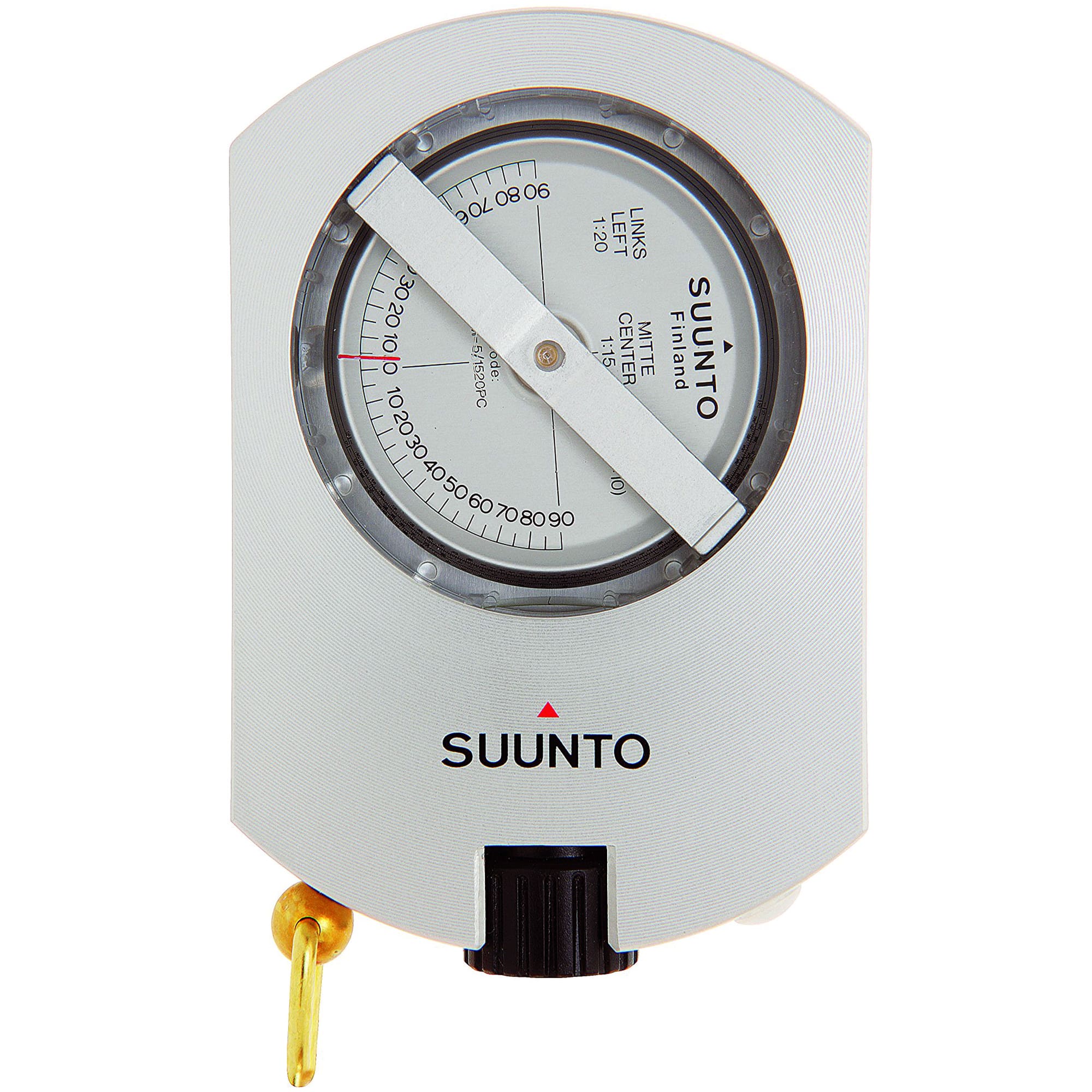
Suunto PM-5/1520 — это инструмент для измерения высоты, особенно высоты деревьев, с высокой точностью и скоростью. Корпус прибора выполнен из коррозионно-стойкого анодированного алюминиевого сплава, что гарантирует прочность и продлевает срок эксплуатации.
Suunto PM-5/1520 PC (Высотомер)
Page 1 of 1
Официальная гарантия
Мы являемся официальными дилерами, поэтому вся продукция в магазине продается только с
официальной гарантией в России.
Профессиональная консультация
Все наши консультанты эксперты. Они помогут Вам подобрать лучшую модель спортивного гаджета из основных брендов Polar, Garmin, Suunto, Coros.
Экспресс-доставка
Доставка по Москве, Санкт-Петербургу, Екатеринбургу в день заказа бесплатно. По России срок от 2-5 дней. Примерная стоимость 350-500 руб.
Рассрочка 0%
Беспроцентная рассрочка от ведущих банков. Без первоначального взноса. Онлайн оформление за
15 минут. Удаленное подписание с регионами РФ.
С помощью высотомера Suunto PM-5/1250 можно точно и быстро измерять высоту деревьев. Наводка и взятие отсчета по шкале происходят одновременно. Регулирование или блокировка шкалы не требуются. На высотомере имеются шкалы для измерения высоты с расстояния 15 и 20 м.
Корпус высотомера Суунто изготовлен из анодированного корозиостойкого легкий металла. Ось диска-стрелки установлена на камне из сапфира, что обеспечивает повышенную надежность и легкость вращения.
Шкальный барабан, посаженный на специальный подшипник, расположен в прозрачной герметически закрытой, наполненной специальной жидкостью пластмассовой коробке. Благодаря гасительной жидкости, вибрация, мешающая взятию отсчета, почти отсутствует, шкальный барабан двигается плавно и движение быстро прекращается. Жидкость незамерзающая и сохраняет гасящую способность во всех рабочих условиях.
Комплектация:
Высотомер Suunto PM-5.
Чехол из прочного нейлона, с петлей для крепления на поясе.
Красный капроновый шнур.
Вы также можете купить высотомер в комплекте с дополнительным защитным чехлом, описание которого находится по ссылке ниже:
Дополнительно — защитный чехол
Другие высотомеры в нашем ассортименте:
Высотомер ЭТ-1

EN | FR | DE | ES | IT | FI | SV
PM-5 / PM-5/1520

CUSTOMER SERVICE CONTACTS
COORDONNÉES DU SERVICE CLIENTS, KUNDENDIENSTE, DATOS DE CONTACTO DE ATENCION
AL CLIENTE, NUMERI UTILI PER IL SERVIZIO CLIENTI, KLANTENSERVICE, ASIAKASPALVELUN
YHTEYSTIEDOT, KUNDSERVICE, KONTAKTER
Global Help Desk +358 2 284 11 60
Suunto USA Phone +1 (800) 543-9124
Canada Phone +1 (800) 776-7770
Suunto website
COPYRIGHT
This publication and its contents are proprietary to Suunto Oy.
Suunto, Wristop Computer, Suunto PM-5, PM-5/1520 and their logos are registered
or unregistered trademarks of Suunto Oy. All rights reserved.
While we have taken great care to ensure that information contained in this
documentation is both comprehensive and accurate, no warranty of accuracy is
expressed or implied. Its content is subject to change at any time without notice.
www.suunto.com

Suunto PM-5, PM-5/1520
USER’S GUIDE
EN

TABLE OF CONTENTS
PM-5/1520 …………………………………………………………………………………………………. 4
OPTICAL HEIGHT METER ……………………………………………………………………..4
INSTRUCTIONS FOR USE …………………………………………………………………….4
MEASUREMENT OF HEIGHT …………………………………………………………………5
INSTRUCTIONS FOR USE OF NOMOGRAM …………………………………………..6
ESTABLISHING THE BASIC DISTANCE …………………………………………………. 6
PM-5 …………………………………………………………………………………………………………. 8
OPTICAL READING CLINOMETER …………………………………………………………8
AVAILABLE PM-5 VERSIONS …………………………………………………………………9
INSTRUCTIONS FOR USE ………………………………………………………………….. 10
NOMOGRAPHICAL HEIGHT CORRECTION ………………………………………….. 15
INSTRUMENT BODY COVER FOR SUUNTO KB-14 AND PM-5 ……………….16
3

PM-5/1520
OPTICAL HEIGHT METER
Suunto Height Meter PM-5/1520 is an instrument for measuring heights, especially
heights of trees, with great accuracy and speed. The body of the instrument is
corrosion-resistant anodized aluminium-alloy. The scale card runs on a special
bearing in a hermetically sealed plastic container filled with a liquid which guarantees
that it runs freely and stops quickly. The liquid will not freeze, retains full damping
properties in working conditions and eliminates irritating scale vibrations.
INSTRUCTIONS FOR USE
When measured from distances of 15 m a nd 20 m, tree heights can be read straight
off the instrument’s scales. The readings should be doubled when measuring from
distances of 30 m and 40 m. The Suunto Height Meter can also be used to determine
the angle of a gradient. This is done by taking a sighting along the line of a gradient
using the 20 m scale on the left of the instrument. The reading obtained can be
checked in the conversion table on the back of the instrument to obtain the angle.
4

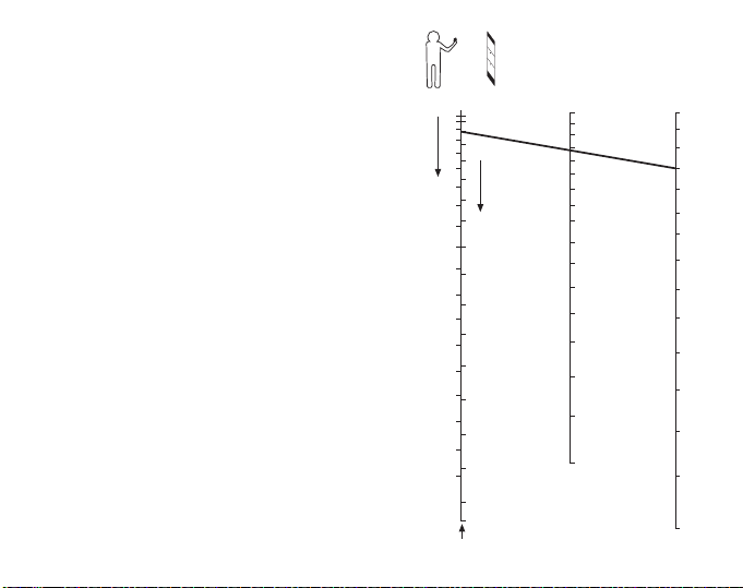
MEASUREMENT OF HEIGHT
The actual measurement of the height
of the tree should be done from the
distance measured in the following
way: the observer sights the top of the
tree with both eyes open. The object
sighted, the hair line and the scale will
all be simultaneously visible in the
instrument`s field of vision. As soon
as the hairline coincides with the top
of the tree, the tree height can be read
off (in this example, from the 20 m
scale on the left of the instrument).
The reading obtained is the height of
the tree measured from the eye level
of the observer. The base of the tree
remains to be sighted. If this is
situated below the eye level of the
observer, then the actual height of the
tree is obtained by adding the two
readings together. If it is above the
observer`s eye level, the tree height is
obtained by taking the difference
between the two readings. In fact, in
the latter case the distance cannot be
measured horizontally. Thus, to get
5
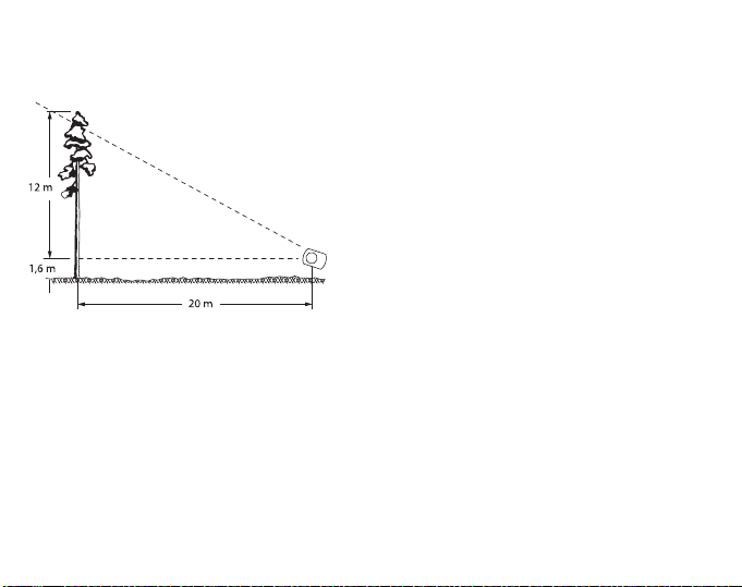
exactly correct result you have to proceed as stated below. On level ground, the tree
top readings is usually sufficient: one only has to add the height of the observer`s eye
level (1.60 m in this case), which is already known.
INSTRUCTIONS FOR USE OF
NOMOGRAM
If the distance, because of very uneven
ground, cannot de determined horizontally
as stated above, the nomogram on page 7
should be used.
ESTABLISHING THE BASIC DISTANCE
Because this instrument does not incorporate a prism, the basic distance e.g. 15 m
has to be determined using a tape measure along the ground. Take the top and base
readings and add or subtract them to get the apparent height. On the nomogram on
page 7, locate the apparent height on the right hand scale. On the double scale on
the left, locate the reading obtained from sighting the base of the tree. Note that
readings for falling and rising gradients should be taken from different sides of the
scale. Connect these two points of the nomogram with a straight line. The centre
scale of the nomogram now indicates the true height of the tree.
6
Important notice
Uphill
Base reading
16
15
14
13
12
11
10
9
8
7
6
5
4
3
2
1
0
21
20
19
18
17
16
15
14
13
12
11
10
9
8
7
6
5
4
2
6
7
8
9
10
11
12
13
14
15
16
17
18
19
20
m
Apparent height
4
5
6
7
8
9
10
11
12
13
14
15
16
17
18
19
20
m
Corrected height
L-20
m
Downhill
The axes of the eyes of some people are
not parallel, a condition called heterophoria. This can even vary in time and be
dependent on different factors too. Therefore, in order to be sure that said phenomenon does not affect the accuracy of
readings, it is suggested that the user
checks this possibility before taking the
actual readings as follows: Take a reading
with both eyes open and then close the
free eye. If the reading does not change
appreciably there is no disalignment of the
eye axes, and both eyes can be kept
open. Should there be a difference in the
readings, keep the other eye closed and
sight halfway to the side of the instrument
body. This will create an optical illusion
whereby the hairline continues past the
instrument body and is seen against the
target.
7
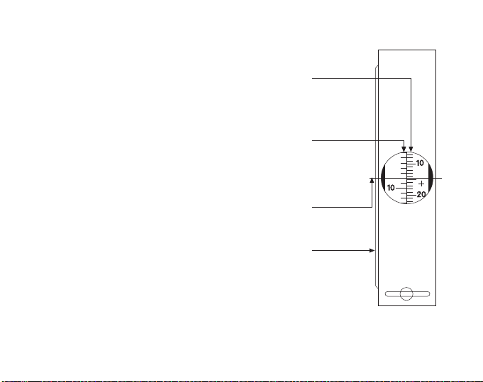
PM-5
+ and –
ft. scales
Additional
degree scale
in side window
Cross-hair
extended by
optical illusion
+ and –
degree scales
OPTICAL READING CLINOMETER
The sturdy pocket-size construction renders the
SUUNTO CLINOMETER most suitable for every type of
work. Easy for rapid reading through a parallax-free
lens is incorporated into the design.
Sighting and scale reading are done simultaneously.
There are no screws to turn, no bubbles to center, and
nothing to adjust.
Where space is limited, as in geological and
mineralogical work, the inclination of strata and other
formations can be read placing the instrument along the
contour or surface of the formation and reading the
angle directly through the side window.
Construction features
The framework is of corrosion resistant light-weight
aluminum.
The scale card is supported by a jewel bearing
assembly and all moving parts are immersed in a
damping liquid inside a high strength hermetically
sealed plastic container. The liquid dampens all undue
scale vibrations and permits a smooth shockless
movement of the scale card.
The material of the container is not attacked by sunlight or water. The liquid does not
freeze in the arctic or evaporate in the tropics.
8

Specifications
Weight: 120 g / 4.2 oz. Dimensions: 74 x 52 x 15 mm / 2 3/4″ x 2″ x 5/8″. The optical
scales are graduated in degrees from 0° to ±90°, and 0 % to ±150 %.
A table of cosines is imprinted on the back of the instrument.
Resolution
Can be read directly to one degree or one per cent. Can be estimated to 10 minutes
or 1/5 of 1 per cent, the latter naturally applying to readings around the zero level.
AVAILABLE PM-5 VERSIONS
The basic PM-5/360 PC has been modified by fitting it with different scale
combinations for special uses. Thus there is available a version with a ”new degree”
or grade scale. Here, instead of the normal 360-degree division, the full circle is
divided into 400 grades (g). The per cent scale there alongside is normal. The model
is PM-5/400 PC.
9

INSTRUCTIONS FOR USE
Readings are usually taken with the right eye. Owing to differences in the keenness of
the sight of the eyes and because of personal preferences the use of the left eye is
sometimes easier. It is of prime importance that both eyes are kept open. The
supporting hand must not obstruct the vision of the other eye.
The instrument is held before the reading eye so that the scale can be read through
the optics, and the round side-window faces to the left. The instrument is aimed at the
object by raising or lowering it until the hairline is sighted against the point to be
measured. At the same time the position of the hair line against the scale gives the
reading. Owing to an optical illusion the hair line (crosshair) seems to continue
outside the frame and is thus easily observed against the terrain or the object.
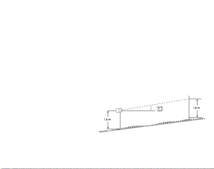
The left-hand scale gives the slope angle in degrees from the horizontal plane at eye
level. The right-hand scale gives the height of the point of sight from the same
horizontal eye level, and it is expressed in per cent of the horizontal distance.
The following example illustrates the procedure:
10
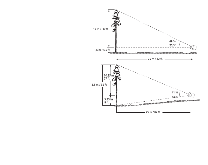
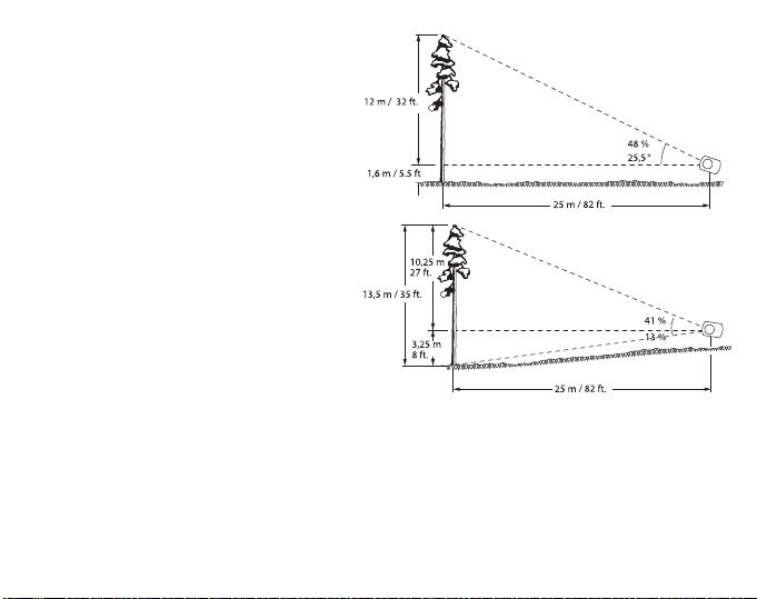
The task is to measure the
height of a tree at a distance of
25 m / 82 ft. on level ground.
The instrument is tilted so that
the hair line is seen against the
tree-top (apex). The reading
obtained will be 48 per cent (ca
25.5°). As the distance is 25 m /
82 ft. the height of the tree is 48
/ 100 x 25 m = ca. 12 m or
equally 48 / 100 x 25 m = ca. 12
m or equally 48 / 100 x 82 ft. =
ca. 39 ft. To this must be added
the eye’s height from the
ground, e.g. 1.6 m or 5 ½ ft.
Their sum is 13.6 m or 44 ½ ft,
the height of the tree.
In very exact measurements,
and particularly on sloping
ground two readings are taken,
one to the top, the other to the base of the trunk. When the trunk base is below eye
level the percentages obtained are added. The total height is the sum percentage of
the horizontal distance. For example, it the apex reading is 41 % and the ground
reading 13 %, the total height of the tree measured from a distance of 25 m / 82 ft. is
(41 + 13) / 100 x 25 m = 54 / 100 x 25 m = ca. 13.5 m or equally in feet (41 + 13) / 100
x 82 ft = 54 / 100 x 82 ft = ca. 44 ½ ft.
11
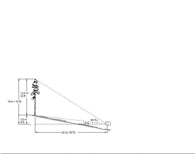
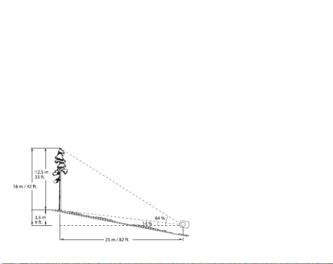
When the trunk base is above eye level, the base reading is subtracted from the apex
reading, and the total height is the difference percentage of the horizontal distance.
For example, if the apex reading is 65 % and the base reading 14 %, the total height
is (64 – 14) / 100 x 25 m = 50 / 10 0 x 25 m = 12.5 m or equally in feet (64 – 14) / 100
x 82 ft = 50 / 100 x 82 ft = 41 ft. When calculations are made mentally it is advisable to
use measuring distance of 50, 100 or 200 m / ft. for the sake of simplicity.
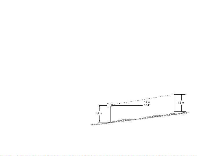
All readings of the percentage scale are based on the horizontal distance. This
means that if the distance on sloping terrain is measured along the ground an error is
introduced, and this must be corrected for accurate results. The error is insignificant
for most purposes at small ground slope angles but increases progressively as the
angle increases.
12
The trigonometrical correlation is
H = h x cos
α
Where H is the true or corrected height, h is the observed height and α (alpha) is the
ground slope angle. With the aid of the above equation the correction can also be
made in the distance. In this case h means the distance measured along the ground
and H is the horizontal distance sought. If the corrected distance is used no correction
in the height observed is needed. When calculating the horizontal distance by using
the ground distance and the slope, it must be pointed out that an error is introduced if
the slope is measured from eye level to the trunk base. Measuring the slope along the
ground would be cumbersome and inconvenient. No error is introduced, however,
when the slope angle is measured from eye level to sighting mark made or placed on
the trunk at eye level whereby the two lines of measurement become parallel.
The true angle of slope is 9 degrees.
The example shown in the following figure illustrates both methods of calculation.
Method 1. Measure the ground
distance. This is found to be
25 m / 82 ft. Then measure the
slope angle. This is 9 degrees.
Read percentages of top and
ground points. These are 29 and
23 per cent.
13

Calculate:
23
100
——— —
29
100
——— —
52
100
——— —=+
52
100
——— —
24 6m 12 8m,=,×
52
100
——— —
80 9ft 42ft=,×
Take 52 per cent of 25 m / 82 ft. This is 13 m / 42.6 ft. Multiply this by the cosine of
9 degrees.
0.987 x 13 m = 12.8 m or equally in feet 0.987 x 42.6 ft. = 42 ft.
Method 2. Multiply the ground distance by the slope angle cosine.
0.987 x 25 m = 24.6 m or equally in feet 0.987 x 82 ft. = 80.9 ft.
Add percentage readings as above and take the sum percentage of the corrected
distance.
or equally in feet
This example shows that a slope angle of 9 degrees causes a correction of only
2.3 per cent but when the slope angle is 35 degrees the correction means a reduction
of about 18 per cent in the observed height.
14

NOMOGRAPHICAL HEIGHT CORRECTION
When the nomogram is used, all correction calculation becomes unnecessary. Only a
ruler or some other convenient object with a straight edge is nee ded to obtain the
nomographical solution. The nomogram is used by placing the ruler so that its edge
intersects the angle scale on the left at the slope angle point and the observed height
scale (on the right) at the pertinent point. The corrected height (or distance) is read at
the point where the edge intersects the corrected height scale in the middle. When
using a measuring distance of 100 m / ft. along the ground the corr ection procedure
becomes very simple. No slope angle measurement is then necessary. One needs
only the reading of the top point and that of the ground point. Depending on the
situation their sum or difference gives the apparent height directly in feet. This is then
corrected as follows: First, find on the right-hand scale in the nomogram the point
indicating the apparent height. Secondly find on the left-hand double scale the point
indicating the ground point reading. Thirdly, connect these points. The corrected
reading will be found from the pertinent middle scale at the point of intersection. In
this procedure the slope angle can be neglected as the left-hand ground point scale
has been constructed so that slope angle and the average eye level height of 1.6 m /
5.5 ft. have been taken into account.
15

INSTRUMENT BODY COVER FOR SUUNTO KB-14 AND PM-5
The instrument body cover is suited to the following KB and PM models:
KB-14 (all models) and PM-5.
16

Suunto PM-5, PM-5/1520
GUIDE DE L’UTILISATEUR
FR

TABLE DES MATIÈRES
PM-5/1520 …………………………………………………………………………………………………. 4
ALTIMÈTRE OPTIQUE ………………………………………………………………………….. 4
MODE D’EMPLOI ………………………………………………………………………………….. 4
MESURE DES HAUTEURS ……………………………………………………………………. 5
MODE D’EMPLOI DU NOMOGRAMME …………………………………………………… 6
DÉTERMINATION DE LA DISTANCE DE BASE ………………………………………. 6
PM-5 …………………………………………………………………………………………………………. 8
CLINOMÈTRE À LECTURE OPTIQUE ……………………………………………………. 8
VERSIONS DE PM-5 DISPONIBLES ……………………………………………………….9
MODE D’EMPLOI ………………………………………………………………………………… 10
CORRECTION DE LA HAUTEUR NOMOGRAPHIQUE ……………………………. 15
PROTECTION DU CORPS DES KB-14 ET PM-5 DE SUUNTO ………………… 16
3

PM-5/1520
ALTIMÈTRE OPTIQUE
L’altimètre PM-5/1520 de Suunto est un instrument destiné à mesurer des hauteurs
et plus particulièrement des hauteurs d’arbres, avec précision et rapidité. Le corps de
l’instrument est en aluminium anodisé résistant à la corrosion. Le disque gradué
repose sur un palier spécial dans une capsule en plastique étanche et toutes les
parties mobiles sont immergées dans un liquide, ce qui permet au cadran de se
déplacer librement et de s’arrêter rapidement. Le liquide ne gèle pas, conserve
l’ensemble de ses propriétés d’amortissement dans des conditions de travail et
élimine les vibrations irritantes de la calamine.
MODE D’EMPLOI
En cas de mesure d’une hauteur à une distance de 15 ou 20 mètres, trois hauteurs
peuvent être lues directement sur l’échelle de l’altimètre. En cas de mesure d’une
hauteur à une distance de 30 ou 40 mètres, le chiffre obtenu doit être doublé.
L’altimètre de Suunto peut également être utilisé pour déterminer l’angle d’une pente.
Pour ce faire, il convient de visualiser la ligne de la pente à l’aide de l’échelle de
20 mètres à gauche de l’instrument. Le relevé obtenu perme ttant d’obtenir l’angle
peut être comparé aux chiffres indiqués dans le tableau de conversion situé à l’arrière
de l’instrument.
4
MESURE DES HAUTEURS
La mesure réelle de la hauteur de
l’arbre doit être réalisée depuis la
distance mesurée comme suit :
l’observateur vise la cime de l’arbre en
gardant les deux yeux ouverts. L’objet
observé, le réticule et l’échelle
apparaissent simultanément dans le
champ de vision de l’instrument. Dès
que le réticule coïncide avec la cime
de l’arbre, la hauteur de ce dernier
peut être lue (dans cet exemple, à
partir de l’échelle de 20 m à gauche
de l’instrument). La lecture obtenue
correspond à la hauteur de l’arbre
mesurée à hauteur des yeux de
l’observateur. La base de l’arbre n’est
pas observée. Si elle se trouve sous
la hauteur des yeux de l’observateur,
la hauteur réelle de l’arbre est
obtenue en cumulant les deux
relevés. Si elle se trouve au-dessus
de la hauteur des yeux de
l’observateur, la hauteur de l’arbre est
obtenue en calculant la différence
entre les deux relevés. En fait, dans le
5
dernier cas, la distance ne peut pas être mesurée horizontalement. Par conséquent,
pour obtenir le résultat exact, il convient de procéder comme suit : sur un sol plat, les
lectures supérieures de l’arbre suffisent généralement : il suffit d’ajouter la hauteur au
niveau des yeux de l’observateur (1,60 m dans ce cas), qui est déjà connue.
MODE D’EMPLOI DU NOMOGRAMME
Si, en raison d’un terrain irrégulier, la
distance ne peut pas être déterminée
horizontalement comme indiqué ci-dessus,
le nomogramme de la page 7 doit être
utilisé.
DÉTERMINATION DE LA DISTANCE DE BASE
Étant donné que cet instrument ne comporte pas de prisme, la distance de base, par
exemple 15 mètres, doit être mesurée à l’aide d’un ruban d’arpenteur. Prendre les
lectures du sommet et du pied et additionner ou soustraire ces valeurs pour obtenir la
hauteur apparente. Sur le nomogramme de la page 7, chercher la hauteur apparente
sur l’échelle de droite. Sur l´échelle double de gauche, chercher la lecture obtenue en
visant le pied de l´arbre. Noter que les lectures des gradients doivent être prises de
côtés différents de l’échelle. Relier ces deux points du nomogramme par une ligne
droite. L’échelle centrale du nomogramme indique désormais la hauteur réelle de
l’arbre.
6
Remarque importante
16
15
14
13
12
11
10
9
8
7
6
5
4
3
2
1
0
21
20
19
18
17
16
15
14
13
12
11
10
9
8
7
6
5
4
2
6
7
8
9
10
11
12
13
14
15
16
17
18
19
20
m
4
5
6
7
8
9
10
11
12
13
14
15
16
17
18
19
20
m
L-20
m
Terrain mountant
Lecture à la base
Hauteur corrigée
Hauteur apparente
Terrain déclinant
Les axes optiques des yeux de certaines
personnes ne sont pas parallèles. Ce
phénomène s’appelle hétérophorie. Il peut
varier avec le temps et dépend également
de plusieurs facteurs. Par conséquent,
afin de s´assurer que ce phénomène
n’affectera pas la précision des lectures, il
est conseillé à l’utilisateur de contrôler sa
vue, avant la lecture, en faisant le petit
test suivant : commencer par effectuer
une lecture en gardant les deux yeux
ouverts, puis fermer l’œil libre. Si les
lectures ne divergent pas
considérablement, c’est que les axes
optiques sont alignés, et les deux yeux
peuvent donc être tenus ouverts pour
prendre des lectures. Si les lectures
diffèrent, tenir l’autre œil fermé et viser à
mi-chemin en direction du côté du corps
de l´instrument, afin de créer une illusion
optique, grâce à laquelle le réticule se
prolonge au-delà du corps de l’instrument
et est visible contre l’objectif.
7
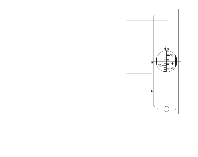
PM-5
Graduation
en % +/-
Graduation
en degrés +/-
Prolongement
du réticule dû
à l’illusion
optique
Graduation complémentaire en
degrés de la fenêtre latérale
CLINOMÈTRE À LECTURE OPTIQUE
Le CLINOMÈTRE de poche SUUNTO est solide, ce qui
permet de l’utiliser pour tout type de travail. Grâce à sa
lentille exempte de parallaxe intégrée au design, il
permet une lecture facile et rapide.
La visée et la lecture s’effectuent simultanément.
L’instrument ne comporte ni vis de fixation, ni niveau, ni
besoin de réglage.
En cas d’espace restreint, comme dans les travaux
géologiques et minéralogiques, les déclivités et autres
formations peuvent être déterminées en plaçant
l’instrument le long du contour ou de la surface de la
formation ; l’angle est ensuite lu directement à travers
la fenêtre latérale.
Caractéristiques de la construction
La structure est en aluminium léger résistant à la
corrosion.
Le disque gradué est soutenu par un ensemble de
paliers à rubis et toutes les pièces mobiles sont
immergées dans une capsule en plastique hermétique et très solide remplie de
liquide amortisseur. Le liquide amortit toutes les vibrations excessives de l’échelle et
permet un mouvement en douceur et sans à-coups du disque gradué.
Le matériau du conteneur n’est pas agressé par le soleil ou l’eau. Le liquide ne gèle
pas dans les conditions arctiques et ne s’évapore pas sous les tropiques.
8

Caractéristiques techniques
Poids : 120 g Dimensions : 74 x 52 x 15 mm. Les échelles optiques sont graduées en
degrés, de 0° à ±90° et de 0 % à ±150 %.
Une table de cosinus est imprimée au dos de l’instrument.
Résolution
Elle peut être lue directement selon une précision de 1 degré ou 1 %. Elle peut être
estimée avec une précision de 10 minutes ou env. 1/5 de 1 %, ce dernier chiffre
s’appliquant naturellement aux lectures autour de zéro.
VERSIONS DE PM-5 DISPONIBLES
Le PM-5/360 PC de base a été développé en plusieurs variantes dotées de
différentes combinaisons de graduation pour des usages spéciaux. Par conséquent,
une version comportant une graduation de ”nouveaux degrés” ou grades est
maintenant disponible. Ici, plutôt que d’observer la division normale en 360 degrés, le
cercle complet est divisé en 400 grades (g). La graduation en pourcentage est
normale. Le modèle concerné est le PM-5/400 PC.
9

MODE D’EMPLOI
Les mesures s’effectuent généralement à l’aide de l’œil droit. En raison des
différences d’acuité visuelle et des préférences personnelles, il est parfois plus facile
d’utiliser l’œil gauche. Il est de la plus haute importance de garder les deux yeux
ouverts. La main soutenant l’instrument ne doit pas gêner la vision de l’autre œil.
Tenir l’instrument devant l’œil qui effectue la lecture, de sorte que la graduation soit
lisible à travers l’optique et que la fenêtre latérale ronde soit orientée vers la gauche.
Orienter l’instrument vers l’objet en le soulevant ou en l’abaissant jusqu’à ce que le
réticule soit visible sur le point à mesurer. Parallèlement, lire la position du réticule sur
l’échelle pour obtenir la mesure. En raison de l’illusion optique, le réticule (pointeur en
croix) semble se prolonger au-delà du cadre et peut donc être observé facilement sur
le terrain ou l’objet.
La graduation à gauche indique l’angle de la pente en degrés depuis le plan
horizontal à la hauteur des yeux. La graduation de droite indique la hauteur de
l’objectif depuis la même hauteur horizontale des yeux et elle est exprimée en
pourcentage de la distance horizontale. L’exemple suivant illustre la procédure.
10
La tâche consiste à mesurer la
hauteur d’un arbre situé à une
distance de 25 m / 82 pi. sur un sol
plat. L’instrument est incliné, de
sorte que le réticule soit visible
contre la cime de l’arbre (sommet).
La lecture obtenue est 48 %
(environ 25,5°). Comme la distance
est de 25 m / 82 pi., la hauteur de
l’arbre est de 48 / 100 x 25 m = env.
12 m, soit 48 / 100 x 25 m = env. 12
m, soit 48 / 100 x 82 pi. = env. 39 pi.
À ce chiffre doit être ajoutée la
hauteur des yeux depuis le sol, par
ex. 1,6 m ou 5 pi.½. La somme de
ces chiffres est 13,6 m, soit 44 pi.
½, ce qui correspond à la hauteur
de l’arbre.
En cas de mesures très précises et
en particulier sur un sol en pente, deux relevés sont réalisés, le premier au sommet et
l’autre à la base du tronc. Lorsque la base du tronc se trouve sous la hauteur des
yeux, les pourcentages obtenus sont ajoutés. La hauteur totale correspond au
pourcentage total de la distance horizontale. Par exemple, si la lecture du sommet est
41 % et la lecture du sol 13 %, la hauteur totale de l’arbre mesurée à une distance de
25 m / 82 pi. est (41 + 13) / 100 x 25 m = 54 / 100 x 25 m = env. 13.5 m, soit (41 + 13)
/ 100 x 82 pi. = 54 / 100 x 82 pi. = env. 44 ½ pi.
11
Lorsque la base du tronc se situe au-dessus de la hauteur des yeux, la lecture de la
base est soustraite de la lecture du sommet et la hauteur totale correspond à la
différence en pourcentage de la distance horizontale.
Par exemple, si la lecture du sommet est 65 % et la lecture de la base 14 %, la
hauteur totale est (64 – 14) / 100 x 25 m = 50 / 100 x 25 m = 12,5 m, soit (64 – 14) /
100 x 82 pi. = 50 / 100 x 82 pi. = 41 pi. Pour des raisons de simplicité, lorsque les
calculs sont réalisés mentalement, il est conseillé d’utiliser une distance de 50, 100
ou 200 m / pi.
Tous les relevés sur l’échelle des pourcentages sont effectués à partir de la distance
horizontale. Cela signifie que si la distance d’un terrain en pente est mesurée au sol,
une erreur est insérée et doit être corrigée pour que les résultats soient corrects.
Cette erreur est peu importante dans la plupart des cas lorsque les angles sont
faibles mais elle augmente progressivement lorsque l’angle s’accentue.
12
La corrélation trigonométrique est la suivante :
H = h x cos
α
où H est la hauteur réelle ou corrigée, h la hauteur observée et α (alpha) l’angle de la
pente au sol. À l’aide de l’équation précédente, il est également possible de procéder
à la correction à distance. Dans ce cas, h correspond à la distance mesurée au sol et
H à la distance horizontale recherchée. Si la distance corrigée est utilisée, il n’est pas
nécessaire de corriger la hauteur observée. Lors du calcul de la distance horizontale
à l’aide de la distance au sol et de la pente, il convient de préciser qu’une erreur est
insérée si la pente est mesurée depuis la hauteur des yeux jusqu’à la base du tronc.
Il serait gênant et non pratique de mesurer la pente au sol. Toutefois, aucune erreur
n’est insérée lorsque l’angle de la pente est mesuré depuis la hauteur des yeux
jusqu’au repère indicateur réalisé ou placé sur le tronc à la hauteur des yeux, les
deux lignes de la mesure devenant parallèles. L’angle réel de la pente est de 9
degrés.
L’exemple indiqué sur la figure
suivante illustre les deux
méthodes de calcul.
1ère méthode : mesurer la
distance au sol. Elle est égale à
25 m / 82 pi. Ensuite, mesurer
l’angle de la pente. Il est de 9
degrés. Lire les pourcentages
des points situés au niveau de la
cime et du sol. Ils sont de 29 et
23 %.
13

Calculer :
23
100
——— —
29
100
——— —
52
100
——— —=+
52
100
——— —
24 6m 12 8m,=,×
52
100
——— —
80 9ft 42ft=,×
Prendre 52 % de 25 m / 82 pi. Cela correspond à 13 m / 42,6 pi. Multiplier ce chiffre
par le cosinus de 9 degrés.
0,987 x 13 m = 12,8 m, soit 0,987 x 42,6 pi. = 42 pi.
2ème méthode : multiplier la distance au sol par le cosinus de l’angle de la pente.
0,987 x 25 m = 24,6 m, soit 0,987 x 82 pi. = 80,9 pi.
Ajouter le relevé des pourcentages comme indiqué ci-dessus et prendre la somme
des pourcentages de la distance corrigée.
soit
Cet exemple indique qu’un angle de 9 degrés entraîne une correction de 2,3 %
seulement mais lorsque l’angle est de 35 degrés, la correction correspond à une
réduction d’environ 18 % de la hauteur observée.
14
Loading…
- Главная
- Поддержка
- Suunto PM-5
Здесь вы найдете руководства пользователя, учебные видеоролики, ответы на частые вопросы, статьи с инструкциями и подробные сведения о поддержке для Suunto PM-5.
Suunto PM-5
—
Популярные темы поддержки
Руководства пользователя
Руководства пользователя содержат комплексный обзор возможностей продуктов, инструкции по использованию, рекомендации по эксплуатации и хранению, а также технические характеристики.
Загрузить PDF
ЯРЛЫКИ ОСНОВНЫХ ТЕМ ПОДДЕРЖКИ
Обратитесь в службу поддержки
СВЯЖИТЕСЬ С НАМИ
Мы готовы ответить на ваши вопросы в живом чате круглосуточно с понедельника по пятницу. Служба поддержки работает без перерывов с 9:00 по центральноевропейскому времени (CET) до 9:00 CET следующего дня.
Более подробно см. здесь.
Инструкция по эксплуатации.
На гипсометре имеются шкалы, по которым можно прямо считывать высоту дерева в метрах при измерениях, происходящих с расстояния 15 или 20 м. При желании можно использовать расстояния 30 и 40 м, тогда отсчеты по измерителю следует умножить на два. Угол наклона местности можно при желании выяснить при взятии отсчета по направлению местности по левой 20-метровой шкале и при преобразовании его в градусы с помощью переводной таблицы, находящейся на одной из сторон высотомера.
A. Измерение расстояния
Расстояние можно измерить обычной мерной лентой.
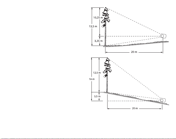
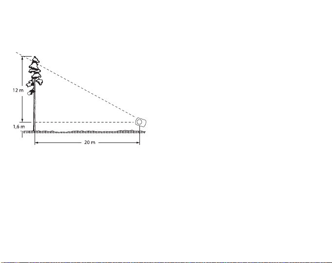
Б. Измерение высоты
Собственно измерение производится согласно измеренному расстоянию по пункту А следующим образом: производят наводку при обоих открытых глазах, как на обложке этой брошюрки, на вершину дерева. При этом в зоне видимости одновременно просматривается измеряемый объект, волосная линия и шкала. При нахождении волосной линии на вершине берут на шкале отсчет высоты дерева. (В этом примере по левосторонней 20-метровой шкале). Полученный так отсчет вершины представляет собой высоту дерева от уровня глаза до вершины. Также берут отсчет основания. Если основание дерева находится ниже уровня глаза, то высота дерева есть сумма так полученных отсчетов. Если же основание дерева находится выше уровня глаза, то высота дерева есть разность отсчетов. Часто на ровной местности обходятся применением лишь вершинного отсчета, тогда высоту глаз измеряющего прибавляют к отсчету вершины. B. Использование номограммы Если из-за разности отметок местности не представилось возможным измерить в горизонтальной плоскости расстояние, описанное в пункте А, то этим вызывается небольшая ошибка, величина которой зависит от величины угла покатости местности. Эту ошибку можно исправить с помощью номограммы тогда вместо угла покатости используют отсчет основания, т.е. отсчет по измерителю при наводке на основании дерева.. Внимание: при измерении расстояния мерной лентой следует применять номограмму 1520, а при измерении расстояния призмой следует применять номограмму 1520 Р.
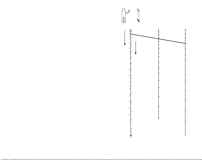
Номограмму применяют следующим образом:
I. Выбирают из четырех номограмм карточки ту, которая соответствует расстоянию измерения и высоте дерева.
II. Измеряют кажущуюся высоту дерева способом, описанным выше в пункте Б. По шкале номограммы, находящейся на правом краю, выбирают точку (например 17 м), соответствующую кажущейся высоте.
III По левосторонней шкале номограммы выбирают точку, которая соответствует отсчету основания.Отсчеты взятые наискось по нисходящей и наискось по восходящей находятся на разных сторонах шкальной линии. Например, измеряли по восходящей и получили отсчет основания 2 м.
IV. Выбранные в пунктах II и III точки соединяют прямой линией. Точка пересечения на средней шкале номограммы выражает действительную высоту дерева. Например, она равна 16,5 м.
ВАЖНО ЗНАТЬ!
У некоторых лиц оптические оси глаз непараллельные. Это явление называют гетерофорией. Явление может с течением времени изменяться и может быть зависимо от многих факторов. Чтобы быть уверенным в том, что вышеупомянутое явление не влияет на точность отсчетов, есть повод для того, чтобы пользующийся инструментом до взятия отсчетов обследовал свои глаза с помощью следующего небольшого опыта: Возьмите вначале отсчет при обоих открытых глазах. Возьмите затем отсчет при закрытом свободном глазе. Если отсчеты существенно не различаются один от другого, то отклонение осей глаз не является многозначительным, и оба глаза можно держать открытыми при взятии отсчета.
Если в отсчетах есть разница,то один глаз следует держать закрытым и делать наводку наполовину мимо корпуса инструмента, используя оптическую иллюзию, когда волосная линия продолжается за край корпуса инструмента и видится на фоне объекта.