
| Название | Русский | English |
|---|---|---|
| RX-V420 OWNER’S MANUAL | — |
[2.7MB] |
| RX-V420RDS OWNER’S MANUAL | — |
[1.5MB] |
| RX-V430 OWNER’S MANUAL | — |
[1.3MB] |
| RX-V430RDS OWNER’S MANUAL | — |
[1.1MB] |
| RX-V440 Owner’s Manual | — |
[2.5MB] |
| RX-V450 Owner’s Manual | — |
[2.8MB] |
| RX-V457 Owner’s Manual | — |
[1.6MB] |
| RX-V459 Owner’s Manual | — |
[2.1MB] |
| RX-V4600 Owner’s Manual | — |
[2.1MB] |
| RX-V461 Owner’s Manual | — |
[5.7MB] |
| RX-V463 OWNER’S MANUAL | — |
[4.8MB] |
| RX-V463 Owner’s Manual | — |
[3.9MB] |
| RX-V463 ИНСТРУКЦИЯ ПО ЭКСПЛУАТАЦИИ |
[4.8MB] |
[4.8MB] |
| RX-V465 OWNER’S MANUAL | — |
[2.3MB] |
| RX-V465 ИНСТРУКЦИЯ ПО ЭКСПЛУАТАЦИИ |
[2.3MB] |
[2.3MB] |
| RX-V467 Owner’s Manual | — |
[7.1MB] |
| RX-V467 Quick Reference Guide | — |
[1.1MB] |
| RX-V467 Краткое руководство |
[1.2MB] |
[1.1MB] |
| RX-V467 Руководство пользователя |
[7.3MB] |
[7.1MB] |
| RX-V470 OWNER’S MANUAL | — |
[366KB] |
| RX-V471 Easy Setup Guide for North America, Europe and Oceania | — |
[1.6MB] |
| RX-V471 Owner’s Manual for North America, Europe and Oceania | — |
[15.9MB] |
| RX-V473 Firmware Update Version 1.16_Installation_Manual | — |
[296KB] |
| RX-V473/RX-V573/HTR-4065/HTR-5065 Firmware Update_Installation_Manual | — |
[585KB] |
| RX-V475/RX-V575/HTR-4066/HTR-5066 Firmware Update Installation Manual | — |
[693KB] |
| RX-V477 Firmware Update Installation Manual | — |
[268KB] |
| RX-V480 OWNER’S MANUAL | — |
[276KB] |
| RX-V481 / RX-V481D / HTR-4069 firmware update installation manual | — |
[713KB] |
| RX-V490 OWNER’S MANUAL | — |
[407KB] |
| RX-V492 OWNER’S MANUAL | — |
[588KB] |

RX-V459
AV Receiver
Ampli-tuner audio-vidéo
G
OWNER’S MANUAL
MODE D’EMPLOI
BEDIENUNGSANLEITUNG
BRUKSANVISNING
GEBRUIKSAANWIJZING
ИНСТРУКЦИЯ ПО ЭКСПЛУАТАЦИИ
CAUTION: READ THIS BEFORE OPERATING YOUR UNIT.
CAUTION: READ THIS BEFORE OPERATING YOUR UNIT.
1 To assure the finest performance, please read this manual
carefully. Keep it in a safe place for future reference.
2 Install this sound system in a well ventilated, cool, dry, clean
place – away from direct sunlight, heat sources, vibration,
dust, moisture, and/or cold. Allow ventilation space of at
least 30 cm on the top, 20 cm on the left and right, and 20
cm on the back of this unit.
3 Locate this unit away from other electrical appliances,
motors, or transformers to avoid humming sounds.
4 Do not expose this unit to sudden temperature changes from
cold to hot, and do not locate this unit in a environment with
high humidity (i.e. a room with a humidifier) to prevent
condensation inside this unit, which may cause an electrical
shock, fire, damage to this unit, and/or personal injury.
5 Avoid installing this unit where foreign object may fall onto
this unit and/or this unit may be exposed to liquid dripping
or splashing. On the top of this unit, do not place:
– other components, as they may cause damage and/or
discoloration on the surface of this unit.
– burning objects (i.e. candles), as they may cause fire,
damage to this unit, and/or personal injury.
– containers with liquid in them, as they may fall and
liquid may cause electrical shock to the user and/or
damage to this unit.
6 Do not cover this unit with a newspaper, tablecloth, curtain,
etc. in order not to obstruct heat radiation. If the temperature
inside this unit rises, it may cause fire, damage to this unit,
and/or personal injury.
7 Do not plug in this unit to a wall outlet until all connections
are complete.
8 Do not operate this unit upside-down. It may overheat,
possibly causing damage.
9 Do not use force on switches, knobs and/or cords.
10 When disconnecting the power cable from the wall outlet,
grasp the plug; do not pull the cord.
11 Do not clean this unit with chemical solvents; this might
damage the finish. Use a clean, dry cloth.
12 Only voltage specified on this unit must be used. Using this
unit with a higher voltage than specified is dangerous and
may cause fire, damage to this unit, and/or personal injury.
YAMAHA will not be held responsible for any damage
resulting from use of this unit with a voltage other than
specified.
13 To prevent damage by lightning, keep the power cable and
outdoor antennas disconnected from a wall outlet or this unit
during a lightning storm.
14 Do not attempt to modify or fix this unit. Contact qualified
YAMAHA service personnel when any service is needed.
The cabinet should never be opened for any reasons.
15 When not planning to use this unit for long periods of time
(i.e. vacation), disconnect the AC power plug from the wall
outlet.
16 Install this unit near the AC wall outlet where the power
cable plug can be reached easily.
17 Be sure to read the “TROUBLESHOOTING” section on
common operating errors before concluding that this unit is
faulty.
18 Before moving this unit, press STANDBY/ON to set this
unit in the standby mode, and then disconnect the power
cable from the AC wall outlet.
19 VOLTAGE SELECTOR (Asia and General models only)
The VOLTAGE SELECTOR on the rear panel of this unit
must be set for your local main voltage BEFORE plugging
into the AC wall outlet. Voltages are:
Asia model ………………………. 220/230–240 V AC, 50/60 Hz
General model …….. 110/120/220/230–240 V AC, 50/60 Hz
WARNING
TO REDUCE THE RISK OF FIRE OR ELECTRIC
SHOCK, DO NOT EXPOSE THIS UNIT TO RAIN
OR MOISTURE.
This unit is not disconnected from the AC power
source as long as it is connected to the wall outlet, even
if this unit itself is turned off. In this state, this unit is
designed to consume a very small quantity of power.
■ For U.K. customers
If the socket outlets in the home are not suitable for the
plug supplied with this appliance, it should be cut off and
an appropriate 3 pin plug fitted. For details, refer to the
instructions described below.
Note
The plug severed from the mains lead must be destroyed, as a
plug with bared flexible cord is hazardous if engaged in a live
socket outlet.
■ Special Instructions for U.K. Model
IMPORTANT
THE WIRES IN MAINS LEAD ARE COLOURED IN
ACCORDANCE WITH THE FOLLOWING CODE:
Blue: NEUTRAL
Brown: LIVE
As the colours of the wires in the mains lead of this
apparatus may not correspond with the coloured
markings identifying the terminals in your plug,
proceed as follows:
The wire which is coloured BLUE must be connected
to the terminal which is marked with the letter N or
coloured BLACK. The wire which is coloured
BROWN must be connected to the terminal which is
marked with the letter L or coloured RED.
Making sure that neither core is connected to the earth
terminal of the three pin plug.

CONTENTS
INTRODUCTION
FEATURES……………………………………………………. 2
GETTING STARTED…………………………………….. 3
Supplied accessories ………………………………………….. 3
Installing batteries in the remote control ………………. 3
CONTROLS AND FUNCTIONS ……………………. 4
Front panel ……………………………………………………….. 4
Remote control………………………………………………….. 6
Front panel display ……………………………………………. 8
Rear panel ………………………………………………………. 10
PREPARATION
CONNECTIONS ………………………………………….. 11
Placing speakers………………………………………………. 11
Connecting speakers ………………………………………… 12
Information on jacks and cable plugs …………………. 15
Audio and video signal flow……………………………… 16
Connecting a TV……………………………………………… 17
Connecting a DVD player,
a DVD recorder, a VCR or an STB ………………… 18
Connecting a CD player,
an MD player or a tape deck………………………….. 20
Connecting a multi-format player
or an external decoder ………………………………….. 21
Connecting a game console,
a video camera or a portable audio player……….. 21
Connecting the FM and AM antennas ………………… 22
Connecting the power cable………………………………. 23
Setting the speaker impedance…………………………… 24
Turning on this unit
and setting it to the standby mode………………….. 25
BASIC SETUP ……………………………………………… 26
BASIC OPERATION
PLAYBACK…………………………………………………. 29
USING OTHER FEATURES………………………… 31
Using SILENT CINEMA …………………………………. 31
Muting the audio output……………………………………. 31
Selecting the night listening mode……………………… 31
Selecting the input mode ………………………………….. 32
Using the sleep timer ……………………………………….. 33
Adjusting the speaker level……………………………….. 34
Selecting the Compressed Music
Enhancer mode ……………………………………………. 35
Selecting the MULTI CH INPUT component……… 36
Enjoying multi-channel sources
in 2-channel stereo……………………………………….. 36
Enjoying unprocessed input sources…………………… 36
Enjoying pure hi-fi stereo sound………………………… 37
Displaying the input source information …………….. 37
Playing video sources in the background ……………. 38
ENJOYING SURROUND SOUND …………………39
Enjoying multi-channel sources in surround ……….. 39
Enjoying 2-channel sources in surround……………… 40
Using Virtual CINEMA DSP ……………………………. 41
RECORDING………………………………………………..42
FM/AM TUNING…………………………………………..43
Automatic tuning …………………………………………….. 43
Manual tuning…………………………………………………. 44
Automatic preset tuning……………………………………. 45
Manual preset tuning ……………………………………….. 46
Selecting preset stations……………………………………. 47
Exchanging preset stations ……………………………….. 48
RADIO DATA SYSTEM TUNING
(U.K. AND EUROPE MODELS ONLY)……..50
Selecting the Radio Data System program ………….. 50
Using the Radio Data System station network …….. 51
Displaying the Radio Data System information …… 52
SOUND FIELD PROGRAMS
SOUND FIELD PROGRAMS ………………………..54
Selecting sound field programs …………………………. 54
Sound field program descriptions ………………………. 55
Changing sound field parameter settings…………….. 57
Sound field program speaker layouts …………………. 63
ADVANCED OPERATION
SET MENU ……………………………………………………66
Using SET MENU…………………………………………… 68
1 SOUND MENU……………………………………………. 70
2 INPUT MENU……………………………………………… 73
3 OPTION MENU…………………………………………… 75
ADVANCED SETUP ……………………………………..76
REMOTE CONTROL FEATURES ……………….78
Controlling this unit, a TV,
or other components …………………………………….. 78
Setting remote control codes …………………………….. 80
RESETTING THE SYSTEM………………………….81
ADDITIONAL INFORMATION
TROUBLESHOOTING …………………………………82
GLOSSARY…………………………………………………..86
Audio information …………………………………………… 86
Video information……………………………………………. 87
Sound field program information ………………………. 88
SPECIFICATIONS………………………………………..89
PREPARATIONINTRODUCTION
OPERATION
BASIC
SOUND FIELD
PROGRAMS
OPERATION
ADVANCED
INFORMATION
ADDITIONAL
English
1

FEATURES
FEATURES
Built-in 6-channel power amplifier
◆ Minimum RMS output power
(0.06% THD, 20 Hz to 20 kHz, 8 Ω)
Radio Data System
(U.K. and Europe models only)
◆ Radio Data System tuning capability
Front: 90 W + 90 W
Center: 90 W
Surround: 90 W + 90 W
Surround back: 90 W
Other features
◆ 192-kHz/24-bit D/A converter
◆ 6 additional input jacks for discrete multi-channel input
◆ S-video signal input/output capability
Sound field features
◆ Proprietary YAMAHA technology for the creation of
sound fields
◆ Dolby Digital/Dolby Digital EX decoder
◆ DTS/DTS-ES Matrix 6.1, Discrete 6.1, DTS Neo:6,
DTS 96/24 decoder
◆ Dolby Pro Logic/Dolby Pro Logic II/
Dolby Pro Logic IIx decoder
◆ Virtual CINEMA DSP
◆ SILENT CINEMA
™
Sophisticated AM/FM tuner
◆ 40-station random and direct preset tuning
◆ Component video input/output capability
(3 COMPONENT VIDEO INs and 1 MONITOR
OUT)
◆ Optical and coaxial digital audio signal jacks
◆ Sleep timer
◆ Cinema and music night listening modes
◆ Remote control with preset remote control codes
◆ PORTABLE mini analog input jack on the front panel
for a portable audio player
◆ Compressed Music Enhancer mode to improve the
sound quality of compression artifacts (such as the
MP3 format) to that of a high-quality stereo
◆ Automatic preset tuning
◆ Preset station shifting capability (preset editing)
Notes
• y indicates a tip for your operation.
• Some operations can be performed by using either the buttons on the front panel or the ones on the remote control. In case the button
names differ between the front panel and the remote control, the button name on the remote control is given in parentheses.
• This manual is printed prior to production. Design and specifications are subject to change in part as a result of improvements, etc. In
case of differences between the manual and product, the product has priority.
Manufactured under license from Dolby Laboratories.
“Dolby”, “Pro Logic”, and the double-D symbol are trademarks
of Dolby Laboratories.
Manufactured under license from Digital Theater Systems, Inc.
“DTS”, “DTS-ES”, “NEO:6”, and “DTS 96/24” are trademarks
of Digital Theater Systems, Inc. Copyright 1996, 2003 Digital
Theater Systems, Inc. All right reserved.
2
“SILENT CINEMA” is a trademark of YAMAHA
CORPORATION.
GETTING STARTED
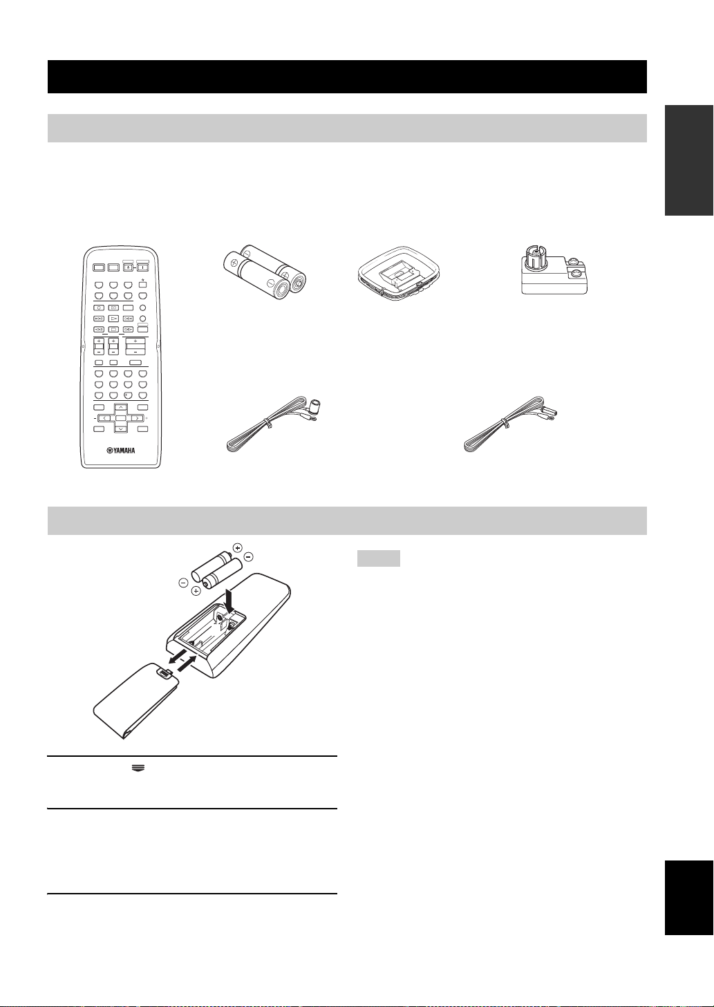
Supplied accessories
Check that you received all of the following parts.
GETTING STARTED
INTRODUCTION
Remote control Batteries (2)
(AA, R6, UM-3)
POWER POWER
POWER POWER
STANDBY
STANDBY
POWER
POWER
AVTV
AVTV
CD
MD/CD-R
TUNER
CD
MD/CD-R
TUNER
V-AUXDVD
VCR
DTV/CBL
V-AUXDVD
VCR
DTV/CBL
MULTI CH IN
MULTI CH IN
REC
REC
CODE SET
CODE SET
DISC SKIP
DISC SKIP
FREQ/TEXT EON
FREQ/TEXT EON
MODE PTY SEEK
MODE PTY SEEK
TV VOL TV CH
TV VOL TV CH
TV MUTE TV INPUT
TV MUTE TV INPUT
STEREO
STEREO
SPEAKERS
SPEAKERS
LEVEL
LEVEL
BAND
BAND
DAB MEMORY
DAB MEMORY
START
START
VOLUME
VOLUME
SELECT
SELECT
NIGHT
ENHANCER
NIGHT
ENHANCER
ENTER
ENTER
A/B/C/D/E A/B/C/D/E
A/B/C/D/E A/B/C/D/E
PRESET/CH
PRESET/CH
SLEEP
SLEEP
AMP
AMP
MUTE
MUTE
MOVIEENTERTAINMUSIC
MOVIEENTERTAINMUSIC
4321
4321
DIRECT ST.EXTD SUR.STANDARD
DIRECT ST.EXTD SUR.STANDARD
81070965
81070965
STRAIGHT
STRAIGHT
ENT.
ENT.
SET MENU
SET MENU
MENUTITLE
MENUTITLE
SRCH MODE
SRCH MODE
DISPLAYRETURN
DISPLAYRETURN
(U.S.A., Canada, China, Asia and General
Indoor FM antenna
models)
Installing batteries in the remote control
2
1
3
1 Press the part and slide the battery
compartment cover off.
2 Insert the two supplied batteries (AA, R6,
UM-3) according to the polarity markings
(+ and –) on the inside of the battery
compartment.
AM loop antenna
75-ohm/300-ohm
antenna adapter
(U.K. model only)
Indoor FM antenna
(U.K., Europe, Australia and Korea models)
Notes
• Change all of the batteries if you notice a decrease in the
operation range of the remote control.
• Do not use an old battery together with a new one.
• Do not use different types of batteries (such as alkaline and
manganese batteries) together. Read the packaging carefully as
these different types of batteries may have the same shape and
color.
• If the batteries have leaked, dispose of them immediately. Avoid
touching the leaked material or letting it come into contact with
clothing, etc. Clean the battery compartment thoroughly before
installing new batteries.
• Do not throw away batteries with general house waste; dispose
of them correctly in accordance with your local regulations.
• If the remote control is without batteries for more than
2 minutes, or if exhausted batteries remain in the remote
control, the contents of the memory may be cleared. When the
memory is cleared, insert new batteries, set up the remote
control code and program any acquired functions that may have
been cleared.
English
3 Slide the cover back until it snaps into place.
3
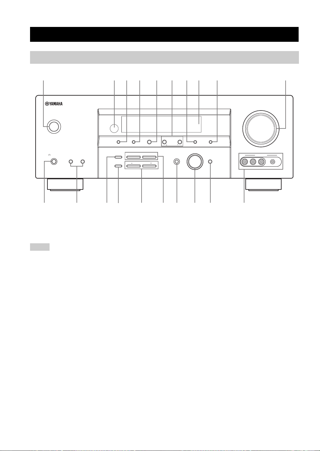
CONTROLS AND FUNCTIONS
Front panel
CONTROLS AND FUNCTIONS
214356897
STANDBY
/ON
A/B/C/D/E
STRAIGHT
EFFECT
EDIT
FM/AM
NEXT
l PROGRAM h
BASS/TREBLE
PRESET/TUNING
PHONES
SILENT CINEMA
A
SPEAKERS
B
BA
TONE CONTROL
CF
1 STANDBY/ON
Turns on this unit or set it to the standby mode
(see page 25).
Notes
• In the standby mode, this unit consumes a small amount of
power in order to receive infrared signals from the remote
control.
• When you turn on this unit, there will be a 4 to 5-second delay
before this unit can reproduce sound.
2 Remote control sensor
Receives signals from the remote control (see page 7).
3 PRESET/TUNING, EDIT
• Switches the function of PRESET/TUNING l / h
between selecting preset station numbers and selecting the
tuning frequency.
• Edits the assignments of preset stations (see page 48).
4 FM/AM
Switches the reception band between FM and AM when
“TUNER” is selected as the input source (see page 43).
0
VOLUME
l
PRESET/TUNING
h
LEVEL
INPUT MODE
GHIED
5 A/B/C/D/E, NEXT
• Selects one of the 5 preset station groups (A to E) when
“TUNER” is selected as the input source (see page 43).
• Selects the speaker channel whose output level you
want to adjust when “TUNER” is not selected as the
input source (see page 34).
6 PRESET/TUNING l / h, LEVEL +/– buttons
• Selects one of the 8 preset station numbers (1 to 
when “TUNER” is selected as the input source. The
colon (:) is displayed in the front panel display (see
page 47).
• Selects the tuning frequency when “TUNER” is
selected as the input source. The colon (:) is not
displayed in the front panel display (see page 44).
• Adjusts the level of the speaker channel selected using
NEXT when “TUNER” is not selected as the input
source (see page 34).
7 MEMORY (MAN’L/AUTO FM)
Stores a preset station in the memory. Hold down this
button for more than 3 seconds to start automatic preset
tuning (see page 45).
MEMORY
MAN’L/AUTO FM
INPUT
TUNING MODE
AUTO/MAN’L
MULTI CH
INPUT
VIDEO AUX
VIDEO PORTABLEL AUDIO R
J
4

CONTROLS AND FUNCTIONS
8 Front panel display
Shows information about the operational status of this unit
(see page 8).
9 TUNING MODE (AUTO/MAN’L)
Switches between automatic tuning (the AUTO indicator
is turned on) and manual tuning (the AUTO indicator is
turned off) (see page 43).
0 VOLUME
Controls the output level of all audio channels.
y
This does not affect the AUDIO OUT (REC) level.
A PHONES (SILENT CINEMA) jack
Outputs audio signals for private listening with
headphones (see page 31).
Notes
• When you connect headphones, no signals are output at the
SUBWOOFER OUTPUT jack or the speaker terminals.
• All Dolby Digital and DTS audio signals are mixed down to the
left and right headphone channels.
B SPEAKERS A/B buttons
Turns on or off the set of front speakers connected to the A
and/or B terminals on the rear panel each time the
corresponding button is pressed.
C STRAIGHT (EFFECT)
Turns the sound field programs off or on. When
“STRAIGHT” is selected, 2-channel or multi-channel
input signals are output directly from their respective
speakers without effect processing (see page 36).
I MULTI CH INPUT
Selects the input source connected to the MULTI CH
INPUT jacks (see page 36).
INTRODUCTION
Note
The input source connected to the MULTI CH INPUT jacks takes
priority over the source selected with the INPUT selector on the
front panel (or the input selector buttons on the remote control).
J VIDEO AUX jacks
Input audio and video signals from a portable external
source such as a game console, a video camera or a
portable audio player (see page 21).
y
To reproduce the source signals input at these jacks, select
“V-AUX” as the input source.
Note
The audio signals input at the PORTABLE mini jack take priority
over the ones input at the AUDIO L/R jacks.
D TONE CONTROL
Selects “BASS” or “TREBLE” to adjust the total balance
of the front left and right speakers in conjunction with
BASS/TREBLE +/– buttons (see page 30).
E BASS/TREBLE +/– button
Adjusts the bass/treble balance of the front left and right
speakers in conjunction with TONE CONTROL (see
page 30).
F PROGRAM l / h buttons
Selects sound field programs (see page 54).
G INPUT MODE
Selects either digital or analog input signals exclusively or
sets this unit to automatically detect the type of input
signals and select the corresponding input signals when
one component is connected via both digital and analog
connections (see page 32).
H INPUT selector
Selects the desired input source.
English
5
CONTROLS AND FUNCTIONS
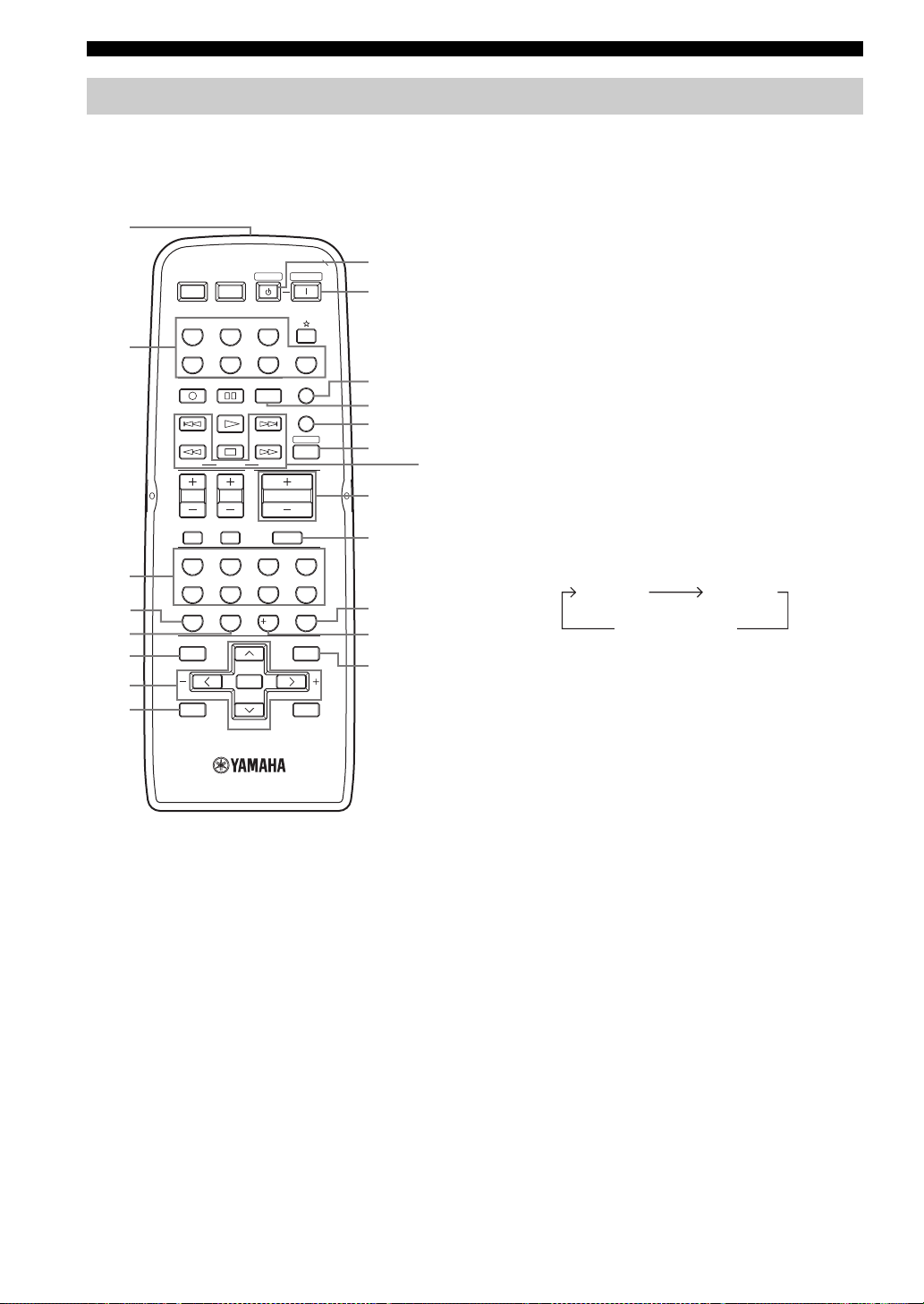
Remote control
This section describes the function of each control on the
remote control used to control this unit. To operate other
components, see “REMOTE CONTROL FEATURES” on
page 78.
1
9
0
A
B
C
D
J
E
F
G
H
I
2
3
4
5
6
7
8
POWER POWER
AVTV
CD
MD/CD-R
DTV/CBL
REC
DISC SKIP
FREQ/TEXT EON
MODE PTY SEEK
TV VOL TV CH
TV MUTE TV INPUT
STEREO
SELECT
65
ENHANCER
SPEAKERS
09
LEVEL
BAND
DAB MEMORY
ENTER
A/B/C/D/E A/B/C/D/E
PRESET/CH
STANDBY
TUNER
DVR
CODE SET
START
VOLUME
7
NIGHT
10
MUTE
POWER
V-AU XDVD
MULTI CH IN
SLEEP
AMP
MOVIEENTERTAINMUSIC
4321
DIRECT ST.EXTD SUR.STANDARD
8
STRAIGHT
ENT.
SET MENU
MENUTITLE
SRCH MODE
DISPLAYRETURN
■ Controlling this unit
Press AMP to control this unit.
1 Infrared signal transmitter
Outputs infrared control signals. Aim the transmitter at the
component you want to operate (see page 7).
2 Input selector buttons
Select the input source.
3 Sound field program selector buttons
Select sound field programs (see page 54).
– Use SELECT to play back 2-channel sources in
surround (see page 40).
– Use EXTD SUR. to switch between 5.1 and 6.1-
channel playback of multi-channel sources (see
page 39).
– Use DIRECT ST. to play back 2-channel sources in
hi-fi stereo sound (see page 37).
4 SPEAKERS
Turns on or off the set of front speakers connected to the
FRONT A and/or B terminals on the rear panel. Press this
button repeatedly to toggle as follows:
A on B on
A and B off
5 ENHANCER
Turns on or off the Compressed Music Enhancer mode
(see page 35).
6 LEVEL
Selects the speaker channel to be adjusted (see page 34).
7 Cursor buttons u / d / j / i, ENTER
Select and adjust the sound field program parameters or
the “SET MENU” parameters.
8 RETURN
Returns to the previous menu level when adjusting the
“SET MENU” parameters.
9 STANDBY
Sets this unit to the standby mode (see page 25).
0 POWER
Turns on this unit (see page 25).
6
CONTROLS AND FUNCTIONS
A MULTI CH IN
Selects the component connected to the MULTI CH
INPUT jacks as the input source when using an external
decoder, etc. (see page 36).
B CODE SET
Use to set up remote control codes (see page 80).
C SLEEP
Sets the sleep timer (see page 33).
D AMP
Sets the remote control to the operation mode of this unit.
E VOLUME +/–
Controls the output level of all audio channels.
Note
This does not affect the AUDIO OUT (REC) level.
F MUTE
Mutes the audio output. Press again to restore the audio
output to the previous volume level (see page 31).
G STRAIGHT
Turns the sound field programs off or on. When
“STRAIGHT” is selected, 2-channel or multi-channel
input signals are output directly from their respective
speakers without effect processing (see page 36).
H NIGHT
Turns on or off the night listening modes (see page 31).
I SET MENU
Enters “SET MENU” (see page 68).
J Radio Data System tuning buttons
(U.K. and Europe models only)
FREQ/TEXT
Switches the Radio Data System display between the
PS mode, PTY mode, RT mode, CT mode (if the
station offers the corresponding data services) and the
frequency display (see page 52).
PTY SEEK MODE
Sets this unit to the PTY SEEK mode (see page 50).
PTY SEEK START
Starts searching for a station once the desired program
type is selected in the PTY SEEK mode (see page 51).
EON
Selects a program type (NEWS, AFFAIRS, INFO, or
SPORT) for automatic tuning (see page 52).
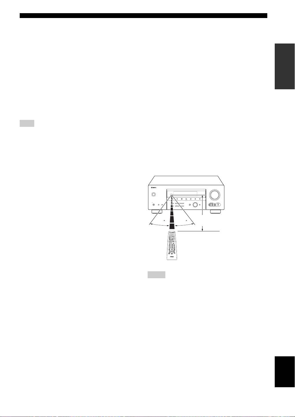
■ Using the remote control
The remote control transmits a directional infrared ray.
Be sure to aim the remote control directly at the remote
control sensor on the main unit during operation.
STANDBY
/ON
PHONES
SPEAKERS
SILENT CINEMA
FM/AM
PRESET/TUNING
A/B/C/D/E
l
PRESET/TUNING/CH
h
EDIT
l PROGRAM h
STRAIGHT
BA
EFFECT
TONE CONTROL
MEMORY
INPUT
INPUT MODE
BASS/TREBLE
Approximately 6 m (20 ft)
30 30
VOLUME
TUNING MODE
AUTO/MAN’LMAN’L/AUTO FMLEVELNEXT
VIDEO AUX
MULTI CH
INPUT
VIDEO PORTABLEL AUDIO R
INTRODUCTION
■ Controlling the TUNER functions
Press TUNER to control the TUNER functions.
3 Numeric buttons
Use numbers 1 through 8 to select preset stations.
6 BAND
Switches the reception band between FM and AM
(see page 43).
7 A/B/C/D/E j / i, PRESET/CH u / d
Press PRESET/CH u / d to select a preset station group
(A to E) and A/B/C/D/E j / i to select a preset station
number (1 to (see page 47).
Notes
• Do not spill water or other liquids on the remote control.
• Do not drop the remote control.
• Do not leave or store the remote control in the following types
of conditions:
– places of high humidity, such as near a bath
– places of high temperatures, such as near a heater or stove
– places of extremely low temperatures
– dusty places
English
7
CONTROLS AND FUNCTIONS
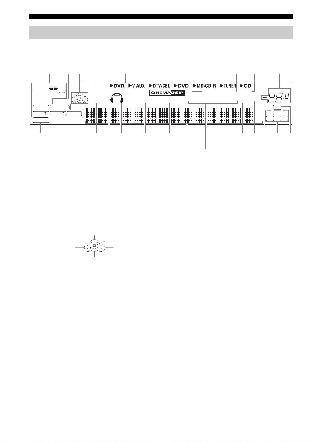
Front panel display
96
24
ENHANCER
q
DIGITAL
q PL
2
q PL
E
SILENT CINEMA
SP
A B
NIGHTSTANDARD
HiFi DSP
VIRTUAL
DGFHI JLKNM
8 AUTO indicator
Lights up when this unit is in the automatic tuning mode
(see page 43).
9 TUNED indicator
Lights up when this unit is tuned into a station
(see page 43).
0 STEREO indicator
Lights up when this unit is receiving a strong signal for an
134567 A
t
MATRIX DISCRETE
q EX
q PL x
PCM
C
1 Decoder indicators
The respective indicator lights up when any of the
decoders of this unit function.
2 ENHANCER indicator
Lights up when the Compressed Music Enhancer mode is
turned on (see page 35).
3 Sound field indicators
Light up to indicate the active DSP sound fields.
908B
TUNED
AUTO
PTYPTY
PSHOLD RT
(U.K. and Europe models only)
O
STEREO
EON
CT
MEMORY
SLEEP
FM stereo broadcast while the AUTO indicator is lit
(see page 43).
A MEMORY indicator
Flashes to show that a station can be stored (see page 45).
B VOLUME level indicator
Surround left
DSP sound field
Surround back DSP sound field
Presence DSP sound field
Listening position
Surround right
DSP sound field
Indicates the current volume level.
MUTE
ft
mS
dB
VOLUME
96/24
LFE
LCR
SL SB SR
dB
4 VIRTUAL indicator
Lights up when Virtual CINEMA DSP is active (see
page 41).
5 Input source indicators
The corresponding cursor lights up to show the currently
selected input source.
6 SILENT CINEMA indicator
Lights up when headphones are connected and a sound
field program is selected (see page 31).
7 CINEMA DSP indicator
Lights up when you select a CINEMA DSP sound field
program (see page 55).
8
C PCM indicator
Lights up when this unit is reproducing PCM (Pulse Code
Modulation) digital audio signals.
D STANDARD indicator
Lights up when the “SUR. STANDARD” or
“SUR. ENHANCED” programs are selected (see
page 40).
E SP A B indicators
Light up according to the set of front speakers selected.

F Headphones indicator
Lights up when headphones are connected (see page 31).
G NIGHT indicator
Lights up when you select a night listening mode
(see page 31).
H HiFi DSP indicator
Lights up when you select a HiFi DSP sound field
program (see page 55).
I Multi-information display
Shows the name of the current sound field program and
other information when adjusting or changing settings.
J SLEEP indicator
Lights up while the sleep timer is on (see page 33).
K MUTE indicator
Flashes while the MUTE function is on (see page 31).
L 96/24 indicator
Lights up when a DTS 96/24 signal is input to this unit.
M Input channel indicators
Indicate the channel components of the current digital
input signal (see page 27).
CONTROLS AND FUNCTIONS
INTRODUCTION
N LFE indicator
Lights up when the input signal contains the LFE signal.
O Radio Data System indicators
(U.K. and Europe models only)
Lights up when the Radio Data System data is being
received.
EON
Lights up when the EON data service is being
received.
PTY HOLD
Lights up while searching for the Radio Data System
stations in the PTY SEEK mode.
English
9
CONTROLS AND FUNCTIONS
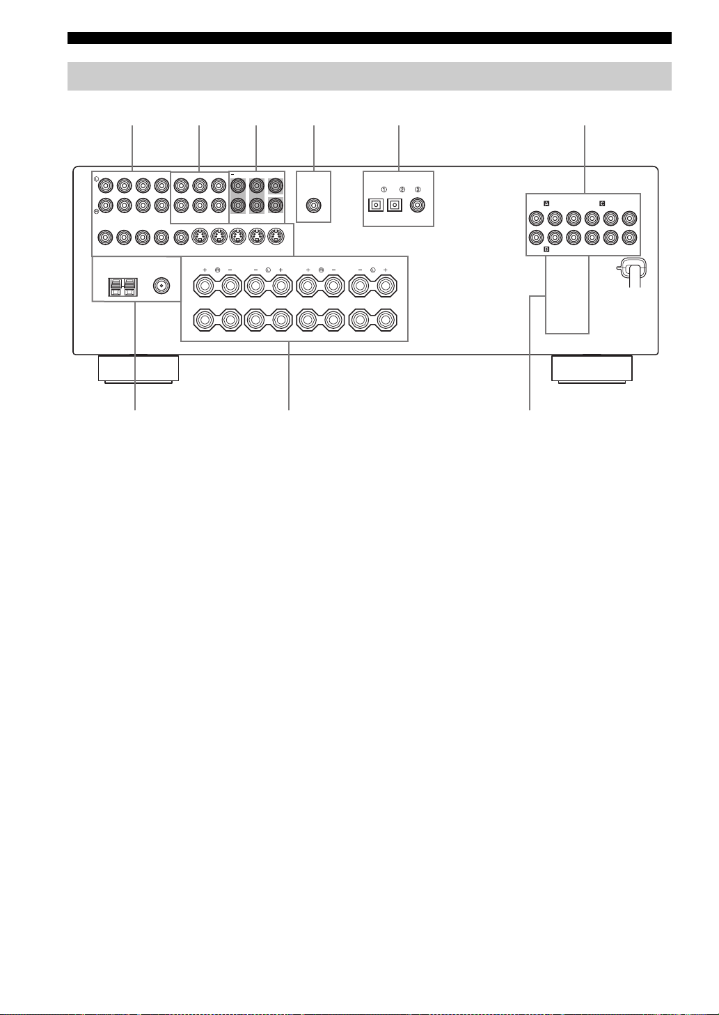
Rear panel
654321
AUDIO AUDIO
CD
(PLAY)
IN OUT
DTV/CBL
DVR DVD DTV/CBL
FM ANT
UNBAL.
MONITOR
OUT
75Ω
A
B
DVD
VIDEO S VIDEO
TUNER SPEAKERS
AM
ANT
GND
7
MULTI CH INPUT
CENTER
MD/
OUT
IN
CD-R
(REC)
FRONT
SUB
SURROUND
WOOFER
OUT
IN
DVR
MONITOR
OUT
FRONT
89
1 Video component jacks
See pages 17 and 18 for connection information.
2 Audio component jacks
See page 20 for connection information.
3 MULTI CH INPUT jacks
See page 21 for connection information.
4 SUBWOOFER OUTPUT jack
See page 13 for connection information.
5 DIGITAL INPUT jacks
See pages 18 and 19 for connection information.
OUTPUT DIGITAL INPUT
SUB
WOOFER
CENTER
SURROUND
DVD DV D
SURROUND BACK
DTV/CBL
OPTICAL
6 COMPONENT VIDEO jacks
See pages 17 and 18 for connection information.
7 Antenna terminals
See page 22 for connection information.
8 Speaker terminals
See page 12 for connection information.
9 AC OUTLET(S)
Use to supply power to your other audiovisual
components.
See page 23 for details.
COAXIAL
COMPONENT VIDEO
DVD DVR
RPBY
P
AC OUTLETS
MONITOR OUTDTV/CBL
PRPBY
10
■ VOLTAGE SELECTOR
(Asia and General models only)
See page 23 for details.
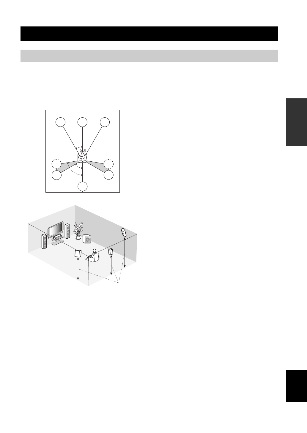
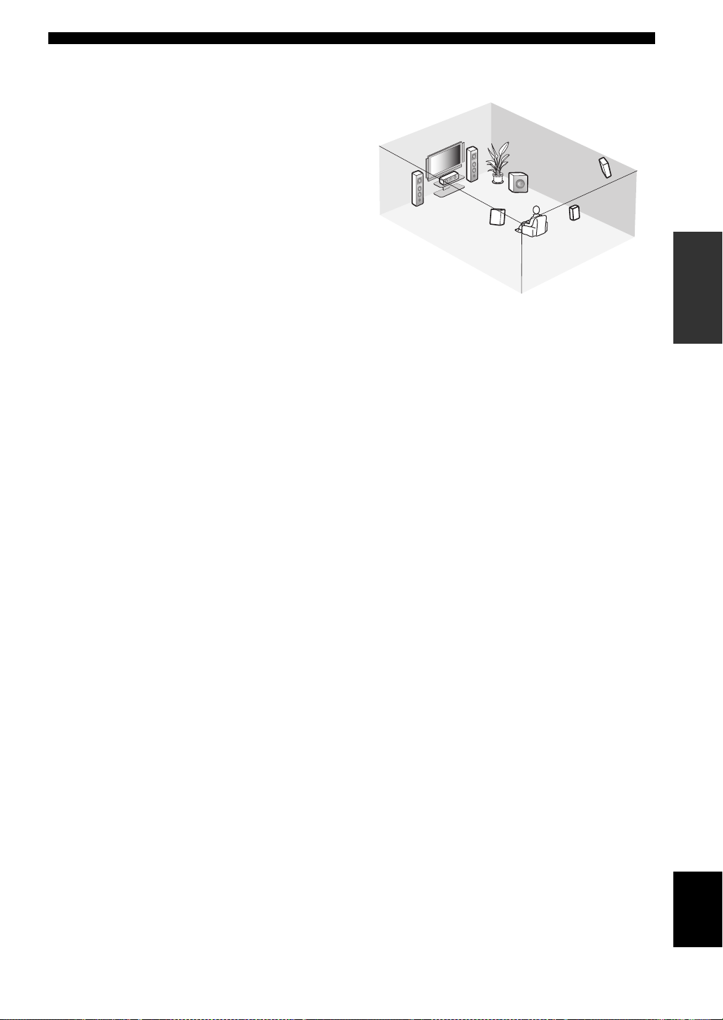
Placing speakers
CONNECTIONS
CONNECTIONS
The speaker layout below shows the standard ITU-R*
speaker setting. You can use it to enjoy CINEMA DSP and
multi-channel audio sources.
*
ITU-R is the radio communication sector of the ITU
(International Telecommunication Union).
FL
SL
SL
C
30˚
60˚
80˚
SB
FR
SR
SR
FR
FL
SW
SR
C
SL
SB
1.8 m (6 ft)
Front speakers (FL and FR)
The front speakers are used for the main source sound plus
effect sounds. Place these speakers at an equal distance
from the ideal listening position. The distance of each
speaker from each side of the video monitor should be the
same.
Center speaker (C)
The center speaker is for the center channel sounds
(dialog, vocals, etc.). If for some reason it is not practical
to use a center speaker, you can do without it. Best results,
however, are obtained with the full system. Place the
center speaker centrally between the front speakers and as
close to the monitor as possible, such as directly over or
under it.
Surround speakers (SL and SR)
The surround speakers are used for effect and surround
sounds. Place these speakers behind your listening
position, facing slightly inwards, about 1.8 m (6 ft) above
the floor.
Surround back speaker (SB)
The surround back speaker supplements the surround
speakers and provides more realistic front-to-back
transitions. Place this speaker directly behind the listening
position and at the same height as the surround speakers.
Subwoofer (SW)
The use of a subwoofer with a built-in amplifier, such as
the YAMAHA Active Servo Processing Subwoofer
System, is effective not only for reinforcing bass
frequencies from any or all channels, but also for hi-fi
stereo reproduction of the LFE (low-frequency effect)
channel included in Dolby Digital and DTS sources. The
position of the subwoofer is not so critical, because low
bass sounds are not highly directional. But it is better to
place the subwoofer near the front speakers. Turn it
slightly toward the center of the room to reduce wall
reflections.
PREPARATION
11
English
CONNECTIONS
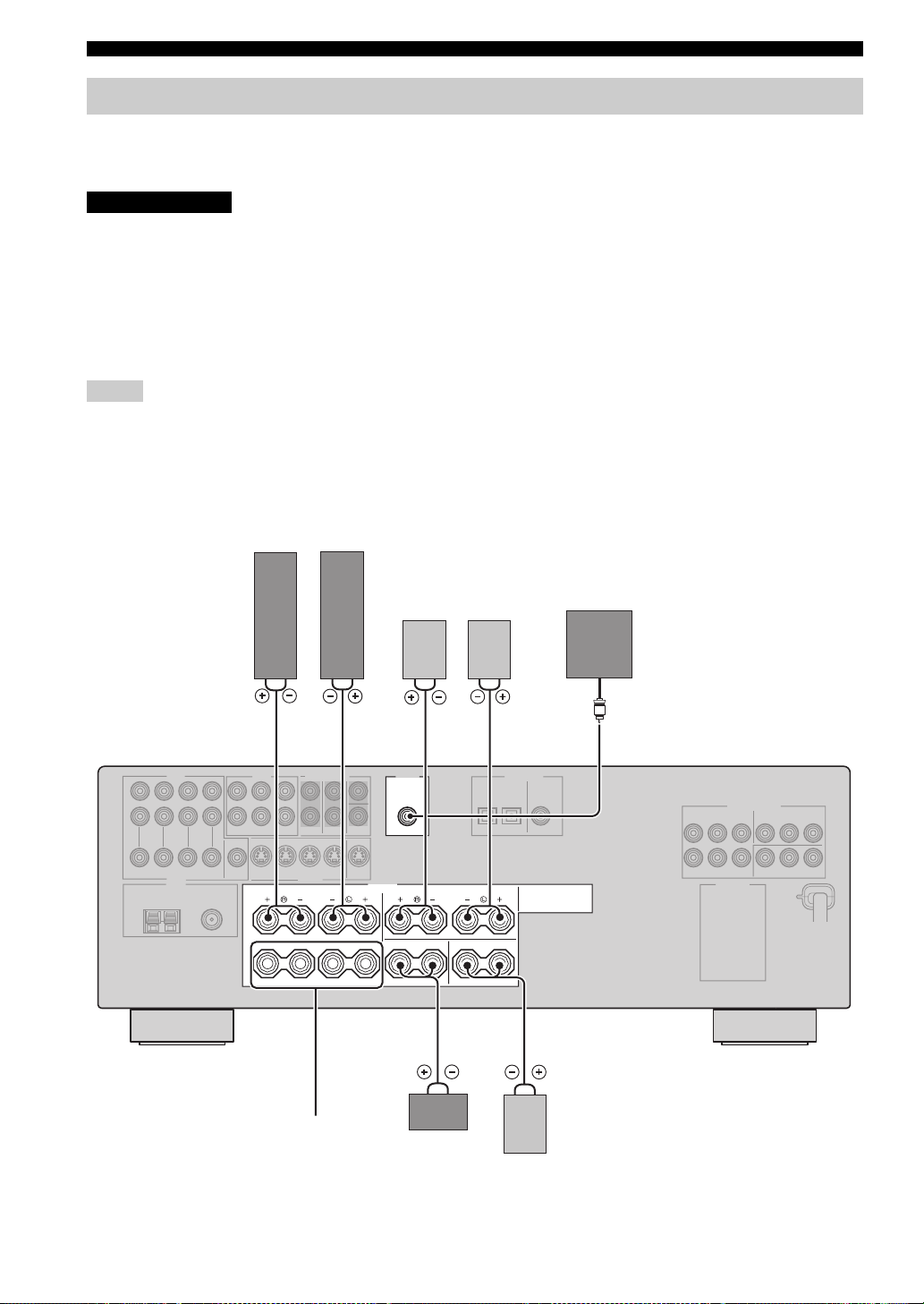
Connecting speakers
Be sure to connect the left channel (L), right channel (R), “+” (red) and “–” (black) properly. If the connections are faulty,
no sound will be heard from the speakers, and if the polarity of the speaker connections is incorrect, the sound will be
unnatural and lack bass.
CAUTION
• Before connecting the speakers, make sure that this unit is in the standby mode (see page 25).
• Do not let the bare speaker wires touch each other or do not let them touch any metal part of this
unit. This could damage this unit and/or speakers.
• Use magnetically shielded speakers. If this type of speakers still creates the interference with the
monitor, place the speakers away from the monitor.
• If you are to use 4 or 6 ohm speakers, be sure to set “SP IMP.” to “6ΩMIN” before using this unit
(see page 24).
Notes
• A speaker cord is actually a pair of insulated cables running side by side. Cables are colored or shaped differently, perhaps with a
stripe, groove or ridge. Connect the striped (grooved, etc.) cable to the “+” (red) terminals of this unit and your speaker. Connect the
plain cable to the “–” (black) terminals.
• The low-frequency signals of other speakers set to “SML” (or “SMALL”) to “NONE” in “SPEAKER SET” (see pages 70 and 71) are
directed to the speakers selected in “BASS OUT” (see page 71).
Front speakers
LeftRight
Right
Left
21
OUTPUT
SUB
WOOFER
Surround speakers
FRONT
A
B
SPEAKERS
CENTERCLASS 2 WIRING SURROUND BACK
SURROUND
54
Subwoofer
7
12
Front
speakers (B)
3
speaker
6
Center
Surround back
speaker
FRONT terminals
Connect one or two front speaker systems (1, 2) to these
terminals. If you use only one front speaker system,
connect it to the FRONT A or B terminal.
CONNECTIONS
CENTER terminals
Connect a center speaker (3) to these terminals.
SURROUND terminals
Connect surround speakers (4, 5) to these terminals.
SURROUND BACK terminals
Connect a surround back speaker (6) to these terminals.
SUBWOOFER jack
Connect a subwoofer with a built-in amplifier (7) (such as
the YAMAHA Active Servo Processing Subwoofer
System) to this jack.
1
7
2
3
5
Speaker layout
4
6
PREPARATION
13
English
CONNECTIONS
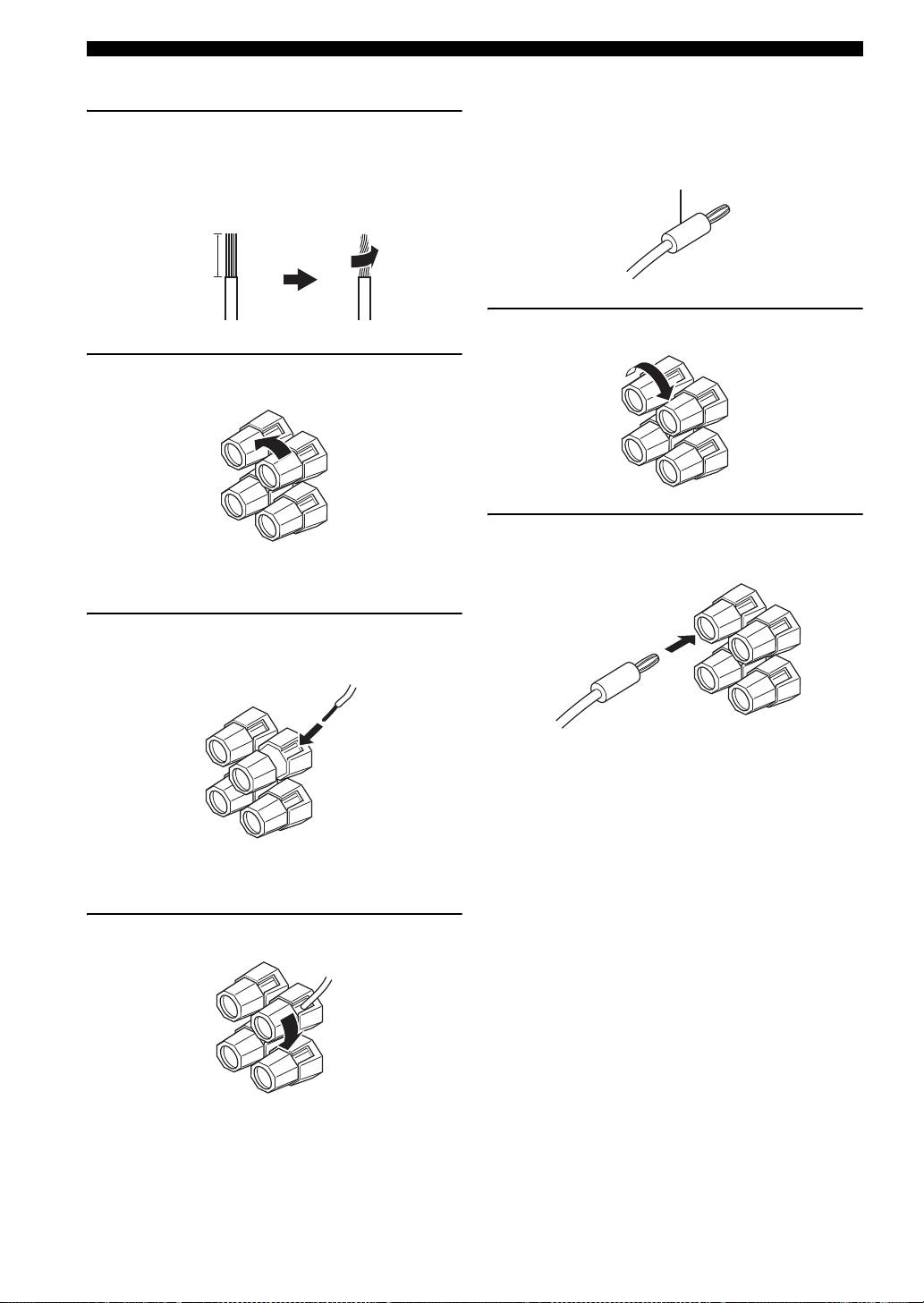
■ Connecting the speaker cable
1 Remove approximately 10 mm (0.4 in) of
insulation from the end of each speaker
cable and then twist the exposed wires of the
cable together to prevent short circuits.
10 mm (0.4 in)
2 Loosen the knob.
Red: positive (+)
Black: negative (–)
■ Connecting the banana plug
(except U.K., Europe and Asia models)
The banana plug is a single-pole electrical connector
widely used to terminate speaker cables.
Banana plug
1 Tighten the knob.
2 Insert the banana plug connector into the
end of the corresponding terminal.
3 Insert one bare wire into the hole on the side
of each terminal.
Red: positive (+)
Black: negative (–)
4 Tighten the knob to secure the wire.
Red: positive (+)
Red: positive (+)
Black: negative (–)
Black: negative (–)
14
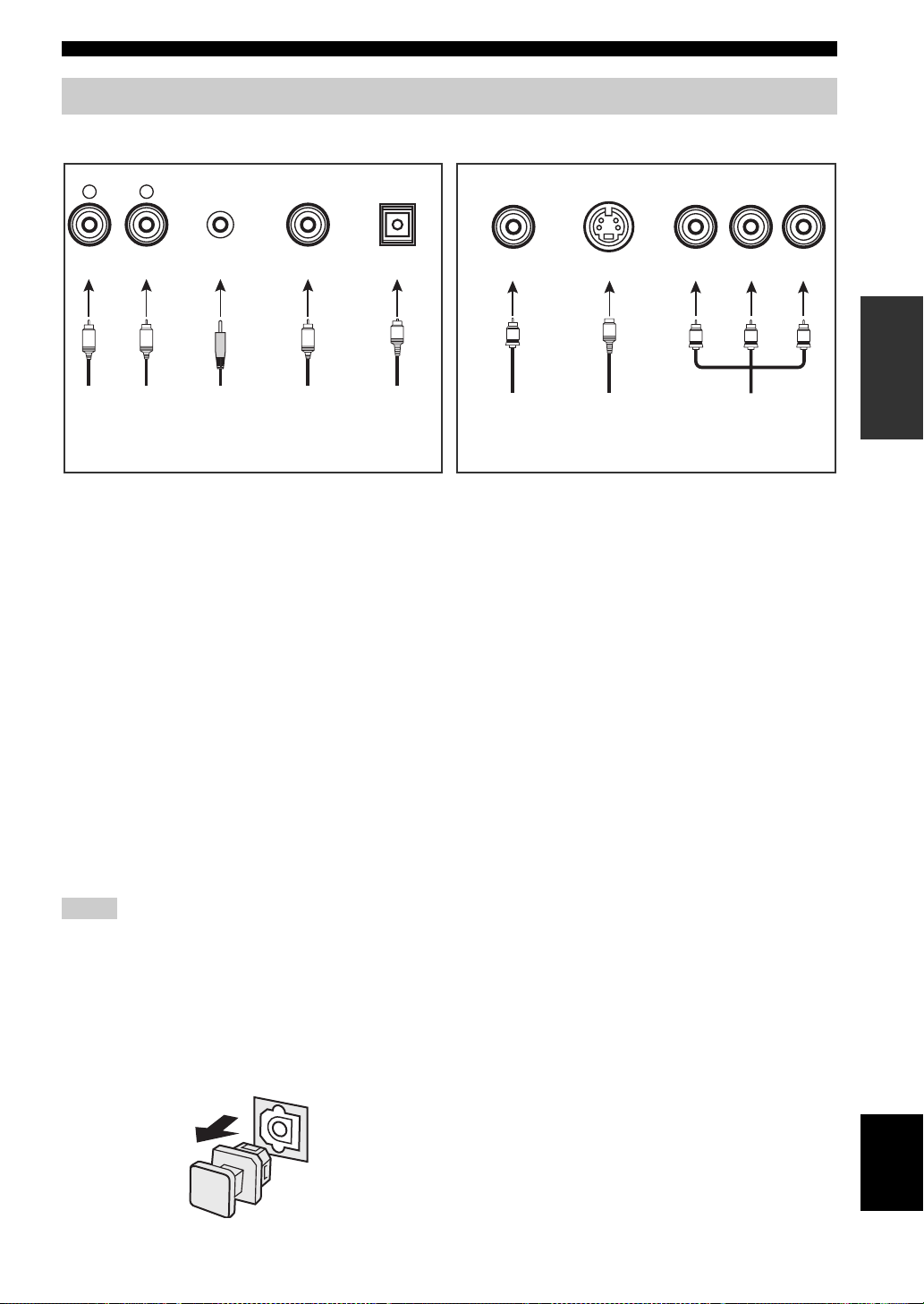
Information on jacks and cable plugs
Audio jacks and cables Video jacks and cables
M
DIGITAL AUDIO
COAXIAL
C
DIGITAL AUDIO
OPTICAL
O
AUDIO
L
(Red)(White) (Orange)
L
PORTABLE
R
R
VIDEO S VIDEO
V
S
CONNECTIONS
COMPONENT VIDEO
Y PB PR
(Green)
(Blue)(Green)(Yellow)
PB
Y
(Red)(Green)
PREPARATION
R
P
Left and right
analog audio
cable plug
Stereo
analog
audio
mini cable
plug
Coaxial
digital audio
cable plug
Optical
digital
audio cable
plug
■ Audio jacks
This unit has four types of audio jacks. Connection
depends on the availability of audio jacks on your other
components.
AUDIO jacks
For conventional analog audio signals transmitted via left
and right analog audio cables. Connect red plugs to the
right jacks and white plugs to the left jacks.
PORTABLE jack
For analog audio signals transmitted via stereo analog
audio mini cables.
DIGITAL AUDIO COAXIAL jacks
For digital audio signals transmitted via coaxial digital
audio cables.
DIGITAL AUDIO OPTICAL jacks
For digital audio signals transmitted via optical digital
audio cables.
Notes
• You can use the digital jacks to input PCM, Dolby Digital and
DTS bitstreams. When you connect components to both the
COAXIAL and OPTICAL jacks, priority is given to the signals
input at the COAXIAL jack. All digital input jacks are
compatible with 96-kHz sampling digital signals.
• Pull out the cap from the optical jack before you connect the
fiber optic cable. Do not discard the cap. When you are not
using the optical jack, be sure to put the cap back in place. This
cap protects the jack from dust.
Composite
video cable
plug
S-video
cable plug
Component
video cable
plug
■ Video jacks
This unit has three types of video jacks. Connection
depends on the availability of input jacks on your video
monitor.
VIDEO jacks
For conventional composite video signals transmitted via
composite video cables.
S VIDEO jacks
For S-video signals, separated into the luminance (Y) and
chrominance (C) video signals transmitted on separate
wires of S-video cables.
COMPONENT VIDEO jacks
For component video signals, separated into the
luminance (Y) and chrominance (P
transmitted on separate wires of component video cables.
B, PR) video signals
15
English
CONNECTIONS
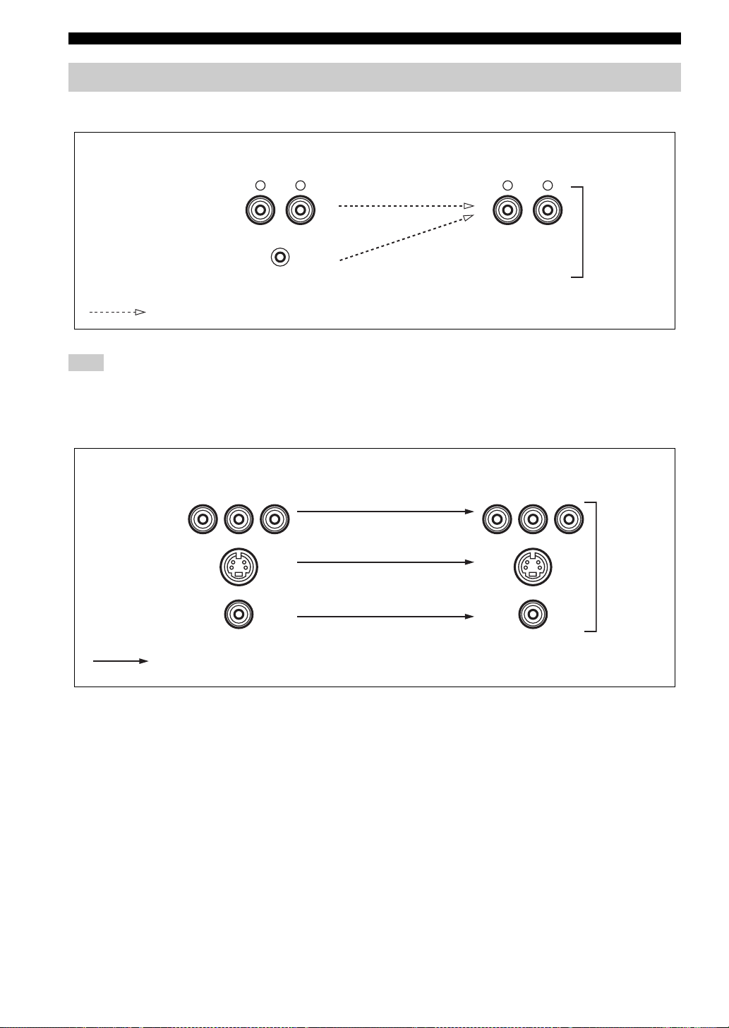
Audio and video signal flow
■ Audio signal flow for AUDIO OUT (REC)
Input
AUDIO
Output
AUDIO OUT (REC)
L RRL
Analog audio
PORTABLE
Analog output
Note
This unit handles digital and analog signals independently. Thus, audio signals input at the analog jacks are output only at the analog
AUDIO OUT (REC) jacks.
■ Video signal flow for MONITOR OUT
Input
Y PBP
R
Output
(MONITOR OUT)
Y PBP
R
COMPONENT
VIDEO
S VIDEO
Analog video
16
VIDEO
Through
CONNECTIONS
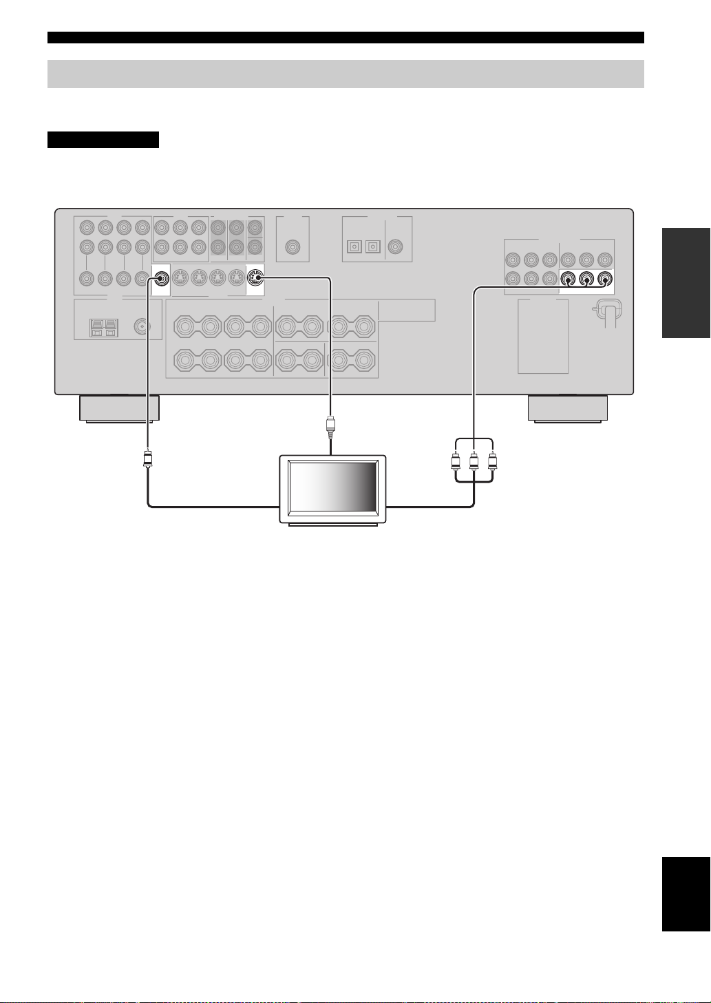
Connecting a TV
Connect your TV to the VIDEO MONITOR OUT jack, the S VIDEO MONITOR OUT jack or the COMPONENT
VIDEO MONITOR OUT jacks of this unit.
CAUTION
Do not connect this unit or other components to the AC power supply until all connections between
components are complete.
MONITOR
VIDEO S VIDEO
OUT
V
MONITOR
OUT
Video in
S
S-video in
TV
Component video in
COMPONENT VIDEO
PRPBY
PRPBY
MONITOR OUT
PREPARATION
17
English
CONNECTIONS
Connecting a DVD player, a DVD recorder, a VCR or an STB
Connect your DVD player, DVD recorder, VCR or STB (set-top box) using the same type of video connections as those
made for your TV (see page 17). The cable TV receiver and the satellite receiver are examples of the STB.
CAUTION
Do not connect this unit or other components to the AC power supply until all connections between
components are complete.
Notes
• Be sure to make the same type of video connections as those made for your TV (see page 17). For example, if you connected your TV
to the VIDEO MONITOR OUT jack of this unit, connect your other components to the VIDEO jacks.
• To make a digital connection to a component other than the default component assigned to each DIGITAL INPUT jack, select the
corresponding setting for “OPTICAL IN” or “COAXIAL IN” in “INPUT ASSIGN” (see page 73).
• If you connect your DVD player to both the DIGITAL INPUT (OPTICAL) and the DIGITAL INPUT (COAXIAL) jacks, priority is
given to the signals input at the DIGITAL INPUT (COAXIAL) jack.
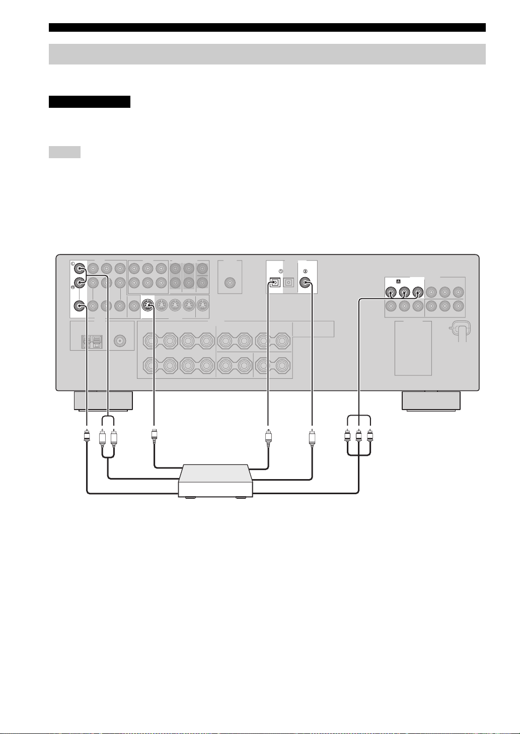
■ Connecting a DVD player
AUDIO
DVD
VIDEO S VIDEO
V
LR
S-Video out
S-Video out
DVD
S
Audio out
Video out
Optical audio out
DVD Player
DIGITAL INPUT
DVD DV D
COAXIAL
OPTICAL
O
C
Coaxial audio out
Component video out
Y PB
COMPONENT VIDEO
DVD
P
RPBY
PR
18
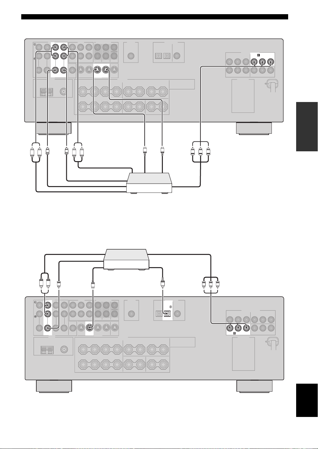
■ Connecting a DVD recorder or a VCR
AUDIO
COMPONENT VIDEO
CONNECTIONS
DVR
RPBY
P
IN OUT
DVR
VIDEO S VIDEO
V
R L R L
V
■ Connecting an STB
Audio out
Video out
OUT
IN
DVR
S-video out S-video in
Audio in
Video in
Video out
Audio out
Cable TV receiver or
satellite receiver
S
S
DVD recorder or
VCR
Component video out
Optical audio out
PREPARATION
PRPBY
Component video out
S-video out
LR
V Y PB PR
AUDIO
DTV/CBL
VIDEO S VIDEO
S
DTV/CBL
O
OPTICAL
DIGITAL INPUT
DTV/CBL
COMPONENT VIDEO
DTV/CBL
RPBY
P
English
19
CONNECTIONS
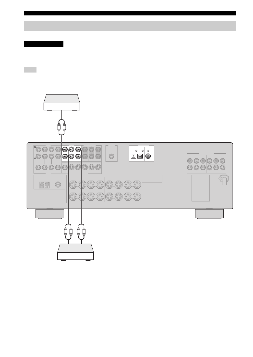
Connecting a CD player, an MD player or a tape deck
Connect your CD player, MD player or tape deck via analog connection.
CAUTION
Do not connect this unit or other components to the AC power supply until all connections between
components are complete.
Note
To make a digital connection to a component other than the default component assigned to each DIGITAL INPUT jack, select the
corresponding setting for “OPTICAL IN” or “COAXIAL IN” in “INPUT ASSIGN” (see page 73).
CD Player
Audio out
LR
Audio out
AUDIO
MD/
OUT
IN
CD-R
CD
(REC)
(PLAY)
LR LR
MD recorder
or tape deck
Audio in
DIGITAL INPUT
DVD DV D
DTV/CBL
OPTICAL
COAXIAL
20
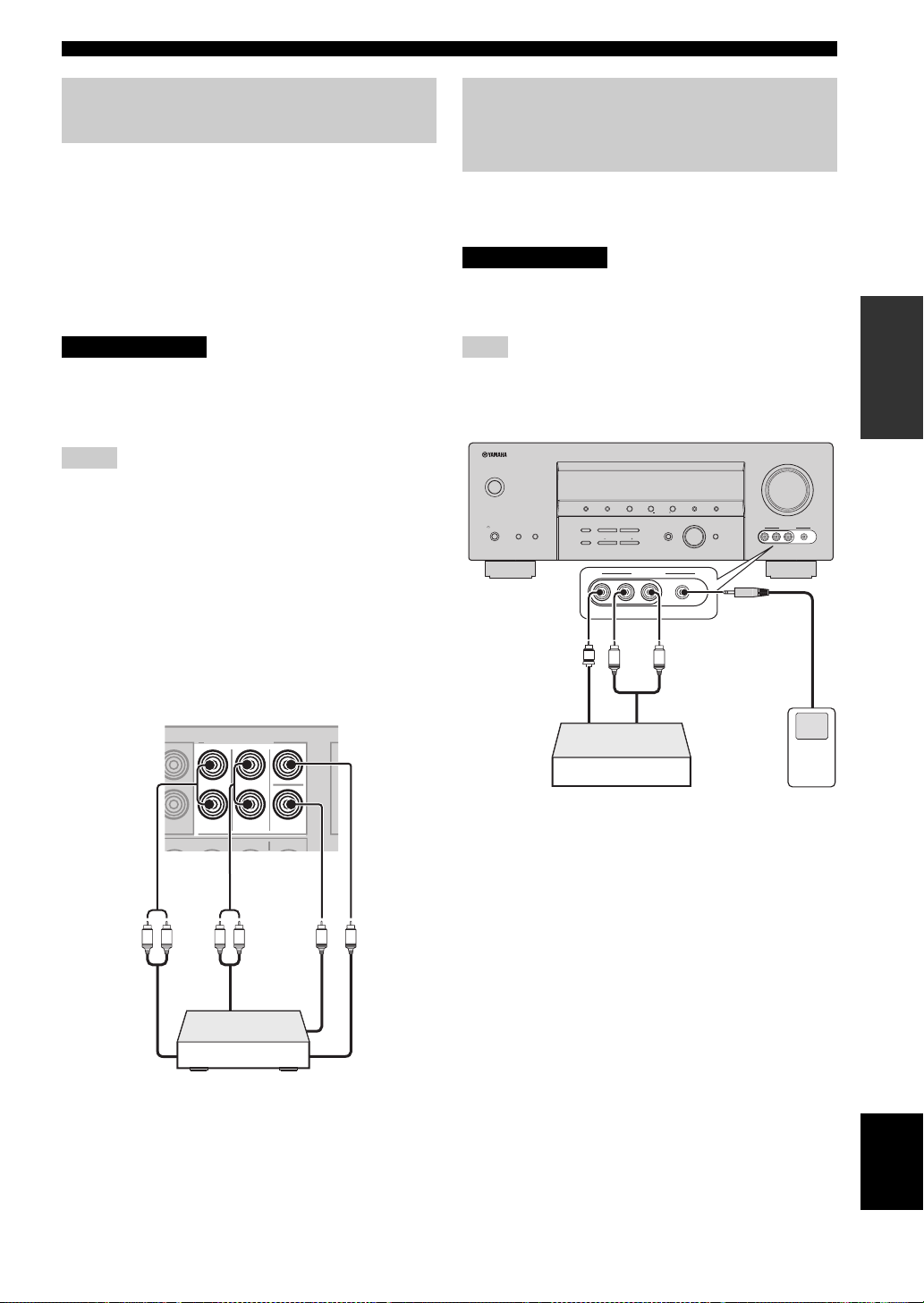
CONNECTIONS
Connecting a multi-format player
or an external decoder
This unit is equipped with 6 additional input jacks
(FRONT L/R, CENTER, SURROUND L/R and
SUBWOOFER) for discrete multi-channel input from a
multi-format player, external decoder, sound processor or
pre-amplifier. Connect the output jacks on your multiformat player or external decoder to the MULTI CH
INPUT jacks. Be sure to match the left and right output
jacks to the left and right input jacks for the front and
surround channels.
CAUTION
Do not connect this unit or other components to
the AC power supply until all connections
between components are complete.
Notes
• When you select the component connected to the MULTI CH
INPUT jacks as the input source (see page 36), this unit
automatically turns off the digital sound field processor, and
you cannot select sound field programs.
• This unit does not redirect signals input at the MULTI CH
INPUT jacks to accommodate for missing speakers. We
recommend that you connect at least a 5.1-channel speaker
system before using this feature.
• When headphones are used, signals are output only from the
front left and right channels.
Connecting a game console,
a video camera or a portable audio
player
Use the VIDEO AUX jacks on the front panel to connect a
game console, a video camera or a portable audio player to
this unit.
CAUTION
Be sure to turn off the volume of this unit and
other components before making connections.
Note
The audio signals input at the PORTABLE mini jack take priority
over the ones input at the AUDIO L/R jacks.
VOLUME
STANDBY
SILENT CINEMA
/ON
PHONES
SPEAKERS
BA
Video out
PRESET/TUNING
TONE CONTROL
EDIT
STRAIGHT
EFFECT
V
A/B/C/D/E
FM/AM
NEXT
l PROGRAM h
BASS/TREBLE
VIDEO AUX
VIDEO PORTABLEL AUDIO R
L
l
PRESET/TUNING
h
MAN’L/AUTO FM
LEVEL
INPUT MODE
R
Audio out
TUNING MODE
MEMORY
AUTO/MAN’L
INPUT
MULTI CH
INPUT
VIDEO AUX
VIDEO PORTABLEL AUDIO R
M
Audio
out
PREPARATION
MULTI CH INPUT
FRONT
L R L R
Front out Surround
out
Multi-format player or
external decoder
SURROUND
CENTER
SUB
WOOFER
Subwoofer
out
Center
out
Game console or
video camera
Portable audio
player
English
21
CONNECTIONS
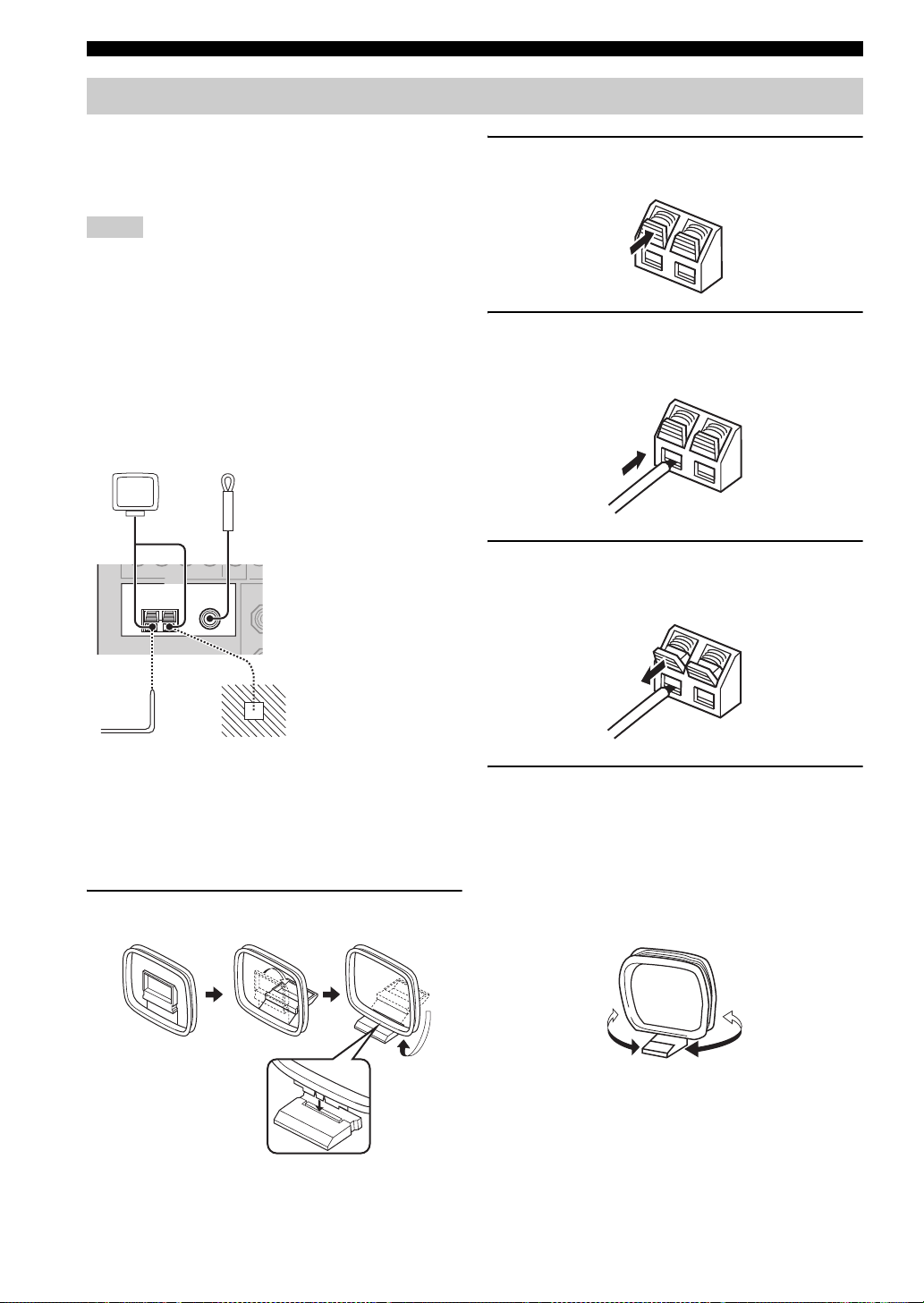
Connecting the FM and AM antennas
Both FM and AM indoor antennas are supplied with this
unit. In general, these antennas should provide sufficient
signal strength. Connect each antenna correctly to
designated terminals.
Notes
• Be sure to set the tuner frequency step (Asia and General
models only) according to the frequency spacing in your area
(see page 77).
• The AM loop antenna should be placed away from this unit.
• The AM loop antenna should always be connected, even if an
outdoor AM antenna is connected to this unit.
• A properly installed outdoor antenna provides clearer reception
than an indoor one. If you experience poor reception quality,
install an outdoor antenna. Consult the nearest authorized
YAMAHA dealer or service center about outdoor antennas.
AM loop antenna
(supplied)
Indoor FM antenna
(supplied)
TUNER
FM ANT
AM
ANT
75
Ω
GND
UNBAL.
2 Press and hold the tab of the AM ANT
terminal.
3 Insert one of the AM loop antenna lead wires
into the AM ANT terminal.
4 Release the tab of the AM ANT terminal back
into place.
Ground
For maximum safety and
minimum interference,
connect the antenna GND
terminal to a good earth
Outdoor AM antenna
Use a 5 to 10 m (16.4 to 32.8 ft) of
vinyl-covered wire extended outdoors
from a window.
ground. A good earth ground
is a metal stake driven into
moist earth.
■ Connecting the AM loop antenna
1 Set up the AM loop antenna.
5 Repeat steps 2 through 4 to connect the
other lead wire to the GND terminal.
y
Once you have properly connected the AM loop antenna to
this unit, orient the AM loop antenna for the best reception
when you tune into AM stations (see page 43).
22
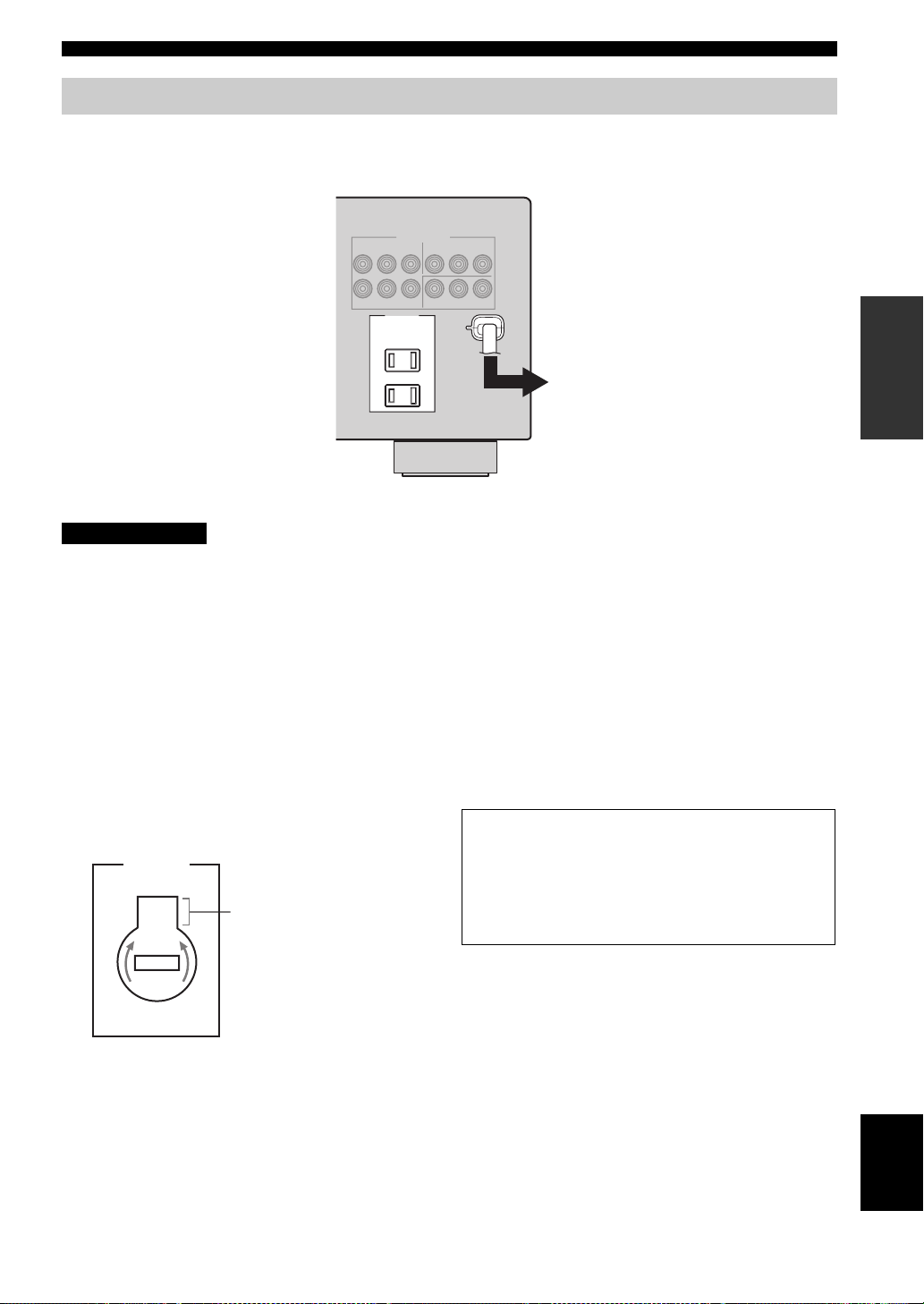
Connecting the power cable
Once all connections are complete, plug the power cable into the AC wall outlet.
(U.S.A. model)
CONNECTIONS
AC OUTLETS
CAUTION
VOLTAGE SELECTOR
(Asia and General models only)
The VOLTAGE SELECTOR on the rear panel of this unit
must be set for your local voltage BEFORE plugging the
power cable into the AC wall outlet. Improper setting of
the VOLTAGE SELECTOR may cause damage to this
unit and create a potential fire hazard.
Rotate the VOLTAGE SELECTOR clockwise or
counterclockwise to the correct position using a
straight slot screwdriver.
Voltages are as follows:
Asia model ……………………. 220/230–240 V AC, 50/60 Hz
General model ……110/120/220/230–240 V AC, 50/60 Hz
VOLTAGE
SELECTOR
230240V
Voltage indication
PREPARATION
To the AC wall outlet
AC OUTLET(S) (SWITCHED)
U.K. and Australia models ………………………………. 1 outlet
Korea model……………………………………………………… None
Other models ………………………………………………… 2 outlets
Use these outlet(s) to supply power to any connected
components. Connect the power cable of your other
components to these outlet(s). Power to these outlet(s) is
supplied when this unit is turned on. However, power to
these outlet(s) is cut off when this unit is in the standby
mode or the power cable of this unit is disconnected from
the AC wall outlet. For information on the maximum
power or the total power consumption of the components
that can be connected to these outlet(s), see
“SPECIFICATIONS” on page 89.
Memory back-up
The memory back-up circuit prevents the stored data
from being lost even if this unit is in the standby mode.
However, the stored data will be lost in case the power
cable is disconnected from the AC wall outlet or if the
power supply is cut off for more than one week.
23
English
CONNECTIONS
Setting the speaker impedance
CAUTION
If you are to use 4 or 6 ohm speakers, set “SP
IMP.” to “6ΩMIN” as follows BEFORE using this
unit.
VOLUME
STANDBY
2,5
SILENT CINEMA
/ON
PHONES
SPEAKERS
PRESET/TUNING
EDIT
STRAIGHT
BA
EFFECT
TONE CONTROL
2,4
l
FM/AM
PROGRAM
BASS/TREBLE
l
PRESET/TUNING
h
A/B/C/D/E
NEXT
h
TUNING MODE
MEMORY
AUTO/MAN’L
MAN’L/AUTO FM
LEVEL
INPUT
INPUT MODE
MULTI CH
INPUT
VIDEO AUX
VIDEO PORTABLEL AUDIO R
3
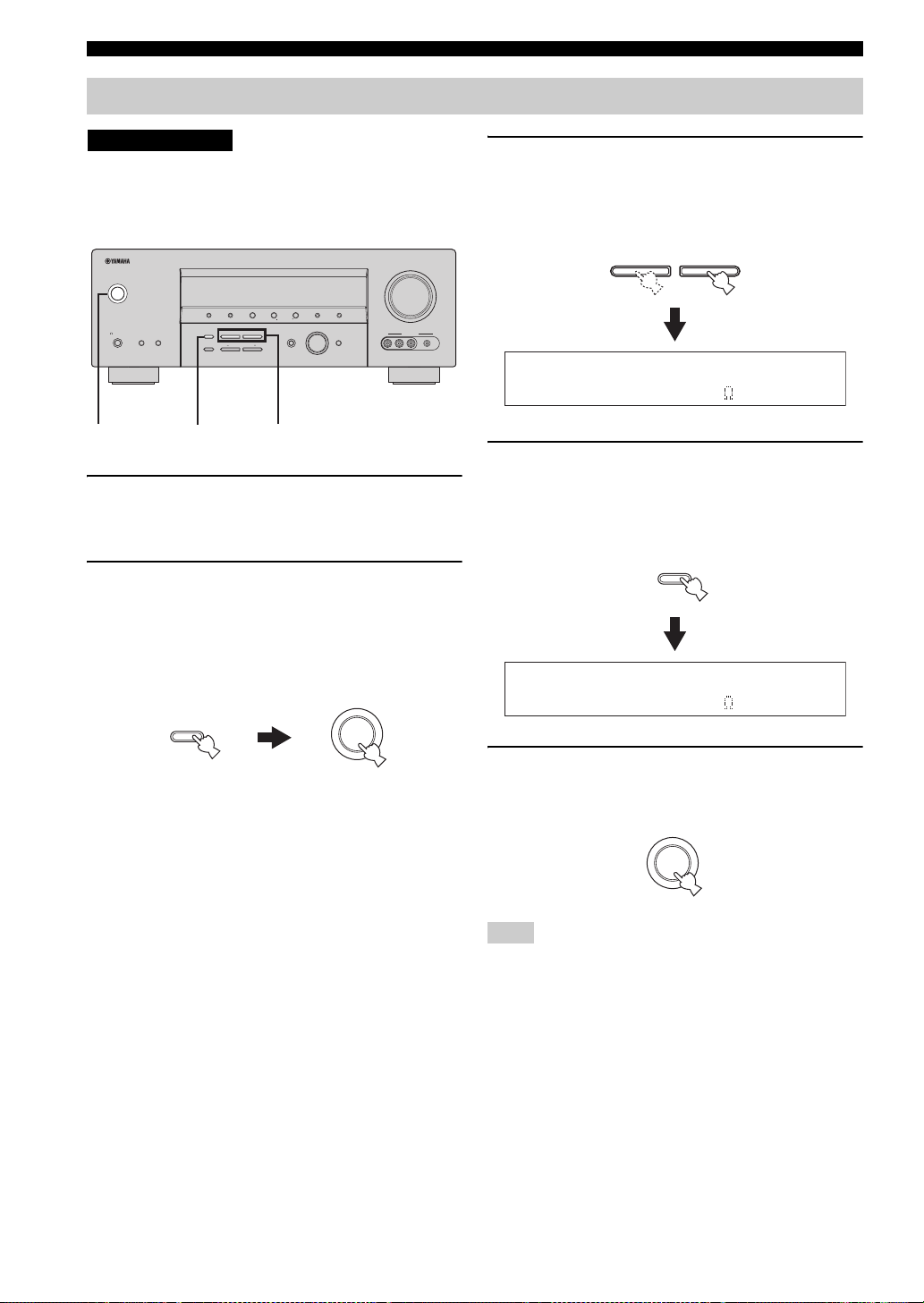
1 Make sure this unit is in the standby mode.
See page 25 for details about turning on this unit or
standby mode.
2 Press and hold STRAIGHT (EFFECT) on the
front panel and then press STANDBY/ON to
turn on this unit.
This unit turns on, and the advanced setup menu
appears in the front panel display.
3 Press PROGRAM l / h buttons on the front
panel to select “SP IMP.”.
The following display appears in the front panel
display.
l PROGRAM h
SP IMP.-8 MIN
4 Press STRAIGHT (EFFECT) on the front
panel repeatedly to select “6ΩMIN”.
The following display appears in the front panel
display.
STRAIGHT
EFFECT
STRAIGHT
EFFECT
While holding
down
STANDBY
/ON
SP IMP.-6 MIN
5 Press STANDBY/ON on the front panel to
save the new setting and set this unit to the
standby mode.
STANDBY
/ON
Note
The setting you made is reflected next time you turn on this unit.
24
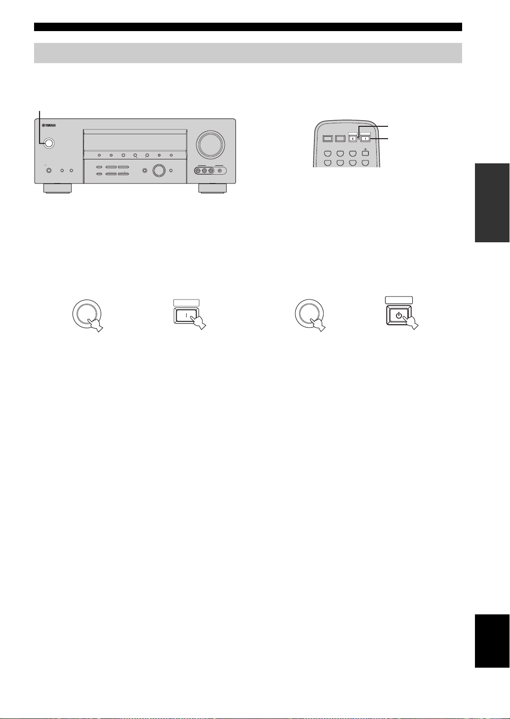
Turning on this unit and setting it to the standby mode
When all connections are complete, turn on this unit.
STANDBY/ON
CONNECTIONS
VOLUME
STANDBY
SILENT CINEMA
/ON
PHONES
SPEAKERS
PRESET/TUNING
EDIT
STRAIGHT
BA
EFFECT
TONE CONTROL
FM/AM
l
PROGRAM
BASS/TREBLE
l
PRESET/TUNING
h
A/B/C/D/E
NEXT
h
TUNING MODE
MEMORY
AUTO/MAN’L
MAN’L/AUTO FM
LEVEL
INPUT
INPUT MODE
MULTI CH
INPUT
VIDEO AUX
VIDEO PORTABLEL AUDIO R
■ Turning on the power
Press STANDBY/ON on the front panel (or
POWER on the remote control) to turn on this
unit.
STANDBY
/ON
Front panel
or
POWER
Remote control
POWER POWER
STANDBY
POWER
AVTV
CD
MD/CD-R
TUNER
DVR
DTV/CBL
POWER
V-AUXDVD
■ Setting this unit to the standby mode
Press STANDBY/ON on the front panel again (or
STANDBY on the remote control) to set this unit
to the standby mode.
STANDBY
STANDBY
STANDBY
/ON
Front panel Remote control
or
PREPARATION
25
English
BASIC SETUP
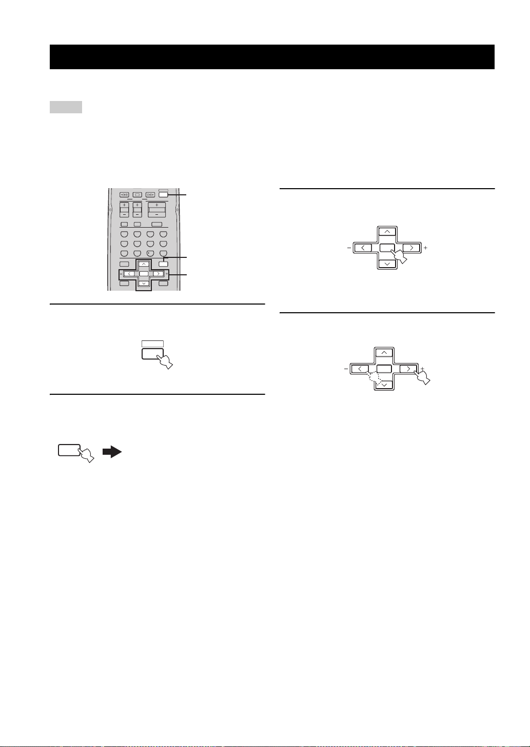
BASIC SETUP
The “BASIC SETUP” feature is a useful way to set up your system quickly and with minimal effort.
Notes
• Make sure you disconnect your headphones from this unit.
• If you wish to configure this unit manually using more precise adjustments, use the detailed parameters in “SOUND MENU”
(see page 70).
• Altering any parameters in “BASIC SETUP” resets all parameters manually adjusted in “SOUND MENU” (see page 70).
• Initial settings are indicated in bold under each parameter.
• Press RETURN on the remote control to return to the previous menu level.
FREQ/TEXT EON
MODE PTY SEEK
TV VOL TV CH
TV MUTE TV INPUT
STEREO
SPEAKERS
LEVEL
BAND
A/B/C/D/E A/B/C/D/E
DAB MEMORY
1 Press AMP on the remote control.
SELECT
ENHANCER
ENTER
PRESET/CH
AMP
START
VOLUME
MUTE
NIGHT
MOVIEENTERTAINMUSIC
4321
DIRECT ST.EXTD SUR.STANDARD
81070965
STRAIGHT
ENT.
SET MENU
MENUTITLE
SRCH MODE
DISPLAYRETURN
1
2,12
3-11
3 Press ENTER to enter “BASIC SETUP”.
ENTER
A/B/C/D/E A/B/C/D/E
PRESET/CH
The “ROOM” appears in the front panel display.
4 Press j / i to select the desired setting.
AMP
2 Press SET MENU.
“BASIC SETUP” appears in the front panel display.
SET MENU
MENU
SRCH MODE
.
BASIC SETUP
ENTER
A/B/C/D/E A/B/C/D/E
PRESET/CH
ROOM: S >M L
Select the size of the room where you have installed
your speakers. In general, the room sizes are defined
as follows:
Choices: S, M, L
[U.S.A. and Canada models]
S (small) 16 x 13ft, 200ft
M (medium) 20 x 16ft, 300ft
L (large) 26 x 19ft, 450ft
[Other models]
S (small) 3.6 x 2.8m, 10m
M (medium) 4.8 x 4.0m, 20m
L (large) 6.3 x 5.0m, 30m
2
(4.8 x 4.0m, 20m2)
2
(6.3 x 5.0m, 30m2)
2
(7.9 x 5.8m, 45m2)
2
2
2
26
Loading…
Google Ads:
Популярность:
16066 просмотры
Подсчет страниц:
93 страницы
Тип файла:
Размер файла:
2.1 Mb
Google Ads:
Google Ads:
-
Yamaha YHT-585B Брошюра
Популярность:
482 просмотры
Подсчет страниц:
2 страницы
Тип файла:
PDF
Размер файла:
287 Kb
Найди любой мануал:
Например: Sony VGN-FW460J/T
Вы можете бесплатно скачать Руководство по эксплуатации для Yamaha RX-V459.
Также вы сможете прочесть онлайн этот документ без скачивания.
Скачать Руководство по эксплуатации для Yamaha RX-V459
Тип файла
PDF
Размер
2.1 Mb
Кол-во страниц
93
Просмотров
16067
Читать онлайн Руководство по эксплуатации для Yamaha RX-V459 (Страница 1)

Другие Стереосистемы Yamaha RX-V459
Топ Yamaha Стереосистемы
Ранее вы смотрели
Эта страница полезна для вас? Поделитесь ссылкой:
Предпросмотр документа
· инструкция (руководство, документация) для ресивера Yamaha RX-V459 (HTR-5940)
·
27 июля 2024 етырий
сервис мануал ( схема )
Файл: man3695-yamaha_rx-v459_htr-5940_dsp-ax459_htr-5935_av_receiver_av_amplifier.pdf
Размер: 14.43 Мб
Открыть файл
359 просмотров
добавить комментарий