
-
Страница 1
FORM 201.18-EG1 (200) Millennium Air Cooled Screw Liquid Chillers (STYLE F) ® 28971AR 80 — 420 TONS (310 — 1460 kW) 60 Hz 200, 230, 380, 460, & 575 Models 50 — 200 TONS ® M A N U F A C T U R E R C E R T I F I E D T O A R I A S C O M P L Y I N G W I T H A R I S T A N D A R D 5 5 0 / 5 9 0 W A T E R C H I L L I N G P A C K A G E S U S I N G C O[…]
-
Страница 2
YORK INTERNA TIONAL 2 NOMENCLA TURE The Model Number denotes the following characteristics of the unit: YORK Chiller YC = YORK Chiller Air-Cooled Compressor T ype S = Screw Nominal Capacity (tons) Unit Designator S = Standard Unit E = High Efficiency H = High Static Fans Design Series T ype Start Y = Star (WYE)-Delta X = Across-the-Line V oltage Co[…]
-
Страница 3
YORK INTERNA TIONAL FORM 201.18-EG1 3 YORK Millennium Air Cooled Screw Compressor machines are the state-of-the-art in air-cooled chillers, providing chilled fluids for all air conditioning applications. Completely self-contained and designed for outdoor installation, these chillers employ new , low noise, energy efficient, serviceable, semi-hermet[…]
-
Страница 4
YORK INTERNA TIONAL 4 Specifications These YORK air cooled chillers are shipped as a com- plete factory package. Each unit is completely as- sembled with all interconnecting refrigerant piping and internal wiring, ready for field installation: COMPLETE FACTOR Y PACKAGE • Each compressor is installed on its own indepen- dent refrigerant circuit, w[…]
-
Страница 5
YORK INTERNA TIONAL FORM 201.18-EG1 5 REFRIGERANT CIRCUIT • Independent refrigerant circuits per compressor , each using copper refrigerant pipe formed on com- puter controlled bending machines. This eliminates over 60% of system piping brazed joints as com- pared to designs that use fittings, resulting in a highly reliable and leak resistant sys[…]
-
Страница 6
YORK INTERNA TIONAL 6 Pulse width modulated (PWM) input for up to 40 ° F (22 ° C) total reset as standard. Optional Building Automation System interface input card for up to 40 ° F (22 ° C) reset using a: 4 to 20 milliamp, 0 to 10 VDC input, or discrete reset input. [ NOTE : The Standard MicroPanel can be directly connected to a YORK IS[…]
-
Страница 7
YORK INTERNA TIONAL FORM 201.18-EG1 7 Accessories and Options • CONTROL CIRCUIT TERMINAL STRIP – Provides power input terminals for field provided power input in lieu of factory mounted control circuit transformer . 1 15V , 1 ∅ Control Circuit Power T erminal Strip lo- cated in the Microprocessor Panel to accept a field provided control power[…]
-
Страница 8
YORK INTERNA TIONAL 8 Accessories and Options (Continued) and other corrosive applications except: strong al- kalies, oxidizers, and wet bromine, chlorine, and fluorine in concentrations greater than 100 ppm. ♦ Copper Fin Condenser Coils – Coils constructed with corrosion resistant copper fins. Not recom- mended in areas where units may be expo[…]
-
Страница 9
YORK INTERNA TIONAL FORM 201.18-EG1 9 • MUL TI-UNIT SEQUENCING – A separate Se- quencing Control Center is provided to handle se- quencing control of up to eight chillers in parallel based on mixed liquid temperature (interconnect- ing wiring by others). See Form 150.00-SG2 for more information. (Only one of the following op- tions can be offer[…]
-
Страница 10
YORK INTERNA TIONAL 10 T emperatures and Flows TEMPERA TURE AND FLOWS (English Units) NOTES: 1. For leaving brine temperature below 40 ° F (4.4 ° C), contact your nearest YORK office for application requirements. 2. For leaving water temperature higher than 55 ° F (12.8 ° C), contact the nearest YORK office for application guidelines. 3. The ev[…]
-
Страница 11
YORK INTERNA TIONAL FORM 201.18-EG1 11 TEMPERA TURE AND FLOWS (SI Units) MODEL LEA VING W A TER COOLER FLOW AIR ON NUMBER TEMPERA TURE ( ° C) (L/S) 3 CONDENSER ( ° C) YCAS MIN. 1 MAX. 2 MIN. MAX. MIN. MAX 0090EC 4.4 12.8 7.0 38.0 -17.7 51.7 0100EC 4.4 12.8 8.0 38.0 -17.7 51.7 01 10EC 4.4 12.8 8.0 38.0 -17.7 51.7 0120EC 4.4 12.8 8.0 38.0 -17.7 51.[…]
-
Страница 12
YORK INTERNA TIONAL 12 W ater Pressure Drop MODEL NUMBER YCAS COOLER 0090, 0100, 01 10, 0120, 0130, 0140 A 0150, 0160, 0170, 0180, 0200, 0210, 0230 B 0250, 0270, 0300, 0330 C 0360, 0400, 0440 D PRESSURE DROP (ft-H O) 2 A B C D 100.0 1000.0 1 10 100 W A TER FLO W (GPM) COOLER W A TER PRESSURE DR OP LD04481 ENGLISH UNITS[…]
-
Страница 13
YORK INTERNA TIONAL FORM 201.18-EG1 13 A B C D 1 10 100 1 100 10 1000 W A TER FLO W (l/s) COOLER W A TER PRESSURE DROP PRESSURE DROP (kP a) LD04482 SI UNITS MODEL NUMBER YCAS COOLER 0090, 0100, 01 10, 0120, 0130, 0140 A 0150, 0160, 0170, 0180, 0200, 0210, 0230 B 0250, 0270, 0300, 0330 C 0360, 0400, 0440 D[…]
-
Страница 14
YORK INTERNA TIONAL 14 Ratings – English Units NOTES: 1. k W = Compressor Input Power 2. EE R = Chiller EER (includes power from compressors, fans, and control panels 0.8 KW) 3. LCWT = Leaving Chilled W ater T emperature 4. Ratings based on 2.4 GPM cooler water per ton 5. Rated in accordance with ARI Standard 550/590-98 6. Certified in accordance[…]
-
Страница 15
YORK INTERNA TIONAL FORM 201.18-EG1 15 MODEL YCAS01 10EC 40.0 93.8 123.9 8.0 91.6 133.0 7.4 89.5 142.6 6.8 87.5 152.8 6.2 85.7 163.6 5.7 74.2 157.2 5.1 42.0 97.0 125.1 8.2 94.7 134.3 7.5 92.5 144.0 6.9 90.5 154.4 6.4 87.9 163.9 5.9 74.9 155.6 5.2 44.0 100.3 126.3 8.4 97.8 135.6 7.7 95.6 145.4 7.1 93.5 155.9 6.5 89.5 163.1 6.0 75.8 154.5 5.3 45.0 10[…]
-
Страница 16
YORK INTERNA TIONAL 16 Ratings – English Units LCWT AIR TEMPERA TURE ON CONDENSER ( ° F) ( ° F) 75 80 85 90 95 TONS kW EER T ONS kW EER TONS kW EER TONS kW EER TONS kW EER MODEL YCAS0140EC (IPL V = 1 1.3) 40.0 133.3 99.9 14.0 129.9 107.5 12.8 126.9 1 16.0 1 1.7 124.3 125.2 10.7 122.0 135.2 9.8 42.0 137.8 100.8 14.4 134.3 108.5 13.1 131.2 1 17.0[…]
-
Страница 17
YORK INTERNA TIONAL FORM 201.18-EG1 17 MODEL YCAS0140EC 40.0 1 19.9 145.9 9.0 1 18.1 157.4 8.2 1 16.5 169.7 7.6 1 15.1 182.7 7.0 1 13.7 196.3 6.5 102.4 195.2 5.9 42.0 123.8 147.1 9.2 121.8 158.8 8.4 120.1 171.2 7.8 1 18.6 184.3 7.2 1 17.3 198.1 6.6 103.2 193.5 6.0 44.0 127.7 148.3 9.4 125.7 160.1 8.6 123.9 172.6 7.9 122.3 185.9 7.3 120.8 199.8 6.8 […]
-
Страница 18
YORK INTERNA TIONAL 18 Ratings – English Units LCWT AIR TEMPERA TURE ON CONDENSER ( ° F) ( ° F) 75 80 85 90 95 TONS kW EER T ONS kW EER TONS kW EER TONS kW EER TONS kW EER MODEL YCAS0170EC (IPL V = 1 1.1) 40.0 170.8 138.8 13.4 166.1 148.7 12.2 161.5 159.2 1 1.2 157.7 171.0 10.2 153.9 183.4 9.3 42.0 176.6 140.7 13.7 171.7 150.7 12.5 167.2 161.5 […]
-
Страница 19
YORK INTERNA TIONAL FORM 201.18-EG1 19 LCWT AIR TEMPERA TURE ON CONDENSER ( ° F) ( ° F) 100 105 1 10 1 15 120 125 TONS kW EER TONS kW E ER TONS kW EER TONS kW EER TONS kW E ER T ONS kW EER MODEL YCAS0160EC 40.0 142.0 186.8 8.5 137.7 199.1 7.7 133.6 212.2 7.1 129.7 226.0 6.5 126.0 240.6 5.9 97.9 214.5 5.1 42.0 147.1 189.9 8.6 142.6 202.4 7.9 138.4[…]
-
Страница 20
YORK INTERNA TIONAL 20 Ratings – English Units 40.0 202.6 162.4 13.5 197.0 173.9 12.3 191.8 186.3 1 1.3 186.9 199.8 10.3 182.4 214.3 9.4 42.0 209.6 164.5 13.8 203.7 176.1 12.6 198.2 188.7 1 1.5 193.2 202.4 10.5 188.5 217.0 9.6 44.0 216.5 166.6 14.1 210.5 178.3 12.9 204.8 191.0 1 1.8 199.6 204.9 10.7 194.8 219.8 9.8 45.0 220.1 167.6 14.2 213.9 179[…]
-
Страница 21
YORK INTERNA TIONAL FORM 201.18-EG1 21 MODEL YCAS0210EC 40.0 178.3 229.8 8.6 174.4 246.3 7.9 170.8 263.8 7.3 167.4 282.1 6.7 157.4 290.6 6.1 130.0 271.9 5.4 42.0 184.2 232.8 8.8 180.2 249.6 8.1 176.5 267.4 7.4 171.9 284.5 6.8 161.6 293.0 6.2 130.7 270.0 5.4 44.0 190.3 235.7 9.0 186.1 252.8 8.2 182.3 270.9 7.6 176.5 286.7 6.9 165.9 295.5 6.3 131.6 2[…]
-
Страница 22
YORK INTERNA TIONAL 22 Ratings – English Units NOTES: 1. k W = Compressor Input Power 2. EER = Chiller EER (includes power from compressors, fans, and control panel ’ s 0.8 KW) 3. LCWT = Leaving Chilled W ater T emperature 4. Ratings based on 2.4 GPM cooler water per ton 5. Rated in accordance with ARI Standard 550/590. 40.0 276.1 226.1 13.4 26[…]
-
Страница 23
YORK INTERNA TIONAL FORM 201.18-EG1 23 MODEL YCAS0270EC 40.0 241.7 319.1 8.5 236.0 341.5 7.8 229.2 361.9 7.2 217.5 371.0 6.6 198.4 365.6 6.1 157.0 31 1.9 5.6 42.0 249.8 323.9 8.7 243.9 346.9 7.9 236.1 365.5 7.3 223.1 372.8 6.8 203.4 367.2 6.3 158.5 308.6 5.8 44.0 258.0 328.7 8.8 252.0 352.2 8.1 243.1 369.1 7.5 228.8 374.7 6.9 205.4 361.8 6.4 160.0 […]
-
Страница 24
YORK INTERNA TIONAL 24 Ratings – English Units 40.0 374.8 307.2 13.4 362.5 327.0 12.2 350.8 348.5 1 1.2 339.7 371.4 10.2 329.0 395.9 9.3 42.0 387.4 312.4 13.6 374.9 332.8 12.4 362.9 354.6 1 1.4 351.3 378.1 10.4 340.5 402.9 9.5 44.0 400.5 317.8 13.9 387.5 338.5 12.7 375.1 360.7 1 1.6 363.3 384.6 10.5 352.0 410.2 9.6 45.0 407.0 320.3 14.0 393.8 341[…]
-
Страница 25
YORK INTERNA TIONAL FORM 201.18-EG1 25 MODEL YCAS0360EC 40.0 318.8 422.1 8.5 309.2 450.1 7.7 300.1 479.5 7.1 291.5 510.7 6.5 265.9 498.9 6.0 209.6 421.2 5.6 42.0 330.0 429.6 8.6 320.1 458.1 7.9 310.8 488.1 7.2 302.1 520.0 6.6 271.3 497.5 6.2 21 1.7 416.9 5.7 44.0 341.4 437.1 8.8 331.3 466.2 8.0 321.7 496.9 7.3 312.4 528.3 6.7 274.1 490.3 6.3 213.6 […]
-
Страница 26
YORK INTERNA TIONAL 26 Ratings – English Units MODEL YCAS0440EC (IPL V = 14.9) 40.0 426.4 347.8 13.5 417.2 375.0 12.3 409.0 404.6 1 1.2 401.7 436.8 10.3 395.4 471.4 9.4 42.0 440.4 351.7 13.8 430.7 379.1 12.6 422.1 409.0 1 1.5 414.5 441.5 10.5 407.7 476.6 9.6 44.0 454.7 355.5 14.1 444.6 383.1 12.8 435.6 413.3 1 1.7 427.5 446.2 10.7 420.4 481.7 9.8[…]
-
Страница 27
YORK INTERNA TIONAL FORM 201.18-EG1 27 40.0 389.6 508.6 8.6 383.6 547.0 7.9 375.6 579.4 7.4 355.8 588.5 6.9 312.8 549.3 6.5 246.4 470.6 5.9 42.0 401.7 514.3 8.8 396.4 554.4 8.1 385.1 582.3 7.5 361.6 584.3 7.0 317.8 546.4 6.6 248.4 465.7 6.0 44.0 414.1 520.1 9.0 408.6 560.8 8.3 394.8 585.3 7.7 367.4 580.3 7.2 320.6 539.0 6.7 250.4 461.0 6.1 45.0 420[…]
-
Страница 28
YORK INTERNA TIONAL 28 Ratings – SI Units LCWT AIR TEMPERA TURE – CONDENSER ( ° C) ( ° C) 25 30 35 40 45 50 kWo kW E COP kWo kW E COP kWo kW E COP kWo kW E COP kWo kW E COP kWo kW E COP MODEL YCAS0090EC 5.0 313.3 73.4 3.7 294.4 81.9 3.2 276.7 91.8 2.7 260.6 103.0 2.3 245.9 1 15.7 1.9 232.7 129.8 1.7 6.0 323.1 73.8 3.8 303.6 82.4 3.3 285.6 92.[…]
-
Страница 29
YORK INTERNA TIONAL FORM 201.18-EG1 29 LCWT AIR TEMPERA TURE – CONDENSER ( ° C) ( ° C) 25 30 35 40 45 50 kWo kW E COP kWo kW E COP kWo kW E COP kWo kW E COP kWo kW E COP kWo kW E COP MODEL YCAS0140EC 5.0 471.4 103.3 4.0 451.6 1 18.2 3.4 435.6 135.7 2.9 422.9 155.7 2.5 412.6 178.2 2.1 404.1 202.7 1.9 6.0 485.8 104.1 4.1 465.0 1 19.1 3.5 448.2 13[…]
-
Страница 30
YORK INTERNA TIONAL 30 Ratings – SI Units LCWT AIR TEMPERA TURE – CONDENSER ( ° C) ( ° C) 25 30 35 40 45 50 kWo kW E COP kWo kW E COP kWo kW E COP kW o kW E COP kWo kW E COP kWo kW E COP MODEL YCAS0170EC 5.0 603.6 143.6 3.8 574.2 162.5 3.2 549.8 184.6 2.8 527.6 209.4 2.4 508.8 237.2 2.0 413.7 232.1 1.7 6.0 621.7 145.3 3.9 592.1 164.6 3.3 566.[…]
-
Страница 31
YORK INTERNA TIONAL FORM 201.18-EG1 31 LCWT AIR TEMPERA TURE – CONDENSER ( ° C) ( ° C) 25 30 35 40 45 50 kWo kW E COP kWo kW E COP kWo kW E COP kWo kW E COP kWo kW E COP kWo kW E COP MODEL YCAS0210EC 5.0 716.0 167.9 3.9 681.8 190.1 3.3 651.9 215.6 2.8 625.8 244.5 2.4 603.1 276.5 2.1 538.0 291.6 1.7 6.0 737.8 169.8 3.9 702.2 192.3 3.3 671.3 218.[…]
-
Страница 32
YORK INTERNA TIONAL 32 Ratings – SI Units LCWT AIR TEMPERA TURE – CONDENSER ( ° C) ( ° C) 25 30 35 40 45 50 kWo kW E COP kWo kW E COP kWo kW E COP kWo kW E COP kWo kW E COP kWo kW E COP MODEL YCAS0270EC 5.0 975.1 234.0 3.8 927.6 264.7 3.2 885.2 299.9 2.8 847.4 339.5 2.4 796.8 371.8 2.0 648.9 345.2 1.8 6.0 1004.1 237.0 3.9 955.4 268.1 3.3 91 1[…]
-
Страница 33
YORK INTERNA TIONAL FORM 201.18-EG1 33 LCWT AIR TEMPERA TURE – CONDENSER ( ° C) ( ° C) 25 30 35 40 45 50 kWo kW E COP kWo kW E COP kWo kW E COP kWo kW E COP kWo kW E COP kWo kW E COP MODEL YCAS0360EC 5.0 1321.9 317.7 3.8 1245.9 356.0 3.2 1 176.4 399.3 2.8 1 1 12.6 448.2 2.3 1055.2 502.3 2.0 866.0 467.0 1.8 6.0 1362.1 322.6 3.9 1284.4 361.6 3.3 […]
-
Страница 34
YORK INTERNA TIONAL 34 Ratings – SI Units LCWT AIR TEMPERA TURE – CONDENSER ( ° C) ( ° C) 25 30 35 40 45 50 kWo kW E COP kWo kW E COP kWo kW E COP kWo kW E COP kWo kW E COP kWo kW E COP 5.0 1460.5 343.2 3.9 1372.3 383.9 3.3 1299.0 431.1 2.8 1227.2 483.4 2.4 1 164.9 541.7 2.0 995.4 529.3 1.8 6.0 1505.0 348.4 4.0 1418.3 390.4 3.4 1338.6 438.0 2[…]
-
Страница 35
YORK INTERNA TIONAL FORM 201.18-EG1 35 LCWT AIR TEMPERA TURE – CONDENSER ( ° C) ( ° C) 25 30 35 40 45 50 kWo kW E COP kWo kW E COP kWo kW E COP kWo kW E COP kWo kW E COP kWo kW E COP MODEL YCAS0440EC 5.0 1509.5 360.3 3.8 1454.9 413.0 3.3 141 1.4 473.9 2.8 1375.9 543.0 2.4 1306.7 593.4 2.1 1017.9 516.8 1.9 6.0 1553.6 363.9 3.9 1496.7 417.0 3.3 1[…]
-
Страница 36
YORK INTERNA TIONAL 36 Physical Data ENGLISH UNITS 1 Optional 300 PSIG Waterside available MODEL NUMBER YCAS 0090EC 0100EC 0110EC 0120EC 0130EC 0140EC 0150EC 0160EC 0170EC General Unit Data Unit Capacity at ARI Conditions, T ons 82.9 88.9 102.8 108.5 121.1 130.1 145.3 157.1 164.3 Number of Independent Refrigerant Circuits 2 2 2 2 2 2 2 2 2 Refriger[…]
-
Страница 37
YORK INTERNA TIONAL FORM 201.18-EG1 37 ENGLISH UNITS 1 Optional 300 PSIG Waterside available MODEL NUMBER YCAS 0180EC 0200EC 0210EC 0230EC 0250EC 0270EC 0300EC 0330EC 0360EC 0400EC 0440EC General Unit Data Unit Capacity at ARI Conditions, T ons 171.6 186.7 194.8 209.1 243.3 264.5 287.7 314.1 352.2 386.3 419.1 Number of Independent Refrig. Circuits […]
-
Страница 38
YORK INTERNA TIONAL 38 MODEL NUMBER YCAS 0090EC 0100EC 0110EC 0120EC 0130EC 0140EC 0150EC 0160EC 0170EC General Unit Data Unit Capacity at 6.7 ° C water & 35 ° C ambient, kW 291.5 312.5 361.6 381.5 425.7 457.6 510.9 552.6 578.0 Number of Independent Refrigerant Circuits 2 2 2 2 2 2 2 2 2 Refrigerant Charge, R-22, Ckt.-1 / Ckt.-2, kg. 42 / 42 […]
-
Страница 39
YORK INTERNA TIONAL FORM 201.18-EG1 39 MODEL NUMBER YCAS 0180EC 0200EC 0210EC 0230EC 0250EC 0270EC 0300EC 0330EC 0360EC 0400EC 0440EC General Unit Data Unit Capacity at 6.7 ° C water & 35 ° C ambient, kW 603.4 656.6 685.2 735.2 855.6 930.3 101 1.3 1 104.7 1238.5 1358.7 1474.1 Number of Independent Refrigerant Circuits 2 2 2 2 3 3 3 3 4 4 4 Re[…]
-
Страница 40
YORK INTERNA TIONAL 40 Dimensions – YCAS0090 – 0100EC (English) NOTES: 1. Placement on a level surface free of obstructions (including snow , for winter operation) or air recirculation ensures rated performance, reliable operation and ease of maintenance. Site restrictions may compromise minimum clearances indicated below , resulting in u npre-[…]
-
Страница 41
YORK INTERNA TIONAL FORM 201.18-EG1 41 25″ 23″ D D 147 7/8″ 27 7/8″ 15 3/4″ 96″ X Z G C 69 3/4″ A A 8″ 8″ 138 3/4″ 106 1/2″ 83″ (EACH SIDE) RIGGING HOLES (2) 2 1/4″ DIA. SYS.#2 SYS.#1 WATER OUTLET WATER INLET 3″ 25 1/2″ 25 1/2″ 31″ 88″ 1 1/4″ 1 1/4″ […]
-
Страница 42
YORK INTERNA TIONAL 42 Dimensions – YCAS0090 – 0100EC (SI) LD05210 NOTES: 1. Placement on a level surface free of obstructions (including snow , for winter operation) or air recirculation ensures rated performance, reliable operation and ease of maintenance. Site restrictions may compromise minimum clearances indicated below , resulting in u np[…]
-
Страница 43
YORK INTERNA TIONAL FORM 201.18-EG1 43 635 584 D D 3755 708 400 2438 X Z G C 1772 A A 8″ 8″ 3524 2705 2108 (EACH SIDE) RIGGING HOLES (2) 57 DIA. SYS.#2 SYS.#1 WATER OUTLET WATER INLET 76 648 648 787 2235 32 32 G 606 1156 1156 F E C B D A Y X C POWER POWER CONTROL/OPTIONS PANEL FOR SYS. 2 POWER ELEMENTS FOR SYS. 1 POWER ELEMENTS DISTRIBUTI[…]
-
Страница 44
YORK INTERNA TIONAL 44 C B 17 1/4″ C B 1 11/16″ 91 3/8″ 88″ CONTROL CENTER MICRO-COMPUTER OPTIONS PANEL CONNECTION) 1 15/16″ (EDGE OF UNIT TO COOLER VIEW A-A CONTROL TRANSFORMER SERVICE SWITCH POWER: MULTIPLE POINT WITH TERMINAL BLOCKS Dimensions – YCAS01 10 – 0120EC (English) NOTES: 1. Placement on a level surface free[…]
-
Страница 45
YORK INTERNA TIONAL FORM 201.18-EG1 45 D A D A 23″ 25″ 69 3/4″ 174 1/16″ 24 15/16″ 96″ X Z G C 8″ 8″ 164 15/16″ 98 11/16″ 83″ 42 3/16″ HOLES (EACH SIDE) (2) 2 1/4″ DIA. RIGGING SYS.#2 SYS.#1 WATER OUTLET WATER INLET 25 1/2″ 3″ 31″ 88″ 25 1/2″ 19 9/16″ 1 1[…]
-
Страница 46
YORK INTERNA TIONAL 46 C B 438 C B 43 2321 2235 25 229 51 25 TYP. CONTROL ENTRY (8) 22 DIA. HOLES 57 127 89 432 25 TYP. CONTROL ENTRY (7) 13 CONDUIT K.O.’S 3 SPA. @ 127 44 127 83 229 432 178 POWER ENTRY (8) 38,51,64 CONDUIT K.O.’S 51 CONTROL CENTER MICRO-COMPUTER OPTIONS PANEL CONNECTION) 49 (EDGE OF UNIT TO COOLER VIEW A-A VIEW C-C VIEW […]
-
Страница 47
YORK INTERNA TIONAL FORM 201.18-EG1 47 D A D A 584 635 1772 4421 633 2438 X Z G C 8″ 8″ 4189 2506 2108 1072 HOLES (EACH SIDE) (2) 57 DIA. RIGGING SYS.#2 SYS.#1 WATER OUTLET WATER INLET 648 76 787 2235 648 497 32 32 G 1380 1418 F E C B D A Y X C DISTRIBUTION APPROX. OPERATING WEIGHT FOR SYS. 1 CONTROL/OPTIONS PANEL POWER ELEMENTS FOR SYS. […]
-
Страница 48
YORK INTERNA TIONAL 48 DO NO T USE unless 2-compressor unit with multiple point po wer SYS. #1 COILS SYS. #2 COILS MICRO-COMPUTER CONTROL CENTER OPTIONS P ANEL B B C C P CONTROL TRANSFORMER SER VICE SWITCH 91 3/8″ 1 13/16″ (EDGE OF UNIT T O COOLER CONNECTION) AL TERNA TIVE POWER OPENING (7″ WIDE X 21″ HIGH) VIEW A-A LD03742 Dime[…]
-
Страница 49
YORK INTERNA TIONAL FORM 201.18-EG1 49 A 36″ 78″ 2″ 7-1/2″ A Z X POWER OPENING (BOTH SIDES) 54-1/2″ 37-1/2″ 117-11/16″ 225-1/8″ 8″ WATER INLET (2) 2-1/4″ DIA. RIGGING HOLES (EACH SIDE) 8″ WATER OUTLET 96″ SYS. #1 SYS. #2 Q SIDE VIEW LD03744 AB C D EF G H POWER ELEMENTS FOR SYS. # 1 POWER E[…]
-
Страница 50
YORK INTERNA TIONAL 50 CONTROL ENTR Y (12) 13 CONDUIT K.O .’S 229 VIEW B-B 51 TYP . 711 51 120 305 CONTROL OPENING (229 HIGH) RECOMMENDED POWER OPENING (533 HIGH) VIEW C-C 191 800 1067 178 51 LD03745a AL TERNA TIVE POWER OPENING (178 WIDE x 533 HIGH) DO NO T USE unless 2-compressor unit with multiple point po wer VIEW A-A 2321 CONTROL TRANSFOR[…]
-
Страница 51
YORK INTERNA TIONAL FORM 201.18-EG1 51 AB C D EF G H 16 DIA. MOUNTING HOLES (TYP.) 762 762 2235 ORIGIN X Y 806 1368 1368 1368 POWER ELEMENTS FOR SYS. #1 POWER ELEMENTS FOR SYS. #2 CONTROL PANEL TOP VIEW 32 32 POWER PANEL LD03746 A 914 1981 50 191 A Z X 953 1385 POWER OPENING (BOTH SIDES) 8″ WATER OUTLET Q 2989 5718 SIDE VIEW 8″ WATER INLE[…]
-
Страница 52
YORK INTERNA TIONAL 52 Dimensions – YCAS0200 — 0230 (English) NOTES: 1. Placement on a level surface free of obstructions (including snow , for winter operation) or air recirculation ensures rated performance, reliable operation and ease of maintenance. Site restrictions may compromise minimum clearances indicated below , resulting in u npre- dic[…]
-
Страница 53
YORK INTERNA TIONAL FORM 201.18-EG1 53 A 36″ 78″ 2″ 7-1/2″ A X Z 37-1/2″ 54-7/16″ POWER OPENING (BOTH SIDES) SYS. #1 SYS. #2 8″ WATER OUTLET 8″ WATER INLET 273-1/8″ 74-13/16″ 107″ 86″ (3) 2-1/4″ DIA. RIGGING HOLES (EACH SIDE) 96″ SIDE VIEW AB C D EFG H 5/8″ DIA. MOUNTING HOL[…]
-
Страница 54
YORK INTERNA TIONAL 54 Dimensions – YCAS0200 — 0230 (SI) NOTES: 1. Placement on a level surface free of obstructions (including snow , for winter operation) or air recirculation ensures rated performance, reliable operation and ease of maintenance. Site restrictions may compromise minimum clearances indicated below , resulting in u npre- dictable[…]
-
Страница 55
YORK INTERNA TIONAL FORM 201.18-EG1 55 A 914 1981 191 X Z SIDE VIEW 6937 1900 2184 2718 8″ WATER OUTLET A 50 POWER OPENING (BOTH SIDES) SYS. #1 SYS. #2 8″ WATER INLET 2438 (3) 57 DIA. RIGGING HOLES (EACH SIDE) EF H G 2235 762 762 ORIGIN 806 Y X 1658 1658 CONTROL PANEL POWER ELEMENTS FOR SYS. #2 POWER ELEMENTS FOR SYS. #1 POWER PANEL 16 DI[…]
-
Страница 56
YORK INTERNA TIONAL 56 Dimensions – YCAS0250 — 0270 (English) NOTES: 1. Placement on a level surface free of obstructions (including snow , for winter operation) or air recirculation ensures rated performance, reliable operation and ease of maintenance. Site restrictions may compromise minimum clearances indicated below , resulting in u npre- dic[…]
-
Страница 57
YORK INTERNA TIONAL FORM 201.18-EG1 57 SYS. #1 & #2 SYS. #3 POWER OPENING (BO TH SIDES) 2-1/4″ DIA. RIGGING HOLES (EACH SIDE) Z X 342-1/4″ 68″ 89-11/16″ A A 36″ 7-1/2″ 78″ 2″ 67-7/16″ 104″ 63-9/16″ 10″ W A TER OUTLET 10″ W A TER INLET SIDE VIEW 96″ A G B H C I D J E K F L 5/8[…]
-
Страница 58
YORK INTERNA TIONAL 58 Dimensions – YCAS0250 — 0270 (SI) All dimensions are in mm unless otherwise noted. NOTES: 1. Placement on a level surface free of obstructions (including snow , for winter operation) or air recirculation ensures rated performance, reliable operation and ease of maintenance. Site restrictions may compromise minimum clearance[…]
-
Страница 59
YORK INTERNA TIONAL FORM 201.18-EG1 59 A 1981 A 191 914 50 Z X 1727 2277 1713 1614 8694 3708 2642 SYS. #1 & #2 SYS. #3 SIDE VIEW POWER OPENING (BO TH SIDES) (4) 57 DIA. RIGGING HOLES (EACH SIDE) 10″ W A TER INLET 10″ W A TER OUTLET 2438 16 DIA. MOUNTING HOLES (TYP .) A B CD E F GH I J K L POWER ELEMENTS FOR SYS. #1 & #3 POWER ELEM[…]
-
Страница 60
YORK INTERNA TIONAL 60 Dimensions – YCAS0300 — 0330 (English) NOTES: 1. Placement on a level surface free of obstructions (including snow , for winter operation) or air recirculation ensures rated performance, reliable operation and ease of maintenance. Site restrictions may compromise minimum clearances indicated below , resulting in u npre- dic[…]
-
Страница 61
YORK INTERNA TIONAL FORM 201.18-EG1 61 A 36″ 78″ 7-1/2″ A 2″ SYS. #1 & #2 SYS. #3 (4) 2-1/4″ DIA. RIGGING HOLES (EACH SIDE) 10″ W A TER INLET 104″ 146″ 10″ W A TER OUTLET POWER OPENING (BO TH SIDES) 68″ Z X 89-11/16″ 115-7/16″ 390-1/4″ 63-9/16″ 96″ SIDE VIEW AD F E C G B[…]
-
Страница 62
YORK INTERNA TIONAL 62 Dimensions – YCAS0300 — 0330 (SI) All dimensions are in mm unless otherwise noted. NOTES: 1. Placement on a level surface free of obstructions (including snow , for winter operation) or air recirculation ensures rated performance, reliable operation and ease of maintenance. Site restrictions may compromise minimum clearance[…]
-
Страница 63
YORK INTERNA TIONAL FORM 201.18-EG1 63 A 914 1981 50 191 A Z X 1727 2277 2932 9913 2642 10″ W A TER OUTLET 10″ W A TER INLET (4) 57 DIA. RIGGING HOLES (EACH SIDE) POWER OPENING (BO TH SIDES) 1614 3708 SYS. #1 & #2 SYS. #3 SIDE VIEW 2438 A F BD CE G L HJ IK 16 DIA. MOUNTING HOLES (TYP .) POWER ELEMENTS FOR SYS. #1 & #3 POWER ELEMEN[…]
-
Страница 64
YORK INTERNA TIONAL 64 Dimensions – YCAS0360 (English) NOTES: 1. Placement on a level surface free of obstructions (including snow , for winter operation) or air recirculation ensures rated performance, reliable operation and ease of maintenance. Site restrictions may compromise minimum clearances indicated below , resulting in u npre- dictable a[…]
-
Страница 65
YORK INTERNA TIONAL FORM 201.18-EG1 65 POWER OPENING (BOTH SIDES) (4) 2-1/4″ DIA. RIGGING HOLES (EACH SIDE) 36″ 78″ 7-1/2″ A A 2″ Z X 68″ 89-11/16″ 262-3/4″ 67-7/16″ 438-1/4″ 111-9/16″ 10″ W A TER INLET 104″ SIDE VIEW 10″ W A TER OUTLET 96″ SYS. #1 & #2 SYS. #3 & #4 […]
-
Страница 66
YORK INTERNA TIONAL 66 Dimensions – YCAS0360 (SI) All dimensions are in mm unless otherwise noted. NOTES: 1. Placement on a level surface free of obstructions (including snow , for winter operation) or air recirculation ensures rated performance, reliable operation and ease of maintenance. Site restrictions may compromise minimum clearances indic[…]
-
Страница 67
YORK INTERNA TIONAL FORM 201.18-EG1 67 2438 10″ W A TER OUTLET 10″ W A TER INLET 2642 2833 1713 11132 2277 1727 6673 Z X SIDE VIEW A A 191 1981 50 914 POWER OPENING (BO TH SIDES) (4) 57 DIA. RIGGING HOLES (EACH SIDE) A I B J C K D L E M F N G O H P 762 762 2235 ORIGIN 806 Y X 1453 1453 1453 923 1422 1422 1422 32 32 16 DIA. MOUNTING HOLES […]
-
Страница 68
YORK INTERNA TIONAL 68 DO NO T USE unless 2-compressor unit with multiple point po wer POWER OPENING (7″ WIDE x 21″ HIGH) 91-13/16″ 25-5/8″ (EDGE OF UNIT T O COOLER CONNECTION) C 21-3/8″ C OPTIONS P ANEL MICRO-COMPUTER CONTROL CENTER B B CONTROL TRANSFORMER SER VICE SWITCH VIEW A-A Dimensions – YCAS0400 — 0440 (English) N[…]
-
Страница 69
YORK INTERNA TIONAL FORM 201.18-EG1 69 A A 78″ 36″ 2″ 7-1/2″ Z X 68″ 89-11/16″ 310-3/4″ (4) 2-1/4″ DIA. RIGGING HOLES (EACH SIDE) POWER OPENING (BOTH SIDES) 115-7/16″ SIDE VIEW 486-1/4″ 111-9/16″ 104″ 10″ W A TER INLET 10″ W A TER OUTLET 96″ SYS. #1 & #2 SYS. #3 & #4[…]
-
Страница 70
YORK INTERNA TIONAL 70 Dimensions – YCAS0400 — 0440 (SI) All dimensions are in mm unless otherwise noted. NOTES: 1. Placement on a level surface free of obstructions (including snow , for winter operation) or air recirculation ensures rated performance, reliable operation and ease of maintenance. Site restrictions may compromise minimum clearance[…]
-
Страница 71
YORK INTERNA TIONAL FORM 201.18-EG1 71 A I B J C K D L E M F N G O H P 2235 762 762 806 1453 1453 1453 2142 1422 1422 1422 32 32 Y X ORIGIN T OP VIEW POWER ELEMENTS FOR SYS. #1 & #3 POWER ELEMENTS FOR SYS. #2 & #4 CONTROL P ANEL 16 DIA. MOUNTING HOLES (TYP .) POWER P ANEL LD04009 A A 191 1981 914 50 1727 2277 7892 2932 12351 2833 2642 10&qu[…]
-
Страница 72
YORK INTERNA TIONAL 72 ALUMINUM FIN COIL WEIGHT DISTRIBUTION BY MODEL ( LBS ) YCAS A B C D E F G H I J K L M N O P TOT AL 0090 1,405 1,191 97 7 1,565 1,326 1,088 –– –– –– –– –– –– –– –– –– –– 7,552 0100 1,415 1,203 99 2 1,587 1,350 1,1 13 –– –– –– –– –– –– –– –– –– –– 7[…]
-
Страница 73
YORK INTERNA TIONAL FORM 201.18-EG1 73 Isolator Selection – Aluminum Fin Coils 60 HERTZ, ALUMINUM FINS, 1″ ISOLA TOR SELECTIONS – VMC TYPE CP-2-XX YCAS A B C D E F G H I J K L M N O P 0090 27 26 26 28 27 26 –– –– –– –– –– –– –– –– –– –– 0100 27 27 26 28 27 26 –– –– –– –– –– ––[…]
-
Страница 74
YORK INTERNA TIONAL 74 Operating W eights – Copper Fin Coils COPPER FIN COIL WEIGHT DISTRIBUTION BY MODEL ( LBS ) YCAS A B C D E F G H I J K L M N O P TOT AL 0090 1,532 1,329 1,126 1,689 1,465 1,241 –– –– –– –– –– –– –– –– –– –– 8,382 0100 1,543 1,342 1,141 1,71 1 1,488 1,266 –– –– –– –– –[…]
-
Страница 75
YORK INTERNA TIONAL FORM 201.18-EG1 75 Isolator Selection – Copper Fin Coils 60 HERTZ, COPPER FINS, 1″ ISOLA TOR SELECTIONS – VMC TYPE CP-2-XX YCAS A B C D E F G H I J K L M N O P 0090 28 27 26 28 27 27 ——— ————— — — 0100 28 27 26 28 27 27 ——— ————— — — 01 10 28 28 28 28 28 28 ——— ————?[…]
-
Страница 76
YORK INTERNA TIONAL 76 DIMENSIONS: Inches (mm) TYPE L W HD A B C D E R-3 or RD-3 5.5″ 3.375″ 2.875″ 2.5″ 0.5″ 4.125″ 0.563″ 0.25″ (139.7) (85.8) (73.2) (63.5) (12.7) (104.8) (14.4) (6.3) R-4 or RD-4 6.25″ 4.625″ 2.75″ 3.0″ 0.5″ 5.0″ 0.563″ 0.375″ (158.7) (1 17.6) (69.8)[…]
-
Страница 77
YORK INTERNA TIONAL FORM 201.18-EG1 77 LD01089 CP-2-XX LD02973 A WMR-1-XXX LD02974 A WMR-2-XXX A BCDE FGH I J KLM N / X A WMR-1 10-1/2 6 3 5/8 3/4 3-1/2 1-3/4 1/2 9 5/8 8-1/2 4-1/4 10-1/2 3/4 50-553 1 1NC 5/8 A WMR-2 15 6 3 3/4 1 7-1/2 3-3/4 1/2 9-1/2 5/ 8 14-1/2 7-1/4 17 3/4 50-553 10NC 5/8 DIMENSIONS – (In.)[…]
-
Страница 78
YORK INTERNA TIONAL 78 Electrical Data MUL TIPLE POINT POWER SUPPL Y CONNECTION — 2 COMPRESSOR UNITS (SEE FIG. 1) (Each of Two Field Provided Power Supply Circuits individually protected with Branch Circuit Protection. Field Connections to Factory provided Terminal Block (Std), Disconnects (Opt), or Individual System Breakers (Opt) in each of the t[…]
-
Страница 79
YORK INTERNA TIONAL FORM 201.18-EG1 79 SYSTEM #2 FIELD-SUPPLIED WIRING MODEL VOLTS MIN NF FACTORY PROVIDED (LUGS) WIRE RANGE 7 COMPRESSOR FANS 11, 12 YCAS MCA 1 DISC SW 2, 9 STD. TERMINAL OPT. NF. OPT. C.B. RLA Y-LRA X-LRA QTY FLA LRA MIN. 3, 5 MAX. 4, 6 BLOCK DISC SW. (EA.) (EA.) 20 0 22 4 2 50 3 0 0 35 0 # 2 — 300 # 6 — 350 250 — 500 15 9 40 4 12[…]
-
Страница 80
YORK INTERNA TIONAL 80 Electrical Data (Continued) MUL TIPLE POINT POWER SUPPL Y CONNECTION — 3 & 4 COMPRESSOR UNITS (SEE FIG. 5 or FIG. 6) (Two Field Provided Power Supply Circuits to the Chiller. Field Connections to Factory provided Terminal Block (Std) or Disconnects (Opt) in the Options Panel, or Individual System Circuit Breakers (Opt 10 […]
-
Страница 81
YORK INTERNA TIONAL FORM 201.18-EG1 81 ELECTRICAL SYSTEM #2 FIELD SUPPLIED WIRING CHILLER FIELD PROVIDED POWER SUPPLY FACTORY PROVIDED (LUGS) COMPRESSOR #2 COMPRESSOR #4 FAN 11, 12 MODEL DATA YCAS VOLTS MCA 1 MIN NF PROTECTION 13 STANDARD OPTIONAL NF RLA Y- ∆ ∆ ∆ ∆ ∆ LRA X-LRA RLA Y- ∆ ∆ ∆ ∆ ∆ LRA X-LRA QTY FLA(EA) LRA(EA) DISC […]
-
Страница 82
YORK INTERNA TIONAL 82 Electrical Data (Continued) OPTIONAL SINGLE-POINT POWER SUPPL Y WITH INDIVIDUAL SYSTEM CIRCUIT BREAKERS – 2 COMPRESSOR UNITS (SEE FIG. 2) (One Field Provided Power Supply Circuit to the chiller . Field connections to Power T erminal Block or Non-Fused Disconnect in ‘ Option Panel ’ . Individual Branch Circuit Protection[…]
-
Страница 83
YORK INTERNA TIONAL FORM 201.18-EG1 83 SYSTEM #1 SYSTEM #2 MODEL VOLTS COMPRESSOR DATA FAN DATA 11, 12 COMPRESSOR DATA FAN DATA 11, 12 YCAS RLA Y-LRA X-LRA QTY FLA LRA RLA Y-LRA X-LRA QTY FLA LRA (EA.) (EA) (EA) (EA) 200 159.0 404 1257 3 8.2 38.0 159.0 404 1257 3 8.2 38.0 230 138.0 354 1 103 3 7.8 33.0 138.0 354 1 103 3 7.8 33.0 0090EC 380 84.0 219[…]
-
Страница 84
YORK INTERNA TIONAL 84 Electrical Data (Continued) OPTIONAL SINGLE-POINT POWER SUPPL Y CONNECTION WITH INDIVIDUAL SYSTEM CIRCUIT BREAKERS – 3 & 4 COMPRESSOR UNITS (SEE FIG. 7) (One Field Provided Power Supply Circuit to the chiller . Field connections to Power T erminal Block (standard) or Non-Fused Di sconnect (option) in ‘ Option Panel ?[…]
-
Страница 85
YORK INTERNA TIONAL FORM 201.18-EG1 85 ELECTRICAL SYSTEM #1 FIELD SUPPLIED WIRING COMPRESSOR #1 DATA COMPRESSOR #3 DATA FAN DATA 11, 12 RLA Y- ∆ ∆ ∆ ∆ ∆ LRA X-LRA RLA Y- ∆ ∆ ∆ ∆ ∆ LRA X-LRA QTY FLA (EA) LRA (EA) 155 343 1,093 155 343 1,093 8 4.8 23.0 128 280 8 93 128 28 0 893 8 4.0 19.0 103 224 7 14 103 22 4 714 8 3.1 15.2 155 3[…]
-
Страница 86
YORK INTERNA TIONAL 86 Electrical Data (Continued) OPTIONAL SINGLE-POINT POWER SUPPL Y CONNECTION – 2 COMPRESSOR UNITS (SEE FIG. 3) (One Field Provided Power Supply Circuit to the chiller . Field connections to Power T erminal Block or Non-Fused Disconnect in ‘ Option Panel ’ . No Internal Branch Circuit Protection (Breakers) per Motor Contro[…]
-
Страница 87
YORK INTERNA TIONAL FORM 201.18-EG1 87 SYSTEM #1 SYSTEM #2 MODEL VOLTS COMPRESSOR DATA FAN DATA 11, 12 COMPRESSOR DATA FAN DATA 11,12 YCAS RLA X-LRA QTY FLA LRA RLA X-LRA QTY FLA LRA (EA.) (EA) (EA) (EA) 380 84 681 3 4.8 23.0 84 681 3 4.8 23.0 0090EC 460 70 542 3 4.0 19.0 70 542 3 4.0 19.0 575 55 431 3 3.1 15.2 55 431 3 3.1 15.2 380 88 681 3 4.8 23[…]
-
Страница 88
YORK INTERNA TIONAL 88 OPTIONAL SINGLE-POINT POWER SUPPL Y CONNECTION TO FACT ORY CIRCUIT BREAKER – 2 COMPRESSOR UNITS (SEE FIG.4) (One Field Provided Power Supply Circuit to the chiller . Field Connection to Circuit Breaker in ‘ Option Panel ’ . No internal Individual System Circuit Protection per Motor Control Center 10 .) NOTE: Wye-Delta C[…]
-
Страница 89
YORK INTERNA TIONAL FORM 201.18-EG1 89 NOTES (for pages 78 — 89) 1. Minimum circuit ampacity (MCA) is based on 125% of the rated load amps for the largest motor plus 100% of the rated load amps for all other loads included in the circuit, per N.E.C. Article 430-24. If a Factory Mounted Control T ransformer is provided, add the f ollowing to the sys[…]
-
Страница 90
YORK INTERNA TIONAL 90 STYLE “ F ” 2 COMPRESSOR POWER WIRING CONNECTIONS Power Connection Options FIG. 1 – MUL TIPLE POINT POWER SUPPL Y CONNECTION FIG. 2 – OPTIONAL SINGLE-POINT POWER SUPPL Y WITH INDIVIDUAL SYSTEM CIRCUIT BREAKERS LD05548 See Note 3 Optional Field Provided 1 15-1-60 Micropanel Supply Suitable for Y- ∆ ∆ ∆ ∆ ∆ St[…]
-
Страница 91
YORK INTERNA TIONAL FORM 201.18-EG1 91 FIG. 3 – OPTIONAL SINGLE-POINT POWER SUPPL Y CONNECTION WITH FIELD SUPPLIED CIRCUIT PROTECTION STYLE “ F ” 2 COMPRESSOR POWER WIRING CONNECTIONS FIG. 4 – OPTIONAL SINGLE-POINT POWER SUPPL Y WIRING TO F ACTOR Y CIRCUIT BREAKER LD05550 Optional Field Provided 1 15-1-60 Micropanel Supply See Note 3 Suitab[…]
-
Страница 92
YORK INTERNA TIONAL 92 TB or DS TB or DS TB 1 TB 2 TB 3 TB 4 Field Supply #2 Field Supply #1 Suitable for: Across the Line Start See Note 3 Control Power Wiring As Shown On The Two Compressor Diagrams Power Connection Options (Continued) 3 & 4 COMPRESSOR POWER CONNECTION OPTIONS FIG. 5 – MUL TIPLE POINT POWER SUPPL Y CONNECTION LD05552 FIG. 6[…]
-
Страница 93
YORK INTERNA TIONAL FORM 201.18-EG1 93 CB 3 CB 4 CB 1 CB 2 TB or DS F ield Supply Suitable for: Y — ∆ Start and Across the Line Start Control Panel Wiring As Shown on The Two Compressor Diagram See Note 3 NOTES: 1. U.L. Label is provided on 60 Hz units for these electrical wiring configurations. 2. –– –– –– –– –– –– Dashed[…]
-
Страница 94
YORK INTERNA TIONAL 94 T ypical Control Wiring – 2-Compressor Units[…]
-
Страница 95
YORK INTERNA TIONAL FORM 201.18-EG1 95 NOTES: 1. Field wiring to be in accordance with the current edition of the National Electrical Code as well as all other applicable codes and specifications. 2. Contacts must be suitable for switching 24VDC, (gold contacts recommended). Wiring shall not be run in the same conduit with any line voltage wiring. […]
-
Страница 96
YORK INTERNA TIONAL 96 UNIT LOCATION The YCAS chillers are designed for outdoor installation. When selecting a site for installation, be guided by the following requirements: 1. Installation sites may be either on a roof or on ground level. (See FOUNDATION) 2. Select a place having an adequate supply of fresh air for the condensers. Recommended cle[…]
-
Страница 97
YORK INTERNA TIONAL FORM 201.18-EG1 97 Guide Specifications P ART 1 — GENERAL 1.01 SCOPE A. The requirements of the General Conditions, Supple- mentary Conditions, Division 1, and Drawings apply to all Work herein. B. Provide Microprocessor controlled, twin-screw com- pressor , air-cooled, liquid chillers of the scheduled capacities as shown and […]
-
Страница 98
YORK INTERNA TIONAL 98 Guide Specifications (Continued) valve to command compressor capacity independent of control valve input pressure and balance compres- sor capacity with cooling load. 2.03 REFRIGERANT CIRCUIT COMPONENTS Each independent refrigerant circuit shall include: liq- uid line shutoff valve with charging port, low side pres- sure reli[…]
-
Страница 99
YORK INTERNA TIONAL FORM 201.18-EG1 99 6. Display Data: Chiller liquid return and leaving tem- peratures, ambient, lead compressor identifica- tion and lead/lag delay , clock and schedule, (vari- able) out of range, remote input indication, chilled liquid reset setpoint, leaving liquid pull-down rate setpoint, leaving liquid error (deviation from s[…]
-
Страница 100
YORK INTERNA TIONAL 100 Guide Specifications (Continued) factory provided interconnecting wiring to com- pressor motor start components in each of two motor control center cabinets. 2. Three and Four Compressor Machines – a. Multiple Point power connection to T erminal Blocks or Non-Fused Disconnect Switches: T wo Field provided branch circuits s[…]
-
Страница 101
YORK INTERNA TIONAL FORM 201.18-EG1 101 K. Thermal Storage: Leaving chilled liquid setpoint range for charge cycle from 25 ° F to 15 ° F (13.9 ° C to 8.3 ° C) minimum, automatic reset setpoint range of 40 ° F to 50 ° F (22.2 ° C to 27.8 ° C). L. Low T emperature Process Brine: Leaving chilled liq- uid setpoint range 20 ° F to 50 ° F (1 1.[…]
-
Страница 102
YORK INTERNA TIONAL 102 This page intentionally left blank.[…]
-
Страница 103
YORK INTERNA TIONAL FORM 201.18-EG1 103 This page intentionally left blank.[…]
-
Страница 104
Proud Sponsor of the 2000 U.S. Olympic T eam 36USC380 P .O. Box 1592, Y ork, Pennsylvania USA 17405-1592 Subject to change without notice. Printed in USA Copyright © by Y ork International Corporation 2000 ALL RIGHTS RESERVED Form 201.18-EG1 (200) Supersedes: 201.18-EG1 (999) 201.18-EG1 (399) (717) 771-7890 www .york.com[…]
Контактный телефон: (495) 664-23-70
E-mail: , пожалуйста, укажите свой контактный телефон
© 2011 — 2025 splitoff
Цены на сайте не являются публичной офертой и указаны без НДС.
Публикация данных статей, фото, видео материалов на других сайтах, форумах, чатах, блогах, без письменного разрешения авторов сайта запрещена.
Регистрируясь на сайте или ставляя отзыв (комментарий), вы соглашаетесь с политикой конфиденциальности.
Скачать
FORM 201.18-EG1 (200)
Millennium
Air Cooled Screw Liquid Chillers
(STYLE F)
®
28971AR
80 — 420 TONS
(310 — 1460 kW)
60 Hz
200, 230, 380,
460, & 575 Models
50 — 200 TONS
®
M
A
N
U
F
A
C
T
U
R
E
R
C
ER
TI
FIED
TO AR
I A
S
C
O
M
P
L
Y
IN
G
W
IT
H
A
R
I S
TANDARD 55
0/
59
0
W
A
T
E
R
C
H
IL
LI
NG
PA
CK
A
G
E
S
U
S
IN
G
C
O
M P
R E S SI O N C
Y C
L E
•
•
C
E
R
TIF
ICATIO
N SEC
TIO
N
S
O
F
THE
THE VAPOR
APOR
Вы можете бесплатно скачать PDF-инструкции для Millennium YK M3 M3 G4 THRU YK S6 S4 J2 York Тепловые насосы.
У нас есть 1 бесплатных инструкций в PDF для York Millennium YK M3 M3 G4 THRU YK S6 S4 J2 Тепловые насосы.
Google Ads:
Прочее York Тепловые насосы
-
Тепловые насосы York YCAL0014SC
York YCAL0014SC Инструкция по эксплуатации
-
Тепловые насосы York YCAL0080SC
York YCAL0080SC Инструкция по эксплуатации
-
Тепловые насосы York YCSA
York YCSA Инструкция по эксплуатации
-
Тепловые насосы York YK LB LB G4 THRU YK SE SC J4
York YK LB LB G4 THRU YK SE SC J4 Инструкция по эксплуатации
-
Тепловые насосы York BQ 060
York BQ 060 Инструкция по эксплуатации
-
Тепловые насосы York BQ 048
York BQ 048 Инструкция по эксплуатации
-
Тепловые насосы York E*BD-(T
York E*BD-(T Инструкция по эксплуатации
-
Тепловые насосы York E1FB240
York E1FB240 Инструкция по эксплуатации
-
Тепловые насосы York BQ 036
York BQ 036 Инструкция по эксплуатации
-
Тепловые насосы York E1FB180
York E1FB180 Инструкция по эксплуатации
Google Ads:
Прочие продукты York
-
Вентиляторы York MILLENNIUM YCAS0130
York MILLENNIUM YCAS0130 Инструкция по эксплуатации
-
Холодильники York UL R134A
York UL R134A Инструкция по эксплуатации
-
Кондиционеры York 251934-YTG-J-0910
York 251934-YTG-J-0910 Инструкция по эксплуатации
-
Вентиляторы York YCUL0130
York YCUL0130 Инструкция по эксплуатации
-
Холодильники York MILLENNIUM 28971AR
York MILLENNIUM 28971AR Инструкция по эксплуатации
-
Кондиционеры York LDO9688
York LDO9688 Инструкция по эксплуатации
-
Кондиционеры York D2CE
York D2CE Руководство по эксплуатации
-
Кондиционеры York D2CG
York D2CG Руководство по эксплуатации
-
Кондиционеры York 36
York 36 Инструкция по эксплуатации
-
Кондиционеры York PREDATOR 102
York PREDATOR 102 Инструкция по эксплуатации
Прочее Тепловые насосы
-
Тепловые насосы Panasonic 36PEF1U6
Panasonic 36PEF1U6 Технические данные
-
Тепловые насосы Panasonic 42PET1U6
Panasonic 42PET1U6 Технические данные
-
Тепловые насосы Panasonic 26PET1U6
Panasonic 26PET1U6 Технические данные
-
Тепловые насосы Conair 25
Conair 25 Инструкция по эксплуатации
-
Тепловые насосы Aquacal 110
Aquacal 110 Инструкция по эксплуатации
-
Тепловые насосы Aquacal 101
Aquacal 101 Инструкция по эксплуатации
-
Тепловые насосы Aquacal 156
Aquacal 156 Инструкция по эксплуатации
-
Тепловые насосы Aquacal 111
Aquacal 111 Инструкция по эксплуатации
-
Тепловые насосы Aquacal 135
Aquacal 135 Инструкция по эксплуатации
-
Тепловые насосы Aquacal 121
Aquacal 121 Инструкция по эксплуатации
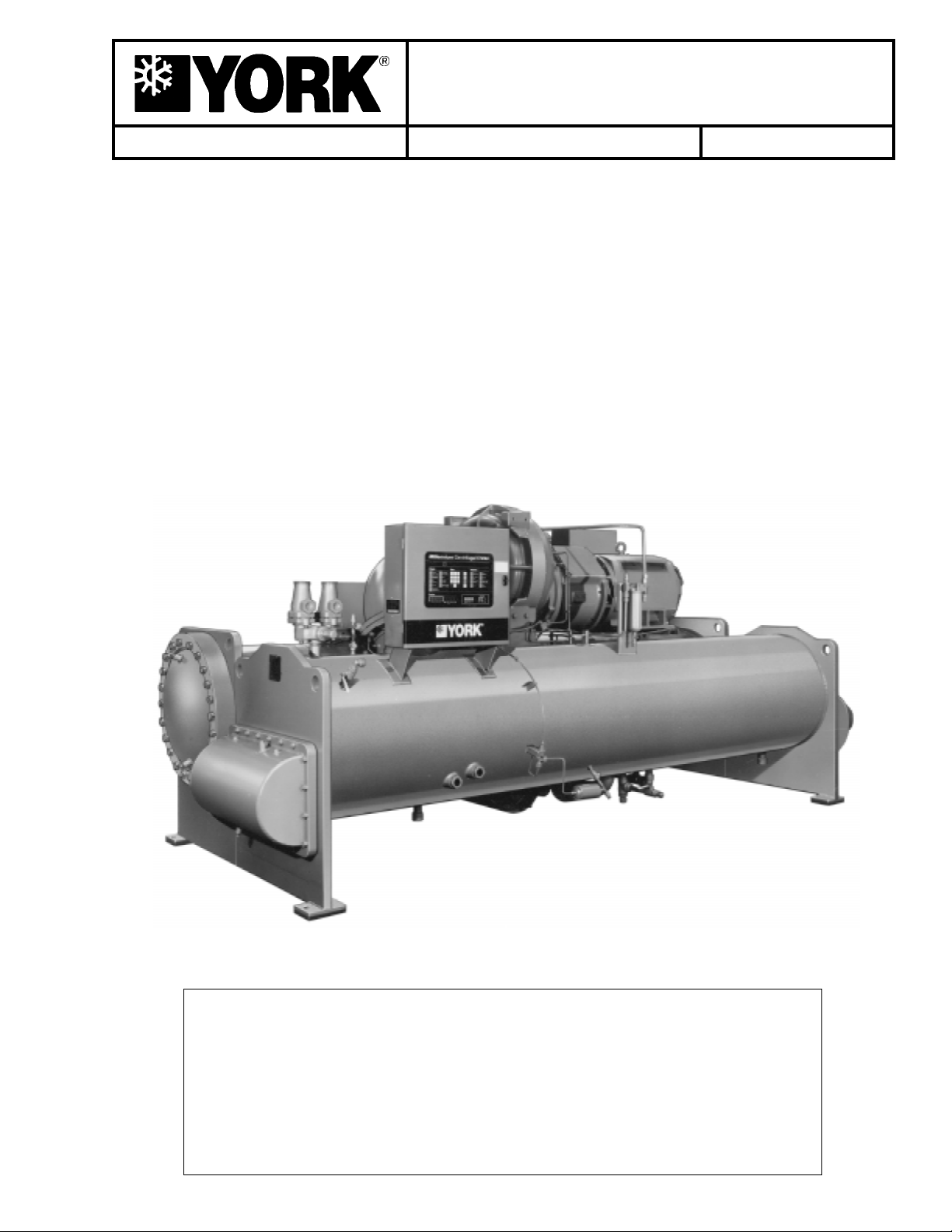
MILLENNIUM
TM
CENTRIFUGAL LIQUID CHILLERS
OPERATING & MAINTENANCE
MODEL YK M3 M3 G4 THRU YK S6 S4 J2 (STYLE C)
R-22 (COOLING ONLY)
MODEL YK LB LB G4 THRU YK SE SC J4 (STYLE C)
R-134a (COOLING ONLY)
WITH MICROCOMPUTER CONTROL CENTER
PART #371-01200-010, 371-01200-011 & 371-01200-015
FOR ELECTRO-MECHANICAL STARTER,
SOLID STATE STARTER & VARIABLE SPEED DRIVE
Supersedes: Nothing
Form 160.49-O2 (1296)
WW
ARNINGARNING
W
ARNING
WW
ARNINGARNING
SYSTEM CONTAINS REFRIGERANT UNDER PRESSURE.
SERIOUS INJURY COULD RESULT IF PROPER PROCEDURES ARE NOT
FOLLOWED WHEN SERVICING SYSTEM. ALL SERVICE WORK SHALL
BE PERFORMED BY A QUALIFIED SERVICE TECHNICIAN IN ACCORDANCE WITH Y ORK INSTALLATION/OPERA TION MANUAL.
27385A

TT
ABLE OF CONTENTSABLE OF CONTENTS
T
ABLE OF CONTENTS
TT
ABLE OF CONTENTSABLE OF CONTENTS
Page
SECTION 1 – Description of System and
Fundamentals of Operation ………………………………….. 4
SECTION 2 – MicroComputer Control Center ……………………………….. 6
SECTION 3 – System Operating Procedures ………………………………. 30
SECTION 4 – System Component Description ……………………………. 37
SECTION 5 – Operational Maintenance ……………………………………… 42
SECTION 6 – Trouble Shooting………………………………………………….. 44
SECTION 7 – Maintenance ……………………………………………………….. 49
SECTION 8 – Preventive Maintenance……………………………………….. 58
REFERENCE INSTRREFERENCE INSTR
REFERENCE INSTR
REFERENCE INSTRREFERENCE INSTR
DESCRIPTION FORM NO.
Solid State Starter – Operation & Maintenance 160.46-OM3.1
V ariable Speed Drive – Operation 160.00-O1
Installation 160.49-N5
Installation and Operation of Printers 160.49-N7
Wiring Diagram – Unit with Electro-Mechanical Starter 160.49-PW7
Wiring Diagram – Field Connections (E-M Starter) 160.49-PW10
Wiring Diagram – Field Control Modifications 160.49-PW13
Wiring Diagram – Control Center with SS Starter 160.49-PW8
Wiring Diagram – Field Connections (SS Starter) 160.49-PW11
Wiring Diagram – Solid State Starter 160.49-PW14
Wiring Diagram – Unit with Solid State Starter 160.49-PW8
Wiring Diagram – Unit with Variable Speed Drive 160.49-PW9
Wiring Diagram – Field Connections (V.S.D.) 160.49-PW12
Wiring Diagram – Variable Speed Drive 160.49-PW15
UCTIONSUCTIONS
UCTIONS
UCTIONSUCTIONS
2 YORK INTERNA TIONAL
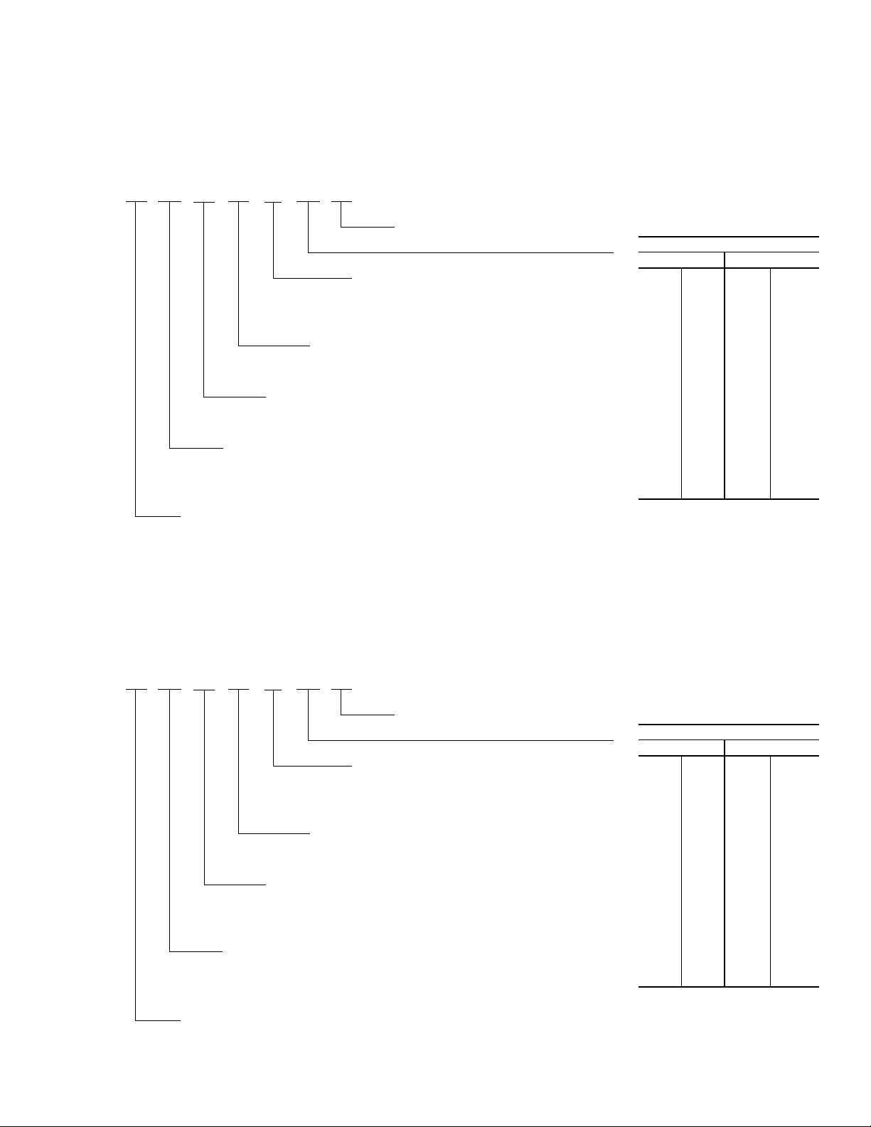
R-22 UNITS
YK N2 N1 H1 – CX C
CONDENSER CODE
M3, M4, N3, N4, P3, P4, Q3, Q4, R3, R4, S3, S4
COOLER CODE
M3, M4, N3, N4, P3, P4, P5, P6, Q3, Q4, Q5, Q6,
R3, R4, R5, R6, S5, S6
NOMENCLATURE
DESIGN LEVEL (C)
POWER SUPPLY
– for 60 HZ
5 for 50 HZ
COMPRESSOR CODE
G4, H0, H1, H2, J1, J2
FORM 160.49-O2
MOT OR CODE:
{
60 HZ 50 HZ
CH CX 5CE 5CT
CJ CY 5CF 5CU
CK CZ 5CG 5CV
CL CA 5CH 5CW
CM CB 5CI 5CX
CN DA 5CJ 5DA
CP DB 5CK 5DB
CR DC 5CL 5DC
CS DD 5CM 5DD
CT DE 5CN 5DE
CU DF 5CO 5OF
CV DH 5CP 5OG
CW DJ 5CQ 5OH
5CR 5OJ
5CS
MODEL
R-134a
YK NB PB H1 – CX C
CONDENSER CODE
LB, LC, MB , MC, NB, NC,
PB, PC, QB, QC, RB, RC, SB, SC
COOLER CODE
LB, LC, MB , MC , NB, NC, PB , PC, PD , PE,
QB, QC, QD, QE, RB, RC, RD , RE, SD, SE
DESIGN LEVEL (C)
POWER SUPPLY
– for 60 HZ
5 for 50 HZ
COMPRESSOR CODE
G4, H0, H1, H2, J1, J2, J3, J4
MOT OR CODE:
{
60 HZ 50 HZ
CH CX 5CE 5CT
CJ CY 5CF 5CU
CK CZ 5CG 5CV
CL CA 5CH 5CW
CM CB 5CI 5CX
CN DA 5CJ 5DA
CP DB 5CK 5DB
CR DC 5CL 5DC
CS DD 5CM 5DD
CT DE 5CN 5DE
CU DF 5CO 5DF
CV DH 5CP 5DG
CW DJ 5CQ 5DH
5CR 5OJ
5CS
MODEL
Y ORK INTERNA TIONAL 3
CONTROL
CENTER
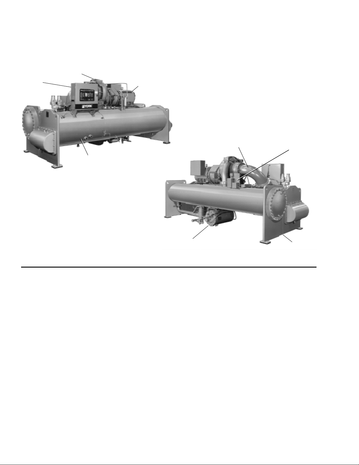
SECTION 1
DESCRIPTION OF SYSTEM AND FUNDAMENTALS OF OPERA TION
COMPRESSOR
MOTOR
PRE-ROT ATION
DISCHARGE LINE
27385A
COOLER
VANE
ACTUA T OR
FIG. 1 – MODEL YK MILLENNIUM CHILLER
SYSTEM OPERATION DESCRIPTION (See Fig. 2)
The YORK Model YK Millennium Chiller is commonly
applied to large air conditioning systems, but may be
used on other applications. The chiller consists of an
open motor mounted to a compressor (with integral
speed increasing gears) condenser, cooler and flow
control chamber.
The chiller is controlled by a modern state of the art
MicroComputer Control Center which monitors its operation. The Control Center is programmed by the operator to suit job specifications. Automatic timed startups and shutdowns are also programmed to suit
nighttime, weekends, and holidays. The operating status, temperatures, pressures, and other inf ormation pertinent to operation of the chiller are automatically displayed and read on a 40 character alphanumeric
message display. Other displays can be observed by
pressing the keys as labeled on the Control Center.
The chiller with the MicroComputer Control Center is
applied with an electro-mechanical starter, YORK Solid
State Starter (optional), or Variable Speed Drive (optional).
OIL RESERVOIR/
PUMP
CONDENSER
In operation, a liquid (water or brine to be chilled) flows
through the cooler, where boiling refrigerant absorbs
heat from the water. The chilled liquid is then piped to
fan coil units or other air conditioning terminal units,
where it flows through finned coils, absorbing heat from
the air. The warmed liquid is then returned to the chiller
to complete the chilled liquid circuit.
The refrigerant vapor, which is produced by the boiling
action in the cooler, flows to the compressor where the
rotating impeller increases its pressure and temperature and discharges it into the condenser. W ater flowing
through the condenser tubes absorbs heat from the refrigerant vapor, causing it to condense. The condenser
water is supplied to the chiller from an external source,
usually a cooling tower . The condensed refrigerant drains
from the condenser into the flow control chamber, where
the flow restrictor meters the flow of liquid refrigerant
to the cooler to complete the refrigerant circuit.
The major components of a chiller are selected to handle
the refrigerant which would be evaporated at full load
27382A
4 YORK INTERNA TIONAL

7619A(D)
DET AIL A – COMPRESSOR PRER O TATION V ANES
FORM 160.49-O2
design conditions. Howev er, most systems will be called
upon to deliver full load capacity for only a relatively
small part of the time the unit is in operation.
CAPACITY CONTROL
The major components of a chiller are selected for full
load capacities, therefore capacity must be controlled to
maintain a constant chilled liquid temperature leaving
the cooler. Prerotation vanes (PRV), located at the entrance to the compressor impeller, compensate f or variation in load (See Fig. 2. Detail A).
The position of these vanes is automatically controlled
through a lever arm attached to an electric motor located outside the compressor housing. The automatic
adjustment of the vane position in effect provides the
performance of many different compressors to match
various load conditions from full load with vanes wide
open to minimum load with vanes completely closed.
COMPRESSOR
DISCHARGE
DISCHARGE
BAFFLE
CONDENSER
SUB-COOLER
FLOW CONTROL
ORIFICE
PREROT A TION V ANES
(See Detail A)
SUCTION
COOLER
ELIMINA TOR
LD00924
FIG. 2 – REFRIGERANT FLOW-THRU CHILLER
Y ORK INTERNA TIONAL 5
OIL COOLER
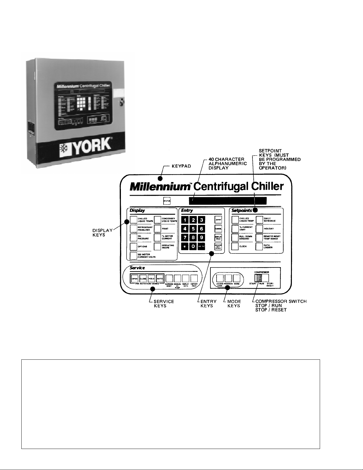
SECTION 2
MICROCOMPUTER CONTROL CENTER
26879A
LD00953
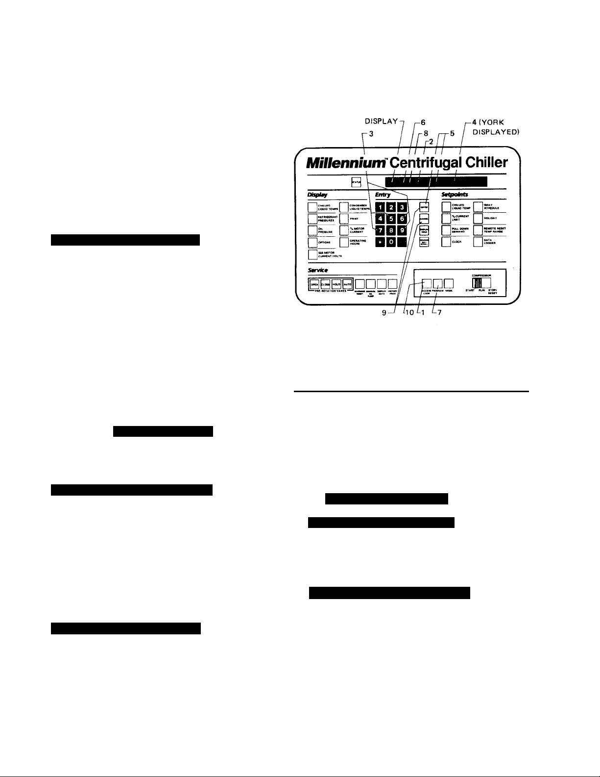
FIG. 3 – MICROCOMPUTER CONTR OL CENTER AND KEYPAD
NOTE: This instruction covers operation of chillers equipped with Electro-Mechanical or Solid State Starters. If chiller
is equipped with Variable Speed Drive, Form 160.00-O1 is to be used in conjunction with this manual.
WARNING
This equipment generates, uses and can radiate radio frequency energy and if not installed and used in accordance with the instructions manual, may cause interference to radio communications . Operation of this equipment in a residential area is likely to cause interference in which case the user at his own expense will be
required to take whatev er action ma y be required to correct the interf erence .
Additionally , any electronic equipment can generate EMI (electromagnetic interf erence) which, depending upon
the installation and magnitude, may affect other electronic equipment. The amount of EMI generated is determined by the source inductance, load inductance, and circuit impedances. Responsibility for assuring the
satisfactory operation of other equipment included in the same power source as the YORK equipment rests
solely with the user. YORK disclaims any liability resulting from any interference or for the correction thereof.
6 YORK INTERNA TIONAL

INTRODUCTION
FORM 160.49-O2
The YORK MicroComputer Control Center is a microprocessor based control system for R-22 or R134a centrifugal chillers. It controls the lea ving chilled water temperature via pre-rotation vane control and has the ability
to limit motor current via control of the pre-rotation vanes.
Further, it is compatible with YORK Solid State Starter
(optional), Variable Speed Drive (optional), and electromechanical starter applications.
A keypad mounted on the front of the Control Center
(see Fig. 3) allo ws the operator to displa y system operating parameters on a 40 character alphanumeric display that is part of the keypad. These readings are displayed via “Display” keypad as follows: (In the English
mode; temperatures in °F, pressures in (PSIG) (in the
metric mode, temperatures in °C, Pressures in KP a).
If unit is equipped with EPROM version C.02F(T).12 or
later, the Control Center can be equipped with an optional Chinese language display, either as a field retrofit
or factory supplied option on new units. This display
mounts on the control center door, directly above the
standard display. Both the standard and Chinese display will be present, providing displa y messages simultaneously in both English and Chinese language.
The system setpoints (see Fig. 3) are operator entered
on the front control center Setpoints keypad. These
setpoints can also be displayed on the 40 char acter alphanumeric display. The system setpoints are:
• CHILLED LIQUID TEMPERATURE (LCWT)
• % CURRENT LIMIT
• PULLDOWN DEMAND LIMIT
• CLOCK (TIME-OF-DAY)
• DAILY SCHEDULE (7 DAY TIME-CLOCK PROGRAMMING)
• HOLIDAY
• REMOTE RESET TEMPERATURE RANGE
• DATA LOGGER
• CONDENSER REFRIGERANT LEVEL
The cause of all system shutdowns (safety or cycling) is
preserved (until the system is reset or restarts) in the
microcomputer’s memory for subsequent viewing on the
keypad display. The operator is continually advised of
system operating conditions by various background and
warning messages. The keypad contains special service keys for use by the service technician when performing system troubleshooting.
The Control Center must be configured for Chinese display by a qualified service technician. Instructions are
contained in YORK service manual, Form 160.49-M3.
• CHILLED LIQUID TEMPERATURES – LEAVING AND
RETURN
• REFRIGERANT PRESSURES – EVAPORATOR AND
CONDENSER
• DIFFERENTIAL OIL PRESSURE
• CONDENSER LIQUID TEMPERATURES – OPTIONAL
FIELD INSTALLED – LEAVING AND RETURN
• OPTIONS
• PRINT *
• HISTORY PRINT *
• MOTOR CURRENT IN % OF FULL LOAD AMPS
• SA TURA TION TEMPERA TURES – EV APORATOR AND
CONDENSER
• DISCHARGE TEMPERATURE
• OIL TEMPERATURE
• HIGH & LOW OIL PRESSURE TRANSDUCER PRESSURE
• SOLID ST ATE STARTER MOTOR CURRENT / VOLTS
(When Supplied)
• CONDENSER REFRIGERANT LEVEL
The MicroComputer Control Center is designed to be
compatible with most Energy Management Systems
(EMS) in use today. The standard design allows for the
following EMS interface:
1. Remote Start
2. Remote Stop
3. Remote LCWT Setpoint (Pulse Width Modulated signal)
4. Remote Current Limit Setpoint (Pulse Width Modulated
signal)
5. A “Remote Mode Ready to Start” Status Contacts
6. Safety Shutdown Status Contacts
7. Cycling Shutdown Status Contacts
As an enhancement to the standard EMS features, an
optional card file with plug-in printed circuit boards is
available. These optional cards will accept a remote
LCWT 0 to 10°F or 0 to 20°F setpoint offset and/or remote current limit setpoint interface from three user input choices.
1. 4-20mA
2. 0-10VDC
* These ke ys provide a print-out when the customer connects a com-
patible printer to the Micro Board RS-232 serial port. (See Form
160.49-N7.)
Y ORK INTERNA TIONAL 7
3. Contact Closures

CONTROL CENTER
The Control Center front panel layout consists of five
key groups, one switch and a 1 line by 40 character alphanumeric vacuum fluorescent display: (see Fig. 3.)
CHARACTERISTIC DISPLAY – The alphanumeric
vacuum fluorescent display is located to the right of the
ST ATUS key . All messages, parameters, set points, and
data can be viewed at this location. The main communications between the operator or service technician and
the MicroComputer Control Center occurs on this display.
DISPLAY – Provide a direct readout of each monitored
parameter on the alphanumeric display.
ENTRY – These keys are used to enter the values for
the operator programmed setpoints. These k eys are used
in conjunction with the Setpoint keys while in PRO-
GRAM mode.
SETPOINTS – These keys are used as follows:
1. To view each setpoint, in any mode , or
2. To select the individual setpoints that are prog rammed
by the operator in PR OGRAM mode only.
Pressing the appropriate key enables the operator to
program that setpoint pressing the Entry keys.
SERVICE– Included in this group of keys are those functions that are only relevant to servicing the chiller .
Typically, these keys would not be used for daily chiller
operation.
ACCESS CODE – Permits operator to access the program.
PROGRAM – Permits operator to program the Control
Center.
MODE – P ermits operator to check what mode the Control Center is presently in (LOCAL, REMOTE or SER-
VICE).
1. Service – allows manual PRV control with visual
display readout of PRV operation.
2. Local – allows manual compressor start from the
COMPRESSOR switch on the Control Center front.
3. Program – allows operator programming of system
setpoints.
4. Remote – allows remote start, remote stop of compressor and remote reset of LCWT and % current
limit.
COMPRESSOR-START, RUN, STOP/RESET
SWITCH – This 3-position rocker s witch is used to start
(except in REMO TE mode), stop/run/reset the system.
OPERATION
DISPLA YING SYSTEM PARAMETERS
The Display keys are used to display selected
monitored parameters as follows: (Refer to Fig. 3.)
• Press and release the appropriate Display ke y – the
message will be displayed f or 2 seconds.
– or –
• Press and hold the appropriate Display key – the message will be displayed and updated every 0.5 seconds until the Display ke y is released.
– or –
• Press and release appropriate Display key , then press
and release the DISPLAY HOLD key – the message
8 YORK INTERNA TIONAL
will be displayed and updated every 2 seconds until
the DISPLAY HOLD key is again pressed and re-
leased, or 10 minutes have elapsed, whiche ver comes
first.
NOTE: If the display actually displays X’s, then the
monitored parameter is out of normal operating range (refer to Fig. 4). If the “English/Metric”
jumper is installed on the Micro Board, all temperatures are displayed in degrees F ahrenheit
(°F) and all pressures are displayed in pounds
per sq. inch gauge (PSIG) except oil pressure
which is displayed in pounds per sq. inch diff erential (PSID). If the “English/Metric” jumper is
not installed, all temperatures are displayed in
degrees Centigrade (°C) and all pressures are
displayed in Kilo-Pascals (kPa).

FORM 160.49-O2
DISPLAY
READS
CONDENSER PRESS. = < 6.8 PSIG, or > 300 PSIG XX.X PSIG
EVAPORATOR PRESS. = < 50 PSIG, or > 125 PSIG XX.X PSIG
EVAP. PRESS. (BRINE) = < 25 PSIG, or > 100 PSIG XX.X PSIG
HOP TRANSDUCER = < 59.1 PSIG, or > 314.9 PSIG XX.X PSIG
LOP TRANSDUCER = < 23.2 PSIG, or > 271.8 PSIG XX.X PSIG
DISCHARGE TEMP. = < 20.3°F; > 226.4°F XXX.X°F
OIL TEMP. = < 20.3°F; > 226.4°F XXX.X°F
LEAVING CONDENSER
WATER TEMP.
ENTERING CONDENSER
WATER TEMP.
LEAVING EVAPORATOR = < 0°F XX.X°F
WATER TEMP. = > 81.1°F XX.X°F
ENTERING EVAPORATOR = < .1°F XX.X°F
WATER TEMP. = > 93°F XX.X°F
= < 8.4°F; > 134.1°F XXX.X°F
= < 8.4°F; > 134.1°F XXX.X°F
FIG. 4 – SYSTEM PARAMETERS – OUT OF
RANGE READINGS
To Display CHILLED LIQUID TEMPERATURES:
______ PSID = (HOP – LP) – OFFSET PRESSURE
OFFSET PRESSURE: Pressure differential between
the HOP transducer and LOP transducer outputs during a 3 second period beginning 10 seconds after the
start of “START SEQUENCE INITIATED”. During this
time, the transducers will be sensing the same pressure and their outputs should indicate the same pressure. However, due to accuracy tolerances in transducer design, differences can exist. Therefore, to compensate for differences between transducers and assure differential pressure sensing accuracy, the OFF-
SET PRESSURE is subtracted algebraically from the
differential pressure. The offset pressure calculation
will not be performed if either transducer is out-of-range.
The offset value will be taken as 0 PSI in this instance.
To Display OPTIONS:
This key is not used.
NO OPTIONS INSTALLED
is displayed when this key is pressed.
Press CHILLED LIQUID TEMPS displa y key as de-
scribed on page 7 to produce the following alphanumeric display message:
CHILLED LEA VING = XXX.X°F, RETURN = XXX.X°F
To Display REFRIGERANT PRESSURE:
Use REFRIGERANT PRESSURE display key as
described on page 7 to produce the following alphanumeric display message:
EV AP = XXX.X PSIG; COND = XXX.X PSIG
To Display OIL PRESSURE:
Use OIL PRESSURE display key as described on
page 7 to produce the following alphanumeric display message:
OIL PRESSURE = XXXX.X PSID
The differential pressure displayed is the pressure difference between the high side oil pressure transducer
(output of oil filter) and the low side oil pressure transducer (compressor housing). Displayed value includes
offset pressure derived from auto-zeroing during
“START SEQUENCE INITIATED”. If either transducer
is out-of-range, XX.X is displayed. Oil pressure is
calculated as follows:
To Display SSS MOT OR CURRENT / VOLTS:
(Solid State Starter Applications Only)
If chiller is equipped with a Y ORK Solid State Starter,
use SSS MOTOR CURRENT / VOLTS key to dis-
play 3-phase compressor motor current and 3-phase
Solid State Starter input line voltage.
Continuously pressing this key will display the motor current and line voltage alternately. When used
with the DISPLAY HOLD key, motor current and
line voltage will alternately be displayed each time
this key is pressed. The messages are as follows:
A AMPS = XXXX; B AMPS = XXXX; C AMPS = XXXX
V A-B = XXXX; V B-C = XXXX; V C-A = XXXX
If chiller is not equipped with a Solid State Starter,
this key produces the following message:
SOLID STATE STARTER NOT INSTALLED
In PROGRAM mode, this k ey is used to displa y the
applicable line voltage range (200-208VAC, 220240V AC , 380VAC, 400V A C , 415V A C , 440-480V A C,
500-600V AC, Supply V oltage Range Disab led). The
correct line voltage range is programmed at the
YORK factory and is checked by the service technician at start-up. For security reasons, a special
access code is required to program the line voltage range. The line voltage range is used to determine a low line voltage threshold for cycling shutdown. Refer to “System Setpoints” for Trip/Reset
values.
Y ORK INTERNA TIONAL 9

To Display CONDENSER LIQUID TEMPERATURES
(Field Installed Option Package):
Use CONDENSER LIQUID TEMPS display key as
described above to produce the follo wing alphan umeric display message:
Computer Control Center”, page 14. However,
the purpose of the OPERATING HOURS key
is to display the total accumulated chiller run
time. Therefore, the operating hours should not
be arbitrarily reset.
SYSTEM SETPOINTS
COND LEAVING = XXX.X°F; RETURN = XXX.X°F
NOTE: If the condenser liquid thermistors are not con-
nected, or both thermistors are “out of range”,
the display will blank when this k e y is pressed.
To Initiate a PRINT to Printer:
Press the PRINT key to initiate a printout to an optional printer. When the key is pressed,
PRINT ENABLE
is displayed.
Refer to “MicroComputer Control Center – System
Status Printers” instruction, Form 160.49-N7 for details of the optional printers.
To Display MOTOR CURRENT:
Press the % MOTOR CURRENT display key as
described above to display motor current as a percent of Full Load Amps (FLA). The message is as
follows:
MOTOR CURRENT = XXX% FLA
The system setpoints may be programmed by the system operator. The Setpoints keys are located on the
Control Center keypad (see Fig. 3). To program, see “Programming System Setpoints”, page 14. The following
is a description of these setpoints (with the English/
Metric jumper installed on the Micro Board):
CHILLED LIQUID TEMP – This key displays the leaving chilled water temperature (LCWT) setpoint in degrees
Fahrenheit. If not progr ammed, the default value is 45°F.
See “Programming System Setpoints”, page 15).
NOTE: If an Energy Management System is interfaced
to the Control Center for the purpose of remote
LCWT setpoint reset, then the operator-programmed chilled liquid temperature will be the
base or lowest setpoint av ailable to the Energy
Management System (EMS). This chilled liquid
temperature value must also be entered into the
EMS. Further, any subsequent change to this
value must also be entered into the EMS.
% CURRENT LIMIT – This key displays the maximum
value of motor current permitted by its programmed setting. The value is in terms of percent of Full Load Amps
(FLA). If not programmed, the def ault value is 100%. (See
“Programming System Setpoints”, page 15.)
NOTE: • Liquid-Cooled Solid State Starter Applications
– the % Motor Current displayed is the highest
of three line currents divided by the programmed
chiller FLA value x 100%.
• Electro-Mechanical Starter Applications – the
% Motor Current displayed is the highest of the
three line currents.
If chiller is equipped with a YORK Solid State Starter,
the system FLA is also displayed. This value is programmed by the f actory and should nev er be changed.
The Micro Board uses this value to calculate and display the % motor current parameter that is displayed
when the % MOT OR CURRENT display ke y is pressed.
Also, proper current limit control depends on the correctly programmed FLA value. For security reasons, a
special access code is required to program the FLA value.
It should only be changed by a service technician.
To Display OPERATING HOURS and STARTS
COUNTER:
Use the OPERA TING HOURS ke y as described on
page 8, to produce the following message:
OPER. HOURS = XXXXX; START COUNTER = XXXXX
PULL DOWN DEMAND – This function is used to provide energy savings following the chiller start-up. This
key displays a programmable motor current limit and a
programmable period of time. Operation is as follows:
Whenever the system starts, the Pull Down Demand
Limit is maintained for the programmed time, then the
current limit control returns to % current limit setpoint.
NOTE: The operating hours and starts counter can be
reset to zero. Ref er to “Progr amming the Micro-
The maximum permitted motor current is in terms of %
FLA. The duration of time that the current is limited is in
10 YORK INTERNA TIONAL

FORM 160.49-O2
terms of minutes (to a maximum of 255). If not programmed, the default value is 100% FLA for 00 minutes. (See “Programming Systems Setpoints”, page 16.)
Thus, no pull down demand limit is imposed following
system start, and the % current limit setpoint is used.
CLOCK – This key displa ys the day of the week, time of
day and calendar date. If not programmed, the default
value is
SUNDAY 12:00 AM 1/1/92 .
(See “Programming System Setpoints”, page 16.)
DAIL Y SCHEDULE – This key displays the programmed
daily start and stop times, from Sunday thru Saturday
plus Holiday. If desired, the Control Center can be programmed to automatically start and stop the chiller as
desired. This schedule will repeat on a 7-day calendar
basis. If the Daily Schedule is not progr ammed, the default value is 00:00 AM start and stop times for all da ys
of the week and the holiday. (Note that the system will
not automatically start and stop on a daily basis with
these default values because 00:00 is an “Impossible”
time for the Micro Board. See “Programming System
Setpoints”, page 17.) Finally, one or more days in the
week can be designated as a holiday (see description
under HOLIDAY setpoint) and the Control Center can
be programmed (usually Daily Schedule setpoint) to
automatically start and stop the chiller on those days so
designated. The operator can override the time clock
at any time using the COMPRESSOR switch.
For additional information on remote LCWT reset, refer
to Form 160.49-PW13.
NOTE: If an Energy Management System is interfaced
to the Control Center for the purpose of remote
LCWT setpoint reset, then the operator programmed REMOTE RESET TEMP RANGE
value determines the maximum value of temperature reset controlled by the Energy Management System.
DATE LOGGER – This key is used when an optional
printer is connected to the MicroComputer Control Center. Refer to Form 160.49-N7 for operation instructions.
SSS MOT OR CURRENT/VOLTS – This key is used on
Solid State Starter applications only. Although this is a
display key, it is used to program the applicable AC
power line voltage range (380VAC, 400VAC, 415VAC,
440-480VAC, 550-600VAC). The MicroComputer Control Center uses this entry to determine the under-voltage and overvoltage shutdown threshold. For each
line voltage category, there is an undervoltage and overvoltage shutdown threshold. If the AC po wer line v oltage exceeds these thresholds for 20 continuous seconds, the chiller shuts down and displays
MON 10:00 AM LOW LINE VOLTAGE
– or –
Note that if only a start time is entered for a particular
day, the compressor will not automatically stop until a
scheduled stop time is encountered on a subsequent
day.
HOLIDAY – This key indicates which da ys in the upcoming week are holidays. On those designated days, the
chiller will automatically start and stop via the holiday
start and stop times programmed in the DAIL Y SCHED-
ULE setpoint. It will do this one time only and the f ollowing week will rev ert to the normal daily schedule for that
day.
REMOTE / RESET TEMP RANGE – This key displays
the maximum offset of remote LCWT setpoint reset. This
offset is either 10° or 20°F as programmed. When in the
REMOTE mode, this v alue is added to the operator programmed CHILLED LIQUID TEMP setpoint and the sum
equals the temperature range in which the LCWT can
be reset. For example, if the operator programmed
CHILLED LIQUID TEMP setpoint is programmed with a
value of 10°F, then the CHILLED LIQUID TEMP setpoint
can be remotely reset over a range of 46°F to 56°F (46
+ 10 = 56). If not prog rammed, the default value for this
parameter is 20°F.
MON 10:00 AM HIGH LINE V OLTAGE
This overvoltage and undervoltage protection can be
disabled. Ref er to chart below:
LOW / HIGH LINE VOLTAGE TRIP / RESET VALUES
COMPRESSOR
MOT OR
SUPPL Y VOL TA GE
RANGE – (V)
380 305 331 415 414
400 320 349 436 435
415 335 362 454 453
440-480 370 400 524 523
550-600 460 502 655 654
Supply V oltage
Range Disabled
LOW LINE VOL TAGE HIGH LINE V O LTAGE
OPERA TING POINT OPERATING POINT
CUTOUT -(V) CUTIN-(V) CUTOUT -(V) CUTIN-(V)
(
ON FALL) (ON RISE) (ON RISE) (ON FALL)
NONE 0 NONE 0
For security reasons, a special access code is required
to program the supply voltage range. The supply voltage
range is programmed at the factory and should only be
changed by a service technician.
Y ORK INTERNA TIONAL 11

DISPLAYING SYSTEM SETPOINTS
The currently programmed Setpoint values can be
viewed at any time (see page 22) in SER VICE, LOCAL
or REMOTE operating mode as follo ws:
• Press and release the appropriate Setpoint key – the
message will be displayed f or 2 seconds.
– or –
If chiller is equipped with a YORK Solid State Starter,
the message is:
CURRENT LIMIT = XXX % FLA; *MTR CUR = 000 FLA
NOTE: On Solid State Starter applications, this value is
programmed at the YORK factory . A special access code is required.
• Press and hold the appropriate Setpoint key – the
message will be displayed as long as the key is
pressed.
– or –
• Press and release the appropriate Setpoint key , then
press and release the DISPLA Y HOLD k ey . The message will be displayed until the DISPLAY HOLD key is
again pressed and released, or 10 minutes have
elapsed, whichever comes first.
To Display CHILLED LIQUID TEMP Setpoint:
Use CHILLED LIQUID TEMP setpoint key as de-
scribed on page 10 to produce the following message:
LEAVING SETPOINT = XX.X °F
NOTE: The value displayed is the actual LCWT setpoint.
For example , the value display ed in LOCAL
or
PROGRAM modes is that which is oper ator programmed. The v alue displayed in the REMOTE
mode is that base setpoint with added temperature reset by an Energy Management System,
via remote LCWT setpoint (PWM signal) if a remote reset signal was received within 30 minutes.
To Display PULL DOWN DEMAND Setpoint:
Use PULL DOWN DEMAND setpoint key as de-
scribed on page 10 to produce the following message:
SETPOINT = XXX MIN @ XX % FLA XXX MIN LEFT
To Display CLOCK Setpoint (Time of Day):
Use CLOCK setpoint key as described above to
produce the following message:
TODAY IS DAY XX:XX AM/PM 1/1/92
To Display DAILY SCHEDULE Setpoints:
• Press and hold the DAILY SCHEDULE setpoint key.
The chiller start and stop times for each day of the
week are sequentially display ed, beginning with Sunday and ending with Holida y. The displa y will continuously scroll until the DAILY SCHEDULE key is re-
leased.
– or –
• Press and release the DAIL Y SCHEDULE setpoint k ey .
Then press and release the DISPLA Y HOLD k ey . The
To Display % CURRENT LIMIT Setpoint:
Use % CURRENT LIMIT setpoint key as described
above to produce the f ollowing message:
CURRENT LIMIT = XXX % FLA
chiller start and stop times for each day of the week
are sequentially displayed beginning with Sunda y and
ending with Holiday . The display will continuously scroll
until the DISPLAY HOLD key is again pressed and
released, or 10 minutes have elapsed, whichever
comes first.
NOTE: The value display ed is the actual % current limit
setpoint. For example, the value displayed in
LOCAL or PROGRAM mode is that which is
operator programmed. The value displayed in
the REMOTE mode is that which has been pro-
grammed by the Energy Management System
via the remote current limit setpoint input.
The display message for DAILY SCHEDULE will scroll
in the following sequence:
SUN START = 08:30 AM STOP = 06:00 PM
MON START = 05:00 AM STOP = 07:00 PM
12 YORK INTERNA TIONAL

TUE START = 05:00 AM STOP = 07:00 PM
FORM 160.49-O2
WED START = 05:00 AM STOP = 07:00 PM
THU START = 05:00 AM STOP = 07:00 PM
FRI START = 05:00 AM STOP = 07:00 PM
SAT STAR T = 05:00 AM STOP = 01:00 PM
HOL START = 00:00 AM STOP = 00:00 PM
To Display HOLIDAY Setpoints:
Use HOLIDAY setpoint key as described in the be-
ginning of this section to produce the following message:
S_ M_ T_ W_ T_ F_ S_ HOLIDAY NOTED BY *
NOTE: On the days that are designated by an *, the
chiller will automatically start and stop per the
holiday schedule established in D AIL Y SCHED-
ULE setpoints.
To Display UNDERVOLTAGE setpoints:
(Solid State Starter Applications Only)
Press SSS MOTOR CURRENT/V OL TS key in PRO-
GRAM mode to display the selected voltage range.
One of the following messages will be displa yed.
SUPPLY VOLTAGE RANGE 380
– or –
SUPPLY VOLTAGE RANGE 400
– or –
SUPPLY VOLTAGE RANGE 415
– or –
SUPPLY VOLTAGE RANGE 440-480
– or –
SUPPLY VOLTAGE RANGE 550-600
– or –
To Display REMOTE RESET TEMP RANGE Setpoint:
Use REMOTE RESET TEMP RANGE setpoint ke y
as described above to produce the following message:
REMOTE RESET TEMP RANGE = 10°F
– or –
REMOTE RESET TEMP RANGE = 20°F
To Display DATA LOGGER setpoints:
Refer to Y ORK, F orm 160.49-N7 for operation of this
key .
SUPPLY VOLTAGE RANGE DISABLED
A special access code is required to program the Supply Voltage Range. The Supply Voltage Range is programmed at the factory and check ed at system start-up.
(Note to service technician: Refer to programming instructions in Service Instruction, Form 160.49-M3.)
Y ORK INTERNA TIONAL 13
PROGRAMMING
THE MICROCOMPUTER CONTROL CENTER
PROGRAMMING SYSTEM SETPOINTS
The system setpoints can be entered at any time . . . . .
even when the system is running. Proceed as f ollows to
enter system setpoints. (Ref er to Fig. 5.)
1. Press ACCESS CODE key .
2.
ENTER VALID ACCESS CODE _ _ _ _
3. Using ENTRY keys, enter 9 6 7 5.
4. As each digit is entered, the characters Y O R K are
displayed.
is displayed.
NOTE: If digits other than 9 6 7 5 are entered,
YORKis still displayed.
NOTE: For ease in remembering the code, note that
the letters YORKcorrespond to the digits 9675on a telephone dial
.
5. Press ENTER key.
NOTE: If digits other than 9675 w ere entered in step
No. 4,
INVALID ACCESS CODE
is displayed
when the ENTER key is pressed. If this occurs, enter the correct access code (9675)
and proceed.
6.
ACCESS TO PROGRAM KEY AUTHORIZED
is displayed.
NOTE: Unless terminated by pressing the ACCESS
CODE key again, the operator will have access to the PROGRAM key for 10 minutes.
When 10 minutes have elapsed, access to
PROGRAM key will be automatically disab led
and the operator must return to step No. 1 to
gain access.
7. Press PROGRAM key .
8.
PROGRAM MODE, SELECT SETPOINT
is displayed.
LD00954
FIG. 5 – KEYPAD – PROGRAMMING SYSTEM
SETPOINTS
9. Enter setpoints as detailed below. If you make a mistake when entering a value, press CANCEL k ey and
then ENTER key . The display will re vert to the default
values and the cursor will return to the first changeable digit. You can then proceed to enter the correct
values. If the entered v alue exceeds acceptab le limits,
OUT OF RANGE – TRY AGAIN!
message will be displayed for 2 seconds, then the
PROGRAM MODE, SELECT SETPOINT
message will re-
appear.
10.When all the desired setpoints have been entered,
press the ACCESS CODE key to exit PROGRAM
mode and terminate access to PROGRAM mode.
ACCESS TO PROGRAM MODE DISABLED
is displayed.
The Control Center will automatically return to LO-
CAL, REMOTE or SERVICE mode . . . . whichever
was last selected.
14 YORK INTERNA TIONAL
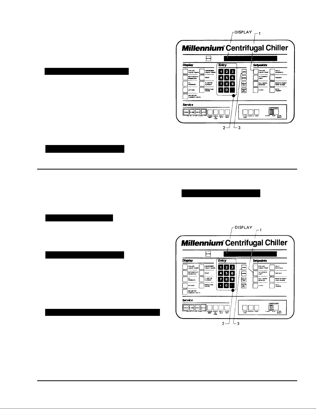
To enter CHILLED LIQUID TEMP Setpoint: (Refer to
Fig. 6.)
1. Press and release CHILLED LIQUID TEMP setpoint
key. The following program prompt message will be
displayed:
LEAVING SETPOINT = XX.X °F (BASE)
(BASE) refers to the base or lowest setpoint available to an Energy Management System. If an y Energy Management System is applied, this value must
be entered into the Energy Management System.
Refer to previous explanation or REMO TE/RESET
TEMP RANGE, page 11.
FORM 160.49-O2
2. Use ENTRY keys to enter desired v alue.
3. Press and release ENTER key.
PROGRAM MODE, SELECT SETPOINT
message is displayed.
To Enter % CURRENT LIMIT Setpoint:
(Electro-Mechanical Starter , ref er to Fig. 7)
1. Press and release % CURRENT LIMIT setpoint key .
The following program prompt message is displa yed:
CURRENT LIMIT = XXX% FLA
2. Use ENTRY k e ys to enter desired v alue .
3. Press and release ENTER key.
PROGRAM MODE, SELECT SETPOINT
message is displayed.
LD00955
FIG. 6 – KEYPAD – PROGRAMMING “LEAVING
CHILLED WATER TEMP” SETPOINT
3. Press and release ENTER key.
PROGRAM MODE, SELECT SETPOINT
message is displayed.
(Solid State Starter, ref er to Fig. 7)
1. Press and release % CURRENT LIMIT setpoint key .
The following program prompt message is displa yed:
CURRENT LIMIT = XXX% FLA; MTR CUR = _ _ _ FLA
2. Use ENTRY k e ys to enter desired v alue .
NOTE: Motor Current FLA value is entered by Y ORK
LD00956
factory and checked at system start-up. It
cannot be changed without special access
code. (Note to service technician: refer to
FIG. 7 – KEYPAD – PROGRAMMING “% CURRENT
LIMIT” SETPOINT
“Programming Instructions” in Service instruction, Form 160.49-M3.
Y ORK INTERNA TIONAL 15

To Enter PULL DOWN DEMAND Setpoint:
(Refer to Fig. 8.)
1. Press and release PULL DOWN DEMAND setpoint
key. The following program prompt message is displayed:
SETPOINT = XXX MIN @ XXX % FLA, XXX MIN LEFT
2. Use Entry keys to enter desired values. For explanation, see PULL DOWN DEMAND, page 12. Note
that “XX min left” is not an operator entered v alue .
3. Press and release ENTER key.
PROGRAM MODE, SELECT SETPOINT
message is displayed.
LD00957
FIG. 8 – KEYPAD – PROGRAMMING “PULL DO WN
DEMAND” SETPOINT
To Enter CLOCK Setpoint: (Refer to Fig. 9.)
1. Assure Micro Board Program jumper J57 is in
“CLKON” position.
2. Press and release CLOCK setpoint key. The f ollo w-
ing program prompt message is displayed:
TOD AY IS MON 10:30 PM 1/1/92
3. Press ADVANCE DAY / SCROLL key until the pro-
gram per day of week appears on the display.
4. Use Entry keys to enter proper time of day.
5. Press AM/PM key to change the AM to PM or vice
versa.
6. Use Entr y keys to enter proper calendar date,
(MONTH/DA Y/YR). If month and da y are single digit
entries, precede the entry with “0”. For example,
02/04/88.
7. Press and release ENTER key.
PROGRAM MODE, SELECT SETPOINT
message is displayed.
LD00958
FIG. 9 – KEYPAD – PROGRAMMING “CLOCK”
SETPOINT
16 YORK INTERNA TIONAL

FORM 160.49-O2
To Enter DAILY SCHEDULE Setpoint:
(Refer to Fig. 10.)
1. Press and release DAILY SCHEDULE setpoint key.
The following prompt message is displa yed:
SUN START = XX:XX AM, STOP = XX:XX AM
2. If the displayed start and stop time is not the desired
schedule, enter the desired start and stop times as
follows:
a. If you do not want the chiller to automatically start
and stop on this day, press CANCEL key.
b. Use the Entry keys to enter desired hours and
minutes start time.
c. If necessary, press the AM/PM ke y to change “AM”
to “PM” or vice versa.
d. Use the Entry keys to enter desired hours and
minutes stop time.
e. If necessary , press the AM/PM key to change “AM”
to “PM” or vice versa.
3. Press and release ADV ANCE D A Y/SCROLL ke y. The
following prompt message is displa yed:
6. Use the ADV ANCE DAY / SCROLL key with proce-
dure in Step 2. To enter start and stop times for
remainder of the week plus a holiday schedule if
required.
7. Press the ENTER key.
PROGRAM MODE, SELECT SETPOINT
is displayed.
MON START = XX:XX AM, STOP = XX:XX AM
4. Enter the desired start and stop time per Step 2.
5. Press and release ADV ANCE D A Y/SCROLL ke y. The
following prompt message is displa yed:
REPEAT MON SCHEDULE MON-FRI? YES = 1; NO = 0
a. If you press the 1 Entry key, Monday’s start and
stop time will be automatically entered for Tuesday through F riday.
– or –
b. If you press the 0 Entry key, Tuesday through Fri-
day can be programmed with different start and
stop times.
LD00959
FIG. 10 – KEYPAD – PROGRAMMING “DAIL Y
SCHEDULE” SETPOINT
Y ORK INTERNA TIONAL 17
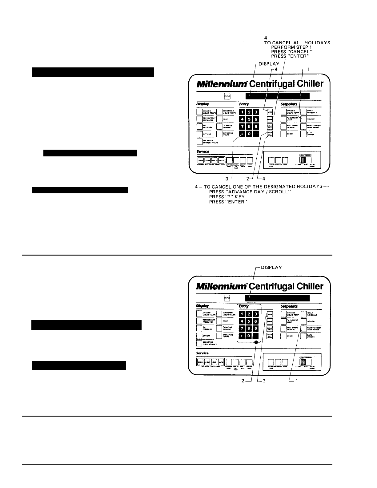
To Enter HOLIDAY Setpoint: (Refer to Fig. 11.)
1. Press and release HOLIDAY setpoint key. The fol-
lowing program prompt message is display ed:
S_ M_ T_ W_ T_ F_ S_ HOLIDAY NOTED BY
r
2. Press and release ADV ANCE DAY/SCR OLL k ey to
move cursor to the day that y ou wish to designate as
a holiday .
3. Press and release r entry key. An r will appear
next to the selected day.
4. After you have placed an r n ext to each of the da ys
that you wish to designate a holiday, press ENTER
key
PROGRAM MODE, SELECT SETPOINT
message is displayed.
T o cancel all of the designated holidays: perform Step
1, press CANCEL key, and then press ENTER key.
PROGRAM MODE, SELECT SETPOINT
message is displayed.
To cancel one of the designated holidays: perform
Step 1, press ADVANCE DAY / SCROLL key until
the cursor appears to the right of the desired day,
press the r key, then press the ENTER key.
LD00961
FIG. 11 – KEYPAD – PROGRAMMING “HOLIDAY”
SETPOINT
To Enter REMOTE/ RESET TEMP RANGE Setpoint:
(Refer to Fig. 12.)
1. Press and release REMOTE/RESET TEMP RANGE
setpoint key . The following program prompt message
is displayed:
REMOTE TEMP SETPOINT RANGE = XX °F
2. Use Entry keys desired value (10 or 20).
3. Press and release ENTER key.
PROGRAM MODE, SELECT SETPOINT
message is displayed.
To Enter DA TA LOGGER Setpoint:
Refer to F orm 160.49-N7 for operation of this k e y.
LD00962
FIG. 12 – KEYPAD – PROGRAMMING “REMO T E
RESET” TEMP RANGE
18 YORK INTERNA TIONAL
Loading…