
Руководства пользователя
Версия T4204
1.97 MB
2009/03/27
Motherboard Installation Guide (Traditional Chinese)
Версия C4204
1.83 MB
2009/03/27
Motherboard Installation Guide (Simplified Chinese)
Версия QJ4204
1.68 MB
2008/10/21
Motherboard Installation Guide (Japanese)
Версия QG4204
1.6 MB
2008/10/21
Motherboard Installation Guide (German)
Версия QF4204
1.59 MB
2008/10/21
Motherboard Installation Guide (French)
Версия Q4204
43.39 MB
2008/10/21
Motherboard Installation Guide (Multiple Languages)
Версия J3279b
2.1 MB
2008/03/06
P5K-VM user’s manual(Japanese)
Версия C3172
1.87 MB
2007/09/02
P5K-VM user’s manual(Simplified Chinese)
Версия T3172
2 MB
2007/09/02
P5K-VM user’s manual(Traditional Chinese)
Версия C3172
1.95 MB
2007/07/11
P5K-VM user’s manual(Simplified Chinese)
Версия T3172
2.08 MB
2007/07/10
P5K-VM user’s manual(Traditional Chinese)
Версия J3279
2.1 MB
2007/07/09
P5K-VM user’s manual(Japanese)
Версия C3172
2.05 MB
2007/06/25
C3172
P5K-VM Simplified Chinese Manual
Версия T3172
2.18 MB
2007/06/25
T3172
P5K-VM Traditional Chinese Manual
Версия E3279
1.82 MB
2007/06/14
P5K-VM user’s manual(English)
Версия e3172
1.8 MB
2007/06/07
P5K-VM User’s Manual for English Edition (e3172)
Версия T2437
2.57 MB
2006/05/17
Motherboard DIY Troubleshooting Guide (Traditional Chinese version)

P5K-VM
Motherboard

E3279
Second Edition V2
June 2007
Copyright © 2007 ASUSTeK COMPUTER INC. All Rights Reserved.
No part of this manual, including the products and software described in it, may be reproduced,
transmitted, transcribed, stored in a retrieval system, or translated into any language in any form or by any
means, except documentation kept by the purchaser for backup purposes, without the express written
permission of ASUSTeK COMPUTER INC. (“ASUS”).
Product warranty or service will not be extended if: (1) the product is repaired, modied or altered, unless
such repair, modication of alteration is authorized in writing by ASUS; or (2) the serial number of the
product is defaced or missing.
ASUS PROVIDES THIS MANUAL “AS IS” WITHOUT WARRANTY OF ANY KIND, EITHER EXPRESS
OR IMPLIED, INCLUDING BUT NOT LIMITED TO THE IMPLIED WARRANTIES OR CONDITIONS OF
MERCHANTABILITY OR FITNESS FOR A PARTICULAR PURPOSE. IN NO EVENT SHALL ASUS, ITS
DIRECTORS, OFFICERS, EMPLOYEES OR AGENTS BE LIABLE FOR ANY INDIRECT, SPECIAL,
INCIDENTAL, OR CONSEQUENTIAL DAMAGES (INCLUDING DAMAGES FOR LOSS OF PROFITS,
LOSS OF BUSINESS, LOSS OF USE OR DATA, INTERRUPTION OF BUSINESS AND THE LIKE),
EVEN IF ASUS HAS BEEN ADVISED OF THE POSSIBILITY OF SUCH DAMAGES ARISING FROM ANY
DEFECT OR ERROR IN THIS MANUAL OR PRODUCT.
SPECIFICATIONS AND INFORMATION CONTAINED IN THIS MANUAL ARE FURNISHED FOR
INFORMATIONAL USE ONLY, AND ARE SUBJECT TO CHANGE AT ANY TIME WITHOUT NOTICE,
AND SHOULD NOT BE CONSTRUED AS A COMMITMENT BY ASUS. ASUS ASSUMES NO
RESPONSIBILITY OR LIABILITY FOR ANY ERRORS OR INACCURACIES THAT MAY APPEAR IN THIS
MANUAL, INCLUDING THE PRODUCTS AND SOFTWARE DESCRIBED IN IT.
Products and corporate names appearing in this manual may or may not be registered trademarks or
copyrights of their respective companies, and are used only for identication or explanation and to the
owners’ benet, without intent to infringe.
ii

Contents
Notices …………………………………………………………………………………………… vi
Safety information …………………………………………………………………………. vii
P5K-VM specications summary ……………………………………………………… x
Chapter 1: Product introduction
1.1 Welcome! ………………………………………………………………………….. 1-2
1.2 Package contents ……………………………………………………………….
1.3 Special features ………………………………………………………………….
1.3.1 Product highlights …………………………………………………..
1.3.2 ASUS AI Lifestyle features ……………………………………….
1.3.3 ASUS Stylish features ……………………………………………..
1.3.4 ASUS Intelligent Overclocking features ……………………..
1.4 Before you proceed ……………………………………………………………
1.5 Motherboard overview ………………………………………………………..
1.5.1 Placement direction ………………………………………………..
1.5.2 Screw holes …………………………………………………………..
1.5.3 Motherboard layout …………………………………………………
1.6 Central Processing Unit (CPU) ………………………………………….
1.6.1 Installing the CPU ………………………………………………….
1.6.2 Installing the CPU heatsink and fan …………………………
1.6.3 Uninstalling the CPU heatsink and fan …………………….
1.7 System memory ……………………………………………………………….
1.7.1 Overview ……………………………………………………………..
1.7.2 Memory congurations …………………………………………..
1.7.3 Installing a DIMM ………………………………………………….
1.7.4 Removing a DIMM ………………………………………………..
1.8 Expansion slots ………………………………………………………………..
1.8.1 Installing an expansion card …………………………………..
1.8.2 Conguring an expansion card ……………………………….
1.8.3 Interrupt assignments ……………………………………………
1.8.4 PCI slots ………………………………………………………………
1.8.5 PCI Express x4 slot ……………………………………………….
1.8.6 PCI Express x16 slot ……………………………………………..
1.9 Jumper …………………………………………………………………………….
1.10 Connectors ………………………………………………………………………
1.10.1 Rear panel connectors …………………………………………..
1-2
1-3
1-3
1-5
1-6
1-6
1-7
1-8
1-8
1-8
1-9
1-10
1-11
1-13
1-15
1-17
1-17
1-18
1-22
1-22
1-23
1-23
1-23
1-24
1-25
1-25
1-25
1-26
1-28
1-28
iii

Contents
1.10.2 Internal connectors ………………………………………………. 1-30
Chapter 2: BIOS setup
2.1 Managing and updating your BIOS …………………………………….. 2-2
2.1.1 ASUS Update utility ………………………………………………..
2.1.2 Creating a bootable oppy disk …………………………………
2.1.3 ASUS EZ Flash 2 utility ……………………………………………
2.1.4 AFUDOS utility ……………………………………………………….
2.1.5 ASUS CrashFree BIOS 3 utility ………………………………..
2.2 BIOS setup program …………………………………………………………
2.2.1 BIOS menu screen …………………………………………………
2.2.2 Menu bar ………………………………………………………………
2.2.3 Navigation keys ……………………………………………………..
2.2.4 Menu items ………………………………………………………….
2.2.5 Sub-menu items ……………………………………………………
2.2.6 Conguration elds ……………………………………………….
2.2.7 Pop-up window …………………………………………………….
2.2.8 Scroll bar ……………………………………………………………..
2.2.9 General help ………………………………………………………..
2.3 Main menu ……………………………………………………………………….
2.3.1 System Time ………………………………………………………..
2.3.2 System Date ………………………………………………………..
2.3.3 Legacy Diskette A …………………………………………………
2.3.4
2.3.5 IDE Conguration ………………………………………………….
2.3.6 System Information ……………………………………………….
2.4 Advanced menu ……………………………………………………………….
2.4.1 Jumperfree Conguration ………………………………………
2.4.2 USB Conguration ………………………………………………..
2.4.3 CPU Conguration ………………………………………………..
2.4.4 Chipset ………………………………………………………………..
2.4.5 OnBoard Devices Conguration ……………………………..
2.4.6 PCIPnP ……………………………………………………………….
2.5 Power menu ……………………………………………………………………..
2.5.1 Suspend Mode [Auto] ……………………………………………
2.5.2 Repost Video on S3 Resume [Disabled] …………………..
SATA 1~4; PATA Primary Master/Slave …………………………………2-14
2-2
2-5
2-6
2-7
2-9
2-10
2-11
2-11
2-11
2-12
2-12
2-12
2-12
2-12
2-12
2-13
2-13
2-13
2-13
2-15
2-16
2-17
2-17
2-20
2-22
2-23
2-25
2-26
2-27
2-27
2-27
iv

Contents
2.5.3 ACPI Version [Disabled] ………………………………………… 2-27
2.5.4 ACPI APIC Support [Enabled] …………………………………
2.5.5 APM Conguration ………………………………………………..
2.5.6 Hardware Monitor …………………………………………………
2.6 Boot menu ……………………………………………………………………….
2.6.1 Boot Device Priority ………………………………………………
2.6.2 Boot Settings Conguration ……………………………………
2.6.3 Security ……………………………………………………………….
2.7 Tools menu ………………………………………………………………………
2.7.1 ASUS EZ Flash 2 ………………………………………………….
2.7.2 AI Net 2 ……………………………………………………………….
2.8 Exit menu …………………………………………………………………………
Chapter 3: Software support
3.1 Installing an operating system …………………………………………… 3-2
3.2 Support CD information …………………………………………………….. 3-2
3.2.1 Running the support CD …………………………………………. 3-2
3.2.2 Drivers menu …………………………………………………………. 3-3
3.2.3 Utilities menu ………………………………………………………… 3-4
3.2.4 Manual menu ………………………………………………………… 3-6
3.2.5 ASUS Contact information ………………………………………. 3-6
3.2.6 Other information …………………………………………………… 3-7
2-27
2-28
2-29
2-31
2-31
2-32
2-33
2-35
2-35
2-36
2-37
v

Notices
Federal Communications Commission Statement
This device complies with Part 15 of the FCC Rules. Operation is subject to the
following two conditions:
•
This device may not cause harmful interference, and
•
This device must accept any interference received including interference that
may cause undesired operation.
This equipment has been tested and found to comply with the limits for a
Class B digital device, pursuant to Part 15 of the FCC Rules. These limits are
designed to provide reasonable protection against harmful interference in a
residential installation. This equipment generates, uses and can radiate radio
frequency energy and, if not installed and used in accordance with manufacturer’s
instructions, may cause harmful interference to radio communications. However,
there is no guarantee that interference will not occur in a particular installation. If
this equipment does cause harmful interference to radio or television reception,
which can be determined by turning the equipment off and on, the user is
encouraged to try to correct the interference by one or more of the following
measures:
•
Reorient or relocate the receiving antenna.
•
Increase the separation between the equipment and receiver.
•
Connect the equipment to an outlet on a circuit different from that to which the
receiver is connected.
•
Consult the dealer or an experienced radio/TV technician for help.
The use of shielded cables for connection of the monitor to the graphics card is
required to assure compliance with FCC regulations. Changes or modications
to this unit not expressly approved by the party responsible for compliance
could void the user’s authority to operate this equipment.
Canadian Department of Communications Statement
This digital apparatus does not exceed the Class B limits for radio noise emissions
from digital apparatus set out in the Radio Interference Regulations of the
Canadian Department of Communications.
This class B digital apparatus complies with Canadian ICES-003.
vi

Safety information
Electrical safety
•
To prevent electrical shock hazard, disconnect the power cable from the
electrical outlet before relocating the system.
•
When adding or removing devices to or from the system, ensure that the
power cables for the devices are unplugged before the signal cables are
connected. If possible, disconnect all power cables from the existing system
before you add a device.
•
Before connecting or removing signal cables from the motherboard, ensure
that all power cables are unplugged.
•
Seek professional assistance before using an adpater or extension cord.
These devices could interrupt the grounding circuit.
•
Make sure that your power supply is set to the correct voltage in your area.
If you are not sure about the voltage of the electrical outlet you are using,
contact your local power company.
•
If the power supply is broken, do not try to x it by yourself. Contact a
qualied service technician or your retailer.
Operation safety
•
Before installing the motherboard and adding devices on it, carefully read all
the manuals that came with the package.
•
Before using the product, make sure all cables are correctly connected and the
power cables are not damaged. If you detect any damage, contact your dealer
immediately.
•
To avoid short circuits, keep paper clips, screws, and staples away from
connectors, slots, sockets and circuitry.
•
Avoid dust, humidity, and temperature extremes. Do not place the product in
any area where it may become wet.
•
Place the product on a stable surface.
•
If you encounter technical problems with the product, contact a qualied
service technician or your retailer.
This symbol of the crossed out wheeled bin indicates that the product (electrical
and electronic equipment) should not be placed in municipal waste. Check local
regulations for disposal of electronic products.
vii

About this guide
This user guide contains the information you need when installing and conguring
the motherboard.
How this guide is organized
This guide contains the following parts:
• Chapter 1: Product introduction
This chapter describes the features of the motherboard and the new
technology it supports. It also lists the hardware setup procedures that you
have to perform when installing system components. It includes description of
the jumpers and connectors on the motherboard.
• Chapter 2: BIOS setup
This chapter tells how to change system settings through the BIOS Setup
menus. Detailed descriptions of the BIOS parameters are also provided.
• Chapter 3: Software support
This chapter describes the contents of the support CD that comes with the
motherboard package.
Where to nd more information
Refer to the following sources for additional information and for product and
software updates.
1. ASUS websites
The ASUS website provides updated information on ASUS hardware and
software products. Refer to the ASUS contact information.
2. Optional documentation
Your product package may include optional documentation, such as warranty
yers, that may have been added by your dealer. These documents are not
part of the standard package.
viii
Conventions used in this guide
To make sure that you perform certain tasks properly, take note of the following
symbols used throughout this manual.
DANGER/WARNING: Information to prevent injury to yourself
when trying to complete a task.
CAUTION: Information to prevent damage to the components
when trying to complete a task.
IMPORTANT: Instructions that you MUST follow to complete a
task.
NOTE: Tips and additional information to help you complete a
task.
Typography
Bold text Indicates a menu or an item to select.
Italics
Used to emphasize a word or a phrase.
<Key> Keys enclosed in the less-than and greater-than sign
means that you must press the enclosed key.
Example: <Enter> means that you must press the
Enter or Return key.
<Key1>+<Key2>+<Key3> If you must press two or more keys simultaneously, the
key names are connected with a plus sign (+).
Example: <Ctrl>+<Alt>+<D>
Command Means that you must type the command exactly as
shown.
Example: At the DOS prompt, type the command line:
afudos /iP5K-VM.ROM
ix

P5K-VM specications summary
CPU LGA775 socket for Intel® Core™2 Quad / Core™2
Chipset Intel® G33 / ICH9 with Intel® Fast Memory Access
System bus 1333/1066/800 MHz
Memory Dual-channel memory architecture
VGA Intel® Graphics Media Accelerator 3100 integrated
Expansion slots 1 x PCI Express™ x16 slot
Storage Southbridge
LAN Marvell88E8056® PCI-E Gigabit LAN controller
Audio Realtek® ALC883 8-channel High-Denition Audio CODEC
IEEE 1394 VIA controller supports 2 x IEEE 1394a ports
USB 12 x USB 2.0 ports (6 at mid-board, 6 at back panel)
Extreme / Core™2 Duo / Pentium® Extreme / Pentium®
D / Pentium® 4 processors
Compatible with Intel® 05B/05A/06 processors
Supports Intel® next-generation 45nm multi-core CPUs
Technology
— 4 x 240-pin DIMM sockets support unbuffered
non-ECC DDR2 1066*/800/667MHz memory
modules
— Supports up to 8 GB system memory
* The chipset ofcially supports the memory frequency up
to DDR2 800MHz. Tuned by the ASUS Super Memspeed
Technology, this motherboard natively supports up to
DDR2 1066MHz.
Refer to www.asus.com or this user manual for the
Memory QVL (Qualied Vendors Lists).
High-denition video processing with a maximum
resolution of 2084 x 1536 bpp @ 75 Hz
Maximum shared memory of 256 MB
Supports Microsoft® DirectX®9, OpenGL®1.5,
Pixel Shader 2.0
1 x PCI Express™ x4 slot
2 x PCI slots
— 4 x Serial ATA 3.0 Gb/s ports
JMicron® JMB368 PATA and SATA controller supports:
— 1 x UltraDMA 133/100/66 for up to 2 PATA devices
PCIe Gb LAN controller featuring AI NET2
— Supports Jack-Sensing, Enumeration,
Multi-Streaming
— Coaxial S/PDIF out port at back I/O
— ASUS Noise Filter
(one at midboard; one at back panel)
(continued on the next page)
x

P5K-VM specications summary
AI Lifestyle Unique
features
Other features ASUS MyLogo2
ASUS Exclusive
Overclocking features
Rear panel connectors 1 x PS/2 keyboard port
Internal connectors 3 x USB connectors support 6 additional USB ports
ASUS AI Lifestyle features:
— ASUS AI Gear2
— ASUS AI Nap
— ASUS Q-Fan
ASUS Crystal Sound:
— ASUS Noise Filter
ASUS EZ DIY:
— ASUS Q-Connector
— ASUS CrashFree BIOS 3
— ASUS EZ Flash 2
ASUS Super Memspeed Technology
vCore: Adjustable CPU voltage at 0.0125V increment
SFS (Stepless Frequency Selection:
— FSB tuning from 200MHz to 800 MHz at 1MHz
increment
— Memory tuning from 667MHz to 1333MHz for DDR2
— PCI-E frequency tuning from 100MHz to 150MHz at
1 MHz increment
Overclocking protection:
— ASUS C.P.R. (CPU Parameter Recall)
1 x Parallel port
1 x Coaxial S/PDIF Out port
1 x IEEE1394a
1 x LAN (RJ-45) port
6 x USB 2.0/1.1 ports
8-channel audio ports
1 x Floppy disk drive connector
1 x IDE connector
4 x Serial ATA connectors
1 x CPU / 1 x Chassis / 1 x Power fan connectors
1 x IEEE1394a connector
1 x COM connector
1 x S/PDIF Out header
Chassis intrusion connector
Front panel audio connector
CD audio in connector
24-pin ATX power connector
4-pin ATX 12 V power connector
System panel connector (Q-Connector)
(continued on the next page)
xi

P5K-VM specications summary
BIOS features 8 Mb Flash ROM, AMI BIOS, PnP, DMI2.0, WfM2.0,
Manageability WfM 2.0, DMI 2.0, WOL by PME, WOR by PME, PXE
Support CD contents Drivers
Form factor uATX form factor: 9.6 in x 9.6 in (24.4 cm x 24.4 cm)
*Specications are subject to change without notice.
SM BIOS 2.3, ACPI 2.0a, ASUS CrashFree BIOS 3,
ASUS EZ Flash 2
ASUS PC Probe II
ASUS Update
ASUS AI Suite
Anti-virus software (OEM version)
xii

This chapter describes the motherboard
features and the new technologies
it supports.
Product
1
introduction
1.1 Welcome!
Thank you for buying an ASUS® P5K-VM motherboard!
The motherboard delivers a host of new features and latest technologies, making it
another standout in the long line of ASUS quality motherboards!
Before you start installing the motherboard, and hardware devices on it, check the
items in your package with the list below.
1.2 Package contents
Check your motherboard package for the following items.
Motherboard ASUS P5K-VM
Cables Serial ATA signal cable for 2 devices
Serial ATA power cable for 2 devices
1 x Ultra DMA 133/100/66 cable
1 x Floppy disk drive cable
Accessories I/O shield
1 x ASUS Q-Connector Kit (USB, 1394, system
panel; Retail version only)
Application CD ASUS motherboard support CD
ASUS Superb Software Library CD
Documentation User guide
If any of the above items is damaged or missing, contact your retailer.
1-2 Chapter 1: Product Introduction
1.3 Special features
1.3.1 Product highlights
Green ASUS
This motherboard and its packaging comply with the European Union’s Restriction
on the use of Hazardous Substances (RoHS). This is in line with the ASUS vision
of creating environment-friendly and recyclable products/packaging to safeguard
consumers’ health while minimizing the impact on the environment.
Intel® Quad-core Processor Ready
This motherboard supports the latest Intel® Quad-core processors in the LGA775
package and Intel’s next-generation 45nm multi-core processors. It is excellent for
multi-tasking, multi-media and enthusiastic gamers with 1333/1066/800 MHz FSB.
Intel® Quad-core processor is one of the most powerful CPU in the world. See
page 1-10 for details.
Intel® Core™2 Duo/ Intel® Core™2 Extreme CPU support
This motherboard supports the latest Intel® Core™2 processor in the LGA775
package and Intel’s next-generation 45nm multi-core processors. With the new
Intel® Core™ microarchitecture technology and 1333/1066/800 MHz FSB, the
Intel® Core™2 is one of the most powerful and energy efcient CPUs in the world.
See page 1-10 for details.
Intel G33 Chipset
The Intel® G33 Express Chipset boosts your gaming and multimedia experience
with the integrated graphics engine Intel® Graphics Media Accelerator 3100. It
supports 1333 FSB (Front Side Bus), and delivers breakthrough advances in 3D
and 2D graphics as well as video capabilities. This integrated chipset is able to
meet the changing display requirements of visually rich applications. It features
the Intel® Clear Video Technology, which supports crisp imaging, accurate color
control, and High-Denition video processing with a maximum resolution of
2084 x 1536 bpp @ 75 Hz and a maximum shared memory of 256 MB.
DDR2 memory support
The motherboard supports DDR2 memory that features data transfer rates of
800/667 MHz to meet the higher bandwidth requirements of the latest 3D graphics,
multimedia, and Internet applications. The dual-channel DDR2 architecture
doubles the bandwidth of your system memory to boost system performance,
eliminating bottlenecks with peak bandwidths of up to 12.8 GB/s. Furthermore, this
motherboard does not restrict the memory size across two channels. Users may
install different memory size DIMMs into the two channels and enjoy dual-channel
and single-channel functions at the same time. This new feature optimizes the use
of available memory size. See page 1-17 for details.
ASUS P5K-VM 1-3
Native DDR2 1066 memory support
To attain top performance, ASUS engineers have successfully unleashed the
true potential of DDR2 memory. While in DDR2 1066 mode, ASUS’s exclusive
technology offers a choice of FSB 1333, providing great performance for 3D
graphics and other memory demanding applications. See page 1-17 for details.
ASUS Super Memspeed Technology
To attain top performance, ASUS has managed to break through current FSB
and DRAM ratio proportions by utilizing Super Memspeed Technology–the latest
technology that provides even more precise overclocking options to unleash the
true potential of DDR2 memory. The DDR2 Mode maximizes system performance
by eliminating the bottleneck when overclocking both the CPU and memory–
providing great performance for 3D graphics and other memory demanding
applications. See page 1-17 for details.
Serial ATA 3.0 Gb/s technology
This motherboard supports the next-generation hard drives based on the Serial
ATA (SATA) 3Gb/s storage specication, delivering enhanced scalability and
doubling the bus bandwidth for high-speed data retrieval and saves. See page
1-32 for details.
IEEE 1394a support
The IEEE 1394a interface provides high speed digital interface for audio/video
appliances such as digital television, digital video camcorders, storage peripherals
& other PC portable devices. See page1-28 and 1-34 for details.
S/PDIF digital sound ready
This motherboard provides convenient connectivity to external home theater audio
systems via coaxial and optical S/PDIF-out (SONY-PHILIPS Digital Interface)
jacks.It allows to transfer digital audio without converting to analog format and
keeps the best signal quality. See pages 1-29 for details.
High Denition Audio
Enjoy high-end sound quality on your PC! The onboard 8-channel High Denition
Audio CODEC enables high-quality 192KHz/24-bit audio output, jack-sensing
feature, and multi-streaming technology that simultaneously sends different
audio streams to different destinations. You can now talk to your partners on the
headphone while playing multi-channel network games. See page 1-28 and 1-29
for details.
1-4 Chapter 1: Product Introduction
1.3.2 ASUS AI Lifestyle features
ASUS Quiet Thermal Solution
ASUS Quiet Thermal solution makes system more stable and enhances the
overclocking capability.
AI Gear 2
AI Gear 2 allows you to choose proles to adjust the CPU frequency and
Vcore voltage to minimize system noise and power consumption. You can
change the mode in real-time in the operating system to max power saving
mode and save up to 50% power when using word processing applications.
AI Nap
With AI Nap, the system can continue running at minimum power and noise
when you are temporarily away. To wake the system and return to the OS
environment, simply click the mouse or press a key.
Q-Fan
ASUS Q-Fan technology intelligently adjusts both CPU fan and chassis fan
speeds according to system loading to ensure quiet, cool and efcient operation.
ASUS Crystal Sound
This feature can enhance speech-centric applications like Skype, online game,
video conference and recording.
Noise Filter
This feature detects repetitive and stationary noises (non-voice signals) like
computer fans, air conditioners, and other background noises then eliminates
it in the incoming audio stream while recording.
ASUS EZ DIY
ASUS EZ DIY feature collection provides you easy ways to install computer
components, update the BIOS or back up your favorite settings.
ASUS Q-Connector
ASUS Q-Connector allows you to easily connect or disconnect the chassis
front panel cables to the motherboard. This unique module eliminates the
trouble of connecting the system panel cables one at a time and avoiding
wrong cable connections. See page 1-33, 1-34, and 1-39 for details.
ASUS P5K-VM 1-5
ASUS CrashFree BIOS 3
The ASUS CrashFree BIOS 3 allows users to restore corrupted BIOS data
from a USB ash disk containing the BIOS le. See page 2-9 for details.
ASUS EZ Flash 2
EZ Flash 2 is a user-friendly BIOS update utility. Simply press the predened
hotkey to launch the utility and update the BIOS without entering the OS.
Update your BIOS easily without preparing a bootable diskette or using an
OS-based ash utility. See page 2-6 for details.
1.3.3 ASUS Stylish features
ASUS MyLogo2™
This feature allows you to convert your favorite photo into a 256-color boot logo for
a more colorful and vivid image on your screen. See page 2-32 for details.
AI NET 2
AI NET 2 is a BIOS-based diagnostic tool that detects and reports Ethernet cable
faults and shorts. With this utility, you can easily monitor the condition of the
Ethernet cable(s) connected to the Marvell® LAN (RJ-45) port. During the bootup
process, AI NET 2 immediately diagnoses the LAN cable and reports shorts and
faults up to 100 meters at 1 meter accuracy. See page 2-36 for details.
Smart Support CD
It provides a checklist to allow the user to see which drivers are already installed,
as well as those that aren’t. When using ASUS PC Probe II, you can easily see the
critical parts of the computer.
1.3.4 ASUS Intelligent Overclocking features
C.P.R. (CPU Parameter Recall)
The C.P.R. feature of the motherboard BIOS allows automatic re-setting to the
BIOS default settings in case the system hangs due to overclocking. When the
system hangs due to overclocking, C.P.R. eliminates the need to open the system
chassis and clear the RTC data. Simply shut down and reboot the system, and the
BIOS automatically restores the CPU default setting for each parameter. See page
1-26 for details.
1-6 Chapter 1: Product Introduction
1.4 Before you proceed
P5K-VM
®
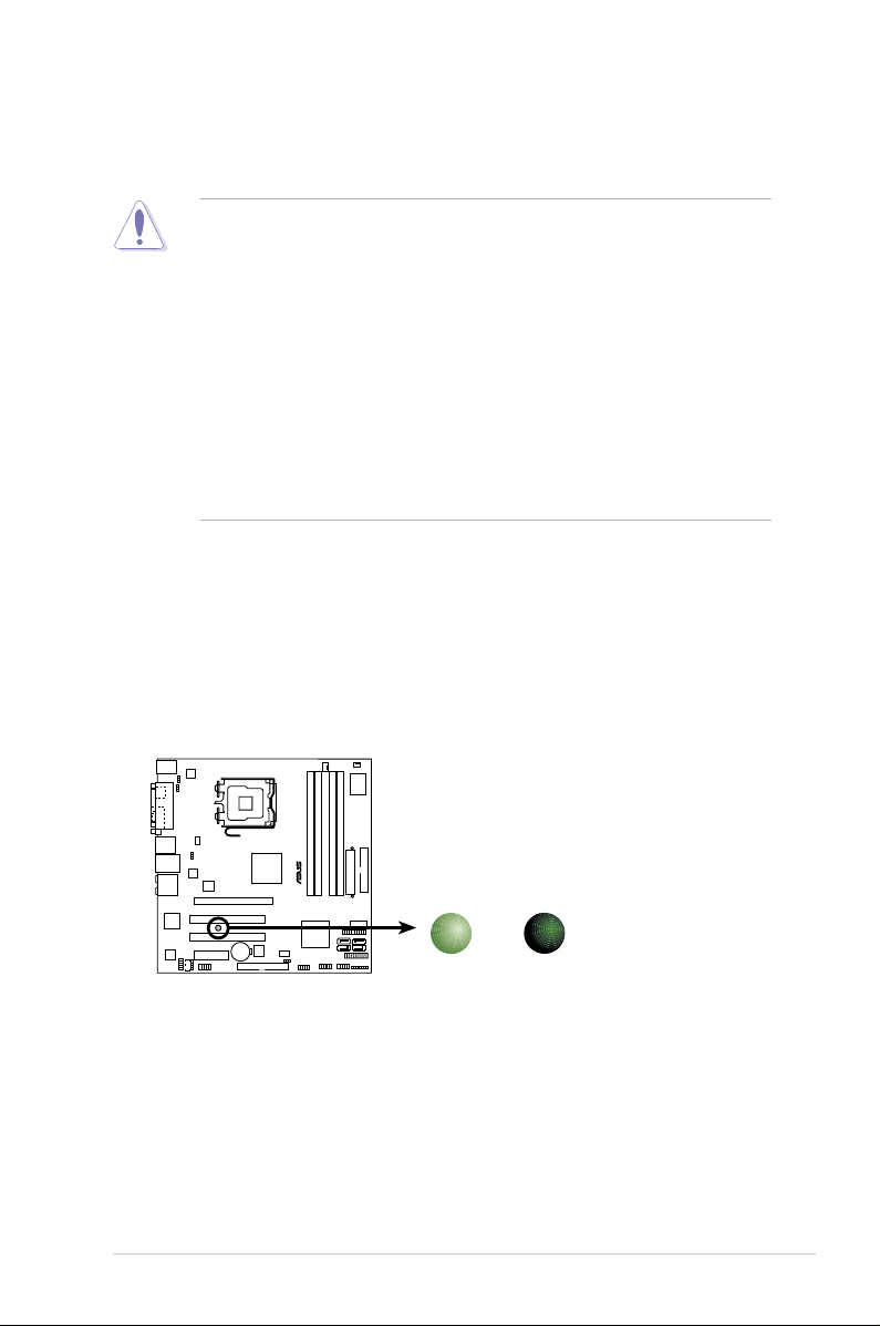
P5K-VM Onboard LED
SB_PWR
ON
Standby
Power
OFF
Powered
Off
Take note of the following precautions before you install motherboard components
or change any motherboard settings.
• Unplug the power cord from the wall socket before touching any
component.
• Use a grounded wrist strap or touch a safely grounded object or a metal
object, such as the power supply case, before handling components to
avoid damaging them due to static electricity.
• Hold components by the edges to avoid touching the ICs on them.
• Whenever you uninstall any component, place it on a grounded antistatic
pad or in the bag that came with the component.
• Before you install or remove any component, ensure that the ATX power
supply is switched off or the power cord is detached from the power
supply. Failure to do so may cause severe damage to the motherboard,
peripherals, and/or components.
Onboard LED
The motherboard comes with a standby power LED that lights up to indicate that
the system is ON, in sleep mode, or in soft-off mode. This is a reminder that you
should shut down the system and unplug the power cable before removing or
plugging in any motherboard component. The illustration below shows the location
of the onboard LED.
ASUS P5K-VM 1-7
1.5 Motherboard overview
Before you install the motherboard, study the conguration of your chassis to
ensure that the motherboard ts into it.
Make sure to unplug the power cord before installing or removing the
motherboard. Failure to do so can cause you physical injury and damage
motherboard components.
1.5.1 Placement direction
When installing the motherboard, make sure that you place it into the chassis in
the correct orientation. The edge with external ports goes to the rear part of the
chassis as indicated in the image below.
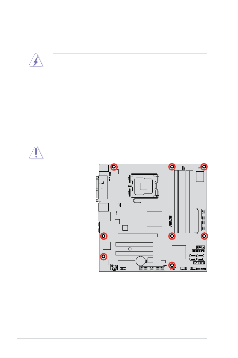
1.5.2 Screw holes
Place eight (8) screws into the holes indicated by circles to secure the motherboard
to the chassis.
Do not overtighten the screws! Doing so can damage the motherboard.
Place this side towards
the rear of the chassis
1-8 Chapter 1: Product introduction
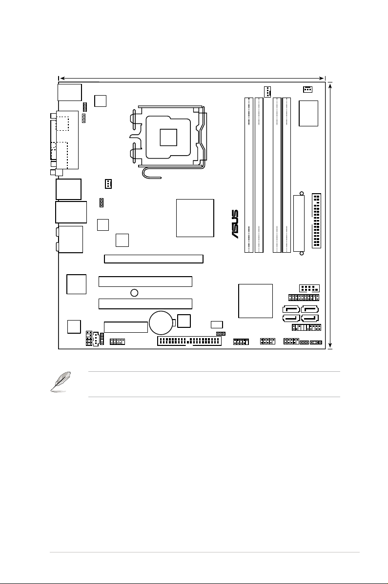
VGA
PANEL
P5K-VM
®
AAFP
CHASSIS
24.4cm (9.6in)
24.4cm (9.6in)
CPU_FAN
DDR2 DIMM_B1 (64 bit,240-pin module)
DDR2 DIMM_A1 (64 bit,240-pin module)
DDR2 DIMM_A2 (64 bit,240-pin module)
DDR2 DIMM_B2 (64 bit,240-pin module)
Super
I/O
CD
PCIEX4_1
CLRTC
Intel
®
ICH9
EATXPWR
CR2032 3V
Lithium Cell
CMOS Power
Intel
®
MCH
G33
PCI1
PCIEX16_1
CHA_FAN1
SPDIF_OUT
LGA775
IE1394_2
BIOS
SATA1
ATX12V
ALC883
PWR_FAN
PCI2
F_USB34
KB_USB56
LAN1_USB12
VIA
VT6308S
PRI_EIDE
KBPWR
USB78
SB_PWR
COM1
USBPW1-4
USBPW9-12
AUDIO
USB910USB1112
ASM4131
88E8056
USBPW5-8
SATA2
SATA4
SATA3
FLOPPY
PARALLEL PORT
SPDIF
JMicron
JMB368
1.5.3 Motherboard layout
and internal connectors.
Refer to 1.10 Connectors for more information about rear panel connectors
ASUS P5K-VM 1-9

1.6 Central Processing Unit (CPU)
The motherboard comes with a surface mount LGA775 socket designed for
the Intel® Core™2 Quad / Core™2 Extreme / Core™2 Duo / Pentium® Extreme /
Pentium® D/ Pentium® 4 processors.
• Make sure that all power cables are unplugged before installing the CPU.
• Connect the chassis fan cable to the CHA_FAN1 connector to ensure
system stability.
•
Upon purchase of the motherboard, make sure that the PnP cap is on
the socket and the socket contacts are not bent. Contact your retailer
immediately if the PnP cap is missing, or if you see any damage to the PnP
cap/socket contacts/motherboard components. ASUS will shoulder the cost
of repair only if the damage is shipment/transit-related.
•
Keep the cap after installing the motherboard. ASUS will process Return
Merchandise Authorization (RMA) requests only if the motherboard comes
with the cap on the LGA775 socket.
• The product warranty does not cover damage to the socket contacts
resulting from incorrect CPU installation/removal, or misplacement/loss/
incorrect removal of the PnP cap.
1-10 Chapter 1: Product introduction
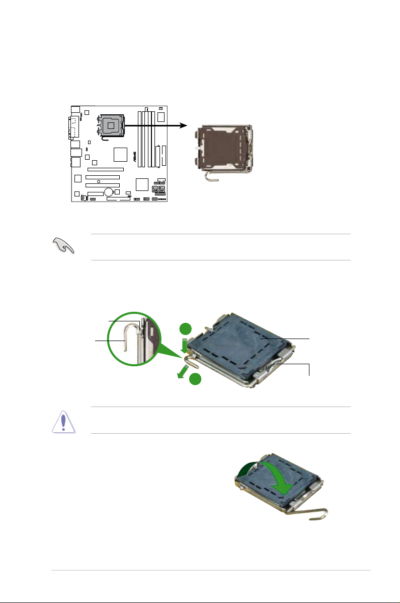
1.6.1 Installing the CPU
P5K-VM
®
P5K-VM CPU Socket 775
To install a CPU:
1. Locate the CPU socket on the motherboard.
Before installing the CPU, make sure that the cam box is facing towards you
and the load lever is on your left.
2. Press the load lever with your thumb (A), then move it to the left (B) until it is
released from the retention tab.
Retention tab
Load lever
3. Lift the load lever in the direction of
the arrow to a 135º angle.
ASUS P5K-VM 1-11
A
PnP cap
B
This side of the socket box
should face you.
To prevent damage to the socket pins, do not remove the PnP cap unless you
are installing a CPU.
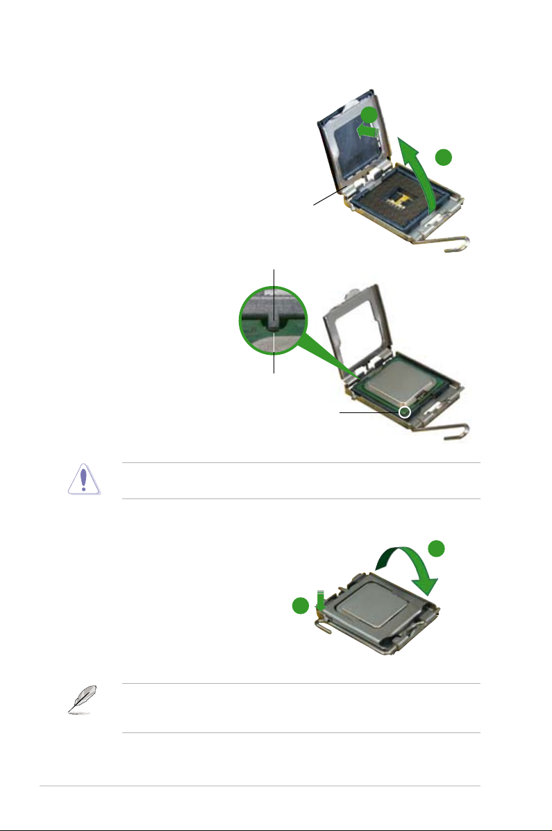
4. Lift the load plate with your thumb
and forenger to a 100º angle (A),
then push the PnP cap from the load
plate window to remove (B).
Alignment key
5. Position the CPU over the
socket, making sure that
the gold triangle is on the
bottom-left corner of the
socket then t the socket
alignment key into the
CPU notch.
The CPU ts in only one correct orientation. DO NOT force the CPU into the
socket to prevent bending the connectors on the socket and damaging the CPU!
CPU notch
Gold triangle mark
B
A
Load plate
6. Close the load plate (A), then
A
push the load lever (B) until it
snaps into the retention tab.
7. If installing a dual-core CPU,
connect the chassis fan cable
B
to the CHA_FAN1 connector to
ensure system stability.
The motherboard supports Intel® LGA775 processors with the Intel® Enhanced
Memory 64 Technology (EM64T), Enhanced Intel SpeedStep® Technology
(EIST), and Hyper-Threading Technology.
1-12 Chapter 1: Product introduction
1.6.2 Installing the CPU heatsink and fan
The Intel® LGA775 processor requires a specially designed heatsink and fan
assembly to ensure optimum thermal condition and performance.
•
When you buy a boxed Intel® processor, the package includes the CPU fan
and heatsink assembly. If you buy a CPU separately, make sure that you use
only Intel®-certied multi-directional heatsink and fan.
•
Your Intel® LGA775 heatsink and fan assembly comes in a push-pin design
and requires no tool to install.
•
If you purchased a separate CPU heatsink and fan assembly, make sure that
you have properly applied Thermal Interface Material to the CPU heatsink or
CPU before you install the heatsink and fan assembly.
Make sure that you have installed the motherboard to the chassis before you
install the CPU fan and heatsink assembly.
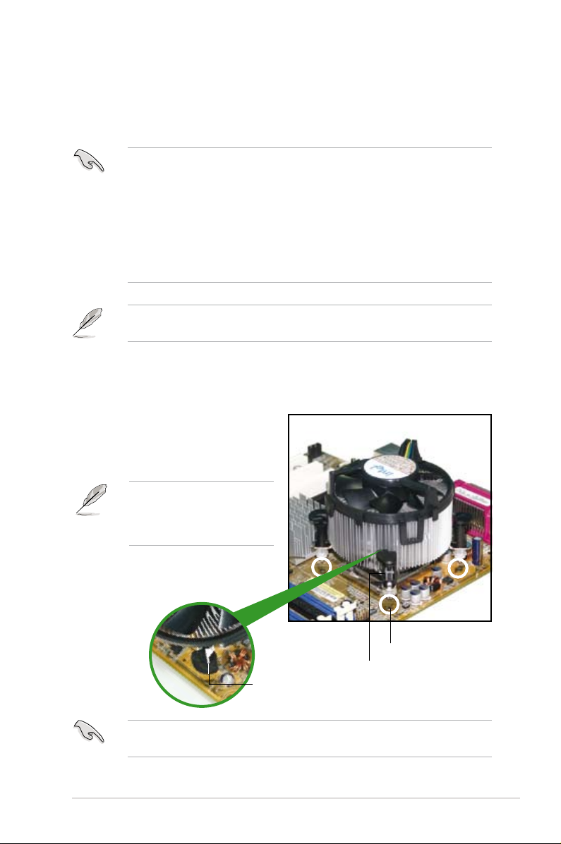
To install the CPU heatsink and fan:
1. Place the heatsink on top of the
installed CPU, making sure that
the four fasteners match the holes
on the motherboard.
Orient the heatsink and fan
assembly such that the CPU
fan cable is closest to the CPU
fan connector.
Motherboard hole
Narrow end
of the groove
Make sure to orient each fastener with the narrow end of the groove pointing
outward. (The photo shows the groove shaded for emphasis.)
ASUS P5K-VM 1-13
Fastener
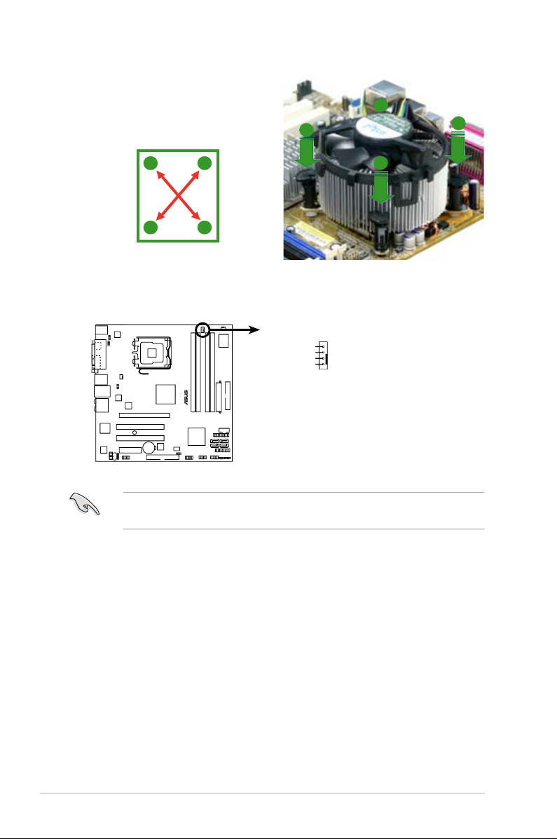
2. Push down two fasteners at a time in
P5K-VM
®
P5K-VM CPU fan connector
CPU_FAN
GND
CPU FAN PWR
CPU FAN IN
CPU FAN PWM
a diagonal sequence to secure the
heatsink and fan assembly in place.
B
A
A
A
B
B
A
B
3. Connect the CPU fan cable to the connector on the motherboard labeled
CPU_FAN.
Do not forget to connect the CPU fan connector! Hardware monitoring errors
can occur if you fail to plug this connector.
1-14 Chapter 1: Product introduction
1.6.3 Uninstalling the CPU heatsink and fan
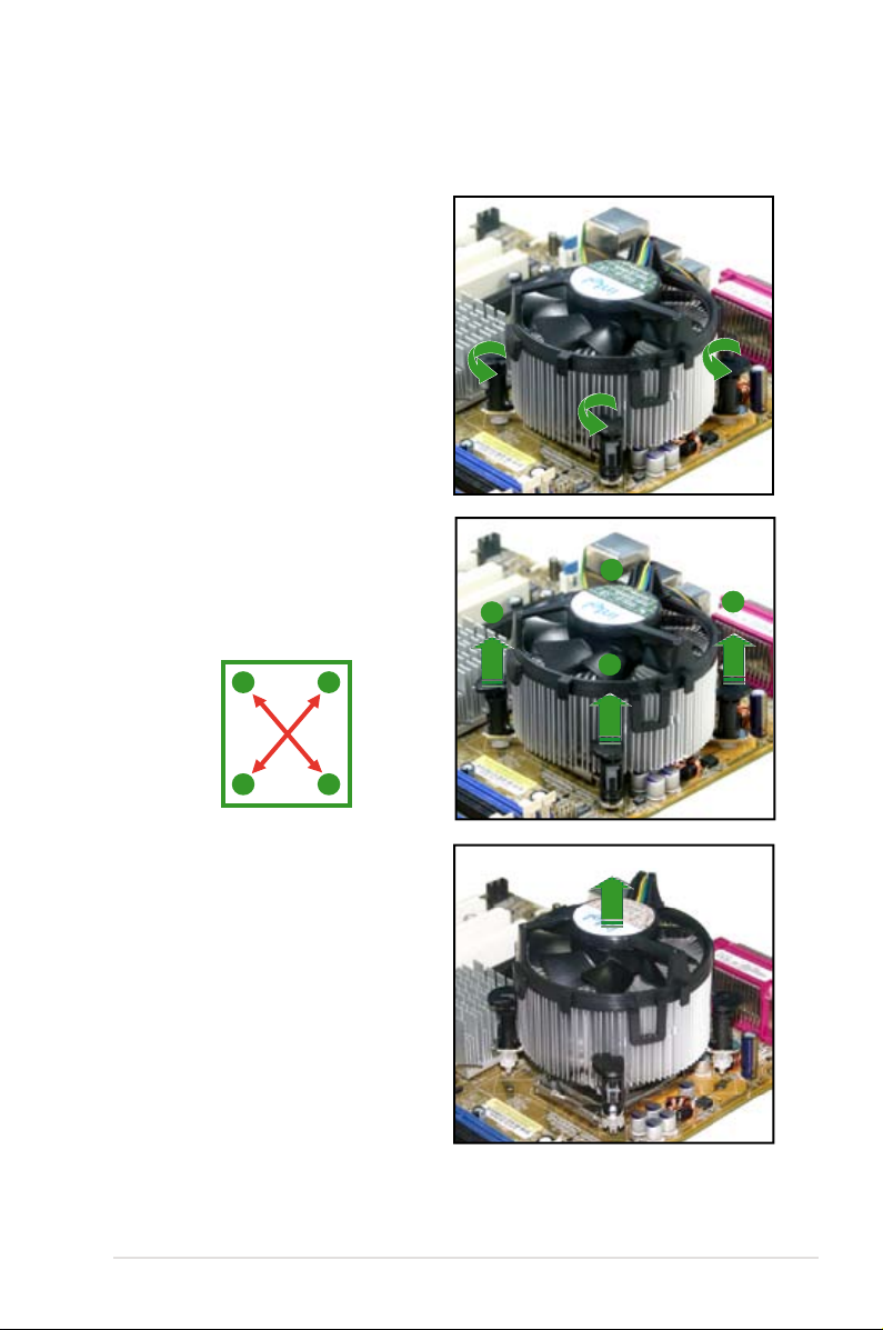
To uninstall the CPU heatsink and fan:
1. Disconnect the CPU fan cable from
the connector on the motherboard.
2. Rotate each fastener
counterclockwise.
3. Pull up two fasteners at a time in
a diagonal sequence to disengage
the heatsink and fan assembly
from the motherboard.
A
B
A
A
B
B
A
B
4. Carefully remove the heatsink
and fan assembly from the
motherboard.
ASUS P5K-VM 1-15
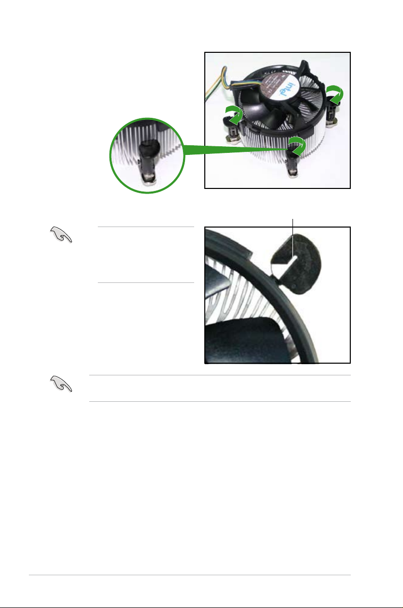
5. Rotate each fastener clockwise to
ensure correct orientation when
reinstalling.
The narrow end of the
groove should point outward
after resetting. (The photo
shows the groove shaded
for emphasis.)
Narrow end of the groove
Refer to the documentation in the boxed or stand-alone CPU fan package for
detailed information on CPU fan installation.
1-16 Chapter 1: Product introduction
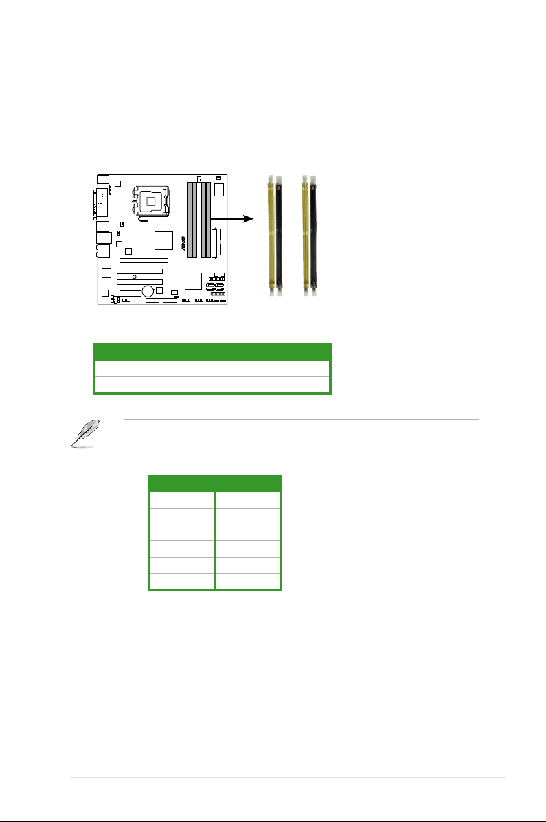
1.7 System memory
P5K-VM
®
P5K-VM 240-pin DDR2 DIMM sockets
DIMM_A2
DIMM_A1
DIMM_B2
DIMM_B1
1.7.1 Overview
The motherboard comes with four Double Data Rate 2 (DDR2) Dual Inline Memory
Modules (DIMM) sockets.
The gure illustrates the location of the DDR2 DIMM sockets:
Channel Sockets
Channel A DIMM_A1 and DIMM_A2
Channel B DIMM_B1 and DIMM_B2
• This chipset ofcially supports DDR2-800 MHz. With the ASUS Super
Memspeed Technology, this motherboard natively supports up to
DDR2-1066 MHz. See the table below.
FSB DDR2
1333 1066*
1333 800
1333 667
1066 1066*
1066 800
1066 667
• *If you install a DDR2-1066 memory module whose SPD is DDR2-800,
make sure that you set the DRAM Frequency item in BIOS to
[DDR2-1066MHz]. See section 2.4.1 Jumperfree Conguration for
details.
ASUS P5K-VM 1-17
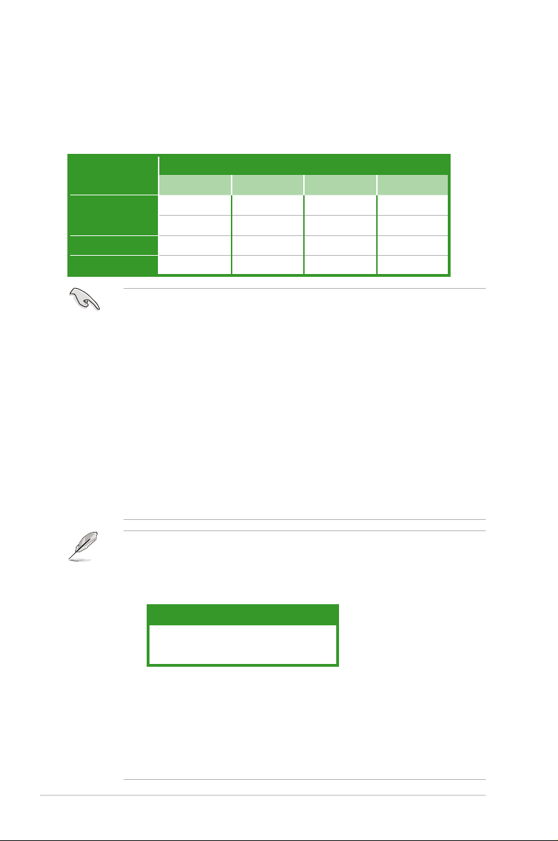
1.7.2 Memory congurations
You may install 256 MB, 512 MB, 1 GB, and 2 GB unbuffered non-ECC DDR2
DIMMs into the DIMM sockets.
Recommended Memory Congurations
Mode
Single-Channel
Dual-channel (1) Populated — Populated —
Dual-channel (2) Populated Populated Populated Populated
• You may install varying memory sizes in Channel A and Channel B. The
• Always install DIMMs with the same CAS latency. For optimum compatibility,
• If you install four 1 GB memory modules, the system may only recognize less
• If you install Windows
• This motherboard does not support memory modules made up of 128 Mb
DIMM_A1 DIMM_A2 DIMM_B1 DIMM_B2
— — Populated —
Populated — — —
system maps the total size of the lower-sized channel for the dual-channel
conguration. Any excess memory from the higher-sized channel is then
mapped for single-channel operation.
it is recommended that you obtain memory modules from the same vendor.
than 3GB because the address space is reserved for other critical functions.
This limitation appears on Windows® XP/Vista 32-bit operation system which
does not support Physical Address Extension (PAE).
less than 3GB is recommended.
chips.
Sockets
®
XP/Vista 32-bit operation system, a total memory of
Notes on memory limitations
• Due to chipset limitation, this motherboard can only support up to
8 GB on the operating systems listed below. You may install a maximum of
2 GB DIMMs on each slot.
64-bit
Windows® XP Professional x64 Edition
Windows® Vista x64 Edition
• Some old-version DDR2-800 DIMMs may not match Intel®’s
On-Die-Termination (ODT) requirement and will automatically downgrade
to run at DDR2-667. If this happens, contact your memory vendor to check
the ODT value.
• Due to chipset limitation, DDR2-800 with CL=4 will be downgraded to run
at DDR2-667 by default setting. If you want to operate with lower latency,
adjust the memory timing manually.
1-18 Chapter1: Product introduction
Loading…
Motherboard
Table of contents
Document Outline
- Notices
- Safety information
- P5K-VM specifications summary
- Product introduction
- 1.1 Welcome!
- 1.2 Package contents
- 1.3 Special features
- 1.3.1 Product highlights
- 1.3.2 ASUS AI Lifestyle features 
- 1.3.3 ASUS Stylish features
- 1.3.4 ASUS Intelligent Overclocking features
- 1.4 Before you proceed
- 1.5 Motherboard overview
- 1.5.1 Placement direction
- 1.5.2 Screw holes
- 1.5.3 Motherboard layout
- 1.6 Central Processing Unit (CPU)
- 1.6.1 Installing the CPU
- 1.6.2 Installing the CPU heatsink and fan
- 1.6.3 Uninstalling the CPU heatsink and fan
- 1.7 System memory
- 1.7.1 Overview
- 1.7.2 Memory configurations
- 1.7.3 Installing a DIMM
- 1.7.4 Removing a DIMM
- 1.8 Expansion slots
- 1.8.1 Installing an expansion card
- 1.8.2 Configuring an expansion card
- 1.8.3 Interrupt assignments
- 1.8.4 PCI slots
- 1.8.5 PCI Express x4 slot
- 1.8.6 PCI Express x16 slot
- 1.9 Jumper
- 1.10 Connectors
- 1.10.1 Rear panel connectors
- 1.10.2 Internal connectors
- BIOS setup
- 2.1 Managing and updating your BIOS
- 2.1.1 ASUS Update utility
- 2.1.2 Creating a bootable floppy disk
- 2.1.3 ASUS EZ Flash 2 utility
- 2.1.4 AFUDOS utility
- 2.1.5 ASUS CrashFree BIOS 3 utility
- 2.2 BIOS setup program
- 2.2.1 BIOS menu screen
- 2.2.2 Menu bar
- 2.2.3 Navigation keys
- 2.2.4 Menu items
- 2.2.5 Sub-menu items
- 2.2.6 Configuration fields
- 2.2.7 Pop-up window
- 2.2.8 Scroll bar
- 2.2.9 General help
- 2.3 Main menu
- 2.3.1 System Time [xx:xx:xx]
- 2.3.2 System Date [Day xx/xx/xxxx]
- 2.3.3 Legacy Diskette A [1.44M, 3.5 in.]
- 2.3.4 SATA 1~4; PATA Primary Master/Slave
- 2.3.5 IDE Configuration
- 2.3.6 System Information
- 2.4 Advanced menu
- 2.4.1 Jumperfree Configuration
- 2.4.2 USB Configuration
- 2.4.3 CPU Configuration
- 2.4.4 Chipset
- 2.4.5 OnBoard Devices Configuration
- 2.4.6 PCIPnP
- 2.5 Power menu
- 2.5.1 Suspend Mode [Auto]
- 2.5.2 Repost Video on S3 Resume [Disabled]
- 2.5.3 ACPI Version [Disabled]
- 2.5.4 ACPI APIC Support [Enabled]
- 2.5.5 APM Configuration
- 2.5.6 Hardware Monitor
- 2.6 Boot menu
- 2.6.1 Boot Device Priority
- 2.6.2 Boot Settings Configuration
- 2.6.3 Security
- 2.7 Tools menu
- 2.7.1 ASUS EZ Flash 2
- 2.7.2 AI Net 2
- 2.8 Exit menu
- Software support
- 5.1 Installing an operating system
- 5.2 Support CD information
- 5.2.1 Running the support CD
- 5.2.2 Drivers menu
- 5.2.3 Utilities menu
- 5.2.4 Manual menu
- 5.2.5 ASUS Contact information
- 5.2.6 Other information
View the manual for the Asus P5K-VM here, for free. This user manual comes under the category motherboards and has been rated by 3 people with an average of a 9. This manual is available in the following languages: English. Do you have a question about the Asus P5K-VM?
Ask your question here
Frequently asked questions
Can’t find the answer to your question in the manual? You may find the answer to your question in the FAQs about the Asus P5K-VM below.
What is the width of the Asus P5K-VM?
The Asus P5K-VM has a width of 244 mm.
What is the depth of the Asus P5K-VM?
The Asus P5K-VM has a depth of 244 mm.
Is the manual of the Asus P5K-VM available in English?
Yes, the manual of the Asus P5K-VM is available in English .
Is your question not listed? Ask your question here
Manufacturer:ASUS
Category:Computers & Peripherals
Device:ASUS P5K-VM
Name:New_SSD_List
Pages:1
Size:18.19 KB
Manufacturer:ASUS
Category:Computers & Peripherals
Device:ASUS P5K-VM
Name:Motherboard Installation Guide (Simplified Chinese)
Language:中文(简体)
Pages:44
Size:1.88 MB
Manufacturer:ASUS
Category:Computers & Peripherals
Device:ASUS P5K-VM
Name:Motherboard Installation Guide (Traditional Chinese)
Language:中文(简体)中文(繁體)
Pages:44
Size:2.02 MB
Manufacturer:ASUS
Category:Computers & Peripherals
Device:ASUS P5K-VM
Name:Motherboard Installation Guide (Simplified Chinese)
Language:中文中文(简体)
Version:C4204
Pages:44
Size:1.88 MB
Manufacturer:ASUS
Category:Computers & Peripherals
Device:ASUS P5K-VM
Name:Motherboard Installation Guide (Traditional Chinese)
Language:中文中文(繁體)
Version:T4204
Pages:44
Size:2.02 MB
Manufacturer:ASUS
Category:Computers & Peripherals
Device:ASUS P5K-VM
Name:Motherboard Installation Guide (Multiple Languages)
Language:Multilingual
Pages:721
Size:43.88 MB
Manufacturer:ASUS
Category:Computers & Peripherals
Device:ASUS P5K-VM
Name:Motherboard Installation Guide (Multiple Languages)
Version:Q4204
Pages:721
Size:43.88 MB
Manufacturer:ASUS
Category:Computers & Peripherals
Device:ASUS P5K-VM
Name:Motherboard Installation Guide (French)
Language:Français
Version:QF4204
Pages:40
Size:1.64 MB
Manufacturer:ASUS
Category:Computers & Peripherals
Device:ASUS P5K-VM
Name:Motherboard Installation Guide (German)
Language:Deutsch
Version:QG4204
Pages:40
Size:1.65 MB
Manufacturer:ASUS
Category:Computers & Peripherals
Device:ASUS P5K-VM
Name:Motherboard Installation Guide (Japanese)
Language:日本語
Version:QJ4204
Pages:40
Size:1.73 MB
Manufacturer:ASUS
Category:Computers & Peripherals
Device:ASUS P5K-VM
Name:User’s manual(Japanese)
Language:日本語
Version:J3279b
Pages:98
Size:2.34 MB
Manufacturer:ASUS
Category:Computers & Peripherals
Device:ASUS P5K-VM
Name:User’s manual(Traditional Chinese)
Language:中文(繁體)
Pages:100
Size:2.12 MB
Manufacturer:ASUS
Category:Computers & Peripherals
Device:ASUS P5K-VM
Name:User’s manual(Simplified Chinese)
Language:中文(简体)
Pages:100
Size:1.99 MB
Manufacturer:ASUS
Category:Computers & Peripherals
Device:ASUS P5K-VM
Name:User’s manual(Traditional Chinese)
Language:中文中文(繁體)
Version:T3172
Pages:100
Size:2.12 MB
Manufacturer:ASUS
Category:Computers & Peripherals
Device:ASUS P5K-VM
Name:User’s manual(Simplified Chinese)
Language:中文中文(简体)
Version:C3172
Pages:100
Size:1.99 MB
Manufacturer:ASUS
Category:Computers & Peripherals
Device:ASUS P5K-VM
Name:User’s manual(Simplified Chinese)
Language:中文(简体)
Pages:100
Size:2.05 MB
Manufacturer:ASUS
Category:Computers & Peripherals
Device:ASUS P5K-VM
Name:User’s manual(Simplified Chinese)
Language:中文中文(简体)
Version:C3172
Pages:100
Size:2.05 MB
Manufacturer:ASUS
Category:Computers & Peripherals
Device:ASUS P5K-VM
Name:User’s manual(Traditional Chinese)
Language:中文(繁體)
Pages:100
Size:2.18 MB
Manufacturer:ASUS
Category:Computers & Peripherals
Device:ASUS P5K-VM
Name:User’s manual(Traditional Chinese)
Language:中文中文(繁體)
Version:T3172
Pages:100
Size:2.18 MB
Manufacturer:ASUS
Category:Computers & Peripherals
Device:ASUS P5K-VM
Name:User’s manual(Japanese)
Language:日本語
Version:J3279
Pages:98
Size:2.34 MB
Manufacturer:ASUS
Category:Computers & Peripherals
Device:ASUS P5K-VM
Name:Manual
Language:中文中文(繁體)
Version:T3172
Pages:100
Size:2.18 MB
Manufacturer:ASUS
Category:Computers & Peripherals
Device:ASUS P5K-VM
Name:Manual
Language:中文中文(简体)
Version:C3172
Pages:100
Size:2.05 MB
Manufacturer:ASUS
Category:Computers & Peripherals
Device:ASUS P5K-VM
Name:User’s manual(English)
Language:English
Version:E3279
Pages:98
Size:1.82 MB
Manufacturer:ASUS
Category:Computers & Peripherals
Device:ASUS P5K-VM
Name:User’s Manual
Language:English
Version:e3172
Pages:98
Size:1.80 MB
Manufacturer:ASUS
Category:Computers & Peripherals
Device:ASUS P5K-VM
Name:Motherboard DIY Troubleshooting Guide (Traditional Chinese version)
Language:中文(繁體)
Pages:8
Size:2.67 MB
Manufacturer:ASUS
Category:Computers & Peripherals
Device:ASUS P5K-VM
Name:Motherboard DIY Troubleshooting Guide (Traditional Chinese version)
Language:中文中文(繁體)
Version:T2437
Pages:8
Size:2.67 MB