

To reduce the impacts on global warming, the packaging materials of this product
are recyclable and reusable. GIGABYTE works with you to protect the environment.
For more product details, please visit GIGABYTE’s website.
B450 AORUS ELITE
User’s Manual
Rev. 1002
12ME-B45ARSE-1002R
Copyright
© 2018 GIGA-BYTE TECHNOLOGY CO., LTD. All rights reserved.
The trademarks mentioned in this manual are legally registered to their respective owners.
Disclaimer
Information in this manual is protected by copyright laws and is the property of GIGABYTE.
Changes to the specications and features in this manual may be made by GIGABYTE without prior notice.
No part of this manual may be reproduced, copied, translated, transmitted, or published in any form or
by any means without GIGABYTE’s prior written permission.
In order to assist in the use of this product, carefully read the User’s Manual.
For product-related information, check on our website at: https://www.gigabyte.com
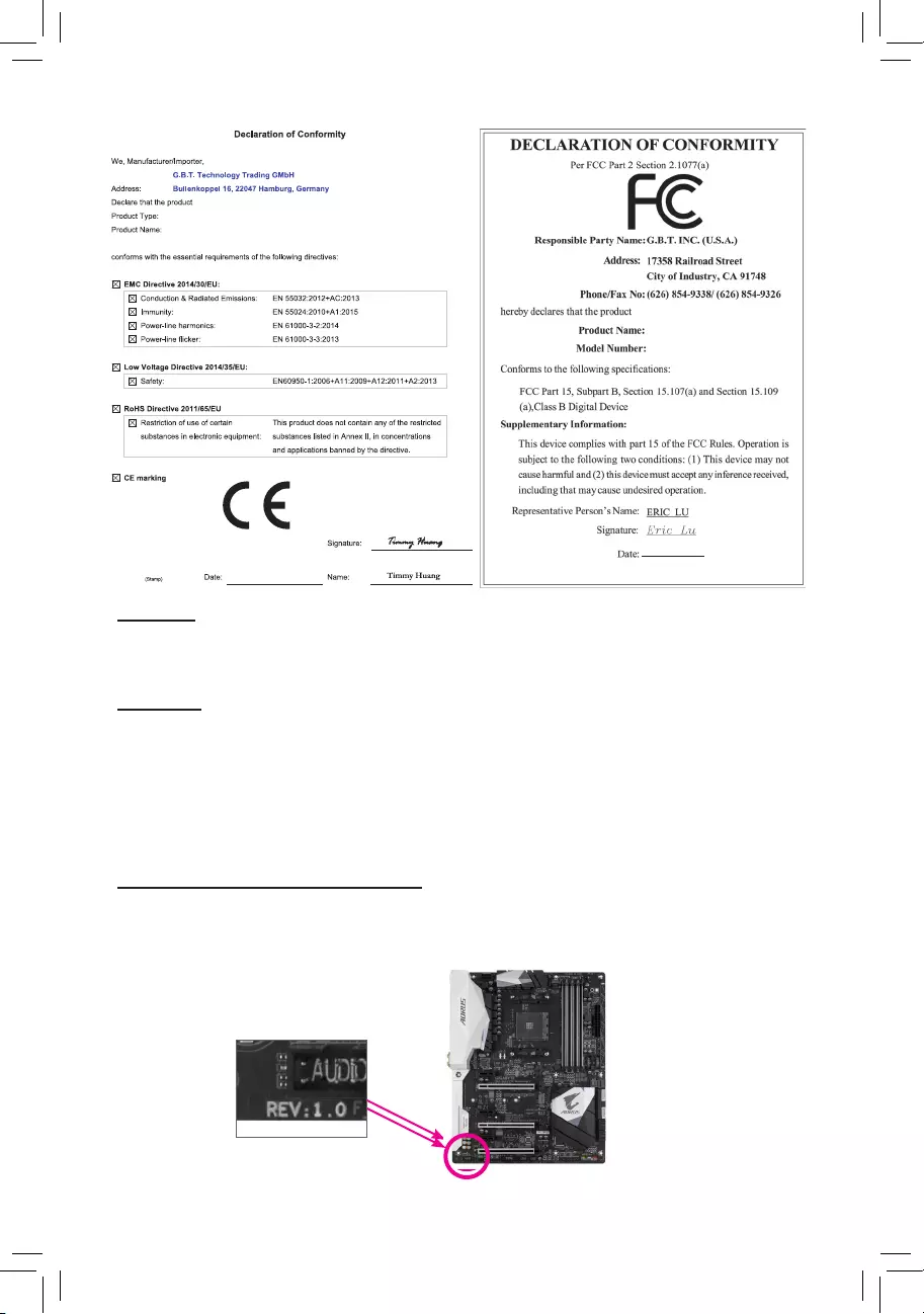
Identifying Your Motherboard Revision
The revision number on your motherboard looks like this: «REV: X.X.» For example, «REV: 1.0″ means
the revision of the motherboard is 1.0. Check your motherboard revision before updating motherboard
BIOS, drivers, or when looking for technical information.
Example:
Motherboard
B450 AORUS ELITE
Jul. 28, 2018
Jul. 28, 2018
Motherboard
B450 AORUS ELITE

— 3 —
Table of Contents
B450 AORUS ELITE Motherboard Layout …………………………………………………………….4
Chapter 1 Hardware Installation ………………………………………………………………………….5
1-1 Installation Precautions ………………………………………………………………………… 5
1-2 ProductSpecications ………………………………………………………………………….. 6
1-3 Installing the CPU ……………………………………………………………………………….. 9
1-4 Installing the Memory …………………………………………………………………………… 9
1-5 Installing an Expansion Card ………………………………………………………………. 10
1-6 Back Panel Connectors ………………………………………………………………………. 10
1-7 Internal Connectors ……………………………………………………………………………. 12
Chapter 2 BIOS Setup ……………………………………………………………………………………..22
2-1 Startup Screen ………………………………………………………………………………….. 22
2-2 The Main Menu …………………………………………………………………………………. 23
2-3 M.I.T. ……………………………………………………………………………………………….. 24
2-4 System …………………………………………………………………………………………….. 28
2-5 BIOS ………………………………………………………………………………………………… 29
2-6 Peripherals ……………………………………………………………………………………….. 32
2-7 Chipset …………………………………………………………………………………………….. 34
2-8 Power ………………………………………………………………………………………………. 36
2-9 Save & Exit ……………………………………………………………………………………….. 38
Chapter 3 Appendix …………………………………………………………………………………………39
3-1 ConguringaRAIDSet ………………………………………………………………………. 39
3-2 DriversInstallation ……………………………………………………………………………… 41
Regulatory Statements …………………………………………………………………………………. 42
Contact Us …………………………………………………………………………………………………. 44
— 4 —
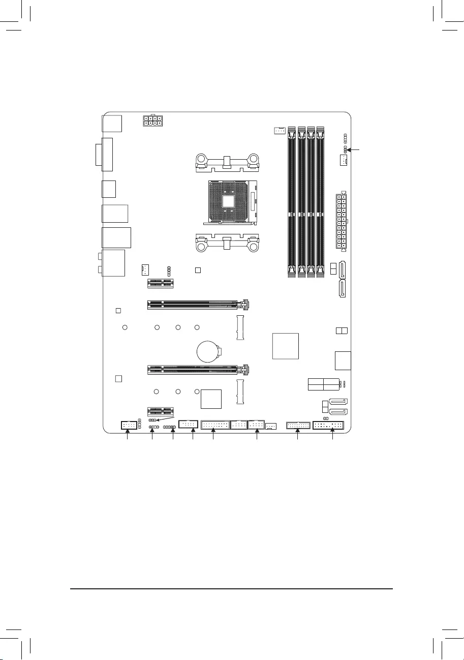
B450 AORUS ELITE Motherboard Layout
* The box contents above are for reference only and the actual items shall depend on the product package you obtain.
The box contents are subject to change without notice.
CPU DRAM
VGA BOOT
Socket AM4
AMDB450
R_USB30
CPU_FAN
ATX_12V
ATX
F_AUDIO
AUDIO
PCIEX4
DDR4_2
DDR4_1
DDR4_4
DDR4_3
BAT
F_PANEL
PCIEX1_2
CLR_CMOS
CODEC
M_BIOS
PCIEX1_1
PCIEX16
SPDIF_O
B450 AORUS ELITE
DVI
KB_MS_USB
HDMI
USB_LAN
SATA3
iTE®
Super I/O
F_USB2
LED_C
SYS_FAN1
TPM
M2A_SOCKET
Realtek®
GbE LAN
2
3
F_USB30
42
6080
110
LED_CPU
SYS_FAN2
42
6080
M2B_SOCKET
F_USB1
D_LED1
DLED_V_SW1
D_LED2
DLED_V_SW2
ASATA3 1 0
Box Contents
5B450 AORUS ELITE Motherboard 5Two SATA cables
5Motherboard driver disk 5M.2 screw(s)/M.2 standoff(s)
5User’s Manual
SATA3
0 1
SYS_FAN3
COMA

Chapter 1 Hardware Installation
1-1 Installation Precautions
The motherboard contains numerous delicate electronic circuits and components which can become
damagedasaresultofelectrostaticdischarge(ESD).Priortoinstallation,carefullyreadtheuser’s
manual and follow these procedures:
•Prior to installation, make sure the chassis is suitable for the motherboard.
•Prior to installation, do not remove or break motherboard S/N (Serial Number) sticker or
warranty sticker provided by your dealer. These stickers are required for warranty validation.
•Always remove the AC power by unplugging the power cord from the power outlet before
installing or removing the motherboard or other hardware components.
•Whenconnectinghardwarecomponentstotheinternalconnectorsonthemotherboard,make
sure they are connected tightly and securely.
•Whenhandlingthemotherboard,avoidtouchinganymetalleadsorconnectors.
•It is best to wear an electrostatic discharge (ESD) wrist strap when handling electronic
componentssuchasamotherboard,CPUormemory.IfyoudonothaveanESDwriststrap,
keepyourhandsdryandrsttouchametalobjecttoeliminatestaticelectricity.
•Prior to installing the motherboard, please have it on top of an antistatic pad or within an
electrostatic shielding container.
•Before connecting or unplugging the power supply cable from the motherboard, make sure
the power supply has been turned off.
•Before turning on the power, make sure the power supply voltage has been set according to
the local voltage standard.
•Before using the product, please verify that all cables and power connectors of your hardware
components are connected.
•To prevent damage to the motherboard, do not allow screws to come in contact with the
motherboard circuit or its components.
•Make sure there are no leftover screws or metal components placed on the motherboard or
within the computer casing.
•Donotplacethecomputersystemonanunevensurface.
•Donotplacethecomputersysteminahigh-temperatureorwetenvironment.
•Turning on the computer power during the installation process can lead to damage to system
components as well as physical harm to the user.
•If you are uncertain about any installation steps or have a problem related to the use of the
product,pleaseconsultacertiedcomputertechnician.
•If you use an adapter, extension power cable, or power strip, ensure to consult with its installation
and/or grounding instructions.
— 5 —
1-2 ProductSpecications
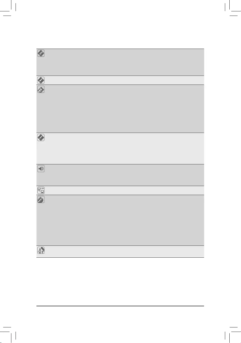
CPU AM4 Socket:
- AMDRyzen™ 2nd Generation processors
- AMDRyzen™ with Radeon™ Vega Graphics processors
- AMDRyzen™ 1st Generation processors
(Go to GIGABYTE’s website for the latest CPU support list.)
Chipset AMDB450
Memory 4xDDR4DIMMsocketssupportingupto64GBofsystemmemory
Dualchannelmemoryarchitecture
SupportforDDR42933/2667/2400/2133MHzmemorymodules
SupportforECCUn-bufferedDIMM1Rx8/2Rx8memorymodules(operate in
non-ECC mode)
Supportfornon-ECCUn-bufferedDIMM1Rx8/2Rx8/1Rx16memorymodules
SupportforExtremeMemoryProle(XMP)memorymodules
(Go to GIGABYTE’s website for the latest supported memory speeds and memory
modules.)
Onboard
Graphics (Note)
Integrated Graphics Processor:
- 1xDVI-Dport,supportingamaximumresolutionof1920×1200@60Hz
* TheDVI-DportdoesnotsupportD-Subconnectionbyadapter.
- 1xHDMIport,supportingamaximumresolutionof4096×2160@60(Note)Hz
* SupportforHDMI2.0versionandHDCP2.2.(Note)
— Maximum shared memory of 16 GB
Audio Realtek® ALC892 codec
HighDenitionAudio
2/4/5.1/7.1-channel
SupportforS/PDIFOut
LAN Realtek® GbE LAN chip (10/100/1000 Mbit)
Expansion Slots 1 x PCI Express x16 slot, running at x16 (PCIEX16) (Note)
* For optimum performance, if only one PCI Express graphics card is to be installed,
be sure to install it in the PCIEX16 slot.
(The PCIEX16 slot conforms to PCI Express 3.0 standard.)
1 x PCI Express x16 slot, running at x4 (PCIEX4)
* The PCIEX4 slot shares bandwidth with the PCIEX1_2 slot. The PCIEX4 slot operates
at up to x2 mode when the PCIEX1_2 slot is populated. The PCIEX4 slot operates
at up to x4 mode when the PCIEX1_2 is empty.
2 x PCI Express x1 slots
(The PCIEX4 and PCIEX1 slots conform to PCI Express 2.0 standard.)
Multi-Graphics
Technology SupportforAMDQuad-GPUCrossFire™and2-WayAMDCrossFire™ technologies
(Note) Actual support may vary by CPU.
— 6 —
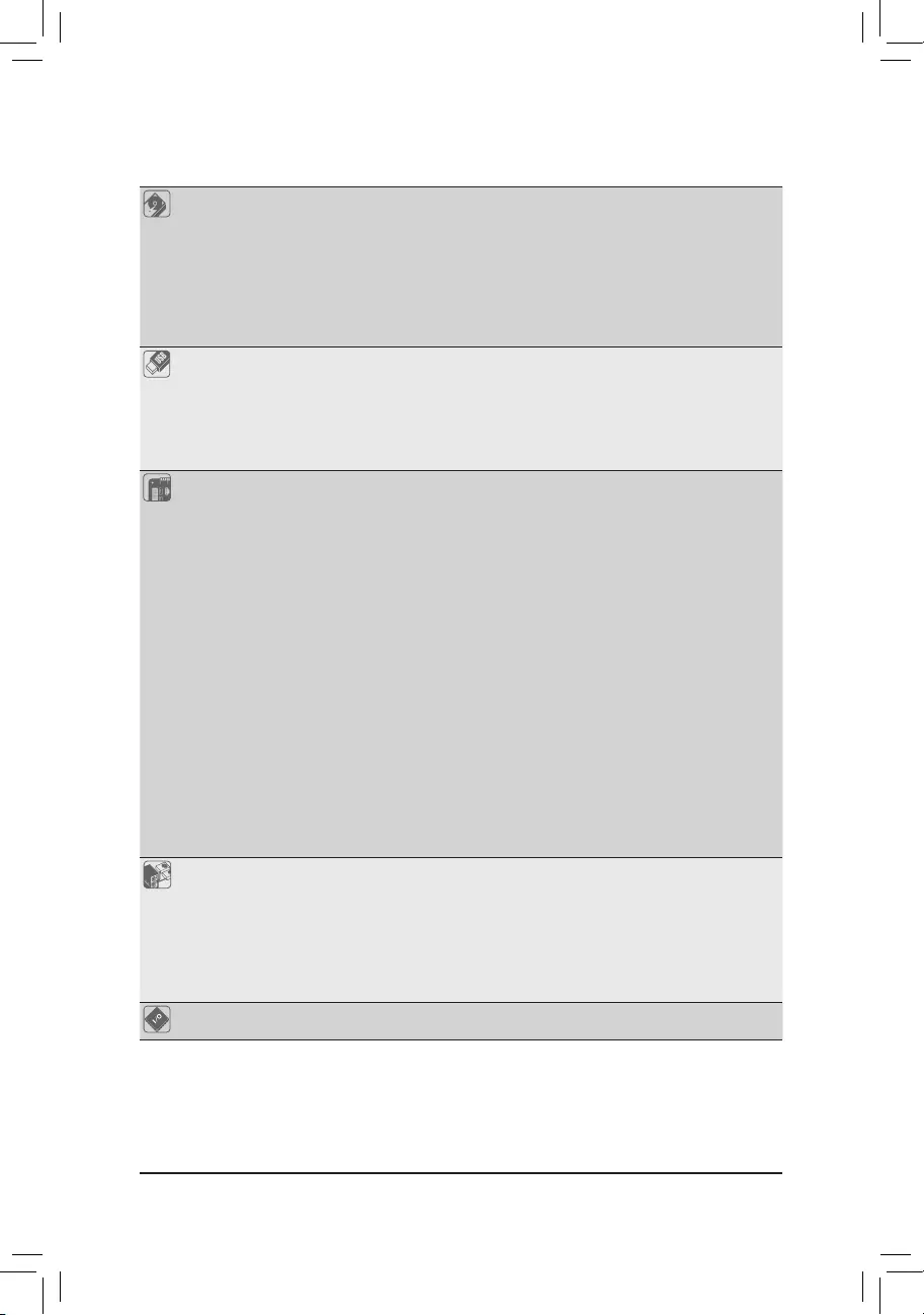
Storage Interface — 1 x M.2 connector (Socket 3, M key, type 2242/2260/2280/22110 SATA and
PCIe3.0x4/x2SSDsupport)(M2A_SOCKET)
- 1xM.2connector(Socket3,Mkey,type2242/2260/2280PCIe3.0x2SSD
support)(M2B_SOCKET)
6 x SATA 6Gb/s connectors
SupportforRAID0,RAID1,andRAID10
* Refer to «1-7 Internal Connectors,» for the installation notices for the M.2 and SATA
connectors.
USB Chipset:
— 2 x USB 3.1 Gen 1 ports available through the internal USB header
— 8 x USB 2.0/1.1 ports (4 ports on the back panel, 4 ports available through
the internal USB headers)
Integrated in the APU:
— 4 x USB 3.1 Gen 1 ports on the back panel
Internal
Connectors
1 x 24-pin ATX main power connector
1 x 8-pin ATX 12V power connector
2 x M.2 Socket 3 connectors
6 x SATA 6Gb/s connectors
1 x CPU fan header
3 x system fan headers
1xCPUcoolerLEDstrip/RGBLEDstripextensioncableheader
1xRGB(RGBW)LEDstripheader
2xdigitalLEDstripheaders
2xdigitalLEDstrippowerselectjumpers
1 x front panel header
1 x front panel audio header
1xS/PDIFOutheader
1 x USB 3.1 Gen 1 header
2 x USB 2.0/1.1 headers
1 x Trusted Platform Module (TPM) header (2×10 pin, for the GC-TPM2.0 module
only)
1 x serial port header
1 x Clear CMOS jumper
Back Panel
Connectors
1 x PS/2 keyboard/mouse port
1xDVI-Dport
1xHDMIport
4 x USB 3.1 Gen 1 ports
4 x USB 2.0/1.1 ports
1 x RJ-45 port
6 x audio jacks
I/O Controller iTE® I/O Controller Chip
— 7 —
Hardware
Monitor
Voltage detection
Temperature detection
Fan speed detection
Overheating warning
Fan fail warning
Fan speed control
* Whetherthefanspeedcontrolfunctionissupportedwilldependonthecooleryou
install.
BIOS 1x128Mbitash
Use of licensed AMI UEFI BIOS
PnP1.0a,DMI2.7,WfM2.0,SMBIOS2.7,ACPI5.0
Unique Features Support for APP Center
* Available applications in APP Center may vary by motherboard model. Supported
functionsofeachapplicationmayalsovarydependingonmotherboardspecications.
- 3DOSD
- @BIOS
— AutoGreen
— Cloud Station
— EasyTune
— Fast Boot
— Game Boost
— ON/OFF Charge
— RGB Fusion
— Smart Backup
— Smart Keyboard
— Smart TimeLock
- SmartHUD
— Smart Survey
— System Information Viewer
— USB Blocker
SupportforQ-Flash
Support for Xpress Install
Bundled
Software
Norton® Internet Security (OEM version)
Realtek® 8118 Gaming LAN Bandwidth Control Utility
Operating
System SupportforWindows1064-bit
Form Factor ATX Form Factor; 30.5cm x 23.5cm
* GIGABYTEreservestherighttomakeanychangestotheproductspecicationsandproduct-relatedinformationwithout
prior notice.
Please visit GIGABYTE’s website
for support lists of CPU, memory
modules,SSDs,andM.2devices.
Please visit the Support\Utility List
page on GIGABYTE’s website to
download the latest version of apps.
— 8 —

1-3 Installing the CPU
AM4 Socket
A Small Triangle
MarkingDenotesPin
One of the Socket AM4 CPU
A Small Triangle
MarkingDenotesCPU
Pin One
1-4 Installing the Memory
Please visit GIGABYTE’s website for details on hardware installation.
DualChannelMemoryConguration
ThismotherboardprovidesfourmemorysocketsandsupportsDualChannelTechnology.Afterthememory
isinstalled,theBIOSwillautomaticallydetectthespecicationsandcapacityofthememory.EnablingDual
Channel memory mode will double the original memory bandwidth.
The four memory sockets are divided into two channels and each channel has two memory sockets as following:
ChannelA:DDR4_2,DDR4_4
ChannelB:DDR4_1,DDR4_3
Read the following guidelines before you begin to install the memory:
•Make sure that the motherboard supports the memory. It is recommended that memory of the
same capacity, brand, speed, and chips be used.
(Go to GIGABYTE’s website for the latest supported memory speeds and memory modules.)
•Always turn off the computer and unplug the power cord from the power outlet before installing the
memory to prevent hardware damage.
•Memory modules have a foolproof design. A memory module can be installed in only one direction.
If you are unable to insert the memory, switch the direction.
DualChannelMemoryCongurationsTable
DDR4_4 DDR4_2 DDR4_3 DDR4_1
2 Modules — — DS/SS — — DS/SS
DS/SS — — DS/SS — —
4 Modules DS/SS DS/SS DS/SS DS/SS
(SS=Single-Sided,DS=Double-Sided,»--«=NoMemory)
Read the following guidelines before you begin to install the CPU:
•Make sure that the motherboard supports the CPU.
(Go to GIGABYTE’s website for the latest CPU support list.)
•Always turn off the computer and unplug the power cord from the power outlet before installing the
CPU to prevent hardware damage.
•Locate the pin one of the CPU. The CPU cannot be inserted if oriented incorrectly.
•Apply an even and thin layer of thermal grease on the surface of the CPU.
•DonotturnonthecomputeriftheCPUcoolerisnotinstalled,otherwiseoverheatinganddamage
of the CPU may occur.
•SettheCPUhostfrequencyinaccordancewiththeCPUspecications.Itisnotrecommended
thatthesystembusfrequencybesetbeyondhardwarespecicationssinceitdoesnotmeetthe
standard requirements for the peripherals. If you wish to set the frequency beyond the standard
specications,pleasedosoaccordingtoyourhardwarespecicationsincludingtheCPU,graphics
card, memory, hard drive, etc.
Installing the CPU
Locate the pin one (denoted by a small triangle) of the CPU socket and the CPU.
— 9 —
1-5 Installing an Expansion Card
Read the following guidelines before you begin to install an expansion card:
•Make sure the motherboard supports the expansion card. Carefully read the manual that came
with your expansion card.
•Always turn off the computer and unplug the power cord from the power outlet before installing an
expansion card to prevent hardware damage.
1-6 Back Panel Connectors
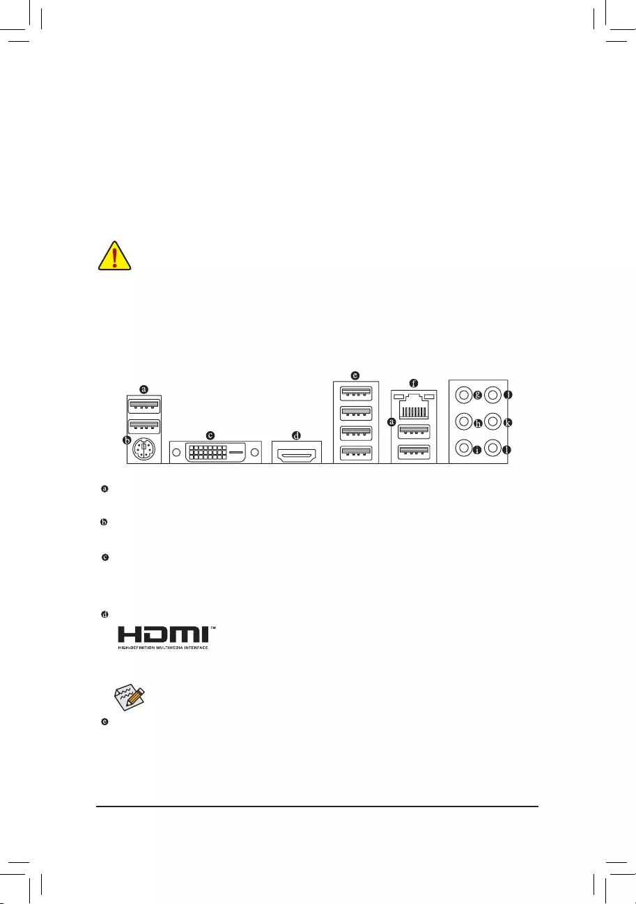
USB 2.0/1.1 Port
TheUSBportsupportstheUSB2.0/1.1specication.UsethisportforUSBdevices.
PS/2 Keyboard/Mouse Port
Use this port to connect a PS/2 mouse or keyboard.
DVI-D Port (Note 1)
TheDVI-DportconformstotheDVI-Dspecicationandsupportsamaximumresolutionof1920×1200@60Hz
(theactualresolutionssupporteddependonthemonitorbeingused).ConnectamonitorthatsupportsDVI-D
connection to this port.
HDMI Port
TheHDMIportsupportsHDCP2.2(Note 2)andDolbyTrueHDandDTSHDMaster
Audioformats.Italsosupportsupto192KHz/24bit8-channelLPCMaudiooutput.
YoucanusethisporttoconnectyourHDMI-supportedmonitor.Themaximumsupportedresolutionis
4096×2160@60Hz(Note 2), but the actual resolutions supported are dependent on the monitor being used.
USB 3.1 Gen 1 Port
TheUSB3.1Gen1portsupportstheUSB3.1Gen1specicationandiscompatibletotheUSB2.0
specication.UsethisportforUSBdevices.
(Note1) TheDVI-DportdoesnotsupportD-Subconnectionbyadapter.
(Note 2) Actual support may vary by CPU.
AfterinstallingtheHDMIdevice,makesuretosetthedefaultsoundplaybackdevicetoHDMI.(The
item name may differ depending on your operating system.)
DuetoCPUlimitations,readthefollowingguidelinesbeforeinstallingthememoryinDualChannelmode.
1. DualChannelmodecannotbeenabledifonlyonememorymoduleisinstalled.
2. WhenenablingDualChannelmodewithtwoorfourmemorymodules,itisrecommendedthatmemory
of the same capacity, brand, speed, and chips be used. For optimum performance, when enabling
DualChannelmodewithtwomemorymodules,werecommendthatyouinstallthemintheDDR4_1
andDDR4_2sockets.
— 10 —
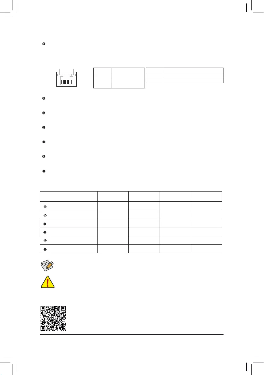
RJ-45 LAN Port
The Gigabit Ethernet LAN port provides Internet connection at up to 1 Gbps data rate. The following
describesthestatesoftheLANportLEDs.
ActivityLED
Connection/
SpeedLED
LAN Port
ActivityLED:Connection/SpeedLED:
State Description
Orange 1 Gbps data rate
Green 100 Mbps data rate
Off 10 Mbps data rate
Center/Subwoofer Speaker Out (Orange)
Use this audio jack to connect center/subwoofer speakers.
Rear Speaker Out (Black)
This jack can be used to connect rear speakers.
Side Speaker Out (Gray)
Use this audio jack to connect side speakers.
Line In (Blue)
The line in jack. Use this audio jack for line in devices such as an optical drive, walkman, etc.
Line Out/Front Speaker Out(Green)
The line out jack. .
Mic In (Pink)
The Mic in jack.
PleasevisitGIGABYTE’swebsitefordetailsonconguringtheaudiosoftware.
•Whenremovingthecableconnectedtoabackpanelconnector,rstremovethecablefromyour
device and then remove it from the motherboard.
•Whenremovingthecable,pullitstraightoutfromtheconnector.Donotrockitsidetosidetoprevent
an electrical short inside the cable connector.
ToenableorconguretheaudioamplifyingfunctionfortheLineoutjack,pleaseaccesstheHD
Audio Manager application.
AudioJackCongurations:
Jack Headphone/
2-channel 4-channel 5.1-channel 7.1-channel
Center/Subwoofer Speaker Out a a
Rear Speaker Out a a a
Side Speaker Out a
Line In
Line Out/Front Speaker Out a a a a
Mic In
State Description
Blinking Datatransmissionorreceivingisoccurring
Off No data transmission or receiving is occurring
— 11 —
1-7 Internal Connectors
Read the following guidelines before connecting external devices:
•First make sure your devices are compliant with the connectors you wish to connect.
•Before installing the devices, be sure to turn off the devices and your computer. Unplug the power
cord from the power outlet to prevent damage to the devices.
•After installing the device and before turning on the computer, make sure the device cable has
been securely attached to the connector on the motherboard.
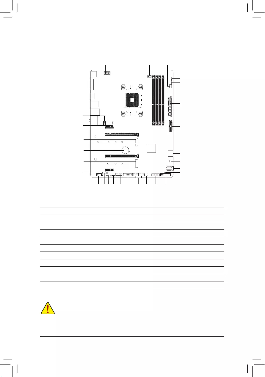
1) ATX _12V
2) ATX
3) CPU_FAN
4) SYS_FAN1/2/3
5) LED_CPU
6) LED_C
7) D_LED1/D_LED2
 DLED_V_SW1/DLED_V_SW2
9) ASATA3 0/1
10) SATA3 0/1/2/3
11) M2A_SOCKET/M2B_SOCKET
12) SPDIF_O
13) F_PANEL
14) F_ AUDIO
15) BAT
16) CLR_CMOS
17) F_USB30
18) F_USB1/F_USB2
19) COMA
20) TPM
21) CPU/DRAM/VGA/BOOT
14
17
6
11
9
18
16
2
3
10
14 20 134
4
8
7 19
11
8
12
5
7
15 10
21
— 12 —
131
2412
ATX
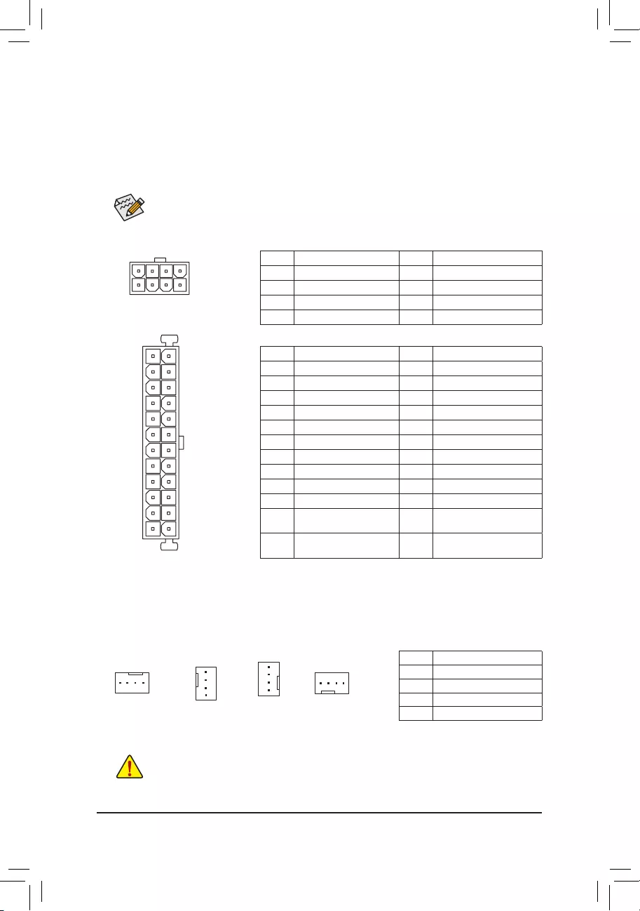
1/2) ATX_12V/ATX (2×4 12V Power Connector and 2×12 Main Power Connector)
Withtheuseofthepowerconnector,thepowersupplycansupplyenoughstablepowertoallthecomponents
onthemotherboard.Beforeconnectingthepowerconnector,rstmakesurethepowersupplyisturned
off and all devices are properly installed. The power connector possesses a foolproof design. Connect the
power supply cable to the power connector in the correct orientation.
The 12V power connector mainly supplies power to the CPU. If the 12V power connector is not connected,
the computer will not start.
To meet expansion requirements, it is recommended that a power supply that can withstand high
powerconsumptionbeused(500Worgreater).Ifapowersupplyisusedthatdoesnotprovidethe
required power, the result can lead to an unstable or unbootable system.
ATX:
Pin No. Denition Pin No. Denition
1 3.3V 13 3.3V
2 3.3V 14 -12V
3GND 15 GND
4 +5V 16 PS_ON (soft On/Off)
5GND 17 GND
6 +5V 18 GND
7GND 19 GND
8 Power Good 20 NC
9 5VSB (stand by +5V) 21 +5V
10 +12V 22 +5V
11 +12V (Only for 2×12-pin
ATX)
23 +5V (Only for 2×12-pin ATX)
12 3.3V (Only for 2×12-pin
ATX)
24 GND(Onlyfor2×12-pinATX)
ATX_12V:
Pin No. Denition Pin No. Denition
1GND(Onlyfor2×4-pin12V) 5 +12V (Only for 2×4-pin 12V)
2GND(Onlyfor2×4-pin12V) 6 +12V (Only for 2×4-pin 12V)
3GND 7 +12V
4GND 8 +12V
ATX_12V
41
85
3/4) CPU_FAN/SYS_FAN1/2/3 (Fan Headers)
All fan headers on this motherboard are 4-pin. Most fan headers possess a foolproof insertion design.
Whenconnectingafancable,besuretoconnectitinthecorrectorientation(theblackconnectorwireis
the ground wire). The speed control function requires the use of a fan with fan speed control design. For
optimum heat dissipation, it is recommended that a system fan be installed inside the chassis.
•Be sure to connect fan cables to the fan headers to prevent your CPU and system from
overheating. Overheating may result in damage to the CPU or the system may hang.
•Thesefanheadersarenotcongurationjumperblocks.Donotplaceajumpercapontheheaders.
CPU_FAN
SYS_FAN1
1
1Pin No. Denition
1GND
2 Voltage Speed Control
3 Sense
4PWMSpeedControl
SYS_FAN2
1
SYS_FAN3
1
— 13 —
Pin No. Denition
1 12V
2 G
3 R
4 B
1
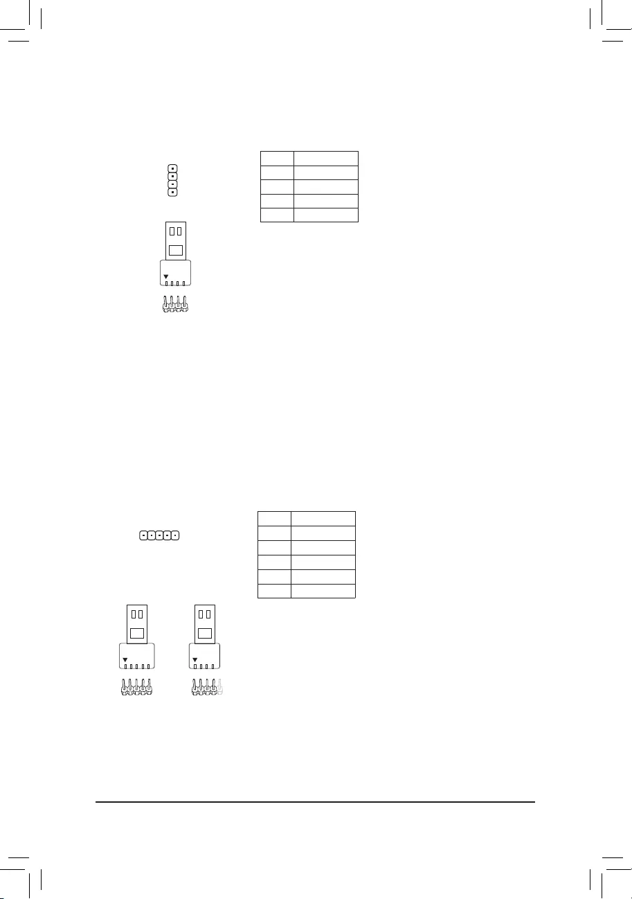
5) LED_CPU (CPU Cooler LED Strip/RGB LED Strip Header)
TheheadercanbeusedtoconnectaCPUcoolerLEDstriporastandard5050RGBLEDstrip(12V/G/R/B),
with maximum power rating of 2A (12V) and maximum length of 2m.
ConnecttheCPUcoolerLEDstrip/RGBLEDstriptotheheader.The
powerpin(markedwithatriangleontheplug)oftheLEDstripmust
be connected to Pin 1 (12V) of this header. Incorrect connection may
leadtothedamageoftheLEDstrip.
LEDStrip
1
12V
6) LED_C (RGB (RGBW) LED Strip Header)
Theheadercanbeusedtoconnectastandard5050RGB(RGBW)LEDstrip(12V/G/R/B/W),withmaximum
power rating of 2A (12V) and maximum length of 2m.
Pin No. Denition
1 12V
2 G
3 R
4 B
5W
F_USB30 F_U
B_
F_ F_
_
B
BS_
B
SB_
B
_S
S_
_
B
_U
_
B
S
123
123
123
123
1
1
1
1
BSS
S
_S
SSU
1 2 3
S3 BSSS
U
__ 3
F_USB3F
S _
S _
S _
SF
B_
B_
F
_0
S
S
_0F
_F
_
_
__B
U
S _S
_ SF_
USB0_B
B_ F_USB3
F_USB303
_
_3U
1
ConnectyourRGB(RGBW)LEDstriptotheheader.Thepowerpin
(markedwithatriangleontheplug)oftheLEDstripmustbeconnected
to Pin 1 (12V) of this header. Incorrect connection may lead to the
damageoftheLEDstrip.
RGBW
LEDStrip
1
12V
RGB
LEDStrip
1
12V
— 14 —
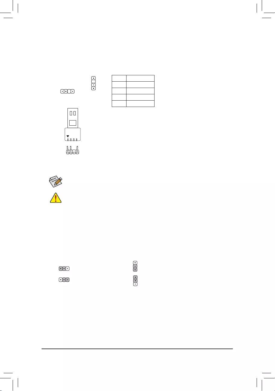
7) D_LED1/D_LED2 (Digital LED Strip Headers)
Theheaderscanbeusedtoconnectastandard5050digitalLEDstrip,withmaximumpowerratingof2A
(12Vor5V)andmaximumlengthof5mormaximumnumberof300LEDs.Thereare12Vand5Vdigital
LEDstrips.BesuretoverifythevoltagerequirementsofyourdigitalLEDstripandsettheDLED_V_SW1
andDLED_V_SW2jumpersaccordingly.
Pin No. Denition
1 V
2D
3 No Pin
4 G
Before installing the devices, be sure to turn off the devices and your computer. Unplug the power
cord from the power outlet to prevent damage to the devices.
Forhowtoturnon/offthelightsoftheLEDstrip,refertotheinstructionsoninChapter2,«BIOS
Setup,» «Peripherals.»
D_LED1 D_LED2
ConnectyourdigitalLEDstriptotheheader.Thereare12Vand5V
digitalLEDstrips.Besuretoverifythevoltagerequirementsofyour
digitalLEDstripandsettheDLED_V_SW1andDLED_V_SW2jumpers
accordingly. The power pin (marked with a triangle on the plug) of the
LEDstripmustbeconnectedtoPin1ofthedigitalLEDstripheader.
IncorrectconnectionmayleadtothedamageoftheLEDstrip.
1
F_USB30 F_U
B_
F_ F_
_
B
BS_
B
SB_
B
_S
S_
_
B
_U
_
B
S
123
123
123
123
1
1
1
1
BSS
S
_S
SSU
1 2 3
S3 BSSS
U
__ 3
F_USB3F
S _
S _
S _
SF
B_
B_
F
_0
S
S
_0F
_F
_
_
__B
U
S _S
_ SF_
USB0_B
B_ F_USB3
F_USB303
_
_3U
F_USB30 F_U
B_
F_ F_
_
B
BS_
B
SB_
B
_S
S_
_
B
_U
_
B
S
123
123
123
123
1
1
1
1
BSS
S
_S
SSU
1 2 3
S3 BSSS
U
__ 3
F_USB3F
S _
S _
S _
SF
B_
B_
F
_0
S
S
_0F
_F
_
_
__B
U
S _S
_ SF_
USB0_B
B_ F_USB3
F_USB303
_
_3U
1
DigitalLED
Strip
1
DLED_V_SW1/DLED_V_SW2 (Digital LED Strip Power Select Jumpers)
ThejumpersallowyoutoselectthesupplyvoltageoftheD_LED1andD_LED2headers.Besureto
verifythevoltagerequirementsofyourdigitalLEDstripandsetthecorrectvoltagewiththisjumperbefore
connection.IncorrectconnectionmayleadtothedamageoftheLEDstrip.
1
1
1-2:5V(Default) 1-2:5V(Default)
2-3: 12V 2-3: 12V
DLED_V_SW1
1
1
DLED_V_SW2
— 15 —
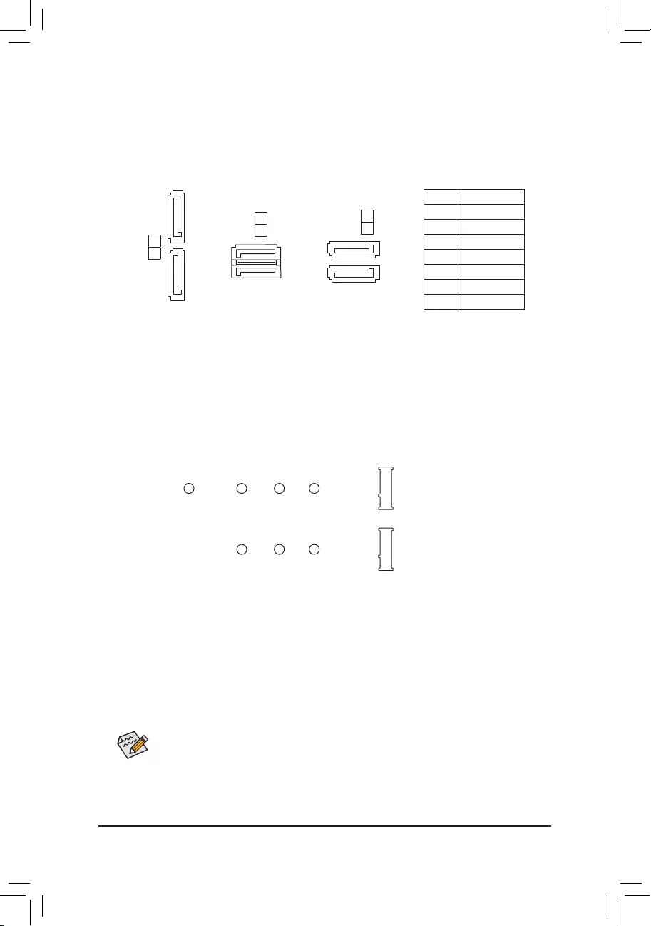
9/10) ASATA3 0/1, SATA 3 0/1/2/3 (SATA 6Gb/s Connectors)
The SATA connectors conform to SATA 6Gb/s standard and are compatible with SATA 3Gb/s and
SATA 1.5Gb/s standard. Each SATA connector supports a single SATA device. The SATA connectors
supportRAID0,RAID1,andRAID10.RefertoChapter3,«ConguringaRAIDSet,»forinstructions
onconguringaRAIDarray.
Pin No. Denition
1GND
2 TXP
3 TXN
4GND
5 RXN
6 RXP
7GND
SATA3 2
3
7
1
71
71
ASATA3 0
1
SATA3 1
0
7
7
1
1
11) M2A_SOCKET/M2B_SOCKET (M.2 Socket 3 Connectors)
TheM.2connectorssupportM.2SATASSDsorM.2PCIeSSDs (Note)andsupportRAIDconguration.
PleasenotethatanM.2PCIeSSDcannotbeusedtocreateaRAIDseteitherwithanM.2SATASSDora
SATAharddrive.TocreateaRAIDarraywithanM.2PCIeSSD,youmustsetupthecongurationinUEFI
BIOSmode.RefertoChapter3,»ConguringaRAIDSet,»forinstructionsonconguringaRAIDarray.
SelecttheproperholefortheM.2SSDtobeinstalledandrefastenthescrewandnut.
F_USB30 F_U
B_
F_ F_
_
B
BS_
B
SB_
B
_S
S_
_
B
_U
_
B
S
123
123
123
123
1
1
1
1
BSS
S
_S
SSU
1 2 3
S3 BSSS
U
__ 3
F_USB3F
S _
S _
S _
SF
B_
B_
F
_0
S
S
_0F
_F
_
_
__B
U
S _S
_ SF_
USB0_B
B_ F_USB3
F_USB303
_
_3U
80110 60 42
F_USB30 F_U
B_
F_ F_
_
B
BS_
B
SB_
B
_S
S_
_
B
_U
_
B
S
123
123
123
123
1
1
1
1
BSS
S
_S
SSU
1 2 3
S3 BSSS
U
__ 3
F_USB3F
S _
S _
S _
SF
B_
B_
F
_0
S
S
_0F
_F
_
_
__B
U
S _S
_ SF_
USB0_B
B_ F_USB3
F_USB303
_
_3U
80 60 42
M2A_SOCKET
M2B_SOCKET
FollowthestepsbelowtocorrectlyinstallanM.2SSDintheM.2connector.
Step 1:
Get a screw and a standoff from the included M.2 screw and standoff packs. Locate the M.2 connector
whereyouwillinstalltheM.2SSD,useascrewdrivertounfastenthescrewontheheatsinkandthen
remove the heatsink.
Step 2:
LocatethepropermountingholefortheM.2SSDtobeinstalledandthentightenthestandoffrst.Insert
theM.2SSDintotheM.2connectoratanangle.
Step 3:
PresstheM.2SSDdownandthensecureitwiththescrew.Replacetheheatsinkandsecureittothe
original hole.
(Note) TheM2B_SOCKETconnectorsupportsonlyPCIeSSDs.
— 16 —
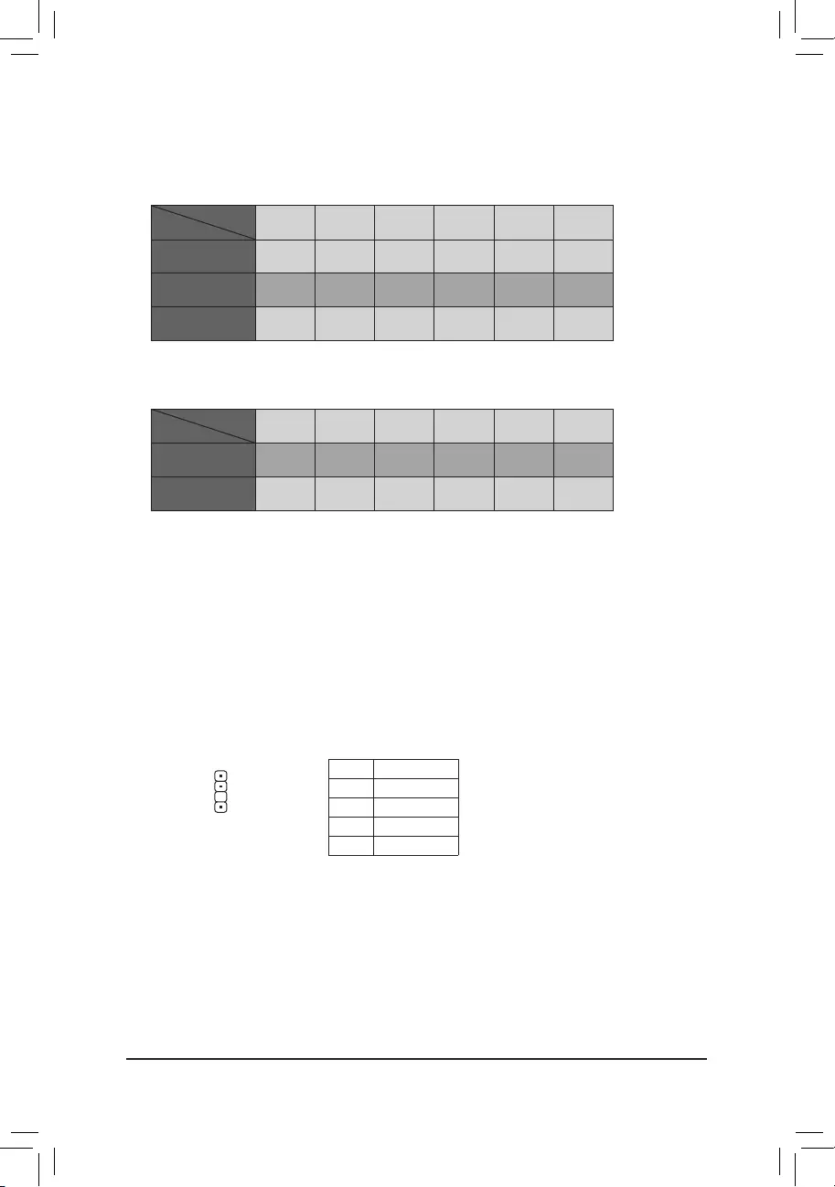
Installation Notices for the M.2 and SATA Connectors:
DuetothelimitednumberoflanesprovidedbytheChipset,theavailabilityoftheSATAconnectorsmay
be affected by the type of device installed in the M.2 connector. Refer to the following table for details.
12) SPDIF_O (S/PDIF Out Header)
ThisheadersupportsdigitalS/PDIFOutandconnectsaS/PDIFdigitalaudiocable(providedbyexpansion
cards) for digital audio output from your motherboard to certain expansion cards like graphics cards and
soundcards.Forexample,somegraphicscardsmayrequireyoutouseaS/PDIFdigitalaudiocablefor
digitalaudiooutputfromyourmotherboardtoyourgraphicscardifyouwishtoconnectanHDMIdisplay
tothegraphicscardandhavedigitalaudiooutputfromtheHDMIdisplayatthesametime.Forinformation
aboutconnectingtheS/PDIFdigitalaudiocable,carefullyreadthemanualforyourexpansioncard.
1
F_USB30 F_U
B_
F_ F_
_
B
BS_
B
SB_
B
_S
S_
_
B
_U
_
B
S
123
123
123
123
1
1
1
1
BSS
S
_S
SSU
1 2 3
S3 BSSS
U
__ 3
F_USB3F
S _
S _
S _
SF
B_
B_
F
_0
S
S
_0F
_F
_
_
__B
U
S _S
_ SF_
USB0_B
B_ F_USB3
F_USB303
_
_3U
Pin No. Denition
15VDUAL
2 No Pin
3SPDIFO
4GND
•M2B_SOCKET:
SATA3 0 SATA3 1 SATA3 2 SATA3 3 ASATA3 0 ASATA3 1
M.2PCIex2SSD*
a a r r a a
NoM.2SSDInstalled aaaaaa
a: Available, r: Not available
* TheM2B_SOCKETconnectorsupportsuptoPCIex2SSDs.
Connector
Type of
M.2SSD
•M2A_SOCKET:
SATA3 0 SATA3 1 SATA3 2 SATA3 3 ASATA3 0 ASATA3 1
M.2SATASSD a a a a r r
M.2PCIeSSD
aaaar r
NoM.2SSDInstalled aaaaaa
a: Available, r: Not available
Connector
Type of
M.2SSD
— 17 —
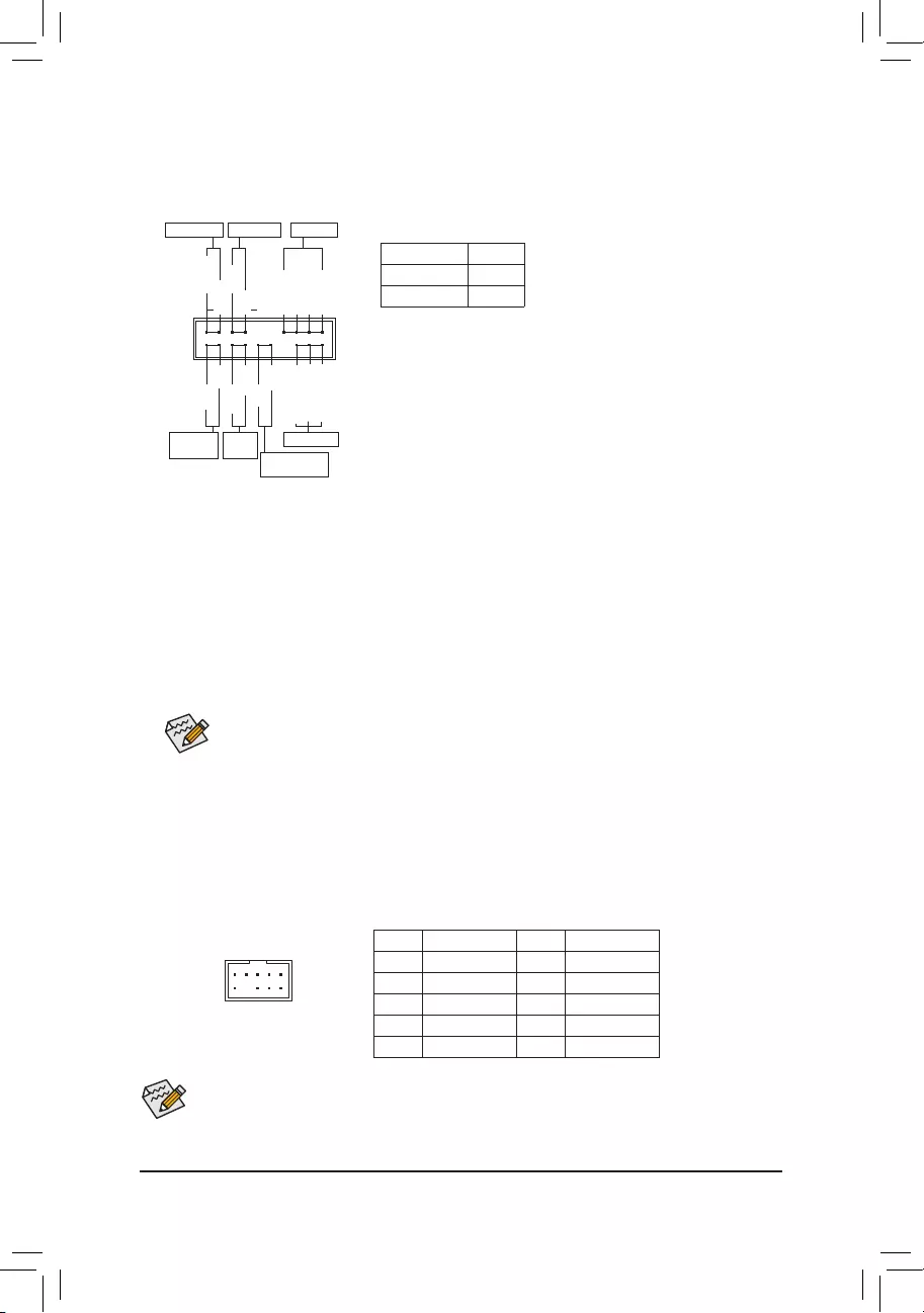
The front panel design may differ by chassis. A front panel module mainly consists of power switch,
resetswitch,powerLED,harddriveactivityLED,speakerandetc.Whenconnectingyourchassis
front panel module to this header, make sure the wire assignments and the pin assignments are
matched correctly.
13) F_PANEL (Front Panel Header)
Connect the power switch, reset switch, speaker, chassis intrusion switch/sensor and system status indicator
on the chassis to this header according to the pin assignments below. Note the positive and negative pins
before connecting the cables.
System Status LED
S0 On
S3/S4/S5 Off
Connects to the power status indicator
onthechassisfrontpanel.TheLEDison
whenthesystemisoperating.TheLEDis
off when the system is in S3/S4 sleep state
or powered off (S5).
•PW (Power Switch, Red):
Connects to the power switch on the chassis front panel. You may
congurethewaytoturnoffyoursystemusingthepowerswitch(refer
to Chapter 2, «BIOS Setup,» «Power,» for more information).
•SPEAK (Speaker, Orange):
Connects to the speaker on the chassis front panel. The system reports
system startup status by issuing a beep code. One single short beep
will be heard if no problem is detected at system startup.
•PLED/PWR_LED (PowerLED,Yellow/Purple):
•HD (HardDriveActivityLED,Blue):
ConnectstotheharddriveactivityLEDonthechassisfrontpanel.TheLEDisonwhentheharddrive
is reading or writing data.
•RES (Reset Switch, Green):
Connects to the reset switch on the chassis front panel. Press the reset switch to restart the computer
ifthecomputerfreezesandfailstoperformanormalrestart.
•CI (Chassis Intrusion Header, Gray):
Connects to the chassis intrusion switch/sensor on the chassis that can detect if the chassis cover has
been removed. This function requires a chassis with a chassis intrusion switch/sensor.
•NC (Orange): No Connection.
14) F_AUDIO (Front Panel Audio Header)
ThefrontpanelaudioheadersupportsHighDenitionaudio(HD).Youmayconnectyourchassisfront
panel audio module to this header. Make sure the wire assignments of the module connector match the
pin assignments of the motherboard header. Incorrect connection between the module connector and the
motherboard header will make the device unable to work or even damage it.
Some chassis provide a front panel audio module that has separated connectors on each wire instead
of a single plug. For information about connecting the front panel audio module that has different wire
assignments, please contact the chassis manufacturer.
F_USB30 F_U
B_
F_ F_
_
B
BS_
B
SB_
B
_S
S_
_
B
_U
_
B
S
123
123
123
123
1
1
1
1
BSS
S
_S
SSU
1 2 3
S3 BSSS
U
__ 3
F_USB3F
S _
S _
S _
SF
B_
B_
F
_0
S
S
_0F
_F
_
_
__B
U
S _S
_ SF_
USB0_B
B_ F_USB3
F_USB303
_
_3U
9 1
10 2
Pin No. Denition Pin No. Denition
1 MIC2_L 6 Sense
2GND 7FAUDIO_JD
3 MIC2_R 8 No Pin
4 NC 9 LINE2_L
5 LINE2_R 10 Sense
PowerLED
1
2
19
20
CI-
CI+
PWR_LED-
PWR_LED+
PLED-
PW-
SPEAK+
SPEAK-
PLED+
PW+
PowerLED
HD-
RES+
HD+
RES-
HardDrive
ActivityLED
Reset
Switch Chassis Intrusion
Header
Power Switch Speaker
PWR_LED-
NC
NC
— 18 —
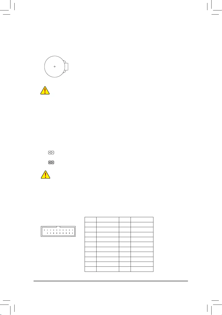
15) BAT (Battery)
Thebatteryprovidespowertokeepthevalues(suchasBIOScongurations,date,andtimeinformation)
in the CMOS when the computer is turned off. Replace the battery when the battery voltage drops to a low
level, or the CMOS values may not be accurate or may be lost.
You may clear the CMOS values by removing the battery:
1. Turn off your computer and unplug the power cord.
2. Gently remove the battery from the battery holder and wait for one minute. (Or use a
metal object like a screwdriver to touch the positive and negative terminals of the battery
holder, making them short for 5 seconds.)
3. Replace the battery.
4. Plug in the power cord and restart your computer.
•Always turn off your computer and unplug the power cord before replacing the battery.
•Replacethebatterywithanequivalentone.Damagetoyourdevicesmayoccurifthebatteryis
replaced with an incorrect model.
•Contact the place of purchase or local dealer if you are not able to replace the battery by yourself
or uncertain about the battery model.
•Wheninstallingthebattery,notetheorientationofthepositiveside(+)andthenegativeside(-)
of the battery (the positive side should face up).
•Used batteries must be handled in accordance with local environmental regulations.
16) CLR_CMOS (Clear CMOS Jumper)
UsethisjumpertocleartheBIOScongurationandresettheCMOSvaluestofactorydefaults.Toclear
the CMOS values, use a metal object like a screwdriver to touch the two pins for a few seconds.
•Always turn off your computer and unplug the power cord from the power outlet before clearing
the CMOS values.
•Aftersystemrestart,gotoBIOSSetuptoloadfactorydefaults(selectLoadOptimizedDefaults)or
manuallyconguretheBIOSsettings(refertoChapter2,«BIOSSetup,»forBIOScongurations).
Open: Normal
Short: Clear CMOS Values
Pin No. Denition Pin No. Denition
1 VBUS 11 D2+
2 SSRX1- 12 D2-
3 SSRX1+ 13 GND
4GND 14 SSTX2+
5 SSTX1- 15 SSTX2-
6 SSTX1+ 16 GND
7GND 17 SSRX2+
8D1- 18 SSRX2-
9D1+ 19 VBUS
10 NC 20 No Pin
17) F_USB30 (USB 3.1 Gen 1 Header)
TheheaderconformstoUSB3.1Gen1andUSB2.0specicationandcanprovidetwoUSBports.For
purchasing the optional 3.5″ front panel that provides two USB 3.1 Gen 1 ports, please contact the local
dealer.
F_USB30 F_U
B_
F_ F_
_
B
BS_
B
SB_
B
_S
S_
_
B
_U
_
B
S
123
123
123
123
1
1
1
1
BSS
S
_S
SSU
1 2 3
S3 BSSS
U
__ 3
F_USB3F
S _
S _
S _
SF
B_
B_
F
_0
S
S
_0F
_F
_
_
__B
U
S _S
_ SF_
USB0_B
B_ F_USB3
F_USB303
_
_3U
10
11
1
20
— 19 —
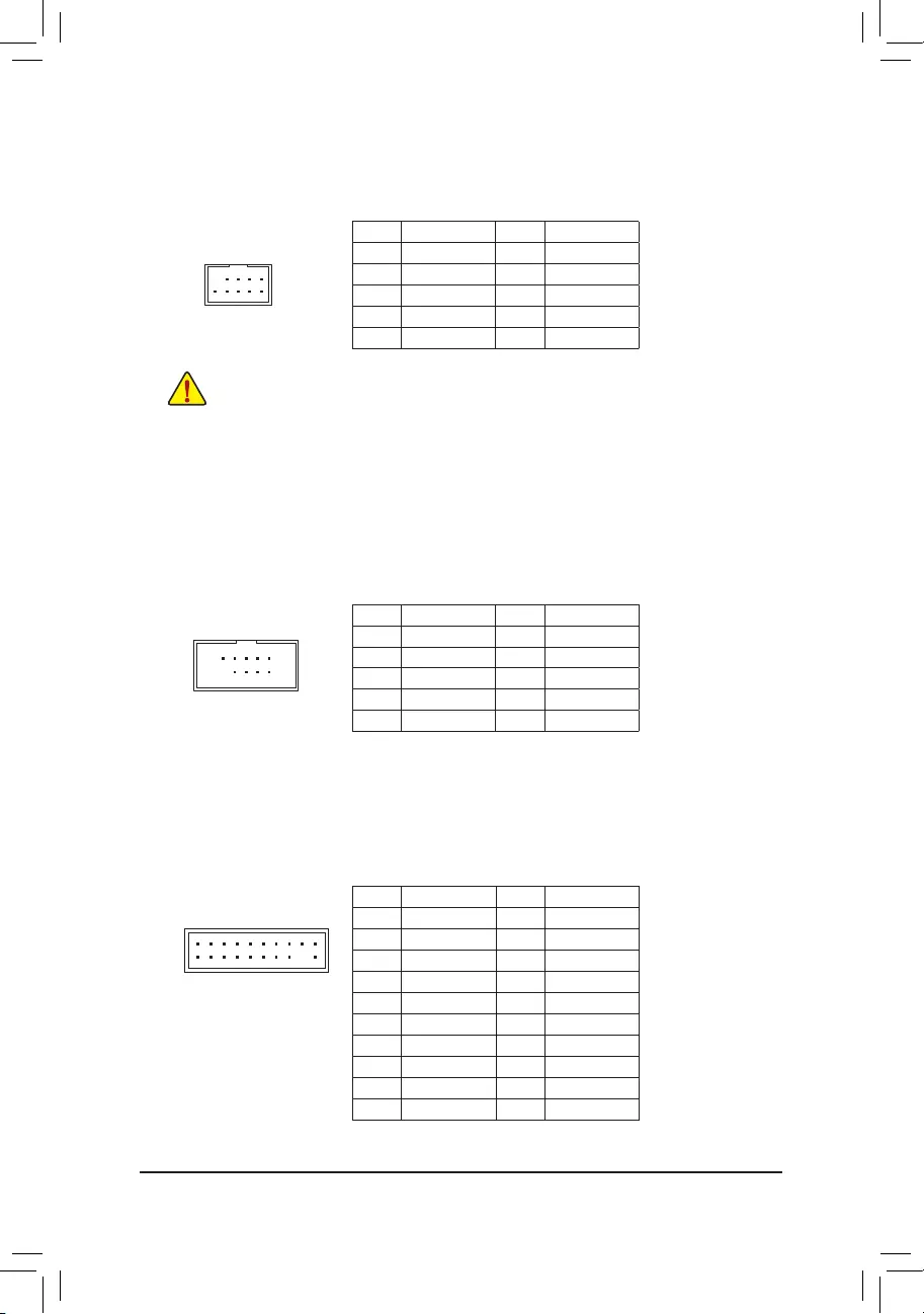
18) F_USB1/F_USB2 (USB 2.0/1.1 Headers)
TheheadersconformtoUSB2.0/1.1specication.EachUSBheadercanprovidetwoUSBportsviaan
optional USB bracket. For purchasing the optional USB bracket, please contact the local dealer.
Pin No. Denition Pin No. Denition
1 Power (5V) 6 USBDY+
2 Power (5V) 7 GND
3USBDX- 8GND
4USBDY— 9 No Pin
5USBDX+ 10 NC
•DonotplugtheIEEE1394bracket(2×5-pin)cableintotheUSB2.0/1.1header.
•Prior to installing the USB bracket, be sure to turn off your computer and unplug the power cord
from the power outlet to prevent damage to the USB bracket.
10
9
2
1
10
9
2
1
19) COMA (Serial Port Header)
The COM header can provide one serial port via an optional COM port cable. For purchasing the optional
COM port cable, please contact the local dealer.
Pin No. Denition Pin No. Denition
1NDCD- 6NDSR-
2 NSIN 7 NRTS-
3 NSOUT 8 NCTS-
4NDTR- 9 NRI-
5GND 10 No Pin
20
19
2
1
F_USB30 F_U
B_
F_ F_
_
B
BS_
B
SB_
B
_S
S_
_
B
_U
_
B
S
123
123
123
123
1
1
1
1
BSS
S
_S
SSU
1 2 3
S3 BSSS
U
__ 3
F_USB3F
S _
S _
S _
SF
B_
B_
F
_0
S
S
_0F
_F
_
_
__B
U
S _S
_ SF_
USB0_B
B_ F_USB3
F_USB303
_
_3U
20) TPM (Trusted Platform Module Header)
You may connect a TPM (Trusted Platform Module) to this header.
Pin No. Denition Pin No. Denition
1 LCLK 11 LAD0
2GND 12 GND
3 LFRAME 13 NC
4 No Pin 14 NC
5 LRESET 15 SB3V
6 NC 16 SERIRQ
7LAD3 17 GND
8LAD2 18 NC
9 VCC3 19 NC
10 LAD1 20 NC
— 20 —
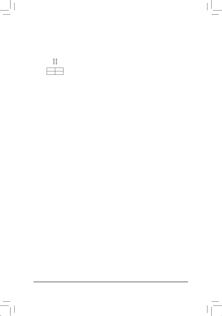
21) CPU/DRAM/VGA/BOOT (Status LEDs)
Thestatus LEDs show whether theCPU, memory, graphics card, andoperating system are working
properlyaftersystempower-on.IftheCPU/DRAM/VGALEDison,thatmeansthecorrespondingdevice
isnotworkingnormally;iftheBOOTLEDison,thatmeansyouhaven’tenteredtheoperatingsystemyet.
CPU: CPUstatusLED
DRAM: MemorystatusLED
VGA: GraphicscardstatusLED
BOOT: OperatingsystemstatusLED
F_USB30 F_U
B_
F_ F_
_
B
BS_
B
SB_
B
_S
S_
_
B
_U
_
B
S
123
123
123
123
1
1
1
1
BSS
S
_S
SSU
1 2 3
S3 BSSS
U
__ 3
F_USB3F
S _
S _
S _
SF
B_
B_
F
_0
S
S
_0F
_F
_
_
__B
U
S _S
_ SF_
USB0_B
B_ F_USB3
F_USB303
_
_3U
CPU DRAM
VGA BOOT
— 21 —
Chapter 2 BIOS Setup
BIOS (Basic Input and Output System) records hardware parameters of the system in the CMOS on the
motherboard. Its major functions include conducting the Power-On Self-Test (POST) during system startup,
saving system parameters and loading operating system, etc. BIOS includes a BIOS Setup program that allows
theusertomodifybasicsystemcongurationsettingsortoactivatecertainsystemfeatures.
Whenthepoweristurnedoff,thebatteryonthemotherboardsuppliesthenecessarypowertotheCMOSto
keepthecongurationvaluesintheCMOS.
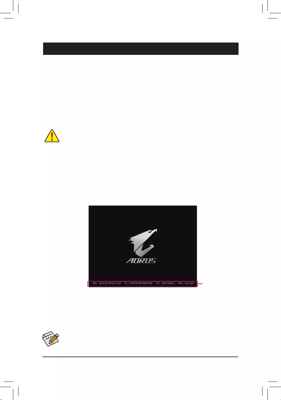
ToaccesstheBIOSSetupprogram,pressthe<Delete>keyduringthePOSTwhenthepoweristurnedon.
ToupgradetheBIOS,useeithertheGIGABYTEQ-Flashor@BIOSutility.
•Q-FlashallowstheusertoquicklyandeasilyupgradeorbackupBIOSwithoutenteringtheoperatingsystem.
•@BIOSisaWindows-basedutilitythatsearchesanddownloadsthelatestversionofBIOSfromtheInternet
and updates the BIOS.
•BecauseBIOSashingispotentiallyrisky,ifyoudonotencounterproblemsusingthecurrentversionofBIOS,
itisrecommendedthatyounotashtheBIOS.ToashtheBIOS,doitwithcaution.InadequateBIOSashing
may result in system malfunction.
•It is recommended that you not alter the default settings (unless you need to) to prevent system instability or other
unexpected results. Inadequately altering the settings may result in system’s failure to boot. If this occurs, try to
cleartheCMOSvaluesandresettheboardtodefaultvalues.(Refertothe»LoadOptimizedDefaults»sectionin
this chapter or introductions of the battery/clear CMOS jumper in Chapter 1 for how to clear the CMOS values.)
2-1 Startup Screen
The following startup Logo screen will appear when the computer boots.
(Sample BIOS Version: E2)
Function Keys
•Whenthesystemisnotstableasusual,selecttheLoad Optimized Defaults item to set your system to its defaults.
•The BIOS Setup menus described in this chapter are for reference only and may differ by BIOS version.
TherearetwodifferentBIOSmodesasfollowsandyoucanusethe<F2>keytoswitchbetweenthetwomodes.
The Classic Setup mode provides detailed BIOS settings. You can press the arrow keys on your keyboard to move
amongtheitemsandpress<Enter>toacceptorenterasub-menu.Oryoucanuseyourmousetoselecttheitemyou
want. Easy Mode allows users to quickly view their current system information or to make adjustments for optimum
performance.InEasyMode,youcanuseyourmousetomovethroughcongurationitems.
— 22 —
2-2 The Main Menu
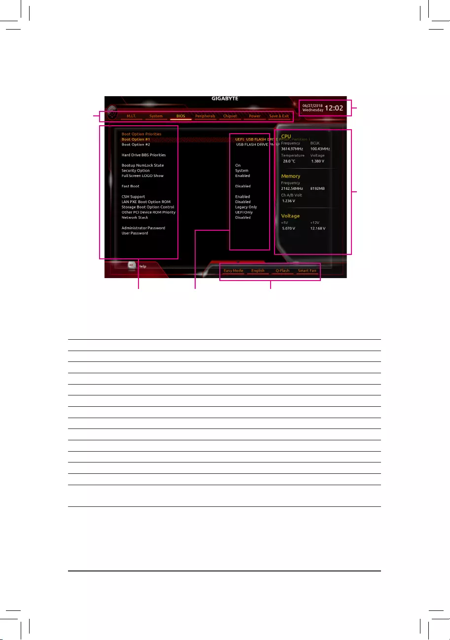
Hardware
Information
CongurationItems Current Settings
Setup Menus
System Time
QuickAccessBarallowsyoutoenterEasyMode,select
BIOSdefaultlanguage,congurefansettings,orenter
Q-Flash.
Classic Setup Function Keys
<f><g>Move the selection bar to select a setup menu
<h><i> Movetheselectionbartoselectancongurationitemonamenu
<Enter> Execute command or enter a menu
<+>/<PageUp> Increase the numeric value or make changes
<—>/<PageDown> Decreasethenumericvalueormakechanges
<F1> Show descriptions of the function keys
<F2> Switch to Easy Mode
<F5> Restore the previous BIOS settings for the current submenus
<F7> LoadtheOptimizedBIOSdefaultsettingsforthecurrentsubmenus
<F8> AccesstheQ-Flashutility
<F9> Displaysysteminformation
<F10> Save all the changes and exit the BIOS Setup program
<F12> Capture the current screen as an image and save it to your USB drive
<Esc> Main Menu: Exit the BIOS Setup program
Submenus: Exit current submenu
— 23 —
2-3 M.I.T.
Whetherthesystemwillworkstablywiththeoverclock/overvoltagesettingsyoumadeisdependentonyouroverall
systemcongurations.Incorrectlydoingoverclock/overvoltagemayresultindamagetoCPU,chipset,ormemory
and reduce the useful life of these components. This page is for advanced users only and we recommend you not to
alter the default settings to prevent system instability or other unexpected results. (Inadequately altering the settings
may result in system’s failure to boot. If this occurs, clear the CMOS values and reset the board to default values.)
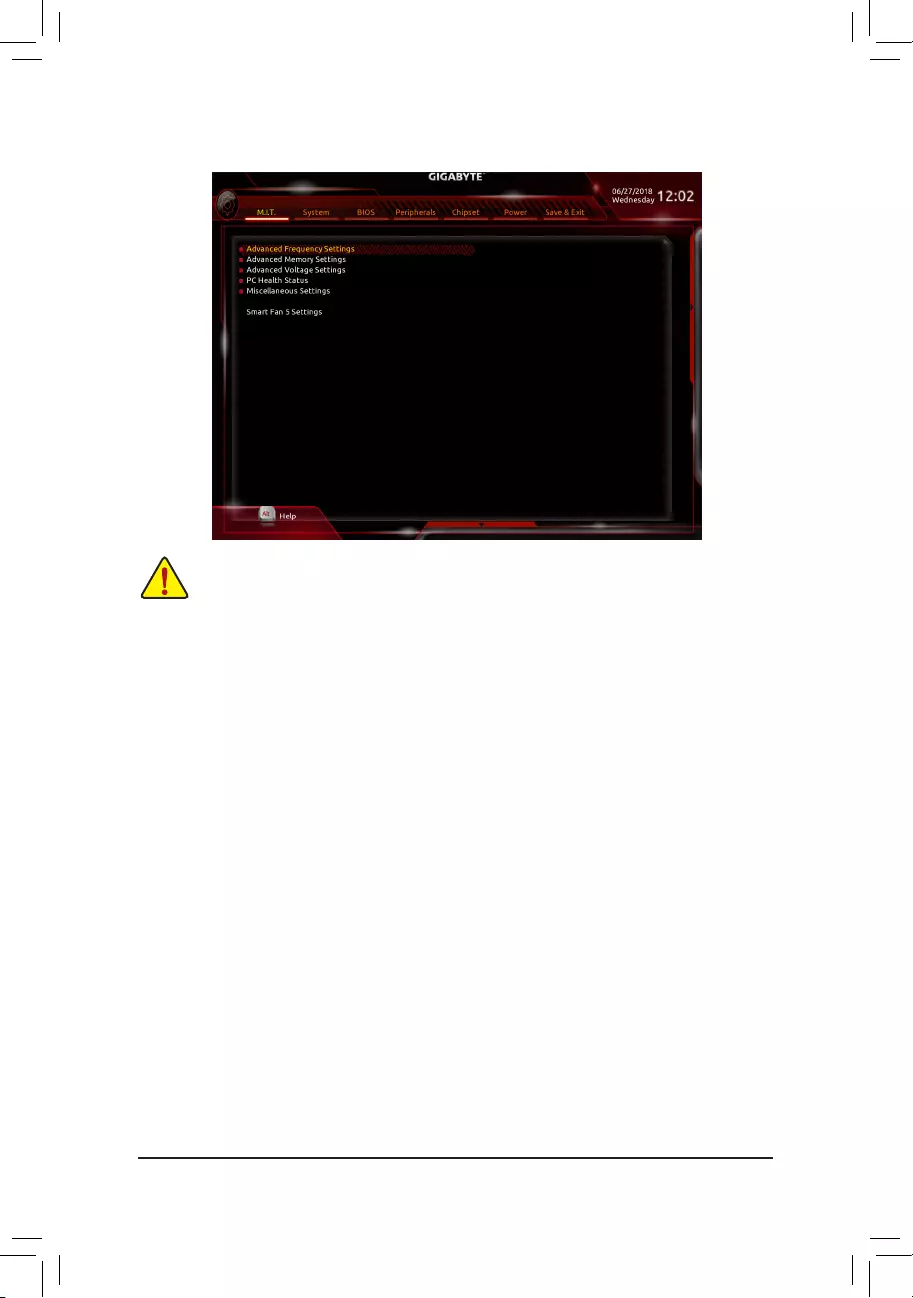
`Advanced Frequency Settings
&Host Clock Value
DisplaysthecurrentoperatingHostClockfrequency.
&GFX Clock Frequency (Note)
Allows you to alter the frequency for the GPU. After you alter the GFX Clock Frequency settings, make
sure to adjust the GFX Core Voltagesettings.(Default:Auto)
Note: The adjustable range is dependent on the CPU being installed. Auto lets the BIOS automatically
congurethissetting.
&GFX Core Voltage (Note)
AllowsyoutoalterthevoltagefortheGPU.(Default:Auto)
Note: The adjustable range is dependent on the CPU being installed. Auto lets the BIOS automatically
congurethissetting.
&CPU Clock Ratio
Allows you to alter the clock ratio for the installed CPU. The adjustable range is dependent on the CPU
being installed.
&CPU Frequency
DisplaysthecurrentoperatingCPUfrequency.
`Advanced CPU Core Settings
&CPU Clock Ratio, CPU Frequency
The settings above are synchronous to those under the same items on the Advanced Frequency Settings
menu.
(Note) This item is present only when you install a CPU that supports this feature.
— 24 —

&Core Performance Boost
Allows you to determine whether to enable the Core Performance Boost (CPB) technology, a CPU
performance-boosttechnology.(Default:Auto)
&AMD Cool&Quiet function
Enabled LetstheAMDCool’n’QuietdriverdynamicallyadjusttheCPUclockandVIDto
reduceheatoutputfromyourcomputeranditspowerconsumption.(Default)
Disabled Disablesthisfunction.
&SVM Mode
VirtualizationenhancedbyVirtualizationTechnologywillallowaplatformtorunmultipleoperatingsystems
andapplicationsinindependentpartitions.Withvirtualization,onecomputersystemcanfunctionasmultiple
virtualsystems.(Default:Disabled)
&Global C-state Control
AllowsyoutodeterminewhethertolettheCPUenterCstates.Whenenabled,theCPUcorefrequency
willbereducedduringsystemhaltstatetodecreasepowerconsumption.(Default:Auto)
&Power Supply Idle Control
Enables or disables Package C6 State.
TypicalCurrentIdle Disablesthisfunction.
Low Current Idle Enables this function.
Auto LetstheBIOSautomaticallycongurethissetting. (Default)
&Opcache Control (Note 1)
Enables or disables Opcache. AutoletstheBIOSautomaticallycongurethissetting.(Default:Auto)
&Downcore Control
Allows you to select the number of CPU cores to enable (the number of CPU cores may vary by CPU).
AutoletstheBIOSautomaticallycongurethissetting.(Default:Auto)
&SMT Mode
Allows you to enable or disable the CPU Simultaneous Multi-Threading technology. This feature only works
for operating systems that support multi-processor mode. AutoletstheBIOSautomaticallycongurethis
setting.(Default:Auto)
&ExtremeMemoryProle(X.M.P.)(Note 2)
AllowstheBIOStoreadtheSPDdataonXMPmemorymodule(s)toenhancememoryperformancewhen
enabled.
Disabled Disablesthisfunction.(Default)
Prole1 UsesProle1settings.
Prole2(Note 2) UsesProle2settings.
&System Memory Multiplier
Allows you to set the system memory multiplier. AutosetsmemorymultiplieraccordingtomemorySPD
data.(Default:Auto)
&Memory Frequency (MHz)
Therstmemoryfrequencyvalueisthenormaloperatingfrequencyofthememorybeingused;thesecond
is the memory frequency that is automatically adjusted according to the System Memory Multiplier settings.
`Advanced Memory Settings
&
ExtremeMemoryProle(X.M.P.)
(Note
2), System Memory Multiplier, Memory Frequency(Mhz)
The settings above are synchronous to those under the same items on the Advanced Frequency Settings
menu.
(Note 1) This item is present only when you install a CPU that supports this feature.
(Note 2) This item is present only when you install a CPU and a memory module that support this feature.
— 25 —

&Memory Timing Mode
Manualallowsthememorytimingsettingsbelowtobecongurable.Optionsare:Auto(default),Manual.
&ProleDDRVoltage
Whenusinganon-XMPmemorymoduleorExtremeMemoryProle(X.M.P.) is set to Disabled, the value
isdisplayedaccordingtoyourmemoryspecication.WhenExtremeMemoryProle(X.M.P.) is set to
Prole1 or Prole2,thevalueisdisplayedaccordingtotheSPDdataontheXMPmemory.
` Standard Timing Control, Advanced Timing Control, CAD Bus Setup Timing, CAD Bus
DriveStrength,DataBusConguration
Thesesectionsprovidememorytimingsettings.Therespectivetimingsettingscreensarecongurable
only when Memory Timing Mode is set to Manual. Note: Your system may become unstable or fail to boot
after you make changes on the memory timings. If this occurs, please reset the board to default values by
loadingoptimizeddefaultsorclearingtheCMOSvalues.
`Advanced Voltage Settings
This sub-menu allows you to set CPU, chipset and memory voltages.
`PC Health Status
&Reset Case Open Status
Disabled Keepsorclearstherecordofpreviouschassisintrusionstatus.(Default)
Enabled Clears the record of previous chassis intrusion status and the Case Openeldwill
show «No» at next boot.
&Case Open
DisplaysthedetectionstatusofthechassisintrusiondetectiondeviceattachedtothemotherboardCI
header.Ifthesystemchassiscoverisremoved,thiseldwillshow«Yes»,otherwiseitwillshow»No».To
clear the chassis intrusion status record, set Reset Case Open Status to Enabled, save the settings to
the CMOS, and then restart your system.
& CPU Vcore/CPU VDDP/DRAM Channel A/B Voltage/+3.3V/+5V/+12V/VCORE SOC
Displaysthecurrentsystemvoltages.
`Miscellaneous Settings
&PCIeSlotConguration
Allows you to set the operation mode of the PCI Express slots to Gen 1, Gen 2, or Gen 3. Actual operation
modeissubjecttothehardwarespecicationofeachslot.AutoletstheBIOSautomaticallycongurethis
setting.(Default:Auto)
&3DMark01 Enhancement
Allowsyoutodeterminewhethertoenhancesomelegacybenchmarkperformance.(Default:Disabled)
`Smart Fan 5 Settings
&Monitor
Allowsyoutoselectatargettomonitorandtomakefurtheradjustment.(Default:CPUFAN)
&Fan Speed Control
Allows you to determine whether to enable the fan speed control function and adjust the fan speed.
Normal Allows the fan to run at different speeds according to the temperature. You can adjust
the fan speed with System Information Viewer based on your system requirements.
(Default)
Silent Allows the fan to run at slow speeds.
Manual Allows you to control the fan speed in the curve graph.
Full Speed Allows the fan to run at full speeds.
— 26 —

&Fan Control Use Temperature Input
Allows you to select the reference temperature for fan speed control.
&Temperature Interval
Allows you to select the temperature interval for fan speed change.
&Fan Control Mode
Auto Lets the BIOS automatically detect the type of fan/pump installed and sets the optimal
controlmode.(Default)
Voltage Voltage mode is recommended for a 3-pin fan.
PWM PWMmodeisrecommendedfora4-pinfan.
&Fan Stop
Enables or disables the fan/pump stop function. You can set the temperature limit using the temperature
curve.Thefanorpumpstopsoperationwhenthetemperatureislowerthanthelimit.(Default:Disabled)
&Temperature
Displaysthecurrenttemperatureoftheselectedtargetarea.
&Fan Speed
Displayscurrentfanspeeds.
&Flow Rate
Displaystheowrateofyourwatercoolingsystem.
&Temperature Warning Control
Setsthewarningthresholdfortemperature.When temperature exceeds the threshold, BIOSwillemit
warningsound.Optionsare:Disabled(default),60oC/140oF, 70oC/158oF, 80oC/176oF, 90oC/194oF.
&Fan Fail Warning
Allows the system to emit warning sound if the fan is not connected or fails. Check the fan condition or fan
connectionwhenthisoccurs.(Default:Disabled)
— 27 —
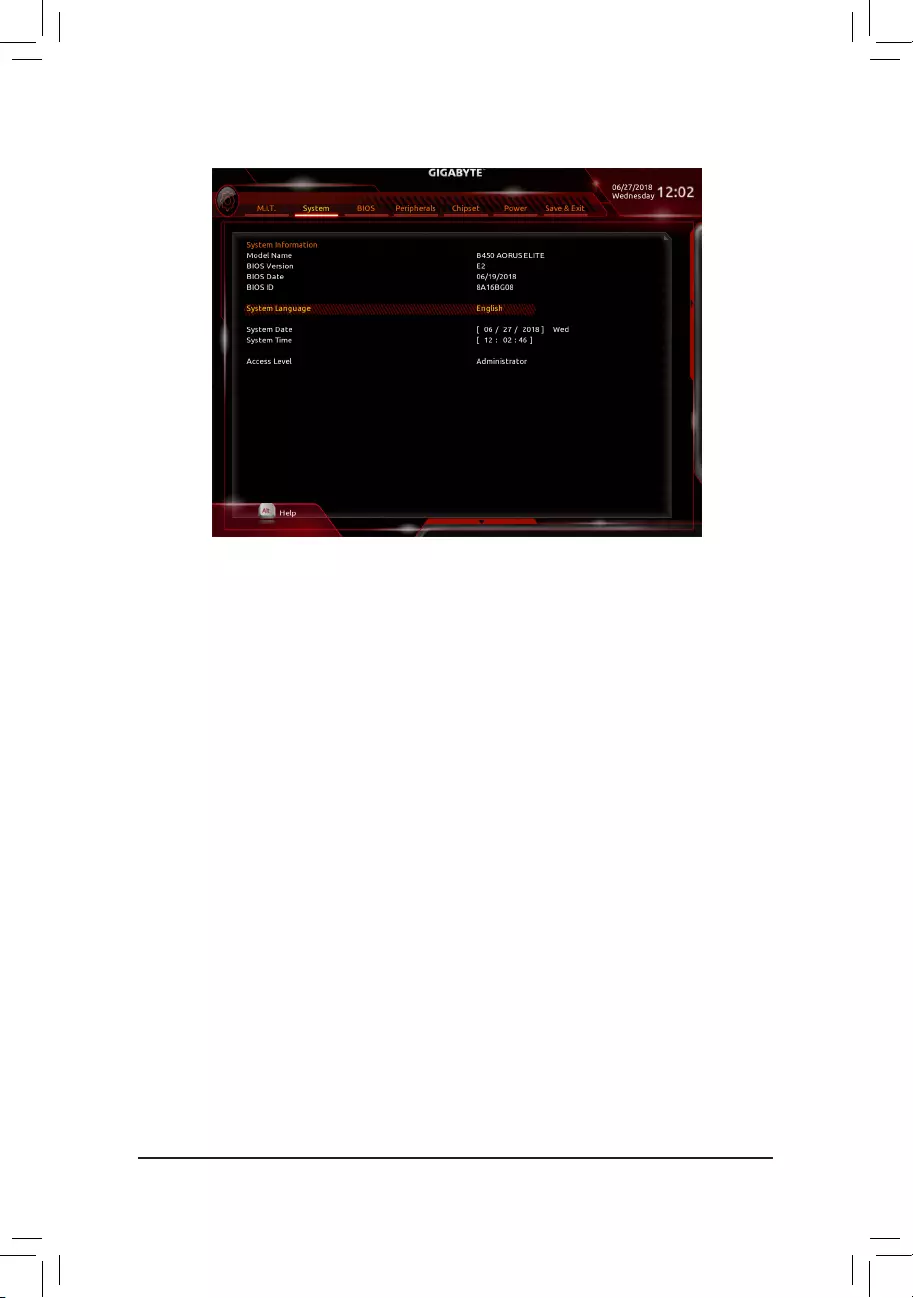
2-4 System
This section provides information on your motherboard model and BIOS version. You can also select the default
language used by the BIOS and manually set the system time.
&System Language
Selects the default language used by the BIOS.
&System Date
Setsthesystemdate.Thedateformatisweek(read-only),month,date,andyear.Use<Enter>toswitch
betweentheMonth,Date,andYeareldsandusethe<PageUp>or<PageDown>keytosetthedesired
value.
&System Time
Sets the system time. The time format is hour, minute, and second. For example, 1 p.m. is 13:00:00. Use
<Enter>toswitchbetweentheHour,Minute,andSecondeldsandusethe<PageUp>or<PageDown>
key to set the desired value.
&Access Level
Displaysthecurrentaccessleveldependingonthetypeofpasswordprotectionused.(Ifnopasswordis
set, the default will display as Administrator.) The Administrator level allows you to make changes to all
BIOS settings; the User level only allows you to make changes to certain BIOS settings but not all.
— 28 —
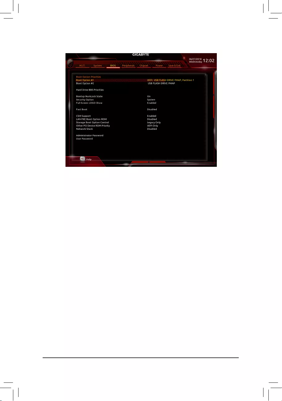
2-5 BIOS
&Boot Option Priorities
Speciestheoverallbootorderfromtheavailabledevices.RemovablestoragedevicesthatsupportGPT
formatwillbeprexedwith«UEFI:»stringonthebootdevicelist.Tobootfromanoperatingsystemthat
supportsGPTpartitioning,selectthedeviceprexedwith»UEFI:»string.
OrifyouwanttoinstallanoperatingsystemthatsupportsGPTpartitioningsuchasWindows1064-bit,
selecttheopticaldrivethatcontainstheWindows1064-bitinstallationdiskandisprexedwith«UEFI:»
string.
&Hard Drive/CD/DVD ROM Drive/Floppy Drive/Network Device BBS Priorities
Speciesthebootorderforaspecicdevicetype,suchasharddrives,opticaldrives,oppydiskdrives,
anddevicesthatsupportBootfromLANfunction,etc.Press<Enter>onthisitemtoenterthesubmenuthat
presents the devices of the same type that are connected. This item is present only if at least one device
for this type is installed.
&Bootup NumLock State
EnablesordisablesNumlockfeatureonthenumerickeypadofthekeyboardafterthePOST.(Default:On)
&Security Option
Specieswhetherapasswordisrequiredeverytimethesystemboots,oronlywhenyouenterBIOSSetup.
Afterconguringthisitem,setthepassword(s)undertheAdministrator Password/User Password item.
Setup A password is only required for entering the BIOS Setup program.
System A password is required for booting the system and for entering the BIOS Setup
program.(Default)
&Full Screen LOGO Show
Allows you to determine whether to display the GIGABYTE Logo at system startup. Disabled skips the
GIGABYTELogowhenthesystemstartsup.(Default:Enabled)
&Fast Boot
Enables or disables Fast Boot to shorten the OS boot process. Ultra Fast provides the fastest bootup
speed.(Default:Disabled)
&SATA Support
AllSataDevices AllSATAdevicesarefunctionalintheoperatingsystemandduringthePOST.
LastBootHDDOnly Exceptforthepreviousbootdrive,allSATAdevicesaredisabledbeforetheOS
bootprocesscompletes.(Default)
ThisitemiscongurableonlywhenFast Boot is set to Enabled or Ultra Fast.
— 29 —

&VGA Support
Allows you to select which type of operating system to boot.
Auto Enables legacy option ROM only.
EFIDriver EnablesEFIoptionROM.(Default)
ThisitemiscongurableonlywhenFast Boot is set to Enabled or Ultra Fast.
&USB Support
Disabled AllUSBdevicesaredisabledbeforetheOSbootprocesscompletes.
Full Initial All USB devices are functional in the operating system and during the POST.
(Default)
Partial Initial Part of the USB devices are disabled before the OS boot process completes.
ThisitemiscongurableonlywhenFast Boot is set to Enabled. This function is disabled when Fast Boot
is set to Ultra Fast.
&PS2 Devices Support
Disabled AllPS/2devicesaredisabledbeforetheOSbootprocesscompletes.
Enabled All PS/2 devices are functional in the operating system and during the POST.
(Default)
ThisitemiscongurableonlywhenFast Boot is set to Enabled. This function is disabled when Fast Boot
is set to Ultra Fast.
&NetWork Stack Driver Support
Disabled Disablesbootingfromthenetwork.(Default)
Enabled Enables booting from the network.
ThisitemiscongurableonlywhenFast Boot is set to Enabled or Ultra Fast.
&CSM Support
Enables or disables UEFI CSM (Compatibility Support Module) to support a legacy PC boot process.
Enabled EnablesUEFICSM.(Default)
Disabled DisablesUEFICSMandsupportsUEFIBIOSbootprocessonly.
&LAN PXE Boot Option ROM
AllowsyoutoselectwhethertoenablethelegacyoptionROMfortheLANcontroller.(Default:Disabled)
ThisitemiscongurableonlywhenCSM Support is set to Enabled.
&Storage Boot Option Control
Allows you to select whether to enable the UEFI or legacy option ROM for the storage device controller.
Disabled DisablesoptionROM.
UEFI Only Enables UEFI option ROM only.
LegacyOnly EnableslegacyoptionROMonly.(Default)
ThisitemiscongurableonlywhenCSM Support is set to Enabled.
&Other PCI Device ROM Priority
Allows you to select whether to enable the UEFI or Legacy option ROM for the PCI device controller other
than the LAN, storage device, and graphics controllers.
Disabled DisablesoptionROM.
UEFIOnly EnablesUEFIoptionROMonly.(Default)
Legacy Only Enables legacy option ROM only.
ThisitemiscongurableonlywhenCSM Support is set to Enabled.
&Network Stack
DisablesorenablesbootingfromthenetworktoinstallaGPTformatOS,suchasinstallingtheOSfrom
theWindowsDeploymentServicesserver.(Default:Disabled)
&Ipv4 PXE Support
EnablesordisablesIPv4PXESupport.ThisitemiscongurableonlywhenNetwork Stack is enabled.
— 30 —

&Ipv4 HTTP Support
EnablesordisablesHTTPbootsupportforIPv4.ThisitemiscongurableonlywhenNetwork Stack is
enabled.
&Ipv6 PXE Support
EnablesordisablesIPv6PXESupport.ThisitemiscongurableonlywhenNetwork Stack is enabled.
&Ipv6 HTTP Support
EnablesordisablesHTTPbootsupportforIPv6.ThisitemiscongurableonlywhenNetwork Stack is
enabled.
&IPSECCerticate
Enablesordisables Internet Protocol Security.This itemis congurable only whenNetwork Stack is
enabled.
&Administrator Password
Allowsyoutocongureanadministratorpassword.Press<Enter>onthisitem,typethepassword,and
thenpress<Enter>.Youwillberequestedtoconrmthepassword.Typethepasswordagainandpress
<Enter>.Youmustentertheadministratorpassword(oruserpassword)atsystemstartupandwhenentering
BIOSSetup.Differingfromtheuserpassword,theadministratorpasswordallowsyoutomakechangesto
all BIOS settings.
&User Password
Allowsyoutocongureauserpassword.Press<Enter>onthisitem,typethepassword,andthenpress
<Enter>.Youwillberequestedtoconrmthepassword.Typethepasswordagainandpress<Enter>.
You must enter the administrator password (or user password) at system startup and when entering BIOS
Setup. However, the user password only allows you to make changes to certain BIOS settings but not all.
Tocancelthepassword,press<Enter>onthepassworditemandwhenrequestedforthepassword,enter
thecorrectonerst.Whenpromptedforanewpassword,press<Enter>withoutenteringanypassword.
Press<Enter>againwhenpromptedtoconrm.
NOTE:BeforesettingtheUserPassword,besuretosettheAdministratorPasswordrst.
— 31 —
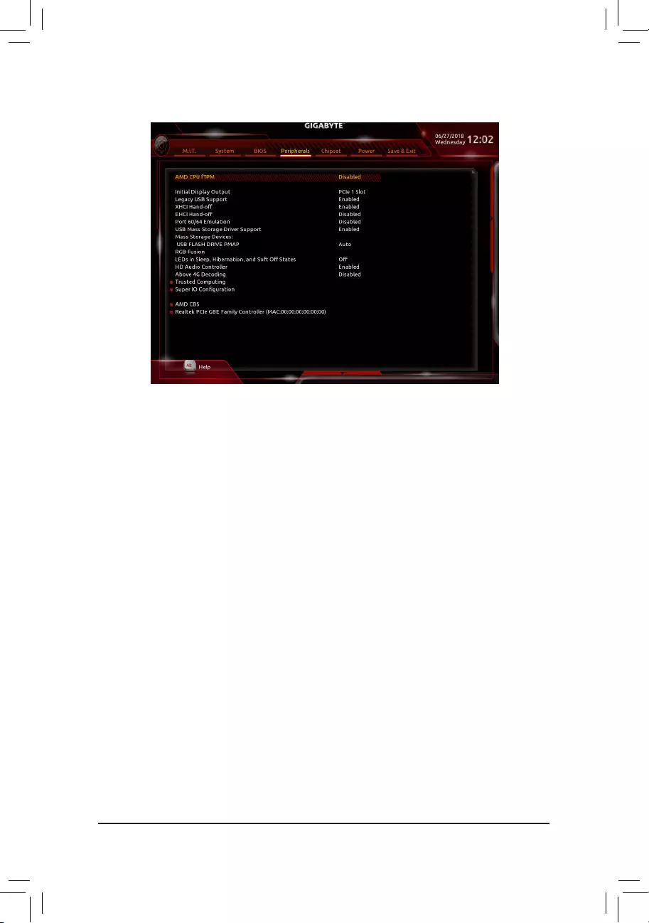
2-6 Peripherals
&AMD CPU fTPM
EnablesordisablestheTPM2.0functionintegratedintheAMDCPU.(Default:Disabled)
&Initial Display Output
SpeciestherstinitiationofthemonitordisplayfromtheinstalledPCIExpressgraphicscardortheonboard
graphics.
IGDVideo(Note) Setstheonboardgraphicsastherstdisplay.
PCIe1Slot SetsthegraphicscardonthePCIEX16slotastherstdisplay.(Default)
PCIe2Slot SetsthegraphicscardonthePCIEX4slotastherstdisplay.
PCIe3Slot SetsthegraphicscardonthePCIEX1_2slotastherstdisplay.
&Legacy USB Support
AllowsUSBkeyboard/mousetobeusedinMS-DOS.(Default:Enabled)
&XHCI Hand-off
Determineswhether toenable XHCIHand-offfeature for an operating system without XHCI Hand-off
support.(Default:Enabled)
&EHCI Hand-off
Determineswhether toenable EHCIHand-offfeature for an operating system without EHCI Hand-off
support.(Default:Disabled)
&Port 60/64 Emulation
Enables or disables emulation of I/O ports 64h and 60h. This should be enabled for full legacy support
forUSBkeyboards/miceinMS-DOSorinoperatingsystemthatdoesnotnativelysupportUSBdevices.
(Default:Disabled)
&USB Mass Storage Driver Support
EnablesordisablessupportforUSBstoragedevices.(Default:Enabled)
&Mass Storage Devices
DisplaysalistofconnectedUSBmassstoragedevices.ThisitemappearsonlywhenaUSBstoragedevice
is installed.
(Note) This item is present only when you install a CPU that supports this feature.
— 32 —

&RGB Fusion
AllowsyoutosettheLEDlightingmodeforthemotherboard.
Off Disablesthisfunction.
PulseMode AllLEDssimultaneouslyfadeinandfadeout.
ColorCycle AllLEDssimultaneouslycyclethroughafullspectrumofcolors.
StaticMode AllLEDsemitasinglecolor.(Default)
FlashMode AllLEDssimultaneouslyashonandoff.
DoubleFlash AllLEDsashinaninterlacedpattern.
&LEDs in Sleep, Hibernation, and Soft Off States
AllowsyoutosetthelightingmodeofthemotherboardLEDsinsystemS3/S4/S5state.
Thisfeatureissupportedonlywitha5VdigitalLEDstrip.
Off DisablestheselectedlightingmodewhenthesystementersS3/S4/S5state.(Default)
On Enables the selected lighting mode when the system enters S3/S4/S5 state.
&HD Audio Controller
Enablesordisablestheonboardaudiofunction.(Default:Enabled)
If you wish to install a 3rd party add-in audio card instead of using the onboard audio, set this item to
Disabled.
&Above 4G Decoding
Enables or disables 64-bit capable devices to be decoded in above 4 GB address space (only if your system
supports 64-bit PCI decoding). Set to Enabled if more than one advanced graphics card are installed and
their drivers are not able to be launched when entering the operating system (because of the limited 4 GB
memoryaddressspace).(Default:Disabled)
`Trusted Computing
Enables or disables Trusted Platform Module (TPM).
`SuperIOConguration
&Serial Port 1
Enablesordisablestheonboardserialport.(Default:Enabled)
`AMD CBS
Thissub-menuprovidesAMDCBS-relatedcongurationoptions.
`Realtek PCIe GBE Family Controller
Thissub-menuprovidesinformationonLANcongurationandrelatedcongurationoptions.
— 33 —
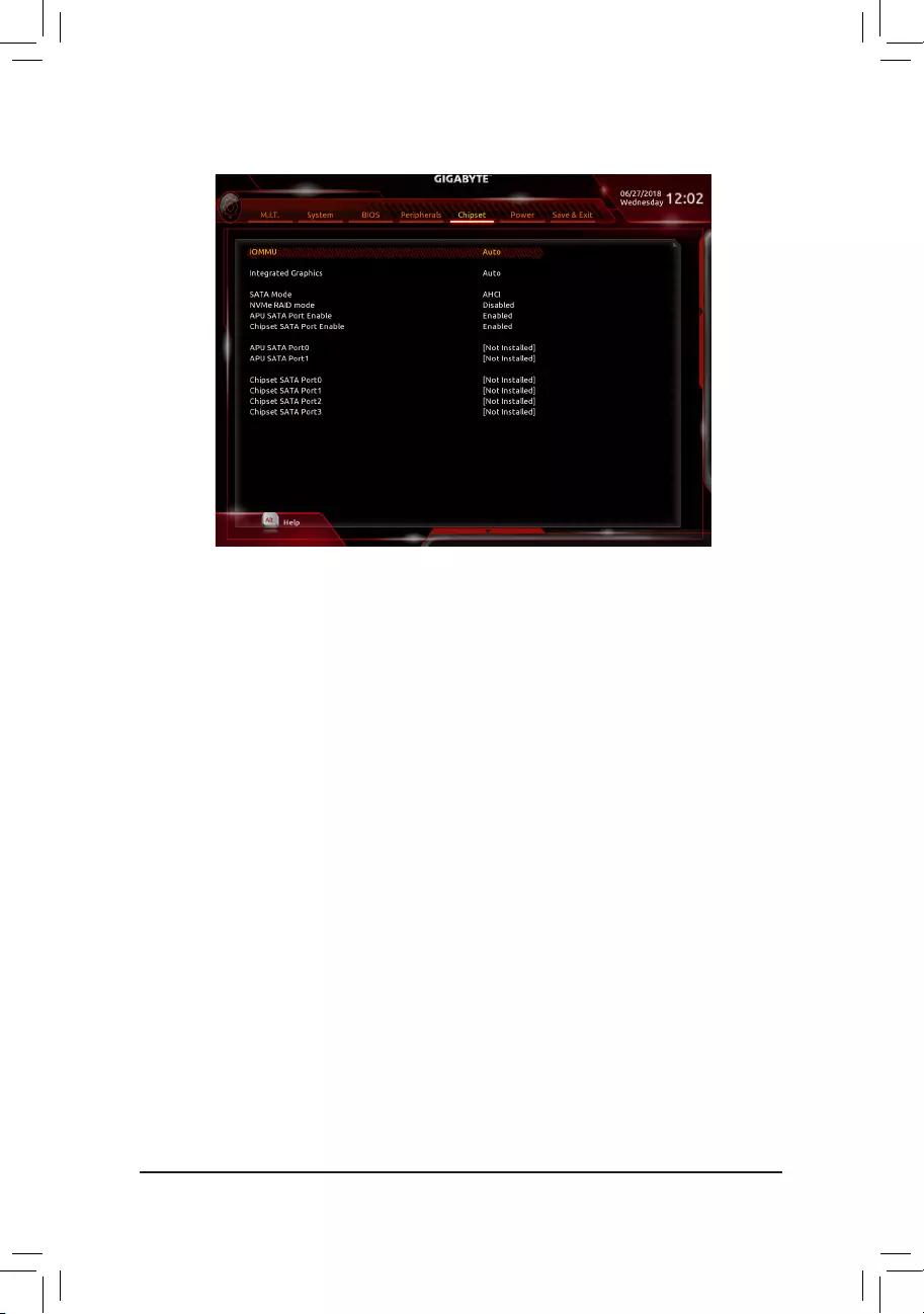
&IOMMU
EnablesordisablesAMDIOMMUsupport.(Default:Auto)
&Integrated Graphics (Note)
Enables or disables the onboard graphics function.
Auto The BIOS will automatically enable or disable the onboard graphics depending on the
graphicscardbeinginstalled.(Default)
Forces Enables the onboard graphics.
Disabled Disablestheonboardgraphics.
&UMA Mode (Note)
Specify the UMA mode.
Auto LetstheBIOSautomaticallycongurethissetting.(Default)
UMASpecied SetstheUMAFrameBufferSize.
UMA Auto Sets the display resolution.
ThisitemiscongurableonlywhenIntegrated Graphics is set to Force.
&UMA Frame Buffer Size (Note)
Framebuffersizeisthetotalamountofsystemmemoryallocatedsolelyfortheonboardgraphicscontroller.
MS-DOS,forexample,willuseonlythismemoryfordisplay.Optionsare:Auto(default),64M~16G.
ThisitemiscongurableonlywhenUMA ModeissettoUMASpecied.
&Display Resolution (Note)
Allows you to set the display resolution. Options are: Auto (default), 1920×1080 and below, 2560×1600,
3840×2160.
ThisitemiscongurableonlywhenUMA ModeissettoUMASpecied.
2-7 Chipset
(Note) This item is present only when you install a CPU that supports this feature.
— 34 —

&SATA Mode
EnablesordisablesRAIDfortheintegratedSATAcontrollersorcongurestheSATAcontrollerstoAHCI
mode.
RAID EnablesRAIDfortheSATAcontroller.
AHCI CongurestheSATAcontrollerstoAHCImode.AdvancedHostControllerInterface
(AHCI)isaninterfacespecicationthatallowsthestoragedrivertoenableadvanced
SerialATAfeaturessuchasNativeCommandQueuingandhotplug.(Default)
&NVMe RAID mode (M2A_SOCKET and M2B_SOCKET Connectors)
AllowsyoutodeterminewhethertouseyourM.2NVMePCIeSSDstocongureRAID.(Default:Disabled)
&APU SATA Port Enable (ASATA3 0, 1 Connectors)
EnablesordisablestheintegratedSATAcontroller(s).(Default:Enabled)
&Chipset SATA Port Enable (SATA3 0, 1, 2, 3 Connectors)
EnablesordisablestheintegratedSATAcontroller(s).(Default:Enabled)
&APU SATA Port 0/1 (ASATA3 0, 1 Connectors)
DisplaystheinformationoftheconnectedSATAdevice(s).
&Chipset SATA Port 0/1/2/3 (SATA3 0, 1, 2, 3 Connectors)
DisplaystheinformationoftheconnectedSATAdevice(s).
— 35 —
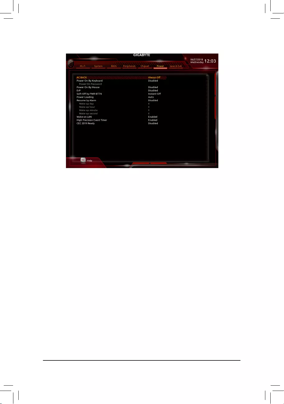
&AC BACK
DeterminesthestateofthesystemafterthereturnofpowerfromanACpowerloss.
Memory The system returns to its last known awake state upon the return of the AC power.
Always On The system is turned on upon the return of the AC power.
AlwaysOff ThesystemstaysoffuponthereturnoftheACpower.(Default)
&Power On By Keyboard
Allows the system to be turned on by a PS/2 keyboard wake-up event.
Note: To use this function, you need an ATX power supply providing at least 1A on the +5VSB lead.
Disabled Disablesthisfunction.(Default)
Password Setapasswordwith1~5characterstoturnonthesystem.
Keyboard98 PressPOWERbuttonontheWindows98keyboardtoturnonthesystem.
Any Key Press any key to turn on the system.
&Power On Password
Set the password when Power On By Keyboard is set to Password.
Press<Enter>onthisitemandsetapasswordwithupto5charactersandthenpress<Enter>toaccept.
Toturnonthesystem,enterthepasswordandpress<Enter>.
Note:Tocancelthepassword,press<Enter>onthisitem.Whenpromptedforthepassword,press<Enter>
again without entering the password to clear the password settings.
&Power On By Mouse
Allows the system to be turned on by a PS/2 mouse wake-up event.
Note: To use this function, you need an ATX power supply providing at least 1A on the +5VSB lead.
Disabled Disablesthisfunction.(Default)
Move Move the mouse to turn on the system.
DoubleClick Doubleclickonleftbuttononthemousetoturnonthesystem.
&ErP
DetermineswhethertoletthesystemconsumeleastpowerinS5(shutdown)state.Note:Whenthisitem
is set to Enabled, the following functions will become unavailable: Resume by Alarm, PME event wake
up, power on by mouse, power on by keyboard, and wake on LAN.
2-8 Power
— 36 —

&Soft-Off by PWR-BTTN
ConguresthewaytoturnoffthecomputerinMS-DOSmodeusingthepowerbutton.
Instant-Off Pressthepowerbuttonandthenthesystemwillbeturnedoffinstantly.(Default)
Delay4Sec. Pressandholdthepowerbuttonfor4secondstoturnoffthesystem.Ifthepower
button is pressed for less than 4 seconds, the system will enter suspend mode.
&Power Loading
Enablesordisablesdummyload.Whenthepowersupplyisatlowload,aself-protectionwillactivatecausing
ittoshutdownorfail.Ifthisoccurs,pleasesettoEnabled.AutoletstheBIOSautomaticallycongurethis
setting.(Default:Auto)
&Resume by Alarm
Determineswhethertopoweronthesystematadesiredtime.(Default:Disabled)
If enabled, set the date and time as following:
Wakeupday:Turnonthesystemataspecictimeoneachdayoronaspecicdayinamonth.
Wakeuphour/minute/second:Setthetimeatwhichthesystemwillbepoweredonautomatically.
Note:Whenusingthisfunction,avoidinadequateshutdownfromtheoperatingsystemorremovalofthe
AC power, or the settings may not be effective.
&Wake on LAN
EnablesordisablesthewakeonLANfunction.(Default:Enabled)
&High Precision Event Timer
EnablesordisablesHighPrecisionEventTimer(HPET)intheoperatingsystem.(Default:Enabled)
&CEC 2019 Ready
Allows you to select whether to allow the system to adjust power consumption when it is in shutdown, idle,
orstandbystateinordertocomplywiththeCEC(CaliforniaEnergyCommission)2019Standards.(Default:
Disabled)
— 37 —
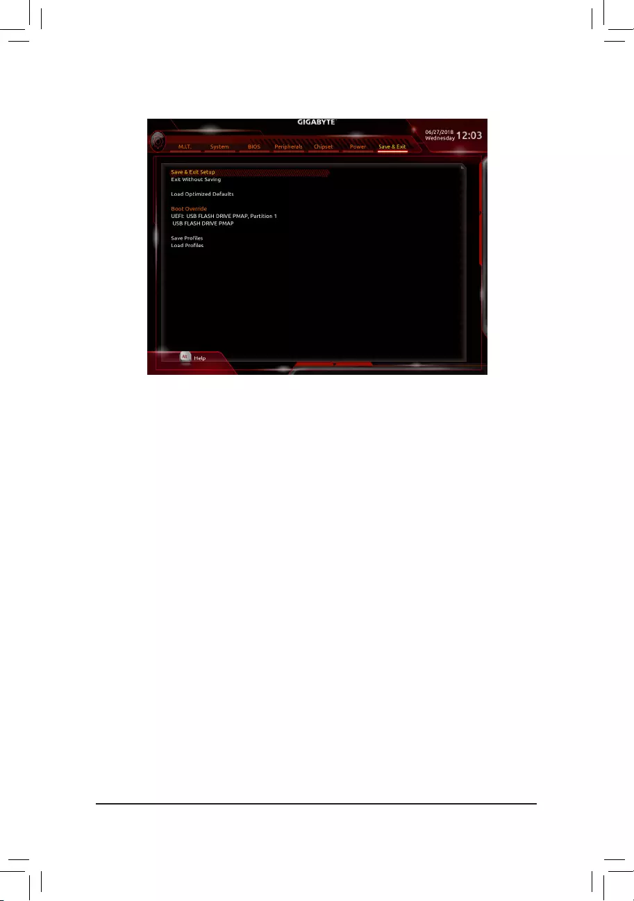
2-9 Save & Exit
&Save & Exit Setup
Press<Enter>onthisitemandselectYes. This saves the changes to the CMOS and exits the BIOS Setup
program. Select Noorpress<Esc>toreturntotheBIOSSetupMainMenu.
&Exit Without Saving
Press<Enter>onthisitemandselectYes. This exits the BIOS Setup without saving the changes made
in BIOS Setup to the CMOS. Select Noorpress<Esc>toreturntotheBIOSSetupMainMenu.
&Load Optimized Defaults
Press<Enter>onthisitemandselectYes to load the optimal BIOS default settings. The BIOS defaults
settingshelpthesystemtooperateinoptimumstate.AlwaysloadtheOptimizeddefaultsafterupdating
the BIOS or after clearing the CMOS values.
&Boot Override
Allowsyoutoselectadevicetobootimmediately.Press<Enter>onthedeviceyouselectandselectYes
toconrm.Yoursystemwillrestartautomaticallyandbootfromthatdevice.
&SaveProles
ThisfunctionallowsyoutosavethecurrentBIOSsettingstoaprole.Youcancreateupto8prolesand
saveasSetupProle1~SetupProle8.Press<Enter>tocomplete.OryoucanselectSelect File in
HDD/FDD/USBtosavetheproletoyourstoragedevice.
&LoadProles
If your system becomes unstable and you have loaded the BIOS default settings, you can use this function
toloadtheBIOSsettingsfromaprolecreatedbefore,withoutthehasslesofreconguringtheBIOS
settings.Firstselecttheproleyouwishtoloadandthenpress<Enter>tocomplete.YoucanselectSelect
File in HDD/FDD/USBtoinputtheprolepreviouslycreatedfromyourstoragedeviceorloadtheprole
automatically created by the BIOS, such as reverting the BIOS settings to the last settings that worked
properly (last known good record).
— 38 —
Chapter 3 Appendix
3-1 ConguringaRAIDSet
Before you begin, please prepare the following items:
•AtleasttwoSATAharddrivesorSSDs(Note 1) (to ensure optimal performance, it is recommended that you
use two hard drives with identical model and capacity). (Note 2)
•Windowssetupdisk.
•Motherboard driver disk.
•A USB thumb drive.
ConguringtheOnboardSATAController
A. Installing SATA hard drive(s) in your computer
Installtheharddrives/SSDsintheSATA/M.2connectorsonthemotherboard.Thenconnectthepowerconnectors
from your power supply to the hard drives.
B.ConguringSATAcontrollermodeinBIOSSetup
MakesuretoconguretheSATAcontrollermodecorrectlyinsystemBIOSSetup.
Steps:
1. Turnonyourcomputerandpress<Delete>toenterBIOSSetupduringthePOST(Power-OnSelf-Test).
Under Chipset, ensure Chipset SATA Port Enable is enabled. Set SATA Mode to RAID. Then save the
settingsandrestartyourcomputer.(IfyouwanttouseNVMePCIeSSDstocongureRAID,makesureto
set NVMe RAID mode to Enabled.)
2. IfyouwanttocongureUEFIRAID,followthestepsin«C-1.»ToenterthelegacyRAIDROM,savethe
settings and exit BIOS Setup. Refer to «C-2» for more information.
The BIOS Setup menus described in this section may differ from the exact settings for your motherboard.
The actual BIOS Setup menu options you will see shall depend on the motherboard you have and
the BIOS version.
C-1.UEFIRAIDConguration
Steps:
1. In BIOS Setup, go to BIOS and set CSM Support to Disabled. Save the changes and exit BIOS Setup.
2. After the system reboot, enter BIOS Setup again. Then enter the Peripherals\RAIDXpert2Conguration
Utility sub-menu.
3. On the RAIDXpert2CongurationUtilityscreen,press<Enter>on Array Management to enter the Create
Array screen. Then, select a RAID level.RAIDlevelssupportedincludeRAID0(Stripe),RAID1(Mirror),
andRAID10(theselectionsavailabledependonthenumberoftheharddrivesbeinginstalled).Next,press
<Enter>onSelect Physical Disks to enter the Select Physical Disks screen.
4. On the Select Physical Disksscreen,selecttheharddrivestobeincludedintheRAIDarrayandsetthem
to Enabled. Next, use the down arrow key to move to Apply Changesandpress<Enter>.Thenreturnto
thepreviousscreenandsettheArraySize,ArraySizeUnit,ReadCachePolicyandWriteCachePolicy.
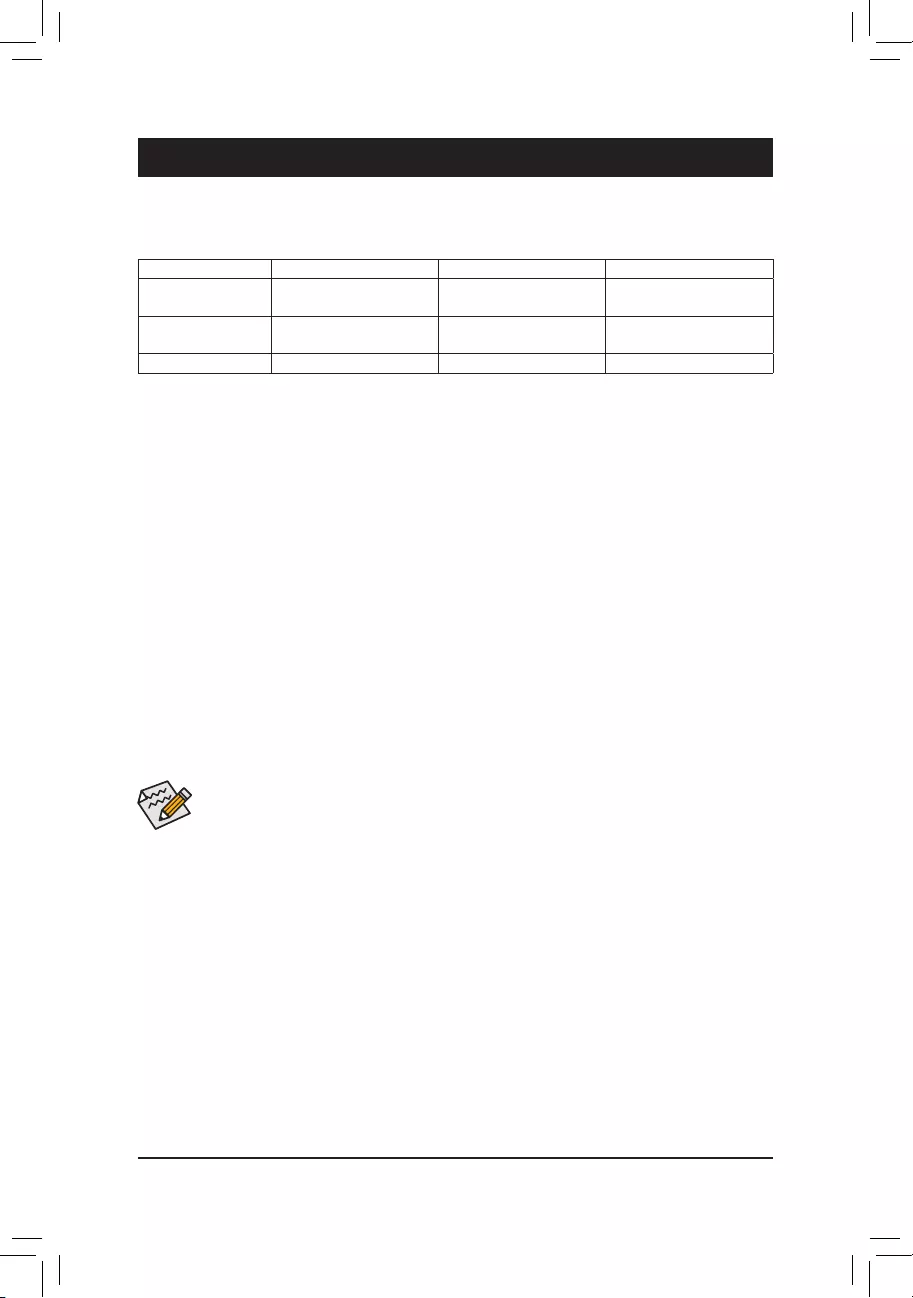
RAID Levels
RAID 0 RAID 1 RAID 10
Minimum Number of
HardDrives ≥2 2 4
Array Capacity Number of hard drives *
Sizeofthesmallestdrive
Sizeofthesmallestdrive (Number of hard drives/2) *
Sizeofthesmallestdrive
Fault Tolerance No Yes Yes
(Note1) AnM.2PCIeSSDcannotbeusedtosetupaRAIDseteitherwithanM.2SATASSDoraSATAharddrive.
(Note 2) Refer to «1-7 Internal Connectors,» for the installation notices for the M.2 and SATA connectors.
— 39 —
PleasevisitGIGABYTE’swebsitefordetailsonconguringaRAIDarray.
C-2.ConguringLegacyRAIDROM
EnterthelegacyRAIDBIOSsetuputilitytocongureaRAIDarray.Skipthisstepandproceedwiththeinstallation
ofWindowsoperatingsystemforanon-RAIDconguration.
Steps:
1. In BIOS Setup, go to BIOS and set CSM Support to Enabled. Save the changes and exit BIOS Setup. After
the POST memory test begins and before the operating system boot begins, look for a message which says
«Press<Ctrl-R>toCongure».Press<Ctrl>+<R>toentertheRAIDBIOSsetuputility.
2. Tocreateanewarray,press<Enter>ontheCreateArrayoption.
3. TheselectionbarwillmovetotheDiskssectionontherightofthescreen.Selecttheharddrivestobeincluded
intheRAIDarray.Usetheupordownarrowkeytoselectaharddriveandpress<Insert>.Theselectedhard
drivewillbeshowningreen.Tousealloftheharddrives,simplypress<A>toselectall.Thenpress<Enter>
and the selection bar will move to the User Input section on the left bottom of the screen.
4. First,selectaRAIDmodeandpress<Enter>.Theselectionsavailabledependonthenumberoftheharddrives
beinginstalled.Thenfollowtheon-screeninstructionstospecifythearraysize.YoucanselectAllavailable
spacetousethemaximumsizeallowedorusetheupordownarrowkeytoadjustthesizeandpress<Enter>.
5. Selectacachingmode.OptionsincludeRead/Write,ReadOnly,andNone.Thenpress<Enter>toproceed.
6. Finally,amessagewhichsays«ConrmCreationofArray»willappear.Press<C>toconrmor<Esc>to
return to the previous screen.
7. Whencompleted,youwillseethenewarrayonthemainscreen.ToexittheRAIDBIOSutility,press<Esc>
andthenpress<C>toconrm.
Installing the RAID/AHCI Driver and Operating System
WiththecorrectBIOSsettings,youarereadytoinstalltheoperatingsystem.
Installing the Operating System
AssomeoperatingsystemsalreadyincludeRAID/AHCIdriver,youdonotneedtoinstallseparateRAID/AHCI
driverduringtheWindowsinstallationprocess.Aftertheoperatingsystemisinstalled,werecommendthatyou
install all required drivers from the motherboard driver disk using «Xpress Install» to ensure system performance
andcompatibility.IftheoperatingsystemtobeinstalledrequiresthatyouprovideadditionalRAID/AHCIdriver
during the OS installation process, please refer to the steps below:
1. Copy the Hw10 folder under the \Boot folder in the driver disk to your USB thumb drive.
2. BootfromtheWindowssetupdiskandperformstandardOSinstallationsteps.Whenthescreenrequesting
you to load the driver appears, select Browse.
3. Insert the USB thumb drive and then browse to the location of the driver. The location of the drivers is as
follows:
\Hw10\RAID\x64
4. Select AMD-RAID Bottom DevicerstandclickNexttoloadthedriver.ThenselectAMD-RAID Controller
and click Next to load the driver. Finally, continue the OS installation.
5. After setting the capacity, move to Create Arrayandpress<Enter>tobegin.
6. After completing, you’ll be brought back to the Array Management screen. Under Manage Array Properties
youcanseethenewRAIDvolumeandinformationonRAIDlevel,arrayname,arraycapacity,etc.
— 40 —
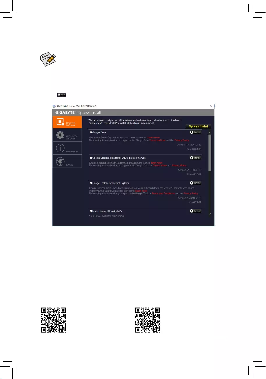
• Beforeinstallingthedrivers,rstinstalltheoperatingsystem.
• After installing the operating system, insert the motherboard driver disk into your optical drive. Click
on the message «Tap to choose what happens with this disc» on the top-right corner of the screen
and select «Run Run.exe.» (Or go to My Computer, double-click the optical drive and execute the
Run.exe program.)
3-2 Drivers Installation
«Xpress Install» will automatically scan your system and then list all of the drivers that are recommended to
install. You can click the Xpress Install button and «Xpress Install» will install all of the selected drivers. Or click
the arrow icon to individually install the drivers you need.
Please visit GIGABYTE’s website for
more software information.
Please visit GIGABYTE’s website for
more troubleshooting information.
— 41 —
Regulatory Statements
Regulatory Notices
This document must not be copied without our written permission, and the contents there of must not be imparted to a
thirdpartynorbeusedforanyunauthorizedpurpose.
Contraventionwillbeprosecuted.Webelievethattheinformationcontainedhereinwasaccurateinallrespectsatthe
time of printing. GIGABYTE cannot, however, assume any responsibility for errors or omissions in this text. Also note
that the information in this document is subject to change without notice and should not be construed as a commitment
by GIGABYTE.
Our Commitment to Preserving the Environment
Inadditiontohigh-efciencyperformance,allGIGABYTEmotherboardsfulllEuropeanUnionregulationsforRoHS
(RestrictionofCertainHazardousSubstancesinElectricalandElectronicEquipment)andWEEE(WasteElectricaland
Electronic Equipment) environmental directives, as well as most major worldwide safety requirements. To prevent releases
ofharmfulsubstancesintotheenvironmentandtomaximizetheuseofournaturalresources,GIGABYTEprovidesthe
following information on how you can responsibly recycle or reuse most of the materials in your «end of life» product.
Restriction of Hazardous Substances (RoHS) Directive Statement
GIGABYTEproductshavenotintendedtoaddandsafefromhazardoussubstances(Cd,Pb,Hg,Cr+6,PBDEand
PBB). The parts and components have been carefully selected to meet RoHS requirement. Moreover, we at GIGABYTE
are continuing our efforts to develop products that do not use internationally banned toxic chemicals.
Waste Electrical & Electronic Equipment (WEEE) Directive Statement
GIGABYTEwillfulllthenationallawsasinterpretedfromthe2002/96/ECWEEE(WasteElectricalandElectronic
Equipment)directive.TheWEEEDirectivespeciesthetreatment,collection,recyclinganddisposalofelectricand
electronicdevicesandtheircomponents.UndertheDirective,usedequipmentmustbemarked,collectedseparately,
and disposed of properly.
WEEE Symbol Statement
The symbol shown below is on the product or on its packaging, which indicates that this product must
not be disposed of with other waste. Instead, the device should be taken to the waste collection centers
for activation of the treatment, collection, recycling and disposal procedure. The separate collection and
recycling of your waste equipment at the time of disposal will help to conserve natural resources and ensure
that it is recycled in a manner that protects human health and the environment. For more information about where you
candropoffyourwasteequipmentforrecycling,pleasecontactyourlocalgovernmentofce,yourhouseholdwaste
disposal service or where you purchased the product for details of environmentally safe recycling.
Whenyourelectricalorelectronicequipmentisnolongerusefultoyou,«takeitback»toyourlocalorregionalwaste
collection administration for recycling.
If you need further assistance in recycling, reusing in your «end of life» product, you may contact us at the Customer
Care number listed in your product’s user’s manual and we will be glad to help you with your effort.
Finally, we suggest that you practice other environmentally friendly actions by understanding and using the energy-saving
features of this product (where applicable), recycling the inner and outer packaging (including shipping containers) this
productwasdeliveredin,andbydisposingoforrecyclingusedbatteriesproperly.Withyourhelp,wecanreducethe
amountofnaturalresourcesneededtoproduceelectricalandelectronicequipment,minimizetheuseoflandllsfor
thedisposalof«endoflife»products,andgenerallyimproveourqualityoflifebyensuringthatpotentiallyhazardous
substances are not released into the environment and are disposed of properly.
Battery Information
EuropeanUnion—Disposalandrecyclinginformation
GIGABYTE Recycling Program (available in some regions)
This symbol indicates that this product and/or battery should not be disposed of with household waste. You must use
the public collection system to return, recycle, or treat them in compliance with the local regulations.
— 42 —

FCC Notice (U.S.A. Only)
This equipment has been tested and found to comply with the limits for a Class B digital device, pursuant to Part
15 of the FCC Rules. These limits are designed to provide reasonable protection against harmful interference
in a residential installation. This equipment generates, uses, and can radiate radio frequency energy and, if not
installed and used in accordance with the instructions, may cause harmful interference to radio communications.
However, there is no guarantee that interference will not occur in a particular installation. If this equipment does
cause harmful interference to radio or television reception, which can be determined by turning the equipment
off and on, the user is encouraged to try to correct the interference by one or more of the following measures:
Reorient or relocate the receiving antenna.
Increase the separation between the equipment and receiver.
Connect the equipment into an outlet on a circuit different from that to which the receiver is connected.
Consult a dealer or experienced TV/radio technician for help.
Canada, Industry Canada (IC) Notices / Canada, avis d’Industry Canada (IC)
This Class B digital apparatus complies with Canadian ICES-003 and RSS-210.
Operation is subject to the following two conditions: (1) this device may not cause interference, and (2) this
device must accept any interference, including interference that may cause undesired operation of the device.
Cet appareil numérique de classe B est conforme aux normes canadiennes ICES-003 et RSS-210.
Son fonctionnement est soumis aux deux conditions suivantes : (1) cet appareil ne doit pas causer
d’interférence et (2) cet appareil doit accepter toute interférence, notamment les interférences qui peuvent
affecter son fonctionnement.
— 43 —
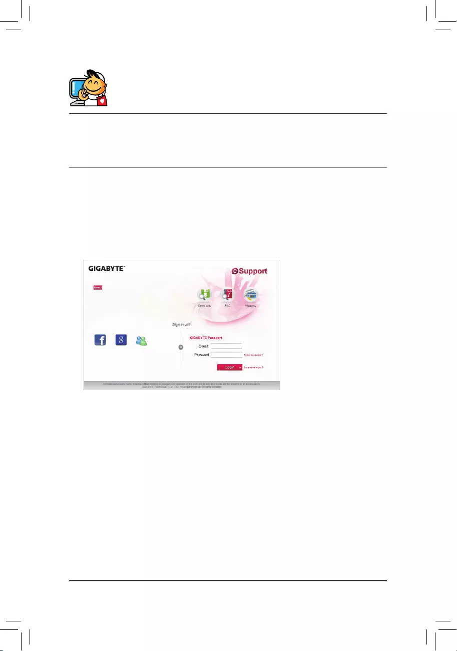
Contact Us
GIGA-BYTE TECHNOLOGY CO., LTD.
Address:No.6,BaoqiangRd.,XindianDist.,NewTaipeiCity231,Taiwan
TEL: +886-2-8912-4000, FAX: +886-2-8912-4005
Tech. and Non-Tech. Support (Sales/Marketing) : https://esupport.gigabyte.com
WEBaddress(English):https://www.gigabyte.com
WEBaddress(Chinese):https://www.gigabyte.com/tw
•GIGABYTE eSupport
To submit a technical or non-technical (Sales/Marketing) question, please link to:
https://esupport.gigabyte.com
— 44 —
Free Manuals for Gigabyte B450 AORUS ELITE (rev. 1.x)
Manufacturer:Gigabyte
Category:Computers & Peripherals
Device:Gigabyte B450 AORUS ELITE (rev. 1.x)
Name:Quick Installation Guide
Language:Português
Pages:9
Size:6.73 MB
Manufacturer:Gigabyte
Category:Computers & Peripherals
Device:Gigabyte B450 AORUS ELITE (rev. 1.x)
Name:Multilingual Installation Guide
Language:العربيةБългарскиČeštinaDeutschΕλληνικάEnglishEspañolفارسىFrançaisעבריתHrvatskiMagyarBahasa IndonesiaItaliano日本語한국어PolskiPortuguêsRomânăРусскийSrpskiไทยTürkçeTiếng Việt中文
Version:103
Pages:2
Size:9.03 MB
DescriptionGigabyte B450 AORUS ELITE (rev. 1.x) Multilingual Installation GuideView Gigabyte B450 AORUS ELITE (rev. 1.x) Multilingual Installation Guide 103 (العربية, Български, Čeština, Deutsch, Ελληνικά, English, Español, فارسى, Français, עברית, Hrvatski, Magyar, Bahasa Indonesia, Italiano, 日本語, 한국어, Polski, Português, Română, Русский, Srpski, ไทย, Türkçe, Tiếng Việt, 中文)
Manufacturer:Gigabyte
Category:Computers & Peripherals
Device:Gigabyte B450 AORUS ELITE (rev. 1.x)
Name:RAID Setup Guide
Language:English
Pages:13
Size:3.07 MB
Manufacturer:Gigabyte
Category:Computers & Peripherals
Device:Gigabyte B450 AORUS ELITE (rev. 1.x)
Name:Unique Features Introduction
Language:English
Pages:27
Size:4.00 MB
Manufacturer:Gigabyte
Category:Computers & Peripherals
Device:Gigabyte B450 AORUS ELITE (rev. 1.x)
Name:Manual
Language:中文中文(简体)
Version:1101
Pages:48
Size:11.82 MB
Manufacturer:Gigabyte
Category:Computers & Peripherals
Device:Gigabyte B450 AORUS ELITE (rev. 1.x)
Name:Manual
Language:한국어
Version:1101
Pages:44
Size:12.88 MB
Manufacturer:Gigabyte
Category:Computers & Peripherals
Device:Gigabyte B450 AORUS ELITE (rev. 1.x)
Name:Manual
Language:日本語
Version:1101
Pages:44
Size:12.94 MB
Manufacturer:Gigabyte
Category:Computers & Peripherals
Device:Gigabyte B450 AORUS ELITE (rev. 1.x)
Name:Manual
Language:Français
Version:1101
Pages:44
Size:12.63 MB
Manufacturer:Gigabyte
Category:Computers & Peripherals
Device:Gigabyte B450 AORUS ELITE (rev. 1.x)
Name:Manual
Language:中文中文(繁體)
Version:1101
Pages:48
Size:13.41 MB
Manufacturer:Gigabyte
Category:Computers & Peripherals
Device:Gigabyte B450 AORUS ELITE (rev. 1.x)
Name:Manual
Language:English
Version:1101
Pages:44
Size:12.72 MB
Gigabyte B450 Aorus Elite
To reduce the impacts on global warming, the packaging materials of this product
are recyclable and reusable. GIGABYTE works with you to protect the environment.
For more product details, please visit GIGABYTE’s website.
User’s Manual
Rev. 1101
12ME-B45ARSE-1101R
Инструкция
Посмотреть инструкция для Gigabyte B450 Aorus Elite бесплатно. Руководство относится к категории материнские платы, 29 человек(а) дали ему среднюю оценку 8.9. Руководство доступно на следующих языках: английский. У вас есть вопрос о Gigabyte B450 Aorus Elite или вам нужна помощь?
Задайте свой вопрос здесь
Изображения продукта (7)

Технические характеристики Gigabyte B450 Aorus Elite
Ниже вы найдете технические характеристики изделия и руководства по эксплуатации Gigabyte B450 Aorus Elite.
Материнская плата Gigabyte B450 Aorus Elite – компонент для ПК с семейством чипсетов AMD и конкретно чипсетом AMD B450. Она совместима с процессорами AMD Athlon, AMD Ryzen 3, AMD Ryzen 3 2-го поколения, AMD Ryzen 3 3-го поколения, AMD Ryzen 5, AMD Ryzen 5 2-го поколения, AMD Ryzen 5 3-го поколения, AMD Ryzen 7, AMD Ryzen 7 2-го поколения и AMD Ryzen 7 3-го поколения, а также AMD Ryzen 9 3-го поколения. Тип слотов оперативной памяти – DIMM, количество слотов – 4. Она может работать с ECC и Non-ECC оперативной памятью. Поддерживаемые частоты тактования памяти – 2133, 2400, 2667 и 2933 МГц. Без буферизации тоже работает. Максимальный объем встроенной памяти – 64 ГБ. Поддерживает HDCP.
Также стоит отметить, что материнская плата выполнена из качественных материалов, что гарантирует ей надежность и долговечность в использовании.
Семейство чипсета материнской платы
AMD
Производитель процессора
AMD
Технология Intel HD Audio
Да
Главная
| Бренд | Gigabyte |
| Модель | B450 Aorus Elite | B450 AORUS ELITE |
| Изделие | материнская плата |
| EAN | 4719331803995, 0889523014653 |
| Язык | английский |
| Тип файла | Руководство пользователя (PDF), Инструкция по установке (PDF) |
Свойства
| Семейство чипсета материнской платы | AMD |
| Чипсет материнской платы | AMD B450 |
| Комплектующие для | ПК |
| Выходные звуковые каналы | 7.1 канала |
| Аудио чип | Realtek ALC892 |
| Поддерживаемые операционные системы Windows | Windows 10, Windows 7 |
| Формат материнской платы | ATX |
| Сертификация | CE, FCC |
Процессор
| Производитель процессора | AMD |
| Совместимые серии процессоров | AMD Athlon, AMD Ryzen 3, AMD Ryzen 3 2nd Gen, AMD Ryzen 3 3rd Gen, AMD Ryzen 5, AMD Ryzen 5 2nd Gen, AMD Ryzen 5 3rd Gen, AMD Ryzen 7, AMD Ryzen 7 2nd Gen, AMD Ryzen 7 3rd Gen, AMD Ryzen 9 3rd Gen |
| Сокет процессора | Разъем AM4 |
Память
| Тип слотов памяти | DIMM |
| Количество слотов памяти | 4 |
| Каналы памяти | Dual-channel |
| Поддерживаемые частоты памяти | 2133,2400,2667,2933 MHz |
| Небуферизованная память | Да |
| Поддерживаемые типы памяти | DDR4-SDRAM |
| Максимальная внутренняя память | 64 GB |
| 2933 MHz |
Графический адаптер
| HDCP | Да |
| Максимальное разрешение | 4096 x 2160 пикселей |
| Поддержка технологии параллельной обработки | CrossFire |
Внутренние порты
| Разъем выхода S/PDIF | Да |
| Количество разъемов SATA III | 6 |
| Количество разъемов SATA II | 0 |
| Разъем питания ATX (24-конт.) | Да |
| 12В разъем питания | Да |
| Разъем вентилятора центрального процессора | Да |
| Количество разъемов вентилятора корпуса | 3 |
| RGB LED контактный разъем | Да |
| Разъем передней панели | Да |
| Аудиоразъем передней панели | Да |
| Количество параллельных разъемов ATA (PATA) | 0 |
| Разъемы USB 2.0 | 2 |
| Разъемы USB 3.2 Gen 1 (3.1 Gen 1) | 1 |
| Разъемы USB 3.2 Gen 2 (3.1 Gen 2) | 0 |
| TPM коннектор | Да |
| Коннекторы последовательного порта | 1 |
Особые свойства процессора
| Технология Intel HD Audio | Да |
| экстремальный профиль памяти Intel | Да |
Сеть
| Подключение Ethernet | Да |
| Тип Ethernet интерфейса | Гигабитный Ethernet |
| Wi-Fi | Нет |
Слоты расширения
| Количество M.2 (M) слотов | 2 |
| PCI Express x16 слоты | 2 |
| PCI Express x1 слоты | 2 |
BIOS
| Перемычка Clear CMOS | Да |
| Тип BIOS | UEFI AMI |
| Размер памяти BIOS | 128 Mbit |
| Версия ACPI | 5.0 |
| Plug & Play | Да |
| Desktop Management Interface (DMI) версия | 2.7 |
| Версия BIOS (SMBIOS) | 2.7 |
Порты на задней панели
| Количество портов USB 2.0 | 4 |
| Количество портов USB 3.2 Gen 1 (3.1 Gen 1) Type-A | 4 |
| Количество портов USB 3.2 Gen 1 (3.1 Gen 1) Type-С | 0 |
| Количество портов USB 3.2 Gen 2 (3.1 Gen 2) Type-A | 0 |
| Количество портов USB 3.2 Gen 2 (3.1 Gen 2) Type-С | 0 |
| Количество портов Ethernet LAN ( RJ-45) | 1 |
| Количество портов eSATA | 0 |
| Количество портов PS/2 | 1 |
| Порты FireWire | 0 |
| Количество портов VGA (D-Sub) | 0 |
| Количество HDMI портов | 1 |
| Количество портов DVI-D | 1 |
| Линейные выходы наушников | 6 |
Вес и размеры
| Ширина | 305 mm |
| Глубина | 235 mm |
| Высота | 80 mm |
Контроллеры хранения данных
| Поддерживаемые типы накопителей | Твердотельный накопитель (SSD) |
| Уровни RAID | 0, 1,10 |
| Поддерживаемые интерфейсы носителя | M.2, SATA |
Логистические данные
| Код гармонизированной системы описания (HS) | 84733020 |
Прочие свойства
показать больше
Часто задаваемые вопросы
Не можете найти ответ на свой вопрос в руководстве? Вы можете найти ответ на свой вопрос ниже, в разделе часто задаваемых вопросов о Gigabyte B450 Aorus Elite.
Как я могу правильно подключить передние панельные разъемы к материнской плате {Gigabyte B450 Aorus Elite}?
Ссылайтесь на схему распиновки в руководстве пользователя материнской платы Gigabyte B450 Aorus Elite, чтобы правильно подключить кнопку включения, кнопку сброса, индикатор HDD и другие разъёмы передней панели к соответствующим контактам на материнской плате.
Как правильно установить процессор на материнскую плату Gigabyte B450 Aorus Elite?
Соответствующим образом выровняйте выемки на процессоре с разъемом на материнской плате Gigabyte B450 Aorus Elite, аккуратно опустите его на место и закрепите с помощью механизма блокировки процессора.
Какова максимальная емкость памяти, которую поддерживает моя материнская плата Gigabyte B450 Aorus Elite?
Материнская плата Gigabyte B450 Aorus Elite поддерживает до 64 ГБ оперативной памяти DDR4 через четыре слота DIMM. Обратитесь к руководству для рекомендуемых конфигураций памяти и совместимых модулей памяти.
Как включить XMP (Extreme Memory Profile) для моей оперативной памяти на материнской плате Gigabyte B450 Aorus Elite?
Доступите к настройкам BIOS/UEFI, нажав указанную клавишу при загрузке (обычно DEL или F2), перейдите к настройкам памяти и активируйте XMP, чтобы достичь оптимальной производительности памяти, указанной производителем вашей оперативной памяти.
Где я могу найти правильную схему размещения контактов для подключения дополнительных вентиляторов корпуса на материнскую плату Gigabyte B450 Aorus Elite?
Консультируйтесь с руководством пользователя, чтобы определить заданные разъёмы вентиляторов на материнской плате и их конфигурацию пинов. Оно поможет вам правильно подключить дополнительные корпусные вентиляторы для оптимального охлаждения.
Поддерживает ли материнская плата Gigabyte B450 Aorus Elite процессоры AMD?
Да, он совместим с процессорами AMD. Это означает, что пользователи могут выбирать из широкого ассортимента процессоров AMD для использования с этой материнской платой.
Может ли материнская плата Gigabyte B450 Aorus Elite поддерживать память ECC?
Да, она поддерживает ECC-память. Это полезно для пользователей, которым требуется исправление ошибок для обеспечения целостности данных.
Сколько слотов под память есть у материнской платы Gigabyte B450 Aorus Elite?
У материнской платы Gigabyte B450 Aorus Elite есть 4 слота для памяти. Это позволяет пользователям расширить емкость системной памяти и, возможно, улучшить общую производительность.
Какой максимальный объем внутренней памяти поддерживается материнской платой Gigabyte B450 Aorus Elite?
Материнская плата Gigabyte B450 Aorus Elite может поддерживать до 64 ГБ внутренней памяти. Это обеспечивает пользователям достаточную емкость памяти для требовательных приложений и одновременных действий.
Поддерживает ли материнская плата Gigabyte B450 Aorus Elite дисплеи с высоким разрешением?
Да, она поддерживает максимальное разрешение 4096 x 2160 пикселей. Это позволяет пользователям подключать и наслаждаться экранами с высоким разрешением для улучшенного визуального опыта.
Какой вес Gigabyte B450 Aorus Elite?
Gigabyte B450 Aorus Elite имеет вес 910 g.
Какая высота Gigabyte B450 Aorus Elite?
Gigabyte B450 Aorus Elite имеет высоту 80 mm.
Какая ширина Gigabyte B450 Aorus Elite?
Gigabyte B450 Aorus Elite имеет ширину 305 mm.
Какая толщина Gigabyte B450 Aorus Elite?
Gigabyte B450 Aorus Elite имеет толщину 235 mm.
Какие сертификаты Gigabyte B450 Aorus Elite имеет?
Gigabyte B450 Aorus Elite имеет следующие сертификаты: CE, FCC.
Инструкция Gigabyte B450 Aorus Elite доступно в русский?
К сожалению, у нас нет руководства для Gigabyte B450 Aorus Elite, доступного в русский. Это руководство доступно в английский.
Не нашли свой вопрос? Задайте свой вопрос здесь
Motherboard
B450 AORUS ELITE
Jul. 28, 2018
Copyright
© 2018 GIGA-BYTE TECHNOLOGY CO., LTD. All rights reserved.
The trademarks mentioned in this manual are legally registered to their respective owners.
Disclaimer
Information in this manual is protected by copyright laws and is the property of GIGABYTE.
Changes to the specifications and features in this manual may be made by GIGABYTE without prior notice.
No part of this manual may be reproduced, copied, translated, transmitted, or published in any form or
by any means without GIGABYTE’s prior written permission.
„ In order to assist in the use of this product, carefully read the User’s Manual.
„ For product-related information, check on our website at: https://www.gigabyte.com
Identifying Your Motherboard Revision
The revision number on your motherboard looks like this: «REV: X.X.» For example, «REV: 1.0» means
the revision of the motherboard is 1.0. Check your motherboard revision before updating motherboard
BIOS, drivers, or when looking for technical information.
Example:
Motherboard
B450 AORUS ELITE
Jul. 28, 2018