

To reduce the impacts on global warming, the packaging materials of this product
are recyclable and reusable. GIGABYTE works with you to protect the environment.
For more product details, please visit GIGABYTE’s website.
B450M DS3H V2
User’s Manual
Rev. 1001
Copyright
© 2020 GIGA-BYTE TECHNOLOGY CO., LTD. All rights reserved.
The trademarks mentioned in this manual are legally registered to their respective owners.
Disclaimer
Information in this manual is protected by copyright laws and is the property of GIGABYTE.
Changes to the specications and features in this manual may be made by GIGABYTE without
prior notice. No part of this manual may be reproduced, copied, translated, transmitted, or
published in any form or by any means without GIGABYTE’s prior written permission.
In order to assist in the use of this product, carefully read the User’s Manual.
For product-related information, check on our website at: https://www.gigabyte.com
Identifying Your Motherboard Revision
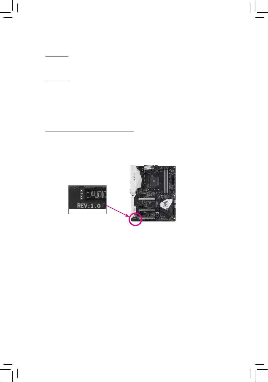
The revision number on your motherboard looks like this: «REV: X.X.» For example, «REV:
1.0″ means the revision of the motherboard is 1.0. Check your motherboard revision before
updating motherboard BIOS, drivers, or when looking for technical information.
Example:

— 3 —
Table of Contents
B450M DS3H V2 Motherboard Layout ………………………………………………………………….4
Chapter 1 Hardware Installation ………………………………………………………………………….5
1-1 Installation Precautions ………………………………………………………………………… 5
1-2 ProductSpecications ………………………………………………………………………….. 6
1-3 Installing the CPU ……………………………………………………………………………….. 9
1-4 Installing the Memory …………………………………………………………………………… 9
1-5 Installing an Expansion Card ………………………………………………………………. 10
1-6 Back Panel Connectors ………………………………………………………………………. 10
1-7 Internal Connectors ……………………………………………………………………………. 12
Chapter 2 BIOS Setup ……………………………………………………………………………………..19
2-1 Startup Screen ………………………………………………………………………………….. 19
2-2 The Main Menu …………………………………………………………………………………. 20
2-3 M.I.T. ……………………………………………………………………………………………….. 21
2-4 System …………………………………………………………………………………………….. 25
2-5 BIOS ………………………………………………………………………………………………… 26
2-6 Peripherals ……………………………………………………………………………………….. 29
2-7 Chipset …………………………………………………………………………………………….. 32
2-8 Power ………………………………………………………………………………………………. 34
2-9 Save & Exit ……………………………………………………………………………………….. 36
Chapter 3 Appendix …………………………………………………………………………………………37
3-1 ConguringaRAIDSet ………………………………………………………………………. 37
3-2 Drivers Installation ……………………………………………………………………………… 39
RegulatoryNotices ………………………………………………………………………………………. 40
Contact Us …………………………………………………………………………………………………. 41
— 4 —
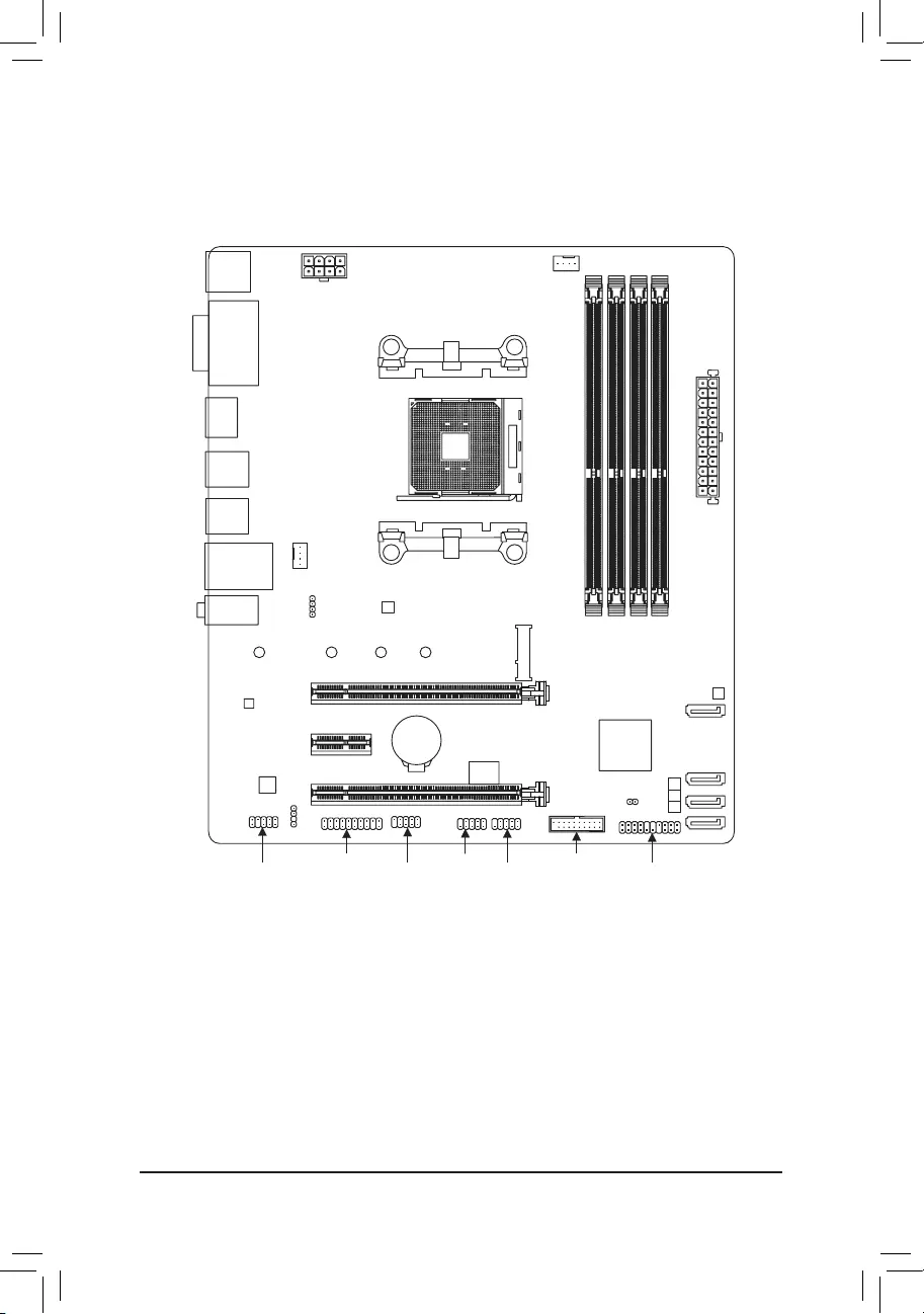
B450M DS3H V2 Motherboard Layout
* The box contents above are for reference only and the actual items shall depend on the product package you obtain.
The box contents are subject to change without notice.
Box Contents
5B450M DS3H V2 Motherboard 5Two SATA cables
5Motherboard driver disc 5I/O Shield
5User’s Manual
KB_MS_USB CPU_FAN
SYS_FAN1
ATX
B450M DS3H V2
AUDIO
DDR4_4
DDR4_1
BAT
ATX_12V
AMD
B450
R_USB30_1
HDMI
CODEC
M_BIOS
DVI
PCIEX16
PCIEX1
iTE®
Super I/O
Realtek®
GbELAN
F_USB30
F_USB1 F_PANEL
F_USB2
LED_CPU
SATA3
012
USB_LAN
Socket AM4
R_USB30_2
3
CLR_CMOS
M2A_SOCKET
80 60 42110
SATA3
DDR4_2
DDR4_3
COM
TPM
SPDIF_O
F_AUDIO
PCIEX4

Chapter 1 Hardware Installation
1-1 Installation Precautions
The motherboard contains numerous delicate electronic circuits and components which can become
damaged as a result of electrostatic discharge (ESD). Prior to installation, carefully read the user’s
manual and follow these procedures:
•Prior to installation, make sure the chassis is suitable for the motherboard.
•Priortoinstallation,donotremoveorbreakmotherboardS/N(SerialNumber)stickeror
warranty sticker provided by your dealer. These stickers are required for warranty validation.
•Always remove the AC power by unplugging the power cord from the power outlet before
installing or removing the motherboard or other hardware components.
•When connecting hardware components to the internal connectors on the motherboard, make
sure they are connected tightly and securely.
•When handling the motherboard, avoid touching any metal leads or connectors.
•It is best to wear an electrostatic discharge (ESD) wrist strap when handling electronic
components such as a motherboard, CPU or memory. If you do not have an ESD wrist strap,
keepyourhandsdryandrsttouchametalobjecttoeliminatestaticelectricity.
•Prior to installing the motherboard, please have it on top of an antistatic pad or within an
electrostatic shielding container.
•Before connecting or unplugging the power supply cable from the motherboard, make sure
the power supply has been turned off.
•Before turning on the power, make sure the power supply voltage has been set according to
the local voltage standard.
•Before using the product, please verify that all cables and power connectors of your hardware
components are connected.
•To prevent damage to the motherboard, do not allow screws to come in contact with the
motherboard circuit or its components.
•Make sure there are no leftover screws or metal components placed on the motherboard or
within the computer casing.
•Do not place the computer system on an uneven surface.
•Do not place the computer system in a high-temperature or wet environment.
•Turning on the computer power during the installation process can lead to damage to system
components as well as physical harm to the user.
•If you are uncertain about any installation steps or have a problem related to the use of the
product,pleaseconsultacertiedcomputertechnician.
•If you use an adapter, extension power cable, or power strip, ensure to consult with its installation
and/or grounding instructions.
— 5 —
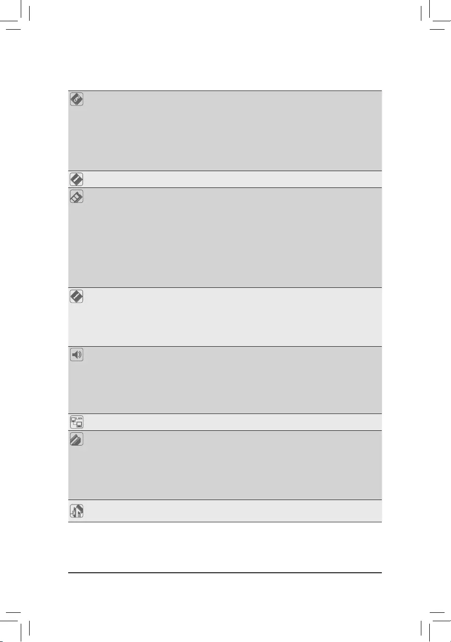
1-2 ProductSpecications
CPU AM4 Socket:
- AMD3rdGenerationRyzen™ processors
- AMD2ndGenerationRyzen™ processors
- AMD1stGenerationRyzen™ processors
- AMD2ndGenerationRyzen™withRadeon™ Vega Graphics processors
- AMD1stGenerationRyzen™withRadeon™ Vega Graphics processors
— AMD Athlon™withRadeon™ Vega Graphics processors
(Go to GIGABYTE’s website for the latest CPU support list.)
Chipset AMD B450
Memory 4xDDR4DIMMsocketssupportingupto128GB(32GBsingleDIMMcapacity)
of system memory
Dual channel memory architecture
SupportforDDR42933/2667/2400/2133MHzmemorymodules
SupportforECCUn-bufferedDIMM 1Rx8/2Rx8memorymodules(operate in
non-ECC mode)
Supportfornon-ECCUn-bufferedDIMM1Rx8/2Rx8/1Rx16memorymodules
SupportforExtremeMemoryProle(XMP)memorymodules
(Go to GIGABYTE’s website for the latest supported memory speeds and memory
modules.)
Onboard
Graphics
Integrated Graphics Processor:
- 1xDVI-Dport,supportingamaximumresolutionof1920×1200@60Hz
* The DVI-D port does not support D-Sub connection by adapter.
- 1xHDMIport,supportingamaximumresolutionof4096×2160@60Hz(Note)
* Support for HDMI 2.0 version and HDCP 2.2.(Note)
Maximum shared memory of 16 GB
Audio Realtek® ALC887 codec
HighDenitionAudio
2/4/5.1/7.1-channel
* Tocongure7.1-channelaudio,youneedtoopentheaudiosoftwareandselect
Deviceadvanced settings > Playback Device to change the default settingrst.
PleasevisitGIGABYTE’swebsitefordetailsonconguringtheaudiosoftware.
Support for S/PDIF Out
LAN Realtek®GbELANchip(1000/100Mbit)
Expansion Slots 1 x PCI Express x16 slot, running at x16 (PCIEX16) (Note)
* For optimum performance, if only one PCI Express graphics card is to be installed,
be sure to install it in the PCIEX16 slot.
(The PCIEX16 slot conforms to PCI Express 3.0 standard.)
1 x PCI Express x16 slot, running at x4 (PCIEX4)
1 x PCI Express x1 slot
(The PCIEX4 and PCI Express x1 slots conform to PCI Express 2.0 standard.)
Multi-Graphics
Technology Support for AMD Quad-GPU CrossFire™ and 2-Way AMD CrossFire™ technologies
(Note) ActualsupportmayvarybyCPU.
— 6 —
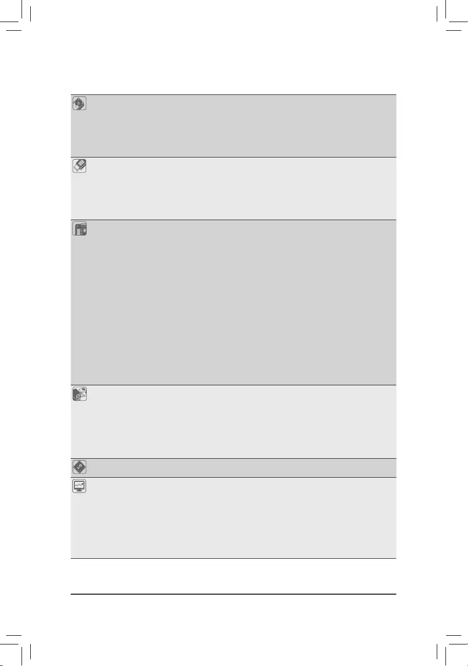
Storage Interface 1 x M.2 connector (Socket 3, M key, type 2242/2260/2280/22110 SATA and
PCIe 3.0 x4/x2 SSD support)
4 x SATA 6Gb/s connectors
SupportforRAID0,RAID1,andRAID10
* Referto»1-7InternalConnectors,»fortheinstallationnoticesfortheM.2andSATA
connectors.
USB Chipset:
— 2 x USB 3.1 Gen 1 ports available through the internal USB header
— 8 x USB 2.0/1.1 ports (4 ports on the back panel, 4 ports available through
the internal USB headers)
CPU:
— 4 x USB 3.1 Gen 1 ports on the back panel
Internal
Connectors
1 x 24-pin ATX main power connector
1 x 8-pin ATX 12V power connector
1 x CPU fan header
1 x system fan header
1 x M.2 Socket 3 connector
4 x SATA 6Gb/s connectors
1 x front panel header
1 x front panel audio header
1 x S/PDIF Out header
1xCPUcoolerLEDstrip/RGBLEDstripheader
1 x USB 3.1 Gen 1 header
2 x USB 2.0/1.1 headers
1 x Trusted Platform Module (TPM) header (2×10 pin, for the GC-TPM2.0 module
only)
1 x serial port header
1 x Clear CMOS jumper
Back Panel
Connectors
1 x PS/2 keyboard/mouse port
1 x DVI-D port
1 x HDMI port
4 x USB 3.1 Gen 1 ports
4 x USB 2.0/1.1 ports
1xRJ-45port
3 x audio jacks
I/O Controller iTE® I/O Controller Chip
Hardware
Monitor
Voltage detection
Temperature detection
Fan speed detection
Overheating warning
Fan fail warning
Fan speed control
* Whether the fan speed control function is supported will depend on the cooler you
install.
— 7 —
BIOS 1x128Mbitash
Use of licensed AMI UEFI BIOS
PnP 1.0a, DMI 2.7, WfM 2.0, SM BIOS 2.7, ACPI 5.0
Unique Features Support for APP Center
* Available applications in APP Center may vary by motherboard model. Supported
functionsofeachapplicationmayalsovarydependingonmotherboardspecications.
— @BIOS
— EasyTune
— Fast Boot
— Game Boost
- ON/OFFCharge
- RGBFusion
— Smart Backup
— System Information Viewer
Support for Q-Flash
Support for Xpress Install
Bundled
Software
Norton® Internet Security (OEM version)
cFosSpeed
Operating
System Support for Windows 10 64-bit
Form Factor Micro ATX Form Factor; 24.4cm x 21.5cm
* GIGABYTEreservestherighttomakeanychangestotheproductspecicationsandproduct-relatedinformationwithout
prior notice.
Please visit GIGABYTE’s website
for support lists of CPU, memory
modules, SSDs, and M.2 devices.
Please visit the Support\Utility List
page on GIGABYTE’s website to
download the latest version of apps.
— 8 —

1-3 Installing the CPU
Please visit GIGABYTE’s website for details on hardware installation.
1-4 Installing the Memory
Readthefollowingguidelinesbeforeyoubegintoinstallthememory:
•Make sure that the motherboard supports the memory. It is recommended that memory of the
same capacity, brand, speed, and chips be used.
(Go to GIGABYTE’s website for the latest supported memory speeds and memory modules.)
•Always turn off the computer and unplug the power cord from the power outlet before installing the
memory to prevent hardware damage.
•Memory modules have a foolproof design. A memory module can be installed in only one direction.
If you are unable to insert the memory, switch the direction.
ReadthefollowingguidelinesbeforeyoubegintoinstalltheCPU:
•Make sure that the motherboard supports the CPU.
(Go to GIGABYTE’s website for the latest CPU support list.)
•Always turn off the computer and unplug the power cord from the power outlet before installing the
CPU to prevent hardware damage.
•Locate the pin one of the CPU. The CPU cannot be inserted if oriented incorrectly.
•Apply an even and thin layer of thermal grease on the surface of the CPU.
•Do not turn on the computer if the CPU cooler is not installed, otherwise overheating and damage
of the CPU may occur.
•SettheCPUhostfrequencyinaccordancewiththeCPUspecications.Itisnotrecommended
thatthesystembusfrequencybesetbeyondhardwarespecicationssinceitdoesnotmeetthe
standard requirements for the peripherals. If you wish to set the frequency beyond the standard
specications,pleasedosoaccordingtoyourhardwarespecicationsincludingtheCPU,graphics
card, memory, hard drive, etc.
DualChannelMemoryConguration
This motherboard provides four memory sockets and supports Dual Channel Technology. After the memory
isinstalled,theBIOSwillautomaticallydetectthespecicationsandcapacityofthememory.EnablingDual
Channel memory mode will double the original memory bandwidth.
The four memory sockets are divided into two channels and each channel has two memory sockets as following:
ChannelA:DDR4_2,DDR4_4
ChannelB:DDR4_1,DDR4_3
Installing the CPU
Completely lift up the CPU socket locking lever. Locate the pin one (denoted by a small triangle) of the CPU
socketandtheCPU.OncetheCPUispositionedintoitssocket,placeonengerdownonthemiddleofthe
CPU, lowering the locking lever and latching it into the fully locked position.
AM4 Socket
A Small Triangle
Marking Denotes Pin
One of the Socket AM4 CPU
A Small Triangle
Marking Denotes CPU
Pin One
— 9 —
1-5 Installing an Expansion Card
Readthefollowingguidelinesbeforeyoubegintoinstallanexpansioncard:
•Make sure the motherboard supports the expansion card. Carefully read the manual that came
with your expansion card.
•Always turn off the computer and unplug the power cord from the power outlet before installing an
expansion card to prevent hardware damage.
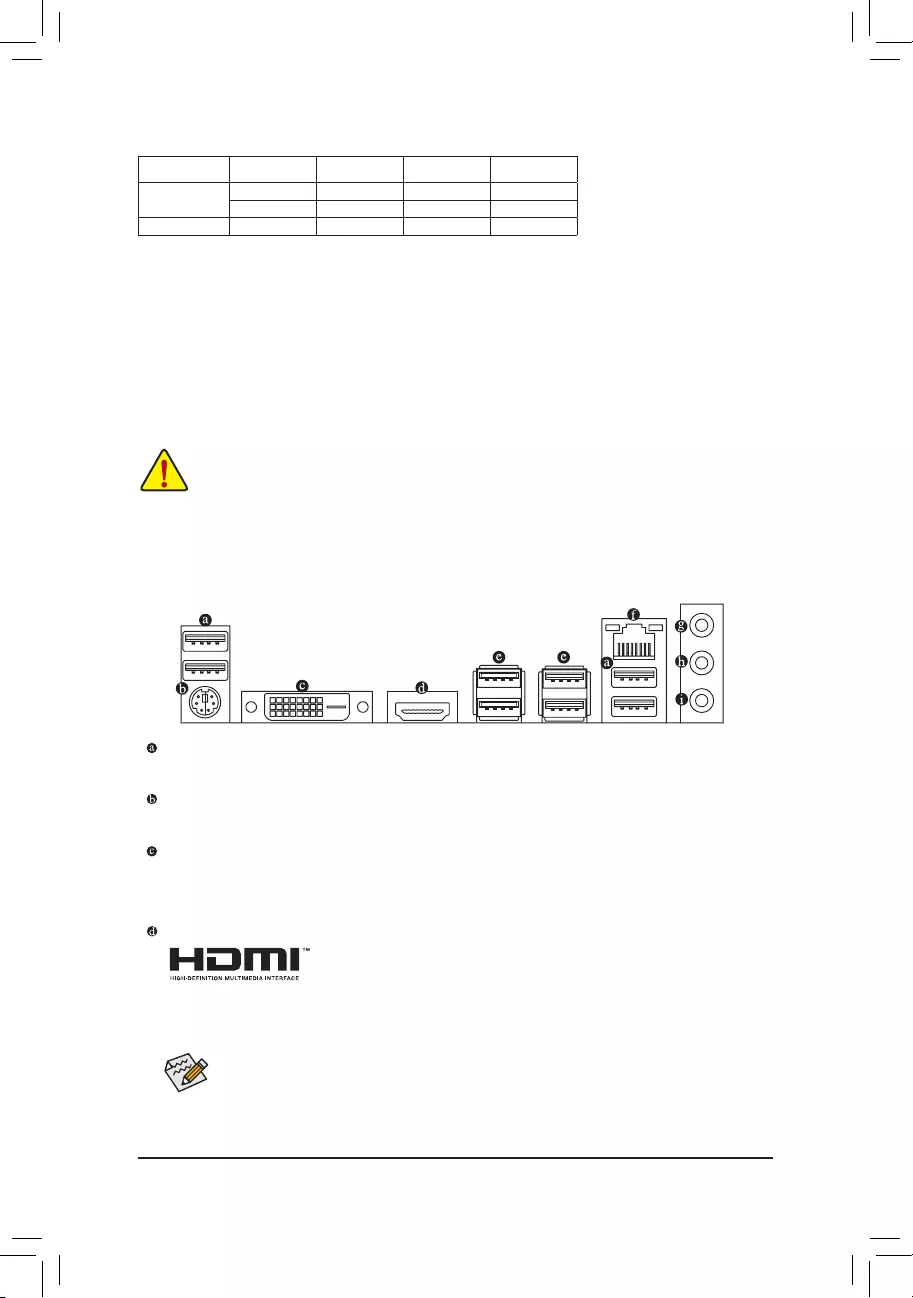
1-6 Back Panel Connectors
USB 2.0/1.1 Port
TheUSBportsupportstheUSB2.0/1.1specication.UsethisportforUSBdevices.
PS/2 Keyboard/Mouse Port
Use this port to connect a PS/2 mouse or keyboard.
DVI-D Port (Note 1)
TheDVI-DportconformstotheDVI-Dspecicationandsupportsamaximumresolutionof1920×1200@60Hz
(the actual resolutions supported depend on the monitor being used). Connect a monitor that supports
DVI-D connection to this port.
HDMI Port
The HDMI port supports HDCP 2.2 (Note2) and Dolby TrueHD and DTS HD
MasterAudioformats.Italsosupportsupto192KHz/24bit7.1-channelLPCM
audio output. You can use this port to connect your HDMI-supported monitor. The maximum supported
resolutionis4096×2160@60Hz(Note 2), but the actual resolutions supported are dependent on the
monitor being used.
After installing the HDMI device, make sure to set the default sound playback device to HDMI. (The
item name may differ depending on your operating system.)
Due to CPU limitations, read the following guidelines before installing the memory in Dual Channel mode.
1. Dual Channel mode cannot be enabled if only one memory module is installed.
2. When enabling Dual Channel mode with two or four memory modules, it is recommended that memory
of the same capacity, brand, speed, and chips be used. For optimum performance, when enabling
DualChannelmodewithtwomemorymodules,werecommendthatyouinstallthemintheDDR4_1
andDDR4_2sockets.
DualChannelMemoryCongurationsTable
DDR4_4 DDR4_2 DDR4_3 DDR4_1
2 Modules — — DS/SS — — DS/SS
DS/SS — — DS/SS — —
4 Modules DS/SS DS/SS DS/SS DS/SS
(SS=Single-Sided,DS=Double-Sided,»--«=NoMemory)
(Note1) TheDVI-DportdoesnotsupportD-Subconnectionbyadapter.
(Note2) ActualsupportmayvarybyCPU.
— 10 —
Tocongure7.1-channelaudio,youneedtoopentheaudiosoftwareandselectDeviceadvanced
settings>PlaybackDevicetochangethedefaultsettingrst.PleasevisitGIGABYTE’swebsitefor
detailsonconguringtheaudiosoftware.
•Whenremovingthecableconnectedtoabackpanelconnector,rstremovethecablefromyour
device and then remove it from the motherboard.
•When removing the cable, pull it straight out from the connector. Do not rock it side to side to
prevent an electrical short inside the cable connector.
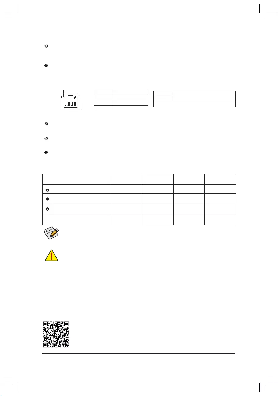
Line In/Rear Speaker Out (Blue)
The line in jack. Use this audio jack for line in devices such as an optical drive, walkman, etc.
Line Out/Front Speaker Out (Green)
The line out jack.
Mic In/Center/Subwoofer Speaker Out (Pink)
The Mic in jack.
AudioJackCongurations:
Jack Headphone/
2-channel 4-channel 6-channel 8-channel
LineIn/RearSpeakerOut aaa
Line Out/Front Speaker Out aaaa
Mic In/Center/Subwoofer Speaker
Out a a
Front Panel Line Out/Side Speaker
Out a
PleasevisitGIGABYTE’swebsitefordetailsonconguringtheaudiosoftware.
USB 3.1 Gen 1 Port
TheUSB3.1Gen1portsupportstheUSB3.1Gen1specicationandiscompatibletotheUSB2.0
specication.UsethisportforUSBdevices.
RJ-45 LAN Port
TheGigabitEthernetLANportprovidesInternetconnectionatup to 1 Gbps data rate.Thefollowing
describesthestatesoftheLANportLEDs.
Activity LED
Connection/
Speed LED
LANPort
Activity LED:
Connection/Speed LED:
State Description
Orange 1 Gbps data rate
Green 100 Mbps data rate
Off 10 Mbps data rate
State Description
Blinking Data transmission or receiving is occurring
Off Nodatatransmissionorreceivingisoccurring
— 11 —
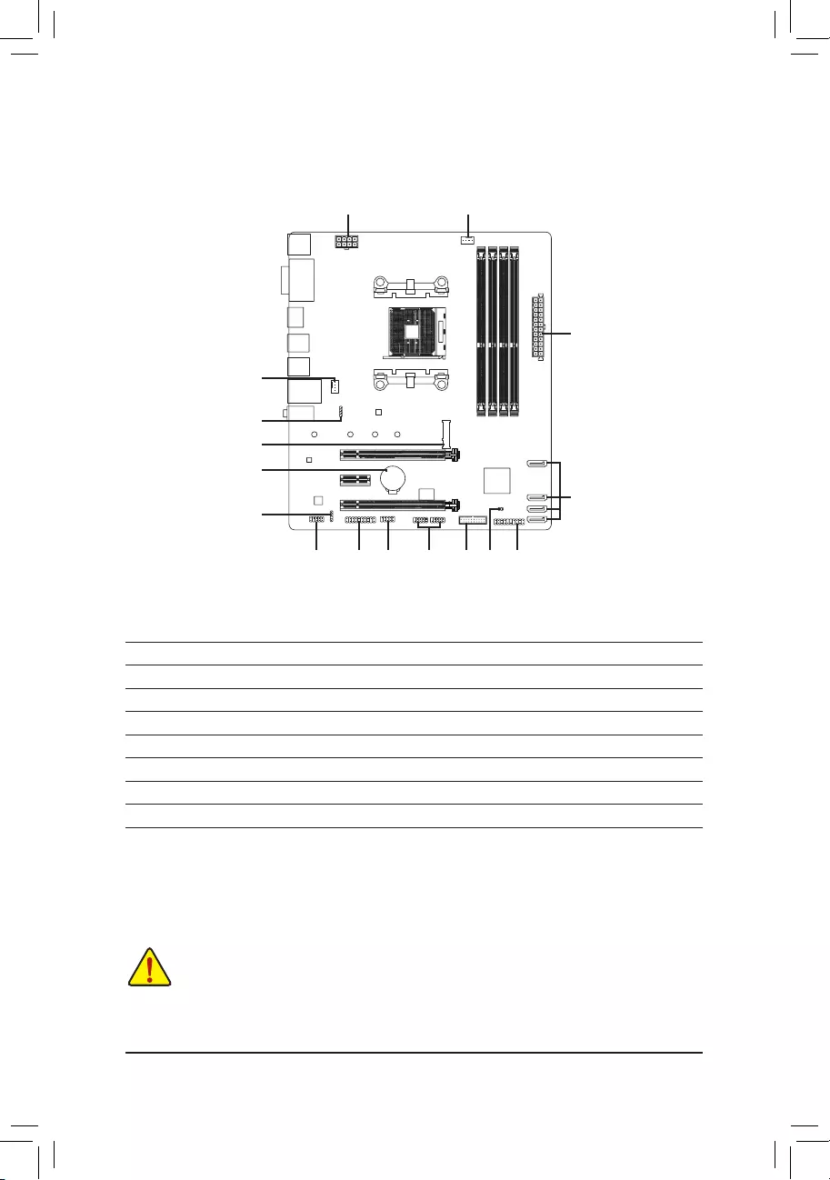
1-7 Internal Connectors
Readthefollowingguidelinesbeforeconnectingexternaldevices:
•First make sure your devices are compliant with the connectors you wish to connect.
•Before installing the devices, be sure to turn off the devices and your computer. Unplug the power
cord from the power outlet to prevent damage to the devices.
•After installing the device and before turning on the computer, make sure the device cable has
been securely attached to the connector on the motherboard.
1) ATX_12V
2) ATX
3) CPU_FAN
4) SYS_FAN1
5) LED_CPU
6) SATA3 0/1/2/3
7) M2A_SOCKET
 SPDIF_O
9) F_PANEL
10) F_ AUDIO
11) F_USB30
12) F_USB1/F_USB2
13) COM
14) TPM
15) BAT
16) CLR_CMOS
1
2
3
11
5
13
10 14
7
4
6
12 916
15
8
— 12 —
131
2412
ATX
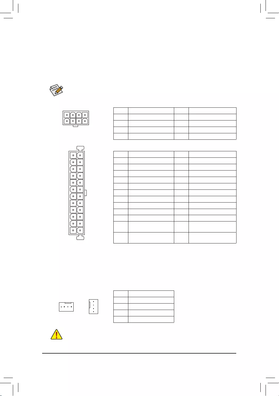
1/2) ATX_12V/ATX (2×4 12V Power Connector and 2×12 Main Power Connector)
With the use of the power connector, the power supply can supply enough stable power to all the components
onthemotherboard.Beforeconnectingthepowerconnector,rstmakesurethepowersupplyisturned
off and all devices are properly installed. The power connector possesses a foolproof design. Connect the
power supply cable to the power connector in the correct orientation.
The 12V power connector mainly supplies power to the CPU. If the 12V power connector is not connected,
the computer will not start.
To meet expansion requirements, it is recommended that a power supply that can withstand high
power consumption be used (500W or greater). If a power supply is used that does not provide the
required power, the result can lead to an unstable or unbootable system.
ATX:
PinNo. Denition PinNo. Denition
1 3.3V 13 3.3V
2 3.3V 14 -12V
3GND 15 GND
4 +5V 16 PS_ON(softOn/Off)
5GND 17 GND
6 +5V 18 GND
7GND 19 GND
8 Power Good 20 NC
9 5VSB (stand by +5V) 21 +5V
10 +12V 22 +5V
11 +12V (Only for 2×12-pin
ATX)
23 +5V (Only for 2×12-pin ATX)
12 3.3V (Only for 2×12-pin
ATX)
24 GND(Onlyfor2×12-pinATX)
ATX_12V:
PinNo. Denition PinNo. Denition
1GND(Onlyfor2×4-pin12V) 5 +12V (Only for 2×4-pin 12V)
2GND(Onlyfor2×4-pin12V) 6 +12V (Only for 2×4-pin 12V)
3GND 7 +12V
4GND 8 +12V
ATX_12V
58
14
•Be sure to connect fan cables to the fan headers to prevent your CPU and system from
overheating. Overheating may result in damage to the CPU or the system may hang.
•Thesefanheadersarenotcongurationjumperblocks.Donotplaceajumpercapontheheaders.
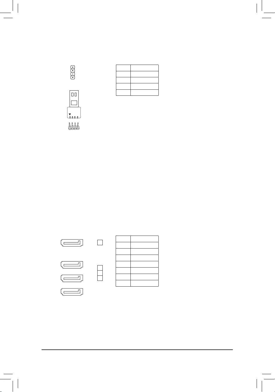
3/4) CPU_FAN/SYS_FAN1 (Fan Headers)
All fan headers on this motherboard are 4-pin. Most fan headers possess a foolproof insertion design.
When connecting a fan cable, be sure to connect it in the correct orientation (the black connector wire
is the ground wire). The motherboard supports CPU fan speed control, which requires the use of a CPU
fan with fan speed control design. For optimum heat dissipation, it is recommended that a system fan be
installed inside the chassis.
CPU_FAN
1
SYS_FAN1
1PinNo. Denition
1GND
2 Voltage Speed Control
3 Sense
4 PWM Speed Control
— 13 —
PinNo. Denition
1 12V
2GND
3R
4 B
1
5) LED_CPU (CPU Cooler LED Strip/RGB LED Strip Header)
TheheadercanbeusedtoconnectaCPUcoolerLEDstriporastandard5050RGBLEDstrip(12V/G/R/B),
with maximum power rating of 2A (12V) and maximum length of 2m.
ConnecttheCPUcoolerLEDstrip/RGBLEDstriptotheheader.The
power pin (marked with a triangle on the plug) of the LED strip must be
connected to Pin 1 (12V) of this header. Incorrect connection may lead
to the damage of the LED strip.
RGB
LED Strip
1
12V
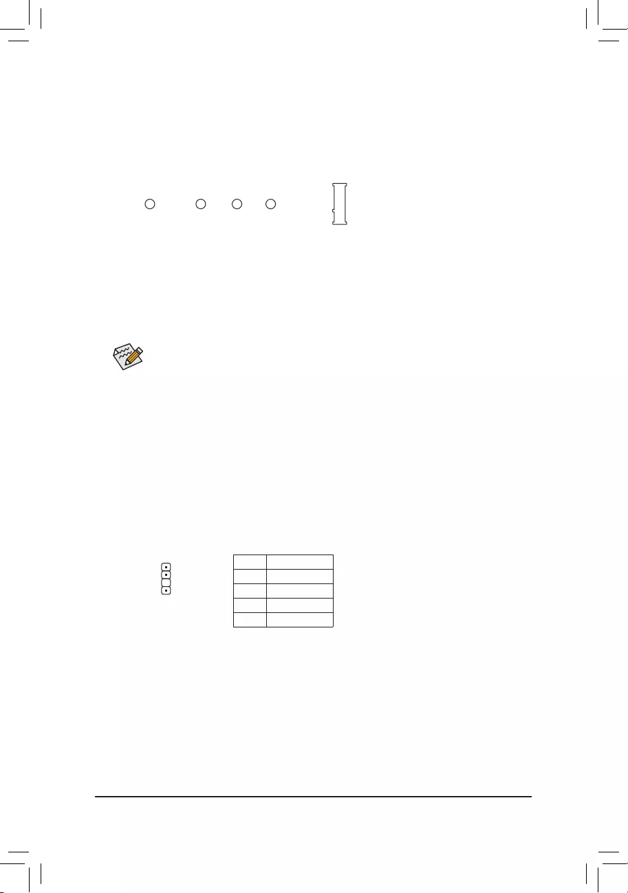
6) SATA3 0/1/2/3 (SATA 6Gb/s Connectors)
The SATA connectors conform to SATA 6Gb/s standard and are compatible with SATA 3Gb/s and SATA
1.5Gb/s standard. Each SATA connector supports a single SATA device. The SATA connectors support
RAID0,RAID1,andRAID10.RefertoChapter3,»ConguringaRAIDSet,»forinstructionsonconguring
aRAIDarray.
PinNo. Denition
1GND
2 TXP
3TXN
4GND
5RXN
6RXP
7GND
SATA3
2
1
0
71
71
71
71
3
— 14 —
7) M2A_SOCKET (M.2 Socket 3 Connector)
TheM.2connectorssupportM.2SATASSDsorM.2PCIeSSDsandsupportRAIDconguration.Please
notethatanM.2PCIeSSDcannotbeusedtocreateaRAIDseteitherwithaSATAharddrive.Tocreatea
RAIDarraywithanM.2PCIeSSD,youmustsetupthecongurationinUEFIBIOSmode.RefertoChapter
3,»ConguringaRAIDSet,»forinstructionsonconguringaRAIDarray.
Follow the steps below to correctly install an M.2 SSD in the M.2 connector.
Step 1:
Use a screw driver to unfasten the screw and nut from the motherboard. Locate the proper mounting hole
fortheM.2SSDtobeinstalledandthenscrewthenutrst.
Slide the M.2 SSD into the connector at an angle.
Step 2:
Press the M.2 SSD down and then secure it with the screw.
Select the proper hole for the M.2 SSD to be installed and refasten the screw and nut.
F_USB30 F_U
B_
F_ F_
_
B
BS_
B
SB_
B
_S
S_
_
B
_U
_
B
S
123
123
123
123
1
1
1
1
BSS
S
_S
SSU
1 2 3
S3 BSSS
U
__ 3
F_USB3F
S _
S _
S _
SF
B_
B_
F
_0
S
S
_0F
_F
_
_
__B
U
S _S
_ SF_
USB0_B
B_ F_USB3
F_USB303
_
_3U
80110 60 42
SPDIF_O (S/PDIF Out Header)
This header supports digital S/PDIF Out and connects a S/PDIF digital audio cable (provided by expansion
cards) for digital audio output from your motherboard to certain expansion cards like graphics cards and
sound cards. For example, some graphics cards may require you to use a S/PDIF digital audio cable for
digital audio output from your motherboard to your graphics card if you wish to connect an HDMI display
to the graphics card and have digital audio output from the HDMI display at the same time. For information
about connecting the S/PDIF digital audio cable, carefully read the manual for your expansion card.
1
F_USB30 F_U
B_
F_ F_
_
B
BS_
B
SB_
B
_S
S_
_
B
_U
_
B
S
123
123
123
123
1
1
1
1
BSS
S
_S
SSU
1 2 3
S3 BSSS
U
__ 3
F_USB3F
S _
S _
S _
SF
B_
B_
F
_0
S
S
_0F
_F
_
_
__B
U
S _S
_ SF_
USB0_B
B_ F_USB3
F_USB303
_
_3U
PinNo. Denition
1 5VDUAL
2NoPin
3 SPDIFO
4GND
— 15 —
The front panel design may differ by chassis. A front panel module mainly consists of power switch,
reset switch, power LED, hard drive activity LED, speaker and etc. When connecting your chassis
front panel module to this header, make sure the wire assignments and the pin assignments are
matched correctly.
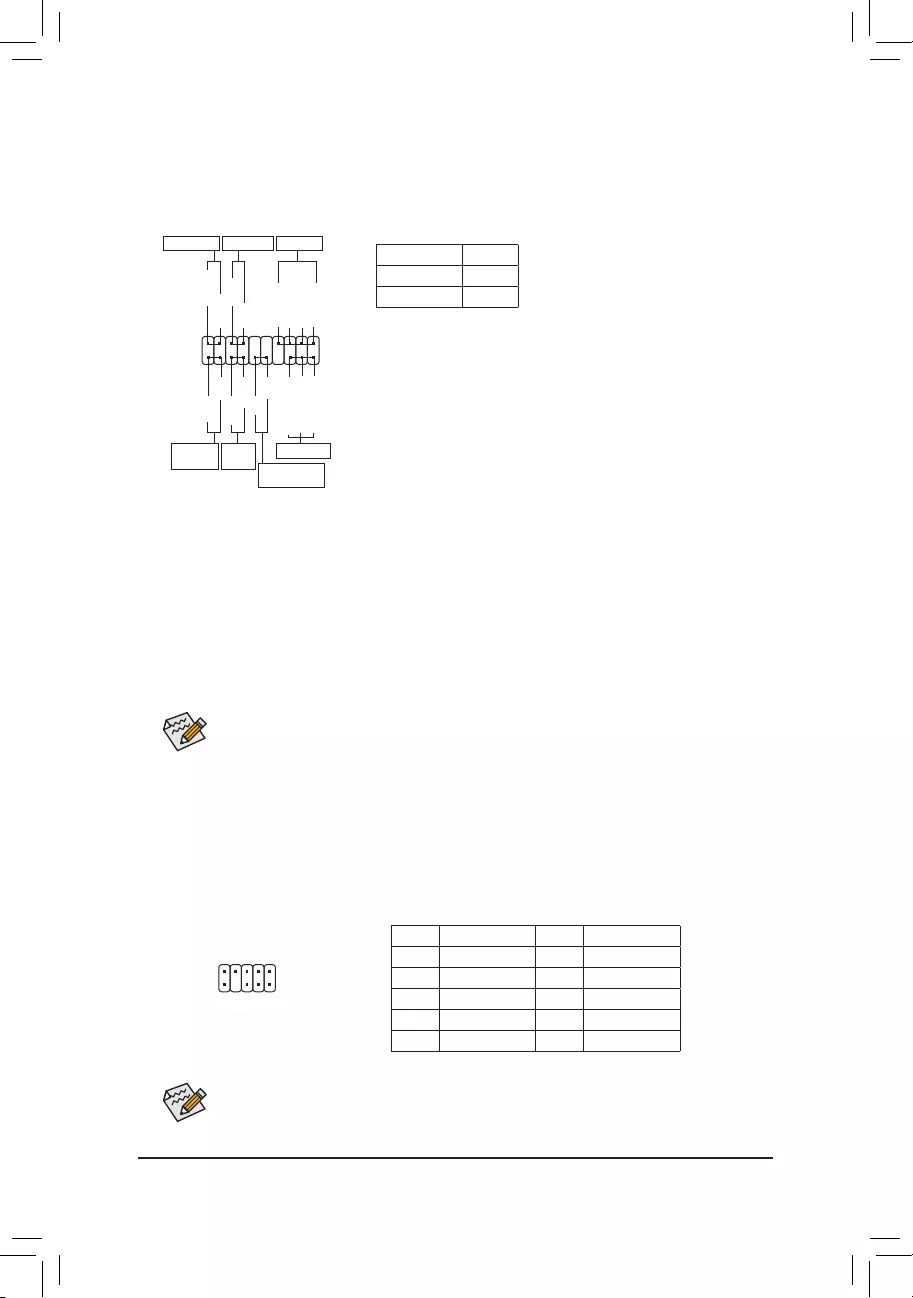
9) F_PANEL (Front Panel Header)
Connect the power switch, reset switch, speaker, chassis intrusion switch/sensor and system status indicator
onthechassistothisheaderaccordingtothepinassignmentsbelow.Notethepositiveandnegativepins
before connecting the cables.
System Status LED
S0 On
S3/S4/S5 Off
•PW (Power Switch):
Connects to the power switch on the chassis front panel. You may
congure the way to turn off your system using thepower switch
(referto Chapter 2,«BIOSSetup,»«PowerManagement,»formore
information).
•SPEAK (Speaker):
Connects to the speaker on the chassis front panel. The system reports
system startup status by issuing a beep code. One single short beep
will be heard if no problem is detected at system startup.
•PLED/PWR_LED (Power LED):
Connects to the power status indicator
on the chassis front panel. The LED is on
when the system is operating. The LED is
off when the system is in S3/S4 sleep state
or powered off (S5).
•HD (Hard Drive Activity LED):
Connects to the hard drive activity LED on the chassis front panel. The LED is on when the hard drive is
reading or writing data.
•RES (ResetSwitch):
Connects to the reset switch on the chassis front panel. Press the reset switch to restart the computer if the
computerfreezesandfailstoperformanormalrestart.
•CI (Chassis Intrusion Header):
Connects to the chassis intrusion switch/sensor on the chassis that can detect if the chassis cover has been
removed. This function requires a chassis with a chassis intrusion switch/sensor.
•NC: Noconnection.
10) F_AUDIO (Front Panel Audio Header)
ThefrontpanelaudioheadersupportsHighDenitionaudio(HD).Youmayconnectyourchassisfront
panel audio module to this header. Make sure the wire assignments of the module connector match the
pin assignments of the motherboard header. Incorrect connection between the module connector and the
motherboard header will make the device unable to work or even damage it.
Some chassis provide a front panel audio module that has separated connectors on each wire
instead of a single plug. For information about connecting the front panel audio module that has
different wire assignments, please contact the chassis manufacturer.
1
2
9
10
PinNo. Denition PinNo. Denition
1 MIC2_L 6 Sense
2GND 7FAUDIO_JD
3MIC2_R 8NoPin
4NC 9LINE2_L
5LINE2_R 10 Sense
SPEAK+
SPEAK-
Speaker
NC
NC
Hard Drive
Activity LED
1
2
19
20
CI-
CI+
PLED-
PW-
PLED+
PW+
HD-
RES+
HD+
RES-
Reset
Switch Chassis Intrusion
Header
Power Switch
F_USB30 F_U
B_
F_ F_
_
B
BS_
B
SB_
B
_S
S_
_
B
_U
_
B
S
123
123
123
123
1
1
1
1
BSS
S
_S
SSU
1 2 3
S3 BSSS
U
__ 3
F_USB3F
S _
S _
S _
SF
B_
B_
F
_0
S
S
_0F
_F
_
_
__B
U
S _S
_ SF_
USB0_B
B_ F_USB3
F_USB303
_
_3U
Power LED
Power LED
PWR_LED-
PWR_LED+
PWR_LED-
— 16 —
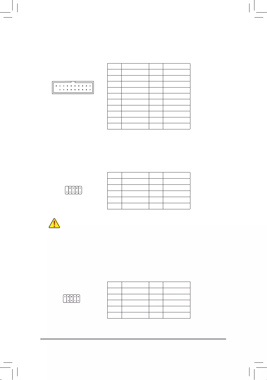
PinNo. Denition PinNo. Denition
1 VBUS 11 D2+
2SSRX1- 12 D2-
3SSRX1+ 13 GND
4GND 14 SSTX2+
5 SSTX1- 15 SSTX2-
6 SSTX1+ 16 GND
7GND 17 SSRX2+
8 D1- 18 SSRX2-
9 D1+ 19 VBUS
10 NC 20 NoPin
11) F_USB30 (USB 3.1 Gen 1 Header)
TheheaderconformstoUSB3.1Gen1andUSB2.0specicationandcanprovidetwoUSBports.For
purchasingtheoptional3.5″frontpanelthatprovidestwoUSB3.1Gen1ports,pleasecontactthelocal
dealer.
F_USB30 F_U
B_
F_ F_
_
B
BS_
B
SB_
B
_S
S_
_
B
_U
_
B
S
123
123
123
123
1
1
1
1
BSS
S
_S
SSU
1 2 3
S3 BSSS
U
__ 3
F_USB3F
S _
S _
S _
SF
B_
B_
F
_0
S
S
_0F
_F
_
_
__B
U
S _S
_ SF_
USB0_B
B_ F_USB3
F_USB303
_
_3U
10
11
1
20
12) F_USB1/F_USB2 (USB 2.0/1.1 Headers)
TheheadersconformtoUSB2.0/1.1specication.EachUSBheadercanprovidetwoUSBportsviaan
optional USB bracket. For purchasing the optional USB bracket, please contact the local dealer.
PinNo. Denition PinNo. Denition
1 Power (5V) 6 USB DY+
2 Power (5V) 7 GND
3 USB DX- 8 GND
4 USB DY— 9 NoPin
5 USB DX+ 10 NC
•Do not plug the IEEE 1394 bracket (2×5-pin) cable into the USB 2.0/1.1 header.
•Prior to installing the USB bracket, be sure to turn off your computer and unplug the power cord
from the power outlet to prevent damage to the USB bracket.
10
9
2
1
13) COM (Serial Port Header)
The COM header can provide one serial port via an optional COM port cable. For purchasing the optional
COM port cable, please contact the local dealer.
PinNo. Denition PinNo. Denition
1NDCD- 6NDSR-
2NSIN 7NRTS-
3NSOUT 8NCTS-
4NDTR- 9NRI-
5GND 10 NoPin
10
9
2
1
— 17 —
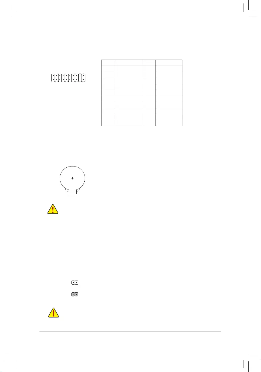
14) TPM (Trusted Platform Module Header)
You may connect a TPM (Trusted Platform Module) to this header.
20
19
2
1
PinNo. Denition PinNo. Denition
1 LCLK 11 LAD0
2GND 12 GND
3LFRAME 13 NC
4NoPin 14 NC
5LRESET 15 SB3V
6NC 16 SERIRQ
7 LAD3 17 GND
8 LAD2 18 NC
9 VCC3 19 NC
10 LAD1 20 NC
15) BAT (Battery)
Thebatteryprovidespowertokeepthevalues(suchasBIOScongurations,date,andtimeinformation)
intheCMOSwhenthecomputeristurnedoff.Replacethebatterywhenthebatteryvoltagedropstoalow
level, or the CMOS values may not be accurate or may be lost.
You may clear the CMOS values by removing the battery:
1. Turn off your computer and unplug the power cord.
2. Gently remove the battery from the battery holder and wait for one minute. (Or
use a metal object like a screwdriver to touch the positive and negative terminals
of the battery holder, making them short for 5 seconds.)
3. Replacethebattery.
4. Plug in the power cord and restart your computer.
•Always turn off your computer and unplug the power cord before replacing the battery.
•Replacethebatterywithanequivalentone.Damagetoyourdevicesmayoccurifthebatteryis
replaced with an incorrect model.
•Contact the place of purchase or local dealer if you are not able to replace the battery by yourself
or uncertain about the battery model.
•When installing the battery, note the orientation of the positive side (+) and the negative side (-)
of the battery (the positive side should face up).
•Used batteries must be handled in accordance with local environmental regulations.
16) CLR_CMOS (Clear CMOS Jumper)
UsethisjumpertocleartheBIOScongurationandresettheCMOSvaluestofactorydefaults.Toclear
the CMOS values, use a metal object like a screwdriver to touch the two pins for a few seconds.
•Always turn off your computer and unplug the power cord from the power outlet before clearing
the CMOS values.
•Aftersystemrestart,gotoBIOSSetuptoloadfactorydefaults(selectLoadOptimizedDefaults)or
manuallyconguretheBIOSsettings(refertoChapter2,«BIOSSetup,»forBIOScongurations).
Open:Normal
Short: Clear CMOS Values
— 18 —
Chapter 2 BIOS Setup
BIOS (Basic Input and Output System) records hardware parameters of the system in the CMOS on the
motherboard. Its major functions include conducting the Power-On Self-Test (POST) during system startup,
saving system parameters and loading operating system, etc. BIOS includes a BIOS Setup program that allows
theusertomodifybasicsystemcongurationsettingsortoactivatecertainsystemfeatures.
When the power is turned off, the battery on the motherboard supplies the necessary power to the CMOS to
keepthecongurationvaluesintheCMOS.
To access the BIOS Setup program, press the <Delete> key during the POST when the power is turned on.
To upgrade the BIOS, use either the GIGABYTE Q-Flash or @BIOS utility.
•Q-Flash allows the user to quickly and easily upgrade or back up BIOS without entering the operating system.
•@BIOS is a Windows-based utility that searches and downloads the latest version of BIOS from the Internet
and updates the BIOS.
•BecauseBIOSashingispotentiallyrisky,ifyoudonotencounterproblemsusingthecurrentversionofBIOS,
itisrecommendedthatyounotashtheBIOS.ToashtheBIOS,doitwithcaution.InadequateBIOSashing
may result in system malfunction.
•It is recommended that you not alter the default settings (unless you need to) to prevent system instability or other
unexpected results. Inadequately altering the settings may result in system’s failure to boot. If this occurs, try to
cleartheCMOSvaluesandresettheboardtodefaultvalues.(Refertothe»LoadOptimizedDefaults»sectionin
this chapter or introductions of the battery/clear CMOS jumper in Chapter 1 for how to clear the CMOS values.)
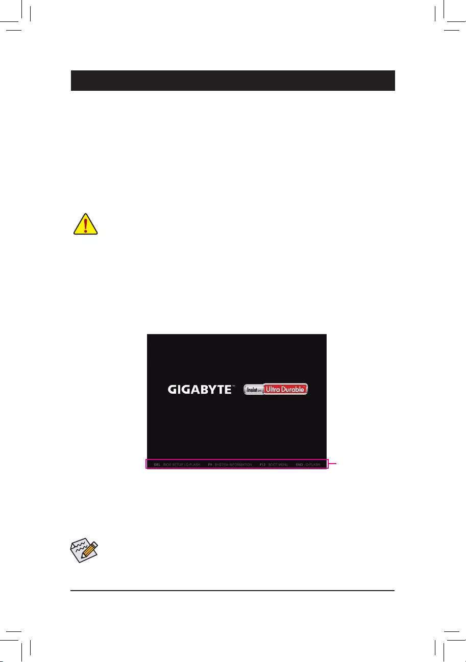
2-1 Startup Screen
The following startup Logo screen will appear when the computer boots.
•When the system is not stable as usual, select the Load Optimized Defaults item to set your system to its defaults.
•The BIOS Setup menus described in this chapter are for reference only and may differ by BIOS version.
Function Keys
There are two different BIOS modes as follows and you can use the <F2> key to switch between the two modes.
The Classic Setup mode provides detailed BIOS settings. You can press the arrow keys on your keyboard to
move among the items and press <Enter> to accept or enter a sub-menu. Or you can use your mouse to select
the item you want.
Easy Mode allows users to quickly view their current system information or to make adjustments for optimum
performance.InEasyMode,youcanuseyourmousetomovethroughcongurationitems.
— 19 —
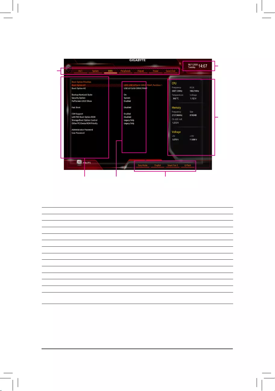
2-2 The Main Menu
Hardware
Information
CongurationItems Current Settings
Setup
Menus
System Time
Quick Access Bar allows you to enter Easy Mode, select
BIOSdefaultlanguage,congurefansettings,orenter
Q-Flash.
Classic Setup Function Keys
<f><g>Move the selection bar to select a setup menu
<h><i>Movetheselectionbartoselectancongurationitemonamenu
<Enter> Execute command or enter a menu
<+>/<Page Up> Increase the numeric value or make changes
<->/<Page Down> Decrease the numeric value or make changes
<F1> Show descriptions of the function keys
<F2> Switch to Easy Mode
<F5> RestorethepreviousBIOSsettingsforthecurrentsubmenus
<F7> LoadtheOptimizedBIOSdefaultsettingsforthecurrentsubmenus
<F8> Access the Q-Flash utility
<F9> Display system information
<F10> Save all the changes and exit the BIOS Setup program
<F12> Capture the current screen as an image and save it to your USB drive
<Esc> Main Menu: Exit the BIOS Setup program
Submenus: Exit current submenu
— 20 —
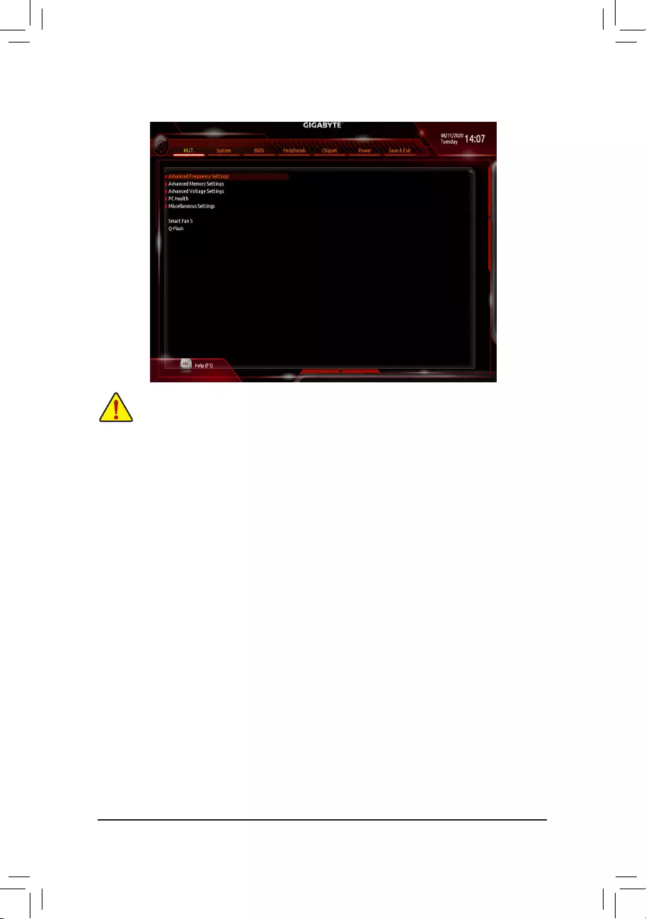
2-3 M.I.T.
Whether the system will work stably with the overclock/overvoltage settings you made is dependent on your overall
systemcongurations.Incorrectlydoingoverclock/overvoltagemayresultindamagetoCPU,chipset,ormemory
and reduce the useful life of these components. This page is for advanced users only and we recommend you not to
alter the default settings to prevent system instability or other unexpected results. (Inadequately altering the settings
may result in system’s failure to boot. If this occurs, clear the CMOS values and reset the board to default values.)
Advanced Frequency Settings
&CPU Clock Control
AllowsyoutomanuallysettheCPUbaseclockin1MHzincrements.(Default:Auto)
Important: It is highly recommended that the CPU frequency be set in accordance with the CPU
specications.
&Host Clock Value
Displays the current operating Host Clock frequency.
&GFX Clock Frequency (Note)
Allows you to alter the frequency for the GPU. After you alter the GFX Clock Frequency settings, make
sure to adjust the GFX Core Voltage settings. (Default: Auto)
NOTE:TheadjustablerangeisdependentontheCPUbeinginstalled.Auto lets the BIOS automatically
congurethissetting.
&GFX Core Voltage (Note)
Allows you to alter the voltage for the GPU. (Default: Auto)
NOTE:TheadjustablerangeisdependentontheCPUbeinginstalledAuto lets the BIOS automatically
congurethissetting.
&CPU Clock Ratio
Allows you to alter the clock ratio for the installed CPU. The adjustable range is dependent on the CPU
being installed.
&CPU Frequency
Displays the current operating CPU frequency.
(Note) ThisitemispresentonlywhenyouinstallaCPUthatsupportsthisfeature.
— 21 —

(Note1) ThisitemispresentonlywhenyouinstallaCPUthatsupportsthisfeature.
(Note2) ThisitemispresentonlywhenyouinstallaCPUandamemorymodulethatsupportthisfeature.
Advanced CPU Core Settings
&CPU Clock Ratio, CPU Frequency
The settings above are synchronous to those under the same items on the Advanced Frequency Settings
menu.
&Core Performance Boost
Allows you to determine whether to enable the Core Performance Boost (CPB) technology, a CPU
performance-boost technology. (Default: Auto)
&AMD Cool&Quiet function
Enabled Lets the AMD Cool’n’Quiet driver dynamically adjust the CPU clock and VID to reduce
heat output from your computer and its power consumption. (Default)
Disabled Disables this function.
&SVM Mode
VirtualizationenhancedbyVirtualizationTechnologywillallowaplatformtorunmultipleoperatingsystems
andapplicationsinindependentpartitions.Withvirtualization,onecomputersystemcanfunctionasmultiple
virtual systems. (Default: Disabled)
&PPC Adjustment (Note 1)
AllowsyoutoxthePStateoftheCPU.(Default:PState0)
&Global C-state Control
Allows you to determine whether to let the CPU enter C states. When enabled, the CPU core frequency
will be reduced during system halt state to decrease power consumption. (Default: Enabled)
&Power Supply Idle Control
Enables or disables Package C6 State.
Typical Current Idle Disables this function.
Low Current Idle Enables this function.
Auto LetstheBIOSautomaticallycongurethissetting. (Default)
&CCD Control (Note 1)
Sets the number of CCDs to be used. (Default: Auto)
&CPPC (Note 1)
Enables or disables the CPPC feature. (Default: Auto)
&CPPC Preferred Cores (Note 1)
Enables or disables the CPPC Preferred Cores feature. (Default: Auto)
&Opcache Control (Note 1)
Enables or disables Opcache. AutoletstheBIOSautomaticallycongurethissetting.(Default:Auto)
&Downcore Control
Allows you to select the number of CPU cores to enable (the number of CPU cores may vary by CPU).
AutoletstheBIOSautomaticallycongurethissetting.(Default:Auto)
&SMT Mode
Allows you to enable or disable the CPU Simultaneous Multi-Threading technology. This feature only works
for operating systems that support multi-processor mode. AutoletstheBIOSautomaticallycongurethis
setting. (Default: Auto)
&ExtremeMemoryProle(X.M.P.)(Note 2)
Allows the BIOS to read the SPD data on XMP memory module(s) to enhance memory performance when
enabled.
Disabled Disables this function. (Default)
Prole1 UsesProle1settings.
Prole2(Note2) UsesProle2settings.
— 22 —

&System Memory Multiplier
Allows you to set the system memory multiplier. Auto sets memory multiplier according to memory SPD
data. (Default: Auto)
&Memory Frequency (MHz)
Therstmemoryfrequencyvalueisthenormaloperatingfrequencyofthememorybeingused;thesecond
is the memory frequency that is automatically adjusted according to the System Memory Multiplier settings.
Advanced Memory Settings
&
ExtremeMemoryProle(X.M.P.)
(Note)
, System Memory Multiplier, Memory Frequency(Mhz)
The settings above are synchronous to those under the same items on the Advanced Frequency Settings
menu.
&XMP High Frequency Support (Note)
Allowsyoutoselectthecompatibilitylevelforhigh-frequencymemory.Thisitemiscongurableonlywhen
ExtremeMemoryProle(X.M.P.) is set to Prole1 or Prole2. (Default: Auto)
&Memory Timing Mode
Manualallowsthememorytimingsettingsbelowtobecongurable.Optionsare:Auto(default),Manual.
&ProleDDRVoltage
When using a non-XMP memory module or ExtremeMemoryProle(X.M.P.) is set to Disabled, the value
isdisplayedaccordingtoyourmemoryspecication.WhenExtremeMemoryProle(X.M.P.) is set to
Prole1 or Prole2, the value is displayed according to the SPD data on the XMP memory.
d Standard Timing Control, Advanced Timing Control, CAD Bus Setup Timing, CAD Bus
DriveStrength,DataBusConguration
Thesesectionsprovidememorytimingsettings.Therespectivetimingsettingscreensarecongurable
only when Memory Timing Mode is set to Manual.Note:Yoursystemmaybecomeunstableorfailtoboot
after you make changes on the memory timings. If this occurs, please reset the board to default values by
loadingoptimizeddefaultsorclearingtheCMOSvalues.
Advanced Voltage Settings
This sub-menu allows you to set CPU, chipset and memory voltages.
PC Health Status
&Reset Case Open Status
Disabled Keeps or clears the record of previous chassis intrusion status. (Default)
Enabled Clears the record of previous chassis intrusion status and the Case Openeldwill
show»No»atnextboot.
&Case Open
Displays the detection status of the chassis intrusion detection device attached to the motherboard CI
header.Ifthesystemchassiscoverisremoved,thiseldwillshow«Yes»,otherwiseitwillshow«No».To
clear the chassis intrusion status record, set Reset Case Open Status to Enabled, save the settings to
the CMOS, and then restart your system.
& CPU Vcore/CPU VDDP/DRAM Channel A/B Voltage/+3.3V/+5V/+12V/VCORE SOC
Displays the current system voltages.
(Note) ThisitemispresentonlywhenyouinstallaCPUandamemorymodulethatsupportthisfeature.
— 23 —

Miscellaneous Settings
&PCIeSlotConguration
Allows you to set the operation mode of the PCI Express slots to Gen 1, Gen 2, or Gen 3. Actual operation
modeissubjecttothehardwarespecicationofeachslot.AutoletstheBIOSautomaticallycongurethis
setting. (Default: Auto)
&3DMark01 Enhancement
Allows you to determine whether to enhance some legacy benchmark performance. (Default: Disabled)
`Smart Fan 5
&Monitor
Allowsyoutoselectatargettomonitorandtomakefurtheradjustment.(Default:CPUFAN)
&Fan Speed Control
Allows you to determine whether to enable the fan speed control function and adjust the fan speed.
Normal Allowsthefantorunatdifferentspeedsaccordingtothetemperature.Youcanadjust
the fan speed with System Information Viewer based on your system requirements.
(Default)
Silent Allows the fan to run at slow speeds.
Manual Allows you to control the fan speed in the curve graph.
Full Speed Allows the fan to run at full speeds.
&Fan Control Use Temperature Input
Allows you to select the reference temperature for fan speed control.
&Temperature Interval
Allows you to select the temperature interval for fan speed change.
&Fan Control Mode
Auto Lets the BIOS automatically detect the type of fan installed and sets the optimal control
mode. (Default)
Voltage Voltage mode is recommended for a 3-pin fan.
PWM PWM mode is recommended for a 4-pin fan.
&Fan Stop
Enables or disables the fan stop function. You can set the temperature limit using the temperature curve.
The fan stops operation when the temperature is lower than the limit. (Default: Disabled)
&Temperature
Displays the current temperature of the selected target area.
&Fan Speed
Displays current fan speeds.
&Temperature Warning
Sets the warning threshold for temperature. When temperature exceeds the threshold, BIOS will emit
warning sound. Options are: Disabled (default), 60oC/140oF, 70oC/158oF, 80oC/176oF, 90oC/194oF.
&Fan Fail Warning
Allows the system to emit warning sound if the fan is not connected or fails. Check the fan condition or fan
connection when this occurs. (Default: Disabled)
`Q-Flash
AllowsyoutoaccesstheQ-FlashutilitytoupdatetheBIOSorbackupthecurrentBIOSconguration.
— 24 —
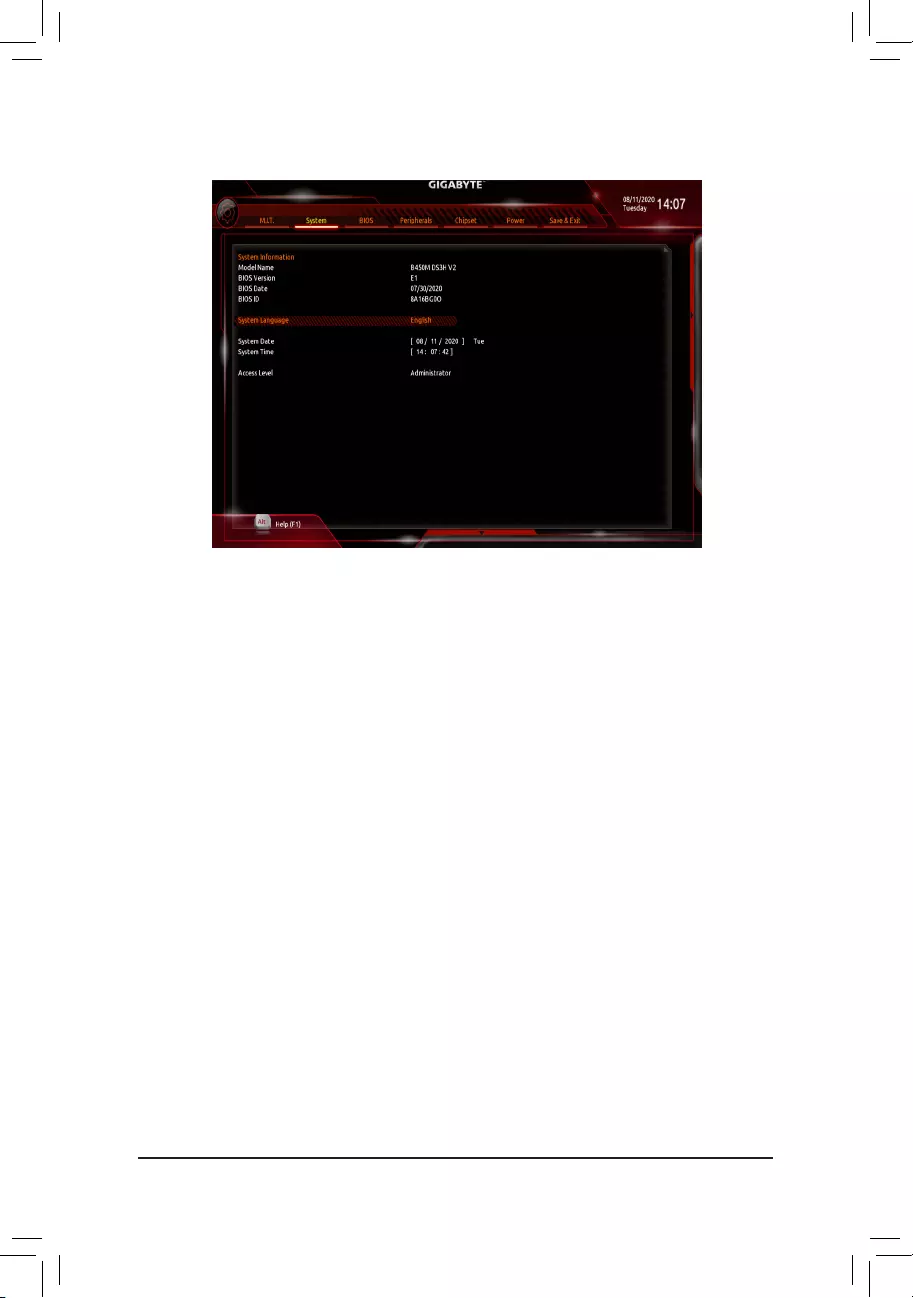
2-4 System
This section provides information on your motherboard model and BIOS version. You can also select the default
language used by the BIOS and manually set the system time.
&System Language
Selects the default language used by the BIOS.
&System Date
Sets the system date. The date format is week (read-only), month, date, and year. Use <Enter> to switch
betweentheMonth,Date,andYeareldsandusethe<PageUp>or<PageDown>keytosetthedesired
value.
&System Time
Sets the system time. The time format is hour, minute, and second. For example, 1 p.m. is 13:00:00. Use
<Enter>toswitchbetweentheHour,Minute,andSecondeldsandusethe<PageUp>or<PageDown>
key to set the desired value.
&Access Level
Displays the current access level depending on the type of password protection used. (If no password is
set, the default will display as Administrator.) The Administrator level allows you to make changes to all
BIOS settings; the User level only allows you to make changes to certain BIOS settings but not all.
— 25 —
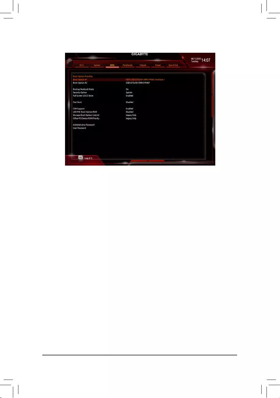
&Boot Option Priorities
Speciestheoverallbootorderfromtheavailabledevices.RemovablestoragedevicesthatsupportGPT
formatwillbeprexedwith«UEFI:»stringonthebootdevicelist.Tobootfromanoperatingsystemthat
supportsGPTpartitioning,selectthedeviceprexedwith»UEFI:»string.
Or if you want to install an operating system that supports GPT partitioning such as Windows 10 64-bit,
selecttheopticaldrivethatcontainstheWindows1064-bitinstallationdiscandisprexedwith«UEFI:»
string.
&Hard Drive/CD/DVD ROM Drive/Floppy Drive/Network Device BBS Priorities
Speciesthebootorderforaspecicdevicetype,suchasharddrives,opticaldrives,oppydiscdrives,
anddevicesthatsupportBootfromLANfunction,etc.Press<Enter>onthisitemtoenterthesubmenuthat
presents the devices of the same type that are connected. This item is present only if at least one device
for this type is installed.
&Bootup NumLock State
EnablesordisablesNumlockfeatureonthenumerickeypadofthekeyboardafterthePOST.(Default:On)
&Security Option
Specieswhetherapasswordisrequiredeverytimethesystemboots,oronlywhenyouenterBIOSSetup.
Afterconguringthisitem,setthepassword(s)undertheAdministrator Password/User Password item.
Setup A password is only required for entering the BIOS Setup program.
System A password is required for booting the system and for entering the BIOS Setup
program. (Default)
&Full Screen LOGO Show
Allows you to determine whether to display the GIGABYTE Logo at system startup. Disabled skips the
GIGABYTE Logo when the system starts up. (Default: Enabled)
&Fast Boot
Enables or disables Fast Boot to shorten the OS boot process. Ultra Fast provides the fastest bootup
speed. (Default: Disabled)
2-5 BIOS
— 26 —

&SATA Support
All Sata Devices All SATA devices are functional in the operating system and during the POST.
Last Boot HDD Only Except for the previous boot drive, all SATA devices are disabled before the OS
boot process completes. (Default)
ThisitemiscongurableonlywhenFast Boot is set to Enabled or Ultra Fast.
&NVMe Support
AllowsyoutoenableordisableNVMedevice(s).(Default:Enabled)
ThisitemiscongurableonlywhenFast Boot is set to Enabled or Ultra Fast.
&VGA Support
Allows you to select which type of operating system to boot.
Auto EnableslegacyoptionROMonly.
EFIDriver EnablesEFIoptionROM.(Default)
ThisitemiscongurableonlywhenFast Boot is set to Enabled or Ultra Fast.
&USB Support
Disabled All USB devices are disabled before the OS boot process completes.
Full Initial All USB devices are functional in the operating system and during the POST.
(Default)
Partial Initial Part of the USB devices are disabled before the OS boot process completes.
ThisitemiscongurableonlywhenFast Boot is set to Enabled. This function is disabled when Fast Boot
is set to Ultra Fast.
&PS2 Devices Support
Disabled All PS/2 devices are disabled before the OS boot process completes.
Enabled All PS/2 devices are functional in the operating system and during the POST.
(Default)
ThisitemiscongurableonlywhenFast Boot is set to Enabled. This function is disabled when Fast Boot
is set to Ultra Fast.
&NetWork Stack Driver Support
Disabled Disables booting from the network. (Default)
Enabled Enables booting from the network.
ThisitemiscongurableonlywhenFast Boot is set to Enabled or Ultra Fast.
&CSM Support
Enables or disables UEFI CSM (Compatibility Support Module) to support a legacy PC boot process.
Enabled Enables UEFI CSM. (Default)
Disabled Disables UEFI CSM and supports UEFI BIOS boot process only.
&LAN PXE Boot Option ROM
AllowsyoutoselectwhethertoenablethelegacyoptionROMfortheLANcontroller.(Default:Disabled)
ThisitemiscongurableonlywhenCSM Support is set to Enabled.
&Storage Boot Option Control
AllowsyoutoselectwhethertoenabletheUEFIorlegacyoptionROMforthestoragedevicecontroller.
Disabled DisablesoptionROM.
UEFIOnly EnablesUEFIoptionROMonly.
LegacyOnly EnableslegacyoptionROMonly.(Default)
ThisitemiscongurableonlywhenCSM Support is set to Enabled.
&Other PCI Device ROM Priority
AllowsyoutoselectwhethertoenabletheUEFIorLegacyoptionROMforthePCIdevicecontrollerother
thantheLAN,storagedevice,andgraphicscontrollers.
Disabled DisablesoptionROM.
UEFIOnly EnablesUEFIoptionROMonly.(Default)
LegacyOnly EnableslegacyoptionROMonly.
ThisitemiscongurableonlywhenCSM Support is set to Enabled.
— 27 —

&Administrator Password
Allowsyoutocongureanadministratorpassword.Press<Enter>onthisitem,typethepassword,and
thenpress<Enter>.Youwillberequestedtoconrmthepassword.Typethepasswordagainandpress
<Enter>. You must enter the administrator password (or user password) at system startup and when entering
BIOS Setup. Differing from the user password, the administrator password allows you to make changes to
all BIOS settings.
&User Password
Allowsyoutocongureauserpassword.Press<Enter>onthisitem,typethepassword,andthenpress
<Enter>.Youwillberequestedtoconrmthepassword.Typethepasswordagainandpress<Enter>.
You must enter the administrator password (or user password) at system startup and when entering BIOS
Setup. However, the user password only allows you to make changes to certain BIOS settings but not all.
To cancel the password, press <Enter> on the password item and when requested for the password, enter
thecorrectonerst.Whenpromptedforanewpassword,press<Enter>withoutenteringanypassword.
Press<Enter>againwhenpromptedtoconrm.
NOTE:BeforesettingtheUserPassword,besuretosettheAdministratorPasswordrst.
Secure Boot
AllowsyoutoenableordisableSecureBootandcongurerelatedsettings.Thisitemiscongurableonly
when CSM Support is set to Disabled.
— 28 —
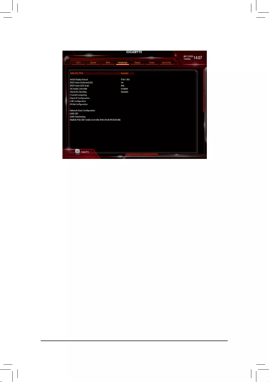
2-6 Peripherals
&AMD CPU fTPM
Enables or disables the TPM 2.0 function integrated in the AMD CPU. (Default: Disabled)
&Initial Display Output
(Note)
SpeciestherstinitiationofthemonitordisplayfromtheinstalledPCIExpressgraphicscardortheonboard
graphics.
IGDVideo Setstheonboardgraphicsastherstdisplay.
PCIe1Slot SetsthegraphicscardonthePCIEX16slotastherstdisplay.(Default)
&RGB Fusion (Onboard LED)
Allows you to set the LED lighting mode for the motherboard.
On Enables this function. (Default)
Off Disables this function.
Pulse Mode All LEDs simultaneously fade in and fade out.
&RGB Fusion (LED strip)
Allows you to set the display color of the external LED strip.
&HD Audio Controller
Enables or disables the onboard audio function. (Default: Enabled)
If you wish to install a 3rd party add-in audio card instead of using the onboard audio, set this item to
Disabled.
&Above 4G Decoding
Enables or disables 64-bit capable devices to be decoded in above 4 GB address space (only if your system
supports 64-bit PCI decoding). Set to Enabled if more than one advanced graphics card are installed and
their drivers are not able to be launched when entering the operating system (because of the limited 4 GB
memory address space). (Default: Disabled)
Trusted Computing
Enables or disables Trusted Platform Module (TPM).
(Note) ThisitemispresentonlywhenyouinstallaCPUthatsupportsthisfeature.
— 29 —

SuperIOConguration
&Serial Port 1
Enables or disables the onboard serial port. (Default: Enabled)
USBConguration
&Legacy USB Support
Allows USB keyboard/mouse to be used in MS-DOS. (Default: Enabled)
&XHCI Hand-off
Determines whether to enable XHCI Hand-off feature for an operating system without XHCI Hand-off
support. (Default: Enabled)
&USB Mass Storage Driver Support
Enables or disables support for USB storage devices. (Default: Enabled)
&Mass Storage Devices
Displays a list of connected USB mass storage devices. This item appears only when a USB storage device
is installed.
&Port 60/64 Emulation
Enables or disables emulation of I/O ports 64h and 60h. This should be enabled for full legacy support
for USB keyboards/mice in MS-DOS or in operating system that does not natively support USB devices.
(Default: Disabled)
NVMeConguration
DisplaysinformationonyourM.2NVMEPCIeSSDifinstalled.
NetworkStackConguration
&Network Stack
Disables or enables booting from the network to install a GPT format OS, such as installing the OS from
the Windows Deployment Services server. (Default: Disabled)
&Ipv4 PXE Support
EnablesordisablesIPv4PXESupport.ThisitemiscongurableonlywhenNetwork Stack is enabled.
&Ipv4 HTTP Support
EnablesordisablesHTTPbootsupportforIPv4.ThisitemiscongurableonlywhenNetwork Stack is
enabled.
&Ipv6 PXE Support
EnablesordisablesIPv6PXESupport.ThisitemiscongurableonlywhenNetwork Stack is enabled.
&Ipv6 HTTP Support
EnablesordisablesHTTPbootsupportforIPv6.ThisitemiscongurableonlywhenNetwork Stack is
enabled.
&IPSECCerticate
Enablesordisables Internet Protocol Security.Thisitem is congurable onlywhen Network Stack is
enabled.
&PXE boot wait time
Allowsyoutocongurehowlongtowaitbeforeyoucanpress<Esc>toabortthePXEboot.Thisitemis
congurableonlywhenNetwork Stack is enabled. (Default: 0)
&Media detect count
Allowsyoutosetthenumberoftimestocheckthepresenceofmedia.Thisitemiscongurableonlywhen
Network Stack is enabled. (Default: 1)
— 30 —

AMD CBS
Thissub-menuprovidesAMDCBS-relatedcongurationoptions.
Realtek PCIe GBE Family Controller
Thissub-menuprovidesinformationonLANcongurationandrelatedcongurationoptions.
— 31 —
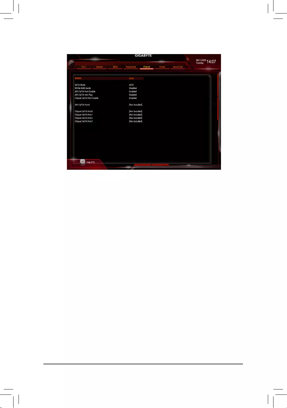
2-7 Chipset
(Note) ThisitemispresentonlywhenyouinstallaCPUthatsupportsthisfeature.
&IOMMU
Enables or disables AMD IOMMU support. (Default: Auto)
&Integrated Graphics (Note)
Enables or disables the onboard graphics function.
Auto The BIOS will automatically enable or disable the onboard graphics depending on the
graphics card being installed. (Default)
Forces Enables the onboard graphics.
Disabled Disables the onboard graphics.
&UMA Mode (Note)
Specify the UMA mode.
Auto LetstheBIOSautomaticallycongurethissetting. (Default)
UMASpecied SetstheUMAFrameBufferSize.
UMA Auto Sets the display resolution.
ThisitemiscongurableonlywhenIntegrated Graphics is set to Forces.
&UMA Frame Buffer Size (Note)
Framebuffersizeisthetotalamountofsystemmemoryallocatedsolelyfortheonboardgraphicscontroller.
MS-DOS, for example, will use only this memory for display. Options are: Auto (default), 64M~16G.
ThisitemiscongurableonlywhenUMA Mode is set to UMASpecied.
&Display Resolution (Note)
Allows you to set the display resolution. Options are: Auto (default), 1920×1080 and below, 2560×1600,
3840×2160.
ThisitemiscongurableonlywhenUMA Mode is set to UMA Auto.
— 32 —

&SATA Mode
EnablesordisablesRAIDfortheintegratedSATAcontrollersorcongurestheSATAcontrollerstoAHCI
mode.
RAID EnablesRAIDfortheSATAcontroller.
AHCI CongurestheSATAcontrollerstoAHCImode.AdvancedHostControllerInterface
(AHCI)isaninterfacespecicationthatallowsthestoragedrivertoenableadvanced
SerialATAfeaturessuchasNativeCommandQueuingandhotplug.(Default)
&NVMe RAID mode (M2A_SOCKET Connector)
AllowsyoutodeterminewhethertouseyourM.2NVMePCIeSSDstocongureRAID.(Default:Disabled)
&APU SATA Port Enable (M2A_SOCKET Connector)
EnablesordisablestheM.2NVMePCIeSSDscontroller.(Default:Enabled)
&APU SATA Hot plug
Enables or disable the hot plug capability for M2A_SOCKET Connector. (Default: Disabled)
&Chipset SATA Port Enable (SATA3 0, 1, 2, 3 Connectors)
Enables or disables the integrated SATA controllers. (Default: Enabled)
&APU SATA Port 0 (M2A_SOCKET Connector)
Displays the information of the connected M.2 SATA device.
&Chipset SATA Port 0/1/2/3 (SATA3 0, 1, 2, 3 Connectors)
Displays the information of the connected SATA device(s).
— 33 —
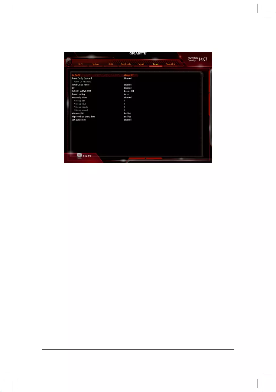
&AC BACK
Determines the state of the system after the return of power from an AC power loss.
Memory The system returns to its last known awake state upon the return of the AC power.
Always On The system is turned on upon the return of the AC power.
Always Off The system stays off upon the return of the AC power. (Default)
&Power On By Keyboard
Allows the system to be turned on by a PS/2 keyboard wake-up event.
Note:Tousethisfunction,youneedanATXpowersupplyprovidingatleast1Aonthe+5VSBlead.
Disabled Disables this function. (Default)
Password Set a password with 1~5 characters to turn on the system.
Keyboard98 PressPOWERbuttonontheWindows98keyboardtoturnonthesystem.
Any key Press any key to turn on the system.
&Power On Password
Set the password when Power On By Keyboard is set to Password.
Press <Enter> on this item and set a password with up to 5 characters and then press <Enter> to accept.
To turn on the system, enter the password and press <Enter>.
Note:Tocancelthepassword,press<Enter>onthisitem.Whenpromptedforthepassword,press<Enter>
again without entering the password to clear the password settings.
&Power On By Mouse
Allows the system to be turned on by a PS/2 mouse wake-up event.
Note:Tousethisfunction,youneedanATXpowersupplyprovidingatleast1Aonthe+5VSBlead.
Disabled Disables this function. (Default)
Move Move the mouse to turn on the system.
Double Click Double click on left button on the mouse to turn on the system.
2-8 Power
— 34 —

&ErP
DetermineswhethertoletthesystemconsumeleastpowerinS5(shutdown)state.Note:Whenthisitem
is set to Enabled,thefollowingfunctionswillbecomeunavailable:ResumebyAlarm,poweronbymouse,
and power on by keyboard.
&Soft-Off by PWR-BTTN
ConguresthewaytoturnoffthecomputerinMS-DOSmodeusingthepowerbutton.
Instant-Off Press the power button and then the system will be turned off instantly. (Default)
Delay 4 Sec. Press and hold the power button for 4 seconds to turn off the system. If the power
button is pressed for less than 4 seconds, the system will enter suspend mode.
&Power Loading
Enables or disables dummy load. When the power supply is at low load, a self-protection will activate causing
it to shutdown or fail. If this occurs, please set to Enabled. AutoletstheBIOSautomaticallycongurethis
setting. (Default: Auto)
&Resume by Alarm
Determines whether to power on the system at a desired time. (Default: Disabled)
If enabled, set the date and time as following:
Wakeupday:Turnonthesystemataspecictimeoneachdayoronaspecicdayinamonth.
Wake up hour/minute/second: Set the time at which the system will be powered on automatically.
Note:Whenusingthisfunction,avoidinadequateshutdownfromtheoperatingsystemorremovalofthe
AC power, or the settings may not be effective.
&Wake on LAN
EnablesordisablesthewakeonLANfunction.(Default:Enabled)
&High Precision Event Timer
Enables or disables High Precision Event Timer (HPET) in the operating system. (Default: Enabled)
&CEC 2019 Ready
Allows you to select whether to allow the system to adjust power consumption when it is in shutdown, idle,
or standby state in order to comply with the CEC (California Energy Commission) 2019 Standards. (Default:
Disabled)
— 35 —
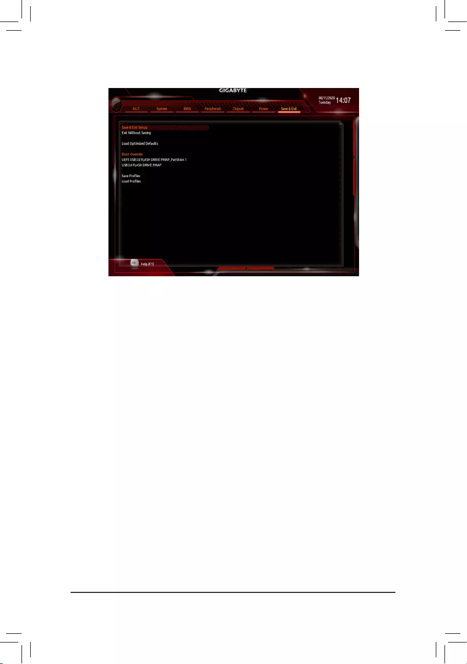
2-9 Save & Exit
&Save & Exit Setup
Press <Enter> on this item and select Yes. This saves the changes to the CMOS and exits the BIOS Setup
program. Select No or press <Esc> to return to the BIOS Setup Main Menu.
&Exit Without Saving
Press <Enter> on this item and select Yes. This exits the BIOS Setup without saving the changes made
in BIOS Setup to the CMOS. Select No or press <Esc> to return to the BIOS Setup Main Menu.
&Load Optimized Defaults
Press <Enter> on this item and select Yes to load the optimal BIOS default settings. The BIOS defaults
settingshelpthesystemtooperateinoptimumstate.AlwaysloadtheOptimizeddefaultsafterupdating
the BIOS or after clearing the CMOS values.
&Boot Override
Allows you to select a device to boot immediately. Press <Enter> on the device you select and select Yes
toconrm.Yoursystemwillrestartautomaticallyandbootfromthatdevice.
&SaveProles
ThisfunctionallowsyoutosavethecurrentBIOSsettingstoaprole.Youcancreateupto8prolesand
saveasSetupProle1~SetupProle8.Press<Enter>tocomplete.OryoucanselectSelect File in
HDD/FDD/USBtosavetheproletoyourstoragedevice.
&LoadProles
If your system becomes unstable and you have loaded the BIOS default settings, you can use this function
toloadtheBIOSsettingsfromaprolecreatedbefore, withoutthehasslesofreconguringtheBIOS
settings.Firstselecttheproleyouwishtoloadandthenpress<Enter>tocomplete.YoucanselectSelect
File in HDD/FDD/USBtoinputtheprolepreviouslycreatedfromyourstoragedeviceorloadtheprole
automatically created by the BIOS, such as reverting the BIOS settings to the last settings that worked
properly (last known good record).
— 36 —
Chapter 3 Appendix
3-1 ConguringaRAIDSet
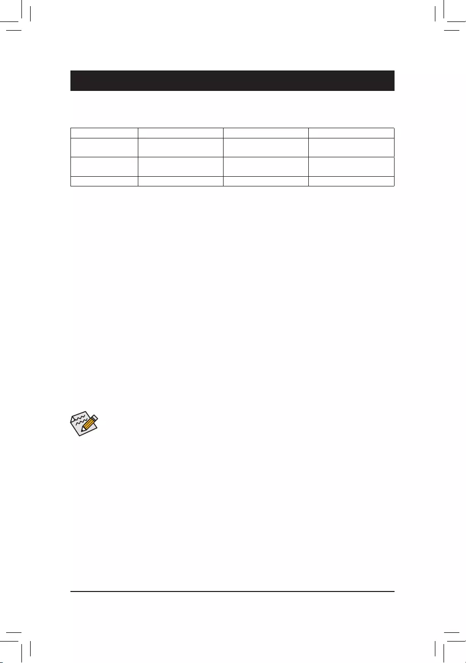
RAID Levels
Before you begin, please prepare the following items:
•At least two SATA hard drives or SSDs (To ensure optimal performance, it is recommended that you use two
hard drives with identical model and capacity). (Note)
•Windows setup disc.
•Motherboard driver disc.
•A USB thumb drive.
ConguringtheOnboardSATAController
A. Installing SATA hard drive(s) in your computer
Install the hard drives/SSDs in the SATA/M.2 connectors on the motherboard. Then connect the power connectors
from your power supply to the hard drives.
B.ConguringSATAcontrollermodeinBIOSSetup
MakesuretoconguretheSATAcontrollermodecorrectlyinsystemBIOSSetup.
Steps:
1. Turn on your computer and press <Delete> to enter BIOS Setup during the POST (Power-On Self-Test).
Under Chipset, ensure Chipset SATA Port Enable is enabled. Set SATA Mode to RAID. Then save the
settingsandrestartyourcomputer.(IfyouwanttouseNVMePCIeSSDstocongureRAID,makesureto
set NVMe RAID mode to Enabled.)
2. IfyouwanttocongureUEFIRAID,followthestepsin«C-1.»ToenterthelegacyRAIDROM,savethe
settingsandexitBIOSSetup.Referto»C-2″formoreinformation.
The BIOS Setup menus described in this section may differ from the exact settings for your motherboard.
The actual BIOS Setup menu options you will see shall depend on the motherboard you have and
the BIOS version.
C-1.UEFIRAIDConguration
Steps:
1. In BIOS Setup, go to BIOS and set CSM Support to Disabled. Save the changes and exit BIOS Setup.
2. After the system reboot, enter BIOS Setup again. Then enter the Peripherals\RAIDXpert2Conguration
Utility sub-menu.
3. On the RAIDXpert2CongurationUtility screen, press <Enter> on Array Management to enter the Create
Array screen. Then, select a RAID level.RAIDlevelssupportedincludeRAID0(Stripe),RAID1(Mirror),
andRAID10(theselectionsavailabledependonthenumberoftheharddrivesbeinginstalled).Next,press
<Enter> on Select Physical Disks to enter the Select Physical Disks screen.
4. On the Select Physical Disksscreen,selecttheharddrivestobeincludedintheRAIDarrayandsetthem
to Enabled.Next,usethedownarrowkeytomovetoApply Changes and press <Enter>. Then return to
the previous screen and set the Array Size, Array Size Unit, Read Cache Policy and Write Cache Policy.
RAID 0 RAID 1 RAID 10
MinimumNumberof
Hard Drives ≥2 2 4
Array Capacity Numberofharddrives*
Sizeofthesmallestdrive
Sizeofthesmallestdrive (Numberofharddrives/2)*
Sizeofthesmallestdrive
Fault Tolerance No Yes Yes
(Note) AnM.2PCIeSSDcannotbeusedtosetupaRAIDseteitherwithanM.2SATASSDoraSATAharddrive.
— 37 —

C-2.ConguringLegacyRAIDROM
EnterthelegacyRAIDBIOSsetuputilitytocongureaRAIDarray.Skipthisstepandproceedwiththeinstallation
ofWindowsoperatingsystemforanon-RAIDconguration.
Steps:
1. After the POST memory test begins and before the operating system boot begins, look for a message which
says«Press<Ctrl-F>toenterRAIDOptionROMUtility».Press<Ctrl>+<R>toentertheRAIDBIOSsetuputility.
2. To create a new array, press <Enter> on the Create Array option.
3. The selection bar will move to the Disks section on the right of the screen. Select the hard drives to be
includedintheRAIDarray.Usetheupordownarrowkeytoselectaharddriveandpress<Insert>.The
selected hard drive will be shown in green. To use all of the hard drives, simply press <A> to select all. Then
press <Enter> and the selection bar will move to the User Input section on the left bottom of the screen.
4. First,selectaRAIDmodeandpress<Enter>.Theselectionsavailabledependonthenumberoftheharddrives
beinginstalled.Thenfollowtheon-screeninstructionstospecifythearraysize.YoucanselectAll available
spacetousethemaximumsizeallowedorusetheupordownarrowkeytoadjustthesizeandpress<Enter>.
5. Selectacachingmode.OptionsincludeRead/Write,ReadOnly,andNone.Thenpress<Enter>toproceed.
6. Finally,amessagewhichsays«ConrmCreationofArray»willappear.Press<C>toconrmor<Esc>to
return to the previous screen.
7. Whencompleted,youwillseethenewarrayonthemainscreen.ToexittheRAIDBIOSutility,press<Esc>
andthenpress<C>toconrm.
Installing the SATA RAID Driver and Operating System
With the correct BIOS settings, you are ready to install the operating system.
Installing the Operating System
AssomeoperatingsystemsalreadyincludeRAIDdriver,youdonotneedtoinstallseparateRAIDdriverduring
the Windows installation process. After the operating system is installed, we recommend that you install all
requireddriversfromthemotherboarddriverdiscusing«XpressInstall»toensuresystemperformanceand
compatibility.IftheoperatingsystemtobeinstalledrequiresthatyouprovideadditionalRAIDdriverduringthe
OS installation process, please refer to the steps below:
1. Copy the Hw10 folder under the \Boot folder in the driver disc to your USB thumb drive.
2. Boot from the Windows setup disc and perform standard OS installation steps. When the screen requesting
you to load the driver appears, select Browse.
3. Insert the USB thumb drive and then browse to the location of the driver. The location of the drivers is as
follows:
\Hw10\RAID\x64
4. Select AMD-RAID Bottom DevicerstandclickNext to load the driver. Then select AMD-RAID Controller
and click Next to load the driver. Finally, continue the OS installation.
PleasevisitGIGABYTE’swebsitefordetailsonconguringaRAIDarray.
5. After setting the capacity, move to Create Array and press <Enter> to begin.
6. After completing, you’ll be brought back to the Array Management screen. Under Manage Array Properties
youcanseethenewRAIDvolumeandinformationonRAIDlevel,arrayname,arraycapacity,etc.
— 38 —
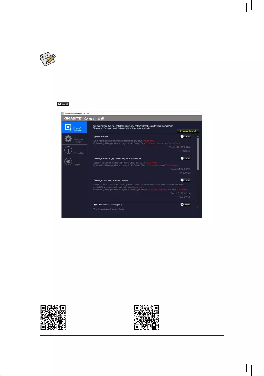
•Beforeinstallingthedrivers,rstinstalltheoperatingsystem.
•After installing the operating system, insert the motherboard driver disc into your optical drive. Click
onthemessage»Taptochoosewhathappenswiththisdisc»onthetop-rightcornerofthescreen
andselect»RunRun.exe.»(OrgotoMyComputer,double-clicktheopticaldriveandexecutethe
Run.exeprogram.)
3-2 Drivers Installation
«XpressInstall»willautomaticallyscanyoursystemandthenlistallofthedriversthatarerecommendedto
install. You can click the Xpress Installbuttonand«XpressInstall»willinstallalloftheselecteddrivers.Orclick
the arrow icon to individually install the drivers you need.
Please visit GIGABYTE’s website for
more software information.
Please visit GIGABYTE’s website for
more troubleshooting information.
— 39 —
Regulatory Notices
United States of America, Federal Communications Commission Statement
This equipment has been tested and found to comply with the limits for a
ClassBdigitaldevice,pursuanttoPart15oftheFCCRules.Theselimits
are designed to provide reasonable protection against harmful interference
in a residential installation. This equipment generates, uses and can radiate
radio frequency energy and, if not installed and used in accordance with
manufacturer’s instructions, may cause harmful interference to radio
communications. However, there is no guarantee that interference will
not occur in a particular installation. If this equipment does cause harmful
interference to radio or television reception, which can be determined by
turning the equipment off and on, the user is encouraged to try to correct
the interference by one or more of the following measures:
•Reorientorrelocatethereceivingantenna.
•Increase the separation between the equipment and receiver.
•Connect the equipment to an outlet on a circuit different from that to
which the receiver is connected.
•Consult the dealer or an experienced radio/TV technician for help.
Canadian Department of Communications Statement
This digital apparatus does not exceed the Class B limits for radio
noiseemissionsfromdigitalapparatussetoutintheRadioInterference
RegulationsoftheCanadianDepartmentofCommunications.Thisclass
B digital apparatus complies with Canadian ICES-003.
Avis de conformité à la réglementation d’Industrie Canada
CetappareilnumériquedelaclasseBestconformeàlanormeNMB-
003 du Canada.
European Union (EU) CE Declaration of Conformity
This device complies with the following directives: Electromagnetic
Compatibility Directive 2014/30/EU, Low-voltage Directive 2014/35/
EU,RoHS directive (recast) 2011/65/EU& the 2015/863 Statement.
This product has been tested and found to comply with all essential
requirements of the Directives.
European Union (EU) RoHS (recast) Directive 2011/65/EU & the
European Commission Delegated Directive (EU) 2015/863 Statement
GIGABYTEproductshavenotintendedtoaddandsafefromhazardous
substances (Cd, Pb, Hg, Cr+6, PBDE, PBB, DEHP, BBP, DBP and DIBP).
ThepartsandcomponentshavebeencarefullyselectedtomeetRoHS
requirement. Moreover, we at GIGABYTE are continuing our efforts to
develop products that do not use internationally banned toxic chemicals.
European Union (EU) Community Waste Electrical & Electronic
Equipment (WEEE) Directive Statement
GIGABYTEwillfulllthenationallawsasinterpretedfromthe2012/19/
EU WEEE (Waste Electrical and Electronic Equipment) (recast) directive.
The WEEE Directive species the treatment, collection, recycling and
disposal of electric and electronic devices and their components. Under
the Directive, used equipment must be marked, collected separately, and
disposed of properly.
WEEE Symbol Statement
The symbol shown below is on the product or on its
packaging, which indicates that this product must not be
disposed of with other waste. Instead, the device should be
taken to the waste collection centers for activation of the
treatment, collection, recycling and disposal procedure.
For more information about where you can drop off your waste equipment
forrecycling,pleasecontactyourlocalgovernmentofce,yourhousehold
waste disposal service or where you purchased the product for details of
environmentally safe recycling.
End of Life Directives-Recycling
The symbol shown below is on the product or on its packaging,
which indicates that this product must not be disposed of with
other waste. Instead, the device should be taken to the waste
collection centers for activation of the treatment, collection,
recycling and disposal procedure.
Déclaration de Conformité aux Directives de l’Union européenne (UE)
Cet appareil portant la marque CE est conforme aux directives de l’UE
suivantes: directive Compatibilité Electromagnétique 2014/30/UE, directive
BasseTension2014/35/UEetdirectiveRoHSII2011/65/UE.Laconformité
à ces directives est évaluée sur la base des normes européennes
harmonisées applicables.
European Union (EU) CE-Konformitätserklärung
DiesesProduktemitCE-KennzeichnungerfüllenfolgendenEU-Richtlinien:
EMV-Richtlinie2014/30/EU,Niederspannungsrichtlinie2014/30/EUund
RoHS-Richtlinie2011/65/EUerfüllt.DieKonformitätmitdiesenRichtlinien
wirdunterVerwendungderentsprechendenStandardszurEuropäischen
Normierungbeurteilt.
CE declaração de conformidade
Este produto com a marcação CE estão em conformidade com das
seguintes Diretivas UE: Diretiva Baixa Tensão 2014/35/EU; Diretiva CEM
2014/30/EU;DiretivaRSP2011/65/UE.Aconformidadecomestasdiretivas
évericadautilizandoasnormaseuropeiasharmonizadas.
CE Declaración de conformidad
Este producto que llevan la marca CE cumplen con las siguientes
Directivas de la Unión Europea: Directiva EMC (2014/30/EU), Directiva
debajo voltaje (2014/35/EU), Directiva RoHS (recast) (2011/65/EU).
El cumplimiento de estas directivas se evalúa mediante las normas
europeasarmonizadas.
Dichiarazione di conformità CE
Questo prodotto è conforme alle seguenti direttive: Direttiva sulla
compatibilità elettromagnetica 2014/30/UE, Direttiva sulla bassa tensione
2014/35/UE,Direttiva RoHS (rifusione)2011/65/UE.Questoprodottoè
statotestatoetrovatoconformeatuttiirequisitiessenzialidelleDirettive.
Supplier’s Declaration of Conformity
47 CFR § 2.1077 Compliance Information
Product Name: Motherboard
Trade Name: GIGABYTE
Model Number: B450M DS3H V2
Responsible Party – U.S. Contact Information: G.B.T. Inc.
Address: 17358 Railroad street, City Of Industry, CA91748
Tel.: 1-626-854-9338
Internet contact information: https://www.gigabyte.com
FCC Compliance Statement:
This device complies with Part 15 of the FCC Rules, Subpart B, Unintentional Radiators.
Operation is subject to the following two conditions: (1) This device may not cause harmful interference, and (2) this
device must accept any interference received, including interference that may cause undesired operation.
— 40 —
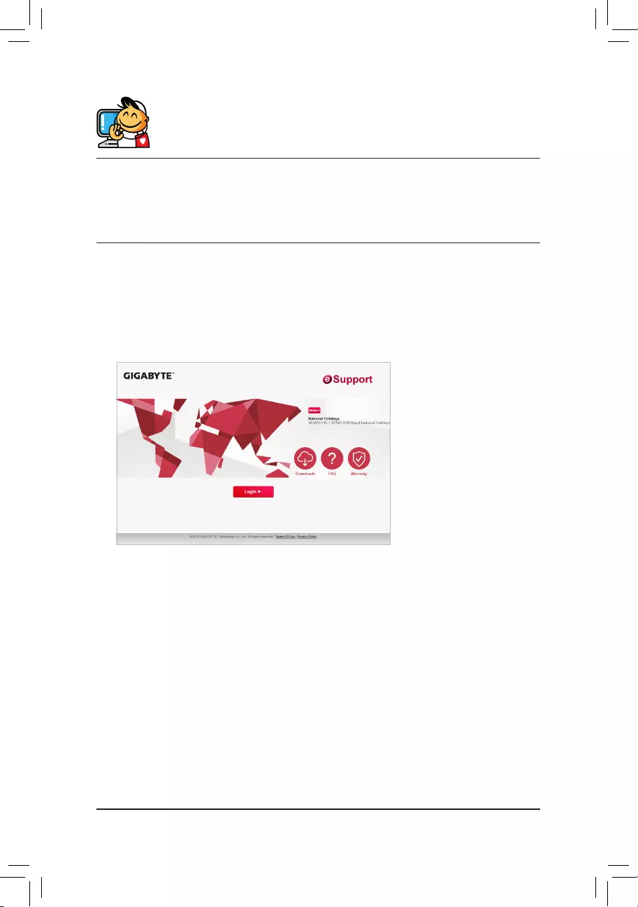
Contact Us
GIGA-BYTE TECHNOLOGY CO., LTD.
Address:No.6,BaoqiangRd.,XindianDist.,NewTaipeiCity231,Taiwan
TEL: +886—2-8912-4000, FAX: +886-2-8912-4005
Tech.andNon-Tech.Support(Sales/Marketing):https://esupport.gigabyte.com
WEB address (English): https://www.gigabyte.com
WEB address (Chinese): https://www.gigabyte.com/tw
•GIGABYTE eSupport
To submit a technical or non-technical (Sales/Marketing) question, please link to:
https://esupport.gigabyte.com
— 41 —
Gigabyte
Loading…
A
- Aorus 7 SB-7DE1130SD
- Aorus 7 SB-7UK1131SH
- Aorus ATC800
- Aorus CV27F
- Aorus CV27Q
- AORUS FI25F3
- Aorus FI27Q-P
- AORUS FI27Q-X
- Aorus FO48U
- Aorus GA-AX370-Gaming K7
- Aorus Gen4 AIC Adaptor
- Aorus KD25F
- AORUS LIQUID COOLER
- AP128DG-H
- AP64D
- AP64D-H
- AR64S-H
- ATC800
- AV32DG
- AV64S-T
- AX370-Gaming
- AX370-Gaming 5 WIFI
B
- B150M-HD3 DDR3
- B360 Aorus Gaming 3 WIFI
- B360M Aorus Gaming 3
- B360M D2V
- B360M D3H
- B360M D3P
- B360M DS3H
- B360M H
- B360M HD3
- B360N WIFI
- B365 HD3
- B365 M Aorus elite
- B365M D2V
- B365M D3H
- B365M DS3H
- B365M H
- B365M HD3
- B40W10P-FR
- B4502
- B450 Aorus elite
- B450 AORUS ELITE V22
- B450 Aorus M2
- B450 AORUS PRO
- B450 AORUS PRO WIFI
- B450 Gaming X2
- B450 I AORUS PRO WIFI2
- B450M
- B450M DS3H
- B450M DS3H V2
- B450M GAMING
- B450M H2
- B450M S2H
- B450M S2H V2
- B460 Aorus Pro AC2
- B460 HD3
- B460M Aorus Pro
- B460M D2V
- B460M D3H
- B460M DS3H2
- B460M DS3H AC
- B460M Gaming HD2
- B550
- B550 Aorus elite
- B550 AORUS ELITE AX
- B550 Aorus elite AX V2
- B550 Aorus Master
- B550 Aorus Pro3
- B550 AORUS PRO AC3
- B550 AORUS PRO AX
- B550 Aorus Pro V2
- B550 Gaming X
- B550 Gaming X V2
- B550I Aorus Pro AX
- B550M Aorus elite2
- B550M Aorus Pro
- B550M AORUS PRO-P
- B550M DS3H2
- B550M DS3H AC2
- B550M DS3H AC-Y12
- B550M GAMING
- B550M H
- B550M S2H
- B550 Vision D
- B550 VISION D-P
- B560 AORUS PROAX2
- B560 DS3H AC3
- B560I AORUS PRO AX3
- B560M AORUS ELITE3
- B560M AORUS PRO3
- B560M AORUS PRO AX3
- B560M D2V2
- B560M D3H
- B560M DS3H
- B560M DS3H AC
- B560M GAMING HD2
- B560M H
- BARBADOS-IU
- BARBADOSV-IU
Loading…
Loading…
Nothing found
B450M DS3H V2
operation manual
41 pgs11.2 Mb11
Table of contents
Loading…
…
Gigabyte operation manual
Specifications and Main Features
Frequently Asked Questions
User Manual
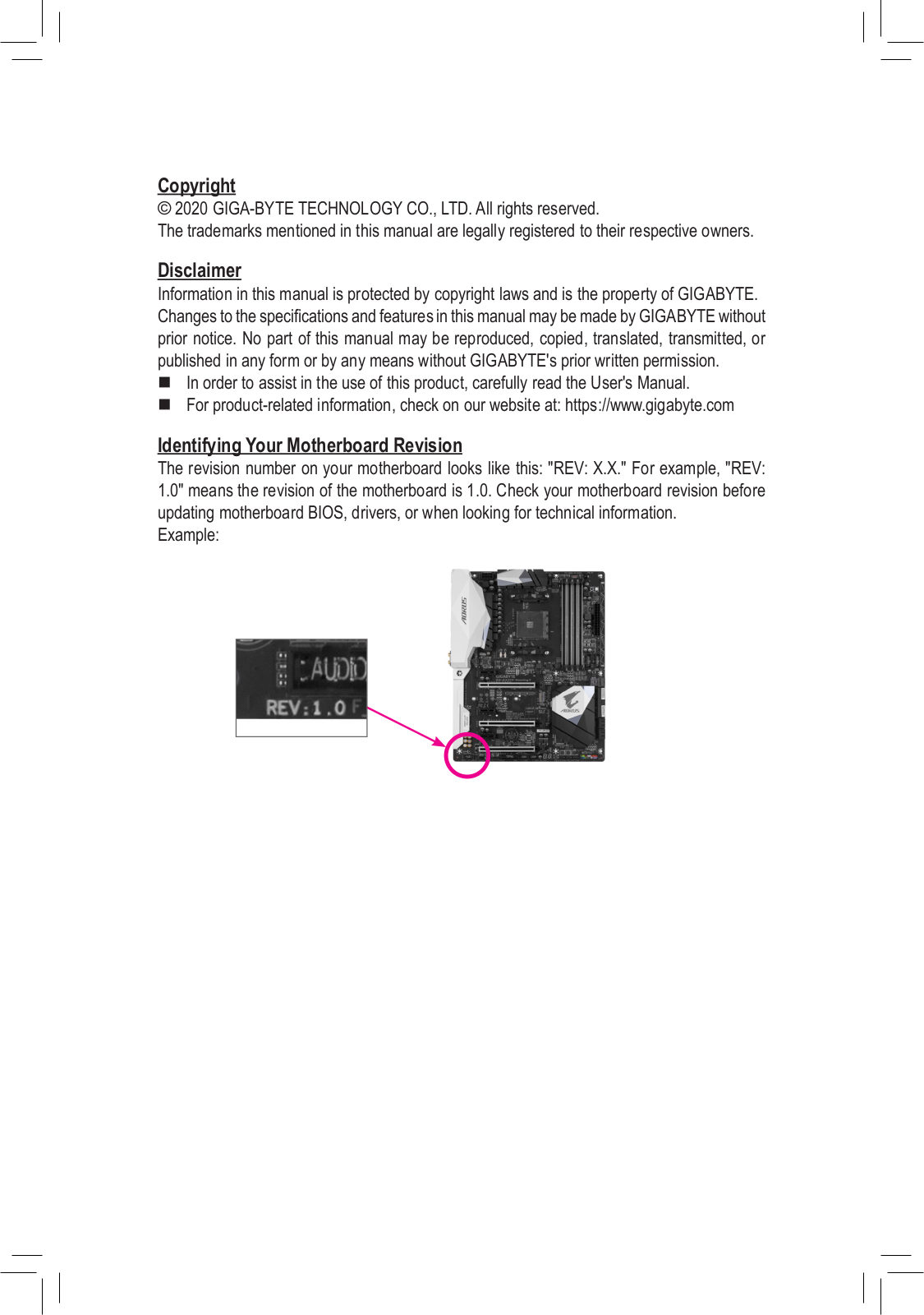
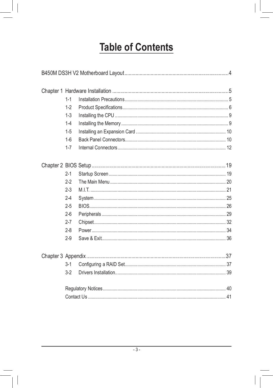
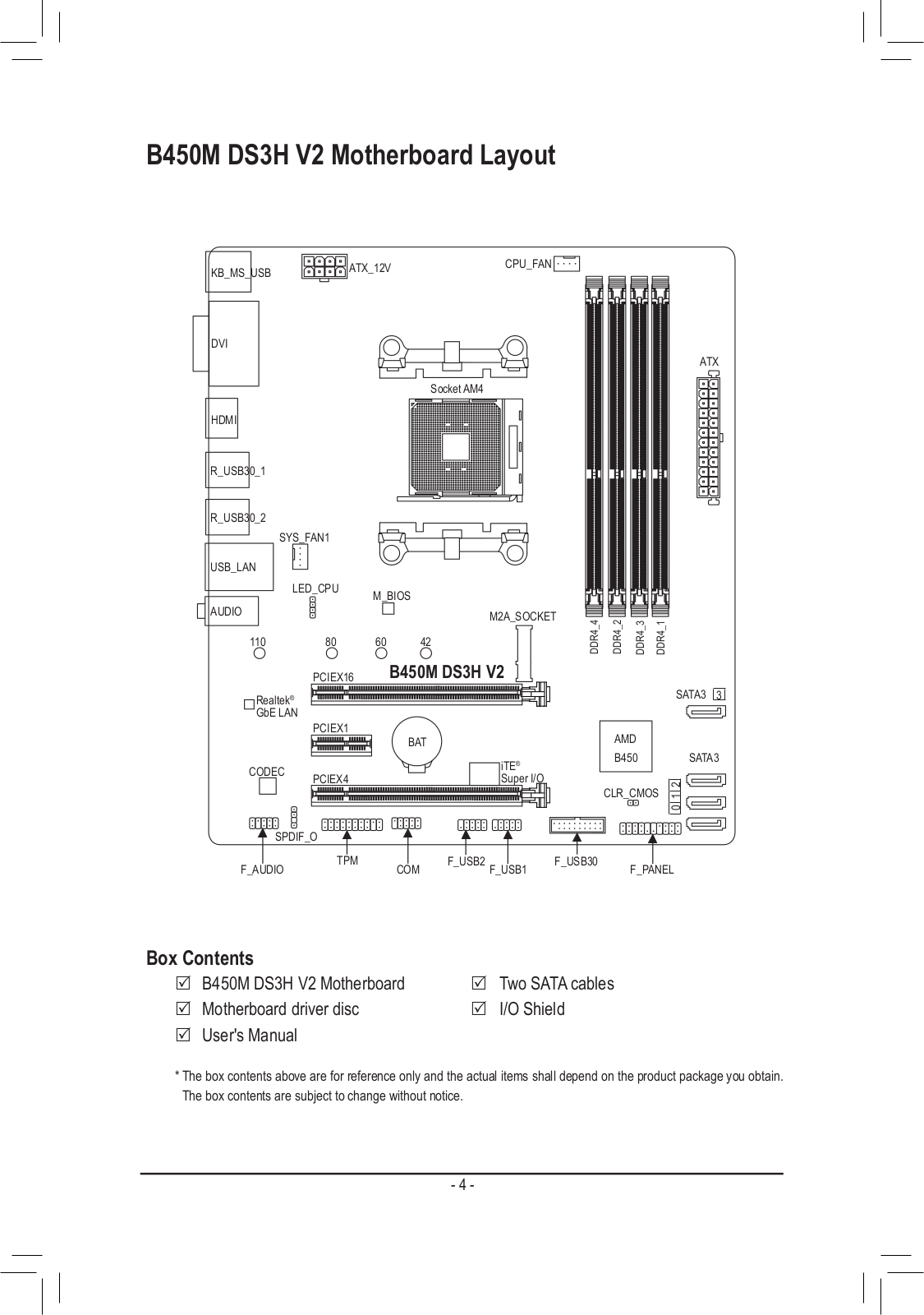


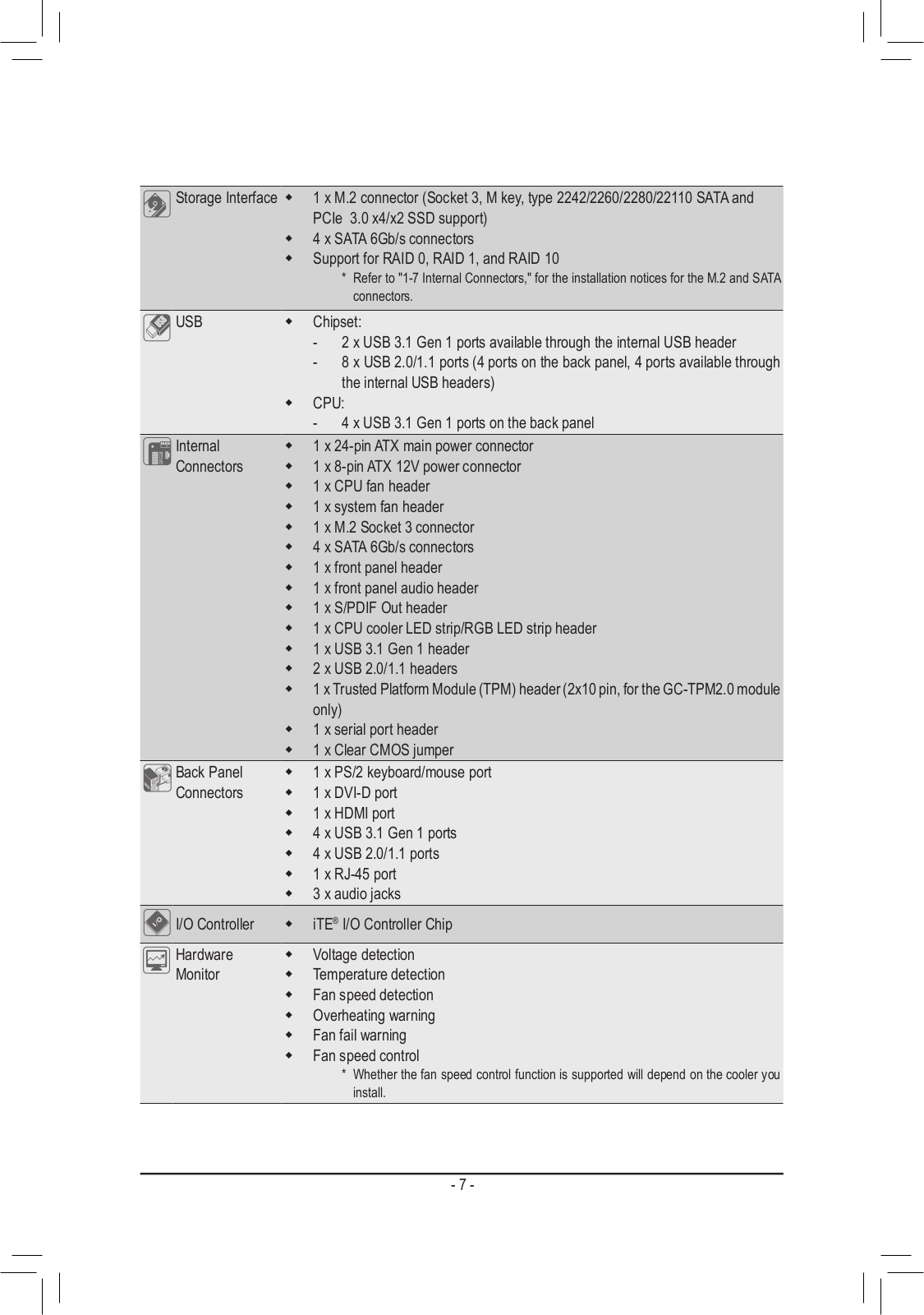
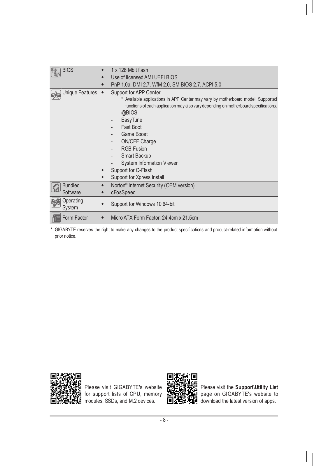
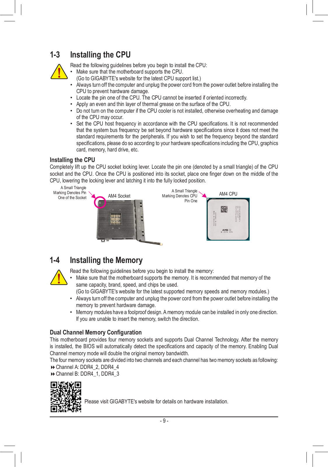
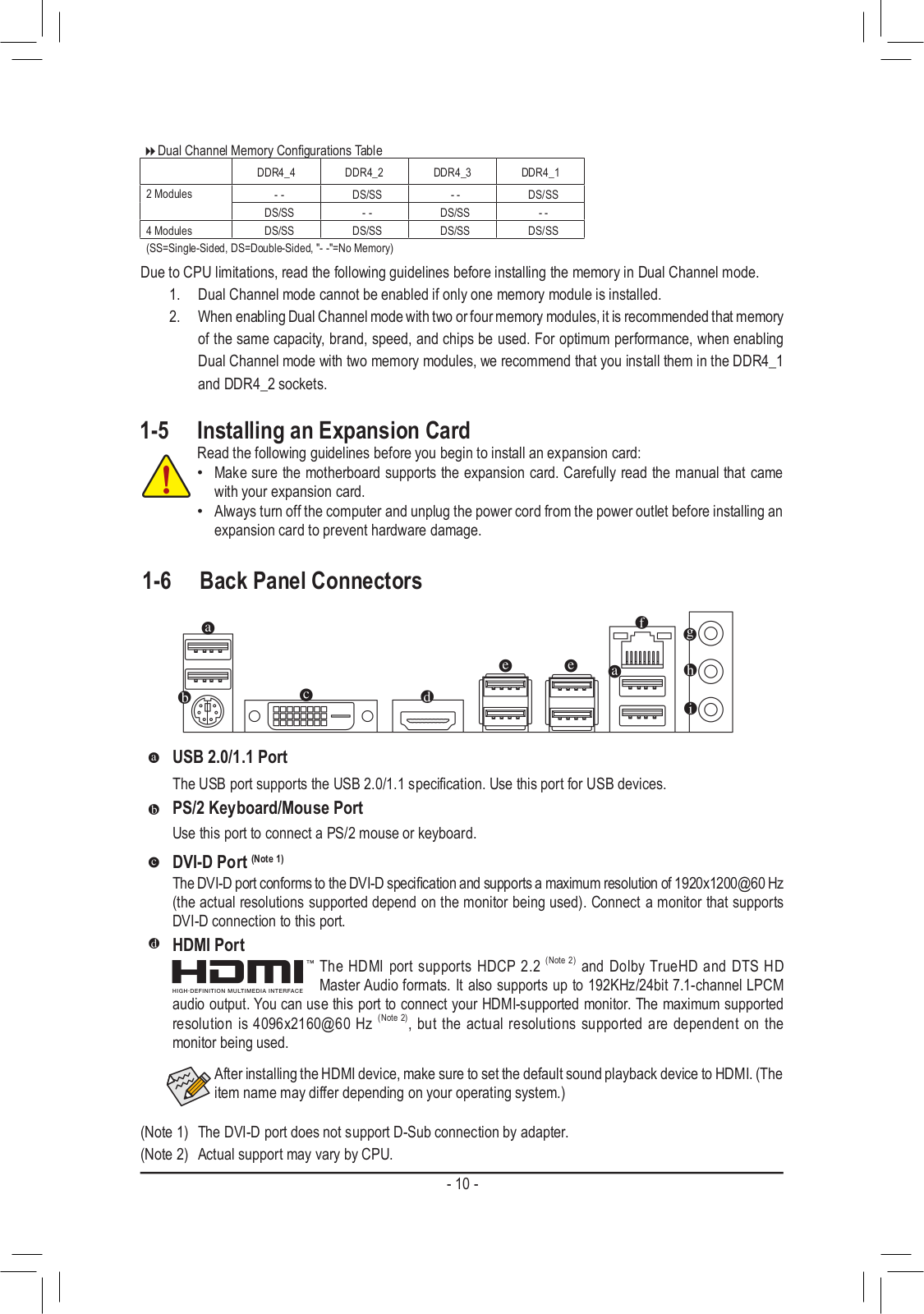
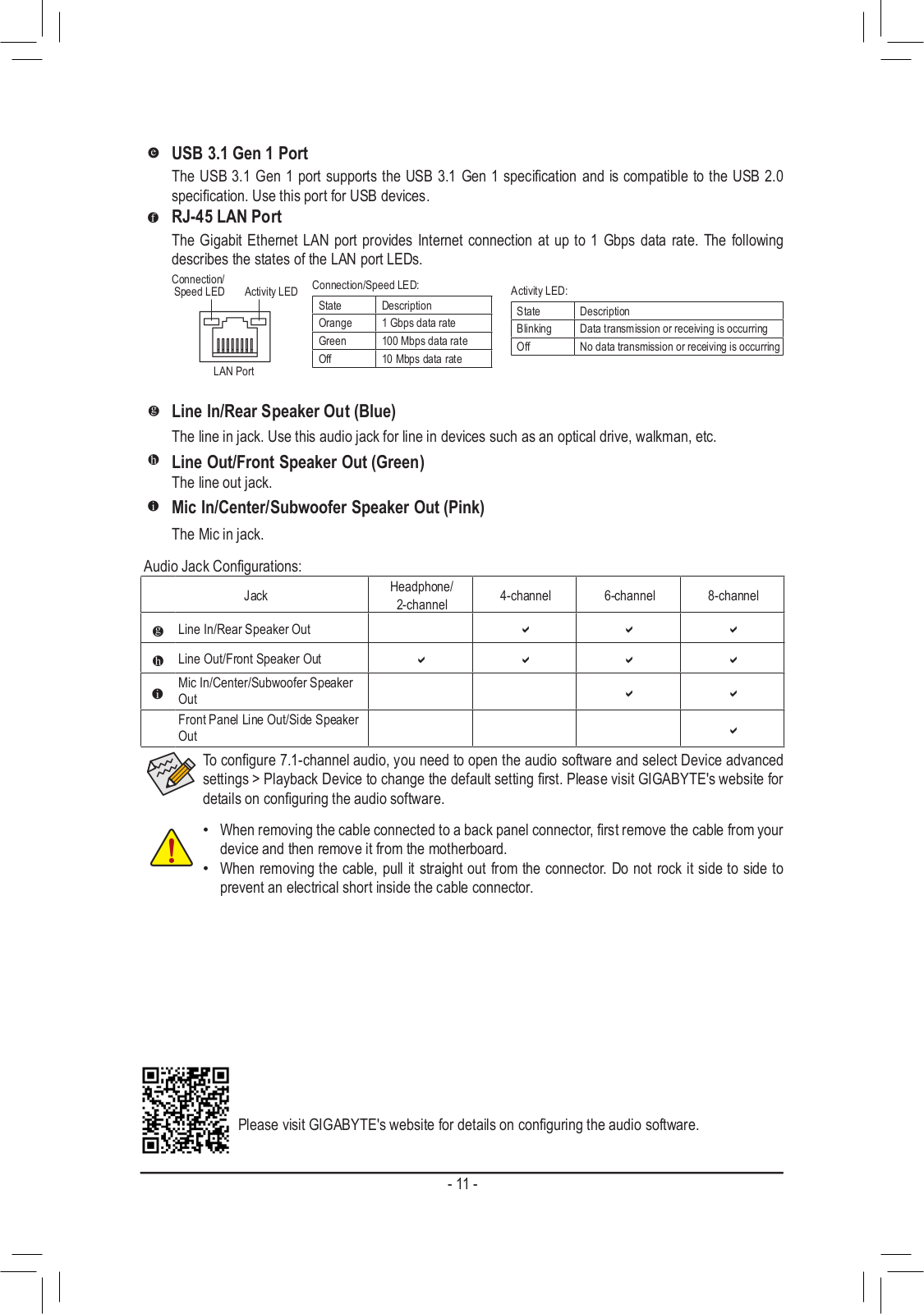
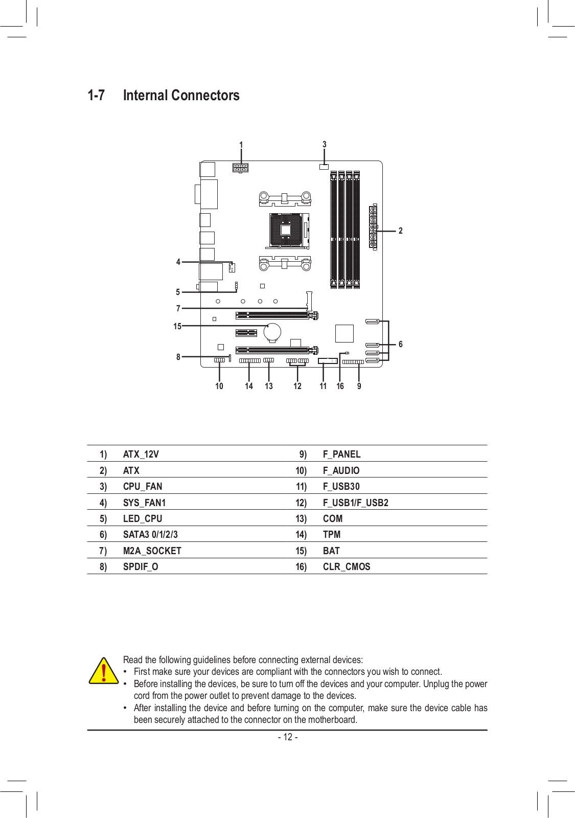
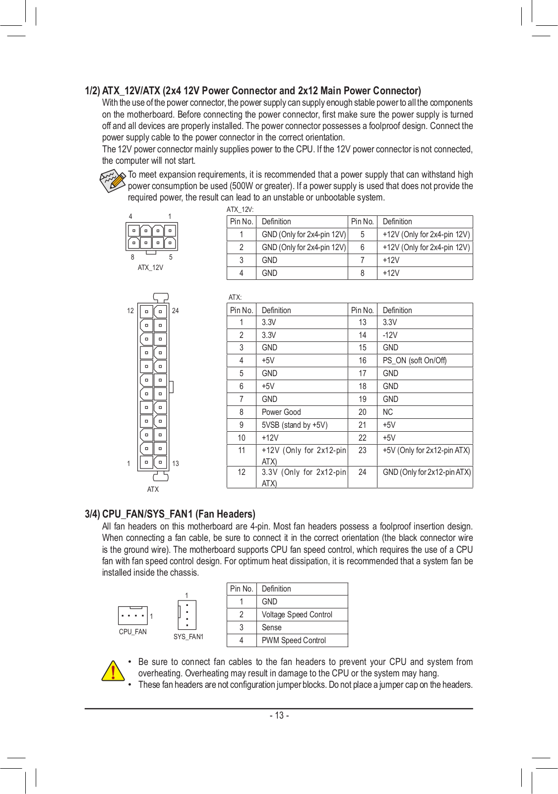
Loading…
+ 28 hidden pages
You need points to download manuals.
1 point = 1 manual.
You can buy points or you can get point for every manual you upload.
Buy points
Upload your manuals
Free Manuals for Gigabyte B450M DS3H V2 (rev. 1.0)
Manufacturer:Gigabyte
Category:Computers & Peripherals
Device:Gigabyte B450M DS3H V2 (rev. 1.0)
Name:Quick Installation Guide
Language:Português
Pages:9
Size:6.73 MB
Manufacturer:Gigabyte
Category:Computers & Peripherals
Device:Gigabyte B450M DS3H V2 (rev. 1.0)
Name:Multilingual Installation Guide
Language:العربيةБългарскиČeštinaDeutschΕλληνικάEnglishEspañolفارسىFrançaisעבריתHrvatskiMagyarBahasa IndonesiaItaliano日本語한국어PolskiPortuguêsRomânăРусскийSrpskiไทยTürkçeTiếng Việt中文
Version:103
Pages:2
Size:9.03 MB
DescriptionGigabyte B450M DS3H V2 (rev. 1.0) Multilingual Installation GuideView Gigabyte B450M DS3H V2 (rev. 1.0) Multilingual Installation Guide 103 (العربية, Български, Čeština, Deutsch, Ελληνικά, English, Español, فارسى, Français, עברית, Hrvatski, Magyar, Bahasa Indonesia, Italiano, 日本語, 한국어, Polski, Português, Română, Русский, Srpski, ไทย, Türkçe, Tiếng Việt, 中文)
Manufacturer:Gigabyte
Category:Computers & Peripherals
Device:Gigabyte B450M DS3H V2 (rev. 1.0)
Name:Manual
Language:中文中文(简体)
Version:1001
Pages:42
Size:9.65 MB
Manufacturer:Gigabyte
Category:Computers & Peripherals
Device:Gigabyte B450M DS3H V2 (rev. 1.0)
Name:Manual
Language:English
Version:1001
Pages:41
Size:10.68 MB
Manufacturer:Gigabyte
Category:Computers & Peripherals
Device:Gigabyte B450M DS3H V2 (rev. 1.0)
Name:Manual
Language:中文中文(繁體)
Version:1001
Pages:43
Size:11.54 MB
[pdf]
User Manual Installation Guide Instructions Specifications Guide
B450M DS3H WIFI 28 ago 2023 — @BIOS is a Windows based utility that searches and the latest version of BIOS from Internet updates For instructions on using Q mb manual b450m ds3h wifi e 1501 v 15d6c5567115bd7314e71f6b6d7c3aa5 gigabyte FileList Manual |||
B450M DS3H WIFI User s Manual Rev. 1501 GIGABYTE will reduce paper use in order to fulfill the responsibilities of a global citizen. Also, to reduce the impacts on global warming, the packaging materials of this product are recyclable and reusable. GIGABYTE works with you to protect the environment….
lang:en score:59 filesize: 10.76 M page_count: 29 document date: 2023-08-10
[pdf]
User Manual Instructions
B450M DS3H WIFI Gigabyte 2 版权 © 2021年 技嘉科技股份有限公司 版权所有。 Proper operation of this radio according to the instructions found in manual will result exposure mb b450m ds3h wifi sc 1201 gigabyte FileList Manual
B450M DS3H WIFI Rev. 1201 2021 https://www.gigabyte.cn/ REV : X.XX.X REV : 1.01.0BIOS — 2 — B450M DS3H WIFI …………………………………………………………………………4 ……………………………………………………………………….
lang:no score:58 filesize: 10.62 M page_count: 46 document date: 2021-01-13
[pdf]
User Manual Instructions
B450M DS3H WIFI Gigabyte 2 版權 © 2021年 技嘉科技股份有限公司 版權所有。 Proper operation of this radio according to the instructions found in manual will result exposure mb b450m ds3h wifi c 1201 gigabyte FileList Manual
B450M DS3H WIFI Rev. 1201 df dd l 2021ddf df df df df deee f df djhttps://www.gigabyte.com/tw REV : X.XfX.Xd REV : 1.0d1.0fBIOSe df j — 2 — B450M DS3H WIFI……………………………………………………………………..4 ……………………………………………
lang:no score:57 filesize: 12.38 M page_count: 46 document date: 2021-01-25
[pdf]
User Manual
mb manual b450m ds3h wifi c 1301 v e5e00e8f389fcb82a25f08494f4df4f8 gigabyte FileList Manual |||
B450M DS3H WIFI Rev. 1301 df https://www.gigabyte.com/tw/Motherboard/B450M DS3H WIFI-rev-10 m=ma#kf ddd dl 2022ddf df df df df deee f df df https://download.gigabyte.com/FileList/Manual/mb_manual_installation-guide_103.pdf m=sw djhttps://www.gigabyte.com/tw REV : X.XfX.Xd REV : 1.0d1.0fBIOS…
lang:i-klingon score:57 filesize: 11.28 M page_count: 32 document date: 2022-12-08
[pdf]
User Manual
mb manual b450m ds3h wifi v3 sc 1502 v 5c0d84c389ef8b5678cf1727e0ea4a68 gigabyte FileList Manual |||
B450M DS3H WIFI B450M DS3H V3 Rev. 1502 2024 https://download.gigabyte.cn/FileList/Manual/mb_manual_installation-guide_103.pdf m=sw https://www.gigabyte.cn/ REV : X.XX.X REV : 1.01.0BIOS — 2 — ……………………………………………………………………….
lang:i-klingon score:57 filesize: 15.3 M page_count: 34 document date: 2024-07-30
[pdf]
User Manual Installation Guide Guide
B450M DS3H WIFI 17 hours ago — ▫ 如果您要快速安装 请至技嘉网站参考【硬件安装指南】。 gigabyte cn FileList Manual mb manual installation guide 103 m sw 产品 b450m ds3h wifi sc 1501 v f9cfc2ef2c3f35200b943bb2fda708fb |||
B450M DS3H WIFI Rev. 1501 2023 https://download.gigabyte.cn/FileList/Manual/mb_manual_installation-guide_103.pdf m=sw https://www.gigabyte.cn/ REV : X.XX.X REV : 1.01.0BIOS — 2 — ……………………………………………………………………………………
lang:it score:56 filesize: 11.11 M page_count: 31 document date: 2023-08-10
[pdf]
User Manual
mb manual b450m ds3h wifi v3 c 1502 gigabyte FileList Manual |||
B450M DS3H WIFI B450M DS3H V3 Rev. 1502 ddd dl df 2024ddf df df df df deee f df df https://download.gigabyte.com/FileList/Manual/mb_manual_installation-guide_103.pdf m=sw djhttps://www.gigabyte.com/tw REV : X.XfX.Xd REV : 1.0d1.0fBIOSe df j — 2 — …………………………………..
lang:i-klingon score:56 filesize: 15.48 M page_count: 34 document date: 2024-07-30
[pdf]
User Manual Installation Guide Specifications Guide
mb manual b450m ds3h wifi v3 e 1502 v b1cf847bfff907c948cf0588059f72cf gigabyte FileList Manual |||
B450M DS3H WIFI B450M DS3H V3 User s Manual Rev. 1502 GIGABYTE will reduce paper use in order to fulfill the responsibilities of a global citizen. Also, to reduce the impacts on global warming, the packaging materials of this product are recyclable and reusable. GIGABYTE works with you to protect th…
lang:en score:55 filesize: 14.89 M page_count: 32 document date: 2024-07-30
[pdf]
User Manual
mb manual b450m ds3h wifi c 1501 v a12b79da09c00d876ac23ca2afeb6fc1 gigabyte FileList Manual |||
B450M DS3H WIFI Rev. 1501 ddd dl df 2023ddf df df df df deee f df df https://download.gigabyte.com/FileList/Manual/mb_manual_installation-guide_103.pdf m=sw djhttps://www.gigabyte.com/tw REV : X.XfX.Xd REV : 1.0d1.0fBIOSe df j — 2 — ……………………………………………….
lang:it score:55 filesize: 11.29 M page_count: 31 document date: 2023-08-10
[pdf]
User Manual Instructions Specifications
B450M DS3H WIFI Gigabyte 2021 GIGA BYTE TECHNOLOGY CO LTD and or grounding instructions 5 For how to turn on off the lights of LED strip refer in The trademarks mentioned this manual are legally registered their respective When connecting hardware components internal connectors the mb b450m ds3h wifi e 1201 gigabyte FileList Manual
B450M DS3H WIFI User s Manual Rev. 1201 For more product details, please visit GIGABYTE s website. To reduce the impacts on global warming, the packaging materials of this product are recyclable and reusable. GIGABYTE works with you to protect the environment. Copyright 2021 GIGA-BYTE TECHNOLOGY …
lang:en score:55 filesize: 11.56 M page_count: 44 document date: 2021-01-25
[pdf]
User Manual Installation Guide Specifications Guide
B450M DS3H WIFI Gigabyte 2022 12 — 2 1 Installation Precautions The motherboard contains numerous delicate electronic circuits and components which can become mb manual b450m ds3h wifi e 1301 v d66f371828020d4e6acfe38ad8fc6631 gigabyte FileList Manual |||
B450M DS3H WIFI User s Manual Rev. 1301 For more product details, please visit GIGABYTE s website. https://www.gigabyte.com/Motherboard/B450M DS3H WIFI-rev-10 m=ma#kf GIGABYTE will reduce paper use in order to fulfill the responsibilities of a global citizen. Also, to reduce the impacts on global wa…
lang:en score:52 filesize: 10.8 M page_count: 30 document date: 2022-12-08
[pdf]
User Manual Installation Guide Specifications Guide
B450M DS3H WIFI V3 31 дек 2024 г — 2 1 Installation Precautions The motherboard contains numerous delicate electronic circuits and components which can become mb manual b450m ds3h wifi v3 1503 e v afd8da7c15d1c31cefa55e7b94190112 gigabyte FileList Manual |||
B450M DS3H WIFI B450M DS3H V3 User s Manual Rev. 1503 GIGABYTE will reduce paper use in order to fulfill the responsibilities of a global citizen. Also, to reduce the impacts on global warming, the packaging materials of this product are recyclable and reusable. GIGABYTE works with you to protect th…
lang:en score:51 filesize: 14.88 M page_count: 32 document date: 2024-12-13
[pdf]
User Manual Specifications
B450M DS3H WIFI Gigabyte Mar 22 2019 — Prior to installation carefully read the user s manual and follow these procedures make sure chassis is suitable for mb b450m ds3h wifi e gigabyte FileList Manual
B450M DS3H WIFI User s Manual Rev. 1001 For more product details, please visit GIGABYTE s website. To reduce the impacts on global warming, the packaging materials of this product are recyclable and reusable. GIGABYTE works with you to protect the environment. Motherboard B450M DS3H WIFI Mar. 22, …
lang:en score:51 filesize: 12.02 M page_count: 46 document date: 2019-03-25
[pdf]
User Manual Specifications
B450M DS3H WIFI V2 Gigabyte Prior to installation carefully read the user s manual and follow these procedures make sure chassis is suitable for motherboard mb b450m ds3h wifi e 1101 gigabyte FileList Manual
B450M DS3H WIFI V2 User s Manual Rev. 1001 For more product details, please visit GIGABYTE s website. To reduce the impacts on global warming, the packaging materials of this product are recyclable and reusable. GIGABYTE works with you to protect the environment. Copyright 2020 GIGA-BYTE TECHNOLO…
lang:en score:49 filesize: 11.6 M page_count: 44 document date: 2020-09-03
[pdf]
GIGABYTE B450M DS3H WIFI AM4 Sklep internetowy stylem pl gigabyte b450m ds3h wifi am4 406240 upload files product |||
GIGABYTE B450M DS3H WIFI AM4 Indeks: 406240 Producent: GIGABYTE Kod producenta: B450M DS3H WIFI Cena: 399.29 zl Opis GIGABYTE B450M DS3H WIFI AM4 Producent: GIGABYTE Parametry Stan Nowy Zdjcia …
lang:en score:48 filesize: 383.65 K page_count: 1 document date: 2024-05-24
[pdf]
User Manual
B450M DS3H WIFI Gigabyte Dec 12 2022 — 责任声明 本使用手册受著作权保护 所撰写的内容均为技嘉所拥有。 本使用手册所提及的产品规格或相关信息 技嘉保留修改的权利。 本使用手册所提及的产品规格或相关 mb manual b450m ds3h wifi sc 1301 v 0f302063416c6a5b684fff118505c8b4 gigabyte FileList Manual |||
B450M DS3H WIFI Rev. 1301 https://www.gigabyte.cn/Motherboard/B450M DS3H WIFI-rev-10 m=ma#kf 2022 https://download.gigabyte.com/FileList/Manual/mb_manual_installation-guide_103.pdf m=sw https://www.gigabyte.cn/ REV : X.XX.X REV : 1.01.0BIOS — 2 — ……………………….
lang:i-klingon score:43 filesize: 11.3 M page_count: 32 document date: 2022-12-08
[pdf]
User Manual
Uputstvo za upotrebu EN GIGABYTE B450M DS3H WIFI rev 1 x matična ploča uputstvo en gigabyte b450m ds3h wifi maticna ploca 6630031d515f8 api tehnoteka rs 2024 04 |||
https://tehnoteka.rs Uputstvo za upotrebu EN GIGABYTE B450M DS3H WIFI rev. 1.x maticna ploca Tehnoteka je online destinacija za uporeivanje cena i karakteristika bele tehnike, potrosacke elektronike i IT ureaja kod trgovinskih lanaca i internet prodavnica u Srbiji. Nasa stranica vam omoguava da …
lang:en score:43 filesize: 10.44 M page_count: 31 document date: 2024-04-29
[pdf]
B450M DS3H WIFI DDR4 QVL Vermeer CPU 20210407 xlsx Stacy Chang mb memory b450m ds3h wifi vermeer gigabyte FileList Memory |||
Qualified Vendors List QVL B450M DS3H WIFI Vermeer CPU # of Ranks Speed Module Supplier Density x DRAM Module P/N. SS/DS Chip Brand devices 3200 AORUS 8GB 1Rx8 GP-ARS16G32 SS Hynix 3200 ADATA 8GB 1Rx8 AX4U320038G16-BR80 SS Hynix 3200 ADATA 8GB 1Rx8 AX4U320038G16-SR80 SS …
lang:en score:40 filesize: 228.25 K page_count: 8 document date: 2021-05-14
[pdf]
User Manual
mb manual b450m ds3h wifi v3 c 1502 v d2e5c83f545739e41dfbdd09051a999 gigabyte FileList Manual d2e5c83f545739e41dfbdd09051a9992 |||
…
lang:en score:30 filesize: 1 M page_count: 0 document date: 0000-00-00
[pdf]
B450M DS3H WIFI PINNACLE QVL 20190403 xlsx Stacy Chang mb memory b450m ds3h wifi pinnacle gigabyte FileList Memory |||
Qualified Vendors List QVL B450M DS3H WIFI # of Ranks Module Supplier Density x DRAM devices HyperX 8GB 1Rx8 HyperX HyperX HyperX HyperX HyperX HyperX CORSAIR CORSAIR CORSAIR G.SKILL G.SKILL ADATA ADATA ADATA ADATA GEIL GEIL PATRIOT 8GB 8GB 8GB 8GB 8GB 8GB 4GB 8GB 16GB 8GB 16GB 8GB 8GB 8GB 8G…
lang:es score:30 filesize: 203.1 K page_count: 5 document date: 2019-04-08
[pdf]
B450M DS3H WIFI Picasso DDR4 QVL 20190829 xlsx Stacy Chang mb memory b450m ds3h wifi picasso gigabyte FileList Memory |||
Qualified Vendors List QVL B450M DS3H WIFI # of Ranks Speed Module Supplier Density x DRAM Module P/N. devices 3466 HyperX 8GB 1Rx8 HX434C19FB2/8 3466 HyperX 8GB 1Rx8 HX434C19FB2K2/16 3466 HyperX 8GB 1Rx8 HX434C19FB2K4/32 3466 HyperX 8GB 1Rx8 HX434C19FW2/8 3466 HyperX 8GB…
lang:i-klingon score:30 filesize: 202.61 K page_count: 6 document date: 2019-08-30
[pdf]
B450M DS3H WIFI QVL Raven 20190403 1 xlsx Stacy Chang mb memory b450m ds3h wifi raven gigabyte FileList Memory
Qualified Vendors List QVL B450M DS3H WIFI # of Ranks Module Supplier Density x DRAM devices HyperX 8GB 1Rx8 HyperX HyperX HyperX HyperX HyperX HyperX CORSAIR CORSAIR CORSAIR CORSAIR CORSAIR CORSAIR CORSAIR CORSAIR CORSAIR CORSAIR G.SKILL G.SKILL G.SKILL G.SKILL G.SKILL ADATA ADATA ADATA ADAT…
lang:af score:29 filesize: 203.98 K page_count: 6 document date: 2019-04-08
[pdf]
B450M DS3H WIFI DDR4 QVL Matisse 20190828 xlsx Stacy Chang mb memory b450m ds3h wifi matisse gigabyte FileList Memory
Qualified Vendors List QVL B450M DS3H WIFI Speed # of Ranks Module Supplier Density x DRAM devices Module P/N. 3600 CORSAIR 4GB 1Rx8 CMK8GX4M2B3600C18 3600 CORSAIR 8GB 1Rx8 CMK32GX4M4B3600C18 ver4.31 3600 CORSAIR 8GB 1Rx8 CMK32GX4M4B3600C18R ver4.31 3600 CORSAIR 8GB 2Rx8 CMK1…
lang:i-klingon score:28 filesize: 228.87 K page_count: 8 document date: 2019-08-30
[pdf]
Untitled Gigabyte Affected Models Telepolis pl 7 giorni fa — B550 AORUS ELITE AX V2 rev 14 10 12 5 pagine info@eclypsium eclypsium ©2023 Eclypsium Inc GIGABYTE AFFECTED MODELS 2 B560M DS3H AC 1x PLUS telepolis images 2023 06 |||
GIGABYTE AFFECTED MODELS 1 Gigabyte Affected Models: A520-AORUS-ELITE-rev-10 A520-AORUS-ELITE-rev-11 A520-AORUS-ELITE-rev-12 A520I-AC-rev-1x A520M-DS3H-AC-rev-1x A520M-DS3H-V2-rev-10 A520M-DS3H-V2-rev-11 A520M-DS3H-rev-1x A520M-H-rev-1x A520M-K-V2-rev-10 A520M-K-rev-10 A520M-S2H-rev-1x A620M-GAM…
lang:i-klingon score:26 filesize: 95.68 K page_count: 5 document date: 2023-06-02
[pdf]
cdn e misija si DS3H WIFI navodila Osnovna plošča AM4 GigaByte microATX 1xHDMI 2 0 E |||
Machine Translated by Google B450M DS3H WIFI Uporabniski prirocnik Rev. 1501 GIGABYTE bo zmanjsal porabo papirja, da bi izpolnil odgovornosti svetovnega drzavljana. Da bi zmanjsali vplive na globalno segrevanje, je embalazni material tega izdelka mogoce reciklirati in ponovno uporabiti. GIGABYTE sod…
lang:hr score:24 filesize: 2.04 M page_count: 29 document date: 2024-05-03
[pdf]
TABLA PC STREAMING LITE AMD RX V1 1 pc streaming lite amd rx 29 ago 2024 — Familia de Procesador Modelo Número Núcleos hilos Socket Tipo caché en Caché del FichaTecnicaPCSTREAMINGLITEAMDRXV1 cdn cyberpuerta mx storage articles multimedia |||
PC STREAMING LITE AMD RX Especificaciones Tipo de Equipo Nmero de Parte UPC Computadora ensamblad … L2 3 MB 3.9 GHz 4.4 GHz Tarjeta Madre Familia del Chipset Tipo de Producto Sistema de Audio B450 B450M DS3H WIFI Audio de alta calidad Memoria RAM Mamoria Interna 16 GB Tipo de Memoria Interna …
lang:es score:22 filesize: 162.06 K page_count: 1 document date: 2024-07-30
[pdf]
TABLA PC STREAMING LITE AMD GTX V1 0 FichaTecnicaPCSTREAMINGLITEAMDGTXV1 cdn cyberpuerta mx storage articles multimedia |||
PC STREAMING LITE AMD GTX Especificaciones Tipo de Equipo Nmero de Parte UPC Computadora ensambla … L2 3 MB 3.9 GHz 4.4 GHz Tarjeta Madre Familia del Chipset Tipo de Producto Sistema de Audio B450 B450M DS3H WIFI Audio de alta calidad Memoria RAM Mamoria Interna 16 GB Tipo de Memoria Interna …
lang:es score:22 filesize: 165.86 K page_count: 1 document date: 2024-07-30
[pdf]
Microsoft Word Especificaciones Técnicas para adria Cyberpuerta mx 2022 11 06 — Tarjeta Gráfica de Video EVGA GeForce RTX 2060 1920 Nucleos CUDA 6GB GDDR6 192 Bit 14000MHz 7680×4320 Pixeles PCI Express 3 0 1x HDMI OPG779932 cdn cyberpuerta storage articles multimedia |||
Producto: Computadora OPG Gamer, Ryzen 5 5600, T. de Video EVGA RTX 2060, 16GB 2x8GB RAM, SSD 480, … l Green SN350 480GB, NVMe, PCIe, Lectura 2400 MB/s, Escritura 1650 MB/s, M.2 Tarjeta Madre Gigabyte B450M DS3H WIFI, AMD AM4, 4x Puertos DDR4, PCI-EX 16, Micro ATX, USB 3.1 GEN 1, M.2 Skt 3, Audio HD,…
lang:es score:21 filesize: 795.3 K page_count: 2 document date: 2022-10-22
[pdf]
Corsair Hydro X Series XC5 RGB CPU Water Block AM4 ASUS TUF B450 Plus Gaming Prime B450M K A ROG Strix I Biostar B450MH Gigabyte DS3H Aorus M Pro WiFi MSI Carbon AC Tomahawk Mortar VDH performance pcs product file id 32625 name |||
Performance-PCs.com 1701 R. J. Conlan Blvd. NE, Unit #5 Palm Bay, FL 32905, USA Toll Free: 888-381- … SRock B450M Pro4-F MSI MAG X570 Tomahawk WIFI ASRock X370M-HDV R4.0 Gigabyte B450 Gaming X Gigabyte B450M DS3H WIFI Gigabyte B450M Aorus Elite Gigabyte X570 Aorus Elite WIFI Gigabyte X470 Aorus Gaming…
lang:en score:19 filesize: 7.94 M page_count: 16 document date: 2022-03-28
[pdf]
НКЦКИ Список новых уязвимостей ПО Уведомления Портал по информационной безопасности VULN 2023 06 05 1 safe surf ru upload new |||
-: cert.gov.ru E-mail: threats cert.gov.ru VULN.2023-06-05.1 5 2023 TLP: WHITE / … ing X rev 1.x: B450M AORUS ELITE rev 1.x: B450M DS3H rev 1.x: 1 B450M DS3H V2 rev 1.x: B450M DS3H WIFI rev 1.x: B450M GAMING rev 1.x: B450M H rev 1.x: B450M K rev 1.0: B450M S…
lang:i-klingon score:16 filesize: 211.97 K page_count: 17 document date: 2023-06-05
[pdf]
Osman Syed GA 8IEMK 8SIMLP rev 2 x 8SR533P 3 8PE667 1 0 7VKMP 7VA 8ST667 L BX2000 6VX A1 2svI7 WS images eu ssl amazon I |||
My motherboard provides Wake On LAN feature as you mentioned. But, I don t know how to enable the fe … 0 C621 AORUS XTREME rev. 1.0 Z390 AORUS XTREME WATERFORCE 5G rev. 1.0 B365M HD3 rev. 1.0 B450M DS3H WIFI rev. 1.0 GA-H310MSTX-HD3 rev. 1.0 GA-H310MSTX-HD3-CM rev. 1.0 X570 AORUS MA…
lang:i-klingon score:11 filesize: 1.96 M page_count: 73 document date: 2019-06-29
На чтение9 мин
Опубликовано
Обновлено
BIOS (Basic Input/Output System) является программным обеспечением компьютера, которое отвечает за инициализацию аппаратных компонентов и загрузку операционной системы. В данной инструкции мы рассмотрим особенности использования BIOS материнской платы Gigabyte B450M DS3H V2, чтобы обеспечить оптимальную работу компьютера.
Перед началом настройки BIOS рекомендуется создать резервную копию текущих настроек. Для этого в BIOS выберите вкладку «Save & Exit» и нажмите «Save Changes and Restart». Это позволит сохранить текущие настройки в файле на жестком диске компьютера.
Один из наиболее важных параметров, которые можно настроить в BIOS, — это режим загрузки компьютера. Вы можете выбрать между режимами Legacy и UEFI. Режим UEFI предлагает больше возможностей для защиты и безопасности компьютера, а также позволяет использовать диски большой емкости. Режим Legacy является старомодным режимом и используется только в старых операционных системах.
Другим важным параметром BIOS является частота работы процессора. Она может быть регулируемой или фиксированной. Рекомендуется указывать фиксированное значение частоты, чтобы избежать проблем с перегревом и нестабильной работой компонентов. Установите значение частоты, соответствующее техническим характеристикам вашего процессора.
Настраивая BIOS, не забудьте обновить его до последней версии с официального сайта материнской платы. Обновление BIOS может улучшить совместимость с новыми аппаратными компонентами, а также исправить возможные ошибки и уязвимости.
Как использовать BIOS Gigabyte B450M DS3H V2
Шаг 1: Загрузка в BIOS
Для того чтобы получить доступ к BIOS, необходимо перезагрузить компьютер и нажать определенную клавишу на клавиатуре перед загрузкой операционной системы. Для материнской платы Gigabyte B450M DS3H V2 это обычно клавиша DEL или F2. Нажимайте выбранную клавишу несколько раз, чтобы быть уверенными в том, что BIOS был успешно вызван.
Шаг 2: Навигация в BIOS
После входа в BIOS, вам будет предоставлен интерфейс, состоящий из различных вкладок и меню. Для навигации по BIOS используйте стрелки на клавиатуре. Некоторые настройки могут быть доступны только после смены режима на «Расширенный» или «Профессиональный».
Шаг 3: Основные настройки
Во вкладке «Main» вы можете проверить и изменить основные настройки системы, такие как дата и время, тип процессора и количество памяти. Убедитесь, что все настройки соответствуют вашей конфигурации оборудования.
Шаг 4: Настройка памяти
Для оптимальной работы системы можно настроить параметры памяти. Во вкладке «Memory» вы можете изменить такие параметры, как тактовая частота, время задержки и напряжение. Но будьте осторожны при изменении этих параметров, неправильные настройки могут привести к нестабильной работе системы.
Шаг 5: Режим загрузки
Во вкладке «Boot» вы можете настроить порядок загрузки устройств и выбрать, с какого устройства загружаться. Например, вы можете выбрать загрузку с жесткого диска или USB-флешки. Также здесь можно настроить UEFI режим загрузки.
Шаг 6: Сохранение изменений
После того как вы внесли все необходимые изменения, не забудьте сохранить их. В BIOS Gigabyte B450M DS3H V2 это можно сделать нажатием клавиши F10. При этом вам будет предложено подтвердить сохранение настроек. После сохранения изменений компьютер будет перезагружен с новыми настройками.
Надеемся, эта инструкция помогла вам освоить основные возможности BIOS Gigabyte B450M DS3H V2. Использование BIOS позволяет настроить систему для максимальной производительности и стабильной работы. Однако будьте аккуратны при изменении настроек, неправильные настройки могут повредить оборудование или привести к некорректной работе системы.
Основные настройки для оптимальной работы
Для достижения оптимальной работы вашего компьютера с BIOS Gigabyte B450M DS3H V2 рекомендуется настроить следующие параметры:
1. Оперативная память (RAM):
Убедитесь, что установлена подходящая оперативная память. Проверьте, соответствует ли скорость оперативной памяти указанной максимальной скорости на материнской плате. Если нет, вам может потребоваться изменить настройки в BIOS.
2. Центральный процессор (CPU):
Убедитесь, что ваш процессор работает с правильными настройками. Если у вас есть возможность, активируйте функцию «Core Performance Boost» (Автоматический разгон), чтобы повысить производительность.
3. Диски:
Настройте порядок загрузки (boot order), чтобы ваш операционная система загружалась с правильного диска. В BIOS Gigabyte B450M DS3H V2 эту настройку можно изменить в разделе «Boot» (Загрузка).
4. Вентиляторы:
Проверьте, чтобы все вентиляторы правильно функционировали и достаточно охлаждали вашу систему. В BIOS вы можете настроить скорость вращения вентиляторов в разделе «Hardware Monitor» (Мониторинг оборудования).
5. Энергосбережение:
В разделе «Power Management» (Управление питанием) BIOS Gigabyte B450M DS3H V2 вы можете настроить энергосберегающие функции, такие как спящий режим (sleep mode) или режим гибернации (hibernation mode). Это позволит снизить потребление энергии компьютером во время простоя.
6. Периферийные устройства:
Проверьте, чтобы все подключенные периферийные устройства, такие как клавиатура, мышь и USB-устройства, правильно работали. В BIOS Gigabyte B450M DS3H V2 вы можете настроить порты USB и другие параметры периферийных устройств в соответствующих разделах.
Помните, что внесение изменений в BIOS может повлиять на работу вашего компьютера. Будьте осторожны и учтите все возможные риски.
Раздел настроек процессора для улучшения производительности
BIOS Gigabyte B450M DS3H V2 предлагает несколько важных настроек, которые могут помочь оптимизировать производительность процессора вашего компьютера. В этом разделе мы рассмотрим некоторые из них.
- Control CPU Core Ratio (Управление частотой ядра процессора): Эта настройка позволяет вам изменять частоту работы каждого ядра процессора. Вы можете повысить или понизить частоту в зависимости от ваших потребностей. Обратите внимание, что повышение частоты может повлечь за собой увеличение тепловыделения и требования к системному охлаждению.
- Voltage Control (Управление напряжением): Эта опция позволяет вам изменять напряжение питания процессора. Если вы понижаете напряжение, можно достичь более низкой тепловыделения и энергопотребления, однако это может снизить стабильность работы системы. Будьте осторожны при настройке этой опции и следуйте рекомендациям производителя вашего процессора.
- Advanced Frequency Settings (Расширенные настройки частоты): В этом разделе вы можете вручную настроить различные параметры частоты, такие как базовая частота, множитель, память CPU и другие параметры. Это может быть полезно для экспериментов с разгоном процессора, но требует опыта и знаний в этой области. Будьте осторожны при настройке этих параметров, чтобы не повредить ваш процессор.
- Power Supply Idle Control (Управление питанием в режиме ожидания): Эта настройка позволяет управлять энергопотреблением процессора в режиме ожидания. Вы можете выбрать оптимальный режим для вашей системы, чтобы снизить энергопотребление и сохранить заряд батареи (если у вас ноутбук).
- С-State settings (Настройки С-состояний): В этом разделе вы можете настроить различные С-состояния (например, C1E, C3, C6 и другие), которые позволяют процессору переходить в энергосберегающие состояния при низкой нагрузке. Это может помочь снизить тепловыделение и энергопотребление вашего процессора.
Помните, что настройка BIOS может повлиять на стабильность работы системы и может потребоваться некоторое экспериментирование, чтобы достичь оптимальных результатов. Если вы не уверены, лучше проконсультироваться с производителем процессора или другими специалистами перед внесением изменений в BIOS.
Настройки памяти для оптимальной работы системы
Для достижения оптимальной работы системы на компьютере с материнской платой Gigabyte B450M DS3H V2 рекомендуется правильно настроить параметры памяти в BIOS.
В BIOS есть несколько настроек, которые можно изменить для оптимизации работы памяти:
| Настройка | Описание |
|---|---|
| DRAM Frequency | Выберите частоту работы памяти в соответствии с ее спецификациями. Рекомендуется выбрать наивысшую устойчивую частоту, поддерживаемую процессором и памятью. |
| XMP | Если ваша память поддерживает Intel XMP (Extreme Memory Profile) или AMD AMP (AMD Memory Profile), активируйте эту опцию для автоматической настройки оптимальных параметров памяти. |
| Тайминги памяти | Измените тайминги памяти в соответствии с рекомендациями производителя памяти. Установите значения CAS Latency (CL), RAS to CAS Delay (tRCD), RAS Precharge Time (tRP) и RAS Active Time (tRAS) для достижения оптимальной производительности. |
| Voltage Control | При необходимости, измените напряжение памяти для улучшения стабильности системы. Однако следите за рекомендациями производителя, чтобы избежать повреждения компонентов. |
| Тестирование стабильности | После внесения изменений в настройки памяти, рекомендуется пройти тесты стабильности, чтобы убедиться, что система работает без ошибок и сбоев. |
Имейте в виду, что настройки памяти могут отличаться в зависимости от конкретной модели материнской платы Gigabyte B450M DS3H V2 и использованных модулей памяти. При сомнениях следуйте рекомендациям производителей или проконсультируйтесь с опытными пользователями или специалистами.
Настройки видеокарты для повышения графической производительности
Для оптимального использования видеокарты в BIOS Gigabyte B450M DS3H V2 рекомендуется установить следующие настройки:
- Перейдите в раздел «Advanced BIOS Features».
- Выберите опцию «Init Display First».
- Установите значение «PCIe Slot» или «PCIe Graphics Card» для первоначальной загрузки видео с видеокарты.
- Перейдите в раздел «Chipset».
- Выберите опцию «Internal Graphics».
- Отключите встроенную видеокарту, если используете дискретную видеокарту.
- Перейдите в раздел «Peripherals».
- Выберите опцию «AGP & PCI Express Configuration».
- Установите значение «PCIe Speed» на «Gen3» для достижения максимальной производительности видеокарты.
- Перейдите в раздел «Power Management Setup».
- Выберите опцию «AC PECI» и установите значение «Enabled».
- Это позволит видеокарте управлять энергопотреблением для оптимальной производительности.
После настройки данных параметров в BIOS вы сможете достичь повышения графической производительности вашей видеокарты на материнской плате Gigabyte B450M DS3H V2.
Раздел настроек питания: продлите срок службы компонентов
Настройка питания компонентов в BIOS Gigabyte B450M DS3H V2 может значительно повлиять на их производительность и срок службы. Оптимальное питание обеспечит стабильную работу системы и улучшит ее эффективность. В данном разделе мы рассмотрим основные настройки питания и дадим рекомендации для продления срока службы компонентов.
- Включение энергосберегающих функций
-
В BIOS Gigabyte B450M DS3H V2 доступны различные энергосберегающие функции, такие как Cool’n’Quiet и Core C6 State. Включение этих функций позволит снизить энергопотребление и повысить эффективность системы.
- Настройка режима работы процессора
-
Выбор оптимального режима работы процессора также важен для продления срока службы компонентов. Рекомендуется выбрать режим работы, который соответствует потребностям вашей системы и не приведет к его перегреву.
- Настройка вентиляторов системы
-
Правильная настройка вентиляторов системы поможет поддерживать оптимальную температуру компонентов и предотвращать их перегрев. В BIOS Gigabyte B450M DS3H V2 доступна возможность регулирования скорости вращения вентиляторов в соответствии с температурой процессора и системной платы.
- Проверка и обновление BIOS
-
Регулярная проверка и обновление BIOS позволяют исправить ошибки и улучшить стабильность работы системы. В некоторых случаях обновление BIOS может также повысить эффективность использования питания и продлить срок службы компонентов.
Следуя вышеуказанным рекомендациям и настраивая питание в BIOS Gigabyte B450M DS3H V2 с учетом особенностей вашей системы, вы сможете значительно продлить срок службы компонентов и повысить эффективность работы всей системы.
Дополнительные настройки для улучшения работы системы
Помимо основных настроек, BIOS Gigabyte B450M DS3H V2 предоставляет возможность провести ряд дополнительных настроек, которые могут улучшить работу вашей системы. Ниже представлены некоторые из таких настроек:
- Настройка питания процессора: Вы можете регулировать напряжение и частоту работы процессора для достижения оптимальной производительности. Однако будьте предельно осторожны при увеличении напряжения, так как это может привести к перегреву или повреждению процессора.
- Настройка памяти: Если у вас установлено несколько модулей оперативной памяти, вы можете провести настройку их работы для повышения производительности. Gigabyte B450M DS3H V2 поддерживает различные профили памяти, которые могут быть активированы для достижения максимального потенциала вашей памяти.
- Настройка системного разгона: BIOS Gigabyte B450M DS3H V2 предоставляет возможность провести разгон системы для увеличения ее производительности. Однако будьте осторожны, так как неумеренный разгон может привести к перегреву и повреждению компонентов системы.
- Настройки вентиляторов: Вы можете провести настройку работы вентиляторов системы для обеспечения оптимальной температуры внутри корпуса. Gigabyte B450M DS3H V2 предоставляет возможность регулирования скорости вращения вентиляторов в зависимости от температуры процессора или других компонентов.
- Настройка загрузки системы: Gigabyte B450M DS3H V2 предоставляет возможность настроить порядок загрузки устройств. Вы можете указать, с какого устройства должна загружаться система в первую очередь, что особенно полезно, если у вас установлено несколько носителей операционной системы.
Не забывайте, что проведение дополнительных настроек в BIOS может повлиять на стабильность и работу вашей системы. Перед проведением каких-либо изменений рекомендуется ознакомиться с документацией вашей материнской платы и уточнить, какие настройки могут быть оптимальными для вашей системы.