
MSI
Loading…
#
- 945GC
- 945GCM478
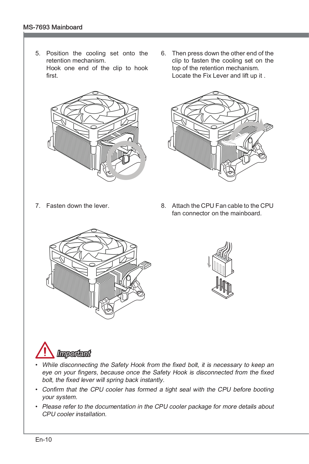
- 945GCM53
- 945GCM5 V2
- 945GCM7
- 945GCM7-F
- 945GC Network
- 945GM
- 945GM1
- 945GM22
- 945GM2-F3
- 945GM2-FI3
- 945GM2-FR3
- 945GM2 — Fuzzy Motherboard — Mini ITX
- 945GM3
- 945GM3-F
- 945GM4-FI
- 945GM5
- 945GME
- 945GME1
- 945GME22
- 945GME3
- 945G Neo
- 945G Neo23
- 945G Platinum2
- 945GZM2-F
- 945GZM3
- 945GZM5
- 945GZM6
- 945P
- 945PLM2
- 945PL Neo2
- 945PL Neo22
- 945PL Neo32
- 945PL Neo52
- 945P MS-7204
- 945P Neo3
- 945P Neo2
- 945P Neo2-F2
- 945P Neo32
- 945P Neo52
- 945P Neo5-F
- 945P Platinum
- 946GZM
- 946GZ Neo
- 946PLM
- 955X Platinum
- 970A
- 970A-G432
- 970A-G43 PLUS
- 970A-G452
- 970A-G46
- 970A SLI Krait Edition
- 975X Platinum3
- 990FXA
- 990FXA GAMING2
- 990FXA-GD654
- 990FXA-GD803
- 990FXA-GD80 G52-76401XB
- 990FXA-GD80V2
- 990XA-GD554
- 9M-028XEU AiO
- 9M-029XEU AiO
- 9M-081EU AiO
- 9M-239DE AiO
- 9RB-033EU
- 9S6-3BA41T-006
- 9S6-3CA51T-012
- 9S6-3CA66T-009
- 9S6-3CB51T-008
- 9S6-3DA05T-0162
- 9S6-3DA19A-0012
- 9S6-3DA45A-001
- 9S6-3DA75A-012
- 9S6-3DA88T-001
- 9S6-3EA01H-0122
- 9S6-3EA24T-061
- 9S6-3FA35T-0402
- 9S6-3FA64T-0612
- 9S6-3FA75T-002
- 9S6-3KA01H-029
- 9S6-3MA01H-013
- 9S6-B92631-870
- 9S6-B93211-017
- 9S6-B93311-052
- 9S7-122816-017 — VR220 017US-GST3402G25SP — Pentium 2.16 GHz
- 9S7-169112-031 — X600 031US — Core 2 Solo 1.4 GHz
- 9S7-171A86-1W6 — Gaming GX710-400
- 9S7-179BC3-814
- 9S7-179C11-078
- 9S7-17A121-2852
- 9S7-17B112-2082
- 9S7-17B112-424
- 9SC-210CZ
- 9SC-480CZ
- 9SC-608RU
- 9SD-093CZ
- 9SD-219CZ
- 9SD-222CZ
- 970
Loading…
Loading…
Nothing found
970A-G43
User Manual
80 pgs7.16 Mb5
User Manual [ru]
156 pgs12.81 Mb2
Table of contents
Loading…
…
MSI User Manual [ru]
Download
Specifications and Main Features
Frequently Asked Questions
User Manual

Loading…
+ 126 hidden pages
You need points to download manuals.
1 point = 1 manual.
You can buy points or you can get point for every manual you upload.
Buy points
Upload your manuals

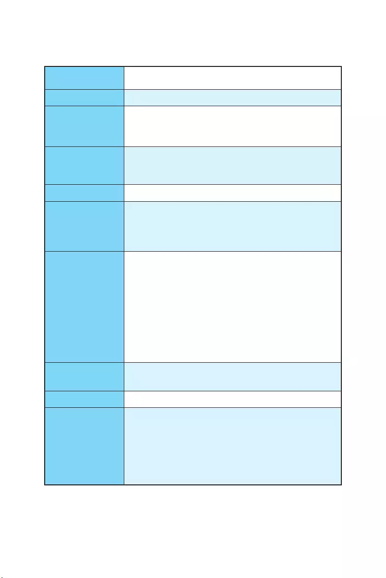
1
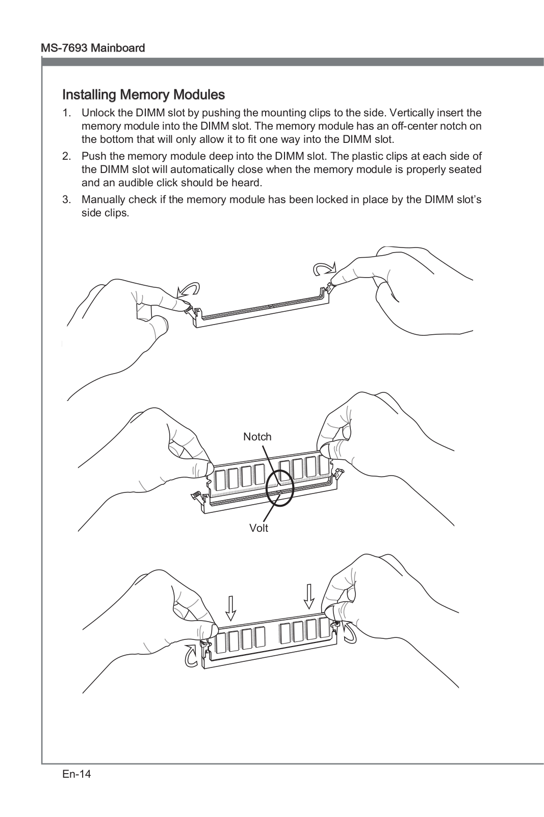
Unpacking
Unpacking
Thank you for buying the MSI® 970A-G43 PLUS motherboard. Check to make sure your
motherboard box contains the following items. If something is missing, contact your
dealer as soon as possible.
SATA Cable x2
Drivers & Utilities
Disc
Motherboard User
Guide
I/O Shield
Motherboard

2Safety Information
Safety Information
yThe components included in this package are prone to damage from electrostatic
discharge (ESD). Please adhere to the following instructions to ensure successful
computer assembly.
yEnsure that all components are securely connected. Loose connections may cause
the computer to not recognize a component or fail to start.
yHold the motherboard by the edges to avoid touching sensitive components.
yIt is recommended to wear an electrostatic discharge (ESD) wrist strap when
handling the motherboard to prevent electrostatic damage. If an ESD wrist strap
is not available, discharge yourself of static electricity by touching another metal
object before handling the motherboard.
yStore the motherboard in an electrostatic shielding container or on an anti-static
pad whenever the motherboard is not installed.
yBefore turning on the computer, ensure that there are no loose screws or metal
components on the motherboard or anywhere within the computer case.
yDo not boot the computer before installation is completed. This could cause
permanent damage to the components as well as injury to the user.
yIf you need help during any installation step, please consult a certified computer
technician.
yAlways turn off the power supply and unplug the power cord from the power outlet
before installing or removing any computer component.
yKeep this user guide for future reference.
yKeep this motherboard away from humidity.
yMake sure that your electrical outlet provides the same voltage as is indicated on
the PSU, before connecting the PSU to the electrical outlet.
yPlace the power cord such a way that people can not step on it. Do not place
anything over the power cord.
yAll cautions and warnings on the motherboard should be noted.
yIf any of the following situations arises, get the motherboard checked by service
personnel:
Liquid has penetrated into the computer.
The motherboard has been exposed to moisture.
The motherboard does not work well or you can not get it work according to user
guide.
The motherboard has been dropped and damaged.
The motherboard has obvious sign of breakage.
yDo not leave this motherboard in an environment above 60°C (140°F), it may damage
the motherboard.
3
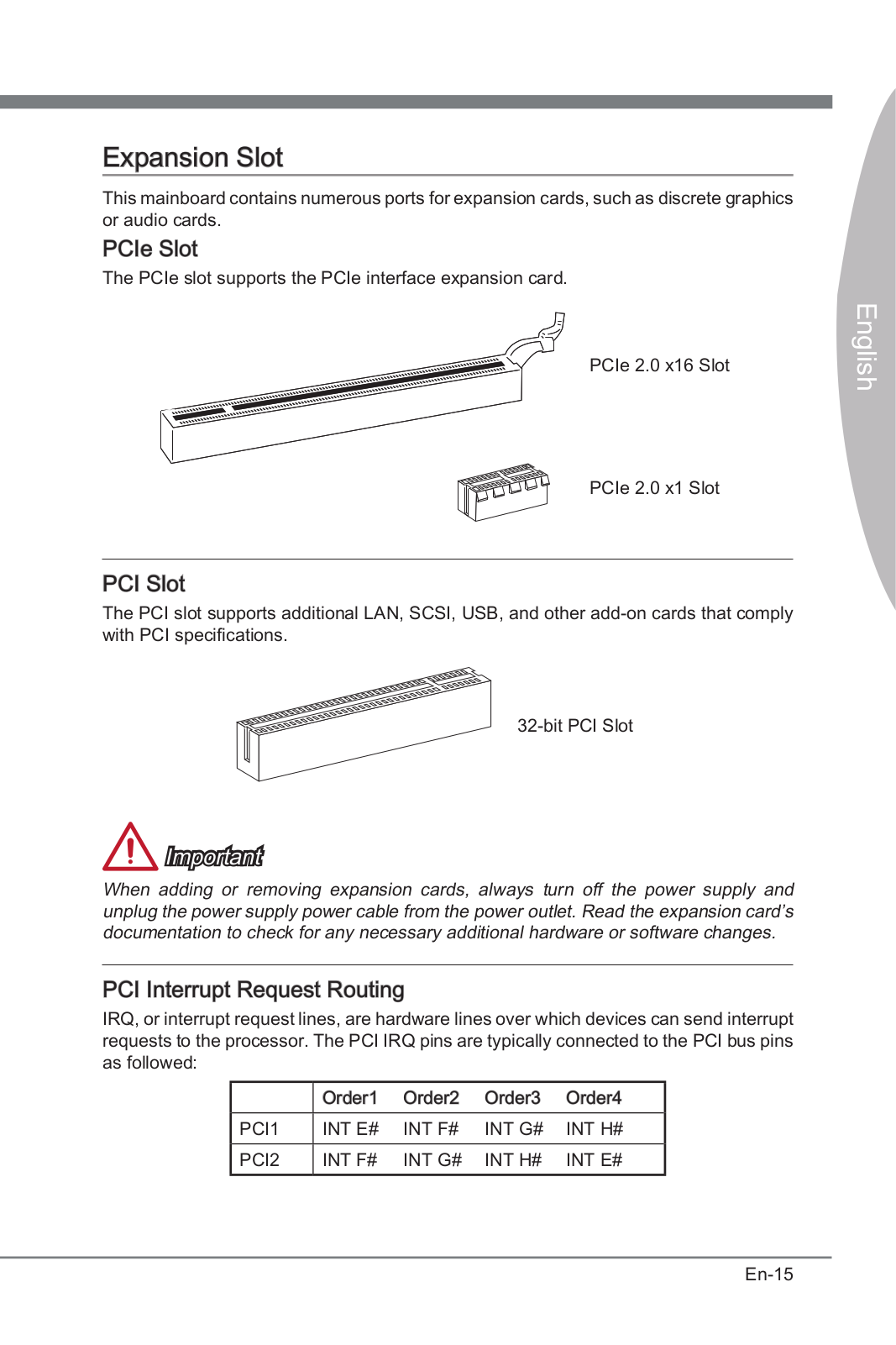
Quick Start
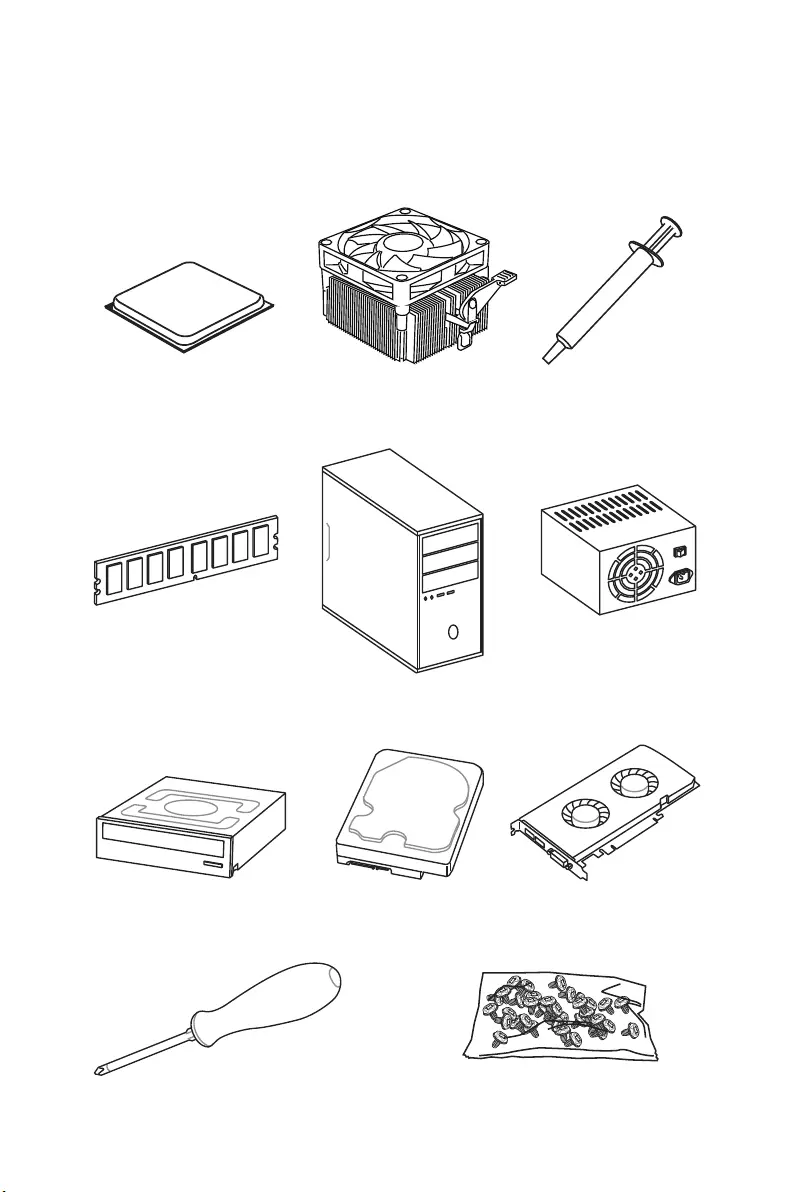
AMD® AM3/ AM3+ CPU
DDR3 Memory
Graphics Card
SATA Hard Disk Drive
SATA DVD Drive
A Package of Screws
Phillips Screwdriver
Chassis
Power Supply Unit
CPU Fan Thermal Paste
Quick Start
Preparing Tools and Components
4Quick Start
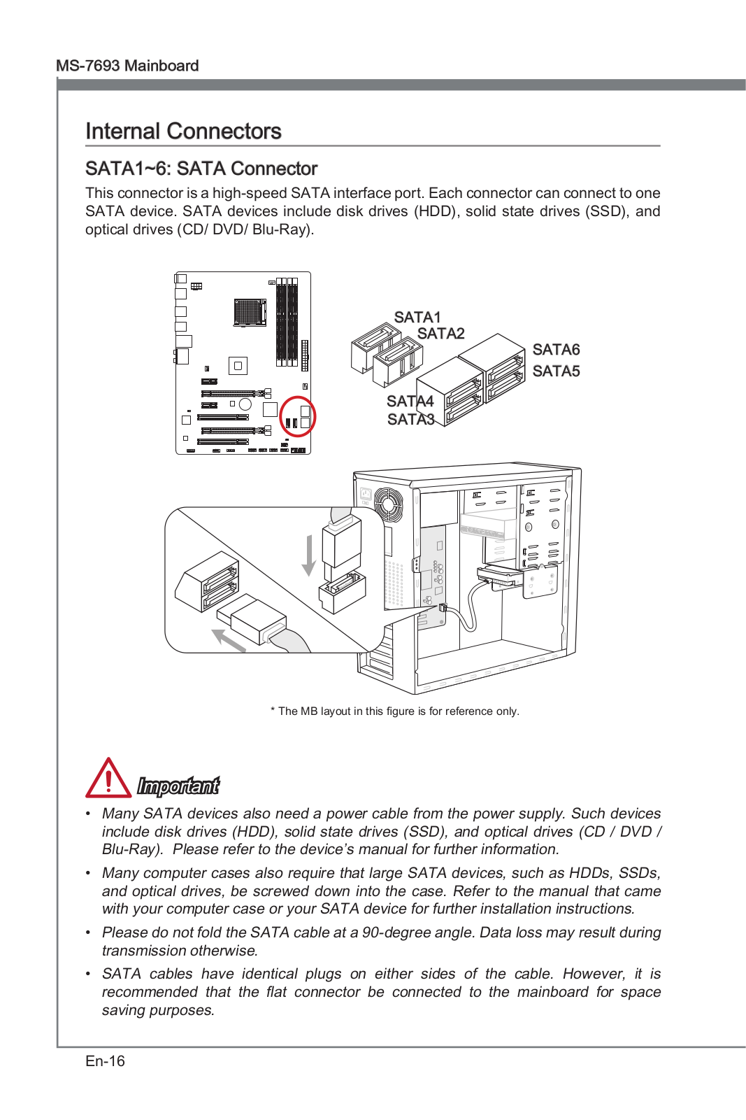
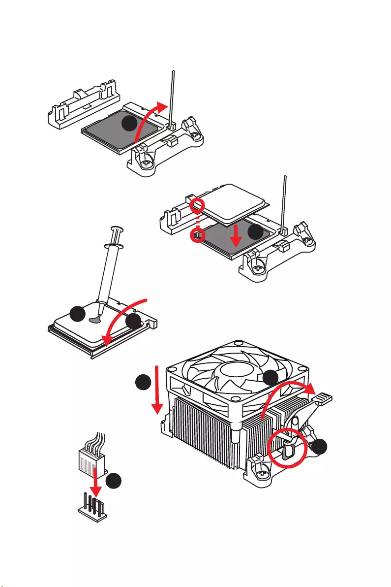
Installing a Processor
1
2
3
6
4
57
8
5
Quick Start
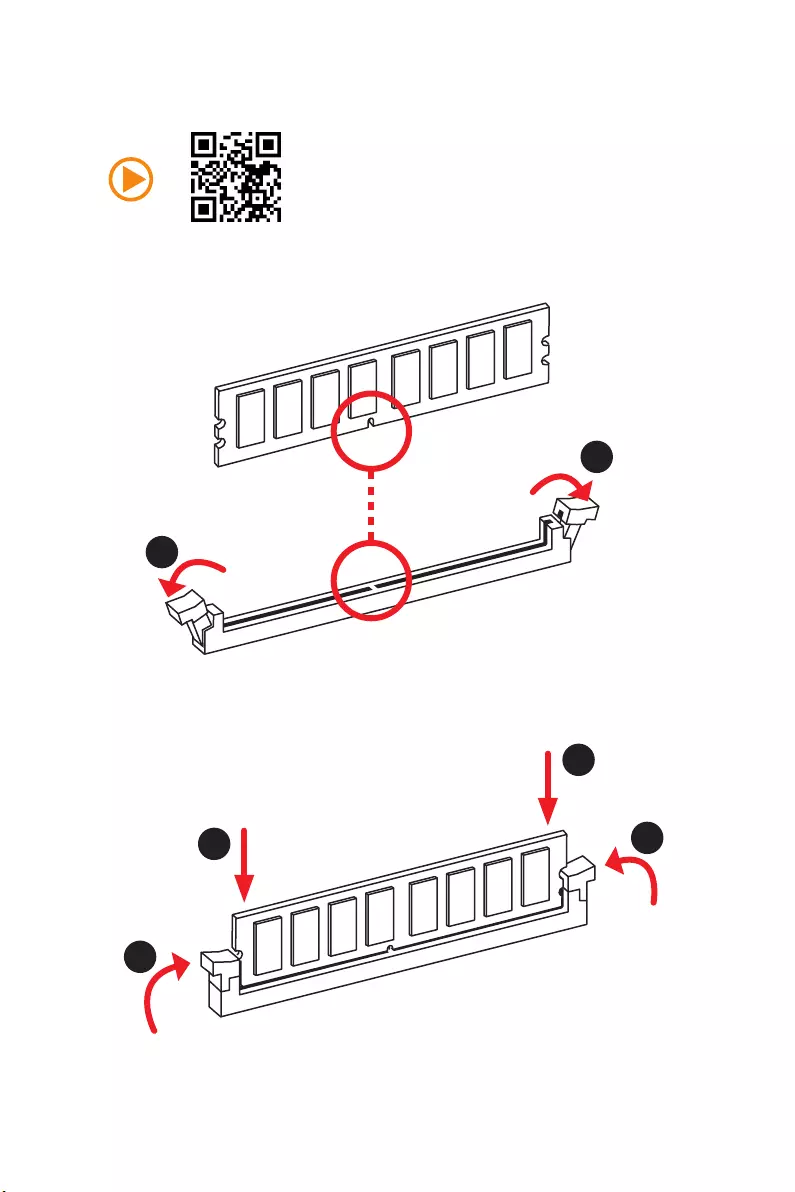
1
1
2
2
3
3
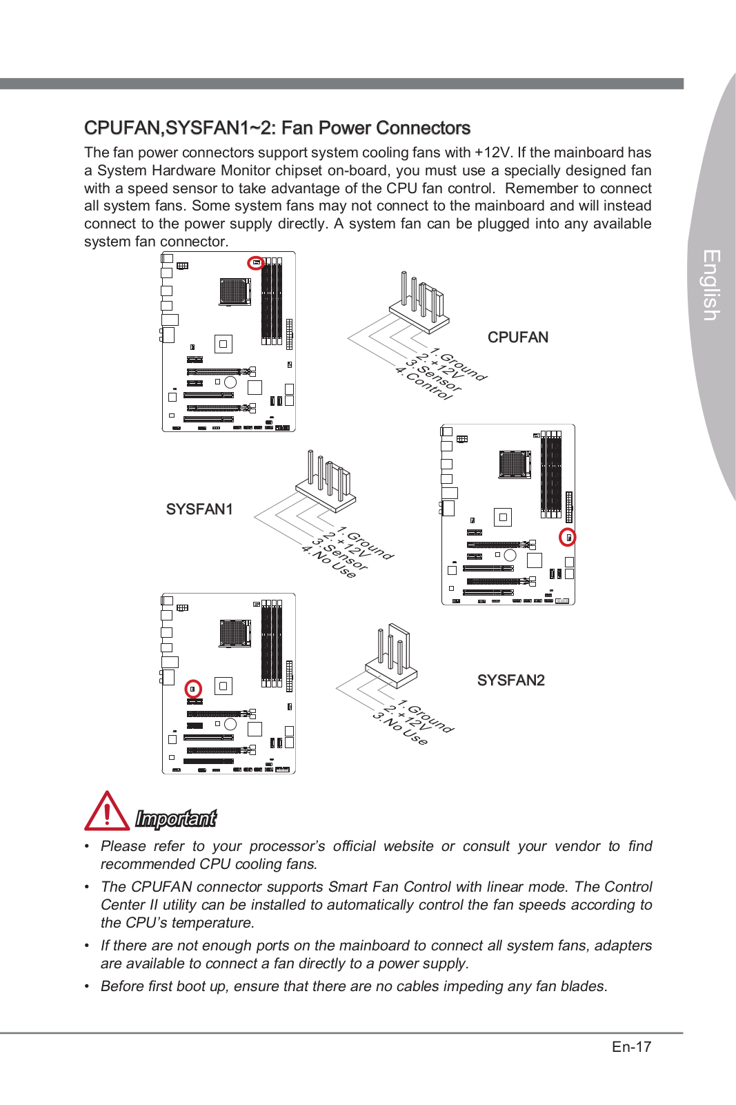
Installing DDR3 memory
6Quick Start
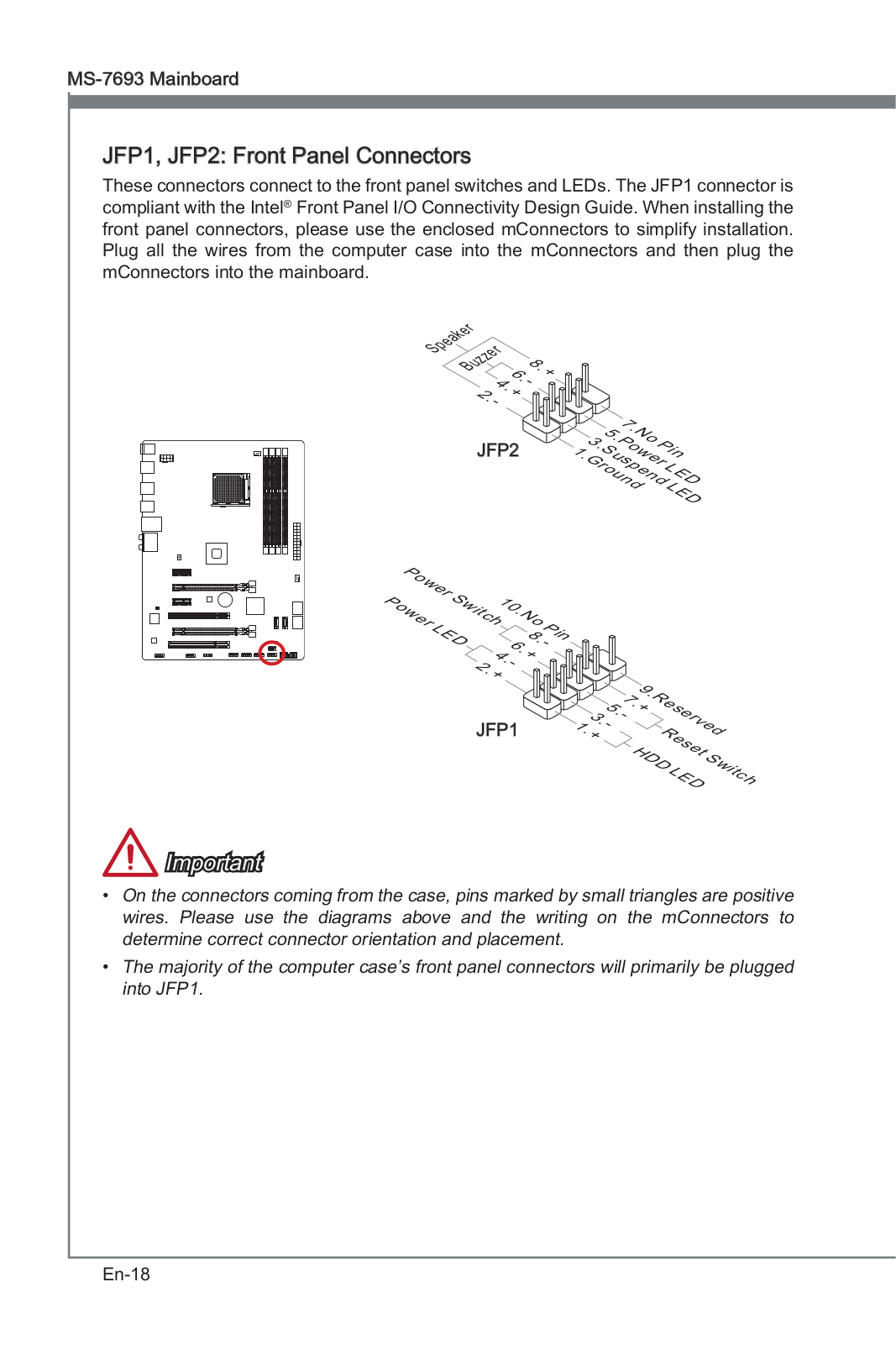
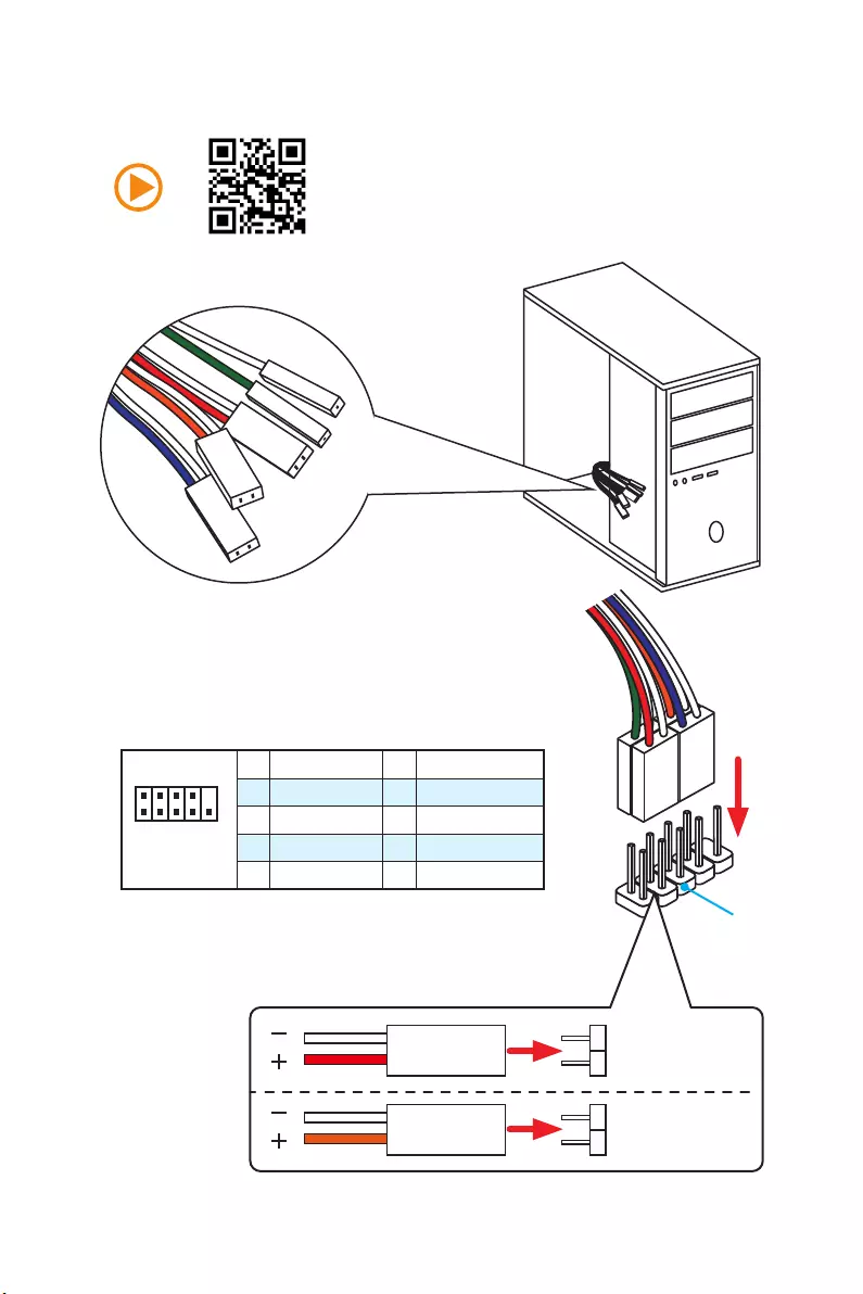
Connecting the Front Panel Header
1
2 10
9
JFP1
1 HDD LED + 2 Power LED +
3 HDD LED — 4 Power LED —
5 Reset Switch 6 Power Switch
7 Reset Switch 8 Power Switch
9 Reserved 10 No Pin
RESET SW
POWER SW
POWER LED+
POWER LED-
HDD LED
HDD LED
RESET SW
JFP1
HDD LED HDD LED —
HDD LED +
POWER LED —
POWER LED +
POWER LED
7
Quick Start
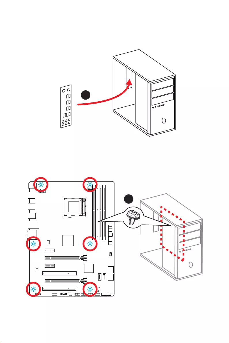
Installing the Motherboard
1
2
8Quick Start
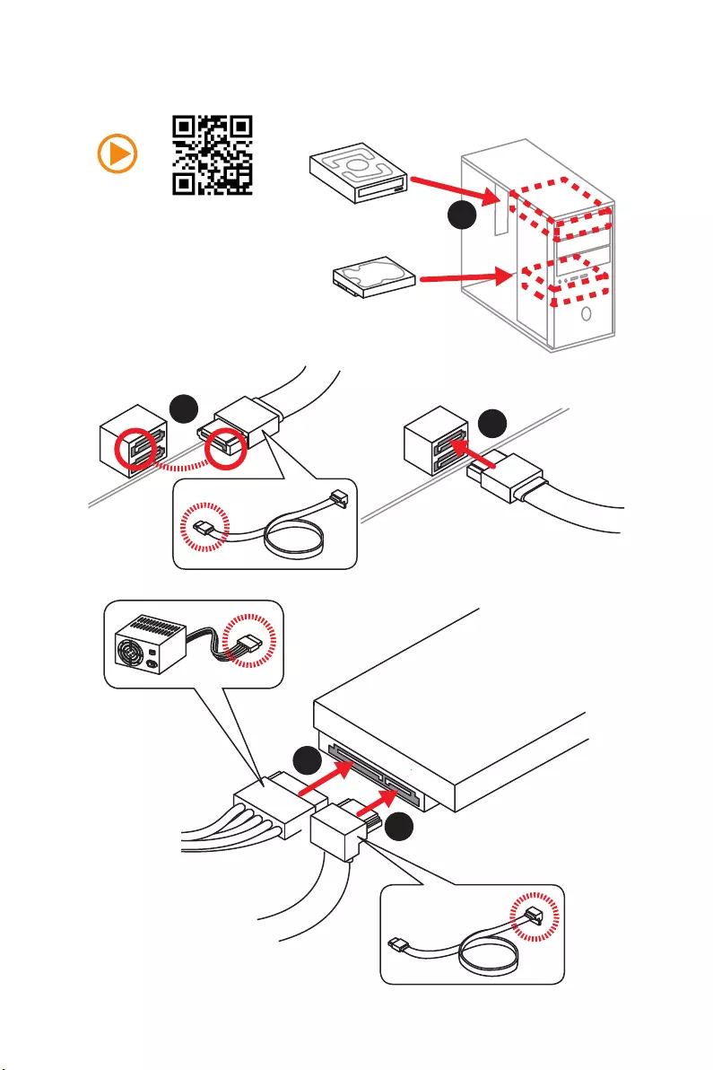
Installing SATA Drives
1
23
4
5
9
Quick Start
1
4
5
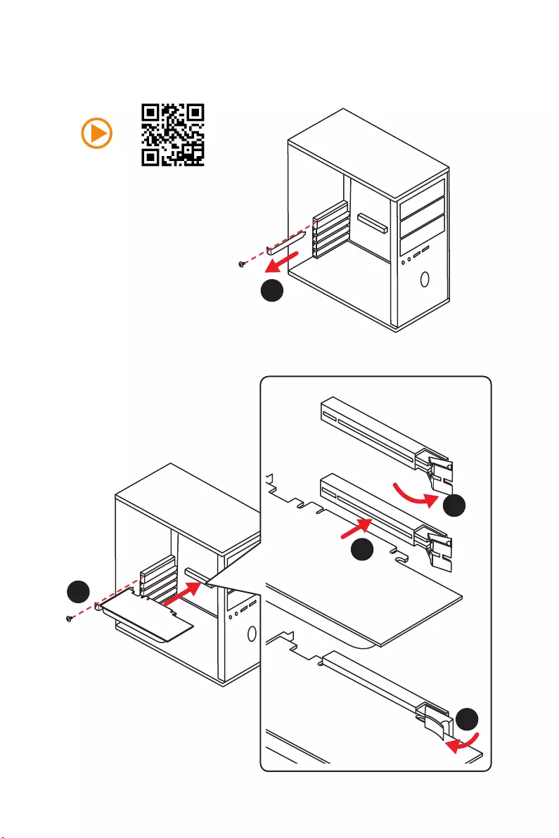
Installing a Graphics Card
2
3
10 Quick Start
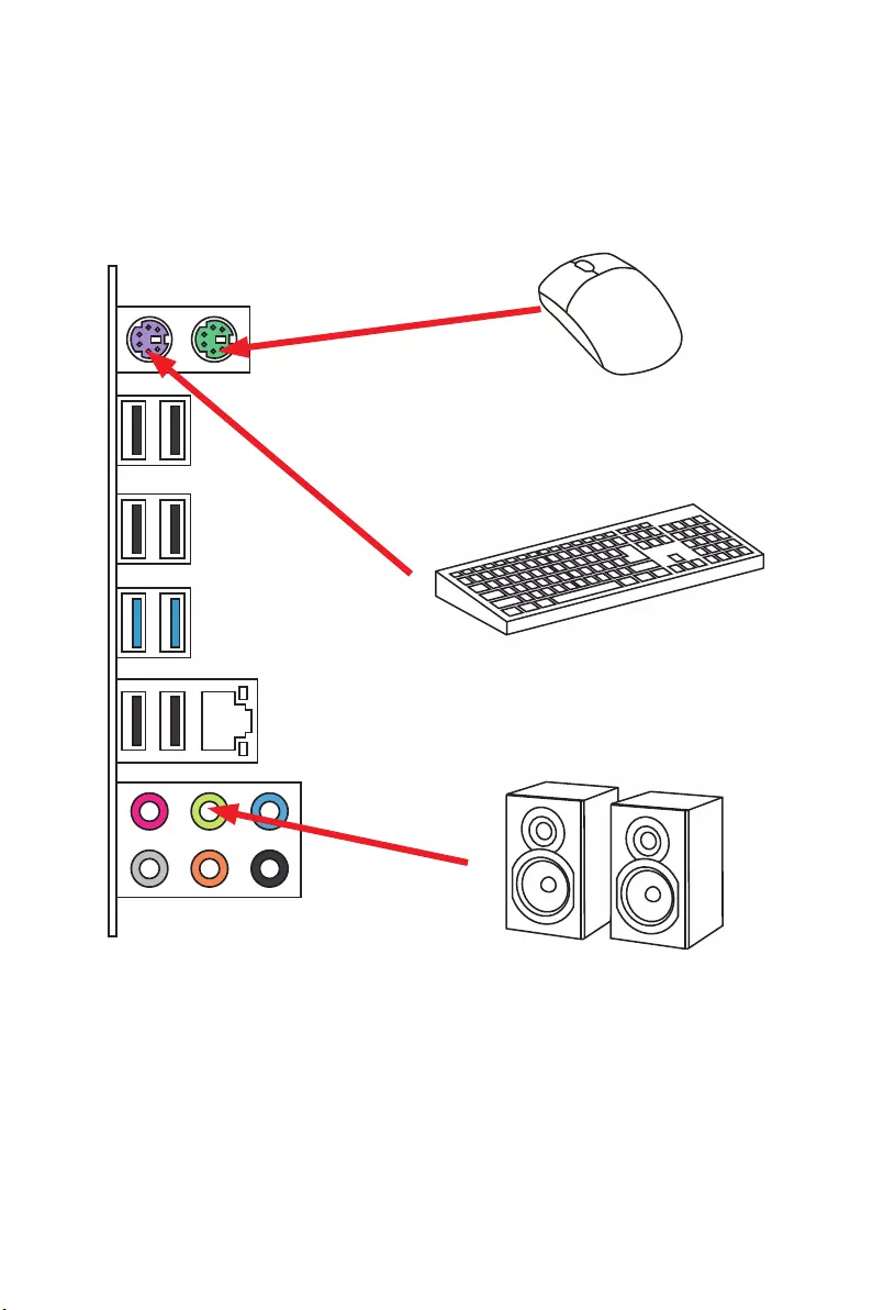
Connecting Peripheral Devices
11
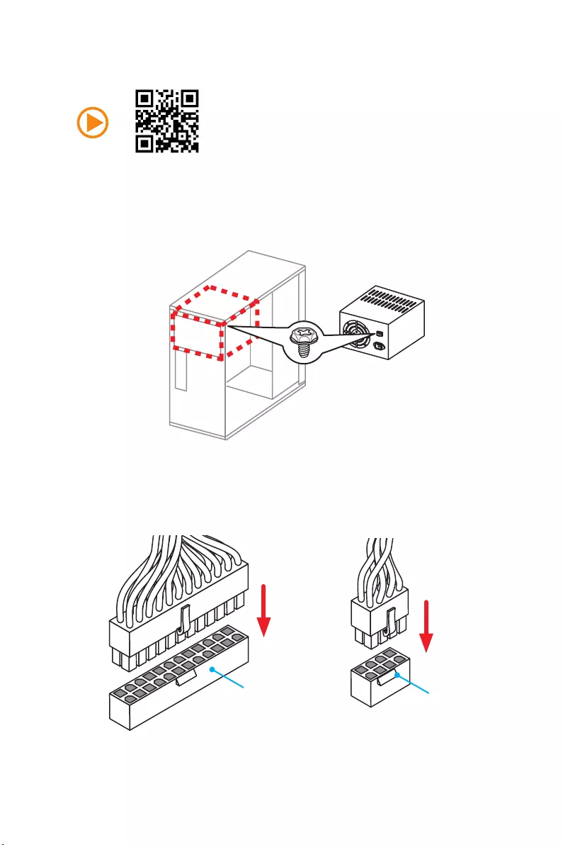
Quick Start
Connecting the Power Connectors
JPWR1 JPWR2
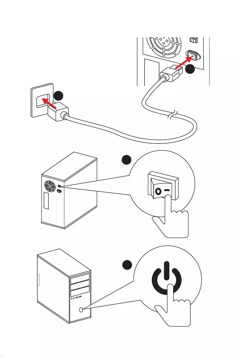
12 Quick Start
Power On
1
4
2
3

13
Contents
Contents
Unpacking ……………………………………………………………………………………………….. 1
Safety Information ……………………………………………………………………………………. 2
Quick Start ………………………………………………………………………………………………. 3
Preparing Tools and Components ……………………………………………………………….. 3
Installing a Processor ………………………………………………………………………………… 4
Installing DDR3 memory ……………………………………………………………………………. 5
Connecting the Front Panel Header …………………………………………………………….. 6
Installing the Motherboard …………………………………………………………………………. 7
Installing SATA Drives………………………………………………………………………………… 8
Installing a Graphics Card ………………………………………………………………………….. 9
Connecting Peripheral Devices …………………………………………………………………. 10
Connecting the Power Connectors …………………………………………………………….. 11
Power On………………………………………………………………………………………………… 12
Specifications …………………………………………………………………………………………. 15
Rear I/O Panel ……………………………………………………………………………………….. 17
LAN Port LED Status Table……………………………………………………………………….. 17
Audio Ports Configuration ………………………………………………………………………… 17
Realtek HD Audio Manager ………………………………………………………………………. 18
Overview of Components ………………………………………………………………………… 20
CPU Socket …………………………………………………………………………………………….. 22
DIMM Slots ……………………………………………………………………………………………… 23
PCI_E1~4 & PCI1~2: PCIe & PCI Expansion Slots ……………………………………….. 24
JAUD1: Front Audio Connector …………………………………………………………………. 25
SATA1~6: SATA 6Gb/s Connectors …………………………………………………………….. 25
JPWR1~2: Power Connectors ……………………………………………………………………. 26
JUSB1~3: USB 2.0 Connectors ………………………………………………………………….. 27
JUSB4: USB 3.1 Gen1 Connector ………………………………………………………………. 27
JFP1, JFP2: Front Panel Connectors …………………………………………………………. 28
JTPM1: TPM Module Connector ………………………………………………………………… 28
JCI1: Chassis Intrusion Connector …………………………………………………………….. 29
JCOM1: Serial Port Connector ………………………………………………………………….. 29
CPUFAN, SYSFAN1~3: Fan Connectors ………………………………………………………. 30
JBAT1: Clear CMOS (Reset BIOS) Jumper ………………………………………………….. 31
BIOS Setup …………………………………………………………………………………………….. 32
Entering BIOS Setup ………………………………………………………………………………… 32
Resetting BIOS ………………………………………………………………………………………… 33

14 Contents
Updating BIOS …………………………………………………………………………………………. 33
Overview ………………………………………………………………………………………………… 34
SETTINGS ……………………………………………………………………………………………….. 35
Advanced ………………………………………………………………………………………………… 35
Boot ……………………………………………………………………………………………………….. 40
Security ………………………………………………………………………………………………….. 40
Save & Exit ……………………………………………………………………………………………… 41
OC ………………………………………………………………………………………………………….. 42
M-FLASH ……………………………………………………………………………………………….. 46
OC PROFILE ……………………………………………………………………………………………. 47
HARDWARE MONITOR ……………………………………………………………………………… 48
Software Description ………………………………………………………………………………. 49
Installing Drivers …………………………………………………………………………………….. 49
Installing Utilities ……………………………………………………………………………………. 49
COMMAND CENTER ………………………………………………………………………………… 50
LIVE UPDATE 6 ………………………………………………………………………………………… 54
NETWORK GENIE ……………………………………………………………………………………. 56
RAID Configuration …………………………………………………………………………………. 58
Using AMD® RAID Option ROM utility …………………………………………………………. 58
Troubleshooting …………………………………………………………………………………….. 62
Regulatory Notices …………………………………………………………………………………. 63
15
Specifications
Specifications
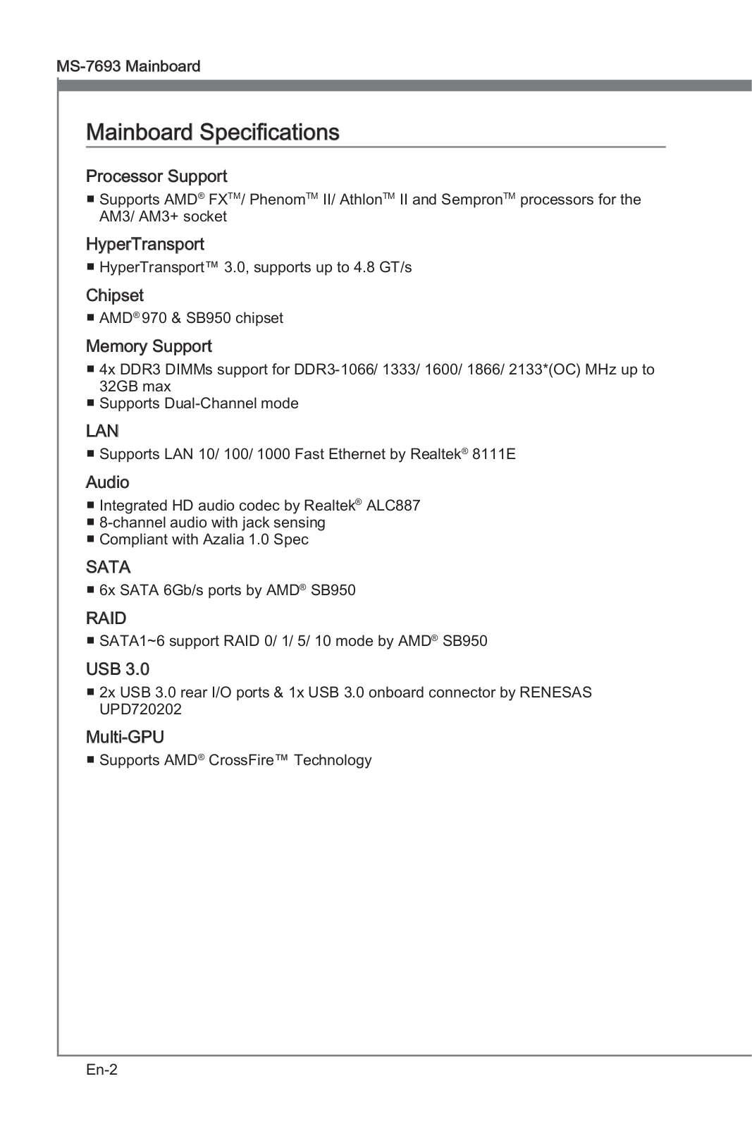
CPU Supports AMD® FX™/ Phenom™/ Athlon™II/ Sempron™ proces-
sors for Socket AM3/ AM3+
Chipset AMD® 970 & SB950 Chipset
Memory
y4x DDR3 memory slots, support up to 32GB
Supports DDR3 1066/ 1333/ 1600/ 1866/ 2133(OC) MHz
yDual channel memory architecture
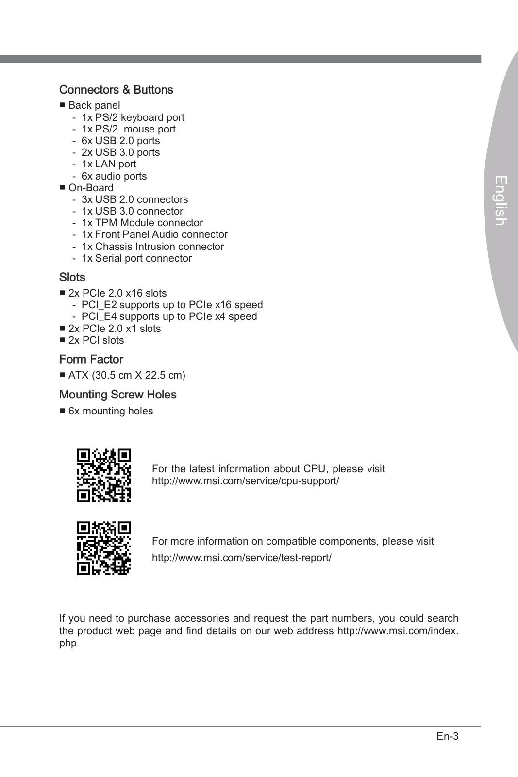
Expansion Slots
y2x PCIe 2.0 x16 slots (support x16/ x4 mode)
y2x PCIe 2.0 x1 slots
y2x PCI slots
Multi-GPU ySupports 2-Way AMD® CrossFire™ Technology
Storage
AMD® SB950 Chipset
y6x SATA 6Gb/s ports
Supports RAID 0, RAID 1, RAID 5 and RAID 10 for SATA
storage devices
USB
yASMedia® ASM1143 Chipset
2x USB 3.1 Gen2 (SuperSpeed USB 10Gbps) ports on the
back panel
yASMedia® ASM1042AE Chipset
2x USB 3.1 Gen1 (SuperSpeed USB) ports available
through the internal USB 3.1 Gen1 connector
yAMD® SB950 Chipset
12x USB 2.0 (High-speed USB) ports (6 ports on the
back panel, 6 ports available through the internal USB
connector)
Audio yRealtek® ALC887 Codec
y7.1-Channel High Definition Audio
LAN 1x Realtek® 8111E Gigabit LAN controller
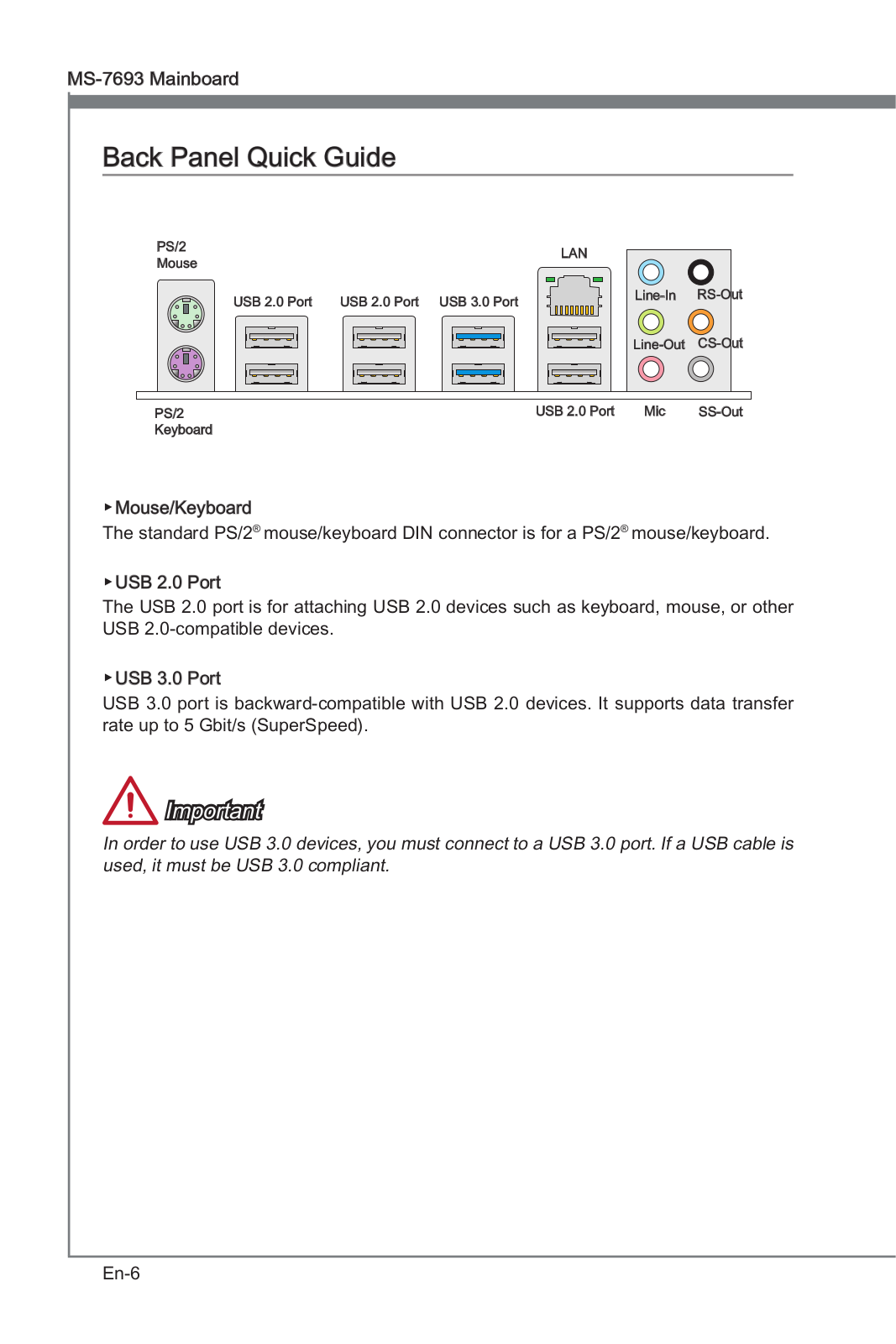
Back Panel
Connectors
y1x PS/2 mouse port
y1x PS/2 keyboard port
y6x USB 2.0 ports
y2x USB 3.1 Gen2 ports
y1x LAN (RJ45) port
y6x audio jacks
Continued on next page

16 Specifications
Continued from previous page
Internal Connectors
y1x 24-pin ATX main power connector
y1x 8-pin ATX 12V power connector
y6x SATA 6Gb/s connectors
y3x USB 2.0 connectors (supports additional 6 USB 2.0
ports)
y1x USB 3.1 Gen1 connector (supports additional 2 USB 3.1
Gen1 ports)
y1x 4-pin CPU fan connector
y2x 4-pin system fan connectors
y1x 3-pin system fan connector
y1x Front panel audio connector
y2x Front panel connectors
y1x TPM module connector
y1x Chassis Intrusion connector
y1x Serial port connector
y1x Clear CMOS jumper
I/O Controller FINTEK F71889ED Controller Chip
Form Factor yATX Form Factor
y12 in. x 8.9 in. (30.5 cm x 22.5 cm)
Software
yDrivers
yCOMMAND CENTER
yLIVE UPDATE 6
yNETWORK GENIE
yFAST BOOT
ySUPER CHARGER
yNorton™ Security
yGoogle Chrome™ ,Google Toolbar, Google Drive
17
Rear I/O Panel
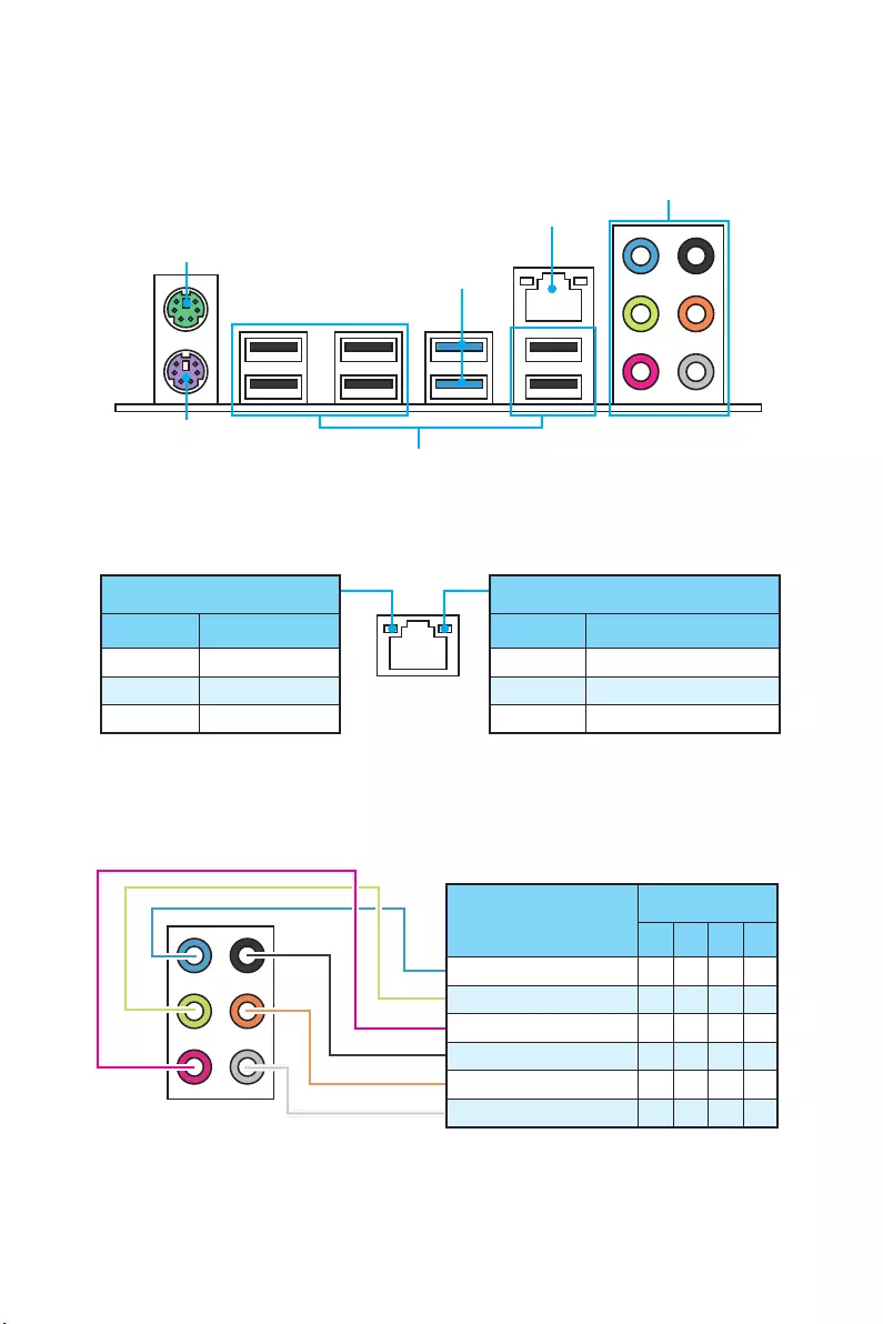
Rear I/O Panel
PS/2 Mouse
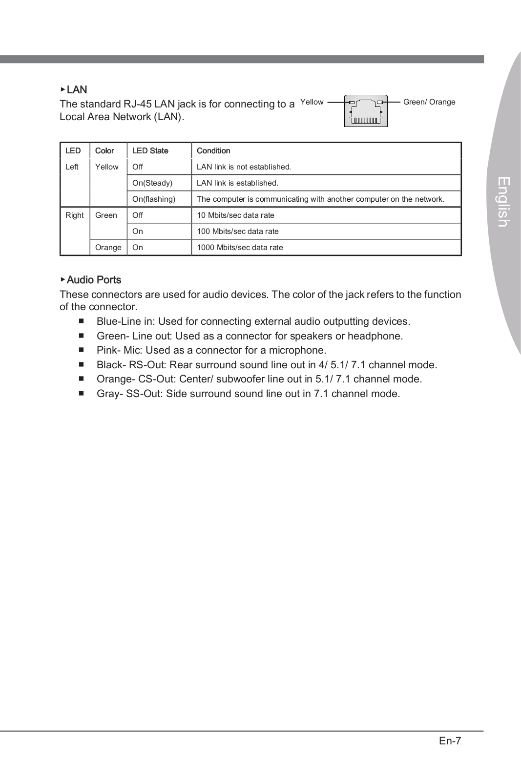
LAN
Audio Ports
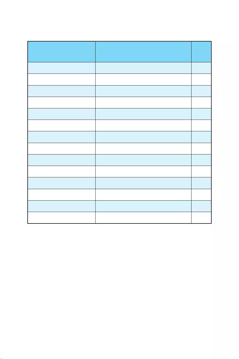
Link/ Activity LED
Status Description
Off No link
Yellow Linked
Blinking Data activity
Speed LED
Status Description
Off 10 Mbps connection
Green 100 Mbps connection
Orange 1 Gbps connection
LAN Port LED Status Table
Audio Ports Configuration
USB 3.1 Gen2
USB 2.0
Audio Ports Channel
2468
Line In
Line-Out/ Front Speak Out ●●●●
Mic In
Rear Speaker Out ●●●
Center/ Subwoofer Out ● ●
Side Speaker Out ●
(●: connected, Blank: empty)
PS/2 Keyboard
18 Rear I/O Panel
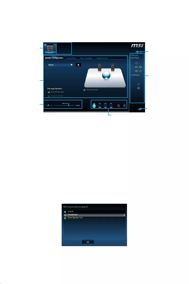
Realtek HD Audio Manager
After installing the Realtek HD Audio driver, the Realtek HD Audio Manager icon will
appear in the system tray. Double click on the icon to launch.
Jack Status
Device
Selection
Connector
Strings
Profiles
Main Volume
Application
Enhancement
Advanced
Settings
yDevice Selection — allows you to select a audio output source to change the related
options. The check sign indicates the devices as default.
yApplication Enhancement — the array of options will provide you a complete
guidance of anticipated sound effect for both output and input device.
yMain Volume — controls the volume or balance the right/left side of the speakers
that you plugged in front or rear panel by adjust the bar.
yProfiles — toggles between profiles.
yAdvanced Settings — provides the mechanism to deal with 2 independent audio
streams.
yJack Status — depicts all render and capture devices currently connected with your
computer.
yConnector Settings — configures the connection settings.
Auto popup dialog
When you plug into a device at an audio jack, a dialogue window will pop up asking you
which device is current connected.
Each jack corresponds to its default setting as shown on the next page.
19
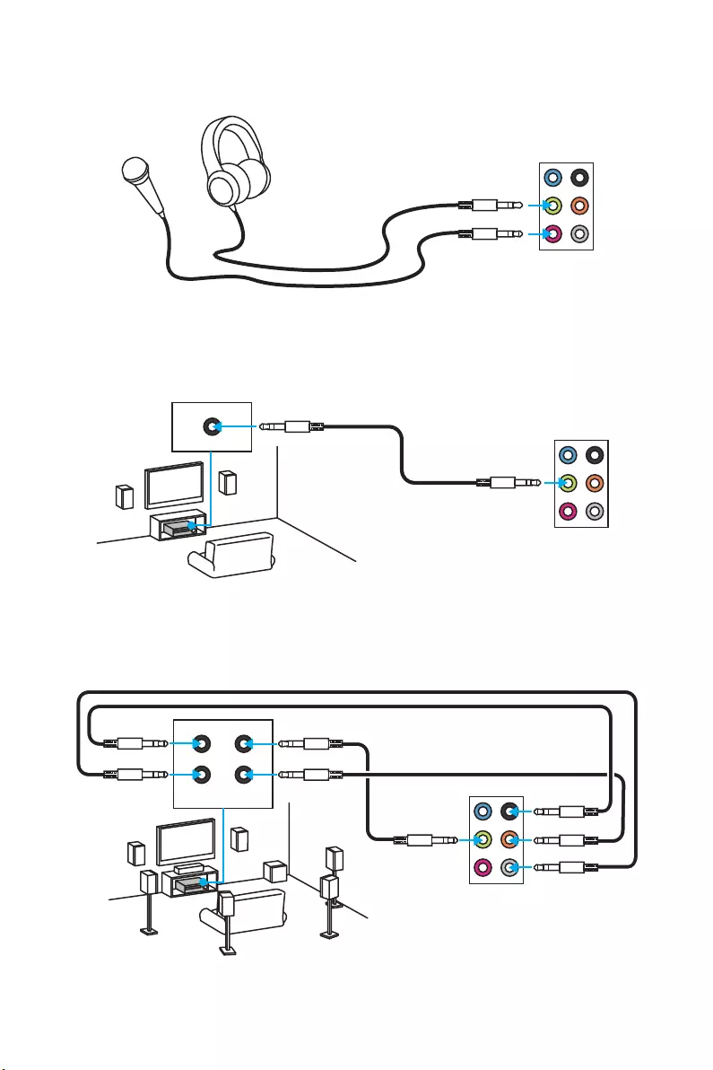
Rear I/O Panel
Audio jacks to headphone and microphone diagram
Audio jacks to stereo speakers diagram
Audio jacks to 7.1-channel speakers diagram
AUDIO INPUT
AUDIO INPUT
Rear Front
Side Center/
Subwoofer
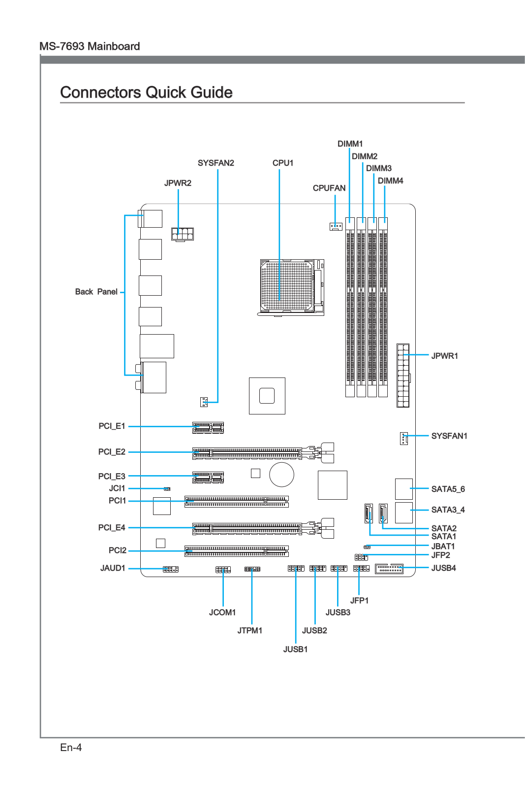
20 Overview of Components
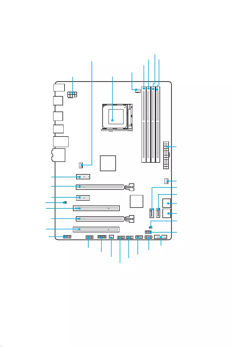
Overview of Components
CPUFAN
PCI_E1
PCI_E2
PCI_E3
PCI1
CPU Socket
JPWR2
DIMM1
SYSFAN1 DIMM2
DIMM3
DIMM4
JUSB3
SYSFAN2
JFP1
JFP2
JTPM1
JPWR1
JBAT1
SATA1
SATA5_6
SATA3_4
JUSB1
JUSB2
JUSB4
JCOM1
PCI_E4
PCI2
SYSFAN3
SATA2
JCI1
JAUD1
21
Overview of Components
Component Contents
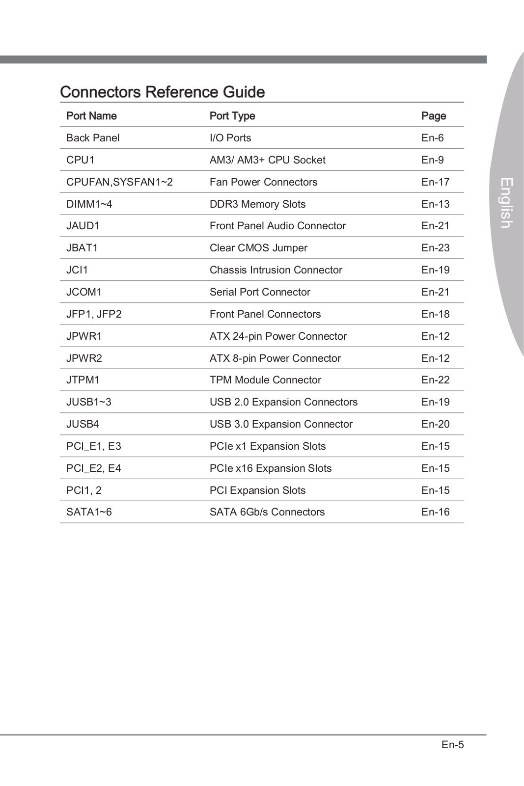
Port Name Port Type Page
CPUFAN, SYSFAN1~3 Fan Connectors 30
CPU Socket AM3/ AM3+ CPU Socket 22
DIMM1~4 DIMM Slots 23
JAUD1 Front Audio Connector 25
JBAT1 Clear CMOS (Reset BIOS) Jumper 31
JCI1 Chassis Intrusion Connector 29
JCOM1 Serial Port Connector 29
JFP1, JFP2 Front Panel Connectors 28
JPWR1~2 Power Connectors 26
JTPM1 TPM Module Connector 28
JUSB1~3 USB 2.0 Connectors 27
JUSB4 USB 3.1 Gen1 Connector 27
PCI_E1~E4 & PCI1~2 PCIe & PCI Expansion Slots 24
SATA1~6 SATA 6Gb/s Connectors 25

22 Overview of Components
CPU Socket
Introduction to AM3/ AM3+ CPU
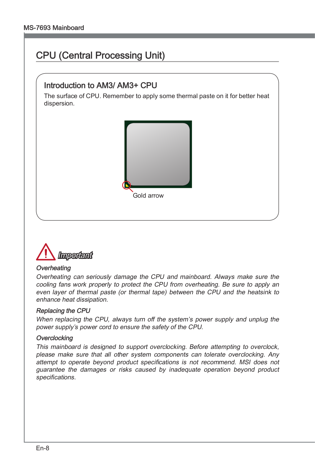
The surface of the CPU has a golden
triangle to assist in correctly lining up
the CPU for motherboard placement.
The golden triangle is the Pin 1 indicator.
Important
y
Always unplug the power cord from the power outlet before installing or removing
the CPU.
y
When installing a CPU, always remember to install a CPU heatsink. A CPU heatsink
is necessary to prevent overheating and maintain system stability.
y
Confirm that the CPU heatsink has formed a tight seal with the CPU before booting
your system.
y
Overheating can seriously damage the CPU and motherboard. Always make sure
the cooling fans work properly to protect the CPU from overheating. Be sure to
apply an even layer of thermal paste (or thermal tape) between the CPU and the
heatsink to enhance heat dissipation.
y
If you purchased a separate CPU and heatsink/ cooler, Please refer to the
documentation in the heatsink/ cooler package for more details about installation.
y
This motherboard is designed to support overclocking. Before attempting to
overclock, please make sure that all other system components can tolerate
overclocking. Any attempt to operate beyond product specifications is not
recommended. MSI
®
does not guarantee the damages or risks caused by
inadequate operation beyond product specifications.
y
While disconnecting the safety hook from the fixed bolt. It is necessary to keep an
eye on your fingers, because once the safely hook is disconnected from the fixed
bolt, the fixed lever will spring back instantly.
23
Overview of Components
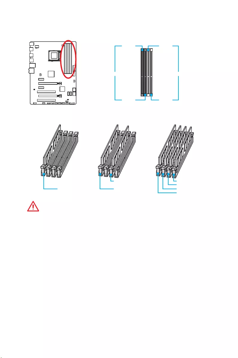
DIMM Slots
DIMM1 DIMM3
Channel A Channel B
DIMM2 DIMM4
Memory module installation recommendation
DIMM3 DIMM4
DIMM3
DIMM1 DIMM1 DIMM2
DIMM1
Important
y
Always insert memory modules in the DIMM1 slot first.
y
Due to chipset resource usage, the available capacity of memory will be a little less
than the amount of installed.
y
Please note that the maximum capacity of addressable memory is 4GB or less
for 32-bit Windows OS due to the memory address limitation. Therefore, we
recommended that you to install 64-bit Windows OS if you want to install more than
4GB memory on the motherboard.
y
Some memory may operate at a lower frequency than the marked value when
overclocking due to the memory frequency operates dependent on its Serial
Presence Detect (SPD).
y
It is recommended to use a more efficient memory cooling system for full DIMMs
installation or overclocking.
y
The stability and compatibility of installed memory module depend on installed CPU
and devices when overclocking.
24 Overview of Components
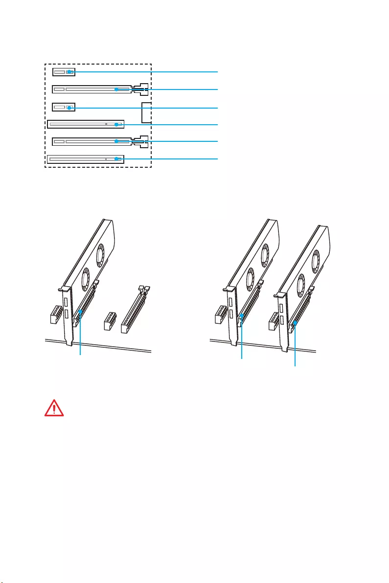
PCI_E1~E4 & PCI1~2: PCIe & PCI Expansion Slots
PCI_E1: PCIe 2.0 x1 slot
PCI_E2: PCIe 2.0 x16 slot
PCI_E3: PCIe 2.0 x1 slot
PCI1: PCI slot
PCI_E4: PCIe 2.0 x4 slot
PCI2: PCI slot
x16 x16 x4
Multiple graphics cards installation recommendation
Important
y
For a single PCIe x16 expansion card installation with optimum performance, using
the PCI_E2 slot is recommended.
y
When adding or removing expansion cards, always turn off the power supply and
unplug the power supply power cable from the power outlet. Read the expansion
card’s documentation to check for any necessary additional hardware or software
changes.
25
Overview of Components
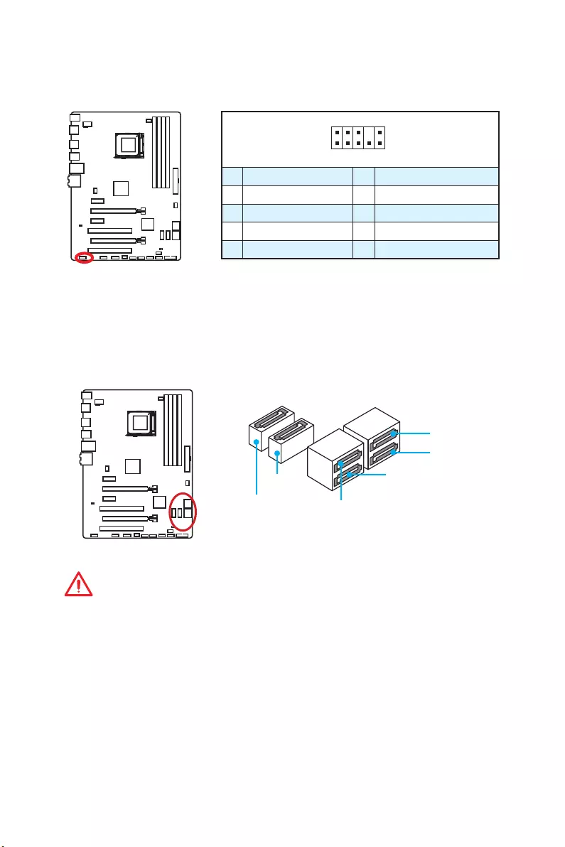
SATA1~6: SATA 6Gb/s Connectors
These connectors are SATA 6Gb/s interface ports. Each connector can connect to one
SATA device.
SATA1
SATA2 SATA3
SATA5
SATA6
SATA4
Important
y
Please do not fold the SATA cable at a 90-degree angle. Data loss may result during
transmission otherwise.
y
SATA cable has identical plugs on either sides of the cable. However, it is
recommended that the flat connector be connected to the motherboard for space
saving purposes.
JAUD1: Front Audio Connector
This connector allows you to connect audio jacks on the front panel.
1
2 10
9
1 MIC L 2 Ground
3 MIC R 4 NC
5 Head Phone R 6 MIC Detection
7 SENSE_SEND 8 No Pin
9 Head Phone L 10 Head Phone Detection
26 Overview of Components
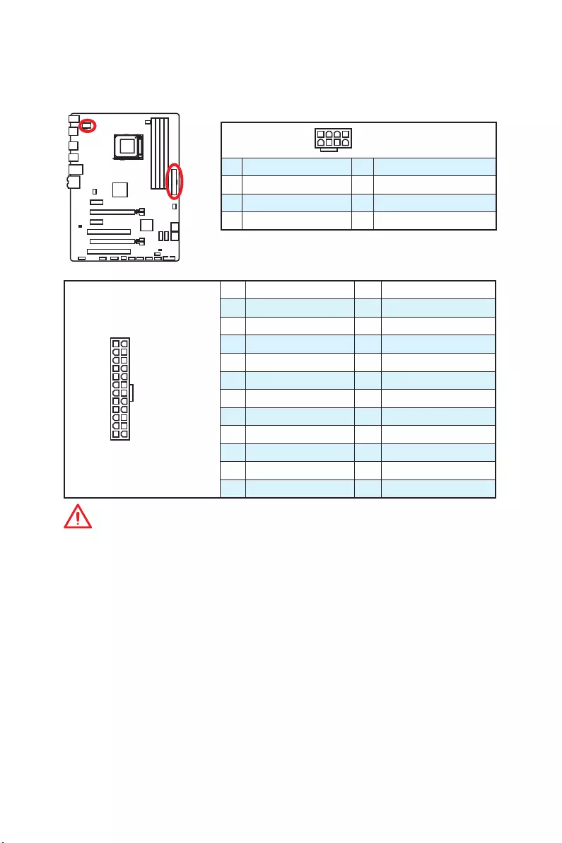
JPWR1~2: Power Connectors
These connectors allow you to connect an ATX power supply.
24
131
12
JPWR1
1 +3.3V 13 +3.3V
2 +3.3V 14 -12V
3 Ground 15 Ground
4 +5V 16 PS-ON#
5 Ground 17 Ground
6 +5V 18 Ground
7 Ground 19 Ground
8 PWR OK 20 Res
9 5VSB 21 +5V
10 +12V 22 +5V
11 +12V 23 +5V
12 +3.3V 24 Ground
541 8JPWR2
1 Ground 5 +12V
2 Ground 6 +12V
3 Ground 7 +12V
4 Ground 8 +12V
Important
Make sure that all the power cables are securely connected to a proper ATX power
supply to ensure stable operation of the motherboard.
27
Overview of Components
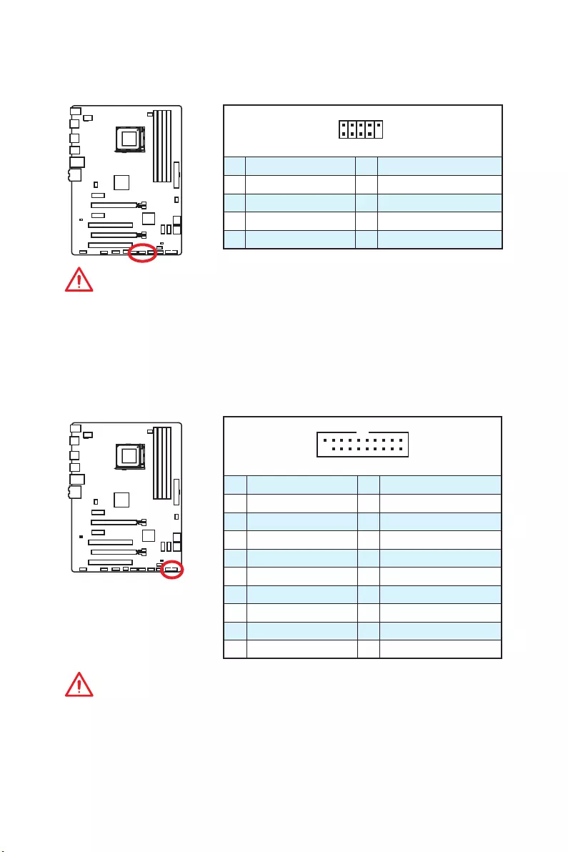
JUSB4: USB 3.1 Gen1 Connector
This connector allows you to connect USB 3.1 Gen1 ports on the front panel.
1 10
1120
1Power 11 USB2.0+
2 USB3_RX_DN 12 USB2.0-
3 USB3_RX_DP 13 Ground
4 Ground 14 USB3_TX_C_DP
5 USB3_TX_C_DN 15 USB3_TX_C_DN
6 USB3_TX_C_DP 16 Ground
7 Ground 17 USB3_RX_DP
8 USB2.0- 18 USB3_RX_DN
9 USB2.0+ 19 Power
10 Ground 20 No Pin
Important
Note that the Power and Ground pins must be connected correctly to avoid possible
damage.
JUSB1~3: USB 2.0 Connectors
These connectors allow you to connect USB 2.0 ports on the front panel.
1
2 10
9
1VCC 2VCC
3 USB0- 4 USB1-
5 USB0+ 6 USB1+
7 Ground 8 Ground
9 No Pin 10 NC
Important
y
Note that the VCC and Ground pins must be connected correctly to avoid possible
damage.
y
In order to recharge your iPad,iPhone and iPod through USB ports, please install
MSI
®
SUPER CHARGER utility.
28 Overview of Components
1
2 14
13
1 LPC Clock 2 3V Standby power
3 LPC Reset 4 3.3V Power
5 LPC address & data pin0 6 Serial IRQ
7 LPC address & data pin1 8 5V Power
9 LPC address & data pin2 10 No Pin
11 LPC address & data pin3 12 Ground
13 LPC Frame 14 Ground
JTPM1: TPM Module Connector
This connector is for TPM (Trusted Platform Module). Please refer to the TPM security
platform manual for more details and usages.
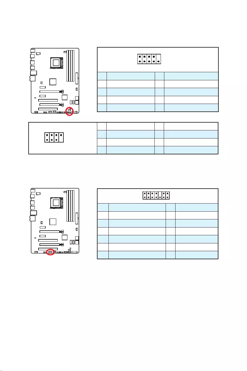
JFP1, JFP2: Front Panel Connectors
These connectors connect to the switches and LEDs on the front panel.
1
2 10
9
JFP1
1 HDD LED + 2 Power LED +
3 HDD LED — 4 Power LED —
5 Reset Switch 6 Power Switch
7 Reset Switch 8 Power Switch
9 Reserved 10 No Pin
1
2 8
7
JFP2
1 Ground 2 Speaker —
3 Suspend LED 4 Buzzer +
5 Power LED 6 Buzzer —
7 No Pin 8 Speaker +
29
Overview of Components
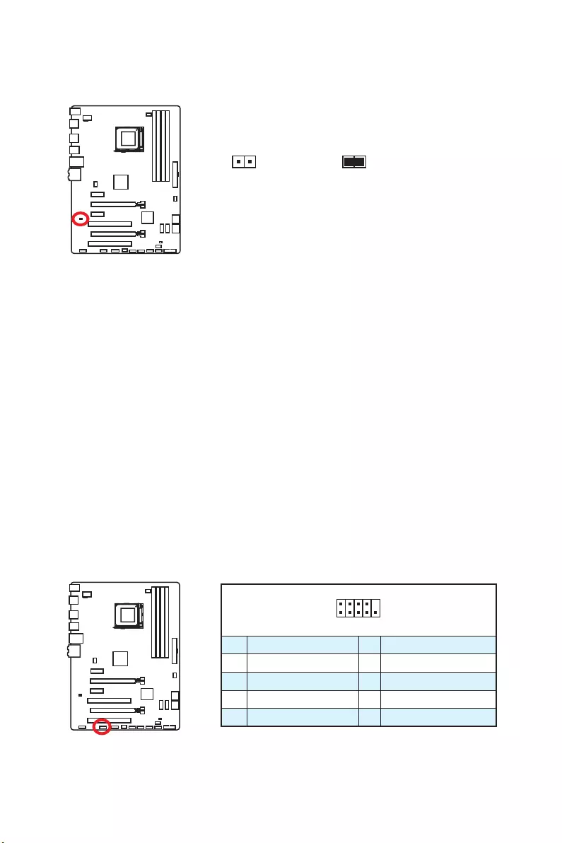
JCI1: Chassis Intrusion Connector
This connector allows you to connect the chassis intrusion switch cable.
Normal
(default)
Trigger the chassis
intrusion event
Using chassis intrusion detector
1. Connect the JCI1 connector to the chassis intrusion switch/ sensor on the chassis.
2. Close the chassis cover.
3. Go to BIOS > SETTINGS > Security > Chassis Intrusion Configuration.
4. Set Chassis Intrusion to Enabled.
5. Press F10 to save and exit and then press the Enter key to select Yes.
6. Once the chassis cover is opened again, a warning message will be displayed on
screen when the computer is turned on.
Resetting the chassis intrusion warning
1. Go to BIOS > SETTINGS > Security > Chassis Intrusion Configuration.
2. Set Chassis Intrusion to Reset.
3. Press F10 to save and exit and then press the Enter key to select Yes.
1
2 10
9
1 DCD 2 SIN
3 SOUT 4 DTR
5 Ground 6 DSR
7 RTS 8 CTS
9 RI 10 No Pin
JCOM1: Serial Port Connector
This connector allows you to connect the optional serial port with bracket.
30 Overview of Components
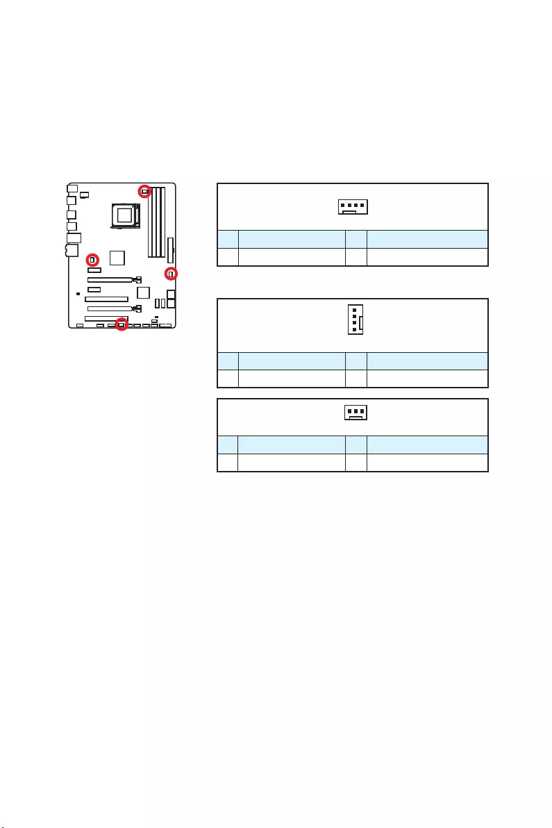
CPUFAN, SYSFAN1~3: Fan Connectors
Fan connectors can be classified as PWM (Pulse Width Modulation) Mode and Voltage
Mode. PWM Mode fan connectors provide constant 12V output and adjust fan speed
with speed control signal. Voltage Mode fan connectors control fan speed by changing
voltage. Therefore, when you plug a 3-pin (Non-PWM) fan to a PWM Mode fan
connector, the fan speed will be always maintained at 100%, and that could be noisy.
1
CPUFAN
1 Ground 2 +12V
3 Sense 4 Speed Control Signal
1
SYSFAN1/ 3
1 Ground 2 +12V
3 Sense 4 NC
PWM Mode fan connector
Voltage Mode fan connector
Controlling the fan speed
There are two ways to manage fan speed. One is to go to BIOS > HARDWARE
MONITOR. The other is to use COMMAND CENTER application.
Both methods offer gradient points of the fan speed that allow you to adjust fan speed
in relation to CPU temperature.
1
SYSFAN2
1 Ground 2 +12V
3 No Use
31
Overview of Components
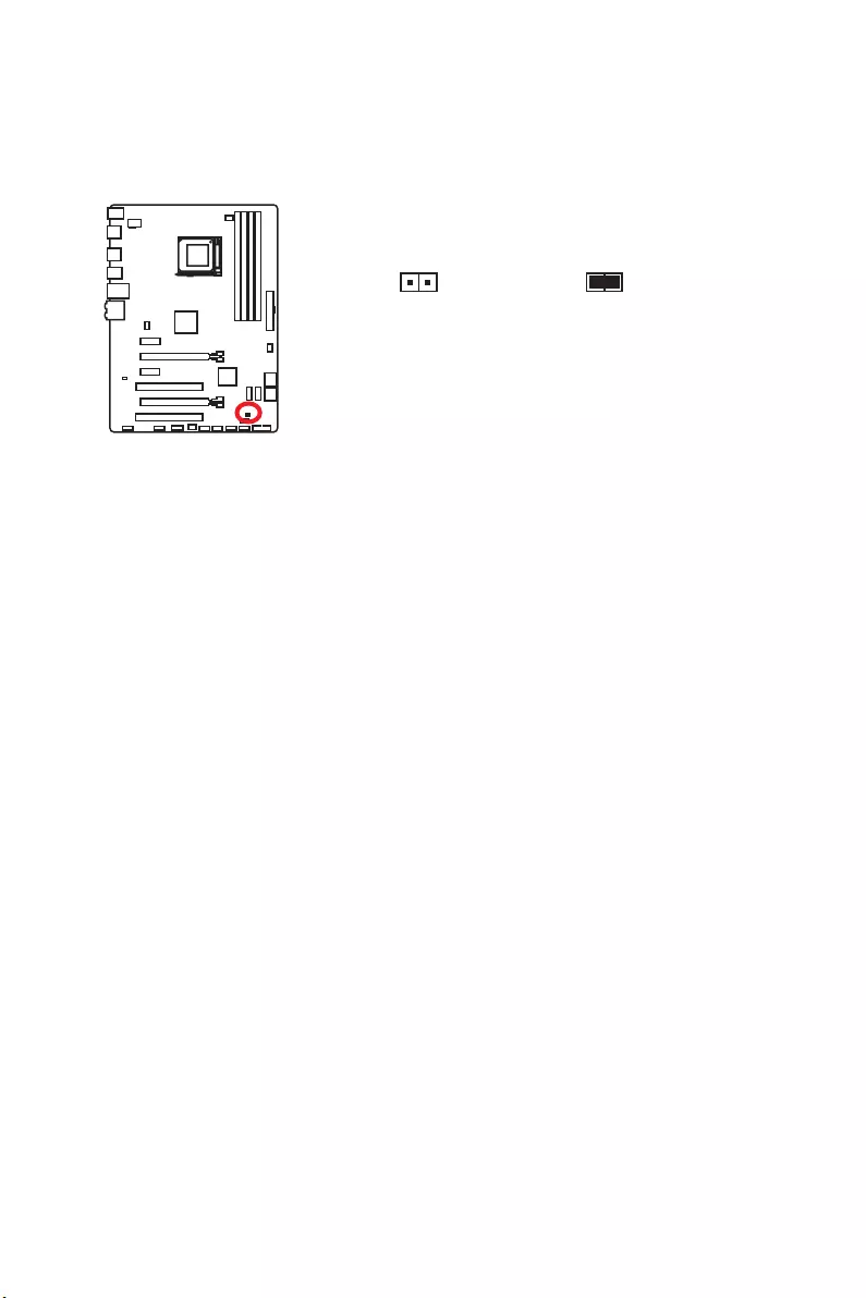
JBAT1: Clear CMOS (Reset BIOS) Jumper
There is CMOS memory onboard that is external powered from a battery located on
the motherboard to save system configuration data. If you want to clear the system
configuration, set the jumper to clear the CMOS memory.
Keep Data
(default)
Clear CMOS/
Reset BIOS
Resetting BIOS to default values
1. Power off the computer and unplug the power cord.
2. Use a jumper cap to short JBAT1 for about 5-10 seconds.
3. Remove the jumper cap from JBAT1.
4. Plug the power cord and power on the computer.

32 BIOS Setup
BIOS Setup
The default settings offer the optimal performance for system stability in normal
conditions. You should always keep the default settings to avoid possible system
damage or failure booting unless you are familiar with BIOS.
Important
y
BIOS items are continuously update for better system performance. Therefore,
the description may be slightly different from the latest BIOS and should be for
reference only. You could also refer to the HELP information panel for BIOS item
description.
y
The pictures in this chapter are for reference only and may vary from the product
you purchased.
Entering BIOS Setup
Please refer the following methods to enter BIOS setup.
yPress Delete key, when the Press DEL key to enter Setup Menu, F11 to enter Boot
Menu message appears on the screen during the boot process.
yUse MSI FAST BOOT application. Click on GO2BIOS button and choose OK. The
system will reboot and enter BIOS setup directly.
Click on GO2BIOS
Function key
Key Function Key Function
F1 General Help F4 Enter CPU Specifications menu
F5 Enter Memory-Z menu F6 Load optimized defaults
F8 Load Overclocking Profile from
USB flash drive F9 Save Overclocking Profile to USB
flash drive
F10 Save Change and Reset F12 Save a screenshot to a FAT/ FAT
32 USB flash drive

33
BIOS Setup
Resetting BIOS
You might need to restore the default BIOS setting to solve certain problems. There are
several ways to reset BIOS:
yGo to BIOS and press F6 to load optimized defaults.
yShort the Clear CMOS jumper on the motherboard.
Important
Please refer to the Clear CMOS jumper section for resetting BIOS.
Updating BIOS
Updating BIOS with M-FLASH
Before updating:
Please download the latest BIOS file that matches your motherboard model from MSI
website. And then save the BIOS file into the USB flash drive.
Updating BIOS:
1. Press Del key to enter the BIOS Setup during POST.
2. Insert the USB flash drive that contains the update file into the computer.
3. Go to BIOS > M-Flash > Update BIOS > Select one file to update BIOS, select a
BIOS file to perform the BIOS update process.
4. After the flashing process is 100% completed, the system will reboot
automatically.
Updating the BIOS with Live Update 6
Before updating:
Make sure the LAN driver is already installed and the internet connection is set
properly.
Updating BIOS:
1. Install and launch MSI LIVE UPDATE 6.
2. Select Manual scan.
3. Check MB BIOS box and click on Scan button.
4. Select the MB BIOS and click on icon to download and install the latest BIOS
file.
5. Click Next and choose In Windows mode. And then click Next and Start to start
updating BIOS.
6. After the flashing process is 100% completed, the system will restart
automatically.
34 BIOS Setup
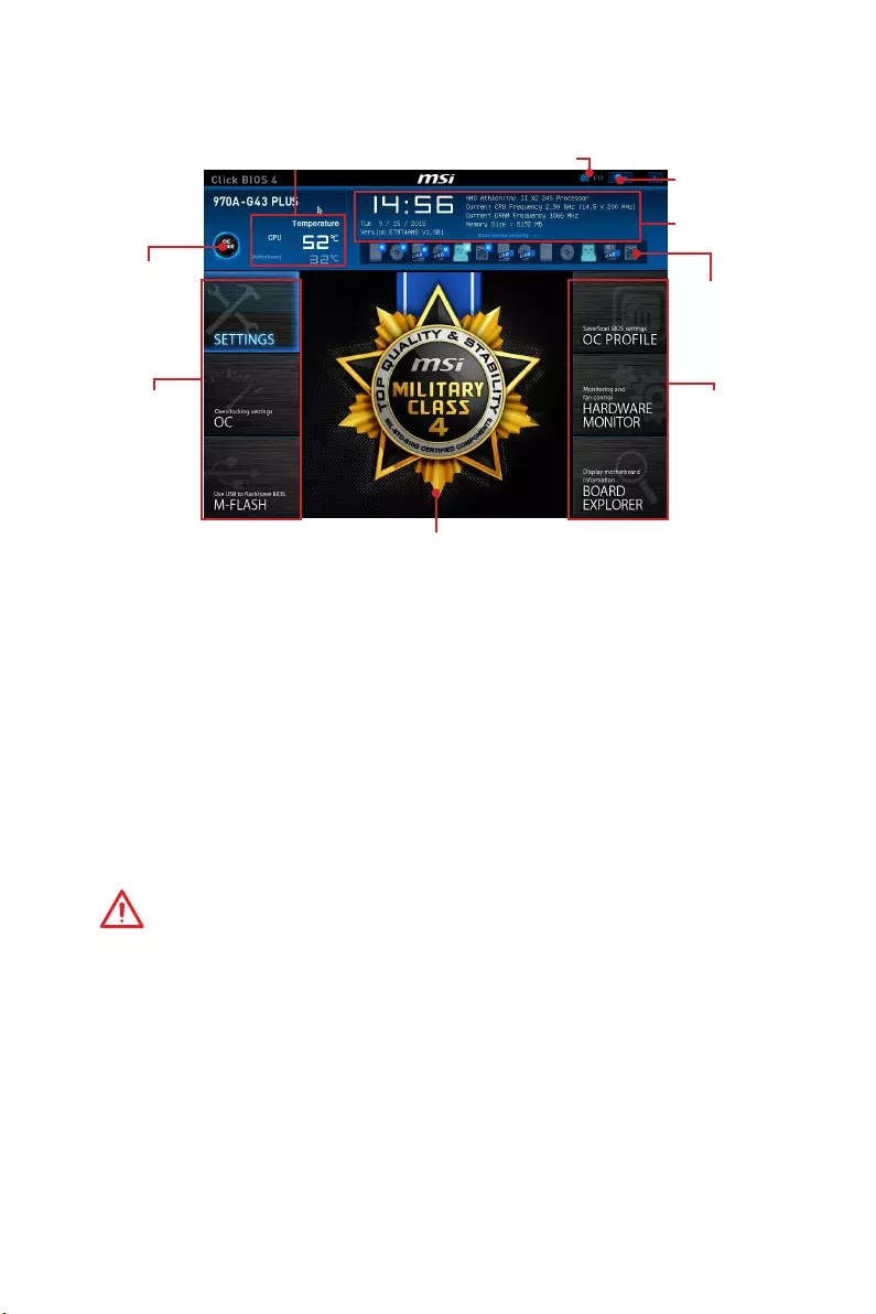
Overview
After entering BIOS, the following screen is displayed.
Temperature
System
information
Boot device
priority bar
BIOS menu
selection
Language
Virtual OC
Genie Button
Screenshot
Menu display
BIOS menu
selection
yBIOS menu selection — the following options are available:
SETTINGS — allows you to specify the parameters for chipset and boot devices.
OC — contains the frequency and voltage adjustments. Increasing the frequency
may get better performance.
M-FLASH — provides the way to update BIOS with a USB flash drive.
OC PROFILE — allows you to manage overclocking profiles.
HARDWARE MONITOR — allows you to set the speeds of fans and monitor voltages
of system.
BOARD EXPLORER — provides the information of installed devices on this
motherboard.
yVirtual OC Genie Button — enables or disables the OC Genie function by clicking on
this button. When enabled, this button will be light. Enabling OC Genie function can
automatically overclock with MSI optimized overclocking profile.
Important
We recommend that you do not to make any modification in OC menu mode and do not
to load defaults after enabling the OC Genie function.
yMenu display — provides BIOS setting items and information to be configured.
yBoot device priority bar — you can move the device icons to change the boot priority.
The boot priority from high to low is left to right.
ySystem Information — shows the time, date, CPU name, CPU frequency, DRAM
frequency, DRAM capacity and the BIOS version.
yLanguage — allows you to select the language of the BIOS setup.
yScreenshot — press this tab or the F12 key to take a screenshot and save it to USB
flash drive (FAT/ FAT32 format only).
yTemperature — shows the temperatures of processor and the motherboard.
35
BIOS Setup
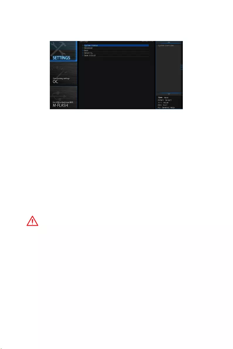
SETTINGS
System Status
fSystem Date
Sets the system date. Use tab key to switch between date elements.
The format is <day> <month> <date> <year>.
<day> Day of the week, from Sun to Sat, determined by BIOS. Read-only.
<month> The month from Jan. through Dec.
<date> The date from 1 to 31 can be keyed by numeric function keys.
<year> The year can be adjusted by users.
fSystem Time
Sets the system time. Use tab key to switch between time elements.
The time format is <hour> <minute> <second>.
fSATA PortX
Shows the information of connected SATA device.
Important
If the connected SATA device is not displayed, turn off computer and re-check SATA
cable and power cable connections of the device and motherboard.
fSystem Information
Shows detailed system information, including CPU type, BIOS version, and Memory
(read only).
fDMI Information
Shows system information, desktop Board Information and chassis Information. (Read
only).
Advanced
fPCI Subsystem Settings
Sets PCI, PCI express interface protocol and latency timer. Press Enter to enter the
sub-menu.

36 BIOS Setup
fPCI Latency Timer [32]
Sets latency timer of PCI interface device.
[Options: 32, 64, 96, 128, 160, 192, 224, 248 PCI Bus clocks]
fACPI Settings
Sets ACPI parameters of onboard power LED behaviors. Press Enter to enter the sub-
menu.
fACPI Standby State
Specifies the power saving modes for ACPI function.
fPower LED [Blinking]
Sets shining behaviors of the onboard Power LED.
[Dual Color] The power LED turns to another color to indicate the S3 state.
[Blinking] The power LED blinks to indicate the S3 state.
fIntegrated Peripherals
Sets integrated peripherals’ parameters, such as LAN, HDD, USB and audio. Press
Enter to enter the sub-menu.
fOnboard LAN Controller [Enabled]
Enables or disables the onboard LAN controller.
fLAN Option ROM [Disabled]
Enables or disables the legacy network Boot Option ROM for detailed settings. This
item will appear when Onboard LAN Controller is enabled.
[Enabled] Enables the onboard LAN Boot ROM.
[Disabled] Disables the onboard LAN Boot ROM.
fNetwork Stack [Disabled]
Sets UEFI network stack for optimizing IPv4 / IPv6 function.
[Enabled] Enables UEFI network stack.
[Disabled] Disables UEFI network stack.
fIpv4 PXE Support [Enabled]
When Enabled, the system UEFI network stack will support Ipv4 protocol. This item
will appear when Network Stack is enabled.
[Enabled] Enables the Ipv4 PXE boot support.
[Disabled] Disables the Ipv4 PXE boot support.
fIpv6 PXE Support [Enabled]
When Enabled, the system UEFI network stack will support Ipv6 protocol. This item
will appear when Network Stack is enabled.
[Enabled] Enables the Ipv6 PXE boot support.
[Disabled] Disables the Ipv6 PXE boot support.

37
BIOS Setup
fSATA Mode [AHCI Mode]
Sets the operation mode of the onboard SATA controller.
[AHCI Mode] Specify the AHCI mode for SATA storage devices. AHCI (Advanced
Host Controller Interface) offers some advanced features to enhance
the speed and performance of SATA storage device, such as Native
Command Queuing (NCQ) and hot-plugging.
[RAID Mode] Enables RAID function for SATA storage devices.
fSATAx Hot Plug [Disabled]
Allows user to enable or disable the SATA hot plug support.
[Enabled] Enables hot plug support for the SATA ports.
[Disabled] Disables hot plug support for the SATA ports.
fHD Audio Controller [Enabled]
Enables or disables the onboard High Definition Audio controller.
fHPET [Enabled]
Enables or disables the HPET (High Precision Event Timers) support.
fUSB Configuration
Sets the onboard USB controller and device function. Press <Enter> to enter the sub-
menu.
fUSB Controller [Enabled]
Enables or disables all USB controller.
fXHCI Hand-off [Enabled]
Enables or disables XHCI hand-off support for the operating system without XHCI
hand-off feature. This item will appear when USB Controller is enabled.
fEHCI Hand-off [Enabled]
Enables or disables EHCI hand-off support for the operating system without EHCI
hand-off feature.
fLegacy USB Support [Enabled]
Sets Legacy USB function support.
[Auto] The system will automatically detect if any USB device is connected
and enable the legacy USB support.
[Enabled] Enable the USB support under legacy mode.
[Disabled] The USB devices will be unavailable under legacy mode.
fOnboard USB 3.0 Controller [Enabled]
Enables or disables the external USB 3.0 controller.
fSuper IO Configuration
Sets system Super I/O chip parameters including LPT and COM ports. Press Enter to
enter the sub-menu.
fSerial (COM) Port 0 Configuration
Sets detailed configuration of serial(COM) port x. Press <Enter> to enter the sub-
menu.

38 BIOS Setup
fSerial (COM) Port 0 [Enabled]
Enables or disables serial (COM) port x.
fSerial (COM) Port 0 Settings [Auto]
Sets serial port x (COM). If set to Auto, BIOS will optimize the IRQ automatically or
you can set it manually.
fPower Management Setup
Sets system Power Management of EuP2013 and AC Power Loss behaviors. Press
Enter to enter the sub-menu.
fEuP 2013 [Disabled]
Enables or disables the system power consumption according to EuP2013
regulation. When enabled, the system will not support RTC wake up event
functions.
[Enabled] Optimize the system power consumption according to EuP 2013
regulation. It will not support S4 & S5 wake up by USB and PCIe
devices.
[Disabled] Disables this function.
fRestore after AC Power Loss [Power Off]
Sets the system behaviors while encountering the AC power loss.
[Power Off] Leaves the system in power off state after restoring AC power.
[Power On] Boot up the system after restoring AC power.
[Last State] Restores the system to the previous state (power on/ power off)
before AC power loss.
fWindows 8 Configuration
Sets Windows 8/ 8.1 detailed configuration and behaviors. Press <Enter> to enter
the sub-menu.
fWindows 8 Feature [Disabled]
Enables the supports for Windows 8/ 8.1 or disables for other operating systems.
Before enabling this item, make sure all installed devices & utilities (hardware &
software) should meet the Windows 8/ 8.1 requirements.
[Enabled] The system will switch to UEFI mode to meet the Windows 8
requirement.
[Disabled] Disables this function.
fMSI Fast Boot [Disabled]
MSI Fast Boot is the fastest way to boot the system. It will disable more devices to
speed up system boot time which is faster than the boot time of Fast Boot.
[Enabled] Enables the MSI Fast Boot function to speed up booting time. And
the following Fast Boot field will be disabled and fixed.
[Disabled] Disables MSI Fast Boot.
Important
When MSI Fast Boot is enabled, you can use MSI FAST BOOT application to enter BIOS
setup if needed. Please refer Entering BIOS Setup section for details.

39
BIOS Setup
fFast Boot [Disabled]
Enables or disables the fast boot feature for Windows 8/ 8.1. This item will only be
available when MSI Fast Boot is disabled.
[Enabled] Enables the Fast Boot configuration to accelerate system boot time.
[Disabled] Disables the Fast Boot configuration.
fWake Up Event Setup
Sets system wake up behaviors for different sleep modes. Press <Enter> to enter the
sub-menu.
fWake Up Event By [BIOS]
Selects the wake up event by BIOS or operating system.
[BIOS] Activates the following items, set wake up events of these items.
[OS] The wake up events will be defined by OS.
fResume By RTC Alarm [Disabled]
Enables or disables the system wake up by RTC Alarm.
[Enabled] Enables the system to boot up on a scheduled time/ date.
[Disabled] Disables this function.
fDate (of month) Alarm/ Time (hh:mm:ss) Alarm
Sets RTC alarm date/ Time. If Resume By RTC Alarm is set to [Enabled], the system
will automatically resume (boot up) on a specified date/hour/minute/second in
these fields (using the <+> and <-> to select the date & time settings).
fResume By PCI-E Device [Disabled]
Enables or disables the system wake up by PCI-E devices.
[Enabled] Enables the system to be awakened from the power saving modes
when activity or input signal of PCI-E device is detected. Note:
enables this Item to support Resume by USB Device with third party
USB port if any.
[Disabled] Disables this function.
fResume From S3 by USB Device [Disabled]
Enables or disables the system wake up by USB devices.
[Enabled] Enables the system to be awakened from S3 (suspend to RAM) sleep
state when activity of USB device is detected.
[Disabled] Disables this function.
fResume From S3/S4/S5 by PS/2 Mouse [Disabled]
Enables or disables the system wake up by PS/2 mouse.
[Enabled] Enables the system to be awakened from S3/ S4/ S5 state when
activity of PS/2 mouse is detected.
[Disabled] Disables this function.

40 BIOS Setup
fResume From S3/S4/S5 by PS/2 Keyboard [Disabled]
Enables or disables the system wake up by PS/2 keyboard.
[Any Key] Enables the system to be awakened from S3/ S4/ S5 state when
activity of any key on PS/2 keyboard is detected.
[Hot Key] Enables the system to be awakened from S3/ S4/ S5 state when
activity of hot key on PS/2 keyboard is detected.
[Disabled] Disables this function.
Boot
Sets the sequence of system boot devices.
fFull Screen Logo Display [Enabled]
Enables or disables to show the full screen logo while system POST.
[Enabled] Shows the logo in full screen.
[Disabled] Shows the POST messages.
fBoot Mode Select [LEGACY+UEFI]
Sets the system boot mode from legacy or UEFI architecture depending on OS
installation requirement. This item will become un-selectable and will be configured
automatically by BIOS when Windows 8 Feature is enabled.
[UEFI] Enables UEFI BIOS boot mode support only.
[LEGACY+UEFI] Enables both Legacy BIOS boot mode and UEFI BIOS boot
mode.
fFIXED BOOT ORDER Priorities
Sets device priority for system boot.
fBoot Option Priorities
These items are used to prioritize the installed boot devices.
Security
fAdministrator Password
Sets administrator password for system security. User has full rights to change the
BIOS items with administrator password. After setting the administrator password, the
state of this item will show “Installed”.
fUser Password
Sets User Password for system security. User has limited rights to change the BIOS
items with user password. This item will be available when administrator password is
set. After setting the user password, the state of this item will show Installed.

41
BIOS Setup
Important
When selecting the Administrator / User Password items, a password box will appear
on the screen. Type the password then press <Enter>. The password typed now will
replace any previous set password from CMOS memory. You will be prompted to
confirm the password. You may also press <Esc> to abort the selection.
To clear a set password, press <Enter> when you are prompted to enter a new
password. A message will confirm the password is being disabled. Once the password
is disabled, you can enter the setup and OS without authorization.
fU-Key [Disabled]
Enables or disables U-Key as user’s password to access the system.
fMake U-Key at
Makes a key at the USB flash drive to prevent other people from accessing the system.
Only the user who has the key with the flash drive can access the system.
fChassis Intrusion Configuration
Press Enter to enter the sub-menu.
fChassis Intrusion [Disabled]
Enables or disables recording messages when the chassis is opened. This function
is ready for the chassis equips a chassis intrusion switch.
[Enabled] Once the chassis is opened, the system will record and issue a
warning message.
[Reset] Clear the warning message. After clearing the message, please
return to Enabled or Disabled.
[Disabled] Disables this funcion.
Save & Exit
fDiscard Changes and Exit
Exit BIOS setup without saving any change.
fSave Changes and Reboot
Save all changes and reboot the system.
fSave Changes
Save current changes.
fDiscard Changes
Discard all changes and restore to the previous values.
fRestore Defaults
Restore or load all default values.
fBoot Override
The installed bootable devices will appear on this menu, you can select one of them to
be the boot device.
42 BIOS Setup
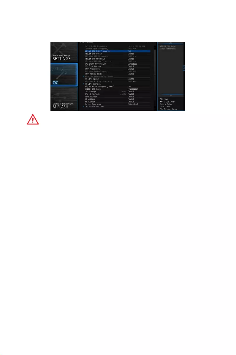
OC
Important
y
Overclocking your PC manually is only recommended for advanced users.
y
Overclocking is not guaranteed, and if done improperly, it could void your warranty
or severely damage your hardware.
y
If you are unfamiliar with overclocking, we advise you to use OC Genie function for
easy overclocking.
fCurrent CPU/ DRAM Frequency
These items show the current frequencies of installed CPU and Memory. Read-only.
fAdjust CPU FSB Frequency
Allows you to set the CPU FSB frequency (in MHz). You may overclock the CPU by
adjusting this value. Please note that overclocking behavior and stability is not
guaranteed.
fAdjust CPU Ratio [Auto]
Sets the CPU ratio that is used to determine CPU clock speed. This item can only be
changed if the processor supports this function.
fAdjusted CPU Frequency
Shows the adjusted CPU frequency. Read-only.
fAdjust CPU-NB Ratio [Auto]
Sets the CPU-NB ratio that is used to determine CPU-NB clock speed.
fAdjusted CPU-NB Frequency
Shows the adjusted CPU frequency. Read-only.
fCPU Smart Protection [Enabled]
CPU Smart Protection is a mechanism of CPU overheating protection. It will
automatically reduce the clock when the CPU temperature gets too high.

43
BIOS Setup
fCPU Core Control [Auto]
This item allows you to select the number of active processor cores. When set to Auto,
the CPU will operate under the default number of cores.
fDRAM Frequency [Auto]
Sets the DRAM frequency. Please note the overclocking behavior is not guaranteed.
fAdjusted DRAM Frequency
Shows the adjusted DRAM frequency. Read-only.
fDRAM Timing Mode [Auto]
Selects the memory timing mode.
[Auto] DRAM timings will be determined based on SPD (Serial Presence
Detect) of installed memory modules.
[Link] Allows user to configure the DRAM timing manually for all
memorychannel.
[UnLink] Allows user to configure the DRAM timing manually for respective
memory channel.
fAdvanced DRAM Configuration
Press Enter to enter the sub-menu. This sub-menu will be activated after setting Link
or Unlink in DRAM Timing Mode. User can set the memory timing for each memory
channel. The system may become unstable or unbootable after changing memory
timing. If it occurs, please clear the CMOS data and restore the default settings. (Refer
to the Clear CMOS jumper section to clear the CMOS data, and enter the BIOS to load
the default settings.)
fHT Link Speed [Auto]
This item allows you to set the Hyper-Transport Link speed. When Auto, the system
will detect the HT link speed automatically.
fAdjusted HT Link Frequency
It shows the adjusted HT Link frequency. Read-only.
fHT Link Control
Press Enter to enter the sub-menu.
fHT Incoming/ Outgoing Link Width
These items allow you to set the Hyper-Transport Link width. When Auto, the
system will detect the HT link width automatically.
fAdjust PCI-E Frequency (MHz)
Sets the PCI Express frequency.
fUnlock CPU Core [Disabled]
This item is used to unlock the CPU core. Please refer to the procedures below for
CPU core unlocked in BIOS setup.

44 BIOS Setup
Success
Enter OC and set Unlock CPU Core to Enabled.
Save changes and exit the BIOS setup.
System restart.
You will see the “X4” (quad core) or “X2” (dual core for
Sempron series only) during POST.
Fail
Set Adjust CPU-NB Ratio and HT
Link Speed to [x8].
AMD Phenom(tm) II X4 Processor
Clear CMOS data.
The CPU does not support CPU core
unlocking, please leave the default
settings for system.
AMD Sempron(tm) II X2 Processor
Important
y
This CPU core unlocked behavior depends on the CPU ability/ characteristic, and it
is not guaranteed.
y
Depend on CPU’s characteristic, once you get instable scenario, please restore the
default settings for system.
y
You can also check the core numbers in performance tab of Windows task manager.
fCPU/ CPU-NB/ DRAM/ SB/ NB Voltages control [Auto]
These options allows you to set the voltages related to CPU/ memory/ SB/ NB. If set to
Auto, BIOS will set these voltages automatically or you can set it manually.
fSpread Spectrum [Disabled]
This function reduces the EMI (Electromagnetic Interference) generated by
modulating clock generator pulses.
[Enabled] Enables the spread spectrum function to reduce the EMI
(Electromagnetic Interference) problem.
[Disabled] Enhances the overclocking ability of CPU Base clock.
Important
y
If you do not have any EMI problem, leave the setting at [Disabled] for optimal
system stability and performance. But if you are plagued by EMI, select the value of
Spread Spectrum for EMI reduction.
y
The greater the Spread Spectrum value is, the greater the EMI is reduced, and the
system will become less stable. For the most suitable Spread Spectrum value,
please consult your local EMI regulation.
y
Remember to disable Spread Spectrum if you are overclocking because even a
slight jitter can introduce a temporary boost in clock speed which may just cause
your overclocked processor to lock up.

45
BIOS Setup
fCPU Specifications
Press Enter to enter the sub-menu. This sub-menu displays the information of
installed CPU. You can also access this information menu at any time by pressing F4.
Read only.
fCPU Technology Support
Press Enter to enter the sub-menu. The sub-menu shows the key features of
installed CPU. Read only.
fMEMORY-Z
Press Enter to enter the sub-menu. This sub-menu displays all the settings and
timings of installed memory. You can also access this information menu at any time by
pressing F5.
fDIMMx Memory SPD
Press <Enter> to enter the sub-menu. The sub-menu displays the information of
installed memory. Read only.
fCPU Features
Press Enter to enter the sub-menu.
fAMD Cool’n’Quiet [Auto]
Enabled or disabled AMD Cool’n’Quiet function.
[Auto] Depends on AMD Design.
[Enable] Enables AMD Cool’n’Quiet function. The Cool’n’Quiet technology
can effectively and dynamically lower CPU speed and power
consumption.
[Disabled] Disables this function.
Important
When adjusting CPU Ratio, the Cool’n’Quiet function will be disabled automatically.
For CPU which supports the Turbo Core Tech., please set AMD Turbo Core Technology
and AMD Cool’n’Quiet as Disabled to retain the default CPU core speed.
fC1E Support
Enables this item to reduce the CPU power consumption while idle. Not all
processors support Enhanced Halt state (C1E).
fSVM Mode [Enabled]
Enables or disables CPU Virtualization.
[Enabled] Enables CPU Virtualization and allows a platform to run multiple
operating systems in independent partitions. The system can
function as multiple systems virtually.
[Disabled] Disables this function.
fIOMMU Mode
Enables/disables the IOMMU (I/O Memory Management Unit) for I/O Virtualization.
46 BIOS Setup
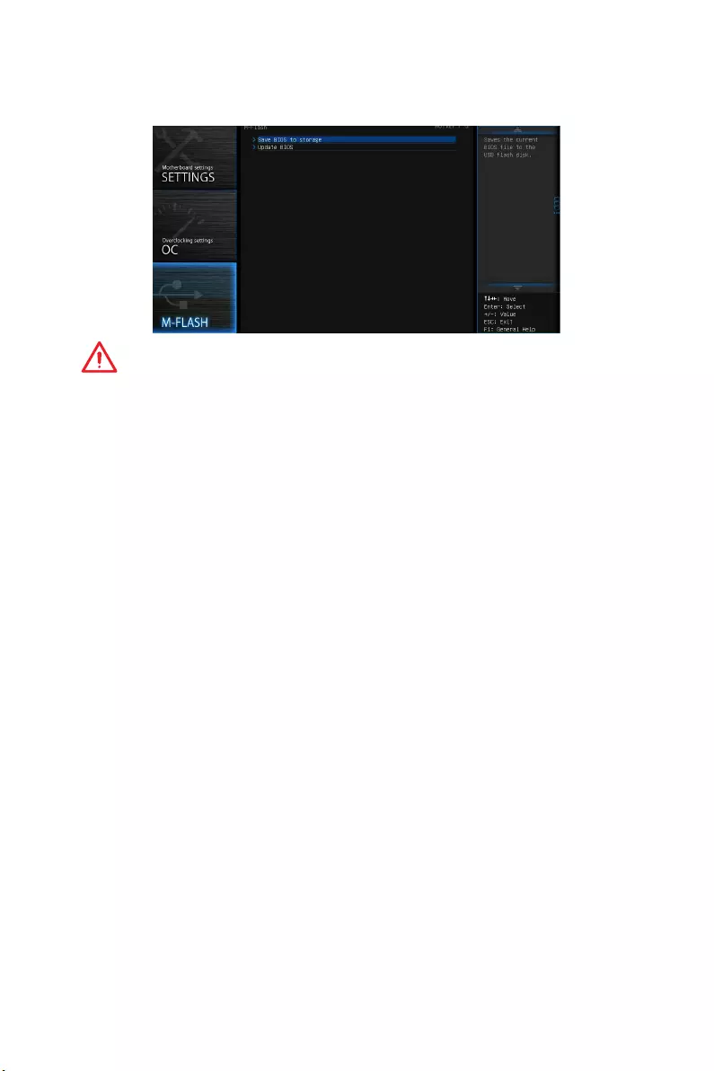
M-FLASH
Important
M-Flash function allows you to update BIOS from USB flash disk (FAT32/ NTFS format
only).
fSave BIOS to storage
Saves the current BIOS file to the USB flash disk. The USB flash disk drive should be in
FAT32 format.
fUpdate BIOS
Selects a BIOS file in the USB flash disk (NTFS/ FAT32 format) to update the BIOS.
fSelect one file to update BIOS
Selects a BIOS file in the USB flash disk (NTFS/ FAT32 format)
47
BIOS Setup
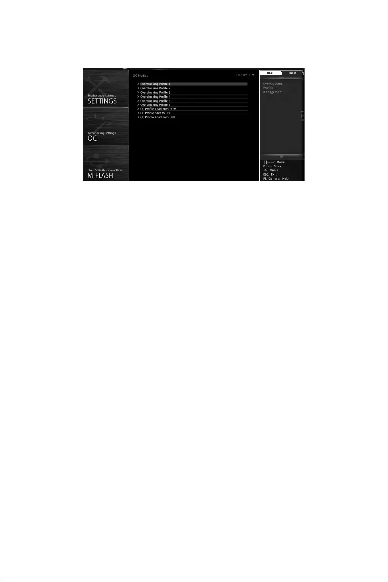
OC PROFILE
fOverclocking Profile 1/ 2/ 3/ 4/ 5/ 6
Overclocking Profile 1/ 2/ 3/ 4/ 5/ 6 management. Press Enter to enter the sub-menu.
fSet Name for Overclocking Profile 1/ 2/ 3/ 4/ 5/ 6
Name the current overclocking profile.
fSave Overclocking Profile 1/ 2/ 3/ 4/ 5/ 6
Save the current overclocking profile.
fLoad Overclocking Profile 1/ 2/ 3/ 4/ 5/ 6
Load the current overclocking profile.
fClear Overclocking Profile 1/ 2/ 3/ 4/ 5/ 6
Clear the current overclocking profile.
fOC Profile Save to USB
Save OC profile to the USB flash drive. The USB flash drive should be FAT/ FAT32
format only.
fOC Profile Load from USB
Load OC profile from the USB flash drive. The USB flash drive should be FAT/ FAT32
format only.
48 BIOS Setup
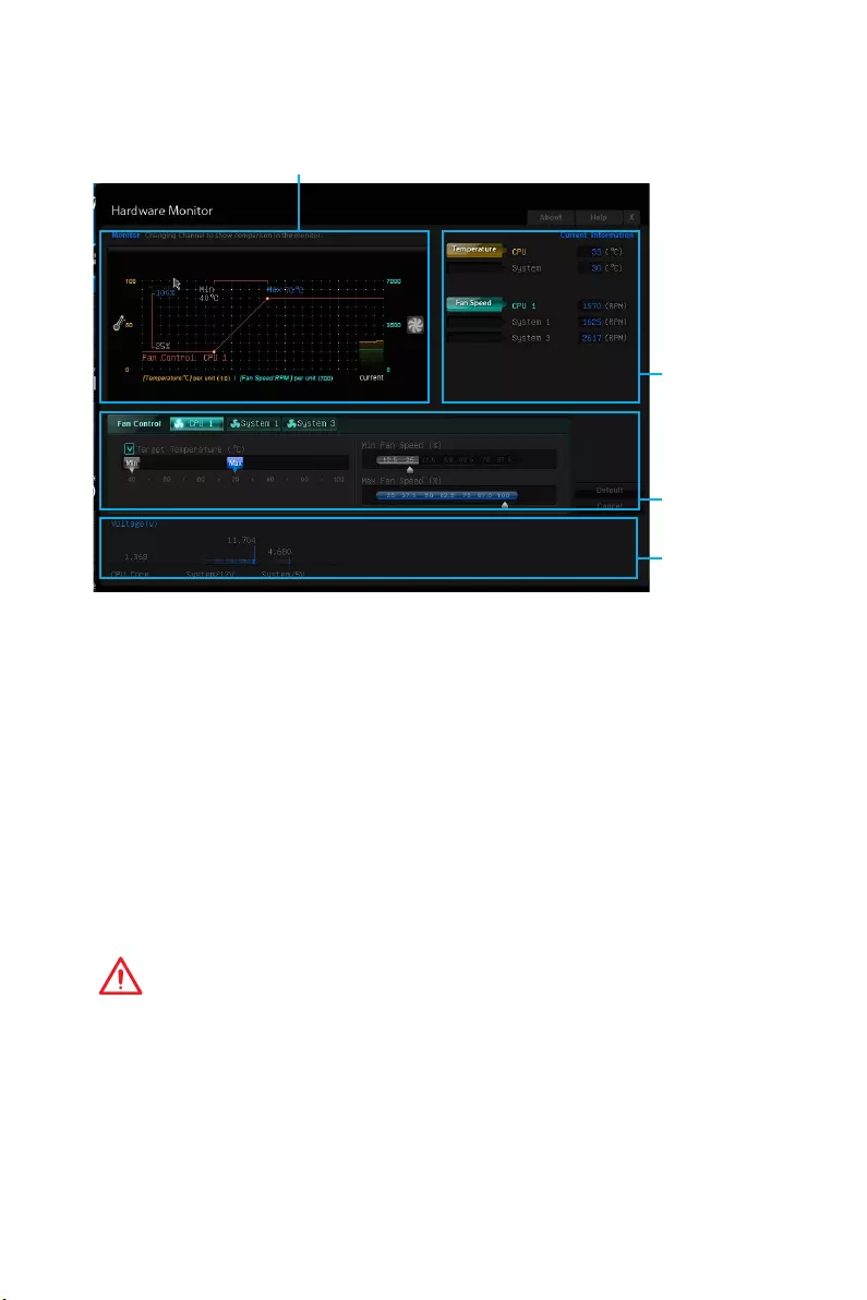
HARDWARE MONITOR
Temperature & Speed graphic display
Temperature
& Speed
information
Voltage
display
Fan
control
field
fTemperature & Speed information
Shows the current CPU temperature, system temperature and fans’ speeds.
fTemperature & Speed graphic display
The red graph shows the minimum and maximum temperatures that be set on the Fan
control field. The yellow graph shows current CPU/ system temperature. The green
shows current CPU/ System fan speed.
fFan control field
Smart Fan Control automatically controls fan speed depending on the current CPU
temperature and to keep it with a specific operating speed. When the current CPU
temperature is over the maximum temperature, the CPU/ system fan will run at
the maximum speed. When the current CPU temperature is under the minimum
temperature, the CPU/ system fan will run at the minimum speed. In this field, you can
set the CPU and system fans’ speeds and target temperatures.
Important
The changing will achieve after you save the changes and reboot the system.
fVoltage display
Shows the current voltages of CPU, system and memory.

49
Software Description
Software Description
Installing Drivers
1. Start up your computer in Windows® 7/ 8.1/ 10.
2. Insert MSI® Driver Disc into your optical drive.
3. The installer will automatically appear and it will find and list all necessary
drivers.
4. Click Install button.
5. The software installation will then be in progress, after it has finished it will
prompt you to restart.
6. Click OK button to finish.
7. Restart your computer.
Installing Utilities
Before you install utilities, you must complete drivers installation.
1. Insert MSI® Driver Disc into your optical drive.
2. The installer will automatically appear.
3. Click Utilities tab.
4. Select the utilities you want to install.
5. Click Install button.
6. The utilities installation will then be in progress, after it has finished it will prompt
you to restart.
7. Click OK button to finish.
8. Restart your computer.
50 Software Description
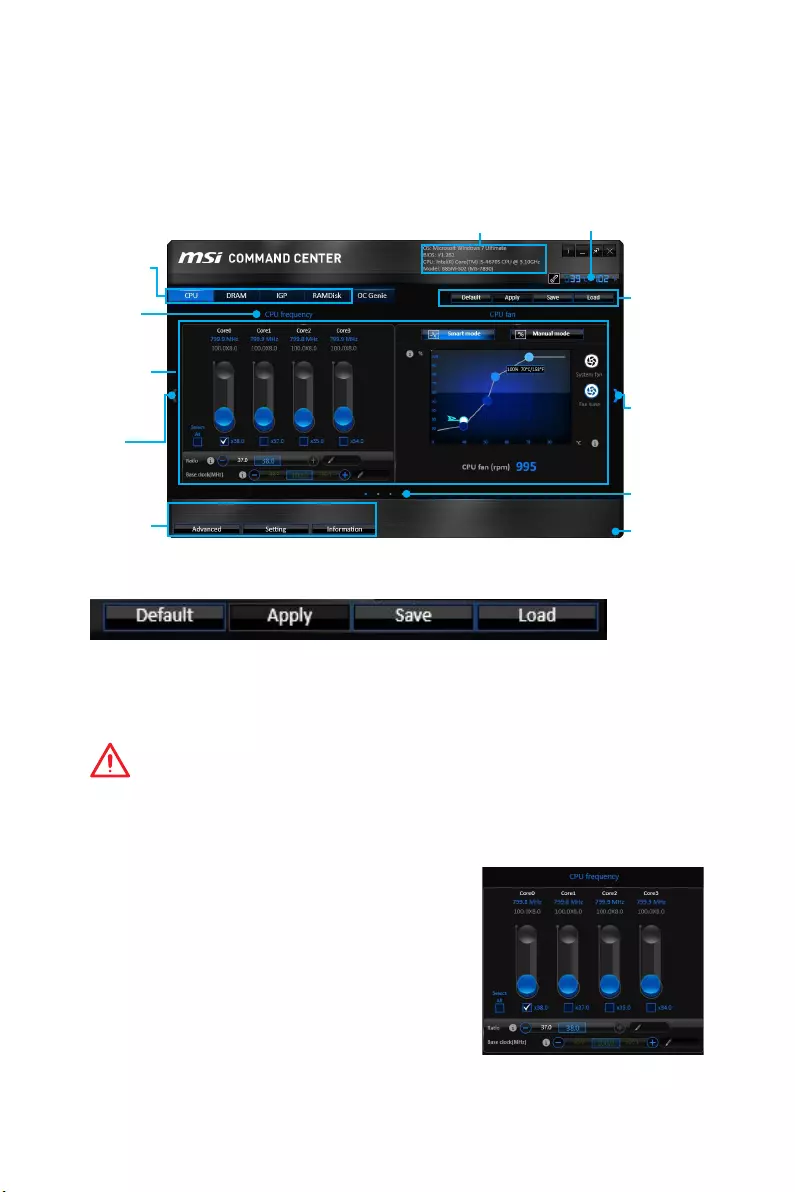
COMMAND CENTER
COMMAND CENTER is an user-friendly software and exclusively developed by MSI,
helping users to adjust system settings and monitor status under OS. With the help
of COMMAND CENTER, making it possible to achieve easier and efficient monitoring
process and adjustments than that under BIOS. In addition, the COMMAND CENTER
can be a server for mobile remote control application.
Feature Menu
CPU TemperatureSystem Information
Feature Title
Feature
Control Panel
Previous
Feature
Next Feature
Profile
Buttons
Option Buttons
Page Indicator
Resize Corner
Profile Buttons
yDefault — load the default values for the current feature.
yApply — apply your changes.
ySave — store values in the file with individual file extension.
yLoad — load the values from the file.
Important
Every time you shut down the system, the configured setting will be restored to the
factory default. If you want to use the saved settings, you have to load it every time by
clicking the Load and Apply buttons.
CPU Frequency
CPU Frequency control panel allows you to change
CPU Ratio and Base clock. You can see the current
frequency of each CPU core on the top of the panel.
51
Software Description
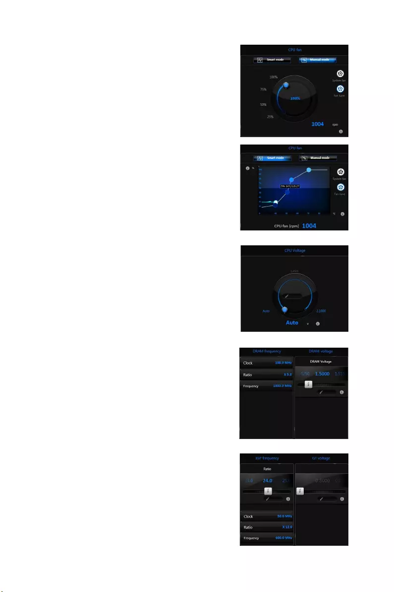
CPU Fan
CPU Fan control panel provides Smart mode and
Manual Mode. You can switch the control mode by
clicking the Smart Mode and Manual Mode buttons
on the top of the CPU Fan control panel.
yManual Mode — allows you to manually control the
CPU fan speed by percentage.
ySmart Mode — a linear fan speed control feature.
The control panel contains 4 dots allows you to
drag and adjust the Smart Speed slopes. The fan
speed will be changed along these lines with CPU
temperature. The white dot will create strip chart
in real time.
ySystem Fan Button — to open the system fan
control panel in new window.
yFan Tune Button — to automatically optimize the
smart fan setting.
Manual Mode
Smart Mode
IGP Frequency & GT Voltage
yIGP Frequency — Allows you to adjust the IGP ratio,
and shows the IGP clock, ratio and frequency.
yGT Voltage — Allows you to adjust the GT voltage.
The risky values are displayed in red.
DRAM Frequency & DRAM Voltage
yDRAM Frequency — Shows the DRAM clock, ratio
and frequency.
yDRAM Voltage — Allows you to adjust the DRAM
voltage. The risky values are displayed in red.
CPU Voltage
CPU Voltage control panel allows you to control the
CPU voltage.
52 Software Description
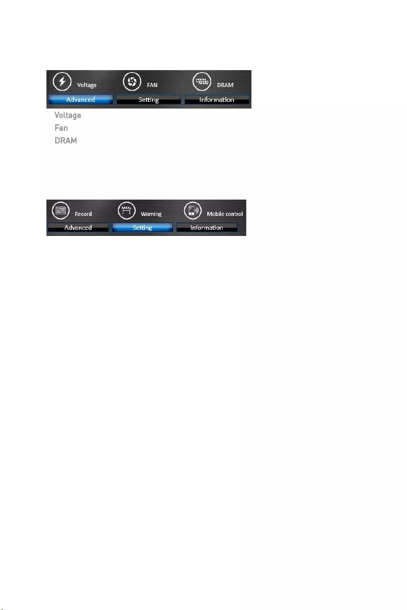
Option Buttons — Advanced
When click the Advanced button, The Voltage, Fan and DRAM icons will appear.
yVoltage — allows you to adjust advanced voltage values of CPU and chipset.
yFan — allows you to control the system fans speed.
yDRAM — shows the current Advanced DRAM parameters, and allows you to change
the settings by selecting values from the drop-down menu on the right hand side.
Option Buttons — Setting
When click the Setting button, The Record, Warning and Mobile Control icons will
appear.
yRecord — allows you to monitor the status of voltage, fan speed and temperature in
real time.
To filter record charts, select the check box next to the items.
When click the Play button, the chart pane will start to show the recording chart.
If you want to check the value of a specific spot on chart, please move the orange
vertical line to the spot.
History Record stores the data and names with date and time.
To make a history record: Select items and click the Record button. When finished,
click the Record button again. The data will be stored in the drop-down menu.
To load a record, click the drop-down menu and select one from the list.
To delete a record, select the record that you want to delete, and click the Trash
Can icon.
53
Software Description
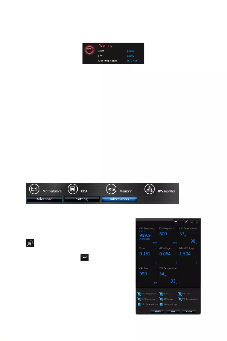
yWarning — contains fields of voltage, fan speed and temperature for you to set the
threshold values. When system detects the status over your settings, a warning
message will pop-up.
yMobile Control — is only available for the motherboard with the built-in WiFi module.
It allows you to enable/disable the COMMAND CENTER Remote Server. Please refer
to the instruction on the Mobile Control control panel.
yTo start remote control: (optional)
1. Download and install MSI® COMMAND CENTER APP to your mobile device.
2. Enable COMMAND CENTER Remote Server on the Mobile Control panel.
3. Enable SoftAP Management.
4. Enter SSID and Password, and then click the Apply button.
5. Activate Wi-Fi® on your mobile device and connect to SoftAP with the SSID.
6. Run MSI® COMMAND CENTER APP on your mobile device.
7. Find the IP address on the SoftAP Management Setting area, and enter the IP
address on your MSI® COMMAND CENTER APP to link your system.
8. Press Refresh on the MSI® COMMAND CENTER APP to verify that monitoring and
OC functions are working properly.
Option Buttons — Information
When click the Information button, The Motherboard, CPU, Memory and HW monitor
icons will appear.
You can click the icons to open the related information.
Gadget Mode
COMMAND CENTER provides a gadget mode to
monitor the system status. You can switch between
gadget mode and full mode by clicking the arrow icon
on the top left.
yTo arrange gadgets:
1. Click the Spanner icon on the Gadget mode,
a configuration panel will slide out.
2. Select the check box next to the items.
3. Click the Close button.
54 Software Description
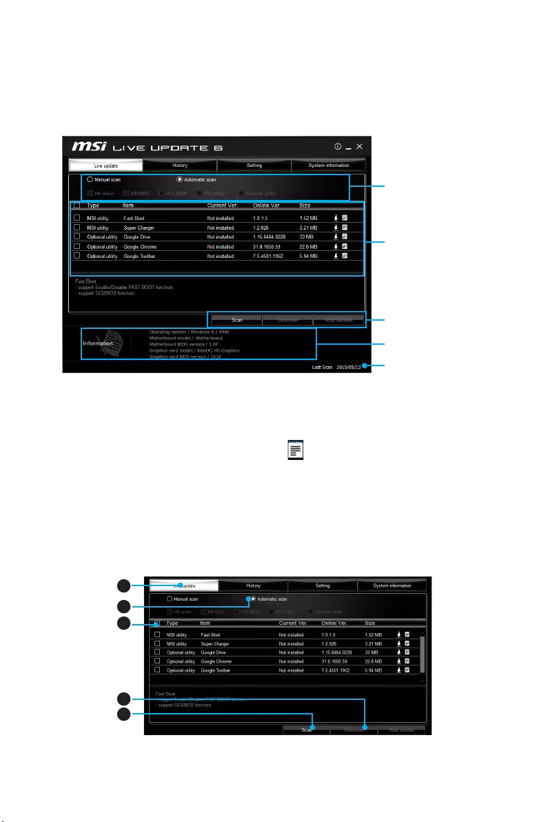
LIVE UPDATE 6
LIVE UPDATE 6 is an application for the MSI® system to scan and download the latest
drivers, BIOS and utilities. With LIVE UPDATE 6, you don’t need to search the drivers
on websites, and don’t need to know the models of motherboard and graphics cards.
LIVE UPDATE 6 will download the appropriate drivers automatically.
Download Options
Download List
Scan / Download / Total
Installer button
System Information
Last Scanned Date
There are Live Update, History, Setting and System Information tabs at the top. You
can click the tab to switch the control panel.
yLive Update — When you launch LIVE UPDATE 6, you will see the Live update tab at
first. This tab allows you to select files to download. You can also read the relevant
information by clicking the information icon on the right of the item listed.
yHistory — shows the downloading history.
ySetting — allows you to specify the frequency that LIVE UPDATE 6 remind you to
update.
ySystem Information — displays the information of the system.
Updating The System
This section describes how to update your system with LIVE UPDATE 6. Please follow
the steps below:
1
2
4
5
3
1. Select the Live Update tab.
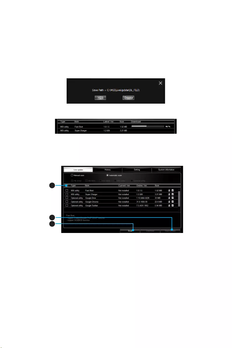
55
Software Description
2. Choose Automatic scan, system will automatically scan all the items and search
for the latest update files. Or you can choose Manual scan and select the items you
wish to scan.
3. Click the Scan button at the bottom. It may take several moments to complete the
process.
4. When the download list appears, please select the items you intend to update.
5. Click Download button at the bottom.
6. When Save Path prompt, you can specify a download directory.
7. When downloading you will see the screen below. It may take several moments to
complete the process.
8. To install the applications, simply unpack the packages and install.
Total Installer
Total Installer is a convenient feature to simplify frequent installing procedure. To use
Total Installer:
1
2
3
1. Scan updates in Live Update tab.
2. Check the Select All check-box you intend to update.
3. Click the Total Installer button. LIVE UPDATE 6 will automatically install them.
4. When prompted, click OK to complete the Total Installer procedure.
5. Reboot your system.
56 Software Description
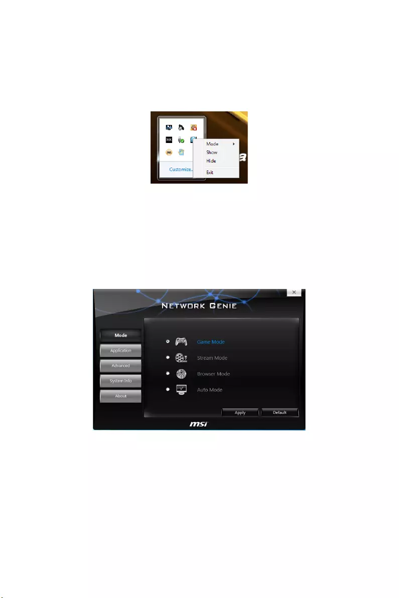
NETWORK GENIE
NETWORK GENIE is an utility to optimize the traffic for bandwidth control. NETWORK
GENIE is designed for the Realtek LAN chip with Windows 7, Windows 8.1 and
Windows 10 platforms.
Once installed, the Network Genie icon shows on system tray (the right bottom corner
of the screen). Mouse right click at the icon, will display the following screen.
When you hover the mouse cursor over the Mode option, a sub-menu will appear for
you to select Game, Stream, Browser and Auto mode.
yShow — shows the NETWORK GENIE control panel.
yHide — hides the NETWORK GENIE control panel.
yExit — exits NETWORK GENIE.
In case no icon is shown on the system tray, it is possible to activate NETWORK GENIE
manually by clicking Start > Programs > MSI > NETWORK GENIE > NETWORK GENIE.
NETWORK GENIE Control Panel
yMode — allows you to quickly change bandwidth priorities for different applications.
yApplications — lists all network related applications.
yAdvanced — provides detailed settings for NETWORK GENIE.
ySystem Info — shows system information.
yAbout — shows information of NETWORK GENIE.
57
Software Description
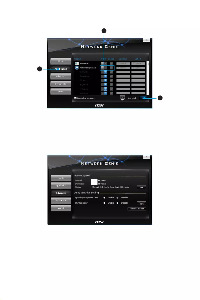
Configuring Application’s Network Priority
2
1
3
1. Go to Application tab.
2. Click L to assign the low network priority to the application, and H to hight. You
can also click the Lock icon to block an application network connection.
3. Click the Save button to store your settings.
Configuring Network Speed
There are two parts in the Advanced tab, one is Internet Speed, and another is Delay/
Sensitivity Settings.
yInternet Speed — allows you to set the maximum available bandwidth to the upload/
download speed manually or just leave blank for no limit.
yDelay/Sensitivity Settings — allows you to enable Speed up Response Time and No
TCP Delay to reduce the latency of the high priority applications.
58 RAID Configuration
RAID Configuration
Below are the different types of a RAID.
RAID 0 breaks the data into blocks which are written to separate hard drives.
Spreading the hard drive I/O load across independent channels greatly
improves I/O performance.
RAID 1 provides data redundancy by mirroring data between the hard drives and
provides enhanced read performance.
RAID 5 provides data striping at the byte level and also stripe error correction
information. This results in excellent performance and good fault tolerance.
RAID 10 uses four hard drives to create a combination of RAID 0 and 1 by forming a
RAID 0 array from two RAID 1 arrays.
RAID level comparison
RAID 0 RAID 1 RAID 5 RAID 10
Minimum # drives 2 2 3 4
Data protection None Excellent Excellent Excellent
Read performance Excellent OK Good OK
Write performance Excellent Good OK Good
Capacity utilization 100% 50% 67%~(1-1/n) 50%
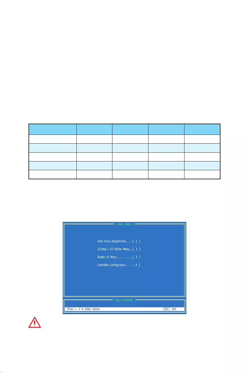
Using AMD® RAID Option ROM utility
First, you need to set the SATA mode to RAID in BIOS to create, delete and reset RAID
volumes. To enter the RAID Option ROM, reboot and press Ctrl + F keys to enter the
RAID Option ROM utility during the POST, the following window will appear.
Important
The following procedure is only available with a newly-built system or if you are
reinstalling your OS. It should not be used to migrate an existing system to RAID.

59
RAID Configuration
Creating RAID Volume
1. Press 2 on the main menu and then press Ctrl + C keys. Then following screen
appears.
2. Use the space key to choose a RAID mode (RAID 0/ 1/ 10/ 5) and use the arrow key
to move to the Drives Assignments window.
Stripe Block Size, the default 64KB is best for RAID 0 or 10.
Gigabyte Boundary, allows use of slightly smaller replacement drives.
3. On the Drives Assignments window, use the arrow keys to choose the hard drives
which you want to make part of RAID volume, and use the space key to change the
Assignment to Y. Then press Ctrl + Y keys to save the configuration.
4. A message will show, press Ctrl + Y to manually input a name as a RAID volume
name or press any key to save default name.
5. Another message will show, press Ctrl + Y keys if you are sure to erase the MBR
data of the disk. Or press any key to ignore this option.
6. The message will show up on the bottom, press any key to use maximum capacity
or press Ctrl + Y keys to modify array capacity manually.
60 RAID Configuration
Important
Since you want to create two volumes, this default size (maximum) needs to be
reduced. Type in a new size for the first volume. As an example: if you want the first
volume to span the first half of the two disks, re-type the size to be half of what is
shown by default. The second volume, when created, will automatically span the
remainder of two hard drives.
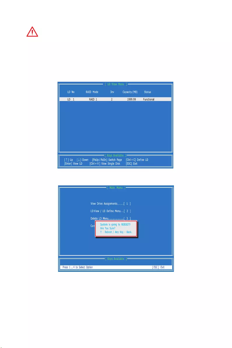
7. The RAID creation is done, the screen shows the information as below. Press ESC
key to return to the main screen.
8. Finally, press ESC key to exit the utility, a message System is going to REBOOT!
Are You Sure? will display, press Y to exit it and the system will reboot.
61
RAID Configuration
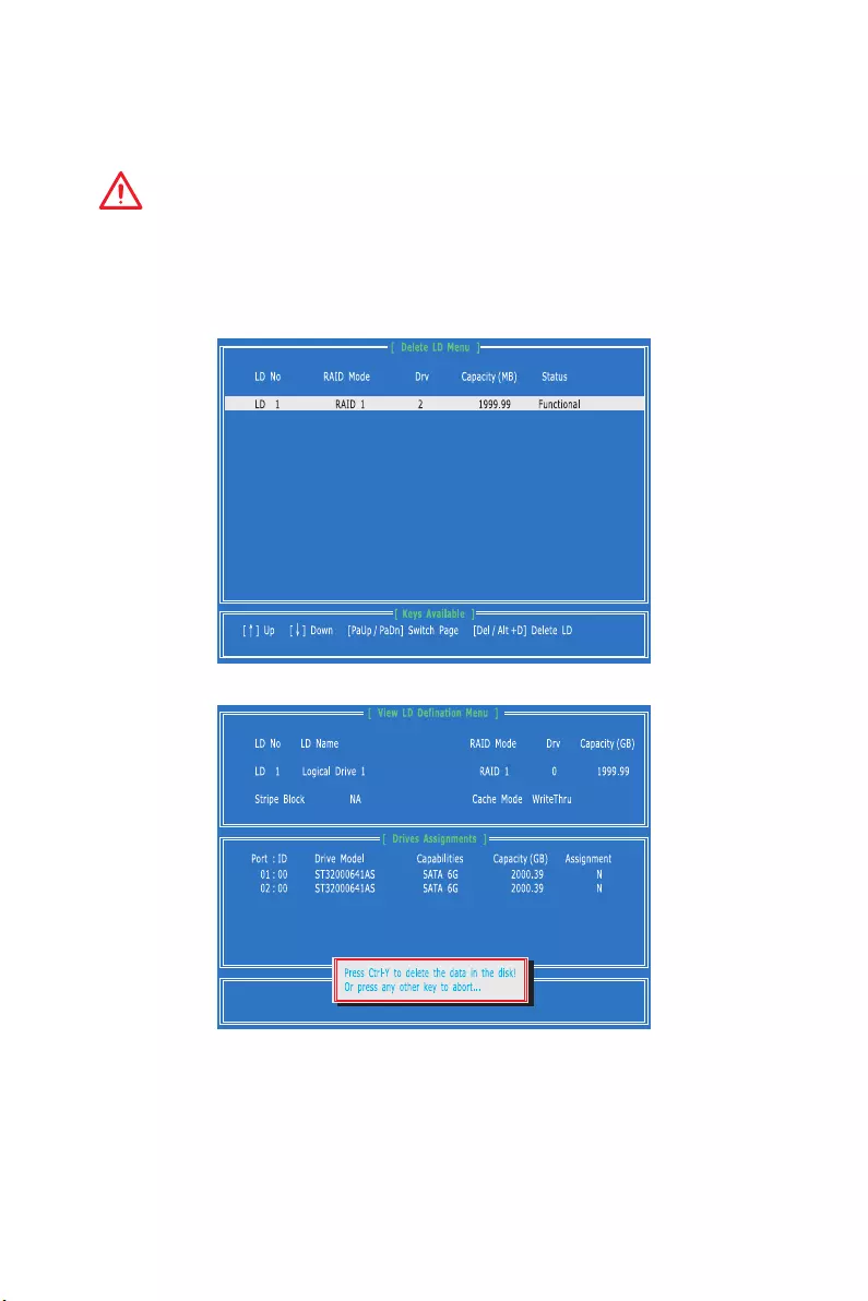
Delete RAID Volume
Here you can delete the RAID volume, but please be noted that all data on RAID drives
will be lost.
Important
If your system currently boots to RAID and you delete the RAID volume in the RAID
Option ROM, your system will become unbootable.
1. Press 3 on the main menu to enter the Delete LD Menu.
2. Choose a LD No you want to delete and press Del key or Alt + D keys to delete the
RAID volume.
3. A message will display, press Ctrl + Y to delete the RAID volume.

62 Troubleshooting
Troubleshooting
Before sending the motherboard for RMA
repair, try to go over troubleshooting
guide first to see if your got similar
symptoms as mentioned below.
The power is not on.
yConnect the AC power cord to an
electrical outlet securely.
yCheck if all ATX power connectors like
JPWR1~2 is connected from the power
supply to the motherboard?
ySome power supply units have a power
button on the rear side, make sure the
button is turned on.
yCheck if the power switch cable is
connected to JFP1 pin header properly.
yVerify the Clear CMOS jumper JBAT1 is
set to Keep DATA.
yTest with another known working
power supply of equal or greater
wattage.
The power is on, but no signal to
monitor
yConnect the monitor power cord to a
electrical outlet securely.
yMake sure the monitor is turned on.
ySelect different inputs on the monitor.
yIf 3 long beeps are heard, remove all
memory modules and try to install only
one memory module into the DIMM1
slot first and then restart the computer.
yIf 1 long 2 short beeps are heard,
remove and reinstall the graphics card
and then restart the computer.
yTest with another known working
graphics card.
The computer does not boot after
updating the BIOS
yClear the CMOS.
yUse the secondary BIOS to bootup the
system (Only for motherboard with
Dual BIOS)
Lost BIOS password
yClear the CMOS, but that will cause
you to lose all customized settings in
the BIOS.
There is no audio
yAdjust the volume.
yConnect the speakers/headphones to
audio ports on the motherboard rear
IO panel.
yTest with another known working
speaker or headphone.
There is no network
yMake sure the network chipset driver
has been installed.
yVerify if the network cable is properly
connected and make sure the LAN port
LEDs are properly illuminated.
yVerify your TCP/IP settings.
yRestart or reset your router.
yTest with another known working LAN
cable.
The USB device is not working
yMake sure your USB driver has been
installed.
yVerify if USB device is listed in
Windows® Device Manager.
yConnect the USB device to other USB
port on the motherboard rear IO panel.

63
Regulatory Notices
FCC Compliance Statement
Note: This equipment has been tested and found to
comply with the limits for a Class B digital device,
pursuant to part 15 of the FCC Rules. These limits
are designed to provide reasonable protection against
harmful interference in a residential installation. This
equipment generates, uses and can radiate radio
frequency energy and, if not installed and used in
accordance with the instructions, may cause harmful
interference to radio communications. However, there
is no guarantee that interference will not occur in a
particular installation. If this equipment does cause
harmful interference to radio or television reception,
which can be determined by turning the equipment
off and on, the user is encouraged to try to correct the
interference by one or more of the following measures:
yReorient or relocate the receiving antenna.
yIncrease the separation between the equipment
and receiver.
yConnect the equipment into an outlet on a circuit
different from that to which the receiver is
connected.
yConsult the dealer or an experienced radio/TV
technician for help.
Caution: Changes or modifications not expressly
approved by the party responsible for compliance could
void the user’s authority to operate the equipment.
Tested to comply with FCC standards
FOR HOME OR OFFICE USE
This device complies with part 15 of the FCC Rules.
Operation is subject to the following two conditions:
(1) This device may not cause harmful interference, and
(2) this device must accept any interference received,
including interference that may cause undesired
operation.
CE Conformity
Hereby, Micro-Star International CO., LTD
declares that this device is in compliance
with the essential safety requirements and
other relevant provisions set out in the European
Directive.
C-Tick Compliance
B급 기기 (가정용 방송통신기자재)
이 기기는 가정용(B급) 전자파적합기기로서 주
로 가정에서 사용하는 것을 목적으로 하며, 모
든 지역에서 사용할 수 있습니다.
クラスB情報技術装置
この装置は、クラスB情報技術装置です。この
装置は、家庭環境で使用することを目的として
い ま す が、こ の 装 置 が ラ ジ オ や テ レ ビ ジ ョ ン 受
信機に近接して使用されると、受信障害を引き起こすこと
があります。取扱説明書に従って
正しい取り扱いをして下さい
VCCI-B
Battery Information
European Union:
Batteries, battery packs, and
accumulators should not be disposed of as
unsorted household waste. Please use the
public collection system to return, recycle,
or treat them in compliance with the local
regulations.
Taiwan:
廢電池請回收
For better environmental protection, waste
batteries should be collected separately
for recycling or special disposal.
California, USA:
The button cell battery may contain
perchlorate material and requires special
handling when recycled or disposed of in
California.
For further information please visit:
http://www.dtsc.ca.gov/hazardouswaste/perchlorate/
CAUTION: There is a risk of explosion, if battery is
incorrectly replaced.
Replace only with the same or equivalent type
recommended by the manufacturer.
Chemical Substances Information
In compliance with chemical substances regulations,
such as the EU REACH Regulation (Regulation EC
No. 1907/2006 of the European Parliament and the
Council), MSI provides the information of chemical
substances in products at:
http://www.msi.com/html/popup/csr/evmtprtt_pcm.
html
Regulatory Notices

64 Regulatory Notices
WEEE (Waste Electrical and
Electronic Equipment) Statement
ENGLISH
To protect the global environment and as
an environmentalist, MSI must remind
you that…
Under the European Union (“EU”)
Directive on Waste Electrical and
Electronic Equipment, Directive 2002/96/
EC, which takes effect on August 13, 2005,
products of “electrical and electronic equipment”
cannot be discarded as municipal wastes anymore, and
manufacturers of covered electronic equipment will
be obligated to take back such products at the end of
their useful life. MSI will comply with the product take
back requirements at the end of life of MSI-branded
products that are sold into the EU. You can return these
products to local collection points.
DEUTSCH
Hinweis von MSI zur Erhaltung und Schutz unserer
Umwelt
Gemäß der Richtlinie 2002/96/EG über Elektro- und
Elektronik-Altgeräte dürfen Elektro- und Elektronik-
Altgeräte nicht mehr als kommunale Abfälle entsorgt
werden. MSI hat europaweit verschiedene Sammel-
und Recyclingunternehmen beauftragt, die in die
Europäische Union in Verkehr gebrachten Produkte,
am Ende seines Lebenszyklus zurückzunehmen.
Bitte entsorgen Sie dieses Produkt zum gegebenen
Zeitpunkt ausschliesslich an einer lokalen
Altgerätesammelstelle in Ihrer Nähe.
FRANÇAIS
En tant qu’écologiste et afin de protéger
l’environnement, MSI tient à rappeler ceci…
Au sujet de la directive européenne (EU) relative aux
déchets des équipement électriques et électroniques,
directive 2002/96/EC, prenant effet le 13 août 2005, que
les produits électriques et électroniques ne peuvent
être déposés dans les décharges ou tout simplement
mis à la poubelle. Les fabricants de ces équipements
seront obligés de récupérer certains produits en fin
de vie. MSI prendra en compte cette exigence relative
au retour des produits en fin de vie au sein de la
communauté européenne. Par conséquent vous pouvez
retourner localement ces matériels dans les points de
collecte.
РУССКИЙ
Компания MSI предпринимает активные
действия по защите окружающей среды, поэтому
напоминаем вам, что….
В соответствии с директивой Европейского
Союза (ЕС) по предотвращению загрязнения
окружающей среды использованным
электрическим и электронным оборудованием
(директива WEEE 2002/96/EC), вступающей в силу
13 августа 2005 года, изделия, относящиеся к
электрическому и электронному оборудованию,
не могут рассматриваться как бытовой мусор,
поэтому производители вышеперечисленного
электронного оборудования обязаны принимать
его для переработки по окончании срока
службы. MSI обязуется соблюдать требования по
приему продукции, проданной под маркой MSI
на территории EC, в переработку по окончании
срока службы. Вы можете вернуть эти изделия в
специализированные пункты приема.
ESPAÑOL
MSI como empresa comprometida con la protección
del medio ambiente, recomienda:
Bajo la directiva 2002/96/EC de la Unión Europea
en materia de desechos y/o equipos electrónicos,
con fecha de rigor desde el 13 de agosto de 2005,
los productos clasificados como “eléctricos y
equipos electrónicos” no pueden ser depositados
en los contenedores habituales de su municipio, los
fabricantes de equipos electrónicos, están obligados
a hacerse cargo de dichos productos al termino de
su período de vida. MSI estará comprometido con los
términos de recogida de sus productos vendidos en
la Unión Europea al final de su periodo de vida. Usted
debe depositar estos productos en el punto limpio
establecido por el ayuntamiento de su localidad o
entregar a una empresa autorizada para la recogida de
estos residuos.
NEDERLANDS
Om het milieu te beschermen, wil MSI u eraan
herinneren dat….
De richtlijn van de Europese Unie (EU) met betrekking
tot Vervuiling van Electrische en Electronische
producten (2002/96/EC), die op 13 Augustus 2005 in
zal gaan kunnen niet meer beschouwd worden als
vervuiling. Fabrikanten van dit soort producten worden
verplicht om producten retour te nemen aan het
eind van hun levenscyclus. MSI zal overeenkomstig
de richtlijn handelen voor de producten die de
merknaam MSI dragen en verkocht zijn in de EU. Deze
goederen kunnen geretourneerd worden op lokale
inzamelingspunten.
SRPSKI
Da bi zaštitili prirodnu sredinu, i kao preduzeće koje
vodi računa o okolini i prirodnoj sredini, MSI mora da
vas podesti da…
Po Direktivi Evropske unije (“EU”) o odbačenoj
ekektronskoj i električnoj opremi, Direktiva 2002/96/
EC, koja stupa na snagu od 13. Avgusta 2005, proizvodi
koji spadaju pod “elektronsku i električnu opremu”
ne mogu više biti odbačeni kao običan otpad i
proizvođači ove opreme biće prinuđeni da uzmu natrag
ove proizvode na kraju njihovog uobičajenog veka
trajanja. MSI će poštovati zahtev o preuzimanju ovakvih
proizvoda kojima je istekao vek trajanja, koji imaju MSI
oznaku i koji su prodati u EU. Ove proizvode možete
vratiti na lokalnim mestima za prikupljanje.
POLSKI
Aby chronić nasze środowisko naturalne oraz jako
firma dbająca o ekologię, MSI przypomina, że…
Zgodnie z Dyrektywą Unii Europejskiej (“UE”) dotyczącą
odpadów produktów elektrycznych i elektronicznych
(Dyrektywa 2002/96/EC), która wchodzi w życie 13
sierpnia 2005, tzw. “produkty oraz wyposażenie
elektryczne i elektroniczne “ nie mogą być traktowane
jako śmieci komunalne, tak więc producenci tych
produktów będą zobowiązani do odbierania ich w
momencie gdy produkt jest wycofywany z użycia.
MSI wypełni wymagania UE, przyjmując produkty
(sprzedawane na terenie Unii Europejskiej) wycofywane
z użycia. Produkty MSI będzie można zwracać w
wyznaczonych punktach zbiorczych.

65
Regulatory Notices
TÜRKÇE
Çevreci özelliğiyle bilinen MSI dünyada çevreyi
korumak için hatırlatır:
Avrupa Birliği (AB) Kararnamesi Elektrik ve Elektronik
Malzeme Atığı, 2002/96/EC Kararnamesi altında 13
Ağustos 2005 tarihinden itibaren geçerli olmak üzere,
elektrikli ve elektronik malzemeler diğer atıklar
gibi çöpe atılamayacak ve bu elektonik cihazların
üreticileri, cihazların kullanım süreleri bittikten sonra
ürünleri geri toplamakla yükümlü olacaktır. Avrupa
Birliği’ne satılan MSI markalı ürünlerin kullanım
süreleri bittiğinde MSI ürünlerin geri alınması isteği ile
işbirliği içerisinde olacaktır. Ürünlerinizi yerel toplama
noktalarına bırakabilirsiniz.
ČESKY
Záleží nám na ochraně životního prostředí — společnost
MSI upozorňuje…
Podle směrnice Evropské unie (“EU”) o likvidaci
elektrických a elektronických výrobků 2002/96/
EC platné od 13. srpna 2005 je zakázáno likvidovat
“elektrické a elektronické výrobky” v běžném
komunálním odpadu a výrobci elektronických
výrobků, na které se tato směrnice vztahuje, budou
povinni odebírat takové výrobky zpět po skončení
jejich životnosti. Společnost MSI splní požadavky na
odebírání výrobků značky MSI, prodávaných v zemích
EU, po skončení jejich životnosti. Tyto výrobky můžete
odevzdat v místních sběrnách.
MAGYAR
Annak érdekében, hogy környezetünket megvédjük,
illetve környezetvédőként fellépve az MSI emlékezteti
Önt, hogy …
Az Európai Unió („EU”) 2005. augusztus 13-án hatályba
lépő, az elektromos és elektronikus berendezések
hulladékairól szóló 2002/96/EK irányelve szerint
az elektromos és elektronikus berendezések
többé nem kezelhetőek lakossági hulladékként,
és az ilyen elektronikus berendezések gyártói
kötelessé válnak az ilyen termékek visszavételére
azok hasznos élettartama végén. Az MSI betartja a
termékvisszavétellel kapcsolatos követelményeket
az MSI márkanév alatt az EU-n belül értékesített
termékek esetében, azok élettartamának végén. Az
ilyen termékeket a legközelebbi gyűjtőhelyre viheti.
ITALIANO
Per proteggere l’ambiente, MSI, da sempre amica
della natura, ti ricorda che….
In base alla Direttiva dell’Unione Europea (EU) sullo
Smaltimento dei Materiali Elettrici ed Elettronici,
Direttiva 2002/96/EC in vigore dal 13 Agosto 2005,
prodotti appartenenti alla categoria dei Materiali
Elettrici ed Elettronici non possono più essere eliminati
come rifiuti municipali: i produttori di detti materiali
saranno obbligati a ritirare ogni prodotto alla fine
del suo ciclo di vita. MSI si adeguerà a tale Direttiva
ritirando tutti i prodotti marchiati MSI che sono stati
venduti all’interno dell’Unione Europea alla fine del
loro ciclo di vita. È possibile portare i prodotti nel più
vicino punto di raccolta
日本JIS C 0950材質宣言
日本工業規格JIS C 0950に よ り、2006年7月1日以降に販
売される特定分野の電気および電子機器について、製造
者による含有物質の表示が義務付けられます。
http://www.msi.com/html/popup/csr/cemm_jp.html
http://tw.msi.com/html/popup/csr_tw/cemm_jp.html
India RoHS
This product complies with the “India E-waste
(Management and Handling) Rule 2011” and
prohibits use of lead, mercury, hexavalent chromium,
polybrominated biphenyls or polybrominated diphenyl
ethers in concentrations exceeding 0.1 weight % and
0.01 weight % for cadmium, except for the exemptions
set in Schedule 2 of the Rule.
Türkiye EEE yönetmeliği
Türkiye Cumhuriyeti: EEE Yönetmeliğine Uygundur
Україна обмеження на наявність
небезпечних речовин
Обладнання відповідає вимогам Технічного
регламенту щодо обмеження використання
деяких небезпечних речовин в електричному та
електронному обладнані, затвердженого постановою
Кабінету Міністрів України від 3 грудня 2008 № 1057.
Việt Nam RoHS
Kể từ ngày 01/12/2012, tất cả các sản phẩm do công
ty MSI sản xuất tuân thủ Thông tư số 30/2011/TT-BCT
quy định tạm thời về giới hạn hàm lượng cho phép của
một số hóa chất độc hại có trong các sản phẩm điện,
điện tử”
Environmental Policy
yThe product has been designed to
enable proper reuse of parts and
recycling and should not be thrown
away at its end of life.
yUsers should contact the local authorized point of
collection for recycling and disposing of their end-
of-life products.
yVisit the MSI website and locate a nearby distributor
for further recycling information.
yUsers may also reach us at gpcontdev@msi.com for
information regarding proper Disposal, Take-back,
Recycling, and Disassembly of MSI products.

66 Regulatory Notices
产品中有害物质的名称及含量
部件名称
有害物质
铅
(Pb)
汞
(Hg)
镉
(Cd)
六价铬
(Cr(VI))
多溴联苯
(PBB)
多溴二苯醚
(PBDE)
印刷电路板组件* X O O O O O
电池** X O O O O O
外部信号连接头 X O O O O O
线材 X O O O O O
本表格依据 SJ/T 11364 的规定编制。
O: 表示该有害物质在该部件所有均质材料中的含量均在 GB/T 26572 规定的限量要求以下。
X: 表示该有害物质至少在该部件的某一均质材料中的含量超出 GB/T 26572 规定的限量要求,但所有部件都符合欧盟
RoHS要 求。
* 印刷电路板组件: 包括印刷电路板及其构成的零部件。
** 电池本体上如有环保使用期限标识,以本体标识为主。
■ 上述有毒有害物质或元素清单会依型号之部件差异而有所增减。
■ 產品部件本体上如有环保使用期限标识,以本体标识为主。
Copyright
Micro-Star Int’l Co.,Ltd.
Copyright © 2015 All rights reserved.
The material in this document is the intellectual
property of Micro-Star Int’l Co.,Ltd. We take every care
in the preparation of this document, but no guarantee
is given as to the correctness of its contents. Our
products are under continual improvement and we
reserve the right to make changes without notice.
Technical Support
If a problem arises with your system and no solution
can be obtained from the user guide, please
contact your place of purchase or local distributor.
Alternatively, please try the following help resources
for further guidance.
yVisit the MSI website for technical guide, BIOS
updates, driver updates, and other information:
http://www.msi.com
yRegister your product at: http://register.msi.com
Trademark Recognition
All product names used in this manual are the
properties of their respective owners and are
acknowledged.
Revision History
Version 1.0, 2015/11, First release.
-
Драйверы
3
-
Инструкции по эксплуатации
1
MSI 970A-G43 инструкция по эксплуатации
(156 страниц)
- Языки:Русский
-
Тип:
PDF -
Размер:
12.21 MB -
Описание:
Материнская плата AMD
Просмотр
На NoDevice можно скачать инструкцию по эксплуатации для MSI 970A-G43. Руководство пользователя необходимо для ознакомления с правилами установки и эксплуатации MSI 970A-G43. Инструкции по использованию помогут правильно настроить MSI 970A-G43, исправить ошибки и выявить неполадки.

Preface
MS-7693
Preface
Copyrght Notce
The materal n ths document s the ntellectual property of MICRO-STAR INTERNA-
TIONAL. We take every care n the preparaton of ths document, but no guarantee s
gven as to the correctness of ts contents. Our products are under contnual mprove-
ment and we reserve the rght to make changes wthout notce.
Trademarks
All trademarks n ths manual are propertes of ther respectve owners.
MSI
®
s regstered trademark of Mcro-Star Int’l Co.,Ltd.
NVIDIA
®
s regstered trademark of NVIDIA Corporaton.
ATI
®
s regstered trademark of AMD Corporaton.
AMD
®
s regstered trademarks of AMD Corporaton.
Intel
®
s regstered trademarks of Intel Corporaton.
Wndows
®
s regstered trademarks of Mcrosoft Corporaton.
AMI
®
s regstered trademark of Amercan Megatrends Inc.
Award
®
s a regstered trademark of Phoenx Technologes Ltd.
Sound Blaster
®
s regstered trademark of Creatve Technology Ltd.
Realtek
®
s regstered trademark of Realtek Semconductor Corporaton.
JMcron
®
s regstered trademark of JMcron Technology Corporaton.
Netware
®
s regstered trademark of Novell, Inc.
Lucd
®
s trademark of LucdLogx Technologes, Ltd.
VIA
®
s regstered trademark of VIA Technologes, Inc.
ASMeda
®
s regstered trademark of ASMeda Technology Inc.
Pad, Phone, and Pod are trademarks of Apple Inc.
Revson Hstory
Revson Revson Hstory Date
V3.0 Frst release for Europe verson 2012/ 12
■
■
■
■
■
■
■
■
■
■
■
■
■
■
■
■

Preface
MS-7693
Preface
Techncal Support
If a problem arses wth your system and no soluton can be obtaned from the user’s
manual, please contact your place of purchase or local dstrbutor. Alternatvely, please
try the followng help resources for further gudance.
Vst the MSI webste for techncal gude, BIOS
updates, drver updates, and other nformaton:
http://www.ms.com/servce/download/
Contact our techncal sta at:
http://support.ms.com
Safety Instructons
Always read the safety nstructons carefully.
Keep ths User’s Manual for future reference.
Keep ths equpment away from humdty.
Lay ths equpment on a relable at surface before settng t up.
The openngs on the enclosure are for ar convecton hence protects the equpment
from overheatng. DO NOT COVER THE OPENINGS.
Make sure the voltage of the power source s at 110/220V before connectng the
equpment to the power nlet.
Place the power cord such a way that people can not step on t. Do not place
anythng over the power cord.
Always Unplug the Power Cord before nsertng any add-on card or module.
All cautons and warnngs on the equpment should be noted.
Never pour any lqud nto the openng that can cause damage or cause electrcal
shock.
If any of the followng stuatons arses, get the equpment checked by servce
personnel:
The power cord or plug s damaged.
Lqud has penetrated nto the equpment.
The equpment has been exposed to mosture.
The equpment does not work well or you can not get t work accordng to User’s
Manual.
The equpment has been dropped and damaged.
The equpment has obvous sgn of breakage.
DO NOT LEAVE THIS EQUIPMENT IN AN ENVIRONMENT ABOVE 60
o
C (140
o
F),
IT MAY DAMAGE THE EQUIPMENT.
■
■
■
■
■
■
■
■
■
■
■
◯
◯
◯
◯
◯
◯
■

v
Preface
MS-7693
Preface
CE Conformty
Hereby, Mcro-Star Internatonal CO., LTD declares that ths devce s
n complance wth the essental safety requrements and other relevant
provsons set out n the European Drectve.
FCC-B Rado Frequency Interference Statement
Ths equpment has been tested and found to comply wth the lmts for a Class B dgtal
devce, pursuant to Part 15 of the FCC Rules. These lmts are desgned to provde
reasonable protecton aganst harmful nterference n a resdental nstallaton. Ths
equpment generates, uses and can radate rado frequency energy and, f not nstalled
and used n accordance wth the nstructons, may cause harmful nterference to rado
communcatons. However, there s no guarantee that nterference wll not occur n a
partcular nstallaton. If ths equpment does cause harmful nterference to rado or
televson recepton, whch can be determned by turnng the equpment o and on, the
user s encouraged to try to correct the nterference by one or more of the measures
lsted below.
Reorent or relocate the recevng antenna.
Increase the separaton between the equpment and recever.
Connect the equpment nto an outlet on a crcut derent from that to whch the
recever s connected.
Consult the dealer or an experenced rado/televson techncan for help.
Notce 1
The changes or modcatons not expressly approved by the party responsble for
complance could vod the user’s authorty to operate the equpment.
Notce 2
Shelded nterface cables and A.C. power cord, f any, must be used n order to comply
wth the emsson lmts.
VOIR LA NOTICE D’INSTALLATION AVANT DE RACCORDER AU RESEAU.
◯
◯
◯
◯
Ths devce comples wth Part 15 of the FCC Rules. Operaton s subject to the followng
two condtons:
ths devce may not cause harmful nterference, and
ths devce must accept any nterference receved, ncludng nterference that may
cause undesred operaton.
1)
2)
Mcro-Star Internatonal
MS-7693

v
Preface
MS-7693
Preface
Radaton Exposure Statement
Ths equpment comples wth FCC radaton exposure lmts set forth for an uncon-
trolled envronment. Ths equpment and ts antenna should be nstalled and operated
wth mnmum dstance 20 cm between the radator and your body. Ths equpment and
ts antenna must not be co-located or operatng n conjuncton wth any other antenna
or transmtter.
European Communty Complance Statement
The equpment comples wth the RF Exposure Requrement 1999/519/EC, Councl
Recommendaton of 12 July 1999 on the lmtaton of exposure of the general publc
to electromagnetc elds (0–300GHz). Ths wreless devce comples wth the R&TTE
Drectve.
Tawan Wreless Statements
無線設備警告聲明
經型式認證合格之低功率射頻電機,非經許可,公司、商號或使用者均不得擅自變更頻
率、加大功率或變更原設計之特性及功能。
低功率射頻電機之使用不得影響飛航安全及干擾合法通信;經發現有干擾現象時,應立
即停用,並改善至無干擾時方得繼續使用。前項合法通信,指依電信法規定作業之無線
電通信。低功率射頻電機須忍受合法通信或工業、科學及醫療用電波輻射性電機設備之
干擾。
警告使用者:這是甲類資訊產品,在居住的環境中使用時,可能會造成無線電干擾,在
這種情況下,使用者會被要求採取某些適當的對策。
Japan VCCI Class B Statement
クラス B 情報技術装置
この装置は、情報技術装置等電波障害自主規制協議会(VCCI)の基準に基づくクラ
スB情報技術装置です。この装置が家庭内でラジオやテレビジョン受信機に近接して
使われると、受信障害を引き起こすことがあります。取扱説明書にしたがって正しい
取り扱いをしてください。
Korea Warnng Statements
당해 무선설비는 운용중 전파혼신 가능성이 있음

v
Preface
MS-7693
Preface
Calforna, USA:
The button cell battery may contan perchlorate materal and requres
specal handlng when recycled or dsposed of n Calforna.
For further nformaton please vst:
http://www.dtsc.ca.gov/hazardouswaste/perchlorate/
Tawan:
For better envronmental protecton, waste batteres should be collected
separately for recyclng or specal dsposal.
廢電池請回收
European Unon:
Batteres, battery packs, and accumulators should not be dsposed of as
unsorted household waste. Please use the publc collecton system to
return, recycle, or treat them n complance wth the local regulatons.
Battery Informaton
Chemcal Substances Informaton
In complance wth chemcal substances regulatons, such as the EU REACH Regulaton
(Regulaton EC No. 1907/2006 of the European Parlament and the Councl), MSI
provdes the nformaton of chemcal substances n products at:
http://www.ms.com/html/popup/csr/evmtprtt_pcm.html
CAUTION: There s a rsk of exploson, f battery s ncorrectly replaced.
Replace only wth the same or equvalent type recommended by the manufacturer.

v
Preface
MS-7693
Preface
WEEE (Waste Electrcal and Electronc Equpment) Statement
ENGLISH
To protect the global envronment and as an envronmentalst, MSI must re-
mnd you that…
Under the European Unon (“EU”) Drectve on Waste Electrcal and Electron
—
c Equpment, Drectve 2002/96/EC, whch takes eect on August 13, 2005,
products of “electrcal and electronc equpment” cannot be dscarded as mu-
ncpal wastes anymore, and manufacturers of covered electronc equpment
wll be oblgated to take back such products at the end of ther useful lfe. MSI wll com-
ply wth the product take back requrements at the end of lfe of MSI-branded products
that are sold nto the EU. You can return these products to local collecton ponts.
DEUTSCH
Hnwes von MSI zur Erhaltung und Schutz unserer Umwelt
Gemäß der Rchtlne 2002/96/EG über Elektro- und Elektronk-Altgeräte dürfen Elek
—
tro- und Elektronk-Altgeräte ncht mehr als kommunale Abfälle entsorgt werden. MSI
hat europawet verschedene Sammel- und Recyclngunternehmen beauftragt, de n
de Europäsche Unon n Verkehr gebrachten Produkte, am Ende senes Lebenszyklus
zurückzunehmen. Btte entsorgen Se deses Produkt zum gegebenen Zetpunkt aus-
schlesslch an ener lokalen Altgerätesammelstelle n Ihrer Nähe.
FRANÇAIS
En tant qu’écologste et an de protéger l’envronnement, MSI tent à rappeler cec…
Au sujet de la drectve européenne (EU) relatve aux déchets des équpement élec
—
trques et électronques, drectve 2002/96/EC, prenant eet le 13 août 2005, que les
produts électrques et électronques ne peuvent être déposés dans les décharges ou
tout smplement ms à la poubelle. Les fabrcants de ces équpements seront oblgés de
récupérer certans produts en n de ve. MSI prendra en compte cette exgence relatve
au retour des produts en n de ve au sen de la communauté européenne. Par con-
séquent vous pouvez retourner localement ces matérels dans les ponts de collecte.
РУССКИЙ
Компания MSI предпринимает активные действия по защите окружающей среды,
поэтому напоминаем вам, что….
В соответствии с директивой Европейского Союза (ЕС) по предотвращению
загрязнения окружающей среды использованным электрическим и электронным
оборудованием (директива WEEE 2002/96/EC), вступающей в силу 13
августа 2005 года, изделия, относящиеся к электрическому и электронному
оборудованию, не могут рассматриваться как бытовой мусор, поэтому
производители вышеперечисленного электронного оборудования обязаны
принимать его для переработки по окончании срока службы. MSI обязуется
соблюдать требования по приему продукции, проданной под маркой MSI на
территории EC, в переработку по окончании срока службы. Вы можете вернуть
эти изделия в специализированные пункты приема.

En-2
MS-7693 Manboard
Manboard Speccatons
Processor Support
Supports AMD
®
FX
TM
/ Phenom
TM
II/ Athlon
TM
II and Sempron
TM
processors for the
AM3/ AM3+ socket
HyperTransport
HyperTransport™ 3.0, supports up to 4.8 GT/s
Chpset
AMD
®
970 & SB950 chpset
Memory Support
4x DDR3 DIMMs support for DDR3-1066/ 1333/ 1600/ 1866/ 2133*(OC) MHz up to
32GB max
Supports Dual-Channel mode
LAN
Supports LAN 10/ 100/ 1000 Fast Ethernet by Realtek
®
8111E
Audo
Integrated HD audo codec by Realtek
®
ALC887
8-channel audo wth jack sensng
Complant wth Azala 1.0 Spec
SATA
6x SATA 6Gb/s ports by AMD
®
SB950
RAID
SATA1~6 support RAID 0/ 1/ 5/ 10 mode by AMD
®
SB950
USB 3.0
2x USB 3.0 rear I/O ports & 1x USB 3.0 onboard connector by RENESAS
UPD720202
Mult-GPU
Supports AMD
®
CrossFre™ Technology
■
■
■
■
■
■
■
■
■
■
■
■
■

En-3
Englsh
Connectors & Buttons
Back panel
1x PS/2 keyboard port
1x PS/2 mouse port
6x USB 2.0 ports
2x USB 3.0 ports
1x LAN port
6x audo ports
On-Board
3x USB 2.0 connectors
1x USB 3.0 connector
1x TPM Module connector
1x Front Panel Audo connector
1x Chasss Intruson connector
1x Seral port connector
Slots
2x PCIe 2.0 x16 slots
PCI_E2 supports up to PCIe x16 speed
PCI_E4 supports up to PCIe x4 speed
2x PCIe 2.0 x1 slots
2x PCI slots
Form Factor
ATX (30.5 cm X 22.5 cm)
Mountng Screw Holes
6x mountng holes
For the latest nformaton about CPU, please vst
http://www.ms.com/servce/cpu-support/
For more nformaton on compatble components, please vst
http://www.ms.com/servce/test-report/
■
—
—
—
—
—
—
■
—
—
—
—
—
—
■
—
—
■
■
■
■
If you need to purchase accessores and request the part numbers, you could search
the product web page and nd detals on our web address http://www.ms.com/ndex.
php

En-5
Englsh
Connectors Reference Gude
Port Name Port Type Page
Back Panel I/O Ports En
-6
CPU1 AM3/ AM3+ CPU Socket En-
9
CPUFAN,SYSFAN1~2 Fan Power Connectors En-1
7
DIMM1~4 DDR3 Memory Slots En-1
3
JAUD1 Front Panel Audo Connector En-2
1
JBAT1 Clear CMOS Jumper En-2
3
JCI1 Chasss Intruson Connector En-1
9
JCOM1 Seral Port Connector En-2
1
JFP1, JFP2 Front Panel Connectors En-1
8
JPWR1 ATX 24-pn Power Connector En-1
2
JPWR2 ATX 8-pn Power Connector En-1
2
JTPM1 TPM Module Connector En-2
2
JUSB1~3 USB 2.0 Expanson Connectors En-1
9
JUSB4 USB 3.0 Expanson Connector En-2
0
PCI_E1, E3 PCIe x1 Expanson Slots En-1
5
PCI_E2, E4 PCIe x16 Expanson Slots En-1
5
PCI1, 2 PCI Expanson Slots En-1
5
SATA1~6
SATA 6Gb/s Connectors En-16

En-6
MS-7693 Manboard
Back Panel Quck Gude
Mouse/Keyboard
The standard PS/2
®
mouse/keyboard DIN connector s for a PS/2
®
mouse/keyboard.
USB 2.0 Port
The USB 2.0 port s for attachng USB 2.0 devces such as keyboard, mouse, or other
USB 2.0-compatble devces.
USB 3.0 Port
USB 3.0 port s backward-compatble wth USB 2.0 devces. It supports data transfer
rate up to 5 Gbt/s (SuperSpeed).
Important
In order to use USB 3.0 devces, you must connect to a USB 3.0 port. If a USB cable s
used, t must be USB 3.0 complant.
▶
▶
▶
USB 3.0 Port
LAN
PS/2
Mouse
USB 2.0 PortUSB 2.0 Port
Lne-In
Lne-Out
Mc
RS-Out
CS-Out
SS-Out
PS/2
Keyboard
USB 2.0 Port

En-7
Englsh
LAN
The standard RJ-45 LAN jack s for connectng to a
Local Area Network (LAN).
LED Color LED State Condton
Left Yellow O LAN lnk s not establshed.
On(Steady) LAN lnk s establshed.
On(ashng) The computer s communcatng wth another computer on the network.
Rght
Green O 10 Mbts/sec data rate
On 100 Mbts/sec data rate
Orange On 1000 Mbts/sec data rate
Audo Ports
These connectors are used for audo devces. The color of the jack refers to the functon
of the connector.
Blue-Lne n: Used for connectng external audo outputtng devces.
Green- Lne out: Used as a connector for speakers or headphone.
Pnk- Mc: Used as a connector for a mcrophone.
Black- RS-Out: Rear surround sound lne out n 4/ 5.1/ 7.1 channel mode.
Orange- CS-Out: Center/ subwoofer lne out n 5.1/ 7.1 channel mode.
Gray- SS-Out: Sde surround sound lne out n 7.1 channel mode.
▶
▶
■
■
■
■
■
■
Yellow Green/ Orange

En-8
MS-7693 Manboard
Gold arrow
CPU (Central Processng Unt)
Important
Overheatng
Overheatng can serously damage the CPU and manboard. Always make sure the
coolng fans work properly to protect the CPU from overheatng. Be sure to apply an
even layer of thermal paste (or thermal tape) between the CPU and the heatsnk to
enhance heat dsspaton.
Replacng the CPU
When replacng the CPU, always turn o the system’s power supply and unplug the
power supply’s power cord to ensure the safety of the CPU.
Overclockng
Ths manboard s desgned to support overclockng. Before attemptng to overclock,
please make sure that all other system components can tolerate overclockng. Any
attempt to operate beyond product speccatons s not recommend. MSI does not
guarantee the damages or rsks caused by nadequate operaton beyond product
speccatons.
Introducton to AM3/ AM3+ CPU
The surface of CPU. Remember to apply some thermal paste on t for better heat
dsperson.

En-9
Englsh
CPU & Cooler Installaton
When you are nstallng the CPU, make sure the CPU has a cooler attached on the top
to prevent overheatng. Meanwhle, do not forget to apply some thermal paste on CPU
before nstallng the heat snk/cooler fan for better heat dsperson.
Follow the steps below to nstall the CPU & cooler correctly. Wrong nstallaton wll
cause the damage of your CPU & manboard.
Pull the lever sdeways away from
the socket. Make sure to rase the
lever up to a 90-degree angle.
1.
Look for the gold arrow of the CPU.
The gold arrow should pont as shown
n the pcture. The CPU can only t n
the correct orentaton.
2.
If the CPU s correctly nstalled, the
pns should be completely embedded
nto the socket and can not be seen.
Please note that any volaton of the
correct nstallaton procedures may
cause permanent damages to your
manboard.
3. Press the CPU down rmly nto the
socket and close the lever. As the
CPU s lkely to move whle the lever
s beng closed, always close the
lever wth your ngers pressng tghtly
on top of the CPU to make sure the
CPU s properly and completely
embedded nto the socket.
4.

En-10
MS-7693 Manboard
Poston the coolng set onto the
retenton mechansm.
Hook one end of the clp to hook
rst.
5. Then press down the other end of the
clp to fasten the coolng set on the
top of the retenton mechansm.
Locate the Fx Lever and lft up t .
6.
Fasten down the lever.7. Attach the CPU Fan cable to the CPU
fan connector on the manboard.
8.
Important
Whle dsconnectng the Safety Hook from the xed bolt, t s necessary to keep an
eye on your ngers, because once the Safety Hook s dsconnected from the xed
bolt, the xed lever wll sprng back nstantly.
Conrm that the CPU cooler has formed a tght seal wth the CPU before bootng
your system.
Please refer to the documentaton n the CPU cooler package for more detals about
CPU cooler nstallaton.
•
•
•

En-11
Englsh
Mountng Screw Holes
When nstallng the manboard, rst nstall the necessary mountng stands requred for
a manboard on the mountng plate n your computer case. If there s an I/O back plate
that came wth the computer case, please replace t wth the I/O backplate that came
wth the manboard package. The I/O backplate should snap easly nto the computer
case wthout the need for any screws. Algn the mountng plate’s mountng stands wth
the screw holes on the manboard and secure the manboard wth the screws provded
wth your computer case. The locatons of the screw holes on the manboard are shown
below. For more nformaton, please refer to the manual that came wth the computer
case.
Important
Install the manboard on a at surface free from unnecessary debrs.
To prevent damage to the manboard, any contact between the manboard crcutry
and the computer case, except for the mountng stands, s prohbted.
Please make sure there are no loose metal components on the manboard or wthn
the computer case that may cause a short crcut of the manboard.
•
•
•
The I/O ports should be facng toward
the rear of the computer case. They
should lne up wth the holes on the
I/O backplate.

En-12
MS-7693 Manboard
Power Supply
JPWR1: ATX 24-pn Power Connector
Ths connector allows you to connect an ATX 24-pn power supply. To connect the ATX
24-pn power supply, algn the power supply cable wth the connector and rmly press
the cable nto the connector. If done correctly, the clp on the power cable should be
hooked on the manboard’s power connector.
13.+3.3
V
1.+3.3
V
14.—12V
2.+3.3
V
15.Ground
3
.Ground
16.PS—ON
#
4.+5
V
17.Ground
5
.Ground
18.Ground
6.+5
V
19.Ground
7
.Ground
22.+5
V
10.+12V
20.Res
8.PW
R O
K
23.+5
V
11
.+12V
21.+5
V
9.5VSB
24.Ground
12.+3.3
V
JPWR2: ATX 8-pn Power Connector
Ths connector provdes 12V power to the CPU.
7.+12V
3.Ground
5.+12V
1.
Ground
8.+12V
4
.Ground
6.+12V
2
.Ground
Important
Make sure that all the power cables are securely connected to a proper ATX power
supply to ensure stable operaton of the manboard.

En-13
Englsh
Memory
These DIMM slots are used for nstallng memory modules. For more nformaton on
compatble components, please vst http://www.ms.com/servce/test-report/
DDR3
240-pn, 1.5V
48×2=96 pn 72×2=144 pn
Dual-Channel mode Populaton Rule
In Dual-Channel mode, the memory modules can transmt and receve data wth two
data bus channels smultaneously. Enablng Dual-Channel mode can enhance system
performance. The followng llustratons explan the populaton rules for Dual-Channel
mode.
1
DIMM1
DIMM2
DIMM3
DIMM4
2
DIMM1
DIMM2
DIMM3
DIMM4
Important
DDR3 memory modules are not nterchangeable wth DDR2, and the DDR3 standard
s not backward compatble. Always nstall DDR3 memory modules n DDR3 DIMM
slots.
To ensure system stablty, memory modules must be of the same type and densty.
Due to chpset resource usage, the system wll only detect up to 31+ GB of memory
(not full 32 GB) when all DIMM slots have 8GB memory modules nstalled.
•
•
•
Installed
Empty