
1
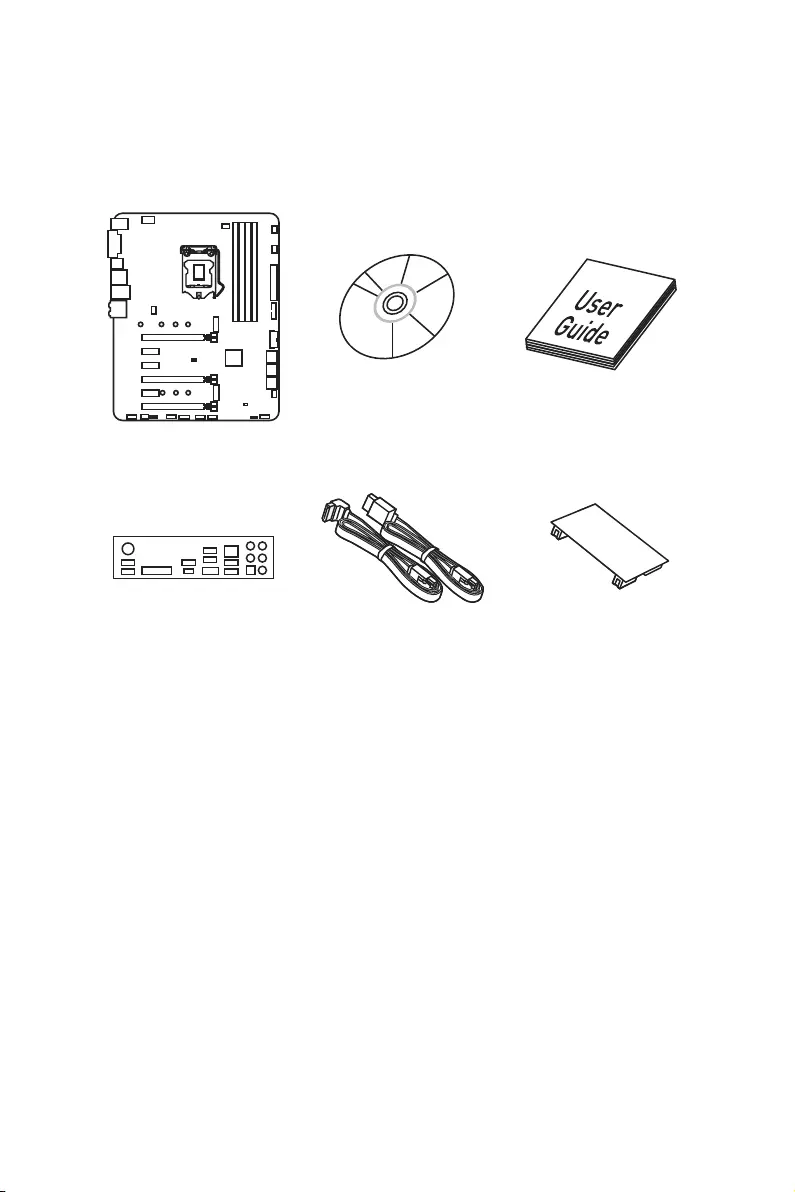
Unpacking
Unpacking
Thank you for buying the MSI® Z370 SLI PLUS motherboard. Check to make sure your
motherboard box contains the following items. If something is missing, contact your
dealer as soon as possible.
SATA Cable x2
Drivers & Utilities
Disc Motherboard User
Guide
I/O Shield
Motherboard
SLI HB Bridge M x1

2Safety Information
Safety Information
yThe components included in this package are prone to damage from electrostatic
discharge (ESD). Please adhere to the following instructions to ensure successful
computer assembly.
yEnsure that all components are securely connected. Loose connections may cause
the computer to not recognize a component or fail to start.
yHold the motherboard by the edges to avoid touching sensitive components.
yIt is recommended to wear an electrostatic discharge (ESD) wrist strap when
handling the motherboard to prevent electrostatic damage. If an ESD wrist strap is
not available, discharge yourself of static electricity by touching another metal object
before handling the motherboard.
yStore the motherboard in an electrostatic shielding container or on an anti-static pad
whenever the motherboard is not installed.
yBefore turning on the computer, ensure that there are no loose screws or metal
components on the motherboard or anywhere within the computer case.
yDo not boot the computer before installation is completed. This could cause
permanent damage to the components as well as injury to the user.
yIf you need help during any installation step, please consult a certified computer
technician.
yAlways turn off the power supply and unplug the power cord from the power outlet
before installing or removing any computer component.
yKeep this user guide for future reference.
yKeep this motherboard away from humidity.
yMake sure that your electrical outlet provides the same voltage as is indicated on the
PSU, before connecting the PSU to the electrical outlet.
yPlace the power cord such a way that people can not step on it. Do not place anything
over the power cord.
yAll cautions and warnings on the motherboard should be noted.
yIf any of the following situations arises, get the motherboard checked by service
personnel:
Liquid has penetrated into the computer.
The motherboard has been exposed to moisture.
The motherboard does not work well or you can not get it work according to user
guide.
The motherboard has been dropped and damaged.
The motherboard has obvious sign of breakage.
yDo not leave this motherboard in an environment above 60°C (140°F), it may damage
the motherboard.
3
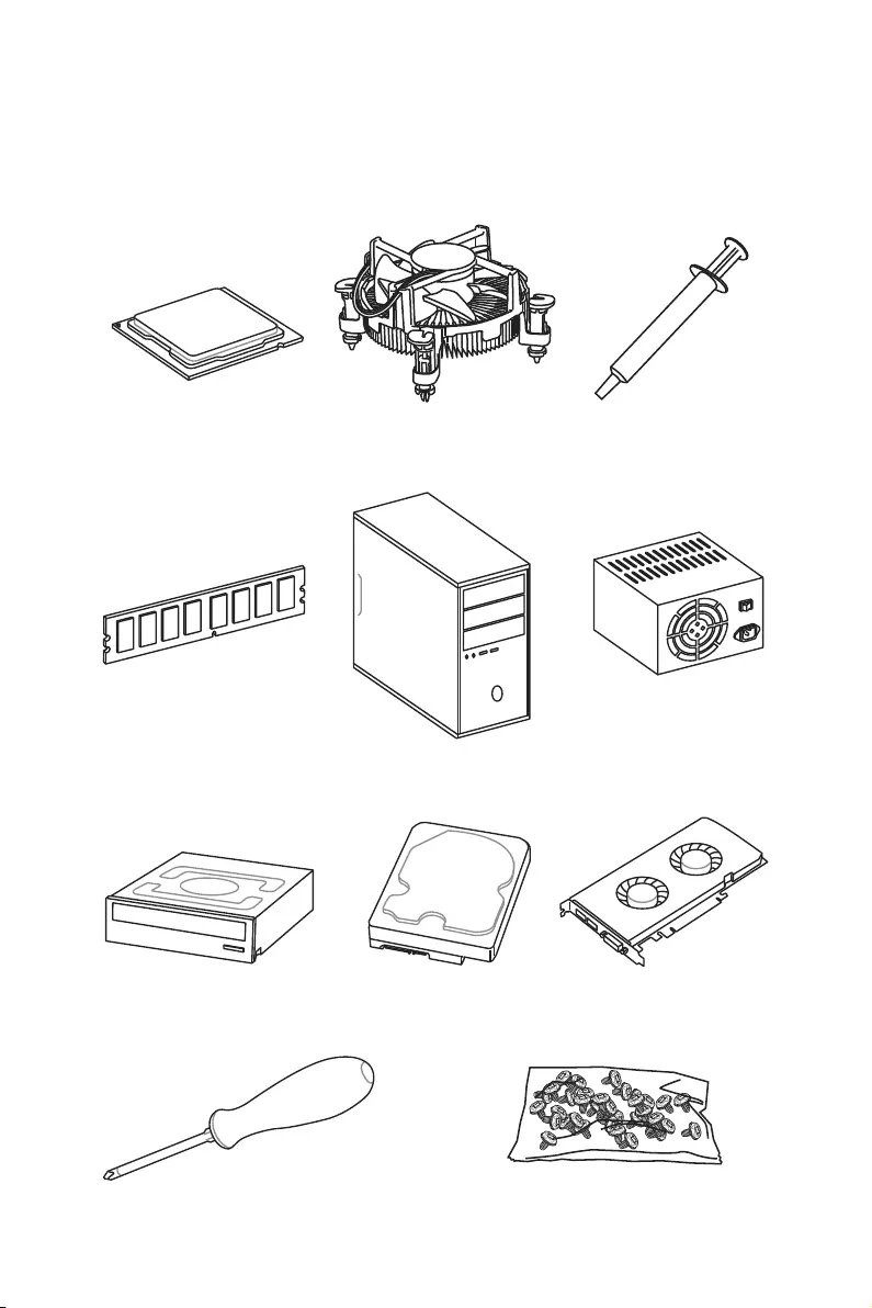
Quick Start
Intel® LGA 1151 CPU
DDR4 Memory
Graphics Card
SATA Hard Disk Drive
SATA DVD Drive
A Package of Screws
Phillips Screwdriver
Chassis
Power Supply Unit
CPU Fan Thermal Paste
Quick Start
Preparing Tools and Components
4Quick Start
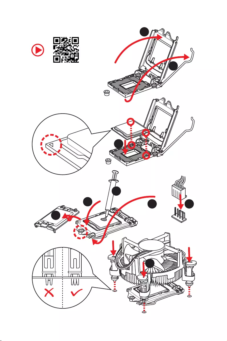
http://youtu.be/bf5La099urI
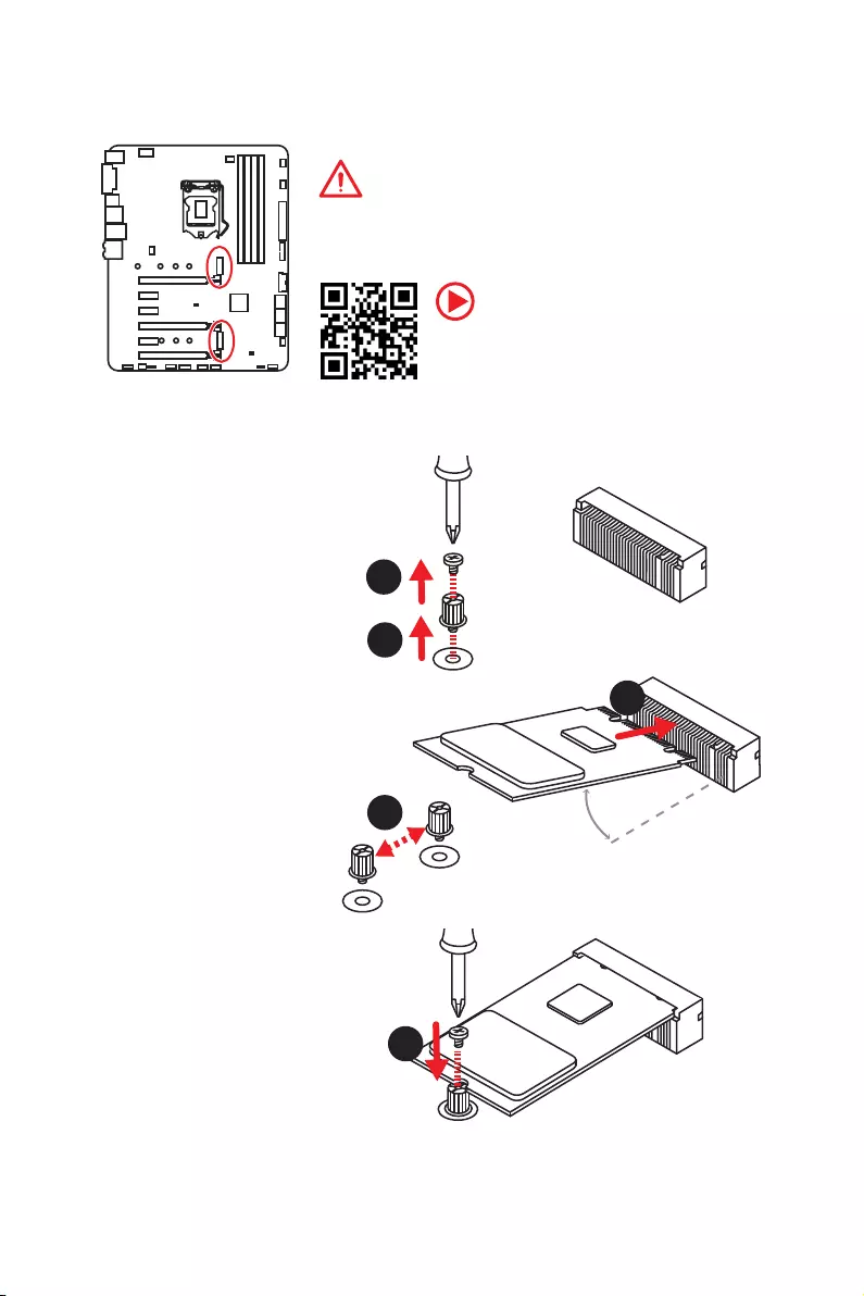
Installing a Processor
1
2
3
6
45
7
8
9
5
Quick Start
1
1
2
2
3
3
Installing DDR4 memory
DIMMB2 DIMMB2
DIMMB1
DIMMA2 DIMMA2 DIMMA2
DIMMA1
6Quick Start
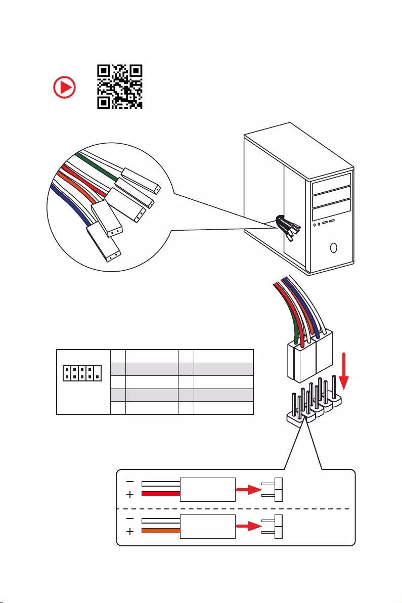
Connecting the Front Panel Header
1
2 10
9
JFP1
1 HDD LED + 2 Power LED +
3 HDD LED — 4 Power LED —
5 Reset Switch 6 Power Switch
7 Reset Switch 8 Power Switch
9 Reserved 10 No Pin
RESET SW
POWER SW
POWER LED+
POWER LED-
HDD LED
HDD LED
RESET SW
JFP1
HDD LED HDD LED —
HDD LED +
POWER LED —
POWER LED +
POWER LED
7
Quick Start
BAT1
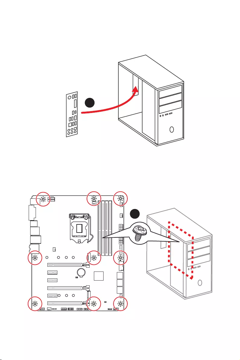
Installing the Motherboard
1
2
8Quick Start
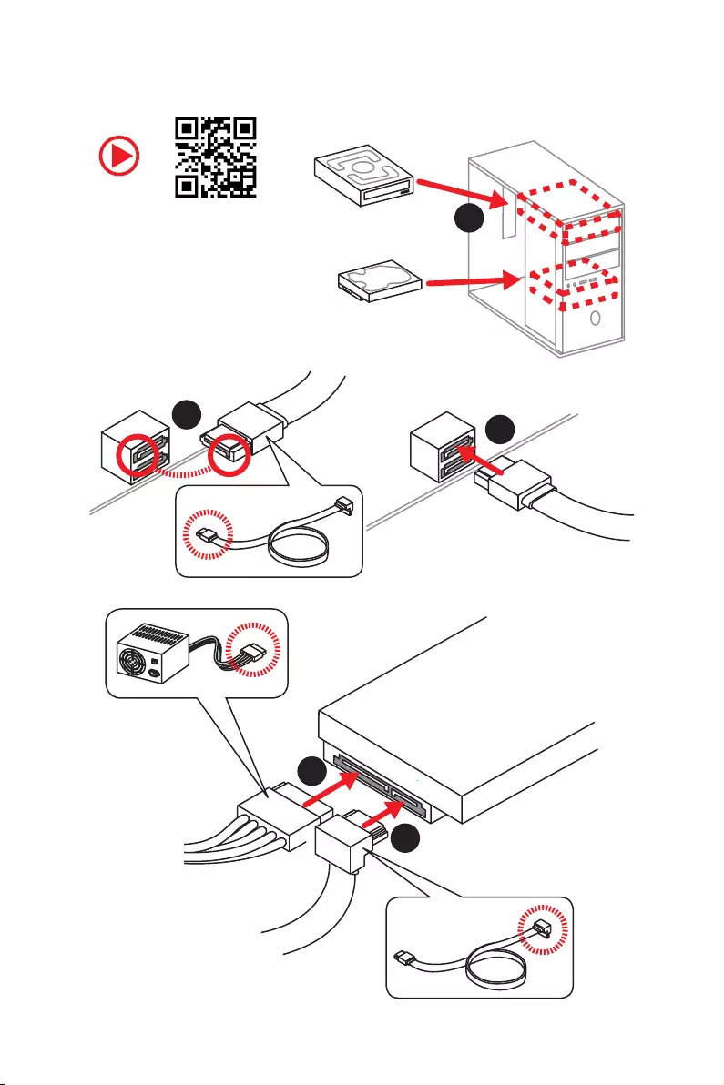
Installing SATA Drives
1
23
4
5
9
Quick Start
1
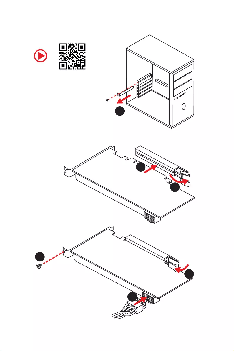
Installing a Graphics Card
2
3
4
5
6
10 Quick Start
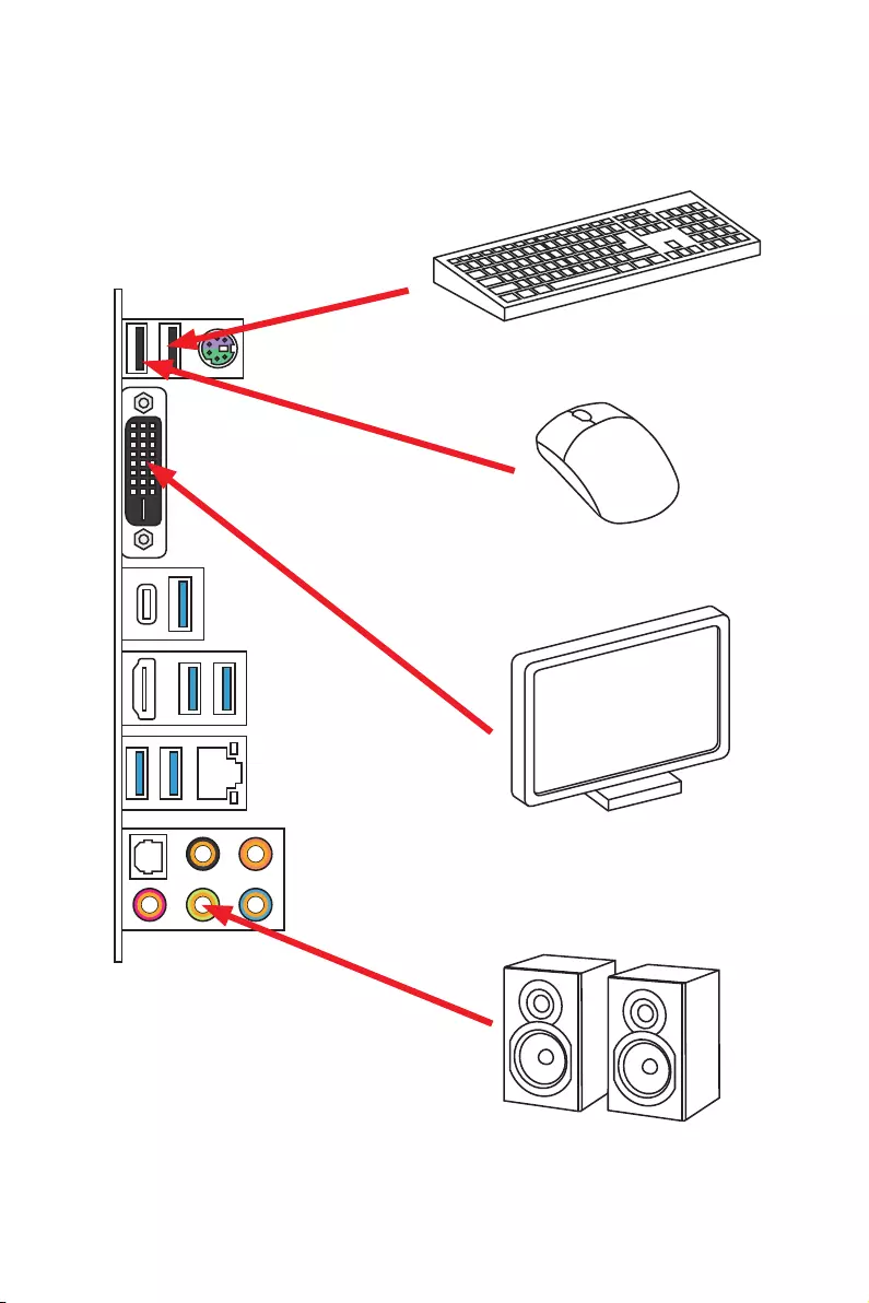
Connecting Peripheral Devices
11
Quick Start
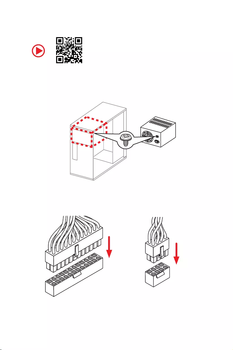
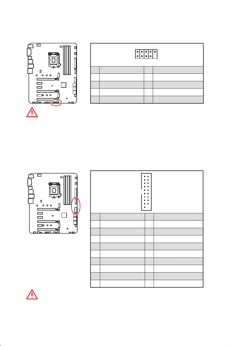
Connecting the Power Connectors
ATX_PWR1 CPU_PWR1
12 Quick Start
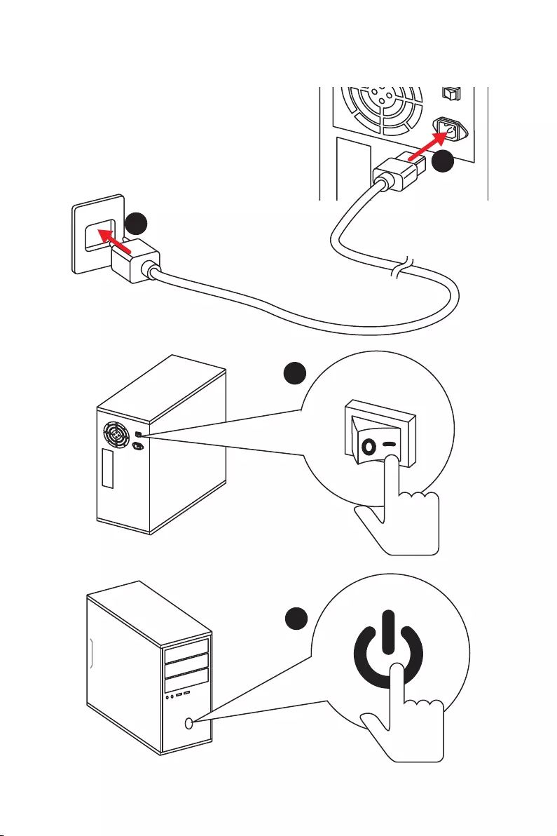
Power On
1
4
2
3

13
Contents
Contents
Unpacking ……………………………………………………………………………………………….. 1
Safety Information ……………………………………………………………………………………. 2
Quick Start ………………………………………………………………………………………………. 3
Preparing Tools and Components ……………………………………………………………….. 3
Installing a Processor ………………………………………………………………………………… 4
Installing DDR4 memory ……………………………………………………………………………. 5
Connecting the Front Panel Header …………………………………………………………….. 6
Installing the Motherboard …………………………………………………………………………. 7
Installing SATA Drives………………………………………………………………………………… 8
Installing a Graphics Card ………………………………………………………………………….. 9
Connecting Peripheral Devices …………………………………………………………………. 10
Connecting the Power Connectors …………………………………………………………….. 11
Power On………………………………………………………………………………………………… 12
Specifications …………………………………………………………………………………………. 16
Block Diagram ………………………………………………………………………………………. 21
Rear I/O Panel ……………………………………………………………………………………….. 22
LAN Port LED Status Table……………………………………………………………………….. 22
Audio Ports Configuration ………………………………………………………………………… 22
Realtek HD Audio Manager ………………………………………………………………………. 23
Overview of Components ………………………………………………………………………… 25
CPU Socket …………………………………………………………………………………………….. 27
DIMM Slots ……………………………………………………………………………………………… 28
PCI_E1~6: PCIe Expansion Slots ……………………………………………………………….. 29
M2_1~2: M.2 Slots (Key M) ……………………………………………………………………….. 31
SATA1~6: SATA 6Gb/s Connectors …………………………………………………………….. 32
JFP1, JFP2: Front Panel Connectors …………………………………………………………. 33
CPU_PWR1, ATX_PWR1: Power Connectors ………………………………………………. 34
JCOM1: Serial Port Connector ………………………………………………………………….. 34
JUSB1~2: USB 2.0 Connectors ………………………………………………………………….. 35
JUSB3~4: USB 3.1 Gen1 Connectors …………………………………………………………. 35
CPU_FAN1,SYS_FAN1~4, PUMP_FAN1: Fan Connectors ……………………………… 36
JAUD1: Front Audio Connector …………………………………………………………………. 37
JCI1: Chassis Intrusion Connector …………………………………………………………….. 37
JTPM1: TPM Module Connector ………………………………………………………………… 38
JBAT1: Clear CMOS (Reset BIOS) Jumper ………………………………………………….. 38
JRGB1: RGB LED connector ……………………………………………………………………… 39

14 Contents
Onboard LEDs ………………………………………………………………………………………… 40
EZ Debug LEDs ……………………………………………………………………………………….. 40
DIMM LEDs …………………………………………………………………………………………….. 40
PCIe x16 slot LEDs…………………………………………………………………………………… 40
BIOS Setup …………………………………………………………………………………………….. 41
Entering BIOS Setup ………………………………………………………………………………… 41
Resetting BIOS ………………………………………………………………………………………… 42
Updating BIOS …………………………………………………………………………………………. 42
EZ Mode …………………………………………………………………………………………………. 43
Advanced Mode ………………………………………………………………………………………. 45
SETTINGS ……………………………………………………………………………………………….. 46
Advanced ………………………………………………………………………………………………… 46
Boot ……………………………………………………………………………………………………….. 52
Security ………………………………………………………………………………………………….. 53
Save & Exit ……………………………………………………………………………………………… 54
OC ………………………………………………………………………………………………………….. 55
M-FLASH ……………………………………………………………………………………………….. 61
OC PROFILE ……………………………………………………………………………………………. 62
HARDWARE MONITOR ……………………………………………………………………………… 63
Software Description ………………………………………………………………………………. 64
Installing Windows® 10 …………………………………………………………………………….. 64
Installing Drivers …………………………………………………………………………………….. 64
Installing Utilities ……………………………………………………………………………………. 64
APP MANAGER ……………………………………………………………………………………….. 65
LIVE UPDATE 6 ………………………………………………………………………………………… 66
COMMAND CENTER ………………………………………………………………………………… 68
X-BOOST ………………………………………………………………………………………………… 72
MYSTICLIGHT ………………………………………………………………………………………….. 74
MSI SMART TOOL ……………………………………………………………………………………. 76
RAMDISK………………………………………………………………………………………………… 78
NETWORK MANAGER ………………………………………………………………………………. 79
Intel® Extreme Tuning Utility …………………………………………………………………….. 81
CPU-Z…………………………………………………………………………………………………….. 82
RAID Configuration …………………………………………………………………………………. 83
Using Intel® Rapid Storage Technology Option ROM ……………………………………. 83
Degraded RAID Array ………………………………………………………………………………. 86
M.2 PCIe SSD RAID ………………………………………………………………………………….. 88
Intel® Optane™ Memory Configuration …………………………………………………….. 91

15
Contents
System Requirements …………………………………………………………………………….. 91
Installing the Intel® Optane™ memory ………………………………………………………. 91
Removing the Intel® Optane™ memory ……………………………………………………… 93
Troubleshooting ………………………………………………………………………………………. 94
Troubleshooting …………………………………………………………………………………….. 95
Regulatory Notices …………………………………………………………………………………. 96

16 Specifications
Specifications
CPU ySupports 8th Gen Intel® Core™ processors, and Intel®
Pentium® and Celeron® processors for Socket LGA1151
Chipset Intel® Z370 Chipset
Memory
y4x DDR4 memory slots, support up to 64GB
ySupports 4000+(OC)/ 3866(OC)/ 3733(OC)/ 3600(OC)/
3466(OC)/ 3400(OC)/ 3333(OC)/ 3300(OC)/ 3200(OC)/ 3000(OC)
/ 2800(OC)/ 2667/ 2400/ 2133 MHz*
yDual channel memory architecture
ySupports non-ECC UDIMM memory
ySupports Intel® Extreme Memory Profile (XMP)
*Please refer to www.msi.com for more information on compatible memory.
Expansion Slots y3x PCIe 3.0 x16 slots
y3x PCIe 3.0 x1 slots
Onboard Graphics
y1x HDMI™ port, supports a maximum resolution of
4096×2160@30Hz, 4096×2160@24Hz, 2560×1600@60Hz
y1x DVI-D port, supports a maximum resolution of
1920×1200@60Hz
Multi-GPU ySupports 2-Way NVIDIA® SLI™ Technology
ySupports 3-Way AMD® CrossFire™ Technology
Storage
Intel® Z370 Chipset
y6x SATA 6Gb/s ports*
y2x M.2 slots (Key M)
Support up to PCIe 3.0 x4 and SATA 6Gb/s
Support PCIe 3.0 x4 NVMe U.2 SSD with Turbo U.2 Host
Card**
M2_1 slot supports 2242/ 2260 /2280/ 22110 storage
devices
M2_2 slot supports 2242/ 2260 /2280 storage devices
Intel® Optane™ Memory Ready***
* The SATA1, SATA5 and SATA6 ports will become unavailable with some
conditions of M.2 devices. Please refer to page 32 for M.2 & SATA combination
table.
** The Turbo U.2 Host Card is not included, please purchase separately.
*** Please refer to page 91 for Intel® Optane™ Memory Configuration.
Continued on next page

17
Specifications
Continued from previous page
RAID
Intel® Z370 Chipset
ySupports RAID 0, RAID 1, RAID 5 and RAID 10 for SATA
storage devices
ySupports RAID 0 and RAID 1 for M.2 storage devices*
* M.2 PCIe RAID volume can be created with M.2 GENIE. Please refer to page 88
for details about M.2 GENIE.
USB
yASMedia® ASM3142 Chipset
1x USB 3.1 Gen2 (SuperSpeed USB 10Gbps) Type-C port
on the back panel
1x USB 3.1 Gen2 (SuperSpeed USB 10Gbps) Type-A port
on the back panel
yIntel® Z370 Chipset
8x USB 3.1 Gen1 (SuperSpeed USB) ports (4 Type-A
ports on the back panel, 4 ports available through the
internal USB connectors)
6x USB 2.0 (High-speed USB) ports (2 Type-A ports on
the back panel, 4 ports available through the internal
USB connectors)
Audio
yRealtek® ALC1220 Codec
y7.1-Channel High Definition Audio
ySupports S/PDIF output
LAN 1x Intel I219-V Gigabit LAN controller
Back Panel
Connectors
y1x PS/2 mouse / keyboard combo port
y2x USB 2.0 ports
y1x DVI-D port
y1x USB 3.1 Gen2 Type-A port
y1x USB 3.1 Gen2 Type-C port
y4x USB 3.1 Gen1 Type-A ports
y1x HDMI™ port
y1x LAN (RJ45) port
y1x Optical S/PDIF out connector
y5x OFC audio jacks
Continued on next page

18 Specifications
Continued from previous page
Internal Connectors
y1x 24-pin ATX main power connector
y1x 8-pin ATX 12V power connector
y6x SATA 6Gb/s connectors
y2x USB 3.1 Gen1 connectors (supports additional 4 USB 3.1
Gen1 ports)
y2x USB 2.0 connectors (supports additional 4 USB 2.0
ports)
y1x 4-pin CPU fan connector
y1x 4-pin water pump fan connector
y4x 4-pin system fan connectors
y1x Front panel audio connector
y2x Front panel connectors
y1x RGB LED connector
y1x TPM module connector
y1x Chassis Intrusion connector
y1x Serial port connector
y1x Clear CMOS jumper
I/O Controller NUVOTON NCT6795 Controller Chip
Hardware Monitor
yCPU/System temperature detection
yCPU/System fan speed detection
yCPU/System fan speed control
From Factor yATX Form Factor
y12.0 in. x 9.6 in. (30.5 cm x 24.4 cm)
Continued on next page

19
Specifications
Continued from previous page
BIOS Features
y1x 128 Mb flash
yUEFI AMI BIOS
yACPI 6.0, SM BIOS 3.0
yMulti-language
Software
yDrivers
yAPP MANAGER
ySUPER CHARGER
yCOMMAND CENTER
yLIVE UPDATE 6
yMSI SMART TOOL
yRAMDISK
yDPC Latency Tuner
yFAST BOOT
yX-BOOST
yMYSTIC LIGHT
yNetwork MANAGER
yCPU-Z MSI GAMING
yIntel® Extreme Tuning Utility
yGoogle Chrome™, Google Toolbar, Google Drive
yNorton™ Internet Security Solution
Continued on next page

20 Specifications
Continued from previous page
Special Features
yAudio
Audio Boost 4
yNetwork
Intel LAN with Network Manager
yStorage
Twin Turbo M.2
yFAN
Pump Fan
Smart Fan Control
yLED
Mystic Light
Mystic Light Extension (RGB)
Mystic light SYNC
EZ DEBUG LED
yProtection
PCI-E Steel Armor
yPerformance
Multi GPU – SLI Technology
Multi GPU – CrossFire Technology
DDR4 Boost
USB with type A+C
yStability
Military Class 5
yVR
VR Ready
yBIOS
Click BIOS 5
yCertification
Quadro SLI Ready
Quadro Ready
21
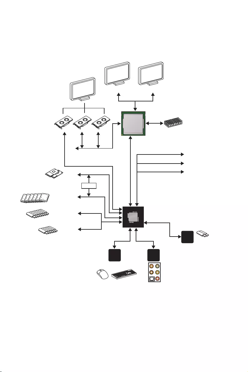
Block Diagram
Block Diagram
LPC Bus 2 x USB 3.1 Gen2
2 Channel DDR4 Memory
8 x USB 3.1 Gen1
2 x M.2
6 x USB 2.0
PCI-E Bus
PCI Express Bus
P/S2 Mouse / Keyboard Audio Jacks
DMI 3.0
Z370
CPU
NV6795
Super I/O
Realtek
ALC1220
ASMEDIA
ASM3142
x1
x1
x2
PCI Express Bus
HDMI DVI-D
Switch
x1
PCIe x1 slot
PCIe x1 slot
PCIe x1 slot
6 x SATA 6Gb/s
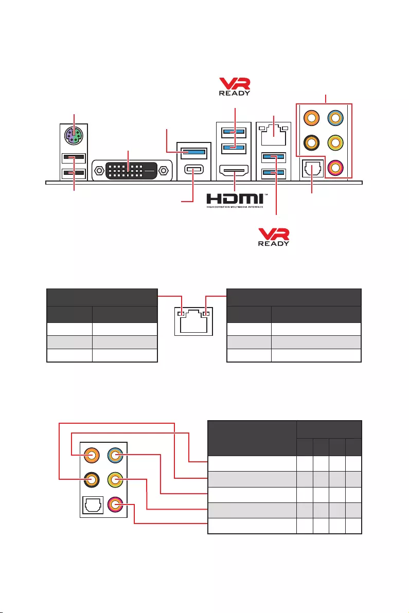
22 Rear I/O Panel
Rear I/O Panel
PS/2 Port LAN
USB 2.0
Audio Ports
DVI-D
USB 3.1 Gen1
USB 3.1 Gen2
USB 3.1 Gen1
USB 3.1 Gen2 Type-C
Link/ Activity LED
Status Description
Off No link
Yellow Linked
Blinking Data activity
Speed LED
Status Description
Off 10 Mbps connection
Green 100 Mbps connection
Orange 1 Gbps connection
LAN Port LED Status Table
Audio Ports Configuration
Audio Ports
Channel
2468
Center/ Subwoofer Out ● ●
Rear Speaker Out ●●●
Line-In/ Side Speaker Out ●
Line-Out/ Front Speaker Out ●●●●
Mic In
(●: connected, Blank: empty)
Optical S/PDIF-Out
23
Rear I/O Panel
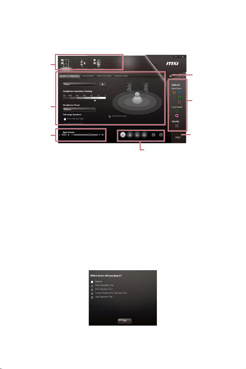
Realtek HD Audio Manager
After installing the Realtek HD Audio driver, the Realtek HD Audio Manager icon will
appear in the system tray. Double click on the icon to launch.
yDevice Selection — allows you to select a audio output source to change the related
options. The check sign indicates the devices as default.
yApplication Enhancement — the array of options will provide you a complete guidance
of anticipated sound effect for both output and input device.
yMain Volume — controls the volume or balance the right/left side of the speakers that
you plugged in front or rear panel by adjust the bar.
yProfiles — toggles between profiles.
yAdvanced Settings — provides the mechanism to deal with 2 independent audio
streams.
yJack Status — depicts all render and capture devices currently connected with your
computer.
yConnector Settings — configures the connection settings.
Auto popup dialog
When you plug into a device at an audio jack, a dialogue window will pop up asking you
which device is current connected.
Each jack corresponds to its default setting as shown on the next page.
Jack Status
Device
Selection
Connector
Strings
Profiles
Main Volume
Application
Enhancement
Advanced
Settings
24 Rear I/O Panel
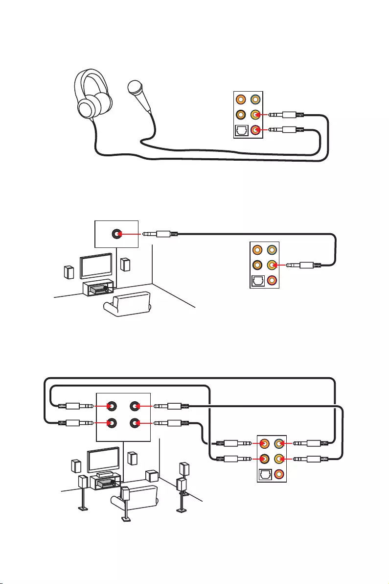
AUDIO INPUT
Rear Front
SideCenter/
Subwoofer
Audio jacks to headphone and microphone diagram
Audio jacks to stereo speakers diagram
Audio jacks to 7.1-channel speakers diagram
AUDIO INPUT
25
Overview of Components
BAT1
Overview of Components
PCI_E1
PCI_E2
JCOM1
JRGB1
PCI_E3
PCI_E4
PCI_E5
PCI_E6
CPU Socket
CPU_PWR1
ATX_PWR1
JUSB3
JUSB1
JUSB2
JBAT1
JUSB4
SATA▼1▲2
SATA▼3▲4
SATA▼5▲6
M2_1
M2_2
DIMMA1
DIMMA2
DIMMB1
DIMMB2
SYS_FAN1
SYS_FAN4
SYS_FAN3
JCI1
JFP1
JFP2
CPU_FAN1
PUMP_FAN1
JTPM1
SYS_FAN2
JAUD1

26 Overview of Components
Component Contents
Port Name Port Type Page
CPU_FAN1,SYS_FAN1~4, PUMP_FAN1 Fan Connectors 36
CPU_PWR1, ATX_PWR1 Power Connectors 34
CPU Socket LGA1151 CPU Socket 27
DIMMA1, A2, B1, B2 DIMM Slots 28
JAUD1 Front Audio Connector 37
JBAT1 Clear CMOS (Reset BIOS)
Jumper 38
JCI1 Chassis Intrusion Connector 37
JCOM1 Serial Port Connector 34
JFP1, JFP2 Front Panel Connectors 33
JRGB1 RGB LED connector 39
JTPM1 TPM Module Connector 38
JUSB1~2 USB 2.0 Connectors 35
JUSB3~4 USB 3.1 Gen1 Connectors 35
M2_1~2 M.2 Slots (Key M) 31
PCI_E1~6 PCIe Expansion Slots 29
SATA1~6 SATA 6Gb/s Connectors 32
27
Overview of Components
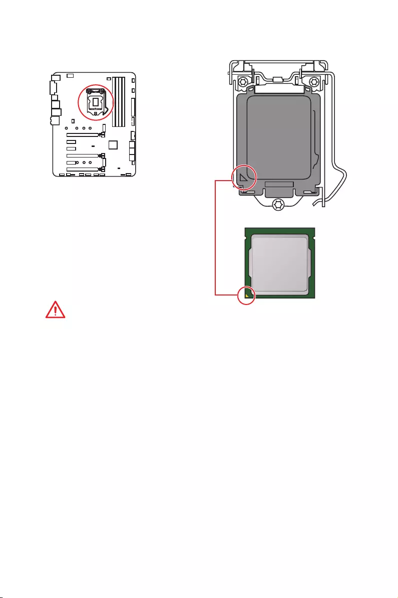
CPU Socket
Introduction to the LGA 1151 CPU
The surface of the LGA 1151 CPU has
two notches and a golden triangle to
assist in correctly lining up the CPU for
motherboard placement. The golden
triangle is the Pin 1 indicator.
Important
y
Always unplug the power cord from the power outlet before installing or removing
the CPU.
y
Please retain the CPU protective cap after installing the processor. MSI will deal with
Return Merchandise Authorization (RMA) requests if only the motherboard comes with
the protective cap on the CPU socket.
y
When installing a CPU, always remember to install a CPU heatsink. A CPU heatsink
is necessary to prevent overheating and maintain system stability.
y
Confirm that the CPU heatsink has formed a tight seal with the CPU before booting
your system.
y
Overheating can seriously damage the CPU and motherboard. Always make sure
the cooling fans work properly to protect the CPU from overheating. Be sure to apply
an even layer of thermal paste (or thermal tape) between the CPU and the heatsink to
enhance heat dissipation.
y
Whenever the CPU is not installed, always protect the CPU socket pins by covering
the socket with the plastic cap.
y
If you purchased a separate CPU and heatsink/ cooler, Please refer to the
documentation in the heatsink/ cooler package for more details about installation.
y
This motherboard is designed to support overclocking. Before attempting to
overclock, please make sure that all other system components can tolerate
overclocking. Any attempt to operate beyond product specifications is not
recommended. MSI
®
does not guarantee the damages or risks caused by inadequate
operation beyond product specifications.
28 Overview of Components
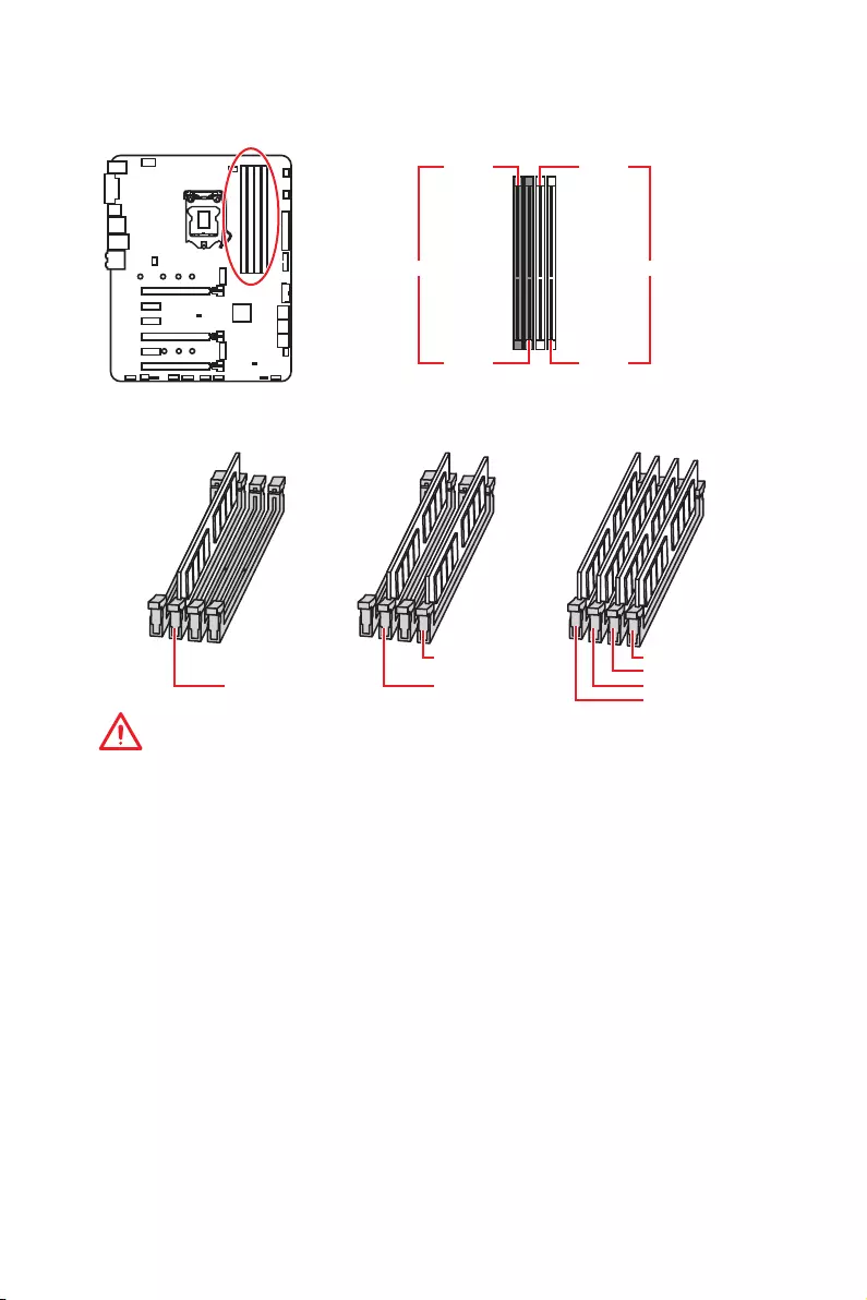
DIMM Slots
DIMMA1 DIMMB1
Channel A Channel B
DIMMA2 DIMMB2
Memory module installation recommendation
DIMMB2 DIMMB2
DIMMB1
DIMMA2 DIMMA2 DIMMA2
DIMMA1
Important
y
Always insert memory modules in the DIMMA2 slot first.
y
Due to chipset resource usage, the available capacity of memory will be a little less
than the amount of installed.
y
Based on Intel CPU specification, the Memory DIMM voltage below 1.35V is
suggested to protect the CPU.
y
Please note that the maximum capacity of addressable memory is 4GB or less
for 32-bit Windows OS due to the memory address limitation. Therefore, we
recommended that you to install 64-bit Windows OS if you want to install more than
4GB memory on the motherboard.
y
Some memory may operate at a lower frequency than the marked value when
overclocking due to the memory frequency operates dependent on its Serial Presence
Detect (SPD). Go to BIOS and find the Memory Try It! to set the memory frequency if
you want to operate the memory at the marked or at a higher frequency.
y
It is recommended to use a more efficient memory cooling system for full DIMMs
installation or overclocking.
y
The stability and compatibility of installed memory module depend on installed CPU
and devices when overclocking.
29
Overview of Components
BAT1
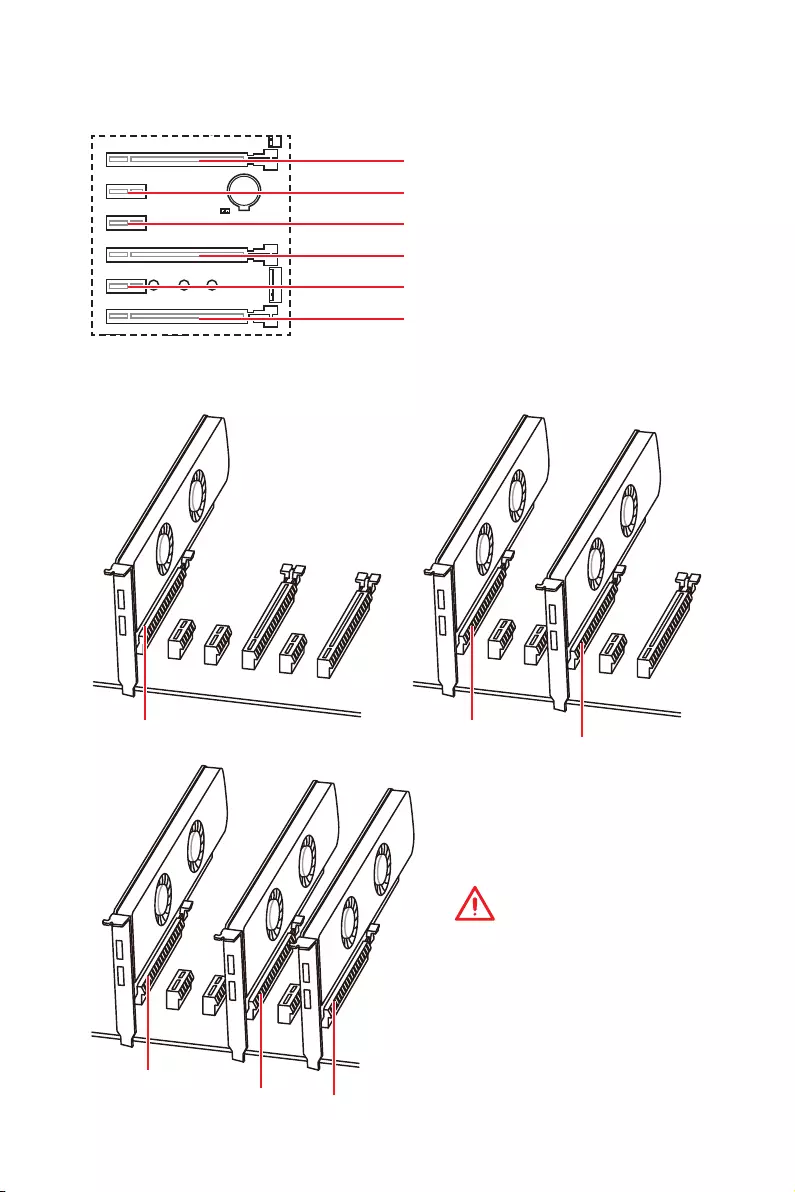
PCI_E1~6: PCIe Expansion Slots
PCI_E1: PCIe 3.0 x16 (CPU lanes)
PCI_E2: PCIe 3.0 x1 (PCH lanes)
PCI_E3: PCIe 3.0 x1 (PCH lanes)
PCI_E4: PCIe 3.0 x8 (CPU lanes)
PCI_E5: PCIe 3.0 x1 (PCH lanes)
PCI_E6: PCIe 3.0 x4 (PCH lanes)
x16 x8 x8
x8 x8 x4
Multiple graphics cards installation recommendation
Important
If you install a large and heavy
graphics card, you need to use
a tool such as MSI Gaming
Series Graphics Card Bolster to
support its weight and to prevent
deformation of the slot.
30 Overview of Components
Important
y
For a single PCIe x16 expansion card installation with optimum performance, using
the PCI_E1 slot is recommended.
y
When adding or removing expansion cards, always turn off the power supply and
unplug the power supply power cable from the power outlet. Read the expansion
card’s documentation to check for any necessary additional hardware or software
changes.
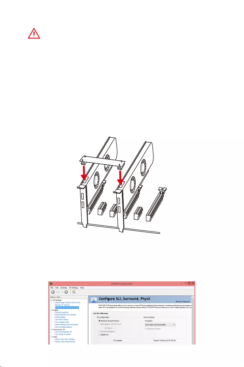
Installing SLI graphics cards
For power supply recommendations for SLI configurations, please refer to the user
guide of your graphics card to make sure you meet all the system requirements.
To install SLI graphics cards:
1. Turn off your computer and disconnect the power cord, install two graphics cards
into the PCI_E1 and PCI_E4 slots.
2. Connect the two cards together using the SLI Bridge Connector.
3. Connect all PCIe power connectors of the graphics cards.
4. Reconnect the power cord, power up the computer and install the drivers and
software included in your graphics card package.
5. Right-click the Windows desktop and select NVIDIA Control Panel from the menu,
click on Configure SLI, Surround, PhysX in the left task pane and select Maximize
3D performance in the SLI configuration menu, and then click Apply.
31
Overview of Components
Important
y
Intel
®
RST only supports PCIe M.2 SSD with UEFI ROM.
y
Intel
®
Optane
TM
Memory Ready.
Video Demonstration
Watch the video to learn how to Install M.2
module.
http://youtu.be/JCTFABytrYA
M2_1~2: M.2 Slots (Key M)
M2_1
M2_2
Installing M.2 module
1
2
330°
3. Tighten the base screw
into the hole of the
distance to the M.2 slot
as the length your M.2
module.
4. Insert your M.2 module
into the M.2 slot at a
30-degree angle.
5. Put the screw in the
notch on the trailing edge
of your M.2 module and
tighten it into the base
screw.
1. Remove the screw from
the base screw.
2. Remove the base screw.
4
5
32 Overview of Components
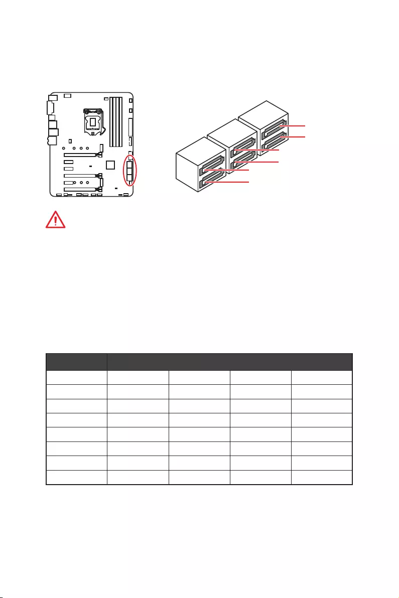
SATA1~6: SATA 6Gb/s Connectors
These connectors are SATA 6Gb/s interface ports. Each connector can connect to one
SATA device.
Important
y
The SATA1 / SATA5 port will be unavailable when an M.2 SATA SSD module has been
installed in the M2_1/ M2_2 slot.
y
The SATA5 and SATA6 ports will be unavailable when an M.2 PCIe SSD module has
been install in the M2_2 slot.
y
Please do not fold the SATA cable at a 90-degree angle. Data loss may result during
transmission otherwise.
y
SATA cables have identical plugs on either sides of the cable. However, it is
recommended that the flat connector be connected to the motherboard for space
saving purposes.
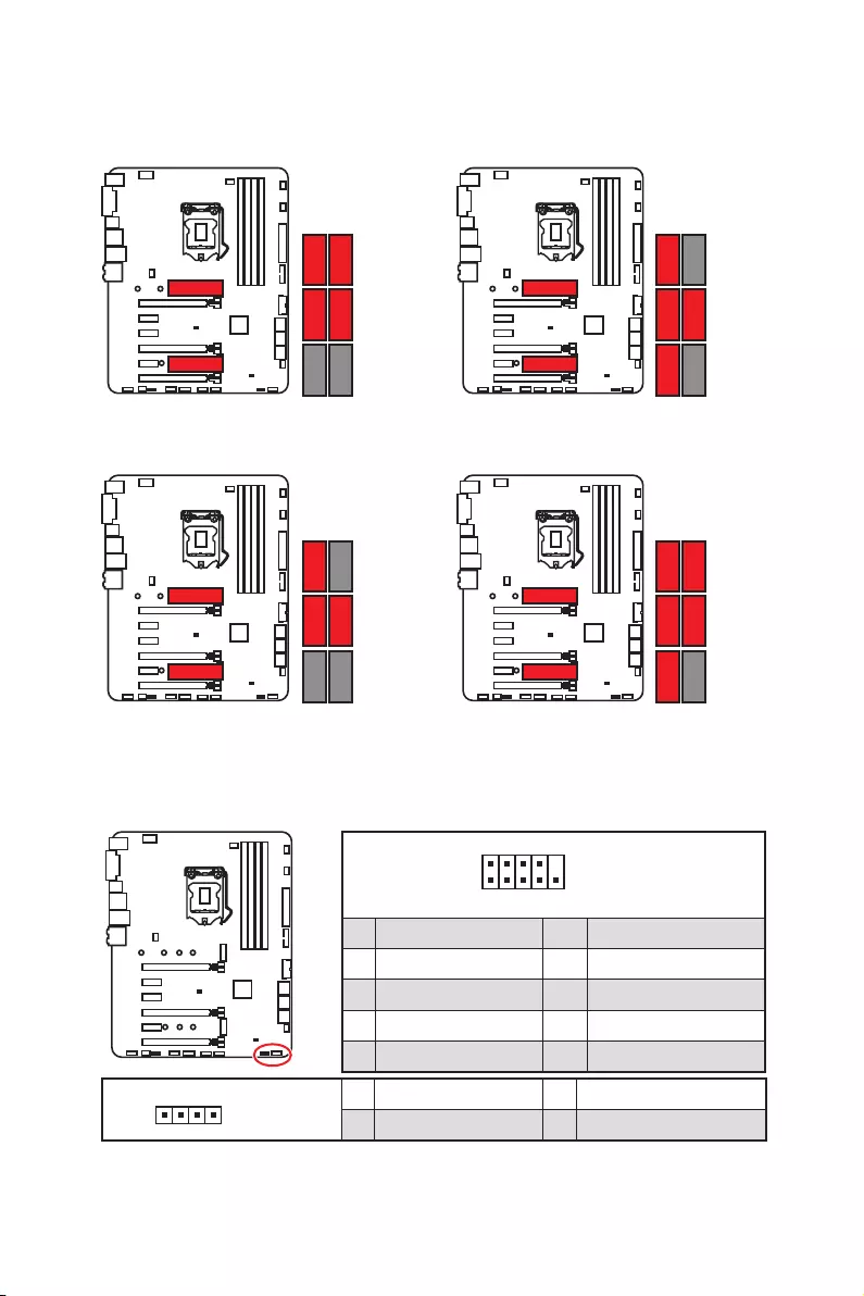
M.2 & SATA combination table
Slot Available SATA connectors
M2_1 PCIe SATA PCIe SATA
M2_2 PCIe PCIe SATA SATA
SATA1 ✓─✓─
SATA2 ✓✓✓✓
SATA3 ✓✓✓✓
SATA4 ✓✓✓✓
SATA5 ────
SATA6 ─ ─ ✓ ✓
(SATA: M.2 SATA SSD, PCIe: M.2 PCIe SSD, ✓: available, ─: unavailable)
SATA1
SATA2
SATA5
SATA6
SATA4
SATA3
33
Overview of Components
M.2 slots with examples of various combination possibilities
PCIe SATA
SATA PCIe
PCIe SATA
PCIe SATA
SATA4 SATA2
2xM.2 PCIe SSDs + 4xSATA HDDs 2xM.2 SATA SSDs + 4xSATA HDDs
1xM.2 PCIe SSD + 1xM.2 SATA SSD +
5xSATA HDDs
SATA3 SATA2
SATA1SATA4
SATA3 SATA2
SATA4
JFP1, JFP2: Front Panel Connectors
These connectors connect to the switches and LEDs on the front panel.
1
2 10
9
JFP1
1 HDD LED + 2 Power LED +
3 HDD LED — 4 Power LED —
5 Reset Switch 6 Power Switch
7 Reset Switch 8 Power Switch
9 Reserved 10 No Pin
1JFP2
1 Speaker — 2 Buzzer +
3 Buzzer — 4 Speaker +
SATA3 SATA2
SATA4
SATA6SATA3 SATA2
SATA1SATA4
SATA6
1xM.2 SATA SSD + 1xM.2 PCIe SSD +
3xSATA HDDs
34 Overview of Components
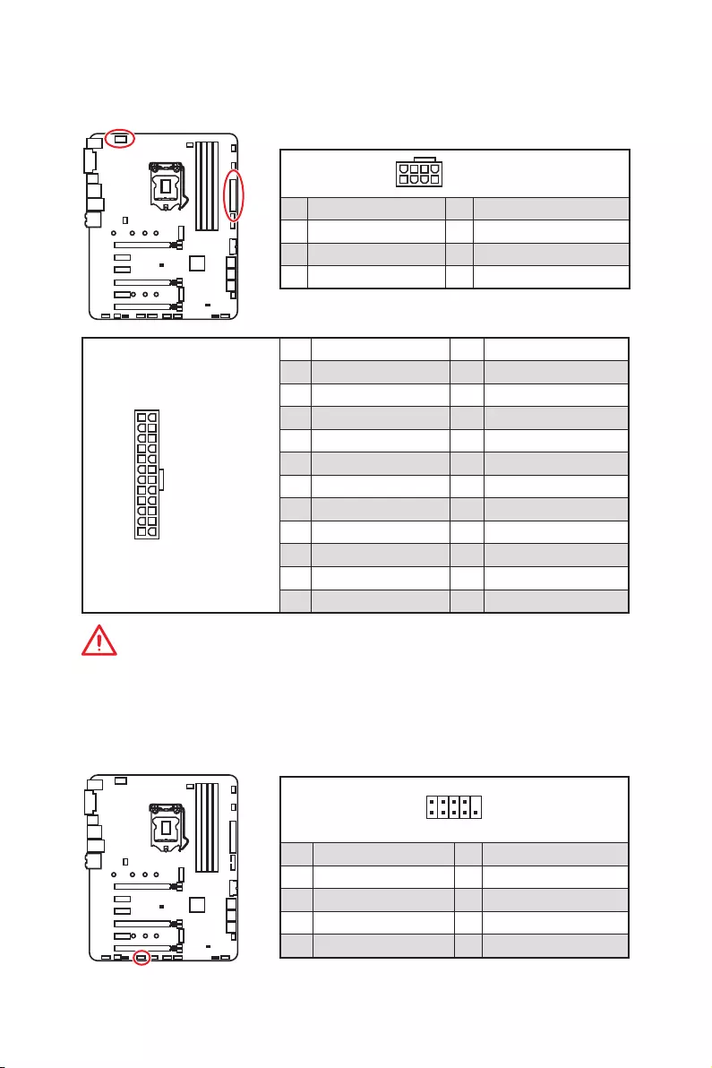
24
131
12
ATX_PWR1
1 +3.3V 13 +3.3V
2 +3.3V 14 -12V
3 Ground 15 Ground
4 +5V 16 PS-ON#
5 Ground 17 Ground
6 +5V 18 Ground
7 Ground 19 Ground
8 PWR OK 20 Res
9 5VSB 21 +5V
10 +12V 22 +5V
11 +12V 23 +5V
12 +3.3V 24 Ground
5
4 1
8CPU_PWR1
1 Ground 5 +12V
2 Ground 6 +12V
3 Ground 7 +12V
4 Ground 8 +12V
Important
Make sure that all the power cables are securely connected to a proper ATX power
supply to ensure stable operation of the motherboard.
CPU_PWR1, ATX_PWR1: Power Connectors
These connectors allow you to connect an ATX power supply.
1
2 10
9
1 DCD 2 SIN
3 SOUT 4 DTR
5 Ground 6 DSR
7 RTS 8 CTS
9 RI 10 No Pin
JCOM1: Serial Port Connector
This connector allows you to connect the optional serial port with bracket.
35
Overview of Components
JUSB3~4: USB 3.1 Gen1 Connectors
These connectors allow you to connect USB 3.1 Gen1 ports on the front panel.
1
10 11
20
1Power 11 USB2.0+
2 USB3_RX_DN 12 USB2.0-
3 USB3_RX_DP 13 Ground
4 Ground 14 USB3_TX_C_DP
5 USB3_TX_C_DN 15 USB3_TX_C_DN
6 USB3_TX_C_DP 16 Ground
7 Ground 17 USB3_RX_DP
8 USB2.0- 18 USB3_RX_DN
9 USB2.0+ 19 Power
10 NC 20 No Pin
Important
Note that the Power and Ground pins must be connected correctly to avoid possible
damage.
JUSB1~2: USB 2.0 Connectors
These connectors allow you to connect USB 2.0 ports on the front panel.
1
2 10
9
1VCC 2VCC
3 USB0- 4 USB1-
5 USB0+ 6 USB1+
7 Ground 8 Ground
9 No Pin 10 NC
Important
y
Note that the VCC and Ground pins must be connected correctly to avoid possible
damage.
y
In order to recharge your iPad,iPhone and iPod through USB ports, please install
MSI
®
SUPER CHARGER utility.
36 Overview of Components
CPU_FAN1,SYS_FAN1~4, PUMP_FAN1: Fan Connectors
Fan connectors can be classified as PWM (Pulse Width Modulation) Mode or DC Mode.
PWM Mode fan connectors provide constant 12V output and adjust fan speed with
speed control signal. DC Mode fan connectors control fan speed by changing voltage.
When you plug a 3-pin (Non-PWM) fan to a fan connector in PWM mode, the fan speed
will always maintain at 100%, which might create a lot of noise. You can follow the
instruction below to adjust the fan connector to PWM or DC Mode.
Switching fan mode and adjusting fan speed
You can switch between PWM mode and DC mode and adjust fan speed in BIOS >
HARDWARE MONITOR.
Select PWM mode or DC mode
Important
Make sure fans are working properly after switching the PWM/ DC mode.
There are gradient points of the fan speed that allow you to adjust
fan speed in relation to CPU temperature.
PWM Mode pin definition
1 Ground 2 +12V
3 Sense 4 Speed Control Signal
DC Mode pin definition
1 Ground 2 Voltage Control
3 Sense 4 NC
Pin definition of fan connectors
1
CPU_FAN1
Default PWM Mode fan connectors
Default DC Mode fan connectors
1
SYS_FAN1/ SYS_FAN3/
SYS_FAN4
SYS_FAN2
1
1
PUMP_FAN1
37
Overview of Components
JAUD1: Front Audio Connector
This connector allows you to connect audio jacks on the front panel.
1
2 10
9
1 MIC L 2 Ground
3 MIC R 4 NC
5 Head Phone R 6 MIC Detection
7 SENSE_SEND 8 No Pin
9 Head Phone L
10
Head Phone Detection
JCI1: Chassis Intrusion Connector
This connector allows you to connect the chassis intrusion switch cable.
Normal
(default)
Trigger the chassis
intrusion event
Using chassis intrusion detector
1. Connect the JCI1 connector to the chassis intrusion switch/ sensor on the chassis.
2. Close the chassis cover.
3. Go to BIOS > SETTINGS > Security > Chassis Intrusion Configuration.
4. Set Chassis Intrusion to Enabled.
5. Press F10 to save and exit and then press the Enter key to select Yes.
6. Once the chassis cover is opened again, a warning message will be displayed on
screen when the computer is turned on.
Resetting the chassis intrusion warning
1. Go to BIOS > SETTINGS > Security > Chassis Intrusion Configuration.
2. Set Chassis Intrusion to Reset.
3. Press F10 to save and exit and then press the Enter key to select Yes.
38 Overview of Components
1
2 14
13
1 LPC Clock 2
3V Standby power
3 LPC Reset 4 3.3V Power
5
LPC address & data pin0
6 Serial IRQ
7
LPC address & data pin1
8 5V Power
9
LPC address & data pin2
10 No Pin
11
LPC address & data pin3
12 Ground
13 LPC Frame 14 Ground
JTPM1: TPM Module Connector
This connector is for TPM (Trusted Platform Module). Please refer to the TPM security
platform manual for more details and usages.
JBAT1: Clear CMOS (Reset BIOS) Jumper
There is CMOS memory onboard that is external powered from a battery located on
the motherboard to save system configuration data. If you want to clear the system
configuration, set the jumper to clear the CMOS memory.
Keep Data
(default)
Clear CMOS/
Reset BIOS
Resetting BIOS to default values
1. Power off the computer and unplug the power cord
2. Use a jumper cap to short JBAT1 for about 5-10 seconds.
3. Remove the jumper cap from JBAT1.
4. Plug the power cord and power on the computer.
39
Overview of Components
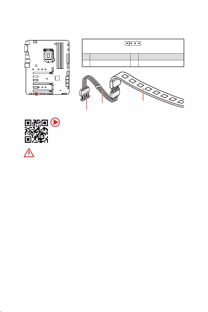
JRGB1: RGB LED connector
This connector allows you to connect the 5050 RGB LED strips.
Important
y
This connector supports 5050 RGB multi-color LED strips (12V/G/R/B) with the
maximum power rating of 3A (12V). Please keeping the LED strip shorter than 2
meters to prevent dimming.
y
Always turn off the power supply and unplug the power cord from the power outlet
before installing or removing the RGB LED strip.
y
Please use MSI’s software to control the extended LED strip.
JRGB1
Extension cable 5050 LED strip
1
1 +12V 2 G
3 R 4 B
Video Demonstration
Watch the video to learn how to install 5050 RGB LED strips to RGB LED
connector.
https://youtu.be/CqNHyADzd2Q
40 Onboard LEDs
Onboard LEDs
PCI_E1 LED
PCI_E4 LED
PCI_E6 LED
EZ Debug LEDs
These LEDs indicate the status of key components during booting process. When an
error is occurred, the corresponding LED stays lit until the problem is solved.
PCIe x16 slot LEDs
These LED indicate the PCIe x16 slots status.
CPU — indicates CPU is not detected or fail.
DRAM — indicates DRAM is not detected or fail.
VGA — indicates GPU is not detected or fail.
BOOT — indicates the booting device is not detected
or fail.
LED Color PCIe slot speed status
Red x16
White x8, x4, x1
DIMM LEDs
DIMM LEDs
These LED indicate the memory modules are installed.

41
BIOS Setup
BIOS Setup
The default settings offer the optimal performance for system stability in normal
conditions. You should always keep the default settings to avoid possible system
damage or failure booting unless you are familiar with BIOS.
Important
y
BIOS items are continuously update for better system performance. Therefore, the
description may be slightly different from the latest BIOS and should be for reference
only. You could also refer to the HELP information panel for BIOS item description.
y
The pictures in this chapter are for reference only and may vary from the product you
purchased.
Entering BIOS Setup
Please refer the following methods to enter BIOS setup.
yPress Delete key, when the Press DEL key to enter Setup Menu, F11 to enter Boot
Menu message appears on the screen during the boot process.
yUse MSI FAST BOOT application. Click on GO2BIOS button and choose OK. The
system will reboot and enter BIOS setup directly.
Click on GO2BIOS
Function key
F1: General Help
F2: Add/ Remove a favorite item
F3: Enter Favorites menu
F4: Enter CPU Specifications menu
F5: Enter Memory-Z menu
F6: Load optimized defaults
F7: Switch between Advanced mode and EZ mode
F8: Load Overclocking Profile
F9: Save Overclocking Profile
F10: Save Change and Reset*
F12: Take a screenshot and save it to USB flash drive (FAT/ FAT32 format only).
Ctrl+F: Enter Search page
* When you press F10, a confirmation window appears and it provides the modification
information. Select between Yes or No to confirm your choice.

42 BIOS Setup
Resetting BIOS
You might need to restore the default BIOS setting to solve certain problems. There are
several ways to reset BIOS:
yGo to BIOS and press F6 to load optimized defaults.
yShort the Clear CMOS jumper on the motherboard.
Important
Be sure the computer is off before clearing CMOS data. Please refer to the Clear
CMOS jumper section for resetting BIOS.
Updating BIOS
Updating BIOS with M-FLASH
Before updating:
Please download the latest BIOS file that matches your motherboard model from MSI
website. And then save the BIOS file into the USB flash drive.
Updating BIOS:
1. Insert the USB flash drive that contains the update file into the computer.
2. Press <Ctrl+F5> key.
3. Click on Yes to reboot the system and enter the flash mode.
4. Select a BIOS file to perform the BIOS update process.
5. After the flashing process is 100% completed, the system will reboot
automatically.
Updating the BIOS with Live Update 6
Before updating:
Make sure the LAN driver is already installed and the Internet connection is set
properly.
Updating BIOS:
1. Install and launch MSI LIVE UPDATE 6.
2. Select BIOS Update.
3. Click on Scan button.
4. Click on Download icon to download and install the latest BIOS file.
5. Click Next and choose In Windows mode. And then click Next and Start to start
updating BIOS.
6. After the flashing process is 100% completed, the system will restart
automatically.
43
BIOS Setup
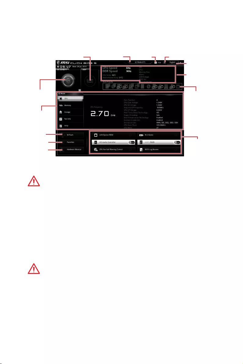
EZ Mode
At EZ mode, it provides the basic system information and allows you to configure the
basic setting. To configure the advanced BIOS settings, please enter the Advanced
Mode by pressing the Setup Mode switch or F7 function key.
Information
display
XMP switch
System
information
Boot device
priority bar
Function
buttons
Language
SearchScreenshotSetup Mode switch
M-Flash
Favorites
Hardware
Monitor
OC GENIE 4
switch
yOC GENIE 4 switch — click on it to toggle the OC GENIE 4 for OC.
Important
Please don’t make any changes in OC menu and don’t load defaults to keep the
optimal performance and system stability after activating the OC GENIE 4 function.
yXMP switch — click on the inner circle to enable/ disable the X.M.P. (Extreme Memory
Profile). Switch the outer circle to select the X.M.P. profile. This switch will only be
available if the X.M.P. supported memory module is installed.
ySetup Mode switch — press this tab or the F7 key to switch between Advanced mode
and EZ mode.
yScreenshot — click on this tab or the F12 key to take a screenshot and save it to USB
flash drive (FAT/ FAT32 format only).
ySearch — click on this tab or the Ctrl+F keys and the search page will show. It allows
you to search by BIOS item name, enter the item name to find the item listing. Move
the mouse over a blank space and right click the mouse to exit search page.
Important
In search page, only the F6, F10 and F12 function keys are available.
yLanguage — allows you to select the language of BIOS setup.
ySystem information — shows the CPU/ DDR speed, CPU/ MB temperature, MB/ CPU
type, memory size, CPU/ DDR voltage, BIOS version and build date.
yBoot device priority bar — you can move the device icons to change the boot priority.
The boot priority from high to low is left to right.

44 BIOS Setup
yInformation display — click on the CPU, Memory, Storage, Fan Info and Help buttons
on left side to display related information.
yFunction buttons — enable or disable the LAN Option ROM, M.2/ Optane Genie, HD
audio controller, AHCI, RAID, CPU Fan Fail Warning Control and BIOS Log Review by
clicking on their respective button.
yM-Flash — click on this button to display the M-Flash menu that provides the way to
update BIOS with a USB flash drive.
yHardware Monitor — click on this button to display the Hardware Monitor menu that
allows you to manually control the fan speed by percentage.
yFavorites menu — press the F3 key to enter Favorites menu. It allows you to create
personal BIOS menu where you can save and access favorite/ frequently-used BIOS
setting items.
Default HomePage — allows you to select a BIOS menu (e.g. SETTINGS, OC…,etc)
as the BIOS home page.
Favorite1~5 — allows you to add the frequently-used/ favorite BIOS setting items
in one page.
To add a BIOS item to a favorite page (Favorite 1~5)
1. Move the mouse over a BIOS item not only on BIOS menu but also on search
page.
2. Right-click or press F2 key.
3. Choose a favorite page and click on OK.
To delete a BIOS item from favorite page
1. Move the mouse over a BIOS item on favorite page (Favorite 1~5)
2. Right-click or press F2 key.
3. Choose Delete and click on OK.
45
BIOS Setup
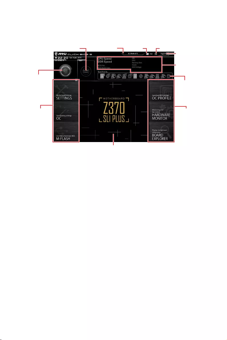
Advanced Mode
Press Setup Mode switch or F7 function key can switch between EZ Mode and
Advanced Mode in BIOS setup.
OC GENIE 4
switch
XMP switch
System
information
Boot device
priority bar
BIOS menu
selection
Language
SearchScreenshotSetup Mode switch
Menu display
BIOS menu
selection
yOC GENIE 4 switch/ XMP switch/ Setup Mode switch/ Screenshot/ Language/
System information/ Boot device priority bar — please refer to the descriptions of EZ
Mode Overview section.
yBIOS menu selection — the following options are available:
SETTINGS — allows you to specify the parameters for chipset and boot devices.
OC — allows you to adjust the frequency and voltage. Increasing the frequency may
get better performance.
M-FLASH — provides the way to update BIOS with a USB flash drive.
OC PROFILE — allows you to manage overclocking profiles.
HARDWARE MONITOR — allows you to set the speeds of fans and monitor voltages
of system.
BOARD EXPLORER — provides the information of installed devices on this
motherboard.
yMenu display — provides BIOS setting items and information to be configured.
46 BIOS Setup
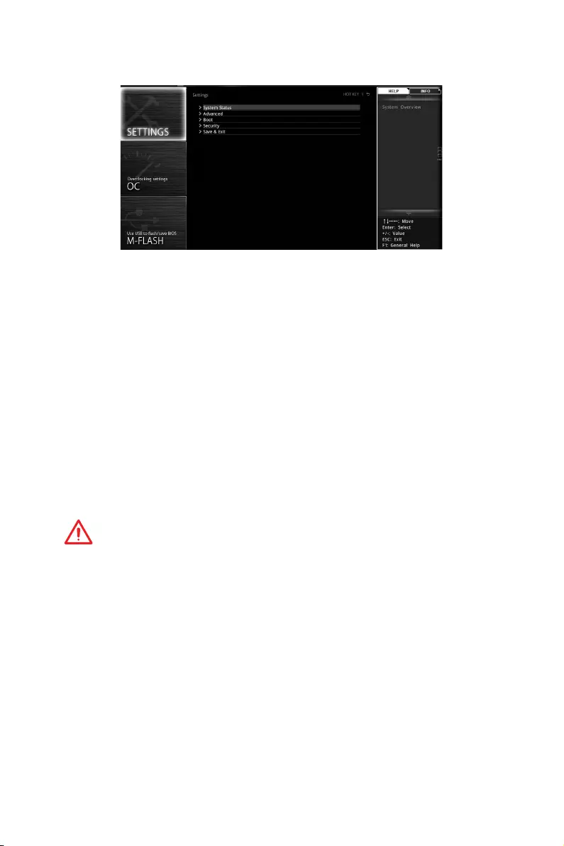
SETTINGS
System Status
fSystem Date
Sets the system date. Use tab key to switch between date elements.
The format is <day> <month> <date> <year>.
<day> Day of the week, from Sun to Sat, determined by BIOS. Read-only.
<month> The month from Jan. through Dec.
<date> The date from 1 to 31 can be keyed by numeric function keys.
<year> The year can be adjusted by users.
fSystem Time
Sets the system time. Use tab key to switch between time elements.
The time format is <hour> <minute> <second>.
fSATA PortX/ M2_X
Shows the information of connected SATA/ M.2 devices.
Important
If the connected SATA device is not displayed, turn off computer and re-check SATA
cable and power cable connections of the device and motherboard.
fSystem Information
Shows detailed system information, including CPU type, BIOS version, and Memory
(read only).
fDMI Information
Shows system information, desktop Board Information and chassis Information. (Read
only).
Advanced
fPCI Subsystem Settings
Sets PCI, PCI express interface protocol and latency timer. Press Enter to enter the
sub-menu.

47
BIOS Setup
fPEG X — Max Link Speed [Auto]
Sets PCI Express protocol of PCIe x16 slots for matching different installed devices.
[Auto] This item will be configured automatically by BIOS.
[Gen1] Enables PCIe Gen1 support only.
[Gen2] Enables PCIe Gen2 support only.
[Gen3] Enables PCIe Gen3 support only.
fAbove 4G memory/ Crypto Currency mining [Disabled]
Enables or disables 64-bit capable devices to be decoded in above 4G address
space. It is only available if the system supports 64-bit PCI decoding.
[Enabled] Allows you to utilize more than 4x GPUs.
[Disabled] Disables this function.
fACPI Settings
Sets ACPI parameters of onboard power LED behaviors. Press Enter to enter the sub-
menu.
fPower LED [Blinking]
Sets shining behaviors of the onboard Power LED.
[Dual Color] The power LED turns to another color to indicate the S3 state.
[Blinking] The power LED blinks to indicate the S3 state.
fIntegrated Peripherals
Sets integrated peripherals’ parameters, such as LAN, HDD, USB and audio. Press
Enter to enter the sub-menu.
fOnboard LAN Controller [Enabled]
Enables or disables the onboard LAN controller.
fLAN Option ROM [Disabled]
Enables or disables the legacy network Boot Option ROM for detailed settings. This
item will appear when Onboard LAN Controller is enabled.
[Enabled] Enables the onboard LAN Boot ROM.
[Disabled] Disables the onboard LAN Boot ROM.
fNetwork Stack [Disabled]
Sets UEFI network stack for optimizing IPv4 / IPv6 function.
[Enabled] Enables UEFI network stack.
[Disabled] Disables UEFI network stack.
fIpv4 PXE Support [Enabled]
When Enabled, the system UEFI network stack will support Ipv4 protocol. This item
will appear when Network Stack is enabled.
[Enabled] Enables the Ipv4 PXE boot support.
[Disabled] Disables the Ipv4 PXE boot support.
fIpv6 PXE Support [Enabled]
When Enabled, the system UEFI network stack will support Ipv6 protocol. This item
will appear when Network Stack is enabled.
[Enabled] Enables the Ipv6 PXE boot support.
[Disabled] Disables the Ipv6 PXE boot support.

48 BIOS Setup
fSATA Mode [AHCI Mode]
Sets the operation mode of the onboard SATA controller.
[AHCI Mode] Specify the AHCI mode for SATA storage devices. AHCI (Advanced
Host Controller Interface) offers some advanced features to enhance
the speed and performance of SATA storage device, such as Native
Command Queuing (NCQ) and hot-plugging.
[RAID Mode] Enables RAID function for SATA storage devices.
fM2_1/ M2_2-RST Pcie Storage Remapping [Disabled]
Enables or disables Intel Rapid Storage Technology for M.2 PCIe devices.
fM.2/Optane Genie [Disabled]
Enables or disables Intel RST support for M.2 SSDs or Optane memory.
fSATAx Hot Plug [Disabled]
Allows user to enable or disable the SATA hot plug support.
[Enabled] Enables hot plug support for the SATA ports.
[Disabled] Disables hot plug support for the SATA ports.
fHD Audio Controller [Enabled]
Enables or disables the onboard High Definition Audio controller.
fHPET [Enabled]
Enables or disables the HPET (High Precision Event Timers) support.
fIntel Serial I/O [Disabled]
Enables or disables the supported devices to transfer data with Intel serial
protocol.
fIntegrated Graphics Configuration
Adjusts integrated graphics settings for optimum system. Press Enter to enter the
sub-menu.
fInitiate Graphic Adapter [PEG]
Selects a graphics device as the primary boot device.
[IGD] Integrated Graphics Display.
[PEG] PCI-Express Graphics Device.
fIntegrated Graphics Share Memory [64M]
Selects a fixed amount of system memory allocated to the onboard graphics. This
item will appear when IGD Multi-Monitor is enabled.
fIGD Multi-Monitor [Disabled]
Enables or disables the multi-screen output from integrated graphics and external
graphics card. This item appears when Initiate Graphic Adapter set to PEG.
[Enabled] Enables multi-screen function for both integrated and external
graphics cards.
[Disabled] Disables this function.
fUSB Configuration
Sets the onboard USB controller and device function. Press Enter to enter the sub-
menu.

49
BIOS Setup
fUSB Controller [Enabled]
Enables or disables all USB controller.
fXHCI Hand-off [Diasbled]
Enables or disables XHCI hand-off support for the operating system without XHCI
hand-off feature.
fLegacy USB Support [Enabled]
Sets Legacy USB function support.
[Auto] The system will automatically detect if any USB device is connected
and enable the legacy USB support.
[Enabled] Enable the USB support under legacy mode.
[Disabled] The USB devices will be unavailable under legacy mode.
fSuper IO Configuration
Sets system Super I/O chip parameters including LPT and COM ports. Press Enter to
enter the sub-menu.
fSerial (COM) Port 0 Configuration
Sets detailed configuration of serial(COM) port 0. Press Enter to enter the sub-
menu.
fSerial (COM) Port 0 [Enabled]
Enables or disables serial (COM) port 0.
fSerial (COM) Port 0 Settings [Auto]
Sets serial port 0 (COM). If set to Auto, BIOS will optimize the IRQ automatically or
you can set it manually.
fPower Management Setup
Sets system Power Management of ErP and AC Power Loss behaviors. Press Enter to
enter the sub-menu.
fErP Ready [Disabled]
Enables or disables the system power consumption according to ErP regulation.
[Enabled] Optimize the system power consumption according to ErP
regulation. It will not support S4 & S5 wake up by USB, PCI and PCIe
devices.
[Disabled] Disables this function.
fRestore after AC Power Loss [Power Off]
Sets the system behaviors while encountering the AC power loss.
[Power Off] Leaves the system in power off state after restoring AC power.
[Power On] Boot up the system after restoring AC power.
[Last State] Restores the system to the previous state (power on/ power off)
before AC power loss.
fSystem Power Fault Protection [Disabled]
Enables or disables the system to boot up when detecting abnormal voltage input.
[Enabled] Protect the system from unexpected power operation and remain
the shut down status.
[Disabled] Disables this function.

50 BIOS Setup
fWindows OS Configuration
Sets Windows OS detailed configuration and behaviors. Press Enter to enter the sub-
menu.
fWindows 10 WHQL Support [Disabled]
Enables the supports for Windows 10 or disables for other operating systems.
Before enabling this item, make sure all installed devices & utilities (hardware &
software) should meet the Windows 10 requirements.
[Enabled] The system will switch to UEFI mode to meet the Windows
equirement.
[Disabled] Disables this function.
fMSI Fast Boot [Disabled]
MSI Fast Boot is the fastest way to boot the system. It will disable more devices to
speed up system boot time which is faster than the boot time of Fast Boot.
[Enabled] Enables the MSI Fast Boot function to speed up booting time. And
the following Fast Boot field will be disabled and fixed.
[Disabled] Disables MSI Fast Boot.
Important
When MSI Fast Boot is enabled, you can use MSI FAST BOOT application to enter BIOS
setup if needed. Please refer Entering BIOS Setup section for details.
fFast Boot [Enabled/ windows 10, Disabled/ windows7]
Enables or disables the fast boot feature for Windows 10. This item will only be
available when MSI Fast Boot is disabled.
[Enabled] Enables the Fast Boot configuration to accelerate system boot time.
[Disabled] Disables the Fast Boot configuration.
fInternal GOP Configuration
Manages the onboard Graphics Output Protocol (GOP). Press Enter to enter
the sub-menu. This sub-menu will appear when Windows 10 WHQL Support is
enabled.
fSecure Boot
Sets the Windows secure boot to prevent the unauthorized accessing. Press Enter
to enter the sub-menu. This sub-menu will appear when Windows 10 WHQL
Support is enabled.
fSecure Boot Support [Disabled]
Enables or disables secure boot support.
[Enabled] Enables the secure boot function and allow you to set the secure
boot settings.
[Disabled] Disables this function.
fSecure Boot Mode [Standard]
Selects the secure boot mode. This item is to select how the secure boot keys be
loaded. This item appears when Secure Boot Support is enabled.
[Standard] The system will automatically load the secure keys from BIOS.
[Custom] Allows user to configure the secure boot settings and manually load
the secure keys.

51
BIOS Setup
fKey Management
Manages the secure boot keys. Press <Enter> to enter the sub-menu. This sub-
menu will appear when Secure Boot Mode sets to Custom.
fWake Up Event Setup
Sets system wake up behaviors for different sleep modes. Press Enter to enter the
sub-menu.
fWake Up Event By [BIOS]
Selects the wake up event by BIOS or operating system.
[BIOS] Activates the following items, set wake up events of these items.
[OS] The wake up events will be defined by OS.
fResume By RTC Alarm [Disabled]
Disables or enables the system wake up by RTC Alarm.
[Enabled] Enables the system to boot up on a scheduled time/ date.
[Disabled] Disables this function.
fDate (of month) Alarm/ Time (hh:mm:ss) Alarm
Sets RTC alarm date/ Time. If Resume By RTC Alarm is set to [Enabled], the system
will automatically resume (boot up) on a specified date/hour/minute/second in
these fields (using the + and — keys to select the date & time settings).
fResume By PCI-E Device [Disabled]
Enables or disables the wake up function of installed PCI-E expansion cards,
integrated LAN controllers or USB devices which are supported by third party
integrated chips.
[Enabled] Enables the system to be awakened from the power saving modes
when activity or input signal of PCIe device is detected.
[Disabled] Disables this function.
fResume By Onboard Intel LAN [Disabled]
Enables or disables the system wake up by Onboard Intel LAN.
[Enabled] Enables the system to be awakened from the power saving modes
when activity or input signal of Intel LAN device is detected.
[Disabled] Disables this function.
fResume by USB Device [Disabled]
Enables or disables the system wake up by USB devices.
[Enabled] Enables the system to be awakened from sleep state when activity of
USB device is detected.
[Disabled] Disables this function.
fResume From S3/S4/S5 by PS/2 Mouse [Disabled]
Enables or disables the system wake up by PS/2 mouse.
[Enabled] Enables the system to be awakened from S3/ S4/ S5 state when
activity of PS/2 mouse is detected.
[Disabled] Disables this function.

52 BIOS Setup
fResume From S3/S4/S5 by PS/2 Keyboard [Disabled]
Enables or disables the system wake up by PS/2 keyboard.
[Any Key] Enables the system to be awakened from S3/ S4/ S5 state when
activity of any key on PS/2 keyboard is detected.
[Hot Key] Enables the system to be awakened from S3/ S4/ S5 state when
activity of hot key on PS/2 keyboard is detected.
[Disabled] Disables this function.
fHot Key [Ctrl+Space]
Selects a combination of keys as a hot key to wake the system. This item appears
when you set the Resume From S3/S4/S5 by PS/2 Keyboard to Hot Key.
fSecure Erase+
Enables or disables Secure Erase+ function. Secure Erase+ is the best way to
effectively wipe all data from a SSD. Please note that data of SSD will be erased after
enabling Secure Erase+.
fIntel ( R ) Ethernet Connection 1219-V -(MAC
Shows driver information and configuration of the ethernet controller parameter.
Boot
Sets the sequence of system boot devices.
fFull Screen Logo Display [Enabled]
Enables or disables to show the full screen logo while system POST.
[Enabled] Shows the logo in full screen.
[Disabled] Shows the POST messages.
fGO2BIOS [Disabled]
Allows system to enter BIOS setup directly by pressing the Power button for 4 sec pon
bootup.
[Enabled] The system boots straight to the BIOS setup by long pressing the power
button about 4 seconds when the system is off.
[Disabled] Disables this function.
fBootup NumLock State [On]
Select the keyboard NumLock state upon bootup.
fInfo Block effect [Unlock]
Sets the state of Help information block.
[Unlock] Sliding effect.
[Lock] Fix the Help information block on the screen.
fAUTO CLR_CMOS [Disabled]
Enables or disables the CMOS data to be resumed automatically when the booting
process hang-up over 5 seconds.

53
BIOS Setup
fBoot Mode Select [LEGACY+UEFI]
Sets the system boot mode from legacy or UEFI architecture depending on OS
installation requirement. This item will become un-selectable and will be configured
automatically by BIOS when Windows 10 WHQL Support is enabled.
[UEFI] Enables UEFI BIOS boot mode support only.
[LEGACY+UEFI] Enables both Legacy BIOS boot mode and UEFI BIOS boot
mode.
fFIXED BOOT ORDER Priorities
Sets device priority for system boot.
fBoot Option Priorities
These items are used to prioritize the installed boot devices.
Security
fAdministrator Password
Sets administrator password for system security. User has full rights to change the
BIOS items with administrator password. After setting the administrator password, the
state of this item will show “Installed”.
fUser Password
Sets User Password for system security. User has limited rights to change the BIOS
items with user password. This item will be available when administrator password is
set. After setting the user password, the state of this item will show “Installed”.
fPassword Check [Setup]
Selects a condition that will request the password.
[Setup] A password will be requested for entering the BIOS Setup.
[Boot] A password will be requested for booting the system.
fPassword Clear [Enabled]
Enables or disables the clear CMOS behavior to clear a set password.
[Enabled] The password will be erased after clear CMOS.
[Disabled] The password will always be kept.
Important
When selecting the Administrator / User Password items, a password box will appear
on the screen. Type the password then press <Enter>. The password typed now will
replace any previous set password from CMOS memory. You will be prompted to
confirm the password. You may also press <Esc> to abort the selection.
To clear a set password, press <Enter> when you are prompted to enter a new
password. A message will confirm the password is being disabled. Once the password
is disabled, you can enter the setup and OS without authorization.
fTrusted Computing
Sets TPM (Trusted Platform Module) function.

54 BIOS Setup
fSecurity Device Support [Disabled]
Enables or disables the TPM function to build the endorsement key for accessing
the system.
fChassis Intrusion Configuration
Press <Enter> to enter the sub-menu.
fChassis Intrusion [Disabled]
Enables or disables recording messages when the chassis is opened. This function
is ready for the chassis equips a chassis intrusion switch.
[Enabled] Once the chassis is opened, the system will record and issue a
warning message.
[Reset] Clear the warning message. After clearing the message, please
return to Enabled or Disabled.
[Disabled] Disables this funcion.
Save & Exit
fDiscard Changes and Exit
Exit BIOS setup without saving any change.
fSave Changes and Reboot
Save all changes and reboot the system.
fSave Changes
Save current changes.
fDiscard Changes
Discard all changes and restore to the previous values.
fRestore Defaults
Restore or load all default values.
fBoot Override
The installed bootable devices will appear on this menu, you can select one of them to
be the boot device.

55
BIOS Setup
OC
Important
y
Overclocking your PC manually is only recommended for advanced users.
y
Overclocking is not guaranteed, and if done improperly, it could void your warranty or
severely damage your hardware.
y
If you are unfamiliar with overclocking, we advise you to use OC GENIE 4 function for
easy overclocking.
fOC Explore Mode [Normal]
Enables or disables to show the normal or expert version of OC settings.
[Normal] Provides the regular OC settings in BIOS setup.
[Expert] Provides the advanced OC settings for OC expert to configure in BIOS
setup.
Note: We use * as the symbol for the OC settings of Expert mode.
fCPU Ratio Apply Mode [All Core]*
Sets applied mode for CPU ratio. This item only appears when a CPU that supports
Turbo Boost is installed.
[All Core] Activate the CPU Ratio field. All CPU cores will run the same CPU ratio
that be set in CPU Ratio.
[Per Core] Activate the X-Core Ratio Limit field. Sets each CPU core ratio
separately in X-Core Ratio Limit.
fCPU Ratio [Auto]
Sets the CPU ratio that is used to determine CPU clock speed. This item can only be
changed if the processor supports this function.
f1/2/3/4-Core Ratio Limit [Auto]*
Allows you to set the CPU ratios for different number of active cores. These items only
appear when a CPU that support this function is installed.
fAdjusted CPU Frequency
Shows the adjusted CPU frequency. Read-only.

56 BIOS Setup
fCPU Ratio Mode [Dynamic Mode]*
Selects the CPU Ratio operating mode. This item will appear when you set the CPU
ratio manually.
[Fixed Mode] Fixes the CPU ratio.
[Dynamic Mode] CPU ratio will be changed dynamically according to the CPU
loading.
fRing Ratio [Auto]
Sets the ring ratio. The valid value range depends on the installed CPU.
fAdjusted Ring Frequency
Shows the adjusted Ring frequency. Read-only.
fGT Ratio [Auto]
Sets the integrated graphics ratio. The valid value range depends on the installed
CPU.
fAdjusted GT Frequency
Shows the adjusted integrated graphics frequency. Read-only.
fMisc Setting*
Press Enter, + or — key to open or close the following 3 items related to CPU features.
fEIST [Enabled]*
Enables or disables the Enhanced Intel® SpeedStep Technology.
[Enabled] Enables the EIST to adjust CPU voltage and core frequency
dynamically. It can decrease average power consumption and
average heat production.
[Disabled] Disables EIST.
fIntel Turbo Boost [Enabled]*
Enables or disables the Intel® Turbo Boost. This item appears when the installed
CPU supports this function.
[Enabled] Enables this function to boost CPU performance automatically above
rated specifications when system request the highest performance
state.
[Disabled] Disables this function.
fCPU Base Clock (MHz)
Sets the CPU Base clock. You may overclock the CPU by adjusting this value. Please
note that overclocking behavior and stability is not guaranteed. This item appears
when the installed processor supports this function.
fCPU Base Clock Apply Mode [Auto]*
Sets the applying mode for adjusted CPU base clock.
[Auto] This setting will be configured automatically by BIOS.
[Next Boot] CPU will run the adjusted CPU base clock at next boot.
[Immediate] CPU runs the adjusted CPU base clock immediately.
[During Boot] CPU will run the adjusted CPU base clock during boot.

57
BIOS Setup
fExtreme Memory Profile (X.M.P.) [Disabled]
X.M.P. (Extreme Memory Profile) is the overclocking technology by memory module.
Please enable XMP or select a profile of memory module for overclocking the memory.
This item will be available when the memory modules that support X.M.P. is installed.
fDRAM Reference Clock [Auto]*
Sets the DRAM reference clock. The valid value range depends on the installed CPU.
This item appears when a CPU that supports this adjustment is installed.
fDRAM Frequency [Auto]
Sets the DRAM frequency. Please note the overclocking behavior is not guaranteed.
fAdjusted DRAM Frequency
Shows the adjusted DRAM frequency. Read-only.
fMemory Try It ! [Disabled]
It improve memory compatibility or performance by choosing optimized memory
preset.
fAdvanced DRAM Configuration
Press Enter to enter the sub-menu. User can set the memory timing for each/ all
memory channel. The system may become un-stable or un-bootable after changing
memory timing. If it occurs, please clear the CMOS data and restore the default
settings. (Refer to the Clear CMOS jumper/ button section to clear the CMOS data, and
enter the BIOS to load the default settings.)
fMemory Fast Boot [Auto]*
Enables or disables the initiation and training for memory every booting.
[Auto] The setting will be configured automatically by BIOS.
[Enabled] System will completely keep the archives of first intiation and training
for memory. So the memory will not be initialed and trained when
booting to accelerate the system booting time.
[Disabled] The memory will be initialed and trained every booting.
fCPU Core/ GT Voltage Mode [Auto]*
Selects the control mode for CPU Core/ GT voltages.
[Auto] This setting will be configured automatically by BIOS.
[Adaptive Mode] Sets the adaptive voltage automatically for optimizing the system
performance.
[Override Mode] Allows you to set the voltage manually.
[Offset Mode] Allows you to set the offset voltage and select the voltage offset
mode.
[Adaptive + Offset ] Sets the adaptive voltage automatically and allows you to set the
offset voltage.
[Override + Offset ] Allows you to set the voltage and the offset voltage manually.
fCPU Voltages control [Auto]
These options allows you to set the voltages related to CPU. If set to Auto, BIOS will
set these voltages automatically or you can set it manually.

58 BIOS Setup
fDRAM Voltages control [Auto]
These options allows you to set the voltages related to memory. If set to Auto, BIOS
will set these voltages automatically or you can set it manually.
fPCH Voltages control [Auto] (optional)
These options allows you to set the voltages related to PCH. If set to Auto, BIOS will
set these voltages automatically or you can set it manually.
fOC Quick View Timer [3 Sec]*
Sets the duration of OC setting values showed on the screen.
fCPU Specifications
Press Enter to enter the sub-menu. This sub-menu displays the information of
installed CPU. You can also access this information menu at any time by pressing [F4].
Read only.
fCPU Technology Support
Press Enter to enter the sub-menu. The sub-menu shows the key features of
installed CPU. Read only.
fMEMORY-Z
Press Enter to enter the sub-menu. This sub-menu displays all the settings and
timings of installed memory. You can also access this information menu at any time by
pressing [F5].
fDIMMA1/A2/B1/B2 Memory SPD
Press Enter to enter the sub-menu. The sub-menu displays the information of
installed memory. Read only.
fCPU Features
Press Enter to enter the sub-menu.
fHyper-Threading [Enabled]
Intel Hyper-Threading technology treats the multi cores inside the processor as
multi logical processors that can execute instructions simultaneously. In this way,
the system performance is highly improved. This item appears when the installed
CPU supports this technology.
[Enable] Enables Intel Hyper-Threading technology.
[Disabled] Disables this item if the system does not support HT function.
fActive Processor Cores Control [All]
Allows you to select the number of active CPU cores.
fLimit CPUID Maximum [Disabled]
Enables or disables the extended CPUID value.
[Enabled] BIOS limits the maximum CPUID input value to circumvent boot
problems with older operating system that do not support the
processor with extended CPUID value.
[Disabled] Use the actual maximum CPUID input value.

59
BIOS Setup
fIntel Virtualization Tech [Enabled]
Enables or disables Intel Virtualization technology.
[Enabled] Enables Intel Virtualization technology and allows a platform to run
multiple operating systems in independent partitions. The system
can function as multiple systems virtually.
[Disabled] Disables this function.
fIntel VT-D Tech [Disabled]
Enables or disables Intel VT-D (Intel Virtualization for Directed I/O) technology.
fHardware Prefetcher [Enabled]
Enables or disables the hardware prefetcher (MLC Streamer prefetcher).
[Enabled] Allows the hardware prefetcher to automatically pre-fetch data
and instructions into L2 cache from memory for tuning the CPU
performance.
[Disabled] Disables the hardware prefetcher.
fAdjacent Cache Line Prefetch [Enabled]
Enables or disables the CPU hardware prefetcher (MLC Spatial prefetcher).
[Enabled] Enables adjacent cache line prefetching for reducing the cache
latency time and tuning the performance to the specific application.
[Disabled] Enables the requested cache line only.
fCPU AES Instructions [Enabled]
Enables or disables the CPU AES (Advanced Encryption Standard-New
Instructions) support. This item appears when a CPU supports this function.
fIntel Adaptive Thermal Monitor [Enabled]
Enables or disables the Intel adaptive thermal monitor function to protect the CPU
from overheating.
[Enabled] Throttles down the CPU core clock speed when the CPU is over the
adaptive temperature.
[Disabled] Disables this function.
fIntel C-State [Auto]
Enables or disables the Intel C-state. C-state is a processor power management
technology defined by ACPI.
[Auto] This setting will be configured automatically by BIOS.
[Enabled] Detects the idle state of system and reduce CPU power consumption
accordingly.
[Disabled] Disable this function.
fC1E Support [Disabled]
Enables or disables the C1E function for power-saving in halt state. This item
appears when Intel C-State is enabled.
[Enabled] Enables C1E function to reduce the CPU frequency and voltage for
power-saving in halt state.
[Disabled] Disables this function.

60 BIOS Setup
fPackage C State limit [Auto]
This item allows you to select a CPU C-state level for power-saving when system is
idle. The options of C-state depend on the installed CPU. This item appears when
Intel C-State is enabled.
fCFG Lock [Enabled]
Lock or un-lock the MSR 0xE2[15], CFG lock bit.
[Enabled] Locks the CFG lock bit.
[Disabled] Un-locks the CFG lock bit.
fEIST [Enabled]
Enables or disables the Enhanced Intel® SpeedStep Technology. This item will
appear when OC Explore Mode is set to Normal.
[Enabled] Enables the EIST to adjust CPU voltage and core frequency
dynamically. It can decrease average power consumption and
average heat production.
[Disabled] Disables EIST.
fIntel Turbo Boost [Enabled]
Enables or disables the Intel® Turbo Boost. This item is for Normal mode and
appears when a CPU that support Turbo Boost is installed.
[Enabled] Enables this function to boost CPU performance automatically over
specification when system request the highest performance state.
[Disabled] Disables this function.
fLong Duration Power Limit (W) [Auto]
Sets the long duration TDP power limit for CPU in Turbo Boost mode.
fLong Duration Maintained (s) [Auto]
Sets the maintaining time for Long duration power Limit(W).
fShort Duration Power Limit (W) [Auto]
Sets the short duration TDP power limit for CPU in Turbo Boost mode.
fCPU Current Limit (A) [Auto]
Sets maximum current limit of CPU package in Turbo Boost mode. When the
current is over the specified value, the CPU will automatically reduce the core
frequency for reducing the current.
fFCLK Frequency [Auto]
Sets FCLK frequency. Lower FCLK frequency may help you to set higher base clock
frequency.
fDMI Link Speed [Auto]
Sets DMI speed.
fSW Guard Extensions (SGX) [Software Control]
Enables or disables Intel SGX.
61
BIOS Setup
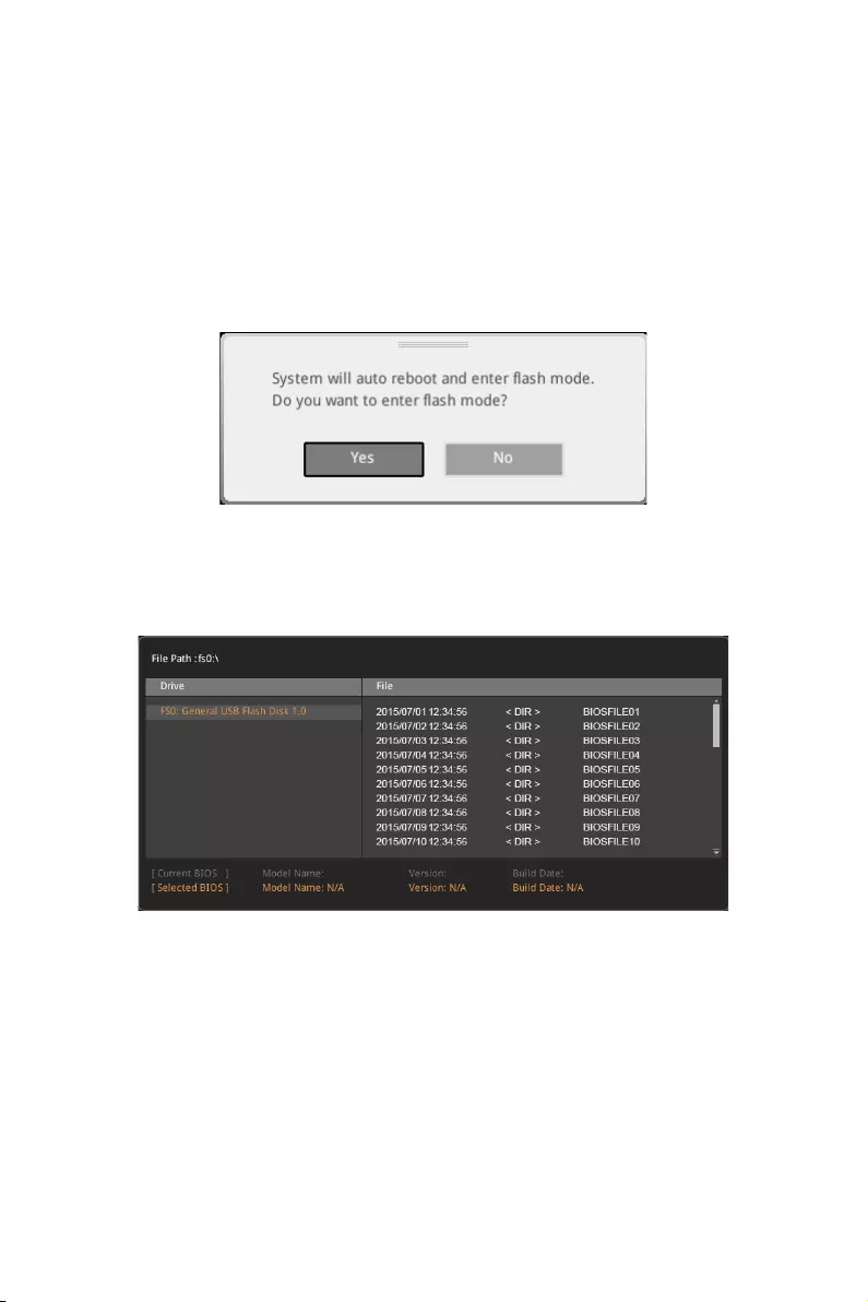
M-FLASH
M-FLASH provides the way to update BIOS with a USB flash drive. Please down-load
the latest BIOS file that matches your motherboard model from MSI website, save the
BIOS file into your USB flash drive. And then follow the steps below to update BIOS.
1. Insert the USB flash drive that contains the update file into the computer.
2. Click on M-FLASH tab on BIOS setup screen or press <Ctrl+F5> during POST,
a demand message will be prompted. Click on Yes to reboot and enter the flash
mode.
3. The system will enter the flash mode and a file selection menu will appear after
rebooting.
4. Select a BIOS file to perform the BIOS update process.
5. After the flashing process is 100% completed, the system will reboot
automatically.

62 BIOS Setup
OC PROFILE
fOverclocking Profile 1/ 2/ 3/ 4/ 5/ 6
Overclocking Profile 1/ 2/ 3/ 4/ 5/ 6 management. Press <Enter> to enter the sub-
menu.
fSet Name for Overclocking Profile 1/ 2/ 3/ 4/ 5/ 6
Name the current overclocking profile.
fSave Overclocking Profile 1/ 2/ 3/ 4/ 5/ 6
Save the current overclocking profile.
fLoad Overclocking Profile 1/ 2/ 3/ 4/ 5/ 6
Load the current overclocking profile.
fClear Overclocking Profile 1/ 2/ 3/ 4/ 5/ 6
Clear the current overclocking profile.
fOC Profile Load from ROM
Load OC profile from BIOS ROM.
fOC Profile Save to USB
Save OC profile to the USB flash drive. The USB flash drive should be FAT/ FAT32
format only.
fOC Profile Load from USB
Load OC profile from the USB flash drive. The USB flash drive should be FAT/ FAT32
format only.
63
BIOS Setup
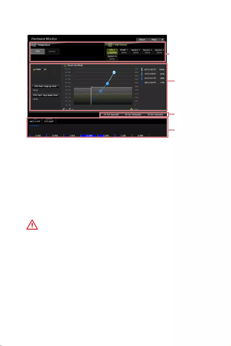
HARDWARE MONITOR
Temperature
& Speed
Fan Manage
Voltage
display
Setting
Buttons
fTemperature & Speed
Shows the current CPU temperature, system temperature and fans’ speeds.
fFan Manage
PWM — allows you to select the PWM mode for fan operation.
DC — allows you to select the DC mode for fan operation.
Fan step up/ down time — allows you to set the period of fan step up/ down.
Smart Fan Mode field — allows you to drag the gradient points to configure
the fan target values for Smart Fan mode. Smart Fan can control the fan speed
automatically depending on the CPU temperature to keep it with in a specific range.
If the current CPU temperature reaches to the target value, the Smart Fan function
will be activated.
Important
y
The changing will achieve after you save the changes and reboot the system.
y
Make sure fans are working properly after switching the PWM/ DC mode.
fSettings Buttons
All Full Speed — configures all fans to run at full operating speed.
All Set Default — configures all fans to run at default operating speed.
All Set Cancel — discards current changes and restores previous operating fan
speeds .
fVoltage display
Shows the current voltages of CPU, system and memory.

64 Software Description
Software Description
Please download and update the latest utilities and drivers at www.msi.com
Installing Windows® 10
1. Power on the computer.
2. Insert the Windows® 10 disc into your optical drive.
3. Press the Restart button on the computer case.
4. Press F11 key during the computer POST (Power-On Self Test) to get into Boot
Menu.
5. Select your optical drive from the Boot Menu.
6. Press any key when screen shows Press any key to boot from CD or DVD…
message.
7. Follow the instructions on the screen to install Windows® 10.
Installing Drivers
1. Start up your computer in Windows® 10.
2. Insert MSI® Driver Disc into your optical drive.
3. The installer will automatically appear and it will find and list all necessary
drivers.
4. Click Install button.
5. The software installation will then be in progress, after it has finished it will
prompt you to restart.
6. Click OK button to finish.
7. Restart your computer.
Installing Utilities
Before you install utilities, you must complete drivers installation.
1. Insert MSI® Driver Disc into your optical drive.
2. The installer will automatically appear.
3. Click Utilities tab.
4. Select the utilities you want to install.
5. Click Install button.
6. The utilities installation will then be in progress, after it has finished it will prompt
you to restart.
7. Click OK button to finish.
8. Restart your computer.
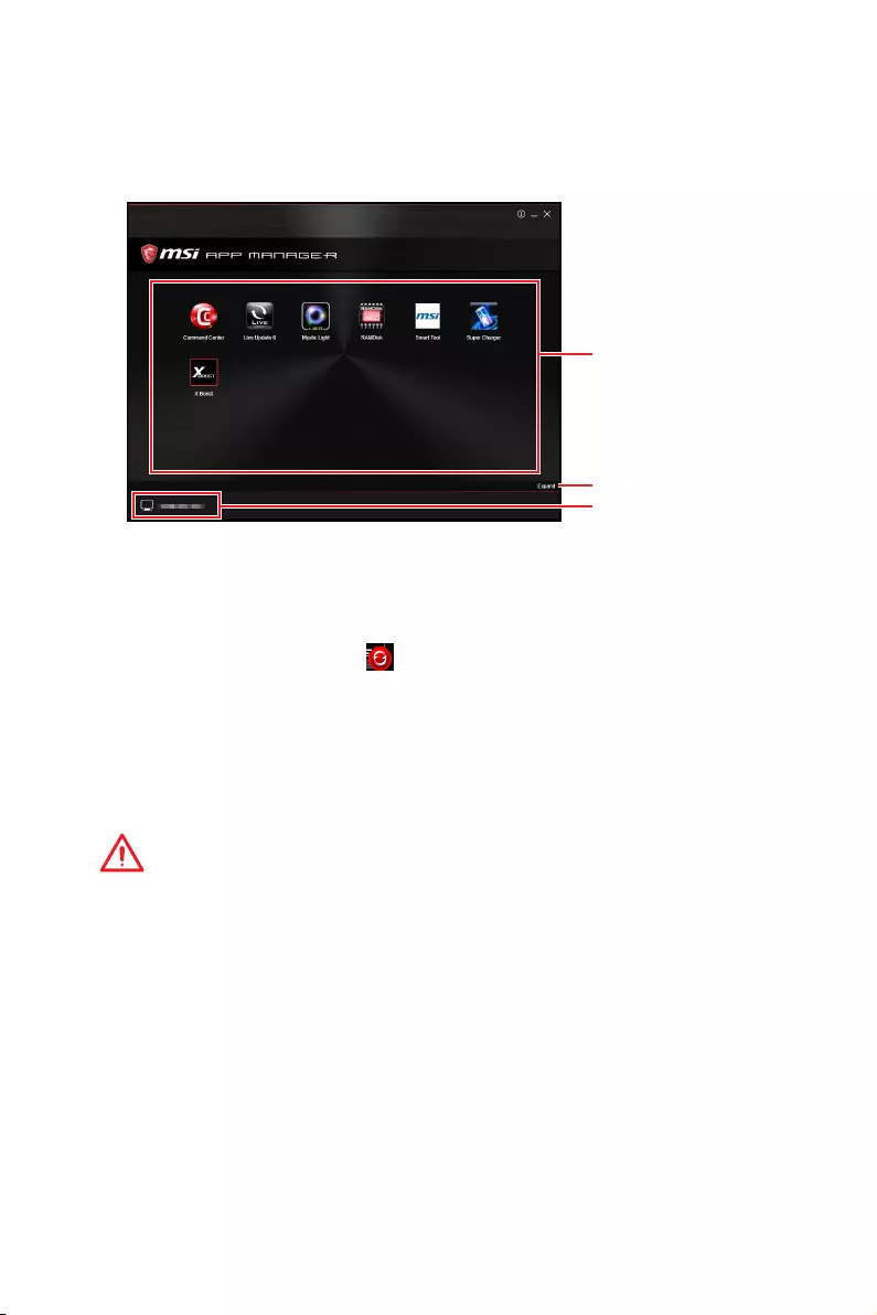
65
Software Description
APP MANAGER
APP MANAGER is a handy management application for integration of MSI applications
and software interface. Providing easy shortcut entrance and real-time update
information of all the MSI software and applications.
APP list
Total Install/ Update
Motherboard
Information
yAPP list — shows all the applications and software be supported by this motherboard.
An icon represents a entrance to the application.
Colorful icon — a colorful icon means that the application had have been
installed successfully and it is available. Double click on desired icon to access
the application. A refresh icon shows to inform you that the application has a
update version.
Gray icon — the icon with gray painting means that the application is not available
and you have to install it if necessary. Double click on the gray icon and the update
information will show. Click on the INSTALL button to install the application.
yMotherboard Information — shows the model name of motherboard.
yTotal Install/ Update — click on this tab to update/ install all the applications.
Important
Please note that, once you uninstall the APP MANAGER, all the MSI applications and
software will be uninstalled simultaneously.
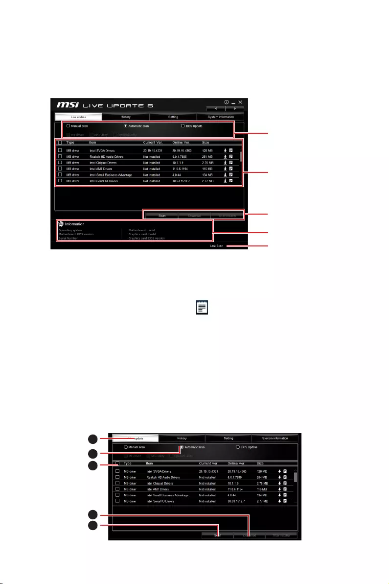
66 Software Description
LIVE UPDATE 6
LIVE UPDATE 6 is an application for the MSI® system to scan and download the latest
drivers, BIOS and utilities. With LIVE UPDATE 6, you don’t need to search the drivers
on websites, and don’t need to know the models of motherboard and graphics cards.
LIVE UPDATE 6 will download the appropriate drivers automatically.
Download Options
Download List
Scan / Download / Total
Installer button
System Information
Last Scanned Date
There are Live Update, History, Setting and System Information tabs at the top. You
can click the tab to switch the control panel.
yLive Update — When you launch LIVE UPDATE 6, you will see the Live update tab at
first. This tab allows you to select files to download. You can also read the relevant
information by clicking the information icon on the right of the item listed.
yHistory — shows the downloading history.
ySetting — allows you to specify the frequency that LIVE UPDATE 6 remind you to
update.
ySystem Information — displays the information of the system.
yFAQ — shows Frequently Asked Questions.
yOnline Help — shows Online Help information.
Updating The System
This section describes how to update your system with LIVE UPDATE 6. Please follow
the steps below:
1
2
4
5
3
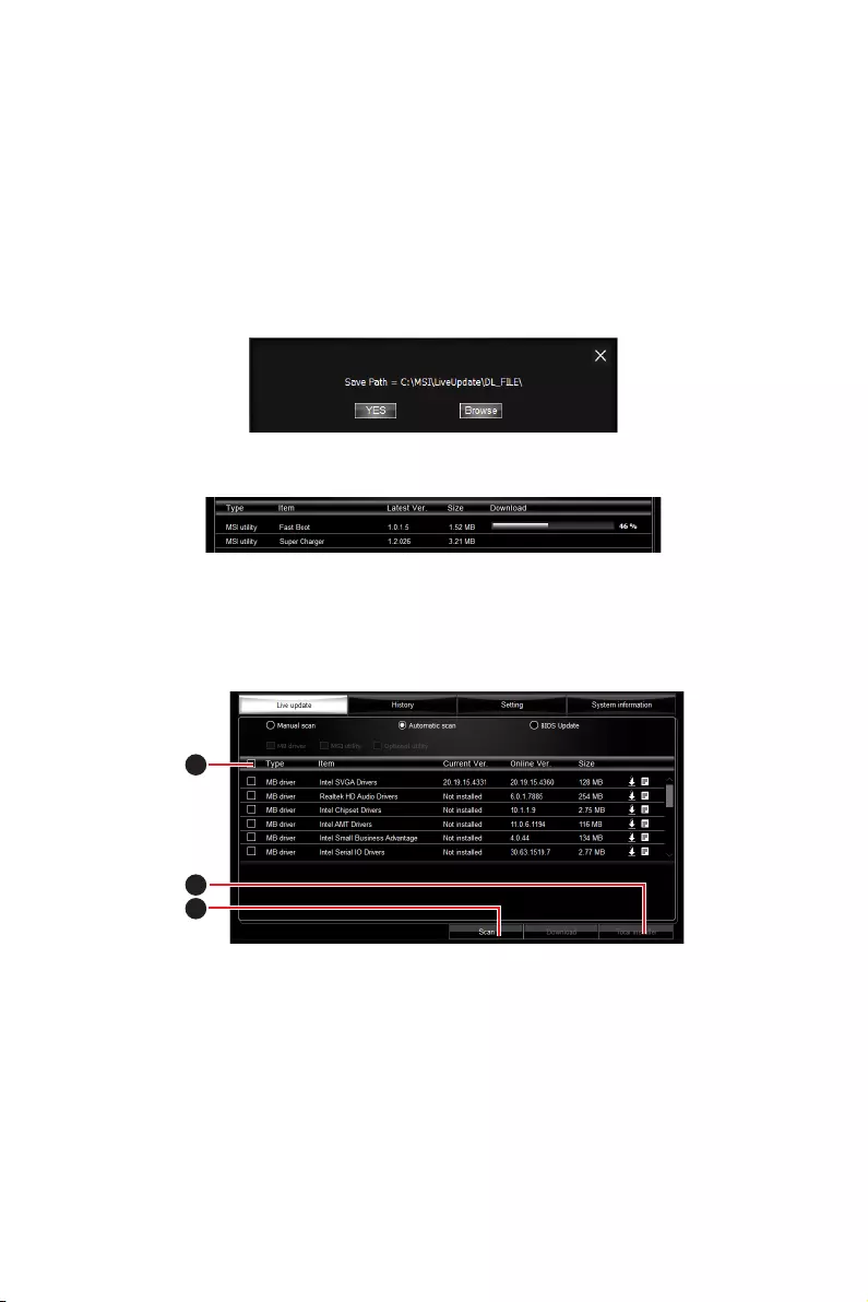
67
Software Description
1. Select the Live Update tab.
2. Choose Automatic scan, system will automatically scan all the items and search
for the latest update files. Or you can choose Manual scan and select the items you
wish to scan.
3. Click the Scan button at the bottom. It may take several moments to complete the
process.
4. When the download list appears, please select the items you intend to update.
5. Click Download button at the bottom.
6. When Save Path prompt, you can specify a download directory.
7. When downloading you will see the screen below. It may take several moments to
complete the process.
8. To install the applications, simply unpack the packages and install.
Total Installer
Total Installer is a convenient feature to simplify frequent installing procedure. To use
Total Installer:
1
2
3
1. Scan updates in Live Update tab.
2. Check the Select All check-box you intend to update.
3. Click the Total Installer button. LIVE UPDATE 6 will automatically install them.
4. When prompted, click OK to complete the Total Installer procedure
5. Reboot your system.
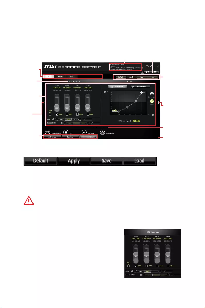
68 Software Description
COMMAND CENTER
COMMAND CENTER is an user-friendly software and exclusively developed by MSI,
helping users to adjust system settings and monitor status under OS. With the help
of COMMAND CENTER, making it possible to achieve easier and efficient monitoring
process and adjustments than that under BIOS. In addition, the COMMAND CENTER
can be a server for mobile remote control application.
Feature Menu
CPU TemperatureSystem Information
Feature Title
Feature
Control Panel
Previous
Feature
Next Feature
Profile
Buttons
Option Buttons
Page Indicator
Resize Corner
Profile Buttons
yDefault — load the default values for the current feature.
yApply — apply your changes.
ySave — store values in the file with individual file extension.
yLoad — load the values from the file.
Important
Every time you shut down the system, the configured setting will be restored to the
factory default. If you want to use the saved settings, you have to load it every time by
clicking the Load and Apply buttons.
CPU Frequency
CPU Frequency control panel allows you to change
CPU Ratio and Base clock. You can see the current
frequency of each CPU core on the top of the panel.
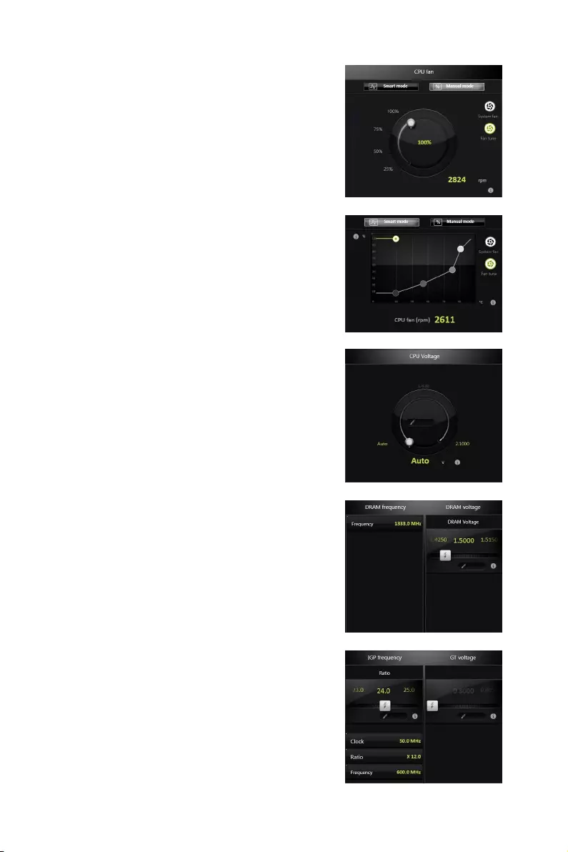
69
Software Description
CPU Fan
CPU Fan control panel provides Smart mode and
Manual Mode. You can switch the control mode by
clicking the Smart Mode and Manual Mode buttons
on the top of the CPU Fan control panel.
yManual Mode — allows you to manually control the
CPU fan speed by percentage.
ySmart Mode — a linear fan speed control feature.
The control panel contains 4 dots allows you to
drag and adjust the Smart Speed slopes. The fan
speed will be changed along these lines with CPU
temperature. The white dot will create strip chart in
real time.
ySystem Fan Button — to open the system fan control
panel in new window.
yFan Tune Button — to automatically optimize the
smart fan setting.
Manual Mode
Smart Mode
IGP Frequency & GT Voltage
yIGP Frequency — Allows you to adjust the IGP ratio,
and shows the IGP clock, ratio and frequency.
yGT Voltage — Allows you to adjust the GT voltage.
The risky values are displayed in red.
DRAM Frequency & DRAM Voltage
yDRAM Frequency — Shows the DRAM clock, ratio
and frequency.
yDRAM Voltage — Allows you to adjust the DRAM
voltage. The risky values are displayed in red.
CPU Voltage
CPU Voltage control panel allows you to control the
CPU voltage.
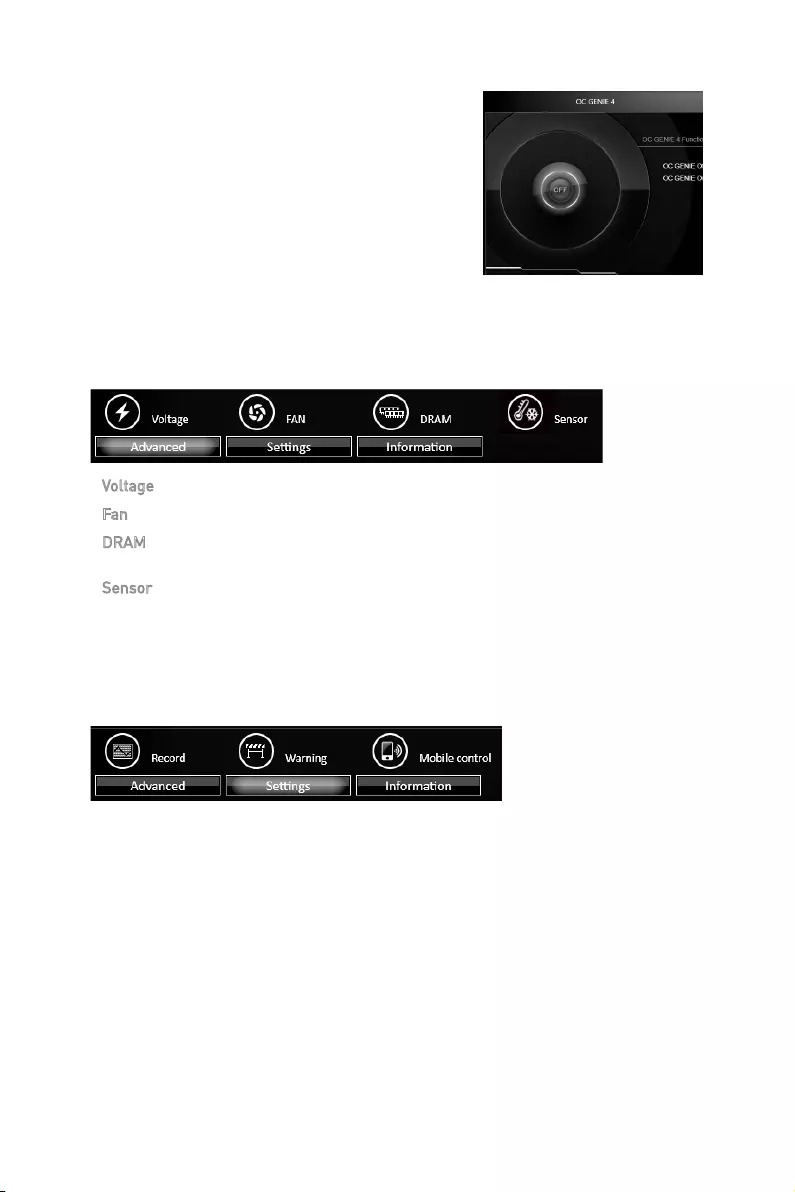
70 Software Description
Option Buttons — Advanced
When click the Advanced button, The Voltage, Fan and DRAM icons will appear.
yVoltage — allows you to adjust advanced voltage values of CPU and chipset.
yFan — allows you to control the system fans speed.
yDRAM — shows the current Advanced DRAM parameters, and allows you to change
the settings by selecting values from the drop-down menu on the right hand side.
ySensor — allows you to monitor your motherboard temperature and fan speed with
the virtual thermal image. You can drag and drop the fan icons to new locations. When
you press the Cooling button, all fans will run at full speed.
Option Buttons — Setting
When click the Setting button, The Record, Warning and Mobile Control icons will
appear.
yRecord — allows you to monitor the status of voltage, fan speed and temperature in
real time.
To filter record charts, select the check box next to the items.
When click the Play button, the chart pane will start to show the recording chart.
If you want to check the value of a specific spot on chart, please move the orange
vertical line to the spot.
History Record stores the data and names with date and time.
To make a history record: Select items and click the Record button. When
finished, click the Record button again. The data will be stored in the drop-down
menu.
To load a record, click the drop-down menu and select one from the list.
To delete a record, select the record that you want to delete, and click the Trash
Can icon.
OC GENIE 4
OC GENIE 4 provides a specified CPU frequency for
overclocking the CPU.
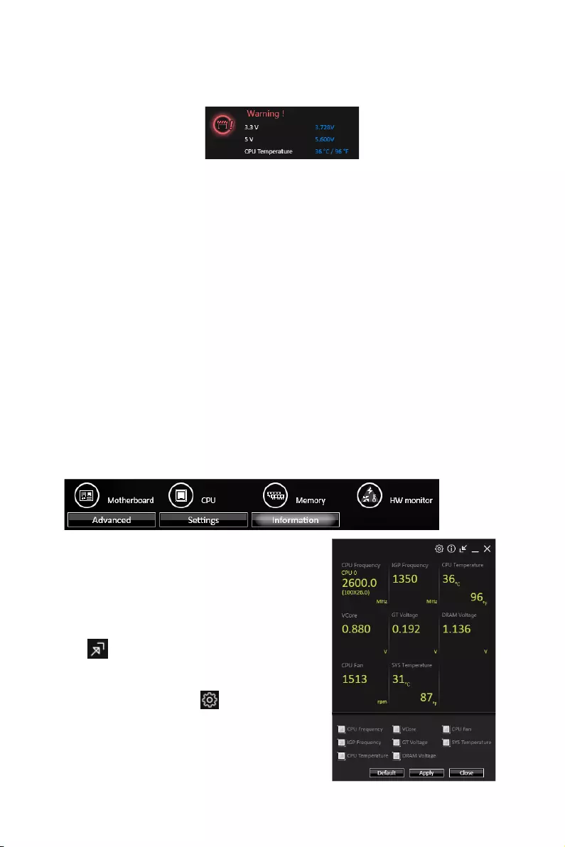
71
Software Description
yWarning — contains fields of voltage, fan speed and temperature for you to set the
threshold values. When system detects the status over your settings, a warning
message will pop-up.
yMobile Control — is only available for the motherboard with the built-in WiFi module.
It allows you to enable/disable the COMMAND CENTER Remote Server. Please refer to
the instruction on the Mobile Control control panel.
yTo start remote control: (optional)
1. Download and install MSI® COMMAND CENTER APP to your mobile device.
2. Enable COMMAND CENTER Remote Server on the Mobile Control panel.
3. Enable SoftAP Management.
4. Enter SSID and Password, and then click the Apply button.
5. Activate Wi-Fi® on your mobile device and connect to SoftAP with the SSID.
6. Run MSI® COMMAND CENTER APP on your mobile device.
7. Find the IP address on the SoftAP Management Setting area, and enter the IP
address on your MSI® COMMAND CENTER APP to link your system.
8. Press Refresh on the MSI® COMMAND CENTER APP to verify that monitoring and
OC functions are working properly.
Option Buttons — Information
When click the Information button, The Motherboard, CPU, Memory and HW monitor
icons will appear.
You can click the icons to open the related
information.
Gadget Mode
COMMAND CENTER provides a gadget mode to
monitor the system status. You can switch between
gadget mode and full mode by clicking the arrow
icon on the top left.
yTo arrange gadgets:
1. Click the Spanner icon on the Gadget
mode, a configuration panel will slide out.
2. Select the check box next to the items.
3. Click the Close button.
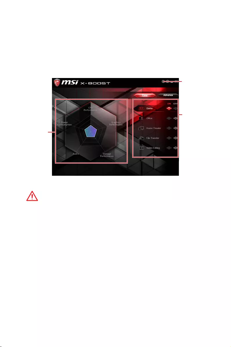
72 Software Description
yPerformance information — displays the system performance diagram of enabled
mode.
ySetting — enables or disables Run X-BOOST when windows starts.
X-BOOST
The MSI X-BOOST allows you to select the system performance mode to meet your
current system environment or support faster storage access speed for your external
storage or memory cards.
Easy
In Easy page, you can select one system performance mode to meet the current
system environment.
Setting
Performance
information
Performance
mode
yPerformance mode — moves over the mouse to any one of performance mode and
click on the ON button to enable it.
Important
The Customize mode is the default of system performance.
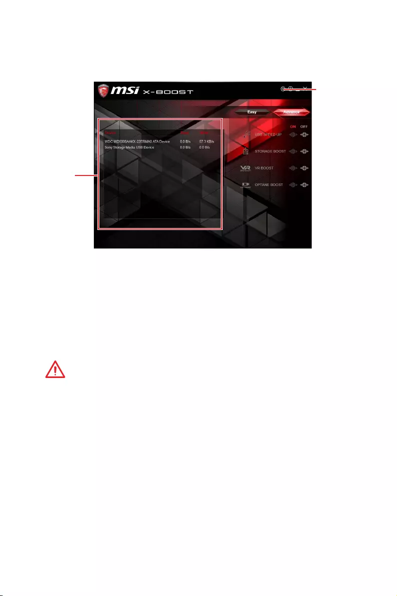
73
Software Description
Advance
In Advance page, you can enable the USB SPEED UP, the STORAGE BOOST and VR
BOOST.
Setting
Device
information
yDevice information — displays the information and current transfer rates/ access
speeds of USB/ storage devices.
ySetting — enables or disables Run X-BOOST when windows starts.
yUSB SPEED UP — supports faster data transfer rates of the USB storage devices.
ySTORAGE BOOST — supports faster access speed of storage device.
yVR BOOST — provides the optimized settings to boost the system for better VR
experience.
yOPTANE BOOST — supports faster access speed of Intel Optane memory (require a
reboot).
Important
y
Please note that you can only select one mode at a time from Easy or Advance page
as MSI X-BOOST function.
y
The improved transfer rate/ access speed will vary with the USB/ storage device.
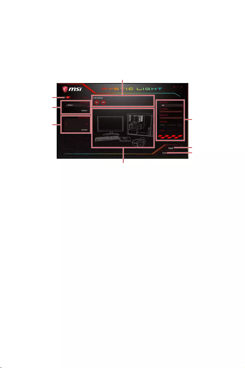
74 Software Description
MYSTICLIGHT
MYSTICLIGHT is an application allows you to control LED lights of MSI products.
Main Screen
The Main screen is used to configure what devices need to be synchronized and LED
light effect options.
Light Effect
Options
ON/ OFF All LED
Sync Profile
Device Setting
Sync Devices
Live Preview
Apply Button
Save Button
yON/OFF All LED — allows you to turn ON/ OFF all LED lights of sync devices.
ySync Devices — allows you to select devices to sync by clicking the device’s icon on
the Sync Device bar. The lighting effect of the sync devices will be controlled by the
main screen.
yLive Preview — gives you the full experience of your configuration’s look, feel while
you are editing it.
yLight Effect Options — allow you to customize lighting effect of the sync devices.
yApply Button — applies lighting effect settings.
ySync Profile — manages sets of sync device lighting effect settings.
All Sync — all devices are synchronized to the main lighting effect settings.
Individual — all devices lighting effects are applied to their respective settings.
Profile01~03 — selected sync devices lighting effects are synchronized to the main
lighting effect settings.
ySave Button — saves sync device settings and lighting effect settings to the current
Sync Profile.
yDevice Setting — switches to the other supported products.

75
Software Description
Motherboard Screen
The motherboard screen is used to configure the LED light effect of the motherboard.
Light Effect
Options
Motherboard
Name
Profile
Return Button
LED Area
Sync All
Live Preview
Apply Button
Save Button
yReturn Button — returns to the main screen.
yON/OFF All LED — allows you to turn ON/ OFF all LED lights of the motherboard.
ySync All — allows you to synchronize all LED light effect of the motherboard.
yMotherboard Name — shows the name of the motherboard.
yLive Preview — gives you the full experience of your configuration’s look, feel while
you are editing it.
yLight Effect Options — allow you to customize lighting effect of the sync devices.
yApply Button — applies lighting effect settings.
yProfile — manages sets of motherboard LED light effect settings.
ySave Button — saves sync device settings and lighting effect settings to the current
profile.
yLED Area — switches to the other LED area on the motherboard.
ON/ OFF All LED
Note: The motherboard picture and name may vary according to different models.
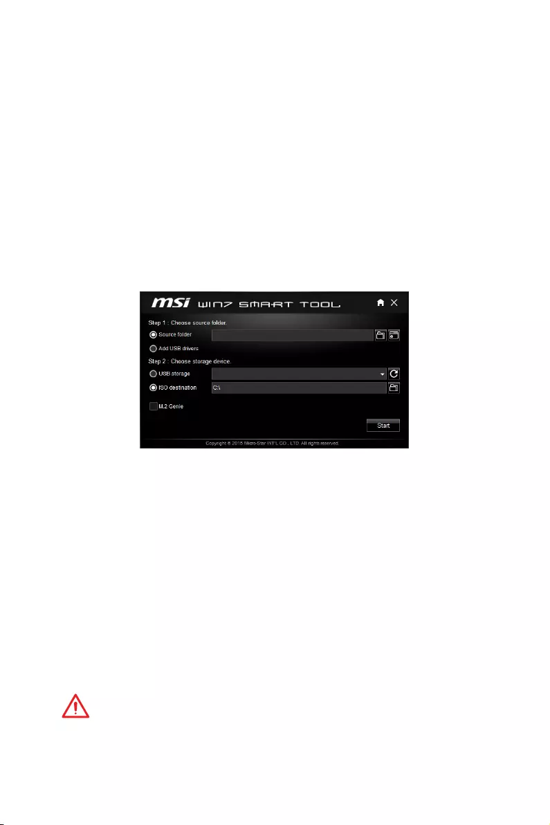
76 Software Description
MSI SMART TOOL
MSI SMART TOOL is a convenient tool that can help you to create your Windows
installation USB flash drive with USB 3.0 drivers, and it can also create a software
RAID.
Main menu
After installing and activating MSI SMART TOOL, it will display a main menu for you
to choose Win7 Smart Tool or Software RAID. Note that the Software RAID is only
available when your system equipped with at least 3 hard-disk drives (1 system disk
and 2 data disks).
WIN7 SMART TOOL
Before you can create your Windows installation USB flash drive, you’ll need to have
your Windows Installation DVD or ISO file, and also have a minimum of a 8GB USB
flash drive to create your installer. Be sure to backup files on the USB drive, this
process will erase it.
To create the Windows installation USB drive:
Step1. Choose source folder
yIn the Source folder box, type the name and path of your Windows ISO file, or
click Browse button and select the file from the dialog box. (This option will copy all
Windows installation files and USB 3.0 drivers)
yIf you already have the Windows Installation USB flash drive and just want to add
USB 3.0 drivers on it, you can choose Add USB drivers.
Step2. Choose Storage device
yChoose USB storage and select your USB flash drive in the drop-down list. In case
the USB flash drive is not listed, click the Refresh Drive button.
yIf you want to install Windows on the PCIe M.2 RAID that was created by BIOS > M.2
Genie (please refer to BIOS Setup Section for details), check the M.2 Genie checkbox
to copy iRST drivers to the USB flash drive.
yClick Start.
Important
You can also create an installer ISO image file by selecting the ISO destination in
Step2, and then burn it onto the DVD. However, this method does not support M.2
Genie.
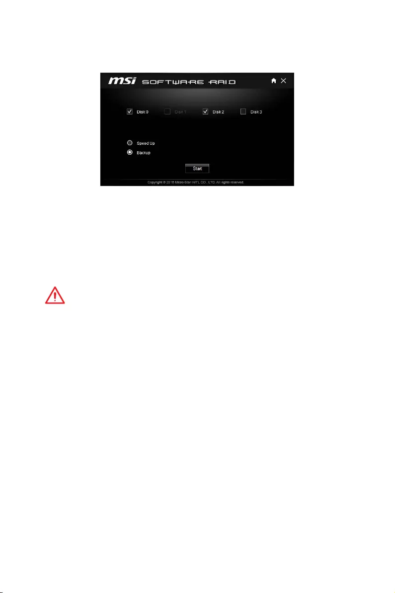
77
Software Description
SOFTWARE RAID
This utility allows you to create a software RAID in Windows system.
To create a software RAID:
1. Use checkboxs to select the disks you want included in your RAID.
2. Choose Speed Up or Backup for RAID type.
ySpeed Up = RAID0
yBackup = RAID1
3. Click Start.
4. When prompt Finish!, click OK.
Important
Software RAID can’t includ the system disk.
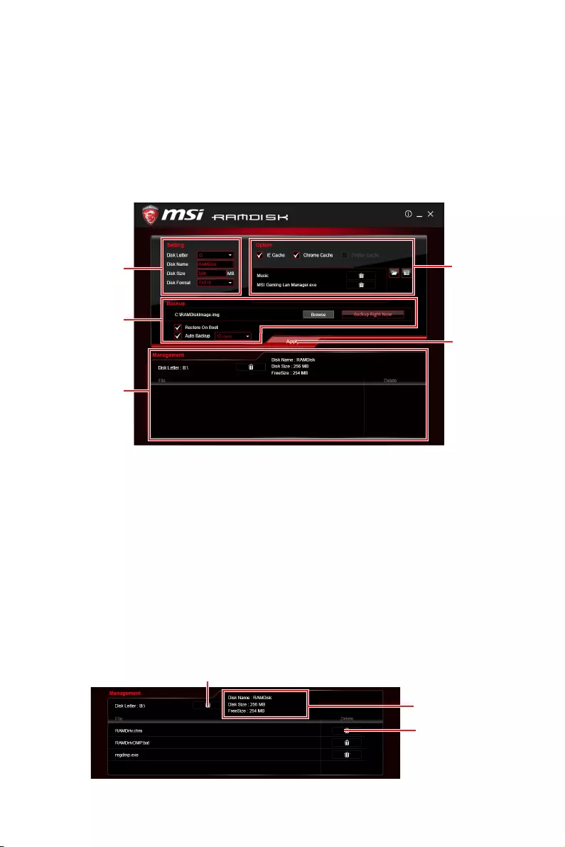
78 Software Description
RAMDISK
RAMDISK creates a virtual RAM drive using the available memory in your computer,
the performance of the RAMDISK is faster than an SSD and hard drive. RAMDISK
allows you to store any temporary information on it. Furthermore, using the RAMDISK
will extend your SSD’s life by sparing it from excessive reading and writing.
Creating a RAM Disk
When RAMDISK is started, it will create a default RAM disk. If you want to change
settings, refer to following instructions.
Backup
Management
Option
Apply
Button
ySetting — specify Letter, Name, Size and Format of the RAM disk.
yOption — select browser temporary files to save/load on the RAM disk. You can also
add software files to improve reading speed.
yBackup — specify backup and restore settings to prevent data loss. All files will be lost
each time the RAMDISK is stopped if you do not backup.
Browse Button — set the path to the image file.
Backup Right Now Button — manually backup files.
Restore On Boot — check this box to have the image file loaded automatically when
RAMDISK starts.
Auto Backup — check this box to backup automatically over a period of time.
yApply Button — allows you to apply changes.
yManagement — shows RAMDISK information and allows you to delete files.
Dislpay
information
Delete files
in the RAM
disk.
Remove the RAM disk
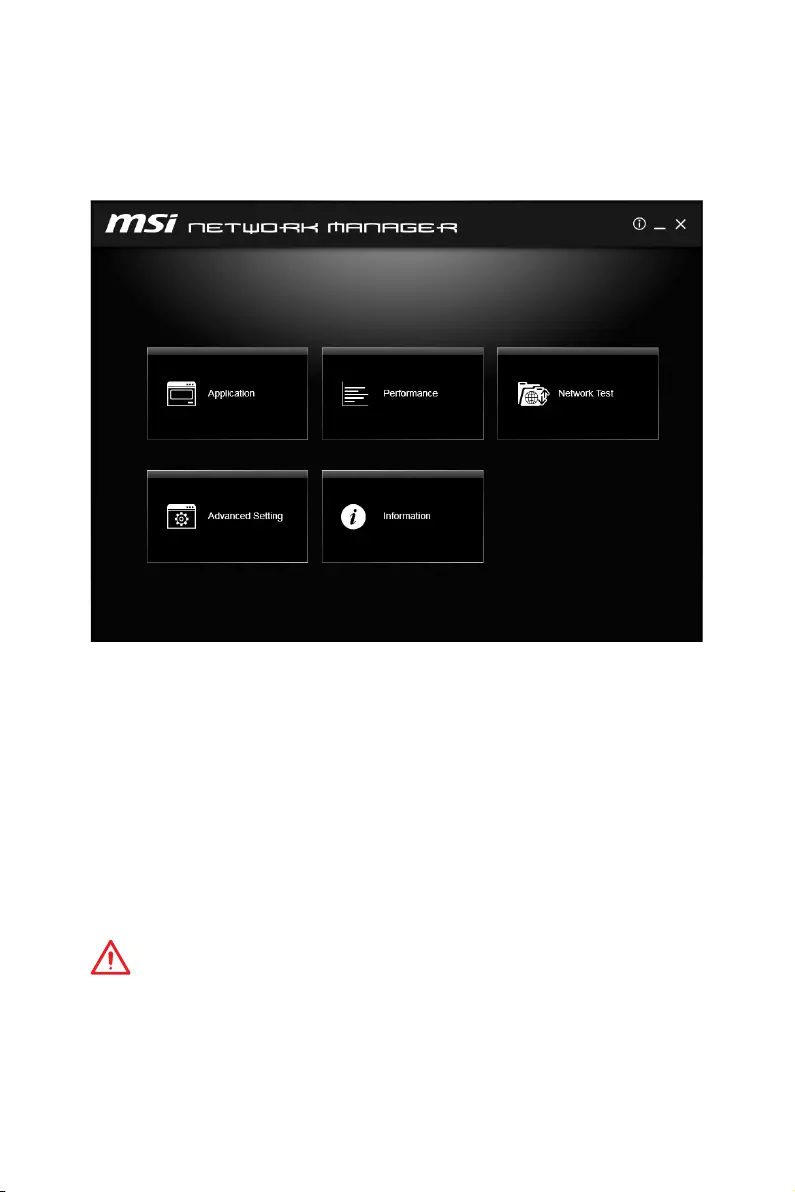
79
Software Description
NETWORK MANAGER
NETWORK MANAGER is an utility for traffic shaping for the Windows OS. It can keep
your internet fast during heavy upload/ download and improve your ping for online
games. If your motherboard has a Wi-Fi module, NETWORK MANAGER provides virtual
access point function for traffic shaping for your mobile devices.
yApplications — displays currently using network bandwidth applications. You can
prioritize Games, Medias or File sharing programs as high as possible.
yPerformance — shows top 5 applications by total traffic, allows you to monitor
network bandwidth usage.
yNetwork Test — allows you to setup bandwidth control.
yAdvanced Setting — allows you to expand RWIN to accelerate download speed. You
can also block IP address and setup virtual access point.
yInformation — shows version information.
Configuring Bandwidth
This section describes how to configure Internet Provider Speed. You can configure
default internet upload and download bandwidth from the Network Test tab on the
NETWORK MANAGER window.
Important
Before using the NETWORK MANAGER for the first time, you should use the Test
Network Speed button which runs a speed test of your current total Internet
bandwidth delivered through your Internet service provider.
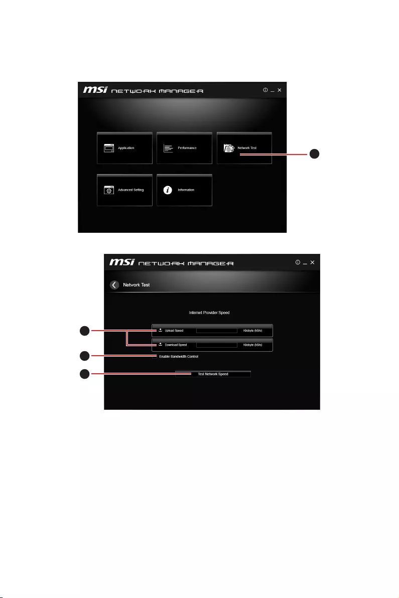
80 Software Description
Speed Testing
The speed testing is used to optimize bandwidth usage. To test the Upload and Down-
load speed, please follow the steps below:
1
1. Click the Network Test block in NETWORK MANAGER.
2
3
4
2. Click Test Network Speed button. The test takes several minutes to test your
network speed.
3. Enter the testing results into Upload Speed and Download Speed fields.
4. Check the Enable Bandwidth Control to allow the NETWORK MANAGER to
manage the bandwidth.
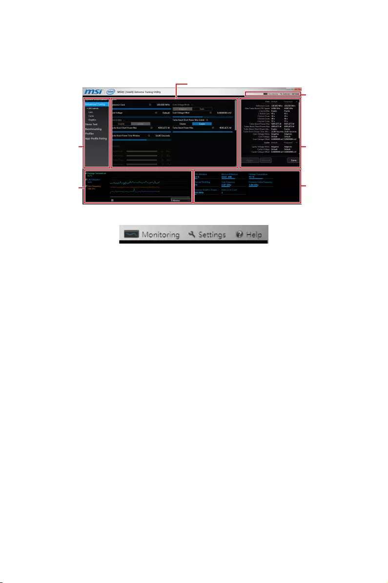
81
Software Description
Intel® Extreme Tuning Utility
Intel® Extreme Tuning Utility (Intel XTU) is a simple overclocking software for you to
tune, test and monitor your system.
Navigation
Views
Settings
Help
System
Table
System
Monitors
System
Graphs
Tuning Controls
yViews Settings Help
Views — toggles to switche between Monitoring and Show All view.
Settings — opens the General Settings window.
Help — displays the help content for Intel XTU in a separate window.
yNavigation — lists all of the major functions of Intel XTU.
System Information — shows the details about your system.
App-Profile Pairing — tunes automatically based on active application.
Manual Tuning — changes system settings in a free form.
Stress Test — tests the stability of your system.
Benchmarking — analyzes and compares your system’s performance against
other system profiles.
Profiles — manages sets of system settings.
yTuning Controls — displays the controls for changing the system settings in manual
tuning. For stress tests and profiles, this area displays the settings for these features.
ySystem Table — displays information about the current system settings and a
summary of your changes.
ySystem Graphs — shows measured system values over a period of time. The system
graphs update live as changes are detected in the system. You can customize the
system graphs to show the data you need for your overclocking strategy in the system
graphs preferences.
ySystem Monitors — shows the range of the value, averages, and the current value.
The monitors change color if the monitored values fall into warning or critical zones.
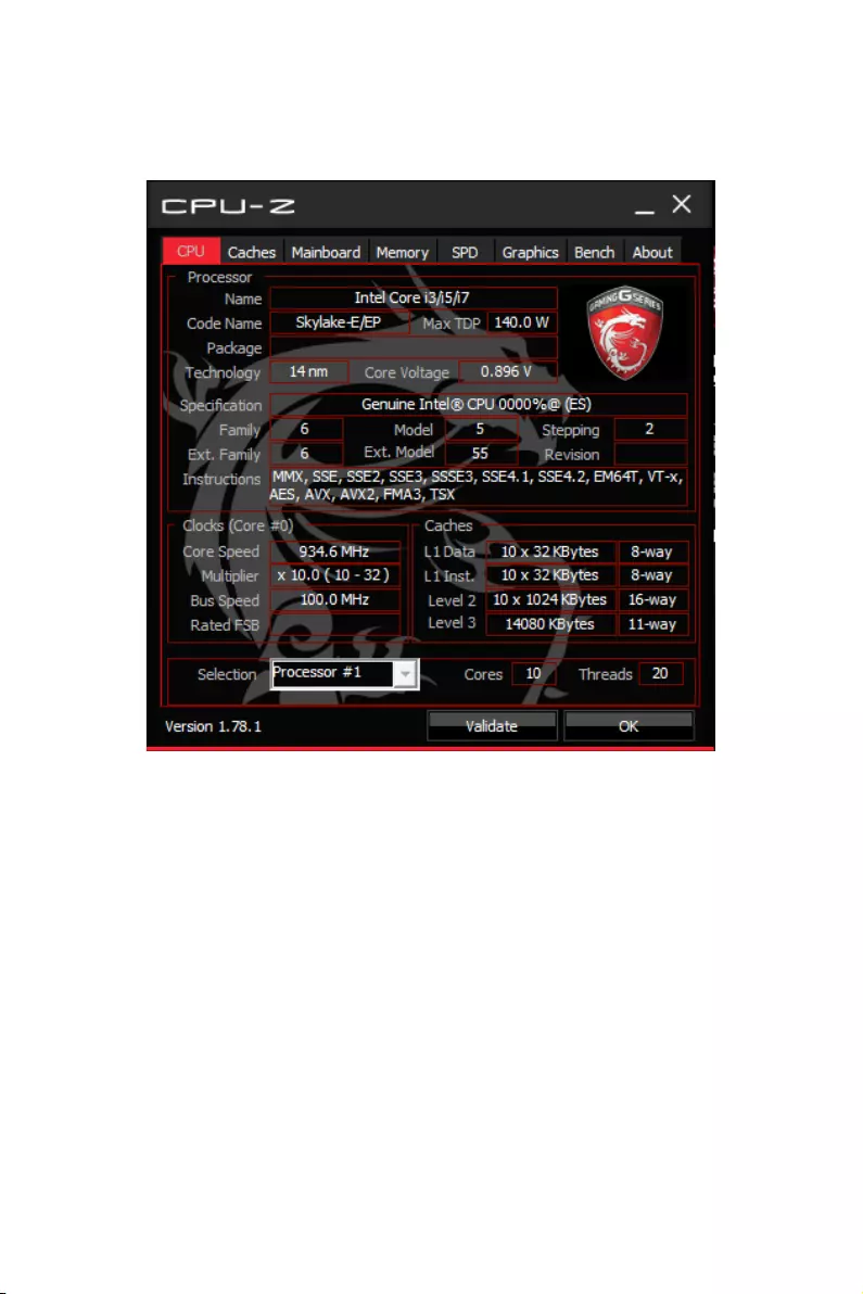
82 Software Description
CPU-Z
CPU-Z is an utility that gathers information on some of the main devices of your
system.
yCPU Tab — shows processor name, code name, package, specification, instructions
sets, core speed and cache levels.
yCaches Tab — shows extended information related to the cache capabilities.
yMainboard Tab — shows motherboard manufacturer, model name, chipset, BIOS
version and graphic interface.
yMemory Tab — shows memory type, memory size, channels, memory frequency.
ySPD Tab — shows specifications relating to each memory module connected to the
motherboard, including the size, type and frequency.
yGraphics Tab — shows GPU name, code name, core speed, memory size, and memory
type.
yBench Tab — allows you to run either a benchmark or a stress test on your processor.
yAbout Tab — shows the CPU-Z version, Windows version, DirectX version and allows
you to save the report file.
83
RAID Configuration
RAID Configuration
Below are the different types of a RAID.
RAID 0 breaks the data into blocks which are written to separate hard drives.
Spreading the hard drive I/O load across independent channels greatly
improves I/O performance.
RAID 1 provides data redundancy by mirroring data between the hard drives and
provides enhanced read performance.
RAID 5 provides data striping at the byte level and also stripe error correction
information. This results in excellent performance and good fault tolerance.
RAID 10 uses four hard drives to create a combination of RAID 0 and 1 by forming a
RAID 0 array from two RAID 1 arrays.
RAID level comparison
RAID 0 RAID 1 RAID 5 RAID 10
Minimum # drives 2 2 3 4
Data protection None Excellent Excellent Excellent
Read performance Excellent OK Good OK
Write performance Excellent Good OK Good
Capacity utilization 100% 50% 67%~(1-1/n) 50%
Using Intel® Rapid Storage Technology Option ROM
First, you need to set the SATA mode to RAID in BIOS to create, delete and reset RAID
volumes. To enter the IRST Option ROM, reboot and press Ctrl + I keys to enter the
IRST Option ROM during the POST, the following window will appear.
MAIN MENU
[ ]
DISK / VOLUME INFORMATION
[ ]
4. Recovery Volume Options
5. Acceleration Options
6. Exit
RAID Volumes :
None dened.
Physical Devices :
Port Device Model Serial # Size Type/Status (Vol ID)
1 XXXX-XXXXXXXX XXXXXXXXXXXXXX XXX.XGB Non-RAID Disk
2 XXXX-XXXXXXXX XXXXXXXXXXXXXX XXX.XGB Non-RAID Disk
[ ↑↓] — Select [ESC] — Exit [ENTER] — Select Menu
1. Create RAID Volume
2. Delete RAID Volume
3. Reset Disks to Non-RAID
[ ]
MAIN MENU
Important
The following procedure is only available with a newly-built system or if you are
reinstalling your OS. It should not be used to migrate an existing system to RAID.

84 RAID Configuration
Creating s RAID Volume
1. Select option Create RAID Volume and press Enter key. The following screen
appears.
[ ]
CREATE VOLUME MENU
[ ]
HELP
Name :
RAID 1 : Mirrors data (redundancy) .
[ ↑↓] — Change [TAB] — Next [ESC] — Previous Menu [ENTER] — Select
RAID Level :
Disks :
Strip Size :
Capacity :
Sync :
Volume0
RAID1(Mirror)
Select Disks
N / A
XXX.X GB
N / A
Create Volume
2. Specify a RAID Volume name and then press the Tab or Enter key to go to the next
field
3. Use the ↑↓←→ arrow keys to select the RAID level best suited to your usage
model in RAID Level.
4. In the Disk field, press Enter key and use Space key to select the disks you want to
create for the RAID volume, then click Enter key to finish selection. This field will
become available according to the selected RAID level.
5. Select the strip size for the RAID array by using the ↑ upper arrow or ↓ down
arrow keys to scroll through the available values, and pressing the Enter key
to select and advance to the next field. The available values range from 4KB to
128 KB in power of 2 increments. The strip size should be chosen based on the
planned drive usage. Here are some typical values:
RAID0 -128KB / RAID10 — 64KB / RAID5 — 64KB.
6. Select the capacity of the volume in the Capacity field. The default value is the
maximum volume capacity of the selected disks.
Important
Since you want to create two volumes, this default size (maximum) needs to be
reduced. Type in a new size for the first volume. As an example: if you want the first
volume to span the first half of the two disks, re-type the size to be half of what is
shown by default. The second volume, when created, will automatically span the
remainder of two hard drives.
7. Go to the Create Volume field and press Enter, a WARNING message will appear
for you to confirm if you are sure to create the RAID volume. Press Y to continue.
85
RAID Configuration
Removing a RAID Volume
Here you can delete the RAID volume, but please be noted that all data on RAID drives
will be lost.
Important
If your system currently boots to RAID and you delete the RAID volume in the IRST
Option ROM, your system will become unbootable.
Select option Delete RAID Volume from the main menu screen and press Enter key to
select a RAID volume for deletion. Then press Delete key to delete the selected RAID
volume. The following screen appears.
[ ]
DELETE VOLUME MENU
[ ]
HELP
Deleting a volume will reset the disks to non-RAID.
[ ↑↓] — Select [ESC] — Previous Menu [DEL] — Delete Volume
WARNING : ALL DISK DATA WILL BE DELETED.
(This does not apply to Recovery volumes)
Name Level Drives Capacity Status Bootable
Volume0 RAID1(Mirror) 2 XXX.XGB Normal Yes
ALL DATA IN THE VOLUME WILL BE LOST!
(This does not apply to Recovery volumes)
Are you sure you want to delete “Volume0”? (Y / N) :
DELETE VOLUME VERIFICATION
[ ]
Press Y key to accept the volume deletion.
Resetting Disks to Non-RAID
Select option Reset Disks to Non-RAID from the main menu screen and press Enter
to delete the RAID volume and remove any RAID structures from the drives. Use the
Space key to select the disks and press Enter key. A confirmation sentence will appear
below, and then press Y key to accept the selection
DISK / VOLUME INFORMATION
[ ]
4. Recovery Volume Options
4. Recovery Volume Options
5. Exit
RAID Volumes :
None dened.
Physical Devices :
Port Device Model Serial # Size Type/Status (Vol ID)
1 XXXX-XXXXXXXX XXXXXXXXXXXXXX XXX.XGB Non-RAID Disk
2 XXXX-XXXXXXXX XXXXXXXXXXXXXX XXX.XGB Non-RAID Disk
[ ↑↓] — Select [ESC] — Exit [ENTER] — Select Menu
1. Create RAID Volume
2. Delete RAID Volume
Resetting RAID disk will remove its RAID structures and revert it
to a non-RAID disk.
[ ]
RESET RAID DATA
WARNING : Resetting a disk causes all data on the disk to be lost.
(This does not apply to Recovery volumes)
Select the disks that should be reset.
[ ↑↓] — Previous/ Next [SPACE] — Selects [ENTER] — Selection Complete
Port Drive Model Serial # Size Status
1 XXXX-XXXXXXXX XXXXXXXXXXXXXX XXX.XGB Member Disk
2 XXXX-XXXXXXXX XXXXXXXXXXXXXX XXX.XGB Member Disk
[ ]
MAIN MENU

86 RAID Configuration
Important
y
You will lose all data on the RAID drives and any internal RAID structures when you
perform this operation.
y
Possible reasons to Reset Disks to Non-RAID could include issues such as
incompatible RAID configurations or a failed volume or failed disk.
Recovery Volume Options
Select option Recovery Volume Options from the main menu screen and press Enter
to change recovery volume mode. The following screen appears:
[ ]
RECOVERY VOLUME OPTIONS
[ ]
HELP
Enable Only Recovery Disk — enables recovery disk if available and
disables master disk.
Enable Only Master Disk — enables master disk if available and
disables recovery disk.
Actions will result in change from Continuous Update mode to On-Request.
[ ↑↓] — select [ESC] — Previous Menu [ENTER] — Select
1. Enable Only Recovery Disk
2. Enable Only Master Disk
Recovery mode will change from Continuous Update to On-Request after you enable
Only Recovery Disk or Only Master Disk.
Degraded RAID Array
A RAID 1, RAID 5 or RAID 10 volume is reported as degraded when one of its hard
drive members fails or is temporarily disconnected, and data mirroring is lost. As a
result, the system can only utilize the remaining functional hard drive member. To
re-establish data mirroring and restore data redundancy, refer to the procedure below
that corresponds to the current situation.
RAID Volumes
ID Name Level Strip Size Status Bootable
0 Volume0 RAID 1(Mirror) N/A XXX.XGB Degraded Yes
Physical Disks:
Port Device Model Serial # Size Type/Status(Vol ID)
1 XXXXXXXXXXXXX XXXXXXXXXXXXX XXX.XGB Member Disk (0)
2 XXXXXXXXXXXXX XXXXXXXXXXXXX XXX.XGB Member Disk (0)
Press <CTRL-I> to enter Conguration Utility..
Missing Hard Drive Member
1. Power off.
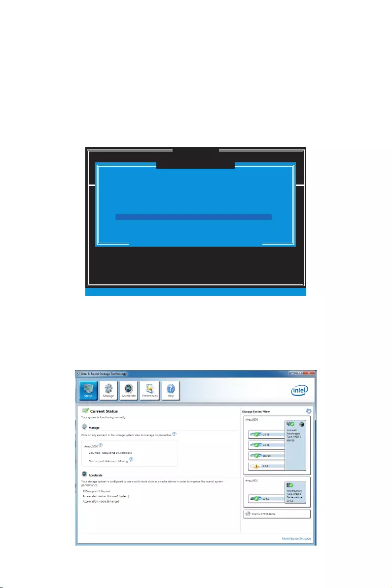
87
RAID Configuration
2. Reconnect the hard drive.
3. Reboot to Windows®; the rebuild will occur automatically.
Failed Hard Drive Member
1. Power off.
2. Replace the failed hard drive with a new one that is of equal or greater capacity.
3. Reboot the system to IRST Option ROM by press Ctrl + I keys during the POST.
4. Select the port of the destination disk for rebuilding, and then press Enter.
DISK / VOLUME INFORMATION
[ ]
4. Recovery Volume Options
4. Recovery Volume Options
5. Exit
RAID Volumes :
None dened.
Physical Devices :
Port Device Model Serial # Size Type/Status (Vol ID)
1 XXXX-XXXXXXXX XXXXXXXXXXXXXX XXX.XGB Non-RAID Disk
2 XXXX-XXXXXXXX XXXXXXXXXXXXXX XXX.XGB Non-RAID Disk
[ ↑↓] — Select [ESC] — Exit [ENTER] — Select Menu
1. Create RAID Volume
2. Delete RAID Volume
“Degraded” volume and disk available for rebuilding detected. Selecting
a disk initiates a rebuild. Rebuild completes in the operating system.
[ ]
DEGRADED VOLUME DETECTED
Select the port of the destination disk for rebuilding (ESC to exit):
[ ↑↓] — Previous/ Next [ENTER] — Select [ESC] — Exit
Port Drive Model Serial # Size
1 XXXX-XXXXXXXX XXXXXXXXXXXXXX XXX.XGB
[ ]
MAIN MENU
5. Exit IRST Option ROM, reboot to Windows®.
6. When prompted to rebuild the RAID volume, click Yes.
7. The Intel® Rapid Storage Technology application will be launched. Right-click
the new hard drive and select Rebuild to this Disk. The Rebuild Wizard will be
launched which will guide you through the process of rebuilding to the new hard
drive.

88 RAID Configuration
M.2 PCIe SSD RAID
You can create a M.2 PCIe SSD RAID volume with M.2/Optane Genie or UEFI BIOS.
Important
y
Please note that you must install M.2 SSDs of the same model and type in the M.2
slots to create the RAID 0 volume.
y
During windows setup, the RAID driver may be required and you can find the RAID
driver in MSI Driver Disc.
y
You can use MSI SMART TOOL to build the Windows
®
7/ 8.1/ 10 installation drive that
includes RAID driver.
y
If your system currently boots to M.2 PCIe SSD RAID and you delete the RAID volume,
your system will become unbootable.
y
When you delete the M.2 PCIe SSD RAID volume, please be noted that all data on M.2
PCIe SSDs will be lost.
Creating a M.2 PCIe SSD RAID with M.2/Optane Genie
1. Access the BIOS setup.
2. Enable M.2/Optane Genie by clicking the M.2/Optane Genie item.
3. Click Ok in the dialog.
4. Press F10 to save configuration and exit.
Creating a M.2 PCIe SSD RAID with UEFI BIOS
1. Access the BIOS setup
2. Switch to Advanced Mode by pressing F7 key.
3. Go to Settings > Advanced > Windows OS Configuration.
4. Set Windows 10 WHQL Support to Enabled.
5. Go to Settings > Advanced > Integrated Peripherals.
Setting\Advanced\Integrated Peripherals
SATA Conguration
SATA Mode [RAID Mode]
M2_1 Pcie Storage Remapping [Enabled]
M2_2 Pcie Storage Remapping [Enabled]
6. Set SATA Mode to RAID Mode.
7. Set both M2_1 Pcie Storage Remapping and M2_2 Pcie Storage Remapping to
Enabled.
8. Press F10 to save and exit and then press the Enter key to select Yes.
9. Reboot the system and access the BIOS setup again.
10. Switch to Advanced Mode by pressing F7 key.
11. Go to Settings > Advanced > Intel(R) Rapid Storage Technology.

89
RAID Configuration
12. Select Create RAID Volume and press Enter key.
…\Intel(R) Rapid Storage Technology\
Create RAID Volume
Create RAID Volume
Name: Volume1
RAID Level: [RAID0(Stripe)]
Select Disks:
PCIe, XXXXX XXXXXXXX-XXXX, XXXGB [X]
PCIe, XXXXX XXXXXXXX-XXXX, XXXGB [X]
Strip Size: [XXKB]
Capacity (MB): XXXXXX
Create Volume
13. Enter in a volume name.
14. Select the RAID level.
15. Use Space key to select the both PCIe SSDs.
16. If creating RAID 0, select the Strip Size; it is recommended that it be left at the
default value.
17. Go to the Create Volume field and press Enter.

90 RAID Configuration
Removing a M.2 PCIe SSD RAID Volume with M.2/Optane Genie
1. Access the BIOS setup.
2. Disable M.2/Optane Genie by clicking M.2/Optane Genie item.
3. Click Ok in the dialog.
4. Press F10 to save configuration and exit.
Removing a M.2 PCIe SSD RAID Volume with UEFI BIOS
1. Access the BIOS setup.
2. Switch to Advanced Mode by pressing F7 key.
3. Go to Settings > Advanced > Intel(R) Rapid Storage Technology.
4. Select a RAID volume and press Enter key.
5. Go to the Delete field and press Enter. The following screen appears
…\RAID VOLUME INFO\
Delete
Delete
Delete the RAID volume?
ALL DATA ON VOLUME WILL BE LOST!
Yes
No
6. Go to the Yes field and press Enter key to accept the volume deletion.

91
Intel® Optane™ Memory Configuration
Intel® Optane™ Memory Configuration
Intel® Optane™ memory can accelerate the Windows 10 64bit operating system. This
section describes how to install and remove the Intel® Optane™ memory.
System Requirements
yIntel® Optane™ memory ready MSI® motherboards
ySupported 7th Gen, or later, Intel® Core™ — i Processor
ySystem BIOS that supports the Intel® Rapid Storage Technology (Intel® RST) 15.5 or
later driver
yOperating system: Windows 10 64 bit (UEFI mode).
yIntel® Optane™ Memory Module
Installing the Intel® Optane™ memory
1. Update BIOS (refer to the Updating BIOS section).
2. Install the Intel® Optane™ memory module.
Power off the system.
Refer to the Specifications for location to install your Intel® Optane™ memory
module.
Install the Intel® Optane™ memory module into the M.2 slot.
3. Enable M.2/Optane Genie
Power on and press Delete key to enter BIOS Setup menu.
Enable M.2/Optane Genie by clicking the M.2/Optane Genie item.
Click Ok in the dialog.
Press F10 to save configuration and exit.
4. Install the Intel® Rapid Storage Technology 15.5
Reboot to operating system.
Install the Intel® Rapid Storage Technology 15.5
Reboot System.
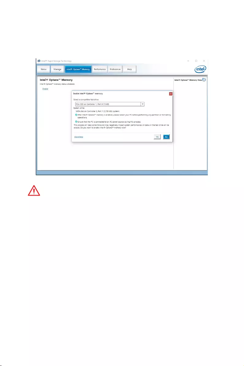
92 Intel® Optane™ Memory Configuration
5. Enable Intel® Optane™ Memory.
Enable Intel® Optane™ Memory via the Intel® Optane™ memory application
(auto-launches upon reboot).
Click Yes in the dialog.
Reboot System.
WARNING
Once you enable Intel
®
Optane™ memory, in order to prevent seriously damage your
operating system, please follow the cautions listed below.
y
DO NOT set the SATA mode back to AHCI in BIOS.
y
DO NOT revert back to older version of the BIOS.
y
DO NOT remove the Intel
®
Optane™ memory module.
y
DO NOT replace the CPU that is not supported by Intel
®
Optane™ Memory.
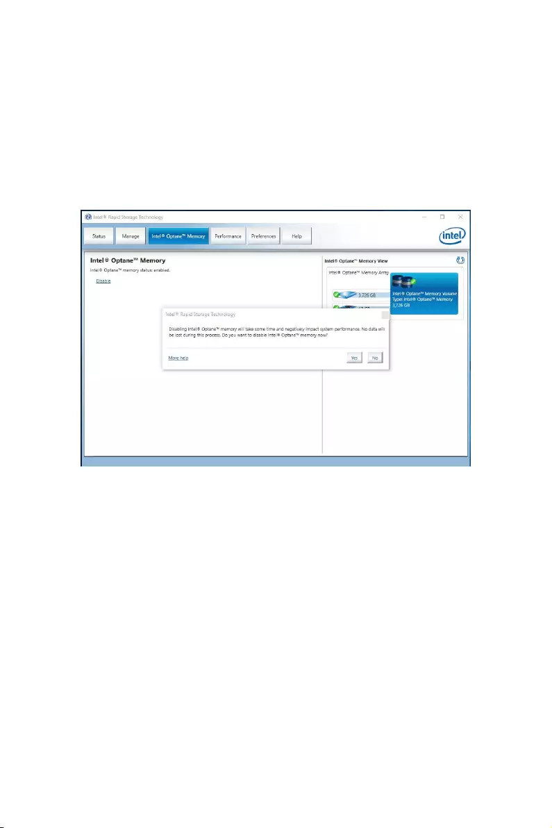
93
Intel® Optane™ Memory Configuration
Removing the Intel® Optane™ memory
If you no longer want to use Intel® Optane™ memory, you have to disable the Intel®
Optane™ memory before removing the Intel® Optane™ memory module to avoid
operating system damage. Please follow the steps below to remove the Intel® Optane™
memory.
1. Disable Intel® Optane™ Memory.
Disable Intel® Optane™ Memory via the Intel® Optane™ memory application
(Intel® Rapid Storage Technology).
Click Yes in the dialog.
Reboot System.
2. Disable M.2/Optane Genie
Press Delete key to enter BIOS Setup menu during POST.
Disable M.2/Optane Genie by clicking M.2/Optane Genie item.
Click Ok in the dialog.
Press F10 to save configuration and exit.
3. Remove the Intel® Optane™ memory module.
Power off the system.
Remove the Intel® Optane™ memory module.
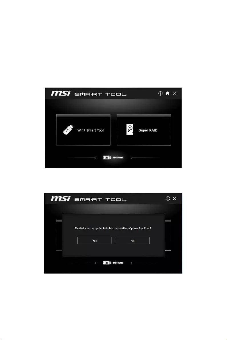
94 Intel® Optane™ Memory Configuration
Troubleshooting
When you installed the operating system in AHCI mode, the system will be changed to
RAID/ Optane mode after enabling Intel® Optane™ Memory. If you want to disable Intel
Optane Memory and switch BIOS setting from RAID/ Optane mode back to AHCI mode,
that may cause operating system damage. MSI has developed a software assistance
for this problem. You can disable Intel® Optane™ Memory and switch back to AHCI
mode while keep the system bootable with MSI SMART TOOL.
Please follow the steps below to disable Intel® Optane™ Memory and set the SATA
mode back to AHCI.
1. Run MSI SMART TOOL.
2. Click the OPTANE icon. (Note: the OPTANE icon is only available when Intel®
Optane™ Memory has been enabled)
3. Click Yes.
4. Reboot System.

95
Troubleshooting
Troubleshooting
Before sending the motherboard for RMA
repair, try to go over troubleshooting
guide first to see if your got similar
symptoms as mentioned below.
The power is not on.
yConnect the AC power cord to an
electrical outlet securely.
yCheck if all ATX power connectors
like ATX_PWR1, CPU_PWR1 are
connected from the power supply to the
motherboard?
ySome power supply units have a power
button on the rear side, make sure the
button is turned on.
yCheck if the power switch cable is
connected to JFP1 pin header properly.
yVerify the Clear CMOS jumper JBAT1 is
set to Keep DATA.
yTest with another known working power
supply of equal or greater wattage.
The power is on, but no signal to
monitor
yConnect the monitor power cord to a
electrical outlet securely.
yMake sure the monitor is turned on.
ySelect different inputs on the monitor.
yIf 3 long beeps are heard, remove all
memory modules and try to install only
one memory module in the DIMMA2 slot
first and then restart the computer.
yIf 1 long 2 short beeps are heard,
remove and reinstall the graphics card
and then restart the computer.
yTest with another known working
graphics card.
The computer does not boot after
updating the BIOS
yClear the CMOS.
yUse the secondary BIOS to bootup the
system (Only for motherboard with Dual
BIOS)
Lost BIOS password
yClear the CMOS, but that will cause
you to lose all customized settings in the
BIOS.
There is no audio
yAdjust the volume.
yConnect the speakers/headphones to
audio ports on the motherboard rear IO
panel.
yRemove secondary speakers/
headphones, HDMI cables, USB audio
devices.
yTest with another known working
speaker or headphone.
There is no network
yMake sure the network chipset driver
has been installed.
yVerify if the network cable is properly
connected and make sure the LAN port
LEDs are properly illuminated.
yVerify your TCP/IP settings.
yRestart or reset your router.
yTest with another known working LAN
cable.
The USB device is not working
yMake sure your USB drive driver has
been installed.
yVerify if USB device is listed in
Windows® Device Manager.
yConnect the USB device to other USB
port on the motherboard rear IO panel.
96 Regulatory Notices
FCC Compliance Statement
Note: This equipment has been tested and found to
comply with the limits for a Class B digital device,
pursuant to part 15 of the FCC Rules. These limits
are designed to provide reasonable protection against
harmful interference in a residential installation. This
equipment generates, uses and can radiate radio
frequency energy and, if not installed and used in
accordance with the instructions, may cause harmful
interference to radio communications. However, there
is no guarantee that interference will not occur in a
particular installation. If this equipment does cause
harmful interference to radio or television reception,
which can be determined by turning the equipment
off and on, the user is encouraged to try to correct the
interference by one or more of the following measures:
yReorient or relocate the receiving antenna.
yIncrease the separation between the equipment
and receiver.
yConnect the equipment into an outlet on a circuit
different from that to which the receiver is
connected.
yConsult the dealer or an experienced radio/TV
technician for help.
Caution: Changes or modifications not expressly
approved by the party responsible for compliance could
void the user’s authority to operate the equipment.
Tested to comply with FCC standards
FOR HOME OR OFFICE USE
This device complies with part 15 of the FCC Rules.
Operation is subject to the following two conditions:
(1) This device may not cause harmful interference, and
(2) this device must accept any interference received,
including interference that may cause undesired
operation.
CE Conformity
Products bearing the CE marking comply
with one or more of the following EU
Directives as may be applicable:
RED 2014/53/EU; Low Voltage Directive 2014/35/EU;
EMC Directive 2014/30/EU; RoHS Directive 2011/65/EU.
Compliance with these directives is assessed using
applicable European Harmonized Standards.
The point of contact for regulatory matters is MSI,
MSI-NL Eindhoven 5706 5692 ER Son.
B급 기기 (가정용 방송통신기자재)
이 기기는 가정용(B급) 전자파적합기기로서 주
로 가정에서 사용하는 것을 목적으로 하며, 모
든 지역에서 사용할 수 있습니다.
クラスB情報技術装置
この装置は、クラスB情報技術装置です。この
装置は、家庭環境で使用することを目的として
い ま す が、こ の 装 置 が ラ ジ オ や テ レ ビ ジ ョ ン 受
信機に近接して使用されると、受信障害を引き
起こすことがあります。取扱説明書に従って
正しい取り扱いをして下さい
VCCI-B
C-Tick Compliance
Battery Information
European Union:
Batteries, battery packs, and
accumulators should not be disposed of as
unsorted household waste. Please use the
public collection system to return, recycle,
or treat them in compliance with the local
regulations.
Taiwan:
廢電池請回收
For better environmental protection, waste
batteries should be collected separately
for recycling or special disposal.
California, USA:
The button cell battery may contain
perchlorate material and requires special
handling when recycled or disposed of in
California.
For further information please visit:
http://www.dtsc.ca.gov/hazardouswaste/perchlorate/
CAUTION: There is a risk of explosion, if battery is
incorrectly replaced.
Replace only with the same or equivalent type
recommended by the manufacturer.
Chemical Substances Information
In compliance with chemical substances regulations,
such as the EU REACH Regulation (Regulation EC
No. 1907/2006 of the European Parliament and the
Council), MSI provides the information of chemical
substances in products at:
http://www.msi.com/html/popup/csr/evmtprtt_pcm.
html
Regulatory Notices

97
Regulatory Notices
WEEE (Waste Electrical and
Electronic Equipment) Statement
ENGLISH
To protect the global environment and as
an environmentalist, MSI must remind
you that…
Under the European Union (“EU”)
Directive on Waste Electrical and
Electronic Equipment, Directive 2002/96/
EC, which takes effect on August 13,
2005, products of “electrical and electronic equipment”
cannot be discarded as municipal wastes anymore, and
manufacturers of covered electronic equipment will
be obligated to take back such products at the end of
their useful life. MSI will comply with the product take
back requirements at the end of life of MSI-branded
products that are sold into the EU. You can return these
products to local collection points.
DEUTSCH
Hinweis von MSI zur Erhaltung und Schutz unserer
Umwelt
Gemäß der Richtlinie 2002/96/EG über Elektro- und
Elektronik-Altgeräte dürfen Elektro- und Elektronik-
Altgeräte nicht mehr als kommunale Abfälle entsorgt
werden. MSI hat europaweit verschiedene Sammel-
und Recyclingunternehmen beauftragt, die in die
Europäische Union in Verkehr gebrachten Produkte,
am Ende seines Lebenszyklus zurückzunehmen.
Bitte entsorgen Sie dieses Produkt zum gegebenen
Zeitpunkt ausschliesslich an einer lokalen
Altgerätesammelstelle in Ihrer Nähe.
FRANÇAIS
En tant qu’écologiste et afin de protéger
l’environnement, MSI tient à rappeler ceci…
Au sujet de la directive européenne (EU) relative aux
déchets des équipement électriques et électroniques,
directive 2002/96/EC, prenant effet le 13 août 2005, que
les produits électriques et électroniques ne peuvent
être déposés dans les décharges ou tout simplement
mis à la poubelle. Les fabricants de ces équipements
seront obligés de récupérer certains produits en fin
de vie. MSI prendra en compte cette exigence relative
au retour des produits en fin de vie au sein de la
communauté européenne. Par conséquent vous pouvez
retourner localement ces matériels dans les points de
collecte.
РУССКИЙ
Компания MSI предпринимает активные действия
по защите окружающей среды, поэтому напоминаем
вам, что….
В соответствии с директивой Европейского
Союза (ЕС) по предотвращению загрязнения
окружающей среды использованным электрическим
и электронным оборудованием (директива
WEEE 2002/96/EC), вступающей в силу 13
августа 2005 года, изделия, относящиеся к
электрическому и электронному оборудованию,
не могут рассматриваться как бытовой мусор,
поэтому производители вышеперечисленного
электронного оборудования обязаны принимать
его для переработки по окончании срока службы.
MSI обязуется соблюдать требования по приему
продукции, проданной под маркой MSI на территории
EC, в переработку по окончании срока службы. Вы
можете вернуть эти изделия в специализированные
пункты приема.
ESPAÑOL
MSI como empresa comprometida con la protección
del medio ambiente, recomienda:
Bajo la directiva 2002/96/EC de la Unión Europea
en materia de desechos y/o equipos electrónicos,
con fecha de rigor desde el 13 de agosto de 2005,
los productos clasificados como “eléctricos y
equipos electrónicos” no pueden ser depositados
en los contenedores habituales de su municipio, los
fabricantes de equipos electrónicos, están obligados
a hacerse cargo de dichos productos al termino de
su período de vida. MSI estará comprometido con los
términos de recogida de sus productos vendidos en
la Unión Europea al final de su periodo de vida. Usted
debe depositar estos productos en el punto limpio
establecido por el ayuntamiento de su localidad o
entregar a una empresa autorizada para la recogida de
estos residuos.
NEDERLANDS
Om het milieu te beschermen, wil MSI u eraan
herinneren dat….
De richtlijn van de Europese Unie (EU) met betrekking
tot Vervuiling van Electrische en Electronische
producten (2002/96/EC), die op 13 Augustus 2005 in
zal gaan kunnen niet meer beschouwd worden als
vervuiling. Fabrikanten van dit soort producten worden
verplicht om producten retour te nemen aan het
eind van hun levenscyclus. MSI zal overeenkomstig
de richtlijn handelen voor de producten die de
merknaam MSI dragen en verkocht zijn in de EU. Deze
goederen kunnen geretourneerd worden op lokale
inzamelingspunten.
SRPSKI
Da bi zaštitili prirodnu sredinu, i kao preduzeće koje
vodi računa o okolini i prirodnoj sredini, MSI mora da
vas podesti da…
Po Direktivi Evropske unije (“EU”) o odbačenoj
ekektronskoj i električnoj opremi, Direktiva 2002/96/
EC, koja stupa na snagu od 13. Avgusta 2005, proizvodi
koji spadaju pod “elektronsku i električnu opremu”
ne mogu više biti odbačeni kao običan otpad i
proizvođači ove opreme biće prinuđeni da uzmu natrag
ove proizvode na kraju njihovog uobičajenog veka
trajanja. MSI će poštovati zahtev o preuzimanju ovakvih
proizvoda kojima je istekao vek trajanja, koji imaju MSI
oznaku i koji su prodati u EU. Ove proizvode možete
vratiti na lokalnim mestima za prikupljanje.
POLSKI
Aby chronić nasze środowisko naturalne oraz jako
firma dbająca o ekologię, MSI przypomina, że…
Zgodnie z Dyrektywą Unii Europejskiej (“UE”) dotyczącą
odpadów produktów elektrycznych i elektronicznych
(Dyrektywa 2002/96/EC), która wchodzi w życie 13
sierpnia 2005, tzw. “produkty oraz wyposażenie
elektryczne i elektroniczne “ nie mogą być traktowane
jako śmieci komunalne, tak więc producenci tych
produktów będą zobowiązani do odbierania ich w
momencie gdy produkt jest wycofywany z użycia.
MSI wypełni wymagania UE, przyjmując produkty
(sprzedawane na terenie Unii Europejskiej) wycofywane
z użycia. Produkty MSI będzie można zwracać w
wyznaczonych punktach zbiorczych.

98 Regulatory Notices
TÜRKÇE
Çevreci özelliğiyle bilinen MSI dünyada çevreyi
korumak için hatırlatır:
Avrupa Birliği (AB) Kararnamesi Elektrik ve Elektronik
Malzeme Atığı, 2002/96/EC Kararnamesi altında 13
Ağustos 2005 tarihinden itibaren geçerli olmak üzere,
elektrikli ve elektronik malzemeler diğer atıklar
gibi çöpe atılamayacak ve bu elektonik cihazların
üreticileri, cihazların kullanım süreleri bittikten sonra
ürünleri geri toplamakla yükümlü olacaktır. Avrupa
Birliği’ne satılan MSI markalı ürünlerin kullanım
süreleri bittiğinde MSI ürünlerin geri alınması isteği ile
işbirliği içerisinde olacaktır. Ürünlerinizi yerel toplama
noktalarına bırakabilirsiniz.
ČESKY
Záleží nám na ochraně životního prostředí — společnost
MSI upozorňuje…
Podle směrnice Evropské unie (“EU”) o likvidaci
elektrických a elektronických výrobků 2002/96/
EC platné od 13. srpna 2005 je zakázáno likvidovat
“elektrické a elektronické výrobky” v běžném
komunálním odpadu a výrobci elektronických
výrobků, na které se tato směrnice vztahuje, budou
povinni odebírat takové výrobky zpět po skončení
jejich životnosti. Společnost MSI splní požadavky na
odebírání výrobků značky MSI, prodávaných v zemích
EU, po skončení jejich životnosti. Tyto výrobky můžete
odevzdat v místních sběrnách.
MAGYAR
Annak érdekében, hogy környezetünket megvédjük,
illetve környezetvédőként fellépve az MSI emlékezteti
Önt, hogy …
Az Európai Unió („EU”) 2005. augusztus 13-án hatályba
lépő, az elektromos és elektronikus berendezések
hulladékairól szóló 2002/96/EK irányelve szerint
az elektromos és elektronikus berendezések
többé nem kezelhetőek lakossági hulladékként,
és az ilyen elektronikus berendezések gyártói
kötelessé válnak az ilyen termékek visszavételére
azok hasznos élettartama végén. Az MSI betartja a
termékvisszavétellel kapcsolatos követelményeket
az MSI márkanév alatt az EU-n belül értékesített
termékek esetében, azok élettartamának végén. Az
ilyen termékeket a legközelebbi gyűjtőhelyre viheti.
ITALIANO
Per proteggere l’ambiente, MSI, da sempre amica della
natura, ti ricorda che….
In base alla Direttiva dell’Unione Europea (EU) sullo
Smaltimento dei Materiali Elettrici ed Elettronici,
Direttiva 2002/96/EC in vigore dal 13 Agosto 2005,
prodotti appartenenti alla categoria dei Materiali
Elettrici ed Elettronici non possono più essere eliminati
come rifiuti municipali: i produttori di detti materiali
saranno obbligati a ritirare ogni prodotto alla fine
del suo ciclo di vita. MSI si adeguerà a tale Direttiva
ritirando tutti i prodotti marchiati MSI che sono stati
venduti all’interno dell’Unione Europea alla fine del
loro ciclo di vita. È possibile portare i prodotti nel più
vicino punto di raccolta
日本JIS C 0950材質宣言
日本工業規格JIS C 0950に よ り、2006年7月1日以降に販
売される特定分野の電気および電子機器について、製造
者による含有物質の表示が義務付けられます。
http://www.msi.com/html/popup/csr/cemm_jp.html
http://tw.msi.com/html/popup/csr_tw/cemm_jp.html
India RoHS
This product complies with the “India E-waste
(Management and Handling) Rule 2011” and
prohibits use of lead, mercury, hexavalent chromium,
polybrominated biphenyls or polybrominated diphenyl
ethers in concentrations exceeding 0.1 weight % and
0.01 weight % for cadmium, except for the exemptions
set in Schedule 2 of the Rule.
Türkiye EEE yönetmeli i
Türkiye Cumhuriyeti: EEE Yönetmeli ine Uygundur
Україна обмеження на
наявність небезпечних речовин
Обладнання відповідає вимогам Технічного
регламенту щодо обмеження використання
деяких небезпечних речовин в електричному та
електронному обладнані, затвердженого постановою
Кабінету Міністрів України від 3 грудня 2008 № 1057.
Việt Nam RoHS
Kể từ ngày 01/12/2012, tất cả các sản phẩm do công
ty MSI sản xuất tuân thủ Thông tư số 30/2011/TT-BCT
quy định tạm thời về giới hạn hàm lượng cho phép của
một số hóa chất độc hại có trong các sản phẩm điện,
điện tử”
Environmental Policy
yThe product has been designed to
enable proper reuse of parts and
recycling and should not be thrown
away at its end of life.
yUsers should contact the local
authorized point of collection for
recycling and disposing of their end-of-life products.
yVisit the MSI website and locate a nearby distributor
for further recycling information.
yUsers may also reach us at gpcontdev@msi.com for
information regarding proper Disposal, Take-back,
Recycling, and Disassembly of MSI products.
99
Regulatory Notices
Copyright
Micro-Star Int’l Co.,Ltd.
Copyright © 2017 All rights reserved.
The material in this document is the intellectual
property of Micro-Star Int’l Co.,Ltd. We take every care
in the preparation of this document, but no guarantee
is given as to the correctness of its contents. Our
products are under continual improvement and we
reserve the right to make changes without notice.
Technical Support
If a problem arises with your system and no solution
can be obtained from the user guide, please
contact your place of purchase or local distributor.
Alternatively, please try the following help resources
for further guidance.
yVisit the MSI website for technical guide, BIOS
updates, driver updates, and other information:
http://www.msi.com
yRegister your product at: http://register.msi.com
Trademark Recognition
All product names used in this manual are the
properties of their respective owners and are
acknowledged.
Revision History
Version 2.0, 2017/08, First release.
产品中有害物质的名称及含量
部件名称
有害物质
铅
(Pb)
汞
(Hg)
镉
(Cd)
六价铬
(Cr(VI))
多溴联苯
(PBB)
多溴二苯醚
(PBDE)
印刷电路板组件* X O O O O O
电池** X O O O O O
外部信号连接头 X O O O O O
线材 X O O O O O
本表格依据 SJ/T 11364 的规定编制。
O: 表示该有害物质在该部件所有均质材料中的含量均在 GB/T 26572 规定的限量要求以下。
X: 表示该有害物质至少在该部件的某一均质材料中的含量超出 GB/T 26572 规定的限量要求,但所有部件都符合欧盟
RoHS要 求。
* 印刷电路板组件: 包括印刷电路板及其构成的零部件。
** 电池本体上如有环保使用期限标识,以本体标识为主。
■ 上述有毒有害物质或元素清单会依型号之部件差异而有所增减。
■ 產品部件本体上如有环保使用期限标识,以本体标识为主。
限用物質含有情況標示聲明書
單元
限用物質及其化學符號
鉛
(Pb)
汞
(Hg)
鎘
(Cd)
六價鉻
(Cr+6)
多溴聯苯
(PBB)
多溴二苯醚
(PBDE)
電路板 OOOOOO
電子元件 – OOOOO
金屬機構件 – OOOOO
塑膠機構件 OOOOOO
備考1. » 超出0.1 wt % » 及 » 超出0.01 wt % » 係指限用物質之百分比含量超出百分比含量基準值。
備考2. » O » 係指該項限用物質之百分比含量未超出百分比含量基準值。
備考3. » – » 係指該項限用物質為排除項目。
User’s Guide
99 pages
en
User’s Guide
194 pages
User’s Guide
164 pages
MSI Z370 SLI Plus Specification
The MSI Z370 SLI Plus is a motherboard designed to support Intel’s 8th and 9th generation Core processors, utilizing the LGA 1151 socket. It is built on the Intel Z370 chipset, offering a solid foundation for high-performance computing and gaming. The motherboard supports dual-channel DDR4 memory, with a capacity of up to 64GB across four DIMM slots, and supports memory overclocking up to 4000 MHz, ensuring fast data processing and multitasking efficiency.
Equipped with multiple PCIe slots, the Z370 SLI Plus supports NVIDIA SLI and AMD CrossFire technologies, enabling multi-GPU configurations for enhanced graphics performance. It features two M.2 slots and six SATA 6Gb/s ports for flexible and fast storage solutions, catering to both SSD and HDD configurations. The motherboard also includes USB 3.1 Gen2 Type-A and Type-C ports for high-speed data transfer, along with additional USB 3.1 Gen1 and USB 2.0 connections for peripheral support.
The MSI Z370 SLI Plus boasts a robust power design with Military Class 5 components, ensuring stability and reliability under demanding conditions. Its advanced thermal solution includes extended heatsinks and fan headers with smart fan control, maintaining optimal temperatures during intensive tasks. The motherboard’s audio capabilities are powered by Audio Boost 4 with Nahimic 2+, offering immersive sound quality.
Networking is facilitated by an Intel Gigabit LAN controller, providing fast and reliable internet connectivity. The motherboard also features MSI’s Mystic Light, allowing users to customize RGB lighting to enhance their system’s aesthetic appeal. With its blend of performance, expandability, and reliability, the MSI Z370 SLI Plus is a versatile choice for enthusiasts and gamers seeking a feature-rich motherboard.
MSI Z370 SLI Plus F.A.Q.
To update the BIOS, visit the MSI official website and download the latest BIOS file. Extract the file to a USB drive, enter BIOS setup by pressing ‘Delete’ during startup, and use the M-Flash utility to update the BIOS.
The MSI Z370 SLI Plus supports up to 64GB of DDR4 RAM across four DIMM slots.
Ensure all cables are properly connected, check the RAM and GPU seating, reset the CMOS by removing the battery or using the jumper, and try booting with minimal hardware.
Yes, the MSI Z370 SLI Plus supports NVMe SSDs via its M.2 slots, offering high-speed data transfer rates.
Ensure the graphics card is properly seated, check the PCIe power connectors, update the motherboard BIOS, and test the card in another slot or system if possible.
Enter the BIOS setup by pressing ‘Delete’ at startup, navigate to the ‘OC’ tab, and enable the XMP profile to optimize RAM performance.
The MSI Z370 SLI Plus offers 6 SATA ports and 2 M.2 slots for a variety of storage configurations, supporting both SATA and PCIe/NVMe SSDs.
You can monitor system temperatures using MSI’s Command Center or BIOS hardware monitor, as well as third-party tools like HWMonitor.
To reset the CMOS, remove the power, locate the CMOS battery, remove it for a few minutes, or use the CLR_CMOS jumper, and then reattach the battery or jumper.
Use the BIOS or MSI’s Command Center software to adjust fan curves, ensuring optimal cooling and noise levels based on system temperature.
Оглавление
- Вступление
- Обзор MSI Z370 Sli Plus
- Технические характеристики
- Комплект поставки
- О дизайне PCB
- Об интересном
- Система охлаждения
- Тестовый стенд
- Разгон и температурный режим
- Возможности BIOS
- Система мониторинга
- Заключение
- За кадром
Вступление
У компании MSI в портфеле всегда есть, что предложить покупателю, особенно когда речь заходит о наиболее распространенном сегменте LGA 1151. Среди топовых моделей материнских плат бушует настоящее пламя: каждый производитель старается обскакать конкурентов в технологиях, дополнительных модулях, расширениях и прочем.

Но если спуститься с небес на землю, перед пользователем возникает резонный вопрос, что же выбрать. И здесь дела обстоят еще сложнее. Среди десятков вариантов невозможно с первого взгляда определить лучший или средний. В таком случае многих устроят решения игрового класса, оснащенные всем необходимым – к примеру, такие как MSI Z370 Sli Plus на наборе системной логики Intel Z370.
Обзор MSI Z370 Sli Plus

Технические характеристики MSI Z370 Sli Plus
|
Модель |
MSI Z370 Sli Plus |
| Чипсет | Intel Z370 |
| Процессор | Intel Core i 8 поколения |
| Память | 4 + 4 слота DDR4 от 2133 до 4000+ МГц |
| Линии PCIe | 3 x PCIe 3.0 (16x/0х/4x, 8x/8x/4x); 3 x PCIe 3.0 (1x) |
| Видеовыходы | HDMI, DVI-D |
| Поддержка мультиграфических конфигураций | AMD Crossfire 3x, Nvidia Sli 2x |
| Накопители | 1 x M.2 Mkey 2242-2280 (PCIe 3.0 x4 и SATA); 1 x M.2 Mkey 2242-22110 (PCIe 3.0 x4 и SATA); 6 x SATA 6 Гбит/с; Smart Response и Optane |
| Сеть | Intel 219V (1 Гбит/с); |
| Аудио | Realtek S1220 Codec |
| USB | 6 x USB 2.0; 8 x USB 3.0; 1 x USB 3.1 Type A; 1 x USB 3.1 Type C |
Давайте по порядку и начнем с работы слотов. На печатной плате распаяно три физических разъема PCI-e 3.0 16х и только к двум подводятся линии PCIe от процессора – это первый и второй. Для пары видеокарт задействуется делитель, разделяющий линии поровну. А в случае установки трех видеокарт последний слот получает линии от PCH.
Оба разъема М.2 подключены к PCH. В них допустима установка устройств SATA и NVMe. Но в зависимости от типа подключения и номера порта М.2 отключаются разъемы SATA, выглядит это так:

Иными словами, все современные твердотельные накопители, работающие по протоколу NVMe, не урезают возможности платы, в отличие от моделей SATA SSD, которые отбирают часть портов. И поскольку у новинки нет ни Wi-Fi, ни дополнительного сетевого контроллера, иных ограничений не вводится.
Комплект поставки
В данном случае все стандартно:

- Материнская плата;
- Диск с драйверами и программным обеспечением;
- Инструкция;
- Заглушка для задней панели;
- Мостик 2-Way Sli;
- Два кабеля SATA.
О дизайне PCB

MSI Z370 Sli Plus это далеко не топовая материнская плата в линейке компании, поэтому и дизайн у нее привычный – нет POST-индикатора, кнопок включения и перезагрузки, двойного BIOS, аппаратного Game Boost и DIP-переключателей для физического включения или выключения слотов PCI-e, идущих от процессора.

Но взамен POST-дисплея инженеры MSI предусмотрели облегченный аналог в виде диагностических светодиодов.

Они помогают быстро оценить проблему при старте системы. Кроме того, на печатной плате около основных разъемов и слотов (М.2, Dimm и PCIe) впаяны светодиоды, показывающие их активность.
Подсистема питания
При беглом осмотре в конфигурацию VRM входит десять фаз, однако это заблуждение считать фазы по количеству дросселей.

На MSI Z370 Sli Plus основные фазы подключены через удвоители, которые расположены с фронтальной и обратной стороны текстолита. Поэтому точное число фаз лучше написать, как 4 x 2. Еще две фазы несут вспомогательную функцию и обслуживают встроенное графическое ядро и PLL.
К основным относится питание процессора, точнее его ядер, и набраны они мосфетами QN3103 и QN307. А управляет ими контроллер uP9508Q.
Об интересном
RGB подсветка
Разработчики MSI установили на плату два десятка независимо конфигурируемых светодиодов RGB.

Они настраиваются в специальной программе, их можно как объединить в группы, так и задать индивидуальные режимы.

В базовом исполнении световое шоу не напрягает. Яркость светодиодов либо подбирается на усмотрение пользователя, либо они вовсе отключаются, но только из программы, в BIOS настройки нет.

Предусмотрен на материнской плате и разъем для светодиодных лент.
Telegram-канал @overclockers_news — теперь в новом формате. Подписывайся, чтобы быть в курсе всех новостей!
Telegram-канал @overclockers_news — обновлённый формат нашего канала. Подписывайся, чтобы быть в курсе всех новостей!
Инструкция
Посмотреть инструкция для MSI Z370 SLI Plus бесплатно. Руководство относится к категории материнские платы, 3 человек(а) дали ему среднюю оценку 8.9. Руководство доступно на следующих языках: английский. У вас есть вопрос о MSI Z370 SLI Plus или вам нужна помощь?
Задайте свой вопрос здесь
Ниже вы найдете технические характеристики изделия и руководства по эксплуатации MSI Z370 SLI Plus.
Материнская плата MSI Z370 SLI Plus поддерживает типы накопителей HDD и SSD, а также имеет Intel Extreme Memory Profile (XMP) и поддержку операционной системы Windows. Используется DIMM-тип памяти, и в материнских слотах находится 4 места под память без ошибок. Поддерживаются тактовые частоты 2133 и 4000 МГц, и максимальный объем памяти составляет 64 ГБ. Поддерживается небуферизованная память. Она имеет интегрированную графическую карту с поддержкой дискретной графики, и изготовлена компанией Intel.
Необходимо отметить, что материнская плата MSI Z370 SLI Plus разработана для лучшей производительности выбранных компонентов в системе, выделяется стандартным дизайном и не имеет поддержки памяти с ошибками. Однако, данная плата имеет широкие возможности по различным настройкам, которые могут быть использованы для улучшения работы системы. В целом, она сделана из качественных материалов и гарантирует надежность и долговечность в использовании.
Поддерживаемые типы памяти
DDR4-SDRAM
Поддерживаемые типы накопителей
HDD & SSD
экстремальный профиль памяти Intel
Да
Поддерживаемые операционные системы Windows
Да
Семейство графического адаптера
Intel
Производитель процессора
Intel
Главная
| Бренд | MSI |
| Модель | Z370 SLI Plus | 7B46-002R |
| Изделие | материнская плата |
| EAN | 0824142152522, 4719072540371 |
| Язык | английский |
| Тип файла | Руководство пользователя (PDF) |
Память
| Поддерживаемые типы памяти | DDR4-SDRAM |
| Тип слотов памяти | DIMM |
| Количество слотов памяти | 4 |
| Каналы памяти | Dual-channel |
| Поддерживаемые частоты памяти | 2133,4000 MHz |
| Максимальная внутренняя память | 64 GB |
| Небуферизованная память | Да |
Контроллеры хранения данных
| Поддерживаемые типы накопителей | HDD & SSD |
| Поддерживаемые интерфейсы носителя | M.2, SATA III |
| Уровни RAID | 0, 1,5, 10 |
Особые свойства процессора
| экстремальный профиль памяти Intel | Да |
| Intel® Optane™ Memory Ready | Да |
Свойства
| Поддерживаемые операционные системы Windows | Да |
| Мониторинг состояния ПК | CPU, FAN, Power supply, Temperature, Voltage |
| Тип охлаждения | Пассивный |
| Комплектующие для | ПК |
| Семейство чипсета материнской платы | Intel |
| Чипсет материнской платы | — |
| Формат материнской платы | ATX |
| Выходные звуковые каналы | 7.1 канала |
| Аудио чип | Realtek ALC1220 |
| Тип источника питания | ATX |
Графический адаптер
| Семейство графического адаптера | Intel |
| Поддержка выделеной видео карты | Да |
| Поддержка технологии параллельной обработки | 2-Way CrossFireX, 2-Way SLI, 3-Way CrossFireX |
Процессор
| Производитель процессора | Intel |
| Совместимые серии процессоров | Intel Celeron, Intel Pentium |
| Сокет процессора | LGA 1151 (разъем H4) |
| Максимальное число процессоров для SMP | 1 |
| Поддерживаемые сокеты процессоров | LGA 1151 (разъем H4) |
Внутренние порты
| Число коннекторов SATA | 6 |
| Разъем вентилятора центрального процессора | Да |
| Разъем питания ATX (24-конт.) | Да |
| Количество параллельных разъемов ATA (PATA) | 0 |
| Количество разъемов SATA II | 0 |
| Количество разъемов SATA III | 6 |
| EPS разъем питания (8-конт) | Да |
| Разъемы USB 2.0 | 2 |
| Разъемы USB 3.2 Gen 2 (3.1 Gen 2) | 0 |
| Разъемы USB 3.2 Gen 1 (3.1 Gen 1) | 2 |
| Количество разъемов вентилятора корпуса | 4 |
| Аудиоразъем передней панели | Да |
| Разъем передней панели | Да |
| Разъем Chassis intrusion | Да |
| TPM коннектор | Да |
| Коннекторы последовательного порта | 1 |
BIOS
Сеть
| Подключение Ethernet | Да |
| Тип Ethernet интерфейса | Гигабитный Ethernet |
| Контроллер LAN | Intel® I219-V |
Вес и размеры
| Глубина | — mm |
| Ширина | 244 mm |
| Высота | 305 mm |
Содержимое упаковки
| Поставляемые кабели | SATA |
| Драйвера в комплекте | Да |
Прочие свойства
| Краткое руководство по установке | Да |
| Последовательный порт через внутренний разъем | Да |
Слоты расширения
| Слоты PCI Express x1 (поколение 3.x) | 3 |
| Слоты PCI Express x16 (поколение 3.x) | 3 |
| Количество M.2 (M) слотов | 2 |
Порты на задней панели
| Количество портов PS/2 | 1 |
| Количество портов DVI-D | 1 |
| Количество HDMI портов | 1 |
| Количество портов VGA (D-Sub) | 0 |
| Порты FireWire | 0 |
| Количество портов Ethernet LAN ( RJ-45) | 1 |
| Количество портов eSATA | 0 |
| Линейные выходы наушников | 1 |
| Линейный вход микрофона | Да |
| Порт выхода S/PDIF | Да |
| Количество портов USB 2.0 | 2 |
| Количество портов USB 3.2 Gen 1 (3.1 Gen 1) Type-A | 4 |
| Количество портов USB 3.2 Gen 1 (3.1 Gen 1) Type-С | 0 |
| Количество портов USB 3.2 Gen 2 (3.1 Gen 2) Type-A | 1 |
| Количество портов USB 3.2 Gen 2 (3.1 Gen 2) Type-С | 1 |
показать больше
Часто задаваемые вопросы
Не можете найти ответ на свой вопрос в руководстве? Вы можете найти ответ на свой вопрос ниже, в разделе часто задаваемых вопросов о MSI Z370 SLI Plus.
Какая высота MSI Z370 SLI Plus?
MSI Z370 SLI Plus имеет высоту 305 mm.
Какая ширина MSI Z370 SLI Plus?
MSI Z370 SLI Plus имеет ширину 244 mm.
Какая толщина MSI Z370 SLI Plus?
MSI Z370 SLI Plus имеет толщину — mm.
Инструкция MSI Z370 SLI Plus доступно в русский?
К сожалению, у нас нет руководства для MSI Z370 SLI Plus, доступного в русский. Это руководство доступно в английский.
Не нашли свой вопрос? Задайте свой вопрос здесь