
The National Commission for the State Regulation of Communications and
Informatization by Ukraine
Виробник: Mikrotikls SIA, Brivibas gatve 214i Рига, Латвія, LV1039.
CE Declaration of Conformity
Manufacturer: Mikrotikls SIA, Brivibas gatve 214i Riga, Latvia, LV1039.
Hereby, Mikrotīkls SIA declares that the radio equipment type RouterBOARD is in compliance with Directive 2014/53/EU. The full text of the EU declaration
of conformity is available at the following internet address:https://mikrotik.com/products
WiGig
Operational channels /Maximum output power
Betriebskanäle /maximale Ausgangsleistung
Canaux opérationnels /puissance de sortie maximale
Canali operativi /massima potenza di uscita
Canales operacionales /potencia de salida máxima
Операционные каналы /максимальная выходная мощность
58.32 GHz / 40 dBm
60.48 GHz / 40 dBm
62.64 GHz / 40 dBm
Справжнім Mikrotikls SIA заявляє, що маршрутизатор відповідає основним вимогам та іншим відповідним положенням директиви 2014
/53/EC, а також суттєвим вимогам Технічного регламенту радіообладнання, затвердженого постановою Кабінету Міністрів України від
24 травня 2017 року № 355.
Для експлуатації в Україні необхідно отримати дозвіл на експлуатацію у порядку, затвердженому рішенням НКРЗІ від 01.11.2012 № 559,
зареєстрованому в Міністерстві юстиції України 03.01.2013 за № 57/22589.
Note. Information contained here is subject to change. Please visit the product page on
www.mikrotik.com
for the most up to date version of this
document.
Audience – User manuals – MikroTik Documentation
Pages / User Manuals / Wireless for home and office
Audience
Audience
Audience – home access point for reliable network build. Easy to outspread wireless network coverage by adding more Audience devices to it. You will be able to move with your wireless appliance within network range and Audience devices will bond the same (SSID) with it.
Connecting
Audience by default is configured as Home AP, for simple, manageable use in-home or office, please follow these steps to set up your wireless network:
- Connect your internet provider Ethernet cable to the ETH1 port.
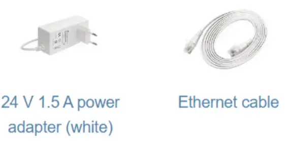
- Plug the included power adapter to start up the device (see “Audience#Powering”).
- The device will boot up, front led indicator will light in solid blue, and the Wireless network will be available for connecting.
- Open network connections on your PC, mobile phone, or other device and search for MikroTik wireless network and connect to it.
- Once connected to the wireless network, open https://192.168.88.1 in your web browser to start configuration, since there is no password by default, you will be logged automatically. For mobile phones use the application (see “Audience#MikroTik mobile app”).
- We recommend clicking the “Check for updates” button and updating your RouterOS software to the latest version to ensure the best performance and stability.
- Choose your country, apply country regulation settings, and set up your password on the screen that loads.
To add another Audience device to the network (see “Audience#WPS Sync button”).
MikroTik mobile app
Use the MikroTik smartphone app to configure your router in the field, or to apply the most basic initial settings for your MikroTik home access point.
https://mikrotik.com/mobile_app
- Scan QR code and choose your preferred OS.
- Install and open application.
- By default, the IP address and user name will be already entered.
- Click Connect to establish a connection to your device through a wireless network.
- Choose Quick setup and the application will guide you through all basic configuration settings in a couple of easy steps.
- An advanced menu is available to fully configure all necessary settings.
Powering
The device accepts power from the power jack or from the Ethernet port:
- Provided direct-input power jack (5.5 mm outside and 2 mm inside, female, pin positive plug) accepts 12-57 V DC ⎓.
- Ethernet 1 port accepts Power over Ethernet 802.3af/at 24-57 V DC ⎓.
The power consumption under maximum load can reach 30 W.
Connecting to a POE Adapter. POE adapter is not included in a package, if you consider using it, please follow these steps:
- Connect the Ethernet cable from the Audience to the POE port of the POE adapter.
- Connect an Ethernet cable from your LAN to the LAN port of the POE adapter, please mind arrows for data and power flow.
- Connect the power cord to the adapter, and then plug the power cord into a power outlet.
Mounting
The device is designed to be used indoors and placed on a flat surface with all needed cables connecting to the back of the unit. The IPX rating scale of IPX0. We recommend using Cat6 shielded cable for Audience devices.
Warning! This equipment should be installed and operated with a minimum distance of 20 cm between the device and your body. The operation of this equipment in the residential environment could cause radio interference.
Configuration
Once logged in, we recommend clicking the “Check for updates” button in the QuickSet menu, as updating your RouterOS software to the latest version ensures the best performance and stability. For wireless models, please make sure you have selected the country where the device will be used, to conform with local regulations.
RouterOS includes many configuration options in addition to what is described in this document. We suggest starting here to get yourself accustomed to the possibilities: https://mt.lv/help. In case IP connection is not available, the Winbox tool (https://mt.lv/winbox) can be used to connect to the MAC address of the device from the LAN side (all access is blocked from the Internet port by default).
For recovery purposes, it is possible to boot the device for reinstallation, see section Audience#Buttons and Jumpers.
Expansion slots and ports
Two Gigabit Ethernet ports.
Integrated Wireless 2.4 GHz 802.11b/g/n, antenna gain 3.5 dB
https://help.mikrotik.com/docs/display/UM/Audience
- Integrated Wireless 5.0 GHz 802.11a/n/ac, antenna gain 4.5 dBi. 5180 – 5320 MHz.
- Integrated Wireless 5.0 GHz 802.11a/n/ac, antenna gain 4.5 dBi. 5500 – 5825 MHz.
Buttons and Jumpers
The reset button functions as described below:
- Hold this button before applying power, release after three seconds since powering, to load backup Boot loader. This might be necessary if the device is not operating because of a failed RouterBOOT upgrade. When you have started the device with the backup loader, you can either set RouterOS to force the backup loader in the RouterBOARD settings or have a chance to reinstall the failed RouterBOOT from an fwf file (total 3 seconds).
- If you keep holding this button for 2 more seconds until the green LED light starts flashing, release the button to reset the RouterOS configuration to default (total 5 seconds).
To connect this device to a wireless network managed by CAPsMAN, keep holding the button for 5 more seconds, LED turns solid green, release now to turn on CAPs mode (total 10 seconds). - Or Keep holding the button for 5 more seconds until the green LED turns off, then release it to make the RouterBOARD look for Netinstall servers. You can also simply keep the button pressed until the device shows up in the Netinstall program on Windows (total 15 seconds).
Regardless of the above option used, the system will load the backup RouterBOOT loader if the button is pressed before power is applied to the device. Useful for RouterBOOT debugging and recovery.
WPS Sync button
Use the WPS Sync button to expand your wireless repeater network coverage by adding multiple Audience devices to it.
- On the chosen Audience AP, push the “WPS-Sync” button once, to turn on WPS mode for two minutes and make it wait for the Audience repeater. The status LED will blink green.
- The Audience repeater needs to be booted with a pressed “WPS-Sync” button for the device to configure itself according to the “WPS-Sync” mode and to connect to the Audience AP. Release the “WPS-Sync” button when the status LED is blinking amber.
- If the Audience repeater fails to connect to the Audience AP, then connecting can be repeated through RouterOS or by pressing the “WPS-Sync” button and releasing after 5 seconds, the device will turn on “WPS-Sync” mode for two minutes and search for Audience AP. Status LED will blink amber.
- To add a third Audience repeater to your network, push the “WPS-Sync” button on the second Audience in your network, then boot the third unit with the “WPS-Sync” button pressed. Repeat with as many units as needed, adding more devices to your network.
Front status LED behavior
- Solid blue – the device is powered on.
- Blinking green – the device is in Access Point mode and waits for another Audience device to be connected.
- Blinking amber (Red + Green) – the device searches and tries to connect to another Audience device.
- Solid green – the device has established a connection in an Audience network.
- Blinking Red – the device runs radar detection for Dynamic Frequency Selection (DFS).
Accessories
Specifications
For more information about this product, specifications and pictures please visit our web page: https://mikrotik.com/product/audience
Operating system support
The device supports RouterOS software version 6. The specific factory-installed version number is indicated in the RouterOS menu /system resource. Other operating systems have not been tested.
Notice
- The Frequency band 5.470-5.725 GHz isn’t allowed for commercial use.
- In case WLAN devices work with different ranges than the above regulations, then a customized firmware version from the manufacturer/supplier is required to be applied to the end-user equipment and also prevent the end-user from reconfiguration.
- For Outdoor Usage: End-user requires approval/license from the NTRA.
- Datasheet for any device is available on the official manufacturer website.
- Products with the letters “EG” at the end of their serial number have their wireless frequency range limited to 2.400 – 2.4835 GHz, the TX power is limited to 20dBm (EIRP).
- Products with the letters “EG” at the end of their serial number have their wireless frequency range limited to 5.150 – 5.250 GHz, the TX power is limited to 23dBm (EIRP).
- Products with the letters “EG” at the end of their serial number have their wireless frequency range limited to 5.250 – 5.350 GHz, the TX power is limited to 20dBm (EIRP).
Please make sure the device has a locking package (firmware version from the manufacturer) which is required to be applied to the end-user equipment to prevent the end-user from reconfiguration. The product will be marked with country code “-EG”. This device needs to be upgraded to the latest version to ensure compliance with local authority regulations! It is the end users’ responsibility to follow local country regulations, including operation within legal frequency channels, output power, cabling requirements, and Dynamic Frequency Selection (DFS) requirements. All MikroTik radio devices must be professionally installed.
Federal Communication Commission Interference Statement
https://help.mikrotik.com/docs/display/UM/Audience
FCC ID:TV7D25-5HPQ2HP
This equipment has been tested and found to comply with the limits for a Class B digital device, pursuant to Part 15 of the FCC Rules. These limits are designed to provide reasonable protection against harmful interference in a residential installation.
This equipment generates, uses and can radiate radio frequency energy and, if not installed and used in accordance with the instructions, may cause harmful interference to radio communications. However, there is no guarantee that interference will not occur in a particular installation. If this equipment does cause harmful interference to radio or television reception, which can be determined by turning the equipment off and on, the user is encouraged to try to correct the interference by one of the following measures:
- Reorient or relocate the receiving antenna.
- Increase the separation between the equipment and receiver.
- Connect the equipment into an outlet on a circuit different from that to which the receiver is connected.
- Consult the dealer or an experienced radio/TV technician for help.
FCC Caution: Any changes or modifications not expressly approved by the party responsible for compliance could void the user’s authority to operate this equipment.
This device complies with Part 15 of the FCC Rules. Operation is subject to the following two conditions: (1) This device may not cause harmful interference, and (2) this device must accept any interference received, including interference that may cause undesired operation. This device and its antenna must not be co-located or operating in conjunction with any other antenna or transmitter.
IMPORTANT: Exposure to Radio Frequency Radiation.
This equipment complies with the FCC RF radiation exposure limits set forth for an uncontrolled environment. This equipment should be installed and operated with a minimum distance of 20 cm between the radiator and any part of your body.
For use of CBRS bands, the CBSD Category of the final Host equipment will be dependent on the power settings and antenna gain used.
Industry Canada
IC:7442A-D255HPQ2HP
This device complies with Industry Canada’s license-exempt RSS standard(s). Operation is subject to the following two conditions: (1) this device may not cause interference, and (2)
this device must accept any interference, including interference that may cause undesired operation of the device.
IMPORTANT: Exposure to Radio Frequency Radiation.
This equipment complies with the IC radiation exposure limits set forth for an uncontrolled environment. This equipment should be installed and operated with a minimum distance of 20 cm between the radiator and any part of your body.
CE Declaration of Conformity
Manufacturer: Mikrotik SIA, Brivibas gatve 214i Riga, Latvia, LV1039.
Hereby, Mikrotīkls SIA declares that the radio equipment type RouterBOARD is in compliance with Directive 2014/53/EU. The full text of the EU declaration of conformity is available at the following internet address: https://mikrotik.com/products
MPE statement
This equipment complies with EU radiation exposure limits set forth for an uncontrolled environment. This equipment should be installed and operated with a minimum distance of 20 cm between the radiator and your body unless specifically stated otherwise in page 1 of this document. In RouterOS you must specify your country, to make sure local wireless regulations are observed.
Frequency bands terms of use
| Frequency range (for applicable models) | Channels used | Maximum Output Power (EIRP) | Restriction |
| 2412-2472 MHz | 1 – 13 | 20 dBm | Without any restriction to use in all EU Member States |
| 5150-5250 MHz | 26 – 48 | 23 dBm | Restricted to indoor use only* |
| 5250-5350 MHz | 52 – 64 | 20 dBm | Restricted to indoor use only* |
| 5470-5725 MHz | 100 – 140 | 27 dBm | Without any restriction to use in all EU Member States |
* It is the customer’s responsibility to follow local country regulations, including operation within legal frequency channels, output power, cabling requirements, and Dynamic Frequency Selection (DFS) requirements. All Mikrotik radio devices must be professionally installed!
Note. The information contained here is subject to change. Please visit the product page on www.mikrotik.com for the most up-to-date version of this documen
EN. Instruction manual: Connect the power adapter to turn on the device. Open 192.168.88.1 in your web browser, to configure it. More information on {+}https://mt.lv/help+
https://help.mikrotik.com/docs/display/UM/Audience
More Manuals From Mikrotik
ManualsPro
Mikrotik
mikroTIK LTE18 ax mANTBox 52 15s Routers and Wireless User Manual
- June 13, 2024
- Mikrotik
Table of Contents
- Safety Warnings
- First use
- Powering
- Mounting
- Configuration
- Grounding
- Opening cover
- Expansion Slots and Ports
- Buttons and Jumpers
- Accessories
- Operating system support
- CE Declaration of Conformity
- References
- Read User Manual Online (PDF format)
- Download This Manual (PDF format)
LTE18 ax mANTBox 52 15s Routers and Wireless User Manual – mANTBox 52
15s
Safety Warnings
Before you work on any equipment, be aware of the hazards involved with
electrical circuitry, and be familiar with standard practices for preventing
accidents.
Read the installation instructions before connecting the system to the power
source.
This equipment is to be installed by trained and qualified personnel, as per
these installation instructions. The installer is responsible for obtaining
any required local or national safety inspections of the structural integrity
of the installation by the local authority/inspection department.
All installation methods for mounting an access point on any wall surface are
subject to the acceptance of local jurisdiction.
The Installation of the equipment must comply with local and national
electrical codes.
This unit is intended to be mounted outdoors on a pole. Please read the
mounting instructions carefully before beginning installation.
Failure to use the correct hardware and configuration or to follow the correct
procedures could result in a hazardous situation to people and damage to the
system.
We cannot guarantee that no accidents or damage will occur due to the improper
use of the device.
Please use this product with care and operate at your own risk.
This device needs to be upgraded to RouterOS v6.46 or the latest version to
ensure compliance with local authority regulations.
Exposure to Radio Frequency Radiation: This MikroTik equipment complies with
the FCC, IC, and European Union radiation exposure limits set forth for an
uncontrolled environment. This MikroTik device should be installed and
operated no closer than 20 centimeters from your body, occupational user, or
the general public.
First use
- Open cover (see Opening cover).
- Connect the Ethernet cable from your PC to the Ethernet port.
- Plug the device into the power source (see Powering).
- Download the Winbox (see Configuration).
- Open and search the MAC address in the Neighbors tab.
- Click on the MAC address and connect.
- The default IP is not set, the user name: is admin and there is no password (or, for some models, check user and wireless passwords on the sticker).
- Update the device to the latest RouterOS version, and make sure that the device has an internet connection https://mt.lv/configuration.
- Set a Country, to make sure local regulations are observed.
- Set the antenna gain, depending on the antenna used.
- Set up your password.
- To manually update the device, please go to https://mikrotik.com/download.
- Choose (ARM) packages for this device and download them to your PC.
- Upload downloaded packages to the (Winbox) (Files) menu and reboot the device.
- Updating your RouterOS software to the latest version will ensure the best performance, stability, and pdates, https://mt.lv/upgrade.
Powering
The device accepts power in the following ways:
• The Ethernet port accepts 802.3af/at PoE 12-57 V DC .
• Direct-input power jack (5.5 mm outside and 2 mm inside, female, pin
positive plug) accepts 12-57 V ⎓DC .
The power consumption under maximum load can reach 21 W.
Connecting to a PoE Adapter:
- Connect the Ethernet cable from the device to the PoE+DATA port of the PoE adapter;
- Connect an Ethernet cable from your local network (LAN) to the PoE adapter;
- Connect the power cord to the adapter, and then plug the power cord into a power outlet.
Mounting
The mANTbox comes with a QuickMount adapter that can be attached to a wall
using the included screws, or attached to a pole, using the included metal
mounting ring. The QuickMount allows the device to be adjusted horizontally
and vertically.
- Attach the quick mount to the back of the device.
- Attach the device to the pole and secure it with a provided steel clamp. Clamping diameter 35 – 70 mm.
- Please avoid connecting a loose Ethernet cable to the Ethernet port, secure the cable to a wall or the pole, so that the cable weight is not pulling the port. It is recommended to secure the Ethernet cable less than 2m from the device. This is to ensure that the cable doesn’t damage the port by its weight, or doesn’t fall out.
We recommend using Cat6 shielded cables.
Warning! This equipment should be installed and operated with a minimum
distance of 25 cm between the device and your body. The operation of this
equipment in the residential environment could cause radio interference.
Configuration
We recommend clicking the “Check for updates” button and updating your
RouterOS software to the latest version to ensure the best performance and
stability. RouterOS includes many configuration options in addition to what is
described in this document. We suggest visiting the RouterOS documentation
page to get yourself accustomed to the possibilities: https://mt.lv/help.
In case an IP connection is not available, the Winbox tool
(https://mt.lv/winbox) can be used to connect to the MAC address of the
device from the LAN side (all access is blocked from the internet port by
default).
First-time configuration https://mt.lv/configuration;
The device upgrade https://mt.lv/upgrade;
Grounding
The installation infrastructure (towers and masts), as well as the router
itself, must be properly grounded. The device includes a grounding wire
attachment screw behind the case door. Attach your grounding wire to the
grounding screw, then attach the other end of the grounding wire to the
grounded mast. This is to substantially reduce the risk of ESD and lightning
damage. The device includes a grounding connection (marked⏚ ).
Opening cover
To open the cover, please turn the captive screw by hand anti-clockwise and
lift it.
Expansion Slots and Ports
• Built-in wireless interface 5 GHz and 2.4 GHz.
• One SFP port for 1.25GBit modules, DDMI support.
• Gigabit Ethernet port, supporting automatic cross/straight cable correction
(Auto MDI/X), so you can use either straight or crossover cable for connecting
to other network devices.
Buttons and Jumpers
The reset button has the following functions:
• Hold this button during boot time until LED light starts flashing, release
the button to reset RouterOS configuration (total 5 seconds).
• Keep holding for 5 more seconds, LED turns solid, release now to turn on CAP
mode. The device will now look for a CAPsMAN server (total 10 seconds).
• Or Keep holding the button for 5 more seconds until LED turns off, then
release it to make the RouterBOARD look for Netinstall servers (total 15
seconds).
Regardless of the above option used, the system will load the backup
RouterBOOT loader if the button is pressed before power is applied to the
device. Useful for RouterBOOT debugging and recovery.
Accessories
The package includes the following accessories that come with the device:
• Switching Power Supply DC⎓ 24 V;
• Hose Clamp, 35-70 mm;
• Fastening set K-41;
• Gigabit POE injector cable with shielded connector;
• Mounting bracket.
Please visit wiki pages for the MikroTik SFP module compatibility table:
https://wiki.mikrotik.com/wiki/MikroTik_SFP_module_compatibility_table
Operating system support
The device supports RouterOS software version 6.46. The specific factory-
installed version number is indicated in the RouterOS menu /system resource.
Other operating systems have not been tested.
To avoid pollution of the environment, please separate the device from
household waste and dispose of it in a safe manner, such as in designated
waste disposal sites. Familiarize yourself with the procedures for the proper
transportation of the equipment to the designated disposal sites in your area.
Federal Communication Commission Interference Statement
| Model | FCC ID |
|---|---|
| RBD22UGS-5HPacD2HnD15S | TV7D2352A C |
This equipment has been tested and found to comply with the limits for a Class
A digital device, pursuant to Part 15 of the FCC Rules. These limits are
designed to provide reasonable protection against harmful interference in a
commercial installation. This equipment generates, uses, and can radiate radio
frequency energy and, if not installed and used in accordance with the
instruction manual, may cause harmful interference to radio communications.
Operation of this equipment in a residential area is likely to cause harmful
interference in which case the user will be required to correct the
interference at his own expense.
FCC Caution: Any changes or modifications not expressly approved by the
party responsible for compliance could void the user’s authority to operate
this equipment.
This device complies with Part 15 of the FCC Rules. Operation is subject to
the following two conditions: (1) This device may not cause harmful
interference, and (2) this device must accept any interference received,
including interference that may cause undesired operation.
Note: This unit was tested with shielded cables on the peripheral
devices. Shielded cables must be used with the unit to ensure compliance.
Antenna Installation WARNING: It is the installer’s responsibility to ensure
that when using the authorized antennas in the USA (or where FCC rules apply);
only those antennas certified with the product are to be used. The installer
should configure the output power level of antennas, according to country
regulations and per antenna type. Professional installation is required for
equipment with connectors to ensure compliance with health and safety issues.
LIST OF APPROVED 2.4 GHz ANTENNAS:
3.6 dBi Dipole Antenna (Model: HGO-antenna-OUT)
5 dBi Dipole Antenna HP (Model: DA-2450-05RP-SMA-01 (ACOMNIRPSMA))
LIST OF APPROVED 5 GHz ANTENNAS:
6.68 dBi Dipole Antenna (Model: HGO-antenna-OUT)
19 dBi Sector Antenna (Model: MTAS-5G-19D120)
30 dBi Parabolic Dish Antenna (Model: MTAS-5G-30D3)
The same type of antenna and lower antenna gain than those listed above may
also be used in accordance with the certification.
IMPORTANT: Exposure to Radio Frequency Radiation.
This equipment complies with the FCC radiation exposure limits set forth for
an uncontrolled environment. This equipment should be installed and operated
with a minimum distance of 20 cm between the radiator and any part of your
body.
Innovation, Science and Economic Development Canada
| Model | IC |
|---|---|
| RBD22UGS-5HPacD2HnD15S | 7442AD2352AC |
This device contains license-exempt transmitter(s)/receiver(s) that comply
with Innovation, Science, and Economic Development Canada’s license-exempt
RSS(s). Operation is subject to the following two conditions: (1) This device
may not cause interference. (2) This device must accept any interference,
including interference that may cause undesired operation of the device.
This Class A digital apparatus complies with Canadian ICES-003.
CAN ICES-003 (A) / NMB-003 (A)
The device for operation in the band 5150–5250 MHz is only for indoor use to
reduce the potential for harmful interference to co-channel mobile satellite
systems.
Antenna Installation WARNING: It is the installer’s responsibility to
ensure that when using the authorized antennas in Canada (or where IC rules
apply); only those antennas certified with the product are to be used. The
installer should configure the output power level of antennas, according to
country regulations and per antenna type. Professional installation is
required for equipment with connectors to ensure compliance with health and
safety issues.
LIST OF APPROVED 2.4 GHz ANTENNAS:
3.6 dBi Dipole Antenna (Model: HGO-antenna-OUT)
5 dBi Dipole Antenna HP (Model: DA-2450-05RP-SMA-01(ACOMNIRPSMA))
LIST OF APPROVED 5 GHz ANTENNAS:
6.68 dBi Dipole Antenna (Model: HGO-antenna-OUT)
19 dBi Sector Antenna (Model: MTAS-5G-19D120)
30 dBi Parabolic Dish Antenna (Model: MTAS-5G-30D3)
The same type of antenna and lower antenna gain than those listed above may
also be used in accordance to certification
IMPORTANT: Exposure to Radio Frequency Radiation.
This equipment complies with the IC radiation exposure limits set forth for an
uncontrolled environment. This equipment should be installed and operated with
a minimum distance of 20 cm between the radiator and any part of your body.
UKCA Marking Eurasian Conformity Mark
CE Declaration of Conformity
Manufacturer: Mikrotikls SIA, Brivibas gatve 214i Riga, Latvia, LV1039.
Hereby, Mikrotīkls SIA declares that the radio equipment type RBD22UGS-
5HPacD2HnD-15S is in compliance with Directive 2014/53/EU. The full text of
the EU declaration of conformity is available at the following internet
address: https://mikrotik.com/products
Frequency bands terms of use
Frequency range (for applicable models)| Channels used| Maximum Output Power
(EIRP)| Restriction
—|—|—|—
2412-2472 MHz| 1 – 13| 20 dBm| Without any restriction to use in all EU Member
States
5150-5250 MHz| 26 – 48| 23 dBm| Restricted to indoor use only
5250-5350 MHz| 52 – 64| 20 dBm| Restricted to indoor use only
5470-5725 MHz| 100 – 140| 27 dBm| Without any restriction to use in
all EU Member States
- It is the customer’s responsibility to follow local country regulations, including operation within legal frequency channels, output power, cabling requirements, and Dynamic Frequency Selection (DFS) requirements. All Mikrotik radio devices must be professionally installed!
This MikroTik device meets Maximum WLAN transmit power limits per ETSI
regulations. For more detailed information see Declaration of Conformity above
The WLAN function for this device is restricted to indoor use only when
operating in the 5150 to 5350 MHz frequency range.
Note. The information contained here is subject to change. Please visit the
product page on www.mikrotik.com for the most up to
date version of this document.
References
- MikroTik Routers and Wireless
- MikroTik Routers and Wireless — Buy
- MikroTik Routers and Wireless — Buy
- MikroTik Routers and Wireless — Software
- MikroTik SFP module compatibility table — MikroTik Wiki
Read User Manual Online (PDF format)
Read User Manual Online (PDF format) >>
Download This Manual (PDF format)
Download this manual >>
Сегодня хочу показать, как можно быстро настроить маршрутизаторы MikroTik в режиме точки доступа. Покажу на примере CAP AC, но действия будут точно такими же для любой модели.
Видеоуроки по настройке MikroTik
Нет возможности пройти очный тренинг MTCNA? Ему есть альтернатива. Минус – не будет официального сертификата. Плюсов гораздо больше. Во-первых, не надо никуда ехать, смотрите и пересматривайте видеоуроки тогда, когда вам удобно и столько раз, сколько нужно. Во-вторых, в курсе упор на практику, ее примерно в 4 раза больше, чем на очном обучении. Подробнее о курсе на странице «Настройка оборудования MikroTik», там же можно заказать бесплатно первые 25 уроков.
Если вы хотите настроить устройство в режиме роутера – то есть эта статья.
Собственно, подключаем устройство к сети, открываем winbox. CAP AC должен будет появиться во вкладке neighbors. На время настройки, лучше подключиться по мак адресу. По умолчанию используется имя пользователя admin, без пароля (на скришносте у меня забиты имя и пароль, на это внимание не обращайте).

Для начала – обновимся – идем в system – packages, жмем check for updates, если есть обновления жмем download and install. Дожидаемся пока устройство перезагрузится.

После этого идем в system – routerboard и жмем кнопку Upgrade. После этого перезагружаем устройство – system -reboot.

Дальше сбросим все настройки – system – reset configuration. Ставим галки – no default configuration и do not backup. Дожидаемся очередной перезагрузки. И подключаемся, когда устройство появится в neighbors.

Первым делом, т.к. наше устройство будет работать в режиме точки доступа – добавим все интерфейсы в один бридж, и зададим ему ip адрес из вашей сети.
В меню bridge, в первой вкладке добавим новый мост (нужно нажать на плюс), назовем его к примеру lan, во второй вкладке ports – добавим интерфейсы к созданному бриджу, т.к. мы хотим добавить все интерфейсы – выбираем all.


Задаем адрес – ip – addresses, и для интерфейса lan прописываем свободный адрес из нашей сети.
После чего, чтобы у точки доступа был доступ к интернету, добавим маршрут по умолчанию. IP – Routes, в качестве шлюза нужно указать адрес вашего основного роутера, в моем случае это 192.168.1.1

Зададим адрес DNS сервера – IP – DNS, и указываем нужный адрес (это либо адрес вашего роутера, либо провайдера, либо, к примеру гугловый – 8.8.8.8)

Если вы не хотите задавать статический адрес, то можете настроить dhcp клиент. (ip-dhcp-client).
Осталось только включить WiFi. Идем в Wireless – Security Profiles, добавим новый профиль – выбираем wpa2 psk, wpa2 eap, в графе WPA2 Pre-Shared Key вводим пароль от wifi сети.

Далее идем в WiFi Interfaces и заходим в свойства каждого адаптера, выбираем mode – ap bridge, страну – Россия, что бы не нарушать закон, касательно мощности передатчиков, задаем ssid (видимое имя сети) и наш созданный ранее security profile, для 2.4 ГГц, я обычно ставлю ширину канала 20/40MHz CE, для 5ГГц – 20/40/80MHz Ceee. Если покажется что WiFi слабо бьет – можно будет поиграться с этим параметром. Чем уже канал, тем дальше точка доступа бьет, но тем медленнее будет интернет. Так же можно указать частоту, или канал, в зависимости от загруженности в вашем районе. Остальное можно пока оставить по умолчанию. С такими настройками WiFi должен работать и интернет на устройствах должен идти. Если хотите более глубоких настроек, то можете поиграться, с шириной канала, мощностью и т.д. Wiki от микротик в помощь, там все относительно подробно описано про каждый из параметров.


В заключение, дадим понятное имя роутеру, и зададим пароль, чтобы абы-кто не лез в настройки.
System – Identity – тут вбиваем имя устройства.

System – Users – правой кнопкой по пользователю – password – задаем пароль. Базовая настройка завершена.

Видеоуроки по настройке MikroTik
Нет возможности пройти очный тренинг MTCNA? Ему есть альтернатива. Минус – не будет официального сертификата. Плюсов гораздо больше. Во-первых, не надо никуда ехать, смотрите и пересматривайте видеоуроки тогда, когда вам удобно и столько раз, сколько нужно. Во-вторых, в курсе упор на практику, ее примерно в 4 раза больше, чем на очном обучении. Подробнее о курсе на странице «Настройка оборудования MikroTik», там же можно заказать бесплатно первые 25 уроков.