

Cat. No. I546-E1-02
0675398-6B
SETUP MANUAL
SYSDRIVE 3G3JV
Compact Simplified Inverters

Thank you for choosing this SYSDRIVE 3G3JV-series product. Proper use
and handling of the product will ensure proper product performance, will
lengthen product life, and may prevent possible accidents.
Please read this manual thoroughly and handle and operate the product
with care.
1. To ensure safe and proper use of the OMRON Inverters, please read this SETUP
MANUAL and the USER’S MANUAL (Cat. No. I528-E1) to gain sufficient knowledge
of the devices, safety information, and precautions before actual use.
2. The products are illustrated without covers and shieldings for closer look in this SETUP MANUAL and the USER’S MANUAL. For actual use of the products, make sure to
use the covers and shieldings as specified.
3. This SETUP MANUAL and other related user’s manuals are to be delivered to the actual end users of the products.
4. Please keep this manual close at hand for future reference.
5. If the product has been left unused for a long time, please inquire at our sales representative.
NOTICE
1. This manual describes the functions of the product and relations with other
products. You should assume that anything not described in this manual is
not possible.
2. Although care has been given in documenting the product, please contact your
OMRON representative if you have any suggestions on improving this manual.
3. The product contains potentially dangerous parts under the cover. Do not attempt
to open the cover under any circumstances. Doing so may result in injury or death
and may damage the product. Never attempt to repair or disassemble the product.
4. We recommend that you add the following precautions to any instruction manuals
you prepare for the system into which the product is being installed.
S Precautions on the dangers of high-voltage equipment.
S Precautions on touching the terminals of the product even after power has been
turned OFF. (These terminals are live even with the power turned OFF.)
5. Specifications and functions may be changed without notice in order to improve
product performance.
Items to Check Before Unpacking
Check the following items before removing the product from the package:
S Has the correct product been delivered (i.e., the correct model number and speci-
fications)?
S Has the product been damaged in shipping?
S Are any screws or bolts loose?

Notice:
OMRON products are manufactured for use according to proper procedures by a qualified
operator and only for the purposes described in this manual.
The following conventions are used to indicate and classify precautions in this manual. Always heed the information provided with them. Failure to heed precautions can result in injury to people or damage to property.
!
DANGER Indicates an imminently hazardous situation which, if not avoided, will result in death
or serious injury. Additionally, there may be severe property damage.
WARNING Indicates a potentially hazardous situation which, if not avoided, could result in death
!
or serious injury. Additionally, there may be severe property damage.
Caution Indicates a potentially hazardous situation which, if not avoided, may result in minor
!
or moderate injury, or property damage.
OMRON Product References
All OMRON products are capitalized in this manual. The word “Unit” is also capitalized when
it refers to an OMRON product, regardless of whether or not it appears in the proper name
of the product.
The abbreviation “Ch,” which appears in some displays and on some OMRON products,
often means “word” and is abbreviated “Wd” in documentation in this sense.
The abbreviation “PC” means Programmable Controller and is not used as an abbreviation
for anything else.
Visual Aids
The following headings appear in the left column of the manual to help you locate different
types of information.
Note Indicates information of particular interest for efficient and convenient operation of the product.
OMRON, 2005
All rights reserved. No part of this publication may be reproduced, stored in a retrieval system, or transmitted,
in any form, or by any means, mechanical, electronic, photocopying, recording, or otherwise, without the prior
written permission of OMRON.
No patent liability is assumed with respect to the use of the information contained herein. Moreover, because
OMRON is constantly striving to improve its high-quality products, the information contained in this manual
is subject to change without notice. Every precaution has been taken in the preparation of this manual. Nevertheless, OMRON assumes no responsibility for errors or omissions. Neither is any liability assumed for damages resulting from the use of the information contained in this publication.
Read and Understand this Manual
Please read and understand this manual before using the product. Please consult your OMRON
representative if you have any questions or comments.
Warranty and Limitations of Liability
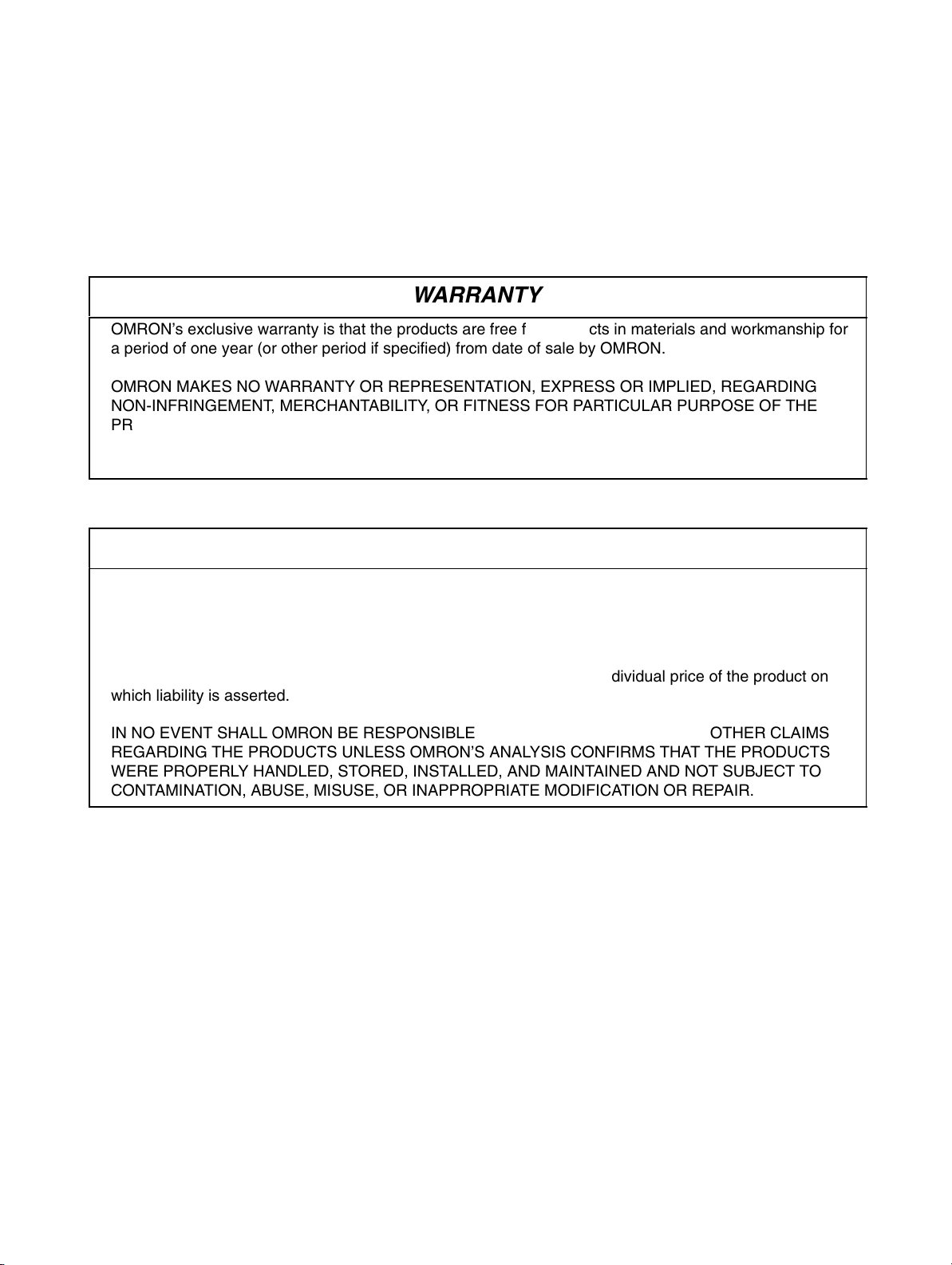
WARRANTY
OMRON’s exclusive warranty is that the products are free from defects in materials and workmanship for
БББББББББББББББББББББББББББББББ
a period of one year (or other period if specified) from date of sale by OMRON.
БББББББББББББББББББББББББББББББ
БББББББББББББББББББББББББББББББ
OMRON MAKES NO WARRANTY OR REPRESENTATION, EXPRESS OR IMPLIED, REGARDING
NON-INFRINGEMENT, MERCHANTABILITY, OR FITNESS FOR PARTICULAR PURPOSE OF THE
БББББББББББББББББББББББББББББББ
PRODUCTS. ANY BUYER OR USER ACKNOWLEDGES THAT THE BUYER OR USER ALONE HAS
БББББББББББББББББББББББББББББББ
DETERMINED THAT THE PRODUCTS WILL SUITABLY MEET THE REQUIREMENTS OF THEIR
БББББББББББББББББББББББББББББББ
INTENDED USE. OMRON DISCLAIMS ALL OTHER WARRANTIES, EXPRESS OR IMPLIED.
БББББББББББББББББББББББББББББББ
LIMITATIONS OF LIABILITY
OMRON SHALL NOT BE RESPONSIBLE FOR SPECIAL, INDIRECT, OR CONSEQUENTIAL
DAMAGES, LOSS OF PROFITS OR COMMERCIAL LOSS IN ANY WAY CONNECTED WITH THE
БББББББББББББББББББББББББББББББ
PRODUCTS, WHETHER SUCH CLAIM IS BASED ON CONTRACT, WARRANTY, NEGLIGENCE, OR
БББББББББББББББББББББББББББББББ
STRICT LIABILITY.
БББББББББББББББББББББББББББББББ
In no event shall the responsibility of OMRON for any act exceed the individual price of the product on
БББББББББББББББББББББББББББББББ
which liability is asserted.
БББББББББББББББББББББББББББББББ
БББББББББББББББББББББББББББББББ
IN NO EVENT SHALL OMRON BE RESPONSIBLE FOR WARRANTY, REPAIR, OR OTHER CLAIMS
REGARDING THE PRODUCTS UNLESS OMRON’S ANALYSIS CONFIRMS THAT THE PRODUCTS
БББББББББББББББББББББББББББББББ
WERE PROPERLY HANDLED, STORED, INSTALLED, AND MAINTAINED AND NOT SUBJECT TO
БББББББББББББББББББББББББББББББ
CONTAMINATION, ABUSE, MISUSE, OR INAPPROPRIATE MODIFICATION OR REPAIR.
Application Considerations
БББББББББББББББББББББББББББББББ
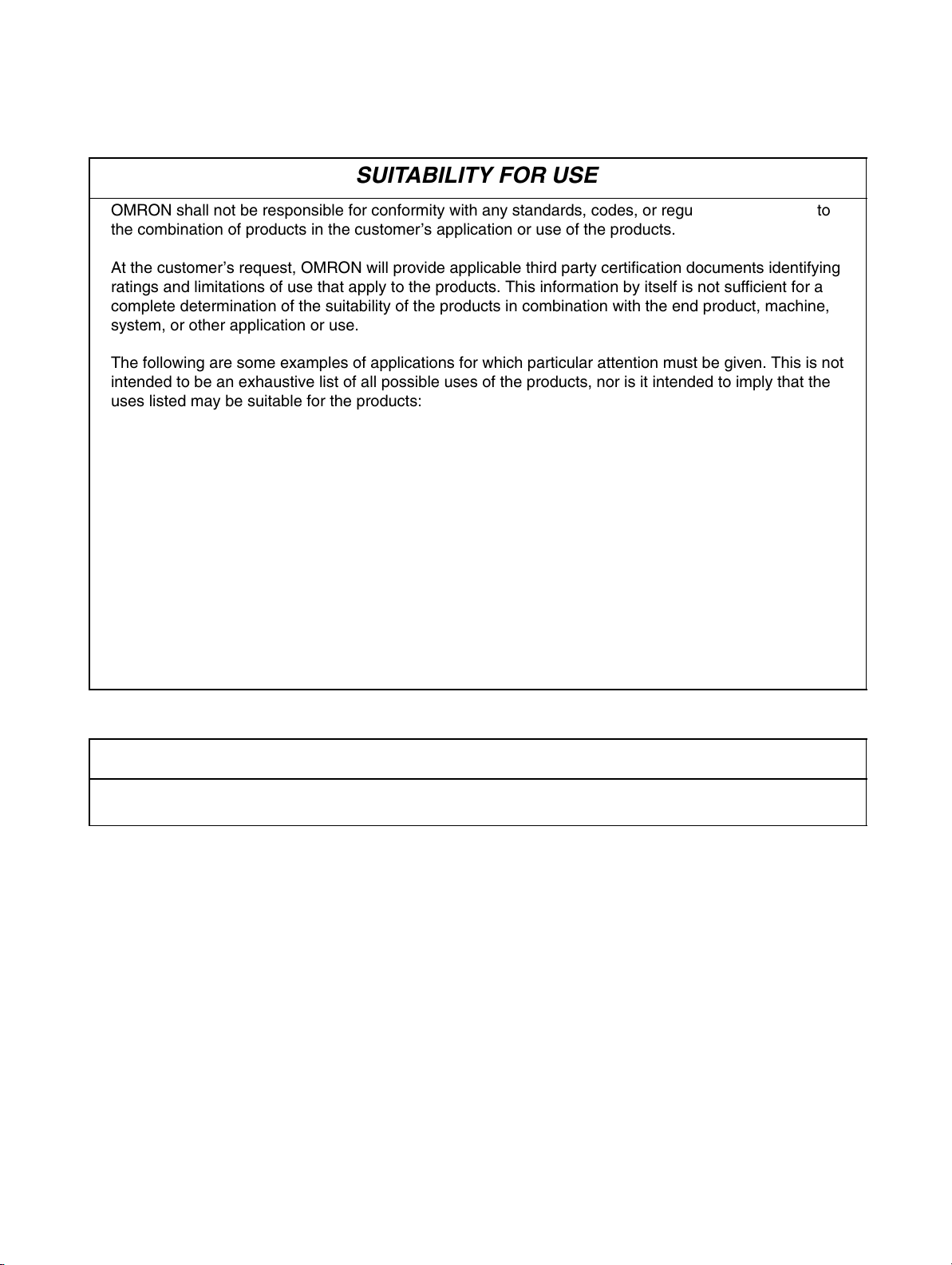
SUITABILITY FOR USE
OMRON shall not be responsible for conformity with any standards, codes, or regulations that apply to
the combination of products in the customer’s application or use of the products.
БББББББББББББББББББББББББББББББ
БББББББББББББББББББББББББББББББ
At the customer’s request, OMRON will provide applicable third party certification documents identifying
ratings and limitations of use that apply to the products. This information by itself is not sufficient for a
БББББББББББББББББББББББББББББББ
complete determination of the suitability of the products in combination with the end product, machine,
БББББББББББББББББББББББББББББББ
system, or other application or use.
БББББББББББББББББББББББББББББББ
БББББББББББББББББББББББББББББББ
The following are some examples of applications for which particular attention must be given. This is not
intended to be an exhaustive list of all possible uses of the products, nor is it intended to imply that the
БББББББББББББББББББББББББББББББ
uses listed may be suitable for the products:
БББББББББББББББББББББББББББББББ
• Outdoor use, uses involving potential chemical contamination or electrical interference, or conditions
БББББББББББББББББББББББББББББББ
or uses not described in this manual.
БББББББББББББББББББББББББББББББ
• Nuclear energy control systems, combustion systems, railroad systems, aviation systems, medical
БББББББББББББББББББББББББББББББ
equipment, amusement machines, vehicles, safety equipment, and installations subject to separate
БББББББББББББББББББББББББББББББ
industry or government regulations.
БББББББББББББББББББББББББББББББ
• Systems, machines, and equipment that could present a risk to life or property.
БББББББББББББББББББББББББББББББ
Please know and observe all prohibitions of use applicable to the products.
БББББББББББББББББББББББББББББББ
БББББББББББББББББББББББББББББББ
NEVER USE THE PRODUCTS FOR AN APPLICATION INVOLVING SERIOUS RISK TO LIFE OR
БББББББББББББББББББББББББББББББ
PROPERTY WITHOUT ENSURING THAT THE SYSTEM AS A WHOLE HAS BEEN DESIGNED TO
ADDRESS THE RISKS, AND THAT THE OMRON PRODUCTS ARE PROPERLY RATED AND
БББББББББББББББББББББББББББББББ
INSTALLED FOR THE INTENDED USE WITHIN THE OVERALL EQUIPMENT OR SYSTEM.
БББББББББББББББББББББББББББББББ
PROGRAMMABLE PRODUCTS
OMRON shall not be responsible for the user’s programming of a programmable product, or any
БББББББББББББББББББББББББББББББ
consequence thereof.

Disclaimers
БББББББББББББББББББББББББББББББ
CHANGE IN SPECIFICATIONS
Product specifications and accessories may be changed at any time based on improvements and other
reasons.
БББББББББББББББББББББББББББББББ
БББББББББББББББББББББББББББББББ
It is our practice to change model numbers when published ratings or features are changed, or when
БББББББББББББББББББББББББББББББ
significant construction changes are made. However, some specifications of the products may be
changed without any notice. When in doubt, special model numbers may be assigned to fix or establish
БББББББББББББББББББББББББББББББ
key specifications for your application on your request. Please consult with your OMRON representative
БББББББББББББББББББББББББББББББ
at any time to confirm actual specifications of purchased products.
БББББББББББББББББББББББББББББББ
DIMENSIONS AND WEIGHTS
Dimensions and weights are nominal and are not to be used for manufacturing purposes, even when
БББББББББББББББББББББББББББББББ
tolerances are shown.
БББББББББББББББББББББББББББББББ
PERFORMANCE DATA
Performance data given in this manual is provided as a guide for the user in determining suitability and
does not constitute a warranty. It may represent the result of OMRON’s test conditions, and the users
БББББББББББББББББББББББББББББББ
must correlate it to actual application requirements. Actual performance is subject to the OMRON
БББББББББББББББББББББББББББББББ
Warranty and Limitations of Liability.
БББББББББББББББББББББББББББББББ
ERRORS AND OMISSIONS
The information in this manual has been carefully checked and is believed to be accurate; however, no
responsibility is assumed for clerical, typographical, or proofreading errors, or omissions.
БББББББББББББББББББББББББББББББ

General Precautions
Observe the following precautions when using the SYSDRIVE Inverters and peripheral devices.
This manual may include illustrations of the product with protective covers removed in order
to describe the components of the product in detail. Make sure that these protective covers
are on the product before use.
Consult your OMRON representative when using the product after a long period of storage.
WARNING Do not touch the inside of the Inverter. Doing so may result in electrical shock.
!
WARNING Operation, maintenance, or inspection must be performed after turning OFF the
!
power supply, confirming that the CHARGE indicator (or status indicators) are OFF,
and after waiting for the time specified on the front cover. Not doing so may result in
electrical shock.
WARNING Do not damage, pull on, apply stress to, place heavy objects on, or pinch the cables.
!
Doing so may result in electrical shock.
WARNING Do not touch the rotating parts of the motor under operation. Doing so may result in
!
injury.
WARNING Do not modify the product. Doing so may result in injury or damage to the product.
!
Caution Do not store, install, or operate the product in the following places. Doing so may
!
result in electrical shock, fire or damage to the product.
S Locations subject to direct sunlight.
S Locations subject to temperatures or humidity outside the range specified in the
specifications.
S Locations subject to condensation as the result of severe changes in temperature.
S Locations subject to corrosive or flammable gases.
S Locations subject to exposure to combustibles.
S Locations subject to dust (especially iron dust) or salts.
S Locations subject to exposure to water, oil, or chemicals.
S Locations subject to shock or vibration.
Caution Do not touch the Inverter radiator, regenerative resistor, or Servomotor while the
!
power is being supplied or soon after the power is turned OFF. Doing so may result in
a skin burn due to the hot surface.
Caution Do not conduct a dielectric strength test on any part of the Inverter. Doing so may
!
result in damage to the product or malfunction.
Caution Take appropriate and sufficient countermeasures when installing systems in the fol-
!
lowing locations. Not doing so may result in equipment damage.
S Locations subject to static electricity or other forms of noise.
S Locations subject to strong electromagnetic fields and magnetic fields.
S Locations subject to possible exposure to radioactivity.
S Locations close to power supplies.

Transportation Precautions
Caution Do not hold by front cover or panel, instead, hold by the radiation fin (heat sink) while
!
transporting the product. Doing so may result in injury.
Caution Do not pull on the cables. Doing so may result in damage to the product or malfunc-
!
tion.
Caution Use the eye-bolts only for transporting the Inverter. Using them for transporting the
!
machinery may result in injury or malfunction.
Installation Precautions
WARNING Provide an appropriate stopping device on the machine side to secure safety. (A
!
holding brake is not a stopping device for securing safety.) Not doing so may result in
injury.
WARNING Provide an external emergency stopping device that allows an instantaneous stop of
!
operation and power interruption. Not doing so may result in injury.
Caution Be sure to install the product in the correct direction and provide specified clear-
!
ances between the Inverter and control panel or with other devices. Not doing so
may result in fire or malfunction.
Caution Do not allow foreign objects to enter inside the product. Doing so may result in fire or
!
malfunction.
Caution Do not apply any strong impact. Doing so may result in damage to the product or
!
malfunction.
Wiring Precautions
WARNING Wiring must be performed only after confirming that the power supply has been
!
turned OFF. Not doing so may result in electrical shock.
WARNING Wiring must be performed by authorized personnel. Not doing so may result in
!
electrical shock or fire.
WARNING Be sure to confirm operation only after wiring the emergency stop circuit. Not doing
!
so may result in injury.
WARNING Always connect the ground terminals to a ground of 100 Ω or less. Not connecting to
!
a proper ground may result in electrical shock.

Caution Install external breakers and take other safety measures against short-circuiting in
!
external wiring. Not doing so may result in fire.
Caution Confirm that the rated input voltage of the Inverter is the same as the AC power sup-
!
ply voltage. An incorrect power supply may result in fire, injury, or malfunction.
Caution Connect the Braking Resistor and Braking Resistor Unit as specified in the manual.
!
Not doing so may result in fire.
Caution Be sure to wire correctly and securely. Not doing so may result in injury or damage to
!
the product.
Caution Be sure to firmly tighten the screws on the terminal block. Not doing so may result in
!
fire, injury, or damage to the product.
Caution Do not connect an AC power to the U, V, or W output. Doing so may result in damage
!
to the product or malfunction.
Caution Set the multi-function contact input parameter for NC contact terminals (e.g., 3-wire
!
sequence) before wiring them. If the parameter’s default setting is used, the motor
may start running when the input terminal S2 is turned ON.
Operation and Adjustment Precautions
WARNING Turn ON the input power supply only after mounting the front cover, terminal covers,
!
bottom cover, Operator, and optional items. Not doing so may result in electrical
shock.
WARNING Do not remove the front cover, terminal covers, bottom cover, Operator, or optional
!
items while the power is being supplied. Doing so may result in electrical shock or
damage to the product.
WARNING Do not operate the Operator or switches with wet hands. Doing so may result in
!
electrical shock.
WARNING Do not touch the inside of the Inverter. Doing so may result in electrical shock.
!
WARNING Do not come close to the machine when using the error retry function because the
!
machine may abruptly start when stopped by an alarm. Doing so may result in injury.
WARNING Do not come close to the machine immediately after resetting momentary power
!
interruption to avoid an unexpected restart (if operation is set to be continued in the
processing selection function after momentary power interruption is reset). Doing so
may result in injury.

WARNING Provide a separate emergency stop switch because the STOP Key on the Operator
!
is valid only when function settings are performed. Not doing so may result in injury.
WARNING Be sure to confirm that the RUN signal is turned OFF before turning ON the power
!
supply, resetting the alarm, or switching the LOCAL/REMOTE selector. Doing so
while the RUN signal is turned ON may result in injury.
Caution Be sure to confirm permissible ranges of motors and machines before operation be-
!
cause the Inverter speed can be easily changed from low to high. Not doing so may
result in damage to the product.
Caution Provide a separate holding brake when necessary. Not doing so may result in injury.
!
Caution Do not perform a signal check during operation. Doing so may result in injury or dam-
!
age to the product.
Caution Do not carelessly change settings. Doing so may result in injury or damage to the
!
product.
Maintenance and Inspection Precautions
WARNING Do not touch the Inverter terminals while the power is being supplied.
!
WARNING Maintenance or inspection must be performed only after turning OFF the power
!
supply, confirming that the CHARGE indicator (or status indicators) is turned OFF,
and after waiting for the time specified on the front cover. Not doing so may result in
electrical shock.
WARNING Maintenance, inspection, or parts replacement must be performed by authorized
!
personnel. Not doing so may result in electrical shock or injury.
WARNING Do not attempt to take the Unit apart or repair. Doing either of these may result in
!
electrical shock or injury.
Caution Carefully handle the Inverter because it uses semiconductor elements. Careless
!
handling may result in malfunction.
Caution Do not change wiring, disconnect connectors, the Operator, or optional items, or re-
!
place fans while power is being supplied. Doing so may result in injury, damage to
the product, or malfunction.

Warnings for UL/cUL Marking
• Do not connect or disconnect wiring, or perform signal checks while the power supply is turned ON.
• The Inverter internal capacitor is still charged even after the power supply is turned OFF. To prevent
electrical shock, disconnect all power before servicing the Inverter. Then wait at least one minute after
the power supply is disconnected and all indicators are OFF.
• Do not perform a withstand voltage test on any part of the Inverter. This electronic equipment uses
semiconductors and is vulnerable to high voltage.
• Do not remove the Digital Operator or the blank cover unless the power supply is turned OFF. Never
touch the printed control board (PCB) while the power supply is turned ON.
• The Inverter is not suitable for use on a circuit capable of delivering more than 5,000 RMS symmetrical
amperes, 250 volts maximum (100-V-class Units).
• Take measures against overcurrent, overload, and overheating by using the Motor Protection Settings.
CAUTION
Use 75°C copper wires or equivalent.
Low voltage wires shall be wired with Class I Wiring.
H Motor Protection Settings
Rated Motor Current (n32)
• Set the rated motor current (n32) in order to prevent the motor from burning due to overloading.
• Check the rated current on the motor nameplate and set the parameter.
• This parameter is used for the electronic thermal function for motor overload detection (OL1). By set-
ting the correct parameter, the overloaded motor will be protected from burning.
n32 Rated Motor Current Changes during
operation
Setting
range
0.0% to 120% (A) of rated
output current of Inverter
Unit of
setting
0.1 A Default setting (see note 1)
No
Note 1. The standard rated current of the maximum applicable motor is the default rated motor cur-
rent.
Note 2. Motor overload detection (OL1) is disabled by setting the parameter to 0.0.
Motor Protection Characteristics (n33 and n34)
• This parameters setting is for motor overload detection (OL1).
n33 Motor Protection Characteristic Selection Changes during
operation
Setting
range
0 to 2 Unit of
setting
1 Default setting 0
D Set Values
Value Description
0 Protection characteristics for general-purpose induction motors
1 Protection characteristics for Inverter-dedicated motors
2 No protection
No

• This parameter is used to set the electric thermal characteristics of the motor to be connected.
• Set the parameter according to the motor.
• If a single Inverter is connected to more than one motor, set the parameter to 2 for no protection. The
parameter is also disabled by setting n32 for rated motor current to 0.0. Provide thermal relays or other
methods separately for each motor to protect equipment from overloads.
n34 Motor Protection Time Changes during
operation
Setting
range
1 to 60 (min) Unit of
setting
1 min Default setting 8
No
D Set Values
• This parameter is used to set the electronic thermal protection constant of motor overload detection
OL1.
• The default setting does not need any changes in normal operation.
• To set the parameter according to the characteristics of the motor, confirm the thermal time constant
with the motor manufacturer and set the parameter with some margin. In other words, set the value a
little shorter than the thermal time constant.
• To detect motor overloading more quickly, reduce the set value, provided that it does not cause any
application problems.
Checking Before Unpacking
H Checking the Product
On delivery, always check that the delivered product is the SYSDRIVE 3G3JV Inverter that you ordered.
Should you find any problems with the product, immediately contact your nearest local sales
representative.
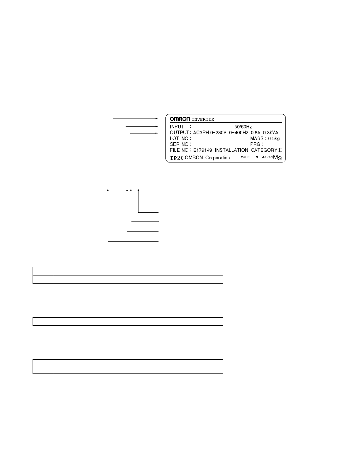
D Checking the Nameplate
Inverter model
Input specifications
Output specifications
D Checking the Model
3G3JV-A1001
Maximum applicable motor capacity
Voltage class
Installation type
Series name: 3G3JV Series
Maximum Applicable Motor Capacity
001 0.1 (0.1) kW
002 0.25/0.37 (0.2) kW
3G3JV-A1001
AC3PH 100-115V
3.2A
Note The figures in parentheses indicate capacities for motors used outside Japan.
Voltage Class
1 Single-phase 100-V AC input (100-V class)
Note The output is 3-phase 200 V AC.
Installation Type
A Panel-mounting models (IP10 min.) or
Closed wall mounting
D Checking for Damage
Check the overall appearance and check for damage or scratches resulting from transportation.
H Checking the Accessories
This manual is the only accessory provided with the 3G3JV. Set screws and other necessary parts must
be provided by the user.

Table of Contents
Chapter 1. Design 1-1. . . . . . . . . . . . . . . . . . . . . . . . . . . . . . . . . . . . . . . . . .
1-1 Installation 1-2. . . . . . . . . . . . . . . . . . . . . . . . . . . . . . . . . . . . . . . . . . . . . . . . . . . . . . . . . . . . . . . . .
1-1-1 Dimensions 1-2. . . . . . . . . . . . . . . . . . . . . . . . . . . . . . . . . . . . . . . . . . . . . . . . . . . . . . . . . .
1-1-2 Removing and Mounting the Covers 1-4. . . . . . . . . . . . . . . . . . . . . . . . . . . . . . . . . . . . . .
1-2 Wiring 1-6. . . . . . . . . . . . . . . . . . . . . . . . . . . . . . . . . . . . . . . . . . . . . . . . . . . . . . . . . . . . . . . . . . . .
1-2-1 Terminal Block 1-6. . . . . . . . . . . . . . . . . . . . . . . . . . . . . . . . . . . . . . . . . . . . . . . . . . . . . . .
1-2-2 Standard Connections 1-10. . . . . . . . . . . . . . . . . . . . . . . . . . . . . . . . . . . . . . . . . . . . . . . . . .
1-2-3 Wiring around the Main Circuit 1-11. . . . . . . . . . . . . . . . . . . . . . . . . . . . . . . . . . . . . . . . . .
1-2-4 Optional Accessories 1-12. . . . . . . . . . . . . . . . . . . . . . . . . . . . . . . . . . . . . . . . . . . . . . . . . .
1-3 Specifications 1-13. . . . . . . . . . . . . . . . . . . . . . . . . . . . . . . . . . . . . . . . . . . . . . . . . . . . . . . . . . . . . . .
Chapter 2. Preparing for Operation and Monitoring 2-1. . . . . . . . . . . . .
2-1 Using the Digital Operator 2-2. . . . . . . . . . . . . . . . . . . . . . . . . . . . . . . . . . . . . . . . . . . . . . . . . . . .
2-1-1 Nomenclature 2-2. . . . . . . . . . . . . . . . . . . . . . . . . . . . . . . . . . . . . . . . . . . . . . . . . . . . . . . .
2-1-2 Accepting Operation Commands While Changing Parameters 2-4. . . . . . . . . . . . . . . . . .
2-1-3 Outline of Operation 2-5. . . . . . . . . . . . . . . . . . . . . . . . . . . . . . . . . . . . . . . . . . . . . . . . . . .
2-2 Copying and Verifying Parameters 2-7. . . . . . . . . . . . . . . . . . . . . . . . . . . . . . . . . . . . . . . . . . . . . .
2-2-1 Parameters Used to Copy and Verify Parameters 2-7. . . . . . . . . . . . . . . . . . . . . . . . . . . . .
2-2-2 Outline of Copying Parameters 2-9. . . . . . . . . . . . . . . . . . . . . . . . . . . . . . . . . . . . . . . . . .
2-2-3 Procedures 2-10. . . . . . . . . . . . . . . . . . . . . . . . . . . . . . . . . . . . . . . . . . . . . . . . . . . . . . . . . . .
2-2-4 Error Messages for Copying and Verifying Parameters 2-12. . . . . . . . . . . . . . . . . . . . . . . .
Chapter 3. List of Parameters 3-1. . . . . . . . . . . . . . . . . . . . . . . . . . . . . . . .
Chapter 4. Maintenance Operations 4-1. . . . . . . . . . . . . . . . . . . . . . . . . . .
4-1 Protective and Diagnostic Functions 4-2. . . . . . . . . . . . . . . . . . . . . . . . . . . . . . . . . . . . . . . . . . . . .
4-1-1 Fault Detection (Fatal Error) 4-2. . . . . . . . . . . . . . . . . . . . . . . . . . . . . . . . . . . . . . . . . . . .
4-1-2 Warning Detection (Nonfatal Error) 4-7. . . . . . . . . . . . . . . . . . . . . . . . . . . . . . . . . . . . . . .
4-2 Inspection and Maintenance 4-10. . . . . . . . . . . . . . . . . . . . . . . . . . . . . . . . . . . . . . . . . . . . . . . . . . .

Design
1-1 Installation
1-2 Wiring
1-3 Specifications
1
Chapter 1
Design Chapter 1
1-1 Installation
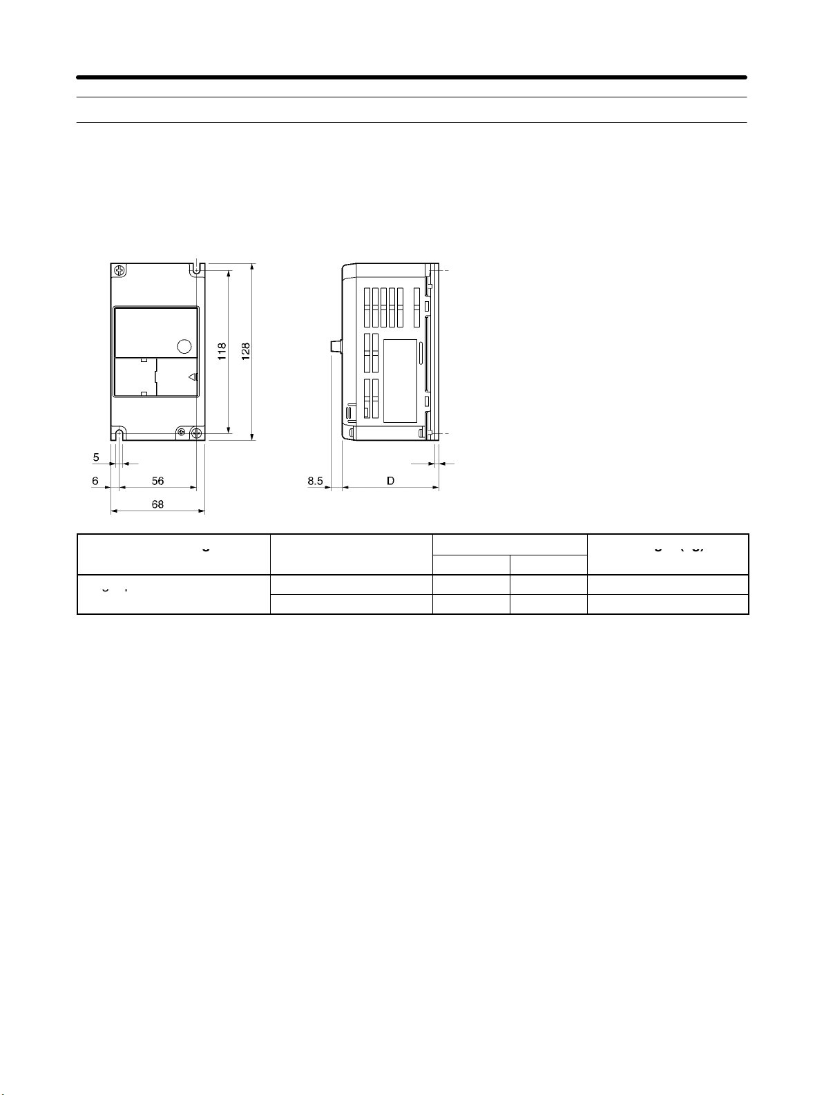
1-1-1 Dimensions
D 3G3JV-A1001, -A1002 (0.1 to 0.2 kW) Single-phase 100-V AC Input
t
Rated voltage Model 3G3JV-
Single-phase 100 V AC
A1001 80 3 Approx. 0.5
A1002 112 5 Approx. 0.8
Dimensions (mm)
D t
Weight (kg)
H Installation Direction and Dimensions
• Install the Inverter under the following conditions.
Ambient temperature for operation (panel-mounting): –10°C to 50°C
Humidity: 95% or less (no condensation)
• Install the Inverter in a clean location free from oil mist and dust. Alternatively, install it in a totally enclosed panel that is completely protected from floating dust.
• When installing or operating the Inverter, always take special care so that metal powder, oil, water, or
other foreign matter does not get into the Inverter.
• Do not install the Inverter on inflammable material such as wood.
H Direction
• Install the Inverter on a vertical surface so that the characters on the nameplate are oriented upward.
1-2
Design Chapter 1
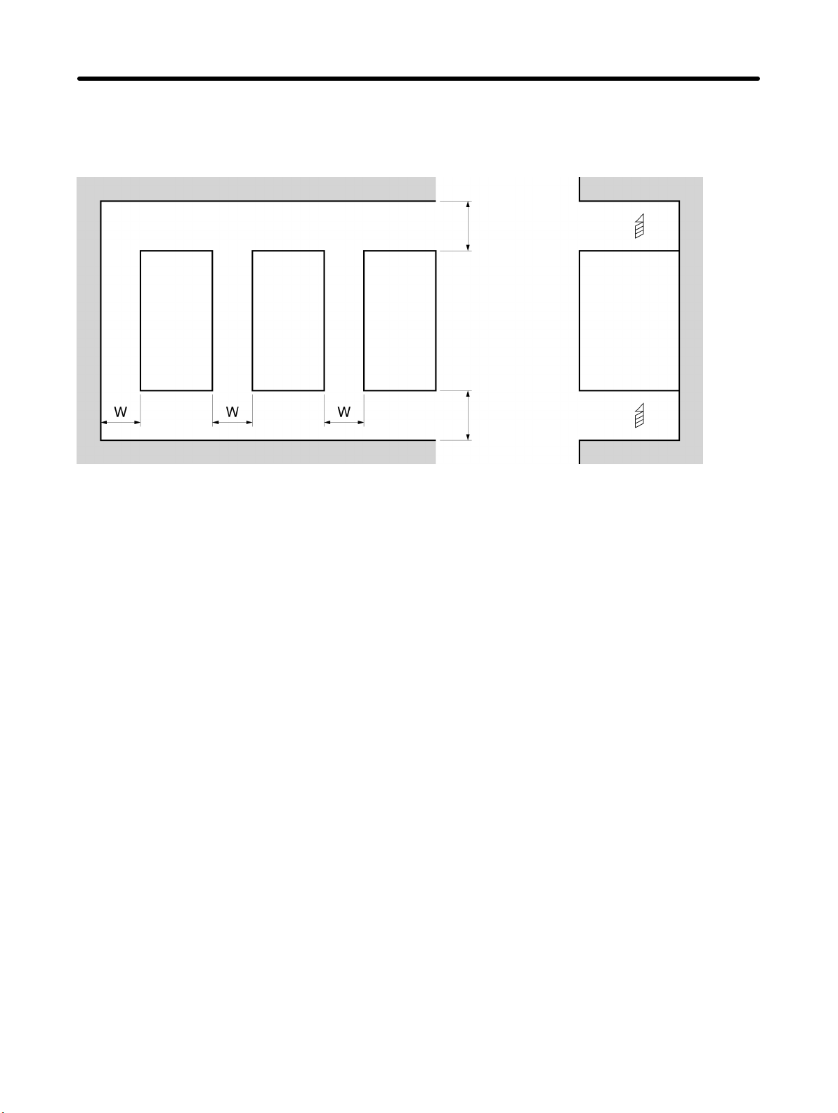
H Dimensions
• When installing the Inverter, always provide the following clearances to allow normal heat dissipation
from the Inverter.
W = 30 mm min.
Inverter
100 mm min. Air
SideInverter Inverter
100 mm min. Air
H Ambient Temperature Control
• To enhance operation reliability, the Inverter should be installed in an environment free from extreme
temperature changes.
• If the Inverter is installed in an enclosed environment such as a box, use a cooling fan or air conditioner
to maintain the internal air temperature below 50°C.
The life of the built-in electrolytic capacitors of the Inverter is prolonged by maintaining the internal air
temperature as low as possible.
• The surface temperature of the Inverter may rise approximately 30°C higher than the ambient temperature. Be sure to keep away equipment and wires from the Inverter as far as possible if the equipment
and wires are easily influenced by heat.
H Protecting Inverter from Foreign Matter during Installation
• Place a cover over the Inverter during installation to shield it from metal power produced by drilling.
Upon completion of installation, always remove the cover from the Inverter. Otherwise, ventilation will
be affected, causing the Inverter to overheat.
1-3
Design Chapter 1
1-1-2 Removing and Mounting the Covers
It is necessary to remove the front cover, optional cover, top protection cover, and the
bottom protection cover from the Inverter to wire the terminal block.
Follow the instructions below to remove the covers from the Inverter.
To mount the covers, take the opposite steps.
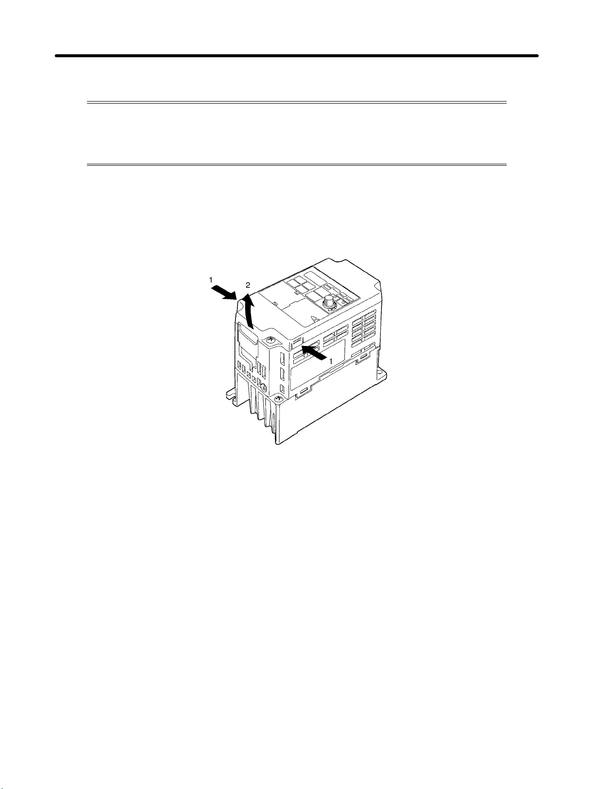
H Removing the Front Cover
• Loosen the front cover mounting screws with a screwdriver.
• Press the left and right sides of the front cover in the arrow 1 directions and lift the bottom of the cover in
the arrow 2 direction to remove the front cover as shown in the following illustration.
H Removing the Top and Bottom Protection Covers and Optional Cover
D Removing the Top and Bottom Protection Covers
• After removing the front cover, pull the top and bottom protection covers in the arrow 1 directions.
1-4

Design Chapter 1
D Removing the Optional Cover
• After removing the front cover, lift the optional cover in the arrow 2 direction based on position A as a
fulcrum.
Note The front cover functions as a terminal cover. The Digital Operator cannot be removed.
1-5
Design Chapter 1
1-2 Wiring
1-2-1 Terminal Block
Before wiring the terminal block, be sure to remove the front cover, top protection cover,
and the bottom protection cover.
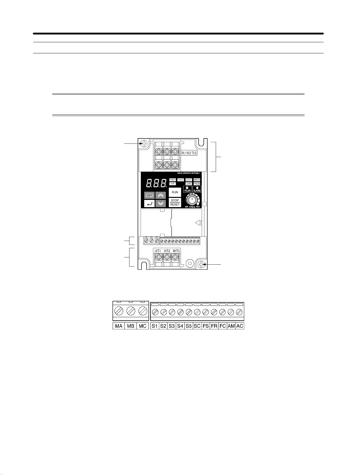
H Position of Terminal Block
Ground terminal
Main circuit input terminals
Control circuit terminals
Main circuit output terminals
H Arrangement of Control Circuit Terminals
Ground terminal
1-6
3G3JV A1j: 3 phase 200 to 230 V AC
Design Chapter 1
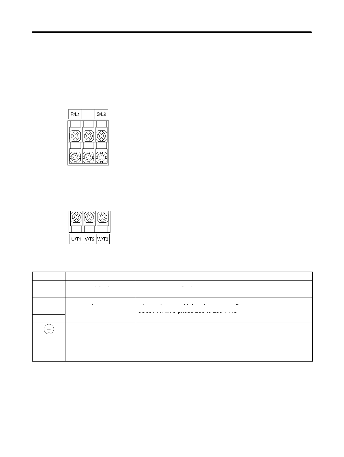
H Arrangement of Main Circuit Terminals
D 3G3JV-A1001, -A1002
Main Circuit Input Terminals
(Upper Side)
Main Circuit Output Terminals
(Lower Side)
H Main Circuit Terminals
Symbol Name Description
R/L1
S/L2
U/T1
V/T2
W/T3
Power supply input
terminals
Motor output terminals 3-phase power supply output for driving motors.
Ground terminal Be sure to ground the terminal under the following conditions.
Note The maximum output voltage corresponds to the power supply input voltage of the Inverter.
3G3JV-A1j: Single-phase 100 to 115 V AC
Note Connect single-phase input to terminals R/L1 and S/L2.
3G3JV-A1j: 3-phase 200 to 230 V AC
3G3JV-A1j: Ground at a resistance of 100 Ω or less, and connect
to the power supply’s neutral phase to conform to EC Directives.
Note Be sure to connect the ground terminal directly to the
motor frame ground.
1-7
Design Chapter 1
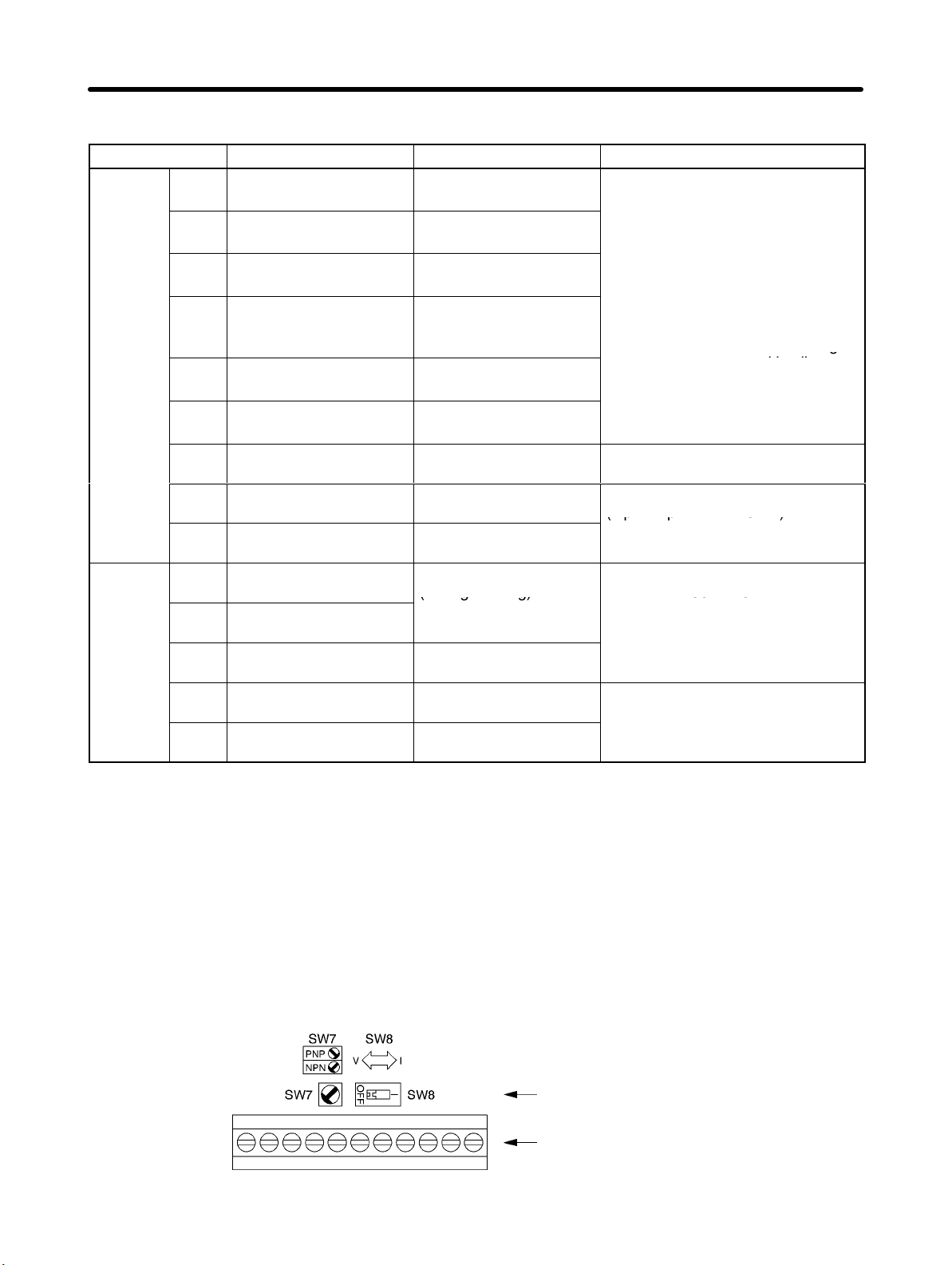
H Control Circuit Terminals
Symbol Name Function Signal level
Input
Output
S1 Forward/Stop Forward at ON. Stops at
OFF.
S2 Multi-function input 1
(S2)
S3 Multi-function input 2
(S3)
S4 Multi-function input 3
(S4)
S5 Multi-function input 4
(S5)
SC Sequence input com-
mon
FS Frequency reference
power supply
FR Frequency reference in-
put
FC Frequency reference
common
MA Multi-function contact
output (Normally open)
MB Multi-function contact
output (Normally closed)
MC Multi-function contact
output common
AM Analog monitor output Set by parameter n44
AC Analog monitor output
common
Set by parameter n36
(Reverse/Stop)
Set by parameter n37
(Fault reset)
Set by parameter n38
(External fault: Normally
open)
Set by parameter n39
(Multi-step reference 1)
Common for S1 through
S5
DC power supply for frequency reference use
Input terminal for frequency reference use
Common for frequency
reference use
Set by parameter n40
(during running)
Common for MA and
MB use
(Output frequency)
Common for AM use
Photocoupler
8 mA at 24 V DC
Note NPN is the default setting
for these terminals. Wire
them by providing a
common ground. No
required. To provide an
external power supply and
wire the terminals through
a common positive line,
however, set the SW7 to
and make sure tha
the power supply is at
24 V DC ±10%.
20 mA at 12 V DC
0 to 10 V DC
(input impedance: 20 kΩ)
Relay output
1 A max. at 30 V DC
1 A max. at 250 V AC
2 mA max. at 0 to 10 V DC
Note 1. Depending on the parameter settings, various functions can be selected for multi-function in-
puts and multi-function contacts outputs.
Note 2. Functions in parentheses are default settings.
H Selecting Input Method
• Switches SW7 and SW8, both of which are located above the control circuit terminals, are used for
input method selection.
Remove the front cover and optional cover to use these switches.
1-8
Selector
Control circuit terminal
block
Loading…
-
Page 1
Cat. No. I011-E1-3 USER’S MANUAL SYSDRIVE 3G3EV (Standard Models) Compact Low-noise Inverter… -
Page 2
Thank you for choosing this SYSDRIVE 3G3EV-series product. Proper use and handling of the product will ensure proper product performance, will length product life, and may prevent possible accidents. Please read this manual thoroughly and handle and operate the product with care. -
Page 3: Table Of Contents
Table of Contents Chapter 1. Getting Started ……Items to be Checked when Unpacking ……Precautions .
-
Page 4
Table of Contents Chapter 5. Operation ……Protective and Diagnostic Functions . -
Page 5: Chapter 1. Getting Started
Chapter 1 Getting Started 1-1 Items to be Checked when Unpacking 1-2 Precautions…
-
Page 6: Items To Be Checked When Unpacking
1-1 Items to be Checked when Unpacking H Checking the Product On delivery, always check that the delivered product is the SYSDRIVE 3G3EV Inverter that you ordered. Should you find any problems with the product, immediately contact your nearest local sales representative.
-
Page 7: Precautions
Chapter 1 Getting Started Voltage Class Special Specification Three-phase 200-VAC input English Models Single/Three-phase 200-VAC -CUE UL/CUL and EC Directives input Models Blank Japanese Models Installation Type/Option Panel mounting Option D Checking for Damage Check the overall appearance and check for damage or scratches resulting from trans- portation.
-
Page 8
Chapter 1 Getting Started If an inspection or some other task is to be performed, always wait at least one minute from the time all indicators on the front panel go off. (Note that this warning is applicable whenever you perform any task after turning the main circuit off.) H Do Not Remove the Digital Operator When the Main Circuit is Still On. -
Page 9: Chapter 2. Overview
Chapter 2 Overview 2-1 Features 2-2 Component Names…
-
Page 10: Features
Chapter 2 Overview 2-1 Features H Easy to Use D Basic Constants Displayed On Indicators Constants for basic operations such as frequency setting and acceleration/deceleration time setting are displayed on dedicated indicators. Therefore, constant numbers can be confirmed easily. D Minimum Constant Setting Items Constant setting items have been minimized to enable even first-time users to set constants easily.
-
Page 11
Chapter 2 Overview H Easy to Wire D Easy Wiring without Having to Open the Front Cover This Inverter can be wired just by opening the terminal block cover. D Separate Input and Output Terminal Blocks Power input terminals are located in the upper section, while motor output terminals are in the lower section. -
Page 12: Component Names
Chapter 2 Overview 2-2 Component Names H Main Unit Main Circuit Terminals (Input) Power input Braking resistor terminals connection terminals L1 N/L2 L3 Run indicator Digital Operator Alarm indicator Control circuit terminals Control circuit (output) terminals (input) SF SR S1 SC FS FR FC Ground terminal Motor output terminals…
-
Page 13: Digital Operator
Chapter 2 Overview H Digital Operator Data display section Monitor item indicators In-service item indicators (green indicators) Display These items can be monitored or set even section during operation. Stopped item indicators (red indicators) These items can be set only when the Inverter is stopped.
-
Page 14: Chapter 3. Design
Chapter 3 Design 3-1 Installation 3-2 Wiring…
-
Page 15: Installation
Chapter 3 Design 3-1 Installation 3-1-1 Outside/Mounting Dimensions Note All dimensions are in millimeters. H 3G3EV-A2001(-j) to 3G3EV-A2004(-j) (0.1 to 0.4 kW): Three-phase 200-VAC Input H 3G3EV-AB001(-j) to 3G3EV-AB002(-j) (0.1 to 0.2 kW): Single/Three-phase 200-VAC Input 4.5 dia. Note 1. For the 3G3EV-A2001(-j), 3G3EV-A2002(-j), and 3G3EV-AB001(-j), a U- shaped notch (4.5 mm wide) is provided instead of the upper mounting hole (4.5 mm in diameter).
-
Page 16
Chapter 3 Design D Three-phase 200-VAC Input Model 3G3EV Output Weight model (kg) A2001(-j) 0.1 kW Approx. A2002(-j) 0.2 kW Approx. A2004(-j) 0.4 kW Approx. D Single/Three-phase 200-VAC Input Model 3G3EV Output Weight model (kg) AB001(-j) 0.1 kW Approx. AB002(-j) 0.2 kW Approx. -
Page 17: Installation Conditions
Chapter 3 Design Note Install the Inverter with four M4 bolts. D Three-phase 200-VAC Input Model 3G3EV Output Weight (kg) model A2007(-j) 0.75 kW Approx. 1.3 A2015(-j) 1.5 kW Approx. 1.5 D Single/Three-phase 200-VAC Input Model 3G3EV Output Weight model (kg) 0.4 kW Approx.
-
Page 18
Chapter 3 Design •Install the Inverter in a clean location free from oil mist and dust. Alternatively, install it in a totally enclosed panel that is completely shielded from suspended dust. •When installing or operating the Inverter, always take special care so that metal pow- der, oil, water, or other foreign matter do not get in the Inverter. -
Page 19: Wiring
Chapter 3 Design 3-2 Wiring 3-2-1 Terminal Blocks H Name of Each Terminal Block Main Circuit Terminals (Input) Power input Braking resistor terminals connection terminals Control circuit terminals (output) Control circuit terminals (input) SF SR S1 SC FS FR FC Ground Main circuit terminals terminal…
-
Page 20: Main Circuit Terminals
Chapter 3 Design H Main Circuit Terminals D Input Terminals (Top Section) Terminal Name and description symbol R (L1) Power input terminals A2j: Three-phase 200 to 230 VAC, 50/60 Hz A2j: Three-phase 200 to 230 VAC, 50/60 Hz S (L2/N) ABj: Single-phase 200 to 240 VAC, 50/60 Hz Three-phase 200 to 230 VAC, 50/60 Hz A4j: Three-phase 380 to 460 VAC, 50/60 Hz…
-
Page 21: Control Circuit Terminals
Chapter 3 Design H Control Circuit Terminals D Input Terminals (On Right-hand Side) No external power supply is required because a built-in power supply is provided. Terminal Name and description Interface symbol Forward/Stop When the terminal is ON, the motor rotates in the forward direction.
-
Page 22: Standard Connection Diagram
Chapter 3 Design D Output Terminals (On Left-hand Side) Terminal Name and description Interface symbol Multi-function contact output (contact a) (see note) Multi-function contact output (contact b) 30 VDC (see note) 250 VAC Multi-function contact output (common) Note Constant No. 09 (n09) is used to set the function. This constant is factory set to “operation in progress.”…
-
Page 23: Wiring Around The Main Circuit
Chapter 3 Design Note 1. If a 3G3EV-ABjjj is used in single-phase input mode, single-phase 200 to 240 VAC power with a frequency of 50/60 Hz must be input between terminals R and S. Note 2. For the 3-wire sequence, refer to the wiring on page 4-12. Note 3.
-
Page 24
Chapter 3 Design Determining the Wire Size Determine the wire size for the main circuit so that line voltage drop is within 2% of the rated voltage. Line voltage drop V is calculated as follows: –3 (V) = 3 x wire resistance (Ω/km) x wire length (m) x amperage (A) x 10 H Wiring on the Input Side of Main Circuit D Installing a Molded-case Circuit Breaker Always connect the power input terminals (R, S, and T) and power supply via a molded-… -
Page 25
Chapter 3 Design D Installing an AC Reactor If the Inverter is connected to a large-capacity power transformer (600 kW or more) or the phase advance capacitor is switched, an excessive peak current may flow through the input power circuit, causing the converter unit to break down. To prevent this, install an optional AC reactor on the input side of the Inverter. -
Page 26
Chapter 3 Design D Installing a Noise Filter on the Power Supply Side Install a noise filter to eliminate noise transmitted between the power line and the Inverter. Wiring Example 1 Power 3G3IV-PHF 3G3EV supply Noise filter SYSMAC, etc. Other controllers Note Use a special-purpose noise filter for Inverters. -
Page 27
Chapter 3 Design D Never Connect Power Supply to Output Terminals Caution Never connect a power supply to output terminals U, V, and W. If voltage is applied to the output terminals, the internal mechanism of the Inverter will be damaged. D Never Short or Ground the Output Terminals Caution If the output terminals are touched with bare hands or the output wires come into contact with the Inverter casing, an electric shock or grounding will occur. -
Page 28
Chapter 3 Design Induction Noise: Electromagnetic induction generates noise on the signal line, causing the controller to malfunction. Radio Noise: Electromagnetic waves from the Inverter and cables cause the broadcasting radio receiver to make noise. D How to Prevent Induction Noise As described above, a noise filter can be used to prevent induction noise from being generated on the output side. -
Page 29: Ground Wiring
Chapter 3 Design D Cable Length between Inverter and Motor If the cable between the Inverter and the motor is long, the high-frequency leakage cur- rent will increase, causing the Inverter output current to increase as well. This may affect peripheral devices.
-
Page 30: Wiring Control Circuit Terminals
Chapter 3 Design 3-2-3 Wiring Control Circuit Terminals The control signal line must be 50 m or less and must be separated from the power line. If frequency references are input externally, use a twisted- pair shielded line. H Wiring Sequence Input/Output Terminals Wire the sequence input terminals (SF, SR, S1, and SC) and the multi-function contact output terminals (MA, MB, and MC) as described below.
-
Page 31
Chapter 3 Design D Wires to be Used Always use twisted-pair shielded wires to prevent malfunctions due to noise. Wire type Wire size Wire to be used Single wire 0.5 to 1.25 mm Polyethylene-insulated cable for instrumentation (with shield) Stranded wire 0.5 to 1.25 mm D Wiring Method •The wiring procedure is the same as for sequence input/output terminals, described… -
Page 32: Chapter 4. Preparing For Operation
Chapter 4 Preparing for Operation 4-1 Preparation Procedure 4-2 Using the Digital Operator 4-3 Test Run…
-
Page 33: Preparation Procedure
Chapter 4 Preparing for Operation 4-1 Preparation Procedure 1. Installation: Install the Inverter according to installation conditions. Refer to page 3-2 Check that all the installation conditions are met. 2. Wiring: Connect the Inverter to power supply and peripheral devices. Refer to page 3-6 Select peripheral devices that meet the specifications, and wire them correctly.
-
Page 34: Using The Digital Operator
Chapter 4 Preparing for Operation 6. Test Run: Perform a no-load test run and an actual loading test run to check that the motor and peripheral devices operate normally. Refer to page 4-25 Check the direction of motor rotation and check that the limit switches operate nor- mally.
-
Page 35
Chapter 4 Preparing for Operation H Function of Each Component D Display Sections Data display section Reference frequency values, output frequency values, output current values, constant settings, and error codes are displayed. Monitor item indicators When this indicator is lit, an output frequency value (Hz) is displayed in the data display section. -
Page 36: Outline Of Operation
Chapter 4 Preparing for Operation 4-2-2 Outline of Operation H Switching Data Display during Operation Press the Mode Key to switch data display. During operation, only the items in the in-service item indicators section can be monitored and the constants for these items can be set. If the power is turned off when the FOUT or IOUT indicator is lit, the same indicator lights up next time the power is turned on.
-
Page 37
Chapter 4 Preparing for Operation H Switching Data Display when Inverter is Stopped Press the Mode Key to switch data display. When the Inverter is stopped, all items can be monitored and the constant for each item can be set. Example Indi- Description… -
Page 38
Chapter 4 Preparing for Operation H Monitor Display The 3G3EV allows the user to monitor the reference frequency, output fre- quency, output current, and the direction of rotation. D Operation Method Indicator Example of Description operation data display 60.0 Press the Mode Key until the FREF indicator lights up. -
Page 39: Setting Constants
Chapter 4 Preparing for Operation 4-2-3 Setting Constants The 3G3EV (Standard Model) allows the user to set 18 different constants. The constants for basic operations are allocated to dedicated indicators, so the user need not refer to the constant nos. The constants allocated to dedicated indicators can be also set by lighting the PRGM indicator.
-
Page 40
Chapter 4 Preparing for Operation D Setting Constants Using the PRGM Indicator Example: Changing the value of constant no. 02 (operation mode selection) to “2.” Indicator Example of Explanation operation data display Press the Mode Key until the PRGM indicator lights up. -
Page 41
Chapter 4 Preparing for Operation H List of Constants Constant Dedicated Description Setting range Factory setting indicator Constant write-inhibit selec- 0, 1, 8, 9 tion/constant initialization Operation mode selection 0 to 5 Interruption mode selection 0, 1 Forward/reverse rotation For, rEv selection Multi-function input selec- 0 to 4… -
Page 42
Chapter 4 Preparing for Operation Note 3. The setting range for the 400-VAC models is “1 to 5.” Note 4. The factory setting for the 3G3EV-A4015-CUE is “3.” Note 5. Displaying the constant no. corresponding to an indicator in the “Dedicated indicator”… -
Page 43
Chapter 4 Preparing for Operation Example of 3-wire Sequence Mode Stop switch switch (contact b) (contact a) Run command (starts Inverter when “closed”) Stop command (stops Inverter when “opened”) Forward/Reverse rotation command (rotates motor in forward direction when “opened”; rotates motor in reverse direction when “closed”) Common Example of Operation Forward rotation… -
Page 44
Chapter 4 Preparing for Operation Note 2. The DIP switch is located inside the Inverter. Use this switch to change the set- ting when frequency references are to be input in terms of amperage (4 to 20 mA). For details, refer to Section 7-2 Frequency Reference by Amperage Input. For voltage input, never set the DIP switch to ON. -
Page 45
Chapter 4 Preparing for Operation Forward/Reverse Rotation Selection f%r , reU Factory setting f%r Setting range (forward rota- tion) This constant is used to specify the direction of motor rotation when the Inverter is oper- ated with the Digital Operator. Value Description Forward rotation… -
Page 46
Chapter 4 Preparing for Operation Note MA is turned on when the difference between the reference frequency and the output frequency falls within 2 Hz. MA is turned off when the difference exceeds ±4 Hz. Example of Operation Reference frequency Detection range ±2 Hz Release range… -
Page 47
Chapter 4 Preparing for Operation Frequency Reference 1 Setting range 0.0 to 400 (Hz) Factory setting 6.0 (Hz) Frequency Reference 2 Setting range 0.0 to 400 (Hz) Factory setting 0.0 (Hz) •These constants are used to set reference frequency values. •The unit of setting is as follows: 0.0 to 99.9 (Hz): 0.1 (Hz) 100 to 400 (Hz): 1 (Hz) -
Page 48
Chapter 4 Preparing for Operation Acceleration Time Setting range 0.0 to 999 Factory setting 10.0 (seconds) (seconds) Deceleration time Setting range 0.0 to 999 Factory setting 10.0 (seconds) (seconds) •These constants are used to set acceleration time (required to increase the output fre- quency from the stopped state to the maximum frequency) and deceleration time (re- quired to decrease the output frequency from the maximum frequency to the stopped state). -
Page 49
Chapter 4 Preparing for Operation Maximum Frequency Setting range 50.0 to 400 Factory setting 60.0 (Hz) (Hz) Unit of setting 50.0 to 99.9 (Hz) : 0.1 (Hz) 100 to 400 (Hz) : 1 (Hz) Maximum Voltage Setting range 1 to 255 (510) Factory setting 200 (400) (V) Unit of setting 1 (V) Maximum Voltage Frequency (Basic Frequency) -
Page 50
Chapter 4 Preparing for Operation Electronic Thermal Reference Current Setting range 0.0 to Factory setting See note 2 (see note 1) (A) Unit of setting 0.1 (A) •This constant is used to set an electronic thermal reference value to protect the motor from overheating. -
Page 51
Chapter 4 Preparing for Operation Operation after Recovery from Power Interruption Setting range 0, 1, 2 Factory setting 0 This constant is used to select the processing to be performed after recovery from an instantaneous power interruption. Value Description Discontinues operation. Continues operation only if power interruption is within 0.5 second. -
Page 52
Chapter 4 Preparing for Operation Note 2. The factory setting for the 3G3EV-A4015-CUE is “3.” Note 3. With the 400-VAC class, the continuous output current cannot be used to 100% of the rated value if the constant is set to “5” for Inverters of 0.75 kW or less or if it is set to “4”… -
Page 53
Chapter 4 Preparing for Operation Frequency Reference Gain Setting range 0.10 to 2.55 Factory setting 1.00 (times) (times) Unit of setting 0.01 (times) Frequency Reference Bias Setting range –99 to 99 (%) Factory setting 0 (%) Unit of setting 1 (%) •These constants are used to set the relationship between analog voltage and refer- ence frequencies when frequency references are input through control terminals FR and FC. -
Page 54
Chapter 4 Preparing for Operation Stop Key Selection Setting range 0, 1 Factory setting 0 •When inputting Inverter operation from the control terminals, the Stop Key on the Digi- tal Operator can be set to “enabled” or “disabled.” Value Description Stop Key enabled Stop Key disabled Note 1. -
Page 55
Chapter 4 Preparing for Operation •Recorded are Inverter errors and other errors that actuate a protective mechanism. Warning (automatically recovered error) is not recorded. •If no error has occurred, the indicator is not lit. •All error codes are listed below. Error code Description Error category… -
Page 56: Test Run
Chapter 4 Preparing for Operation 4-3 Test Run After wiring is complete, perform a test run of the Inverter as follows. First, start the motor through the Digital Operator without connecting the motor to the mechanical system. Next, connect the motor to the mechanical sys- tem and perform a test run.
-
Page 57: Setting Rated Motor Amperage
Chapter 4 Preparing for Operation 4-3-5 Setting Rated Motor Amperage •Set the rated motor amperage in constant no. 31 (electronic thermal reference current) or with the “THR” indicator lit. 4-3-6 Setting the Reference Frequency •Set the frequency corresponding to the motor speed in constant no. 11 (frequency ref- erence 1) or with the “FREF”…
-
Page 58: Chapter 5. Operation
Chapter 5 Operation 5-1 Protective and Diagnostic Functions 5-2 Troubleshooting 5-3 Maintenance and Inspection…
-
Page 59: Protective And Diagnostic Functions
Chapter 5 Operation 5-1 Protective and Diagnostic Functions The 3G3EV has excellent protective and diagnostic functions. The RUN and ALARM indicators on the front panel indicate the current Inverter sta- tus, and the data display section also displays information about an error that has occurred.
-
Page 60
Chapter 5 Operation H Data Display and Action to be Taken when Warning Status Arises The ALARM indicator flashes when warning status arises. The data display section also flashes. When warning status arises, no error code is output. Eliminating the cause recovers the system automatically. Data Description Action… -
Page 61
Chapter 5 Operation H Data Display and Action to be Taken when Protective Mechanism is Actuated The ALARM indicator lights up when the protective mechanism is actuated. In this event, Inverter output is shut off, and the motor coasts to a stop. Check the cause of the error, take the necessary action, and perform fault reset or turn the power off, then on. -
Page 62
Chapter 5 Operation Data Description Cause and action display • The input power voltage dropped. Main circuit undervoltage (UV1) • Open-phase occurred. The DC voltage of the main circuit dropped below the specified level. • An instantaneous power interruption 3G3EV-A2jjj: Approximately 200 V occurred. -
Page 63
Chapter 5 Operation Data Description Cause and action display • Review the load size, V/f characteris- Motor overload (OL1) tics, acceleration/deceleration time, The electronic thermal relay actuated and cycle time. the motor overload protection function. • Set the rated motor amperage in constant No. -
Page 64
Chapter 5 Operation H Data Display and Action to be Taken when Inverter Error Occurs The first character of an error code is always “F” when an Inverter error occurs. (Howev- er, all indicators are not lit when a control circuit error occurs.) If an Inverter error occurs, turn the power off, then on. -
Page 65: Troubleshooting
Chapter 5 Operation 5-2 Troubleshooting If the Inverter or motor does not operate properly when the system is started, constant settings or wiring may be incorrect. In this case, take the appropriate action as described below. (If an error code is displayed, refer to 5-1 Protective and Diagnostic Functions.) 5-2-1 Constants Fail to Set H err is Displayed in the Data Display Section.
-
Page 66: Motor Rotates In The Wrong Direction
Chapter 5 Operation •The reference frequency is too low. When the reference frequency is less than 1.5 Hz, the Inverter cannot operate. Change the reference frequency to 1.5 Hz or more. •The sequence input method is wrong. If the 3-wire sequence input mode is selected as an external terminal function instead of the actual 2-wire sequence input mode, the motor will not run, in which case change the constant or change to the sequence input that matches the constant setting.
-
Page 67: Motor Deceleration Is Too Slow
Chapter 5 Operation To reverse the direction of rotation, switch the wires of two phases of U, V, and W as shown below. Inverter Motor Forward rotation Reverse rotation 5-2-4 Motor Deceleration is Too Slow H Deceleration Time is Too Long Even if a Braking Resistor is Connected.
-
Page 68: Motor Burns
Chapter 5 Operation 5-2-6 Motor Burns •The dielectric strength of the motor is insufficient. Surge arises when the motor (inductive load) is connected to the output side of the Inverter. Normally, the maximum surge voltage is approximately three times the power voltage.
-
Page 69: Mechanical System Makes Noise
Chapter 5 Operation S Install an input noise filter. Install an input noise filter (3G3IV-PHF) on the power input side of the Inverter. S Install an output noise filter. Install an output noise filter (3G3IV-PLF) on the output side of the Inverter. S Use metal box and piping.
-
Page 70: Maintenance And Inspection
Chapter 5 Operation Under the wiring condition shown below, if the control output power supply is lower than 24 VDC or if it is set to OFF, current may flow in the direction shown by the arrows and may operate the Inverter input. In such a case, insert a diode in the A section shown below.
-
Page 71
Chapter 5 Operation H Regular Maintenance Check the items below during regular maintenance. Before starting inspection, always turn the power off, then wait at least one minute after all indicators on the front panel go off. Touching terminals immediately after turning the power off may cause an electrical shock. -
Page 72: Chapter 6. Specifications
Chapter 6 Specifications 6-1 Specifications of Main Unit…
-
Page 73
Chapter 6 Specifications 6-1 Specifications of Main Unit H Rating Model 3G3EV- A2001(-j) A2002(-j) A2004(-j) A2007(-j) A2015(-j) Three phase, Power Rated voltage Three-phase, 200 to 230 VAC, 50/60 Hz 200 VAC supply and frequency Allowable –15% to 10 % voltage fluctuation ±5% Allowable… -
Page 74: General Specifications
Chapter 6 Specifications Model 3G3EV- Three A4002(-j) A4004(-j) A4007(-j) A4015(-j) phase, Power Rated voltage Three-phase, 380 to 460 VAC, 50/60 Hz 400 VAC supply and frequency Allowable –15% to 10 % voltage fluctuation ±5% Allowable frequency fluctuation Heating value (W) 25.5 34.7 56.0…
-
Page 75
Chapter 6 Specifications H Control Characteristics Control method Sine-wave PWM method (automatic torque boost) Frequency control 1.5 to 400 Hz range Frequency accuracy Digital command: ±0.01% (–10°C to 50°C) (temperature fluctuation) Analog command: ±1% (25 ±10°C) Frequency setting Digital command: resolution 0.1 Hz (less than 100 Hz), 1 Hz (100 Hz or more) Analog command:… -
Page 76: Protection Functions
Chapter 6 Specifications H Protection Functions Motor protection Electronic thermal protection Instantaneous When 250% of the rated output amperage is exceeded overcurrent protection Overload protection When 150% of the rated output amperage is exceeded for one minute Overvoltage protection Stops the system when DC voltage of the main circuit exceeds approximately 410 V (400-VAC Class approximately 820 V) Voltage drop protection 3G3EV-A2jjj: Stops the system when voltage drops below approximately 200 V…
-
Page 77
Chapter 6 Specifications H Operation Specifications Three photocoupler input terminals (24 VDC, 8 mA) Control input • Forward/stop [SF] • Reverse/stop [SR] • Multi-function input [S1] (set in constant No. 06) Select either of “fault reset,” “external fault,” and “multi-step speed command.”… -
Page 78: Chapter 7. Appendix A
Chapter 7 Appendix A 7-1 Notes on Using Inverter for Motor 7-2 Frequency Reference by Amperage Input 7-3 List of Product Models…
-
Page 79: Notes On Using Inverter For Motor
Chapter 7 Appendix A 7-1 Notes on Using Inverter for Motor H Using Inverter for Existing Standard Motor When a standard motor is operated with this Inverter, a power loss is slightly higher than when operated with a commercial power supply. In addition, cooling effects also decline in the low-speed range, resulting in an increase in the motor temperature.
-
Page 80
Chapter 7 Appendix A D Vibration The 3G3EV series employs high carrier PWM control to reduce motor vibration. When the motor is operated with this Inverter, motor vibration is almost the same as when op- erated with a commercial power supply. However, motor vibration may become greater in the following cases: •Resonance with the natural frequency of mechanical system Take special care when a machine that has been operated at a constant speed is to… -
Page 81: Frequency Reference By Amperage Input
Chapter 7 Appendix A D Gearmotor The speed range for continuous operation differs according to the lubrication method and motor manufacturer. In particular, continuous operation of an oil-lubricated motor in the low speed range may result in burning. If the motor is to be operated at a speed high- er than 60 Hz, consult with the manufacturer.
-
Page 82
Chapter 7 Appendix A 3. Removing the Digital Operator S Insert a finger in the recessed section below the Digital Operator, then lift the under- neath of the Digital Operator. S When the connector comes off, grip the lower edges of the Digital Operator, and slide it down until it comes off. -
Page 83
Chapter 7 Appendix A “SW1” is marked near the switch. Switch indicator V: Voltage input I: Amperage input DIP switch 5. Changing the DIP switch setting To use amperage input mode, set this switch to ON by sliding it to the right. (factory setting) 6. -
Page 84: List Of Product Models
Chapter 7 Appendix A 7-3 List of Product Models H Inverter Specifications Model Standard Three-phase 200 VAC input 0.1 kW 3G3EV-A2001(-j) models 0.2 kW 3G3EV-A2002(-j) 0.4 kW 3G3EV-A2004(-j) 0.75 kW 3G3EV-A2007(-j) 1.5 kW 3G3EV-A2015(-j) Single/Three-phase 200 VAC input 0.1 kW 3G3EV-AB001(-j) 0.2 kW 3G3EV-AB002(-j)
-
Page 85: Output Noise Filter
Chapter 7 Appendix A H Braking Resistor (Duty Cycle 3% ED) Specifications Model 400 Ω 200-VAC class 0.1 kW/0.2 kW 3G3IV-PERF150WJ401 200 Ω 0.4 kW/0.75 kW 3G3IV-PERF150WJ201 100 Ω 1.5 kW 3G3IV-PERF150WJ101 750 Ω 400-VAC class 0.75 kW or less 3G3IV-PERF150WJ751 400 Ω…
-
Page 86
Chapter 7 Appendix A H DIN Track Specifications Model 3G3EV-A2001(-j) to 3G3EV-A2004(-j) 3G3EV-PSPAT3 3G3EV-AB001(-j) and 3G3EV-AB002(-j) 3G3EV-A2007(-j) to 3G3EV-A2015(-j) 3G3EV-PSPAT4 3G3EV-AB004(-j) and 3G3EV-AB007(-j) 3G3EV-A4002(-j) to 3G3EV-A4007(-j) -
Page 87
Chapter 7 Appendix A List of Constants Used with 3G3EV Standard Model Constant Indi- Description Setting range Setting cators Constant 0: Only n01 can be set. write-inhibit 1: All constants can be set. selection 8: Constant settings are initialized. /constant 9: Inverter is initialized in 3-wire initialization sequence mode. -
Page 88
Chapter 7 Appendix A Constant Indi- Description Setting range Setting cators Deceleration 0.0 to 999 (seconds) [10.0] time Maximum 50.0 to 400 (Hz) [60.0] frequency Maximum 1 to 255 (V) (see note 1) [200] voltage Maximum 1.6 to 400 (Hz) [60.0] voltage frequency (basic…
SETUP MANUAL
SYSDRIVE 3G3JV Compact Simplified Inverters
Cat. No. I546-E1-02 0675398-6B
Thank you for choosing this SYSDRIVE 3G3JV-series product. Proper use and handling of the product will ensure proper product performance, will lengthen product life, and may prevent possible accidents. Please read this manual thoroughly and handle and operate the product with care.
1. To ensure safe and proper use of the OMRON Inverters, please read this SETUP MANUAL and the USERS MANUAL (Cat. No. I528-E1) to gain sufficient knowledge of the devices, safety information, and precautions before actual use.
2. The products are illustrated without covers and shieldings for closer look in this SET- UP MANUAL and the USERS MANUAL. For actual use of the products, make sure to use the covers and shieldings as specified.
3. This SETUP MANUAL and other related users manuals are to be delivered to the ac- tual end users of the products.
4. Please keep this manual close at hand for future reference.
5. If the product has been left unused for a long time, please inquire at our sales repre- sentative.
NOTICE 1. This manual describes the functions of the product and relations with other
products. You should assume that anything not described in this manual is not possible.
2. Although care has been given in documenting the product, please contact your OMRON representative if you have any suggestions on improving this manual.
3. The product contains potentially dangerous parts under the cover. Do not attempt to open the cover under any circumstances. Doing so may result in injury or death and may damage the product. Never attempt to repair or disassemble the product.
4. We recommend that you add the following precautions to any instruction manuals you prepare for the system into which the product is being installed.
Precautions on the dangers of high-voltage equipment.
Precautions on touching the terminals of the product even after power has been turned OFF. (These terminals are live even with the power turned OFF.)
5. Specifications and functions may be changed without notice in order to improve product performance.
Items to Check Before Unpacking Check the following items before removing the product from the package:
Has the correct product been delivered (i.e., the correct model number and speci- fications)?
Has the product been damaged in shipping?
Are any screws or bolts loose?
!
!
!
Notice: OMRON products are manufactured for use according to proper procedures by a qualified operator and only for the purposes described in this manual.
The following conventions are used to indicate and classify precautions in this manual. Al- ways heed the information provided with them. Failure to heed precautions can result in inju- ry to people or damage to property.
DANGER Indicates an imminently hazardous situation which, if not avoided, will result in death or serious injury. Additionally, there may be severe property damage.
WARNING Indicates a potentially hazardous situation which, if not avoided, could result in death or serious injury. Additionally, there may be severe property damage.
Caution Indicates a potentially hazardous situation which, if not avoided, may result in minor or moderate injury, or property damage.
OMRON Product References All OMRON products are capitalized in this manual. The word Unit is also capitalized when it refers to an OMRON product, regardless of whether or not it appears in the proper name of the product.
The abbreviation Ch, which appears in some displays and on some OMRON products, often means word and is abbreviated Wd in documentation in this sense.
The abbreviation PC means Programmable Controller and is not used as an abbreviation for anything else.
Visual Aids The following headings appear in the left column of the manual to help you locate different types of information.
Note Indicates information of particular interest for efficient and convenient operation of the product.
OMRON, 2005 All rights reserved. No part of this publication may be reproduced, stored in a retrieval system, or transmitted, in any form, or by any means, mechanical, electronic, photocopying, recording, or otherwise, without the prior written permission of OMRON.
No patent liability is assumed with respect to the use of the information contained herein. Moreover, because OMRON is constantly striving to improve its high-quality products, the information contained in this manual is subject to change without notice. Every precaution has been taken in the preparation of this manual. Never- theless, OMRON assumes no responsibility for errors or omissions. Neither is any liability assumed for dam- ages resulting from the use of the information contained in this publication.
Read and Understand this Manual Please read and understand this manual before using the product. Please consult your OMRON representative if you have any questions or comments.
Warranty and Limitations of Liability
WARRANTY
OMRONs exclusive warranty is that the products are free from defects in materials and workmanship for a period of one year (or other period if specified) from date of sale by OMRON.
OMRON MAKES NO WARRANTY OR REPRESENTATION, EXPRESS OR IMPLIED, REGARDING NON-INFRINGEMENT, MERCHANTABILITY, OR FITNESS FOR PARTICULAR PURPOSE OF THE PRODUCTS. ANY BUYER OR USER ACKNOWLEDGES THAT THE BUYER OR USER ALONE HAS DETERMINED THAT THE PRODUCTS WILL SUITABLY MEET THE REQUIREMENTS OF THEIR INTENDED USE. OMRON DISCLAIMS ALL OTHER WARRANTIES, EXPRESS OR IMPLIED.
LIMITATIONS OF LIABILITY
OMRON SHALL NOT BE RESPONSIBLE FOR SPECIAL, INDIRECT, OR CONSEQUENTIAL DAMAGES, LOSS OF PROFITS OR COMMERCIAL LOSS IN ANY WAY CONNECTED WITH THE PRODUCTS, WHETHER SUCH CLAIM IS BASED ON CONTRACT, WARRANTY, NEGLIGENCE, OR STRICT LIABILITY.
In no event shall the responsibility of OMRON for any act exceed the individual price of the product on which liability is asserted.
IN NO EVENT SHALL OMRON BE RESPONSIBLE FOR WARRANTY, REPAIR, OR OTHER CLAIMS REGARDING THE PRODUCTS UNLESS OMRONS ANALYSIS CONFIRMS THAT THE PRODUCTS WERE PROPERLY HANDLED, STORED, INSTALLED, AND MAINTAINED AND NOT SUBJECT TO CONTAMINATION, ABUSE, MISUSE, OR INAPPROPRIATE MODIFICATION OR REPAIR.
Application Considerations
SUITABILITY FOR USE
OMRON shall not be responsible for conformity with any standards, codes, or regulations that apply to the combination of products in the customers application or use of the products.
At the customers request, OMRON will provide applicable third party certification documents identifying ratings and limitations of use that apply to the products. This information by itself is not sufficient for a complete determination of the suitability of the products in combination with the end product, machine, system, or other application or use.
The following are some examples of applications for which particular attention must be given. This is not intended to be an exhaustive list of all possible uses of the products, nor is it intended to imply that the uses listed may be suitable for the products:
Outdoor use, uses involving potential chemical contamination or electrical interference, or conditions or uses not described in this manual.
Nuclear energy control systems, combustion systems, railroad systems, aviation systems, medical equipment, amusement machines, vehicles, safety equipment, and installations subject to separate industry or government regulations.
Systems, machines, and equipment that could present a risk to life or property.
Please know and observe all prohibitions of use applicable to the products.
NEVER USE THE PRODUCTS FOR AN APPLICATION INVOLVING SERIOUS RISK TO LIFE OR PROPERTY WITHOUT ENSURING THAT THE SYSTEM AS A WHOLE HAS BEEN DESIGNED TO ADDRESS THE RISKS, AND THAT THE OMRON PRODUCTS ARE PROPERLY RATED AND INSTALLED FOR THE INTENDED USE WITHIN THE OVERALL EQUIPMENT OR SYSTEM.
PROGRAMMABLE PRODUCTS
OMRON shall not be responsible for the users programming of a programmable product, or any consequence thereof.
Disclaimers
CHANGE IN SPECIFICATIONS
Product specifications and accessories may be changed at any time based on improvements and other reasons.
It is our practice to change model numbers when published ratings or features are changed, or when significant construction changes are made. However, some specifications of the products may be changed without any notice. When in doubt, special model numbers may be assigned to fix or establish key specifications for your application on your request. Please consult with your OMRON representative at any time to confirm actual specifications of purchased products.
DIMENSIONS AND WEIGHTS
Dimensions and weights are nominal and are not to be used for manufacturing purposes, even when tolerances are shown.
PERFORMANCE DATA
Performance data given in this manual is provided as a guide for the user in determining suitability and does not constitute a warranty. It may represent the result of OMRONs test conditions, and the users must correlate it to actual application requirements. Actual performance is subject to the OMRON Warranty and Limitations of Liability.
ERRORS AND OMISSIONS
The information in this manual has been carefully checked and is believed to be accurate; however, no responsibility is assumed for clerical, typographical, or proofreading errors, or omissions.
!
!
!
!
!
!
!
!
!
General Precautions Observe the following precautions when using the SYSDRIVE Inverters and peripheral de- vices. This manual may include illustrations of the product with protective covers removed in order to describe the components of the product in detail. Make sure that these protective covers are on the product before use. Consult your OMRON representative when using the product after a long period of storage.
WARNING Do not touch the inside of the Inverter. Doing so may result in electrical shock.
WARNING Operation, maintenance, or inspection must be performed after turning OFF the power supply, confirming that the CHARGE indicator (or status indicators) are OFF, and after waiting for the time specified on the front cover. Not doing so may result in electrical shock.
WARNING Do not damage, pull on, apply stress to, place heavy objects on, or pinch the cables. Doing so may result in electrical shock.
WARNING Do not touch the rotating parts of the motor under operation. Doing so may result in injury.
WARNING Do not modify the product. Doing so may result in injury or damage to the product.
Caution Do not store, install, or operate the product in the following places. Doing so may result in electrical shock, fire or damage to the product.
Locations subject to direct sunlight. Locations subject to temperatures or humidity outside the range specified in the
specifications. Locations subject to condensation as the result of severe changes in temperature. Locations subject to corrosive or flammable gases. Locations subject to exposure to combustibles. Locations subject to dust (especially iron dust) or salts. Locations subject to exposure to water, oil, or chemicals. Locations subject to shock or vibration.
Caution Do not touch the Inverter radiator, regenerative resistor, or Servomotor while the power is being supplied or soon after the power is turned OFF. Doing so may result in a skin burn due to the hot surface.
Caution Do not conduct a dielectric strength test on any part of the Inverter. Doing so may result in damage to the product or malfunction.
Caution Take appropriate and sufficient countermeasures when installing systems in the fol- lowing locations. Not doing so may result in equipment damage.
Locations subject to static electricity or other forms of noise. Locations subject to strong electromagnetic fields and magnetic fields. Locations subject to possible exposure to radioactivity. Locations close to power supplies.
!
!
!
!
!
!
!
!
!
!
!
!
Transportation Precautions Caution Do not hold by front cover or panel, instead, hold by the radiation fin (heat sink) while
transporting the product. Doing so may result in injury.
Caution Do not pull on the cables. Doing so may result in damage to the product or malfunc- tion.
Caution Use the eye-bolts only for transporting the Inverter. Using them for transporting the machinery may result in injury or malfunction.
Installation Precautions WARNING Provide an appropriate stopping device on the machine side to secure safety. (A
holding brake is not a stopping device for securing safety.) Not doing so may result in injury.
WARNING Provide an external emergency stopping device that allows an instantaneous stop of operation and power interruption. Not doing so may result in injury.
Caution Be sure to install the product in the correct direction and provide specified clear- ances between the Inverter and control panel or with other devices. Not doing so may result in fire or malfunction.
Caution Do not allow foreign objects to enter inside the product. Doing so may result in fire or malfunction.
Caution Do not apply any strong impact. Doing so may result in damage to the product or malfunction.
Wiring Precautions WARNING Wiring must be performed only after confirming that the power supply has been
turned OFF. Not doing so may result in electrical shock.
WARNING Wiring must be performed by authorized personnel. Not doing so may result in electrical shock or fire.
WARNING Be sure to confirm operation only after wiring the emergency stop circuit. Not doing so may result in injury.
WARNING Always connect the ground terminals to a ground of 100 or less. Not connecting to a proper ground may result in electrical shock.
!
!
!
!
!
!
!
!
!
!
!
!
!
Caution Install external breakers and take other safety measures against short-circuiting in external wiring. Not doing so may result in fire.
Caution Confirm that the rated input voltage of the Inverter is the same as the AC power sup- ply voltage. An incorrect power supply may result in fire, injury, or malfunction.
Caution Connect the Braking Resistor and Braking Resistor Unit as specified in the manual. Not doing so may result in fire.
Caution Be sure to wire correctly and securely. Not doing so may result in injury or damage to the product.
Caution Be sure to firmly tighten the screws on the terminal block. Not doing so may result in fire, injury, or damage to the product.
Caution Do not connect an AC power to the U, V, or W output. Doing so may result in damage to the product or malfunction.
Caution Set the multi-function contact input parameter for NC contact terminals (e.g., 3-wire sequence) before wiring them. If the parameters default setting is used, the motor may start running when the input terminal S2 is turned ON.
Operation and Adjustment Precautions WARNING Turn ON the input power supply only after mounting the front cover, terminal covers,
bottom cover, Operator, and optional items. Not doing so may result in electrical shock.
WARNING Do not remove the front cover, terminal covers, bottom cover, Operator, or optional items while the power is being supplied. Doing so may result in electrical shock or damage to the product.
WARNING Do not operate the Operator or switches with wet hands. Doing so may result in electrical shock.
WARNING Do not touch the inside of the Inverter. Doing so may result in electrical shock.
WARNING Do not come close to the machine when using the error retry function because the machine may abruptly start when stopped by an alarm. Doing so may result in injury.
WARNING Do not come close to the machine immediately after resetting momentary power interruption to avoid an unexpected restart (if operation is set to be continued in the processing selection function after momentary power interruption is reset). Doing so may result in injury.
!
!
!
!
!
!
!
!
!
!
!
!
WARNING Provide a separate emergency stop switch because the STOP Key on the Operator is valid only when function settings are performed. Not doing so may result in injury.
WARNING Be sure to confirm that the RUN signal is turned OFF before turning ON the power supply, resetting the alarm, or switching the LOCAL/REMOTE selector. Doing so while the RUN signal is turned ON may result in injury.
Caution Be sure to confirm permissible ranges of motors and machines before operation be- cause the Inverter speed can be easily changed from low to high. Not doing so may result in damage to the product.
Caution Provide a separate holding brake when necessary. Not doing so may result in injury.
Caution Do not perform a signal check during operation. Doing so may result in injury or dam- age to the product.
Caution Do not carelessly change settings. Doing so may result in injury or damage to the product.
Maintenance and Inspection Precautions WARNING Do not touch the Inverter terminals while the power is being supplied.
WARNING Maintenance or inspection must be performed only after turning OFF the power supply, confirming that the CHARGE indicator (or status indicators) is turned OFF, and after waiting for the time specified on the front cover. Not doing so may result in electrical shock.
WARNING Maintenance, inspection, or parts replacement must be performed by authorized personnel. Not doing so may result in electrical shock or injury.
WARNING Do not attempt to take the Unit apart or repair. Doing either of these may result in electrical shock or injury.
Caution Carefully handle the Inverter because it uses semiconductor elements. Careless handling may result in malfunction.
Caution Do not change wiring, disconnect connectors, the Operator, or optional items, or re- place fans while power is being supplied. Doing so may result in injury, damage to the product, or malfunction.
Warnings for UL/cUL Marking Do not connect or disconnect wiring, or perform signal checks while the power supply is turned ON.
The Inverter internal capacitor is still charged even after the power supply is turned OFF. To prevent electrical shock, disconnect all power before servicing the Inverter. Then wait at least one minute after the power supply is disconnected and all indicators are OFF.
Do not perform a withstand voltage test on any part of the Inverter. This electronic equipment uses semiconductors and is vulnerable to high voltage.
Do not remove the Digital Operator or the blank cover unless the power supply is turned OFF. Never touch the printed control board (PCB) while the power supply is turned ON.
The Inverter is not suitable for use on a circuit capable of delivering more than 5,000 RMS symmetrical amperes, 250 volts maximum (100-V-class Units).
Take measures against overcurrent, overload, and overheating by using the Motor Protection Set- tings.
CAUTION Use 75C copper wires or equivalent. Low voltage wires shall be wired with Class I Wiring.
Motor Protection Settings
Rated Motor Current (n32) Set the rated motor current (n32) in order to prevent the motor from burning due to overloading.
Check the rated current on the motor nameplate and set the parameter.
This parameter is used for the electronic thermal function for motor overload detection (OL1). By set- ting the correct parameter, the overloaded motor will be protected from burning.
n32 Rated Motor Current Changes during operation
No
Setting range
0.0% to 120% (A) of rated output current of Inverter
Unit of setting
0.1 A Default setting (see note 1)
Note 1. The standard rated current of the maximum applicable motor is the default rated motor cur- rent.
Note 2. Motor overload detection (OL1) is disabled by setting the parameter to 0.0.
Motor Protection Characteristics (n33 and n34) This parameters setting is for motor overload detection (OL1).
n33 Motor Protection Characteristic Selection Changes during operation
No
Setting range
0 to 2 Unit of setting
1 Default setting 0
Set Values Value Description
0 Protection characteristics for general-purpose induction motors
1 Protection characteristics for Inverter-dedicated motors
2 No protection
This parameter is used to set the electric thermal characteristics of the motor to be connected.
Set the parameter according to the motor.
If a single Inverter is connected to more than one motor, set the parameter to 2 for no protection. The parameter is also disabled by setting n32 for rated motor current to 0.0. Provide thermal relays or other methods separately for each motor to protect equipment from overloads.
n34 Motor Protection Time Changes during operation
No
Setting range
1 to 60 (min) Unit of setting
1 min Default setting 8
Set Values This parameter is used to set the electronic thermal protection constant of motor overload detection
OL1.
The default setting does not need any changes in normal operation.
To set the parameter according to the characteristics of the motor, confirm the thermal time constant with the motor manufacturer and set the parameter with some margin. In other words, set the value a little shorter than the thermal time constant.
To detect motor overloading more quickly, reduce the set value, provided that it does not cause any application problems.
Checking Before Unpacking
Checking the Product On delivery, always check that the delivered product is the SYSDRIVE 3G3JV Inverter that you ordered. Should you find any problems with the product, immediately contact your nearest local sales representative.
Checking the Nameplate
Inverter model
Input specifications Output specifications
3G3JV-A1001 AC3PH 100-115V 3.2A
Checking the Model
3G3JV-A1001
Maximum applicable motor capacity
Voltage class
Installation type
Series name: 3G3JV Series
Maximum Applicable Motor Capacity 001 0.1 (0.1) kW
002 0.25/0.37 (0.2) kW
Note The figures in parentheses indicate capacities for motors used outside Japan.
Voltage Class 1 Single-phase 100-V AC input (100-V class)
Note The output is 3-phase 200 V AC.
Installation Type A Panel-mounting models (IP10 min.) or
Closed wall mounting
Checking for Damage Check the overall appearance and check for damage or scratches resulting from transportation.
Checking the Accessories This manual is the only accessory provided with the 3G3JV. Set screws and other necessary parts must be provided by the user.
Table of Contents
Chapter 1. Design 1-1. . . . . . . . . . . . . . . . . . . . . . . . . . . . . . . . . . . . . . . . . . 1-1 Installation 1-2. . . . . . . . . . . . . . . . . . . . . . . . . . . . . . . . . . . . . . . . . . . . . . . . . . . . . . . . . . . . . . . . .
1-1-1 Dimensions 1-2. . . . . . . . . . . . . . . . . . . . . . . . . . . . . . . . . . . . . . . . . . . . . . . . . . . . . . . . . . 1-1-2 Removing and Mounting the Covers 1-4. . . . . . . . . . . . . . . . . . . . . . . . . . . . . . . . . . . . . .
1-2 Wiring 1-6. . . . . . . . . . . . . . . . . . . . . . . . . . . . . . . . . . . . . . . . . . . . . . . . . . . . . . . . . . . . . . . . . . . . 1-2-1 Terminal Block 1-6. . . . . . . . . . . . . . . . . . . . . . . . . . . . . . . . . . . . . . . . . . . . . . . . . . . . . . . 1-2-2 Standard Connections 1-10. . . . . . . . . . . . . . . . . . . . . . . . . . . . . . . . . . . . . . . . . . . . . . . . . . 1-2-3 Wiring around the Main Circuit 1-11. . . . . . . . . . . . . . . . . . . . . . . . . . . . . . . . . . . . . . . . . . 1-2-4 Optional Accessories 1-12. . . . . . . . . . . . . . . . . . . . . . . . . . . . . . . . . . . . . . . . . . . . . . . . . .
1-3 Specifications 1-13. . . . . . . . . . . . . . . . . . . . . . . . . . . . . . . . . . . . . . . . . . . . . . . . . . . . . . . . . . . . . . .
Chapter 2. Preparing for Operation and Monitoring 2-1. . . . . . . . . . . . . 2-1 Using the Digital Operator 2-2. . . . . . . . . . . . . . . . . . . . . . . . . . . . . . . . . . . . . . . . . . . . . . . . . . . .
2-1-1 Nomenclature 2-2. . . . . . . . . . . . . . . . . . . . . . . . . . . . . . . . . . . . . . . . . . . . . . . . . . . . . . . . 2-1-2 Accepting Operation Commands While Changing Parameters 2-4. . . . . . . . . . . . . . . . . . 2-1-3 Outline of Operation 2-5. . . . . . . . . . . . . . . . . . . . . . . . . . . . . . . . . . . . . . . . . . . . . . . . . . .
2-2 Copying and Verifying Parameters 2-7. . . . . . . . . . . . . . . . . . . . . . . . . . . . . . . . . . . . . . . . . . . . . . 2-2-1 Parameters Used to Copy and Verify Parameters 2-7. . . . . . . . . . . . . . . . . . . . . . . . . . . . . 2-2-2 Outline of Copying Parameters 2-9. . . . . . . . . . . . . . . . . . . . . . . . . . . . . . . . . . . . . . . . . . 2-2-3 Procedures 2-10. . . . . . . . . . . . . . . . . . . . . . . . . . . . . . . . . . . . . . . . . . . . . . . . . . . . . . . . . . . 2-2-4 Error Messages for Copying and Verifying Parameters 2-12. . . . . . . . . . . . . . . . . . . . . . . .
Chapter 3. List of Parameters 3-1. . . . . . . . . . . . . . . . . . . . . . . . . . . . . . . .
Chapter 4. Maintenance Operations 4-1. . . . . . . . . . . . . . . . . . . . . . . . . . . 4-1 Protective and Diagnostic Functions 4-2. . . . . . . . . . . . . . . . . . . . . . . . . . . . . . . . . . . . . . . . . . . . .
4-1-1 Fault Detection (Fatal Error) 4-2. . . . . . . . . . . . . . . . . . . . . . . . . . . . . . . . . . . . . . . . . . . . 4-1-2 Warning Detection (Nonfatal Error) 4-7. . . . . . . . . . . . . . . . . . . . . . . . . . . . . . . . . . . . . . .
4-2 Inspection and Maintenance 4-10. . . . . . . . . . . . . . . . . . . . . . . . . . . . . . . . . . . . . . . . . . . . . . . . . . .
Chapter 1
Design
1-1 Installation
1-2 Wiring
1-3 Specifications
1
1-2
1-1 Installation
1-1-1 Dimensions
3G3JV-A1001, -A1002 (0.1 to 0.2 kW) Single-phase 100-V AC Input
t
Rated voltage Model 3G3JV- Dimensions (mm) Weight (kg) D t
Single-phase 100 V AC A1001 80 3 Approx. 0.5 A1002 112 5 Approx. 0.8
Installation Direction and Dimensions Install the Inverter under the following conditions.
Ambient temperature for operation (panel-mounting): 10C to 50C
Humidity: 95% or less (no condensation)
Install the Inverter in a clean location free from oil mist and dust. Alternatively, install it in a totally en- closed panel that is completely protected from floating dust.
When installing or operating the Inverter, always take special care so that metal powder, oil, water, or other foreign matter does not get into the Inverter.
Do not install the Inverter on inflammable material such as wood.
Direction Install the Inverter on a vertical surface so that the characters on the nameplate are oriented upward.
Design Chapter 1
1-3
Dimensions When installing the Inverter, always provide the following clearances to allow normal heat dissipation
from the Inverter.
W = 30 mm min.
Inverter
100 mm min. Air
SideInverter Inverter
100 mm min. Air
Ambient Temperature Control To enhance operation reliability, the Inverter should be installed in an environment free from extreme
temperature changes.
If the Inverter is installed in an enclosed environment such as a box, use a cooling fan or air conditioner to maintain the internal air temperature below 50C. The life of the built-in electrolytic capacitors of the Inverter is prolonged by maintaining the internal air temperature as low as possible.
The surface temperature of the Inverter may rise approximately 30C higher than the ambient temper- ature. Be sure to keep away equipment and wires from the Inverter as far as possible if the equipment and wires are easily influenced by heat.
Protecting Inverter from Foreign Matter during Installation Place a cover over the Inverter during installation to shield it from metal power produced by drilling.
Upon completion of installation, always remove the cover from the Inverter. Otherwise, ventilation will be affected, causing the Inverter to overheat.
Design Chapter 1
1-4
1-1-2 Removing and Mounting the Covers
It is necessary to remove the front cover, optional cover, top protection cover, and the bottom protection cover from the Inverter to wire the terminal block. Follow the instructions below to remove the covers from the Inverter. To mount the covers, take the opposite steps.
Removing the Front Cover Loosen the front cover mounting screws with a screwdriver.
Press the left and right sides of the front cover in the arrow 1 directions and lift the bottom of the cover in the arrow 2 direction to remove the front cover as shown in the following illustration.
Removing the Top and Bottom Protection Covers and Optional Cover
Removing the Top and Bottom Protection Covers After removing the front cover, pull the top and bottom protection covers in the arrow 1 directions.
Design Chapter 1
1-5
Removing the Optional Cover After removing the front cover, lift the optional cover in the arrow 2 direction based on position A as a
fulcrum.
Note The front cover functions as a terminal cover. The Digital Operator cannot be removed.
Design Chapter 1
1-6
1-2 Wiring
1-2-1 Terminal Block
Before wiring the terminal block, be sure to remove the front cover, top protection cover, and the bottom protection cover.
Position of Terminal Block
Ground terminal
Control circuit terminals
Main circuit output terminals
Main circuit input terminals
Ground terminal
Arrangement of Control Circuit Terminals
Design Chapter 1
1-7
Arrangement of Main Circuit Terminals
3G3JV-A1001, -A1002
Main Circuit Input Terminals (Upper Side)
Main Circuit Output Terminals (Lower Side)
Main Circuit Terminals Symbol Name Description
R/L1 Power supply input t i l
3G3JV-A1: Single-phase 100 to 115 V AC
S/L2 erm na s Note Connect single-phase input to terminals R/L1 and S/L2.
U/T1 Motor output terminals 3-phase power supply output for driving motors.
V/T2 3G3JV-A1: 3-phase 200 to 230 V AC W/T3
Ground terminal Be sure to ground the terminal under the following conditions.
3G3JV-A1: Ground at a resistance of 100 or less, and connect to the power supplys neutral phase to conform to EC Directives.
Note Be sure to connect the ground terminal directly to the motor frame ground.
Note The maximum output voltage corresponds to the power supply input voltage of the Inverter.
Design Chapter 1
1-8
Control Circuit Terminals Symbol Name Function Signal level
Input S1 Forward/Stop Forward at ON. Stops at OFF.
Photocoupler 8 mA at 24 V DC
S2 Multi-function input 1 (S2)
Set by parameter n36 (Reverse/Stop)
Note NPN is the default setting for these terminals. Wire th b idiS3 Multi-function input 2
(S3) Set by parameter n37 (Fault reset)
em y prov ng a common ground. No external power supply is
S4 Multi-function input 3 (S4)
Set by parameter n38 (External fault: Normally open)
required. To provide an external power supply and wire the terminals through
i i liS5 Multi-function input 4 (S5)
Set by parameter n39 (Multi-step reference 1)
a common pos t ve ne, however, set the SW7 to PNP and make sure that
SC Sequence input com- mon
Common for S1 through S5
the power supply is at 24 V DC 10%.
FS Frequency reference power supply
DC power supply for fre- quency reference use
20 mA at 12 V DC
FR Frequency reference in- put
Input terminal for fre- quency reference use
0 to 10 V DC (input impedance: 20 k)
FC Frequency reference common
Common for frequency reference use
Output MA Multi-function contact output (Normally open)
Set by parameter n40 (during running)
Relay output 1 A max. at 30 V DC
MB Multi-function contact output (Normally closed)
1 A max. at 250 V AC
MC Multi-function contact output common
Common for MA and MB use
AM Analog monitor output Set by parameter n44 (Output frequency)
2 mA max. at 0 to 10 V DC
AC Analog monitor output common
Common for AM use
Note 1. Depending on the parameter settings, various functions can be selected for multi-function in- puts and multi-function contacts outputs.
Note 2. Functions in parentheses are default settings.
Selecting Input Method Switches SW7 and SW8, both of which are located above the control circuit terminals, are used for
input method selection. Remove the front cover and optional cover to use these switches.
Selector
Control circuit terminal block
Design Chapter 1
1-9
Selecting Sequence Input Method By using SW7, NPN or PNP input can be selected as shown below.
SW7
SW7
Selecting Frequency Reference Input Method Frequency reference input
method SW8 setting Frequency reference selection
(parameter n03) Voltage input V (OFF) Set value 2
Current input I (ON) Set value 3 or 4
Design Chapter 1
1-10
1-2-2 Standard Connections
DC reactor (optional)
Noise Filter
Single-phase 100 V AC
Forward/Stop
Multi-function input 1 (Reserve/Stop)
Multi-function input 2 (S3) (Fault Reset) Multi-function input 3 (S4) (External fault Normally open) Multi-function input 4 (S5) (Multi-step speed reference 1)
Sequence input common
Frequency reference power supply 20 mA at +12 V
FREQ adjuster
Frequency reference input
Frequency reference common
Multi-function contact output NO
NC
Common
Analog monitor output
Analog monitor output common
(2 k, 1/4 W min.)
3-phase 200 V AC
Note 1. The braking resistor cannot be connected because no braking transistor is incorporated.
Note 2. A DC Reactor can be connected in series between the R input and L1 terminal or between the S input and L2 terminal to use it as an AC reactor.
DC Reactor Wiring Example
Noise Filter DC Reactor
Single-phase 100 V AC
Applicable Noise Filters Inverter Applicable Filter Specifications
3G3JV-A1001 3G3JV-PRS1010J (f i h 0 1 kW 0 2 kW)
10 A at 250 V AC, single-phase
3G3JV-A1002 or e t er . or .
Applicable DC Reactors Inverter Applicable Reactor Specifications
3G3JV-A1001 3G3HV-PUZDAB5.4A8MH 5.4 A, 8 mH
3G3JV-A1002 3G3HV-PUZDAB18A3MH 18 A, 3 mH
Design Chapter 1
1-11
Example of 3-wire Sequence Connections
Stop switch (NC)
RUN switch (NO)
Direction switch
RUN input (Operates with the stop switch and RUN switch closed.)
Stop input (Stops with the stop switch opened.)
Forward/Stop reference (Forward with the direction switch opened and reverse with the direction switch closed.)
Sequence input common
Note Set parameter n37 for 3-wire sequence input.
1-2-3 Wiring around the Main Circuit
Wire Size, Terminal Screw, Screw Tightening Torque, and Molded-case Circuit Breaker Capacities
For the main circuit and ground, always use 600-V polyvinyl chloride (PVC) cables.
If any cable is long and may cause voltage drops, increase the wire size according to the cable length.
Single-phase 100-V AC Model Model 3G3JV-
Terminal symbol Terminal screw
Screw tightening
torque (Nm)
Wire size (mm2)
Recommended wire size (mm2)
A1001 R/L1, S/L2, U/T1, V/T2, W/T3 M3.5 0.8 to 1.0 0.75 to 2 2
A1002 R/L1, S/L2, U/T1, V/T2, W/T3 M3.5 0.8 to 1.0 0.75 to 2 2
Wiring
Control Circuit Terminal symbol Terminal
screw Screw tightening torque Nm (lbin)
Wire size mm2 (AWG)
Recommended wire size
mm2 (AWG) MA, MB, MC M3 0.5 to 0.6 (4.4 to 5.3) Stranded wire:
0.5 to 1.25 (20 to 16)
Single wire: 0.5 to 1.25 (20 to 16)
0.75 (18)
S1 to S5, SC, FS, FR, FC, AM, AC
M2 0.22 to 0.25 (2 to 2.2) Stranded wire: 0.5 to 0.75 (20 to 18)
Single wire: 0.5 to 1.25 (20 to 16)
0.75 (18)
Design Chapter 1
1-12
1-2-4 Optional Accessories Option Specifications Model
EMC-compliant N i Fil
For A1001 3G3JV-PRS1010J o se ter For A1002
DC Reactor For A1001 3G3HV-PUZDAB5, 4A8MH For A1002 3G3HV-PUZDAB18A3MH
DIN Track Mounting Bracket — 3G3IV-PEZZ08122A Adapter Panel Standard installation 3G3JV-PSI232J
Removable 3G3JV-PSI232JC Operator Cable 1 m 3G3IV-PCN126
3 m 3G3IV-PCN326 Digital Operator Without adjuster (with case) 3G3IV-PJVOP146
With adjuster Main Unit 3G3IV-PJVOP140 Case 3G3IV-PEZZ08386
Design Chapter 1
1-13
1-3 Specifications
100-V AC Models 3G3JV-A1001 3G3JV-A1002 Power
l Rated voltage and power supply Single-phase 100 to 115 V AC at 50/60 Hz
supp y Allowable voltage fluctuation 15 to 10% Allowable frequency fluctuation 5% Input current (for rated output) (A) 3.2 6.2
Heating radiation (W) 14.6 21.1
Weight (kg) 0.5 0.8
Cooling method Natural cooling
Maximum motor capacity (kW) 0.1 0.2 Output
ifi Rated output capacity (kVA) 0.3 0.6
spec ca- tions
Rated output current (A) 0.8 1.6 Rated output voltage (V) Three-phase 200 to 230 V (Handles twice the input volt-
age.) Maximum output frequency 400 Hz (Set in a parameter.)
Control character-
Power supply harmonics counter- measures
DC Reactor (optional) can be connected.
istics Control method Sine wave PWM (V/f control) Carrier frequency 2.5 to 10.0 kHz (Switched in steps.)
Frequency control range 0.1 to 400 Hz Frequency precision (tempera-
h i i ) Digital reference: 0.01% (10 to 50C)
ture c aracter st cs Analog reference: 0.5% (25C 10C) Frequency setting resolution Digital reference: 0.1 Hz (less than 100 Hz), 1 Hz (100 Hz
or greater) Analog reference: 0.06 Hz/60 Hz (equivalent to 1/1000)
Output frequency resolution 0.01 Hz (data processing resolution) Overload capacity 150% of rated output current for 1 min External frequency set signal Switchable: 0 to 10 V DC (20 k), 4 to 20 mA (250 ), 0 to
20 mA (250 ), or frequency adjustment Acceleration/deceleration times 0.0 to 999 s (Acceleration and deceleration times set sepa-
rately: Switches between 2 settings.) Braking torque Approx. 20%
Note: A Braking Resistor or Braking Resistor Unit cannot be connected.
Voltage/frequency characteristics User-set V/f pattern
Design Chapter 1
1-14
3G3JV-A10023G3JV-A1001100-V AC Models Protective f i
Motor protection Protection by electronic thermal unct ons Instantaneous overcurrent
protection Stops at approx. 250% of rated output current.
Overload protection Stops in 1 min at approximately 150% of rated output cur- rent.
Overvoltage protection Stops when main-circuit DC voltage is approximately 410 V. Undervoltage protection Stops when main-circuit DC voltage is approximately 160 V. Momentary power interruption compensation (selection)
None (Stops at 15 ms or longer.) Select between continuing operation if power is restored within approx. 0.5 s or continuing operation regardless of length of interruption.
Radiation fin overheated Detected at 110C 10C Grounding protection Rated output current level protection Charge indicator CHARGE indicator lights until the main circuit DC voltage
reaches 50 V or less. Environ- Location Indoors (with no corrosive gas, dust, etc.) ment Ambient operating temperature 10 to 50C
Ambient operating humidity 95% max. (with no condensation) Storage temperature 20 to 60C Altitude 1,000 m max. Insulation resistance 5 M min. (Do not carry out any insulation resistance or
withstand voltage tests.) Vibration resistance 9.8 m/s2 max. between 10 and 20 Hz, 2.0 m/s2 max. be-
tween 20 and 50 Hz Degree of protection Mounted in a panel (equivalent to IP20)
Design Chapter 1
Chapter 2
Preparing for Operation and Monitoring
2-1 Using the Digital Operator
2-2 Copying and Verifying Parameters
2
2-2
2-1 Using the Digital Operator
2-1-1 Nomenclature
Data display
Keys
Indicators Setting/Monitor item indicators
FREQ adjuster
Appearance Name Function Data display Displays relevant data items, such as frequency reference,
output frequency, and parameter set values.
FREQ adjuster Sets the frequency reference within a range between 0 Hz and the maximum frequency.
FREF indicator The frequency reference can be monitored or set while this indicator is lit.
FOUT indicator The output frequency of the Inverter can be monitored while this indicator is lit.
IOUT indicator The output curr
-
Олниса
- →
-
Блог
В нашем современном мире Omron Sysdrive 3G3MV – это серия частотных преобразователей, предназначенных для управления скоростью и моментом вращения асинхронных двигателей. Частотные преобразователи, или инверторы, широко используются в промышленности для оптимизации работы электродвигателей, экономии энергии и повышения производительности. Omron, японская корпорация, известная своими инновациями в области автоматизации, предлагает серию 3G3MV как надежное и эффективное решение для различных промышленных применений.

Частотные преобразователи и их роль в автоматизации
Частотные преобразователи (ЧП) играют ключевую роль в современных системах автоматизации. Они преобразуют постоянный ток в переменный и позволяют изменять частоту и амплитуду выходного напряжения, что дает возможность точно регулировать скорость вращения электродвигателей. Серия Omron Sysdrive 3G3MV представляет собой компактные и функциональные частотные преобразователи, разработанные для малого и среднего бизнеса, где важны гибкость и простота интеграции. Основные функции использования ЧП включают:
- Энергоэффективность: регулирование скорости двигателя позволяет значительно экономить энергию.
- Улучшение производительности: плавное изменение скорости обеспечивает оптимальное управление технологическими процессами.
- Продление срока службы оборудования: уменьшение механических нагрузок за счет плавного пуска и торможения.
Технические характеристики
Устройство обладает следующим рядом характеристик:
- Диапазон мощности: Преобразователи 3G3MV охватывают широкий диапазон мощностей от 0,2 кВт до 7,5 кВт, что делает их подходящими для различных применений.
- Напряжение питания: Они могут работать в сетях с напряжением 200-240 В или 380-480 В, что обеспечивает совместимость с разными системами электроснабжения.
- Диапазон частот: Выходная частота преобразователей варьируется от 0,5 Гц до 400 Гц, что позволяет точно регулировать скорость вращения двигателя.
- Управление скоростью: Поддерживаются различные режимы управления, включая векторное управление без датчика скорости и управление U/f.
- Коммуникации и интерфейсы: ЧП имеют встроенные интерфейсы для подключения к системам управления, включая последовательный интерфейс RS-485.
Преимущества
Данный аппарат является востребованным на рынке благодаря следующим преимуществам:
- Компактный дизайн: Omron 3G3MV отличается небольшими размерами и весом, что упрощает его установку в ограниченных пространствах.
- Простота использования: Интуитивно понятный интерфейс и широкие возможности конфигурации облегчают настройку и эксплуатацию.
- Надежность: Высокая надежность и долговечность оборудования обеспечиваются за счет качественных компонентов и передовых технологий Omron.
- Гибкость применения: Преобразователи 3G3MV могут использоваться в различных отраслях, таких как водоснабжение, вентиляция, обрабатывающая промышленность и другие.

Область применения
Omron Sysdrive 3G3MV широко используется в различных областях промышленности благодаря своей универсальности и надежности. Рассмотрим несколько примеров:
- Системы водоснабжения и водоотведения: Использование частотных преобразователей для управления насосами позволяет оптимизировать работу систем водоснабжения, снижать энергопотребление и уменьшать износ оборудования.
- Системы HVAC (отопление, вентиляция и кондиционирование): Преобразователи помогают эффективно управлять скоростью вентиляторов и насосов, обеспечивая комфортные условия и экономию энергии.
- Производственные линии: Векторное управление двигателями на производственных линиях обеспечивает точный контроль скорости и момента, что особенно важно для точных технологических процессов.
- Обработка материалов: в таких отраслях, как деревообработка или металлообработка, точное управление скоростью резки и подачи материалов улучшает качество продукции и увеличивает производительность.
Таким образом, Omron Sysdrive 3G3MV представляет собой надежное и эффективное решение для управления асинхронными двигателями в различных промышленных применениях. Сочетая в себе компактный дизайн, простоту использования и широкие функциональные возможности, эти частотные преобразователи способствуют улучшению производительности и снижению эксплуатационных затрат. Понимание и использование таких передовых технологий автоматизации является ключевым элементом в повышении конкурентоспособности и устойчивости современных предприятий.