
Скачать файл PDF «Yamaha RX-V550 Руководство по эксплуатации» (3.06 Mb)
Популярность:
8608 просмотры
Подсчет страниц:
78 страницы
Тип файла:
Размер файла:
3.06 Mb
Google Ads:
YAMAHA ELECTRONICS CORPORATION, USA 6660 ORANGETHORPE AVE., BUENA PARK, CALIF. 90620, U.S.A.
YAMAHA CANADA MUSIC LTD. 135 MILNER AVE., SCARBOROUGH, ONTARIO M1S 3R1, CANADA
YAMAHA ELECTRONIK EUROPA G.m.b.H. SIEMENSSTR. 22-34, 25462 RELLINGEN BEI HAMBURG, F.R. OF GERMANY
YAMAHA ELECTRONIQUE FRANCE S.A. RUE AMBROISE CROIZAT BP70 CROISSY-BEAUBOURG 77312 MARNE-LA-VALLEE CEDEX02, FRANCE
YAMAHA ELECTRONICS (UK) LTD. YAMAHA HOUSE, 200 RICKMANSWORTH ROAD WATFORD, HERTS WD18 7GQ, ENGLAND
YAMAHA SCANDINAVIA A.B. J A WETTERGRENS GATA 1, BOX 30053, 400 43 VÄSTRA FRÖLUNDA, SWEDEN
YAMAHA MUSIC AUSTRALIA PTY, LTD. 17-33 MARKET ST., SOUTH MELBOURNE, 3205 VIC., AUSTRALIA
© 2004 All rights reserved.
Printed in Malaysia
WD06160
RX-V550
AV Receiver
Ampli-tuner audio-vidéo
OWNER’S MANUAL
MODE D’EMPLOI
BEDIENUNGSANLEITUNG
BRUKSANVISNING
GEBRUIKSAANWIJZING
ИНСТРУКЦИЯ ПО ЭКСПЛУАТАЦИИ
G
RX-V550
RXV550_G_cv.fm Page 1 Wednesday, January 21, 2004 11:35 AM

RX-V550
AV Receiver
Ampli-tuner audio-vidéo
G
OWNER’S MANUAL
MODE D’EMPLOI
BEDIENUNGSANLEITUNG
BRUKSANVISNING
GEBRUIKSAANWIJZING
ИНСТРУКЦИЯ ПО ЭКСПЛУАТАЦИИ

CAUTION: READ THIS BEFORE OPERATING YOUR UNIT.
1 To assure the finest performance, please read this
manual carefully. Keep it in a safe place for future
reference.
2 Install this sound system in a well ventilated, cool,
dry, clean place — away from direct sunlight, heat
sources, vibration, dust, moisture, and/or cold.
Allow ventilation space of at least 30 cm on the top,
20 cm on the left and right, and 20 cm on the back
of this unit.
3 Locate this unit away from other electrical
appliances, motors, or transformers to avoid
humming sounds.
4 Do not expose this unit to sudden temperature
changes from cold to hot, and do not locate this
unit in a environment with high humidity (i.e. a
room with a humidifier) to prevent condensation
inside this unit, which may cause an electrical
shock, fire, damage to this unit, and/or personal
injury.
5 Avoid installing this unit where foreign object may
fall onto this unit and/or this unit may be exposed
to liquid dripping or splashing. On the top of this
unit, do not place:
– Other components, as they may cause damage
and/or discoloration on the surface of this unit.
– Burning objects (i.e. candles), as they may
cause fire, damage to this unit, and/or personal
injury.
– Containers with liquid in them, as they may fall
and liquid may cause electrical shock to the
user and/or damage to this unit.
6 Do not cover this unit with a newspaper, tablecloth,
curtain, etc. in order not to obstruct heat radiation.
If the temperature inside this unit rises, it may
cause fire, damage to this unit, and/or personal
injury.
7 Do not plug in this unit to a wall outlet until all
connections are complete.
8 Do not operate this unit upside-down. It may
overheat, possibly causing damage.
9 Do not use force on switches, knobs and/or cords.
10 When disconnecting the power cord from the wall
outlet, grasp the plug; do not pull the cord.
11 Do not clean this unit with chemical solvents; this
might damage the finish. Use a clean, dry cloth.
12 Only voltage specified on this unit must be used.
Using this unit with a higher voltage than specified
is dangerous and may cause fire, damage to this
unit, and/or personal injury. YAMAHA will not be
held responsible for any damage resulting from use
of this unit with a voltage other than specified.
13 To prevent damage by lightning, disconnect the
power cord from the wall outlet during an electrical
storm.
14 Do not attempt to modify or fix this unit. Contact
qualified YAMAHA service personnel when any
service is needed. The cabinet should never be
opened for any reasons.
15 When not planning to use this unit for long periods
of time (i.e. vacation), disconnect the AC power
plug from the wall outlet.
16 Be sure to read the “TROUBLESHOOTING” section
on common operating errors before concluding
that this unit is faulty.
17 Before moving this unit, press STANDBY/ON to set
this unit in the standby mode, and disconnect the
AC power plug from the wall outlet.
18 VOLTAGE SELECTOR (Asia and General models
only) The VOLTAGE SELECTOR on the rear panel of
this unit must be set for your local main voltage
BEFORE plugging into the AC main supply.
Voltages are:
Asia model ………………… 220/230-240 V AC, 50/60 Hz
General model . 110/120/220/230-240 V AC, 50/60 Hz
This unit is not disconnected from the AC power
source as long as it is connected to the wall outlet, even
if this unit itself is turned off. This state is called the
standby mode. In this state, this unit is designed to
consume a very small quantity of power.
WARNING
TO REDUCE THE RISK OF FIRE OR ELECTRIC
SHOCK, DO NOT EXPOSE THIS UNIT TO RAIN
OR MOISTURE.
■ For U.K. customers
If the socket outlets in the home are not suitable for the
plug supplied with this appliance, it should be cut off and
an appropriate 3 pin plug fitted. For details, refer to the
instructions described below.
Note
The plug severed from the mains lead must be destroyed, as a
plug with bared flexible cord is hazardous if engaged in a live
socket outlet.
■ Special Instructions for U.K. Model
IMPORTANT
THE WIRES IN MAINS LEAD ARE COLOURED IN
ACCORDANCE WITH THE FOLLOWING CODE:
Blue: NEUTRAL
Brown: LIVE
As the colours of the wires in the mains lead of this
apparatus may not correspond with the coloured
markings identifying the terminals in your plug,
proceed as follows:
The wire which is coloured BLUE must be connected
to the terminal which is marked with the letter N or
coloured BLACK. The wire which is coloured
BROWN must be connected to the terminal which is
marked with the letter L or coloured RED.
Making sure that neither core is connected to the earth
terminal of the three pin plug.

CONTENTS
INTRODUCTION
FEATURES……………………………………………………. 2
GETTING STARTED…………………………………….. 3
Supplied accessories ………………………………………….. 3
Installing batteries in the remote control ………………. 3
CONTROLS AND FUNCTIONS ……………………. 4
Front panel ……………………………………………………….. 4
Remote control………………………………………………….. 6
Using the remote control ……………………………………. 7
Front panel display ……………………………………………. 8
Rear panel ………………………………………………………. 10
PREPARATION
SPEAKER SETUP ……………………………………….. 11
Speaker placement …………………………………………… 11
Speaker connections ………………………………………… 12
CONNECTIONS ………………………………………….. 14
Before connecting components………………………….. 14
Connecting video components…………………………… 15
Connecting audio components…………………………… 18
Connecting the antennas …………………………………… 19
Connecting the power supply cord …………………….. 20
Turning on the power……………………………………….. 22
BASIC SETUP ……………………………………………… 23
Using the BASIC SETUP menu ………………………… 23
BASIC OPERATION
PLAYBACK…………………………………………………. 26
Basic operations………………………………………………. 26
Selecting sound field programs …………………………. 28
Selecting input modes………………………………………. 32
TUNING ………………………………………………………. 34
Automatic and manual tuning……………………………. 34
Presetting stations ……………………………………………. 35
Selecting preset stations……………………………………. 37
Exchanging preset stations ……………………………….. 38
Receiving RDS stations ……………………………………. 39
Changing the RDS mode ………………………………….. 39
PTY SEEK function ………………………………………… 40
EON function………………………………………………….. 41
RECORDING ………………………………………………. 42
SOUND FIELD PROGRAMS
SOUND FIELD PROGRAM
DESCRIPTIONS………………………………………..43
For movie/video sources…………………………………… 43
For music sources ……………………………………………. 45
ADVANCED OPERATION
ADVANCED OPERATIONS …………………………46
Using the sleep timer ……………………………………….. 46
Manually adjusting speaker levels……………………… 47
Using the test tone …………………………………………… 47
SET MENU ……………………………………………………48
Using SET MENU…………………………………………… 49
1 SOUND MENU……………………………………………. 50
2 INPUT MENU……………………………………………… 52
3 OPTION MENU…………………………………………… 53
REMOTE CONTROL FEATURES ……………….54
Control area ……………………………………………………. 54
Setting manufacturer codes……………………………….. 55
Controlling other components …………………………… 56
Clearing setup manufacturer codes…………………….. 57
ADDITIONAL INFORMATION
EDITING SOUND FIELD PARAMETERS ……58
What is a sound field ……………………………………….. 58
Changing parameter settings …………………………….. 58
SOUND FIELD PARAMETER
DESCRIPTIONS………………………………………..60
TROUBLESHOOTING …………………………………62
RESETTING THE FACTORY PRESETS ……..66
GLOSSARY…………………………………………………..67
Audio formats …………………………………………………. 67
Sound field programs……………………………………….. 68
Audio information …………………………………………… 68
Video signal information ………………………………….. 69
SPECIFICATIONS………………………………………..70
PREPARATIONINTRODUCTION
OPERATION
BASIC
SOUND FIELD
PROGRAMS
OPERATION
ADVANCED
INFORMATION
ADDITIONAL
1
English

FEATURES
FEATURES
Built-in 6-channel power amplifier
◆ Minimum RMS output power
(0.06% THD, 20 Hz – 20 kHz, 8Ω)
Front: 90 W + 90 W
Center: 90 W
Surround: 90 W + 90 W
Surround back: 90 W
Sound field features
◆ Proprietary YAMAHA technology for the creation of
sound fields
◆ Dolby Digital/Dolby Digital EX decoder
◆ DTS/DTS-ES Matrix 6.1, Discrete 6.1, DTS Neo:6,
DTS 96/24 decoder
◆ Dolby Pro Logic/Dolby Pro Logic II/Dolby Pro Logic
IIx decoder
◆ Virtual CINEMA DSP
◆ SILENT CINEMA
• y indicates a tip for your operation.
• Some operations can be performed by using either the buttons on the main unit or on the remote control. In cases when the button
names differ between the main unit and the remote control, the button name on the remote control is given in parentheses.
• This manual is printed prior to production. Design and specifications are subject to change in part as a result of improvements, etc. In
case of differences between the manual and product, the product has priority.
™
Sophisticated AM/FM tuner
◆ 40-station random access preset tuning
◆ Automatic preset tuning
◆ Preset station shifting capability (preset editing)
Other features
◆ 192-kHz/24-bit D/A converter
◆ A SET MENU which provides you with items for
optimizing this unit for your audio/video system
◆ 6 additional input jacks for discrete multi-channel input
◆ S-Video signal input/output capability
◆ Component video input/output capability
◆ Video signal conversion (Composite video ↔ S-Video)
capability for monitor out
◆ Optical and coaxial digital audio signal jacks
◆ Sleep timer
◆ Cinema and music night listening modes
◆ Remote control with preset manufacturer codes
Manufactured under license from Dolby Laboratories.
“Dolby”, “Pro Logic”, “Surround EX”, and the double-D symbol
are trademarks of Dolby Laboratories.
“SILENT CINEMA” is a trademark of YAMAHA
CORPORATION.
“DTS”, “DTS-ES”, “Neo:6” and “DTS 96/24” are trademarks of
Digital Theater Systems, Inc.
2
GETTING STARTED
GETTING STARTED
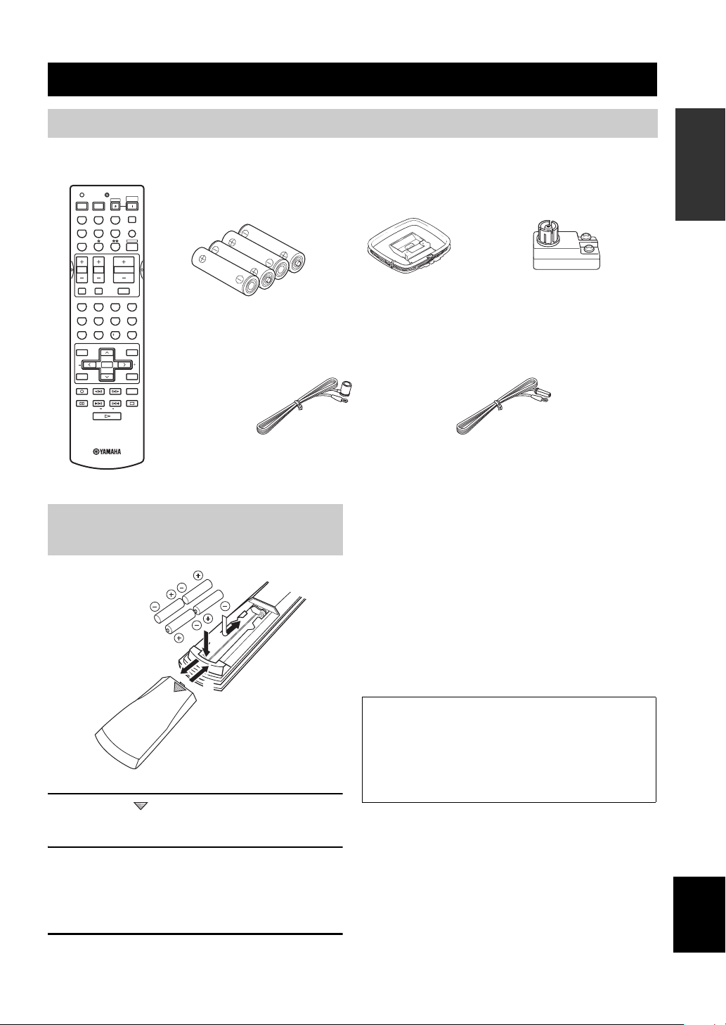
Supplied accessories
Please check that you received all of the following parts.
Remote control
TRANSMITCODE SET
CD
DVD
VCR
TV VOL TV CH
TV MUTE TV INPUT
LEVEL
TEST
REC
DISC SKIP
FREQ/RDS
MD/CD-R
DTV/CBL
SYSTEM
POWERPOWER
STANDBY
POWER
AVTV
TUNER
SLEEP
V-AUX
MULTI CH IN
AMP
VOLUME
MUTE
ROCKJAZZHALLSTEREO
4321
MOVIETV THTRMUSIC ENTERTAIN
81070965
STRAIGHT
EX/ESNIGHTq/DTS
ENTER
EFFECT
PRESET/CH
SET MENU
MENUTITLE
A/B/C/D/E
SELECT
DISPLAYRETURN
AUDIO
EONSTARTMODE PTY SEEK
RAV251
WC55290 EU
Batteries (4)
(AAA, R03, UM-4)
Indoor FM antenna
(U.S.A., Canada, China, Asia
and General models)
Installing batteries in the remote
control
2
1
3
1 Press the part and slide the battery
compartment cover off.
AM loop antenna
75-ohm/300-ohm antenna
adapter (U.K. model only)
Indoor FM antenna
(U.K., Europe, Australia
and Korea models)
Notes on batteries
• Change all of the batteries if you notice the condition like; the
operation range of the remote control decreases, the indicator
does not flash or its light becomes dim.
• Do not use old batteries together with new ones.
• Do not use different types of batteries (such as alkaline and
manganese batteries) together. Read the packaging carefully as
these different types of batteries may have the same shape and
color.
• If the batteries have leaked, dispose of them immediately. Avoid
touching the leaked material or letting it come into contact with
clothing, etc. Clean the battery compartment thoroughly before
installing new batteries.
If the remote control is without batteries for more than
2 minutes, or if exhausted batteries remain in the
remote control, the contents of the memory may be
cleared. When the memory is cleared, insert new
batteries, set up the manufacturer code and program
any acquired functions that may have been cleared.
INTRODUCTION
2 Insert four supplied batteries (AAA, R03,
UM-4) according to the polarity markings
(+ and –) on the inside of the battery
compartment.
3 Slide the cover back until it snaps into place.
English
3
CONTROLS AND FUNCTIONS
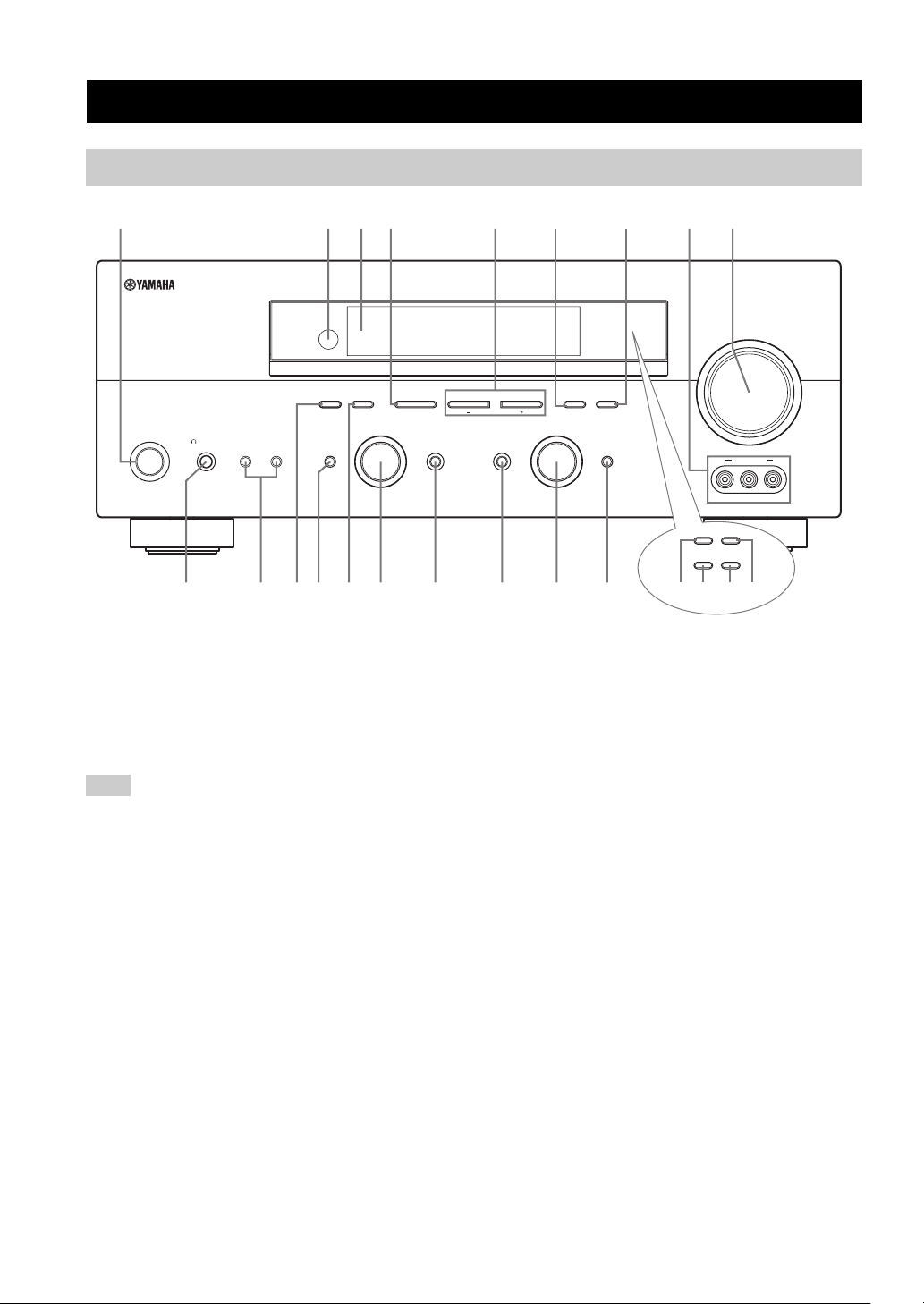
Front panel
CONTROLS AND FUNCTIONS
2134576
A/B/C/D/E
PROGRAM
EFFECT
STANDBY
/ON
PHONES
SILENT CINEMA
SPEAKERS
BA
0AC F
1 STANDBY/ON
Turns on this unit or sets it to the standby mode. When
you turn on this unit, you will hear a click and there will
be a 4 to 5-second delay before this unit can reproduce
sound.
Note
In standby mode, this unit consumes a small amount of power in
order to receive infrared-signals from the remote control.
2 Remote control sensor
Receives signals from the remote control.
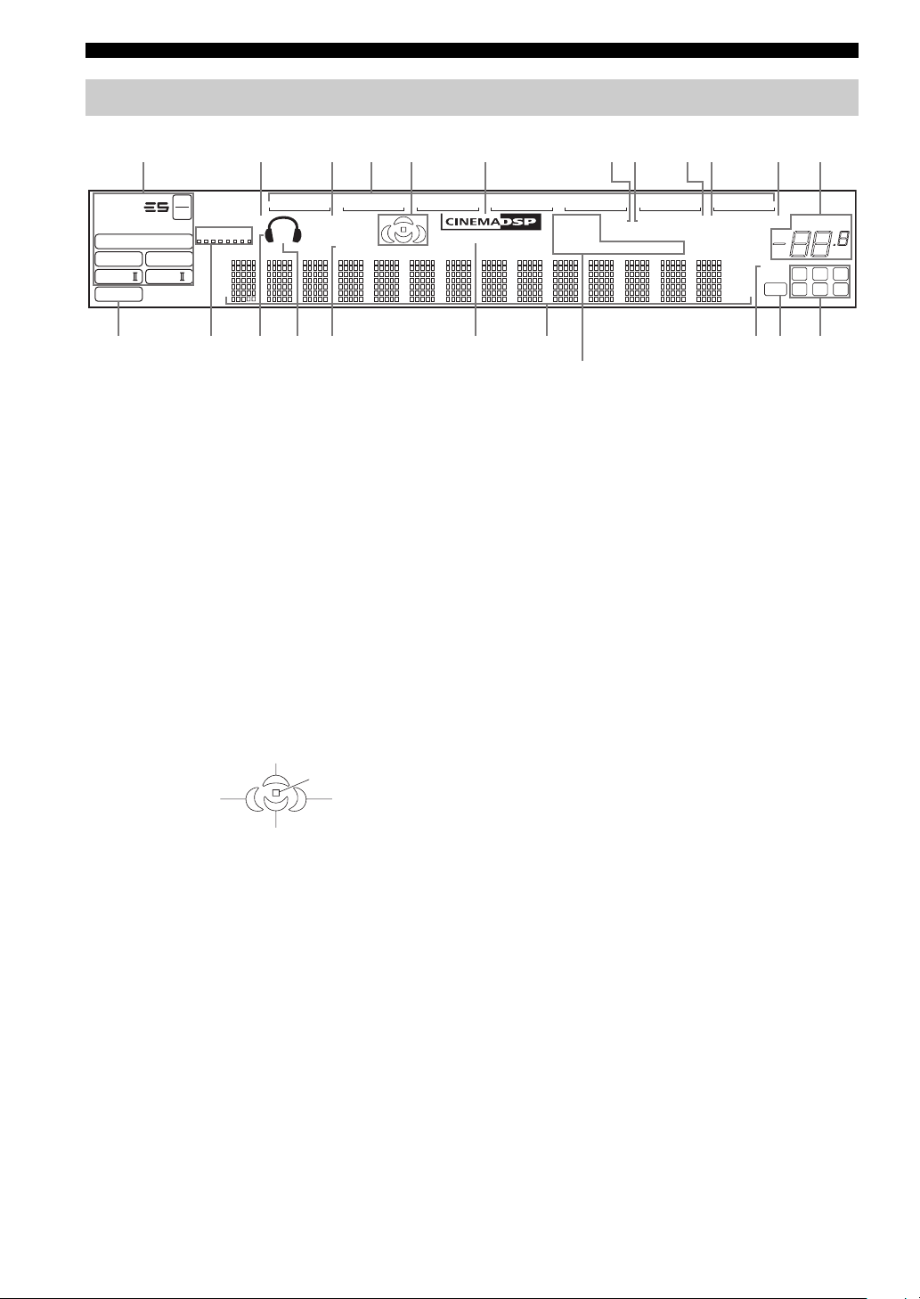
3 Front panel display
Shows information about the operational status of this
unit.
4 A/B/C/D/E (NEXT)
Selects one of the 5 preset station groups (A to E) when
the unit is in tuner mode.
Selects the speaker channel to be adjusted when the unit is
not in tuner mode.
9
8
(U.S.A. model)
VOLUME
l PRESET/TUNING h
INPUT MODETONE CONTROLSTRAIGHT
GHIEDB
MEMORYFM/AMPRESET/TUNING
TUNING MODE
AUTO/MAN’L MONOMAN’L/AUTO FMLEVELNEXTEDIT
INPUT
MULTI CH
INPUT
VIDEO L AUDIO R
RDS MODE/FREQ EON
PTY SEEK
MODE
VIDEO AUX
START
KLMJ
(U.K. and Europe models only)
5 PRESET/TUNING l / h (LEVEL –/+)
Selects preset station number 1 to 8 when the colon (:) is
displayed next to the band indication in the front panel
display when the unit is in tuner mode. Selects the tuning
frequency when the colon (:) is not displayed.
Adjusts the level of the speaker channel selected using
A/B/C/D/E (NEXT) when the unit is not in tuner mode.
6 MEMORY (MAN’L/AUTO FM)
Stores a station in the memory. Hold down this button for
more than 3 seconds to start automatic preset tuning.
7 TUNING MODE (AUTO/MAN’L MONO)
Switches between automatic tuning (AUTO indicator on)
and manual tuning (AUTO indicator off).
8 VIDEO AUX jacks
Input audio and video signals from a portable external
source such as a game console. To reproduce source
signals from these jacks, select V-AUX as the input source.
9 VOLUME
Controls the output level of all audio channels.
This does not affect the REC OUT level.
4

CONTROLS AND FUNCTIONS
0 PHONES (SILENT CINEMA) jack
Outputs audio signals for private listening with
headphones. When you connect headphones, no signals
are output to the OUTPUT jacks or to the speakers.
All Dolby Digital and DTS audio signals are mixed down
to the left and right headphone channels.
A SPEAKERS A/B
Turns on or off the set of front speakers connected to the A
and/or B terminals on the rear panel each time the
corresponding button is pressed.
B PRESET/TUNING (EDIT)
Switches the function of PRESET/TUNING l / h
(LEVEL –/+) between selecting preset station numbers
and tuning.
C STRAIGHT (EFFECT)
Switches the sound fields off or on. When STRAIGHT is
selected, input signals (2-channel or multi-channel) are
output directly from their respective speakers without
effect processing.
D FM/AM
Switches the reception band between FM and AM.
E PROGRAM
Use to select sound field programs or adjust the bass/
treble balance (in conjunction with TONE CONTROL).
F TONE CONTROL
Use to adjust the bass/treble balance for the front left and
right speakers (see page 27).
G INPUT MODE
Sets the priority (AUTO, DTS, ANALOG) for the type of
signals received when one component is connected to two
or more of this unit’s input jacks (see page 32).
H INPUT selector
Selects the input source you want to listen to or watch.
■ U.K. and Europe models only
J RDS MODE/FREQ
Press this button when the unit is receiving an RDS station
to cycle the display between the PS mode, PTY mode, RT
mode, CT mode (if the station offers those RDS data
services) and/or the frequency display.
K PTY SEEK MODE
Press this button to set the unit to the PTY SEEK mode.
L PTY SEEK START
Press this button to begin searching for a station after the
desired program type has been selected in the PTY SEEK
mode.
M EON
Press this button to select a radio program type (NEWS,
INFO, AFFAIRS, SPORT) to tune in automatically.
INTRODUCTION
I MULTI CH INPUT
Selects the source connected to the MULTI CH INPUT
jacks. When selected, the MULTI CH INPUT source takes
priority over the source selected with INPUT (or the input
selector buttons on the remote control).
English
5
CONTROLS AND FUNCTIONS
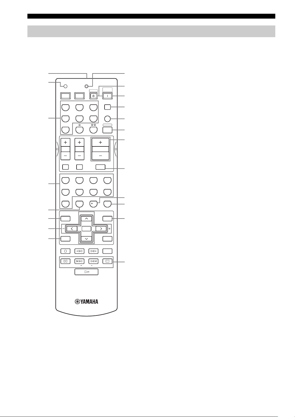
Remote control
This section describes the function of each control on the
remote control used to control this unit. To operate other
components, see “REMOTE CONTROL FEATURES” on
page 54.
1
2
TRANSMITCODE SET
POWERPOWER
AVTV
CD
MD/CD-R
STANDBY
TUNER
SYSTEM
POWER
SLEEP
9
0
A
B
DTV/CBL
V-AU X
MULTI CH IN
C
AMP
3
DVD
VCR
D
E
65
09
PRESET/CH
SELECT
EX/ESNIGHTq/DTS
VOLUME
7
10
MUTE
ROCKJAZZHALLSTEREO
4321
MOVIETV THTRMUSIC ENTERTAIN
8
STRAIGHT
ENTER
EFFECT
SET MENU
MENUTITLE
A/B/C/D/E
DISPLAYRETURN
AUDIO
EONSTART
F
G
H
I
J
4
5
6
7
8
TV VOL TV CH
TV MUTE TV INPUT
LEVEL
TEST
REC
DISC SKIP
MODE PTY SEEK
FREQ/RDS
3 Input selector buttons
Select the input source and change the control area.
4 Sound field program / numeric buttons
Use to select sound field programs.
Use numbers 1 through 8 to select preset stations when the
unit is in tuner mode.
5 NIGHT
Turns on or off the night listening modes (page 31).
6 LEVEL
Selects the speaker channel to be adjusted and sets the
level.
7 Cursor buttons u / d / j / i / SELECT
Use to select and adjust sound field program parameters or
SET MENU items.
Press u / d to select preset station numbers when the unit
is in tuner mode.
8 TEST (RETURN)
Outputs the test tone to adjust the speaker levels.
Returns to the previous menu level when adjusting the
SET MENU parameters.
9 TRANSMIT indicator
Flashes while the remote control is sending signals.
0 STANDBY
Sets this unit in the standby mode.
A SYSTEM POWER
Turns on the power of this unit.
B SLEEP
Sets the sleep timer.
C MULTI CH IN
Selects MULTI CH INPUT when using an external
decoder (etc.).
D AMP
Selects the AMP mode. You must select the AMP mode to
control the main unit.
1 Infrared window
Outputs infrared control signals. Aim this window at the
component you want to operate.
2 CODE SET
Use to set up manufacturer codes (see page 55).
6
E VOLUME –/+
Increases or decreases the volume level.
F MUTE
Mutes the sound. Press again to restore the audio output to
the previous volume level.
G EX/ES
Switches between 5.1 or 6.1-channel playback of multichannel software.
H STRAIGHT (EFFECT)
Switches the sound fields off or on. When STRAIGHT is
selected, input signals (2-channel or multi-channel) are
output directly from their respective speakers without
effect processing.
I SET MENU (A/B/C/D/E)
Activates the SET MENU function.
Selects preset station groups when the unit is in tuner
mode.
■ U.K. and Europe models only
J RDS tuning buttons
FREQ/RDS
Press this button when the unit is receiving an RDS station
to cycle the display between the PS mode, PTY mode, RT
mode, CT mode (if the station offers those RDS data
service) and/or the frequency display.
PTY SEEK MODE
Press this button to set the unit to the PTY SEEK mode.
PTY SEEK START
Press this button to begin searching for a station after the
desired program type has been selected in the PTY SEEK
mode.
EON
Press this button to select a radio program type (NEWS,
INFO, AFFAIRS, SPORT) to tune in automatically.
CONTROLS AND FUNCTIONS
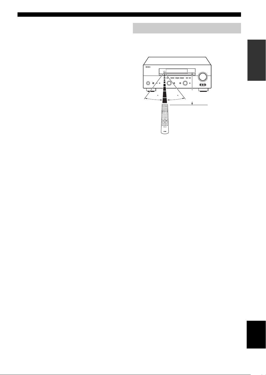
Using the remote control
The remote control transmits a directional infrared beam.
Be sure to aim the remote control directly at the remote
control sensor on the main unit during operation.
RDS MODE/FREQ EON
VOLUME
PTY SEEK
MODE
START
MEMORYFM/AMPRESET/TUNING
A/B/C/D/E
l PRESET/TUNING h
TUNING MODE
/ON
EFFECT
SILENT CINEMA
PROGRAM
PHONES
SPEAKERS
BA
STANDBY
30 30
TRANSMITCODE SET
SYSTEM
POWERPOWER
STANDBY
POWER
AVTV
CD
MD/CD-R
TUNER
SLEEP
V-AUX
DVD
DTV/CBL
MULTI CH IN
VCR
AMP
VOLUME
TV VOL TV CH
TV MUTE TV INPUT
MUTE
ROCKJAZZHALLSTEREO
4321
MOVIETV THTRMUSICENTERTAIN
81070965
EX/ESNIGHTq/DTS
STRAIGHT
ENTER
EFFECT
PRESET/CH
LEVEL
SET MENU
MENUTITLE
A/B/C/D/E
SELECT
TEST
DISPLAYRETURN
REC
AUDIO
DISC SKIP
■ Handling the remote control
• Do not spill water or other liquids on the remote
control.
• Do not drop the remote control.
• Do not leave or store the remote control in the
following types of conditions:
– high humidity such as near a bath
– high temperature such as near a heater or stove
– extremely low temperatures
– dusty places
AUTO/MAN’L MONOMAN’L/AUTO FMLEVELNEXTEDIT
INPUT
INPUT MODETONE CONTROLSTRAIGHT
MULTI CH
INPUT
VIDEO AUX
VIDEO L AUDIO R
Approximately 6 m
INTRODUCTION
7
English
CONTROLS AND FUNCTIONS
Front panel display
123456 780AB9
t
MATRIX DISCRETE
q
DIGITAL
q
q
EX
q
PL
q
PCM
PL x
96
24
SILENT CINEMA NIGHT PTY HOLD AUTO
VIRTUAL
PL
SP
A B
V-A UXVCR
SLEEP
DTV/CBL
FG
1 Decoder indicators
When any of this unit’s decoders function, the respective
indicator lights up.
2 SILENT CINEMA indicator
Lights up when headphones are connected and a sound
field program is selected (see page 27).
3 NIGHT indicator
Lights up when you select night listening mode.
4 Input source indicators
A cursor lights to show the current input source.
5 Sound field indicators
Light to indicate the active DSP sound fields.
CDTUNER
MEMORY
ft
mS
dB
96/24
LFE
HiFi DSP
DVD
MD/CD-R
TUNED STEREO MUTE
PS RT CT EONPTY
HI KLJEDC
(U.K. and Europe models only)
M
0 MEMORY indicator
Blinks to show that a station can be stored.
A MUTE indicator
Blinks while the MUTE function is on.
B VOLUME level indication
Indicates the volume level.
C PCM indicator
Lights up when this unit is reproducing PCM (pulse code
modulation) digital audio signals.
D VIRTUAL indicator
Lights up when Virtual CINEMA DSP is active (see
page 32).
VOLUME
dB
LCR
SL SB SR
Presence DSP sound field
Listening position
Left surround
DSP sound field
Surround back DSP sound field
Right surround
DSP sound field
6 CINEMA DSP indicator
Lights up when you select a CINEMA DSP sound field
program.
7 AUTO indicator
Lights up to indicate that automatic tuning is possible.
8 TUNED indicator
Lights up when this unit is tuned into a station.
9 STEREO indicator
Lights up when this unit is receiving a strong signal for an
FM stereo broadcast while the AUTO indicator is lit.
8
E Headphones indicator
Lights up when headphones are connected.
F SP A B indicators
Light up according to the set of front speakers selected.
Both indicators light up when both sets of speakers are
selected.
G SLEEP indicator
Lights up while the sleep timer is on.
H HiFi DSP indicator
Lights up when you select a HiFi DSP sound field
program.
I Multi-information display
Shows the current sound field program name and other
information when adjusting or changing settings.
J 96/24 indicator
Lights up when a DTS 96/24 signal is input to this unit.

K LFE indicator
Lights up when the input signal contains the LFE signal.
L Input channel indicators/speaker indicators
Indicate the channel components of the current digital
input signal.
Indicate the number of speakers connected in SPEAKERS
(page 24), or indicate the channel being adjusted in SP
LEVEL (page 51).
M RDS indicators
(U.K. and Europe models only)
The name(s) of the RDS data offered by the currently
received RDS station light(s) up.
EON lights up when an RDS station that offers the EON
data service is being received.
PTY HOLD lights up while searching for stations in the
PTY SEEK mode.
CONTROLS AND FUNCTIONS
INTRODUCTION
9
English
CONTROLS AND FUNCTIONS
Rear panel
12 3 4
DIGITAL
INPUT
COAXIAL
OPTICAL
DTV/CBL
DVD
MD/CD-R
MD/CD-R
OPTICAL
DIGITAL
OUTPUT
COMPONENT VIDEO
MULTI CH INPUT
R
FRONT
SURROUND
CD
SUB
WOOFER
CD
IN
(
)
PLAY
MD
/CD-R
OUT
(
)
REC
R
AUDIO
AUDIO
L
L
CENTER
L
VIDEO
R
DVD
DTV
/CBL
IN
VCR
OUT
VIDEO
SUB
WOOFER
OUTPUT
VIDEO
MONITOR OUT
S VIDEO
S VIDEO
DVD
DTV
/CBL
MONITOR
OUT
TUNER
AM
ANT
GND
FM
ANT
P
R
75Ω UNBAL.
Y
P
B
+
+
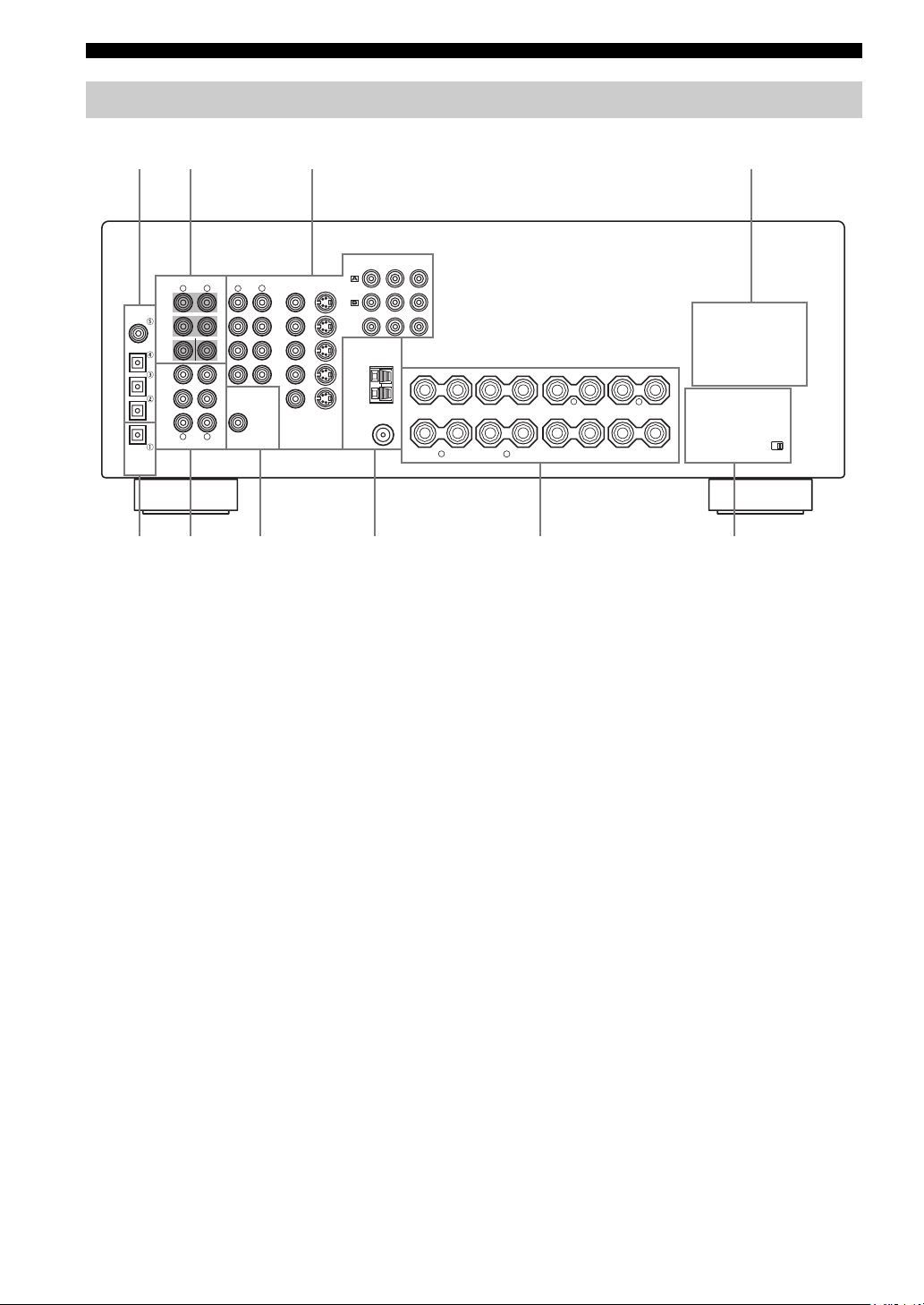
1 DIGITAL INPUT jacks
See pages 15, 17 and 18 for details.
2 MULTI CH INPUT jacks
See page 16 for connection information.
3 Video component jacks
See pages 15 and 17 for connection information.
4 AC OUTLET(S)
Use to supply power to your other A/V components (see
page 20).
5 DIGITAL OUTPUT jack
See page 18 for details.
6 Audio component jacks
See page 18 for connection information.
–
+
+
SPEAKERS
–
A
B
+
–
–
FRONT
R
+
L
CENTER
––
R
SURROUND
–
–
SURROUND BACK
L
7 SUB WOOFER OUTPUT jack
See page 13 for connection information.
8 Antenna terminals
See page 19 for connection information.
9 Speaker terminals
See page 13 for connection information.
0 IMPEDANCE SELECTOR switch
See page 21.
< Asia and General models only >
FREQUENCY STEP switch
See page 19.
VOLTAGE SELECTOR
See page 20.
+
IMPEDANCE SELECTOR
+
10
SPEAKER SETUP
SPEAKER SETUP
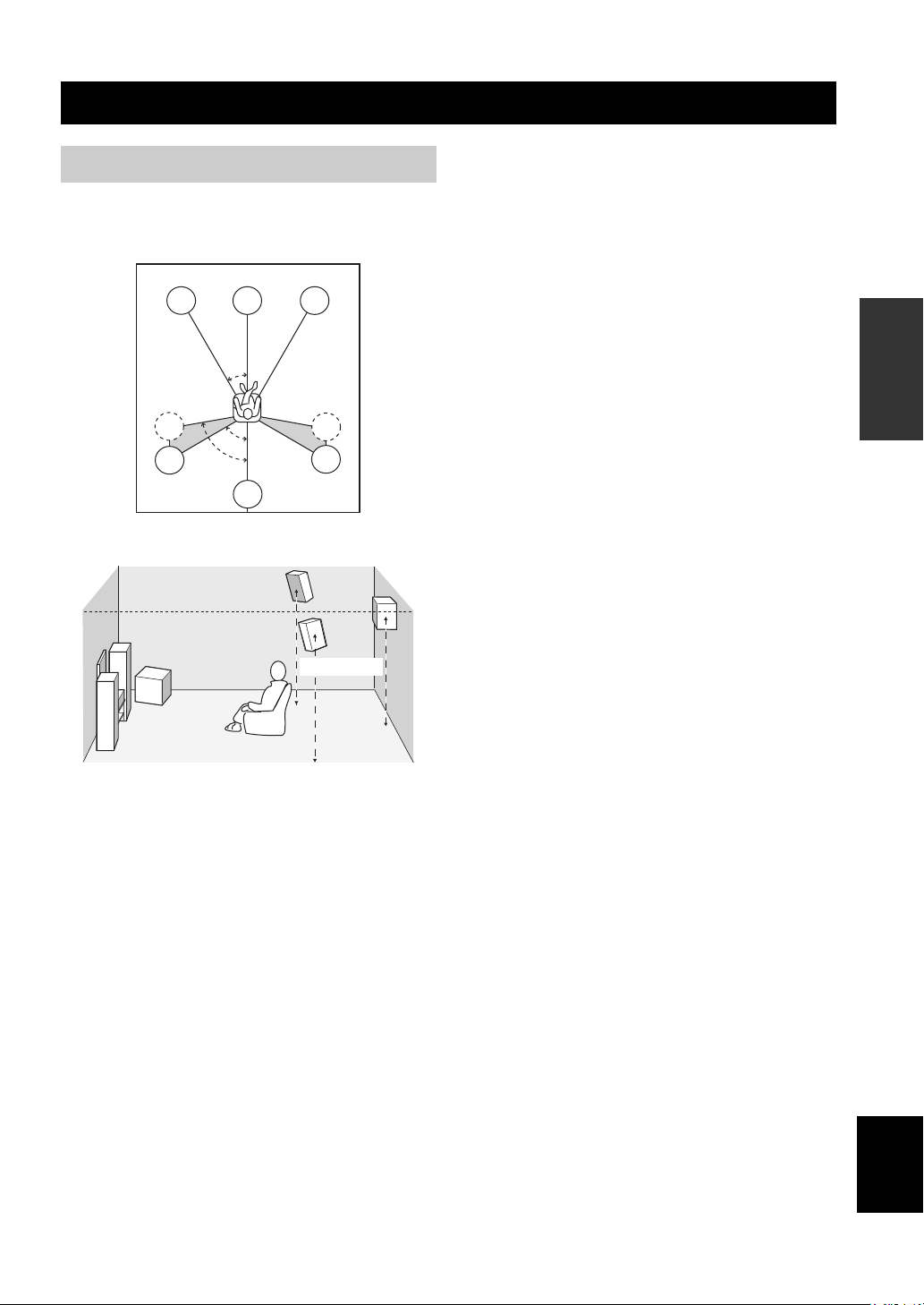
Speaker placement
The speaker layout below shows the standard ITU-R
speaker setting. You can use it to enjoy CINEMA DSP
and multi-channel audio sources.
FL
SL
SL
C
30˚
60˚
80˚
SB
FR
SR
SR
1.8 m
Surround speakers (SR and SL)
The surround speakers are used for effect and surround
sounds. Place these speakers behind your listening
position, facing slightly inwards, about 1.8 m above the
floor.
Surround back speaker (SB)
The surround back speaker supplements the surround
speakers and provides for more realistic front-to-back
transitions. Place this speaker directly behind the listening
position and at the same height as the surround speakers.
Subwoofer
The use of a subwoofer, such as the YAMAHA Active
Servo Processing Subwoofer System, is effective not only
for reinforcing bass frequencies from any or all channels,
but also for high fidelity reproduction of the LFE (lowfrequency effect) channel included in Dolby Digital and
DTS software. The position of the subwoofer is not so
critical, because low bass sounds are not highly
directional. But it is better to place the subwoofer near the
front speakers. Turn it slightly toward the center of the
room to reduce wall reflections.
PREPARATION
Front speakers (FR and FL)
The front speakers are used for the main source sound plus
effect sounds. Place these speakers an equal distance from
the ideal listening position. The distance of each speaker
from each side of the video monitor should be the same.
Center speaker (C)
The center speaker is for the center channel sounds
(dialog, vocals, etc.). If for some reason it is not practical
to use a center speaker, you can do without it. Best results,
however, are obtained with the full system. Align the front
face of the center speaker with the front face of your video
monitor. Place the speaker centrally between the front
speakers and as close to the monitor as possible, such as
directly over or under it.
English
11
SPEAKER SETUP
Speaker connections
Be sure to connect the left channel (L), right channel (R),
“+” (red) and “–” (black) properly. If the connections are
faulty, no sound will be heard from the speakers, and if the
polarity of the speaker connections is incorrect, the sound
will be unnatural and lack bass.
CAUTION
• If you will use 6 ohm speakers, be sure to set
this unit’s speaker impedance setting to 6
ohms before using (see page 21).
• Before connecting the speakers, make sure that the
power of this unit is off.
• Do not let the bare speaker wires touch each other or
do not let them touch any metal part of this unit. This
could damage this unit and/or speakers.
• Use magnetically shielded speakers. If this type of
speakers still creates the interference with the monitor,
place the speakers away from the monitor.
A speaker cord is actually a pair of insulated cables
running side by side. One cable is colored or shaped
differently, perhaps with a stripe, groove or ridges.
Connect the striped (grooved, etc.) cable to the “+” (red)
terminals on this unit and your speaker. Connect the plain
cable to the “–” (black) terminals.
10 mm
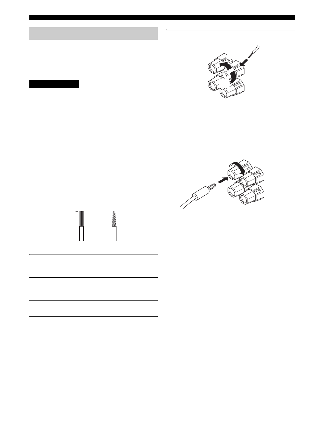
5 Tighten the knob to secure the wire.
3
4
5
Red: positive (+)
Black: negative (–)
■ Banana plug connections
(With the exception of U.K., Europe and Asia models)
First, tighten the knob and then insert the banana plug
connector into the end of the corresponding terminal.
Banana plug
(With the exception of U.K., Europe
and Asia models)
1
2
1 Remove approximately 10 mm of insulation
from the end of each speaker cable.
2 Twist the exposed wires of the cable together
to prevent short circuits.
3 Unscrew the knob.
4 Insert one bare wire into the hole in the side
of each terminal.
12
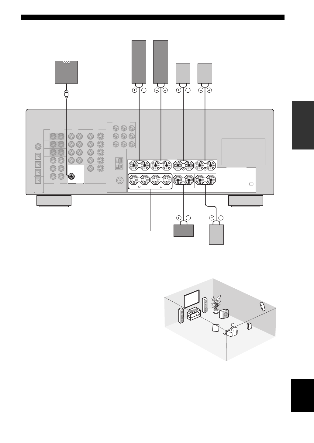
Front speakers (A)
LeftRight
SPEAKER SETUP
Subwoofer
system
SUB
WOOFER
OUTPUT
Surround speakers
LeftRight
2 3 6 71
PREPARATION
+
+
–
A
B
–
FRONT
R
SPEAKERS
–
–
+
+
+
+
L
CENTER
––
R
SURROUND
–
–
L
SURROUND BACK
+
+
speakers
■ FRONT terminals
Connect one or two speaker systems to these terminals. If
you use only one speaker system, connect it to either the
FRONT A or B terminals.
■ CENTER terminals
Connect a center speaker to these terminals.
■ SURROUND terminals
Connect surround speakers to these terminals.
■ SUB WOOFER jack
Connect a subwoofer with built-in amplifier, such as the
YAMAHA Active Servo Processing Subwoofer System,
to this jack.
■ SURROUND BACK terminals
Connect a surround back speaker to these terminals.
Front
(B)
Center
speaker
3
Surround back
4
54
speaker
2
1
7
Speaker layout
6
5
English
13
CONNECTIONS
CONNECTIONS
Before connecting components
CAUTION
Do not connect this unit or other components to the mains
power until all connections between components are
complete.
■ Cable indications
Dust protection cap
Pull out the cap from the optical jack before you connect
the fiber optic cable. Do not discard the cap. When you are
not using the optical jack, be sure to put the cap back in
place. This cap protects the jack from dust.
For analog signals
left analog cables
right analog cables
For digital signals
optical cables
coaxial cables
For video signals
video cables
S-Video cables
L
R
O
C
V
S
V
■ Analog jacks
You can input analog signals from audio components by
connecting audio pin cable to the analog jacks on this unit.
Connect red plugs to the right jacks and white plugs to the
left jacks.
■ Digital jacks
This unit has digital jacks for direct transmission of digital
signals through either coaxial or fiber optic cables. You
can use the digital jacks to input PCM, Dolby Digital and
DTS bitstreams. When you connect components to both
the COAXIAL and OPTICAL jacks, priority is given to
the input signals from the COAXIAL jack. All digital
input jacks are compatible with 96-kHz sampling digital
signals.
Note
This unit handles digital and analog signals independently. Thus
audio signals input to the analog jacks are only output to the
analog OUT (REC) jacks. Likewise audio signals input to the
digital (OPTICAL or COAXIAL) jacks are only output to the
DIGITAL OUTPUT jack.
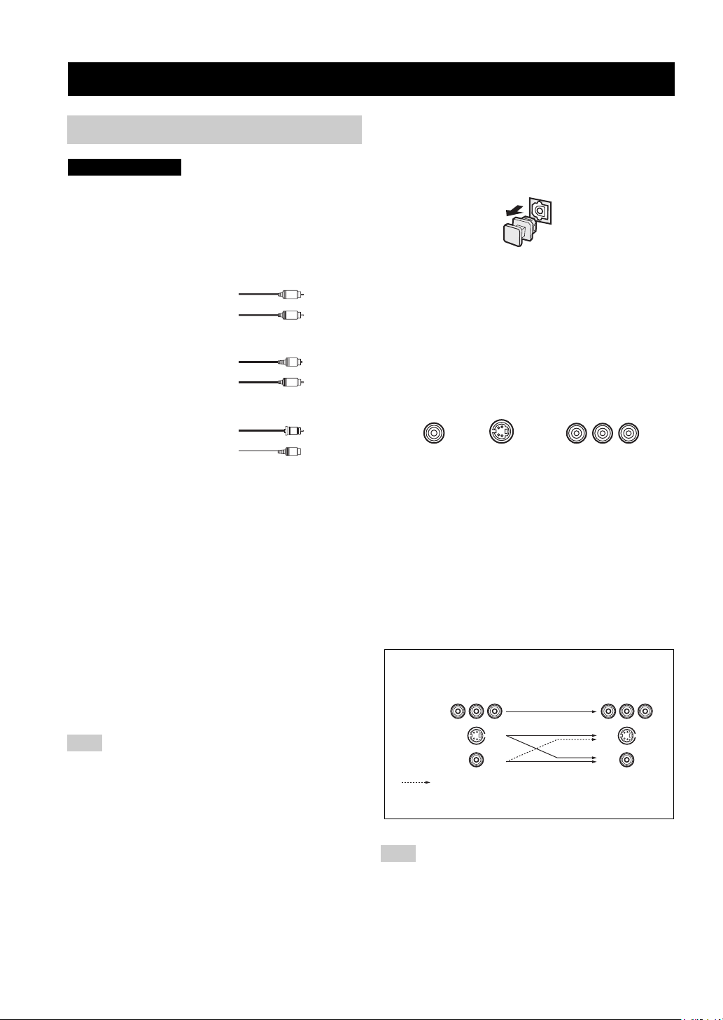
■ Video jacks
This unit has three types of video jacks. Connection
depends on the availability of input jacks on your monitor.
The signals input through the S VIDEO jacks on this unit
are automatically converted for output through the
VIDEO jacks. When V CONV. is set to ON (see page 53),
signals input through the VIDEO jacks can be output
through the S VIDEO jacks.
VIDEO
S VIDEO
VIDEO jack
For conventional composite video signals.
S VIDEO jack
For S-Video signals, separated into luminance (Y) and
color (C) video signals to achieve high-quality color
reproduction.
COMPONENT VIDEO jacks
For component signals, separated into luminance (Y) and
color difference (P
B, PR) to provide the best quality in
picture reproduction.
Signal flow inside this unit
Input
COMPONENT
VIDEO
S VIDEO
VIDEO
Only when V CONV. is set to ON
(see page 53).
COMPONENT VIDEO
PR PB Y
Output
(MONITOR OUT)
14
Note
When signals are input through both the S VIDEO and VIDEO
jacks, signals input through the S VIDEO jack have priority.
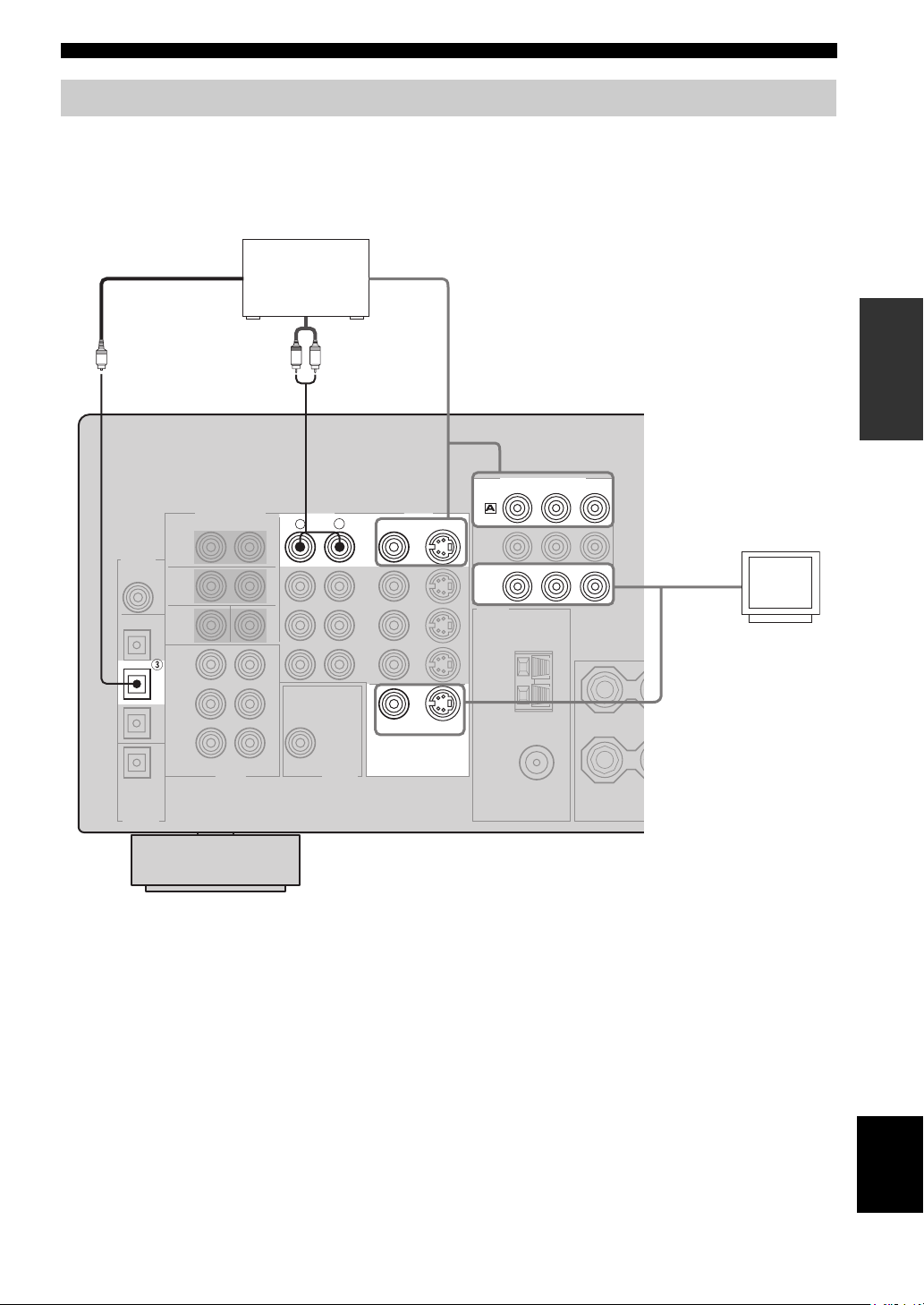
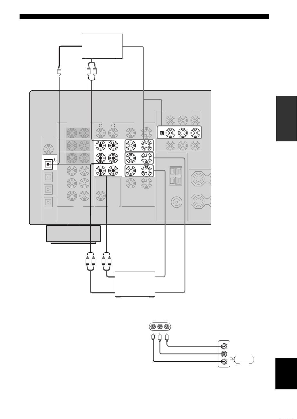
Connecting video components
■ Connections for DVD playback
CONNECTIONS
Optical out
DVD player
Video out
PREPARATION
Audio out
R
LR
AUDIO
COMPONENT VIDEO
PR
S VIDEO
S VIDEO
DVD
MONITOR
OUT
DVD
VIDEO
VIDEO
MONITOR OUT
VIDEO
L
Y
PB
Video in
Video
monitor
O
DVD
15
English
CONNECTIONS
■ Connecting to the MULTI CH INPUT jacks
This unit is equipped with 6 additional input jacks (left and right FRONT, CENTER, left and right SURROUND and
SUB WOOFER) for discrete multi-channel input from a multi-format player, external decoder, sound processor or preamplifier.
Connect the output jacks on your multi-format player or external decoder to the MULTI CH INPUT jacks. Be sure to
match the left and right outputs to the left and right input jacks for the front and surround channels.
MULTI CH INPUT
R
L
FRONT
SURROUND
SUB
WOOFER
CENTER
LR
Subwoofer
LR
out
Center
out
Multi-format player/
External decoder
Front
out
Surround
out
Notes
• When you select MULTI CH INPUT as the input source, this unit automatically turns off the digital sound field processor, and you
cannot select sound field programs.
• This unit does not redirect signals input to the MULTI CH INPUT jacks to accommodate for missing speakers. We recommend that
you connect at least a 5.1-channel speaker system before using this feature.
• When headphones are used, only front left and right channels are output.
16
■ Connections for other video components
CONNECTIONS
DIGITAL
INPUT
COAXIAL
OPTICAL
DTV/CBL
O
CD
Optical out
Audio out
Cable TV or
satellite tuner
LR
AUDI O
R
Video out
PREPARATION
COMPONENT VIDEO
PB Y
PR
VIDEO
VIDEO
S VIDEO
DTV
/CBL
L
DTV
/CBL
IN
VCR
OUT
LR LR
Audio in
Audio out Video out
DVD recorder
or VCR
■ VIDEO AUX jacks (on the front panel)
Use these jacks to connect any video source, such as a
game console or video camera, to this unit.
Video in
VIDEO AUX
VIDEO L AUDIO R
V
L
R
Game
Audio out R
Audio out L
Video out
console or
video camera
English
17
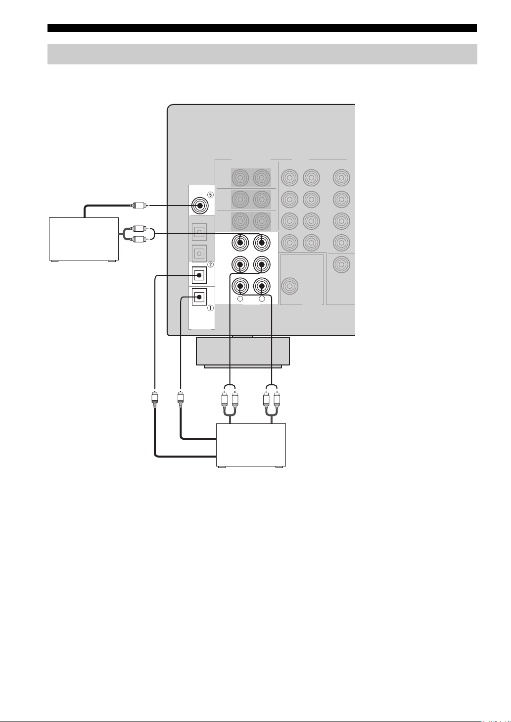
CONNECTIONS
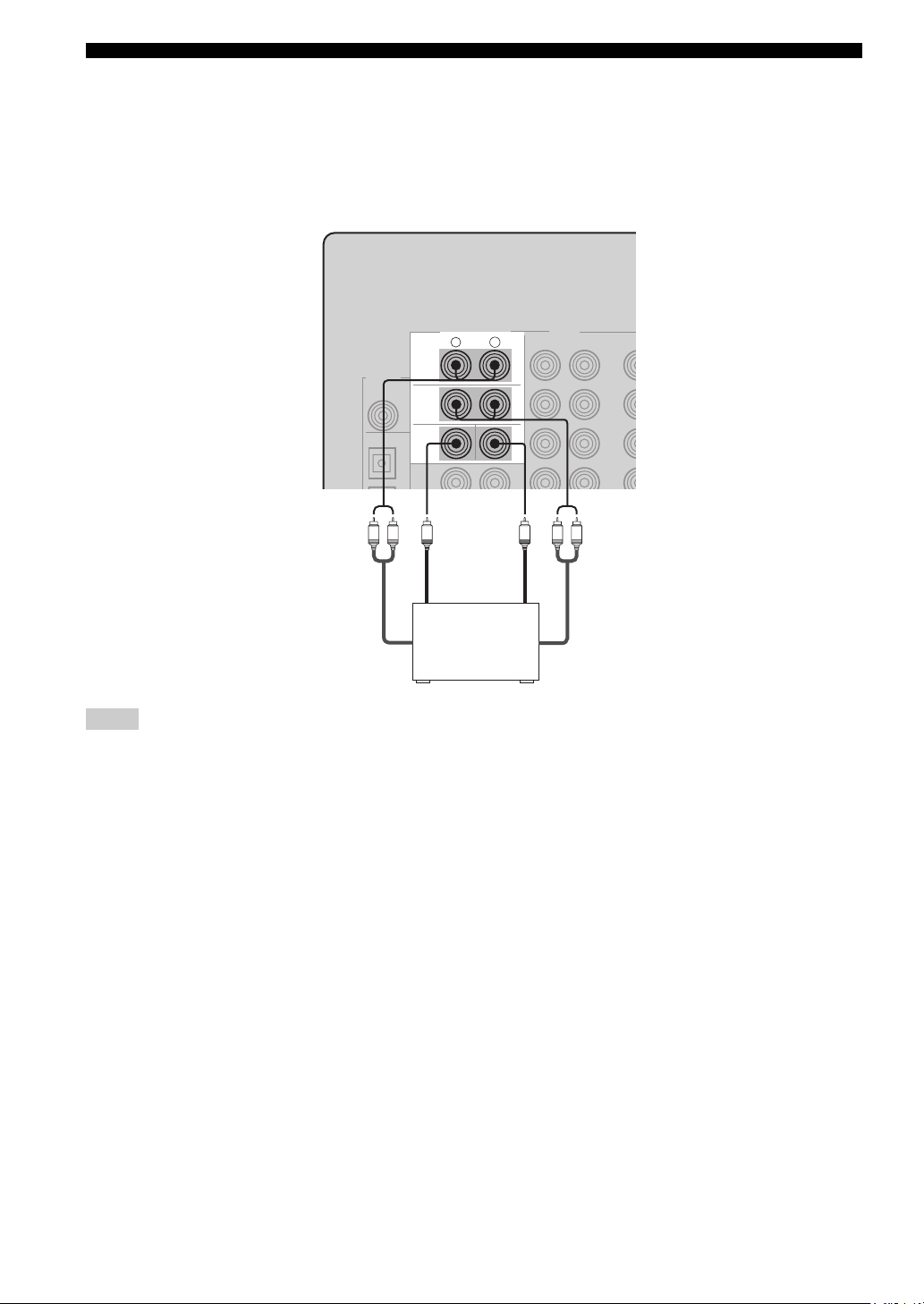
Connecting audio components
■ Connections for audio components
DIGITAL
INPUT
COAXIAL
CD
CD player
Coaxial out
C
Audio out
L
R
CD
Audio out
IN
(
)
PLAY
MD
/CD-R
(
)
REC
R
L
AUDI O
LR LR
MD recorder or
tape deck
Audio in
MD/CD-R
MD/CD-R
OPTICAL
DIGITAL
OUTPUT
O
O
Optical in
Optical out
18
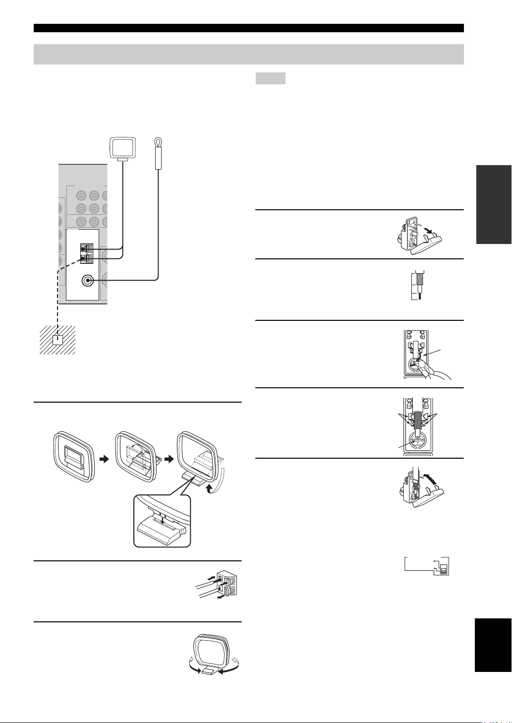
Connecting the antennas
CONNECTIONS
Both AM and FM indoor antennas are included with this
unit. In general, these antennas should provide sufficient
signal strength. Connect each antenna correctly to the
designated terminals.
AM loop antenna
(included)
TUNER
AM
ANT
GND
75Ω UNBAL.
FM
ANT
Ground (GND terminal)
For maximum safety and minimum interference,
connect the antenna
ground. A good earth ground is a metal stake driven
into moist earth.
Indoor FM antenna
(included)
GND terminal to a good earth
Notes
• The AM loop antenna should be placed away from this unit.
• The AM loop antenna should always be connected, even if an
outdoor AM antenna is connected to this unit.
• A properly installed outdoor antenna provides clearer reception
than an indoor one. If you experience poor reception quality, an
outdoor antenna may improve the quality. Consult the nearest
authorized YAMAHA dealer or service center about outdoor
antennas.
■ 75-ohm/300-ohm antenna adapter
(U.K. model only)
1 Open the cover of the
included 75-ohm/300-ohm
antenna adapter.
2 Cut the external sleeve
of the 75-ohm coaxial
cable and prepare it for
11 mm
8 mm
6 mm
connection.
3 Cut the lead wire and
remove it.
Lead wire
PREPARATION
■ Connecting the AM loop antenna
1 Set up the AM loop antenna, then connect it
to the terminals on this unit.
2 Press and hold the tab to insert
the AM loop antenna lead wires
into the AM ANT and GND
terminals.
3 Orient the AM loop antenna
for the best reception.
4 Insert the cable
wire into the slot,
and clamp it with
pliers.
Clamp
Insert wire into
slot.
Clamp
5 Snap the cover
into place.
■ FREQUENCY STEP switch
(Asia and General models only)
Because the interstation frequency
spacing differs in different areas, set
the FREQUENCY STEP switch
(locating on the rear panel) according
to the frequency spacing in your area.
• North, Central and South America: 100 kHz/10 kHz
• Other areas: 50 kHz/9 kHz
Before setting this switch, disconnect this unit’s power
cord from the AC wall outlet.
FREQUENCY STEP
10KHZ / 100KH
Z
FMAM
9KHZ / 50KH
Z
English
19
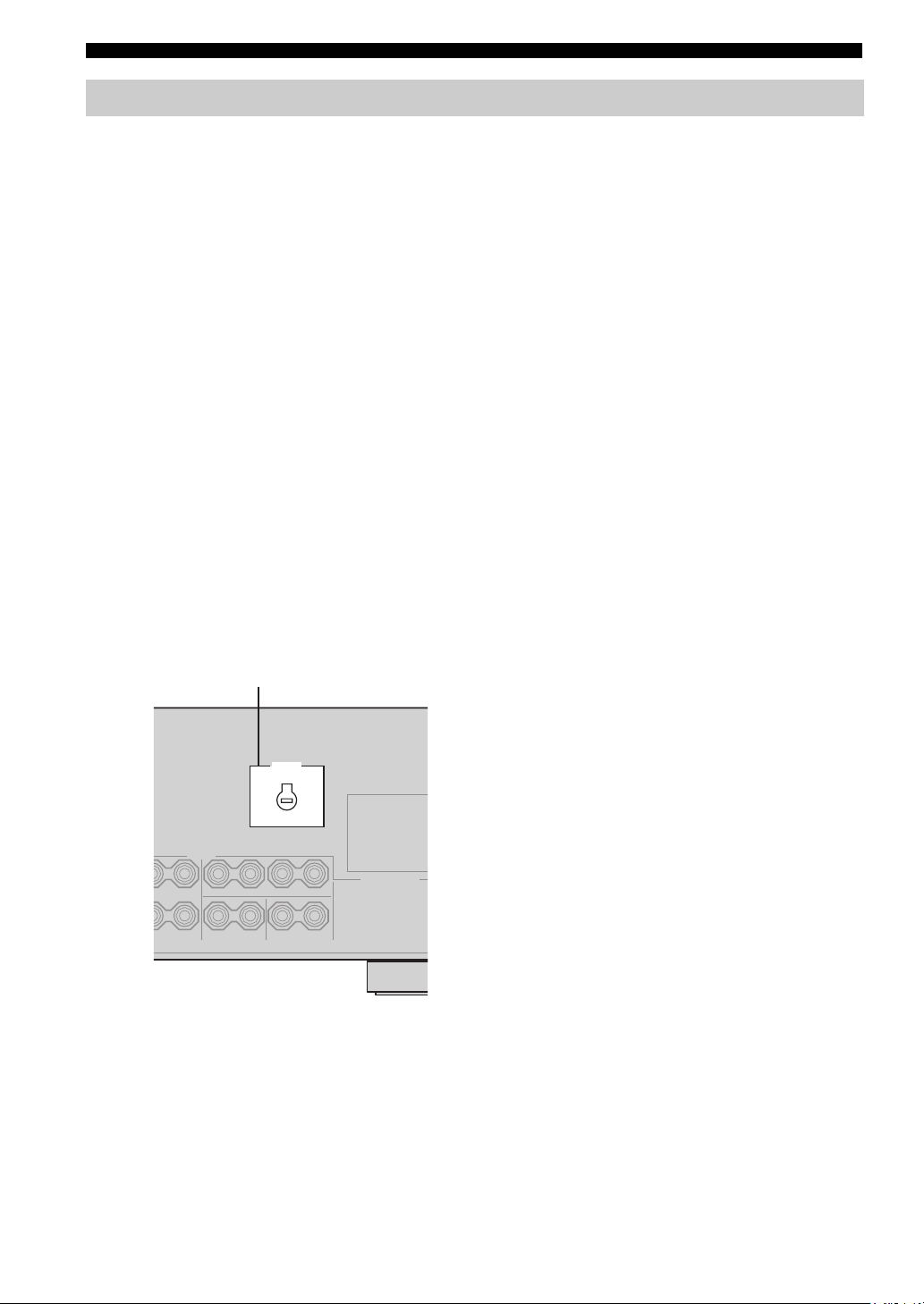
CONNECTIONS
Connecting the power supply cord
■ Connecting the AC power cord
Plug the power cord into an AC wall outlet.
■ AC OUTLET(S) (SWITCHED)
U.K. and Australia models ………………………… 1 OUTLET
Korea model ………………………………………………………None
Other models …………………………………………..2 OUTLETS
Use these outlets to connect the power cords from your
other components to this unit. Power to the AC
OUTLET(S) is controlled by this unit’s STANDBY/ON
(or SYSTEM POWER and STANDBY). The outlet(s)
supply power to any connected component whenever this
unit is turned on. The maximum power (total power
consumption of components) that can be connected to the
AC OUTLET(S) is:
Asia and General models……………………………………. 50 W
Korea model ………………………………………………………. N/A
Other models …………………………………………………..100 W
■ VOLTAGE SELECTOR
(Asia and General models only)
The VOLTAGE SELECTOR on the rear panel of this unit
must be set for your local main voltage BEFORE plugging
into the AC main supply. Voltages are:
Asia model ……………………..220/230-240 V AC, 50/60 Hz
General model ……110/120/220/230-240 V AC, 50/60 Hz
■ Memory back-up
The memory back-up circuit prevents the stored data from
being lost even if this unit is in the standby mode.
However if the power cord is disconnected from the AC
wall outlet, or the power supply is cut for more than one
week, the stored data will be lost.
VOLTAGE SELECTOR
VOLTAGE
SELECTOR
(Asia and General models)
20
■ IMPEDANCE SELECTOR switch
CAUTION
Do not change the setting of the IMPEDANCE
SELECTOR switch when the unit power is switched on,
as doing so may damage the unit.
If this unit fails to turn on when STANDBY/ON is pressed
on either the front panel or remote control, the
IMPEDANCE SELECTOR switch may not be fully slid to
either position. If this is the case, slide the switch all the
way to either position when this unit is in standby mode.
Select the switch position (left or right) according to the
impedance of the speakers in your system.
Switch position Speaker Impedance level
If you use one set (A or B), the impedance of each speaker must be
Left
Front
4 Ω or higher.
If you use two sets (A and B), the impedance of each speaker must be
8 Ω or higher.
IMPEDANCE SELECTOR
SET BEFORE POWER ON
IMPEDANCE SELECTOR switch
CONNECTIONS
PREPARATION
Right
The impedance of each speaker must be 6 Ω or higher.Center, Surround, Surround back
If you use one set (A or B), the impedance of each speaker must be
8 Ω or higher.
Front
If you use two sets (A and B), the impedance of each speaker must be
16 Ω or higher.
The impedance of each speaker must be 8 Ω or higher.Center, Surround, Surround back
English
21
CONNECTIONS
TRANSMITCODE SET
STANDBY
SYSTEM
POWER
CD
MD/CD-R
TUNER
V-AUX
DVD
AMP
POWERPOWER
VOLUME
TV MUTE TV INPUT
TV VOL TV CH
AVTV
VCR
DTV/CBL
MULTI CH IN
SLEEP
Turning on the power
When all connections are complete, turn on the power of
this unit.
(U.S.A. model)
VOLUME
l PRESET/TUNING h
INPUT MODETONE CONTROLSTRAIGHT
MEMORYFM/AMPRESET/TUNING
TUNING MODE
AUTO/MAN’L MONOMAN’L/AUTO FMLEVELNEXTEDIT
INPUT
MULTI CH
INPUT
VIDEO AUX
VIDEO L AUDIO R
A/B/C/D/E
PHONES
SPEAKERS
STANDBY
/ON
SILENT CINEMA
PROGRAM
BA
EFFECT
1
1
1 Press STANDBY/ON (SYSTEM POWER on
the remote control) to turn on the power of
this unit.
SYSTEM
STANDBY
/ON
Front panel
or
POWER
Remote control
2 Turn on the video monitor connected to this
unit.
22
Loading…
YAMAHA ELECTRONICS CORPORATION, USA 6660 ORANGETHORPE AVE., BUENA PARK, CALIF. 90620, U.S.A.
YAMAHA CANADA MUSIC LTD. 135 MILNER AVE., SCARBOROUGH, ONTARIO M1S 3R1, CANADA
YAMAHA ELECTRONIK EUROPA G.m.b.H. SIEMENSSTR. 22-34, 25462 RELLINGEN BEI HAMBURG, F.R. OF GERMANY
YAMAHA ELECTRONIQUE FRANCE S.A. RUE AMBROISE CROIZAT BP70 CROISSY-BEAUBOURG 77312 MARNE-LA-VALLEE CEDEX02, FRANCE
YAMAHA ELECTRONICS (UK) LTD. YAMAHA HOUSE, 200 RICKMANSWORTH ROAD WATFORD, HERTS WD18 7GQ, ENGLAND
YAMAHA SCANDINAVIA A.B. J A WETTERGRENS GATA 1, BOX 30053, 400 43 VÄSTRA FRÖLUNDA, SWEDEN
YAMAHA MUSIC AUSTRALIA PTY, LTD. 17-33 MARKET ST., SOUTH MELBOURNE, 3205 VIC., AUSTRALIA
© 2004 All rights reserved.
Printed in Malaysia
WD06160
RX-V757
AV Receiver
ИНСТРУКЦИЯ ПО ЭКСПЛУАТАЦИИ
G
RX-V550
RXV550_G_cv.fm Page 1 Wednesday, January 21, 2004 11:35 AM
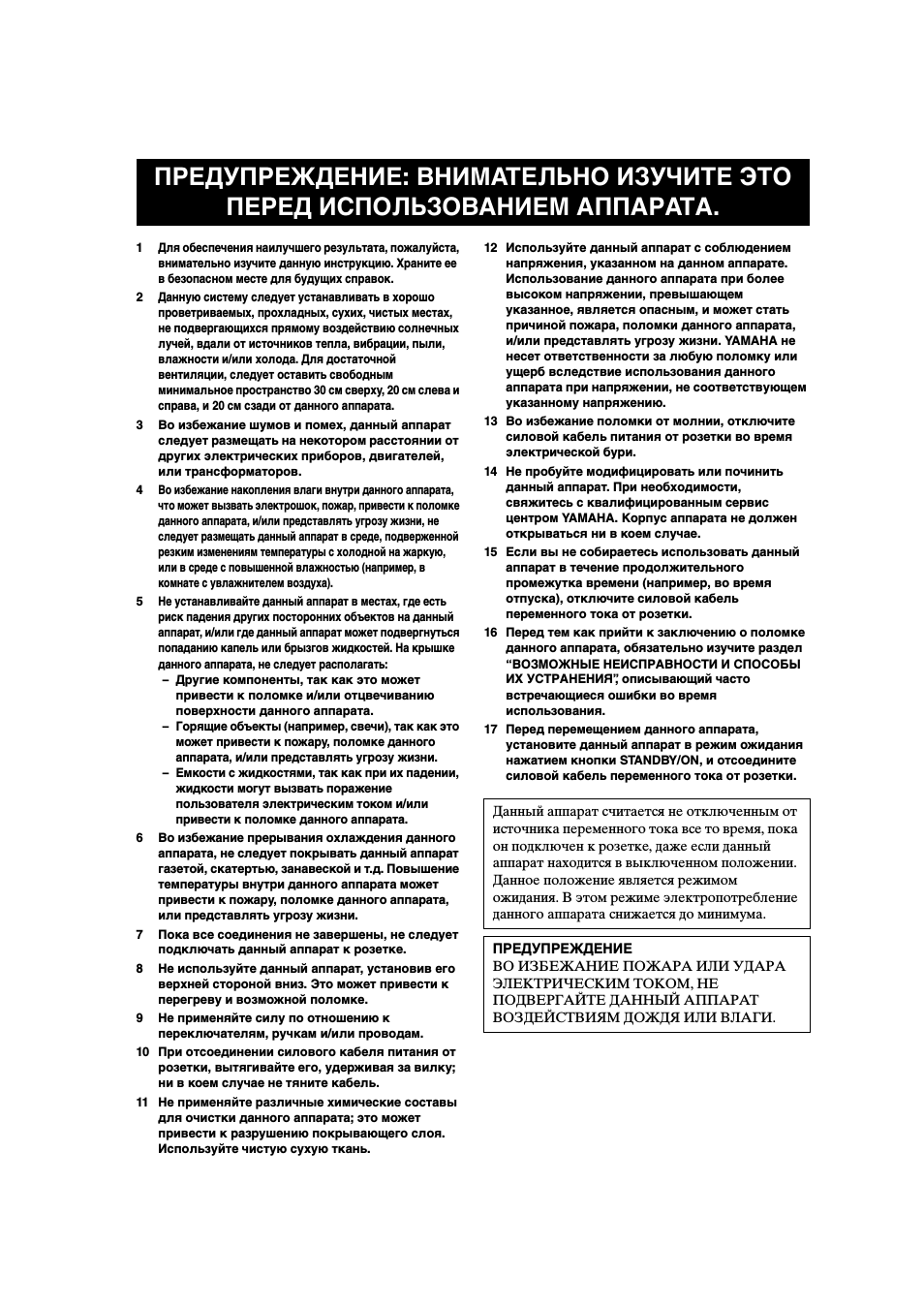
1
Для обеспечения наилучшего результата, пожалуйста,
внимательно изучите данную инструкцию. Храните ее
в безопасном месте для будущих справок.
2
Данную систему следует устанавливать в хорошо
проветриваемых, прохладных, сухих, чистых местах,
не подвергающихся прямому воздействию солнечных
лучей, вдали от источников тепла, вибрации, пыли,
влажности и/или холода. Для достаточной
вентиляции, следует оставить свободным
минимальное пространство 30 см сверху, 20 см слева и
справа, и 20 см сзади от данного аппарата.
3
Во избежание шумов и помех, данный аппарат
следует размещать на некотором расстоянии от
других электрических приборов, двигателей,
или трансформаторов.
4
Во избежание накопления влаги внутри данного аппарата,
что может вызвать электрошок, пожар, привести к поломке
данного аппарата, и/или представлять угрозу жизни, не
следует размещать данный аппарат в среде, подверженной
резким изменениям температуры с холодной на жаркую,
или в среде с повышенной влажностью (например, в
комнате с увлажнителем воздуха).
5
Не устанавливайте данный аппарат в местах, где есть
риск падения других посторонних объектов на данный
аппарат, и/или где данный аппарат может подвергнуться
попаданию капель или брызгов жидкостей. На крышке
данного аппарата, не следует располагать:
– Другие компоненты, так как это может
привести к поломке и/или отцвечиванию
поверхности данного аппарата.
– Горящие объекты (например, свечи), так как это
может привести к пожару, поломке данного
аппарата, и/или представлять угрозу жизни.
– Емкости с жидкостями, так как при их падении,
жидкости могут вызвать поражение
пользователя электрическим током и/или
привести к поломке данного аппарата.
6
Во избежание прерывания охлаждения данного
аппарата, не следует покрывать данный аппарат
газетой, скатертью, занавеской и т.д. Повышение
температуры внутри данного аппарата может
привести к пожару, поломке данного аппарата,
или представлять угрозу жизни.
7
Пока все соединения не завершены, не следует
подключать данный аппарат к розетке.
8
Не используйте данный аппарат, установив его
верхней стороной вниз. Это может привести к
перегреву и возможной поломке.
9
Не применяйте силу по отношению к
переключателям, ручкам и/или проводам.
10 При отсоединении силового кабеля питания от
розетки, вытягивайте его, удерживая за вилку;
ни в коем случае не тяните кабель.
11 Не применяйте различные химические составы
для очистки данного аппарата; это может
привести к разрушению покрывающего слоя.
Используйте чистую сухую ткань.
12 Используйте данный аппарат с соблюдением
напряжения, указанном на данном аппарате.
Использование данного аппарата при более
высоком напряжении, превышающем
указанное, является опасным, и может стать
причиной пожара, поломки данного аппарата,
и/или представлять угрозу жизни. YAMAHA не
несет ответственности за любую поломку или
ущерб вследствие использования данного
аппарата при напряжении, не соответствующем
указанному напряжению.
13 Во избежание поломки от молнии, отключите
силовой кабель питания от розетки во время
электрической бури.
14 Не пробуйте модифицировать или починить
данный аппарат. При необходимости,
свяжитесь с квалифицированным сервис
центром YAMAHA. Корпус аппарата не должен
открываться ни в коем случае.
15 Если вы не собираетесь использовать данный
аппарат в течение продолжительного
промежутка времени (например, во время
отпуска), отключите силовой кабель
переменного тока от розетки.
16 Перед тем как прийти к заключению о поломке
данного аппарата, обязательно изучите раздел
“ВОЗМОЖНЫЕ НЕИСПРАВНОСТИ И СПОСОБЫ
ИХ УСТРАНЕНИЯ”, описывающий часто
встречающиеся ошибки во время
использования.
17 Перед перемещением данного аппарата,
установите данный аппарат в режим ожидания
нажатием кнопки STANDBY/ON, и отсоедините
силовой кабель переменного тока от розетки.
ПРЕДУПРЕЖДЕНИЕ: ВНИМАТЕЛЬНО ИЗУЧИТЕ ЭТО
ПЕРЕД ИСПОЛЬЗОВАНИЕМ АППАРАТА.
Данный аппарат считается не отключенным от
источника переменного тока все то время, пока
он подключен к розетке, даже если данный
аппарат находится в выключенном положении.
Данное положение является режимом
ожидания. В этом режиме электропотребление
данного аппарата снижается до минимума.
ПРЕДУПРЕЖДЕНИЕ
ВО ИЗБЕЖАНИЕ ПОЖАРА ИЛИ УДАРА
ЭЛЕКТРИЧЕСКИМ ТОКОМ, НЕ
ПОДВЕРГАЙТЕ ДАННЫЙ АППАРАТ
ВОЗДЕЙСТВИЯМ ДОЖДЯ ИЛИ ВЛАГИ.
1
ПОДГО
ТОВКА
ВВЕДЕНИЕ
ОСНОВ
НОЕ
УП
РА
ВЛЕНИЕ
ПР
ОГ
Р
А
ММЫ
ЗВ
УК
ОВ
О
ГО П
О
Л
Я
Д
О
ПО
ЛН
ИТЕЛЬ
НЫ
Е
ОПЕРА
ЦИ
И
Д
О
ПО
ЛН
ИТЕЛ
ЬНА
Я
ИН
ФОРМАЦ
И
Я
Русский
ОПИСАНИЕ …………………………………………….. 2
ПОДГОТОВКА К ЭКСПЛУАТАЦИИ…………. 3
Поставляемые аксессуары ……………………………. 3
Установка батареек в пульт ДУ……………………. 3
СИСТЕМЫ УПРАВЛЕНИЯ И ФУНКЦИИ ….. 4
Фронтальная панель ……………………………………… 4
Пульт ДУ……………………………………………………….. 6
Использование пульта ДУ…………………………….. 7
Дисплей фронтальной панели ………………………. 8
Задняя панель………………………………………………. 10
УСТАНОВКА КОЛОНОК ……………………….. 11
Размещение колонок …………………………………… 11
Подключение колонок………………………………… 12
ПОДКЛЮЧЕНИЯ …………………………………… 15
Перед подключением компонентов ……………. 15
Подключение видеокомпонентов……………….. 16
Подключение аудиокомпонентов……………….. 19
Подключение ЧМ- и АМ-антенн………………… 21
Подключение силового кабеля питания …….. 22
Установка импеданса колонок ……………………. 23
Включение питания …………………………………….. 23
ФУНКЦИЯ АВТОМАТИЧЕСКОЙ
НАСТРОЙКИ (AUTO SETUP)………………. 24
Введение ………………………………………………………. 24
Установка микрофона оптимизатора…………. 24
Начало настройки ……………………………………….. 25
ВОСПРОИЗВЕДЕНИЕ……………………………. 30
Основные операции …………………………………….. 30
Выбор программ звукового поля………………… 32
Выбор режимов приема………………………………. 36
НАСТРОЙКА РАДИОПРОГРАММ
ДИАПАЗОНА ЧМ/AM ………………………….. 38
Автоматическая и ручная настройка………….. 38
Предустановка радиостанций ……………………… 39
Выбор предустановленных радиостанций….. 41
Замена предустановленных
радиостанций……………………………………………. 42
Прием радиостанций системы Radio Data
System……………………………………………………….. 43
Переключение режима Radio Data
System……………………………………………………….. 44
Функция PTY SEEK…………………………………….. 45
Функция EON………………………………………………. 46
ЗАПИСЬ………………………………………………… 47
ОПИСАНИЕ ПРОГРАММ ЗВУКОВОГО
ПОЛЯ…………………………………………………. 48
Для видеоисточников и кинофильмов………… 48
Для музыкальных источников…………………….. 50
ДОПОЛНИТЕЛЬНЫЕ ОПЕРАЦИИ………….. 51
Выбор режима дисплея на экране OSD ……… 51
Применение таймера сна …………………………….. 51
Настройка уровней колонок вручную………… 52
МЕНЮ НАСТРОЙКИ (SET MENU) ………….. 53
Использование SET MENU ………………………… 55
1 SOUND MENU…………………………………………. 56
2 INPUT MENU …………………………………………… 61
3 OPTION MENU………………………………………… 63
МЕНЮ ДОПОЛНИТЕЛЬНЫХ
НАСТРОЙКИ………………………………………. 65
ОПИСАНИЕ ПУЛЬТА
ДИСТАНЦИОННОГО УПРАВЛЕНИЯ …… 67
Зона управления ………………………………………….. 67
Установка кодов ДУ ……………………………………. 68
Управление другими компонентами …………… 69
Переключение кодов библиотек ………………… 70
Очистка установленных кодов ДУ……………… 70
ZONE 2 ………………………………………………….. 71
Подключения Zone 2 …………………………………… 71
Дистанционное управление Zone 2 …………….. 72
РЕДАКТИРОВАНИЕ ПАРАМЕТРОВ
ЗВУКОВОГО ПОЛЯ…………………………….74
Понятие звукового поля ……………………………… 74
Изменение настроек параметров………………… 74
ОПИСАНИЕ ПАРАМЕТРОВ
ЗВУКОВОГО ПОЛЯ…………………………….76
ВОЗМОЖНЫЕ НЕИСПРАВНОСТИ И
СПОСОБЫ ИХ УСТРАНЕНИЯ …………….. 81
СБРОС НАСТРОЕК В ИСХОДНЫЕ
НАСТРОЙКИ ……………………………………… 86
СПРАВОЧНИК ………………………………………. 87
Аудиоформаты ……………………………………………. 87
Программы звукового поля ………………………… 88
Аудиоинформация ………………………………………. 88
Информация о видеосигнале ………………………. 89
ТЕХНИЧЕСКИЕ ХАРАКТЕРИСТИКИ ……… 90
СОДЕРЖАНИЕ
ВВЕДЕНИЕ
ПОДГОТОВКА
ОСНОВНОЕ УПРАВЛЕНИЕ
ПРОГРАММЫ ЗВУКОВОГО ПОЛЯ
ДОПОЛНИТЕЛЬНЫЕ ОПЕРАЦИИ
ДОПОЛНИТЕЛЬНАЯ ИНФОРМАЦИЯ

ОПИСАНИЕ
2
Встроенный 7-канальный усилитель
мощности
◆ Минимальное среднеквадратическое выходное
напряжение
(0,06% ОНИ, 20 Гц – 20 кГц, 8

Фронтальный: 100 Ватт + 100 Ватт
Центральный: 100 Ватт
Окружающее звучание: 100 Ватт + 100 Ватт
Тыловое окружающее звучание:
100 Ватт + 100 Ватт
Описание звукового поля
◆ Собственная технология YAMAHA для
создания звуковых полей
◆ Декодер Dolby Digital/Dolby Digital EX
◆ Декодер DTS/DTS-ES Matrix 6.1, Discrete 6.1,
DTS Neo:6, DTS 96/24
◆ Декодер Dolby Pro Logic/Dolby Pro Logic II/
Dolby Pro Logic IIx
◆ Virtual CINEMA DSP
◆ SILENT CINEMA
™
Усовершенствованный AM/ЧМ тюнер
◆ Настройка со случайным доступом и
предустановка до 40 радиостанций
◆ Автоматическая предустановка
◆ Функция замены предустановленных
радиостанций (редактирование предустановки)
Другие особенности
◆ YPAO: Параметрический оптимизатор
акустики комнаты производства YAMAHA для
автоматической настройки колонок
◆ 192-кГц/24-битовый цифрово-аналоговый
преобразователь
◆ SET MENU, содержащее параметры,
позволяющие оптимизировать данный аппарат
под аудио/видеосистему
◆ 8 дополнительных входных гнезд для приема
дискретных многоканальных сигналов
◆ Функция PURE DIRECT для воспроизведения
высокоточного звучания от аналоговых
источников и источников формата PCM
◆ Функция дисплея на экране для облегчения
управления данным аппаратом
◆ Функция ввода/вывода S-видеосигнала
◆ Функция ввода/вывода компонентых
видеосигналов
◆ Функция изменения видеосигнала
(Композитное видео
l S-видео o
Компонентное видео) для вывода на экран
◆ Оптические и коаксиальные гнезда цифровых
аудиосигналов
◆ Таймер сна
◆ Режимы ночного прослушивания кинофильмов
и музыки
◆ Пульт ДУ с предустановленными кодами ДУ
◆ Оборудование по установке Zone 2 по вкусу
• y означает совет для облегчения управления.
• Некоторые операции могут производиться с использованием кнопок основного блока или пульта ДУ. В случаях,
если наименования кнопок основного блока не совпадают с наименованиями кнопок пульта ДУ, наименования
кнопок пульта ДУ указываются в скобках.
• Данное руководство отпечатано до производства. Дизайн и технические характеристики могут частично изменяться
с целью улучшения качества и т.д. В случае, если имеются различия между руководством и аппаратом, приоритет
отдается аппарату.
Изготовлено по лицензии фирмы Dolby Laboratories.
“Dolby”, “Pro Logic”, “Surround EX” и символ в виде двух
букв D являются товарными знаками компании Dolby
Laboratories.
“SILENT CINEMA” является торговой маркой
YAMAHA CORPORATION.
“DTS”, “DTS-ES”, “Neo:6” и “DTS 96/24” являются
торговыми марками Digital Theater Systems, Inc.
ОПИСАНИЕ
ПОДГОТОВКА К ЭКСПЛУАТАЦИИ
3
ВВЕДЕНИЕ
Русский
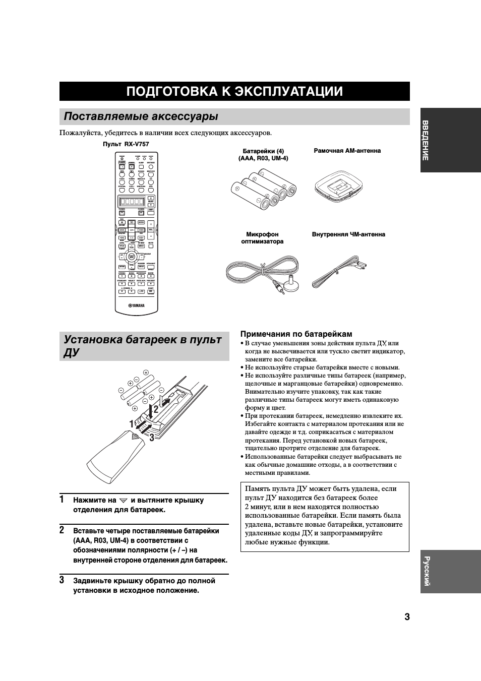
Пожалуйста, убедитесь в наличии всех следующих аксессуаров.
1
Нажмите на
и вытяните крышку
отделения для батареек.
2
Вставьте четыре поставляемые батарейки
(AAA, R03, UM-4) в соответствии с
обозначениями полярности (+ / –) на
внутренней стороне отделения для батареек.
3
Задвиньте крышку обратно до полной
установки в исходное положение.
Примечания по батарейкам
• В случае уменьшения зоны действия пульта ДУ, или
когда не высвечивается или тускло светит индикатор,
замените все батарейки.
• Не используйте старые батарейки вместе с новыми.
• Не используйте различные типы батареек (например,
щелочные и марганцовые батарейки) одновременно.
Внимательно изучите упаковку, так как такие
различные типы батареек могут иметь одинаковую
форму и цвет.
• При протекании батареек, немедленно извлеките их.
Избегайте контакта с материалом протекания или не
давайте одежде и т.д. соприкасаться с материалом
протекания. Перед установкой новых батареек,
тщательно протрите отделение для батареек.
• Использованные батарейки следует выбрасывать не
как обычные домашние отходы, а в соответствии с
местными правилами.
ПОДГОТОВКА К ЭКСПЛУАТАЦИИ
Поставляемые аксессуары
Пульт
Батарейки (4)
(AAA, R03, UM-4)
Рамочная АМ-антенна
Внутренняя ЧМ-антенна
Микрофон
оптимизатора
Установка батареек в пульт
ДУ
1
3
2
Память пульта ДУ может быть удалена, если
пульт ДУ находится без батареек более
2 минут, или в нем находятся полностью
использованные батарейки. Если память была
удалена, вставьте новые батарейки, установите
удаленные коды ДУ, и запрограммируйте
любые нужные функции.
TRANSMIT
RE-NAME
INPUT MODE
STANDBY
SYSTEM
POWER
A
B
PHONO
CD
MD/CD-R
TUNER
V-AUX
DVD
AMP
POWER
POWER
REC
AUDIO
MUTE
MENU
TITLE
CH
CH
VOL
DISC SKIP
SET MENU
LEVEL
PRESET
SRCH MODE
A/B/C/D/E
BAND
TV INPUT
TV VOL
ON SCREEN
STRAIGHT
MOVIE
ENTERTAIN
MUSIC
STEREO
4
3
2
1
8
10
7
0
9
6
5
ENT.
PURE DIRECT
EXTD SUR.
STANDARD
SELECT
NIGHT
SPEAKERS
A
B
EFFECT
MEMORY
CHP/INDEX
DISPLAY
RETURN
TV MUTE
ENTER
TV VOL
AV
TV
SELECT
VCR 1
DTV/CBL
DVR/VCR2
MULTI CH IN
SLEEP
CLEAR
LEARN
PRESET
FREQ/TEXT
EON
START
MODE
PTY SEEK
RX-V757
СИСТЕМЫ УПРАВЛЕНИЯ И ФУНКЦИИ
4
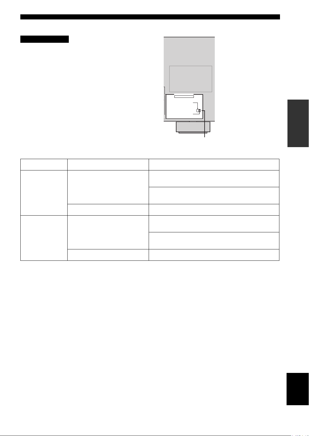
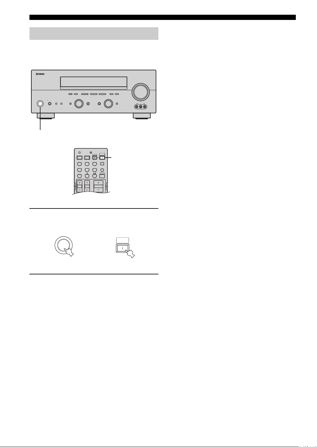
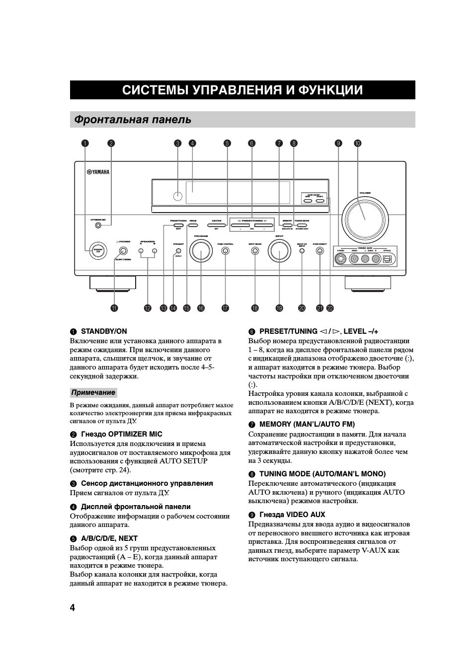
1 STANDBY/ON
Включение или установка данного аппарата в
режим ожидания. При включении данного
аппарата, слышится щелчок, и звучание от
данного аппарата будет исходить после 4–5-
секундной задержки.
В режиме ожидания, данный аппарат потребляет малое
количество электроэнергии для приема инфракрасных
сигналов от пульта ДУ.
2 Гнездо OPTIMIZER MIC
Используется для подключения и приема
аудиосигналов от поставляемого микрофона для
использования с функцией AUTO SETUP
(смотрите стр. 24).
3 Сенсор дистанционного управления
Прием сигналов от пульта ДУ.
4 Дисплей фронтальной панели
Отображение информации о рабочем состоянии
данного аппарата.
5 A/B/C/D/E, NEXT
Выбор одной из 5 групп предустановленных
радиостанций (A – E), когда данный аппарат
находится в режиме тюнера.
Выбор канала колонки для настройки, когда
данный аппарат не находится в режиме тюнера.
6 PRESET/TUNING l / h, LEVEL –/+
Выбор номера предустановленной радиостанции
1 – 8, когда на дисплее фронтальной панели рядом
с индикацией диапазона отображено двоеточие (:),
и аппарат находится в режиме тюнера. Выбор
частоты настройки при отключенном двоеточии
(:).
Настройка уровня канала колонки, выбранной с
использованием кнопки A/B/C/D/E (NEXT), когда
аппарат не находится в режиме тюнера.
7 MEMORY (MAN’L/AUTO FM)
Сохранение радиостанции в памяти. Для начала
автоматической настройки и предустановки,
удерживайте данную кнопку нажатой более чем
на 3 секунды.
8 TUNING MODE (AUTO/MAN’L MONO)
Переключение автоматического (индикация
AUTO включена) и ручного (индикация AUTO
выключена) режимов настройки.
9 Гнезда VIDEO AUX
Предназначены для ввода аудио и видеосигналов
от переносного внешнего источника как игровая
приставка. Для воспроизведения сигналов от
данных гнезд, выберите параметр V-AUX как
источник поступающего сигнала.
СИСТЕМЫ УПРАВЛЕНИЯ И ФУНКЦИИ
Фронтальная панель
MAIN
ZONE ON/OFF
ZONE 2
DISPLAY
S VIDEO
VIDEO
OPTICAL
L AUDIO R
CATEGORY
SEARCH MODE
EFFECT
XM
OPTIMIZER MIC
PROGRAM
PURE DIRECT
INPUT MODE
TONE CONTROL
STRAIGHT
SPEAKERS
PHONES
SILENT CINEMA
STANDBY
/ON
B
A
MULTI CH
INPUT
VOLUME
VIDEO AUX
INPUT
LEVEL
NEXT
MEMORY
FM/AM
PRESET/TUNING
A/B/C/D/E
l PRESET/TUNING h
TUNING MODE
MAN’L/AUTO FM
AUTO/MAN’L MONO
EDIT
3
1
4
5
2
6
0
9
J K
H
G
E
B
A
C D
F
I
L
7 8
Примечание
СИСТЕМЫ УПРАВЛЕНИЯ И ФУНКЦИИ
5
ВВЕДЕНИЕ
Русский
0 VOLUME
Управление уровнями вывода всех аудиоканалов.
Не воздействует на уровень REC OUT.
A Гнездо
PHONES (SILENT CINEMA)
Вывод аудиосигналов для индивидуального
прослушивания с использованием наушников. При
подключении наушников, выходные сигналы на
гнезда PRE OUT и колонки отсутствуют.
Все аудиосигналы форматов Dolby Digital и DTS микшируются
с выходом на левый и правый каналы наушников.
B SPEAKERS A/B
Включение или выключение системы
фронтальных колонок, подключенных к
терминалам A и/или B на задней панели, при
каждом нажатии соответствующей кнопки.
C PRESET/TUNING (EDIT)
Переключение функции PRESET/TUNING l / h
(LEVEL –/+) между режимами выбора номеров
предустановленных радиостанций и тюнера.
D STRAIGHT (EFFECT)
Включение или выключение звуковых полей. При
выборе функции STRAIGHT, поступающие сигналы (2-
канальные или многоканальные) напрямую выводятся
соответствующими колонками без эффектов.
E FM/AM
Переключение диапазона приема в режиме тюнера.
F PROGRAM
Выбор программ звуковых полей или настройка
баланса низких/высоких частот (вместе с
функцией TONE CONTROL).
G TONE CONTROL
Предназначена для настройки баланса низких/высоких частот
фронтальных левого и правого, центрального каналов и
каналов присутствия и сабвуфера (смотрите стр. 31).
H INPUT MODE
Установка приоритета (AUTO, DTS, ANALOG)
для типа поступающих сигналов при подключении
одного компонента к двум или более входным
гнездам данного аппарата (смотрите стр. 36).
I Селектор INPUT
Выбор желаемого источника поступающего
сигнала для прослушивания или просмотра.
J MULTI CH INPUT
Выбор источника, подключенного к гнездам MULTI
CH INPUT. Если выбран источник MULTI CH INPUT,
ему отдается приоритет над другим источником,
выбранным с использованием функции INPUT (или
селекторных кнопок источников на пульте ДУ).
K PURE DIRECT
Включение или выключение режима PURE
DIRECT (смотрите стр. 35).
L Кнопки ZONE ON/OFF
MAIN
Переключение функции управления данным
аппаратом компонента в основной комнате
(смотрите стр. 72).
ZONE 2
Переключение функции управления данным
аппаратом компонента в другой комнате (Zone 2)
(смотрите стр. 72).
СИСТЕМЫ УПРАВЛЕНИЯ И ФУНКЦИИ
6
В данном разделе описаны функции всех кнопок
пульта ДУ, используемых для управления данным
аппаратом. Для управления других компонентов,
смотрите “ОПИСАНИЕ ПУЛЬТА
ДИСТАНЦИОННОГО УПРАВЛЕНИЯ” на
стр. 67.
.
.
Пульт
àɉɟɪɟɞɚɬɱɢɤ ɢɧɮɪɚɤɪɚɫɧɨɝɨ ɫɢɝɧɚɥɚ
áTRANSMIT –ɢɧɞɢɤɚɬɨɪ ɩɟɪɟɞɚɱɢ ɫɢɝɧɚɥɚ
âSTANDBY — ɩɟɪɟɤɥɸɱɟɧɢɟ ɚɩɩɚɪɚɬɚ ɜ ɞɟɠɭɪɧɵɣ
ɪɟɠɢɦ
ãSYSTEM POWER – ɜɤɥɸɱɟɧɢɟ ɩɢɬɚɧɢɹ ɚɩɩɚɪɚɬɚ
äɤɧɨɩɤɢ ɜɵɛɨɪɚ ɜɯɨɞɧɨɝɨ ɢɫɬɨɱɧɢɤɚ
åɞɢɫɩɥɟɣ
æLEVEL(TITLE) – ɜɵɛɟɪɢɬɟ ɧɭɠɧɵɣ ɤɚɧɚɥ ɞɥɹ
ɪɟɝɭɥɢɪɨɜɤɢ ɟɝɨ ɢɧɞɢɜɢɞɭɚɥɶɧɨɝɨ ɭɪɨɜɧɹ ɢ
ɧɚɫɬɪɨɣɬɟ ɟɝɨ.
çɄɧɨɩɤɢ ɤɭɪɫɨɪɚ ɞɥɹ ɜɵɛɨɪɚ ɢ ɪɟɝɭɥɢɪɨɜɤɢ
ɩɚɪɚɦɟɬɪɨɜ DSP ɢ ɩɭɧɤɬɨɜ SET MENU
èTEST(RETURN) – ɜɤɥɸɱɟɧɢɟ ɬɟɫɬɨɜɨɝɨ ɫɢɝɧɚɥɚ
éɝɪɭɩɩɚ ɤɧɨɩɨɤ ɜɜɨɞɚ ɰɢɮɪ ɢ ɜɵɛɨɪɚ
ɩɪɨɝɪɚɦɦ
êRE-NAME – ɢɡɦɟɧɟɧɢɟ ɧɚɡɜɚɧɢɹ ɢɫɬɨɱɧɢɤɚ ɧɚ
ɞɢɫɩɥɟɟ
ëCLEAR – ɮɭɧɤɰɢɹ ɭɞɚɥɟɧɢɹ ɜ ɪɟɠɢɦɚɯ
ɩɪɨɝɪɚɦɦɢɪɨɜɚɧɢɹ LEARN ɢ RENAME
ìLEARN – ɩɪɨɝɪɚɦɦɢɪɨɜɚɧɢɟ ɤɨɞɨɜ
ɩɪɨɢɡɜɨɞɢɬɟɥɹ ɢɥɢ ɮɭɧɤɰɢɣ ɞɪɭɝɢɯ ɩɭɥɶɬɨɜ Ⱦɍ.
íSLEEP – ɭɫɬɚɧɨɜɤɚ ɜɪɟɦɟɧɢ ɬɚɣɦɟɪɚ
ɨɬɤɥɸɱɟɧɢɹ, ɞɥɹ ɜɵɛɨɪɚ ɜɪɟɦɟɧɢ ɧɚɠɢɦɚɣɬɟ ɷɬɭ
ɤɥɚɜɢɲɭ ɩɨɜɬɨɪɧɨ
î
INPUT MODE – ɭɫɬɚɧɨɜɤɚ ɩɪɢɨɪɢɬɟɬɧɨɝɨ
(AUTO, DTS, ANALOG) ɬɢɩɚ ɫɢɝɧɚɥɚ,
ɩɪɢɧɢɦɚɟɦɨɝɨ ɨɬ ɤɨɦɩɨɧɟɧɬɚ, ɩɨɞɤɥɸɱɟɧɧɨɝɨ
ɛɨɥɟɟ ɱɟɦ ɤ ɨɞɧɨɦɭ ɜɯɨɞɭ. Ⱦɥɹ ɜɯɨɞɚ MULTI CH
INPUT ɩɪɢɨɪɢɬɟɬ ɧɟ ɭɫɬɚɧɚɜɥɢɜɚɟɬɫɹ.
ïMULTI CH INPUT – ɩɟɪɟɤɥɸɱɟɧɢɟ ɜ ɪɟɠɢɦ
MULTI CH INPUT ɞɥɹ ɢɫɩɨɥɶɡɨɜɚɧɢɹ ɜɧɟɲɧɟɝɨ
ɞɟɤɨɞɟɪɚ
ðSELECT?| ɞɥɹ ɜɵɛɨɪɚ ɞɪɭɝɨɝɨ ɤɨɦɩɨɧɟɧɬɚ ɞɥɹ
ɢɧɞɢɜɢɞɭɚɥɶɧɨɝɨ ɭɩɪɚɜɥɟɧɢɹ ɢɦ ɧɟɡɚɜɢɫɢɦɨ ɨɬ
ɜɵɛɪɚɧɧɨɝɨ ɜɯɨɞɚ
ñAMP – ɜɵɛɨɪ ȺɆɊ ɢɥɢ ɞɪɭɝɨɝɨ ɤɨɦɩɨɧɟɧɬɚ ɱɟɪɟɡ
ɤɧɨɩɤɢ ɜɯɨɞɨɜ

СИСТЕМЫ УПРАВЛЕНИЯ И ФУНКЦИИ
7
ВВЕДЕНИЕ
Русский
.
.
J Кнопки настройки для Системы
Радиоданных (Radio Data System)
FREQ/TEXT
Когда аппарат принимает радиостанцию системы
Radio Data System, нажимайте данную кнопку для
циклического переключения режима PS, режима
PTY, режима RT, режима СТ (если радиостанция
предоставляет соответствующие
информационные услуги системы Radio Data
System) и/или частоты (смотрите стр. 44).
PTY SEEK MODE
Нажмите данную кнопку для установки аппарата в
режим PTY SEEK (смотрите стр. 45).
PTY SEEK START
Нажмите данную кнопку для начала поиска
радиостанции после выбора желаемого типа
программы в режиме PTY SEEK (смотрите
стр. 45).
EON
Нажмите данную кнопку для выбора типа
радиопрограммы (NEWS, INFO, AFFAIRS,
SPORT) для автоматической настройки (смотрите
стр. 46).
Пульт ДУ передает направленный инфракрасный
луч.
Во время управления, обязательно направляйте
пульт ДУ прямо на сенсор ДУ на основном
аппарате.
■ Использование пульта ДУ
• Избегайте проливания воды или других
жидкостей на пульт ДУ.
• Не роняйте пульт ДУ.
• Не оставляйте или храните пульт ДУ в местах
со следующими видами условий:
– местах с повышенной влажностью,
например, возле ванной
– в местах с повышенной температурой,
например, возле обогревателя или плиты
– с предельно низкими температурами
– в запыленных местах
Использование пульта ДУ
S VIDEO
VIDEO
OPTICAL
L AUDIO R
EFFECT
OPTIMIZER MIC
PROGRAM
PURE DIRECT
INPUT MODE
TONE CONTROL
STRAIGHT
SPEAKERS
PHONES
SILENT CINEMA
STANDBY
/ON
B
A
MULTI CH
INPUT
VOLUME
VIDEO AUX
INPUT
LEVEL
NEXT
MEMORY
FM/AM
PRESET/TUNING
A/B/C/D/E
l PRESET/TUNING h
TUNING MODE
MAN’L/AUTO FM
AUTO/MAN’L MONO
EDIT
30
30
TRANSMIT
CODE SET
STANDBY
SYSTEM
POWER
CD
MD/CD-R TUNER
V-AUX
DVD
AMP
POWER
POWER
REC
AUDIO
MUTE
MENU
TITLE
VOLUME
DISC SKIP
SET MENU
LEVEL
4
3
2
1
8
10
7
0
9
6
5
EFFECT
DISPLAY
RETURN
TV MUTE
TV INPUT
TV VOL
TV CH
AV
TV
VCR 1 DVR/VCR2
DTV/CBL
MULTI CH IN
SLEEP
PRESET/CH
BAND
SRCH MODE
MEMORY
ON SCREEN
A-E/CAT.
A/B/C/D/E
STRAIGHT
MOVIE
ENTERTAIN
MUSIC
STEREO
ENT.
PURE DIRECT
EXTD SUR.
STANDARD SELECT
NIGHT
A
B
SPEAKERS
ENTER
FREQ/TEXT
EON
START
MODE
PTY SEEK
Приблизительно 6 м
òVOL+/- – ɪɟɝɭɥɢɪɨɜɤɚ ɝɪɨɦɤɨɫɬɢ
óMUTE – ɜɪɟɦɟɧɧɨɟ ɨɬɤɥɸɱɟɧɢɟ ɡɜɭɤɚ.
ôSET MENU(MENU) – ɜɵɡɨɜ ɦɟɧɸ ɭɫɬɚɧɨɜɨɤ
õON SCREEN(DISPLAY) – ɜɤɥɸɱɟɧɢɟ ɪɟɠɢɦɚ
ɷɤɪɚɧɧɨɝɨ ɞɢɫɩɥɟɹ
öSTRAIGHT/EFFECT – ȼɤɥɸɱɚɟɬ ɢ ɜɵɤɥɸɱɚɟɬ
ɡɜɭɤɨɜɨɟ ɩɨɥɟ. ɉɪɢ ɜɵɛɨɪɟ STRAIGHT ɜɯɨɞɧɨɣ
ɫɢɝɧɚɥ (ɞɜɭɯ- ɢɥɢ ɦɧɨɝɨɤɚɧɚɥɶɧɵɣ) ɩɨɞɚɟɬɫɹ ɩɪɹɦɨ
ɧɚ ɫɨɨɬɜɟɬɫɬɜɭɸɳɢɣ ɝɪɨɦɤɨɝɨɜɨɪɢɬɟɥɶ ɛɟɡ
ɨɛɪɚɛɨɬɤɢ ɷɮɮɟɤɬɨɜ
÷EX/ES – ɜɤɥɸɱɟɧɢɟ ɢ ɨɬɤɥɸɱɟɧɢɟ ɞɟɤɨɞɟɪɚ
Dolby Digital EX ɢɥɢ DTS ES.
ø
NIGHT — ȼɤɥɸɱɟɧɢɟ ɢɥɢ ɜɵɤɥɸɱɟɧɢɟ ɪɟɠɢɦɨɜ
ɧɨɱɧɨɝɨ ɩɪɨɫɥɭɲɢɜɚɧɢɹ.
ùPURE DIRECT – ȼɤɥɸɱɟɧɢɟ ɢ ɜɵɤɥɸɱɟɧɢɟ
ɪɟɠɢɦɚ PURE DIRECT

СИСТЕМЫ УПРАВЛЕНИЯ И ФУНКЦИИ
8
1 Индикаторы декодеров
При работе любого из декодеров данного
аппарата загорается соответствующий индикатор.
2 Индикатор VIRTUAL
Загорается во время работы функции Virtual
CINEMA DSP (смотрите стр. 36).
3 Индикатор SILENT CINEMA
Загорается, когда подключены наушники и
выбрана программа звукового поля (смотрите
стр. 31).
4 Индикаторы источников поступающего
сигнала
Загорается курсор, указывающий источник
сигнала, используемый в данный момент.
5 Индикаторы звукового поля
Загораются для указания действующих звуковых
полей DSP.
6 Индикатор CINEMA DSP
Загорается при выборе программы звукового
поля CINEMA DSP.
7 Индикатор YPAO
Загорается во время процедуры автоматической
настройки и во время использования установок
автоматической настройки колонок без изменений.
8 Индикатор AUTO
Загорается при установке данного аппарата в
режим автоматической настройки.
9 Индикатор TUNED
Загорается при настройке данного аппарата на
радиостанцию.
0 Индикатор STEREO
Загорается во время приема данным аппаратом
сильного сигнала стереофонической передачи ЧМ
диапазона при высвеченном индикаторе AUTO.
A Индикатор MEMORY
Высвечивается для обозначения возможности
сохранения радиостанции.
B Индикатор MUTE
Высвечивается во время работы функции MUTE.
C Индикатор уровня громкости VOLUME
Показывает уровень громкости, установленный в
данный момент.
D Индикатор PCM
Загорается во время воспроизведения данным
аппаратом цифровых аудиосигналов PCM (Pulse
Code Modulation – импульсно-кодовая модуляция).
E Индикатор STANDARD
Загорается при выборе декодера Surround Standard
или Surround Enhanced (смотрите стр. 34).
F Индикатор NIGHT
Загорается при выборе режима ночного
прослушивания.
G Индикаторы SP A B
Загораются в соответствии с выбранным набором
фронтальных колонок. Если были выбраны оба
набора колонок, загораются оба индикатора.
H Индикатор наушников
Загорается при подключении наушников.
I Индикатор HiFi DSP
Загорается при выборе программы звукового
поля HiFi DSP.
J Многофункциональный информационный
дисплей
Отображает наименование программы звукового поля,
используемой в данный момент, и другую информацию
во время настройки или изменения настроек.
Дисплей фронтальной панели
PHONO
CD
TUNER
MD/CD-R
DVD
DTV/CBL
V-AUX
VCR1
DVR/VCR2
96
24
q
PL
q
EX
q
PL
MATRIX DISCRETE
SILENT CINEMA
NIGHT
ZONE2
STANDARD
AUTO
YPAO
PS
HOLD
RT CT EON
PTY
PTY
TUNED STEREO
MUTE VOLUME
MEMORY
SLEEP
VIRTUAL
PCM
q
PL x
A B
SP
mS
dB
ft
dB
96/24
HiFi DSP
LFE
L C R
SL SB SR
q
DIGITAL
t
1
2
3 4 5
6
7
8 9
A
B
C
0
O
I
J
M
K
N
L
E
D
F H
G
P
Звуковое поле присутствия DSP
Место слушателя
Звуковое поле DSP
левого окружающего
звучания
Звуковое поле
DSP правого
окружающего
звучания
Звуковое поле DSP тылового
окружающего звучания
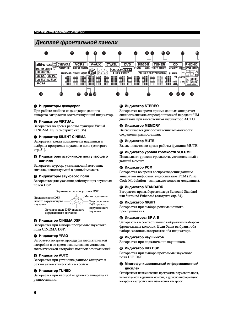
21:56
Как я настроил звук на ресивере Ямаха
01:07
YAMAHA RX-V757 Channel Home Theater Receiver
06:17
Denon avr-1911 vs yamaha rx-v757 straight/direct mode (test1)
04:10
Amplificador de audio Yamaha RX V757
01:15
Yamaha rx-v757 receiver fix
03:15
Yamaha RX-V750 AV Receiver — AV HiFi
04:07
AV-ресивер YAMAHA RX V575
Нажмите на кнопку для помощи
Найди любой мануал:
Например: Sony VGN-FW460J/T
Вы можете бесплатно скачать Руководство по эксплуатации для Yamaha RX-V550.
Также вы сможете прочесть онлайн этот документ без скачивания.
Скачать Руководство по эксплуатации для Yamaha RX-V550
Тип файла
PDF
Размер
3.06 Mb
Кол-во страниц
78
Просмотров
8609
Читать онлайн Руководство по эксплуатации для Yamaha RX-V550 (Страница 1)

Другие Стереоресиверы Yamaha RX-V550
Топ Yamaha Стереоресиверы
Ранее вы смотрели
Эта страница полезна для вас? Поделитесь ссылкой: