
Manuals Daewoo DWF-5020(P) Files size: 2175 KB, Language: English, Format: pdf, Platform: Windows/Linux, Date: 2017-03-28
On this page you can download the manuals Daewoo DWF-5020(P). We suggest you familiarize yourself with the user management, service and repair instructions.
Here you will also find a list of ordering numbers for parts and components Daewoo DWF-5020(P).
All files are provided exclusively for introductory purposes. And they are not a repair guide, but are only aimed at helping you to familiarize yourself with the principle of building a device in more detail.
The contents of the guidelines presented here require you to know the technical English language.
If you are going to download service management manual Daewoo DWF-5020(P), In other words, the manual service, you are long to possess at least minimal knowledge in the field of electronics and understanding the basic principles of the operation of electromechanical devices.
To view the manuals, you will need Adobe Acrobat Reader version 9 and above or another program for viewing PDF files.
Due to the popularity of the information presented on the site and its free provision of the final user, a convincing request to use special software products for multi-threaded download downloads.
List of manuals for Daewoo DWF-5020(P)
- Guide to use (User manual)
- Guide to service (Service manual)
- Guide to repair (Repair manual)
- The list of parts and components (PartList)
-
Repair manuals
1
Daewoo DWF-5020(P) service manual
(57 pages)
-
Type:
PDF -
Size:
891.14 KB
Preview
Daewoo DWF-5020(P) (Washing and Drying Machines) service manuals in PDF format will help to find failures and errors and repair Daewoo DWF-5020(P) and restore the device’s functionality.

DAEWOO ELECTRONICS CO., LTD.
DWF-4220 (Series)
DWF-5020 (Series)
Full-Auto Electric Washing Machine
Service Manual
612-1, AHYEON-DONG, MAPO-GU,
SEOUL, KOREA.
C.P.O. BOX 8003 SEOUL KOREA
TELEX: DWELEC K28177-8
CABLE:»DAEWOOELEC»
FAX: (02) 364-5588/5305
TEL: (02) 360/7315~7
DAEWOO ELECTRONICS CO., LTD.
S/M NO.: WF42200100 PRINTED DATE: APR. 1996

1
TABLE OF CONTENTS
1. SPECIFICATIONS……………………………………………………………………………………………………………………………………………….. 2
2. FEATURE AND TECHNICAL EXPLANATION
FEATURE OF THE WASHING MACHINE……………………………………………………………………………………………………………….3
WATER CURRENTS TO ADJUST THE UNBALANCED LOAD ………………………………………………………………………………….3
PULSATOR SYSTEM…………………………………………………………………………………………………………………………………………….4
AUTOMATIC DRAINING TIME ADJUSTMENT…………………………………………………………………………………………………………4
SOFTENER DISPENSER………………………………………………………………………………………………………………………………………..5
AUTOMATIC UNBALANCE ADJUSTMENT …………………………………………………………………………………………………………….6
CIRCULATING-WATER COURSE AND LINT FILTER……………………………………………………………………………………………….6
SYNCRONOUS MOTOR………………………………………………………………………………………………………………………………………..7
YNCRONOUS GEAR MECHANISM ASS’Y……………………………………………………………………………………………………………..8
PRINCIPLE OF BUBBLE GENERATOR…………………………………………………………………………………………………………………..8
FUNCTIONAL PRINCIPLE OF BUBBLE WASHING MACHINE …………………………………………………………………………………9
3. STRUCTURE OF THE WASHING MACHINE……………………………………………………………………………………………………… 10
4. FUNCTIONS OF THE CONTROL PANEL…………………………………………………………………………………………………………… 11
5. DIRECTIONS FOR INSTALLATION AND USE
HOW TO INSTALL THE WASHING MACHINE……………………………………………………………………………………………………….12
HOW TO CONNECT THE INLET HOSE…………………………………………………………………………………………………………………14
HOW TO GROUND THE WIRE……………………………………………………………………………………………………………………………..15
6. PROCEDURE OF FULL-AUTOMATIC WASHING………………………………………………………………………………………………. 16
7. DIRECTIONS FOR DISASSEMBLY AND ADJUSTMENT
GEAR MECHANISM ASS’Y REPLACEMENT…………………………………………………………………………………………………………18
SYNCRONOUS MOTOR AND VALVE REPLACEMENT………………………………………………………………………………………….19
BRAKE ADJUSTMENT…………………………………………………………………………………………………………………………………………19
8. TROUBLE SHOOTING GUIDE
CONCERNING WATER SUPPLY………………………………………………………………………………………………………………………….20
CONCERNING WASHING……………………………………………………………………………………………………………………………………21
CONCERNING DRAINING……………………………………………………………………………………………………………………………………22
CONCERNING SPINNING……………………………………………………………………………………………………………………………………23
CONCERNING OPERATION………………………………………………………………………………………………………………………………..24
9. PRESENTATION OF THE P.C.B. ASS’Y
CONCERNING ERROR MESSAGE……………………………………………………………………………………………………………………….25
CONFIGURATION OF FULL CIRCUITS…………………………………………………………………………………………………………………27
MINUTE EXPLANATION DIAGRAM FOR EACH PARTS…………………………………………………………………………………………28
APPENDIX
WIRING DIAGRAM………………………………………………………………………………………………………………………………………………40
PARTS LIST (THE WHOLE)…………………………………………………………………………………………………………………………………..42
PARTS DIAGRAM………………………………………………………………………………………………………………………………………………..46
P.C.B. PARTS LIST …………………………………………………………………………………………………………………………………………….. 49
CIRCUIT DIAGRAM……………………………………………………………………………………………………………………………………………..54
BARE PCB …………………………………………………………………………………………………………………………………………………………56
2
1. SPECIFICATIONS
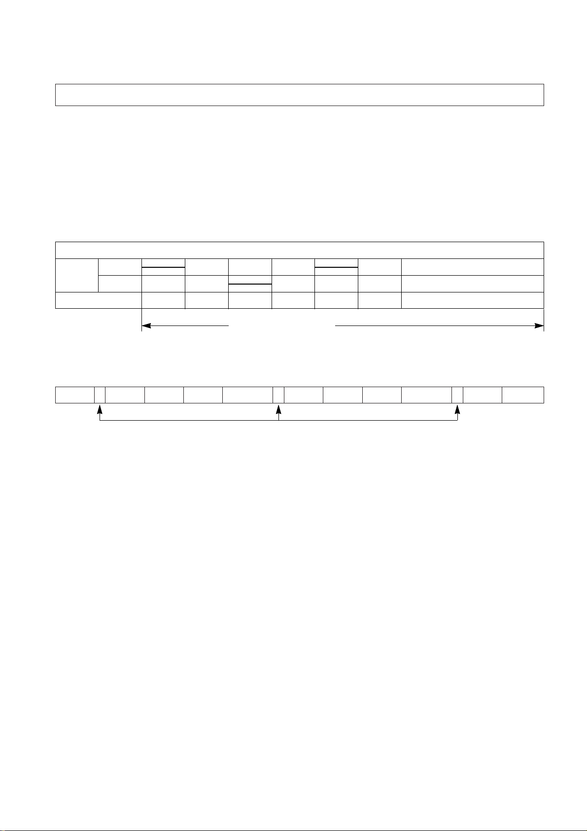
NO ITEM SPECIFICATIONS
1 POWER SOURCE
AC 220V/60Hz AC 127V/50,60Hz AC 110V/60Hz AC 220V/50Hz AC 240V/50Hz
2 POWER DWF-4220 370W 370W 370W 330W 330W
CONSUMPTION DWF-5020 430W 430W 430W 370W 370W
3
MACHINE
DWF-4220
NON PUMP: NET; 30.5kg, GROSS: 35 kg PUMP: NET; 31.5kg, GROSS; 36kg
WEIGHT DWF-5020
NON PUMP: NET; 31.5kg, GROSS: 36 kg PUMP: NET; 32.5kg, GROSS; 37kg
4 DIMENSION (WXHXD) 502X820X500
5 WASHING COURSE FULL AUTOMATIC 4 COURSES
(FUZZY, SPEED, HEAVY, WOOL)
6 WATER CONSUMPTION NORMAL 128| (131|: DWF-5020)
7 WATER LEVEL DWF-4220 HIGH (47|), MEDIUM (38|), LOW (30|), SMALL(22|)
SELECTOR DWF-5020 HIGH (48|), MEDIUM (39|), LOW (31|), SMALL(23|)
8
OPERATING WATER PRESSURE
0.3~8kgf/cm2(2.9~78.4N/cm2)
SPIN:690 (50Hz)
9 REVOLUTION PER MINUTE SPIN: 750 WASH:130 SPIN: 750 SPIN: 690
WASH: 140 SPIN: 750 (60Hz) WASH: 140 WASH: 130
WASH: 140
10 PULSATOR 5 WINGS (Ø 321mm)
11 WATER LEVEL CONTROL ELECTRONICAL SENSOR
12 OUTER CABINET SGCC
13 GEAR MECHANISM ASS’Y PLANETARY GEAR ASSEMBLY OF ENGINEERING PLASTIC
14 LINT FILTER O
15 SOFTENER INLET O
16 ALARM SIGNAL O
17 AUTO WATER SUPPLY O
18 NEW WATER FLOW WATER FLOW FOR ADJUST THE UNBALANCED LOAD
19 FUNCTION FOR BUBBLE OPTION
20 DWF-4220 4.2 kg
DWF-5020 5.0 kg
MAXIMUM
MASS OF
TEXTILE
3
FEA TURE OF THE W ASHING MACHINE
1) The first air bubble washing system in the world.
2) Quiet washing through the innovational low-noise design.
3) The wash effectiveness is much more enhanced because of the air bubble washing system.
4) The laundry detergent dissolves well in water because of the air bubble washing system.
5) The adoption of the water currents to adjust the unbalanced load.
6) One-touch operation system.
WATER CURRENTS TO ADJUST THE UNBALANCED LOAD
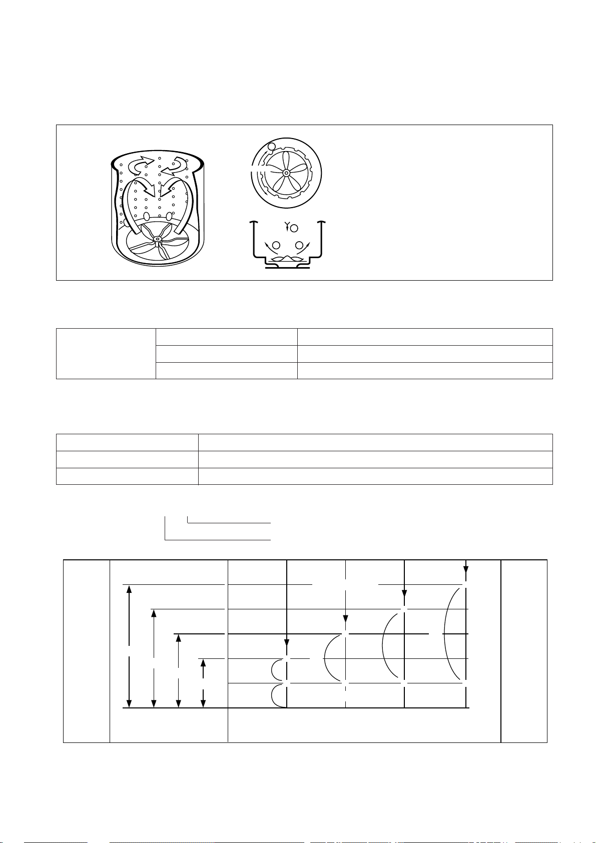
It is a function to prevent eccentricity of the clothes after washing by rotating pulsator C.W and C.C.W for 20 seconds.
WATER FLOW
NOTE: «I» mark indicates the operation of the water currents to adjust the unbalance load.
EFFECT
It reduces vibration and noise effectively during spinning.
2. FEATURE AND TECHNICAL EXPLANATION
WASH I DRAIN SPIN FILL RINSE 1 I DRAIN SPIN FILL RINSE 2 I DRAIN
…
MOTOR
C.W
SIGNAL
C.C.W
TIME (SEC.) 0.3 0.5 0.3 0.5 0.3 0.5
20 SEC. (About 13 Times)
4
PULSA TOR SYSTEM
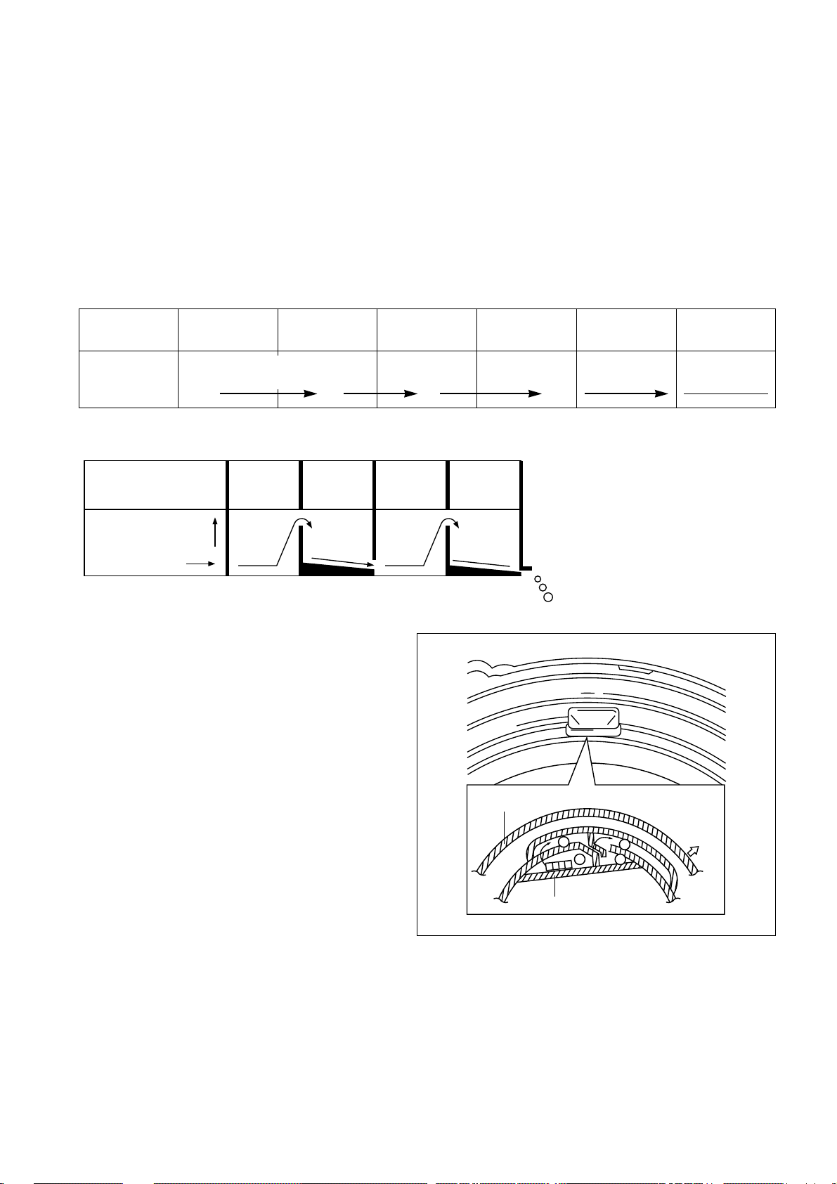
When the new shaped pulsator is rotated C.W or C.C.W at a high speed, it makes the ‘heart-shaped’ water currents as
shown below.
AUTOMA TIC DRAINING TIME ADJUSTMENT
This system adjusts the draining time automatically according to the draining condition.
FUNCTIONAL PRINCIPLE
1. The micom can remember the time from the beginning of drain to reset point when the pressure switch reaches to
«OFF» point.
2. In case of continuous draining, residual drain time is determined by micom.
Draining time as a whole=D + 60
(T sec.)
WATER CURRENTS
A Water is pushed up near the tub
wall by rotation of the pulsator.
B Water is pulled down in the middle
of the tub by rotation of the
pulsator
C Water currents is generated by
rotation of the pulsator.
Good draining The washer begins spin process after drainage.
Draining
Bad draining Draining time is prolonged.
condition
No draining Program stops and gives the alarm.
Drain Time Movement of the Program
Less than 5 minutes Continue draining.
More than 5 minutes Program stops and gives the alarm with all lamps of the «COURSE» light up.
Residual drain time.
The time remembered by micom.
DRAINING
TIME
WATER
LEVEL
T4
T3
T2
T1
TRIP POINTS
RESET POINTS
*
*
*
*
*
*
*
*
LOW MED HIGH
0
60
160
220
280
(mm)
340
60
D1
D2
D3
D4
T1=D1+60 (Sec.) T2=D2+60 (Sec.) T3=D3+60 (Sec.) T4=D4+60 (Sec.)
SMALL
5
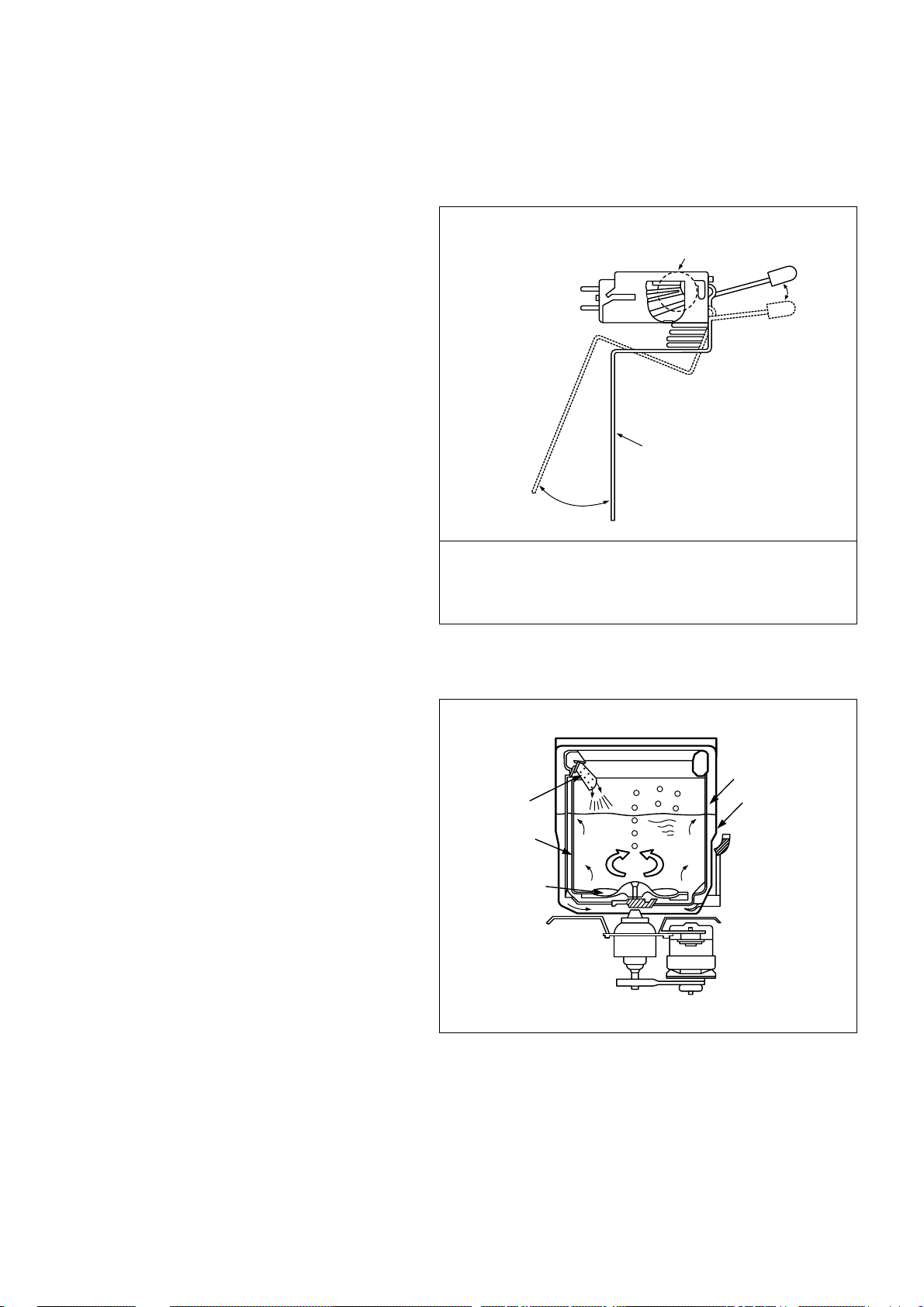
SOFTENER DISPENSER
This is the device to dispense the softener automatically by centrifugal force.
This is installed inside the Balancer Ass’y.
FUNCTIONAL PRINCIPLE
1. Softener stays in room (A) when poured into softener inlet.
2. Softener in moved from (A) to (B) by centrifugal force during intermittent spin process.
3. Softener flows from (B) to (C) during rinse process next to intermittent spin.
4. Softener in moved from (C) to (D) by centrifugal force during second intermittent spin.
After spin process is finished, the softener is added into the tub through softener outlet.
FLOW OF THE SOFTENER
FLOW OF THE SOFTENER INSIDE OF THE BALANCER
NOTE: Softener moves into the next room when r.p.m. of the tub is more than 100 r.p.m.
HOW TO CHECK MOVEMENT
Pour a reasonable amount of «MILK» into softener
dispenser and operate the washer with no load. In final
rinse cycle, make sure that the milk is added into the
tub through softener outlet.
Wash Intermittent Hold Intermittent Rinse Spin
Spin Spin
Normal Centrifugal Flow in Centrifugal Flow in
force force
Course (A) (B) (C) (D)
Room inside
ABCD
the balancer
Centrifugal force
Flowing by
weight
Balancer
Softener
B
A
D
C
outlet
Softener inlet
6
AUTOMA TIC UNBALANCE ADJUSTMENT
This system is to prevent abnormal vibration during intermittent spin and spin process.
FUNCTIONAL PRINCIPLE
1. When the door is closed, the safety switch
contact is «ON» position.
2. In case that wash loads get uneven during spin,
the outer tub hits the safety switch due to the
serious vibration, and the spin process is
interrupted.
3. In case that P.C.B. ASS’Y gets «OFF» signal from
the safety switch, spin process are stopped and
rinse process is started automatically by P.C.B.
ASS’Y.
4. If the safety switch is operated due to the
unbalance of the tub, the program is stopped and
the alarm is given.
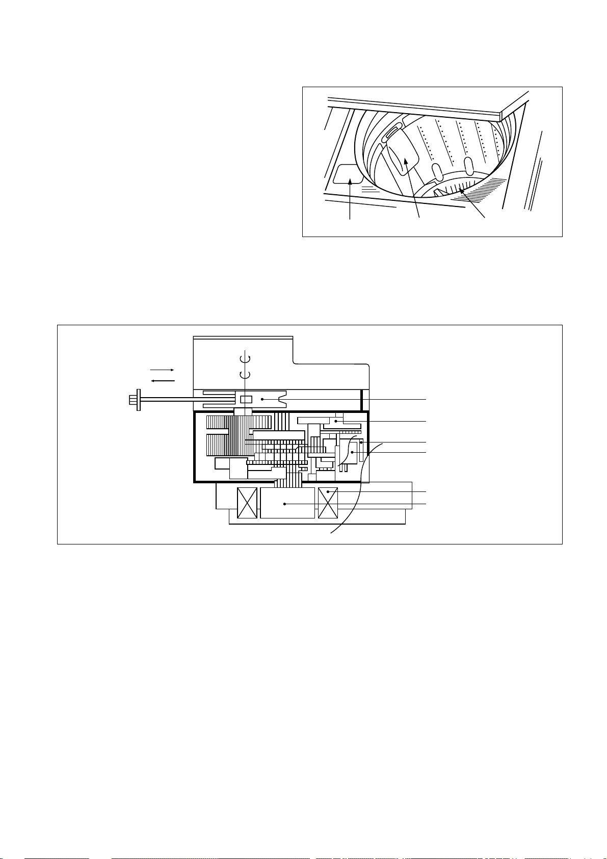
CIRCULA TING-W ATER COURSE AND LINT FILTER
CIRCULATING-WATER
The washing and rinsing effects have been
improved by adopting the water system in which
water in the tub is circulated in a designed pattern.
When the pulsator rotates during the washing or
rinsing process, the water below the pulsator vane
creates a water currents as shown in figure.
Contact of safety switch door closing
Contact lever A
Normal(ON)
Position of
unbalanced
load(OFF)
door opening
NOTE:
The alarm finished when you close the door after opening it.
Check the unbalance of the wash load and the installation
condition.
Filter
Water
channel
Pulsator
Tub
Outer tub
7
LINT FILTER
Much lint may be obtained according to the kind of
clothes to be washed and some of the lint may also
stick to the clothes.
To minimize this possibility a lint filter is provided on the
upper part of the tub to filter the wash water as it is
discharged from the water channel. It is good to use
the lint filter during washing.
HOW TO CLEAN THE LINT FILTER
1. Pull the filter frame upward.
2. Turn the lint filter inside out, and wash the lint off with water.
3. Return the filter as it was, and fix the filter frame to the slot.
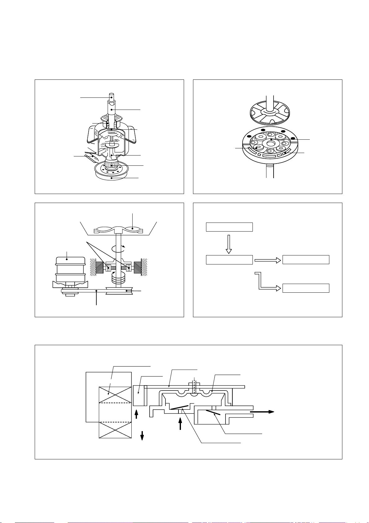
SYNCRONOUS MOTOR
STRUCTURE
FUNCTIONAL PRINCIPLE
1. When the SYNCRONOUS MOTOR connected to the power source the SYNCRONOUS MOTOR rotates and revolves
the pulley by gear assembly for reducing.
2. When the pulley is rotated, the pulley winds the wire to open the drain valve.
3. Therefore, rotation of pulley is changed to the linear moving of wire.
4. The wire pulls the brake lever of Gear Mechanism Ass’y within 5 seconds.
5. After the wire pulled, gear assembly is separated from motor and condition of pulling is held by operation of the lever.
6. When the power is turned off, the drain valve is closed because the wire returns to original position.
PulsatorFilterBleach inlet
Pull
Loosen
Pulley
Lever
Inductive ring
Magent
Coil of motor
Magnet of motor
8
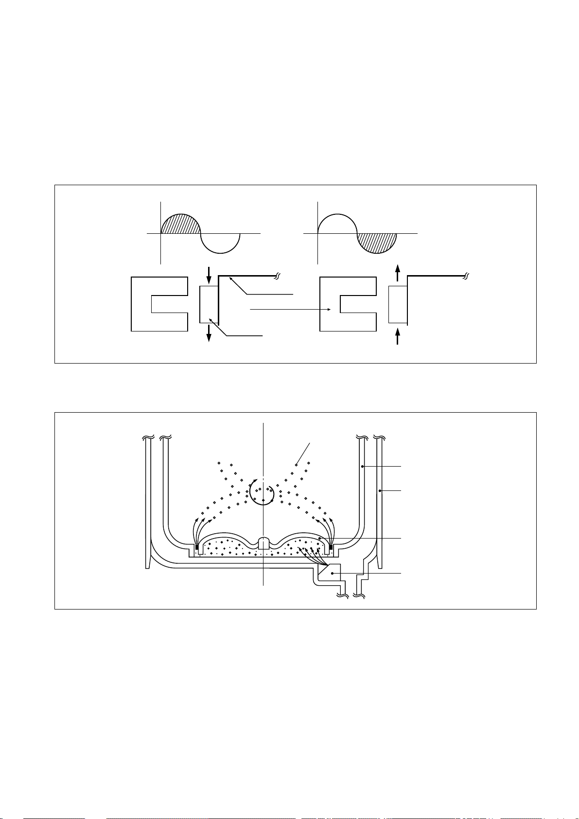
GEAR MECHANISM ASS’Y
The proper water currents is made by the rotation of pulsator at a low speed to prevent the damage to the small sized
clothes.
PRINCIPLE OF BUBBLE GENERA TOR
STRUCTURE
Pulsator shaft
One clutch bearing
Brake lever
Spinner shaft
Planetary gear
Clutch spring
Clutch boss
Spinner pulley
Sun gear
Planetary gear
Pulsator
Motor
Internal gear
Planetary
Motor
V.belt
1 revolution
5 revolutions
Spinner
pulley
Bobbin & coil
Magnet
Trans core
Armature
V.BELT
Spinner Pulley
Bellows
Planetary
gear
1/5.0
Directly
Air out hole
Pulsator
Tub
Air
Air
Air in hole
Protector A
Protector B
9
PRINCIPLE OF INTAKE & OUTLET OF THE AIR
INTAKE : ARMATURE moves up, and BELLOWS inhales the air. At the same time, protector B is open and A is close.
OUTLET: ARMATURE moves down, and BELLOWS exhausts the air. At the same time, protector B is close and A is
open.
FUNCTIONAL PRINCIPLE OF TRANS & MAGNET
• The phase of A.C electric power changes to 60 cycle/second.
• The magnetic pole of trans core is changed by the change of the phase of A.C electric power.
• The core repeats push and pull (3600 times/min.) of the armature magnet.
FUNCTIONAL PRINCIPLE OF BUBBLE WASHING MACHINE
ACROSS SECTION
FUNCTIONAL PRINCIPLE
Bubble generator supplies the air from the bottom of outer tub to the inner space of pulsator, the air is dispersed by the
rotation of pulsator. Air-bubble is created by the centrifugal force, and rises up.
A.C A.C
N
S
NS
Magnet
Leaf spring
Trans core
S
N
NS
Air bubble
Tub
Outer tub
Pulsator
Nozzle
10
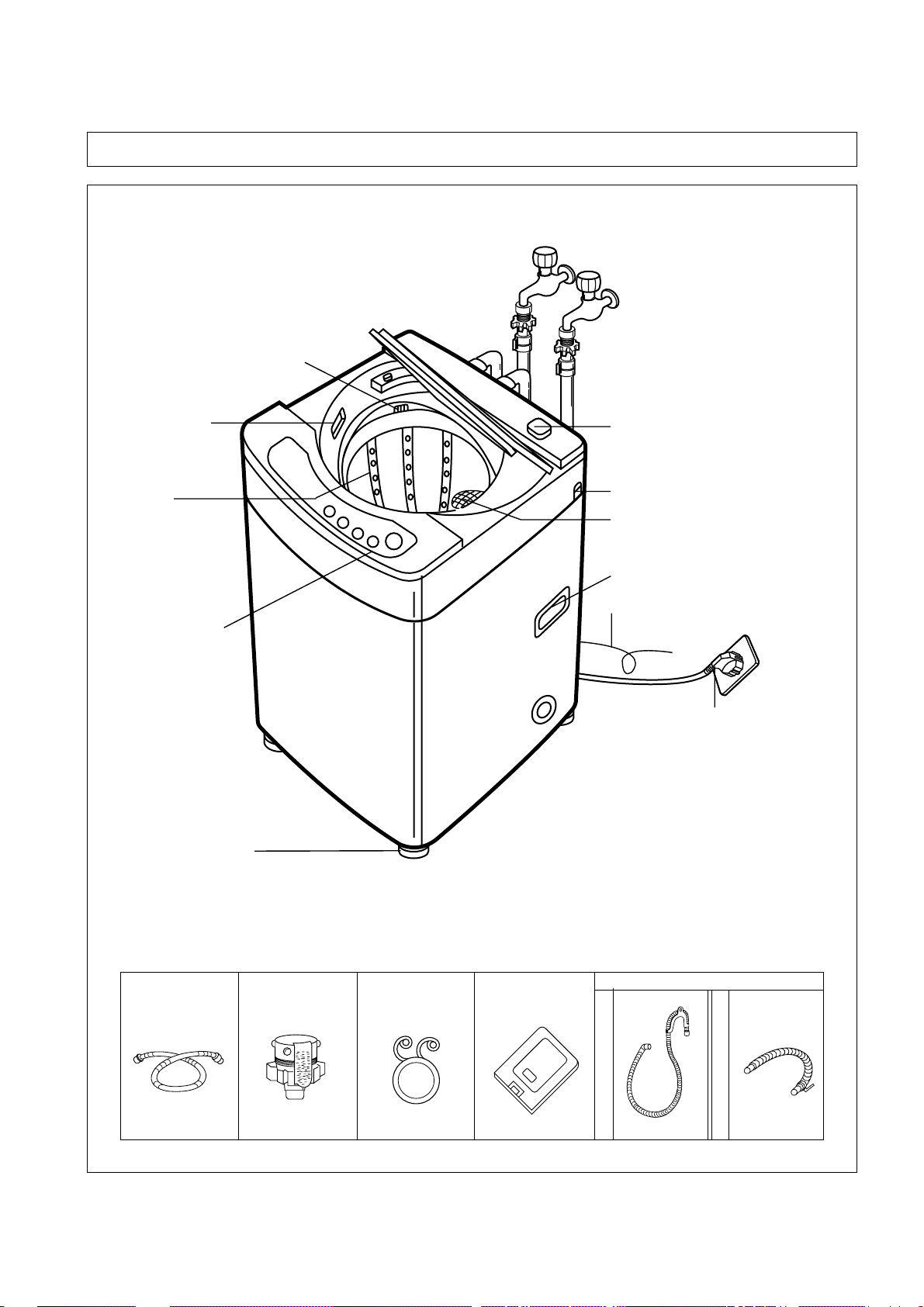
3. STRUCTURE OF THE WASHING MACHINE
Inlet Hose (COLD)
Inlet Hose
(HOT) [Option]
Water Tap Adapter
(COLD)
Water Tap Adapter
(HOT) [Option]
In case of screw-shaped inlet
hoses water tap adapters will
not be provided.
Drain Hose
Clamp
Under Base
Cover [Option]
Drain Hose
Pump Model
Non-Pump Model
• SOFTENER INLET
Pour softener into the
softener inlet just before
wash and it will be added
into the tub automatically
just before the final rinse.
• BLEACH
INLET
• TUB
• CONTROL
PANEL
• ADJUSTABLE
LEG
• POWER SWITCH
• HOOK HOLE
• LINT FILTER
• HANDLE
• GROUND WIRE
• POWER CORD
ACCESSORIES

11
4. FUNCTIONS OF THE CONTROL PANEL
Control Panel
It has micom sensor .
As the buttons are pressed, the lamps indicating the
selection of your desired washing program will light up.
Power Switch
• Press this switch to turn
the power ON or OFF.
• After turning off the power,
wait for more than 3
seconds and then turn it
on again.
Temperature Selection
Button
• This button is used to
select the water
temperature according to
the clothes being washed.
• Press this button until your
desired temperature
indicator light comes on,
and it will repeat following
signs:
COLD ¤AWARM ¤AHOT
Water Level Selector
• This selector is used to select the
washing water level according to
the size of the wash load.
Start/Hold Button
• Press this button to begin
operation or to stop
operation temporarily.
• Operation and temporary
stop are repeated as it is
pressed.
Process Selection Button
• This button is used to select the
desired process of washing.
• If a full cycle of wash, rinse, and
spin is not desired, the desired
process can be selected by
pressing this button until your
desired process indicator light
comes on.
Course Selection Button
• This button is used to select the
washing course according to
the type of the clothes being
washed.
• You can choose one of the four
courses by pressing this button
until your desired course
indicator light comes on.
HIGH
MEDIUM
HOT
WARM
COLD
WATER TEMP.
WATER LEVEL
LOW
SMALL
FUZZY
SPEEDY
COURSE
HEAVY
WOOL
WASH
RINSE
PROCESS
SPIN
START/HOLD
12
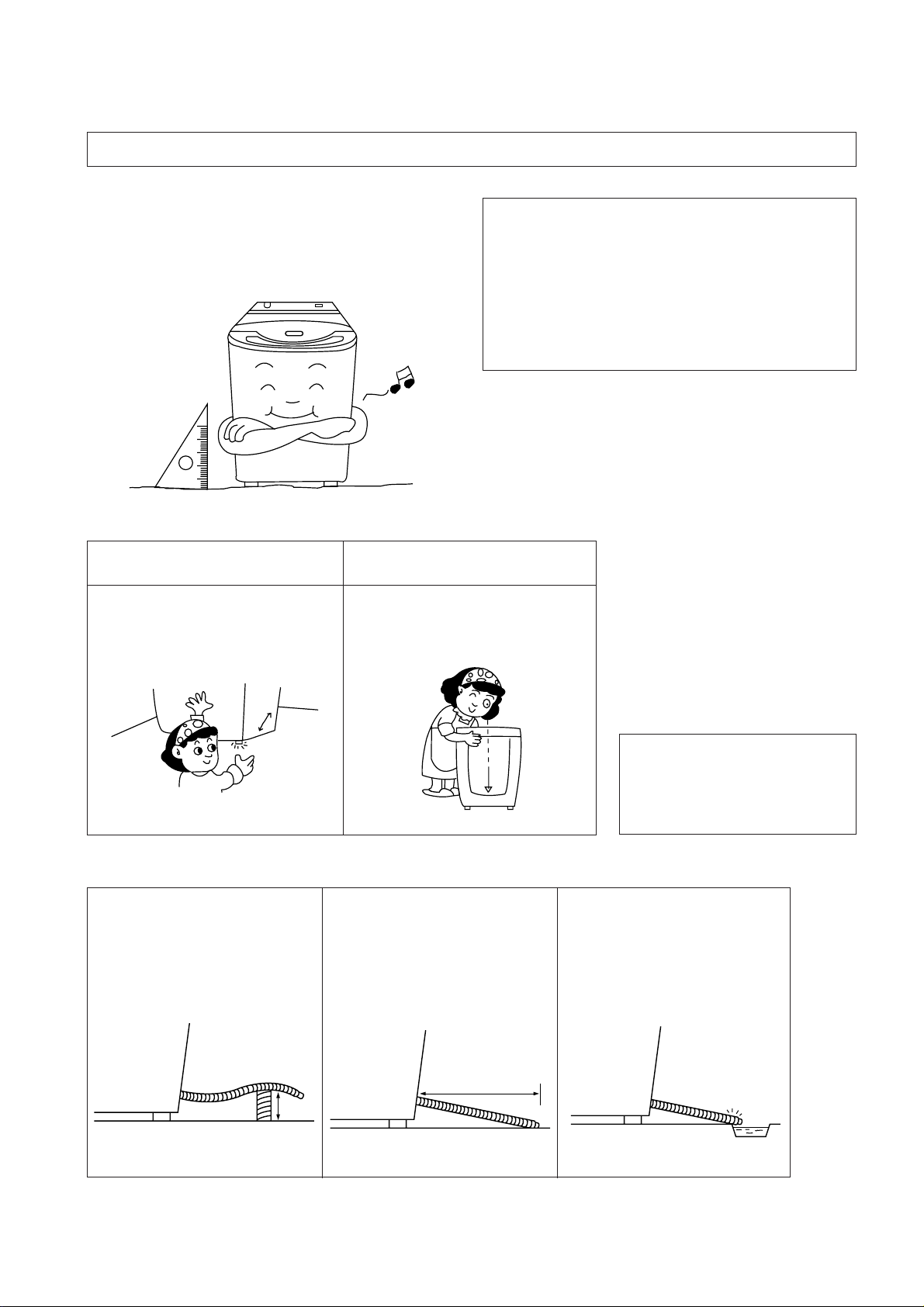
HOW TO INST ALL THE W ASHING MACHINE
Selection of the Installing Place
Install the washer on the horizontal solid floor.
If the washer is installed on an unsuitable floor, it could make
considerable noise and vibration.
How to install on an Inclined Place
5. DIRECTIONS FOR INSTALLA TION AND USE
Never install in these places.
• The place where it would be exposed to direct
sunlight.
• The place nearby a heater or heat appliances.
• The place where it would be supposed to be frozen in
winter.
• The kitchen with coal gas and a damp place like a
bathroom.
1. Height Setting
• After controlling the height by
turning the adjustable leg, let the
washer put down to the ground.
2.
Check the Horizontal Status
• Check the position of tub above
the center of the washer.
NOTES:
The opening must not be
obstructed by carpeting when
the washing machine is installed on a carpeted floor.
• The proper installation of the washing machine can
increase the wash effectiveness and the life of it.
If the washer is installed on an inclined floor, it could make considerable noise
and vibration and could cause a malfunction.
Use the height adjust rubber to adjust the washing machine so that it sits
properly.
In case that it goes over a
doorsill.
Don’t let the height of the
drain hose exceed 20cm
from the gound.
Installing the Drain Hose [Non-pump Model]
¡
™
In case of extending the drain
hose.
Don’t let the total length
exceed 3m.
Be careful that the end of the
drain hose is not immersed
in water.
13
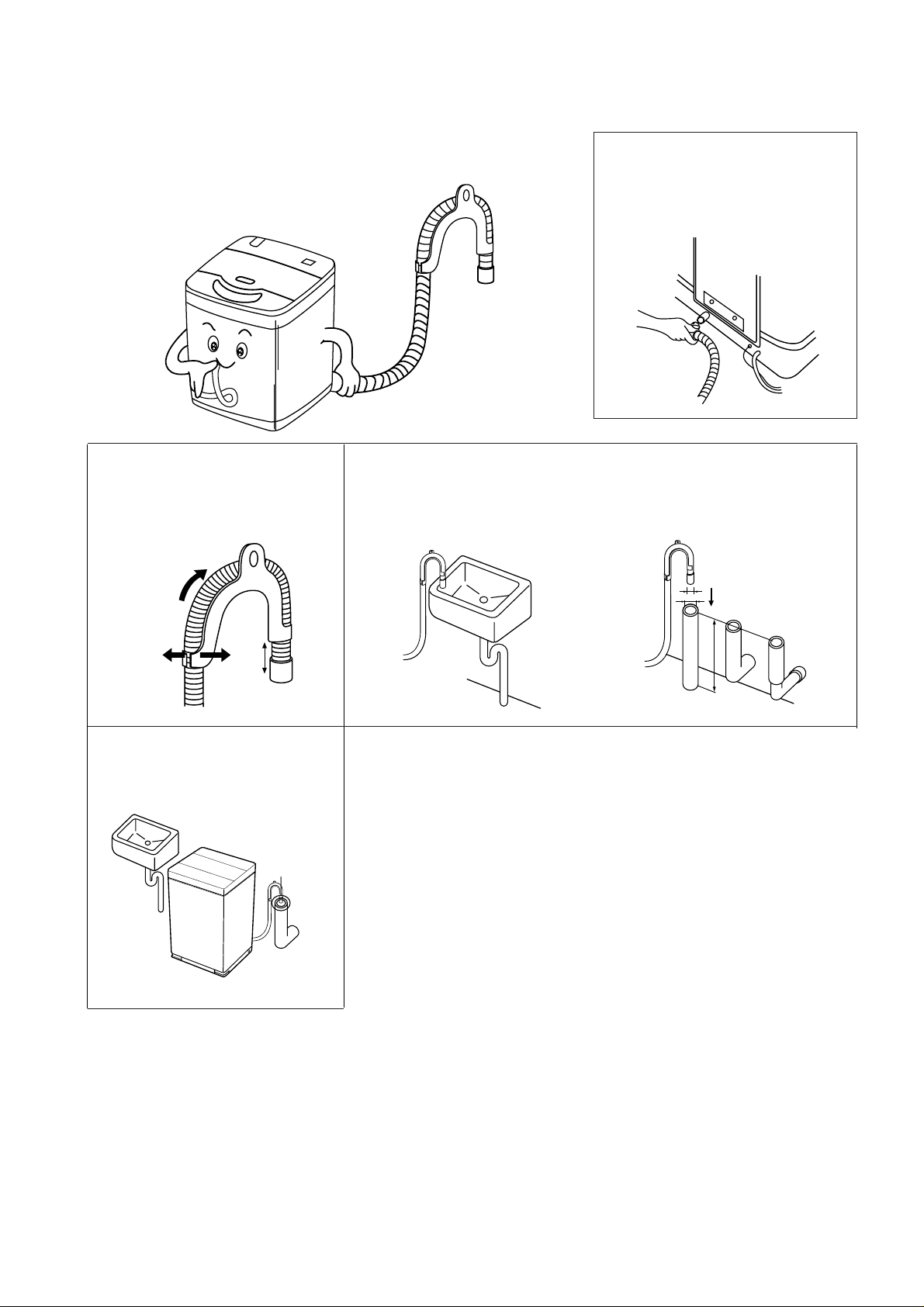
Installing the Drain Hose [Pump Model]
Never forget to install drain hose before operating this
washing machine. The packing box opened, there are a
drain hose, a clamp, and a hose fixture.
Attach the hose guide, included
in the accessory kit, to guide
the drain hose over the tub or
standpipe.
PULL HOSE
THROUGH
55mm
FLEX HOSE
GUIDE
APART
Hook the drain hose to the
edge of the tub, paying
attention that there are no
bends or constractions along
the drain hose.
Or, connect the drain hose to a
standpipe of a diameter greater than
that of the drain hose and at a height
of min. 70cm.
Position the washing machine
next to the wall.
NOTES:
1. Let the highest point of the drain hose be more than 1m above the floor.
If not so, the water in the washer could be drained during operation
2. Be sure that the height of the drain hose must be less than 1.5m above the floor.
If not so, the water in the washer could not drain.
3. The hose guide MUST be fitted to the drain hose. The drain hose sould not extend more than 55mm from the end of
the hose guide. This is to prevent ‘SYPHONING’.
If necessary the drain hose can be trimmed to length.
Connect the drain hose to the
drain outlet at the rear side of
the washing machine, and
fasten it tightly with the clamp
supplied.
¡
™
¢
£
14
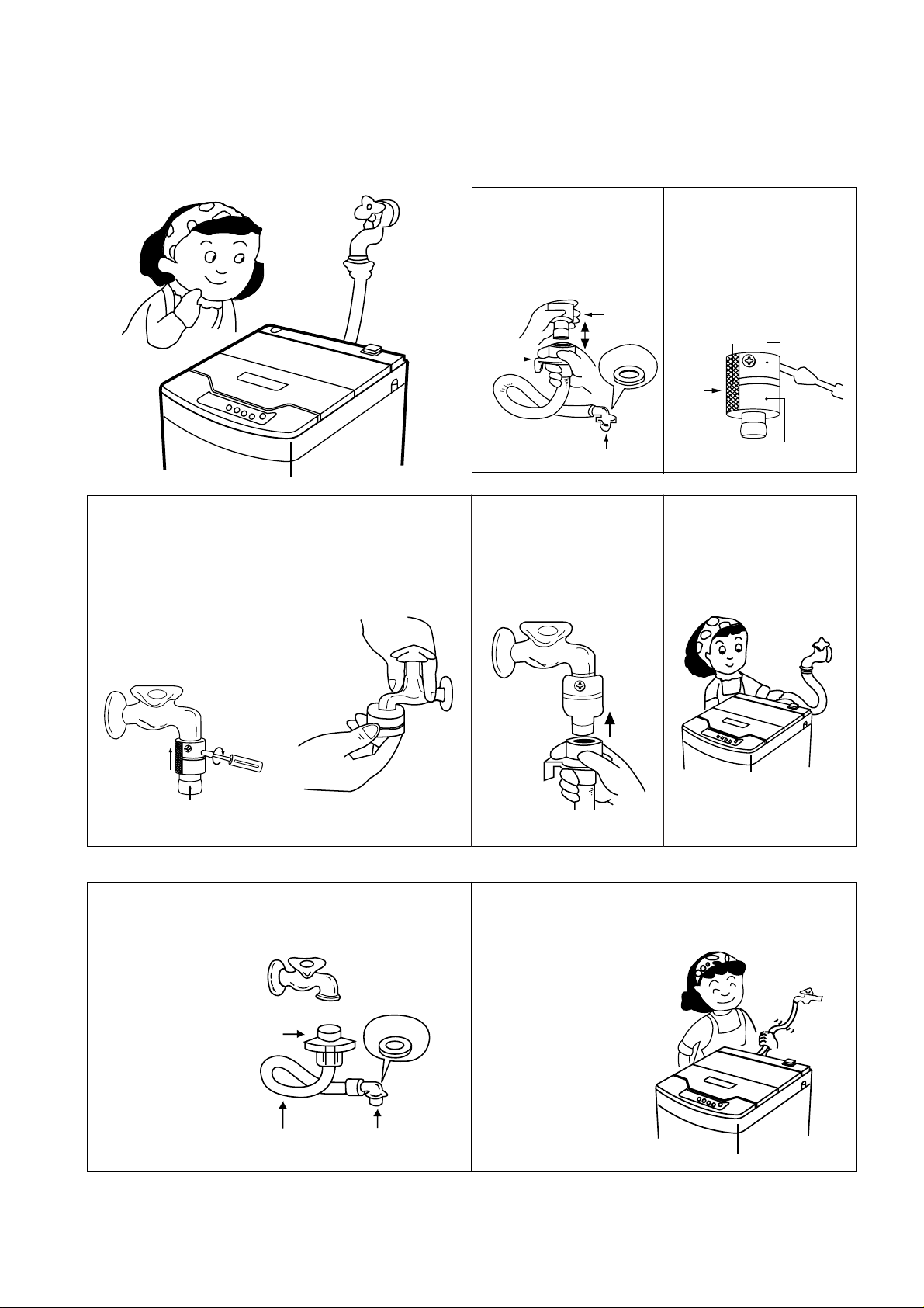
HOW TO CONNECT THE INLET HOSE
In Installing the Inlet Hose
¶
Connect the inlet
hose to the water tap
by screwing the
connector D tightly.
Connector D
Connector C
Rubber
Packing
Hose
™
Connect the connector C of the inlet hose to the
water inlet of the
washer by turning
it clockwise to be
fixed tightly.
• Please check the
rubber packing
inside the connector
C of the inlet hose.
™
Loosen the four
screw at the water
tap adapter, but
don’t loosen the
screws until they are
separated from the
water tap adapter.
Connector A
Tape
Connector B
Tap
Adapter
∞
Connect the inlet
hose to the water tap
adapter by pulling
down the collar of
the hose end.
§
Connect the connector C of the inlet
hose to the water inlet
of the washer by
turning it clock-wise
to be fixed tightly.
• Please check the rubber
packing inside the
connector C of the inlet
hose.
For Screw-Shaped Tap
¡
Pull down the collar
of the inlet hose to
separate it from the
water tap adapter.
£
Connect the water
tap adapter to the
water tap, and tighten
the four screws
evenly while pushing
up the adapter so that
the rubber packing
can stick to the water
tap tightly.
¢
Remove the tape,
and screw connector
B into connector A
tightly.
Collar
Water Tap
Adapter
Rubber
packing
Connector C
15
HOW TO GROUND THE WIRE
Grounding Method
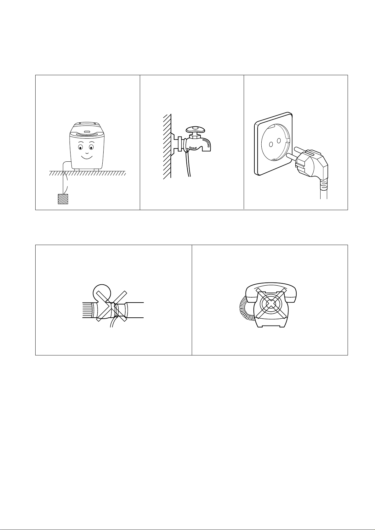
• If your water tap or water pipe is
not made of metal, connect the
ground wire to a copper plate or a
metal rod and bury it in the earth.
* It is of no use connecting the
ground wire to the water pipe
made of plastic.
• If both your water tap and water
pipe are made of metal, connect
the ground wire to the base of
the water tap.
• In case of using 3-core cord,
there is no need for grounding.
• Never connect it to a gas pipe because of danger of a
explosion.
• Never connect it to a telephone wire or a
lightning rod because it is very dangerous at a
thunderbolt.
Never Connect the Ground Wire to Such a Thing
Gas Pipe
Telephone Wire
16
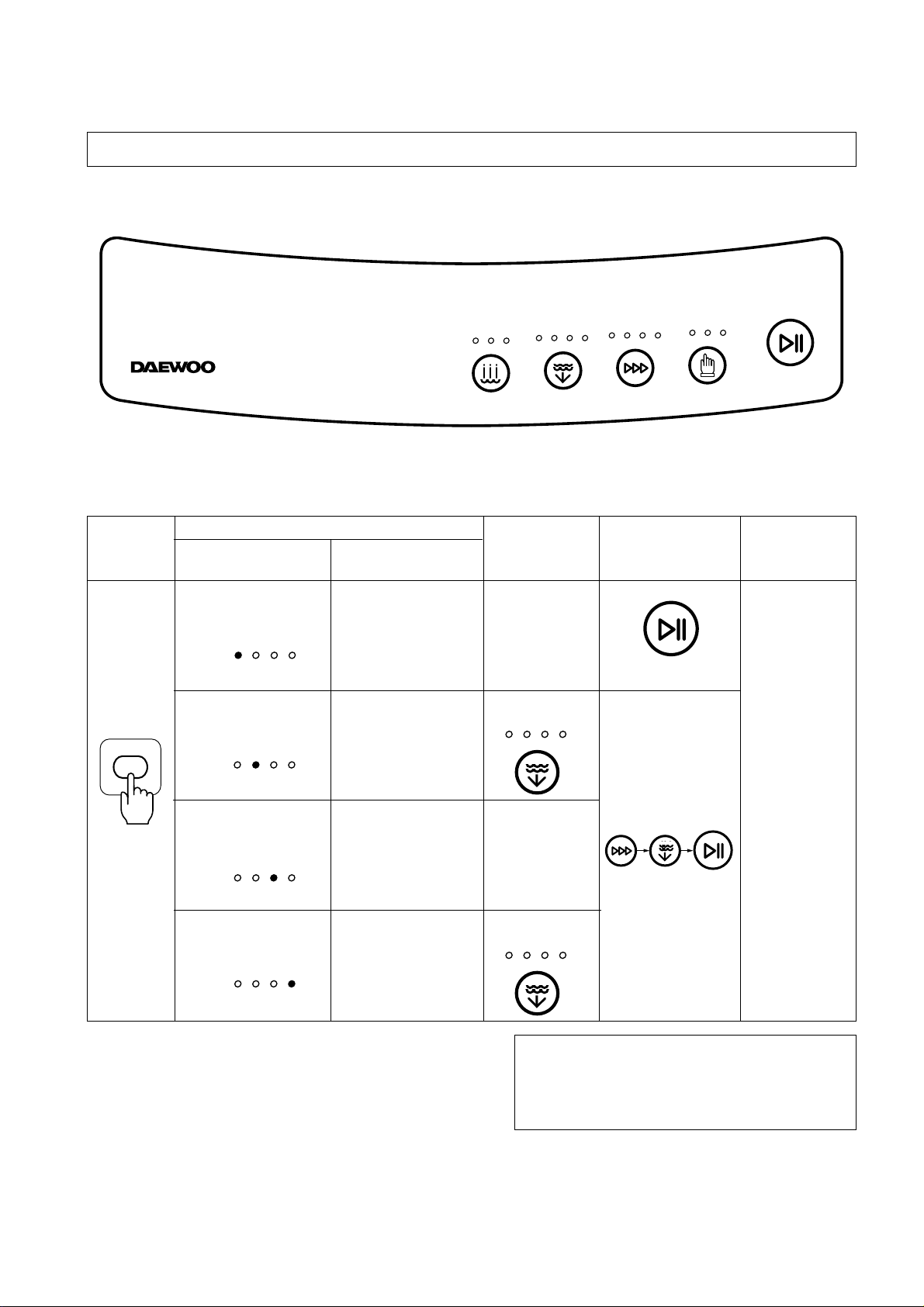
6. PROCEDURE OF FULL-AUTOMATIC WASHING
Full Automatic Course
Fuzzy General clothes
Course
Speed Lightly stained
Course clothes: under-
wear, T-shirts,
Y-shirts, etc..
Heavy Heavily stained
Course clothes: blue-jean,
climbing clothes,
ruck-sack, sports
wear, etc..
Wool Delicate clothes:
Course Sweater, silk,
lingerie, etc.
After Operation is finished
• Close the water tap, and disconnect the inlet hose if
necessary.
• Turn off the power, and disconnect the power cord from
the electric outlet, being sure to take hold of the plug.
• Clean the lint filter.
Pressing
the Power
Switch
Selecting
Water level
• The Water
level is
selected
automatically
• The Water
level is fixed
to «HIGH»
Selecting Course
Kinds of the
Course
Clothes
End of Washing
It is informed
by buzzer.
Procedure to
Press the Button
COURSE
START/HOLD
WATER LEVEL
COLD
HIGH
WATER LEVEL
HOT
WARM
WATER TEMP.
MEDIUM
LOW
SMALL
FUZZY
SPEEDY
COURSE
HEAVY
WOOL
WASH
RINSE
PROCESS
SPIN
START/HOLD
START/HOLD
COURSE
WATER LEVEL
WATER TEMP.
PROCESS
WASH
RINSE
SPIN
HOT
WARM
COLD
HIGH
MEDIUM
LOW
SMALL
FUZZY
SPEEDY
HEAVY
WOOL
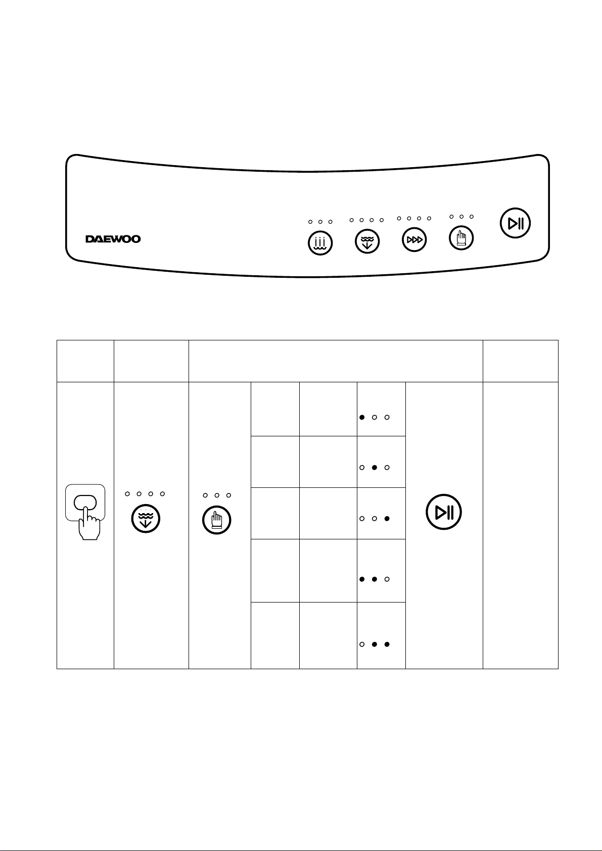
Partial Selections Among Wash, Rinse or Spin
Stage 1 Only Wash
Stage 2 Only Rinse
Stage 3 Only Spin
Stage 4 Wash and
Rinse
Stage 5 Rinse and
Spin
Pressing
the Power
Switch
Selecting
Water level
Selecting Process
WATER LEVEL
HIGH
MEDIUM
LOW
SMALL
End of
Process
It is informed
by buzzer.
Loading…
Сервис мануал и схема стиральной машины DAEWOO DWF-5020; DAEWOO DWF-4220
На английском языке, в формате PDF:
- SPECIFICATIONS
- FEATURE AND TECHNICAL EXPLANATION
- FEATURE OF THE WASHING MACHINE
- WATER CURRENTS TO ADJUST THE UNBALANCED LOAD
- PULSATOR SYSTEM
- AUTOMATIC DRAINING TIME ADJUSTMENT
- SOFTENER DISPENSER
- AUTOMATIC UNBALANCE ADJUSTMENT
- CIRCULATING-WATER COURSE AND LINT FILTER
- SYNCRONOUS MOTOR
- YNCRONOUS GEAR MECHANISM ASS’Y
- PRINCIPLE OF BUBBLE GENERATOR
- FUNCTIONAL PRINCIPLE OF BUBBLE WASHING MACHINE
- STRUCTURE OF THE WASHING MACHINE
- FUNCTIONS OF THE CONTROL PANEL
- DIRECTIONS FOR INSTALLATION AND USE
- HOW TO INSTALL THE WASHING MACHINE
- HOW TO CONNECT THE INLET HOSE
- HOW TO GROUND THE WIRE
- PROCEDURE OF FULL-AUTOMATIC WASHING
- DIRECTIONS FOR DISASSEMBLY AND ADJUSTMENT
- GEAR MECHANISM ASS’Y REPLACEMENT
- SYNCRONOUS MOTOR AND VALVE REPLACEMENT
- BRAKE ADJUSTMENT
- TROUBLE SHOOTING GUIDE
- CONCERNING WATER SUPPLY
- CONCERNING WASHING
- CONCERNING DRAINING
- CONCERNING SPINNING
- CONCERNING OPERATION
- PRESENTATION OF THE PCB ASS’Y
- CONCERNING ERROR MESSAGE
- CONFIGURATION OF FULL CIRCUITS
- MINUTE EXPLANATION DIAGRAM FOR EACH PARTS
- APPENDIX
- WIRING DIAGRAM
- PARTS LIST (THE WHOLE)
- PARTS DIAGRAM
- PCB PARTS LIST
- CIRCUIT DIAGRAM
- BARE PCB

Full-Auto Electric Washing Machine
- DWF-4220 (Series)
- DWF-5020 (Series)
Не тратьте время на поиск нужной запчасти, оформите заявку на заказ товара и наш менеджер свяжется с вами и согласует заказ.
Модель
Просьба указывать серийный номер техники, для ускорения
обработки заказа.
Запчасть
Если у вас есть Артикул (P/N) необходимой запчасти — укажите её.
Email используется для отправки уведомлений о ценах и наличии
Наша компания продает запчасти к бытовой технике уже много лет. Мы реализуем запчасти для стиральных машин Daewoo в розницу и оптом в различные регионы России и Украины. С повсеместным распространением всемирной паутины все больше людей стали делать выбор в пользу интернет-магазинов, понимая, что торговля через интернет позволяет продавцу избежать затрат связанных с арендой помещения, содержания огромного штата продавцов и т.п. Поэтому, мы предлагаем покупателям запчасти для стиральных машин по более низким ценам, нежели в обычных магазинах. Мы постоянно расширяем ассортимент запчастей, заключая договора напрямую с заводами-изготовителями.
Воспользовавшись услугами наших менеджеров, можно оперативно уточнить характеристики деталей для стиральных машин Daewoo, получить консультацию по применению, взаимозаменяемости запчасти и другую дополнительную информацию.
Для оплаты заказа предусмотрены различные возможности, удобные как частным лицам, так и организациям. Доставка возможна несколькими способами: товар может доставить наш курьер, можно воспользоваться услугами транспортных компаний, либо осуществить пересылку почтой не только в такие крупные города как Москва, Санкт-Петербург, Нижний Новгород, Екатеринбург, Казань, Самара, Новосибирск, Киев, Днепропетровск, Донецк, Харьков, Запорожье, Одесса, Львов, а и в любой уголок России и Украины.