

azur 540A/640A
Integrated amplifier / HIFI-Verstärker / Amplificateur intégré / Amplificador integrado / Amplificatore
integrato / Geïntegreerde versterker / Integreret forstærker / Встроенный усилитель
User’s manual / Bedienungsanleitung / Mode d’emploi / Manual del usuario / Manuale per l’utente /
Gebruikershandleiding / Brugermanual / Руководство для пользователя

2
Thank yyou ffor ppurchasing tthis CCambridge AAudio aazur sseries aamplifier. IIt
is tthe rresult oof oour mmost eext
ensive eever rresearch aand ddevelopment
program iin oover tthree ddecades oof pproducing hhigh qquality aaudio pproducts.
We hhope tthat yyou wwill aappreciate tthe rresults aand eenjoy mmany yyears oof
listening ppleasure.
About tthis aamplifier
The design of any purist audio amplifier is mainly centred on two main
areas, the Power Supply and the driver stage’s ability to drive the output
stage effectively. We at Cambridge Audio have researched the best
possible ways to achieve the highest performance in these areas, at a
sensible price. The Azur 540A/640A topology uses the same tried and
tested output devices that Cambridge Audio have used in previous
award winning amplifier models, but many hours of research have gone
into the study and development of the preceding stages. This driver
circuitry is essentially a matched differential input pair, loaded by a
current mirror and driven from a transient compensated current source
driving a high beta cascoded voltage gain stage. The thermally
compensated output stage is setup to inherently give optimum Class AB
conditions (for greatly reduced cross over distortion caused by dynamic
heating of the output dies). In addition the topology includes a further
improvement to the driver stage consisting of a pure class-A follower to
isolate the voltage amplifier transistors from the difficult loading of the
output transistors. This increased current drive to the output stage
combined with a novel transient feed forward circuit doubles the slew
rate to 40V/uS.
Due to critically refined circuit board layouts, careful component
placement and short signal paths the stability of these amplifiers is
extremely high which allows the compensation components to be
reduced in size. This has the effect of reducing distortion, increasing
dynamics and allowing the bandwidth to be opened up to a massive
80kHz, ideal for the new ‘better than CD’ high bandwidth sources such
as DVD-Audio and Super Audio CD.
The performance of any amplifier is limited by the dynamic abilities of its
power supply, and f or this reason Cambridge Azur amplifiers incorporat e
many features, including a low flux toroidal transformer, paralleling of
the reservoir capacitors and careful use of bypass capacitors, to allow
the instantaneous clean delivery of charge whenever it is needed. This
ensures an open and natural sound being reproduced and ensures a
positive response to any dynamics or sudden transients in the signal
being reproduced.
Particular attention has also been paid to the quality of the passive
components which have been carefully chosen for their sonic benefits.
The Azur 640A in addition uses high grade Polypropylene signal bypass
capacitors to improve signal flow and dynamics.
The Cambridge Audio Azur 540A and 640A amplifiers also incorporate
tone controls, which may be switched out of circuit in ‘direct’ mode for
the shortest and therefore purest signal path. Other features include
24k gold plated phono sockets, dual tape loops, pre amp output, a
headphone socket and a secondary set of high level loudspeaker
terminals.
An important feature which has been included as standard on both the
540A and 640A is the new innovative Cambridge Audio designed CAP5
protection system. This consists of a microprocessor which constantly
monitors the amplifier providing comprehensive protection against a
variety of possible faults. This has been achieved without adding any
active circuitry into the signal path to degrade the sound or the dynamic
abilities of the amplifier.
INTRODUCTION

540A/640A Integrated amplifier
3
Cambridge Audio has built up an extensive knowledge base due to
meticulous listening and tweaking. This attention to detail results in
amplifiers that are totally convincing in the reproduction of both tonal
colour and dynamic contrast, deliver a vibrant and fluid performance
with music of all types and are extremely musically involving.
To get the absolute best from this equipment we would encourage you
to use only high quality source components. Of course we particularly
recommend tuners and digital equipment from the Cambridge Audio
range, all of which have been designed to the same exacting standards
as our amplifiers. Many types of loudspeakers were used in the
development of these amplifiers to ensure maximum compatibility with
a wide variety of designs.
Interconnects and speaker cables are also something that shouldn’t be
overlooked. Please do not compromise your system’s performance by
using poor quality cables to connect source components to your
amplifier or the amplifiers output to your loudspeakers. A system is only
as good as its weakest link. For this reason we do not include cheap
«freebie» cables with any of our products. Your dealer can supply good
quality Cambridge Audio interconnects and Mordaunt Short/Gale
loudspeaker cables that will make a noticeable improvement to the
sound quality of your system.
Now wwe iinvite yyou tto ssit bback, rrelax aand eenjoy!
Matthew Bramble
Technical Director
Introduction…………………………………………………………………………………….2
Safety precautions…………………………………………………………………………..4
Installation………………………………………………………………………………………5
Rear panel connections …………………………………………………………………..6
Connecting…………………………………………………………………………………….. 8
Operating instructions……………………………………………………………………10
CAP5 — Five way protection system…………………………………………………..12
Troubleshooting……………………………………………………………………………..14
Specifications………………………………………………………………………………..14
Limited warranty……………………………………………………………………………15
CONTENTS
4
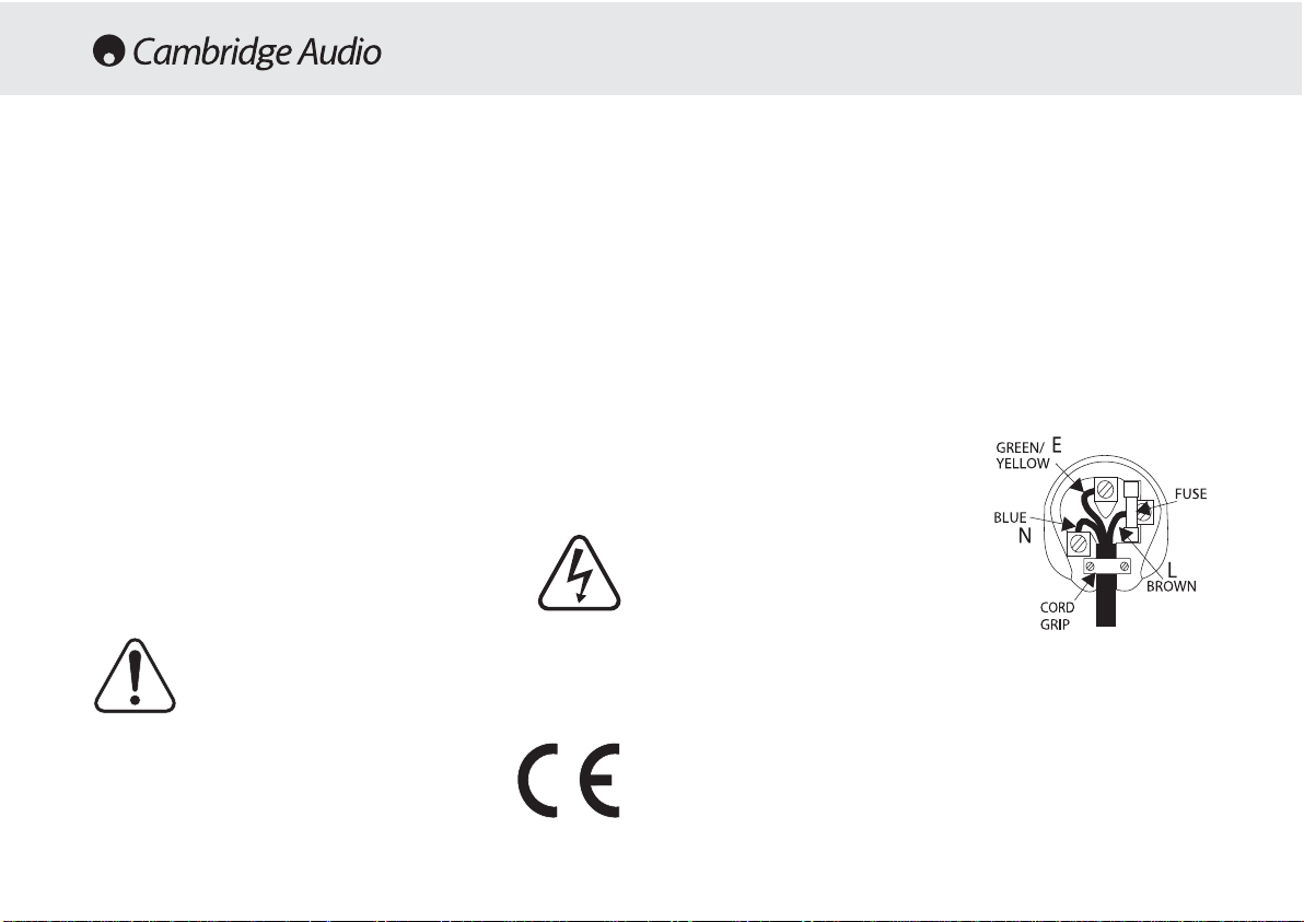
Plug ffitting iinstructions ((UK only)
The cord supplied with this appliance is factory fitted with a 13A mains plug fitted
with a 3A fuse inside. If it is necessary to change the fuse, it is important that a 3A
one is used. If the plug needs to be changed because it is not suitable for your
socket, or becomes damaged, it should be cut off and an appropriate plug fitted
following the wiring instructions below. The plug must then be disposed of safely,
as insertion into a 13A socket is likely to cause an electrical hazard. Should it be
necessary to fit a 3-pin BS mains plug to the power cord the wires should be fitted
as shown in this diagram. The colours of the wires in the mains lead of this
appliance may not correspond with the coloured markings identifying the
terminals in your plug. Connect them as follows:-
The wire which is coloured BLUE must be
connected to the terminal which is marked
with the letter ‘N’ or coloured BLACK.
The wire which is coloured BROWN must be
connected to the terminal which is marked
with the letter ‘L’ or coloured RED
The wire which is coloured GREEN/YELLOW
must be connected to the terminal which is
marked with the letter ‘E’ or coloured
GREEN.
If your model does not have an earth wire,
then disregard this instruction.
If a 13 Amp (BS 1363) plug is used, a 3 Amp fuse must be fitted, or if any other
type of plug is used a 3 Amp or 5 Amp fuse must be fitted, either in the plug or
adaptor, or on the distribution board.
Checking tthe ppower ssupply rrating
For your own safety please read the following instructions carefully before
attempting to connect this unit to the mains.
Check that the rear of your unit indicates the correct supply voltage. If your mains
supply voltage is different, consult your dealer.
This unit is designed to operate only on the supply voltage and type that is
indicated on the rear panel of the unit. Connecting to other power sources may
damage the unit.
This equipment must be switched to Standby mode when not in use, unplugged if
not used for long periods of time, and must not be used unless correctly earthed.
To reduce the risk of electric shock, do not remov e the unit’s co v er (or back). There
are no user serviceable parts inside. Refer servicing to qualified service personnel.
If the power cord is fitted with a moulded mains plug the unit must not be used if
the plastic fuse carrier is not in place. Should you lose the fuse carrier the correct
part must be reordered from your Cambridge Audio dealer.
The lightning flash with the arrowhead symbol within an equilateral
triangle is intended to alert the user to the presence of uninsulated
‘dangerous voltage’ within the product’s enclosure that may be of
sufficient magnitude to constitute a risk of electric shock to
persons.
The exclamation point within an equilateral triangle is intended to
alert the user to the presence of important operating and
maintenance instructions in the service literature relevant to this
appliance.
This product complies with European Low Voltage (73/23/EEC)
and Electromagnetic Compatibility (89/336/EEC) Directives
when used and installed according to this instruction manual. For
continued compliance only Cambridge Audio accessories should
be used with this product and servicing must be referred to
qualified service personnel.
SAFETY PRECAUTIONS

540A/640A Integrated amplifier
5
Please take a moment to read these notes before installing your
amplifier, they will enable you to get the best performance and prolong
the life of the product.
The unit requires ventilation above and below. Do not situate it on a rug
or other soft surface and do not obstruct the air inlet and outlet grilles
on the underside and top cover. Do not place in an enclosed area such
as a bookcase or in a cabinet.
This unit must not be exposed to dripping or splashing water or other
liquids. No objects filled with liquid, such as vases, shall be placed on
the unit. In the event, switch off immediately, disconnect fr om the mains
supply and contact your dealer for advice.
Ensure that small objects do not fall through any ventilation grille. If this
happens, switch off immediately, disconnect from the mains supply and
contact your dealer for advice.
Do not route the power cable so that it can be walked upon or damaged
by other items near it.
Electronic audio components have a running in period of around a week
(if used several hours per day). This will allow the new components to
settle down, the sonic properties will improve over this time.
It is recommended that when bi-amping, the same type power amplifiers
are used.
This amplifier has been designed to be left in Standby mode when not
in use, this will increase the life of the amplifier (this is true with all
electronic equipment). If you do not intend to use this unit for a long
period of time, unplug it from the mains socket.
To clean the unit, wipe its case with a moist, lint-free cloth. Do not use
any cleaning fluids containing alcohol, ammonia or abrasives. Do not
spray an aerosol at or near the amplifier.
These units are not user serviceable, never attempt to repair,
disassemble or reconstruct the unit if there seems to be a problem. A
serious electric shock could result if this precautionary measure is
ignored. In the event of a problem or failure, please contact your dealer.
This unit should be installed on a sturdy, level surface. Due to stray
magnetic fields turntables should not be located nearby due to
interference.
INSTALLATION
6
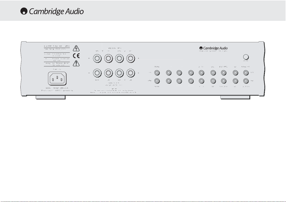
AC power ssocket
Once you have completed all connections to the amplifier, plug the AC
Power Cable into an appropriate mains socket. The amplifier is now
ready for use.
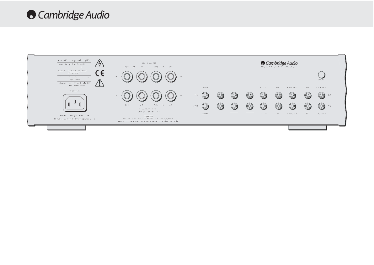
Loudspeaker cconnections
The 540A and 640A have two sets of Loudspeaker terminals on the rear
panel, speakers A and B. Speakers A are the main speaker terminals,
speakers B are the secondary switchable speaker terminals. Connect
the wires from your left channel loudspeaker to the LEFT + & — terminals,
and likewise the wires from the right channel loudspeaker to the RIGHT
+ & — terminals. In each case the red terminal is the positive output, and
the black terminal is the negative input. Care should be taken to ensure
no stray strands of wire are shorting speaker outputs together. Please
Note: TThis aamplifier hhas bbeen ddesigned ffor uuse wwith lloudspeakers tthat
have aa nnominal iimpedance oof bbe
tween 44 aand 88 oohms.
Please eensure tthat tthe sspeaker tterminals hhave bbeen ttightened
adequately tto pprovide a
a ggood eelectrical cconnection. IIt iis ppossible ffor tthe
sound qquality tto bbe aaffected iif tthe sscrew tterminals aare lloose.
Pre aamp oouts
Connect these sockets to the inputs on an external Power Amplifier(s).
Tape mmon
These sockets can be connected to a tape deck or to the analog sock ets
on a MiniDisc or CD recorder. Connect an interconnect cable from the
recorder’s Line Out sockets to the amplifier’s Tape Monitor sockets. This
Please ensure that loudspeaker terminals are fully tightened
Veuillez s’assurer que les bornes de l’enceinte sont entierement serreesVeuillez s‘assurer que les bornes de l’enceinte sont entierement serrees
www.cambridge-audio.co.uk
Designed and Engineered in London, England
Risque de choc electrique
Vorm offnen des geratesVorm offnen des gerates
azur 640A Integrated Amplifier
zur 640A Integrated Amplifie
Power Rating:
ax Power Consumption
isk of electric shoc
aution
o not ope
Avis
Risque de choc electrique
Ne pas ouvrir
Achtung
etzstecker ziehen
ower A
ww.cambridge-audio.co.u
anufactured in an
SO900
615W
approved facility
ight
ight
A
oudspeaker Terminals
lease ensure that loudspeaker terminals are fully tightened
eft
eft
mpedance 4 — 8 ohms
Important
mpedance 4 — 8 ohms
ight
ight
Left
eft
esigned and Engineered in London, England
Groun
re-Out
ape In
ec Out 1
eft
ape InRec Out 1Rec Out
re-Out
AV / MD
Rec Out
AV / MD
uner / DAB
Tuner / DAB
D
CDCDAux / Phon
ux / Phono
eft
ight

540A/640A Integrated amplifier
7
monitor doubles up as the standard tape/recording medium input.
Note: WWhen cconnecting aa ssource ccomponent tthat hhas bboth aan iinput aand
output ii.e. aa ttape rrecorder, tthe o
output oof wwhich sshould aalways bbe
connected tto tthe TTape MMon iinput. TThis wwill eeliminate hhowlround iif tthe
wrong iinput cchannel iis sselected.
Tape oout
These sockets can be connected to a tape deck or to the analog sock ets
on a MiniDisc or CD recorder. Connect an interconnect cable from the
Tape Out sockets of this amplifier to the recorder’s Line In. Please note
that this unit has two tape loops which have identical outputs.
CD/Tuner/DVD/AV/MD iinput ssockets
These inputs are suitable for any ‘line level’ source equipment such as
CD players, DAB or FM/AM tuners etc.
Aux/Phono iinput ssockets
Connect any ‘line level’ source equipment t o these sockets i.e. CD player
or DAB tuner. Alternatively this particular input can be converted to a
dedicated turntable if desired although to do this a Cambridge Audio
PM01 Phono Module must be fitted. Please contact your Cambridge
Audio dealer who can supply and install a phono stage to your amplifier.
These iinputs aare ffor aanalog aaudio ssignals oonly. TThey sshould nnot bbe
connected tto tthe ddigital ooutput oo
f aa CCD pplayer oor aany oother ddigital ddevice.
Ground cconnection
If you are connecting a turntable to your amplifier then its ground wire
should be attached to this point
8
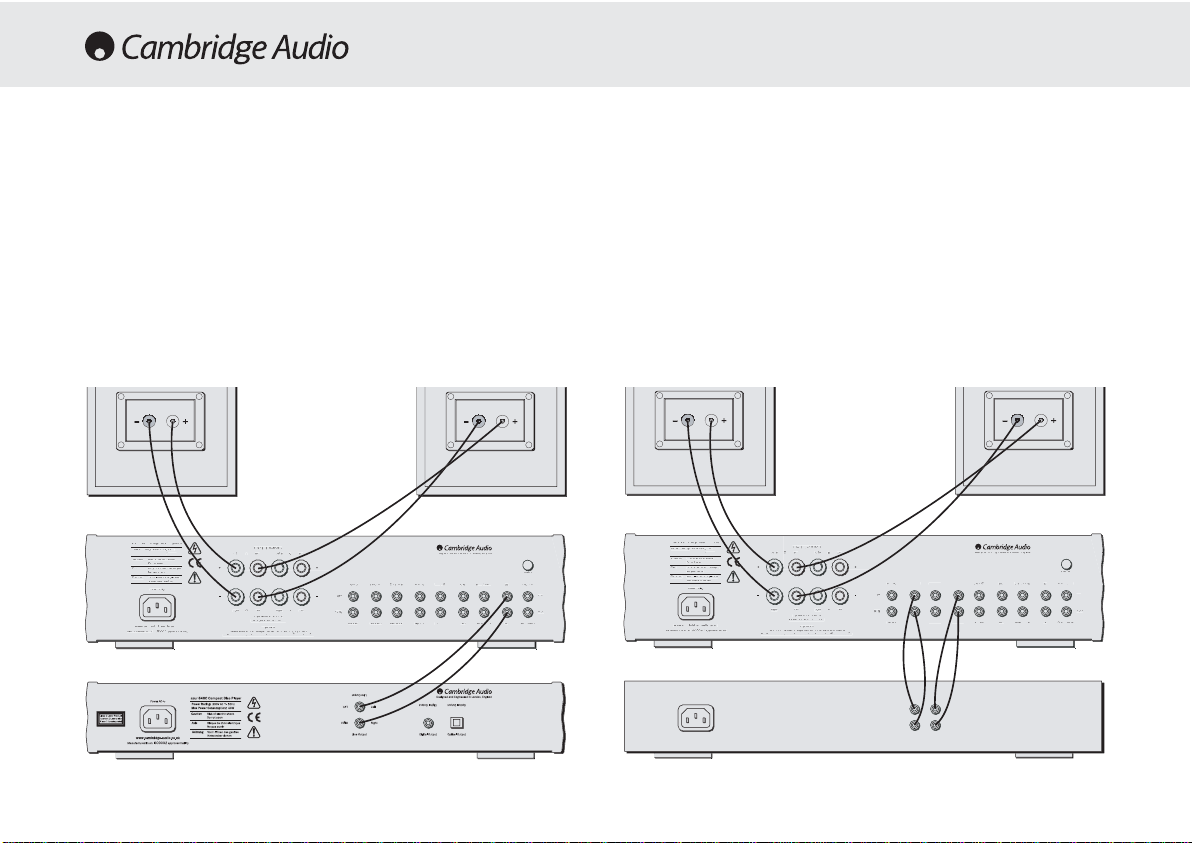
When designing our amplifiers we have tried to include features that
allow you to connect your system in various ways. The inclusion of
features such as PRE-OUT and SPEAKER B connections mean that you
can configure your system depending on your requirements. The
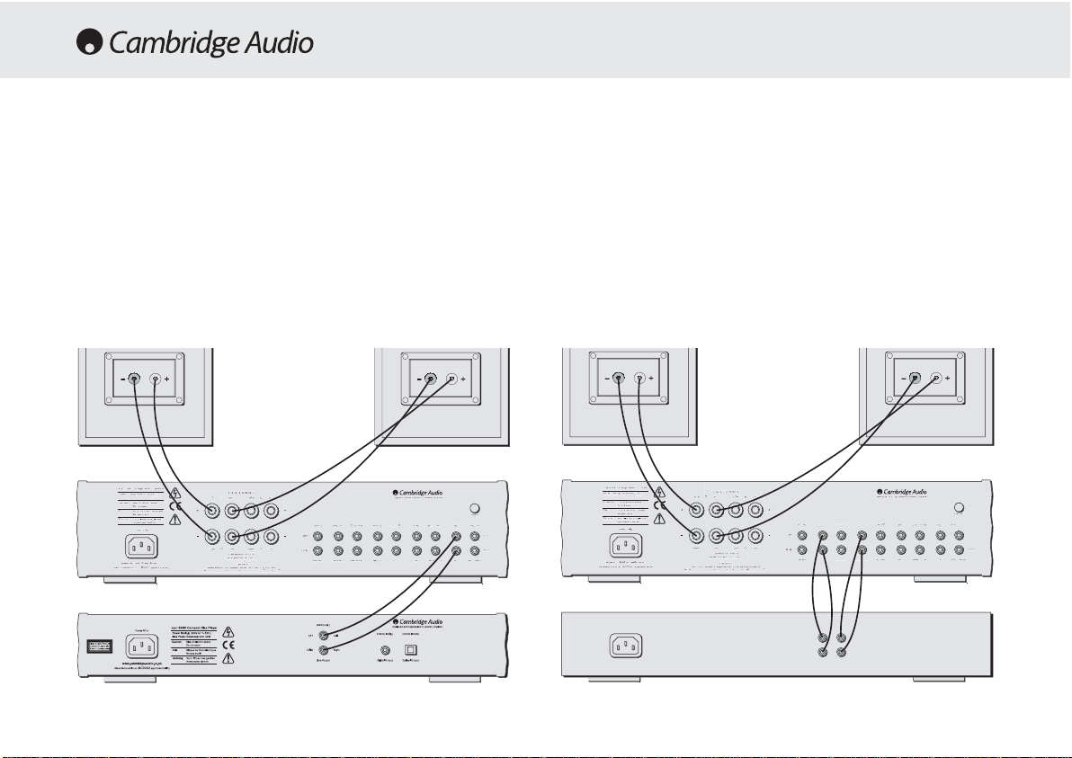
following diagrams are designed to make connection easy.
Basic cconnection
The following diagram shows the basic connection of your amplifier to a
CD player and a pair of loudspeakers.
Tape cconnection
The following diagram shows how to connect the amplifier to a tape
recorder or other source with a record and monitor connection.
Please note that either of the tape loop outputs can be used (as they are
both the same).
CONNECTING
Please ensure that loudspeaker terminals are fully tightened
Veuillez s’assurer que les bornes de l’enceinte sont entierement serrees
Veuillez s’assurer que les bornes de l’enceinte sont entierement serrees
www.cambridge-audio.co.uk
Designed and Engineered in London, England
Risque de choc electrique
azur 640A Integrated Amplifier
Please ensure that loudspeaker terminals are fully tightened
Veuillez s’assurer que les bornes de l’enceinte sont entierement serrees
Veuillez s’assurer que les bornes de l’enceinte sont entierement serrees
www.cambridge-audio.co.uk
Designed and Engineered in London, England
Risque de choc electrique
azur 640A Integrated Amplifier
zur 640A Integrated Amplifier
Power Rating:
ax Power Consumption
isk of electric shock
o not ope
Risque de choc electriqu
as ouvrir
tun
etzstecker ziehe
ower AC
ww.cambridge-audio.co.uk
anufactured in an
ISO900
615W
approved facilit
Impedance 4 — 8 ohms
eft
Right
A
t
ight
Left
ight
Impedance 4 — 8 ohms
Loudspeaker Terminals
Important
lease ensure that loudspeaker terminals are fully tightened
eft
re-Out
eft
ight
ec Out
Pre-Ou
esigned and Engineered in London, Englan
ec Out 1
ape I
ec Out
ec Out
ape I
AV / MD
roun
Tuner / DAB
Aux / Phono
Tuner / DAB
ight
CD
ux / Phon
zur 640A Integrated Amplifier
Power Rating:
ax Power Consumption
615W
isk of electric shock
o not ope
Risque de choc electriqu
as ouvrir
tun
etzstecker ziehe
ower AC
ww.cambridge-audio.co.uk
anufactured in an
ISO900
approved facilit
Impedance 4 — 8 ohms
eft
Right
t
ight
Left
ight
Impedance 4 — 8 ohms
Loudspeaker Terminals
Important
lease ensure that loudspeaker terminals are fully tightened
eft
re-Out
eft
ight
ape In
Pre-Ou
ape In 1
ec Out 1
ec Out 1Rec Out
esigned and Engineered in London, Englan
Rec Out
AV / MD
roun
Tuner / DAB
Aux / Phono
Tuner / DAB
ight
CD
ux / Phon
540A/640A Integrated amplifier
9
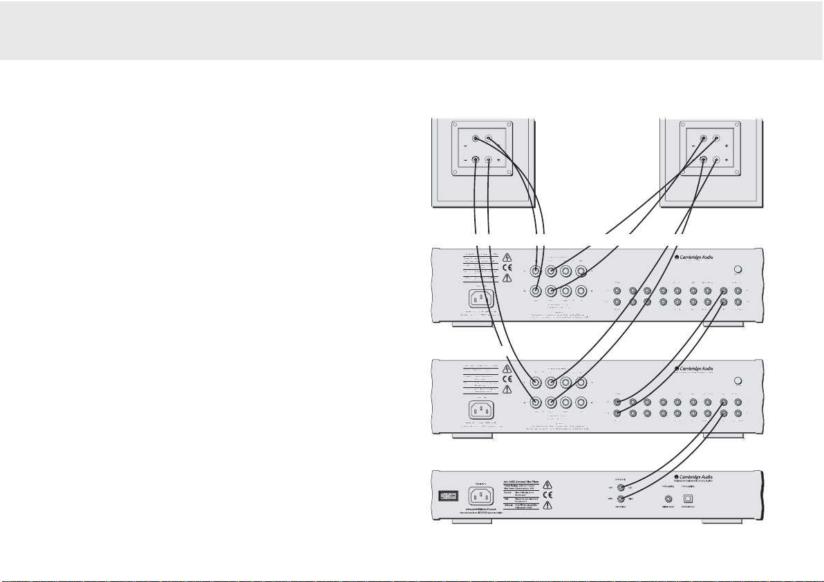
Bi-aamping
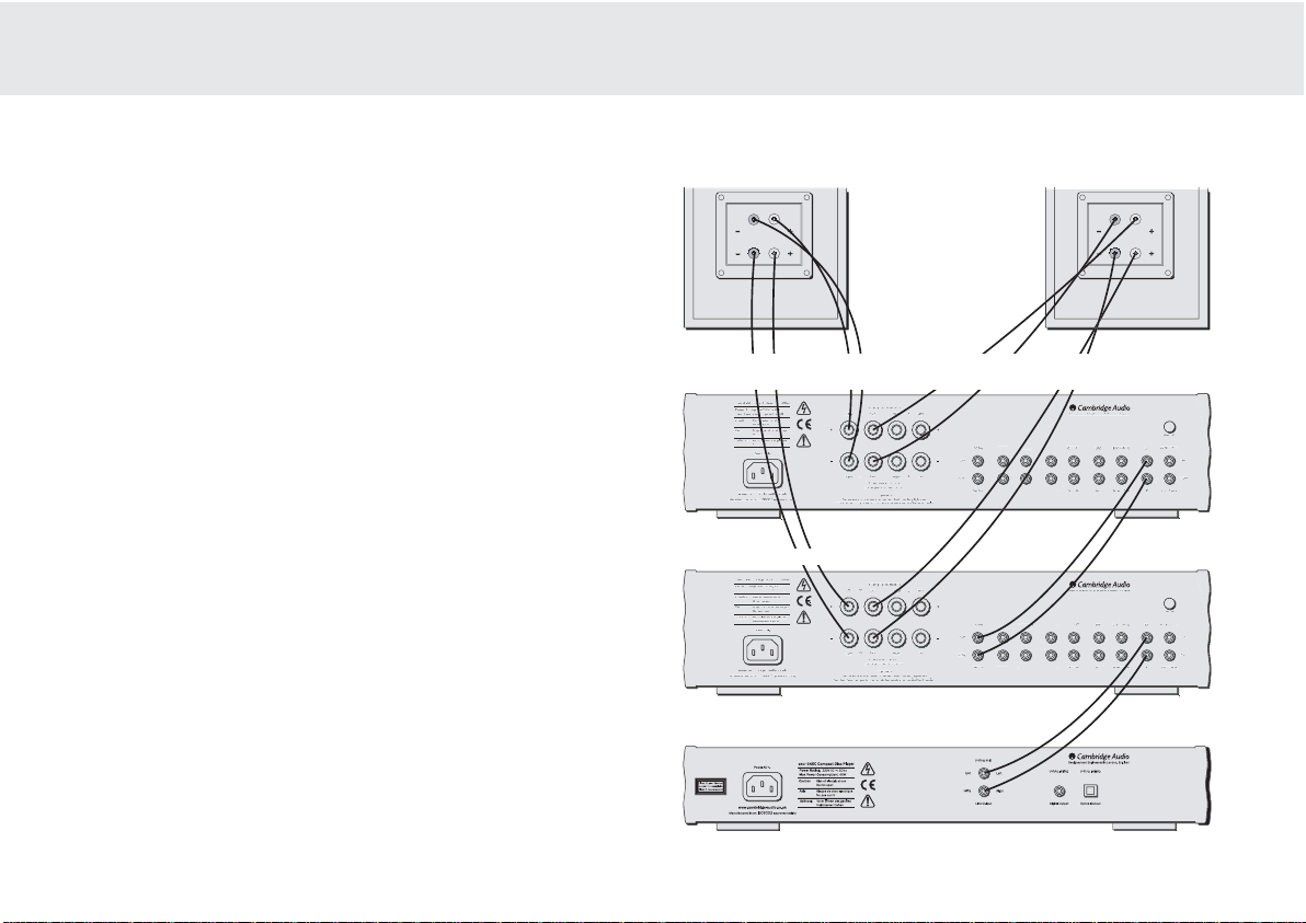
The azur amplifiers are equipped with PRE-OUT sockets. If your
loudspeakers have two sets of terminals then it is possible to bi-amp
your system using a further power amplifier. Bi-amping uses two
amplifiers to drive the bass and treble units in the loudspeakers
independently, resulting in even greater clarity coupled with improved
control and dynamics. An example of a bi-amp setup is illustrated in the
diagram adjacent.
Please note that if using a second azur amplifier as the slave amplifier,
any line input can be used to connect from the master’s Pre-Out.
Using SSpeaker BB connections
The Speaker B connections on the back of the amplifier allow a second
set of speakers to be used, which could be for another room.
Please ensure that loudspeaker terminals are fully tightened
Veuillez s’assurer que les bornes de l’enceinte sont entierement serrees
Veuillez s‘assurer que les bornes de l’enceinte sont entierement serrees
www.cambridge-audio.co.uk
Designed and Engineered in London, England
Risque de choc electrique
azur 640A Integrated Amplifier
Please ensure that loudspeaker terminals are fully tightened
Veuillez s’assurer que les bornes de l’enceinte sont entierement serrees
Veuillez s’assurer que les bornes de l’enceinte sont entierement serrees
Impedance 4 — 8 ohms
Righ
www.cambridge-audio.co.uk
Designed and Engineered in London, England
Risque de choc electrique
azur 640A Integrated Amplifier
Master aamplifier
Slave aamplifier
— if using an integrated amplifier, volume must be set to full
CD player
Bass Bass
Treble Treble
azur 640A Integrated Amplifie
Power Rating:
ax Power Consumptio
615
isk of electric shock
autio
o not open
Risque de choc electriqu
Ne pas ouvrir
Achtun
etzstecker ziehen
ower A
ww.cambridge-audio.co.uk
anufactured in an
SO900
approved facility
azur 640A Integrated Amplifie
Power Rating:
ax Power Consumptio
615
isk of electric shock
o not open
Risque de choc electriqu
as ouvrir
Achtun
etzstecker ziehen
ower A
ww.cambridge-audio.co.uk
anufactured in an
SO900
approved facilit
edance 4 — 8 ohm
Left
A
A
eftRight
edance 4 — 8 ohms
oudspeaker Terminals
Important
Left
eftRight
mpedance 4 — 8 ohms
oudspeaker Terminals
Important
mpedance 4 — 8 ohm
eft
re-Out
eft
ight
Left
eft
Left
eft
ight
re-Out
re-Out
re-Out
Tape In
Tape InRec Out 1Rec Out
esigned and Engineered in London, England
ec Out
ec Out
ec Out
AV / MD
AV / MD
esigned and Engineered in London, England
AV / MD
ape I
Tape In
Righ
t
lease ensure that loudspeaker terminals are fully tightened
ight
lease ensure that loudspeaker terminals are fully tightened
Groun
uner /
ux / Phon
Left
Tuner / DA
Tuner / DA
Righ
Aux / Phon
Groun
Tuner / DAB
Aux / Phon
Left
Righ
Aux / Phon
10
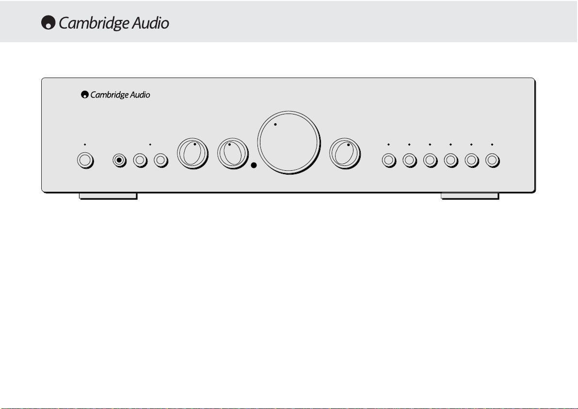
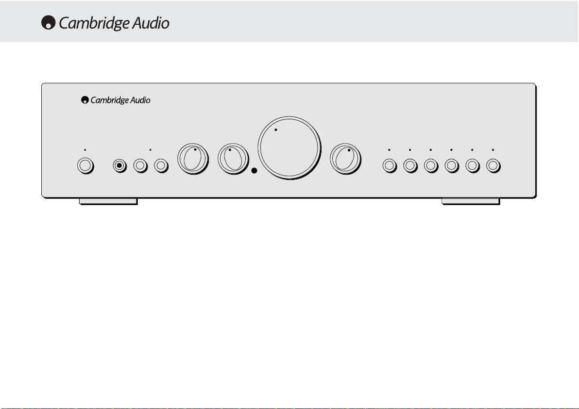
Standby/On
Switches the unit between Standby mode (indicated by dim power LED)
and On (indicated by bright power LED). Standby is a low power mode
where the power consumption is less than 10 Watts. The unit should be
left in standby when not in use.
Headphone ssocket
Allows for the connection of headphones with a ¼» Jack plug connector.
When the headphones are connected the loudspeaker relay is released
switching off the output to the loudspeakers (Speakers A and B).
Speaker BB oon/off
Enables/disables the secondary set of speaker terminals on the back
panel. This can be used for listening to an extra set of speakers in
another room.
Please note that care should be taken when selecting if two
loudspeakers are going to be used on each channel. If the combined
resistance measured on the speaker terminals is too low the amplifier
may not switch out of standby mode until a suitable load resistance is
detected. For more information please see section on CAP5 protection
system.
Note — WWhen uusing ttwo ppairs oof sspeakers eeach ppair sshould bbe rrated aat
least 66 oohms ((or hhigher). 44 oohm
sspeakers aare nnot rrecommended wwhen
using mmore tthan oone ppair.
Direct
This control gives the audio signal a more direct path to the power
amplifier stage of your amplifier, bypassing the tone control circuits for
the purest possible sound quality.
Volume
azur 640A
Integrated Amplifier
TrebleBass
Standby / On
Protection
Direct
Speaker BPhones
Balance
Aux / Phono
CD
DVD
Tape Mon
AV / MDTuner / DAB

540A/640A Integrated amplifier
11
Bass aand ttreble ttone ccontrols
These controls allow subtle adjustments to the tonal balance of the
sound. In the central position these controls have no effect. These
controls only modify the sound through your loudspeakers and the PreOut sockets (where featured), they do not affect the signals sent thr ough
the Tape Out connections. With a well produced CD and a good system
the tone controls are unnecessary and can be switched out. If the
musical recording is of poor quality and/or the
loudspeakers/surroundings are lacking it may be necessary to adjust
the tone controls to compensate.
Volume
The Volume control increases/decreases the lev el of the sound fr om the
outputs of the amplifier. This control affects the le vel of the Loudspeak er
output, the pre amp output and the headphone output. It does not affect
the Tape Out Connections.
It is advisable to turn the Volume control fully anti-clockwise before
switching the amplifier on.
Balance
This control allows you to adjust the relative output levels of the left and
right channels. In the central position the output from each channel is
equal. This control only modifies the sound through your loudspeakers
and the Pre-Out sockets (where featured), it does not affect the signals
sent through the Tape Out connections.
Input sselection ppush bbuttons
Push the appropriate input selection button to select the source
component that you wish to listen to. The signal selected is also fed to
the Tape Out sockets so that it may be recorded. The input should not
be changed whilst recording, although the recorded signal can be
checked using the tape input Tape monitor.
Tape mmonitor sselection bbutton
This control lets you listen to the output signal from a tape recorder or
signal processor connected to the amplifier’s Tape monitor sockets.
When Tape monitor is selected, the source component chosen by the
input selection push buttons continues to be routed to the Tape Out
sockets for recording or processing.
Remote ccontrol ooperation/features
This Amplifier is supplied with a system remote control that operates
both this amplifier and the Cambridge Azur CD players. The functions
relevant to the amplifier are as follows:
Power —
Switches the amplifier between Standby mode and On mode.
Mute —
Mutes the audio (indicated by the input LEDflashing).
Volume ++/-
— The volume buttons increase and decrease the Volume of
the amplifier output.
Input sselect —
The five input select buttons and the Tape monitor select
button are used to change the input source.

12
If the Loudspeaker impedance is low the temperature of the amplifier
may rise faster as the amplifier is working harder. If the amplifier is
mounted in a cabinet or the ventilation slots are obstructed the over
temperature detection may activate/reactivate after a short listening
time.
Short ccircuit ddetection
During power up from standby or during input channel selection CAP5
performs a check on the Loudspeaker terminals to see if a short across
the terminals has been accidentally introduced. If the resistance
measured across the Loudspeaker terminals is too low the unit will stay
in Standby mode until the fault has been removed and Power up is reattempted.
DC ddetection
CAP5 offers Loudspeaker protection if the output of the amplifier goes
to DC because of some internal fault. This is a rare fault although it
could just save those expensive Loudspeakers.
If the amplifier is switched out of standby when the input signal to the
amplifier is too high (with the current volume setting) the CAP5 system
will detect this and reduce the volume to a suitable level.
Overvoltage/overcurrent ddetection
CAP5 offers V/I protection by constantly monitoring the output
transistors to keep them working inside their Safe Operating Area (SOA).
The SOA is a set of limits given by the output transistor manufacturer to
ensure reliability. Many amplifier designers include V/I limiting in the
Cambridge Audio has developed a proprietry protection system to
ensure reliability and a long life to its amplifiers. This protection system
comprises of five main protection methods:
Intelligent cclipping ddetection
CAP5 has the ability to detect when the amplifier starts to clip or
overdrive its output, which can damage Loudspeakers, the amplifier
power supply and most importantly degrade the sound. When CAP5
detects clipping the volume will be automatically nudged down until
CAP5 detects an undistorted* output (*the volume is nudged down until
the distortion is less than 2% which listening tests have shown is
difficult to hear).
It is possible to disable only this feature by holding down the Standby
button during power up (whilst plugging the unit into the mains power).
The unit will indicate this by flashing the protection LED for several
seconds. Disabling the clipping detection is not advised as this feature
has been added to protect the amplifier.
Over ttemperature ddetection
CAP5 includes temperature detection which constantly monitors the
heat generated by the output transistors. When the monitored
temperature reaches a high level (suitably within the limits of the output
devices) the amplifier will automatically switch into a fault mode
(indicated by double flashing of the protection LED). The unit should
ideally be left for 15 minutes in this state to cool down adequately. If the
unit has not fully cooled down then the temperature may reach the limit
soon after the amplifier is powered up.
CAP5 — FIVE WAY PROTECTION SYSTEM
540A/640A Integrated amplifier
13
signal path which can degrade the signal by compressing dynamics. The
CAP5 system operates outside the signal path and when triggered shuts
down the amp rather than limits the size of the signal passing through
the amp (signal compression). V/I protects the amplifier against short
circuits on the speaker terminals during use.
CAP5 has detected that the resistance on the Loudspeaker terminals is
too low. Check to see if there is a short circuit between the Loudspeaker
terminals.
Note: If the indication remains the same and multiple Loudspeakers are
being used on each Loudspeaker output then please remove a pair and
retry. If too many Loudspeakers are connected to any amplifier causing
the Load resistance to drop too low the amplifier will overheat. CAP5 will
detect this situation.
If the indication remains the same with only one set of loudspeakers
connected then there could possibly be a fault with one or both of the
loudspeakers.
CAP5 has detected a user related fault, the internal temperature of the
output transistors has reached the over temperature limit. The unit is not
damaged although it should be left for 15 minutes to cool down before
being switched out of standby.
CAP5 has detected a user related fault, there maybe a short circuit
between the loudspeaker terminals. Please check all Loudspeaker
connections before attempting to switch unit out of standby
CAP5 has detected a fault which requires the unit to be serviced. DC has
been detected on the output of the amplifier which could damage the
speakers. The amplifier is now unusable. Please switch off and contact
dealer.
Protection LED flashes for 4 seconds when unit attempts to come out of
Standby mode.
Unit has switched off during operation. Protection LED constantly
ddoouubbllee
ffllaasshheess..
Unit has switched off during operation. Protection LED constantly
ffllaasshheess
oonn aanndd ooffff iinn bbuurrssttss ooff 44
.
Unit has switched off during operation. Protection LED is
oonn wwiitthh aa bbrriieeff
ooffff ffllaasshh
.
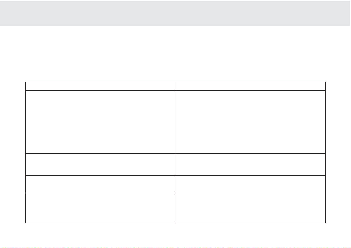
Indication
Fault/Remedy

14
There iis nno ppower
Ensure the AC power cord is connected securely.
Ensure the plug is fully inserted into the wall socket and is switched on.
Check fuse in the mains plug or adaptor
There iis nno ssound
Make sure the unit is not in Standby mode
Check that source component is properly connected
Check that ‘TAPE MON’ is not switched on (unless tape input is req uired)
Check that your speakers are properly connected
If using Speaker B terminals check they are switched on
If channel LED is flashing turn mute off
There iis nno ssound oon oone cchannel
Ensure that balance control is in the correct position
Check speaker connections
Check interconnects
There iis aa lloud bbuzz oor hhum
Check turntable or tone arm for ground and connection lead fault
Ensure no interconnects are loose or defective
Ensure that your tape deck/turntable is not too close to the amplifier
Unable tto mmake oor pplay ttape rrecordings
Check that TAPE MON and TAPE OUT have been connected correctly
There iis wweak bbass oor ddiffused sstereo iimaging
Ensure that speakers are not wired out of phase
Will nnot sswitch oout oof sstandby — pprotection LLED flashing
Please see section on CAP5 protection system
Protection LLED flashing
Please see section on CAP5 protection system (page 12)
TROUBLESHOOTING
Power OOutput
Max PPower
Consumption
Standby PPower
Consumption
THD (unweighted)
Freq RResponse
(-33dB)
S tto NN RRatio
(unweighted)
Slew RRate
(into 88ΩΩ)
Dimensions
(HxWxD)
mm
inches
Weight
kg
Lbs
SPECIFICATIONS
540A 640A
100W (into 4Ω)
65W (into 8Ω)
615W
6W
1kHz < 0.005%
20kHz < 0.07%
4Hz — 80kHz
92dB
50V/uS
100 x 430 x 310
3.9 x 16.9 x 12.2
7
15.4
75W (into 4Ω)
50W (into 8Ω)
515W
6W
1kHz < 0.009%
20kHz < 0.09%
5Hz — 50kHz
92dB
30V/uS
100 x 430 x 310
3.9 x 16.9 x 12.2
7
15.4

540A/640A Integrated amplifier
15
Cambridge Audio warrants this product to be free from defects in
materials and workmanship (subject to the terms set forth below).
Cambridge Audio will repair or replace (at Cambridge Audio’s option) this
product or any defective parts in this product. W arranty periods may v ary
from country to country. If in doubt consult your dealer and ensure that
you retain proof of purchase.
To obtain warranty service, please contact the Cambridge Audio
authorised dealer from which you purchased this product. If your dealer
is not equipped to perform the repair of your Cambridge Audio product,
it can be returned by your dealer to Cambridge Audio or an authorised
Cambridge Audio service agent. You will need to ship this product in
either its original packaging or packaging affording an equal degree of
protection.
Proof of purchase in the form of a bill of sale or receipted invoice, which
is evidence that this product is within the warranty period, must be
presented to obtain warranty service.
This Warranty is invalid if (a) the factory-applied serial number has been
altered or removed from this product or (b) this product was not
purchased from a Cambridge Audio authorised dealer. You may call
Cambridge Audio or your local country Cambridge Audio distributor to
confirm that you have an unaltered serial number and/or you pur chased
from a Cambridge Audio authorised dealer.
This Warranty does not cover cosmetic damage or damage due to acts
of God, accident, misuse, abuse, negligence, commercial use, or
modification of, or to any part of, the product. This Warranty does not
cover damage due to improper operation, maintenance or installation,
or attempted repair by anyone other than Cambridge Audio or a
Cambridge Audio dealer, or authorised service agent which is authorised
to do Cambridge Audio warranty work. Any unauthorised repairs will void
this Warranty. This Warranty does not cover products sold AS IS or WITH
ALL FAULTS.
REPAIRS OR REPLACEMENTS AS PROVIDED UNDER THIS WARRANTY
ARE THE EXCLUSIVE REMEDY OF THE CONSUMER. CAMBRIDGE AUDIO
SHALL NOT BE LIABLE FOR ANY INCIDENTAL OR CONSEQUENTIAL
DAMAGES FOR BREACH OF ANY EXPRESS OR IMPLIED WARRANTY IN
THIS PRODUCT. EXCEPT TO THE EXTENT PROHIBITED BY LAW, THIS
WARRANTY IS EXCLUSIVE AND IN LIEU OF ALL OTHER EXPRESS AND
IMPLIED WARRANTIES WHATSOEVER INCLUDING, BUT NOT LIMITED TO,
THE WARRANTY OF MERCHANTABILITY AND FITNESS FOR A PRACTICAL
PURPOSE.
Some countries and US states do not allow the exclusion or limitation of
incidental or consequential damages or implied warranties so the above
exclusions may not apply to you. This Warranty gives you specific legal
rights, and you may have other statutory rights, which vary from state to
state or country to country.
LIMITED WARRANTY

16
Vielen DDank, ddass SSie ssich ffür ddie AAnschaffung eeines CCambridge AAudio-
Verstärkers aaus dder AAzur-SSerie e
entschieden hhaben. DDieses GGerät iist ddas
Resultat uunserer bbis hheute aaufwendigsten FForschung uund EEntwicklung.
Wir wwünschen IIhnen mmit ddiesem EErgebnis llangjährige FFreude.
Einige DDetails
Planung und Entwicklung jedes puristischen Hifi-Verstärker-Konzepts
konzentriert sich im Wesentlichen auf zwei Baugruppen, die
Stromversorgung und eine möglichst effiziente Treiberstufe
(Vorverstärker) zur Ansteuerung der Leistungstransistoren, also der
eigentlichen Endstufe. Dem Cambridge Audio Entwickler-Team ist es
gelungen, in diesen beiden wichtigen Bereichen die bestmögliche
Lösung zu finden, um technisch Machbares in einem bisher nicht
dagewesenen Preis-/Leistungsverhältnis zu realisieren. Die bewährten
Leistungstransistoren der Verstärker Azur 540A / 640A kamen schon in
den äußerst erfolgreichen Vorgänger-Modellen zum Einsatz. Die
vorgeschalteten Verstärker-Stufen wurden jedoch komplett neu
entwickelt.
Auf Grund des überaus durchdachten Layouts, sorgfältig plazierter
Bauteile und kurzer Signalwege ergibt sich eine extrem hohe Stabilität
der Verstärkerschaltung. Kompensationsschaltungen können somit auf
ein Minimum reduziert werden. Verzerrungen können drastisch
reduziert werden. Dynamik und auch die Bandbreite von 80 kHz (!) wünschenswert für die hochauflösenden Formate wie DVD-Audio und
SACD — werden den Anforderungen neuer Medien gerecht.
Der Klang und die Performance eines Hifi-Verstärkers werden sehr oft
durch eine begrenzte Dynamik der Stromversorgung limitiert. Kräftige
Ringkern-Transformatoren, parallel geschaltete Speicherkondensatoren
sowie Bypass-Kondensatoren garantieren jederzeit eine saubere,
dynamische Stromversorgung. Dies wiederum ermöglicht ein
kraftvolles, dynamisches Klangbild voller natürlicher Details und Fülle.
Besondere Aufmerksamkeit wurde der Auswahl passiver Bauteile
gewidmet, welche insbesondere nach klanglichen Kriterien ausgewählt
wurden. Im Azur 640A kommen zudem spezielle PolypropylenKondensatoren zum Einsatz, insbesondere an klanglich sensiblen
Punkten im Signalweg.
Hifi-Puristen können das Klangregelnetzwerk des Azur 540A / 640A bei
Bedarf komplett überbrücken. Es wird somit vollständig aus dem
Signalweg entfernt. Der Anschluß eines Kopfhörers ist ebenfalls
möglich. Er wird direkt aus der kraftvollen Endstufe gespeist.
Eine neu entwickelte innovative Schutzschaltung, das Cambridge Audio
CAP5 System , schützt die Verstärker Azur 540A / 640A vor einer
Vielzahl möglicherweise auftretenden Defekte oder Fehlbedienungen.
Dies geschieht durch prozessorgesteuerte Überwachung, ohne
zusätzliche aktive Bauteile im Signalweg.
All unser Wissen und langjährige Erfahrung haben wir in die neue Azur
Generation einfließen lassen. Mit viel Liebe zum Detail entstanden HifiVerstärker, die klanglich wegen ihrer hohen Auflösung und Dynamik
überzeugen. Sie begeistern durch eine lebhafte, fließende Darbietung
jeder Art von Musik. Diese Verstärker beziehen den Hörer ins
Klanggeschehen voll ein!
Um das musikalische Potential dieses Gerätes voll ausschöpfen zu
können, empfehlen wir sehr, bei der Auswahl der übrigen Komponenten
Ihrer Stereoanlage auf ebenso hohe Qualität zu achten. Natürlich raten
EINLEITUNG

540A/640A HIFI-Verstärker
17
wir zu den weiteren Komponenten unserer Cambridge Audio Azur-Line.
Denn diese sind auf demselben hohen Niveau wie Ihr neuer Verstärker
entwickelt worden.
Darüber hinaus sollten Sie auf eine hochwertige Verkabelung Ihrer
Geräte und Lautsprecher achten. Die Verwendung minderwertiger
Verbindungs- und Lautsprecherkabel limitiert die klanglichen
Fähigkeiten Ihres Wiedergabesystems, welches immer nur so gut sein
kann, wie sein schwächstes Glied in der Kette. Aus diesem Grund legen
wir unseren Geräten keine «Billig-Beipack-Kabel» bei. Ihr Händler bietet
Ihnen Cambridge Audio Kabel, die garantieren, dass Ihre Hifi-Anlage ihr
ganzes Potential entfaltet.
Nun lladen wwir SSie eein, ssich zzurückzulehnen uund MMusik eentspannt zzu
genießen!
Matthew Bramble
Technical Director
Einleitung………………………………………………………………………………………16
Sicherheitshinweise……………………………………………………………………….18
Installation…………………………………………………………………………………… 19
Anschlüsse auf der Geräterückseite……………………………………………….20
Hilfe zum Anschluß Ihrer Komponenten…………………………………………..22
Bedienungshinweise………………………………………………………………………24
CAP5 — Schutzschaltung………………………………………………………………….26
Problembehandlung………………………………………………………………………28
Technische Daten…………………………………………………………………………. 28
Haftungsbeschränkung………………………………………………………………… 29
INHALT
18
Überprüfung dder NNetzspannung
Zu Ihrer eigenen Sicherheit bitten wir Sie, die folgenden Hinweise
sorgfältig zu lesen, bevor Sie dieses Gerät mit dem Stromnetz
verbinden.
Stellen Sie sicher, dass die Netzspannungsangabe auf der
Geräterückseite mit der Höhe der Netzspannung vor Ort übereinstimmt.
Nur bei Übereinstimmung ist ein fehlerfreier, sicherer Betrieb
gewährleistet. Der Anschluss an abweichende Netzspannungen als am
Gerät angegeben kann zu erheblichen Beschädigungen führen.
Wird das Gerät über einen längeren Zeitraum nicht benutzt, so sollte es
vom Stromnetz getrennt werden. Verwenden Sie zum Anschluss nur das
beiliegende Netzkabel oder andere hochwertige Kabel mit
Erdungskontakt! Der Kontakt mit der Netzspannung ist
lebensgefährlich! Öffnen Sie niemals das Gehäuse, sondern überlassen
Sie dieses qualifiziertem Servicepersonal.
Dieses Zeichen warnt vor nicht isolierten Bereichen. Bei
unqualifizierter Lightning flash Handhabung besteht die
Gefahr eines elektrischen Schlags.
Wichtige Hinweise sind im Folgenden mit diesem Zeichen
gekennzeichnet:
Dieses Gerät entspricht den europäischen
Standards für Sicherheit (73/23/EEC) und
elektromagnetischer Verträglichkeit (89/336/EEC),
sofern alle Hinweise in dieser Anleitung beachtet
werden. Aus diesem Grunde dürfen bei eventuellen
Reparaturen nur Originalersatzteile von Cambridge Audio
verwendet werden. Bei Nichtbeachtung und/oder Modifikationen
jeglicher Art erlischt jeder Gewährleistungsanspruch!
SICHERHEITSHINWEISE

540A/640A HIFI-Verstärker
19
Bitte nehmen Sie sich einen Moment Zeit, um die folgenden Hinweise zu
lesen, bevor Sie Ihren Azur Verstärker anschließen. Dies wird Ihnen
ermöglichen, sichere Betriebsbedingungen zu schaffen, sowie ein
Optimum an Klang und Leistung zu gewährleisten.
Stellen Sie den Verstärker auf eine feste, ebene Standfläche. Das Gerät
benötigt eine ausreichende Belüftung. Stellen Sie es deshalb nicht auf
einen Teppich oder eine andere weiche Unterlage, und verdecken Sie
nicht die Lüftungsschlitze. Stellen Sie das Gerät nicht in ein
geschlossenes Fach oder in einen geschlossenen Schrank.
Schützen Sie das Gerät vor jeglichem Kontakt mit Wasser oder anderen
Flüssigkeiten. Stellen Sie sicher, daß keine kleineren Gegenstände in
die Belüftungsschlitze fallen können. Sollte solch ein Fall trotzdem
einmal eintreten, schalten Sie bitte das Gerät sofort aus! Ziehen Sie den
Stecker, und fragen Sie gegebenenfalls ihren Händler um Rat.
Verlegen Sie das Netzkabel sorgfältig! Vermeiden Sie, daß andere
Gegenstände oder Geräte darauf stehen oder es beschädigen können.
Da das Netzteil des Verstärkers ein leichtes Magnetfeld erzeugt, sollte
ein eventuell angeschlossener Plattenspieler nicht in unmittelbarer
Nähe stehen.
Wie alle audiophilen Hifi-Produkte benötigt auch Ihr Azur Verstärker eine
gewisse Einspielzeit. Abhängig von der täglichen Betriebsdauer beträgt
diese ca. 1-2 Wochen. Kondensatoren und einige aktive Bauteile
benötigen diese Zeit der «Formatierung», um ihr volles Klangpotential zu
erreichen.
Die Verstärker Azur 540A / 640A können in Betriebspausen, in denen
keine Musik gehört wird, in den Standby Modus geschaltet werden.
Sollte der Verstärker jedoch für längere Zeit nicht benutzt werden,
empfehlen wir die komplette Trennung vom Stromnetz durch
Herausziehen des Netzsteckers aus der Steckdose.
Zur Reinigung des Azur Verstärkers verwenden Sie bitte ein leicht
feuchtes, Fussel freies Tuch. Benutzen Sie niemals aggressive
Reinigungsmittel welche z.B. Alkohol, Ammoniak oder Scheuermittel
enthalten. Benutzen Sie auch keine Sprays am V erstärk er , oder in seiner
Nähe.
Es befinden sich keinerlei Einstellungsmöglichkeiten im Inneren des
Gerätes, welche durch den Benutzer verändert werden können, um die
Wiedergabe in irgendeiner Weise zu beeinflussen! Ein eventuell
notwendiger Eingriff in das Gerät sollte ausschließlich autorisiertem
Fachpersonal vorbehalten sein. Versuchen Sie niemals das Gerät zu
öffnen. Der Kontakt mit der Netzspannung ist lebensgefährlich! Bei
Auftauchen eines Problems oder Fehlers wenden Sie sich bitte zuerst an
Ihren Händler.
INSTALLATION
20
230-2240Volt AAnschluß
Bevor Sie den Verstärker mittels des beiliegenden Netzkabels mit dem
Stromnetz verbinden, stellen Sie bitte zunächst alle Verbindungen zu
weiteren Hifi Geräten und den Lautsprechern her. Nach Einstecken des
Netzkabels sollten Sie einen kurzen «Systemcheck» vornehmen. Dabei
werden alle Anzeigen auf der Gerätefront kurz aufleuchten.
Abschließend geht der Verstärker in den Standby Modus und ist nun
betriebsbereit.
Lautsprecher AAnschlüsse
Auf der Rückseite der Azur 540A / 640A Verstärker befinden sich die
Lautsprecher-Anschlüsse A und B. Gruppe A ist die HauptlautsprecherGruppe und nicht schaltbar. Gruppe B ist mit einem entsprechenden
Schalter an der Gerätefront zu- oder abschaltbar. Verbinden Sie nun die
Lautsprecherkabel entsprechend der Zuordnung zu Ihren
Lautsprechern mit den Terminals Right (Rechts) + & — und Left (Links) +
& — der Lautsprechergruppe A und/oder B. Achten Sie bitte besonders
auf gute und feste Verbindungen, und stellen Sie sicher das kein
Kurzschluß zwischen + & — bzw. von den Anschlüssen zur
Geräterückwand entstehen kann. Gute Lautsprecherkabel und
Kontakte verbessern den Klang und die Leistungsfähigkeit Ihres
Verstärkers!
Achtung: DDie AAzur 5540A // 6640A VVerstärker ssind ffür LLautsprecher-
Impedanzen vvon 44-88 OOhm aausgelegt. E
Entsprechende HHinweise bbefinden
sich iin dder RRegel aauf ddem AAnschlußfeld IIhrer LLautsprecher. IIm
Zweifelsfall zziehen SSie bbitte IIhren HHändler zzu RRate.
Achtung: AAlle iim FFolgenden bbeschriebenen AAnschlüsse ssind a
analoge EEin-
bzw. AAusgänge uund ddürfen nnie mmit ddigitalen AAus- bbzw. EEingängen
verschiedener GGeräte vverbunden wwerden!
Please ensure that loudspeaker terminals are fully tightened
Veuillez s’assurer que les bornes de l’enceinte sont entierement serreesVeuillez s‘assurer que les bornes de l’enceinte sont entierement serrees
www.cambridge-audio.co.uk
Designed and Engineered in London, England
Risque de choc electrique
Vorm offnen des geratesVorm offnen des gerates
azur 640A Integrated Amplifier
ANSCHLÜSSE AUF DER GERÄTERÜCKSEITE
zur 640A Integrated Amplifie
Power Rating:
ax Power Consumption
isk of electric shoc
aution
o not ope
Avis
Risque de choc electrique
Ne pas ouvrir
Achtung
etzstecker ziehen
ower A
ww.cambridge-audio.co.u
anufactured in an
SO900
615W
approved facility
ight
ight
A
oudspeaker Terminals
lease ensure that loudspeaker terminals are fully tightened
eft
eft
mpedance 4 — 8 ohms
Important
mpedance 4 — 8 ohms
ight
ight
Left
eft
esigned and Engineered in London, England
Groun
re-Out
ape In
ec Out 1
eft
ape InRec Out 1Rec Out
re-Out
AV / MD
Rec Out
AV / MD
uner / DAB
Tuner / DAB
D
CDCDAux / Phon
ux / Phono
eft
ight

540A/640A HIFI-Verstärker
21
Pre OOut
Lautstärke geregelter Vorverstärker-Ausgang, zum Anschluß externer
Endstufen oder aktiver Subwoofer und aktiver Lautsprecher (Seite 9).
Tape IIn
Eingang zum Anschluß eines Kassettenrecorders oder ähnlicher
Aufzeichnungsgeräte mit analogem Hochpegelausgang (Seite 8).
Rec OOut 11 // 22
Ausgänge zum Anschluß beliebiger analoger Aufzeichnungsgeräte
(Kassettenrecorder, Tonbandgerät) oder digitaler Geräte (MiniDisc, CD
Recorder) mit analogem Eingang. Beide Ausgänge liefern das gleiche
Signal (Seite 8).
CD, TTuner/DAB, DDVD, AAV/MD
Verschiedene Hochpegel Eingänge, welche mit den entsprechend
genannten Geräten oder anderen Hochpegel Quellen verbunden werden
können.
Aux/Phono
Im Auslieferungszustand ist dieses ein weiterer Eingang für eine
beliebige Hochpegel-Quelle wie z.B. einen CD- Player, einen Tuner oder
ein ähnliches Gerät. Alternativ kann hier ein analoger Plattenspieler mit
M/M (Moving Magnet) System angeschlossen werden, sofern das
entsprechende Cambridge Audio Phonomodul PM01 installiert wurde.
Der Einbau kann bei Bedarf von Ihrem Händler vorgenommen werden.
Ground
Ein eventuell vorhandenes separates Massekabel eines Plattenspielers
kann hier mit dem Chassis des Verstärkers verbunden werden.
22
Die Azur Verstärker 540A / 640A bieten vielfältigen
Anschlussmöglichkeiten, Ihr Audio-System zu installieren. Mit den
folgenden Grafiken möchten wir Ihnen beim Anschluss Ihrer Geräte
behilflich sein.
Standard VVerbindungen
Die Grafik zeigt den Anschluß eines CD-Players und des linken und
rechten Lautsprechers an die Lautsprecher Gruppe A.
Anschluß eeines AAufzeichnungsgerätes
Diese Grafik zeigt den möglichen Anschluß eines Kassettenrecorders
oder eines Aufzeichnungsgerätes mit analogen Ein- und Ausgängen.
HILFE ZUM ANSCHLUß IHRER KOMPONENTEN
Please ensure that loudspeaker terminals are fully tightened
Veuillez s’assurer que les bornes de l’enceinte sont entierement serrees
Veuillez s’assurer que les bornes de l’enceinte sont entierement serrees
www.cambridge-audio.co.uk
Designed and Engineered in London, England
Risque de choc electrique
azur 640A Integrated Amplifier
Please ensure that loudspeaker terminals are fully tightened
Veuillez s’assurer que les bornes de l’enceinte sont entierement serrees
Veuillez s’assurer que les bornes de l’enceinte sont entierement serrees
www.cambridge-audio.co.uk
Designed and Engineered in London, England
Risque de choc electrique
azur 640A Integrated Amplifier
zur 640A Integrated Amplifier
Power Rating:
ax Power Consumption
isk of electric shock
o not ope
Risque de choc electriqu
as ouvrir
tun
etzstecker ziehe
ower AC
ww.cambridge-audio.co.uk
anufactured in an
ISO900
615W
approved facilit
Impedance 4 — 8 ohms
eft
Right
A
t
ight
Left
ight
Impedance 4 — 8 ohms
Loudspeaker Terminals
Important
lease ensure that loudspeaker terminals are fully tightened
eft
re-Out
eft
ight
ec Out
Pre-Ou
esigned and Engineered in London, Englan
ec Out 1
ape I
ec Out
ec Out
ape I
AV / MD
roun
Tuner / DAB
Aux / Phono
Tuner / DAB
ight
CD
ux / Phon
zur 640A Integrated Amplifier
Power Rating:
ax Power Consumption
615W
isk of electric shock
o not ope
Risque de choc electriqu
as ouvrir
tun
etzstecker ziehe
ower AC
ww.cambridge-audio.co.uk
anufactured in an
ISO900
approved facilit
Impedance 4 — 8 ohms
eft
Right
t
ight
Left
ight
Impedance 4 — 8 ohms
Loudspeaker Terminals
Important
lease ensure that loudspeaker terminals are fully tightened
eft
re-Out
eft
ight
ape In
Pre-Ou
ape In 1
ec Out 1
ec Out 1Rec Out
esigned and Engineered in London, Englan
Rec Out
AV / MD
roun
Tuner / DAB
Aux / Phono
Tuner / DAB
ight
CD
ux / Phon
540A/640A HIFI-Verstärker
23
«Bi-aamping»
Ein mögliches Anschlußschema für sogenanntes «Bi-amping», die
getrennte Ansteuerung von Bass- und Mittel/Hochton-Bereich, zeigt die
Grafik auf dieser Seite. Diese Variante sorgt in der Regel für eine
bessere Dynamik und Auflösung. Voraussetzung ist ein entsprechender
Anschluß an Ihren Lautsprechern zur Auftrennung der Frequenzweiche.
Es müssen zwei Verstärker eingesetzt werden. Ihr Fachhändler wird Sie
bei Bedarf Print graphic for Bi-amping diesbezüglich beraten.
Lautsprecher GGruppe ‚‚B’
Möchten Sie gelegentlich ein zusätzliches Lautsprecherpaar
hinzuschalten, zum Beispiel in einem anderen Raum, so können Sie
dieses an die Gruppe B anschließen. Es kann jedoch nur das gleiche
Programm gehört werden, welches über die Hautlautsprecher der
Gruppe A wiedergegeben wird.
Getrennte Ansteuerung mit unterschiedlichem Programm ist nicht
möglich.
Please ensure that loudspeaker terminals are fully tightened
Veuillez s’assurer que les bornes de l’enceinte sont entierement serrees
Veuillez s‘assurer que les bornes de l’enceinte sont entierement serrees
www.cambridge-audio.co.uk
Designed and Engineered in London, England
Risque de choc electrique
azur 640A Integrated Amplifier
Please ensure that loudspeaker terminals are fully tightened
Veuillez s’assurer que les bornes de l’enceinte sont entierement serrees
Veuillez s’assurer que les bornes de l’enceinte sont entierement serrees
Impedance 4 — 8 ohms
Righ
www.cambridge-audio.co.uk
Designed and Engineered in London, England
Risque de choc electrique
azur 640A Integrated Amplifier
Hauptverstärker
Slave-VVerstärker
— bei Verwendung eines integrierten Verstärkers muss die
Lautstärke auf die höchste Stufe eingestellt werden
CD-SSpieler
Bass Bass
Treble Treble
azur 640A Integrated Amplifie
Power Rating:
ax Power Consumptio
isk of electric shock
autio
o not open
Risque de choc electriqu
Ne pas ouvrir
Achtun
etzstecker ziehen
ower A
ww.cambridge-audio.co.uk
anufactured in an
SO900
615
approved facility
edance 4 — 8 ohm
Left
A
Righ
t
eftRight
A
edance 4 — 8 ohms
oudspeaker Terminals
Important
lease ensure that loudspeaker terminals are fully tightened
eft
Left
azur 640A Integrated Amplifie
Power Rating:
ax Power Consumptio
isk of electric shock
o not open
Risque de choc electriqu
as ouvrir
Achtun
etzstecker ziehen
ower A
ww.cambridge-audio.co.uk
anufactured in an
SO900
615
approved facilit
mpedance 4 — 8 ohm
Left
ight
eftRight
mpedance 4 — 8 ohms
oudspeaker Terminals
Important
lease ensure that loudspeaker terminals are fully tightened
eft
Left
eft
ight
eft
ight
re-Out
re-Out
re-Out
re-Out
ape I
Tape In
Tape In
ec Out
Tape InRec Out 1Rec Out
ec Out
ec Out
esigned and Engineered in London, England
AV / MD
AV / MD
esigned and Engineered in London, England
AV / MD
Groun
uner /
ux / Phon
Left
Tuner / DA
Tuner / DA
Righ
Aux / Phon
Groun
Tuner / DAB
Aux / Phon
Left
Righ
Aux / Phon
24
Standby/On
Mit dieser Taste schalten Sie das Gerät von der Bereitschaftsfunktion
(Standby) in die Betriebsfunktion (On) und umgekehrt. Im Standby
Modus leuchtet die blaue Betriebsanzeige mit verminderter Helligkeit.
Kopfhörer BBuchse ((Phones)
An diese Buchse kann jeder passive Stereo- oder Mono-Kopfhörer mit
6.3mm Klinkenstecker angeschlossen werden. Die angeschlossenen
Lautsprecher (Gruppe A und B !) werden dadurch automatisch
abgeschaltet.
Lautsprecher GGruppe ‚‚B’
Über die Taste Speaker B können die an Lautsprecher Gruppe B
angeschlossenen Lautsprecher ein- bzw. ausgeschaltet werden, zum
Beispiel zur gelegentlichen Beschallung eines anderen Raumes.
Hierbei ist zu beachten, dass die Gesamtimpedanz der Lautsprecher pro
Kanal nicht unter 4 Ohm sinken darf! Andernfalls kann es passieren,
dass die CAP5 Schutzschaltung das Gerät abschaltet, bzw. das
Einschalten aus dem Standby Modus nicht möglich ist. Bei Anschluß von
zwei Lautsprechern pro Kanal, also Gruppe A und B, sollte daher die
Impedanz jedes einzelnen Lautsprechers mindestens 8 Ohm betragen.
‚Direct’ TTaste
Mit der Taste Direct ist es möglich, die Klangregelung zu überbrücken,
und somit vollständig aus dem Signalweg zu entfernen. Bei Wiedergabe
sorgfältig produzierter Aufnahmen und einer guten Abstimmung Ihres
Hifi-Systems ist eine Klangregelung selten notwendig.
Volume
azur 640A
Integrated Amplifier
TrebleBass
Standby / On
Protection
Direct
Speaker BPhones
Balance
Aux / Phono
CD
DVD
Tape Mon
AV / MDTuner / DAB

540A/640A HIFI-Verstärker
25
Klangregelung
Die Azur 540A / 640A Verstärker besitzen getrennte Regler für Bässe
(Bass) und Höhen (Trebble), um das Klangbild bei Bedarf anzupassen.
In Mittelstellung befinden sich diese in «neutraler» Position, ohne
Einwirkung auf den Klang. Die Klangregelung hat keinerlei Einfluß auf
die Rec Out 1/2 Ausgänge, sondern wirkt nur auf die Pre Out Buchsen
und die Lautsprecher, bzw. auf den Kopfhörer-Ausgang.
Lautstärke EEinstellung
Der Volume Regler verändert sowohl die Lautstärke für die
angeschlossenen Lautsprecher, den Kopfhörer, als auch den
Ausgangspegel an den Pre Out Buchsen. Er hat keinen Einfluß auf die
Rec Out 1/2 Ausgänge.
Bitte drehen Sie den Regler immer gegen den Uhrzeigersinn auf «Null»,
bevor Sie den Verstärk er aus dem Standby Modus einschalt en oder eine
der Eingangswahl Taste betätigen.
Balance EEinstellung
Mit dem Balance Einsteller haben Sie die Möglichkeit, das LautstärkeVerhältnis zwischen dem linken und rechten Kanal zu verändern, um so
eine Anpassung an schwierige örtliche Bedingungen vorzunehmen. Der
Regler hat keinerlei Einfluß auf die Rec Out 1/2 Ausgänge.
Eingangswahlschalter
Mit den Eingangswahltasten wählen Sie die entsprechende Tonquelle,
die Sie hören möchten. Das laufende Musikprogramm kann gleichzeitig
über die Rec Out 1/2 Buchsen an ein Aufnahmegerät weitergeleitet
werden. Dem entsprechend darf während einer Aufnahme nicht auf
eine andere Tonquelle umgeschaltet werden!
Tape MMonitor
Über die Tape Monitor-Taste kann bei einem Aufnahmegerät mit
Hinterbandkontrolle eine laufende Aufnahme abgehört und kontrolliert
werden. Durch Ein- und Ausschalten der Tape Monitor Funktion können
Sie Original und Aufnahme vergleichen.
Gegebenenfalls können Sie über diese Taste auch einen
Signalprozessor «einschleifen».
Infrarot FFernbedienung
Die zum Lieferumfang gehörende Fernbedienung steuert die
wichtigsten Funktionen der Azur 540A/ 640A Verstärker.
Power —
Mit dieser Taste schalten Sie das Gerät von der
Bereitschaftsfunktion (Standby) in die Betriebsfunktion (On) und
umgekehrt. Im Standby-Modus leuchtet die blaue Betriebsanzeige mit
verminderter Helligkeit.
Mute —
Stummschaltung. Die Eingangswahl Anzeige blinkt, bis die
Funktion durch erneutes Drücken der Mute Taste aufgehoben wird.
Volume ++/-
— Fernsteuerung des Lautstärke-Reglers.
Des Weiteren kann über die entsprechend gekennzeichnet en Tasten die
Eingangswahl und die Tape Monitor Funktion gesteuert werden.

26
Überwachung dder LLautsprecherausgänge
Bei jedem Einschalten des Verstärkers aus dem Standby Modus
kontrolliert CAP5 die Lautsprecherausgänge bezüglich möglicher
entstandener Kurzschlüsse. Wird ein Kurzschluß oder ein zu
niederohmiger Lautsprecher erkannt, verbleibt der Verstärker im
Standby Modus. Erst nach Beseitigung des Fehlers ist das Einschalten
des Gerätes möglich.
Erkennung vvon GGleichspannung
CAP5 erkennt eine für Lautsprecher gefährliche Gleichspannung an den
Lautsprecherausgängen. Wird dies durch einen Fehler in der Endstufe
verursacht, schaltet CAP5 den Verstärker ab.
Gleichspannungsanteile können jedoch auch durch ein übersteuertes
oder verzerrtes Eingangssignal entstehen. Wird dies nach Einschalten
aus dem Standby Modus erkannt, wird zunächst die Lautstärke
heruntergeregelt.
Schutz ggegen ÜÜberspannung uund ÜÜberlastung
Durch umfassende Überwachung der Leistungsendstufe gewährleistet
CAP5 sichere und konstante Arbeitsbedingungen für die
Leistungstransistoren. Oft liegen Kontroll- und Regelschaltungen im
Signalweg und begrenzen das Nutzsignal im Falle eines auftretenden
Fehlers oder Problems. Nicht so beim CAP5 System !
Das Monitorsystem befindet sich nicht im Signalweg. Bei einem
kritischen Betriebszustand wird der Verstärker deshalb abgeschaltet.
Cambridge Audio hat für die Azur 540A / 640A Verstärker spezielle
Schutzschaltungen entwickelt, das CAP5-System. Es handelt sich im
Wesentlichen um 5 Funktionen zur Absicherung gegen mögliche
Defekte, Überlastungen oder Fehlbedienung:
Intelligentes SSystem zzur EErkennung vvon VVerzerrungen
CAP5 erkennt Verzerrungen durch Überlastung oder Übersteuerung der
Endstufe, sogenannte Clipping-Effekte, die den Klang erheblich
beeinträchtigen und zu Beschädigungen der Lautsprecher und Teilen
des Verstärkers führen können. CAP5 reduziert in so einem Fall
automatisch die Lautstärke so weit, bis ein unverzerrtes Signal erkannt
wird, bzw. die Verzerrungen unter 2% abfallen. Dieser Wert hat sich bei
ausgiebigen Hörtests als unkritisch erwiesen.
Schutz ggegen ÜÜberhitzung
CAP5 erkennt eine mögliche Überhitzung der Endstufen durch
konstante Überwachung der Kühlkörper-Temperatur. Erreicht die
Temperatur einen für die Endstufentransistoren kritischen Wert,
schaltet der Verstärker in einen Fehler-Modus, erkennbar durch
doppeltes Blinken der Protection LED. Unter normalen Bedingungen
können Sie den Verstärker nach ca. 15 Minuten wieder in Betrieb
nehmen.
Wird der Verstärker über einen längeren Zeitraum stark belastet, oder
mit niederohmigen Lautsprechern betrieben, ist unbedingt auf
genügend Freiraum zur Wärmeableitung zu achten, andernfalls wird die
Schutzschaltung sehr früh und entsprechend häufig ansprechen!
CAP5 — SCHUTZSCHALTUNG

540A/640A HIFI-Verstärker
27
CAP5 hat eine zu geringe Impedanz am Lautsprecherausgang erkannt.
Überprüfen Sie die Lautsprecherterminals und Kabelverbindungen auf
mögliche Kurzschlüsse und beseitigen Sie diese ggfls.
Ist kein Kurzschluß vorhanden, liegt es möglicherweise daran, dass zu
niederohmige Lautsprecher angeschlossen sind, bzw. die
Gesamtimpedanz aus Gruppe A und Gruppe B zu niedrig ist. Entfernen
Sie deshalb ein Boxenpaar.
Sollte auch dann das Einschalten nicht möglich sein, ist eventuell das
verbliebene Boxenpaar zu niederohmig oder es liegt ein Def ekt an einem
oder beiden Lautsprechern vor.
CAP5 hat einen von Außen, bzw. durch den Benutzer v erursachten Fehler
oder eine Überlastung erkannt. Die Betriebstemperatur der Endstufe hat
einen kritischen Wert erreicht. In der Regel liegt kein Defekt im Gerät vor,
es sollte jedoch für entsprechende Abkühlung gesorgt werden. Unter
normalen Betriebsbedingungen kann der Verstärker nach ca. 15
Minuten wieder eingeschaltet werden.
CAP5 hat einen von außen, bzw. durch den Benutzer verursachten F ehler
erkannt. Möglicherweise liegt ein Kurzschluß an den
Lautsprecherausgängen vor. Überprüfen Sie alle Anschlüsse, Kabel und
Lautsprecher und beseitigen Sie die Ursache.
CAP5 hat einen internen Fehler am Gerät erkannt. Es wurde eine hohe
Gleichspannung am Lautsprecherausgang festgestellt, welche die
Lautsprecher gefährden könnte. Das Gerät ist nicht weiter benutzbar.
Trennen Sie das Gerät von Stromnetz und wenden Sie sich an Ihren
Händler oder die zuständige Servicestelle um den Fehler zu heben.
Die Protection LED blinkt für 4 Sekunden während der Verstärker
versucht aus dem Standby Modus einzuschalten.
Das Gerät hat während des Betriebes abgeschaltet. Die Protection LED
bblliinnkktt ffoorrttwwäähhrreenndd iinn ddooppppeelltteenn IInntteerrvvaalllleenn
.
Das Gerät hat während des Betriebes abgeschaltet. Die Protection LED
bblliinnkktt ffoorrttwwäähhrreenndd iinn 44 ffaacchheenn IInntteerrvvaalll
leenn
.
Das Gerät hat während des Betriebes abgeschaltet. Die Protection LED
iisstt aann uunndd ffllaacckkeerrtt mmiitt hhoohheerr FFrreeqquueennzz
.
Anzeige
Fehler // AAbhilfe

28
Das GGerät iist oohne SStrom
Kontrollieren Sie den korrekten und festen Sitz des Netzkabels in der
Steckdose und am Gerät.
Überprüfen Sie die Funktion der Steckdose, eventuell durch Anschluß einer
Lampe oder eines anderen Gerätes.
Kein TTon üüber ddie LLautsprecher
Möglicherweise befindet sich der Verstärker noch im Standby Modus.
Schalten Sie ihn ein.
Überprüfen Sie alle Verbindungen zu den anderen Geräten und die
Lautsprecheranschlüsse.
Eventuell ist die Tape Monit or- Funktion eingeschaltet. Schalten Sie diese ab,
es sei denn, Sie möchten das Programm eines angeschlossenen Recorders
wiedergeben.
Blinkt die LED der Eingangswahl? Schalten Sie die Mute-Funktion mit der
Fernbedienung ab.
Kein TTon aauf eeinem KKanal
Überprüfen Sie alle Verbindungen zu den anderen Geräten und die
Lautsprecheranschlüsse.
Stellen Sie den Balance Regler in die Mittelposition.
Laute SStörgeräusche ooder BBrummen iin dden LLautsprechern
Überprüfen Sie verschiedene Tonquellen bezüglich der Störungen. Tritt das
Problem nur bei einer Quelle auf (z.B. CD-Player), oder sind die Störungen nur
auf einem Kanal zu hören, dann ist eventuell ein Verbindungskabel defekt.
Sind die Störungen auf beiden Kanälen zu hören, handelt es sich meistens
um Einstreuungen, verursacht durch externe Geräte oder kritische
Kabelführung.
Es kkönnen kkeine AAufnahmen ggemacht wwerden
Überprüfen Sie die Verbindungen zu den Tape In & Rec Out 1/2 Buchsen.
Diffuses KKlangbild // EEingeschränkte SStereo PPerspektive
Möglicherweise ist bei einer oder beiden Lautsprecherverbindungen die
Polung vertauscht. Kontrollieren Sie den korrekten Anschluß von + & — .
Der VVerstärker lläßt ssich nnicht aaus ddem SStandby MModus
einschalten
Beachten Sie die Hinweise zum CAP5 System auf den Seiten 12 u. 13.
PROBLEMBEHANDLUNG
Ausgangsleistung
Max.
Leistungsaufnahme
Standby
Leistungsaufnahme
THD
(ungewichtet)
Frequenzverhalten
(-33dB)
Rauschabstand
(ungewichtet)
Anstiegsgeschwindigkeit
(Slew RRate) ((an 88W ΩΩ)
Abmessungen
(HxBxT)
mm
Zoll
Gewicht
kg
Lbs
TECHNISCHE DATEN
540A 640A
100W (an 4Ω)
65W (an 8Ω)
615W
6W
1kHz < 0,005%
20kHz < 0,07%
4Hz — 80kHz
92dB
50V/uS
100 x 430 x 310
3,9 x 16,9 x 12,2
7
15,4
75W (an 4Ω)
50W (an 8Ω)
515W
6W
1kHz < 0,009%
20kHz < 0,09%
5Hz — 50kHz
92dB
30V/uS
100 x 430 x 310
3,9 x 16,9 x 12,2
7
15,4

540A/640A HIFI-Verstärker
29
Cambridge Audio garantiert Ihnen, dass dieses Produkt keine Materialund Herstellungsfehler (wie im Folgenden näher erläutert) aufweist.
Cambridge Audio repariert oder ersetzt (nach der freien Entscheidung
von Cambridge Audio) dieses Produkt oder ein eventuelles defektes Teil
in diesem Produkt. Die Garantiedauer kann in den einzelnen Ländern
unterschiedlich sein. Wenn Sie Fragen zu der Garantie haben, wenden
Sie sich bitte an Ihren Händler. Bewahren Sie den Kaufnachweis immer
auf.
Wenn Sie Garantieleistungen in Anspruch nehmen möchten, wenden
Sie sich bitte an den von Cambridge Audio autorisierten Händler, bei
dem Sie das Produkt gekauft haben. Sollte dieser Händler nicht in der
Lage sein, Ihr Cambridge Audio-Produkt zu reparieren, kann dieser das
Produkt an Cambridge Audio oder eine autorisierte Cambridge AudioKundendienststelle zurücksenden. Das Produkt muss entweder in der
Originalverpackung oder einer Verpackung, die einen gleichwertigen
Schutz bietet, versandt werden.
Sie müssen einen Kaufnachweis in Form einer Kaufurkunde oder einer
quittierten Rechnung vorlegen, wenn Sie einen Anspruch auf
Garantieleistungen geltend machen. Aus diesem Kaufnachweis muss
abzulesen sein, dass sich das Produkt im Garantiezeitraum befindet.
Diese Garantie wird ungültig, wenn (a) die bei der Herstellung
angebrachte Seriennummer bei diesem Produkt geändert oder entfernt
wurde oder (b) dieses Produkt nicht bei einem von Cambridge Audio
autorisierten Händler gekauft wurde. Wenden Sie sich an Cambridge
Audio oder den lokalen Cambridge Audio-Vertrieb in Ihrem eigenen
Land, um sicher zu stellen, dass Ihre Seriennummer nicht geändert
wurde und/oder dass Sie bei einem von Cambridge Audio autorisierten
Händler gekauft haben.
Die Garantie gilt nicht für kosmetische Schäden oder Schäden durch
höhere Gewalt, Unfälle, unsachgemäße Behandlung, Unachtsamkeit,
kommerziellen Einsatz oder durch Änderungen des Produkts bzw. von
Teilen des Produkts. Diese Garantie umfasst keine Schäden durch
unsachgemäßen Betrieb, unsachgemäße Wartung oder Installation
oder durch Reparaturen, die von anderen Personen als von Cambridge
Audio oder einem Cambridge Audio-Händler oder einem autorisierten
Kundendienstmitarbeiter, der von Cambridge Audio für das Ausführen
von Garantieleistungen befugt ist, vorgenommen werden. Durch jede
nicht autorisierte Reparatur wird diese Garantie unwirksam. Diese
Garantie gilt nicht für Produkte, die verkauft werden AS IS (WIE SIE
SIND) oder WITH ALL FAULTS (MIT ALLEN FEHLERN).
DIE HAFTUNGSANSPRÜCHE DES BENUTZERS BESCHRÄNKEN SICH AUF
DIE IN DIESER GARANTIE ENTHALTENEN REPARATUREN ODER
ERSATZLEISTUNGEN. CAMBRIDGE AUDIO HAFTET NICHT FÜR
ZUFÄLLIGE ODER FOLGESCHÄDEN DURCH DIE VERLETZUNG
IRGENDEINER AUSDRÜCKLICHEN ODER IMPLIZITEN GARANTIE BEI
DIESEM PRODUKT. A UßER DORT, WO DIES GESETZLICH UNTERSAGT IST,
IST DIESE GARANTIE EXKLUSIV UND TRITT SIE AN DIE STELLE ALLER
ANDEREN AUSDRÜCKLICHEN ODER IMPLIZITEN GARANTIEN, WELCHER
ART AUCH IMMER, EINSCHLIEßLICH, ABER NICHT BESCHRÄNKT AUF,
VERKAUFSGARANTIE UND FUNKTIONSGARANTIE FÜR EINEN
PRAKTISCHEN ZWECK.
Einige Länder und US-Staaten erlauben keinen Ausschluss oder keine
Beschränkung von zufälligen oder Folgeschäden bzw. impliziten
Garantien, so dass die oben genannten Ausschlüsse für Sie eventuell
nicht gelten. Diese Garantie erteilt Ihnen spezifische gesetzliche Rechte;
es ist auch möglich, dass Sie andere Rechtsansprüche haben, die in
jedem Staat und jedem Land anders aussehen können.
HAFTUNGSBESCHRÄNKUNG

30
Merci dd‘avoir aacheté ccet aamplificateur CCambridge AAudio dde lla ggamme
Azur. CCet aamplificateur eest lle ppro
duit dde ll‘un dde nnos pprogrammes dde
recherche eet dde ddéveloppement lles pplus aambitieux ddepuis qque nnous
fabriquons ddes pproduits aaudio dde hhaute qqualité, ssoit ddepuis pplus dde 330
ans. NNous eespérons qque vvous aapprécierez sses rrésultats eet qque vvous
pourrez pprofiter llongtemps dde sses qqualités ssonores eexceptionnelles.
A ppropos dde ccet aamplificateur
Le processus de conception d’un ampli audio haute qualité nécessite que l’on
porte une attention particulière à deux éléments principaux : l’alimentation
électrique et la capacité de l’étage d’excitation à fournir un étage de sortie
efficace. A Cambridge Audio, nos travaux de recherche ont toujours eu pour but
d’atteindre le meilleur niveau de performance dans ces domaines, à un prix
abordable. La topologie de l’Azur 540A/640A utilise les mêmes périphériques de
sortie testés et approuvés utilisés par Cambridge Audio dans ses anciens modèles
primés d’amplificateurs, avec de nombreuses heures de recherche et de
développement consacrées aux étages précédents. Les circuits de l’amplificateur
sont essentiellement composés d’une paire d’entrées pour courant en rapport
géométrique chargées par un miroir de courant et excitées par une source de
courant transitoire compensé, pilotant un étage de gain en tension en cascade
(béta élevé). L’étage de sortie compensé thermiquement a été réglé pour donner
des conditions optimales de classe AB (pour une distorsion de croisement
grandement réduite causée par le réchauffement dynamique en cas de panne de
la sortie). De plus, la topologie inclut une amélioration supplémentaire de l’étage
d’excitation : un montage suiveur de classe A conçu pour isoler les transistors de
l’amplificateur de tension de la lourde charge des transistors de sortie. Cette
augmentation de l’excitation de l’étage de sortie, combinée à un nouveau circuit
avant à régime transitoire, permet de doubler la vitesse de balayage à 40V/uS.
Grâce à une topologie intelligente des cartes de circuits imprimés, à un placement
judicieux des composants et à des chemins de signaux très courts, nos
amplificateurs offrent une stabilité exceptionnelle, ce qui permet de diminuer la
taille des composants de compensation. Ceci permet de diminuer les effets de
distorsion, d’augmenter la dynamique et d’obtenir une bande passante très
importante (80kHz), un avantage idéal pour les sources à bande passante élevée
‘meilleures que les CD’, comme les DVD-Audio et les Super Audio CD.
Tout amplificateur v oit ses performances limitées par les aptitudes dynamiques de
son alimentation électrique. Pour cette raison, les amplificateurs de la gamme
Cambridge Azur incorporent un grand nombre de caractéristiques, notamment un
transformateur toroïdal à faible flux, une mise en parallèle des condensateurs
réservoirs et l’utilisation judicieuse des condensateurs de dérivation, afin de
permettre un rendu propre de la charge aux moments les plus opportuns. On
obtient ainsi la reproduction d’un son ouvert et naturel, tout en assurant une
réponse positive en cas de changement soudain du signal reproduit.
Nous avons également porté une attention particulière à la qualité des
composants passifs, qui ont été soigneusement sélectionnés pour leurs
avantages sonores. De plus, l’Azur 640A utilise des condensateurs de dérivation
de signaux en polypropylène haute qualité afin d’améliorer le traitement
dynamique et la circulation des signaux.
Les amplificateurs Cambridge Audio Azur 540A et 640A offrent également des
commandes de tonalité pouvant être déconnectées d’un circuit en mode ‘direct’
pour un trajet du signal le plus court et donc le plus pur. Parmi les autres
caractéristiques de ces amplificateurs, on notera des prises phono plaqué or 24k,
des boucles doubles pour magnétophone, une sortie préampli, une prise pour le
casque et une série secondaire de terminaux haut-parleurs haut niveau.
Une nouvelle caractéristique est offerte en standard sur le 540A et le 640A: le
système novateur de protection CAP5 conçu par Cambridge Audio. Ce système est
composé d’un microprocesseur de contrôle continu de l’amplificateur, fournissant
ainsi une protection générale contre toute une gamme de défauts possibles. Le
système a été obtenu sans l’ajout de circuits actifs supplémentaires dans le trajet
du signal, permettant ainsi de ne pas altérer les qualités sonores ou les aptitudes
dynamiques de l’amplificateur.
Après de longues heures d’écoute et de peaufinage, Cambridge Audio dispose
désormais de connaissances très vastes et très pointues. Cette attention aux
INTRODUCTION
Loading…
- About
- Blog
- Projects
- Help
-
Donate
Donate icon
An illustration of a heart shape - Contact
- Jobs
- Volunteer
- People
Bookreader Item Preview
texts
Cambridge Audio Azur 640A User`s manual
- Addeddate
- 2021-01-07 16:21:09
- Identifier
- manualzz-id-1010746
- Identifier-ark
- ark:/13960/t9096719b
- Ocr
- tesseract 4.1.1
- Ocr_autonomous
- true
- Ocr_detected_lang
- ky
- Ocr_detected_lang_conf
- 1.0000
- Ocr_detected_script
-
Latin
Cyrillic
- Ocr_detected_script_conf
-
0.9277
0.0723
- Ocr_module_version
- 0.0.10
- Ocr_parameters
- -l kir+deu+dan+spa+eng+fra+rus+ita+nld+Cyrillic+Latin
- Page_number_confidence
- 99.12
comment
Reviews
There are no reviews yet. Be the first one to
write a review.
414
Views
DOWNLOAD OPTIONS
Temporarily Unavailable
DAISY
For users with print-disabilities
Uploaded by
chris85
on
SIMILAR ITEMS (based on metadata)

100
Мы благодарим Вас за покупку этого аудио усилителя серии Azur
фирмы Cambridge Audio. Он является результатом нашей наиболее
интенсивной в течение трех десятилетий научно-
исследовательской и производственной программы по созданию
высококачественных звуковых изделий. Мы надеемся, что Вы
оцените ее результаты и будете многие годы получать
удовольствие при прослушивании.
Об этом усилителе
Разработка любого аудио усилителя с чистым звуком, главным образом,
сосредоточена на двух главных областях: блок электропитания и
способность эффективного управления выходной ступенью. Мы, в
фирме Cambridge Audio, разработали наилучшие из возможных способов
достижения самых высоких эксплуатационных качеств в этих областях
при разумной цене. Топологическая схема серии Azur 540A/640A
использует те же самые проверенные и испытанные устройства выпуска
компании Cambridge Audio, которые применялись в предыдущих,
отмеченных наградами моделях усилителей, но все же на исследование
и развитие предшествующих вариантов было затрачено много часов
исследований. Схема этого оконечного усилителя — это, по существу,
согласованная дифференциальная входная пара, нагруженная токовым
зеркалом и управляемая от источника тока с компенсацией в
переходном процессе, и управляющая затем каскодной ступенью
усиления напряжения с высоким коэффициентом передачи.
Температурно-компенсированная выходная ступень настроена так,
чтобы обеспечить оптимальный режим класса AB (для резкого
уменьшения поперечного искажения, вызванного динамическим
нагревом выходных элементов). Помимо совершенствования топологии,
в задающий каскад введено дальнейшее усовершенствование,
состоящее в использовании чистого повторителя класса A для изоляции
транзисторов усилителя напряжения от интенсивной нагрузки выходных
транзисторов. Эта возросшая подача тока к выходной ступени, в
комбинации с новой схемой прямого действия с ускорением переходного
процесса, удваивает скорость нарастания выходного напряжения до
40В/uS.
Благодаря существенно усовершенствованной печатной плате,
тщательному расположению компонентов и сокращению длины
проводников, стабильность этих усилителей исключительно высока, что
позволило уменьшить размеры компенсирующих компонентов. Это
привело к уменьшению искажений, улучшению динамики и расширению
полосы пропускания вплоть до 80кГц, что представляет собой
идеальное решение для новых, ‘лучших, чем компакт-диски’
широкополосных носителей типа аудио DVD-диски и супер-аудио
компакт-диски.
Эффективность любого усилителя ограничена динамическими
возможностями его блока питания, и по этой причине усилители серии
Cambridge Azur содержат многие усовершенствования, включая
тороидальный трансформатор с пониженным потоком, параллельное
размещение корпусов конденсаторов и осмотрительное использование
блокировочных конденсаторов, что при необходимости обеспечивает
мгновенную подачу энергии. Это гарантирует воспроизведение богатого
и естественного звука и обеспечивает быструю реакцию на любые
динамичные или резкие переходы в воспроизводимом сигнале.
Особое внимание было также уделено качеству пассивных компонентов,
которые были тщательно выбраны с учетом их преимуществ для
звуковоспроизведения. Вдобавок к этому, для улучшения передачи
сигнала и динамики в серии Azur 640A используются
высококачественные сигнальные шунтирующие конденсаторы на
основе полипропилена.
Усилители 540A и 640A серии Azur компании Cambridge Audio также
имеют тональные регуляторы, которые могут быть исключены из цепи в
‘прямом’ режиме для создания самого короткого и поэтому самого
чистого пути для сигнала. К другим особенностям относятся звуковые
разъемы с покрытием из 24-каратного золота, сдвоенные ленточные
проводники, выход предварительного усилителя, разъем для наушников
и вторичный набор разъемов для динамиков высшего уровня.
Важная особенность, которая была включена как стандарт в оба
усилителя 540A и 640A, — это новаторская защитная система CAP5,
разработанная компанией Cambridge Audio. Она состоит из
микропроцессора, который постоянно следит за усилителем,
ВВЕДЕНИЕ
Раздел: Бытовая, кухонная техника, электроника и оборудование
Тип: Ресивер/Усилитель
Инструкция к Ресиверу/Усилителю Cambridge Audio Azur 640A

azur 540A/640A
Integrated amplifier / HIFI-Verstärker / Amplificateur intégré / Amplificador integrado / Amplificatore
integrato / Geïntegreerde versterker / Integreret forstærker / Встроенный усилитель
User’s manual / Bedienungsanleitung / Mode d’emploi / Manual del usuario / Manuale per l’utente /
Gebruikershandleiding / Brugermanual / Руководство для пользователя

INTRODUCTION
Thank yyou ffor ppurchasing tthis CCambridge AAudio aazur sseries aamplifier. IIt
reduced in size. This has the effect of reducing distortion, increasing
is tthe rresult oof oour mmost eext
ensive eever rresearch aand ddevelopment
dynamics and allowing the bandwidth to be opened up to a massive
program iin oover tthree ddecades oof pproducing hhigh qquality aaudio pproducts.
80kHz, ideal for the new ‘better than CD’ high bandwidth sources such
We hhope tthat yyou wwill aappreciate tthe rresults aand eenjoy mmany yyears oof
as DVD-Audio and Super Audio CD.
listening ppleasure.
The performance of any amplifier is limited by the dynamic abilities of its
power supply, and for this reason Cambridge Azur amplifiers incorporate
many features, including a low flux toroidal transformer, paralleling of
About tthis aamplifier
the reservoir capacitors and careful use of bypass capacitors, to allow
The design of any purist audio amplifier is mainly centred on two main
the instantaneous clean delivery of charge whenever it is needed. This
areas, the Power Supply and the driver stage’s ability to drive the output
ensures an open and natural sound being reproduced and ensures a
stage effectively. We at Cambridge Audio have researched the best
positive response to any dynamics or sudden transients in the signal
possible ways to achieve the highest performance in these areas, at a
being reproduced.
sensible price. The Azur 540A/640A topology uses the same tried and
Particular attention has also been paid to the quality of the passive
tested output devices that Cambridge Audio have used in previous
components which have been carefully chosen for their sonic benefits.
award winning amplifier models, but many hours of research have gone
The Azur 640A in addition uses high grade Polypropylene signal bypass
into the study and development of the preceding stages. This driver
capacitors to improve signal flow and dynamics.
circuitry is essentially a matched differential input pair, loaded by a
current mirror and driven from a transient compensated current source
The Cambridge Audio Azur 540A and 640A amplifiers also incorporate
driving a high beta cascoded voltage gain stage. The thermally
tone controls, which may be switched out of circuit in ‘direct’ mode for
compensated output stage is setup to inherently give optimum Class AB
the shortest and therefore purest signal path. Other features include
conditions (for greatly reduced cross over distortion caused by dynamic
24k gold plated phono sockets, dual tape loops, pre amp output, a
heating of the output dies). In addition the topology includes a further
headphone socket and a secondary set of high level loudspeaker
improvement to the driver stage consisting of a pure class-A follower to
terminals.
isolate the voltage amplifier transistors from the difficult loading of the
An important feature which has been included as standard on both the
output transistors. This increased current drive to the output stage
540A and 640A is the new innovative Cambridge Audio designed CAP5
combined with a novel transient feed forward circuit doubles the slew
protection system. This consists of a microprocessor which constantly
rate to 40V/uS.
monitors the amplifier providing comprehensive protection against a
Due to critically refined circuit board layouts, careful component
variety of possible faults. This has been achieved without adding any
placement and short signal paths the stability of these amplifiers is
active circuitry into the signal path to degrade the sound or the dynamic
extremely high which allows the compensation components to be
abilities of the amplifier.
2

540A/640A Integrated amplifier
CONTENTS
Cambridge Audio has built up an extensive knowledge base due to
Introduction…………………………………………………………………………………….2
meticulous listening and tweaking. This attention to detail results in
amplifiers that are totally convincing in the reproduction of both tonal
Safety precautions…………………………………………………………………………..4
colour and dynamic contrast, deliver a vibrant and fluid performance
with music of all types and are extremely musically involving.
Installation………………………………………………………………………………………5
To get the absolute best from this equipment we would encourage you
to use only high quality source components. Of course we particularly
Rear panel connections …………………………………………………………………..6
recommend tuners and digital equipment from the Cambridge Audio
range, all of which have been designed to the same exacting standards
Connecting…………………………………………………………………………………….. 8
as our amplifiers. Many types of loudspeakers were used in the
development of these amplifiers to ensure maximum compatibility with
Operating instructions……………………………………………………………………10
a wide variety of designs.
Interconnects and speaker cables are also something that shouldn’t be
CAP5 — Five way protection system…………………………………………………..12
overlooked. Please do not compromise your system’s performance by
using poor quality cables to connect source components to your
Troubleshooting……………………………………………………………………………..14
amplifier or the amplifiers output to your loudspeakers. A system is only
as good as its weakest link. For this reason we do not include cheap
Specifications………………………………………………………………………………..14
«freebie» cables with any of our products. Your dealer can supply good
quality Cambridge Audio interconnects and Mordaunt Short/Gale
Limited warranty…………………………………………………………………………… 15
loudspeaker cables that will make a noticeable improvement to the
sound quality of your system.
Now wwe iinvite yyou tto ssit bback, rrelax aand eenjoy!
Matthew Bramble
Technical Director
3
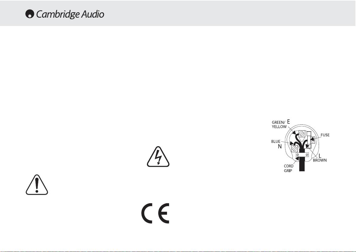
SAFETY PRECAUTIONS
Checking tthe ppower ssupply rrating
Plug ffitting iinstructions ((UK only)
For your own safety please read the following instructions carefully before
The cord supplied with this appliance is factory fitted with a 13A mains plug fitted
attempting to connect this unit to the mains.
with a 3A fuse inside. If it is necessary to change the fuse, it is important that a 3A
one is used. If the plug needs to be changed because it is not suitable for your
Check that the rear of your unit indicates the correct supply voltage. If your mains
socket, or becomes damaged, it should be cut off and an appropriate plug fitted
supply voltage is different, consult your dealer.
following the wiring instructions below. The plug must then be disposed of safely,
as insertion into a 13A socket is likely to cause an electrical hazard. Should it be
This unit is designed to operate only on the supply voltage and type that is
necessary to fit a 3-pin BS mains plug to the power cord the wires should be fitted
indicated on the rear panel of the unit. Connecting to other power sources may
as shown in this diagram. The colours of the wires in the mains lead of this
damage the unit.
appliance may not correspond with the coloured markings identifying the
This equipment must be switched to Standby mode when not in use, unplugged if
terminals in your plug. Connect them as follows:-
not used for long periods of time, and must not be used unless correctly earthed.
The wire which is coloured BLUE must be
To reduce the risk of electric shock, do not remove the unit’s cover (or back). There
connected to the terminal which is marked
are no user serviceable parts inside. Refer servicing to qualified service personnel.
with the letter ‘N’ or coloured BLACK.
If the power cord is fitted with a moulded mains plug the unit must not be used if
the plastic fuse carrier is not in place. Should you lose the fuse carrier the correct
The wire which is coloured BROWN must be
part must be reordered from your Cambridge Audio dealer.
connected to the terminal which is marked
with the letter ‘L’ or coloured RED
The lightning flash with the arrowhead symbol within an equilateral
triangle is intended to alert the user to the presence of uninsulated
The wire which is coloured GREEN/YELLOW
‘dangerous voltage’ within the product’s enclosure that may be of
must be connected to the terminal which is
sufficient magnitude to constitute a risk of electric shock to
marked with the letter ‘E’ or coloured
persons.
GREEN.
The exclamation point within an equilateral triangle is intended to
If your model does not have an earth wire,
alert the user to the presence of important operating and
then disregard this instruction.
maintenance instructions in the service literature relevant to this
appliance.
If a 13 Amp (BS 1363) plug is used, a 3 Amp fuse must be fitted, or if any other
type of plug is used a 3 Amp or 5 Amp fuse must be fitted, either in the plug or
This product complies with European Low Voltage (73/23/EEC)
adaptor, or on the distribution board.
and Electromagnetic Compatibility (89/336/EEC) Directives
when used and installed according to this instruction manual. For
continued compliance only Cambridge Audio accessories should
be used with this product and servicing must be referred to
qualified service personnel.
4

540A/640A Integrated amplifier
INSTALLATION
Please take a moment to read these notes before installing your
To clean the unit, wipe its case with a moist, lint-free cloth. Do not use
amplifier, they will enable you to get the best performance and prolong
any cleaning fluids containing alcohol, ammonia or abrasives. Do not
the life of the product.
spray an aerosol at or near the amplifier.
The unit requires ventilation above and below. Do not situate it on a rug
These units are not user serviceable, never attempt to repair,
or other soft surface and do not obstruct the air inlet and outlet grilles
disassemble or reconstruct the unit if there seems to be a problem. A
on the underside and top cover. Do not place in an enclosed area such
serious electric shock could result if this precautionary measure is
as a bookcase or in a cabinet.
ignored. In the event of a problem or failure, please contact your dealer.
This unit must not be exposed to dripping or splashing water or other
This unit should be installed on a sturdy, level surface. Due to stray
liquids. No objects filled with liquid, such as vases, shall be placed on
magnetic fields turntables should not be located nearby due to
the unit. In the event, switch off immediately, disconnect from the mains
interference.
supply and contact your dealer for advice.
Ensure that small objects do not fall through any ventilation grille. If this
happens, switch off immediately, disconnect from the mains supply and
contact your dealer for advice.
Do not route the power cable so that it can be walked upon or damaged
by other items near it.
Electronic audio components have a running in period of around a week
(if used several hours per day). This will allow the new components to
settle down, the sonic properties will improve over this time.
It is recommended that when bi-amping, the same type power amplifiers
are used.
This amplifier has been designed to be left in Standby mode when not
in use, this will increase the life of the amplifier (this is true with all
electronic equipment). If you do not intend to use this unit for a long
period of time, unplug it from the mains socket.
5
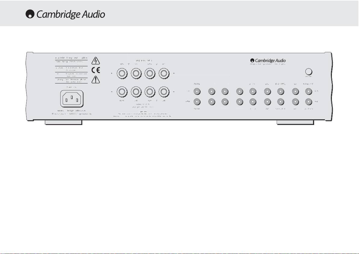
AC power ssocket
Note: TThis aamplifier hhas bbeen ddesigned ffor uuse wwith lloudspeakers tthat
have aa nnominal iimpedance oof bbe
tween 44 aand 88 oohms.
Once you have completed all connections to the amplifier, plug the AC
Power Cable into an appropriate mains socket. The amplifier is now
Please eensure tthat tthe sspeaker tterminals hhave bbeen ttightened
ready for use.
adequately tto pprovide a
a ggood eelectrical cconnection. IIt iis ppossible ffor tthe
sound qquality tto bbe aaffected iif tthe sscrew tterminals aare lloose.
Loudspeaker cconnections
Pre aamp oouts
The 540A and 640A have two sets of Loudspeaker terminals on the rear
panel, speakers A and B. Speakers A are the main speaker terminals,
Connect these sockets to the inputs on an external Power Amplifier(s).
speakers B are the secondary switchable speaker terminals. Connect
the wires from your left channel loudspeaker to the LEFT + & — terminals,
Tape mmon
and likewise the wires from the right channel loudspeaker to the RIGHT
+ & — terminals. In each case the red terminal is the positive output, and
These sockets can be connected to a tape deck or to the analog sockets
the black terminal is the negative input. Care should be taken to ensure
on a MiniDisc or CD recorder. Connect an interconnect cable from the
no stray strands of wire are shorting speaker outputs together. Please
recorder’s Line Out sockets to the amplifier’s Tape Monitor sockets. This
6
T
ape In
R
ec Out 1
R
ec Out
2
T
ape In
R
ec Out 1
Rec Out
2
M
ax Power Consum
p
tion
:
615W
P
re-Out
Pre-Out
I
mpedance
4
— 8 ohms
Impedance 4 — 8 ohms
L
oudspeaker Terminals
Loudspeaker Terminals
Important
Important
P
lease ensure that loudspeaker terminals are fully tightened
Please ensure that loudspeaker terminals are fully tightened
Veuillez s’assurer que les bornes de l’enceinte sont entierement serreesVeuillez s‘assurer que les bornes de l’enceinte sont entierement serrees
I
mpedance 4 — 8 ohms
Impedance 4 — 8 ohms
R
ight
Right
L
eft
Left
R
ight
Right
L
eft
Left
Left
Left
B
B
A
A
R
ight
Right
L
eft
Left
R
ight
Right
B
B
A
A
AV / MD
AV / MD
DVD
DVD
T
uner / DAB
Tuner / DAB
CD
CD
Aux / Phon
o
Aux / Phono
P
re-Out
Pre-Out
AV / MD
AV / MD
D
VD
DVD
Tuner / DAB
Tuner / DAB
C
D
CD
A
ux / Phono
Aux / Phono
R
ight
Right
L
eft
Left
Ri
g
h
t
Right
L
eft
Left
Groun
d
Ground
w
ww.cambridge-audio.co.u
k
www.cambridge-audio.co.uk
M
anufactured in an
Manufactured in an
I
SO900
2
ISO9002
approved facility
approved facility
P
ower A
C
Power AC
D
esigned and Engineered in London, England
Designed and Engineered in London, England
R
isk of electric shoc
k
Risk of electric shock
D
o not ope
n
Do not open
C
aution
Caution
Ris
q
ue de choc electri
q
ue
Risque de choc electrique
Ne
p
as ouvrir
Ne pas ouvrir
Avis
Avis
Vorm offnen des geratesVorm offnen des gerates
N
etzstecker ziehen
Netzstecker ziehen
Achtung
Achtung
a
zur 6
4
0A Integrated Amplifie
r
azur 640A Integrated Amplifier
Power Rating:
Power Rating:
230V AC 50Hz
230V AC 50Hz
REAR PANEL CONNECTIONS

540A/640A Integrated amplifier
monitor doubles up as the standard tape/recording medium input.
Ground cconnection
Note: WWhen cconnecting aa ssource ccomponent tthat hhas bboth aan iinput aand
If you are connecting a turntable to your amplifier then its ground wire
output ii.e. aa ttape rrecorder, tthe o
output oof wwhich sshould aalways bbe
should be attached to this point
connected tto tthe TTape MMon iinput. TThis wwill eeliminate hhowlround iif tthe
wrong iinput cchannel iis sselected.
Tape oout
These sockets can be connected to a tape deck or to the analog sockets
on a MiniDisc or CD recorder. Connect an interconnect cable from the
Tape Out sockets of this amplifier to the recorder’s Line In. Please note
that this unit has two tape loops which have identical outputs.
CD/Tuner/DVD/AV/MD iinput ssockets
These inputs are suitable for any ‘line level’ source equipment such as
CD players, DAB or FM/AM tuners etc.
Aux/Phono iinput ssockets
Connect any ‘line level’ source equipment to these sockets i.e. CD player
or DAB tuner. Alternatively this particular input can be converted to a
dedicated turntable if desired although to do this a Cambridge Audio
PM01 Phono Module must be fitted. Please contact your Cambridge
Audio dealer who can supply and install a phono stage to your amplifier.
These iinputs aare ffor aanalog aaudio ssignals oonly. TThey sshould nnot bbe
connected tto tthe ddigital ooutput oo
f aa CCD pplayer oor aany oother ddigital ddevice.
7
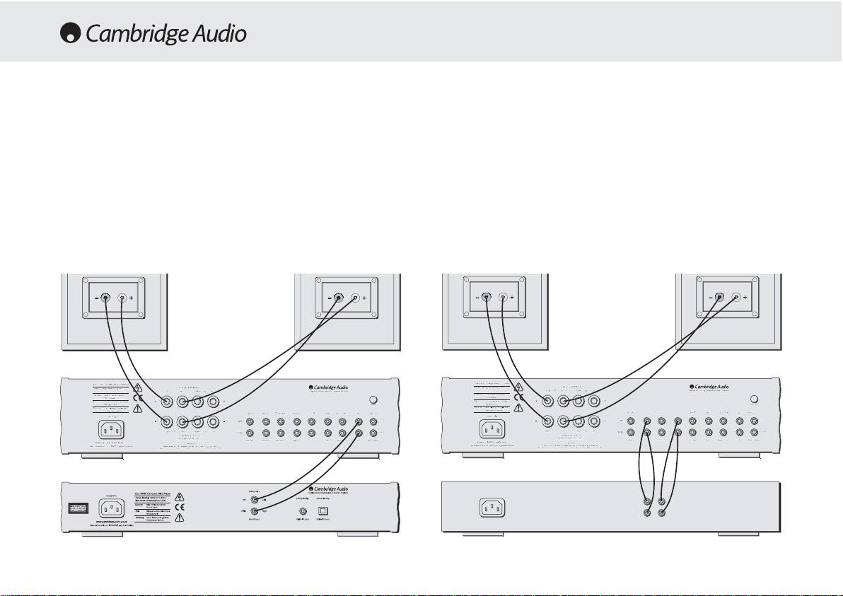
CONNECTING
When designing our amplifiers we have tried to include features that
Tape cconnection
allow you to connect your system in various ways. The inclusion of
features such as PRE-OUT and SPEAKER B connections mean that you
The following diagram shows how to connect the amplifier to a tape
can configure your system depending on your requirements. The
recorder or other source with a record and monitor connection.
following diagrams are designed to make connection easy.
Please note that either of the tape loop outputs can be used (as they are
both the same).
Basic cconnection
The following diagram shows the basic connection of your amplifier to a
CD player and a pair of loudspeakers.
8
M
ax Power
C
onsumption
:
615W
Pre-Ou
t
Pre-Out
Impedance 4 — 8 ohms
Impedance 4 — 8 ohms
Loudspeaker Terminals
Loudspeaker Terminals
Important
Important
P
lease ensure that loudspeaker terminals are fully tightened
Please ensure that loudspeaker terminals are fully tightened
Veuillez s’assurer que les bornes de l’enceinte sont entierement serrees
Veuillez s’assurer que les bornes de l’enceinte sont entierement serrees
Impedance 4 — 8 ohms
Impedance 4 — 8 ohms
R
ight
Right
Left
Left
R
ight
Right
L
ef
t
Left
L
eft
Left
B
B
A
A
Ri
g
h
t
Right
L
eft
Left
Right
Right
B
B
A
A
R
ec Out
1
Rec Out 1
R
ec Out
2
Rec Out 2
T
ape I
n
Tape In
AV / MD
AV / MD
DVD
DVD
Tuner / DAB
Tuner / DAB
CD
CD
A
ux / Phon
o
Aux / Phono
P
re-Out
Pre-Out
R
ec Out 1
Rec Out 1
R
ec Out
2
Rec Out 2
T
ape I
n
Tape In
AV
/
MD
AV / MD
DVD
DVD
Tuner / DAB
Tuner / DAB
C
D
CD
Aux / Phono
Aux / Phono
R
ight
Right
L
ef
t
Left
R
ight
Right
L
eft
Left
G
roun
d
Ground
w
ww.cambridge-audio.co.uk
www.cambridge-audio.co.uk
M
anufactured in an
Manufactured in an
ISO900
2
ISO9002
approved facilit
y
approved facility
P
ower AC
Power AC
D
esigned and Engineered in London, Englan
d
Designed and Engineered in London, England
R
isk of electric shock
Risk of electric shock
D
o not o
p
e
n
Do not open
Caut
i
on
Caution
Risque de choc electriqu
e
Risque de choc electrique
N
e
p
as ouvr
i
r
Ne pas ouvrir
A
v
is
Avis
Vorm offnen des gerates
Vorm offnen des gerates
N
etzstecker ziehe
n
Netzstecker ziehen
A
c
h
tun
g
Achtung
a
zur 6
4
0A Integrated Amplifier
azur 640A Integrated Amplifier
Power Rating:
Power Rating:
230V AC 50Hz
230V AC 50Hz
T
ape In
1
R
ec Out
1
Rec Out
2
T
ape In 1
R
ec Out 1
Rec Out
2
M
ax Power
C
onsumption
:
61
5W
Pre-Ou
tPre-Out
Impedance 4 — 8 ohms
Impedance 4 — 8 ohms
Loudspeaker Terminals
Loudspeaker Terminals
Important
Important
P
lease ensure that loudspeaker terminals are fully tightened
Please ensure that loudspeaker terminals are fully tightened
Veuillez s’assurer que les bornes de l’enceinte sont entierement serrees
Veuillez s’assurer que les bornes de l’enceinte sont entierement serrees
Impedance 4 — 8 ohms
Impedance 4 — 8 ohms
R
ight
Right
Left
Left
R
ight
Right
L
ef
t
Left
L
eft
Left
B
B
A
A
Ri
g
h
t
Right
L
eft
Left
Right
Right
B
B
A
A
AV / MD
AV / MD
DVD
DVD
Tuner / DAB
Tuner / DAB
CD
CD
A
ux / Phon
o
Aux / Phono
P
re-Out
Pre-Out
AV
/
MD
AV / MD
DVD
DVD
Tuner / DAB
Tuner / DAB
C
D
CD
Aux / Phono
Aux / Phono
R
ight
Right
L
ef
t
Left
R
ight
Right
L
eft
Left
G
roun
d
Ground
w
ww.cambridge-audio.co.uk
www.cambridge-audio.co.uk
M
anufactured in an
Manufactured in an
ISO900
2
ISO9002
approved facilit
y
approved facility
P
ower AC
Power AC
D
esigned and Engineered in London, Englan
d
Designed and Engineered in London, England
R
isk of electric shock
Risk of electric shock
D
o not o
p
e
n
Do not open
Caut
i
on
Caution
Risque de choc electriqu
e
Risque de choc electrique
N
e
p
as ouvr
i
r
Ne pas ouvrir
A
v
is
Avis
Vorm offnen des gerates
Vorm offnen des gerates
N
etzstecker ziehe
n
Netzstecker ziehen
A
c
h
tun
g
Achtung
a
zur 6
4
0A Integrated Amplifier
azur 640A Integrated Amplifier
Power Rating:
Power Rating:
230V AC 50Hz
230V AC 50Hz
Rec InRec Out
Tape // MMD Player
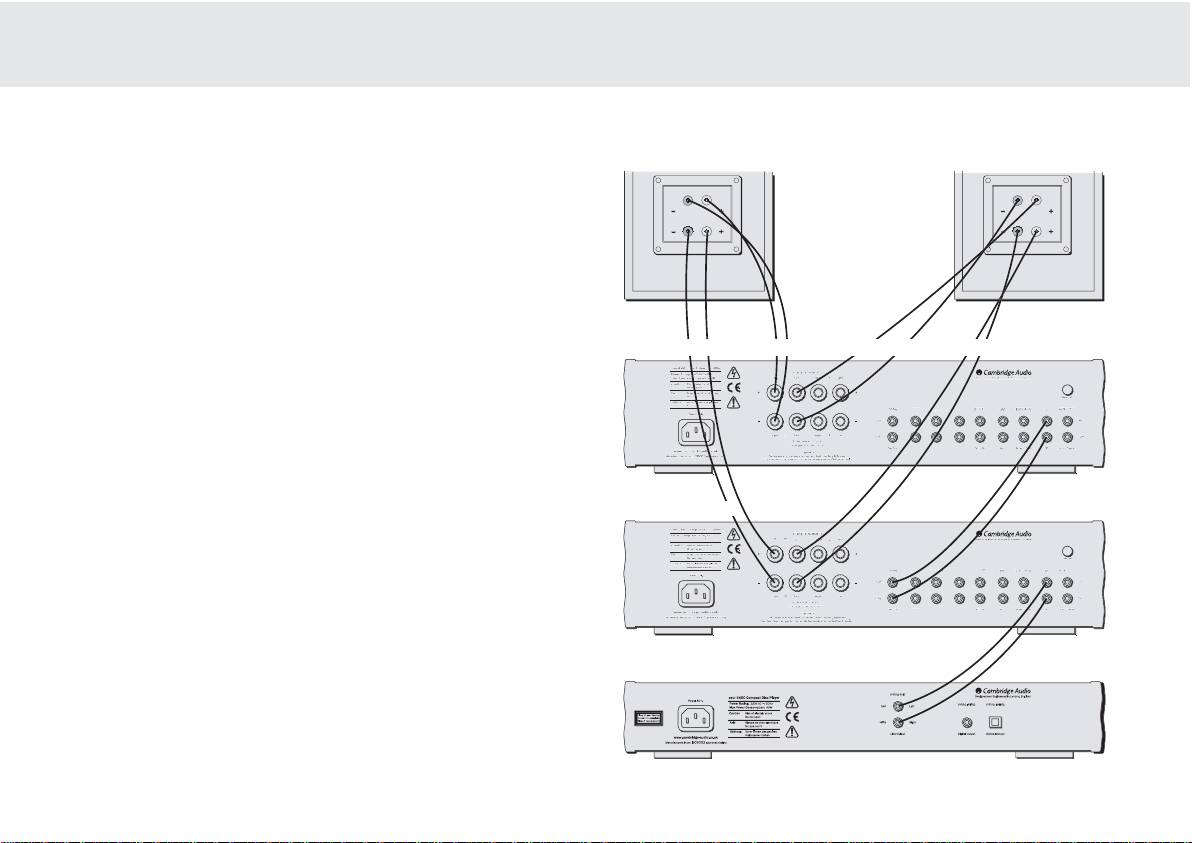
540A/640A Integrated amplifier
Bi-aamping
The azur amplifiers are equipped with PRE-OUT sockets. If your
loudspeakers have two sets of terminals then it is possible to bi-amp
your system using a further power amplifier. Bi-amping uses two
amplifiers to drive the bass and treble units in the loudspeakers
independently, resulting in even greater clarity coupled with improved
control and dynamics. An example of a bi-amp setup is illustrated in the
diagram adjacent.
Please note that if using a second azur amplifier as the slave amplifier,
any line input can be used to connect from the master’s Pre-Out.
Using SSpeaker BB connections
The Speaker B connections on the back of the amplifier allow a second
set of speakers to be used, which could be for another room.
9
Tape In
R
ec Out 1
R
ec Out
2
Tape In
R
ec Out
1
R
ec Out
2
M
ax Power
C
onsumptio
n
:
615
W
P
re-Out
Pre-Out
I
mpedance 4 — 8 ohms
Impedance 4 — 8 ohms
L
oudspeaker Terminals
Loudspeaker Terminals
Important
Important
P
lease ensure that loudspeaker terminals are fully tightened
Please ensure that loudspeaker terminals are fully tightened
Veuillez s’assurer que les bornes de l’enceinte sont entierement serrees
Veuillez s‘assurer que les bornes de l’enceinte sont entierement serrees
I
mpedance 4 — 8 ohm
s
Impedance 4 — 8 ohms
R
ight
Right
L
eft
Left
R
ight
Right
Left
Left
L
eft
Left
B
B
A
A
Ri
g
ht
Right
Left
Left
Right
Right
B
B
A
A
AV / MD
AV / MD
DVD
DVD
Tuner / DA
B
Tuner / DAB
C
D
CD
Aux / Phon
o
Aux / Phono
P
re-Out
Pre-Out
AV
/
MD
AV / MD
DVD
DVD
Tuner / DAB
Tuner / DAB
C
D
CD
Aux / Phon
o
Aux / Phono
Righ
t
Right
Left
Left
R
ight
Right
L
eft
Left
Groun
d
Ground
w
ww.cambridge-audio.co.uk
www.cambridge-audio.co.uk
M
anufactured in an
Manufactured in an
I
SO900
2
ISO9002
approved facilit
y
approved facility
P
ower A
C
Power AC
D
esigned and Engineered in London, England
Designed and Engineered in London, England
R
isk of electric shock
Risk of electric shock
D
o not o
p
en
Do not open
Caut
i
on
Caution
Risque de choc electriqu
e
Risque de choc electrique
N
e
p
as ouvr
i
r
Ne pas ouvrir
A
v
is
Avis
Vorm offnen des gerates
Vorm offnen des gerates
N
etzstecker ziehen
Netzstecker ziehen
Achtun
g
Achtung
azur 6
4
0A Integrated Amplifie
r
azur 640A Integrated Amplifier
Power Rating:
Power Rating:
230V AC 50Hz
230V AC 50Hz
Ta
p
e In
Rec Out 1
R
ec Out
2
T
ape I
n
Rec Out 1
Rec Out 2
P
re-Out
Pre-Out
I
m
p
edance 4 — 8 ohms
Impedance 4 — 8 ohms
L
oudspeaker Terminals
Loudspeaker Terminals
Important
Important
P
lease ensure that loudspeaker terminals are fully tightened
Please ensure that loudspeaker terminals are fully tightened
Veuillez s’assurer que les bornes de l’enceinte sont entierement serrees
Veuillez s’assurer que les bornes de l’enceinte sont entierement serrees
I
m
p
edance 4 — 8 ohm
s
Impedance 4 — 8 ohms
Ri
g
h
t
Right
L
eft
Left
Ri
g
h
t
Right
Left
Left
L
eft
Left
B
B
A
A
Righ
t
Right
Left
Left
Right
Right
B
B
A
A
AV
/
MD
AV / MD
DVD
DVD
Tuner
/
DA
B
Tuner / DAB
C
D
CD
Aux
/
Phon
o
Aux / Phono
P
re-Out
Pre-Out
AV
/
MD
AV / MD
DVD
DVD
T
uner
/
DAB
Tuner / DAB
C
D
CD
A
ux
/
Ph
on
o
Aux / Phono
Righ
t
Right
Left
Left
R
ight
Right
L
eft
Left
Groun
d
Ground
w
ww.cambridge-audio.co.uk
www.cambridge-audio.co.uk
M
anufactured in an
Manufactured in an
I
SO900
2
ISO9002
approved facility
approved facility
P
ower A
C
Power AC
D
esigned and Engineered in London, England
Designed and Engineered in London, England
R
isk of electric shock
Risk of electric shock
D
o not open
Do not open
C
autio
n
Caution
Ris
q
ue de choc electri
q
u
e
Risque de choc electrique
Ne pas ouvrir
Ne pas ouvrir
A
vi
s
Avis
Vorm offnen des gerates
Vorm offnen des gerates
N
etzstec
k
er z
i
e
h
en
Netzstecker ziehen
Achtun
g
Achtung
azur 6
4
0A Inte
g
rated Amplifie
r
azur 640A Integrated Amplifier
Power Rating:
Power Rating:
230V AC 50Hz
230V AC 50Hz
M
ax Power
C
onsumptio
n
Max Power Consumption
:
:
615
W
615W
Treble Treble
Bass Bass
Slave aamplifier
— if using an integrated amplifier, volume must be set to full
Master aamplifier
CD player
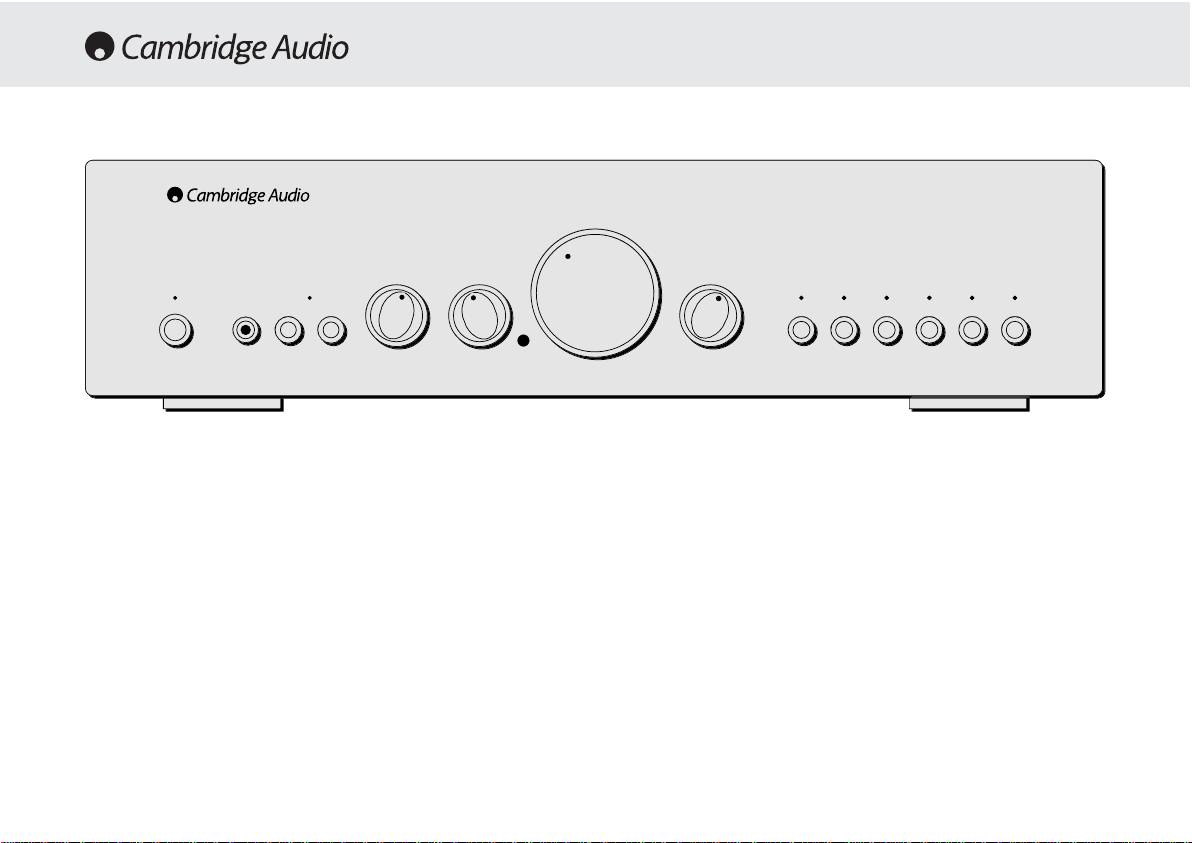
Standby/On
Please note that care should be taken when selecting if two
loudspeakers are going to be used on each channel. If the combined
Switches the unit between Standby mode (indicated by dim power LED)
resistance measured on the speaker terminals is too low the amplifier
and On (indicated by bright power LED). Standby is a low power mode
may not switch out of standby mode until a suitable load resistance is
where the power consumption is less than 10 Watts. The unit should be
detected. For more information please see section on CAP5 protection
left in standby when not in use.
system.
Note — WWhen uusing ttwo ppairs oof sspeakers eeach ppair sshould bbe rrated aat
Headphone ssocket
least 66 oohms ((or hhigher). 44 oohm
sspeakers aare nnot rrecommended wwhen
Allows for the connection of headphones with a ¼» Jack plug connector.
using mmore tthan oone ppair.
When the headphones are connected the loudspeaker relay is released
switching off the output to the loudspeakers (Speakers A and B).
Direct
This control gives the audio signal a more direct path to the power
Speaker BB oon/off
amplifier stage of your amplifier, bypassing the tone control circuits for
Enables/disables the secondary set of speaker terminals on the back
the purest possible sound quality.
panel. This can be used for listening to an extra set of speakers in
another room.
10
azur 640A
Integrated Amplifier
Volume
TrebleBass
Balance
Protection
Standby / On
Speaker BPhones
Direct
Aux / Phono
CD
DVD
AV / MDTuner / DAB
Tape Mon
OPERATING INSTRUCTIONS

540A/640A Integrated amplifier
Bass aand ttreble ttone ccontrols
Input sselection ppush bbuttons
These controls allow subtle adjustments to the tonal balance of the
Push the appropriate input selection button to select the source
sound. In the central position these controls have no effect. These
component that you wish to listen to. The signal selected is also fed to
controls only modify the sound through your loudspeakers and the Pre-
the Tape Out sockets so that it may be recorded. The input should not
Out sockets (where featured), they do not affect the signals sent through
be changed whilst recording, although the recorded signal can be
the Tape Out connections. With a well produced CD and a good system
checked using the tape input Tape monitor.
the tone controls are unnecessary and can be switched out. If the
musical recording is of poor quality and/or the
Tape mmonitor sselection bbutton
loudspeakers/surroundings are lacking it may be necessary to adjust
the tone controls to compensate.
This control lets you listen to the output signal from a tape recorder or
signal processor connected to the amplifier’s Tape monitor sockets.
When Tape monitor is selected, the source component chosen by the
Volume
input selection push buttons continues to be routed to the Tape Out
The Volume control increases/decreases the level of the sound from the
sockets for recording or processing.
outputs of the amplifier. This control affects the level of the Loudspeaker
output, the pre amp output and the headphone output. It does not affect
Remote ccontrol ooperation/features
the Tape Out Connections.
This Amplifier is supplied with a system remote control that operates
It is advisable to turn the Volume control fully anti-clockwise before
both this amplifier and the Cambridge Azur CD players. The functions
switching the amplifier on.
relevant to the amplifier are as follows:
Power —
Switches the amplifier between Standby mode and On mode.
Balance
Mute —
Mutes the audio (indicated by the input LED flashing).
This control allows you to adjust the relative output levels of the left and
right channels. In the central position the output from each channel is
Volume ++/—
— The volume buttons increase and decrease the Volume of
equal. This control only modifies the sound through your loudspeakers
the amplifier output.
and the Pre-Out sockets (where featured), it does not affect the signals
sent through the Tape Out connections.
Input sselect —
The five input select buttons and the Tape monitor select
button are used to change the input source.
11

CAP5 — FIVE WAY PROTECTION SYSTEM
Cambridge Audio has developed a proprietry protection system to
If the Loudspeaker impedance is low the temperature of the amplifier
ensure reliability and a long life to its amplifiers. This protection system
may rise faster as the amplifier is working harder. If the amplifier is
comprises of five main protection methods:
mounted in a cabinet or the ventilation slots are obstructed the over
temperature detection may activate/reactivate after a short listening
time.
Intelligent cclipping ddetection
CAP5 has the ability to detect when the amplifier starts to clip or
Short ccircuit ddetection
overdrive its output, which can damage Loudspeakers, the amplifier
power supply and most importantly degrade the sound. When CAP5
During power up from standby or during input channel selection CAP5
detects clipping the volume will be automatically nudged down until
performs a check on the Loudspeaker terminals to see if a short across
CAP5 detects an undistorted* output (*the volume is nudged down until
the terminals has been accidentally introduced. If the resistance
the distortion is less than 2% which listening tests have shown is
measured across the Loudspeaker terminals is too low the unit will stay
difficult to hear).
in Standby mode until the fault has been removed and Power up is re-
attempted.
It is possible to disable only this feature by holding down the Standby
button during power up (whilst plugging the unit into the mains power).
The unit will indicate this by flashing the protection LED for several
DC ddetection
seconds. Disabling the clipping detection is not advised as this feature
CAP5 offers Loudspeaker protection if the output of the amplifier goes
has been added to protect the amplifier.
to DC because of some internal fault. This is a rare fault although it
could just save those expensive Loudspeakers.
Over ttemperature ddetection
If the amplifier is switched out of standby when the input signal to the
CAP5 includes temperature detection which constantly monitors the
amplifier is too high (with the current volume setting) the CAP5 system
heat generated by the output transistors. When the monitored
will detect this and reduce the volume to a suitable level.
temperature reaches a high level (suitably within the limits of the output
devices) the amplifier will automatically switch into a fault mode
Overvoltage/overcurrent ddetection
(indicated by double flashing of the protection LED). The unit should
ideally be left for 15 minutes in this state to cool down adequately. If the
CAP5 offers V/I protection by constantly monitoring the output
unit has not fully cooled down then the temperature may reach the limit
transistors to keep them working inside their Safe Operating Area (SOA).
soon after the amplifier is powered up.
The SOA is a set of limits given by the output transistor manufacturer to
ensure reliability. Many amplifier designers include V/I limiting in the
12
540A/640A Integrated amplifier
signal path which can degrade the signal by compressing dynamics. The
CAP5 system operates outside the signal path and when triggered shuts
down the amp rather than limits the size of the signal passing through
the amp (signal compression). V/I protects the amplifier against short
circuits on the speaker terminals during use.
Indication
Fault/Remedy
Protection LED flashes for 4 seconds when unit attempts to come out of
CAP5 has detected that the resistance on the Loudspeaker terminals is
Standby mode.
too low. Check to see if there is a short circuit between the Loudspeaker
terminals.
Note: If the indication remains the same and multiple Loudspeakers are
being used on each Loudspeaker output then please remove a pair and
retry. If too many Loudspeakers are connected to any amplifier causing
the Load resistance to drop too low the amplifier will overheat. CAP5 will
detect this situation.
If the indication remains the same with only one set of loudspeakers
connected then there could possibly be a fault with one or both of the
loudspeakers.
Unit has switched off during operation. Protection LED constantly
ddoouubbllee
CAP5 has detected a user related fault, the internal temperature of the
ffllaasshheess..
output transistors has reached the over temperature limit. The unit is not
damaged although it should be left for 15 minutes to cool down before
being switched out of standby.
Unit has switched off during operation. Protection LED constantly
ffllaasshheess
CAP5 has detected a user related fault, there maybe a short circuit
oonn aanndd ooffff iinn bbuurrssttss ooff 44
.
between the loudspeaker terminals. Please check all Loudspeaker
connections before attempting to switch unit out of standby
Unit has switched off during operation. Protection LED is
oonn wwiitthh aa bbrriieeff
CAP5 has detected a fault which requires the unit to be serviced. DC has
ooffff ffllaasshh
.
been detected on the output of the amplifier which could damage the
speakers. The amplifier is now unusable. Please switch off and contact
dealer.
13

TROUBLESHOOTING
SPECIFICATIONS
There iis nno ppower
540A 640A
Ensure the AC power cord is connected securely.
Ensure the plug is fully inserted into the wall socket and is switched on.
Check fuse in the mains plug or adaptor
Power OOutput
75W (into 4Ω)
100W (into 4Ω)
50W (into 8Ω)
65W (into 8Ω)
There iis nno ssound
Make sure the unit is not in Standby mode
Max PPower
Check that source component is properly connected
Consumption
515W
615W
Check that ‘TAPE MON’ is not switched on (unless tape input is required)
Check that your speakers are properly connected
Standby PPower
If using Speaker B terminals check they are switched on
If channel LED is flashing turn mute off
Consumption
6W
6W
There iis nno ssound oon oone cchannel
THD (unweighted)
1kHz < 0.009%
1kHz < 0.005%
Ensure that balance control is in the correct position
Check speaker connections
20kHz < 0.09%
20kHz < 0.07%
Check interconnects
There iis aa lloud bbuzz oor hhum
Freq RResponse
(-33dB)
5Hz — 50kHz
4Hz — 80kHz
Check turntable or tone arm for ground and connection lead fault
Ensure no interconnects are loose or defective
S tto NN RRatio
(unweighted)
92dB
92dB
Ensure that your tape deck/turntable is not too close to the amplifier
Unable tto mmake oor pplay ttape rrecordings
Slew RRate
(into 88ΩΩ)
30V/uS
50V/uS
Check that TAPE MON and TAPE OUT have been connected correctly
There iis wweak bbass oor ddiffused sstereo iimaging
Dimensions
(HxWxD)
Ensure that speakers are not wired out of phase
mm
100 x 430 x 310
100 x 430 x 310
Will nnot sswitch oout oof sstandby — pprotection LLED flashing
inches
3.9 x 16.9 x 12.2
3.9 x 16.9 x 12.2
Please see section on CAP5 protection system
Weight
Protection LLED flashing
Please see section on CAP5 protection system (page 12)
kg
7
7
Lbs
15.4
15.4
14

540A/640A Integrated amplifier
LIMITED WARRANTY
Cambridge Audio warrants this product to be free from defects in
Cambridge Audio dealer, or authorised service agent which is authorised
materials and workmanship (subject to the terms set forth below).
to do Cambridge Audio warranty work. Any unauthorised repairs will void
Cambridge Audio will repair or replace (at Cambridge Audio’s option) this
this Warranty. This Warranty does not cover products sold AS IS or WITH
product or any defective parts in this product. Warranty periods may vary
ALL FAULTS.
from country to country. If in doubt consult your dealer and ensure that
you retain proof of purchase.
REPAIRS OR REPLACEMENTS AS PROVIDED UNDER THIS WARRANTY
ARE THE EXCLUSIVE REMEDY OF THE CONSUMER. CAMBRIDGE AUDIO
To obtain warranty service, please contact the Cambridge Audio
SHALL NOT BE LIABLE FOR ANY INCIDENTAL OR CONSEQUENTIAL
authorised dealer from which you purchased this product. If your dealer
DAMAGES FOR BREACH OF ANY EXPRESS OR IMPLIED WARRANTY IN
is not equipped to perform the repair of your Cambridge Audio product,
THIS PRODUCT. EXCEPT TO THE EXTENT PROHIBITED BY LAW, THIS
it can be returned by your dealer to Cambridge Audio or an authorised
WARRANTY IS EXCLUSIVE AND IN LIEU OF ALL OTHER EXPRESS AND
Cambridge Audio service agent. You will need to ship this product in
IMPLIED WARRANTIES WHATSOEVER INCLUDING, BUT NOT LIMITED TO,
either its original packaging or packaging affording an equal degree of
THE WARRANTY OF MERCHANTABILITY AND FITNESS FOR A PRACTICAL
protection.
PURPOSE.
Proof of purchase in the form of a bill of sale or receipted invoice, which
Some countries and US states do not allow the exclusion or limitation of
is evidence that this product is within the warranty period, must be
incidental or consequential damages or implied warranties so the above
presented to obtain warranty service.
exclusions may not apply to you. This Warranty gives you specific legal
rights, and you may have other statutory rights, which vary from state to
This Warranty is invalid if (a) the factory-applied serial number has been
state or country to country.
altered or removed from this product or (b) this product was not
purchased from a Cambridge Audio authorised dealer. You may call
Cambridge Audio or your local country Cambridge Audio distributor to
confirm that you have an unaltered serial number and/or you purchased
from a Cambridge Audio authorised dealer.
This Warranty does not cover cosmetic damage or damage due to acts
of God, accident, misuse, abuse, negligence, commercial use, or
modification of, or to any part of, the product. This Warranty does not
cover damage due to improper operation, maintenance or installation,
or attempted repair by anyone other than Cambridge Audio or a
15

EINLEITUNG
Vielen DDank, ddass SSie ssich ffür ddie AAnschaffung eeines CCambridge AAudio—
Ringkern-Transformatoren, parallel geschaltete Speicherkondensatoren
Verstärkers aaus dder AAzur-SSerie e
entschieden hhaben. DDieses GGerät iist ddas
sowie Bypass-Kondensatoren garantieren jederzeit eine saubere,
Resultat uunserer bbis hheute aaufwendigsten FForschung uund EEntwicklung.
dynamische Stromversorgung. Dies wiederum ermöglicht ein
Wir wwünschen IIhnen mmit ddiesem EErgebnis llangjährige FFreude.
kraftvolles, dynamisches Klangbild voller natürlicher Details und Fülle.
Besondere Aufmerksamkeit wurde der Auswahl passiver Bauteile
gewidmet, welche insbesondere nach klanglichen Kriterien ausgewählt
Einige DDetails
wurden. Im Azur 640A kommen zudem spezielle Polypropylen-
Planung und Entwicklung jedes puristischen Hifi-Verstärker-Konzepts
Kondensatoren zum Einsatz, insbesondere an klanglich sensiblen
konzentriert sich im Wesentlichen auf zwei Baugruppen, die
Punkten im Signalweg.
Stromversorgung und eine möglichst effiziente Treiberstufe
Hifi-Puristen können das Klangregelnetzwerk des Azur 540A / 640A bei
(Vorverstärker) zur Ansteuerung der Leistungstransistoren, also der
Bedarf komplett überbrücken. Es wird somit vollständig aus dem
eigentlichen Endstufe. Dem Cambridge Audio Entwickler-Team ist es
Signalweg entfernt. Der Anschluß eines Kopfhörers ist ebenfalls
gelungen, in diesen beiden wichtigen Bereichen die bestmögliche
möglich. Er wird direkt aus der kraftvollen Endstufe gespeist.
Lösung zu finden, um technisch Machbares in einem bisher nicht
dagewesenen Preis-/Leistungsverhältnis zu realisieren. Die bewährten
Eine neu entwickelte innovative Schutzschaltung, das Cambridge Audio
Leistungstransistoren der Verstärker Azur 540A / 640A kamen schon in
CAP5 System , schützt die Verstärker Azur 540A / 640A vor einer
den äußerst erfolgreichen Vorgänger-Modellen zum Einsatz. Die
Vielzahl möglicherweise auftretenden Defekte oder Fehlbedienungen.
vorgeschalteten Verstärker-Stufen wurden jedoch komplett neu
Dies geschieht durch prozessorgesteuerte Überwachung, ohne
entwickelt.
zusätzliche aktive Bauteile im Signalweg.
Auf Grund des überaus durchdachten Layouts, sorgfältig plazierter
All unser Wissen und langjährige Erfahrung haben wir in die neue Azur
Bauteile und kurzer Signalwege ergibt sich eine extrem hohe Stabilität
Generation einfließen lassen. Mit viel Liebe zum Detail entstanden Hifi-
der Verstärkerschaltung. Kompensationsschaltungen können somit auf
Verstärker, die klanglich wegen ihrer hohen Auflösung und Dynamik
ein Minimum reduziert werden. Verzerrungen können drastisch
überzeugen. Sie begeistern durch eine lebhafte, fließende Darbietung
reduziert werden. Dynamik und auch die Bandbreite von 80 kHz (!) —
jeder Art von Musik. Diese Verstärker beziehen den Hörer ins
wünschenswert für die hochauflösenden Formate wie DVD-Audio und
Klanggeschehen voll ein!
SACD — werden den Anforderungen neuer Medien gerecht.
Um das musikalische Potential dieses Gerätes voll ausschöpfen zu
Der Klang und die Performance eines Hifi-Verstärkers werden sehr oft
können, empfehlen wir sehr, bei der Auswahl der übrigen Komponenten
durch eine begrenzte Dynamik der Stromversorgung limitiert. Kräftige
Ihrer Stereoanlage auf ebenso hohe Qualität zu achten. Natürlich raten
16

540A/640A HIFI-Verstärker
INHALT
wir zu den weiteren Komponenten unserer Cambridge Audio Azur-Line.
Einleitung………………………………………………………………………………………16
Denn diese sind auf demselben hohen Niveau wie Ihr neuer Verstärker
Sicherheitshinweise……………………………………………………………………….18
entwickelt worden.
Installation…………………………………………………………………………………… 19
Darüber hinaus sollten Sie auf eine hochwertige Verkabelung Ihrer
Geräte und Lautsprecher achten. Die Verwendung minderwertiger
Anschlüsse auf der Geräterückseite……………………………………………….20
Verbindungs- und Lautsprecherkabel limitiert die klanglichen
Fähigkeiten Ihres Wiedergabesystems, welches immer nur so gut sein
Hilfe zum Anschluß Ihrer Komponenten…………………………………………..22
kann, wie sein schwächstes Glied in der Kette. Aus diesem Grund legen
Bedienungshinweise………………………………………………………………………24
wir unseren Geräten keine «Billig-Beipack-Kabel» bei. Ihr Händler bietet
Ihnen Cambridge Audio Kabel, die garantieren, dass Ihre Hifi-Anlage ihr
CAP5 — Schutzschaltung………………………………………………………………….26
ganzes Potential entfaltet.
Problembehandlung………………………………………………………………………28
Nun lladen wwir SSie eein, ssich zzurückzulehnen uund MMusik eentspannt zzu
Technische Daten………………………………………………………………………….28
genießen!
Haftungsbeschränkung………………………………………………………………… 29
Matthew Bramble
Technical Director
17

SICHERHEITSHINWEISE
Überprüfung dder NNetzspannung
Zu Ihrer eigenen Sicherheit bitten wir Sie, die folgenden Hinweise
sorgfältig zu lesen, bevor Sie dieses Gerät mit dem Stromnetz
verbinden.
Stellen Sie sicher, dass die Netzspannungsangabe auf der
Geräterückseite mit der Höhe der Netzspannung vor Ort übereinstimmt.
Nur bei Übereinstimmung ist ein fehlerfreier, sicherer Betrieb
gewährleistet. Der Anschluss an abweichende Netzspannungen als am
Gerät angegeben kann zu erheblichen Beschädigungen führen.
Wird das Gerät über einen längeren Zeitraum nicht benutzt, so sollte es
vom Stromnetz getrennt werden. Verwenden Sie zum Anschluss nur das
beiliegende Netzkabel oder andere hochwertige Kabel mit
Erdungskontakt! Der Kontakt mit der Netzspannung ist
lebensgefährlich! Öffnen Sie niemals das Gehäuse, sondern überlassen
Sie dieses qualifiziertem Servicepersonal.
Dieses Zeichen warnt vor nicht isolierten Bereichen. Bei
unqualifizierter Lightning flash Handhabung besteht die
Gefahr eines elektrischen Schlags.
Wichtige Hinweise sind im Folgenden mit diesem Zeichen
gekennzeichnet:
Dieses Gerät entspricht den europäischen
Standards für Sicherheit (73/23/EEC) und
elektromagnetischer Verträglichkeit (89/336/EEC),
sofern alle Hinweise in dieser Anleitung beachtet
werden. Aus diesem Grunde dürfen bei eventuellen
Reparaturen nur Originalersatzteile von Cambridge Audio
verwendet werden. Bei Nichtbeachtung und/oder Modifikationen
jeglicher Art erlischt jeder Gewährleistungsanspruch!
18

540A/640A HIFI-Verstärker
INSTALLATION
Bitte nehmen Sie sich einen Moment Zeit, um die folgenden Hinweise zu
Sollte der Verstärker jedoch für längere Zeit nicht benutzt werden,
lesen, bevor Sie Ihren Azur Verstärker anschließen. Dies wird Ihnen
empfehlen wir die komplette Trennung vom Stromnetz durch
ermöglichen, sichere Betriebsbedingungen zu schaffen, sowie ein
Herausziehen des Netzsteckers aus der Steckdose.
Optimum an Klang und Leistung zu gewährleisten.
Zur Reinigung des Azur Verstärkers verwenden Sie bitte ein leicht
Stellen Sie den Verstärker auf eine feste, ebene Standfläche. Das Gerät
feuchtes, Fussel freies Tuch. Benutzen Sie niemals aggressive
benötigt eine ausreichende Belüftung. Stellen Sie es deshalb nicht auf
Reinigungsmittel welche z.B. Alkohol, Ammoniak oder Scheuermittel
einen Teppich oder eine andere weiche Unterlage, und verdecken Sie
enthalten. Benutzen Sie auch keine Sprays am Verstärker, oder in seiner
nicht die Lüftungsschlitze. Stellen Sie das Gerät nicht in ein
Nähe.
geschlossenes Fach oder in einen geschlossenen Schrank.
Es befinden sich keinerlei Einstellungsmöglichkeiten im Inneren des
Schützen Sie das Gerät vor jeglichem Kontakt mit Wasser oder anderen
Gerätes, welche durch den Benutzer verändert werden können, um die
Flüssigkeiten. Stellen Sie sicher, daß keine kleineren Gegenstände in
Wiedergabe in irgendeiner Weise zu beeinflussen! Ein eventuell
die Belüftungsschlitze fallen können. Sollte solch ein Fall trotzdem
notwendiger Eingriff in das Gerät sollte ausschließlich autorisiertem
einmal eintreten, schalten Sie bitte das Gerät sofort aus! Ziehen Sie den
Fachpersonal vorbehalten sein. Versuchen Sie niemals das Gerät zu
Stecker, und fragen Sie gegebenenfalls ihren Händler um Rat.
öffnen. Der Kontakt mit der Netzspannung ist lebensgefährlich! Bei
Auftauchen eines Problems oder Fehlers wenden Sie sich bitte zuerst an
Verlegen Sie das Netzkabel sorgfältig! Vermeiden Sie, daß andere
Ihren Händler.
Gegenstände oder Geräte darauf stehen oder es beschädigen können.
Da das Netzteil des Verstärkers ein leichtes Magnetfeld erzeugt, sollte
ein eventuell angeschlossener Plattenspieler nicht in unmittelbarer
Nähe stehen.
Wie alle audiophilen Hifi-Produkte benötigt auch Ihr Azur Verstärker eine
gewisse Einspielzeit. Abhängig von der täglichen Betriebsdauer beträgt
diese ca. 1-2 Wochen. Kondensatoren und einige aktive Bauteile
benötigen diese Zeit der «Formatierung», um ihr volles Klangpotential zu
erreichen.
Die Verstärker Azur 540A / 640A können in Betriebspausen, in denen
keine Musik gehört wird, in den Standby Modus geschaltet werden.
19

230-2240Volt AAnschluß
Lautsprecherkabel entsprechend der Zuordnung zu Ihren
Lautsprechern mit den Terminals Right (Rechts) + & — und Left (Links) +
Bevor Sie den Verstärker mittels des beiliegenden Netzkabels mit dem
& — der Lautsprechergruppe A und/oder B. Achten Sie bitte besonders
Stromnetz verbinden, stellen Sie bitte zunächst alle Verbindungen zu
auf gute und feste Verbindungen, und stellen Sie sicher das kein
weiteren Hifi Geräten und den Lautsprechern her. Nach Einstecken des
Kurzschluß zwischen + & — bzw. von den Anschlüssen zur
Netzkabels sollten Sie einen kurzen «Systemcheck» vornehmen. Dabei
Geräterückwand entstehen kann. Gute Lautsprecherkabel und
werden alle Anzeigen auf der Gerätefront kurz aufleuchten.
Kontakte verbessern den Klang und die Leistungsfähigkeit Ihres
Abschließend geht der Verstärker in den Standby Modus und ist nun
Verstärkers!
betriebsbereit.
Achtung: DDie AAzur 5540A // 6640A VVerstärker ssind ffür LLautsprecher—
Impedanzen vvon 44-88 OOhm aausgelegt. E
Entsprechende HHinweise bbefinden
Lautsprecher AAnschlüsse
sich iin dder RRegel aauf ddem AAnschlußfeld IIhrer LLautsprecher. IIm
Auf der Rückseite der Azur 540A / 640A Verstärker befinden sich die
Zweifelsfall zziehen SSie bbitte IIhren HHändler zzu RRate.
Lautsprecher-Anschlüsse A und B. Gruppe A ist die Hauptlautsprecher-
Achtung: AAlle iim FFolgenden bbeschriebenen AAnschlüsse ssind a
analoge EEin—
Gruppe und nicht schaltbar. Gruppe B ist mit einem entsprechenden
bzw. AAusgänge uund ddürfen nnie mmit ddigitalen AAus— bbzw. EEingängen
Schalter an der Gerätefront zu- oder abschaltbar. Verbinden Sie nun die
verschiedener GGeräte vverbunden wwerden!
20
T
ape In
R
ec Out 1
R
ec Out
2
T
ape In
R
ec Out 1
Rec Out
2
M
ax Power Consum
p
tion
:
615W
P
re-Out
Pre-Out
I
mpedance
4
— 8 ohms
Impedance 4 — 8 ohms
L
oudspeaker Terminals
Loudspeaker Terminals
Important
Important
P
lease ensure that loudspeaker terminals are fully tightened
Please ensure that loudspeaker terminals are fully tightened
Veuillez s’assurer que les bornes de l’enceinte sont entierement serreesVeuillez s‘assurer que les bornes de l’enceinte sont entierement serrees
I
mpedance 4 — 8 ohms
Impedance 4 — 8 ohms
R
ight
Right
L
eft
Left
R
ight
Right
L
eft
Left
Left
Left
B
B
A
A
R
ight
Right
L
eft
Left
R
ight
Right
B
B
A
A
AV / MD
AV / MD
DVD
DVD
T
uner / DAB
Tuner / DAB
CD
CD
Aux / Phon
o
Aux / Phono
P
re-Out
Pre-Out
AV / MD
AV / MD
D
VD
DVD
Tuner / DAB
Tuner / DAB
C
D
CD
A
ux / Phono
Aux / Phono
R
ight
Right
L
eft
Left
Ri
g
h
t
Right
L
eft
Left
Groun
d
Ground
w
ww.cambridge-audio.co.u
k
www.cambridge-audio.co.uk
M
anufactured in an
Manufactured in an
I
SO900
2
ISO9002
approved facility
approved facility
P
ower A
C
Power AC
D
esigned and Engineered in London, England
Designed and Engineered in London, England
R
isk of electric shoc
k
Risk of electric shock
D
o not ope
n
Do not open
C
aution
Caution
Ris
q
ue de choc electri
q
ue
Risque de choc electrique
Ne
p
as ouvrir
Ne pas ouvrir
Avis
Avis
Vorm offnen des geratesVorm offnen des gerates
N
etzstecker ziehen
Netzstecker ziehen
Achtung
Achtung
a
zur 6
4
0A Integrated Amplifie
r
azur 640A Integrated Amplifier
Power Rating:
Power Rating:
230V AC 50Hz
230V AC 50Hz
ANSCHLÜSSE AUF DER GERÄTERÜCKSEITE
Оглавление
Аннотация для Ресивера/Усилителя Cambridge Audio Azur 640A в формате PDF
Топ 10 инструкций
Другие инструкции