

3029
4039, 4045
6059, 6068
Engines (Saran)
( -499999CD)
COMPONENT
TECHNICAL
MANUAL
r
John Deere Usine de Saran
CTM3274 (01JUL99)
European Version
Printed in Germany
ANGLAIS

3029, 4039, 4045, 6059, 6068
Engines (Saran)
( -499999CD)
CTM3274 (01JUL99)

FOREWORD
Introduction
This manual is written for an experienced technician.
Essential tools required in performing certain service
work are identified in this manual and are
recommended for use.
Live with safety: Read the safety messages in the
introduction of this manual and the cautions
presented throughout the text of the manual.
This is the safety-alert symbol. When you see
N
this symbol on the machine or in this manual,
be alert to the potential for personal injury.
Use this component technical manual in conjunction
with the machine technical manual. An application
listing in the introduction identifies
product-model/component type-model relationship.
See the machine technical manual for information on
component removal and installation, and gaining
access to the components.
This manual is divided in two parts: repair and
operation and tests. Repair sections contain
necessary instructions to repair the component.
Operation and tests sections help you identify the
majority of routine failures quickly.
Information is organized in groups for the various
components requiring service instruction. At the
beginning of each group are summary listings of all
applicable essential tools, service equipment and
tools, other materials needed to do the job, service
parts kits, specifications, wear tolerances, and torque
values.
Component Technical Manuals are concise service
guides for specific components. Component technical
manuals are written as stand-alone manuals covering
multiple machine applications.
Fundamental service information is available from
other sources covering basic theory of operation,
fundamentals of troubleshooting, general
maintenance, and basic type of failures and their
causes.
DX,CTMIFC -19-22MAY92
CTM3274 (01JUL99) Saran Liter Engines
060799
PN=3
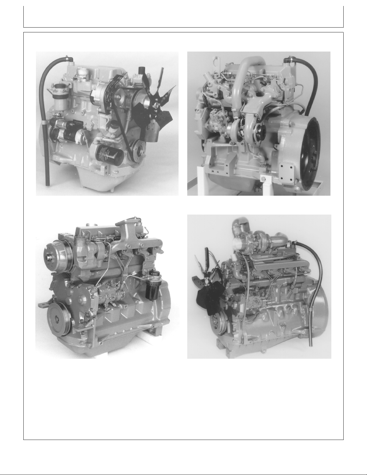
ENGINE IDENTIFICATION VIEWS
Introduction
CD30699 -UN-23FEB99
3029D 3029T
CD30701 -UN-23FEB99
4039D 4039T
CD30518 -UN-19MAY98
CD30702 -UN-23FEB99
CD,3274,G00,27 -19-04JAN99
CTM3274 (01JUL99) Saran Liter Engines
060799
PN=4
Introduction
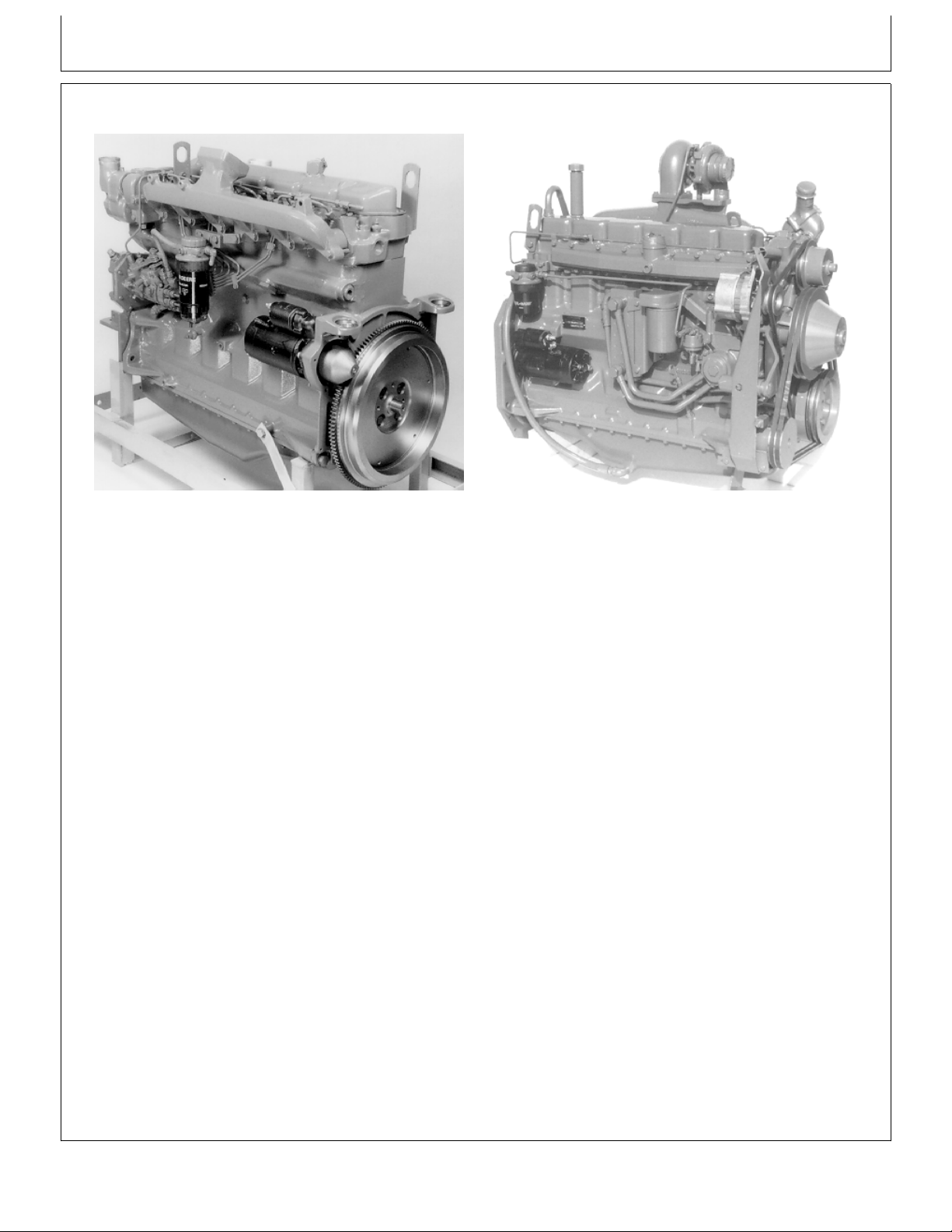
ENGINE IDENTIFICATION VIEWS (CONT’D)
CD30703 -UN-23FEB99
6068D 6068H
CD30704 -UN-23FEB99
CD,3274,G00,28 -19-04JAN99
CTM3274 (01JUL99) Saran Liter Engines
060799
PN=5

Engine application chart
This Component Technical Manual contains service
information on the 3029, 4039, 4045, 6059 and 6068
engines produced by JOHN DEERE Saran (FRANCE)
NOTE: Information on how to remove and reinstall
the engine in the vehicle is contained in the
relevant Technical Manual.
for the applications listed in the application chart.
3000-SERIES TRACTORS ENGINE MODEL SERIAL NUMBER
3100 . . . . . . . . . . . . . . . . . . . . . . . . CD3029DRT65 (189846 — )
3110 . . . . . . . . . . . . . . . . . . . . . . . . CD3029DRT65
3200/3200X . . . . . . . . . . . . . . . . . . . . CD4039DRT35 (181345 — )
3210/3210X . . . . . . . . . . . . . . . . . . . . CD4039DRT35
3300/3300X . . . . . . . . . . . . . . . . . . . . CD4045DRT35 (182145 — )
3310/3310X . . . . . . . . . . . . . . . . . . . . CD4045DRT35
3400/3400X . . . . . . . . . . . . . . . . . . . . CD4039TRT35 (181775 — )
3410/3410X . . . . . . . . . . . . . . . . . . . . CD4039TRT35
4000-SERIES TELESCOPIC ENGINE MODEL SERIAL NUMBER
HANDLERS
4400 . . . . . . . . . . . . . . . . . . . . . . . . CD4039TF005 (237697 — )
4500 . . . . . . . . . . . . . . . . . . . . . . . . CD4039TF005
5000-SERIES TRACTORS ENGINE MODEL SERIAL NUMBER
(Agritalia-built)
5300/5300N . . . . . . . . . . . . . . . . . . . . CD3029DAT01 (315424 — )
5400/5400N . . . . . . . . . . . . . . . . . . . . CD3029TAT02 (289398 — )
5500/5500N . . . . . . . . . . . . . . . . . . . . CD4039TAT01 (346168 — )
5000-SERIES TRACTORS ENGINE MODEL SERIAL NUMBER
(Augusta-built)
5400N . . . . . . . . . . . . . . . . . . . . . . . CD3029TLV01
5500N . . . . . . . . . . . . . . . . . . . . . . . CD4039TLV01 (201353 — )
5000-SERIES TRACTORS ENGINE MODEL SERIAL NUMBER
(For India)
5300 . . . . . . . . . . . . . . . . . . . . . . . . CD3029DPY01 (383283 — )
(Continued on next page)
CD,3274,G00,24 -19-04JAN99
CTM3274 (01JUL99) Saran Liter Engines
060799
PN=6

Engine application chart
ENGINE APPLICATION CHART (CONT’)
6000-SERIES TRACTORS ENGINE MODEL SERIAL NUMBER
6100 (Direct fan drive) . . . . . . . . . . . . CD4045DL001 (101582 — )
6100 (Viscous fan drive) . . . . . . . . . . . CD4045DL002 (101582 — )
6200 (Direct fan drive) . . . . . . . . . . . . CD4039TL001 (101625 — )
6200 (Viscous fan drive) . . . . . . . . . . . CD4039TL004 (101625 — )
6300 (Direct fan drive) . . . . . . . . . . . . CD4039TL003 (101649 — )
6300 (Viscous fan drive) . . . . . . . . . . . CD4039TL006 (101649 — )
6400 (Direct fan drive) . . . . . . . . . . . . CD4045TL001 (101682 — )
6400 (Viscous fan drive) . . . . . . . . . . . CD4045TL003 (101682 — )
6506 (Viscous fan drive) . . . . . . . . . . . CD6068DL001 (214852 — )
6600 (Viscous fan drive) . . . . . . . . . . . CD6059TL001 (128886 — )
6800 (Viscous fan drive) . . . . . . . . . . . CD6068TL001 (124505 — )
6900 (Viscous fan drive) . . . . . . . . . . . CD6068TL002 (186326 — )
WATERLOO TRACTORS ENGINE MODEL SERIAL NUMBER
7600 . . . . . . . . . . . . . . . . . . . . . . . . T06068TRW01
ZWEIBRÜCKEN COMBINES ENGINE MODEL SERIAL NUMBER
2054 . . . . . . . . . . . . . . . . . . . . . . . . 6068HZ001 (116452 — )
2254 . . . . . . . . . . . . . . . . . . . . . . . . 6068HZ001
ENGINES FOR CHINESE COMBINES SERIAL NUMBER
CD6059TYC01 . . . . . . . . . . . . . . . . . . . . . . . . . . . . (367019 — )
CD6059TYC02 . . . . . . . . . . . . . . . . . . . . . . . . . . . . (363170 — )
ENGINES FOR GOLDONI TRACTORS SERIAL NUMBER
CD3029DFG21 . . . . . . . . . . . . . . . . . . . . . . . . . . . . (287123 — )
CD3029DFG22 . . . . . . . . . . . . . . . . . . . . . . . . . . . . (287325 — )
CD3029TFG21 . . . . . . . . . . . . . . . . . . . . . . . . . . . . (287526 — )
(Continued on next page)
CD,3274,G00,25 -19-04JAN99
CTM3274 (01JUL99) Saran Liter Engines
060799
PN=7

Engine application chart
ENGINE APPLICATION CHART (CONT’)
SARAN OEM ENGINES SERIAL NUMBER SARAN OEM ENGINES SERIAL NUMBER
CD3029DF CD3029TF
CD3029DF001 CD3029TF001
CD3029DF005 (162670 — ) CD3029TF002 (170797 — )
CD3029DF031 CD3029TF031
CD3029DF032 CD3029TF032 (176015 — )
CD3029DF033 (177875 — ) CD3029TF033 (177880 — )
CD3029DF034 CD3029TF120
CD3029DF120 CD3029TF121
CD3029DF121 CD3029TF123 (354029 — )
CD3029DF122 (263024 — ) CD3029TF160
CD3029DF123 (312932 — ) CD3029TF161 (288419 — )
CD3029DF124 (340207 — ) CD3029TF162
CD3029DF128 CD3029TF163 (342829 — )
CD3029DF160
CD3029DF161 (288417 — )
CD3029DF162
CD3029DF163
CD3029DF164
CD3029DF165
CD4039DF CD4039TF
CD4039DF001 CD4039TF001
CD4039DF002 CD4039TF002
CD4039DF004 (152613 — ) CD4039TF003 (169516 — )
CD4039DF005 (165009 — ) CD4039TF004 (152616 — )
CD4039DF006 (340212 — ) CD4039TF005
CD4039DF007 (378895 — ) CD4039TF006 (339780 — )
CD4039DF008 CD4039TF007 (379066 — )
CD4039DF031 CD4039TF008
CD4039DF032 CD4039TF031
CD4039TF032 (166826 — )
CD4045DF001 CD4045TF001
CD4045DF031 CD4045TF002 (170081 — )
CD4045TF003 (342250 — )
CD4045TF008
CD4045TF031
(Continued on next page)
CD,3274,G00,29 -19-04JAN99
CTM3274 (01JUL99) Saran Liter Engines
060799
PN=8

Engine application chart
ENGINE APPLICATION CHART (CONT’)
SARAN OEM ENGINES SERIAL NUMBER SARAN OEM ENGINES SERIAL NUMBER
CD6059DF CD6059TF
CD6059DF001 CD6059TF001
CD6059DF002 CD6059TF002 (158390 — )
CD6059DF003 CD6059TF003 (158394 — )
CD6059TF004
CD6059TF005 (166159 — )
CD6059TF006 (166960 — )
CD6059TF008 (341217 — )
CD6068DF001 CD6068TF001
CD6068TF002 (187378 — )
CD6068TF003
CD6068TF004 (344260 — )
CD6068TF008
CD6068TF009
CD,3274,G00,30 -19-04JAN99
CTM3274 (01JUL99) Saran Liter Engines
060799
PN=9
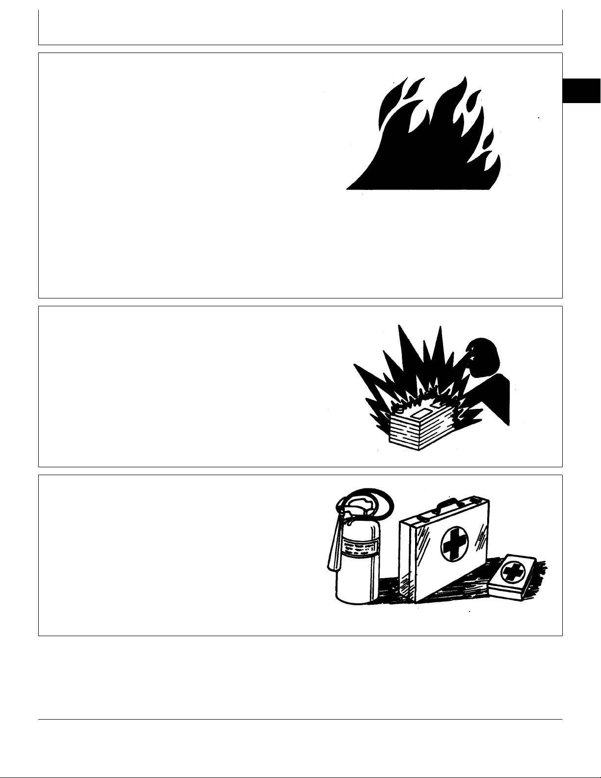
HANDLE FLUIDS SAFELY—AVOID FIRES
Group 00
Safety
When you work around fuel, do not smoke or work near
heaters or other fire hazards.
Store flammable fluids away from fire hazards. Do not
incinerate or puncture pressurized containers.
Make sure machine is clean of trash, grease, and debris.
Do not store oily rags; they can ignite and burn
spontaneously.
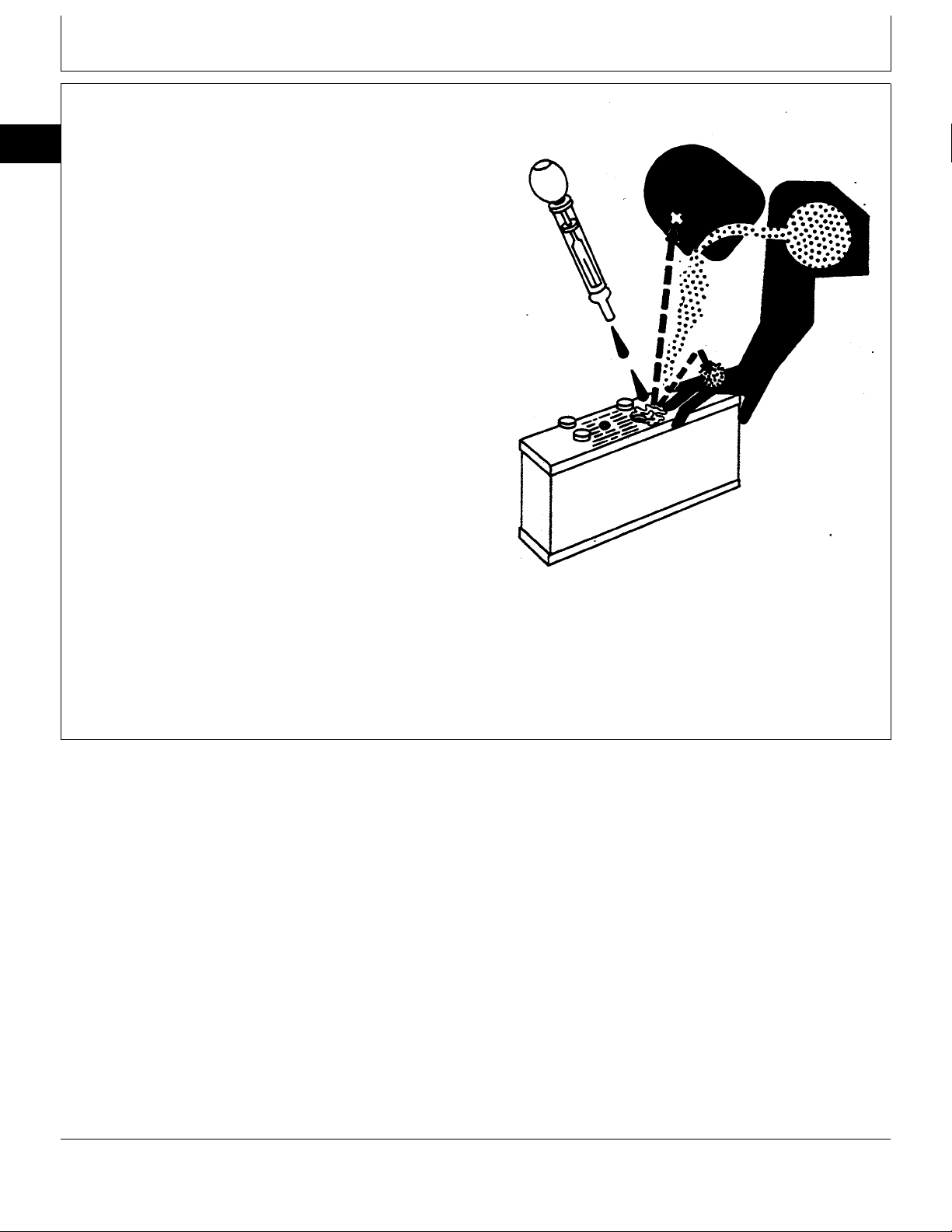
PREVENT BATTERY EXPLOSIONS
Keep sparks, lighted matches, and open flame away
from the top of battery. Battery gas can explode.
00
1
TS227 -UN-23AUG88
DX,FLAME -19-29SEP98
Never check battery charge by placing a metal object
across the posts. Use a volt-meter or hydrometer.
Do not charge a frozen battery; it may explode. Warm
battery to 16˚C (60˚F).
PREPARE FOR EMERGENCIES
Be prepared if a fire starts.
Keep a first aid kit and fire extinguisher handy.
Keep emergency numbers for doctors, ambulance
service, hospital, and fire department near your
telephone.
TS204 -UN-23AUG88
DX,SPARKS -19-03MAR93
TS291 -UN-23AUG88
DX,FIRE2 -19-03MAR93
CTM3274 (01JUL99) 00-1 Saran Liter Engines
060799
PN=10
PREVENT ACID BURNS
00
Sulfuric acid in battery electrolyte is poisonous. It is
2
strong enough to burn skin, eat holes in clothing, and
cause blindness if splashed into eyes.
Avoid the hazard by:
1. Filling batteries in a well-ventilated area.
2. Wearing eye protection and rubber gloves.
3. Avoiding breathing fumes when electrolyte is added.
4. Avoiding spilling or dripping electrolyte.
5. Use proper jump start procedure.
If you spill acid on yourself:
1. Flush your skin with water.
2. Apply baking soda or lime to help neutralize the acid.
3. Flush your eyes with water for 15—30 minutes. Get
medical attention immediately.
If acid is swallowed:
1. Do not induce vomiting.
2. Drink large amounts of water or milk, but do not
exceed 2 L (2 quarts).
3. Get medical attention immediately.
Safety
DX,POISON -19-21APR93
TS203 -UN-23AUG88
CTM3274 (01JUL99) 00-2 Saran Liter Engines
060799
PN=11
AVOID HIGH-PRESSURE FLUIDS
Safety
Escaping fluid under pressure can penetrate the skin
causing serious injury.
Avoid the hazard by relieving pressure before
disconnecting hydraulic or other lines. Tighten all
connections before applying pressure.
Search for leaks with a piece of cardboard. Protect
hands and body from high pressure fluids.
If an accident occurs, see a doctor immediately. Any
fluid injected into the skin must be surgically removed
within a few hours or gangrene may result. Doctors
unfamiliar with this type of injury should reference a
knowledgeable medical source. Such information is
available from Deere & Company Medical Department in
Moline, Illinois, U.S.A.
00
3
X9811 -UN-23AUG88
WEAR PROTECTIVE CLOTHING
Wear close fitting clothing and safety equipment
appropriate to the job.
Prolonged exposure to loud noise can cause impairment
or loss of hearing.
Wear a suitable hearing protective device such as
earmuffs or earplugs to protect against objectionable or
uncomfortable loud noises.
Operating equipment safely requires the full attention of
the operator. Do not wear radio or music headphones
while operating machine.
DX,FLUID -19-03MAR93
TS206 -UN-23AUG88
DX,WEAR -19-10SEP90
CTM3274 (01JUL99) 00-3 Saran Liter Engines
060799
PN=12
SERVICE MACHINES SAFELY
00
Tie long hair behind your head. Do not wear a necktie,
4
scarf, loose clothing, or necklace when you work near
machine tools or moving parts. If these items were to get
caught, severe injury could result.
Remove rings and other jewelry to prevent electrical
shorts and entanglement in moving parts.
WORK IN VENTILATED AREA
Engine exhaust fumes can cause sickness or death. If it
is necessary to run an engine in an enclosed area,
remove the exhaust fumes from the area with an
exhaust pipe extension.
If you do not have an exhaust pipe extension, open the
doors and get outside air into the area.
Safety
TS228 -UN-23AUG88
DX,LOOSE -19-04JUN90
WORK IN CLEAN AREA
Before starting a job:
• Clean work area and machine.
• Make sure you have all necessary tools to do your job.
• Have the right parts on hand.
• Read all instructions thoroughly; do not attempt
shortcuts.
TS220 -UN-23AUG88
DX,AIR -19-04JUN90
T6642EJ -UN-18OCT88
DX,CLEAN -19-04JUN90
CTM3274 (01JUL99) 00-4 Saran Liter Engines
060799
PN=13
Safety
REMOVE PAINT BEFORE WELDING OR
HEATING
Avoid potentially toxic fumes and dust.
Hazardous fumes can be generated when paint is
heated by welding, soldering, or using a torch.
Do all work outside or in a well ventilated area. Dispose
of paint and solvent properly.
00
5
Remove paint before welding or heating:
• If you sand or grind paint, avoid breathing the dust.
Wear an approved respirator.
• If you use solvent or paint stripper, remove stripper
with soap and water before welding. Remove solvent or
paint stripper containers and other flammable material
from area. Allow fumes to disperse at least 15 minutes
before welding or heating.
AVOID HEATING NEAR PRESSURIZED
FLUID LINES
Flammable spray can be generated by heating near
pressurized fluid lines, resulting in severe burns to
yourself and bystanders. Do not heat by welding,
soldering, or using a torch near pressurized fluid lines or
other flammable materials. Pressurized lines can be
accidentally cut when heat goes beyond the immediate
flame area.
TS220 -UN-23AUG88
DX,PAINT -19-03MAR93
DX,TORCH -19-03MAR93
ILLUMINATE WORK AREA SAFELY
Illuminate your work area adequately but safely. Use a
portable safety light for working inside or under the
machine. Make sure the bulb is enclosed by a wire
cage. The hot filament of an accidentally broken bulb
can ignite spilled fuel or oil.
DX,LIGHT -19-04JUN90
CTM3274 (01JUL99) 00-5 Saran Liter Engines
060799
PN=14
TS953 -UN-15MAY90
TS223 -UN-23AUG88
USE PROPER LIFTING EQUIPMENT
00
Lifting heavy components incorrectly can cause severe
6
injury or machine damage.
Follow recommended procedure for removal and
installation of components in the manual.
PRACTICE SAFE MAINTENANCE
Understand service procedure before doing work. Keep
area clean and dry.
Never lubricate, service, or adjust machine while it is
moving. Keep hands, feet , and clothing from
power-driven parts. Disengage all power and operate
controls to relieve pressure. Lower equipment to the
ground. Stop the engine. Remove the key. Allow
machine to cool.
Safety
TS226 -UN-23AUG88
DX,LIFT -19-04JUN90
Securely support any machine elements that must be
raised for service work.
Keep all parts in good condition and properly installed.
Fix damage immediately. Replace worn or broken parts.
Remove any buildup of grease, oil, or debris.
On self-propelled equipment, disconnect battery ground
cable (-) before making adjustments on electrical
systems or welding on machine.
On towed implements, disconnect wiring harnesses from
tractor before servicing electrical system components or
welding on machine.
TS218 -UN-23AUG88
DX,SERV -19-04FEB99
CTM3274 (01JUL99) 00-6 Saran Liter Engines
060799
PN=15
USE PROPER TOOLS
Safety
Use tools appropriate to the work. Makeshift tools and
procedures can create safety hazards.
Use power tools only to loosen threaded parts and
fasteners.
For loosening and tightening hardware, use the correct
size tools. DO NOT use U.S. measurement tools on
metric fasteners. Avoid bodily injury caused by slipping
wrenches.
Use only service parts meeting John Deere
specifications.
DISPOSE OF WASTE PROPERLY
Improperly disposing of waste can threaten the
environment and ecology. Potentially harmful waste used
with John Deere equipment include such items as oil,
fuel, coolant, brake fluid, filters, and batteries.
00
7
TS779 -UN-08NOV89
DX,REPAIR -19-04JUN90
Use leakproof containers when draining fluids. Do not
use food or beverage containers that may mislead
someone into drinking from them.
Do not pour waste onto the ground, down a drain, or
into any water source.
Air conditioning refrigerants escaping into the air can
damage the Earth’s atmosphere. Government regulations
may require a certified air conditioning service center to
recover and recycle used air conditioning refrigerants.
Inquire on the proper way to recycle or dispose of waste
from your local environmental or recycling center, or from
your John Deere dealer.
TS1133 -UN-26NOV90
DX,DRAIN -19-03MAR93
CTM3274 (01JUL99) 00-7 Saran Liter Engines
060799
PN=16
LIVE WITH SAFETY
00
Before returning machine to customer, make sure
8
machine is functioning properly, especially the safety
systems. Install all guards and shields.
Safety
TS231 -19-07OCT88
DX,LIVE -19-15APR98
CTM3274 (01JUL99) 00-8 Saran Liter Engines
060799
PN=17
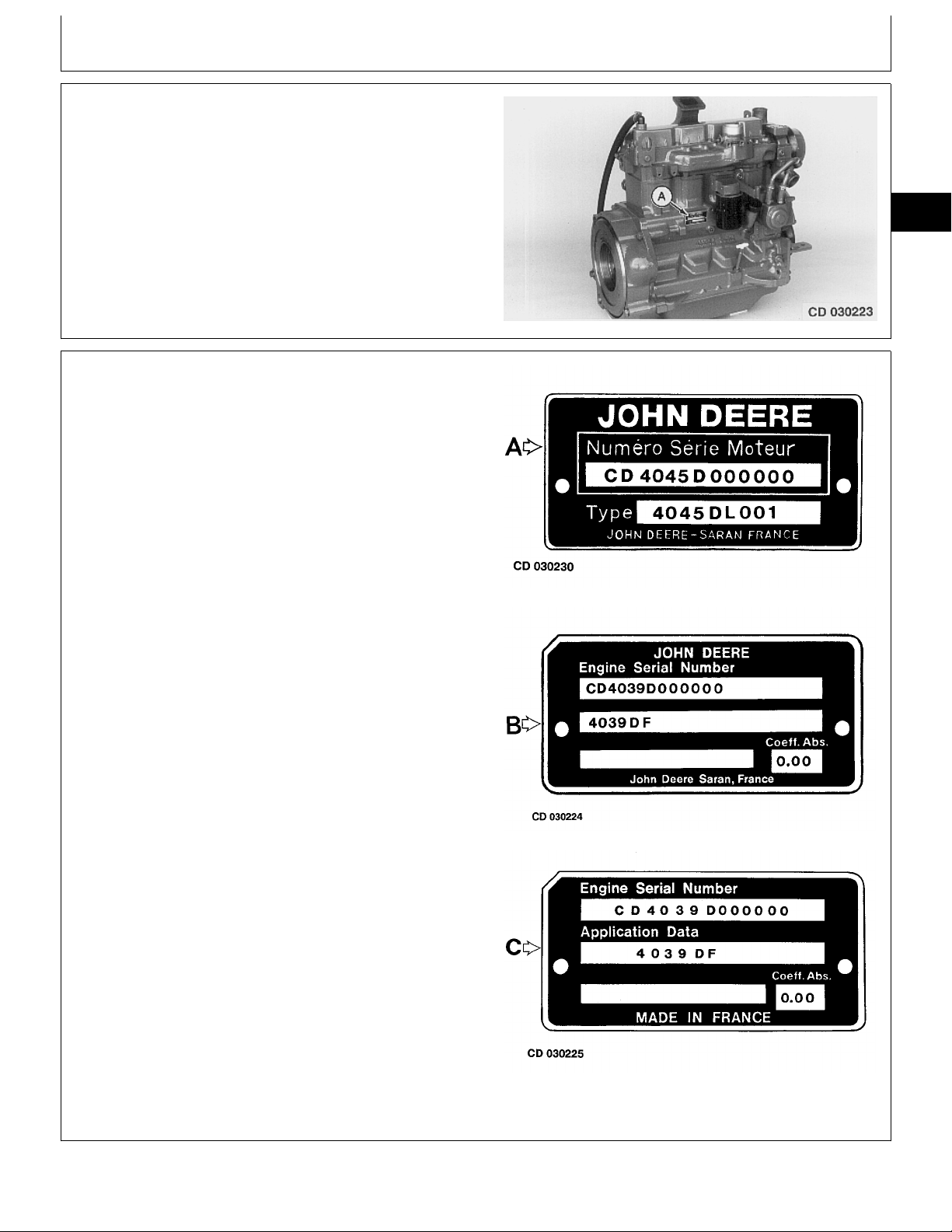
ENGINE IDENTIFICATION
The engine can be identified from the serial plate (A)
located on the right-hand side of the engine.
Some applications also have an additional serial plate
located on top of the flywheel housing. Refer to the
engine type to identify repair information in the
Component Technical Manual.
ENGINE PLATE INFORMATION (EARLIER
DESIGN)
Three types of plates are used on engines and give the
following information:
Group 01
General information
01
1
CD30223 -UN-07MAR95
CD,3274,G01,1 -19-24FEB92
First line (all plates)
CD . . . . . . . . . . . . . Manufacturing factory
(CD = Saran, T0 = Dubuque)
4045 . . . . . . . . . . Engine model designation
4 = Number of cylinders
045 = Total displacement
(045 = 4.5 liters)
D . . . . . . . . . Aspiration code
D = Naturally Aspirated
H = air-to-air aftercooled
T = Turbocharged
000000 . . . . Sequential serial number
Second line (all plates)
4045D . . . . . . . . . . . See above
L . . . . . . . . . . User code
F = OEM application
L = Mannheim
RW = Waterloo Tractor
Z = Zweibrücken
001 . . . . . . . . Application number
Third line (OEM plates only)
First field . . . . . . . . . Not used
Second field . . . . . . . Absorption coefficient of smoke
emissions (shown on certain OEM
engines)
CD30230 -UN-07MAR95CD30224 -UN-07MAR95CD30225 -UN-07MAR95
A—Plate used on John Deere equipment
B—Plate used on OEM engines
C—Generic plate used on certain OEM engines
CD,3274,G01,2 -19-04JAN99
CTM3274 (01JUL99) 01-1 Saran Liter Engines
060799
PN=18
General information/Repower engine plate
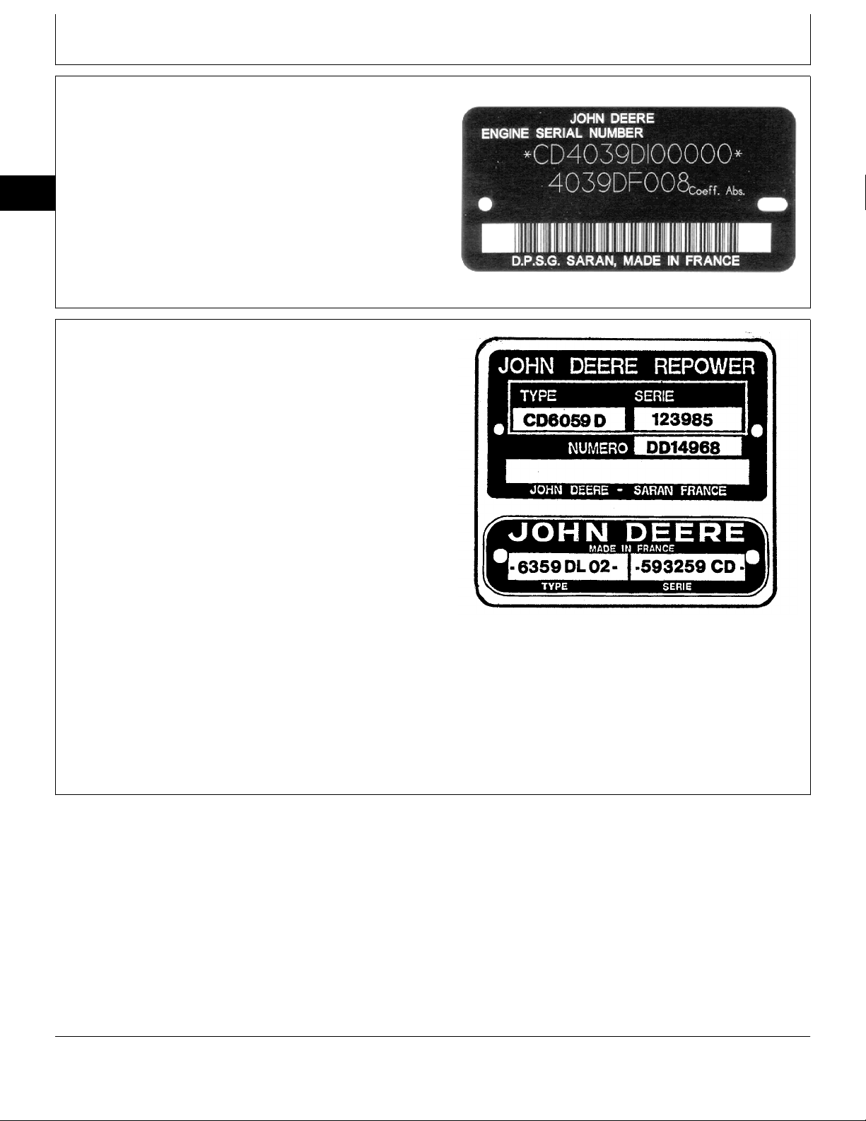
ENGINE PLATE INFORMATION (LATER
DESIGN)
A new engine plate design as shown, is now affixed to
the engine.
01
Information on this new plate is the same as previously.
2
REPOWER ENGINE PLATE
A specific plate is fixed on repower engines for proper
identification. This plate gives the following information:
First line
First field . . . . . . . . . . . Engine type
Second field . . . . . . . . . Sequential serial number
CD30705 -UN-22FEB99
CD,3274,G01,10 -19-04JAN99
Second line
DD————— . . . . . . . Repower engine part number
The third line contains a bar code information for factory
use.
NOTE: The serial number plate from original engine
must be fixed on the repower plate as shown.
CD30706 -UN-22FEB99
CD,3274,G01,6 -19-04JAN99
CTM3274 (01JUL99) 01-2 Saran Liter Engines
060799
PN=19
General information/Engine references
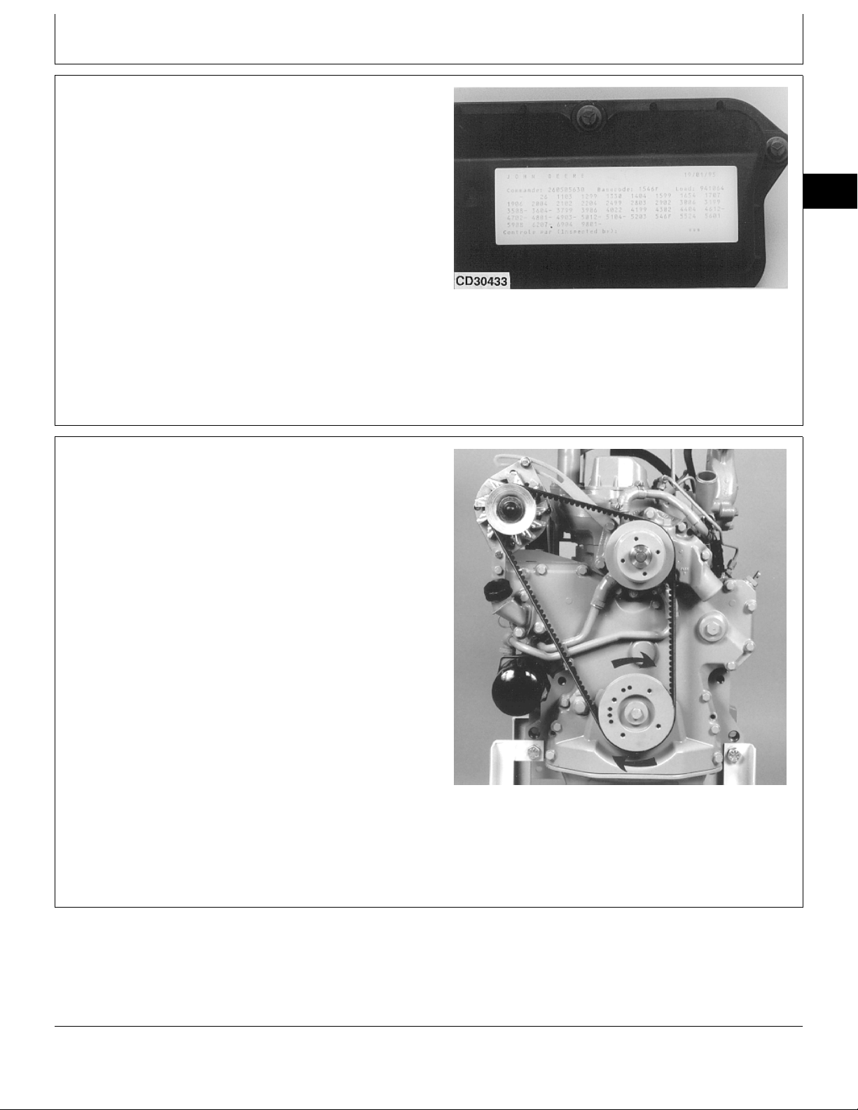
OEM ENGINE OPTION CODE LABEL
An option code label is secured to the top of the valve
cover and identifies the factory installed options on each
OEM engine to ensure correct parts acquisition.
Always provide option code information and engine base
code when ordering repair parts. A listing of option
codes is given in Parts Catalogs and Operator’s Manual.
NOTE: Before “hot tank” cleaning, ensure that option
codes are recorded elsewhere.
01
3
CD30433 -UN-10MAY95
CD,3274,G01,3 -19-01FEB94
ENGINE REFERENCES
Direction of engine rotation:
Clockwise rotation when viewed from water pump end.
Engine front reference:
The water pump end is the “front” of the engine. Cylinder
number 1 is at the front of engine.
Engine side references:
“Right-hand” and “left-hand” sides are determined by
facing the flywheel end (rear) of the engine. Right-hand
side is the camshaft side while left-hand side is the fuel
injection pump side.
CD30525 -UN-04MAY98
CD,CTM125,005 -19-01DEC97
CTM3274 (01JUL99) 01-3 Saran Liter Engines
060799
PN=20

General information/Basic engine specifications (3029 — 4039 & 6059)
BASIC ENGINE SPECIFICATIONS (3029 — 4039 & 6059)
UNIT of
01
GENERAL
Measure 3029D 3029T 4039D 4039T 6059D 6059T
4
Number of Cylinders — 3 3 4 4 6 6
Bore mm 106.5 106.5 106.5 106.5 106.5 106.5
(in.) (4.19) (4.19) (4.19) (4.19) (4.19) (4.19)
Stroke mm 110 110 110 110 110 110
(in.) (4.33) (4.33) (4.33) (4.33) (4.33) (4.33)
Displacement L 2.9 2.9 3.9 3.9 5.9 5.9
(in.3) (179) (179) (239) (239) (359) (359)
Compression Ratio — 17.8:1 17.8:1 17.8:1 17.8:1 17.8:1 17.8:1
Firing Order — 1-2-3 1-2-3 1-3-4-2 1-3-4-2 1-5-3-6-2-4 1-5-3-6-2-4
Injection System — Direct Direct Direct Direct Direct Direct
Aspiration — Natural Turbocharged Natural Turbocharged Natural Turbocharged
Rated Speed
Power
Power
Power
Weight (dry) kg 323 330 422 458 518 525
*Vary by application; refer to the machine technical or operator’s
manual for specific engine speeds and powers.
**Without fan.
*
**
@ Rated Speed (hp) (58) (79) (80) (110) (120) (165)
**
@ 1800 rpm (hp) (47) (66) (102) (165)
**
@ 1500 rpm (hp) (42) (54) (85) (140)
rpm 2500 2500 2500 2500 2500 2500
kW 43 59 60 82 89 123
kW 35 49 76 123
kW 31 40 63 104
(lbs) (712) (728) (931) (1010) (1143) (1158)
CD,3274,G01,8 -19-01FEB94
CTM3274 (01JUL99) 01-4 Saran Liter Engines
060799
PN=21

General information/Basic engine specifications (4045 & 6068)
BASIC ENGINE SPECIFICATIONS (4045 & 6068)
UNIT of
Measure 4045D 4045T 6068D 6068T 6068H
GENERAL
Number of Cylinders — 4 4 6 6 6
Bore mm 106.5 106.5 106.5 106.5 106.5
(in.) (4.19) (4.19) (4.19) (4.19) (4.19)
Stroke mm 127 127 127 127 127
(in.) (5.00) (5.00) (5.00) (5.00) (5.00)
Displacement L 4.5 4.5 6.8 6.8 6.8
(cu.in.) (276) (276) (414) (414) (414)
Compression Ratio — 17.8:1 17.2:1 17.8:1 17.2:1 17.2:1
Firing Order — 1-3-4-2 1-3-4-2 1-5-3-6-2-4 1-5-3-6-2-4 1-5-3-6-2-4
01
5
Injection System — Direct Direct Direct Direct Direct
Aspiration — Natural Turbo- Natural Turbo- Air-to-air
charged charged aftercooler
Rated Speed
**
Power
*
rpm 2400 2400 2400 2400 2200
kW 63 86 97 130 140
at Rated Speed (hp) (85) (115) (130) (175) (190)
**
Power
kW 84
at 1800 rpm (hp) (113)
**
Power
kW 70 116
at 1500 rpm (hp) (95) (155)
Weight (dry) kg 474 487 588 602
(lbs) (1046) (1074) (1297) (1328)
*Vary by application; refer to the machine technical or operator’s
manual for specific engine speeds and powers.
**Without fan.
CD,3274,G01,9 -19-04JAN99
CTM3274 (01JUL99) 01-5 Saran Liter Engines
060799
PN=22

DIESEL FUEL
General information/Fuel specifications
Consult your local fuel distributor for properties of the
diesel fuel available in your area.
In general, diesel fuels are blended to satisfy the low
01
temperature requirements of the geographical area in
6
which they are marketed.
Diesel fuels specified to EN 590 or ASTM D975 are
recommended.
In all cases, the fuel shall meet the following
properties:
• Cetane number of 40 minimum.
Cetane number greater than 50 is preferred,
especially for temperatures below -20˚C (-4˚F) or
elevations above 1500 m (5,000 ft).
• Cold Filter Plugging Point (CFPP) below the
expected low temperature OR Cloud Point at least
5˚C (9˚F) below the expected low temperature.
• Fuel lubricity should pass a minimum of 3100
gram load level as measured by the BOCLE scuffing
test.
• Sulfur content:
— Sulfur content should not exceed 0.5% Sulfur
content less than 0.05% is preferred.
— If diesel fuel with sulfur content greater than 0.5%
sulfur content is used, reduce the service interval for
engine oil and filter by 50%
— DO NOT use diesel fuel with sulfur content greater
than 1.0%
Bio-diesel fuels may be used ONLY if the fuel
properties meet DIN 51606 or equivalent specification.
DO NOT mix used engine oil or any other type of
lubricant with diesel fuel.
DX,FUEL1 -19-12FEB99
CTM3274 (01JUL99) 01-6 Saran Liter Engines
060799
PN=23
General information/Oil specifications
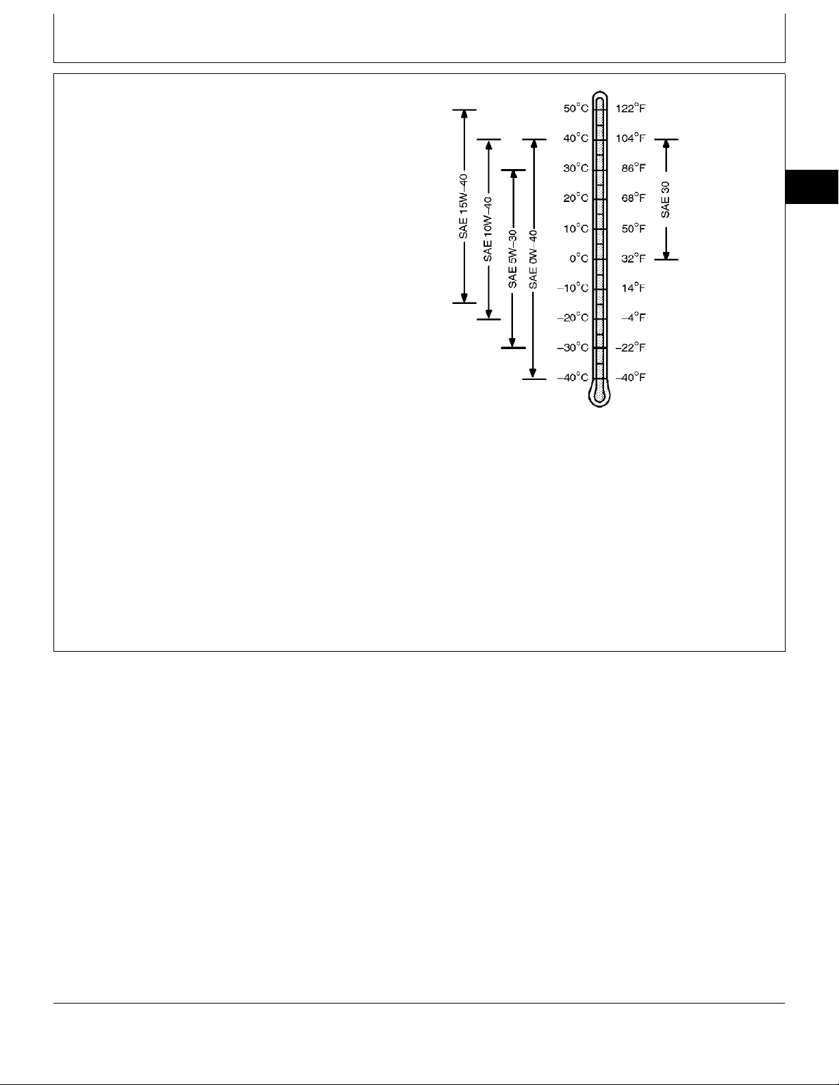
DIESEL ENGINE OIL
Use oil viscosity based on the expected air temperature
range during the period between oil changes.
The following oil is preferred.
• John Deere PLUS-50
®
The following oil is also recommended:
• John Deere TORQ-GARD SUPREME
®
Other oils may be used if they meet one or more of the
following:
• API Service Classification CG-4
• API Service Classification CF-4
• ACEA Specification E3
• ACEA Specification E2
Multi-viscosity diesel engine oils are preferred.
If diesel fuel with sulfur content greater than 0.5% is
used, reduce the service interval by 50%.
Extended service intervals may apply when John Deere
preferred engine oils are used. Consult your John Deere
dealer for more information.
01
7
TS1661 -UN-10OCT97
DX,ENOIL -19-10OCT97
CTM3274 (01JUL99) 01-7 Saran Liter Engines
060799
PN=24

DIESEL ENGINE COOLANT
General information/Coolant specifications
The engine cooling system is filled to provide
year-round protection against corrosion and cylinder
liner pitting, and winter freeze protection to -37˚C
(-34˚F).
01
8
John Deere COOL-GARD is preferred for service.
If John Deere COOL-GARD is not available, use a
low silicate ethylene glycol base coolant concentrate
in a 50% mixture of concentrate with quality water.
The coolant concentrate shall be of a quality that
provides cavitation protection to cast iron and
aluminum parts in the cooling system. John Deere
COOL-GARD meets this requirement.
A 50% mixture of ethylene glycol engine coolant in
water provides freeze protection to -37˚C (-34˚F). If
protection at lower temperatures is required, consult
your John Deere dealer for recommendations.
Water quality is important to the performance of the
cooling system. Distilled, deionized, or demineralized
water is recommended for mixing with ethylene glycol
base engine coolant concentrate.
IMPORTANT: Do not use cooling system sealing
additives or antifreeze that contains
sealing additives.
Coolant drain intervals
Drain the factory fill engine coolant, flush the cooling
system, and refill with new coolant after the first 3
years or 3000 hours of operation. Subsequent drain
intervals are determined by the coolant used for
service. At each interval, drain the coolant, flush the
cooling system, and refill with new coolant.
When John Deere COOL-GARD is used, the coolant
drain interval is 3 years or 3000 hours operation.
If COOL-GARD is not used, the drain interval is
reduced to 2 years or 2000 hours of operation.
DX,COOL8 -19-12FEB99
CTM3274 (01JUL99) 01-8 Saran Liter Engines
060799
PN=25
General information/Metric cap screw torque values
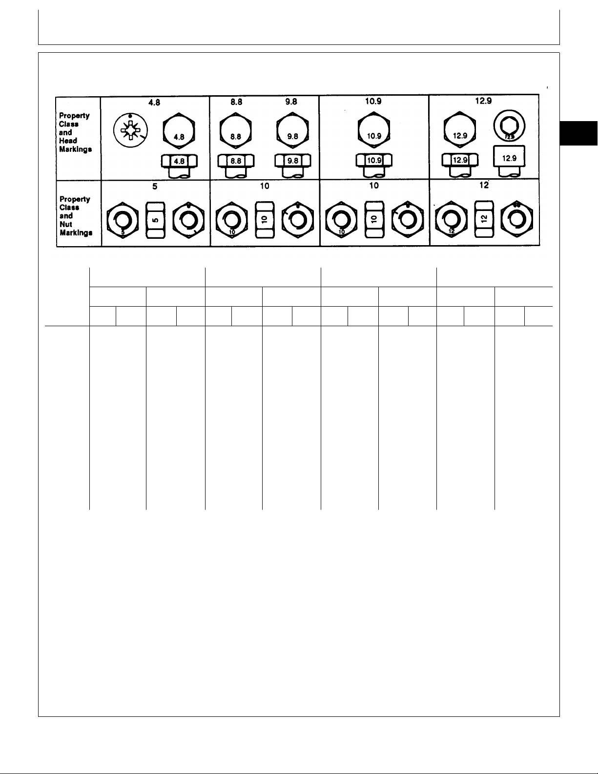
METRIC BOLT AND CAP SCREW TORQUE VALUES
Class 4.8 Class 8.8 or 9.8 Class 10.9 Class 12.9
01
9
TS1163 -19-04MAR91
Size Lubricated
N·m lb-ft N·m lb-ft N·m lb-ft N·m lb-ft N·m lb-ft N·m lb-ft N·m lb-ft N·m lb-ft
M6 4.8 3.5 6 4.5 9 6.5 11 8.5 13 9.5 17 12 15 11.5 19 14.5
M8 12 8.5 15 11 22 16 28 20 32 24 40 30 37 28 47 35
M10 23 17 29 21 43 32 55 40 63 47 80 60 75 55 95 70
M12 40 29 50 37 75 55 95 70 110 80 140 105 130 95 165 120
M14 63 47 80 60 120 88 150 110 175 130 225 165 205 150 260 190
M16 100 73 125 92 190 140 240 175 275 200 350 255 320 240 400 300
M18 135 100 175 125 260 195 330 250 375 275 475 350 440 325 560 410
M20 190 140 240 180 375 275 475 350 530 400 675 500 625 460 800 580
M22 260 190 330 250 510 375 650 475 725 540 925 675 850 625 1075 800
M24 330 250 425 310 650 475 825 600 925 675 1150 850 1075 800 1350 1000
M27 490 360 625 450 950 700 1200 875 1350 1000 1700 1250 1600 1150 2000 1500
M30 675 490 850 625 1300 950 1650 1200 1850 1350 2300 1700 2150 1600 2700 2000
M33 900 675 1150 850 1750 1300 2200 1650 2500 1850 3150 2350 2900 2150 3700 2750
M36 1150 850 1450 1075 2250 1650 2850 2100 3200 2350 4050 3000 3750 2750 4750 3500
a
DO NOT use these values if a different torque value
or tightening procedure is given for a specific
application. Torque values listed are for general use
Dry
a
Lubricated
a
Dry
a
Lubricated
a
Dry
a
Lubricated
a
Dry
a
Make sure fasteners threads are clean and that you
properly start thread engagement. This will prevent
them from failing when tightening.
only. Check tightness of fasteners periodically.
Tighten plastic insert or crimped steel-type lock nuts
Shear bolts are designed to fail under predetermined
loads. Always replace shear bolts with identical
property class.
to approximately 50 percent of the dry torque shown
in the chart, applied to the nut, not to the bolt head.
Tighten toothed or serrated-type lock nuts to the full
torque value.
Fasteners should be replaced with the same or
higher property class. If higher property class
fasteners are used, these should only be tightened to
the strength of the original.
a
“Lubricated” means coated with a lubricant such as engine oil, or
fasteners with phosphate and oil coatings. “Dry” means plain or zinc
plated without any lubrication.
DX,TORQ2 -19-20JUL94
CTM3274 (01JUL99) 01-9 Saran Liter Engines
060799
PN=26
General information/Inch cap screw torque values
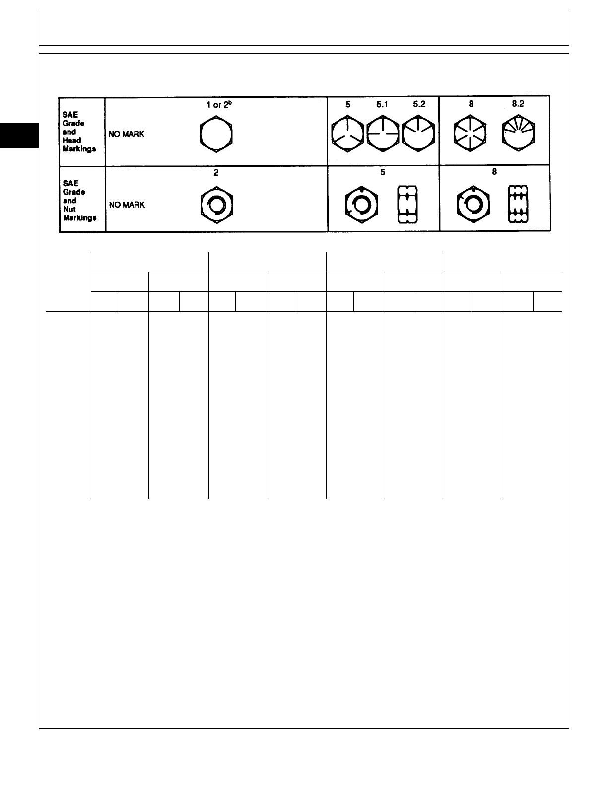
UNIFIED INCH BOLT AND CAP SCREW TORQUE VALUES
01
10
TS1162 -19-04MAR91
Grade 1 Grade 2
Size Lubricated
N·m lb-ft N·m lb-ft N·m lb-ft N·m lb-ft N·m lb-ft N·m lb-ft N·m lb-ft N·m lb-ft
1/4 3.7 2.8 4.7 3.5 6 4.5 7.5 5.5 9.5 7 12 9 13.5 10 17 12.5
5/16 7.7 5.5 10 7 12 9 15 11 20 15 25 18 28 21 35 26
3/8 14 10 17 13 22 16 27 20 35 26 44 33 50 36 63 46
7/16 22 16 28 20 35 26 44 32 55 41 70 52 80 58 100 75
1/2 33 25 42 31 53 39 67 50 85 63 110 80 120 90 150 115
9/16 48 36 60 45 75 56 95 70 125 90 155 115 175 130 225 160
5/8 67 50 85 62 105 78 135 100 170 125 215 160 240 175 300 225
3/4 120 87 150 110 190 140 240 175 300 225 375 280 425 310 550 400
7/8 190 140 240 175 190 140 240 175 490 360 625 450 700 500 875 650
1 290 210 360 270 290 210 360 270 725 540 925 675 1050 750 1300 975
1-1/8 400 300 510 375 400 300 510 375 900 675 1150 850 1450 1075 1850 1350
1-1/4 570 425 725 530 570 425 725 530 1300 950 1650 1200 2050 1500 2600 1950
1-3/8 750 550 950 700 750 550 950 700 1700 1250 2150 1550 2700 2000 3400 2550
1-1/2 1000 725 1250 925 990 725 1250 930 2250 1650 2850 2100 3600 2650 4550 3350
a
Dry
a
Lubricated
DO NOT use these values if a different torque value
or tightening procedure is given for a specific
application. Torque values listed are for general use
only. Check tightness of fasteners periodically.
b
a
Dry
a
Grade 5, 5.1, or 5.2 Grade 8 or 8.2
Lubricated
a
Dry
a
Lubricated
a
Fasteners should be replaced with the same or
higher grade. If higher grade fasteners are used,
these should only be tightened to the strength of the
original.
Dry
a
Shear bolts are designed to fail under predetermined
loads. Always replace shear bolts with identical grade.
Make sure fasteners threads are clean and that you
properly start thread engagement. This will prevent
them from failing when tightening.
Tighten plastic insert or crimped steel-type lock nuts
to approximately 50 percent of the dry torque shown
in the chart, applied to the nut, not to the bolt head.
a
“Lubricated” means coated with a lubricant such as engine oil, or
fasteners with phosphate and oil coatings. “Dry” means plain or zinc
plated without any lubrication.
b
Grade 2 applies for hex cap screws (not hex bolts) up to 152 mm
(6-in.) long. Grade 1 applies for hex cap screws over 152 mm (6-in.)
long, and for all other types of bolts and screws of any length.
Tighten toothed or serrated-type lock nuts to the full
torque value.
DX,TORQ1 -19-20JUL94
CTM3274 (01JUL99) 01-10 Saran Liter Engines
060799
PN=27
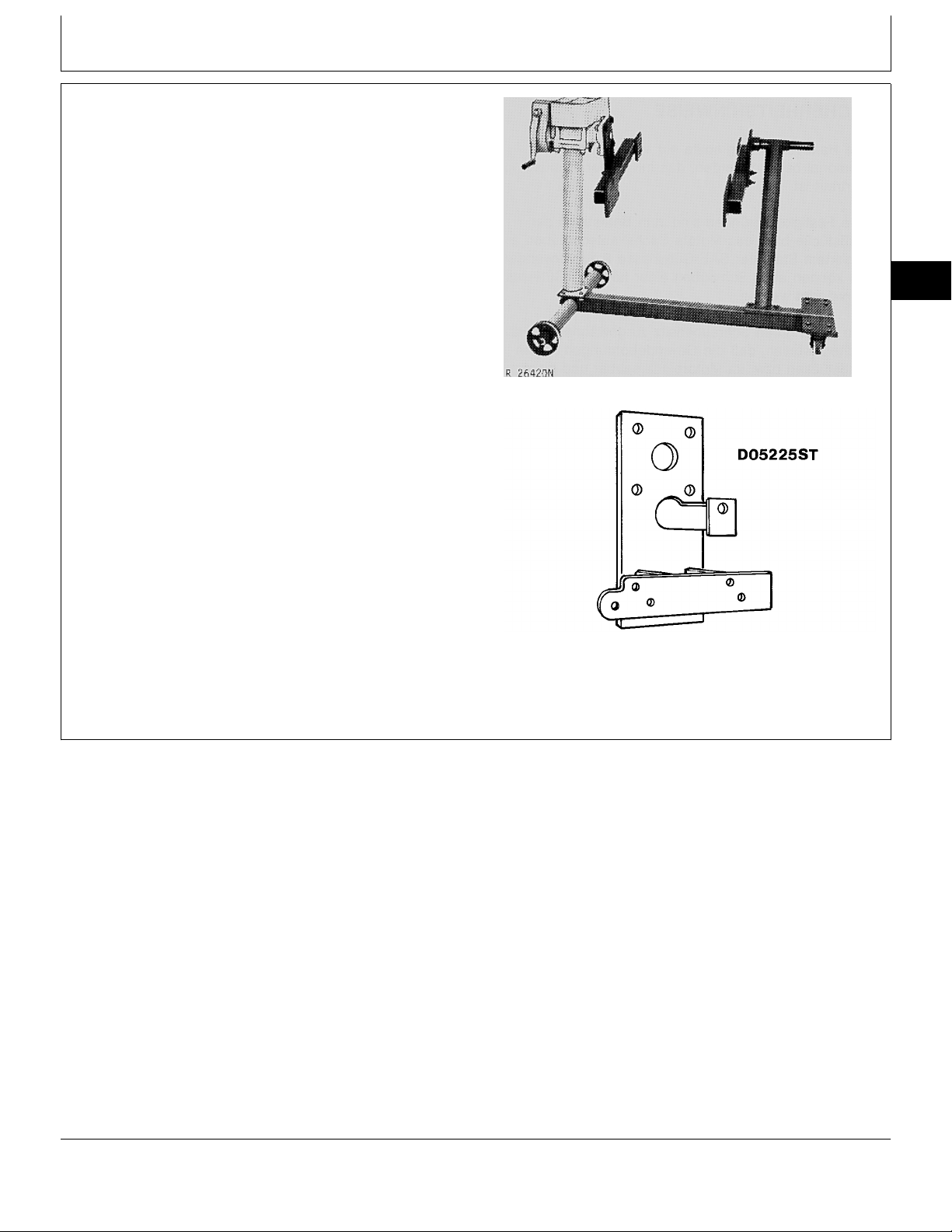
ENGINE REPAIR STAND
To facilitate engine repair, the D01003AA repair stand
can be used in conjunction with D05225ST adapter for
300 series engines.
Group 02
Engine mounting
02
1
R26420N -UN-22MAY95
D01003AA repair stand
D05225ST adapter
D05225ST -UN-22MAY95
CD,3274,G02,1 -19-24FEB92
CTM3274 (01JUL99) 02-1 Saran Liter Engines
060799
PN=28
SAFETY PRECAUTIONS
Engine mounting/Engine lifting procedure
This repair stand should be used only by qualified
service technicians familiar with this equipment.
To maintain shear strength specifications, alloy steel
SAE Grade 8 or higher cap screws must be used to
mount adapters or engine.
02
For full thread engagement, be certain that tapped
2
holes in adapters and engine blocks are clean and
not damaged. A thread length engagement equal to
1-1/2 screw diameters minimum is required to
maintain strength requirements.
To avoid structural damage or personal injury, do not
exceed the maximum weight capacity. When engine
weight is more than 450 kg (992 lb), it is
recommended to use additional support. Approximate
engine weights are listed below:
— 3 cyl. engines = 330 kg (728 lb)
— 4 cyl. engines = 450 kg (992 lb)
— 6 cyl. engines = 580 kg (1279 lb)
To prevent possible personal injury due to engine
slippage, recheck to make sure engine is solidly
mounted before releasing support from engine lifting
device.
Never permit any part of the body to be positioned
under a load being lifted or suspended. Accidental
slippage may result in personal injury.
CD,3274,G02,2 -19-24FEB92
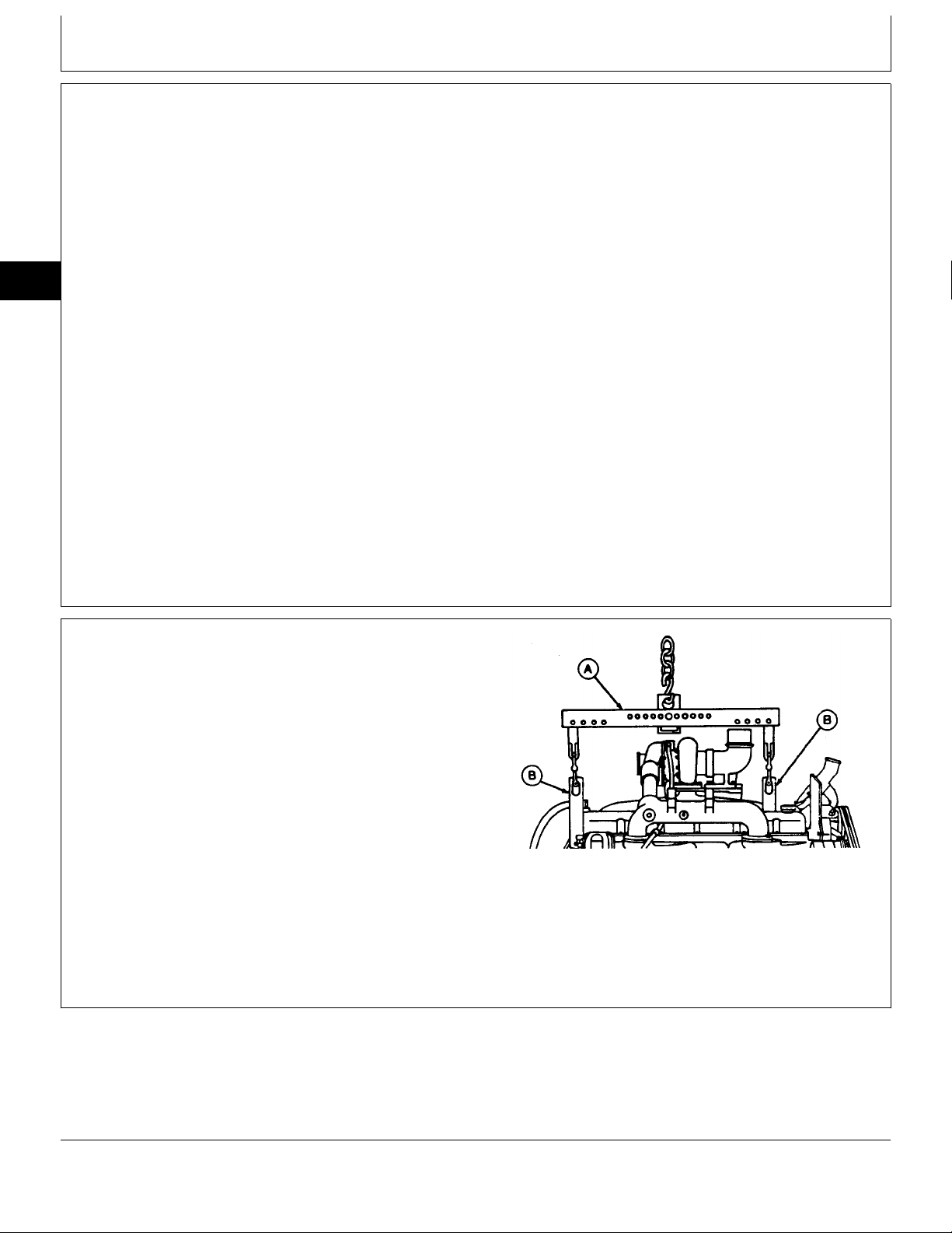
ENGINE LIFTING PROCEDURE
Attach JDG23 engine lifting sling (A), or other suitable
sling, to JD-244 engine lifting eyes (B) and hoist the
engine using a lifting device.
NOTE: Use of an engine lifting sling (as shown) is the
preferred method for lifting engines. However, if a
sling is not on hand, engine can be lifted by
chain(s) attached to lifting eyes and lifting device.
IMPORTANT: If a turbocharged engine with
low-profile design is to be lifted,
remove the turbocharger before
attaching engine to repair stand.
RG4738 -UN-18MAY90
CD,3274,G02,3 -19-01FEB94
CTM3274 (01JUL99) 02-2 Saran Liter Engines
060799
PN=29
Engine mounting/Disconnect turbocharger oil line
CLEAN ENGINE
1. Cap or plug all openings on engine. If electrical
components (starting motor, alternator, etc…) are not
removed prior to cleaning, cover with plastic and tape
securely to prevent moisture from entering.
2. Steam-clean engine thoroughly.
IMPORTANT: Never steam-clean or pour cold water
on an injection pump while it is still
warm. To do so may cause seizure of
pump parts.
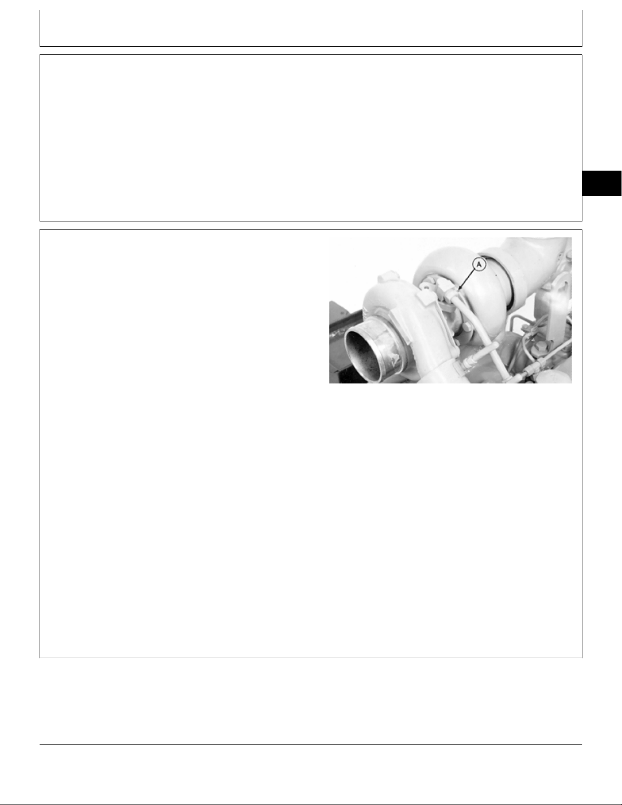
DISCONNECT TURBOCHARGER OIL INLET
LINE
Drain all engine oil and coolant, if not previously done.
IMPORTANT: When servicing turbocharged engines
on a rollover stand, disconnect turbo
oil inlet line from turbocharger (A) or
oil filter housing before rolling engine
over. Failure to do so may cause a
hydraulic lock upon starting engine.
Hydraulic lock may cause severe
engine damage.
02
3
CD,3274,G02,4 -19-24FEB92
RG5642 -UN-02APR90
Hydraulic lock occurs when trapped oil
in the oil filter housing drains through
the turbocharger, the exhaust and
intake manifolds, and then into the
cylinder head. After starting the engine,
the trapped oil in the manifold and
head is released into the cylinders
filling them with oil causing hydraulic
lock and severe engine damage.
CD,3274,G02,5 -19-24FEB92
CTM3274 (01JUL99) 02-3 Saran Liter Engines
060799
PN=30
Loading…

P
OWER
T
ECH
4.5 and 6.8 L
4045 and 6068
Tier 2 / Stage II
OEM Diesel Engines
OPERATOR’S MANUAL
P
OWER
T
ECH
4.5 and 6.8 L Tier 2 /
Stage II OEM Diesel Engines
OMRG33324 Issue 7Aug06 (ENGLISH)
CALIFORNIA
Proposition 65 Warning
Diesel engine exhaust and some of its constituents are
known to the State of California to cause cancer, birth
defects, and other reproductive harm.
If this product contains a gasoline engine:
WARNING
The engine exhaust from this product contains chemicals
known to the State of California to cause cancer, birth
defects or other reproductive harm.
The State of California requires the above two warnings.
John Deere Power Systems
LITHO IN U.S.A.
John Deere Powertech 4045 6068 4.5l 6.8l Engine Service Manual
John Deere Powertech 4045 6068 4.5l 6.8l Diesel Base Engine Ctm104 2006-2008 Service Repair Workshop Manual Download Pdf
John Deere Powertech 8.1l Diesel Engine Manual
John Deere PowerTech 6081 8.1L Diesel Engines
John Deere Powertech 6090 9.0l Diesel Engines Tier 3
John Deere Powertech 4045 6068 4.5l 6.8l Engine Service Manual
For complete service information also see:
POWERTECH Diesel Engines—Mechanical
Fuel Systems …. CTM207
POWERTECH Diesel Engines—Level 4
Electronic Fuel Systems with Bosch VP44
Pump ….CTM170
POWERTECH Diesel Engines—Level 12
Electronic Fuel Systems with Stanadyne
DE10 Pump …. CTM331
POWERTECH Diesel Engines—Level 1
Electronic Fuel Systems with Delphi/Lucas
DP201 Pump …. CTM284
POWERTECH Diesel Engines—Level 11
Electronic Fuel Systems with Denso
HPCR ….CTM220
POWERTECH Diesel Engines and
PowerTech Plus—Level 14 Electronic Fuel
Systems with Denso HPCR….CTM320
Alternators and Starter Motors….CTM77
OEM Engine Accessories … CTM67 (English Only).
Complete Component Technical Manual for John Deere PowerTech 4.5l 6.8l Diesel Engines. It’s the identical carrier guide utilized by sellers that assured to be absolutely useful and intact with none lacking web page.
This John Deere Base Engine Technical Manual – PowerTech 4.5l 6.8l Diesel Engines is split into extraordinary sections. Each segment covers a selected aspect or gadget with specific illustrations.
A desk of contents is positioned at the start of every segment. Pages are effortlessly determined via way of means of category, and every web page is expandable for remarkable detail. The printer-prepared PDF files paintings like a allure on all sorts of devices.
John Deere Base Engine Technical Manual – PowerTech 4.5l 6.8l Diesel Base Engine; (bookmarked, Searchable, Printable, excessive excellent PDF)
John Deere Powertech 4045 6068 4.5l 6.8l Engine Service Manual
EXCERPT:
TABLE OF CONTENTS
This manual is written for an experienced technician. Essential tools required in performing certain service work are identified in this manual and are recommended for use. This manual (CTM104) covers only the base engine.
It is one of seven volumes on 4.5L and 6.8L engines. The following six companion manuals cover fuel system and electronics repair, operation and diagnostics:
· CTM207—Mechanical Fuel Systems
· CTM170—Level 4 Electronic Fuel Systems with Bosch VP44 Pump
· CTM331—Level 12 Electronic Fuel Systems with Stanadyne DE10 Pump
· CTM284—Level 1 Electronic Fuel Systems with Delphi/Lucas DP201 Pump
· CTM220—Level 11 Electronic Fuel Systems with Denso High Pressure Common Rail · CTM320—Level 14 Electronic Fuel Systems with Denso High Pressure Common Rail
the machine technical manual for information on component removal and installation, and gaining access to the components. Information is organized in sections and groups for the various components requiring service instruction.
Section 05 summarizes all applicable essential tools, service equipment and tools, other materials needed to do the job, and service parts kits.
Section 06 summarizes all specifications, wear tolerances, and torque values
IndexJohn Deere Powertech 4045 6068 4.5l 6.8l Engine Service Manual
John Deere Powertech 4045 6068 4.5l 6.8l Engine Service Manual
Excavator Service Repair Manual for Volvo, Doosan, Case, Komatsu, Kobelco, Hitachi, Hyundai, New holland, Terex, Bobcat, Caterpillar, Takeuchi, Kubota, Jcb,Complete Step-By-Step Instructions, Diagrams, Illustrations, Wiring Schematics, And Specifications To Completely Repair Your Vehicle With Ease!
P
OWER
T
ECH
4.5 and 6.8 L
4045 and 6068
Tier 2 / Stage II
OEM Diesel Engines
OPERATOR’S MANUAL
P
OWER
T
ECH
4.5 and 6.8 L Tier 2 /
Stage II OEM Diesel Engines
OMRG33324 Issue 7Aug06 (ENGLISH)
CALIFORNIA
Proposition 65 Warning
Diesel engine exhaust and some of its constituents are
known to the State of California to cause cancer, birth
defects, and other reproductive harm.
If this product contains a gasoline engine:
WARNING
The engine exhaust from this product contains chemicals
known to the State of California to cause cancer, birth
defects or other reproductive harm.
The State of California requires the above two warnings.
John Deere Power Systems
LITHO IN U.S.A.