
-
Олниса
- →
-
Блог
Lenze 8400 Stateline представляет собой высококачественный частотный преобразователь, разработанный для управления электрическими двигателями в разнообразных промышленных приложениях. Это устройство выделяется своей эффективностью, надежностью и простотой эксплуатации, что делает его превосходным выбором для автоматизации производственных процессов.

Преобразователь обеспечивает точное регулирование скорости и момента, что позволяет оптимизировать работу механизмов и снизить энергозатраты. Его конструкция позволяет легко интегрироваться в существующие системы автоматизации, обеспечивая гибкость в настройках и возможность адаптации к специфическим требованиям различных производств.
Технические характеристики
Основные характеристики:
- Диапазон мощности: преобразователь доступен в различных версиях, поддерживающих мощности от 0.25 кВт до 75 кВт.
- Напряжение питания: работает в диапазоне 200-480 В.
- Интерфейсы: поддерживает различные протоколы связи, такие как EtherCAT, Profibus и CANopen.
- Защита: имеет встроенные функции защиты, включая защиту от перегрева, перегрузок и коротких замыканий.
Установка и настройка
При установке Lenze 8400 Stateline необходимо учитывать следующие рекомендации:
- Место установки: Убедитесь, что преобразователь установлен в защищенном и хорошо вентилируемом месте.
- Подключение: Следуйте инструкциям по электрическому подключению, указанным в руководстве пользователя, чтобы избежать повреждений устройства.
- Настройка параметров: Используйте встроенный дисплей или программное обеспечение Lenze для настройки параметров устройства в соответствии с требованиями вашего приложения.
- Параметры завода: По умолчанию преобразователь настроен для стандартного применения. Однако для оптимальной работы могут потребоваться изменения в параметрах.
- Программирование: Используйте встроенный интерфейс или внешнее программное обеспечение Lenze для изменения настроек.
- Параметры, которые часто требуют настройки: Частота срабатывания; уровень защиты двигателя; режимы работы (например, плавный запуск, торможение).
- Тестирование: После завершения настройки проведите тестирование устройства. Убедитесь, что двигатель запускается и останавливается без ошибок.
Принцип работы Lenze 8400 Stateline
Механизм действия прибора заключается в следующем:
- Преобразование частоты: Устройство принимает переменное напряжение (обычно 3 фазы) и преобразует его в постоянное напряжение. Затем, с помощью инвертора, постоянное напряжение преобразуется обратно в переменное с измененной частотой и амплитудой.
- Управление двигателем: Частота и напряжение управляют скоростью и моментом вращения асинхронного двигателя. Увеличение частоты приводит к увеличению скорости двигателя, в то время как уменьшение частоты снижает скорость.
- Контроль и управление: Встроенные алгоритмы управления обеспечивают оптимальное управление моментом и скоростью. Пользователь может настраивать параметры для достижения желаемых характеристик работы.
- Безопасность и диагностика: Устройство имеет встроенные функции безопасности и самодиагностики, которые помогают предотвращать повреждение оборудования и обеспечивать надежную работу.
Обслуживание
Обслуживание устройства:
- Регулярно проверяйте состояние устройства и его компонентов.
- Очистите от пыли и загрязнений.
- Периодически проверяйте соединения и контакты на наличие коррозии или повреждений.
- Следуйте всем местным стандартам и нормам безопасности при установке и обслуживании.
- Не забывайте отключать питание перед выполнением любых работ на устройстве.

Таким образом, в процессе эксплуатации преобразователь Lenze 8400 Stateline обеспечивает стабильную работу двигателей. Пользователи могут легко изменять параметры работы через интерфейс или специализированное программное обеспечение. Частотный преобразователь Lenze 8400 Stateline – это надежное решение для управления двигателями в промышленности. Его функциональность, простота в установке и настройке, а также широкий диапазон возможностей делают его востребованным инструментом для автоматизации и повышения эффективности производственных процессов.
Lenze руководства, инструкции, брошюры
Инструкции

LENZE 4800 4900 Инструкция
Размер файла: 1.72 мб
Руководство по эксплуатации LENZE 4800 4900
Скачать
Lenze 4800 4900 руководство
Размер файла: 426.50 кб
Руководство по монтажу LENZE 4800 4900
Скачать
lENZE 8200 smd ИНСТРУКЦИЯ
Размер файла: 571.64 кб
Руководство по эксплуатации LENZE 8200 smd
Скачать
LENZE smvector ИНСТРУКЦИЯ
Размер файла: 2.84 мб
Руководство пользователя Lenze smvector
Скачать
lenze 8200 vector инструкция
Размер файла: 2.41 мб
Руководство по эксплуатации Lenze 8200 vector
Скачать
Lenze 8400 инструкция
Размер файла: 4.01 мб
Руководство пользователя lenze 8400
Скачать
lenze 9300 vector инструкция
Размер файла: 657.32 кб
Руководство пользователя Lenze 9300 vector
Скачать
Lenze 9400 инструкция
Размер файла: 7.36 мб
Руководство пользователя lenze 9400 англ.
Скачать
lenze 8200 tmd инструкция
Размер файла: 539.01 кб
Руководство пользователя Lenze 8200 tmd
Скачать
Преобразователь частоты 8400 StateLine предназначен для регулирования скорости в простых системах управления перемещениями.
При этом полностью выполнены требования Директивы по экологическому проектированию и стандарта EN IEC 61800-9-2.
Области применения: поперечное погрузочно-разгрузочное оборудование, укладчики для поддонов (интралогистика), экструдеры (производство пластмасс), системы наполнения (тароупаковочная промышленность)
Достоинства
- Для приводных систем с обратной связью по скорости или без нее
- Встроенный контроль тормозной характеристики
- Функция энергосбережения VFC eco
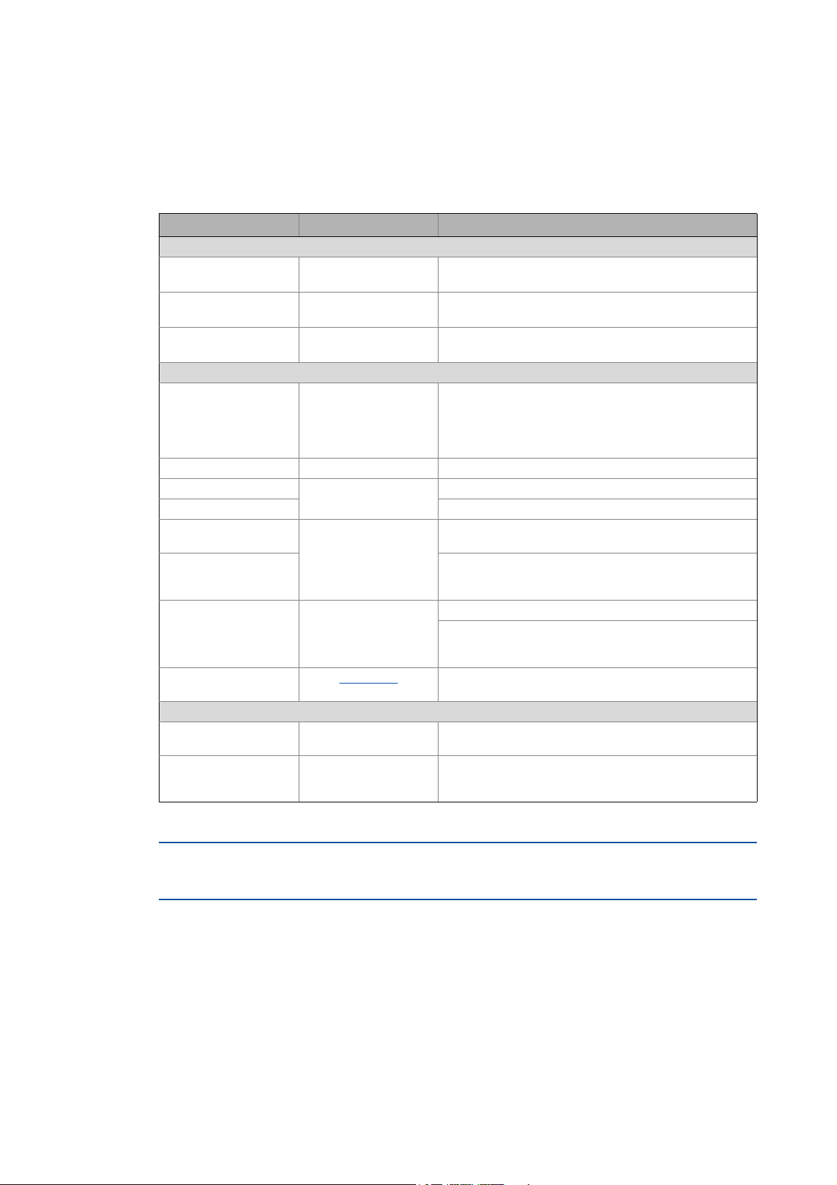
Технические данные и особенности
| Технические данные |
0.25 … 45 кВт |
|---|---|
| Возможности подключения |
1 фазы 230 В пер. тока 3 фазы 400 В пер. тока 3 фазы 480 В пер. тока 5 цифровых входов 1 цифровой выход 1 аналоговый вход 1 аналоговый выход 1 реле с замык./размык. контактом Шина пост. тока (на 400 В) мониторинг температуры двигателя |
| Связь |
CANopen EtherCAT EtherNet/IP POWERLINK PROFIBUS PROFINET |
Регламент-ЕС-об-изделиях-двойного-назначения
Поддержка продукта
+7 863 307-72-00
office@nzvo.ru
г. Ростов-на-Дону, проспект Чехова, 50
О компании
Каталог
Контакты
Библиотека
Опросный лист
Подпишитесь на рассылку
Узнайте больше о нашем бизнесе. Вы будете первым, кто узнает о наших акциях и распродажах.
Почта
Нажимая на кнопку, вы соглашаетесь на обработку персональных данных
2025 © Все права защищены
Политика конфиденциальности
Сделано в
Inverter
8400
Inverter Drives 8400 StateLine C _ _ _ _ _ _ _ _
E84AVSCxxxxx…
Reference manual EN
Ä.OT7ä
13465122
L

Overview of technical documentation for Inverter Drives 8400
_ _ _ _ _ _ _ _ _ _ _ _ _ _ _ _ _ _ _ _ _ _ _ _ _ _ _ _ _ _ _ _ _ _ _ _ _ _ _ _ _ _ _ _ _ _ _ _ _ _ _ _ _ _ _ _ _ _ _ _ _ _ _ _
Project planning, selection & ordering Legend:
8400 hardware manual Printed documentation
Catalogue Online documentation
(PDF/Engineer online help)
Mounting & wiring Abbreviations used:
MA 8400 BaseLine/StateLine/HighLine/TopLine BA Operating Instructions
MA for the communication module KHB Communication manual
MA for the extension module MA Mounting instructions
MA for the safety module SW Software/reference manual
MA for the accessories
Parameterisation
BA keypad
SW 8400 BaseLine
SW 8400 StateLine This documentation
SW 8400 HighLine
SW 8400 TopLine
KHB for the communication module
Drive commissioning
SW 8400 BaseLine/StateLine/HighLine/TopLine
chapter «Commissioning»
chapter «Diagnostics & error management»
Remote maintenance manual
Networking
KHB for the communication medium used
2 Lenze · 8400 StateLine · Reference manual · DMS 12.0 EN · 06/2014 · TD05/TD14

Contents
Contents
_ _ _ _ _ _ _ _ _ _ _ _ _ _ _ _ _ _ _ _ _ _ _ _ _ _ _ _ _ _ _ _ _ _ _ _ _ _ _ _ _ _ _ _ _ _ _ _ _ _ _ _ _ _ _ _ _ _ _ _ _ _ _ _
1 About this documentation _ _ _ _ _ _ _ _ _ _ _ _ _ _ _ _ _ _ _ _ _ _ _ _ _ _ _ _ _ _ _ _ _ _ _ _ _ _ _ 15
1.1 Document history _ _ _ _ _ _ _ _ _ _ _ _ _ _ _ _ _ _ _ _ _ _ _ _ _ _ _ _ _ _ _ _ _ _ _ _ _ _ _ _ _ _ _ _ 15
1.2 Conventions used _ _ _ _ _ _ _ _ _ _ _ _ _ _ _ _ _ _ _ _ _ _ _ _ _ _ _ _ _ _ _ _ _ _ _ _ _ _ _ _ _ _ _ _ 16
1.3 Terminology used _ _ _ _ _ _ _ _ _ _ _ _ _ _ _ _ _ _ _ _ _ _ _ _ _ _ _ _ _ _ _ _ _ _ _ _ _ _ _ _ _ _ _ _ 17
1.4 Definition of the notes used _ _ _ _ _ _ _ _ _ _ _ _ _ _ _ _ _ _ _ _ _ _ _ _ _ _ _ _ _ _ _ _ _ _ _ _ _ _ 19
2 Introduction: Parameterising the controller _ _ _ _ _ _ _ _ _ _ _ _ _ _ _ _ _ _ _ _ _ _ _ _ _ _ _ _ _ _ 20
2.1 Integrated technology applications _ _ _ _ _ _ _ _ _ _ _ _ _ _ _ _ _ _ _ _ _ _ _ _ _ _ _ _ _ _ _ _ _ _ 22
2.1.1 Purpose of the technology applications _ _ _ _ _ _ _ _ _ _ _ _ _ _ _ _ _ _ _ _ _ _ _ _ _ _ _ 23
2.1.2 Application cases for a technology application _ _ _ _ _ _ _ _ _ _ _ _ _ _ _ _ _ _ _ _ _ _ _ 23
2.1.3 Technology application = function block interconnection _ _ _ _ _ _ _ _ _ _ _ _ _ _ _ _ _ 24
2.2 Selection of the appropriate commissioning tool _ _ _ _ _ _ _ _ _ _ _ _ _ _ _ _ _ _ _ _ _ _ _ _ _ _ _ 25
2.2.1 Overview: Accessories for commissioning _ _ _ _ _ _ _ _ _ _ _ _ _ _ _ _ _ _ _ _ _ _ _ _ _ 26
2.3 General notes on parameters _ _ _ _ _ _ _ _ _ _ _ _ _ _ _ _ _ _ _ _ _ _ _ _ _ _ _ _ _ _ _ _ _ _ _ _ _ _ 27
2.3.1 Changing the parameterisation with the keypad _ _ _ _ _ _ _ _ _ _ _ _ _ _ _ _ _ _ _ _ _ 28
2.3.2 Change parameter settings with PC and Lenze software _ _ _ _ _ _ _ _ _ _ _ _ _ _ _ _ _ 31
2.3.3 Save parameter settings in the memory module safe against mains failure _ _ _ _ _ _ _ 32
2.3.4 User menu for quick access to frequently used parameters _ _ _ _ _ _ _ _ _ _ _ _ _ _ _ _ 34
2.4 Device access protection _ _ _ _ _ _ _ _ _ _ _ _ _ _ _ _ _ _ _ _ _ _ _ _ _ _ _ _ _ _ _ _ _ _ _ _ _ _ _ _ 35
2.4.1 Password protection _ _ _ _ _ _ _ _ _ _ _ _ _ _ _ _ _ _ _ _ _ _ _ _ _ _ _ _ _ _ _ _ _ _ _ _ _ 36
2.4.2 Individual password protection for single communication channels _ _ _ _ _ _ _ _ _ _ _ 38
2.4.3 Device personalisation _ _ _ _ _ _ _ _ _ _ _ _ _ _ _ _ _ _ _ _ _ _ _ _ _ _ _ _ _ _ _ _ _ _ _ _ 40
2.4.4 Unlocking the controller with a MasterPin _ _ _ _ _ _ _ _ _ _ _ _ _ _ _ _ _ _ _ _ _ _ _ _ _ 42
2.5 Device identification _ _ _ _ _ _ _ _ _ _ _ _ _ _ _ _ _ _ _ _ _ _ _ _ _ _ _ _ _ _ _ _ _ _ _ _ _ _ _ _ _ _ 43
2.5.1 Automatic acceptance of the device name in the »Engineer« _ _ _ _ _ _ _ _ _ _ _ _ _ _ _ 43
2.5.2 Extended item designation _ _ _ _ _ _ _ _ _ _ _ _ _ _ _ _ _ _ _ _ _ _ _ _ _ _ _ _ _ _ _ _ _ 43
3 Commissioning _ _ _ _ _ _ _ _ _ _ _ _ _ _ _ _ _ _ _ _ _ _ _ _ _ _ _ _ _ _ _ _ _ _ _ _ _ _ _ _ _ _ _ _ _ 44
3.1 Safety instructions with regard to commissioning _ _ _ _ _ _ _ _ _ _ _ _ _ _ _ _ _ _ _ _ _ _ _ _ _ _ 45
3.2 Notes on motor control _ _ _ _ _ _ _ _ _ _ _ _ _ _ _ _ _ _ _ _ _ _ _ _ _ _ _ _ _ _ _ _ _ _ _ _ _ _ _ _ _ 46
3.3 Preconditions for commissioning with the »Engineer« _ _ _ _ _ _ _ _ _ _ _ _ _ _ _ _ _ _ _ _ _ _ _ _ 47
3.4 Trouble-shooting during commissioning _ _ _ _ _ _ _ _ _ _ _ _ _ _ _ _ _ _ _ _ _ _ _ _ _ _ _ _ _ _ _ 48
3.5 Commissioning wizard 8400 _ _ _ _ _ _ _ _ _ _ _ _ _ _ _ _ _ _ _ _ _ _ _ _ _ _ _ _ _ _ _ _ _ _ _ _ _ _ 48
3.6 Manual motor direction of rotation check (manual control) _ _ _ _ _ _ _ _ _ _ _ _ _ _ _ _ _ _ _ _ _ 50
3.7 Commissioning of the «Actuating drive speed» technology application _ _ _ _ _ _ _ _ _ _ _ _ _ _ _ 51
3.7.1 Prepare controller for commissioning _ _ _ _ _ _ _ _ _ _ _ _ _ _ _ _ _ _ _ _ _ _ _ _ _ _ _ _ 52
3.7.2 Creating an »Engineer« project & going online _ _ _ _ _ _ _ _ _ _ _ _ _ _ _ _ _ _ _ _ _ _ _ 53
3.7.3 Parameterising the motor control _ _ _ _ _ _ _ _ _ _ _ _ _ _ _ _ _ _ _ _ _ _ _ _ _ _ _ _ _ _ 54
3.7.4 Parameterise application _ _ _ _ _ _ _ _ _ _ _ _ _ _ _ _ _ _ _ _ _ _ _ _ _ _ _ _ _ _ _ _ _ _ _ 55
3.7.5 Saving parameter settings safe against mains failure _ _ _ _ _ _ _ _ _ _ _ _ _ _ _ _ _ _ _ 57
3.7.6 Enable controller and test application _ _ _ _ _ _ _ _ _ _ _ _ _ _ _ _ _ _ _ _ _ _ _ _ _ _ _ _ 57
3.8 Commissioning of the «Switch-off positioning» technology application _ _ _ _ _ _ _ _ _ _ _ _ _ _ _ 59
3.8.1 Prepare controller for commissioning _ _ _ _ _ _ _ _ _ _ _ _ _ _ _ _ _ _ _ _ _ _ _ _ _ _ _ _ 61
3.8.2 Creating an »Engineer« project & going online _ _ _ _ _ _ _ _ _ _ _ _ _ _ _ _ _ _ _ _ _ _ _ 62
3.8.3 Parameterising the motor control _ _ _ _ _ _ _ _ _ _ _ _ _ _ _ _ _ _ _ _ _ _ _ _ _ _ _ _ _ _ 63
3.8.4 Parameterise application _ _ _ _ _ _ _ _ _ _ _ _ _ _ _ _ _ _ _ _ _ _ _ _ _ _ _ _ _ _ _ _ _ _ _ 64
3.8.5 Saving parameter settings safe against mains failure _ _ _ _ _ _ _ _ _ _ _ _ _ _ _ _ _ _ _ 66
3.8.6 Enable controller and test application _ _ _ _ _ _ _ _ _ _ _ _ _ _ _ _ _ _ _ _ _ _ _ _ _ _ _ _ 66
3.9 PC manual control _ _ _ _ _ _ _ _ _ _ _ _ _ _ _ _ _ _ _ _ _ _ _ _ _ _ _ _ _ _ _ _ _ _ _ _ _ _ _ _ _ _ _ _ 67
3.9.1 Activate PC manual control _ _ _ _ _ _ _ _ _ _ _ _ _ _ _ _ _ _ _ _ _ _ _ _ _ _ _ _ _ _ _ _ _ 67
3.9.2 Speed control _ _ _ _ _ _ _ _ _ _ _ _ _ _ _ _ _ _ _ _ _ _ _ _ _ _ _ _ _ _ _ _ _ _ _ _ _ _ _ _ _ 70
Lenze · 8400 StateLine · Reference manual · DMS 12.0 EN · 06/2014 · TD05/TD14 3

Contents
_ _ _ _ _ _ _ _ _ _ _ _ _ _ _ _ _ _ _ _ _ _ _ _ _ _ _ _ _ _ _ _ _ _ _ _ _ _ _ _ _ _ _ _ _ _ _ _ _ _ _ _ _ _ _ _ _ _ _ _ _ _ _ _
4 Device control (DCTRL) _ _ _ _ _ _ _ _ _ _ _ _ _ _ _ _ _ _ _ _ _ _ _ _ _ _ _ _ _ _ _ _ _ _ _ _ _ _ _ _ _ 72
4.1 Device commands (C00002/x) _ _ _ _ _ _ _ _ _ _ _ _ _ _ _ _ _ _ _ _ _ _ _ _ _ _ _ _ _ _ _ _ _ _ _ _ _ 74
4.1.1 Load Lenze setting _ _ _ _ _ _ _ _ _ _ _ _ _ _ _ _ _ _ _ _ _ _ _ _ _ _ _ _ _ _ _ _ _ _ _ _ _ _ 77
4.1.2 Load all parameter sets _ _ _ _ _ _ _ _ _ _ _ _ _ _ _ _ _ _ _ _ _ _ _ _ _ _ _ _ _ _ _ _ _ _ _ _ 78
4.1.3 Save all parameter sets _ _ _ _ _ _ _ _ _ _ _ _ _ _ _ _ _ _ _ _ _ _ _ _ _ _ _ _ _ _ _ _ _ _ _ _ 79
4.1.4 Enable/Inhibit controller _ _ _ _ _ _ _ _ _ _ _ _ _ _ _ _ _ _ _ _ _ _ _ _ _ _ _ _ _ _ _ _ _ _ _ 80
4.1.5 Activate/deactivate quick stop _ _ _ _ _ _ _ _ _ _ _ _ _ _ _ _ _ _ _ _ _ _ _ _ _ _ _ _ _ _ _ 81
4.1.6 Reset error _ _ _ _ _ _ _ _ _ _ _ _ _ _ _ _ _ _ _ _ _ _ _ _ _ _ _ _ _ _ _ _ _ _ _ _ _ _ _ _ _ _ 82
4.1.7 Delete logbook _ _ _ _ _ _ _ _ _ _ _ _ _ _ _ _ _ _ _ _ _ _ _ _ _ _ _ _ _ _ _ _ _ _ _ _ _ _ _ _ 82
4.1.8 Device search function _ _ _ _ _ _ _ _ _ _ _ _ _ _ _ _ _ _ _ _ _ _ _ _ _ _ _ _ _ _ _ _ _ _ _ _ 83
4.2 Device state machine and device states _ _ _ _ _ _ _ _ _ _ _ _ _ _ _ _ _ _ _ _ _ _ _ _ _ _ _ _ _ _ _ _ 84
4.2.1 FirmwareUpdate _ _ _ _ _ _ _ _ _ _ _ _ _ _ _ _ _ _ _ _ _ _ _ _ _ _ _ _ _ _ _ _ _ _ _ _ _ _ _ 85
4.2.2 Init _ _ _ _ _ _ _ _ _ _ _ _ _ _ _ _ _ _ _ _ _ _ _ _ _ _ _ _ _ _ _ _ _ _ _ _ _ _ _ _ _ _ _ _ _ _ _ 86
4.2.3 Ident _ _ _ _ _ _ _ _ _ _ _ _ _ _ _ _ _ _ _ _ _ _ _ _ _ _ _ _ _ _ _ _ _ _ _ _ _ _ _ _ _ _ _ _ _ _ 87
4.2.4 SafeTorqueOff _ _ _ _ _ _ _ _ _ _ _ _ _ _ _ _ _ _ _ _ _ _ _ _ _ _ _ _ _ _ _ _ _ _ _ _ _ _ _ _ 88
4.2.5 ReadyToSwitchOn _ _ _ _ _ _ _ _ _ _ _ _ _ _ _ _ _ _ _ _ _ _ _ _ _ _ _ _ _ _ _ _ _ _ _ _ _ _ 89
4.2.6 SwitchedOn _ _ _ _ _ _ _ _ _ _ _ _ _ _ _ _ _ _ _ _ _ _ _ _ _ _ _ _ _ _ _ _ _ _ _ _ _ _ _ _ _ _ 90
4.2.7 OperationEnabled _ _ _ _ _ _ _ _ _ _ _ _ _ _ _ _ _ _ _ _ _ _ _ _ _ _ _ _ _ _ _ _ _ _ _ _ _ _ 91
4.2.8 TroubleQSP _ _ _ _ _ _ _ _ _ _ _ _ _ _ _ _ _ _ _ _ _ _ _ _ _ _ _ _ _ _ _ _ _ _ _ _ _ _ _ _ _ _ 92
4.2.9 Trouble _ _ _ _ _ _ _ _ _ _ _ _ _ _ _ _ _ _ _ _ _ _ _ _ _ _ _ _ _ _ _ _ _ _ _ _ _ _ _ _ _ _ _ _ 93
4.2.10 Fault _ _ _ _ _ _ _ _ _ _ _ _ _ _ _ _ _ _ _ _ _ _ _ _ _ _ _ _ _ _ _ _ _ _ _ _ _ _ _ _ _ _ _ _ _ _ 94
4.2.11 SystemFault _ _ _ _ _ _ _ _ _ _ _ _ _ _ _ _ _ _ _ _ _ _ _ _ _ _ _ _ _ _ _ _ _ _ _ _ _ _ _ _ _ _ 94
4.3 Automatic restart after mains connection/fault… _ _ _ _ _ _ _ _ _ _ _ _ _ _ _ _ _ _ _ _ _ _ _ _ _ _ _ 95
4.3.1 «Inhibit at power-on» auto-start option _ _ _ _ _ _ _ _ _ _ _ _ _ _ _ _ _ _ _ _ _ _ _ _ _ _ _ 95
4.3.2 Auto-start option «Inhibit at Lenze setting» _ _ _ _ _ _ _ _ _ _ _ _ _ _ _ _ _ _ _ _ _ _ _ _ _ 97
4.4 Internal interfaces | «LS_DriveInterface» system block _ _ _ _ _ _ _ _ _ _ _ _ _ _ _ _ _ _ _ _ _ _ _ _ 98
4.4.1 wCANControl/wMCIControl control words _ _ _ _ _ _ _ _ _ _ _ _ _ _ _ _ _ _ _ _ _ _ _ _ _ 101
4.4.2 wDeviceStatusWord status word _ _ _ _ _ _ _ _ _ _ _ _ _ _ _ _ _ _ _ _ _ _ _ _ _ _ _ _ _ _ 103
5 Motor control (MCTRL) _ _ _ _ _ _ _ _ _ _ _ _ _ _ _ _ _ _ _ _ _ _ _ _ _ _ _ _ _ _ _ _ _ _ _ _ _ _ _ _ _ 104
5.1 Motor selection/Motor data _ _ _ _ _ _ _ _ _ _ _ _ _ _ _ _ _ _ _ _ _ _ _ _ _ _ _ _ _ _ _ _ _ _ _ _ _ _ 105
5.1.1 Selecting a motor from the motor catalogue in the »Engineer« _ _ _ _ _ _ _ _ _ _ _ _ _ _ 109
5.1.2 Automatic motor data identification _ _ _ _ _ _ _ _ _ _ _ _ _ _ _ _ _ _ _ _ _ _ _ _ _ _ _ _ 111
5.1.3 Application notes for asynchronous motors with high slip speed _ _ _ _ _ _ _ _ _ _ _ _ _ 117
5.2 Selecting the control mode _ _ _ _ _ _ _ _ _ _ _ _ _ _ _ _ _ _ _ _ _ _ _ _ _ _ _ _ _ _ _ _ _ _ _ _ _ _ _ 118
5.2.1 Selection help _ _ _ _ _ _ _ _ _ _ _ _ _ _ _ _ _ _ _ _ _ _ _ _ _ _ _ _ _ _ _ _ _ _ _ _ _ _ _ _ _ 122
5.3 Defining current and speed limits _ _ _ _ _ _ _ _ _ _ _ _ _ _ _ _ _ _ _ _ _ _ _ _ _ _ _ _ _ _ _ _ _ _ _ 123
5.4 V/f characteristic control (VFCplus) _ _ _ _ _ _ _ _ _ _ _ _ _ _ _ _ _ _ _ _ _ _ _ _ _ _ _ _ _ _ _ _ _ _ _ 126
5.4.1 Parameterisation dialog/signal flow _ _ _ _ _ _ _ _ _ _ _ _ _ _ _ _ _ _ _ _ _ _ _ _ _ _ _ _ 127
5.4.2 Basic settings _ _ _ _ _ _ _ _ _ _ _ _ _ _ _ _ _ _ _ _ _ _ _ _ _ _ _ _ _ _ _ _ _ _ _ _ _ _ _ _ _ 129
5.4.2.1 Defining the V/f characteristic shape _ _ _ _ _ _ _ _ _ _ _ _ _ _ _ _ _ _ _ _ _ 130
5.4.2.2 Defining current limits (Imax controller) _ _ _ _ _ _ _ _ _ _ _ _ _ _ _ _ _ _ _ 131
5.4.3 Optimising the control mode _ _ _ _ _ _ _ _ _ _ _ _ _ _ _ _ _ _ _ _ _ _ _ _ _ _ _ _ _ _ _ _ 132
5.4.3.1 Adapting the V/f base frequency _ _ _ _ _ _ _ _ _ _ _ _ _ _ _ _ _ _ _ _ _ _ _ 133
5.4.3.2 Adapting the Vmin boost _ _ _ _ _ _ _ _ _ _ _ _ _ _ _ _ _ _ _ _ _ _ _ _ _ _ _ 135
5.4.3.3 Optimising the Imax controller _ _ _ _ _ _ _ _ _ _ _ _ _ _ _ _ _ _ _ _ _ _ _ _ 136
5.4.3.4 Optimising the stalling behaviour _ _ _ _ _ _ _ _ _ _ _ _ _ _ _ _ _ _ _ _ _ _ _ 137
5.4.3.5 Torque limitation _ _ _ _ _ _ _ _ _ _ _ _ _ _ _ _ _ _ _ _ _ _ _ _ _ _ _ _ _ _ _ _ 138
5.4.3.6 Defining a user-defined V/f characteristic _ _ _ _ _ _ _ _ _ _ _ _ _ _ _ _ _ _ 140
5.4.4 Remedies for undesired drive behaviour _ _ _ _ _ _ _ _ _ _ _ _ _ _ _ _ _ _ _ _ _ _ _ _ _ _ 143
4 Lenze · 8400 StateLine · Reference manual · DMS 12.0 EN · 06/2014 · TD05/TD14

Contents
_ _ _ _ _ _ _ _ _ _ _ _ _ _ _ _ _ _ _ _ _ _ _ _ _ _ _ _ _ _ _ _ _ _ _ _ _ _ _ _ _ _ _ _ _ _ _ _ _ _ _ _ _ _ _ _ _ _ _ _ _ _ _ _
5.5 V/f characteristic control — energy-saving (VFCplusEco) _ _ _ _ _ _ _ _ _ _ _ _ _ _ _ _ _ _ _ _ _ _ _ _ 144
5.5.1 Parameterisation dialog/signal flow _ _ _ _ _ _ _ _ _ _ _ _ _ _ _ _ _ _ _ _ _ _ _ _ _ _ _ _ 145
5.5.2 Comparison of VFCplusEco — VFCplus _ _ _ _ _ _ _ _ _ _ _ _ _ _ _ _ _ _ _ _ _ _ _ _ _ _ _ _ 147
5.5.3 Basic settings _ _ _ _ _ _ _ _ _ _ _ _ _ _ _ _ _ _ _ _ _ _ _ _ _ _ _ _ _ _ _ _ _ _ _ _ _ _ _ _ _ 148
5.5.4 Optimising the control mode _ _ _ _ _ _ _ _ _ _ _ _ _ _ _ _ _ _ _ _ _ _ _ _ _ _ _ _ _ _ _ _ 149
5.5.4.1 Improving the behaviour at high dynamic load changes _ _ _ _ _ _ _ _ _ _ _ 150
5.5.4.2 Adapting the slope limitation for lowering the Eco function _ _ _ _ _ _ _ _ 151
5.5.4.3 Optimising the cos/phi controller _ _ _ _ _ _ _ _ _ _ _ _ _ _ _ _ _ _ _ _ _ _ _ 151
5.5.5 Remedies for undesired drive behaviour _ _ _ _ _ _ _ _ _ _ _ _ _ _ _ _ _ _ _ _ _ _ _ _ _ _ 152
5.6 V/f control (VFCplus + encoder) _ _ _ _ _ _ _ _ _ _ _ _ _ _ _ _ _ _ _ _ _ _ _ _ _ _ _ _ _ _ _ _ _ _ _ _ _ 154
5.6.1 Parameterisation dialog/signal flow _ _ _ _ _ _ _ _ _ _ _ _ _ _ _ _ _ _ _ _ _ _ _ _ _ _ _ _ 155
5.6.2 Basic settings _ _ _ _ _ _ _ _ _ _ _ _ _ _ _ _ _ _ _ _ _ _ _ _ _ _ _ _ _ _ _ _ _ _ _ _ _ _ _ _ _ 157
5.6.2.1 Parameterising the slip regulator _ _ _ _ _ _ _ _ _ _ _ _ _ _ _ _ _ _ _ _ _ _ _ 158
5.7 Sensorless vector control (SLVC) _ _ _ _ _ _ _ _ _ _ _ _ _ _ _ _ _ _ _ _ _ _ _ _ _ _ _ _ _ _ _ _ _ _ _ _ 161
5.7.1 Parameterisation dialog/signal flow _ _ _ _ _ _ _ _ _ _ _ _ _ _ _ _ _ _ _ _ _ _ _ _ _ _ _ _ 162
5.7.2 Types of control _ _ _ _ _ _ _ _ _ _ _ _ _ _ _ _ _ _ _ _ _ _ _ _ _ _ _ _ _ _ _ _ _ _ _ _ _ _ _ _ 164
5.7.2.1 Speed control with torque limitation _ _ _ _ _ _ _ _ _ _ _ _ _ _ _ _ _ _ _ _ _ 164
5.7.2.2 Torque control with speed limitation _ _ _ _ _ _ _ _ _ _ _ _ _ _ _ _ _ _ _ _ _ 165
5.7.3 Basic settings _ _ _ _ _ _ _ _ _ _ _ _ _ _ _ _ _ _ _ _ _ _ _ _ _ _ _ _ _ _ _ _ _ _ _ _ _ _ _ _ _ 166
5.7.4 Optimising the control mode _ _ _ _ _ _ _ _ _ _ _ _ _ _ _ _ _ _ _ _ _ _ _ _ _ _ _ _ _ _ _ _ 167
5.7.4.1 Optimising the starting performance after a controller enable _ _ _ _ _ _ _ 167
5.7.4.2 Optimise speed controller _ _ _ _ _ _ _ _ _ _ _ _ _ _ _ _ _ _ _ _ _ _ _ _ _ _ _ 168
5.7.4.3 Optimising dynamic performance and field weakening behaviour _ _ _ _ _ 169
5.7.4.4 Optimising the stalling behaviour _ _ _ _ _ _ _ _ _ _ _ _ _ _ _ _ _ _ _ _ _ _ _ 170
5.7.4.5 Optimise response to setpoint changes and determine mass inertia _ _ _ _ 171
5.7.4.6 Slip calculation from motor equivalent circuit diagram data _ _ _ _ _ _ _ _ 174
5.7.4.7 Optimising field feedforward control and torque feedforward control _ _ _ 175
5.7.5 Remedies for undesired drive behaviour _ _ _ _ _ _ _ _ _ _ _ _ _ _ _ _ _ _ _ _ _ _ _ _ _ _ 176
5.8 Sensorless control for synchronous motors (SLPSM) _ _ _ _ _ _ _ _ _ _ _ _ _ _ _ _ _ _ _ _ _ _ _ _ _ 177
5.8.1 Parameterisation dialog/signal flow _ _ _ _ _ _ _ _ _ _ _ _ _ _ _ _ _ _ _ _ _ _ _ _ _ _ _ _ 179
5.8.2 Types of control _ _ _ _ _ _ _ _ _ _ _ _ _ _ _ _ _ _ _ _ _ _ _ _ _ _ _ _ _ _ _ _ _ _ _ _ _ _ _ _ 182
5.8.3 Basic settings _ _ _ _ _ _ _ _ _ _ _ _ _ _ _ _ _ _ _ _ _ _ _ _ _ _ _ _ _ _ _ _ _ _ _ _ _ _ _ _ _ 183
5.8.4 Optimising the control mode _ _ _ _ _ _ _ _ _ _ _ _ _ _ _ _ _ _ _ _ _ _ _ _ _ _ _ _ _ _ _ _ 185
5.8.4.1 Optimise current controller _ _ _ _ _ _ _ _ _ _ _ _ _ _ _ _ _ _ _ _ _ _ _ _ _ _ 186
5.8.4.2 Optimise speed controller _ _ _ _ _ _ _ _ _ _ _ _ _ _ _ _ _ _ _ _ _ _ _ _ _ _ _ 187
5.8.4.3 Optimise response to setpoint changes and determine mass inertia _ _ _ _ 190
5.8.4.4 Current-dependent stator leakage inductance Ppp(I) _ _ _ _ _ _ _ _ _ _ _ _ 193
5.8.4.5 Setting the current setpoint filter (band-stop filter) _ _ _ _ _ _ _ _ _ _ _ _ _ 195
5.8.4.6 Adapting the max. acceleration change (jerk limitation) _ _ _ _ _ _ _ _ _ _ 196
5.8.5 Pole position identification without motion _ _ _ _ _ _ _ _ _ _ _ _ _ _ _ _ _ _ _ _ _ _ _ _ 197
5.8.6 Field weakening for synchronous motors _ _ _ _ _ _ _ _ _ _ _ _ _ _ _ _ _ _ _ _ _ _ _ _ _ _ 199
5.9 Parameterisable additional functions _ _ _ _ _ _ _ _ _ _ _ _ _ _ _ _ _ _ _ _ _ _ _ _ _ _ _ _ _ _ _ _ _ 202
5.9.1 Selection of switching frequency _ _ _ _ _ _ _ _ _ _ _ _ _ _ _ _ _ _ _ _ _ _ _ _ _ _ _ _ _ _ 202
5.9.2 Operation with increased rated power _ _ _ _ _ _ _ _ _ _ _ _ _ _ _ _ _ _ _ _ _ _ _ _ _ _ _ 206
5.9.3 Flying restart function _ _ _ _ _ _ _ _ _ _ _ _ _ _ _ _ _ _ _ _ _ _ _ _ _ _ _ _ _ _ _ _ _ _ _ _ 208
5.9.4 DC-injection braking _ _ _ _ _ _ _ _ _ _ _ _ _ _ _ _ _ _ _ _ _ _ _ _ _ _ _ _ _ _ _ _ _ _ _ _ _ 211
5.9.4.1 Manual DC-injection braking (DCB) _ _ _ _ _ _ _ _ _ _ _ _ _ _ _ _ _ _ _ _ _ _ 212
5.9.4.2 Automatic DC-injection braking (Auto-DCB) _ _ _ _ _ _ _ _ _ _ _ _ _ _ _ _ _ 212
5.9.5 Slip compensation _ _ _ _ _ _ _ _ _ _ _ _ _ _ _ _ _ _ _ _ _ _ _ _ _ _ _ _ _ _ _ _ _ _ _ _ _ _ 215
5.9.6 Oscillation damping _ _ _ _ _ _ _ _ _ _ _ _ _ _ _ _ _ _ _ _ _ _ _ _ _ _ _ _ _ _ _ _ _ _ _ _ _ 216
5.9.6.1 Oscillation damping voltage range _ _ _ _ _ _ _ _ _ _ _ _ _ _ _ _ _ _ _ _ _ _ 217
5.9.6.2 Oscillation damping in the field weakening range _ _ _ _ _ _ _ _ _ _ _ _ _ _ 218
5.9.7 Phase sequence reversal for correcting misconnected UVW motor phases _ _ _ _ _ _ _ _ 219
Lenze · 8400 StateLine · Reference manual · DMS 12.0 EN · 06/2014 · TD05/TD14 5

Contents
_ _ _ _ _ _ _ _ _ _ _ _ _ _ _ _ _ _ _ _ _ _ _ _ _ _ _ _ _ _ _ _ _ _ _ _ _ _ _ _ _ _ _ _ _ _ _ _ _ _ _ _ _ _ _ _ _ _ _ _ _ _ _ _
5.10 Encoder/feedback system _ _ _ _ _ _ _ _ _ _ _ _ _ _ _ _ _ _ _ _ _ _ _ _ _ _ _ _ _ _ _ _ _ _ _ _ _ _ _ _ 220
5.10.1 Parameterising digital inputs as encoder inputs _ _ _ _ _ _ _ _ _ _ _ _ _ _ _ _ _ _ _ _ _ _ 222
5.10.2 Generation of the actual speed value _ _ _ _ _ _ _ _ _ _ _ _ _ _ _ _ _ _ _ _ _ _ _ _ _ _ _ _ 223
5.10.3 HTL encoder at DI1/DI2 _ _ _ _ _ _ _ _ _ _ _ _ _ _ _ _ _ _ _ _ _ _ _ _ _ _ _ _ _ _ _ _ _ _ _ 224
5.11 Braking operation/brake energy management _ _ _ _ _ _ _ _ _ _ _ _ _ _ _ _ _ _ _ _ _ _ _ _ _ _ _ _ 226
5.11.1 Setting the voltage source for braking operation _ _ _ _ _ _ _ _ _ _ _ _ _ _ _ _ _ _ _ _ _ _ 229
5.11.2 Selecting the response to an increase of the DC-bus voltage _ _ _ _ _ _ _ _ _ _ _ _ _ _ _ 229
5.11.2.1 Inverter motor brake _ _ _ _ _ _ _ _ _ _ _ _ _ _ _ _ _ _ _ _ _ _ _ _ _ _ _ _ _ _ 231
5.11.3 Avoiding thermal overload of the brake resistor _ _ _ _ _ _ _ _ _ _ _ _ _ _ _ _ _ _ _ _ _ _ 234
5.11.4 Control of multiple internal brake choppers in the DC-bus system _ _ _ _ _ _ _ _ _ _ _ _ 234
5.12 Monitoring _ _ _ _ _ _ _ _ _ _ _ _ _ _ _ _ _ _ _ _ _ _ _ _ _ _ _ _ _ _ _ _ _ _ _ _ _ _ _ _ _ _ _ _ _ _ _ _ 237
5.12.1 Device overload monitoring (Ixt) _ _ _ _ _ _ _ _ _ _ _ _ _ _ _ _ _ _ _ _ _ _ _ _ _ _ _ _ _ _ 238
5.12.2 Motor overload monitoring (I2xt) _ _ _ _ _ _ _ _ _ _ _ _ _ _ _ _ _ _ _ _ _ _ _ _ _ _ _ _ _ _ 239
5.12.3 Motor overcurrent monitoring _ _ _ _ _ _ _ _ _ _ _ _ _ _ _ _ _ _ _ _ _ _ _ _ _ _ _ _ _ _ _ _ 241
5.12.4 Motor temperature monitoring (PTC) _ _ _ _ _ _ _ _ _ _ _ _ _ _ _ _ _ _ _ _ _ _ _ _ _ _ _ _ 242
5.12.5 Brake resistor monitoring (I2xt) _ _ _ _ _ _ _ _ _ _ _ _ _ _ _ _ _ _ _ _ _ _ _ _ _ _ _ _ _ _ _ 243
5.12.6 Motor phase failure monitoring _ _ _ _ _ _ _ _ _ _ _ _ _ _ _ _ _ _ _ _ _ _ _ _ _ _ _ _ _ _ _ 245
5.12.7 Motor phase error monitoring before operation _ _ _ _ _ _ _ _ _ _ _ _ _ _ _ _ _ _ _ _ _ _ 246
5.12.8 Mains phase failure monitoring _ _ _ _ _ _ _ _ _ _ _ _ _ _ _ _ _ _ _ _ _ _ _ _ _ _ _ _ _ _ _ 248
5.12.9 Maximum current monitoring _ _ _ _ _ _ _ _ _ _ _ _ _ _ _ _ _ _ _ _ _ _ _ _ _ _ _ _ _ _ _ _ 248
5.12.10 Maximum torque monitoring _ _ _ _ _ _ _ _ _ _ _ _ _ _ _ _ _ _ _ _ _ _ _ _ _ _ _ _ _ _ _ _ 249
5.12.11 Motor speed monitoring _ _ _ _ _ _ _ _ _ _ _ _ _ _ _ _ _ _ _ _ _ _ _ _ _ _ _ _ _ _ _ _ _ _ _ 249
5.12.12 Encoder open-circuit monitoring _ _ _ _ _ _ _ _ _ _ _ _ _ _ _ _ _ _ _ _ _ _ _ _ _ _ _ _ _ _ 250
5.13 Internal interfaces | System block «LS_MotorInterface» _ _ _ _ _ _ _ _ _ _ _ _ _ _ _ _ _ _ _ _ _ _ _ _ 251
5.14 Internal status signals | System block «LS_DeviceMonitor» _ _ _ _ _ _ _ _ _ _ _ _ _ _ _ _ _ _ _ _ _ _ 257
6I/O terminals _ _ _ _ _ _ _ _ _ _ _ _ _ _ _ _ _ _ _ _ _ _ _ _ _ _ _ _ _ _ _ _ _ _ _ _ _ _ _ _ _ _ _ _ _ _ _ 260
6.1 Digital terminals _ _ _ _ _ _ _ _ _ _ _ _ _ _ _ _ _ _ _ _ _ _ _ _ _ _ _ _ _ _ _ _ _ _ _ _ _ _ _ _ _ _ _ _ _ 261
6.1.1 Change function assignment _ _ _ _ _ _ _ _ _ _ _ _ _ _ _ _ _ _ _ _ _ _ _ _ _ _ _ _ _ _ _ _ 264
6.1.1.1 Using DI1 and DI2 as digital inputs _ _ _ _ _ _ _ _ _ _ _ _ _ _ _ _ _ _ _ _ _ _ 265
6.1.1.2 Using DI1 and DI2 as frequency inputs _ _ _ _ _ _ _ _ _ _ _ _ _ _ _ _ _ _ _ _ 266
6.1.1.3 Using DI1 as counting input _ _ _ _ _ _ _ _ _ _ _ _ _ _ _ _ _ _ _ _ _ _ _ _ _ _ 270
6.1.2 Internal interfaces | System block «LS_DigitalInput» _ _ _ _ _ _ _ _ _ _ _ _ _ _ _ _ _ _ _ _ 273
6.1.2.1 Output of the encoder position of the DI1/DI2 frequency input _ _ _ _ _ _ _ 275
6.1.3 Internal interfaces | System block «LS_DigitalOutput» _ _ _ _ _ _ _ _ _ _ _ _ _ _ _ _ _ _ _ 279
6.2 Analog terminals _ _ _ _ _ _ _ _ _ _ _ _ _ _ _ _ _ _ _ _ _ _ _ _ _ _ _ _ _ _ _ _ _ _ _ _ _ _ _ _ _ _ _ _ 280
6.2.1 Parameterising analog input _ _ _ _ _ _ _ _ _ _ _ _ _ _ _ _ _ _ _ _ _ _ _ _ _ _ _ _ _ _ _ _ _ 282
6.2.1.1 Signal adaptation by means of characteristic _ _ _ _ _ _ _ _ _ _ _ _ _ _ _ _ _ 284
6.2.2 Parameterising analog output _ _ _ _ _ _ _ _ _ _ _ _ _ _ _ _ _ _ _ _ _ _ _ _ _ _ _ _ _ _ _ _ 286
6.2.3 Internal interfaces | System block «LS_AnalogInput» _ _ _ _ _ _ _ _ _ _ _ _ _ _ _ _ _ _ _ _ 287
6.2.4 Internal interfaces | System block «LS_AnalogOutput» _ _ _ _ _ _ _ _ _ _ _ _ _ _ _ _ _ _ _ 287
6.3 Configuring exception handling of the output terminals _ _ _ _ _ _ _ _ _ _ _ _ _ _ _ _ _ _ _ _ _ _ _ 288
6.4 User-defined terminal assignment _ _ _ _ _ _ _ _ _ _ _ _ _ _ _ _ _ _ _ _ _ _ _ _ _ _ _ _ _ _ _ _ _ _ _ 289
6.4.1 Source-destination principle _ _ _ _ _ _ _ _ _ _ _ _ _ _ _ _ _ _ _ _ _ _ _ _ _ _ _ _ _ _ _ _ _ 290
6.4.2 Changing the terminal assignment with the keypad _ _ _ _ _ _ _ _ _ _ _ _ _ _ _ _ _ _ _ _ 291
6.4.3 Changing the terminal assignment with the »Engineer« _ _ _ _ _ _ _ _ _ _ _ _ _ _ _ _ _ 293
6 Lenze · 8400 StateLine · Reference manual · DMS 12.0 EN · 06/2014 · TD05/TD14

Contents
_ _ _ _ _ _ _ _ _ _ _ _ _ _ _ _ _ _ _ _ _ _ _ _ _ _ _ _ _ _ _ _ _ _ _ _ _ _ _ _ _ _ _ _ _ _ _ _ _ _ _ _ _ _ _ _ _ _ _ _ _ _ _ _
7 Technology applications _ _ _ _ _ _ _ _ _ _ _ _ _ _ _ _ _ _ _ _ _ _ _ _ _ _ _ _ _ _ _ _ _ _ _ _ _ _ _ _ 296
7.1 Selection of the technology application and the control mode _ _ _ _ _ _ _ _ _ _ _ _ _ _ _ _ _ _ _ _ 297
7.2 TA «Actuating drive speed» _ _ _ _ _ _ _ _ _ _ _ _ _ _ _ _ _ _ _ _ _ _ _ _ _ _ _ _ _ _ _ _ _ _ _ _ _ _ _ 298
7.2.1 Basic signal flow _ _ _ _ _ _ _ _ _ _ _ _ _ _ _ _ _ _ _ _ _ _ _ _ _ _ _ _ _ _ _ _ _ _ _ _ _ _ _ 299
7.2.2 Internal interfaces | application block «LA_NCtrl» _ _ _ _ _ _ _ _ _ _ _ _ _ _ _ _ _ _ _ _ _ 301
7.2.3 Terminal assignment of the control modes _ _ _ _ _ _ _ _ _ _ _ _ _ _ _ _ _ _ _ _ _ _ _ _ _ 309
7.2.3.1 Terminals 0 _ _ _ _ _ _ _ _ _ _ _ _ _ _ _ _ _ _ _ _ _ _ _ _ _ _ _ _ _ _ _ _ _ _ _ 310
7.2.3.2 Terminals 2 _ _ _ _ _ _ _ _ _ _ _ _ _ _ _ _ _ _ _ _ _ _ _ _ _ _ _ _ _ _ _ _ _ _ _ 311
7.2.3.3 Terminals 11 _ _ _ _ _ _ _ _ _ _ _ _ _ _ _ _ _ _ _ _ _ _ _ _ _ _ _ _ _ _ _ _ _ _ 312
7.2.3.4 Terminal 16 _ _ _ _ _ _ _ _ _ _ _ _ _ _ _ _ _ _ _ _ _ _ _ _ _ _ _ _ _ _ _ _ _ _ _ 313
7.2.3.5 Keypad _ _ _ _ _ _ _ _ _ _ _ _ _ _ _ _ _ _ _ _ _ _ _ _ _ _ _ _ _ _ _ _ _ _ _ _ _ 314
7.2.3.6 PC _ _ _ _ _ _ _ _ _ _ _ _ _ _ _ _ _ _ _ _ _ _ _ _ _ _ _ _ _ _ _ _ _ _ _ _ _ _ _ _ 315
7.2.3.7 CAN _ _ _ _ _ _ _ _ _ _ _ _ _ _ _ _ _ _ _ _ _ _ _ _ _ _ _ _ _ _ _ _ _ _ _ _ _ _ _ 316
7.2.3.8 MCI _ _ _ _ _ _ _ _ _ _ _ _ _ _ _ _ _ _ _ _ _ _ _ _ _ _ _ _ _ _ _ _ _ _ _ _ _ _ _ 317
7.2.4 Process data assignment for fieldbus communication _ _ _ _ _ _ _ _ _ _ _ _ _ _ _ _ _ _ _ 318
7.2.5 Setting parameters (short overview) _ _ _ _ _ _ _ _ _ _ _ _ _ _ _ _ _ _ _ _ _ _ _ _ _ _ _ _ 320
7.2.6 Configuration parameters _ _ _ _ _ _ _ _ _ _ _ _ _ _ _ _ _ _ _ _ _ _ _ _ _ _ _ _ _ _ _ _ _ _ 322
7.3 TA «actuating drive speed (AC Drive Profile)» _ _ _ _ _ _ _ _ _ _ _ _ _ _ _ _ _ _ _ _ _ _ _ _ _ _ _ _ _ 325
7.3.1 I/O assemblies _ _ _ _ _ _ _ _ _ _ _ _ _ _ _ _ _ _ _ _ _ _ _ _ _ _ _ _ _ _ _ _ _ _ _ _ _ _ _ _ 326
7.3.2 Basic signal flow _ _ _ _ _ _ _ _ _ _ _ _ _ _ _ _ _ _ _ _ _ _ _ _ _ _ _ _ _ _ _ _ _ _ _ _ _ _ _ 327
7.3.3 Internal interfaces | application block «LA_NCtrl» _ _ _ _ _ _ _ _ _ _ _ _ _ _ _ _ _ _ _ _ _ 330
7.3.4 Terminal assignment of the control modes _ _ _ _ _ _ _ _ _ _ _ _ _ _ _ _ _ _ _ _ _ _ _ _ _ 339
7.3.4.1 Terminals 0 _ _ _ _ _ _ _ _ _ _ _ _ _ _ _ _ _ _ _ _ _ _ _ _ _ _ _ _ _ _ _ _ _ _ _ 340
7.3.4.2 Terminals 2 _ _ _ _ _ _ _ _ _ _ _ _ _ _ _ _ _ _ _ _ _ _ _ _ _ _ _ _ _ _ _ _ _ _ _ 341
7.3.4.3 Terminals 11 _ _ _ _ _ _ _ _ _ _ _ _ _ _ _ _ _ _ _ _ _ _ _ _ _ _ _ _ _ _ _ _ _ _ 342
7.3.4.4 Terminal 16 _ _ _ _ _ _ _ _ _ _ _ _ _ _ _ _ _ _ _ _ _ _ _ _ _ _ _ _ _ _ _ _ _ _ _ 343
7.3.4.5 Keypad _ _ _ _ _ _ _ _ _ _ _ _ _ _ _ _ _ _ _ _ _ _ _ _ _ _ _ _ _ _ _ _ _ _ _ _ _ 344
7.3.4.6 PC _ _ _ _ _ _ _ _ _ _ _ _ _ _ _ _ _ _ _ _ _ _ _ _ _ _ _ _ _ _ _ _ _ _ _ _ _ _ _ _ 345
7.3.4.7 CAN _ _ _ _ _ _ _ _ _ _ _ _ _ _ _ _ _ _ _ _ _ _ _ _ _ _ _ _ _ _ _ _ _ _ _ _ _ _ _ 346
7.3.4.8 MCI _ _ _ _ _ _ _ _ _ _ _ _ _ _ _ _ _ _ _ _ _ _ _ _ _ _ _ _ _ _ _ _ _ _ _ _ _ _ _ 347
7.3.5 Process data assignment for fieldbus communication _ _ _ _ _ _ _ _ _ _ _ _ _ _ _ _ _ _ _ 348
7.3.5.1 Run/Stop event _ _ _ _ _ _ _ _ _ _ _ _ _ _ _ _ _ _ _ _ _ _ _ _ _ _ _ _ _ _ _ _ _ 349
7.3.5.2 Scaling of speed and torque values _ _ _ _ _ _ _ _ _ _ _ _ _ _ _ _ _ _ _ _ _ _ 350
7.3.6 AC Drive Profile diagnostic parameters _ _ _ _ _ _ _ _ _ _ _ _ _ _ _ _ _ _ _ _ _ _ _ _ _ _ _ 351
7.3.7 Setting parameters (short overview) _ _ _ _ _ _ _ _ _ _ _ _ _ _ _ _ _ _ _ _ _ _ _ _ _ _ _ _ 351
7.3.8 Configuration parameters _ _ _ _ _ _ _ _ _ _ _ _ _ _ _ _ _ _ _ _ _ _ _ _ _ _ _ _ _ _ _ _ _ _ 353
7.4 TA «Switch-off positioning» _ _ _ _ _ _ _ _ _ _ _ _ _ _ _ _ _ _ _ _ _ _ _ _ _ _ _ _ _ _ _ _ _ _ _ _ _ _ _ 358
7.4.1 Basic signal flow _ _ _ _ _ _ _ _ _ _ _ _ _ _ _ _ _ _ _ _ _ _ _ _ _ _ _ _ _ _ _ _ _ _ _ _ _ _ _ 360
7.4.2 Internal interfaces | application block «LA_SwitchPos» _ _ _ _ _ _ _ _ _ _ _ _ _ _ _ _ _ _ _ 361
7.4.2.1 Truth table for activating the pre-switch off _ _ _ _ _ _ _ _ _ _ _ _ _ _ _ _ _ 368
7.4.3 Terminal assignment of the control modes _ _ _ _ _ _ _ _ _ _ _ _ _ _ _ _ _ _ _ _ _ _ _ _ _ 369
7.4.3.1 Terminals 0 _ _ _ _ _ _ _ _ _ _ _ _ _ _ _ _ _ _ _ _ _ _ _ _ _ _ _ _ _ _ _ _ _ _ _ 370
7.4.3.2 Terminals 2 _ _ _ _ _ _ _ _ _ _ _ _ _ _ _ _ _ _ _ _ _ _ _ _ _ _ _ _ _ _ _ _ _ _ _ 371
7.4.3.3 Terminals 11 _ _ _ _ _ _ _ _ _ _ _ _ _ _ _ _ _ _ _ _ _ _ _ _ _ _ _ _ _ _ _ _ _ _ 372
7.4.3.4 Terminal 16 _ _ _ _ _ _ _ _ _ _ _ _ _ _ _ _ _ _ _ _ _ _ _ _ _ _ _ _ _ _ _ _ _ _ _ 373
7.4.3.5 Keypad _ _ _ _ _ _ _ _ _ _ _ _ _ _ _ _ _ _ _ _ _ _ _ _ _ _ _ _ _ _ _ _ _ _ _ _ _ 374
7.4.3.6 PC _ _ _ _ _ _ _ _ _ _ _ _ _ _ _ _ _ _ _ _ _ _ _ _ _ _ _ _ _ _ _ _ _ _ _ _ _ _ _ _ 375
7.4.3.7 CAN _ _ _ _ _ _ _ _ _ _ _ _ _ _ _ _ _ _ _ _ _ _ _ _ _ _ _ _ _ _ _ _ _ _ _ _ _ _ _ 376
7.4.3.8 MCI _ _ _ _ _ _ _ _ _ _ _ _ _ _ _ _ _ _ _ _ _ _ _ _ _ _ _ _ _ _ _ _ _ _ _ _ _ _ _ 377
7.4.4 Process data assignment for fieldbus communication _ _ _ _ _ _ _ _ _ _ _ _ _ _ _ _ _ _ _ 378
7.4.5 Setting parameters (short overview) _ _ _ _ _ _ _ _ _ _ _ _ _ _ _ _ _ _ _ _ _ _ _ _ _ _ _ _ 380
7.4.6 Configuration parameters _ _ _ _ _ _ _ _ _ _ _ _ _ _ _ _ _ _ _ _ _ _ _ _ _ _ _ _ _ _ _ _ _ _ 382
Lenze · 8400 StateLine · Reference manual · DMS 12.0 EN · 06/2014 · TD05/TD14 7

Contents
_ _ _ _ _ _ _ _ _ _ _ _ _ _ _ _ _ _ _ _ _ _ _ _ _ _ _ _ _ _ _ _ _ _ _ _ _ _ _ _ _ _ _ _ _ _ _ _ _ _ _ _ _ _ _ _ _ _ _ _ _ _ _ _
7.5 «GeneralPurpose» functions _ _ _ _ _ _ _ _ _ _ _ _ _ _ _ _ _ _ _ _ _ _ _ _ _ _ _ _ _ _ _ _ _ _ _ _ _ _ _ 385
7.5.1 Analog switch _ _ _ _ _ _ _ _ _ _ _ _ _ _ _ _ _ _ _ _ _ _ _ _ _ _ _ _ _ _ _ _ _ _ _ _ _ _ _ _ _ 385
7.5.2 Arithmetic _ _ _ _ _ _ _ _ _ _ _ _ _ _ _ _ _ _ _ _ _ _ _ _ _ _ _ _ _ _ _ _ _ _ _ _ _ _ _ _ _ _ _ 386
7.5.3 Multiplication/Division _ _ _ _ _ _ _ _ _ _ _ _ _ _ _ _ _ _ _ _ _ _ _ _ _ _ _ _ _ _ _ _ _ _ _ 386
7.5.4 Binary delay element _ _ _ _ _ _ _ _ _ _ _ _ _ _ _ _ _ _ _ _ _ _ _ _ _ _ _ _ _ _ _ _ _ _ _ _ _ 387
7.5.5 Binary logic _ _ _ _ _ _ _ _ _ _ _ _ _ _ _ _ _ _ _ _ _ _ _ _ _ _ _ _ _ _ _ _ _ _ _ _ _ _ _ _ _ _ 387
7.5.6 Analog comparison _ _ _ _ _ _ _ _ _ _ _ _ _ _ _ _ _ _ _ _ _ _ _ _ _ _ _ _ _ _ _ _ _ _ _ _ _ _ 388
7.5.7 Binary signal monitor _ _ _ _ _ _ _ _ _ _ _ _ _ _ _ _ _ _ _ _ _ _ _ _ _ _ _ _ _ _ _ _ _ _ _ _ 388
7.5.8 Analog signal monitor _ _ _ _ _ _ _ _ _ _ _ _ _ _ _ _ _ _ _ _ _ _ _ _ _ _ _ _ _ _ _ _ _ _ _ _ 389
7.5.9 D-FlipFlop _ _ _ _ _ _ _ _ _ _ _ _ _ _ _ _ _ _ _ _ _ _ _ _ _ _ _ _ _ _ _ _ _ _ _ _ _ _ _ _ _ _ _ 389
8 Basic drive functions (MCK) _ _ _ _ _ _ _ _ _ _ _ _ _ _ _ _ _ _ _ _ _ _ _ _ _ _ _ _ _ _ _ _ _ _ _ _ _ _ _ 390
8.1 Basic signal flow _ _ _ _ _ _ _ _ _ _ _ _ _ _ _ _ _ _ _ _ _ _ _ _ _ _ _ _ _ _ _ _ _ _ _ _ _ _ _ _ _ _ _ _ _ 391
8.2 Internal interfaces | System block «LS_MotionControlKernel» _ _ _ _ _ _ _ _ _ _ _ _ _ _ _ _ _ _ _ _ 392
8.2.1 MCK status word _ _ _ _ _ _ _ _ _ _ _ _ _ _ _ _ _ _ _ _ _ _ _ _ _ _ _ _ _ _ _ _ _ _ _ _ _ _ _ 397
8.2.2 MCK state machine _ _ _ _ _ _ _ _ _ _ _ _ _ _ _ _ _ _ _ _ _ _ _ _ _ _ _ _ _ _ _ _ _ _ _ _ _ _ 398
8.2.2.1 «StandBy» operating mode _ _ _ _ _ _ _ _ _ _ _ _ _ _ _ _ _ _ _ _ _ _ _ _ _ _ _ 398
8.2.3 Interface to safety system _ _ _ _ _ _ _ _ _ _ _ _ _ _ _ _ _ _ _ _ _ _ _ _ _ _ _ _ _ _ _ _ _ _ 399
8.3 Speed follower _ _ _ _ _ _ _ _ _ _ _ _ _ _ _ _ _ _ _ _ _ _ _ _ _ _ _ _ _ _ _ _ _ _ _ _ _ _ _ _ _ _ _ _ _ _ 400
8.3.1 Parameter setting _ _ _ _ _ _ _ _ _ _ _ _ _ _ _ _ _ _ _ _ _ _ _ _ _ _ _ _ _ _ _ _ _ _ _ _ _ _ 400
8.3.2 Setpoint selection _ _ _ _ _ _ _ _ _ _ _ _ _ _ _ _ _ _ _ _ _ _ _ _ _ _ _ _ _ _ _ _ _ _ _ _ _ _ 401
8.4 Holding brake control _ _ _ _ _ _ _ _ _ _ _ _ _ _ _ _ _ _ _ _ _ _ _ _ _ _ _ _ _ _ _ _ _ _ _ _ _ _ _ _ _ _ 402
8.4.1 Internal interfaces _ _ _ _ _ _ _ _ _ _ _ _ _ _ _ _ _ _ _ _ _ _ _ _ _ _ _ _ _ _ _ _ _ _ _ _ _ _ 403
8.4.2 Parameter setting _ _ _ _ _ _ _ _ _ _ _ _ _ _ _ _ _ _ _ _ _ _ _ _ _ _ _ _ _ _ _ _ _ _ _ _ _ _ 405
8.4.2.1 Operating mode _ _ _ _ _ _ _ _ _ _ _ _ _ _ _ _ _ _ _ _ _ _ _ _ _ _ _ _ _ _ _ _ 406
8.4.2.2 Functional settings _ _ _ _ _ _ _ _ _ _ _ _ _ _ _ _ _ _ _ _ _ _ _ _ _ _ _ _ _ _ _ 408
8.4.2.3 Switching thresholds _ _ _ _ _ _ _ _ _ _ _ _ _ _ _ _ _ _ _ _ _ _ _ _ _ _ _ _ _ _ 409
8.4.3 Process when brake is released _ _ _ _ _ _ _ _ _ _ _ _ _ _ _ _ _ _ _ _ _ _ _ _ _ _ _ _ _ _ _ 414
8.4.4 Process when brake is closed _ _ _ _ _ _ _ _ _ _ _ _ _ _ _ _ _ _ _ _ _ _ _ _ _ _ _ _ _ _ _ _ 415
8.4.5 Behaviour in case of pulse inhibit _ _ _ _ _ _ _ _ _ _ _ _ _ _ _ _ _ _ _ _ _ _ _ _ _ _ _ _ _ _ 417
8.4.6 Feedforward control of the motor before release _ _ _ _ _ _ _ _ _ _ _ _ _ _ _ _ _ _ _ _ _ 418
8.4.2.4 Application and release time _ _ _ _ _ _ _ _ _ _ _ _ _ _ _ _ _ _ _ _ _ _ _ _ _ 410
8.4.2.5 Ramp time for approaching the setpoint speed _ _ _ _ _ _ _ _ _ _ _ _ _ _ _ 412
8.4.2.6 Motor magnetising time (only with asynchronous motor) _ _ _ _ _ _ _ _ _ 413
8.4.2.7 Actual value monitoring _ _ _ _ _ _ _ _ _ _ _ _ _ _ _ _ _ _ _ _ _ _ _ _ _ _ _ _ 413
9 Diagnostics & error management _ _ _ _ _ _ _ _ _ _ _ _ _ _ _ _ _ _ _ _ _ _ _ _ _ _ _ _ _ _ _ _ _ _ _ 420
9.1 Basics on error handling in the controller _ _ _ _ _ _ _ _ _ _ _ _ _ _ _ _ _ _ _ _ _ _ _ _ _ _ _ _ _ _ _ 420
9.2 LED status displays _ _ _ _ _ _ _ _ _ _ _ _ _ _ _ _ _ _ _ _ _ _ _ _ _ _ _ _ _ _ _ _ _ _ _ _ _ _ _ _ _ _ _ 421
9.2.1 LED status displays of the device status _ _ _ _ _ _ _ _ _ _ _ _ _ _ _ _ _ _ _ _ _ _ _ _ _ _ _ 422
9.3 Drive diagnostics with the »Engineer« _ _ _ _ _ _ _ _ _ _ _ _ _ _ _ _ _ _ _ _ _ _ _ _ _ _ _ _ _ _ _ _ _ 423
9.3.1 Display details of the error _ _ _ _ _ _ _ _ _ _ _ _ _ _ _ _ _ _ _ _ _ _ _ _ _ _ _ _ _ _ _ _ _ _ 425
9.4 Drive diagnostics via keypad/bus system _ _ _ _ _ _ _ _ _ _ _ _ _ _ _ _ _ _ _ _ _ _ _ _ _ _ _ _ _ _ _ 426
9.5 Logbook _ _ _ _ _ _ _ _ _ _ _ _ _ _ _ _ _ _ _ _ _ _ _ _ _ _ _ _ _ _ _ _ _ _ _ _ _ _ _ _ _ _ _ _ _ _ _ _ _ 429
9.5.1 Functional description _ _ _ _ _ _ _ _ _ _ _ _ _ _ _ _ _ _ _ _ _ _ _ _ _ _ _ _ _ _ _ _ _ _ _ _ 429
9.5.2 Filtering logbook entries _ _ _ _ _ _ _ _ _ _ _ _ _ _ _ _ _ _ _ _ _ _ _ _ _ _ _ _ _ _ _ _ _ _ _ 430
9.5.3 Automatic recording of device-internal signals at the time the error occurs _ _ _ _ _ _ _ 430
9.5.4 Reading out logbook entries _ _ _ _ _ _ _ _ _ _ _ _ _ _ _ _ _ _ _ _ _ _ _ _ _ _ _ _ _ _ _ _ _ 431
9.5.5 Exporting logbook entries to a file _ _ _ _ _ _ _ _ _ _ _ _ _ _ _ _ _ _ _ _ _ _ _ _ _ _ _ _ _ _ 432
9.5.6 Storing the logbook in the project _ _ _ _ _ _ _ _ _ _ _ _ _ _ _ _ _ _ _ _ _ _ _ _ _ _ _ _ _ _ 433
9.5.7 Reading out the logbook from an external control/visualisation _ _ _ _ _ _ _ _ _ _ _ _ _ 434
9.6 Monitoring _ _ _ _ _ _ _ _ _ _ _ _ _ _ _ _ _ _ _ _ _ _ _ _ _ _ _ _ _ _ _ _ _ _ _ _ _ _ _ _ _ _ _ _ _ _ _ _ 436
9.6.1 Monitoring configuration _ _ _ _ _ _ _ _ _ _ _ _ _ _ _ _ _ _ _ _ _ _ _ _ _ _ _ _ _ _ _ _ _ _ 437
9.6.2 Setting the error response _ _ _ _ _ _ _ _ _ _ _ _ _ _ _ _ _ _ _ _ _ _ _ _ _ _ _ _ _ _ _ _ _ _ 438
9.6.3 AutoFailReset function _ _ _ _ _ _ _ _ _ _ _ _ _ _ _ _ _ _ _ _ _ _ _ _ _ _ _ _ _ _ _ _ _ _ _ _ 439
8 Lenze · 8400 StateLine · Reference manual · DMS 12.0 EN · 06/2014 · TD05/TD14

Contents
_ _ _ _ _ _ _ _ _ _ _ _ _ _ _ _ _ _ _ _ _ _ _ _ _ _ _ _ _ _ _ _ _ _ _ _ _ _ _ _ _ _ _ _ _ _ _ _ _ _ _ _ _ _ _ _ _ _ _ _ _ _ _ _
9.7 Maloperation of the drive _ _ _ _ _ _ _ _ _ _ _ _ _ _ _ _ _ _ _ _ _ _ _ _ _ _ _ _ _ _ _ _ _ _ _ _ _ _ _ _ 440
9.8 Operation without mains supply _ _ _ _ _ _ _ _ _ _ _ _ _ _ _ _ _ _ _ _ _ _ _ _ _ _ _ _ _ _ _ _ _ _ _ _ 443
9.9 Error messages of the operating system _ _ _ _ _ _ _ _ _ _ _ _ _ _ _ _ _ _ _ _ _ _ _ _ _ _ _ _ _ _ _ _ 444
9.9.1 Structure of the 32-bit error number (bit coding) _ _ _ _ _ _ _ _ _ _ _ _ _ _ _ _ _ _ _ _ _ 444
9.9.2 Structure of the 16 bit error number (bit coding) _ _ _ _ _ _ _ _ _ _ _ _ _ _ _ _ _ _ _ _ _ _ 447
9.9.3 Reset error message _ _ _ _ _ _ _ _ _ _ _ _ _ _ _ _ _ _ _ _ _ _ _ _ _ _ _ _ _ _ _ _ _ _ _ _ _ 448
9.9.4 Export error texts _ _ _ _ _ _ _ _ _ _ _ _ _ _ _ _ _ _ _ _ _ _ _ _ _ _ _ _ _ _ _ _ _ _ _ _ _ _ _ 449
9.9.5 Short overview (A-Z) _ _ _ _ _ _ _ _ _ _ _ _ _ _ _ _ _ _ _ _ _ _ _ _ _ _ _ _ _ _ _ _ _ _ _ _ _ 450
9.9.6 Cause & possible remedies _ _ _ _ _ _ _ _ _ _ _ _ _ _ _ _ _ _ _ _ _ _ _ _ _ _ _ _ _ _ _ _ _ 453
9.10 «LS_SetError_1» system block _ _ _ _ _ _ _ _ _ _ _ _ _ _ _ _ _ _ _ _ _ _ _ _ _ _ _ _ _ _ _ _ _ _ _ _ _ _ 471
10 Oscilloscope function _ _ _ _ _ _ _ _ _ _ _ _ _ _ _ _ _ _ _ _ _ _ _ _ _ _ _ _ _ _ _ _ _ _ _ _ _ _ _ _ _ _ 472
10.1 Technical data _ _ _ _ _ _ _ _ _ _ _ _ _ _ _ _ _ _ _ _ _ _ _ _ _ _ _ _ _ _ _ _ _ _ _ _ _ _ _ _ _ _ _ _ _ _ 473
10.2 User interface _ _ _ _ _ _ _ _ _ _ _ _ _ _ _ _ _ _ _ _ _ _ _ _ _ _ _ _ _ _ _ _ _ _ _ _ _ _ _ _ _ _ _ _ _ _ 474
10.3 Operation _ _ _ _ _ _ _ _ _ _ _ _ _ _ _ _ _ _ _ _ _ _ _ _ _ _ _ _ _ _ _ _ _ _ _ _ _ _ _ _ _ _ _ _ _ _ _ _ 476
10.3.1 Selecting the variables to be recorded _ _ _ _ _ _ _ _ _ _ _ _ _ _ _ _ _ _ _ _ _ _ _ _ _ _ _ _ 476
10.3.2 Selecting the recording time/sample rate _ _ _ _ _ _ _ _ _ _ _ _ _ _ _ _ _ _ _ _ _ _ _ _ _ 477
10.3.3 Defining the trigger condition _ _ _ _ _ _ _ _ _ _ _ _ _ _ _ _ _ _ _ _ _ _ _ _ _ _ _ _ _ _ _ _ 478
10.3.4 Starting recording _ _ _ _ _ _ _ _ _ _ _ _ _ _ _ _ _ _ _ _ _ _ _ _ _ _ _ _ _ _ _ _ _ _ _ _ _ _ 479
10.3.5 Adjusting the representation _ _ _ _ _ _ _ _ _ _ _ _ _ _ _ _ _ _ _ _ _ _ _ _ _ _ _ _ _ _ _ _ 479
10.3.6 Cursor function: Reading individual measured values _ _ _ _ _ _ _ _ _ _ _ _ _ _ _ _ _ _ _ 482
10.4 Managing oscillograms (measured data sets) _ _ _ _ _ _ _ _ _ _ _ _ _ _ _ _ _ _ _ _ _ _ _ _ _ _ _ _ _ 483
10.4.1 Commenting the oscillogram _ _ _ _ _ _ _ _ _ _ _ _ _ _ _ _ _ _ _ _ _ _ _ _ _ _ _ _ _ _ _ _ 483
10.4.2 Saving the oscillogram _ _ _ _ _ _ _ _ _ _ _ _ _ _ _ _ _ _ _ _ _ _ _ _ _ _ _ _ _ _ _ _ _ _ _ _ 484
10.4.3 Loading the oscillogram _ _ _ _ _ _ _ _ _ _ _ _ _ _ _ _ _ _ _ _ _ _ _ _ _ _ _ _ _ _ _ _ _ _ _ 485
10.4.4 Closing the oscillogram _ _ _ _ _ _ _ _ _ _ _ _ _ _ _ _ _ _ _ _ _ _ _ _ _ _ _ _ _ _ _ _ _ _ _ 486
10.4.5 Overlay function _ _ _ _ _ _ _ _ _ _ _ _ _ _ _ _ _ _ _ _ _ _ _ _ _ _ _ _ _ _ _ _ _ _ _ _ _ _ _ 486
10.4.6 Deleting a data set saved in the project _ _ _ _ _ _ _ _ _ _ _ _ _ _ _ _ _ _ _ _ _ _ _ _ _ _ _ 487
11 System bus «CAN on board» _ _ _ _ _ _ _ _ _ _ _ _ _ _ _ _ _ _ _ _ _ _ _ _ _ _ _ _ _ _ _ _ _ _ _ _ _ _ _ 488
11.1 General information _ _ _ _ _ _ _ _ _ _ _ _ _ _ _ _ _ _ _ _ _ _ _ _ _ _ _ _ _ _ _ _ _ _ _ _ _ _ _ _ _ _ _ 489
11.1.1 General data and application conditions _ _ _ _ _ _ _ _ _ _ _ _ _ _ _ _ _ _ _ _ _ _ _ _ _ _ 489
11.1.2 Supported protocols _ _ _ _ _ _ _ _ _ _ _ _ _ _ _ _ _ _ _ _ _ _ _ _ _ _ _ _ _ _ _ _ _ _ _ _ _ 490
11.1.3 Communication time _ _ _ _ _ _ _ _ _ _ _ _ _ _ _ _ _ _ _ _ _ _ _ _ _ _ _ _ _ _ _ _ _ _ _ _ _ 491
11.2 Possible settings via DIP switch _ _ _ _ _ _ _ _ _ _ _ _ _ _ _ _ _ _ _ _ _ _ _ _ _ _ _ _ _ _ _ _ _ _ _ _ _ 492
11.2.1 Activating the bus terminating resistor _ _ _ _ _ _ _ _ _ _ _ _ _ _ _ _ _ _ _ _ _ _ _ _ _ _ _ 492
11.2.2 Setting the baud rate _ _ _ _ _ _ _ _ _ _ _ _ _ _ _ _ _ _ _ _ _ _ _ _ _ _ _ _ _ _ _ _ _ _ _ _ _ 493
11.2.3 Setting the node address _ _ _ _ _ _ _ _ _ _ _ _ _ _ _ _ _ _ _ _ _ _ _ _ _ _ _ _ _ _ _ _ _ _ _ 493
11.3 LED status displays for the system bus _ _ _ _ _ _ _ _ _ _ _ _ _ _ _ _ _ _ _ _ _ _ _ _ _ _ _ _ _ _ _ _ _ 494
11.4 Going online via the system bus _ _ _ _ _ _ _ _ _ _ _ _ _ _ _ _ _ _ _ _ _ _ _ _ _ _ _ _ _ _ _ _ _ _ _ _ 495
11.5 Reinitialising the CANopen interface _ _ _ _ _ _ _ _ _ _ _ _ _ _ _ _ _ _ _ _ _ _ _ _ _ _ _ _ _ _ _ _ _ _ 495
11.6 Structure of the CAN data telegram _ _ _ _ _ _ _ _ _ _ _ _ _ _ _ _ _ _ _ _ _ _ _ _ _ _ _ _ _ _ _ _ _ _ 496
11.6.1 Identifier _ _ _ _ _ _ _ _ _ _ _ _ _ _ _ _ _ _ _ _ _ _ _ _ _ _ _ _ _ _ _ _ _ _ _ _ _ _ _ _ _ _ _ 496
11.6.2 User data _ _ _ _ _ _ _ _ _ _ _ _ _ _ _ _ _ _ _ _ _ _ _ _ _ _ _ _ _ _ _ _ _ _ _ _ _ _ _ _ _ _ _ 498
11.7 Communication phases/network management _ _ _ _ _ _ _ _ _ _ _ _ _ _ _ _ _ _ _ _ _ _ _ _ _ _ _ _ 499
11.7.1 Status transitions _ _ _ _ _ _ _ _ _ _ _ _ _ _ _ _ _ _ _ _ _ _ _ _ _ _ _ _ _ _ _ _ _ _ _ _ _ _ _ 500
11.7.2 Network management telegram (NMT) _ _ _ _ _ _ _ _ _ _ _ _ _ _ _ _ _ _ _ _ _ _ _ _ _ _ _ 501
11.7.3 Parameterising the controller as CAN master _ _ _ _ _ _ _ _ _ _ _ _ _ _ _ _ _ _ _ _ _ _ _ _ 502
Lenze · 8400 StateLine · Reference manual · DMS 12.0 EN · 06/2014 · TD05/TD14 9

Contents
_ _ _ _ _ _ _ _ _ _ _ _ _ _ _ _ _ _ _ _ _ _ _ _ _ _ _ _ _ _ _ _ _ _ _ _ _ _ _ _ _ _ _ _ _ _ _ _ _ _ _ _ _ _ _ _ _ _ _ _ _ _ _ _
11.8 Process data transfer _ _ _ _ _ _ _ _ _ _ _ _ _ _ _ _ _ _ _ _ _ _ _ _ _ _ _ _ _ _ _ _ _ _ _ _ _ _ _ _ _ _ 503
11.8.1 Available process data objects _ _ _ _ _ _ _ _ _ _ _ _ _ _ _ _ _ _ _ _ _ _ _ _ _ _ _ _ _ _ _ _ 504
11.8.1.1 RPDO1 | Port block «LP_CanIn1» _ _ _ _ _ _ _ _ _ _ _ _ _ _ _ _ _ _ _ _ _ _ _ _ 505
11.8.1.2 RPDO2 | «LP_CanIn2» port block _ _ _ _ _ _ _ _ _ _ _ _ _ _ _ _ _ _ _ _ _ _ _ _ 507
11.8.1.3 RPDO3 | «LP_CanIn3» port block _ _ _ _ _ _ _ _ _ _ _ _ _ _ _ _ _ _ _ _ _ _ _ _ 509
11.8.1.4 RPDO4 | «LP_CanIn4» port block _ _ _ _ _ _ _ _ _ _ _ _ _ _ _ _ _ _ _ _ _ _ _ _ 511
11.8.1.5 TPDO1 | «LP_CanOut1» port block _ _ _ _ _ _ _ _ _ _ _ _ _ _ _ _ _ _ _ _ _ _ _ 513
11.8.1.6 TPDO2 | «LP_CanOut2» port block _ _ _ _ _ _ _ _ _ _ _ _ _ _ _ _ _ _ _ _ _ _ _ 514
11.8.1.7 TPDO3 | «LP_CanOut3» port block _ _ _ _ _ _ _ _ _ _ _ _ _ _ _ _ _ _ _ _ _ _ _ 515
11.8.1.8 TPDO4 | «LP_CanOut4» port block _ _ _ _ _ _ _ _ _ _ _ _ _ _ _ _ _ _ _ _ _ _ _ 516
11.8.2 Identifiers of the process data objects _ _ _ _ _ _ _ _ _ _ _ _ _ _ _ _ _ _ _ _ _ _ _ _ _ _ _ _ 517
11.8.3 Transmission type _ _ _ _ _ _ _ _ _ _ _ _ _ _ _ _ _ _ _ _ _ _ _ _ _ _ _ _ _ _ _ _ _ _ _ _ _ _ 519
11.8.4 PDO synchronisation via sync telegram _ _ _ _ _ _ _ _ _ _ _ _ _ _ _ _ _ _ _ _ _ _ _ _ _ _ _ 521
11.8.5 Monitoring of the RPDOs for data reception _ _ _ _ _ _ _ _ _ _ _ _ _ _ _ _ _ _ _ _ _ _ _ _ 522
11.8.6 Configuring exception handling of the CAN PDOs _ _ _ _ _ _ _ _ _ _ _ _ _ _ _ _ _ _ _ _ _ 522
11.9 Parameter data transfer _ _ _ _ _ _ _ _ _ _ _ _ _ _ _ _ _ _ _ _ _ _ _ _ _ _ _ _ _ _ _ _ _ _ _ _ _ _ _ _ _ 524
11.9.1 Identifiers of the parameter data objects _ _ _ _ _ _ _ _ _ _ _ _ _ _ _ _ _ _ _ _ _ _ _ _ _ _ 525
11.9.2 User data _ _ _ _ _ _ _ _ _ _ _ _ _ _ _ _ _ _ _ _ _ _ _ _ _ _ _ _ _ _ _ _ _ _ _ _ _ _ _ _ _ _ _ 525
11.9.2.1 Command _ _ _ _ _ _ _ _ _ _ _ _ _ _ _ _ _ _ _ _ _ _ _ _ _ _ _ _ _ _ _ _ _ _ _ _ 526
11.9.2.2 Addressing by means of index and subindex _ _ _ _ _ _ _ _ _ _ _ _ _ _ _ _ _ 527
11.9.2.3 Data 1 … Data 4 _ _ _ _ _ _ _ _ _ _ _ _ _ _ _ _ _ _ _ _ _ _ _ _ _ _ _ _ _ _ _ _ _ 528
11.9.2.4 Error messages _ _ _ _ _ _ _ _ _ _ _ _ _ _ _ _ _ _ _ _ _ _ _ _ _ _ _ _ _ _ _ _ _ 529
11.9.3 Parameter data telegram examples _ _ _ _ _ _ _ _ _ _ _ _ _ _ _ _ _ _ _ _ _ _ _ _ _ _ _ _ _ 531
11.9.3.1 Read parameters _ _ _ _ _ _ _ _ _ _ _ _ _ _ _ _ _ _ _ _ _ _ _ _ _ _ _ _ _ _ _ _ 531
11.9.3.2 Write parameters _ _ _ _ _ _ _ _ _ _ _ _ _ _ _ _ _ _ _ _ _ _ _ _ _ _ _ _ _ _ _ _ 532
11.9.3.3 Read block parameters _ _ _ _ _ _ _ _ _ _ _ _ _ _ _ _ _ _ _ _ _ _ _ _ _ _ _ _ _ 533
11.10 Monitoring _ _ _ _ _ _ _ _ _ _ _ _ _ _ _ _ _ _ _ _ _ _ _ _ _ _ _ _ _ _ _ _ _ _ _ _ _ _ _ _ _ _ _ _ _ _ _ _ 536
11.10.1 Integrated error detection _ _ _ _ _ _ _ _ _ _ _ _ _ _ _ _ _ _ _ _ _ _ _ _ _ _ _ _ _ _ _ _ _ _ 536
11.10.2 Heartbeat protocol _ _ _ _ _ _ _ _ _ _ _ _ _ _ _ _ _ _ _ _ _ _ _ _ _ _ _ _ _ _ _ _ _ _ _ _ _ _ 537
11.10.2.1 Telegram structure _ _ _ _ _ _ _ _ _ _ _ _ _ _ _ _ _ _ _ _ _ _ _ _ _ _ _ _ _ _ _ 537
11.10.2.2 Parameter setting _ _ _ _ _ _ _ _ _ _ _ _ _ _ _ _ _ _ _ _ _ _ _ _ _ _ _ _ _ _ _ 538
11.10.2.3 Commissioning example _ _ _ _ _ _ _ _ _ _ _ _ _ _ _ _ _ _ _ _ _ _ _ _ _ _ _ _ 539
11.10.3 Emergency telegram _ _ _ _ _ _ _ _ _ _ _ _ _ _ _ _ _ _ _ _ _ _ _ _ _ _ _ _ _ _ _ _ _ _ _ _ _ 540
11.11 Implemented CANopen objects _ _ _ _ _ _ _ _ _ _ _ _ _ _ _ _ _ _ _ _ _ _ _ _ _ _ _ _ _ _ _ _ _ _ _ _ _ 541
11.12 Internal interfaces | System block «LS_CANManagement» _ _ _ _ _ _ _ _ _ _ _ _ _ _ _ _ _ _ _ _ _ _ 567
12 Fieldbus interface (MCI) _ _ _ _ _ _ _ _ _ _ _ _ _ _ _ _ _ _ _ _ _ _ _ _ _ _ _ _ _ _ _ _ _ _ _ _ _ _ _ _ _ 568
12.1 Process data transfer _ _ _ _ _ _ _ _ _ _ _ _ _ _ _ _ _ _ _ _ _ _ _ _ _ _ _ _ _ _ _ _ _ _ _ _ _ _ _ _ _ _ 569
12.2 Control mode «MCI» _ _ _ _ _ _ _ _ _ _ _ _ _ _ _ _ _ _ _ _ _ _ _ _ _ _ _ _ _ _ _ _ _ _ _ _ _ _ _ _ _ _ _ 571
12.2.1 Port block «LP_MciIn» _ _ _ _ _ _ _ _ _ _ _ _ _ _ _ _ _ _ _ _ _ _ _ _ _ _ _ _ _ _ _ _ _ _ _ _ _ 572
12.2.2 Port block «LP_MciOut» _ _ _ _ _ _ _ _ _ _ _ _ _ _ _ _ _ _ _ _ _ _ _ _ _ _ _ _ _ _ _ _ _ _ _ _ 573
12.3 CAN gateway _ _ _ _ _ _ _ _ _ _ _ _ _ _ _ _ _ _ _ _ _ _ _ _ _ _ _ _ _ _ _ _ _ _ _ _ _ _ _ _ _ _ _ _ _ _ _ 574
13 Synchronisation of the internal time base _ _ _ _ _ _ _ _ _ _ _ _ _ _ _ _ _ _ _ _ _ _ _ _ _ _ _ _ _ _ _ 575
13.1 Internal interfaces | System block «LS_SyncManagement» _ _ _ _ _ _ _ _ _ _ _ _ _ _ _ _ _ _ _ _ _ _ 576
14 Parameter change-over _ _ _ _ _ _ _ _ _ _ _ _ _ _ _ _ _ _ _ _ _ _ _ _ _ _ _ _ _ _ _ _ _ _ _ _ _ _ _ _ _ 577
14.1 Configuring parameter change-over via the »Engineer« parameterisation dialog _ _ _ _ _ _ _ _ _ 578
14.1.1 Configuring the parameter list(s) _ _ _ _ _ _ _ _ _ _ _ _ _ _ _ _ _ _ _ _ _ _ _ _ _ _ _ _ _ _ 579
14.1.2 Configuring control inputs _ _ _ _ _ _ _ _ _ _ _ _ _ _ _ _ _ _ _ _ _ _ _ _ _ _ _ _ _ _ _ _ _ _ 582
14.1.3 Functional settings _ _ _ _ _ _ _ _ _ _ _ _ _ _ _ _ _ _ _ _ _ _ _ _ _ _ _ _ _ _ _ _ _ _ _ _ _ _ 583
14.1.4 Error indication _ _ _ _ _ _ _ _ _ _ _ _ _ _ _ _ _ _ _ _ _ _ _ _ _ _ _ _ _ _ _ _ _ _ _ _ _ _ _ _ 583
14.2 Configuring the definable parameter list by means of parameterisation _ _ _ _ _ _ _ _ _ _ _ _ _ _ 584
14.3 Configuring the motor data parameter list by means of parameterisation _ _ _ _ _ _ _ _ _ _ _ _ _ 585
14.4 Internal interfaces | System block «LS_WriteParamList» _ _ _ _ _ _ _ _ _ _ _ _ _ _ _ _ _ _ _ _ _ _ _ _ 588
10 Lenze · 8400 StateLine · Reference manual · DMS 12.0 EN · 06/2014 · TD05/TD14

Contents
_ _ _ _ _ _ _ _ _ _ _ _ _ _ _ _ _ _ _ _ _ _ _ _ _ _ _ _ _ _ _ _ _ _ _ _ _ _ _ _ _ _ _ _ _ _ _ _ _ _ _ _ _ _ _ _ _ _ _ _ _ _ _ _
15 Parameter reference _ _ _ _ _ _ _ _ _ _ _ _ _ _ _ _ _ _ _ _ _ _ _ _ _ _ _ _ _ _ _ _ _ _ _ _ _ _ _ _ _ _ _ 590
15.1 Structure of the parameter descriptions _ _ _ _ _ _ _ _ _ _ _ _ _ _ _ _ _ _ _ _ _ _ _ _ _ _ _ _ _ _ _ _ 591
15.1.1 Data type _ _ _ _ _ _ _ _ _ _ _ _ _ _ _ _ _ _ _ _ _ _ _ _ _ _ _ _ _ _ _ _ _ _ _ _ _ _ _ _ _ _ _ 592
15.1.2 Parameters with read-only access _ _ _ _ _ _ _ _ _ _ _ _ _ _ _ _ _ _ _ _ _ _ _ _ _ _ _ _ _ _ 592
15.1.3 Parameters with write access _ _ _ _ _ _ _ _ _ _ _ _ _ _ _ _ _ _ _ _ _ _ _ _ _ _ _ _ _ _ _ _ 593
15.1.3.1 Parameters with setting range _ _ _ _ _ _ _ _ _ _ _ _ _ _ _ _ _ _ _ _ _ _ _ _ 593
15.1.3.2 Parameters with selection list _ _ _ _ _ _ _ _ _ _ _ _ _ _ _ _ _ _ _ _ _ _ _ _ _ 593
15.1.3.3 Parameters with bit-coded setting _ _ _ _ _ _ _ _ _ _ _ _ _ _ _ _ _ _ _ _ _ _ 594
15.1.3.4 Parameters with subcodes _ _ _ _ _ _ _ _ _ _ _ _ _ _ _ _ _ _ _ _ _ _ _ _ _ _ _ 595
15.1.4 Parameter attributes _ _ _ _ _ _ _ _ _ _ _ _ _ _ _ _ _ _ _ _ _ _ _ _ _ _ _ _ _ _ _ _ _ _ _ _ _ 595
15.2 Parameter list _ _ _ _ _ _ _ _ _ _ _ _ _ _ _ _ _ _ _ _ _ _ _ _ _ _ _ _ _ _ _ _ _ _ _ _ _ _ _ _ _ _ _ _ _ _ 597
15.3 Selection list — analog signals _ _ _ _ _ _ _ _ _ _ _ _ _ _ _ _ _ _ _ _ _ _ _ _ _ _ _ _ _ _ _ _ _ _ _ _ _ _ 835
15.4 Selection list — digital signals _ _ _ _ _ _ _ _ _ _ _ _ _ _ _ _ _ _ _ _ _ _ _ _ _ _ _ _ _ _ _ _ _ _ _ _ _ _ 838
15.5 Selection list — angle signals _ _ _ _ _ _ _ _ _ _ _ _ _ _ _ _ _ _ _ _ _ _ _ _ _ _ _ _ _ _ _ _ _ _ _ _ _ _ _ 843
15.6 Table of attributes _ _ _ _ _ _ _ _ _ _ _ _ _ _ _ _ _ _ _ _ _ _ _ _ _ _ _ _ _ _ _ _ _ _ _ _ _ _ _ _ _ _ _ _ 844
16 Working with the FB Editor _ _ _ _ _ _ _ _ _ _ _ _ _ _ _ _ _ _ _ _ _ _ _ _ _ _ _ _ _ _ _ _ _ _ _ _ _ _ _ 857
16.1 Basics _ _ _ _ _ _ _ _ _ _ _ _ _ _ _ _ _ _ _ _ _ _ _ _ _ _ _ _ _ _ _ _ _ _ _ _ _ _ _ _ _ _ _ _ _ _ _ _ _ _ _ 857
16.1.1 Basic components of a drive solution _ _ _ _ _ _ _ _ _ _ _ _ _ _ _ _ _ _ _ _ _ _ _ _ _ _ _ _ 858
16.1.1.1 What is a function block? _ _ _ _ _ _ _ _ _ _ _ _ _ _ _ _ _ _ _ _ _ _ _ _ _ _ _ 859
16.1.1.2 Parameterisable function blocks _ _ _ _ _ _ _ _ _ _ _ _ _ _ _ _ _ _ _ _ _ _ _ 860
16.1.1.3 What is a system block? _ _ _ _ _ _ _ _ _ _ _ _ _ _ _ _ _ _ _ _ _ _ _ _ _ _ _ _ 860
16.1.1.4 What is a port block? _ _ _ _ _ _ _ _ _ _ _ _ _ _ _ _ _ _ _ _ _ _ _ _ _ _ _ _ _ _ 861
16.1.1.5 What is an application block? _ _ _ _ _ _ _ _ _ _ _ _ _ _ _ _ _ _ _ _ _ _ _ _ _ 861
16.1.2 Conventions used for input/output identifiers _ _ _ _ _ _ _ _ _ _ _ _ _ _ _ _ _ _ _ _ _ _ _ 862
16.1.3 Scaling of physical units _ _ _ _ _ _ _ _ _ _ _ _ _ _ _ _ _ _ _ _ _ _ _ _ _ _ _ _ _ _ _ _ _ _ _ 863
16.2 User interface _ _ _ _ _ _ _ _ _ _ _ _ _ _ _ _ _ _ _ _ _ _ _ _ _ _ _ _ _ _ _ _ _ _ _ _ _ _ _ _ _ _ _ _ _ _ 864
16.2.1 Toolbar _ _ _ _ _ _ _ _ _ _ _ _ _ _ _ _ _ _ _ _ _ _ _ _ _ _ _ _ _ _ _ _ _ _ _ _ _ _ _ _ _ _ _ _ 865
16.2.2 Search function _ _ _ _ _ _ _ _ _ _ _ _ _ _ _ _ _ _ _ _ _ _ _ _ _ _ _ _ _ _ _ _ _ _ _ _ _ _ _ _ 866
16.2.3 Level selection _ _ _ _ _ _ _ _ _ _ _ _ _ _ _ _ _ _ _ _ _ _ _ _ _ _ _ _ _ _ _ _ _ _ _ _ _ _ _ _ 867
16.2.4 Editor view/overview _ _ _ _ _ _ _ _ _ _ _ _ _ _ _ _ _ _ _ _ _ _ _ _ _ _ _ _ _ _ _ _ _ _ _ _ _ 869
16.2.5 Context menu _ _ _ _ _ _ _ _ _ _ _ _ _ _ _ _ _ _ _ _ _ _ _ _ _ _ _ _ _ _ _ _ _ _ _ _ _ _ _ _ 870
16.2.6 Status bar _ _ _ _ _ _ _ _ _ _ _ _ _ _ _ _ _ _ _ _ _ _ _ _ _ _ _ _ _ _ _ _ _ _ _ _ _ _ _ _ _ _ _ 870
16.2.7 Overview window _ _ _ _ _ _ _ _ _ _ _ _ _ _ _ _ _ _ _ _ _ _ _ _ _ _ _ _ _ _ _ _ _ _ _ _ _ _ 871
16.3 Using the FB Editor as «Viewer» _ _ _ _ _ _ _ _ _ _ _ _ _ _ _ _ _ _ _ _ _ _ _ _ _ _ _ _ _ _ _ _ _ _ _ _ _ 873
16.3.1 Following connections of inputs and outputs _ _ _ _ _ _ _ _ _ _ _ _ _ _ _ _ _ _ _ _ _ _ _ 874
16.3.2 Keyboard commands for navigation _ _ _ _ _ _ _ _ _ _ _ _ _ _ _ _ _ _ _ _ _ _ _ _ _ _ _ _ 875
16.3.3 Change online display format _ _ _ _ _ _ _ _ _ _ _ _ _ _ _ _ _ _ _ _ _ _ _ _ _ _ _ _ _ _ _ _ 876
16.4 Reconfiguring the predefined interconnection _ _ _ _ _ _ _ _ _ _ _ _ _ _ _ _ _ _ _ _ _ _ _ _ _ _ _ _ 878
16.4.1 Inserting/Deleting objects _ _ _ _ _ _ _ _ _ _ _ _ _ _ _ _ _ _ _ _ _ _ _ _ _ _ _ _ _ _ _ _ _ _ 878
16.4.1.1 Inserting a function block _ _ _ _ _ _ _ _ _ _ _ _ _ _ _ _ _ _ _ _ _ _ _ _ _ _ _ 879
16.4.1.2 Inserting a system block _ _ _ _ _ _ _ _ _ _ _ _ _ _ _ _ _ _ _ _ _ _ _ _ _ _ _ _ 881
16.4.1.3 Inserting a port block _ _ _ _ _ _ _ _ _ _ _ _ _ _ _ _ _ _ _ _ _ _ _ _ _ _ _ _ _ _ 883
16.4.1.4 Inserting a comment _ _ _ _ _ _ _ _ _ _ _ _ _ _ _ _ _ _ _ _ _ _ _ _ _ _ _ _ _ _ 885
16.4.1.5 Deleting objects that are no longer required _ _ _ _ _ _ _ _ _ _ _ _ _ _ _ _ _ 887
16.4.2 Changing connector visibilities _ _ _ _ _ _ _ _ _ _ _ _ _ _ _ _ _ _ _ _ _ _ _ _ _ _ _ _ _ _ _ 888
16.4.3 Arranging objects in the drawing area _ _ _ _ _ _ _ _ _ _ _ _ _ _ _ _ _ _ _ _ _ _ _ _ _ _ _ 889
16.4.4 Creating/deleting connections _ _ _ _ _ _ _ _ _ _ _ _ _ _ _ _ _ _ _ _ _ _ _ _ _ _ _ _ _ _ _ 890
16.4.4.1 Creating a connection using the connection line _ _ _ _ _ _ _ _ _ _ _ _ _ _ _ 892
16.4.4.2 Creating a connection using port identifiers _ _ _ _ _ _ _ _ _ _ _ _ _ _ _ _ _ 893
16.4.4.3 Creating a connection via connection dialog _ _ _ _ _ _ _ _ _ _ _ _ _ _ _ _ _ 894
16.4.4.4 Deleting connections that are no longer required _ _ _ _ _ _ _ _ _ _ _ _ _ _ 895
Lenze · 8400 StateLine · Reference manual · DMS 12.0 EN · 06/2014 · TD05/TD14 11

Contents
_ _ _ _ _ _ _ _ _ _ _ _ _ _ _ _ _ _ _ _ _ _ _ _ _ _ _ _ _ _ _ _ _ _ _ _ _ _ _ _ _ _ _ _ _ _ _ _ _ _ _ _ _ _ _ _ _ _ _ _ _ _ _ _
16.4.5 Changing the processing order _ _ _ _ _ _ _ _ _ _ _ _ _ _ _ _ _ _ _ _ _ _ _ _ _ _ _ _ _ _ _ 896
16.4.6 Copying interconnection elements (across all devices) _ _ _ _ _ _ _ _ _ _ _ _ _ _ _ _ _ _ _ 898
16.4.6.1 Insert options for copied elements _ _ _ _ _ _ _ _ _ _ _ _ _ _ _ _ _ _ _ _ _ _ 900
16.4.7 Resetting changed interconnection _ _ _ _ _ _ _ _ _ _ _ _ _ _ _ _ _ _ _ _ _ _ _ _ _ _ _ _ _ 901
16.5 Adjusting online and offline interconnection _ _ _ _ _ _ _ _ _ _ _ _ _ _ _ _ _ _ _ _ _ _ _ _ _ _ _ _ _ 902
16.6 Printing the interconnection _ _ _ _ _ _ _ _ _ _ _ _ _ _ _ _ _ _ _ _ _ _ _ _ _ _ _ _ _ _ _ _ _ _ _ _ _ _ 903
16.7 Comparing interconnections _ _ _ _ _ _ _ _ _ _ _ _ _ _ _ _ _ _ _ _ _ _ _ _ _ _ _ _ _ _ _ _ _ _ _ _ _ _ 904
16.8 Copying an interconnection _ _ _ _ _ _ _ _ _ _ _ _ _ _ _ _ _ _ _ _ _ _ _ _ _ _ _ _ _ _ _ _ _ _ _ _ _ _ _ 907
16.9 Exporting/Importing an interconnection _ _ _ _ _ _ _ _ _ _ _ _ _ _ _ _ _ _ _ _ _ _ _ _ _ _ _ _ _ _ _ 908
17 Function library _ _ _ _ _ _ _ _ _ _ _ _ _ _ _ _ _ _ _ _ _ _ _ _ _ _ _ _ _ _ _ _ _ _ _ _ _ _ _ _ _ _ _ _ _ 909
17.1 Function blocks _ _ _ _ _ _ _ _ _ _ _ _ _ _ _ _ _ _ _ _ _ _ _ _ _ _ _ _ _ _ _ _ _ _ _ _ _ _ _ _ _ _ _ _ _ 909
17.1.1 L_Absolut_1 _ _ _ _ _ _ _ _ _ _ _ _ _ _ _ _ _ _ _ _ _ _ _ _ _ _ _ _ _ _ _ _ _ _ _ _ _ _ _ _ _ _ 911
17.1.2 L_AddSub_1 _ _ _ _ _ _ _ _ _ _ _ _ _ _ _ _ _ _ _ _ _ _ _ _ _ _ _ _ _ _ _ _ _ _ _ _ _ _ _ _ _ _ 912
17.1.3 L_AnalogSwitch_1 _ _ _ _ _ _ _ _ _ _ _ _ _ _ _ _ _ _ _ _ _ _ _ _ _ _ _ _ _ _ _ _ _ _ _ _ _ _ 913
17.1.4 L_AnalogSwitch_2 _ _ _ _ _ _ _ _ _ _ _ _ _ _ _ _ _ _ _ _ _ _ _ _ _ _ _ _ _ _ _ _ _ _ _ _ _ _ 914
17.1.5 L_AnalogSwitch_3 _ _ _ _ _ _ _ _ _ _ _ _ _ _ _ _ _ _ _ _ _ _ _ _ _ _ _ _ _ _ _ _ _ _ _ _ _ _ 915
17.1.6 L_And_1 _ _ _ _ _ _ _ _ _ _ _ _ _ _ _ _ _ _ _ _ _ _ _ _ _ _ _ _ _ _ _ _ _ _ _ _ _ _ _ _ _ _ _ _ 916
17.1.7 L_And_2 _ _ _ _ _ _ _ _ _ _ _ _ _ _ _ _ _ _ _ _ _ _ _ _ _ _ _ _ _ _ _ _ _ _ _ _ _ _ _ _ _ _ _ _ 917
17.1.8 L_And_3 _ _ _ _ _ _ _ _ _ _ _ _ _ _ _ _ _ _ _ _ _ _ _ _ _ _ _ _ _ _ _ _ _ _ _ _ _ _ _ _ _ _ _ _ 918
17.1.9 L_Arithmetik_1 _ _ _ _ _ _ _ _ _ _ _ _ _ _ _ _ _ _ _ _ _ _ _ _ _ _ _ _ _ _ _ _ _ _ _ _ _ _ _ _ 919
17.1.10 L_Arithmetik_2 _ _ _ _ _ _ _ _ _ _ _ _ _ _ _ _ _ _ _ _ _ _ _ _ _ _ _ _ _ _ _ _ _ _ _ _ _ _ _ _ 920
17.1.11 L_Compare_1 _ _ _ _ _ _ _ _ _ _ _ _ _ _ _ _ _ _ _ _ _ _ _ _ _ _ _ _ _ _ _ _ _ _ _ _ _ _ _ _ _ 921
17.1.11.1 Function 1: nIn1 = nIn2 _ _ _ _ _ _ _ _ _ _ _ _ _ _ _ _ _ _ _ _ _ _ _ _ _ _ _ _ _ 922
17.1.11.2 Function 2: nIn1 > nIn2 _ _ _ _ _ _ _ _ _ _ _ _ _ _ _ _ _ _ _ _ _ _ _ _ _ _ _ _ _ 923
17.1.11.3 Function 3: nIn1 < nIn2 _ _ _ _ _ _ _ _ _ _ _ _ _ _ _ _ _ _ _ _ _ _ _ _ _ _ _ _ _ 924
17.1.11.4 Function 4: |nIn1| = |nIn2| _ _ _ _ _ _ _ _ _ _ _ _ _ _ _ _ _ _ _ _ _ _ _ _ _ _ _ 925
17.1.12 L_Compare_2 _ _ _ _ _ _ _ _ _ _ _ _ _ _ _ _ _ _ _ _ _ _ _ _ _ _ _ _ _ _ _ _ _ _ _ _ _ _ _ _ _ 926
17.1.13 L_Compare_3 _ _ _ _ _ _ _ _ _ _ _ _ _ _ _ _ _ _ _ _ _ _ _ _ _ _ _ _ _ _ _ _ _ _ _ _ _ _ _ _ _ 927
17.1.14 L_DFlipFlop_1 _ _ _ _ _ _ _ _ _ _ _ _ _ _ _ _ _ _ _ _ _ _ _ _ _ _ _ _ _ _ _ _ _ _ _ _ _ _ _ _ _ 928
17.1.15 L_DigitalDelay_1 _ _ _ _ _ _ _ _ _ _ _ _ _ _ _ _ _ _ _ _ _ _ _ _ _ _ _ _ _ _ _ _ _ _ _ _ _ _ _ 930
17.1.16 L_DigitalLogic_1 _ _ _ _ _ _ _ _ _ _ _ _ _ _ _ _ _ _ _ _ _ _ _ _ _ _ _ _ _ _ _ _ _ _ _ _ _ _ _ 932
17.1.17 L_DigitalLogic_3 _ _ _ _ _ _ _ _ _ _ _ _ _ _ _ _ _ _ _ _ _ _ _ _ _ _ _ _ _ _ _ _ _ _ _ _ _ _ _ 934
17.1.18 L_GainOffset_1 _ _ _ _ _ _ _ _ _ _ _ _ _ _ _ _ _ _ _ _ _ _ _ _ _ _ _ _ _ _ _ _ _ _ _ _ _ _ _ _ 936
17.1.19 L_GainOffset_2 _ _ _ _ _ _ _ _ _ _ _ _ _ _ _ _ _ _ _ _ _ _ _ _ _ _ _ _ _ _ _ _ _ _ _ _ _ _ _ _ 937
17.1.20 L_GainOffset_3 _ _ _ _ _ _ _ _ _ _ _ _ _ _ _ _ _ _ _ _ _ _ _ _ _ _ _ _ _ _ _ _ _ _ _ _ _ _ _ _ 938
17.1.21 L_Interpolator_1 _ _ _ _ _ _ _ _ _ _ _ _ _ _ _ _ _ _ _ _ _ _ _ _ _ _ _ _ _ _ _ _ _ _ _ _ _ _ _ 939
17.1.22 L_JogCtrlExtension_1 _ _ _ _ _ _ _ _ _ _ _ _ _ _ _ _ _ _ _ _ _ _ _ _ _ _ _ _ _ _ _ _ _ _ _ _ 942
17.1.23 L_MPot_1 _ _ _ _ _ _ _ _ _ _ _ _ _ _ _ _ _ _ _ _ _ _ _ _ _ _ _ _ _ _ _ _ _ _ _ _ _ _ _ _ _ _ _ 944
17.1.24 L_MulDiv_1 _ _ _ _ _ _ _ _ _ _ _ _ _ _ _ _ _ _ _ _ _ _ _ _ _ _ _ _ _ _ _ _ _ _ _ _ _ _ _ _ _ _ 948
17.1.25 L_Negation_1 _ _ _ _ _ _ _ _ _ _ _ _ _ _ _ _ _ _ _ _ _ _ _ _ _ _ _ _ _ _ _ _ _ _ _ _ _ _ _ _ _ 949
17.1.26 L_Not_1 _ _ _ _ _ _ _ _ _ _ _ _ _ _ _ _ _ _ _ _ _ _ _ _ _ _ _ _ _ _ _ _ _ _ _ _ _ _ _ _ _ _ _ _ 950
17.1.27 L_Not_2 _ _ _ _ _ _ _ _ _ _ _ _ _ _ _ _ _ _ _ _ _ _ _ _ _ _ _ _ _ _ _ _ _ _ _ _ _ _ _ _ _ _ _ _ 950
17.1.28 L_Not_3 _ _ _ _ _ _ _ _ _ _ _ _ _ _ _ _ _ _ _ _ _ _ _ _ _ _ _ _ _ _ _ _ _ _ _ _ _ _ _ _ _ _ _ _ 951
17.1.11.5 Function 5: |nIn1| > |nIn2| _ _ _ _ _ _ _ _ _ _ _ _ _ _ _ _ _ _ _ _ _ _ _ _ _ _ _ 925
17.1.11.6 Function 6: |nIn1| < |nIn2| _ _ _ _ _ _ _ _ _ _ _ _ _ _ _ _ _ _ _ _ _ _ _ _ _ _ _ 925
17.1.21.1 Signal interpolation _ _ _ _ _ _ _ _ _ _ _ _ _ _ _ _ _ _ _ _ _ _ _ _ _ _ _ _ _ _ 940
17.1.21.2 Signal monitoring _ _ _ _ _ _ _ _ _ _ _ _ _ _ _ _ _ _ _ _ _ _ _ _ _ _ _ _ _ _ _ 941
17.1.23.1 Activate & control motor potentiometer _ _ _ _ _ _ _ _ _ _ _ _ _ _ _ _ _ _ _ 946
17.1.23.2 Deactivate motor potentiometer _ _ _ _ _ _ _ _ _ _ _ _ _ _ _ _ _ _ _ _ _ _ _ 947
12 Lenze · 8400 StateLine · Reference manual · DMS 12.0 EN · 06/2014 · TD05/TD14

Contents
_ _ _ _ _ _ _ _ _ _ _ _ _ _ _ _ _ _ _ _ _ _ _ _ _ _ _ _ _ _ _ _ _ _ _ _ _ _ _ _ _ _ _ _ _ _ _ _ _ _ _ _ _ _ _ _ _ _ _ _ _ _ _ _
17.1.29 L_NSet_1 _ _ _ _ _ _ _ _ _ _ _ _ _ _ _ _ _ _ _ _ _ _ _ _ _ _ _ _ _ _ _ _ _ _ _ _ _ _ _ _ _ _ _ 952
17.1.29.1 Main setpoint path _ _ _ _ _ _ _ _ _ _ _ _ _ _ _ _ _ _ _ _ _ _ _ _ _ _ _ _ _ _ _ 956
17.1.29.2 JOG setpoints _ _ _ _ _ _ _ _ _ _ _ _ _ _ _ _ _ _ _ _ _ _ _ _ _ _ _ _ _ _ _ _ _ _ 956
17.1.29.3 Setpoint inversion _ _ _ _ _ _ _ _ _ _ _ _ _ _ _ _ _ _ _ _ _ _ _ _ _ _ _ _ _ _ _ 957
17.1.29.4 Value range of the input signal _ _ _ _ _ _ _ _ _ _ _ _ _ _ _ _ _ _ _ _ _ _ _ _ 957
17.1.29.5 Skip frequency function _ _ _ _ _ _ _ _ _ _ _ _ _ _ _ _ _ _ _ _ _ _ _ _ _ _ _ _ 957
17.1.29.6 Ramp function generator for the main setpoint _ _ _ _ _ _ _ _ _ _ _ _ _ _ _ 959
17.1.29.7 S-shaped ramp _ _ _ _ _ _ _ _ _ _ _ _ _ _ _ _ _ _ _ _ _ _ _ _ _ _ _ _ _ _ _ _ _ 961
17.1.29.8 Additional setpoint _ _ _ _ _ _ _ _ _ _ _ _ _ _ _ _ _ _ _ _ _ _ _ _ _ _ _ _ _ _ _ 962
17.1.29.9 Application example for the additional load function _ _ _ _ _ _ _ _ _ _ _ _ 962
17.1.30 L_OffsetGain_1 _ _ _ _ _ _ _ _ _ _ _ _ _ _ _ _ _ _ _ _ _ _ _ _ _ _ _ _ _ _ _ _ _ _ _ _ _ _ _ _ 963
17.1.31 L_OffsetGain_2 _ _ _ _ _ _ _ _ _ _ _ _ _ _ _ _ _ _ _ _ _ _ _ _ _ _ _ _ _ _ _ _ _ _ _ _ _ _ _ _ 964
17.1.32 L_OffsetGainP_1 _ _ _ _ _ _ _ _ _ _ _ _ _ _ _ _ _ _ _ _ _ _ _ _ _ _ _ _ _ _ _ _ _ _ _ _ _ _ _ 965
17.1.33 L_OffsetGainP_2 _ _ _ _ _ _ _ _ _ _ _ _ _ _ _ _ _ _ _ _ _ _ _ _ _ _ _ _ _ _ _ _ _ _ _ _ _ _ _ 966
17.1.34 L_OffsetGainP_3 _ _ _ _ _ _ _ _ _ _ _ _ _ _ _ _ _ _ _ _ _ _ _ _ _ _ _ _ _ _ _ _ _ _ _ _ _ _ _ 967
17.1.35 L_Or_1 _ _ _ _ _ _ _ _ _ _ _ _ _ _ _ _ _ _ _ _ _ _ _ _ _ _ _ _ _ _ _ _ _ _ _ _ _ _ _ _ _ _ _ _ _ 968
17.1.36 L_Or_2 _ _ _ _ _ _ _ _ _ _ _ _ _ _ _ _ _ _ _ _ _ _ _ _ _ _ _ _ _ _ _ _ _ _ _ _ _ _ _ _ _ _ _ _ _ 969
17.1.37 L_Or_3 _ _ _ _ _ _ _ _ _ _ _ _ _ _ _ _ _ _ _ _ _ _ _ _ _ _ _ _ _ _ _ _ _ _ _ _ _ _ _ _ _ _ _ _ _ 970
17.1.38 L_Or_4 _ _ _ _ _ _ _ _ _ _ _ _ _ _ _ _ _ _ _ _ _ _ _ _ _ _ _ _ _ _ _ _ _ _ _ _ _ _ _ _ _ _ _ _ _ 971
17.1.39 L_PCTRL_1 _ _ _ _ _ _ _ _ _ _ _ _ _ _ _ _ _ _ _ _ _ _ _ _ _ _ _ _ _ _ _ _ _ _ _ _ _ _ _ _ _ _ _ 972
17.1.39.1 Control characteristic _ _ _ _ _ _ _ _ _ _ _ _ _ _ _ _ _ _ _ _ _ _ _ _ _ _ _ _ _ 976
17.1.39.2 Ramp function generator _ _ _ _ _ _ _ _ _ _ _ _ _ _ _ _ _ _ _ _ _ _ _ _ _ _ _ 977
17.1.39.3 Operating range of the PID process controller _ _ _ _ _ _ _ _ _ _ _ _ _ _ _ _ 977
17.1.39.4 Evaluation of the output signal _ _ _ _ _ _ _ _ _ _ _ _ _ _ _ _ _ _ _ _ _ _ _ _ 978
17.1.39.5 Comparison function «Actual value = setpoint» _ _ _ _ _ _ _ _ _ _ _ _ _ _ _ 978
17.1.39.6 Control functions _ _ _ _ _ _ _ _ _ _ _ _ _ _ _ _ _ _ _ _ _ _ _ _ _ _ _ _ _ _ _ _ 979
17.1.40 L_PT1_1 _ _ _ _ _ _ _ _ _ _ _ _ _ _ _ _ _ _ _ _ _ _ _ _ _ _ _ _ _ _ _ _ _ _ _ _ _ _ _ _ _ _ _ _ 980
17.1.41 L_RLQ_1 _ _ _ _ _ _ _ _ _ _ _ _ _ _ _ _ _ _ _ _ _ _ _ _ _ _ _ _ _ _ _ _ _ _ _ _ _ _ _ _ _ _ _ _ 981
17.1.42 L_SignalMonitor_a _ _ _ _ _ _ _ _ _ _ _ _ _ _ _ _ _ _ _ _ _ _ _ _ _ _ _ _ _ _ _ _ _ _ _ _ _ _ 982
17.1.43 L_SignalMonitor_b _ _ _ _ _ _ _ _ _ _ _ _ _ _ _ _ _ _ _ _ _ _ _ _ _ _ _ _ _ _ _ _ _ _ _ _ _ _ 983
17.1.44 L_Transient_1 _ _ _ _ _ _ _ _ _ _ _ _ _ _ _ _ _ _ _ _ _ _ _ _ _ _ _ _ _ _ _ _ _ _ _ _ _ _ _ _ _ 984
17.1.44.1 Function 0: Evaluate rising signal edges _ _ _ _ _ _ _ _ _ _ _ _ _ _ _ _ _ _ _ 985
17.1.44.2 Function 1: Evaluate falling signal edges _ _ _ _ _ _ _ _ _ _ _ _ _ _ _ _ _ _ _ 985
17.1.44.3 Function 2: Evaluate rising and falling signal edges _ _ _ _ _ _ _ _ _ _ _ _ _ 986
17.1.45 L_Transient_2 _ _ _ _ _ _ _ _ _ _ _ _ _ _ _ _ _ _ _ _ _ _ _ _ _ _ _ _ _ _ _ _ _ _ _ _ _ _ _ _ _ 987
17.1.46 L_Transient_3 _ _ _ _ _ _ _ _ _ _ _ _ _ _ _ _ _ _ _ _ _ _ _ _ _ _ _ _ _ _ _ _ _ _ _ _ _ _ _ _ _ 988
17.1.47 L_Transient_4 _ _ _ _ _ _ _ _ _ _ _ _ _ _ _ _ _ _ _ _ _ _ _ _ _ _ _ _ _ _ _ _ _ _ _ _ _ _ _ _ _ 989
17.2 System blocks _ _ _ _ _ _ _ _ _ _ _ _ _ _ _ _ _ _ _ _ _ _ _ _ _ _ _ _ _ _ _ _ _ _ _ _ _ _ _ _ _ _ _ _ _ _ 990
17.2.1 LS_AnalogInput _ _ _ _ _ _ _ _ _ _ _ _ _ _ _ _ _ _ _ _ _ _ _ _ _ _ _ _ _ _ _ _ _ _ _ _ _ _ _ _ 992
17.2.2 LS_CANManagement _ _ _ _ _ _ _ _ _ _ _ _ _ _ _ _ _ _ _ _ _ _ _ _ _ _ _ _ _ _ _ _ _ _ _ _ _ 992
17.2.3 LS_DataAccess _ _ _ _ _ _ _ _ _ _ _ _ _ _ _ _ _ _ _ _ _ _ _ _ _ _ _ _ _ _ _ _ _ _ _ _ _ _ _ _ 992
17.2.4 LS_DeviceMonitor _ _ _ _ _ _ _ _ _ _ _ _ _ _ _ _ _ _ _ _ _ _ _ _ _ _ _ _ _ _ _ _ _ _ _ _ _ _ 992
17.2.5 LS_DigitalInput _ _ _ _ _ _ _ _ _ _ _ _ _ _ _ _ _ _ _ _ _ _ _ _ _ _ _ _ _ _ _ _ _ _ _ _ _ _ _ _ 992
17.2.6 LS_DigitalOutput _ _ _ _ _ _ _ _ _ _ _ _ _ _ _ _ _ _ _ _ _ _ _ _ _ _ _ _ _ _ _ _ _ _ _ _ _ _ _ 992
17.2.7 LS_DisFree _ _ _ _ _ _ _ _ _ _ _ _ _ _ _ _ _ _ _ _ _ _ _ _ _ _ _ _ _ _ _ _ _ _ _ _ _ _ _ _ _ _ _ 993
17.2.8 LS_DisFree_a _ _ _ _ _ _ _ _ _ _ _ _ _ _ _ _ _ _ _ _ _ _ _ _ _ _ _ _ _ _ _ _ _ _ _ _ _ _ _ _ _ 994
17.2.8.1 Display of internal process factors in application units _ _ _ _ _ _ _ _ _ _ _ 995
17.2.9 LS_DisFree_b _ _ _ _ _ _ _ _ _ _ _ _ _ _ _ _ _ _ _ _ _ _ _ _ _ _ _ _ _ _ _ _ _ _ _ _ _ _ _ _ _ 996
17.2.10 LS_DriveInterface _ _ _ _ _ _ _ _ _ _ _ _ _ _ _ _ _ _ _ _ _ _ _ _ _ _ _ _ _ _ _ _ _ _ _ _ _ _ _ 996
17.2.11 LS_Keypad _ _ _ _ _ _ _ _ _ _ _ _ _ _ _ _ _ _ _ _ _ _ _ _ _ _ _ _ _ _ _ _ _ _ _ _ _ _ _ _ _ _ 997
17.2.12 LS_MotionControlKernel _ _ _ _ _ _ _ _ _ _ _ _ _ _ _ _ _ _ _ _ _ _ _ _ _ _ _ _ _ _ _ _ _ _ _ 998
17.2.13 LS_MotorInterface _ _ _ _ _ _ _ _ _ _ _ _ _ _ _ _ _ _ _ _ _ _ _ _ _ _ _ _ _ _ _ _ _ _ _ _ _ _ 998
Lenze · 8400 StateLine · Reference manual · DMS 12.0 EN · 06/2014 · TD05/TD14 13

Contents
_ _ _ _ _ _ _ _ _ _ _ _ _ _ _ _ _ _ _ _ _ _ _ _ _ _ _ _ _ _ _ _ _ _ _ _ _ _ _ _ _ _ _ _ _ _ _ _ _ _ _ _ _ _ _ _ _ _ _ _ _ _ _ _
17.2.14 LS_ParFix _ _ _ _ _ _ _ _ _ _ _ _ _ _ _ _ _ _ _ _ _ _ _ _ _ _ _ _ _ _ _ _ _ _ _ _ _ _ _ _ _ _ _ 999
17.2.15 LS_ParFree _ _ _ _ _ _ _ _ _ _ _ _ _ _ _ _ _ _ _ _ _ _ _ _ _ _ _ _ _ _ _ _ _ _ _ _ _ _ _ _ _ _ 1000
17.2.16 LS_ParFree_a _ _ _ _ _ _ _ _ _ _ _ _ _ _ _ _ _ _ _ _ _ _ _ _ _ _ _ _ _ _ _ _ _ _ _ _ _ _ _ _ _ 1001
17.2.17 LS_ParFree_b _ _ _ _ _ _ _ _ _ _ _ _ _ _ _ _ _ _ _ _ _ _ _ _ _ _ _ _ _ _ _ _ _ _ _ _ _ _ _ _ _ 1002
17.2.18 LS_ParFree_p _ _ _ _ _ _ _ _ _ _ _ _ _ _ _ _ _ _ _ _ _ _ _ _ _ _ _ _ _ _ _ _ _ _ _ _ _ _ _ _ _ 1003
17.2.19 LS_ParFree_v _ _ _ _ _ _ _ _ _ _ _ _ _ _ _ _ _ _ _ _ _ _ _ _ _ _ _ _ _ _ _ _ _ _ _ _ _ _ _ _ _ 1004
17.2.20 LS_ParReadWrite_1-3 _ _ _ _ _ _ _ _ _ _ _ _ _ _ _ _ _ _ _ _ _ _ _ _ _ _ _ _ _ _ _ _ _ _ _ _ 1005
17.2.20.1 Arithmetic function _ _ _ _ _ _ _ _ _ _ _ _ _ _ _ _ _ _ _ _ _ _ _ _ _ _ _ _ _ _ 1008
17.2.21 LS_PulseGenerator _ _ _ _ _ _ _ _ _ _ _ _ _ _ _ _ _ _ _ _ _ _ _ _ _ _ _ _ _ _ _ _ _ _ _ _ _ _ 1009
17.2.22 LS_SetError_1 _ _ _ _ _ _ _ _ _ _ _ _ _ _ _ _ _ _ _ _ _ _ _ _ _ _ _ _ _ _ _ _ _ _ _ _ _ _ _ _ _ 1010
17.2.23 LS_SyncManagement _ _ _ _ _ _ _ _ _ _ _ _ _ _ _ _ _ _ _ _ _ _ _ _ _ _ _ _ _ _ _ _ _ _ _ _ 1010
17.2.24 LS_WriteParamList _ _ _ _ _ _ _ _ _ _ _ _ _ _ _ _ _ _ _ _ _ _ _ _ _ _ _ _ _ _ _ _ _ _ _ _ _ _ 1010
Index _ _ _ _ _ _ _ _ _ _ _ _ _ _ _ _ _ _ _ _ _ _ _ _ _ _ _ _ _ _ _ _ _ _ _ _ _ _ _ _ _ _ _ _ _ _ _ _ _ _ _ 1011
Your opinion is important to us _ _ _ _ _ _ _ _ _ _ _ _ _ _ _ _ _ _ _ _ _ _ _ _ _ _ _ _ _ _ _ _ _ _ _ _ _ 1029
14 Lenze · 8400 StateLine · Reference manual · DMS 12.0 EN · 06/2014 · TD05/TD14

1 About this documentation
1.1 Document history
_ _ _ _ _ _ _ _ _ _ _ _ _ _ _ _ _ _ _ _ _ _ _ _ _ _ _ _ _ _ _ _ _ _ _ _ _ _ _ _ _ _ _ _ _ _ _ _ _ _ _ _ _ _ _ _ _ _ _ _ _ _ _ _
1 About this documentation
Danger!
The controller is a source of danger which may lead to death or severe injury of persons.
To protect yourself and others against these dangers, observe the safety instructions
before switching on the controller.
Please read the safety instructions provided in the 8400 mounting instructions and in
the 8400 hardware manual. Both documents are supplied with the controller.
Target group
This documentation addresses to all persons who would like to parameterise, configure and
diagnose the 8400 StateLine with the Lenze engineering software »Engineer« and the X400 keypad.
Validity
The information in this documentation are valid for the following standard devices:
Product series Type designation from software version
8400 StateLine C E84AVSCxxxxx 01.00
Screenshots/application examples
All screenshots provided in this documentation are application examples. Depending on the
software version of the controller and the version of the installed »Engineer« software, the
screenshots in this documentation may differ from the representation in the »Engineer«.
Tip!
Information and tools for Lenze products are provided in the download area at
http://www.lenze.com
1.1 Document history
Version Description
12.0 06/2014 TD05 Extended by new functions for 8400 StateLine C V15.00.00
11.0 11/2013 TD05 Extended by new functions for 8400 StateLine C V14.00.00
10.0 11/2012 TD05 Extended by new functions for 8400 StateLine C V13.00.00 and converted to
9.1 09/2012 TD05 Error corrections & supplements
9.0 08/2012 TD05 Extended by new functions for 8400 StateLine C V12.00.00
8.0 10/2011 TD05 Extended by new functions for 8400 StateLine C V11.00.00
7.1 02/2011 TD05 Error corrections & supplements
7.0 11/2010 TD05 Extended by new functions for 8400 StateLine C V06.00.00 and V10.00.00
Download
new layout.
Lenze · 8400 StateLine · Reference manual · DMS 12.0 EN · 06/2014 · TD05/TD14 15
1 About this documentation
1.2 Conventions used
_ _ _ _ _ _ _ _ _ _ _ _ _ _ _ _ _ _ _ _ _ _ _ _ _ _ _ _ _ _ _ _ _ _ _ _ _ _ _ _ _ _ _ _ _ _ _ _ _ _ _ _ _ _ _ _ _ _ _ _ _ _ _ _
1.2 Conventions used
This documentation uses the following conventions to distinguish between different types of
information:
Type of information Writing Examples/notes
Spelling of numbers
Decimal separator Point The decimal point is generally used.
Example: 1234.56
Hexadecimal number 0x For hexadecimal numbers, the «0x» prefix is used.
Example: 0x60F4
Binary number 0b For binary numbers, the «0b» prefix is used.
Example: 0b00010111
Text
Version info Blue text colour All information that only applies to a certain controller
Program name » « The Lenze »Engineer« PC software …
Window italics The Message window … / The Options dialog box…
Variable identifier By setting bEnable to TRUE…
Control element bold The OK button… / The Copy command… / The Properties
Sequence of menu
commands
Shortcut <bold> Press <F1> to open the online help.
Hyperlink Underlined
Icons
Page reference ( 16) Optically highlighted reference to another page. In this
Step-by-step instructions
software version or higher is identified accordingly in this
documentation.
Example: This function extension is available from software
version V3.0!
tab… / The Name input field…
If the execution of a function requires several commands,
the individual commands are separated by an arrow: Select
Open to…
File
If a command requires a combination of keys, a «+» is placed
between the key symbols:
Use <Shift>+<ESC> to…
Optically highlighted reference to another topic. In this
documentation activated by mouse-click.
documentation activated by mouse-click.
Step-by-step instructions are indicated by a pictograph.
16
All information that only applies to a certain controller software version or higher is identified
accordingly in this documentation.
Lenze · 8400 StateLine · Reference manual · DMS 12.0 EN · 06/2014 · TD05/TD14
1 About this documentation
1.3 Terminology used
_ _ _ _ _ _ _ _ _ _ _ _ _ _ _ _ _ _ _ _ _ _ _ _ _ _ _ _ _ _ _ _ _ _ _ _ _ _ _ _ _ _ _ _ _ _ _ _ _ _ _ _ _ _ _ _ _ _ _ _ _ _ _ _
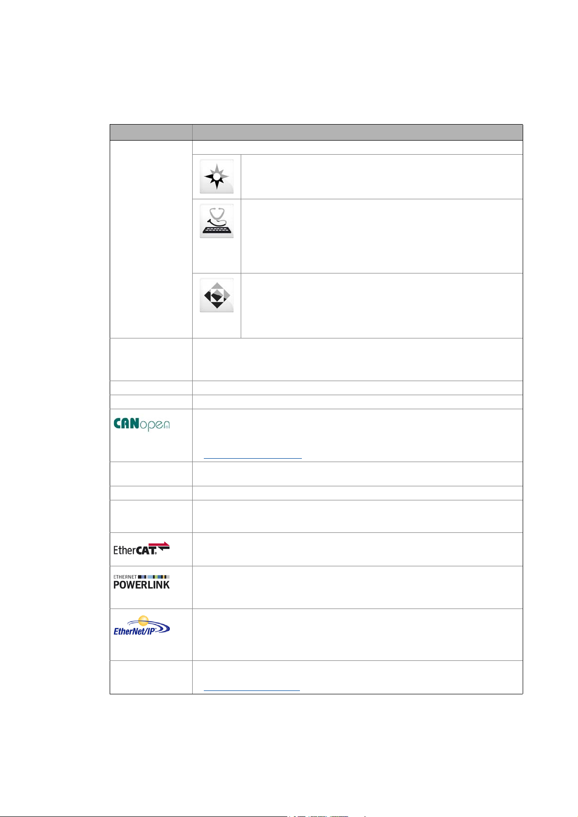
1.3 Terminology used
Term Meaning
Engineering Tools Software solutions for simple engineering at all stages
»EASY Navigator« – Ensures easy operator guidance
• All practical Lenze engineering tools at a glance
• Tools can be selected quickly
• Clearly arranged, simplifying the engineering process from the start
»EASY Starter« – Simple tool for service technicians
• Especially developed for the commissioning and maintenance of Lenze
devices
• Graphical user interface with few buttons
• Simple online diagnostics, parameterisation and commissioning
• No risk of accidentally changing the application
• Ready applications can be loaded to the device
»Engineer« – Multi-device engineering
• For all products from our L-force portfolio
• Practice-oriented user interface
• Easy handling due to graphical user interfaces
• Suitable for all project stages (configuration, commissioning, production)
• Parameter setting and configuration
Application block Block for a technology application (e.g. actuating drive speed)
A technology application is a drive solution based on the experience and know-how of Lenze
in which function blocks interconnected to a signal flow form the basis for implementing
typical drive tasks.
ASM Abbreviation for asynchronous motor
CAN Abbreviation for Controller Area Network. CAN is an asynchronous, serial fieldbus system.
CANopen® is a communication protocol based on CAN. The Lenze system bus (CAN on board)
operates with a subset of this communication protocol.
CANopen® is a registered community trademark of the CAN user organisation CiA® (CAN in
Automation e. V.).
System bus «CAN on board»
Code Parameter used for controller parameterisation or monitoring.
The term is usually called «index».
Display code Parameter that displays the current status or value of an input/output of a system block.
Emergency brake The emergency brake serves to shutdown rotary or translatory masses in motion in
emergency situations. Emergency situations are exceptional situations that only occur
sporadically.
EtherCAT® is a real-time capable Ethernet system with maximum performanc.
EtherCAT® is a registered trademark and patented technology, licensed by the Beckhoff
Automation GmbH, Germany.
Ethernet POWERLINK is a real-time capable fieldbus system based on Ethernet. For user data
exchange, Ethernet POWERLINK specifies a communication protocol based on CANopen.
Ethernet POWERLINK is a patented technology licensed by the Ethernet POWERLINK
Standardization Group (EPSG), Germany.
EtherNet/IP™ (EtherNet Industrial Protocol) is a fieldbus system based on Ethernet which
uses the Common Industrial Protocol™ (CIP™) for data exchange.
EtherNet/IP™ and Common Industrial Protocol™ (CIP™) are trademarks and patented
technologies licensed by the user organisation ODVA (Open DeviceNet Vendor Association),
USA.
FB Editor Abbreviation for function block editor. Graphic interconnection tool which is available in the
»Engineer« for function block interconnections on the FB Editor.
Working with the FB Editor
Lenze · 8400 StateLine · Reference manual · DMS 12.0 EN · 06/2014 · TD05/TD14 17
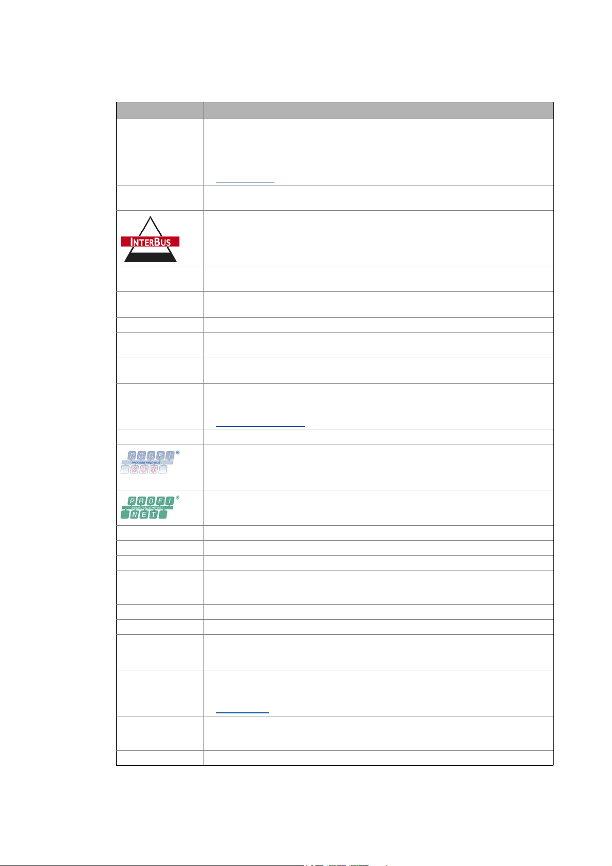
1 About this documentation
1.3 Terminology used
_ _ _ _ _ _ _ _ _ _ _ _ _ _ _ _ _ _ _ _ _ _ _ _ _ _ _ _ _ _ _ _ _ _ _ _ _ _ _ _ _ _ _ _ _ _ _ _ _ _ _ _ _ _ _ _ _ _ _ _ _ _ _ _
Term Meaning
Function block General designation of a function block for free interconnection in the FB Editor.
A function block (short: FB) can be compared with an integrated circuit that contains a
specific control logic and delivers one or several values when being executed. Example:
«L_Arithmetik_1» (FB for arithmetic operations)
Many function block are available several times (e.g. L_And_1, L_And_2 and L_And_3).
Function blocks
Holding brake The holding brake serves to statically hold e.g. a position during the downtimes of a
robot/travelling/synchronous/hoist drive.
INTERBUS was developed as sensor/actuator/bus system for transmitting process data.
Today, maintenance activities for the INTERBUS technologies are carried out by the user
organisation PROFIBUS & PROFINET International (PI).
Keypad The keypad is an alternative to the PC for the local operation, parameterisation, and
LA Abbreviation for Lenze Application block
Lenze setting This setting is the default factory setting of the device.
LP Abbreviation for Lenze Port block
LS Abbreviation for Lenze System block
MCI Abbreviation for Motionbus Communication Interface (fieldbus interface)
Port block Block for implementing the process data transfer via a fieldbus
PSM Abbreviation for permanently excited synchronous motor
QSP Abbreviation for quick stop
SC Abbreviation for Servo Control
Service brake The service brake serves to shutdown rotary or translatory masses in motion in a controlled
SLPSM Abbreviation for sensorless control of synchronous motors
SLVC Abbreviation for SensorLess Vector Control
Subcode If a code contains several parameters, these are stored in «subcodes».
System block System blocks provide interfaces to basic functions, to «free codes» and to the hardware of
USB diagnostic
adapter
VFCplus Abbreviation for Voltage Frequency Control
diagnostics in a simple manner.
Example: «LA_NCtrl» (block for the «Actuating drive speed» application)
Example: «LP_CanIn1» (CAN1 port block)
Example: «LS_DigitalInput» (system block for digital input signals)
The Inverter Drives 8400 can accommodate plug-in communication modules and can
therefore take part in the data transfer of an existing fieldbus system.
Fieldbus interface (MCI)
PROFIBUS® (Process Field Bus) is fieldbus system used worldwide for automating machines
and production plants.
PROFIBUS® is a registered trademark and patented technology licensed by the user
organisation PROFIBUS & PROFINET International (PI).
PROFINET® (Process Field Network) is a real-time capable fieldbus system based on Ethernet.
PROFINET® is a registered trademark and patented technology licensed by the user
organisation PROFIBUS & PROFINET International (PI).
manner. The energy to be dissipated in this process is produced in the form of friction
energy. Unlike emergency braking, this process is a regular and recurring operating mode.
This Manual uses a slash «/» as a separator between code and subcode (e.g. «C00118/3»).
The term is usually called «subindex».
the controller in the FB editor of the »Engineer« (e.g. to the digital inputs). Each system block
is only available once.
System blocks
The USB diagnostic adapter is used for the operation, parameterisation, and diagnostics of
the controller. Data are exchanged between the PC (USB connection) and the controller
(diagnostic interface on the front) via the diagnostic adapter. Order designation: E94AZCUS
18
Lenze · 8400 StateLine · Reference manual · DMS 12.0 EN · 06/2014 · TD05/TD14
1 About this documentation
1.4 Definition of the notes used
_ _ _ _ _ _ _ _ _ _ _ _ _ _ _ _ _ _ _ _ _ _ _ _ _ _ _ _ _ _ _ _ _ _ _ _ _ _ _ _ _ _ _ _ _ _ _ _ _ _ _ _ _ _ _ _ _ _ _ _ _ _ _ _
1.4 Definition of the notes used
The following signal words and symbols are used in this documentation to indicate dangers and
important information:
Safety instructions
Layout of the safety instructions:
Pictograph and signal word!
(characterise the type and severity of danger)
Note
(describes the danger and gives information about how to prevent dangerous
situations)
Pictograph Signal word Meaning
Danger! Danger of personal injury through dangerous electrical voltage
Danger! Danger of personal injury through a general source of danger
Stop! Danger of property damage
Application notes
Pictograph Signal word Meaning
Note! Important note to ensure trouble-free operation
Reference to a n imm inen t dan ger t hat m ay result in death or seri ous p erso nal injury
if the corresponding measures are not taken.
Reference to a n imm inen t dan ger t hat m ay result in death or seri ous p erso nal injury
if the corresponding measures are not taken.
Reference to a possible danger that may result in property damage if the
corresponding measures are not taken.
Tip! Useful tip for easy handling
Lenze · 8400 StateLine · Reference manual · DMS 12.0 EN · 06/2014 · TD05/TD14 19

2 Introduction: Parameterising the controller
_ _ _ _ _ _ _ _ _ _ _ _ _ _ _ _ _ _ _ _ _ _ _ _ _ _ _ _ _ _ _ _ _ _ _ _ _ _ _ _ _ _ _ _ _ _ _ _ _ _ _ _ _ _ _ _ _ _ _ _ _ _ _ _
2 Introduction: Parameterising the controller
Being a component of a machine which includes a speed-variable drive system, the controller needs
to be adjusted to its drive task. The controller is adjusted by changing parameters which are saved
in the memory module. The parameters can be accessed by keypad, by the »EASY Starter« or by the
»Engineer«. Access is also possible by a master control via fieldbus communication. For this purpose,
the «CAN on board» CAN interface and the MCI interface for using a communication module (e.g.
PROFIBUS) are available.
Danger!
In general, changing a parameter causes an immediate response in the controller!
An enabled controller can cause an unwanted behaviour at the motor shaft! For
instance, setpoint sources can change over abruptly (e.g. when the signal source is
configured for the main setpoint).
Certain device commands or settings which may cause critical states of drive behaviour
constitute exceptions. Such parameter changes are only possible if the controller is
inhibited. Otherwise, a corresponding error message will be issued.
20 Lenze · 8400 StateLine · Reference manual · DMS 12.0 EN · 06/2014 · TD05/TD14
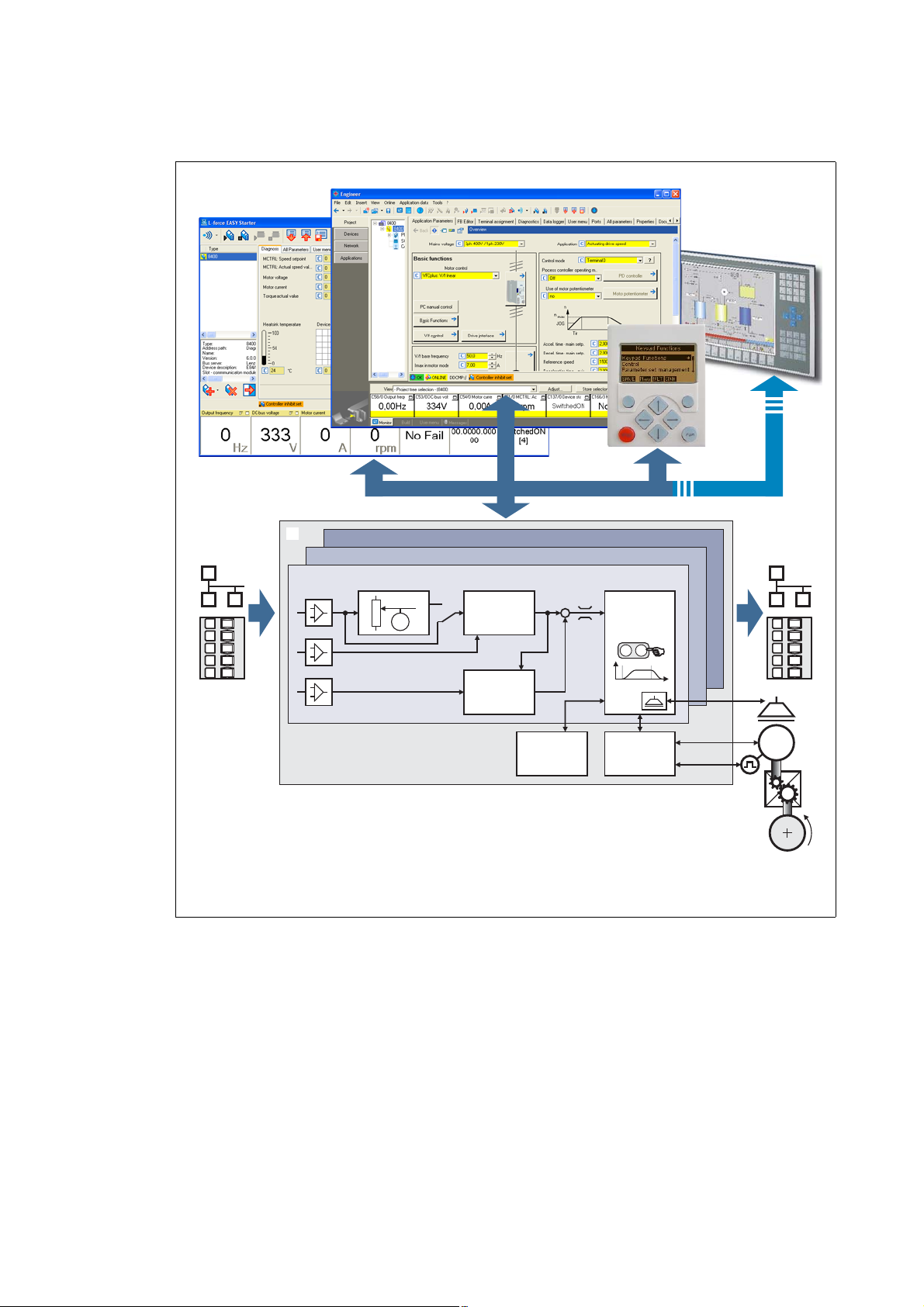
2 Introduction: Parameterising the controller
M
…
M
n
t
è
ç
02
1
Switch-off positioning
Actuating drive speed
Setpoint
generator
Process
controller
Motion
Control
Kernel
Device
control
Motor
control
Signal
inputs
Signal
outputs
Parameterisation
Fieldbus
L-force EASY Starter
L-force Engineer
Keypad
_ _ _ _ _ _ _ _ _ _ _ _ _ _ _ _ _ _ _ _ _ _ _ _ _ _ _ _ _ _ _ _ _ _ _ _ _ _ _ _ _ _ _ _ _ _ _ _ _ _ _ _ _ _ _ _ _ _ _ _ _ _ _ _
Signal inputs for control and setpoint signals
Signal flow of the integrated technology application (see the following subchapter)
Signal outputs for status and actual value signals
[2-1] Adaptation of the drive solution via parameter setting
Lenze · 8400 StateLine · Reference manual · DMS 12.0 EN · 06/2014 · TD05/TD14 21
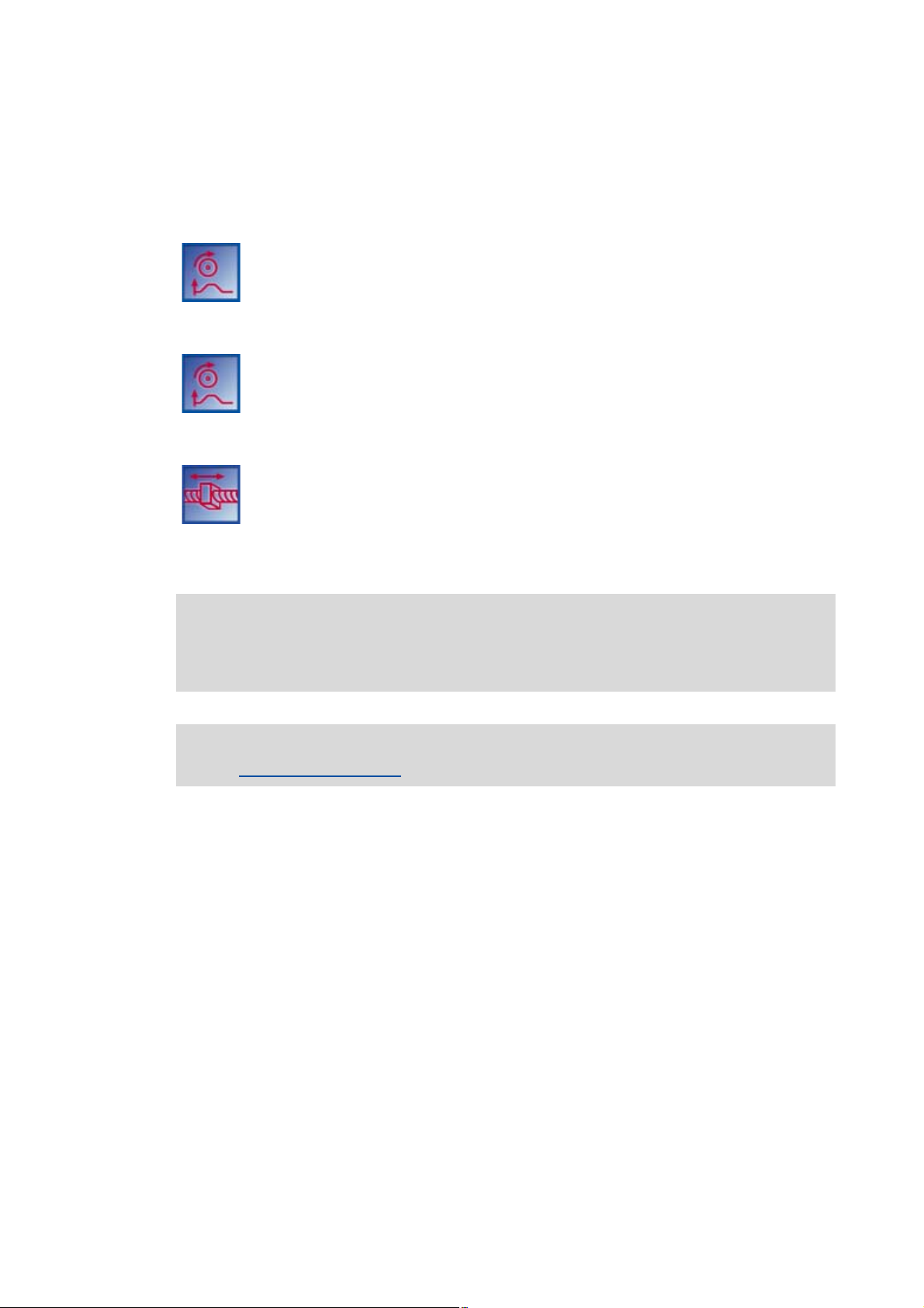
2 Introduction: Parameterising the controller
2.1 Integrated technology applications
_ _ _ _ _ _ _ _ _ _ _ _ _ _ _ _ _ _ _ _ _ _ _ _ _ _ _ _ _ _ _ _ _ _ _ _ _ _ _ _ _ _ _ _ _ _ _ _ _ _ _ _ _ _ _ _ _ _ _ _ _ _ _ _
2.1 Integrated technology applications
The following technology applications integrated in the drive controller 8400 StateLine provide the
main signal flow for the implementation of a general or a special drive solution:
Technology application «Actuating drive speed»
This preset technology application serves to solve speed-controlled drive tasks, e.g.
conveyor drives (interconnected), extruders, test benches, vibrators, travelling drives,
presses, machining systems, metering units.
technology application «Actuating drive speed (AC Drive Profile)»
This technology application available from version 13.00.00 provides a speed and
torque control by means of «AC Drive Profile». The fieldbuses EtherNet/IP™ and
system bus (CANopen) are supported.
«Switch-off positioning» technology application
This technology application available from version 04.00.00 is used to solve speedcontrolled drive tasks which require a pre-switch off or stopping at certain positions,
e.g. roller conveyors and conveying belts. The pre-switch off is implemented by
connecting switch-off sensors.
Note!
Please note that the «StateLine», «HighLine» and «TopLine» device types differ with regard
to the number, functional range, and flexibility of the technology applications offered.
Detailed information on each technology application can be found in the main chapter
«Technology applications
«. ( 296)
22
Lenze · 8400 StateLine · Reference manual · DMS 12.0 EN · 06/2014 · TD05/TD14

2 Introduction: Parameterising the controller
2.1 Integrated technology applications
_ _ _ _ _ _ _ _ _ _ _ _ _ _ _ _ _ _ _ _ _ _ _ _ _ _ _ _ _ _ _ _ _ _ _ _ _ _ _ _ _ _ _ _ _ _ _ _ _ _ _ _ _ _ _ _ _ _ _ _ _ _ _ _
2.1.1 Purpose of the technology applications
The stepped Inverter Drives 8400 series provides solutions for simple to complex applications –
depending on the user’s experience and knowledge about the handling of drives and drive tasks.
On the one hand, a great scope of standard drive tasks for frequency inverters is covered by the
technology applications offered by Lenze, and on the other hand, the user is relieved from timeconsuming programming activities. In practice, some drive tasks are alike so that minor
modifications of the corresponding technology applications lead to quick results.
Other important features of technology applications are:
• Direct implementation of drive tasks without recreating a function block interconnection inside
the device
• Operation via keypad and/or operation via convenient operator dialogs in the «Engineer».
• Commissioning via few operating and diagnosing parameters (local keypad operation).
• Achieving a transparency as high as possible via the integrated functionality of the device by
representing signal flow diagrams.
• Provision of a basic functionality suitable and often sufficient for many applications.
2.1.2 Application cases for a technology application
You should use a technology application if
• the task can be solved completely or to a great extent by the basic functionality of the
technology application.
• the end customer does not want to create the comprehensive core functions of the
corresponding technology on his own.
• the creation time for a project is to be reduced by using the ready-made technology application
• the end customer wants to build upon the know-how of Lenze.
Tip!
If the end customer of the machine does not want to use ready-made Lenze functions, it is
also possible to implement individual drive solutions with the «StateLine C», «HighLine C»
and «TopLine C» versions in the form of «free interconnections». (In case of «StateLine C2,
free interconnection is only possible from version 12.00.00 and »Engineer« V2.17.)
Here, a technology application can be used as starting basis, which has to be adapted to the
requirement by a change or extension via function block editor (see the following chapter).
Lenze · 8400 StateLine · Reference manual · DMS 12.0 EN · 06/2014 · TD05/TD14 23

2 Introduction: Parameterising the controller
2.1 Integrated technology applications
_ _ _ _ _ _ _ _ _ _ _ _ _ _ _ _ _ _ _ _ _ _ _ _ _ _ _ _ _ _ _ _ _ _ _ _ _ _ _ _ _ _ _ _ _ _ _ _ _ _ _ _ _ _ _ _ _ _ _ _ _ _ _ _
2.1.3 Technology application = function block interconnection
In case of the 8400 device version, each technology application is connected to a «function block
interconnection» («FB interconnection»). This FB interconnections serve to implement signal
interconnections. Various FBs are available for digital signal processing, signal conversion and logic
modules.
For special drive tasks it has proved of value to use the integrated technology applications as a basis
for modifications or extensions of the available FB interconnections.
I/O level & application level
The interconnection of the interfaces is shown in the I/O level of the function block editor according
to the selected control mode. In the «deeper» application level, the main signal flow is realised in the
form of an interconnection of various function and system blocks.
For the device versions «StateLine C», «HighLine C» and «TopLine C» the following applies:
• The preconfigured signal links can be reconfigured in the I/O level if required.
• Moreover, applications integrated in the controller can be reconfigured in the application level
and extended by individual functions.
• Moreover, experienced users are offered the opportunity to implement their own drive
solutions independent of the predefined technology applications by using so-called «free
interconnections». (In case of «StateLine C», free interconnection is only possible from version
12.00.00 and »Engineer« V2.17.)
Motion Control Kernel
Important basic (drive) functions as well as further basic functionalities are implemented in the
firmware of the drive controller in the so-called Motion Control Kernel (MCK) which can be accessed
by the active technology application via defined internal interfaces. By this means the expensive
creation of single function block interconnections is omitted so that the expenditure and the
complexity for the realisation of standard functions is minimised.
The Motion Control Kernel is integrated in the main setpoint path and, depending on the set
operating mode, it creates the required control and setpoint signals for the motor control and the
drive interface.
More detailed information:
• A detailed description of the basic functions implemented in the Motion Control
Kernel can be found in the main chapter «Basic drive functions (MCK)
• Detailed information on the creation or change of interconnections by means of the
function block editor can be found in the main chapter «Working with the FB Editor
( 857)
• All available function and system blocks are described in the main chapter «Function
library«. ( 909)
«. ( 390)
«.
24
Lenze · 8400 StateLine · Reference manual · DMS 12.0 EN · 06/2014 · TD05/TD14
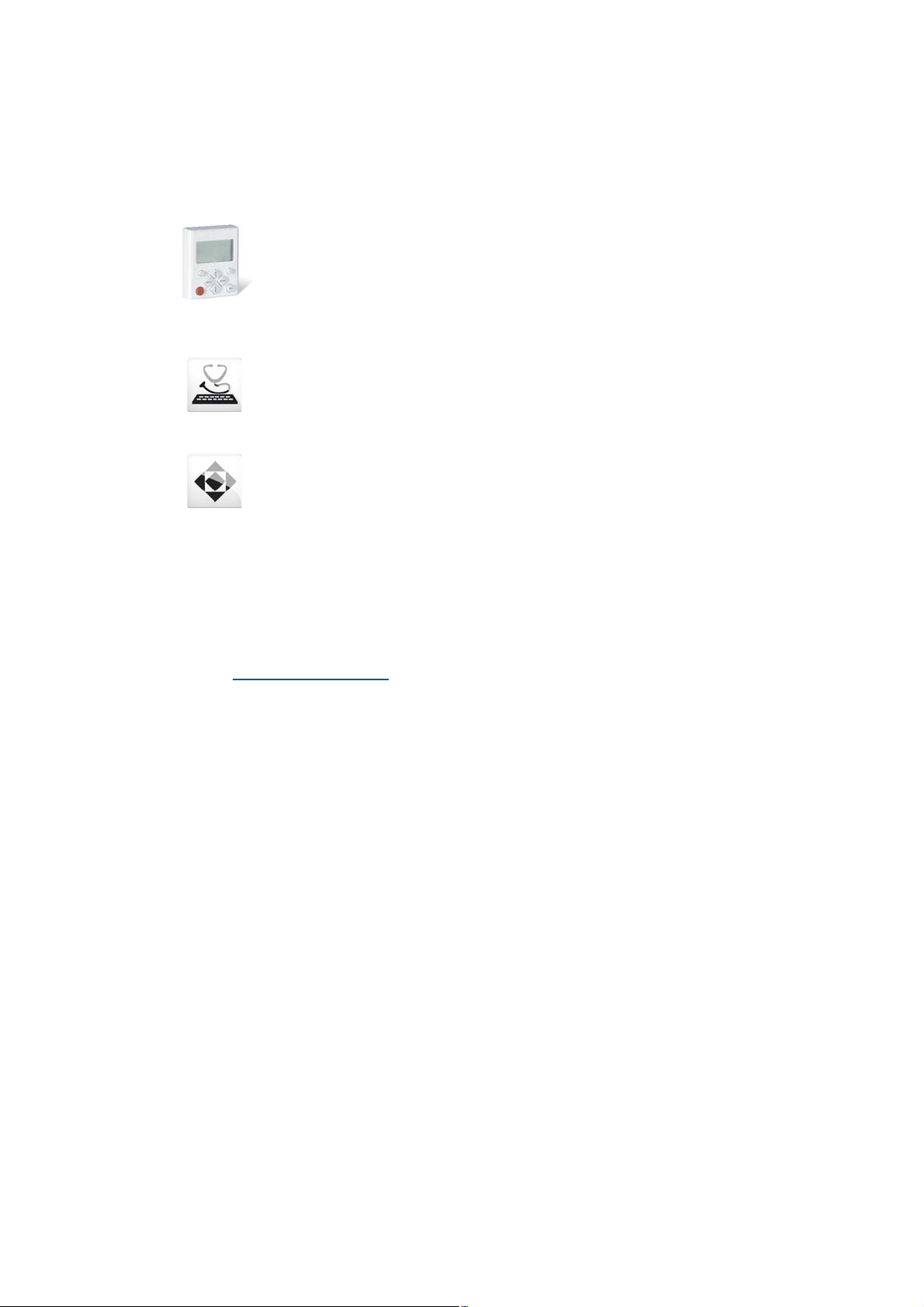
2 Introduction: Parameterising the controller
2.2 Selection of the appropriate commissioning tool
_ _ _ _ _ _ _ _ _ _ _ _ _ _ _ _ _ _ _ _ _ _ _ _ _ _ _ _ _ _ _ _ _ _ _ _ _ _ _ _ _ _ _ _ _ _ _ _ _ _ _ _ _ _ _ _ _ _ _ _ _ _ _ _
2.2 Selection of the appropriate commissioning tool
There are several possibilities for commissioning the 8400 StateLine controller:
Commissioning via keypad X400 (or diagnosis terminal X400)
The keypad is an alternative to the PC for the local operation, parameterisation, and
diagnostics in a simple manner. The keypad is especially suited for test and
demonstration purposes and for the case that only few parameters have to be
adapted.
Commissioning using PC and »EASY Starter«
The »EASY Starter« is a Lenze tool for simple online diagnostics, parameterisation and
commissioning of the controller.
Commissioning using PC and »Engineer«
The »Engineer« is a Lenze engineering software for parameter setting across all
devices, configuring and diagnosing individual components (as for instance
controllers, industrial PCs, motors, I/O systems) and machine control systems.
Tip!
The engineering tools »EASY Starter« and »Engineer StateLevel« are provided free of charge
in the internet:
http://www.lenze.com
For communication between PC and controller, the USB diagnostic adapter can be used for
instance (see the following subchapter).
Download Software Downloads
Lenze · 8400 StateLine · Reference manual · DMS 12.0 EN · 06/2014 · TD05/TD14 25
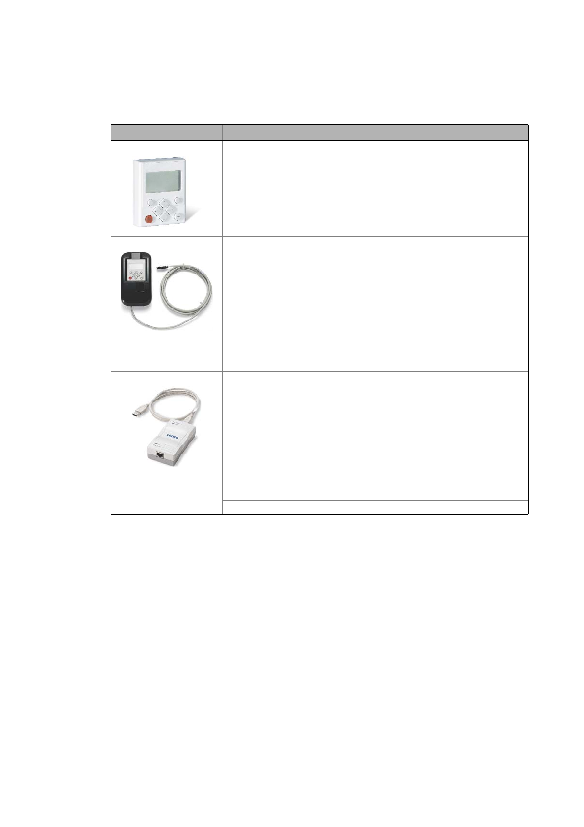
2 Introduction: Parameterising the controller
2.2 Selection of the appropriate commissioning tool
_ _ _ _ _ _ _ _ _ _ _ _ _ _ _ _ _ _ _ _ _ _ _ _ _ _ _ _ _ _ _ _ _ _ _ _ _ _ _ _ _ _ _ _ _ _ _ _ _ _ _ _ _ _ _ _ _ _ _ _ _ _ _ _
2.2.1 Overview: Accessories for commissioning
Version Features Product key
Keypad X400 Quick access to parameters and operating data
• Supports hot plugging
• Graphic display with plain texts
• Backlighting
• Easy user guidance
• 4 navigation keys, 2 context-sensitive keys
•Adjustable RUN/STOP function
• Can be used for L-force Inverter Drives 8400 and Servo
Drives 9400
Diagnosis terminal X400 Keypad X400 in a robust housing, also suitable for
USB diagnostic adapter For electrical isolation of your PC and the controller.
installation into the control cabinet door.
• Supports hot plugging
• Graphic display with plain texts
• Backlighting
• Easy user guidance
• 4 navigation keys, 2 context-sensitive keys
•Adjustable RUN/STOP function
• Incl. 2.5 m cable
• Enclosure IP20; in case of front installation in control
cabinet IP65
• Can be used for L-force Inverter Drives 8400 and Servo
Drives 9400
• Supports hot plugging
• Diagnostic LED for data transfer display
• plug and play
• Input-side voltage supply via USB connection from PC
• Output-side voltage supply via the diagnostic interface of
the controller
• Connecting cables can be selected in various lengths:
EZAEBK1001
EZAEBK2001
E94AZCUS
Connecting cable for
USB diagnostic adapter
2.5 m length EWL0070
5 m length EWL0071
10 m length EWL0072
26
Lenze · 8400 StateLine · Reference manual · DMS 12.0 EN · 06/2014 · TD05/TD14

2 Introduction: Parameterising the controller
2.3 General notes on parameters
_ _ _ _ _ _ _ _ _ _ _ _ _ _ _ _ _ _ _ _ _ _ _ _ _ _ _ _ _ _ _ _ _ _ _ _ _ _ _ _ _ _ _ _ _ _ _ _ _ _ _ _ _ _ _ _ _ _ _ _ _ _ _ _
2.3 General notes on parameters
All parameters for controller parameterising or monitoring are saved as so-called «codes».
• The codes are numbered and indicated by the prefix «C» before the code, e.g. «C00002».
• Moreover, each code has a name and specific attributes, as for example access type (reading,
writing), data type, limit values and default setting («Lenze setting»).
• For the sake of clarity, some codes contain «subcodes» for saving parameters. This Manual uses
a slash «/» as a separator between code and subcode, e.g. C00118/3″.
• According to their functionality, the parameters are divided into three groups:
• Setting parameters: For specifying setpoints and for setting device / monitoring functions.
• Configuration parameters: For configuring signal connections and terminal assignments.
• Diagnostic/display parameters: For displaying device-internal process factors, current actual
values and status messages. These are read-only parameters.
Lenze · 8400 StateLine · Reference manual · DMS 12.0 EN · 06/2014 · TD05/TD14 27
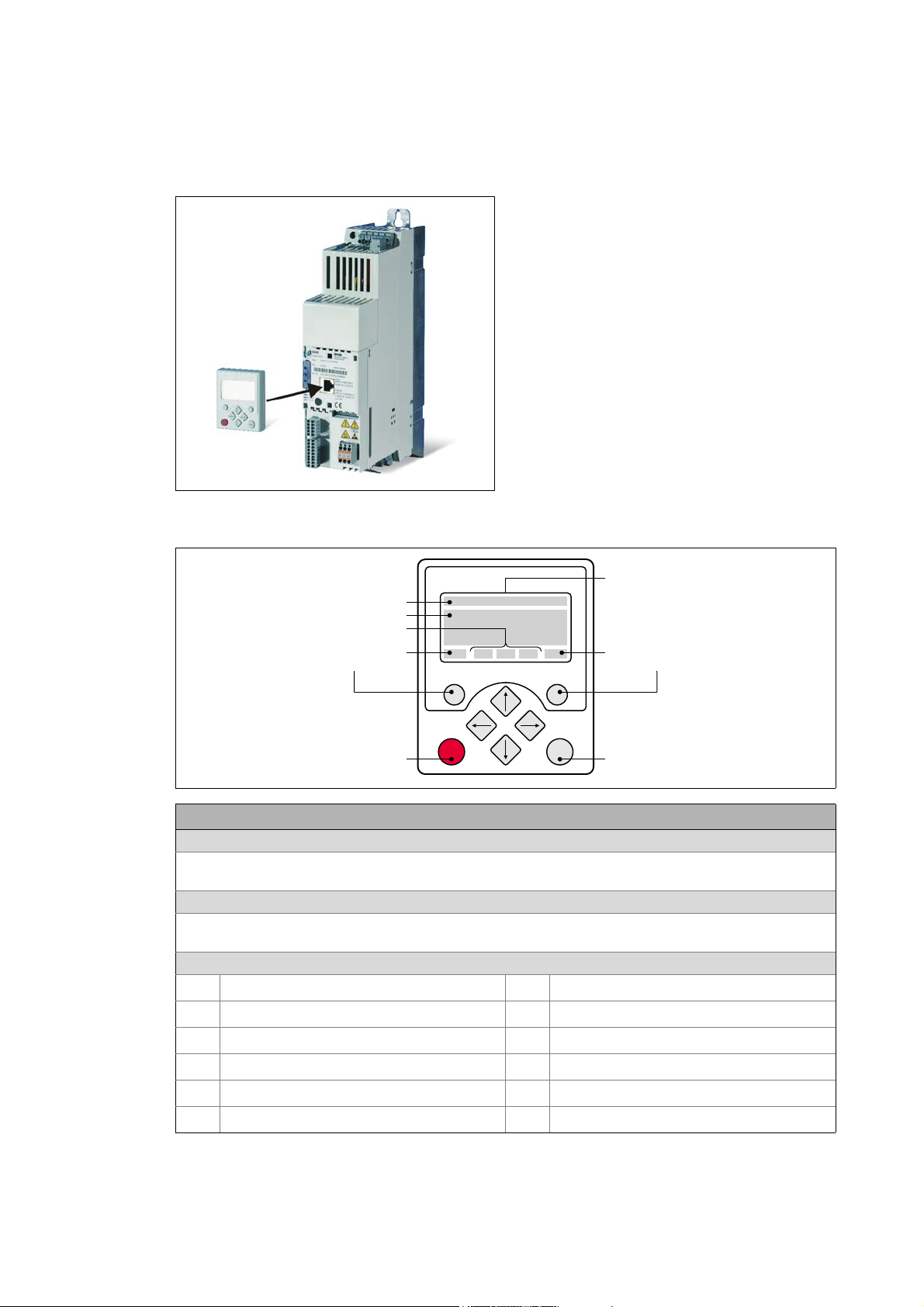
2 Introduction: Parameterising the controller
WXST VYR
+HDGOLQH
7ULSOHOLQHGLVSOD\
&XUUHQWIXQFWLRQ
ULJKWIXQFWLRQNH\
&XUUHQWIXQFWLRQ
OHIWIXQFWLRQNH\
/&’GLVSOD\
‘HYLFHVWDWH
,QPDQXDOFRQWUROPRGH
6WDUWPRWRU
,QPDQXDOFRQWUROPRGH
6WRSPRWRU
2.3 General notes on parameters
_ _ _ _ _ _ _ _ _ _ _ _ _ _ _ _ _ _ _ _ _ _ _ _ _ _ _ _ _ _ _ _ _ _ _ _ _ _ _ _ _ _ _ _ _ _ _ _ _ _ _ _ _ _ _ _ _ _ _ _ _ _ _ _
2.3.1 Changing the parameterisation with the keypad
The keypad is simply plugged on the diagnostic
interface X6 («DIAG») at the front of the standard
device.
Plugging and unplugging the keypad is possible
during operation.
Keypad display and control elements
LCD display
Headline
In the menu level: Menu name
In the parameter level: Parameter name
Three-part display
In the menu level: List of available menus
In the parameter level: Code/subcode and setting or actual value
Device status
Controller is switched on
Controller is enabled
Controller is inhibited
Quick stop active
Current limit exceeded
Speed controller 1 in the limitation
Pulse inhibit active
System fault active
«Fault» device status is active
«Trouble» device status is active
«TroubleQSP» device status is active
A warning is indicated
28
Lenze · 8400 StateLine · Reference manual · DMS 12.0 EN · 06/2014 · TD05/TD14
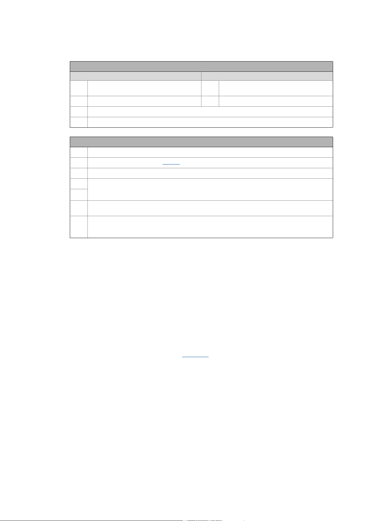
2 Introduction: Parameterising the controller
2.3 General notes on parameters
_ _ _ _ _ _ _ _ _ _ _ _ _ _ _ _ _ _ _ _ _ _ _ _ _ _ _ _ _ _ _ _ _ _ _ _ _ _ _ _ _ _ _ _ _ _ _ _ _ _ _ _ _ _ _ _ _ _ _ _ _ _ _ _
LCD display
Function — left function key Function — right function key
Change parameter setting
(change to editing mode)
Back to main menu
Parameter can only be changed when the controller is inhibited
Save all parameter settings in the memory module safe against mains failure
Control elements
Execute the function assigned to the function key (see LCD display)
Execute the stop function set in C00469 (Lenze setting: Inhibit controller)
Deactivate stop function again (Lenze setting: Enable controller again)
In the menu level: Select menu/submenu
In the parameter level: Select parameter
In the editing mode: Change marked digits or select list entry
In the menu level: Select submenu/change to parameter level
In the editing mode: Cursor to the right
In the menu level: One menu level higher (if available)
In the parameter level: Back to the menu level
In the editing mode: Cursor to the left
Accept change in the controller
(no saving with mains failure protection
Abort (discard change)
)
Menu structure
In the keypad, the parameters are classified into various menus and submenus.
•The USER menu includes a selection of frequently used parameters.
•The Code list contains all parameters.
•The Go to param function enables you to reach the corresponding parameter directly.
•The Logbook logs all errors and their chronological history.
•The Diagnostics menu contains diagnostic/display parameters for displaying device-internal
process factors, current actual values and status messages.
Userlevel
From version 12.00.00 onwards, the extent of menus, submenus an codes shown in the keypad can
be adapted by selecting the «Userlevel» in C00001/1
:
• Userlevel Standard (Lenze setting): Only the most important menus and codes are shown in the
keypad.
• Userlevel Expert: All menus and codes are shown in the keypad.
• Userlevel Service: For service purposes only (Lenze service).
The the Userlevel has been changed, the menus are restructured in the keypad according to the
selected Userlevel. The parameters of a plugged in communication module are always displayed
completely independent of the set Userlevel.
Lenze · 8400 StateLine · Reference manual · DMS 12.0 EN · 06/2014 · TD05/TD14 29
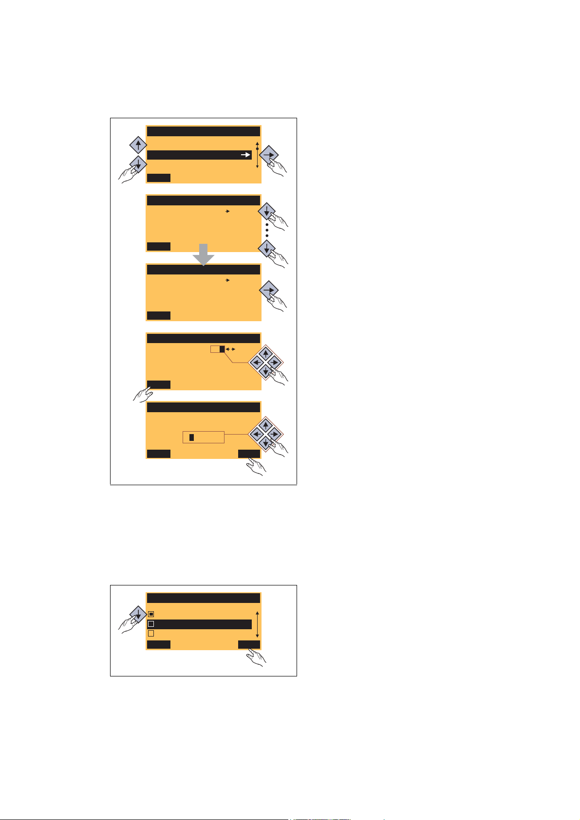
2 Introduction: Parameterising the controller
Load Lenze setting
C00002/001
Off / Finished
EDIT
Par1 8400 StateLine C
SAVE
Code list
Go To Param
USER — Menu
Fixed setpoint 1
C00039/001
40.00 %
EDIT
Fixed setpoint 2
60.00 %
EDIT
C00039/002
Fixed setpoint 2
C00039/002
ESC
60.00 %
OK
1.
2.
3.
5.
4.
6.
Language
ESC
Français
Deutsch
English
OK
2.3 General notes on parameters
_ _ _ _ _ _ _ _ _ _ _ _ _ _ _ _ _ _ _ _ _ _ _ _ _ _ _ _ _ _ _ _ _ _ _ _ _ _ _ _ _ _ _ _ _ _ _ _ _ _ _ _ _ _ _ _ _ _ _ _ _ _ _ _
General operation
1. Use the / navigation keys to select the
desired menu.
•Use the / navigation keys to reach a
higher/lower menu level.
•Use the function key to return to the
main menu.
2. Use the / navigation keys to select the
parameter to be set within a submenu.
3. In order to select another subcode in case of a
parameter with subcodes:
• Press the navigation key to change tot he
editing mode for the subcode.
• Use the navigation keys to set the desired
subcode.
4. Use the function key to switch over to the
editing mode.
[2-2] Example: Changing parameters with the keypad
5. Use the navigation keys to set the desired value.
6. Use the function key to accept the change
and to leave the editing mode.
•Use the function key to leave the editing
mode without accepting the change.
Multilingualism
All texts displayed in the keypad are in English.
From version 11.00.00 onwards, the most important menus as well as diagnostic and configuration
parameters can are also available in German and French. To set a different language, select the
Language selection menu item in the main menu of the keypad.
• The multilingual texts are stored in the
controller and do not have to be loaded into the
device.
• For reasons of disc space, only the most
important menus and parameters as well as the
error messages are available in several
languages.
30
Lenze · 8400 StateLine · Reference manual · DMS 12.0 EN · 06/2014 · TD05/TD14
Loading…